Manual NXSB 100 Board Documentation Rev03...
40
7 Device Description NXSB 100 netX StarterKitBoard Edition: 3 Language: English (EN) Hilscher Gesellschaft für Systemautomation mbH Rheinstraße 15 D-65795 Hattersheim Germany Tel. +49 (0) 6190 / 9907 - 0 Fax. +49 (0) 6190 / 9907 - 50 Sales: +49 (0) 6190 / 9907 - 0 netX Support: +49 (0) 6190 / 9907 - 97 Sales email: [email protected] netX Support email: [email protected]
-
Upload
nguyentram -
Category
Documents
-
view
218 -
download
3
Transcript of Manual NXSB 100 Board Documentation Rev03...

7
Device Description
NXSB 100 netX StarterKitBoard
Edition: 3 Language: English (EN)
Hilscher Gesellschaft für Systemautomation mbH
Rheinstraße 15 D-65795 Hattersheim
Germany
Tel. +49 (0) 6190 / 9907 - 0 Fax. +49 (0) 6190 / 9907 - 50
Sales: +49 (0) 6190 / 9907 - 0
netX Support: +49 (0) 6190 / 9907 - 97
Sales email: [email protected] netX Support email: [email protected]
NXSB100 - NetX StarterKitBoard Description • 2
Copyright • Hilscher Gesellschaft für Systemautomation mbH • Oi:NXSB100#3EN
List of Revisions Index Date Version Chapter Revisions
1 22.11.05 All Created
2 08.05.06 All Add block diagram, more detailed description
3 19.10.06 All Revised, JL, AJ
Although this device has been developed with great care and intensively tested, Hilscher Gesellschaft für Systemautomation mbH can not guarantee the suitability of this device for any purpose not confirmed by us in writing.
Guarantee claims shall be limited to the right to require rectification. Liability for any damages which may have arisen from the use of this device or its documentation shall be limited to cases of intent.
We reserve the right to modify our products and their specifications at any time in as far as this contribute to technical progress. The version of the manual supplied with the device applies.

NXSB100 - NetX StarterKitBoard Description • 3
Copyright • Hilscher Gesellschaft für Systemautomation mbH • Oi:NXSB100#3EN
Table of Contents
1 DESCRIPTION............................................................................................................5 1.1 Introduction .................................................................................................................5
1.1.1 netX Technology...................................................................................................5 1.1.2 NXSB 100 Starter Board ......................................................................................6
1.2 Overview NXSB 100 ...................................................................................................7 1.3 Block Diagram ............................................................................................................8
2 DISPLAY AND CONTROL ELEMENTS......................................................................9 2.1 LEDs ...........................................................................................................................9
2.1.1 Power LED ...........................................................................................................9 2.1.2 SYS LED ..............................................................................................................9 2.1.3 Digital Output LEDs..............................................................................................9 2.1.4 Fieldbus Status LEDs...........................................................................................9
2.2 Buttons......................................................................................................................10 2.2.1 Reset Button.......................................................................................................10 2.2.2 Boot Button.........................................................................................................10 2.2.3 Input Buttons ......................................................................................................10
2.3 Jumpers ....................................................................................................................10
3 CONNECTORS.........................................................................................................11 3.1 Power Supply............................................................................................................11 3.2 Communication Interfaces ........................................................................................12
3.2.1 PROFIBUS Interface ..........................................................................................12 3.2.2 DeviceNet Interface............................................................................................13 3.2.3 Ethernet Interface...............................................................................................14 3.2.4 RS232 Interface..................................................................................................15 3.2.5 USB Interface .....................................................................................................16 3.2.6 XMAC I/O signals ...............................................................................................16
3.3 Dual-Port-Memory, Extension-Bus, PIOs .................................................................17 3.4 AD Converter ............................................................................................................19 3.5 JTAG Interface..........................................................................................................20
4 SOFTWARE TOOLS.................................................................................................21 4.1 Debug System Software - HiTOP .............................................................................21
4.1.1 Minimum Project Requirements .........................................................................21 4.1.2 Loading an Example Project with the HiTOP Environment................................21 4.1.3 Defining a new Project with the HiTOP Environment.........................................24 4.1.4 Tool Settings.......................................................................................................27 4.1.5 Build Configuration .............................................................................................28 4.1.6 Linker Script File.................................................................................................31 4.1.7 Build / Rebuild ....................................................................................................31
4.2 netX Bootwizard........................................................................................................32
NXSB100 - NetX StarterKitBoard Description • 4
Copyright • Hilscher Gesellschaft für Systemautomation mbH • Oi:NXSB100#3EN
4.2.1 Startup ................................................................................................................32 4.2.2 Function “build bootimage”.................................................................................34 4.2.3 Function “flash bootimage to SPI flash” .............................................................36
5 LISTS ........................................................................................................................39 5.1 List of Figures ...........................................................................................................39 5.2 List of Tables ............................................................................................................40

NXSB100 - NetX StarterKitBoard Description • 5
Copyright • Hilscher Gesellschaft für Systemautomation mbH • Oi:NXSB100#3EN
1 Description 1.1 Introduction
1.1.1 netX Technology The netX is a highly integrated network controller with a new system architecture optimized for communication and maximum data throughput. Based on the 32-Bit CPU ARM 926EJ-S clocked with 200 MHz, it provides a memory management unit, caches, DSP and Java extensions. Together with 32 Kbytes ROM holding the Bootloader and a Real-Time kernel, the internal memory of 144 Kbytes RAM is sufficient for smaller applications. The connection to a primary host is accomplished by the dual-port memory mode of the host interface, which is also configurable as a 16 Bit extension bus for stand-alone applications. Comprehensive peripheral functions, serial interfaces such as UARTs, USB, SPI and I²C provide a wide spectrum of applications. Yet, it is the central data switch and the four freely configurable communication channels with their own intelligence that are the main characteristics of the netX as a "high end” network controller.
Figure 1: netX Block Diagramm

NXSB100 - NetX StarterKitBoard Description • 6
Copyright • Hilscher Gesellschaft für Systemautomation mbH • Oi:NXSB100#3EN
The data switch interconnects the ARM CPU, communication and Host controllers, memory blocks and peripheral units via five data paths. This allows the controllers to transmit their data in parallel, contrary to the traditional sequential architecture with only one common data bus and additional bus arbitration cycles.
The controllers of the four communication channels are structured on two levels and are identical to each other. They consist of dedicated ALUs and special logic units that receive their protocol functions via Microcode, combining the performance of dedicated (single-) protocol controllers with the flexibility of a CPU. Two of these channels can further be linked to integrated PHYs for Ethernet communication. The Medium-Access-Controller xMAC sends or receives the serial data stream according to the respective bus access process and encrypts or converts these into Bytes. The Protocol Execution Controller xPEC compiles these into data packets and controls the telegram traffic, accomplished by DMA transfers. In addition, every channel has a Dual-port-memory available for status information or as local data image. By its intelligent communication ALUs, the netX can implement the most varied protocols and protocol combinations and can synchronize them independently of the CPU response time – an absolutely new feature in industrial communication technology.
1.1.2 NXSB 100 Starter Board The NXSB 100 is a low cost and yet extensive Evaluation- and Development platform for the netX Chip. It is equipped with 4MB of serial Flash and 8MB SDRAM. Further, the board provides two 100Mbit Ethernet Ports for Real-time Ethernet communication, PROFIBUS-Slave and DeviceNet interfaces. As standard communication ports the user will find one RS-232 serial port, as well as an USB (1.1. full speed) port which operates as Device.. The host interface can be configured as dual-port memory, extension bus or general I/Os and is available through a 64 pin header. All elements of the board are powered by an onboard switching power supply, which can be powered by a wide range of simple (unregulated) standard power supplies from 9V to 24V output voltage. For software development, all NXSB100 boards come with a standard JTAG connector, allowing to connect an appropriate debugger device. NOTE: Like all Hilscher starterboards, also the NXSB 100 uses simplified circuits (no galvanic isolation) for its physical fieldbus interfaces and is also in no way optimized in terms of EMC compatibility. This product is intended to be used for evaluation and development purposes in lab environments only and is not suitable for production use!

NXSB100 - NetX StarterKitBoard Description • 7
Copyright • Hilscher Gesellschaft für Systemautomation mbH • Oi:NXSB100#3EN
PROFIBUS Interface (DSub male connector 9 pin)
Power Supply
LED Power Supply
Dual-Port Memory Extension Bus
USB Interface
Communication Interface RS232 (DSub male connector)
JTAG Interface Debugger
Status LED (yellow/green), SYSModule Network Status LED (red/green), MNS
Status LED (red/yellow), COM
Input (Button)
Digital Input /Output LEDs (yellow), user defined
Reset Button
Boot Button
Ethernet Interface - channel 0 (CH 0, RJ45 female connector)
Ethernet Interface - channel 1 (CH 1, RJ45 female connector)
XM2 / XM3 IOs
DeviceNet Interface(Combicon male connector 5 pin)
1.2 Overview NXSB 100
Figure 2: Overview NXSB 100

NXSB100 - NetX StarterKitBoard Description • 8
Copyright • Hilscher Gesellschaft für Systemautomation mbH • Oi:NXSB100#3EN
netX 500
PHY0_TXP
PHY0_TXNPHY0_RXP
PHY0_RXN
PHY1_TXP
PHY1_TXNPHY1_RXP
PHY1_RXN
XTI
XTO
Power onReset
DPMExtension BusPIO32-83
25 MHz
4 MBFLASH
EthernetChannel 0
SPI
Memory
LinkTX/RX
XM1_IO0XM1_IO1
XM0_IO0XM0_IO1
XM3_IO0
XM2_IO1
XM2_IO0
PIO 4
USB
UART0GPIO0-3
3.3V1.5V
PROFIBUS
R/Cimpedancematching
ADC
EthernetChannel 1
LinkTX/RX
RSTIN
POR
VDDIO
VDDC
JTAG
RUN
RDY
R/Cimpedancematching
RS232C
9-24V3.3V
DPMExtension Bus
PIO32-83
I1-4
O1-4
RESET
USB
XM3_IO1
DeviceNet
Boot
SYS
MNS
COM
JTAG
9-24V
ADCX5
NXSB 100
8 MBSDRAM PIO 5
PIO 6PIO 7
24V
5V
XM2_TXXM2_RX
XM3_TX
XM3_RX
1.3 Block Diagram
Figure 3: Block Diagram NXSB 100
NXSB100 - NetX StarterKitBoard Display and Control Elements • 9
Copyright • Hilscher Gesellschaft für Systemautomation mbH • Oi:NXSB100#3EN
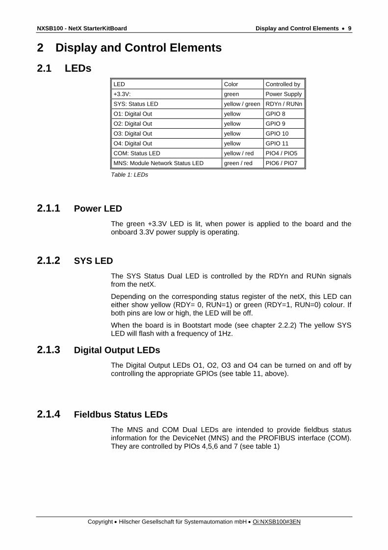
2 Display and Control Elements 2.1 LEDs
LED Color Controlled by
+3.3V: green Power Supply
SYS: Status LED yellow / green RDYn / RUNn
O1: Digital Out yellow GPIO 8
O2: Digital Out yellow GPIO 9
O3: Digital Out yellow GPIO 10
O4: Digital Out yellow GPIO 11
COM: Status LED yellow / red PIO4 / PIO5
MNS: Module Network Status LED green / red PIO6 / PIO7
Table 1: LEDs
2.1.1 Power LED The green +3.3V LED is lit, when power is applied to the board and the onboard 3.3V power supply is operating.
2.1.2 SYS LED The SYS Status Dual LED is controlled by the RDYn and RUNn signals from the netX.
Depending on the corresponding status register of the netX, this LED can either show yellow (RDY= 0, RUN=1) or green (RDY=1, RUN=0) colour. If both pins are low or high, the LED will be off.
When the board is in Bootstart mode (see chapter 2.2.2) The yellow SYS LED will flash with a frequency of 1Hz.
2.1.3 Digital Output LEDs The Digital Output LEDs O1, O2, O3 and O4 can be turned on and off by controlling the appropriate GPIOs (see table 11, above).
2.1.4 Fieldbus Status LEDs The MNS and COM Dual LEDs are intended to provide fieldbus status information for the DeviceNet (MNS) and the PROFIBUS interface (COM). They are controlled by PIOs 4,5,6 and 7 (see table 1)

NXSB100 - NetX StarterKitBoard Display and Control Elements • 10
Copyright • Hilscher Gesellschaft für Systemautomation mbH • Oi:NXSB100#3EN
2.2 Buttons
2.2.1 Reset Button The NXSB100 is equipped with an onboard reset generator, providing a proper Power On Reset signal to the netX. This circuit will also issue a reset, in case the voltage from the onboard 3,3V power supply should drop below appr. 2,9V -3V. Additionally, the netX can be manually reset by pushbutton: The reset button (labeled “RESET”) will also activate the Power On Reset signal (signal remains active until button is released). While a “true “Power On Reset also activates the JTAG-Reset signal applied to the netX100 (Pin U17), the reset controlled by RESET, only activates the PORn signal.
2.2.2 Boot Button This Button is used to enter the serial bootmode of the netX. To activate the serial bootmode, press the Boot Button and the Reset Button, then release the Reset Button while still holding the Boot Button. Now the Boot Button can be released. The yellow SYS LED on the NDSB-100 should now flash with a frequency of 1Hz, indicating the netX is in serial bootmode.
Activating the serial bootmode skips any firmware stored in a non-volatile memory connected to the netX and allows firmware download through UART0 or the USB interface (an appropriate software tool (netX Bootwizard, see chapter 4.2) is available for free from the Hilscher website or may be found on your product CD).
2.2.3 Input Buttons The NXSB-100 provides four pushbuttons (I1, I2, I3 and I4), which connect to GPIO12, 13, 14 and 15 of the netX. When one of these buttons is pressed, the corresponding GPIO pin is pulled to high level.
2.3 Jumpers - the current revision of the NXSB100 does not provide any configuration jumpers -

NXSB100 - NetX StarterKitBoard Connectors • 11
Copyright • Hilscher Gesellschaft für Systemautomation mbH • Oi:NXSB100#3EN
3 Connectors 3.1 Power Supply
The NXSB 100 can be operated by a DC power supply from 9V – 24V which is to be plugged into the power jack X100 located in the lower right corner of the board. As the input circuit provides a bridge rectifier, the polarity of the power plug does not matter, however an AC supply shall not be used, as the input capacitors are not sufficient for that mode of operation. The current drawn by the NXSB 100 depends on several factors such as operating mode of the netX, CPU load, use of additional hardware and mainly on the level of the input voltage (the higher the voltage, the lower the current). For standard operation of the board, the power supply that comes with your NXSB 100 is sufficient. If additional hardware is being powered by the NXSB 100, the use of a stronger supply may be required. Pin Description
1 Ground
2 9 - 24 V
Table 2: Power Supply, X100
24V
GND
Figure 4: Power Supply, X100

NXSB100 - NetX StarterKitBoard Connectors • 12
Copyright • Hilscher Gesellschaft für Systemautomation mbH • Oi:NXSB100#3EN
3.2 Communication Interfaces
3.2.1 PROFIBUS Interface Non-isolated RS-485 interface:
Figure 5: PROFIBUS Interface (DSub female connector), X6
Connection with DSub female connector
Signal Description
3 RxD/TxD-P Receive / Send Data-P respectively connection B plug
5 DGND Reference potential
6 VP Positive power supply
8 RxD/TxD-N Receive / Send Data-N respectively connection A plug
Table 3: PROFIBUS Interface, X6

NXSB100 - NetX StarterKitBoard Connectors • 13
Copyright • Hilscher Gesellschaft für Systemautomation mbH • Oi:NXSB100#3EN
3.2.2 DeviceNet Interface Non-isolated ISO 11898 interface.
1 2 3 4 5
Figure 6: DeviceNet Interface (Combicon male connector, 5 pin), X7
Connection with Combicon male connector
Signal Description
1 V- Reference potential DeviceNet power supply
2 CAN_L CAN Low-Signal
3 Drain Shield
4 CAN_H CAN High-Signal
5 V+ +24 V DeviceNet power supply
Table 4: DeviceNet Interface, X7
NXSB100 - NetX StarterKitBoard Connectors • 14
Copyright • Hilscher Gesellschaft für Systemautomation mbH • Oi:NXSB100#3EN
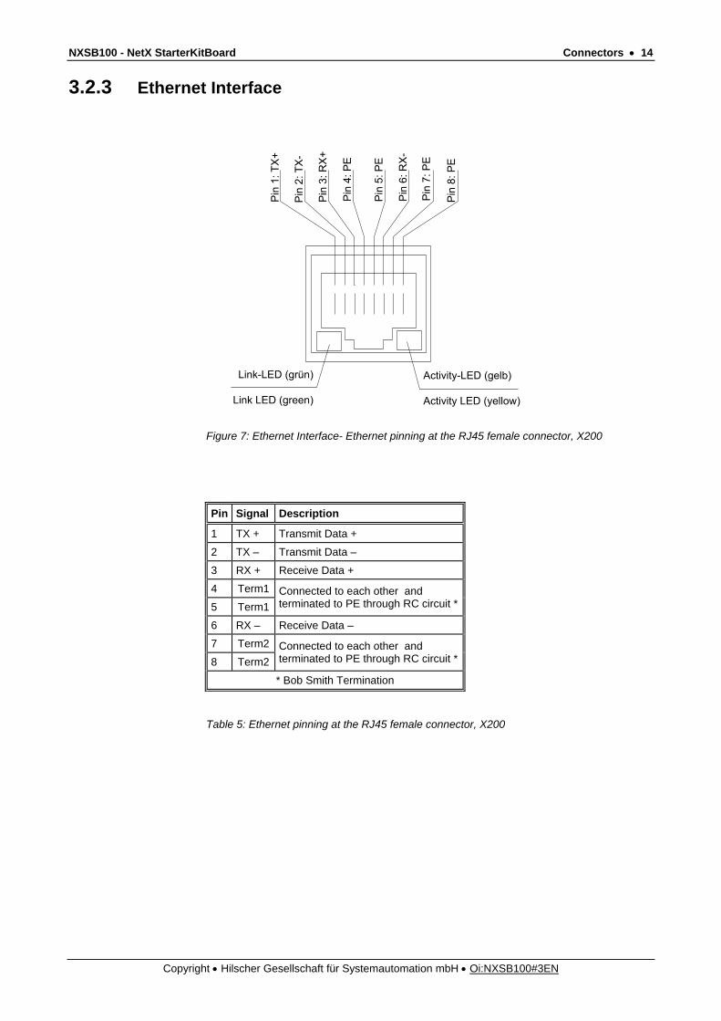
3.2.3 Ethernet Interface
Pin
1: T
X+
Pin
3: R
X+
Pin
4: P
E
Pin
5: P
E
Pin
6: R
X-
Pin
7: P
E
Pin
2: T
X-
Pin
8: P
E
Link-LED (grün)
Link LED (green)
Activity-LED (gelb)
Activity LED (yellow)
Figure 7: Ethernet Interface- Ethernet pinning at the RJ45 female connector, X200
Pin Signal Description
1 TX + Transmit Data +
2 TX – Transmit Data –
3 RX + Receive Data +
4 Term1
5 Term1 Connected to each other and terminated to PE through RC circuit *
6 RX – Receive Data –
7 Term2
8 Term2 Connected to each other and terminated to PE through RC circuit *
* Bob Smith Termination
Table 5: Ethernet pinning at the RJ45 female connector, X200
NXSB100 - NetX StarterKitBoard Connectors • 15
Copyright • Hilscher Gesellschaft für Systemautomation mbH • Oi:NXSB100#3EN
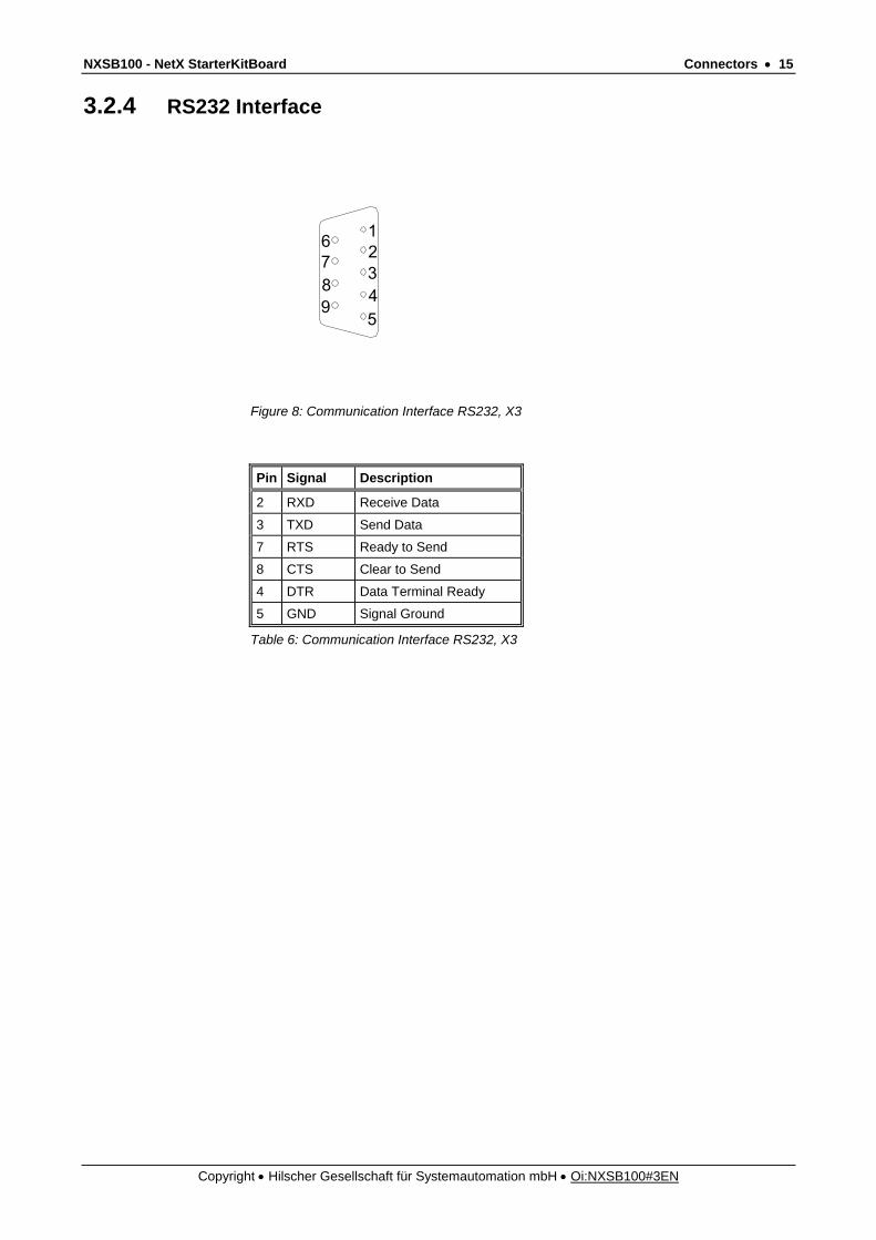
3.2.4 RS232 Interface
1
5
234
6789
Figure 8: Communication Interface RS232, X3
Pin Signal Description
2 RXD Receive Data
3 TXD Send Data
7 RTS Ready to Send
8 CTS Clear to Send
4 DTR Data Terminal Ready
5 GND Signal Ground
Table 6: Communication Interface RS232, X3

NXSB100 - NetX StarterKitBoard Connectors • 16
Copyright • Hilscher Gesellschaft für Systemautomation mbH • Oi:NXSB100#3EN
3.2.5 USB Interface
2
3
1
4
Figure 9: USB Interface female connector Type B, X2
Pin Name Description
1 USB_EXT USB Bus Power (+5V, supplied externally)
2 D- Data -
3 D+ Data +
4 GND Ground
Table 7: Pin out, X2
3.2.6 XMAC I/O signals Certain Real Time Ethernet applications (e.g. EtherCAT) may require additional synchronization signals. If such signals are required, XMAC I/O signals are used for that purpose, which are available at connector X201.
Pin Name Description
1 XM2_IO0 IO0 signal of XMAC2
2 XM2_IO1 IO1 signal of XMAC2
3 XM3_IO0 IO0 signal of XMAC3
4 XM3_IO1 IO1 signal of XMAC3
5 GND Ground
Table 8: XMAC I/Os, X201

NXSB100 - NetX StarterKitBoard Connectors • 17
Copyright • Hilscher Gesellschaft für Systemautomation mbH • Oi:NXSB100#3EN
3.3 Dual-Port-Memory, Extension-Bus, PIOs The NXSB 100 is equipped with a host interface Connector (X4), allowing access to the netX host interface, which can operate as a DPM Interface, an Expansion Bus or I/O Port. To allow quick and easy evaluation of the netX DPM mode, this connector can also be used to hook up the NXSB 100 to the NXSB-PCA adapter card (PCI), providing access to the netX virtual DPM through a memory window on a host PC.
Pin DPM Ext. Bus Prog. I/O
1 +3,3V +3,3V +3,3V
2 GND GND GND
3 CLKOUT CLKOUT CLKOUT
4 RSTOUT RSTOUT RSTOUT
5 +VSEXT +VSEXT +VSEXT
6 not connected
7 not connected
8 SEL_A19 EXT_A24 PI040
9 PI036 PI036 PI036
10 GND GND GND
11 DPM_INT EXT_IRQ PIO47
12 DPM_RDY EXT_RDY PIO46
13 DPM_RD EXT_RD PIO52
14 DPM_WRH EXT_WRH PIO44
15 DPM_WRL EXT_WRL PIO45
16 DPM_WIF EXT_ALE PIO35
17 DPM_BHE EXT_BHE PIO43
18 SEL_A18 EXT_CS3 PIO84
19 SEL_A16 EXT_CS2 PIO79
20 SEL_A17 EXT_CS1 PIO80
21 DPM_CS EXT_CS0 PIO51
22 GND GND GND
23 SELA_A15 EXT_A23 PIO72
24 SELA_A14 EXT_A22 PIO71
25 SELA_A13 EXT_A21 PIO68
26 SELA_A12 EXT_A20 PIO67
27 (DPM_A19) EXT_A19 PIO63
28 (DPM_A18) EXT_A18 PIO62
29 (DPM_A17) EXT_A17 PIO59
30 (DPM_A16) EXT_A16 PIO58
31 DPM_A15 EXT_A15 PIO55
32 DPM_A14 EXT_A14 PIO54
33 DPM_A13 EXT_A13 PIO48
34 DPM_A12 EXT_A12 PIO49
35 DPM_A11 EXT_A11 PIO50
36 DPM_A10 EXT_A10 PIO53
37 DPM_A9 EXT_A9 PIO56
Continued on next page.

NXSB100 - NetX StarterKitBoard Connectors • 18
Copyright • Hilscher Gesellschaft für Systemautomation mbH • Oi:NXSB100#3EN
Pin DPM Ext. Bus Prog. I/O
38 DPM_A8 EXT_A8 PIO57
39 DPM_A7 EXT_A7 PIO60
40 DPM_A6 EXT_A6 PIO61
41 DPM_A5 EXT_A5 PIO64
42 DPM_A4 EXT_A4 PIO65
43 DPM_A3 EXT_A3 PIO66
44 DPM_A2 EXT_A2 PIO69
45 DPM_A1 EXT_A1 PIO70
46 DPM_A0 EXT_A0 PIO73
47 DPM_D15 EXT_D15 PIO41
48 DPM_D14 EXT_D14 PIO42
49 DPM_D13 EXT_D13 PIO37
50 DPM_D12 EXT_D12 PIO38
51 DPM_D11 EXT_D11 PIO39
52 DPM_D10 EXT_D10 PIO33
53 DPM_D9 EXT_D9 PIO34
54 DPM_D8 EXT_D8 PIO32
55 DPM_D7 EXT_D7 PIO74
56 DPM_D6 EXT_D6 PIO75
57 DPM_D5 EXT_D5 PIO77
58 DPM_D4 EXT_D4 PIO77
59 DPM_D3 EXT_D3 PIO78
60 DPM_D2 EXT_D2 PIO81
61 DPM_D1 EXT_D1 PIO82
62 DPM_D0 EXT_D0 PIO83
63 +3,3V +3,3V +3,3V
64 GND GND GND
Table 9: Pinning Dual Port Memory Extension Bus, X4

NXSB100 - NetX StarterKitBoard Connectors • 19
Copyright • Hilscher Gesellschaft für Systemautomation mbH • Oi:NXSB100#3EN
3.4 AD Converter
Pin Signal Description
1 AD0_IN0 Analog Input, ADC0, Channel 0
2 AD0_IN1 Analog Input, ADC0, Channel 1
3 AD0_IN2 Analog Input, ADC0, Channel 2
4 AD0_IN3 Analog Input, ADC0, Channel 3
5 AD0_VREFP ADC Reference Voltage (+) for ADC 0 (typ. 3.3V)
6 AD0_VREFM ADC Reference Voltage (-) for ADC 0
7 AD_VDDIO ADC Supply Voltage (+3.3V)
8 AD_VSS Analog/signal ground for ADC
9 AD1_IN0 Analog Input, ADC1, Channel 0
10 AD1_IN1 Analog Input, ADC1, Channel 1
11 AD1_IN2 Analog Input, ADC1, Channel 2
12 AD1_IN3 Analog Input, ADC1, Channel 3
13 AD1_VREFP ADC Reference Voltage (+) for ADC 1 (typ. 3.3V)
14 AD1_VREFM ADC Reference Voltage (-) for ADC 1
15 AD_VDDIO ADC Supply Voltage (+3.3V)
16 AD_VSS Analog/signal ground for ADC
Table 10: Pinning ADC, X5
• The ADC Supply Voltage (AD_VDDIO) is provided by the NXSB100 and can be used to power additional user specific analog hardware (maximum current 150 mA).
Do not connect a power source to this pin!
• The ADC Reference Voltages (AD0_VREFP and AD1_VREFP) are used as a reference for the netX AD Converters. If no external reference is used, these pins should be connected to the AD_VDDIO pins as the ADCs will not provide reasonable data without a reference voltage.

NXSB100 - NetX StarterKitBoard Connectors • 20
Copyright • Hilscher Gesellschaft für Systemautomation mbH • Oi:NXSB100#3EN
3.5 JTAG Interface Through connector X1, located near the lower left corner of the board, the user has access to the JTAG interface of the integrated ARM CPU inside the netX. The JTAG port allows the connection of appropriate debugging devices, such as the “Tantino” from Hitex or the “RealView Multi-ICE” available from ARM The connector pin out follows the common standard for ARM JTAG ports. Pin ARM Signals netX Signals
1 VTref +3.3V
2 Vsupply +3.3V
3 nTRST JT_TRSTn
4 GND VSS
5 TDO JT_TDO
6 GND VSS
7 TMS JT_TMS
8 GND VSS
9 TCK JT_TCK
10 GND VSS
11 RTCK Not connected
12 GND VSS
13 TDI JT_TDI
14 GND VSS
15 nSRST PORn
16 GND VSS
17 DBGRQ Not connected
18 GND VSS
19 DBGACK Not connected
20 GND VSS
Table 11: JTAG Interface, X1

NXSB100 - NetX StarterKitBoard Software Tools • 21
Copyright • Hilscher Gesellschaft für Systemautomation mbH • Oi:NXSB100#3EN
4 Software Tools
4.1 Debug System Software - HiTOP
4.1.1 Minimum Project Requirements Besides HiTOP, the following tools and files are required in order to get a HiTOP project running on the netX platform.
HiTOP Environment and Gnu Compiler InitGnu File – The InitGnu assembly file contains the start-up code
required to get the user program to main to begin configuration and execution of OS tasks.
Header Files – Declares the function prototypes Source Files – Include your program code
4.1.2 Loading an Example Project with the HiTOP Environment We recommend to use an existing project file which contains all necessary settings. For this, start HiTOP and proceed as follows:
Depending on your board, open the corresponding project file using the Project > Open command:
Figure 10: Open Project
Click the Open button.
When using an example project file for the first time, you will be prompted with the following Tool selection dialog box:
NOTE: A lot of examples, tools and information can be found on our website, www.hilscher.com. Please follow netX Downloads.

NXSB100 - NetX StarterKitBoard Software Tools • 22
Copyright • Hilscher Gesellschaft für Systemautomation mbH • Oi:NXSB100#3EN
Figure 11: Tool Selection
Select Tantino for ARM 7-9 and click the Next button.
Figure 12: Port selection
Now the Tantino serial number (can be found on a sticker attached to the Tantino) has to be entered, and your PC and Tantino Device have to be connected by the supplied USB cable.
Click Next.

NXSB100 - NetX StarterKitBoard Software Tools • 23
Copyright • Hilscher Gesellschaft für Systemautomation mbH • Oi:NXSB100#3EN
If you haven’t yet obtained a full license, the following dialog will appear offering to purchase a full license, request a 30 day license or continue evaluation with the 60K limit:
Figure 13: License
Your HiTOP installation includes a code-size limited license for free. For more information on how to get a full license, refer to the How to get a License chapter of the HiTOP Licensing Procedure.
Click at the following button:
.
The following dialog box will be displayed:
Figure 14: Download Application
Click the OK button to load the application. If there are several
applications within a project, they will all be displayed here and can be loaded selectively.

NXSB100 - NetX StarterKitBoard Software Tools • 24
Copyright • Hilscher Gesellschaft für Systemautomation mbH • Oi:NXSB100#3EN
4.1.3 Defining a new Project with the HiTOP Environment There are two possibilities, to start with a new project. The first is to download and use the HiTop_Project_Template.zip file from our website, www.hilscher.com (netX > Downloads > netX Design Information, Documentation, Examples and Tools > Application Examples). The alternative choice is to create a new project as described here:
Define a new project with the Project > New command. Assign your project a name and select the folder where you wish the Project file to be stored.
Figure 15: New Project
Select your system from the Tool selection dialog box
Figure 16: Tool Selection
Click Next

NXSB100 - NetX StarterKitBoard Software Tools • 25
Copyright • Hilscher Gesellschaft für Systemautomation mbH • Oi:NXSB100#3EN
Select the controller derivative you are using and the ARM®
configuration from the Controller selection dialog box. If the controller type is not included in the list, select as Vendor = "Arm" and as controller type the core type your controller is based on.
Figure 17: Controller Selection
Click Next
Select the port you use from the Port selection dialog box.
Figure 18: Port Selection
Now the Tantino serial number (can be found on a sticker attached to the Tantino) has to be entered, and your PC and Tantino Device have to be connected by the supplied USB cable.
Click Next.

NXSB100 - NetX StarterKitBoard Software Tools • 26
Copyright • Hilscher Gesellschaft für Systemautomation mbH • Oi:NXSB100#3EN
If you haven’t yet obtained a full license, the following dialog will appear, offering to purchase a full license, request a 30 day license or continue evaluation with the 60K limit:
Figure 19: License
Your HiTOP installation includes a code-size limited license for free. For more information on how to get a full license, refer to the How to get a License chapter of the HiTOP Licensing Procedure.
Click at the following button:
.
Enter the startup script you would like to load. Use the Browse... buttons to search for the startup script.
Figure 20: Startup Script Selection

NXSB100 - NetX StarterKitBoard Software Tools • 27
Copyright • Hilscher Gesellschaft für Systemautomation mbH • Oi:NXSB100#3EN
Click Next.
4.1.4 Tool Settings Select the compiler tool chain you are using from the list box (“GNU C Compiler for ARM”). After selecing a supported compiler tool chain, the Tool Settings Button appears, allowing you to modify the tool settings.
Figure 21: Project Settings
The most important settings are the tool path and the names of the assembler, compiler and linker executables. NOTE: The tool path is a global setting that applies to all projects which use this tool chain!
Figure 22: Default Linker Settings
On the bottom of the dialog the Assembler, Compiler and Linker tabs allow to adjust default settings for the tools. The default settings are used when creating a new build configuration and although they are global settings, modifying them has no effect on existing build configurations in existing projects.

NXSB100 - NetX StarterKitBoard Software Tools • 28
Copyright • Hilscher Gesellschaft für Systemautomation mbH • Oi:NXSB100#3EN
The next step is to enter a new application. Click at the “New” button and enter the desired application name in the new line that now appears in the application window. Now close the dialog box by clicking the OK button and reopen it through the the Project > Settings menu
(this step is vital, as you won’t be able to edit any settings without it!)
Figure 23: Applications
4.1.5 Build Configuration The build configuration for the current project can be modified by selecting the project in the Project Settings dialog and the selecting the Tool Settings button.
Figure 24: General Settings

NXSB100 - NetX StarterKitBoard Software Tools • 29
Copyright • Hilscher Gesellschaft für Systemautomation mbH • Oi:NXSB100#3EN
However, before being able to modify the configuration, it has to be created first. A new build configuration can be derived from the default settings or from an existing build configuration. Users may want to use several build configurations to let them work with different settings or compiler options (debug and release version of the binary). To create a new configuration, klick on the “New” Button and enter a name for the build configuration. If other configurations already exist, they can be selected as templates from the drop down menu, otherwise only <none> can be selected, which leads to the use of the default parameters for the new configuration.
Figure 25: General Settings
Figure 26: New Build Configuration

NXSB100 - NetX StarterKitBoard Software Tools • 30
Copyright • Hilscher Gesellschaft für Systemautomation mbH • Oi:NXSB100#3EN
Once the configuration is created, it can be adapted through the four tabs (General, Assembler, Compiler, Linker) as shown below:
Figure 27: Linker Settings
The linker dialog allows defining a linker command line, a linker script file and a post build step. Users should be aware, that HiTOP currently doesn’t generate a file list which is provided to the linker.
The user has to take care that all files which are part of the project are listed in a file, provided to the linker. It is also possible to provide a file list as command line parameter. However, this is only recommended for simple projects with a small number of linked files. For large projects the command line length may exceed the maximum length if too much files must be linked together. Assembler > Assembler Options set to -marmv4t -gdwarf2 -mthumb-interwork Compiler > Preprocessor Definitions set to _NETX_HITOP_; __RCX__ Compiler-> Compiler Options set to -gdwarf-2 -Wall -O1 -mapcs -march=armv4t -mthumb-interwork -c -mthumb -fshort-enums NOTE: These settings could be different to the projects which are
available in the internet. In this case use the settings from the downloaded example.

NXSB100 - NetX StarterKitBoard Software Tools • 31
Copyright • Hilscher Gesellschaft für Systemautomation mbH • Oi:NXSB100#3EN
4.1.6 Linker Script File The main purpose of the linker script is to describe how the sections in the input files should be mapped into the output file, and to control the memory layout of the output file. In our linker script file we include the file “netX.lnk” This file contains the search directories for the linker and the needed modules. /*!!!!!!!!!!!!!!!!!!!!!!!!!!!!!!!!!!!!!!!!!!!!!!!!!!!!!!!!!!! The search dirs entries in the next lines refer to the path where the linker can find the library files for the gnu lib These are different depending on where you installed the GNU tools. Plaese add your specifik path if you get a linker error like: arm-hitex-elf-ld: cannot find -lgcc !!!!!!!!!!!!!!!!!!!!!!!!!!!!!!!!!!!!!!!!!!!!!!!!!!!!!!!!!!!*/ SEARCH_DIR("C:\Programme\Hitex\GnuToolPackageArm\arm-hitex-elf\lib\interwork\arm926ej-s") SEARCH_DIR("C:\Programme\Hitex\GnuToolPackageArm\lib\gcc\arm-hitex-elf\4.0.3\interwork\arm926ej-s") SEARCH_DIR("D:\Programme\Hitex\GnuToolPackageArm\arm-hitex-elf\lib\interwork\arm926ej-s") SEARCH_DIR("D:\Programme\Hitex\GnuToolPackageArm\lib\gcc\arm-hitex-elf\4.0.3\interwork\arm926ej-s") /* The next lines specify all program modules that need to be linked into the target file */ SEARCH_DIR("./Lib") INPUT ( ./Output/init_gnu.o ) INPUT ( ./Output/Config_netX_LoadFirm.o ) INPUT ( ./Output/ExampleApp_Body.o ) INPUT ( ./Output/ExampleApp_Functions.o ) INPUT ( ./Output/ExampleApp_Process.o ) INPUT ( ./Output/ExampleApp_Resources.o )
4.1.7 Build / Rebuild The build tool bar allows rebuilding your application. You can 1. Specify the target to build 2. Chose a build configuration 3. Compile the currently selected file 4. Compile the current file and link the current selected project 5. Rebuild (compile all files) the currently selected project The build toolbar is only enabled if the tool chain is fully configured and at least one build configuration is defined. NOTE: For more information about the HiTOP IDE please consult the delivered manuals in your HiTOP folder.
NXSB100 - NetX StarterKitBoard Software Tools • 32
Copyright • Hilscher Gesellschaft für Systemautomation mbH • Oi:NXSB100#3EN
4.2 netX Bootwizard You can download the latest Boot Wizard Version from our homepage www.hilscher.com ( netX > Downloads > netX Design Information, Documentation, Examples and Tools > Software).
The netX Boot Wizard is a graphical front-end for the generating and processing of netX boot images. The wizard’s primary use is to create bootable binary images from compiler output, like elf files, and write these images to the netX SPI flash memory. Further it offers functions to check and modify boot images, extract data and parameters from compiler output and generate standalone boot blocks.
This manual describes version 0.7. Please note that this version is a prerelease. Functions and their graphical representation are subject to change in later releases.
This chapter only provides short form information on the netX Boot Wizard main functions. Please also consult the full documentation included with the Boot Wizard files.
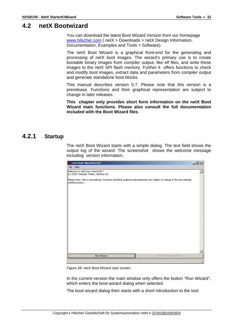
4.2.1 Startup The netX Boot Wizard starts with a simple dialog. The text field shows the output log of the wizard. The screenshot shows the welcome message including version information.
Figure 28: netX Boot Wizard start screen
In the current version the main window only offers the button "Run Wizard", which enters the boot wizard dialog when selected.
The boot wizard dialog then starts with a short introduction to the tool.

NXSB100 - NetX StarterKitBoard Software Tools • 33
Copyright • Hilscher Gesellschaft für Systemautomation mbH • Oi:NXSB100#3EN
Figure 29: netX Boot Wizard dialog
Click Next.
Figure 30: the operation mode menu
The function dialog now lets you select the action the wizard should perform. The first two items in the menu are described in the following chapters.
Click Next.

NXSB100 - NetX StarterKitBoard Software Tools • 34
Copyright • Hilscher Gesellschaft für Systemautomation mbH • Oi:NXSB100#3EN
4.2.2 Function “build bootimage” This function generates a boot image (a boot block with appended application data). The application data is extracted from a compiler output file, like an elf image. The dialog starts with the selection of the input file.
Figure 31: Build Bootimage, Input file Selection
Click Next.
The following dialog prompts for the source and destination devices and the toolset. • The source device specifies the device that will hold the bootimage
(parallel or serial flash).
• The destination device is the target of the boot process (sdram or internal RAM). The bootloader copies the data from the boot image to this device.
• The toolset is used to extract binary data and parameters from input images, like elf files.
NXSB100 - NetX StarterKitBoard Software Tools • 35
Copyright • Hilscher Gesellschaft für Systemautomation mbH • Oi:NXSB100#3EN
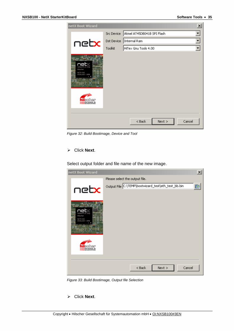
Figure 32: Build Bootimage, Device and Tool
Click Next.
Select output folder and file name of the new image.
Figure 33: Build Bootimage, Output file Selection
Click Next.

NXSB100 - NetX StarterKitBoard Software Tools • 36
Copyright • Hilscher Gesellschaft für Systemautomation mbH • Oi:NXSB100#3EN
Figure 34: Configuration completed
Click Finish. The image has now been written to the selected
destination path.
4.2.3 Function “flash bootimage to SPI flash” This function writes a boot image to the spi flash memory of the netX board. The dialog starts with the selection of the input file.
Figure 35: Flash Bootimage, Input file Selection

NXSB100 - NetX StarterKitBoard Software Tools • 37
Copyright • Hilscher Gesellschaft für Systemautomation mbH • Oi:NXSB100#3EN
Click Next. In the next Dialog select the SDRAM Type of your board.
Figure 36: SDRam Selection
Click Next.
Figure 37: Flash Bootimage, Configuration
Click Finish.
NXSB100 - NetX StarterKitBoard Software Tools • 38
Copyright • Hilscher Gesellschaft für Systemautomation mbH • Oi:NXSB100#3EN
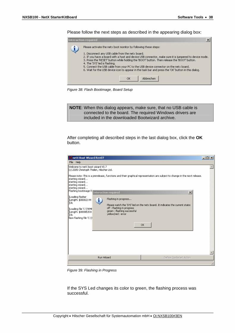
Please follow the next steps as described in the appearing dialog box:
Figure 38: Flash Bootimage, Board Setup
NOTE: When this dialog appears, make sure, that no USB cable is connected to the board. The required Windows drivers are included in the downloaded Bootwizard archive.
After completing all described steps in the last dialog box, click the OK button.
Figure 39: Flashing in Progress
If the SYS Led changes its color to green, the flashing process was successful.

NXSB100 - NetX StarterKitBoard Lists • 39
Copyright • Hilscher Gesellschaft für Systemautomation mbH • Oi:NXSB100#3EN
5 Lists 5.1 List of Figures Figure 1: netX Block Diagramm 5 Figure 2: Overview NXSB 100 7 Figure 3: Block Diagram NXSB 100 8 Figure 4: Power Supply, X100 11 Figure 5: PROFIBUS Interface (DSub female connector), X6 12 Figure 6: DeviceNet Interface (Combicon male connector, 5 pin), X7 13 Figure 7: Ethernet Interface- Ethernet pinning at the RJ45 female connector, X200 14 Figure 8: Communication Interface RS232, X3 15 Figure 9: USB Interface female connector Type B, X2 16 Figure 10: Open Project 21 Figure 11: Tool Selection 22 Figure 12: Port selection 22 Figure 13: License 23 Figure 14: Download Application 23 Figure 15: New Project 24 Figure 16: Tool Selection 24 Figure 17: Controller Selection 25 Figure 18: Port Selection 25 Figure 19: License 26 Figure 20: Startup Script Selection 26 Figure 21: Project Settings 27 Figure 22: Default Linker Settings 27 Figure 23: General Settings 28 Figure 24: General Settings 29 Figure 25: New Build Configuration 29 Figure 26: Linker Settings 30 Figure 27: netX Boot Wizard start screen 32 Figure 28: netX Boot Wizard dialog 33 Figure 29: the operation mode menu 33 Figure 30: Build Bootimage, Input file Selection 34 Figure 31: Build Bootimage, Device and Tool 35 Figure 32: Build Bootimage, Output file Selection 35 Figure 33: Configuration completed 36 Figure 34: Flash Bootimage, Input file Selection 36 Figure 35: SDRam Selection 37 Figure 36: Flash Bootimage, Configuration 37 Figure 37: Flash Bootimage, Board Setup 38 Figure 38: Flashing in Progress 38

NXSB100 - NetX StarterKitBoard Lists • 40
Copyright • Hilscher Gesellschaft für Systemautomation mbH • Oi:NXSB100#3EN
5.2 List of Tables Table 1: LEDs 9 Table 2: Power Supply, X100 11 Table 3: PROFIBUS Interface, X6 12 Table 4: DeviceNet Interface, X7 13 Table 5: Ethernet pinning at the RJ45 female connector, X200 14 Table 6: Communication Interface RS232, X3 15 Table 7: Pin out, X2 16 Table 8: XMAC I/Os, X201 16 Table 9: Pinning Dual Port Memory Extension Bus, X4 18 Table 10: Pinning ADC, X5 19 Table 11: JTAG Interface, X1 20


![Życie Techniczne. r.X nr.4 [ZT34 4] - bcpw.bg.pw.edu.plbcpw.bg.pw.edu.pl/Content/2130/zt34_nr4.pdf · Ogień ni spale i Złodziej nie ukradnie Woda nie zniszczy Pieniędzy złożonych](https://static.fdocuments.net/doc/165x107/5c76e9ac09d3f2c43b8b5689/zycie-techniczne-rx-nr4-zt34-4-bcpwbgpwedu-ogien-ni-spale-i-zlodziej.jpg)