Manual MOVIFIT® FC/MC – Application Module Cam Positioning ... · Warning of dangerous...
52
*21306192_1114* Drive Technology \ Drive Automation \ System Integration \ Services Manual MOVIFIT ® FC/MC – Application Module Cam Positioning Edition 11/2014 21306192/EN
Transcript of Manual MOVIFIT® FC/MC – Application Module Cam Positioning ... · Warning of dangerous...
*21306192_1114*Drive Technology \ Drive Automation \ System Integration \ Services
Manual
MOVIFIT® FC/MC – Application Module Cam Positioning
Edition 11/2014 21306192/EN

SEW-EURODRIVE—Driving the world

Contents
Manual – MOVIFIT® FC/MC – Application Module Cam Positioning 3
Contents1 General information .................................................................................................................. 5
1.1 About this documentation ............................................................................................... 51.2 Structure of the safety notes .......................................................................................... 5
1.2.1 Meaning of signal words ................................................................................. 51.2.2 Structure of section-related safety notes ........................................................ 51.2.3 Structure of embedded safety notes ............................................................... 6
1.3 Right to claim under warranty ........................................................................................ 61.4 Exclusion of liability ........................................................................................................ 61.5 Other applicable documentation .................................................................................... 71.6 Product names and trademarks ..................................................................................... 71.7 Copyright ........................................................................................................................ 7
2 Safety notes ............................................................................................................................... 82.1 General .......................................................................................................................... 82.2 Target group ................................................................................................................... 82.3 Designated use .............................................................................................................. 92.4 Bus systems ................................................................................................................... 92.5 Short designation ........................................................................................................... 9
3 System description ................................................................................................................. 103.1 Area of application ....................................................................................................... 103.2 Properties ..................................................................................................................... 10
4 Operating modes..................................................................................................................... 114.1 Feed-in / feed-out ......................................................................................................... 11
4.1.1 Operating principle........................................................................................ 114.1.2 Operating mode "Feed-in" ............................................................................ 124.1.3 Operating mode "Feed-out" .......................................................................... 13
4.2 Lifting/rotating ............................................................................................................... 144.2.1 Operating principle........................................................................................ 144.2.2 Functional description ................................................................................... 15
4.3 Jog mode ..................................................................................................................... 164.3.1 Operating principle........................................................................................ 164.3.2 Functional description ................................................................................... 16
5 Cycle diagrams........................................................................................................................ 185.1 Feed-in/feed-out ........................................................................................................... 185.2 Lifting/rotating ............................................................................................................... 195.3 Jog mode ..................................................................................................................... 20
6 Startup...................................................................................................................................... 216.1 Preparing startup .......................................................................................................... 216.2 Starting the application module .................................................................................... 216.3 Commencing startup .................................................................................................... 236.4 Process data configuration ........................................................................................... 246.5 Configuring monitoring functions .................................................................................. 256.6 Setting setpoints ........................................................................................................... 266.7 Downloading the program ............................................................................................ 28
2130
6192
/EN
– 1
1/20
14

Contents
Manual – MOVIFIT® FC/MC – Application Module Cam Positioning4
7 Operation and diagnostics ..................................................................................................... 297.1 Control via fieldbus with 1 process data word .............................................................. 29
7.1.1 Monitor mode ................................................................................................ 297.1.2 Control mode ................................................................................................ 30
7.2 Control via fieldbus with 3 process data words ............................................................ 317.2.1 Monitor mode ................................................................................................ 317.2.2 Control mode ................................................................................................ 32
7.3 Control via fieldbus with 6 process data words ............................................................ 337.3.1 Monitor mode ................................................................................................ 337.3.2 Control mode ................................................................................................ 34
7.4 Diagnostics with the S12 safety option ........................................................................ 357.4.1 Safety notes .................................................................................................. 357.4.2 Description .................................................................................................... 357.4.3 S12 diagnostics view .................................................................................... 357.4.4 Structure of process data.............................................................................. 36
7.5 Extended process data word ........................................................................................ 38
8 Data management.................................................................................................................... 398.1 Safety notes ................................................................................................................. 398.2 Activating data management ........................................................................................ 398.3 Structure of process data ............................................................................................. 41
9 Terminal assignment............................................................................................................... 429.1 MOVIFIT® FC with "Technology" function level ............................................................ 429.2 MOVIFIT® MC with "Technology" function level ........................................................... 42
10 Process data ............................................................................................................................ 4310.1 Process data interface with the PLC with 1 process data word ................................... 43
10.1.1 Overview ....................................................................................................... 4310.1.2 Process output data ...................................................................................... 4310.1.3 Process input data ........................................................................................ 43
10.2 Process data interface with the PLC with 3 process data words ................................. 4410.2.1 Overview ....................................................................................................... 4410.2.2 Process output data ...................................................................................... 4510.2.3 Process input data ........................................................................................ 46
10.3 Process data interface with the PLC with 6 process data words ................................. 4610.3.1 Overview ....................................................................................................... 4610.3.2 Process output data ...................................................................................... 4710.3.3 Process input data ........................................................................................ 48
Index ......................................................................................................................................... 49
2130
6192
/EN
– 1
1/20
14

1General informationAbout this documentation
Manual – MOVIFIT® FC/MC – Application Module Cam Positioning 5
1 General information1.1 About this documentation
This documentation is an integral part of the product. The documentation is intended for all employees who perform assembly, installation, startup, and service work on the product.Make sure this documentation is accessible and legible. Ensure that persons respon-sible for the system and its operation, as well as persons who work independently on the unit, have read through the entire documentation and understood it. If you are un-clear about any of the information in this documentation, or if you require further infor-mation, contact SEW-EURODRIVE.
1.2 Structure of the safety notes1.2.1 Meaning of signal words
The following table shows the grading and meaning of the signal words for safety notes.
Signal word Meaning Consequences if disregarded
DANGER Imminent hazard Severe or fatal injuries.
WARNING Possible dangerous situation Severe or fatal injuries
CAUTION Possible dangerous situation Minor injuries
NOTICE Possible damage to property Damage to the drive system or its environment.
INFORMATION Useful information or tip: Sim-plifies handling of the drive sys-tem.
1.2.2 Structure of section-related safety notesSection-related safety notes do not apply to a specific action but to several actions pertaining to one subject. The hazard symbols used either indicate a general hazard or a specific hazard.Section-related safety notes are structured as follows:
SIGNAL WORD
Type and source of hazard.Possible consequence(s) if disregarded.• Measure(s) to prevent hazard.
Meaning of the hazard symbols
The hazard symbols in the safety notes have the following meaning:
Hazard symbol Meaning
General hazard
2130
6192
/EN
– 1
1/20
14

1 General informationRight to claim under warranty
Manual – MOVIFIT® FC/MC – Application Module Cam Positioning6
Hazard symbol Meaning
Warning of dangerous electrical voltage
Warning of hot surfaces
Warning of risk of crushing
Warning of suspended load
Warning of automatic restart
1.2.3 Structure of embedded safety notesEmbedded safety notes are directly integrated into the instructions just before the de-scription of the dangerous action.Embedded safety notes are structured as follows:• SIGNAL WORD Type and source of hazard.
Possible consequence(s) if disregarded.
– Measure(s) to prevent hazard.
1.3 Right to claim under warrantyA requirement of fault-free operation and fulfillment of any rights to claim under limited warranty is that you adhere to the information in the documentation at hand. There-fore, read the documentation before you start working with the software and the con-nected units from SEW-EURODRIVE.Make sure that the documentation is available to persons responsible for the machi-nery and its operation as well as to persons who work independently on the units. Also ensure that the documentation is legible.
1.4 Exclusion of liabilityYou must comply with the information contained in this documentation to ensure safe operation and to achieve the specified product characteristics and performance fea-tures. SEW-EURODRIVE assumes no liability for injury to persons or damage to equipment or property resulting from non-observance of these operating instructions. In such cases, any liability for defects is excluded.
2130
6192
/EN
– 1
1/20
14

1General informationOther applicable documentation
Manual – MOVIFIT® FC/MC – Application Module Cam Positioning 7
1.5 Other applicable documentationThis document supplements the MOVIFIT® FC/MC operating instructions and limits the application notes according to the following information. Use this documentation only in connection with the MOVIFIT® FC/MC operating instructions.
1.6 Product names and trademarksThe brands and product names in this documentation are trademarks or registered trademarks of their respective titleholders.
1.7 Copyright© 2014 SEW‑EURODRIVE. All rights reserved.Unauthorized reproduction, modification, distribution or any other use of the whole or any part of this documentation is strictly prohibited.
2130
6192
/EN
– 1
1/20
14

2 Safety notesGeneral
Manual – MOVIFIT® FC/MC – Application Module Cam Positioning8
2 Safety notes2.1 General
The following basic safety notes are intended to prevent injury to persons and damage to property. The user must ensure that the basic safety notes are read and observed.Ensure that persons responsible for the machinery and its operation as well as per-sons who work independently have read through the documentation carefully and un-derstood it. If you are unclear about any of the information in this documentation or if you require further information, please contact SEW-EURODRIVE.The following safety notes refer to the use of the software. Also observe the supple-mentary safety notes in this documentation and in the documentation for the connec-ted units from SEW-EURODRIVE.This document does not replace the detailed documentation for the connected units. This documentation assumes that the user has access to and is familiar with the docu-mentation for all connected units from SEW-EURODRIVE.Never install or operate damaged products. Report any damage to the shipping com-pany immediately.Depending on the degree of protection, units may have live, uninsulated, and some-times moving or rotating parts, as well as hot surfaces during operation.Removing required covers without authorization, improper use or incorrect installation and operation may result in severe injury to persons, or damage to machinery. Consult the documentation for further information.
2.2 Target groupWork with the software in this solution may only be performed by adequately qualified personnel. Qualified personnel in this context are persons who have the following qualifications:
• Appropriate training in their relevant field.• Knowledge of this documentation and other applicable documentation.• SEW‑EURODRIVE recommends additional product training for products that are
operated using this software.All mechanical work on connected units is to be performed exclusively by adequately qualified personnel. Qualified personnel in the context of this documentation are per-sons familiar with the design, mechanical installation, troubleshooting and servicing of the product, who possess the following qualifications:• Training in mechanical engineering, e.g. as a mechanic or mechatronics technician
(final examinations must have been passed).• Knowledge of this documentation and other applicable documentation.All electrical work on connected units is to be performed exclusively by adequately qualified electricians. Qualified electricians in the context of this documentation are persons familiar with electrical installation, startup, troubleshooting and servicing of the product, who possess the following qualifications:
• Training in electrical engineering, e.g. as an electrician or mechatronics technician (final examinations must have been passed).
• Knowledge of this documentation and other applicable documentation.
2130
6192
/EN
– 1
1/20
14

2Safety notesDesignated use
Manual – MOVIFIT® FC/MC – Application Module Cam Positioning 9
• Knowledge of the relevant safety regulations and laws.• Knowledge of all other standards, directives and laws named in this documenta-
tion.The above-mentioned persons must have the express authorization of the company to operate, program, configure, label and ground units, systems and circuits in accord-ance with the standards of safety technology.All work in the areas of transportation, storage, operation and waste disposal must be carried out by persons who are trained appropriately.
2.3 Designated useThe application module cam positioning is used to control cam positioning systems with MOVIFIT®.The cam positioning application module can be implemented with the following MOVIFIT® units:• MOVIFIT® FC with "Technology" function level• MOVIFIT® MC with "Technology" function level
2.4 Bus systemsA bus system makes it possible to adapt frequency inverters and/or motor starters to the particulars of the machinery within wide limits. This results in the risk that a change of parameters that cannot be detected externally can result in unexpected, though not uncontrolled, system behavior.
2.5 Short designationThe following short designations are used in this documentation.
Type designation Short designation
Application module cam positioning Application module
2130
6192
/EN
– 1
1/20
14

3 System descriptionArea of application
Manual – MOVIFIT® FC/MC – Application Module Cam Positioning10
3 System description3.1 Area of application
The application module is based on the "rapid/creep speed positioning" principle and can be used in the following applications:
• Roller and chain conveyors• Lifting table applications• Rotary table applicationsThe following operating modes are supported:
• Feed-in
• Feed-out• Lifting/rotating• Jog mode
3.2 PropertiesThis application module has the following characteristics:
• Bidirectional rapid/creep speed positioning to one limit switch pair at each end
• Jog mode or positioning mode
• Control via fieldbus
• 3 run time monitoring functions for positioning
• Monitoring of the creep speed when the stop sensor is reached
• Data management• Diagnostics with the S12 safety option• User-guided startup and diagnostics
2130
6192
/EN
– 1
1/20
14
4Operating modesFeed-in / feed-out
Manual – MOVIFIT® FC/MC – Application Module Cam Positioning 11
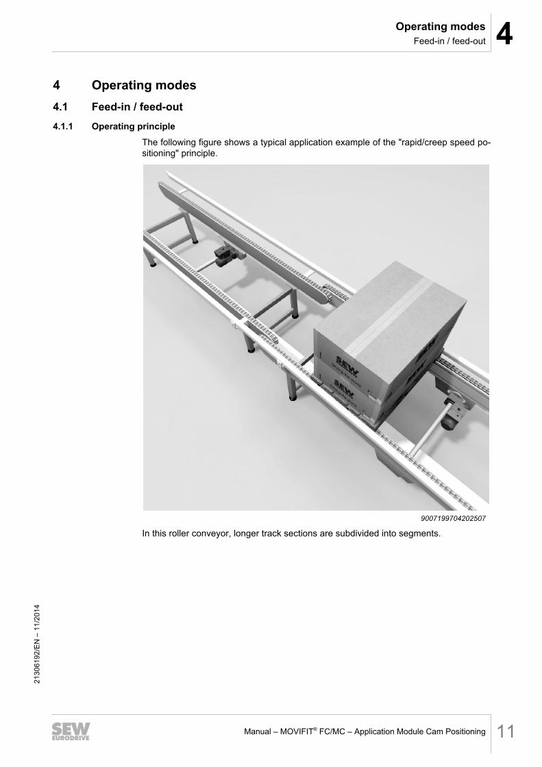
4 Operating modes4.1 Feed-in / feed-out4.1.1 Operating principle
The following figure shows a typical application example of the "rapid/creep speed po-sitioning" principle.
9007199704202507
In this roller conveyor, longer track sections are subdivided into segments.
2130
6192
/EN
– 1
1/20
14
4 Operating modesFeed-in / feed-out
Manual – MOVIFIT® FC/MC – Application Module Cam Positioning12
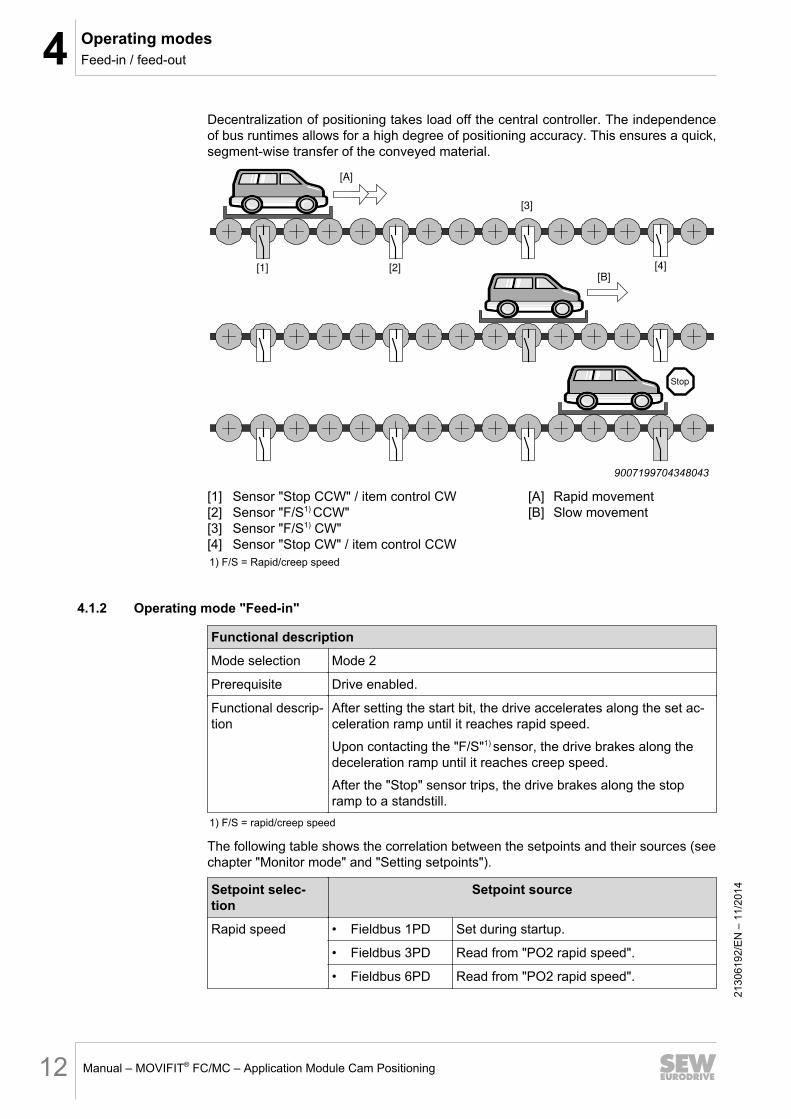
Decentralization of positioning takes load off the central controller. The independence of bus runtimes allows for a high degree of positioning accuracy. This ensures a quick, segment-wise transfer of the conveyed material.
Stop
[A]
[1] [2]
[3]
[4][B]
9007199704348043
[1] Sensor "Stop CCW" / item control CW [A] Rapid movement[2] Sensor "F/S1) CCW" [B] Slow movement[3] Sensor "F/S1) CW"[4] Sensor "Stop CW" / item control CCW1) F/S = Rapid/creep speed
4.1.2 Operating mode "Feed-in"
Functional description
Mode selection Mode 2
Prerequisite Drive enabled.
Functional descrip-tion
After setting the start bit, the drive accelerates along the set ac-celeration ramp until it reaches rapid speed.
Upon contacting the "F/S"1) sensor, the drive brakes along the deceleration ramp until it reaches creep speed.
After the "Stop" sensor trips, the drive brakes along the stop ramp to a standstill.
1) F/S = rapid/creep speed
The following table shows the correlation between the setpoints and their sources (see chapter "Monitor mode" and "Setting setpoints").
Setpoint selec-tion
Setpoint source
Rapid speed • Fieldbus 1PD Set during startup.
• Fieldbus 3PD Read from "PO2 rapid speed".
• Fieldbus 6PD Read from "PO2 rapid speed".
2130
6192
/EN
– 1
1/20
14

4Operating modesFeed-in / feed-out
Manual – MOVIFIT® FC/MC – Application Module Cam Positioning 13
Setpoint selec-tion
Setpoint source
Creep speed • Fieldbus 1PD Set during startup.
• Fieldbus 3PD Set during startup.
• Fieldbus 6PD Set via "PO3 creep speed".
Acceleration ramp • Fieldbus 1PD Set during startup.
• Fieldbus 3PD Read from "PO3 ramp".
• Fieldbus 6PD Read from "PO4 ramp".
Deceleration ramp • Fieldbus 1PD Set during startup.
• Fieldbus 3PD Read from "PO3 ramp".
• Fieldbus 6PD Read from "PO5 ramp down".
Stop ramp • Fieldbus 1PD Set during startup.
• Fieldbus 3PD Set during startup.
• Fieldbus 6PD Read from "PO6 ramp stop".
4.1.3 Operating mode "Feed-out"
Functional description
Mode selection Mode 3
Prerequisite Drive enabled.
Functional descrip-tion
After setting the start bit, the drive accelerates along the set ac-celeration ramp until it reaches rapid speed.
After the start bit is reset, the drive brakes along the decelera-tion ramp to a standstill.
The following table shows the correlation between the setpoints and their sources (see chapter "Monitor mode" and "Setting setpoints").
Setpoint selec-tion
Setpoint source
Rapid speed • Fieldbus 1PD Set during startup.
• Fieldbus 3PD Read from "PO2 rapid speed".
• Fieldbus 6PD Read from "PO2 rapid speed".
Acceleration ramp • Fieldbus 1PD Set during startup.
• Fieldbus 3PD Read from "PO3 ramp".
• Fieldbus 6PD Read from "PO4 ramp".
Deceleration ramp • Fieldbus 1PD Set during startup.
• Fieldbus 3PD Read from "PO3 ramp".
• Fieldbus 6PD Read from "PO5 ramp down".
2130
6192
/EN
– 1
1/20
14

4 Operating modesLifting/rotating
Manual – MOVIFIT® FC/MC – Application Module Cam Positioning14
4.2 Lifting/rotating4.2.1 Operating principle
The following figure shows a typical application example of a lifting station.
9007199704825483
For rotating and lifting, positioning is performed according to the same principle as for inward conveyance.Once positioning in one direction has been performed, however, the drive cannot be started in the same direction again. Starting in the same direction is inhibited by the "In position" message. This prevents unintentional travel against the mechanical stop.
DANGERRisk of crushing if the load falls.
Severe or fatal injuries.
• Do not stand under the load.
• Secure the danger zone.
2130
6192
/EN
– 1
1/20
14

4Operating modesLifting/rotating
Manual – MOVIFIT® FC/MC – Application Module Cam Positioning 15
Stop
[A]
[B]
[3]
[4]
[2]
[1]
9007199704833547
[1] Sensor "Stop CCW" / item control CW [A] Rapid movement[2] Sensor "F/S1) CCW" [B] Slow movement[3] Sensor "F/S1) CW"[4] Sensor "Stop CW" / item control CCW1) F/S = Rapid/creep speed
4.2.2 Functional description
Functional description
Mode selection Mode 4
Prerequisite Drive enabled.
Functional descrip-tion
After setting the start bit, the drive accelerates along the set ac-celeration ramp until it reaches rapid speed.
Upon contacting the "F/S"1) sensor, the drive brakes along the set deceleration ramp until it reaches creep speed.
After the "Stop" sensor trips, the drive brakes along the set stop ramp to a standstill.
Re-start in the same direction is blocked.1) F/S = Rapid/creep speed
The following table shows the correlation between the setpoints and their sources (see chapter "Monitor mode" and "Setting setpoints").
Setpoint selec-tion
Setpoint source
Rapid speed • Fieldbus 1PD Set during startup.
• Fieldbus 3PD Read from "PO2 rapid speed".
• Fieldbus 6PD Read from "PO2 rapid speed".
Creep speed • Fieldbus 1PD Set during startup.
• Fieldbus 3PD Set during startup.
• Fieldbus 6PD Set via "PO3 creep speed".
Acceleration ramp • Fieldbus 1PD Set during startup.
• Fieldbus 3PD Read from "PO3 ramp".
• Fieldbus 6PD Read from "PO4 ramp".
2130
6192
/EN
– 1
1/20
14

4 Operating modesJog mode
Manual – MOVIFIT® FC/MC – Application Module Cam Positioning16
Setpoint selec-tion
Setpoint source
Deceleration ramp • Fieldbus 1PD Set during startup.
• Fieldbus 3PD Read from "PO3 ramp".
• Fieldbus 6PD Read from "PO5 ramp down".
Stop ramp • Fieldbus 1PD Set during startup.
• Fieldbus 3PD Set during startup.
• Fieldbus 6PD Read from "PO6 ramp stop".
4.3 Jog mode4.3.1 Operating principle
In jog mode, you can move the drive independently of the other operating modes of the system.In jog mode, you can set the control bits "Jog+" or "Jog-" to move the drive clockwise or counterclockwise. It is not necessary to set the start bit.Speed and ramps are specified dynamically via the corresponding process data words.
4.3.2 Functional description
Functional description
Mode selection Mode 1
Prerequisite Drive enabled.
Functional descrip-tion
As long as the "positive" (jog+) signal is set, the drive rotates clockwise. As long as the "negative" (jog-) signal is set, the drive rotates counterclockwise. The drive stops if none or both signals are set.
Acceleration and deceleration depend on the set acceleration and deceleration ramp time.
The following table shows the correlation between the setpoints and their sources (see chapter "Monitor mode" and "Setting setpoints").
Setpoint selec-tion
Setpoint source
Rapid speed • Fieldbus 1PD Set during startup.
• Fieldbus 3PD Read from "PO2 rapid speed".
• Fieldbus 6PD Read from "PO2 rapid speed".
Acceleration ramp • Fieldbus 1PD Set during startup.
• Fieldbus 3PD Read from "PO3 ramp".
• Fieldbus 6PD Read from "PO4 ramp".
2130
6192
/EN
– 1
1/20
14

4Operating modesJog mode
Manual – MOVIFIT® FC/MC – Application Module Cam Positioning 17
Setpoint selec-tion
Setpoint source
Deceleration ramp • Fieldbus 1PD Set during startup.
• Fieldbus 3PD Read from "PO3 ramp".
• Fieldbus 6PD Read from "PO5 ramp down".
2130
6192
/EN
– 1
1/20
14

5 Cycle diagramsFeed-in/feed-out
Manual – MOVIFIT® FC/MC – Application Module Cam Positioning18
5 Cycle diagrams5.1 Feed-in/feed-out
The following figure shows the actual speed of the drive against the status of the input and output signals during feed-in or feed-out conveying.
n
[1]
[2]
[3]
[4]
[5]
[6]
[7]
[8]
[9]
1234
9007199704374795
n Actual speed[1] "Mode" input signal[2] "Start" input signal[3] "Positive" input signal[4] "Start detected" output signal[5] "Sensor "F/S1) CW" input signal[6] "Sensor stop CW" input signal[7] "Rapid speed active" output signal[8] "Creep speed active" output signal[9] "In position CW" output signal/top1) F/S = Rapid/creep speed
2130
6192
/EN
– 1
1/20
14

5Cycle diagramsLifting/rotating
Manual – MOVIFIT® FC/MC – Application Module Cam Positioning 19
5.2 Lifting/rotatingThe following figure shows the actual speed of the drive against the status of the input and output signals during lifting or rotating.
1234
n
[1]
[2]
[3]
[4]
[5]
[6]
[7]
[8]
[9]
[10]
[11]
[12]
[13]
450530955
n Actual speed [7] "Sensor stop CW" input signal[1] "Mode" input signal [8] "Sensor F/S CCW" input signal[2] "Start" input signal [9] "Sensor stop CCW" input signal[3] "Positive" input signal [10] "Rapid speed active" output signal[4] "Negative" input signal [11] "Creep speed active" output signal[5] "Start detected" output signal [12] "In position CW" output signal/top[6] "Sensor F/S CW" input signal [13] "In position CCW" output signal/bottom
2130
6192
/EN
– 1
1/20
14

5 Cycle diagramsJog mode
Manual – MOVIFIT® FC/MC – Application Module Cam Positioning20
5.3 Jog modeThe following figure shows the actual speed of the drive against the status of the input and output signals in jog mode.
1234
[1]
n
[2]
[3]
[4]
450541579
n Actual speed[1] "Mode" input signal[2] "Positive" input signal[3] "Negative" input signal[4] "Rapid speed active" output signal
2130
6192
/EN
– 1
1/20
14

6StartupPreparing startup
Manual – MOVIFIT® FC/MC – Application Module Cam Positioning 21
6 Startup6.1 Preparing startup
Perform the following steps before startup:
1. Connect MOVIFIT® FM/MC to your PC or laptop.
2. Install MOVITOOLS® MotionStudio engineering software on your PC or laptop.
3. Start MOVITOOLS® MotionStudio engineering software.
For more information on starting the MOVITOOLS® MotionStudio engineering soft-ware, please refer to the "MOVITOOLS® MotionStudio" manual.
6.2 Starting the application moduleProceed as follows:
ü MOVITOOLS® Motion Studio engineering software is started.
1. Select the relevant unit nodes.
2. Right-click to open the context menu.
3. Select the following menu command [Application modules] / [Cam positioning].
9007199705899147
ð The start window of the application module is displayed.
2130
6192
/EN
– 1
1/20
14
6 StartupStarting the application module
Manual – MOVIFIT® FC/MC – Application Module Cam Positioning22
[1]
[4][5][6]
[2]
[3]
18014398960667659
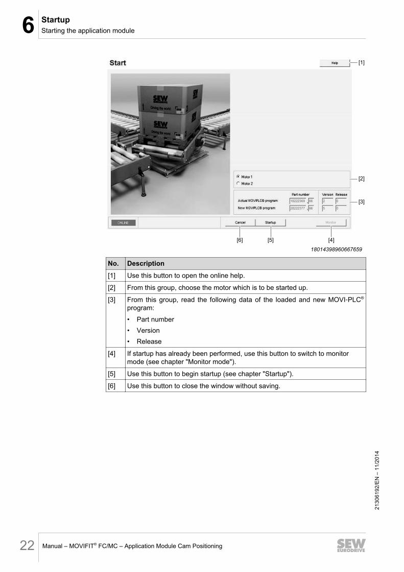
No. Description
[1] Use this button to open the online help.
[2] From this group, choose the motor which is to be started up.
[3] From this group, read the following data of the loaded and new MOVI‑PLC®
program:
• Part number• Version• Release
[4] If startup has already been performed, use this button to switch to monitor mode (see chapter "Monitor mode").
[5] Use this button to begin startup (see chapter "Startup").
[6] Use this button to close the window without saving.21
3061
92/E
N –
11/
2014

6StartupCommencing startup
Manual – MOVIFIT® FC/MC – Application Module Cam Positioning 23
6.3 Commencing startupProceed as follows:
1. Click the [Startup] button of the "Start" window (see chapter "Starting the applica-tion module").
ð The following window is displayed. The window shows the number and order of the startup steps.
[1]
[4]
[3]
[2]
9007199705935243
No. Description
[1] Click on the button in this group to switch to the window for selecting the type of control of the application module.
[2] Click on the button in this group to switch to the window for activating the run-time and creep speed monitoring functions.
[3] Click on the button in this group to switch to the window for setting the set-points for speed and ramps.
INFORMATION This selection is not possible for fieldbus control with 6 proc-ess data words. The reason is that all setpoints are specified via fieldbus when selecting this setting.
[4] Use this button in the group to switch to the window to download the MOVI‑PLC® program and to transfer the set parameters to the MOVIFIT®
FC/MC.
2130
6192
/EN
– 1
1/20
14

6 StartupProcess data configuration
Manual – MOVIFIT® FC/MC – Application Module Cam Positioning24
6.4 Process data configurationProceed as follows:
1. Click the [Startup] button of the "Startup" window in the "Process data configura-tion" group (see chapter "Commencing startup").
ð The following window is displayed.
[1]
[3]
[2]
[4] [5]
9007199705943051
No. Description
[1] In this group, select the control type of the application module.
[2] In this group, you can configure an extended process data word.The extended process data word is set to the following position when the fol-lowing process data words are selected:
• With 1 process data word: to the second position as second process data word
• With 3 process data words: to the fourth position as fourth process data word
• With 6 process data words: to the seventh position as seventh process data word
[3] In this group, you can activate the "S12 diagnostics". If "S12 diagnostics" is ac-tivated, the process data (3 PD) are transferred automatically to the existing configuration.
[4] Use this button to go to the next step.
[5] Use this button to set the fields to their default settings.
2. Select the type of application module control in group [1].
3. To go to the next step, use the button [4].
2130
6192
/EN
– 1
1/20
14

6StartupConfiguring monitoring functions
Manual – MOVIFIT® FC/MC – Application Module Cam Positioning 25
6.5 Configuring monitoring functionsThe following window is displayed. In this window, different monitoring functions can be activate or set.
[4]
[5]
[1]
[3]
[2]
[4] [5]
9007201299070859
No. Description
[1] In this group, you can change the logic (NC contact/NO contact) of the follow-ing sensors:
• Sensor "F/S1) CW"
• Sensor "stop CW"• Sensor "F/S1) CCW"• Sensor "stop CCW"
[2] In this group, enter the maximum deviation of the actual speed from the creep speed when the "Stop" sensor trips.Range of values: 20... 50... 100 rpm (0 = inactive).
[3] Enter the maximum time interval between start signal and reaching the sensor "item control" in this edit box.Range of values: 0... 0... 1000000 ms (0 = inactive).
[4] Enter the maximum time interval between start signal and the tripping of the sensor for rapid/creep speed (F/S) in this edit box. Range of values: 0... 0... 1000000 ms (0 = inactive).
2130
6192
/EN
– 1
1/20
14

6 StartupSetting setpoints
Manual – MOVIFIT® FC/MC – Application Module Cam Positioning26
No. Description
[5] Enter the maximum time interval between start signal and the tripping of the sensor "stop" in this edit box.Range of values: 0... 0... 1000000 ms (0 = inactive).
[6] Use this button to set the fields to their default settings.
[7] Use this button to go to the next step.1) F/S = Rapid/creep speed
INFORMATIONExceeding the limit value causes the drive to stop.
• Before re-starting the drive, you must acknowledge the error with a reset.
1. Select the required monitoring functions. Note that setting the value to 0 deacti-vates the monitoring function.
2. To go to the next step, use the button [7].
6.6 Setting setpointsThe following window is displayed.
[6] [7]
[4]
[5]
[3]
[1]
[2]
131969079151) X = 1 / 3 / 6 process data words depending on the selected type of control.
No. Description
[1] Enter the setpoint speed of the rapid speed in [rpm] in this edit box. Range of values: 0... 1500... 3000 rpm.
INFORMATION These parameters are not available for fieldbus control with 3PD.
[2] Enter the setpoint speed of the creep speed in [rpm] in this edit box. Range of values: 0... 750... 3000 rpm.
2130
6192
/EN
– 1
1/20
14

6StartupSetting setpoints
Manual – MOVIFIT® FC/MC – Application Module Cam Positioning 27
No. Description
[3] Enter the acceleration ramps for all acceleration phases in [ms] in this edit box. Range of values: 0... 2000... 20000 ms.The acceleration ramp times are based on a setpoint step change of:
• 3000 rpm for 2-pole motors• 1500 rpm for 4-pole motors• 1000 rpm for 6-pole motors
INFORMATION These parameters are not available for fieldbus control with 3PD.
[4] Enter the acceleration ramps for all deceleration phases in [ms] in this edit box. Range of values: 0... 2000... 20000 ms.The acceleration ramp times are based on a setpoint step change of:
• 3000 rpm for 2-pole motors• 1500 rpm for 4-pole motors• 1000 rpm for 6-pole motors
INFORMATION These parameters are not available for fieldbus control with 3PD.
[5] Enter the deceleration ramp times after passing the sensor "stop" in [ms] in this edit box. Range of values: 0... 500... 20000 ms.The deceleration ramp times are based on a setpoint step change of:
• 3000 rpm for 2-pole motors• 1500 rpm for 4-pole motors• 1000 rpm for 6-pole motors
[6] Use this button to set the fields to their default settings.
[7] Use this button to go to the next step.
1. Select the required setpoints.
2. To go to the next step, use the button [7].
2130
6192
/EN
– 1
1/20
14

6 StartupDownloading the program
Manual – MOVIFIT® FC/MC – Application Module Cam Positioning28
6.7 Downloading the programThe following window is displayed.
[4][3][2][1]
9007199706349451
No. Description
[1] In this group, the following data of the loaded and new MOVI‑PLC® program are displayed:
• Part number• Version• Release
[2] By activating this check box, the MOVI‑PLC® program is downloaded.
[3] In this group, status information of the CST tool1) are displayed.
[4] Use this button to transfer the MOVI‑PLC® program to the MOVIFIT® FC/MC.1) CST tool = CoDeSys service tool
1. Click the button [4].
ð The program is transferred to the MOVIFIT® FC/MC.
ð The software switches to the monitor mode of the selected control (see chapter "Operation and diagnostics").
2130
6192
/EN
– 1
1/20
14
7Operation and diagnosticsControl via fieldbus with 1 process data word
Manual – MOVIFIT® FC/MC – Application Module Cam Positioning 29
7 Operation and diagnostics7.1 Control via fieldbus with 1 process data word7.1.1 Monitor mode
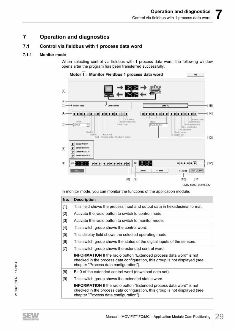
When selecting control via fieldbus with 1 process data word, the following window opens after the program has been transferred successfully.
[1]
[4]
[3]
[2]
[5]
[13]
[12]
[14]
[15]
[6]
[7]
[11][10][9][8]
9007199706494347
In monitor mode, you can monitor the functions of the application module.
No. Description
[1] This field shows the process input and output data in hexadecimal format.
[2] Activate the radio button to switch to control mode.
[3] Activate the radio button to switch to monitor mode.
[4] This switch group shows the control word.
[5] This display field shows the selected operating mode.
[6] This switch group shows the status of the digital inputs of the sensors.
[7] This switch group shows the extended control word.
INFORMATION If the radio button "Extended process data word" is not checked in the process data configuration, this group is not displayed (see chapter "Process data configuration").
[8] Bit 0 of the extended control word (download data set).
[9] This switch group shows the extended status word.
INFORMATION If the radio button "Extended process data word" is not checked in the process data configuration, this group is not displayed (see chapter "Process data configuration").
2130
6192
/EN
– 1
1/20
14
7 Operation and diagnosticsControl via fieldbus with 1 process data word
Manual – MOVIFIT® FC/MC – Application Module Cam Positioning30
No. Description
[10] Use this button to switch to the diagnostics view (see chapter "S12 diagnos-tics").
INFORMATION If the radio button "S12 diagnostics" is not checked in the process data configuration, this button is not displayed (see chapter "Process data configuration").
[11] Use this button to switch to the window displaying the meanings of the single bits of the extended control word and status word (see chapter "Extended process data word").
INFORMATION If the radio button "Extended process data word" is not checked in the process data configuration, this button is not displayed (see chapter "Process data configuration").
[12] Bit 0 if the extended status word (maintenance switch).
[13] This display field shows the operating state of the inverter.
[14] This switch group shows the status word.
[15] Use this button to transfer the settings to the MOVIFIT® FC/MC.
7.1.2 Control modeIn control mode, you can control the functions of the application module.Change the input statesProceed as follows:
1. Activate the control mode.
ð The states of the inputs that can be changed are marked in bold.
2. Select the switches of the required inputs in the switch group [4].
3. Confirm the changes by clicking on the button [15].
ð The states of the inputs are changed.
2130
6192
/EN
– 1
1/20
14

7Operation and diagnosticsControl via fieldbus with 3 process data words
Manual – MOVIFIT® FC/MC – Application Module Cam Positioning 31
7.2 Control via fieldbus with 3 process data words7.2.1 Monitor mode
When selecting control via fieldbus with 3 process data words, the following window opens after the program has been transferred successfully.
[1]
[4]
[3]
[2]
[5]
[14]
[13]
[12]
[15]
[16]
[6]
[7]
[11][10][9][8]
9007199706679947
In monitor mode, you can monitor the functions of the application module.
No. Description
[1] This field shows the process input and output data in hexadecimal format.
[2] Activate the radio button to switch to control mode.
[3] Activate the radio button to switch to monitor mode.
[4] This switch group shows the control word.
[5] This field shows the selected operating mode.
[6] This switch group shows the status of the digital inputs of the sensors.
[7] This switch group shows the extended control word.
INFORMATION If the radio button "Extended process data word" is not checked in the process data configuration, this group is not displayed (see chapter "Process data configuration").
[8] Bit 0 of the extended control word (download data set).
[9] This switch group shows the extended status word.
INFORMATION If the radio button "Extended process data word" is not checked in the process data configuration, this group is not displayed (see chapter "Process data configuration").
2130
6192
/EN
– 1
1/20
14
7 Operation and diagnosticsControl via fieldbus with 3 process data words
Manual – MOVIFIT® FC/MC – Application Module Cam Positioning32
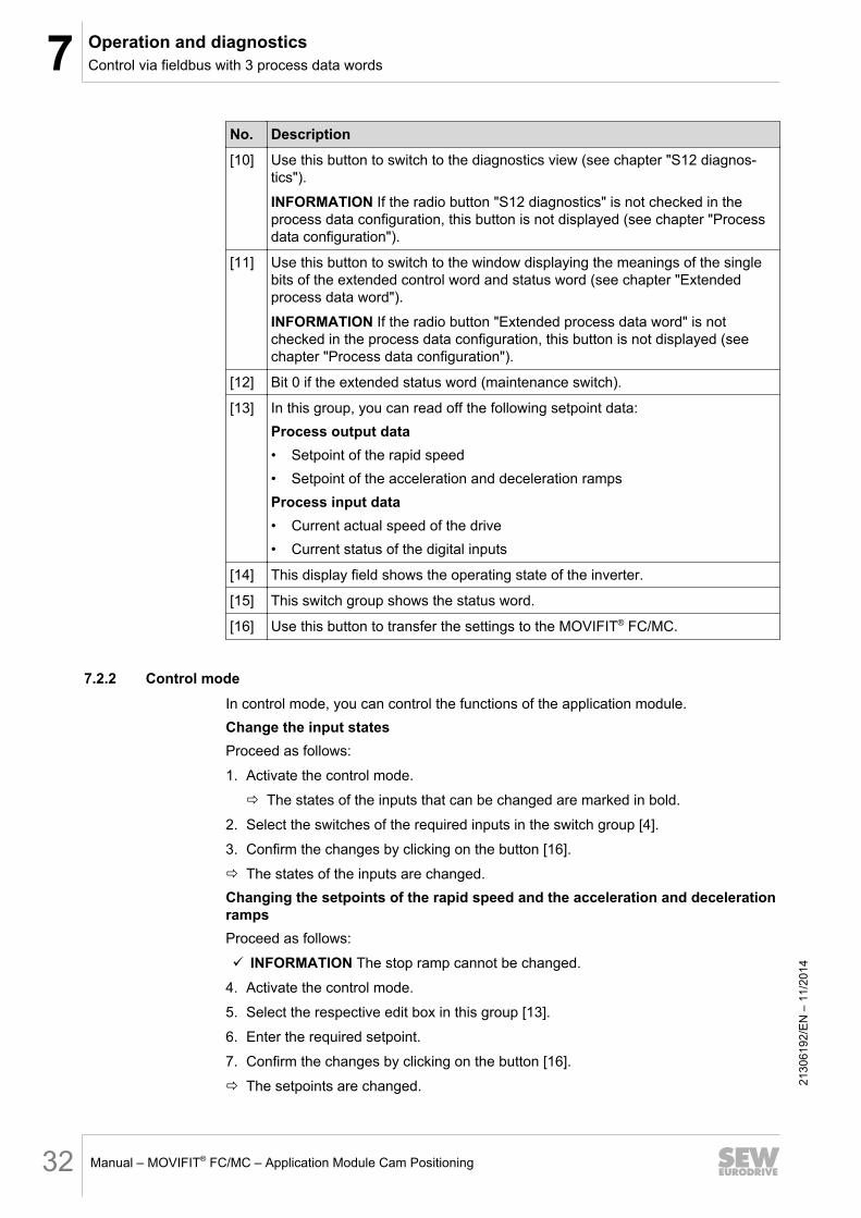
No. Description
[10] Use this button to switch to the diagnostics view (see chapter "S12 diagnos-tics").
INFORMATION If the radio button "S12 diagnostics" is not checked in the process data configuration, this button is not displayed (see chapter "Process data configuration").
[11] Use this button to switch to the window displaying the meanings of the single bits of the extended control word and status word (see chapter "Extended process data word").
INFORMATION If the radio button "Extended process data word" is not checked in the process data configuration, this button is not displayed (see chapter "Process data configuration").
[12] Bit 0 if the extended status word (maintenance switch).
[13] In this group, you can read off the following setpoint data:Process output data• Setpoint of the rapid speed• Setpoint of the acceleration and deceleration rampsProcess input data• Current actual speed of the drive• Current status of the digital inputs
[14] This display field shows the operating state of the inverter.
[15] This switch group shows the status word.
[16] Use this button to transfer the settings to the MOVIFIT® FC/MC.
7.2.2 Control modeIn control mode, you can control the functions of the application module.Change the input statesProceed as follows:
1. Activate the control mode.
ð The states of the inputs that can be changed are marked in bold.
2. Select the switches of the required inputs in the switch group [4].
3. Confirm the changes by clicking on the button [16].
ð The states of the inputs are changed.Changing the setpoints of the rapid speed and the acceleration and deceleration rampsProceed as follows:
ü INFORMATION The stop ramp cannot be changed.
4. Activate the control mode.
5. Select the respective edit box in this group [13].
6. Enter the required setpoint.
7. Confirm the changes by clicking on the button [16].
ð The setpoints are changed.
2130
6192
/EN
– 1
1/20
14
7Operation and diagnosticsControl via fieldbus with 6 process data words
Manual – MOVIFIT® FC/MC – Application Module Cam Positioning 33
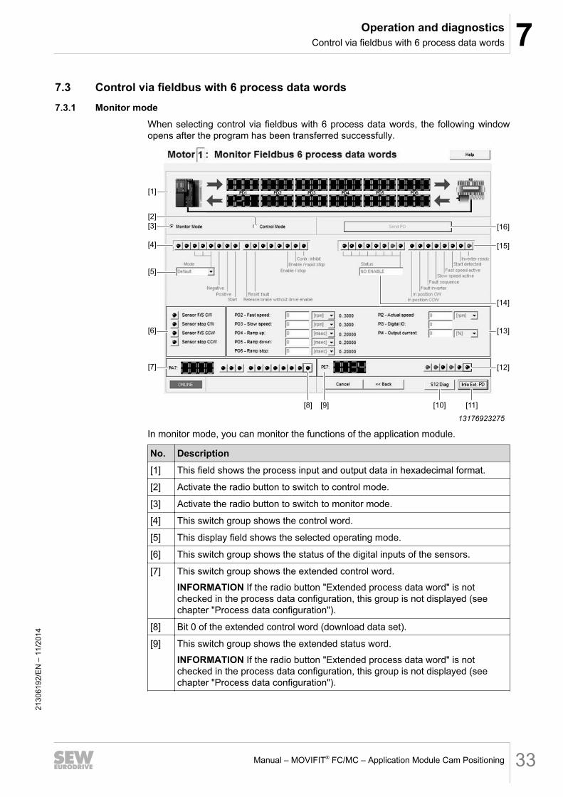
7.3 Control via fieldbus with 6 process data words7.3.1 Monitor mode
When selecting control via fieldbus with 6 process data words, the following window opens after the program has been transferred successfully.
[1]
[4]
[3]
[2]
[5]
[13]
[14]
[12]
[15]
[16]
[6]
[7]
[11][10][9][8]
13176923275
In monitor mode, you can monitor the functions of the application module.
No. Description
[1] This field shows the process input and output data in hexadecimal format.
[2] Activate the radio button to switch to control mode.
[3] Activate the radio button to switch to monitor mode.
[4] This switch group shows the control word.
[5] This display field shows the selected operating mode.
[6] This switch group shows the status of the digital inputs of the sensors.
[7] This switch group shows the extended control word.
INFORMATION If the radio button "Extended process data word" is not checked in the process data configuration, this group is not displayed (see chapter "Process data configuration").
[8] Bit 0 of the extended control word (download data set).
[9] This switch group shows the extended status word.
INFORMATION If the radio button "Extended process data word" is not checked in the process data configuration, this group is not displayed (see chapter "Process data configuration").
2130
6192
/EN
– 1
1/20
14

7 Operation and diagnosticsControl via fieldbus with 6 process data words
Manual – MOVIFIT® FC/MC – Application Module Cam Positioning34
No. Description
[10] Use this button to switch to the diagnostics view (see chapter "S12 diagnos-tics").
INFORMATION If the radio button "S12 diagnostics" is not checked in the process data configuration, this button is not displayed (see chapter "Process data configuration").
[11] Use this button to switch to the window displaying the meanings of the single bits of the extended control word and status word (see chapter "Extended process data word").
INFORMATION If the radio button "Extended process data word" is not checked in the process data configuration, this button is not displayed (see chapter "Process data configuration").
[12] Bit 0 if the extended status word (maintenance switch).
[13] In this group, you can read off the following setpoint data:Process output data• Setpoint of the rapid speed
• Creep speed setpoint
• Setpoint of all acceleration ramps• Setpoint of all deceleration ramps• Stop ramp setpointProcess input data• Current actual speed of the drive• Current status of the digital inputs• Current output current in relation to the maximum current
[14] This display field shows the operating state of the inverter.
[15] This switch group shows the status word.
[16] Use this button to transfer the settings to the MOVIFIT® FC/MC.
7.3.2 Control modeIn control mode, you can control the functions of the application module.Change the input statesProceed as follows:
1. Activate the control mode.
ð The states of the inputs that can be changed are marked in bold.
2. Select the switches of the required inputs in the switch group [4].
3. Confirm the changes by clicking on the button [16].
ð The states of the inputs are changed.Changing the setpoints of the rapid speed and the acceleration and deceleration rampsProceed as follows:
ü INFORMATION The stop ramp cannot be changed.
4. Activate the control mode.
21
3061
92/E
N –
11/
2014
7Operation and diagnosticsDiagnostics with the S12 safety option
Manual – MOVIFIT® FC/MC – Application Module Cam Positioning 35
5. Select the respective edit box in this group [13].
6. Enter the required setpoint.
7. Confirm the changes by clicking on the button [16].
ð The setpoints are changed.
7.4 Diagnostics with the S12 safety option7.4.1 Safety notes
The use of the S12 safety option with SLS1) is not permitted with dual-motor operation (SD30) as well as with the MOVIFIT® MC variants.In single-motor operation, S12 with SLS is always possible.S12 diagnostics is supported for the following MOVIFIT® units:
• MTx-P11A (PROFIBUS) → MOVIFIT® FC/MC• MTx-E21A (PROFINET) → MOVIFIT® FC/MC• MTx-E31A (EtherNet/IP™) → only MOVIFIT® FC
1) SLS = Safely limited speed
7.4.2 DescriptionS12 diagnostics provides status and diagnostics information of the S12 safety option on the "unsafe fieldbus part".If S12 diagnostics is activated, the process data (3PD) are automatically attached to the existing configuration.
7.4.3 S12 diagnostics viewOpen S12 diagnosticsProceed as follows:
1. Activate S12 diagnostics during the process data configuration (see chapter "Proc-ess data configuration").
2130
6192
/EN
– 1
1/20
14

7 Operation and diagnosticsDiagnostics with the S12 safety option
Manual – MOVIFIT® FC/MC – Application Module Cam Positioning36
2. Switch to monitor mode.
3. Click the button [S12 Diag] in monitor mode (see chapter "Monitor mode" of the se-lected control type).
ð The following window is displayed.
13179755915
You can read off the S12 diagnostics data in this window.
7.4.4 Structure of process dataThe following tables show the structure of the process data words.
Process data DesignationPI1 Safety functions
PI2 Safety status
PI3 Error number: 0x0000
Error number as entire data word 0: no error
21
3061
92/E
N –
11/
2014

7Operation and diagnosticsDiagnostics with the S12 safety option
Manual – MOVIFIT® FC/MC – Application Module Cam Positioning 37
Word Bit FunctionPI1 0 STO active
1 STO error
2 SS1(a) active
3 SS1(c) active
4 SLS0 active
5 SLS1 active
6 SLS2 active
7 SLS3 active
8 FDO-STO
9 FDO-0
10 FDO-1
11 Reserved
12 Reserved
13 Reserved
14 Reserved
15 Reserved
Word Bit FunctionPI2 0
S12 status:
0: Init
1: Parameterization
2: Verified
3: Start
4: RUN
5: STOP
1
2
3
4
5
6
7
8 FDI-0
9 FDI-1
10 FDI-2
11 FDI-3
12 FDI-4
13 FDI-5
14 FDI-6
15 FDI-7
2130
6192
/EN
– 1
1/20
14

7 Operation and diagnosticsExtended process data word
Manual – MOVIFIT® FC/MC – Application Module Cam Positioning38
7.5 Extended process data wordDuring process data configuration, you can configure an extended process data word.The extended process data word is set to the following position depending on the fol-lowing process data words that are selected:
• With 1 process data word: to the second position as second process data word.• With 3 process data words: to the fourth position as fourth process data word.• With 6 process data words: to the seventh position as seventh process data word.Configuring extended process data wordProceed as follows:
1. Activate the configuration of an extended process data word during the process data configuration (see chapter "Process data configuration").
2. Switch to monitor mode.
ð On the bottom of the monitor mode window, the following area is displayed.
[5]
[4][3][2][1]
13197243019
No. Description
[1] This switch group shows the extended control word.
[2] Bit 0 of the extended control word (download data set).
[3] This switch group shows the extended status word.
[4] Bit 0 if the extended status word (maintenance switch).
[5] Use this button to show or hide the meanings of the single bits of the extended control word and status word.
3. To show the meanings of the single bits of the extended control word and status word, click the button [4].
ð The following window opens.
13197655691
2130
6192
/EN
– 1
1/20
14

8Data managementSafety notes
Manual – MOVIFIT® FC/MC – Application Module Cam Positioning 39
8 Data management8.1 Safety notes
MOVIFIT® FC with the following fieldbus interfaces have a data management function:
• PROFIBUS
• PROFINET• DeviceNet™• EtherNet/IP™To enable data management, the application module must be installed on the EBOX1) .This has the following reasons:• Data management can only store the application and device parameters on the
ABOX2) , however, it cannot store the boot project there. The memory of the ABOX is too small for this.
INFORMATIONTo ensure correct execution of the data management function, the MOVIFIT® units must be operated in expert mode (see MOVIFIT® FC manual). To activate data man-agement and the control via fieldbus, an upload from the data management surface in MOVITOOLS® MotionStudio must be performed once.
1) Active electronics unit2) Passive connection unit
8.2 Activating data managementProceed as follows:
ü The application module is already installed on the EBOX.
1. Start MOVITOOLS® MotionStudio engineering software.
2. Open the data management surface.
2130
6192
/EN
– 1
1/20
14

8 Data managementActivating data management
Manual – MOVIFIT® FC/MC – Application Module Cam Positioning40
3. To switch to the upload function, click the button [1].
[1]
13176169483
ð The following window is displayed.
[2]
[1]
[3]
9007212430915339
No. Description[1] If the check box [Auto reload] is checked, the application and device parame-
ters are automatically reloaded after a unit replacement.
[2] If this check box is checked, the control of the data management via process data is enabled after successful upload.
INFORMATION This is only possible if the extended process data word is con-figured.
[3] Click this button to start the upload.
4. Activate the required functions.
5. Click the button [3] and perform an upload once.
2130
6192
/EN
– 1
1/20
14

8Data managementStructure of process data
Manual – MOVIFIT® FC/MC – Application Module Cam Positioning 41
8.3 Structure of process dataThe following tables show the structure of the process data words.
Process data Designation
PA Extended control word
PE Extended status word
Word Bit Function
PA 0 Download dataset
1 Upload dataset
2 Upload data set with auto reload
3 Reserved
4 Reserved
5 Reserved
6 Reboot system
7 Digital output DO00
8 Digital output DO01
9 Digital output DO02
10 Digital output DO03
11 – 15 Reserved
Word Bit Function
PE 0 Maintenance switch (mains OFF)
1 Toggle bit
2 Data management done
3 Data management busy
4 Dataset available
5 Auto reload configured
6
7
8
9
10
11 – 15
2130
6192
/EN
– 1
1/20
14

9 Terminal assignmentMOVIFIT FC "Technology" function level
Manual – MOVIFIT® FC/MC – Application Module Cam Positioning42
9 Terminal assignment9.1 MOVIFIT® FC with "Technology" function level
MOVIFIT FC "Technology" function level
The following table shows the digital inputs of the MOVIFIT® FC function level "Tech-nology".
Input Function
DI00 Sensor "F/S1) CW"
DI01 Sensor "Stop CW" (item control CCW)
DI02 Sensor "F/S1) CCW"
DI03 Sensor "Stop CCW" (item control CW)
DI04-DI15 Reserved1) F/S = Rapid/creep speed
9.2 MOVIFIT® MC with "Technology" function levelMOVIFIT MC with "Technology" function level
The following table shows the digital inputs of the MOVIFIT® MC function level "Tech-nology".
Input Function
DI00 Motor 1: Sensor "F/S1) CW"
DI01 Motor 1: Sensor "Stop CW" (item control CCW)
DI02 Motor 1: Sensor "F/S1) CCW"
DI03 Motor 1: Sensor "Stop CCW" (item control CW)
DI04 Motor 2: Sensor "F/S1) CW"
DI05 Motor 2: Sensor "Stop CW" (item control CCW)
DI06 Motor 2: Sensor "F/S1) CCW"
DI07 Motor 2: Sensor "Stop CCW" (item control CW)
DI08 Motor 3: Sensor "F/S1) CW"
DI09 Motor 3: Sensor "Stop CW" (item control CCW)
DI10 Motor 3: Sensor "F/S1) CCW"
DI11 Motor 3: Sensor "Stop CCW" (item control CW)1) F/S = Rapid/creep speed
2130
6192
/EN
– 1
1/20
14

10Process dataProcess data interface with the PLC with 1 process data word
Manual – MOVIFIT® FC/MC – Application Module Cam Positioning 43
10 Process data10.1 Process data interface with the PLC with 1 process data word10.1.1 Overview
The following table shows an overview of the process data words for control via field-bus with 1 process data word.
Process data Designation
PO1 Control word
PI1 Status word
10.1.2 Process output dataThe following table shows the process output data from the PLC to the MOVIFIT®
FC/MC for control via fieldbus with 1 process data word.
Word Bit Function
PO1 0 1 = Controller in-hibit
0 = Enable
1 1 = Enable 0 = Rapid stop
2 1 = Enable 0 = Stop
3 Reserved
4 Reserved
5 Reserved
6 Error malfunction
7 Reserved
8 Start
9 Positive (CW rotation)
10 Negative (CCW rotation)
11 Mode 20 000 = operating mode 0: Reserved
001 = operating mode 1: Jog mode
010 = operating mode 2: Feed-in
011 = operating mode 3: Feed-out
100 = operating mode 4: Lifting/rotating
12 Mode 21
13 Mode 22
14 Reserved
15 Reserved
10.1.3 Process input dataThe following table shows the process input data from the MOVIFIT® FC/MC to the PLC for control via fieldbus with 1 process data word.
Word Bit Function
PI1 0 Ready for operation
1 Start detected
2130
6192
/EN
– 1
1/20
14

10 Process dataProcess data interface with the PLC with 3 process data words
Manual – MOVIFIT® FC/MC – Application Module Cam Positioning44
Word Bit Function
2 Rapid speed active
3 Creep speed active
4 Sequence fault
5 Inverter fault
6 In position CW (top)
7 In position CCW (bottom)
8-15 Inverter/error state
10.2 Process data interface with the PLC with 3 process data words10.2.1 Overview
The following table shows an overview of the process data words for control via field-bus with 3 process data words.
Process data Designation
PO1 Control word
PO2 Rapid speed [rpm]
PO3 Ramp [ms]
PI1 Status word
PI2 Actual speed [rpm]
PI3 Digital inputs
2130
6192
/EN
– 1
1/20
14

10Process dataProcess data interface with the PLC with 3 process data words
Manual – MOVIFIT® FC/MC – Application Module Cam Positioning 45
10.2.2 Process output dataThe following table shows the process output data from the PLC to the MOVIFIT®
FC/MC for control via fieldbus with 3 process data words.
Word Bit Function
PO1 0 1 = Controller in-hibit
0 = Enable
1 1 = Enable 0 = Rapid stop
2 1 = Enable 0 = Stop
3 Reserved
4 Reserved
5 Reserved
6 Reset fault
7 Reserved
8 Start
9 Positive (CW rotation)
10 Negative (CCW rotation)
11 Mode 20 000 = operating mode 0: Reserved
001 = operating mode 1: Jog mode
010 = operating mode 2: Feed-in
011 = operating mode 3: Feed-out
100 = operating mode 4: Lifting/rotating
12 Mode 21
13 Mode 22
14 Reserved
15 Reserved
PO2 0-15 Rapid speed [rpm]
PO3 15 Acceleration and deceleration ramp [ms]
2130
6192
/EN
– 1
1/20
14

10 Process dataProcess data interface with the PLC with 6 process data words
Manual – MOVIFIT® FC/MC – Application Module Cam Positioning46
10.2.3 Process input dataThe following table shows the process input data from the MOVIFIT® FC/MC to the PLC for control via fieldbus with 3 process data words.
Word Bit Function
MOVIFIT® FCFunction level"Technology"
MOVIFIT® MCFunction level"Technology"
PI1 00 Ready for operation
01 Start detected
02 Rapid speed active
03 Creep speed active
04 Sequence fault
05 Inverter fault
06 In position CW (top)
07 In position CCW (bottom)
8-15 Inverter/error state
PI2 0-15 Actual speed [rpm] No function
PI3 0 Sensor "F/S1) CW"
1 Sensor "stop CW"
2 Sensor "F/S1) CCW"
3 Sensor "stop CCW"
4-11 DI04 – DI11
12-15 DI12 – DI151) F/S = Rapid/creep speed
10.3 Process data interface with the PLC with 6 process data words10.3.1 Overview
The following table shows an overview of the process data words for control via field-bus with 6 process data words.
Process data Designation
PO1 Control word
PO2 Rapid speed [rpm]
PO3 Creep speed [rpm]
PO4 Ramp up [ms]
PO5 Ramp down [ms]
PO6 Stop ramp [ms]
PI1 Status word
PI2 Actual speed [rpm]
2130
6192
/EN
– 1
1/20
14
10Process dataProcess data interface with the PLC with 6 process data words
Manual – MOVIFIT® FC/MC – Application Module Cam Positioning 47
Process data Designation
PI3 Digital inputs
PI4 Output current [%]
PI5 Reserved
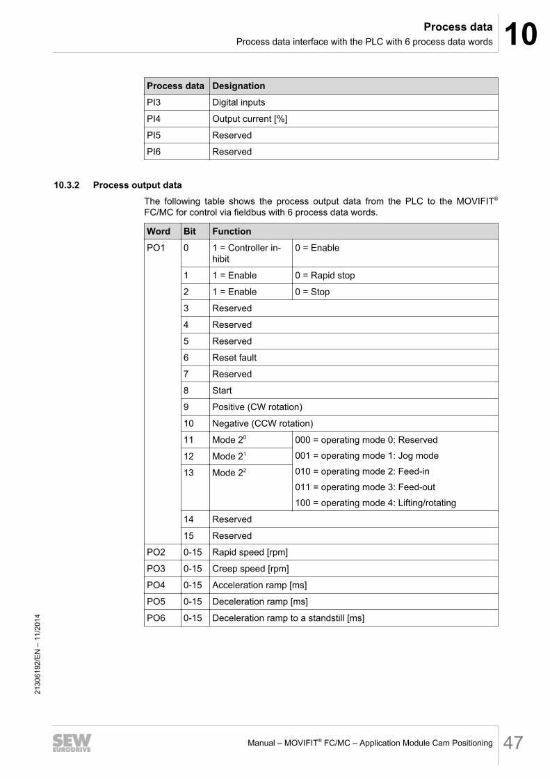
PI6 Reserved
10.3.2 Process output dataThe following table shows the process output data from the PLC to the MOVIFIT®
FC/MC for control via fieldbus with 6 process data words.
Word Bit Function
PO1 0 1 = Controller in-hibit
0 = Enable
1 1 = Enable 0 = Rapid stop
2 1 = Enable 0 = Stop
3 Reserved
4 Reserved
5 Reserved
6 Reset fault
7 Reserved
8 Start
9 Positive (CW rotation)
10 Negative (CCW rotation)
11 Mode 20 000 = operating mode 0: Reserved
001 = operating mode 1: Jog mode
010 = operating mode 2: Feed-in
011 = operating mode 3: Feed-out
100 = operating mode 4: Lifting/rotating
12 Mode 21
13 Mode 22
14 Reserved
15 Reserved
PO2 0-15 Rapid speed [rpm]
PO3 0-15 Creep speed [rpm]
PO4 0-15 Acceleration ramp [ms]
PO5 0-15 Deceleration ramp [ms]
PO6 0-15 Deceleration ramp to a standstill [ms]
2130
6192
/EN
– 1
1/20
14

10 Process dataProcess data interface with the PLC with 6 process data words
Manual – MOVIFIT® FC/MC – Application Module Cam Positioning48
10.3.3 Process input dataThe following table describes the process input data from the MOVIFIT® FC/MC to the PLC for control via fieldbus with 6 process data words.
Word Bit Function
MOVIFIT® FCFunction level"Technology"
MOVIFIT® MCFunction level"Technology"
PI1 00 Ready for operation
01 Start detected
02 Rapid speed active
03 Creep speed active
04 Sequence fault
05 Inverter fault
06 In position CW (top)
07 In position CCW (bottom)
8-15 Inverter/error state
PI2 0-15 Actual speed [rpm] No function
PI3 0 Sensor "F/S1) CW"
1 Sensor "stop CW"
2 Sensor "F/S1) CCW"
3 Sensor "stop CCW"
4-11 DI04 – DI11
12-15 DI12 – DI15
PI4 0-15 Output current [%] No function
PI5-6 0-15 Reserved1) F/S = Rapid/creep speed
2130
6192
/EN
– 1
1/20
14

Index
IndexB
Bus system............................................................. 9
C
Configuring the monitoring functions.................... 25Control
via fieldbus 1 PD ............................................. 29via fieldbus 3 PD ............................................. 31via fieldbus 6 PD ............................................. 33
Control modeControl via fieldbus 1 PD ................................ 30Control via fieldbus 3 PD .......................... 32, 34Control via fieldbus 6 PD .......................... 32, 34
Copyright................................................................ 7Cycle diagram
Feed-in/feed-out.............................................. 18Jog mode ........................................................ 20Lifting/rotating ................................................. 19
D
Data managementDescription ...................................................... 39Structure of process data................................ 41
Description ........................................................... 10Diagnostics with the S12 safety option
Structure of process data................................ 36Download ............................................................. 28
E
Embedded safety notes ......................................... 6Exclusion of liability ................................................ 6
F
Feed-in ..................................................... 11, 12, 15Feed-out......................................................... 11, 13
H
Hazard symbolsMeaning ............................................................ 5
I
InputsChange state....................................... 30, 32, 34
Inputs/outputsMOVIFIT® FC .................................................. 42
MOVIFIT® MC ................................................. 42
J
Jog mode ............................................................. 16
L
Liability ................................................................... 6Liability for defects ................................................. 6Lifting.................................................................... 14
M
Max. time intervalStart signal → Sensor "item control" ............... 25Start signal → Sensor "rapid/creep speed"..... 25Start signal → Sensor "stop"........................... 26
Monitor modeControl via fieldbus 1 PD ................................ 29Control via fieldbus 3 PD ................................ 31Control via fieldbus 6 PD ................................ 33
MOVITOOLS® MotionStudioInstallation....................................................... 21
N
NotesDesignation in the documentation..................... 5Meaning of the hazard symbols ........................ 5
O
Operating modeDescription ...................................................... 11Feed-in...................................................... 12, 15Feed-out.......................................................... 13Jog mode ........................................................ 16Lifting/rotating ................................................. 14Setting....................................................... 32, 34
P
Process data configuration................................... 24Process data interface with the PLC
1 process data word........................................ 433 process data words...................................... 446 process data words...................................... 46
Product names....................................................... 7Properties............................................................. 10
2130
6192
/EN
– 1
1/14
Manual – MOVIFIT® FC/MC – Application Module Cam Positioning 49

Index
R
Rapid/creep speed positioning............................. 11Roller conveyor .................................................... 11
S
S12 diagnosticsSafety notes .................................................... 35Use.................................................................. 35
Safety notes ........................................................... 8Data management .......................................... 39Designation in the documentation..................... 5General ............................................................. 8Meaning of the hazard symbols ........................ 5S12 diagnostics............................................... 35Structure of embedded ..................................... 6Structure of section-related............................... 5
Section-related safety notes................................... 5Select control ....................................................... 24Setpoints .............................................................. 26Signal words in the safety notes ............................ 5Starting the application module............................ 21Startup
Preparation ..................................................... 21
T
Target group........................................................... 8Trademarks ............................................................ 7Transfer program ................................................. 28Turning ................................................................. 14
W
WindowDownload ........................................................ 28Monitor fieldbus 1 process data word ............. 29Monitor fieldbus 3 process data words ........... 31Monitor fieldbus 6 process data words ........... 33Monitoring functions........................................ 25Process data configuration ............................. 24Setpoints ......................................................... 26Start ................................................................ 21Startup ............................................................ 23
2130
6192
/EN
– 1
1/14
Manual – MOVIFIT® FC/MC – Application Module Cam Positioning50


SEW-EURODRIVE—Driving the world
SEW-EURODRIVE GmbH & Co KGP.O. Box 302376642 BRUCHSALGERMANYPhone +49 7251 75-0Fax +49 [email protected]
www.sew-eurodrive.com