Manual Model 1268 - Curtis Instruments, Inc. · 2 Curtis 1268 Manual, Rev. D Like all Curtis motor...
66
Manual Model 1268 Electronic Motor Controller Read Instructions Carefully! Specifications are subject to change without notice. © 2012 Curtis Instruments, Inc. ® Curtis is a registered trademark of Curtis Instruments, Inc. © The design and appearance of the products depicted herein are the copyright of Curtis Instruments, Inc. 37873 Rev D 3/12 Curtis Instruments, Inc. 200 Kisco Avenue Mt. Kisco, NY 10549 www.curtisinstruments.com
Transcript of Manual Model 1268 - Curtis Instruments, Inc. · 2 Curtis 1268 Manual, Rev. D Like all Curtis motor...

Manual
Model 1268Electronic Motor Controller
Read Instructions Carefully!
Specifications are subject to change without notice.© 2012 Curtis Instruments, Inc. ® Curtis is a registered trademark of Curtis Instruments, Inc.© The design and appearance of the products depicted herein are the copyright of Curtis Instruments, Inc. 37873 Rev D 3/12
Curtis Instruments, Inc.200 Kisco Avenue
Mt. Kisco, NY 10549www.curtisinstruments.com


Curtis 1268 Manual, Rev. D iii
CONTENTS
1. OVERVIEW ..............................................................................1
2. INSTALLATION AND WIRING .............................................4 Mounting the Controller .....................................................4 Connections: Low Current ..................................................6 Connections: High Current ................................................7 Wiring: Controller ..............................................................8 Wiring: Throttle ................................................................10 Wiring: Drivers .................................................................12 Wiring: External LED Output ..........................................13 Wiring: Pedal Interlock Switch ..........................................13 Contactor, Switches, and Other Hardware .........................14
3. PROGRAMMABLE PARAMETERS ......................................15 Acceleration/Deceleration Parameters .................................17 Acceleration Rate: M1, M2, Reverse Deceleration Rate: M1, M2, Reverse Field Brake Field Brake Speed Field Brake Max Field Brake Rate
Speed Parameters ...............................................................19 Max Forward Speed: M1, M2 Max Reverse Speed RPM To Speed Tacho Poles
Throttle Parameters ............................................................20 Throttle 0% Throttle 100% Throttle Map Throttle Fault Low Throttle Fault High
Current Limit Parameters ...................................................21 Main Current Limit: M1, M2 Regen Current Limit Plug Braking Current Limit WalkAway™ Current Limit
Brake Mapping Parameters ................................................22 Brake Minimum: M1, M2, Reverse Brake Maximum: M1, M2, Reverse Brake Start: M1, M2, Reverse Brake End: M1, M2, Reverse Brake Map: M1, M2, Reverse
Field Mapping Parameters ..................................................24 Forward Field Minimum: M1, M2 Reverse Field Minimum
CONTENTS

iv Curtis 1268 Manual, Rev. D
Field Max Negative Field Maximum Field Map Start / Negative Field Map Start Field Map End / Negative Field Map End Field Ramp / Negative Field Ramp Field Direction Swap
Fault Parameters .................................................................26 KSI SRO Enable Mode After KSI Overvoltage Low Voltage Warning Option
Output Driver Parameters ..................................................28 Auxiliary Driver Mode Auxiliary Pull-In Voltage Auxiliary Holding Voltage Electromagnetic Brake Delay Electromagnetic Brake Speed Check Electromagnetic Brake at Speed Value Driver Overcurrent Detection
4. INSTALLATION CHECKOUT .............................................31
5. TUNING GUIDE ..................................................................33 Major Tuning .....................................................................33 1 Tuning the active throttle range ..............................33 2 Calibrating the controller speed measurement ........35 3 Tuning the controller to the motor ........................35 4 Equalizing loaded and unloaded vehicle speed .......38 5 Confirming loaded vehicle speed on downhill ........39 Fine Tuning ........................................................................40 6 Response to increased throttle ................................40 7 Response to full throttle release ..............................41 8 Transitioning from flat ground to downhill ............43 9 Hill climbing ..........................................................43 bk WalkAway™ braking ...............................................44 bl Low-speed field braking .........................................44 bm EM brake operation ...............................................45
6. DIAGNOSTICS AND TROUBLESHOOTING ....................47
7. MAINTENANCE ...................................................................50
APPENDIX A Vehicle Design Considerations
APPENDIX B Programming Devices & Menus
APPENDIX C Programmable Parameter Index
APPENDIX D Specifications, 1268 Controller
CONTENTS
Curtis 1268 Manual, Rev. D v
FIGURES
fig. 1: Curtis 1268 electronic motor controller .............................. 1
fig. 2: Mounting dimensions, Curtis 1268 controller ................... 4
fig. 3a: Standard wiring configuration — with aux driver used for an EM brake ................................. 8
fig. 3b: Standard wiring configuration — with aux driver used for a WalkAway™ relay ....................... 9
fig. 4: Wiring for 3-wire potentiometer throttle ......................... 10
fig. 5: Wiring for 0–5V throttle ................................................. 10
fig. 6: Wiring for ITS throttle .................................................... 11
fig. 7: Throttle map structure .................................................... 20
fig. 8: Brake map structure ......................................................... 23
fig. 9: Field map structure .......................................................... 25
FIGURES


Curtis 1268 Manual, Rev. D 1
OVERVIEW
Curtis 1268 controllers are separately excited motor speed controllers designed for use in a variety of transport vehicles. These programmable controllers are simple to install, efficient, and cost effective. Typical applications include heavy-duty golf carts, personnel transports, burden carriers, and other utility vehicles.
The 1268 controller offers smooth, silent, cost effective control of motor speed and torque. The speed sensor input allows superior closed-loop control for regulating vehicle speed. Unique braking parameters allow simple, intuitive deceleration tuning. A full-bridge field winding control stage is combined with a half-bridge armature power stage to provide solid state motor reversing and regenerative braking power without additional relays or contactors.
Fig. 1 Curtis 1268 electronic motor controller.
These controllers are fully programmable by means of the optional hand-held programmer or PC programming station. Use of a programmer provides diagnostic and test capability as well as configuration flexibility and the ability to easily transfer settings from one controller to another.
1 — OVERVIEW
1
2 Curtis 1268 Manual, Rev. D
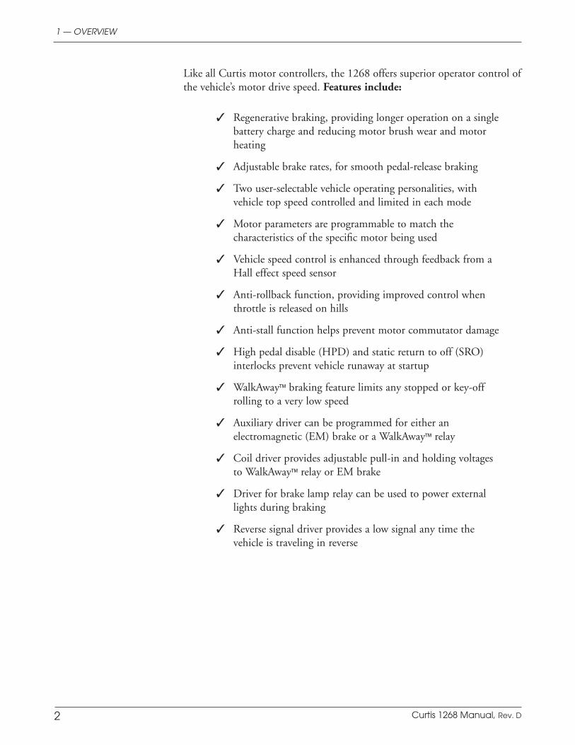
Like all Curtis motor controllers, the 1268 offers superior operator control of the vehicle’s motor drive speed. Features include:
✓ Regenerative braking, providing longer operation on a single battery charge and reducing motor brush wear and motor heating
✓ Adjustable brake rates, for smooth pedal-release braking
✓ Two user-selectable vehicle operating personalities, with vehicle top speed controlled and limited in each mode
✓ Motor parameters are programmable to match the characteristics of the specific motor being used
✓ Vehicle speed control is enhanced through feedback from a Hall effect speed sensor
✓ Anti-rollback function, providing improved control when throttle is released on hills
✓ Anti-stall function helps prevent motor commutator damage
✓ High pedal disable (HPD) and static return to off (SRO) interlocks prevent vehicle runaway at startup
✓ WalkAway™ braking feature limits any stopped or key-off rolling to a very low speed
✓ Auxiliary driver can be programmed for either an electromagnetic (EM) brake or a WalkAway™ relay
✓ Coil driver provides adjustable pull-in and holding voltages to WalkAway™ relay or EM brake
✓ Driver for brake lamp relay can be used to power external lights during braking
✓ Reverse signal driver provides a low signal any time the vehicle is traveling in reverse
1 — OVERVIEW
Curtis 1268 Manual, Rev. D 3
✓ Driver outputs are short circuit protected and provide built-in coil spike protection
✓ Warning buzzer sounds steady in reverse, intermittent during WalkAway™ braking
✓ Complete diagnostics through any of the optional programmers and through the built-in Status LED
✓ Driver for remote Status LED enables status information to be available at a dashboard
✓ Sealed package is rated at IP64 and IP67
✓ Meets or exceeds EEC fault detect requirements.
Familiarity with your Curtis controller will help you install and operate it properly. We encourage you to read this manual carefully. If you have ques-tions, please contact the Curtis office nearest you.
1 — OVERVIEW

4 Curtis 1268 Manual, Rev. D
INSTALLATION AND WIRING
MOUNTING THE CONTROLLER
The outline and mounting hole dimensions for the 1268 controller are shown in Figure 2.
The controller can be oriented in any position, and meets the IP64/IP67 ratings for environmental protection against dust and water. However, the lo-cation should be carefully chosen to keep the controller as clean and dry as possible. When selecting the mounting position, be sure to also take into consideration (1) that access is needed at the top of the controller to plug the programmer into its connector, and (2) that the built-in Status LED is visible only through the view port in the label on top of the controller.
Fig. 2 Mounting dimensions, Curtis 1268 controller.
Dimensions in millimeters (and inches)
2 — INSTALLATION & WIRING: Controller
2
9.5(0.375)
12.7(0.50)
STATUSLED
M8 thread, 3 plcs
M6 thread, 2 plcs
7.1 (0.28) dia.,4 plcs
159(6.25)
178(7.00)
81(3.19)
210 (8.25)
229 (9.00)

Curtis 1268 Manual, Rev. D 5
To ensure full rated power, the controller should be fastened to a clean, flat metal surface with four M6 (1/4") diameter screws, using the holes provided. Although not required, a thermal joint compound can be used to improve heat conduction from the controller heatsink to the mounting surface.
You will need to take steps during the design and development of your end product to ensure that its EMC performance complies with applicable regulations; suggestions are presented in Appendix A.
The 1268 controller contains ESD-sensitive components. Use appropri-ate precautions in connecting, disconnecting, and handling the controller. See installation suggestions in Appendix A for protecting the controller from ESD damage.
Working on electric vehicles is potentially dangerous. You should protect yourself against runaways, high current arcs, and outgassing from lead acid batteries:
RUNAWAYS — Some conditions could cause the vehicle to run out of control. Disconnect the motor or jack up the vehicle and get the drive wheels off the ground before attempting any work on the motor control circuitry.
HIGH CURRENT ARCS — Electric vehicle batteries can supply very high power, and arcs can occur if they are short circuited. Always open the battery circuit before working on the motor control circuit. Wear safety glasses, and use properly insulated tools to prevent shorts.
LEAD ACID BATTERIES — Charging or discharging generates hydrogen gas, which can build up in and around the batteries. Follow the battery manufacturer’s safety recommendations. Wear safety glasses.
2 — INSTALLATION & WIRING: Controller
☞C A U T I O N

6 Curtis 1268 Manual, Rev. D
CONNECTIONS
Low Current Connections
Three low current connectors are built into the 1268 controller. They are located in a row on the top of the controller:
J1-1 Keyswitch Input (KSI) input and return for main contactor coil J1-2 Logic Enable input from run/store switchJ1-3 Fuse Sense input from WalkAway™ fuse sense lineJ1-4 Logic Power power to controller logicJ1-5 (not used) —J1-6 (not used) —J1-7 (not used) —J1-8 Pedal Interlock Switch input from pedal switch, wired to throttleJ1-9 WalkAway™ Return coil return for WalkAway™ relay J1-10 Forward input from forward switchJ1-11 Reverse input from reverse switchJ1-12 (not used) — J1-13 Pot High +5V supply through 453Ω (or ITS input)J1-14 Pot Low 453Ω to groundJ1-15 Pot Wiper throttle wiper input (or ITS input) J1-16 LED Ground ground for external LEDJ1-17 Main Contactor contactor coil driver low-side outputJ1-18 Brake Light Driver relay driver low-side outputJ1-19 Reverse Alarm alarm low-side driver output J1-20 Mode Switch input from mode switchJ1-21 (not used) —J1-22 External LED Driver LED driver high-side outputJ1-23 Auxiliary Driver WalkAway™/EMB driver low-side output J1-24 (not used) —
The 24-pin connector provides the logic control connections. The mat-ing connector is a 24-pin Molex Mini-Fit Jr. connector p/n 39-01-2245 using type 5556 terminals. The appropriate wire gauge is 18–24 AWG.
2 — INSTALLATION & WIRING: Controller
J1 J2 J3
J1 Logic connectorJ2 Speed Sensor connectorJ3 Programmer connector
24 23 22 21 20 19 18 17 16 15 14 13
12 11 10 9 8 7 6 5 4 3 2 1
J1

Curtis 1268 Manual, Rev. D 7
F1
B- B+M-
F2
STATUSLED
CABLE-FREE ZONE
A 6-pin low power Molex connector is provided for the interface with the Hall speed sensor. The mating connector is a Molex Mini-Fit Jr. p/n 39-01-2065 using type 5556 terminals.
J2-1,2,3 (not used)
J2-4 groundJ2-5 inputJ2-6 +15V
Power cables must not be routed over the indicated area. Otherwise they may interfere with the proper operation of sensitive electromagnetic compo-nents located underneath.
The +15V supply should only be used with the speed sensor and not to power any other external systems.
A 4-pin low power connector is provided for an optional programmer. A com-plete handheld programmer kit, including the appropriate connecting cable with mating connector, can be ordered from Curtis: p/n 168961101 for the User Programmer (model 1311-1101) p/n 168962101 for the OEM Programmer (model 1311-4401).If a handheld programmer is already available (such as the now discontinued 1307) but has an incompatible cable, the appropriate connecting cable can be ordered as a separate part: p/n 16185.
If a 1314 PC programming station is used, the 1309 interface box and cable connect the computer to the controller: p/n 117465704 1314-1101, 1314 PC Programming Station (User) CD-ROM p/n 117465707 1314-4401, 1314 PC Programming Station (OEM) CD-ROM p/n 16994001 1309 Interface Box p/n 16185 Molex cable for 1309 Interface Box.
High Current Connections
Five tin-plated solid aluminum bus bars are provided for the high current con-nections to the battery (B+ and B-), the motor armature (M-), and the motor field (F1 and F2). These bus bars incorporate threaded mounting studs designed to accept mounting bolts. This simplifies the assembly and reduces the mount-ing hardware necessary for the power connections.
SIZE MAX DEPTH QTY MAX TORQUE
Field studs M6 × 1 5/8" 2 16.3 N·m (12 ft-lbs)
Power studs M8 × 1.25 3/4" 3 20.0 N·m (15 ft-lbs)
Exceeding these specifications could damage the bus bars’ internal threads, resulting in loose connections. We recommend maximum possible thread engagement: always exceeding three threads.
2 — INSTALLATION & WIRING: Controller
456
123
34
12
J3
J2
J3-1 Rx DataJ3-2 B-J3-3 Tx DataJ3-4 +15V
☞C A U T I O N
note: The 1311 hand-held programmer has been superseded; if you are using a more recent model, please refer to its documentation.

8 Curtis 1268 Manual, Rev. D
WIRING: Standard Configuration
Figures 3a and 3b show typical wiring. The system can include an electromag-netic brake or a WalkAway™ relay, but not both. Figure 3a shows a system with an EM brake; Figure 3b shows a system with a WalkAway™ relay.
Standard Power Wiring
Motor armature winding is straightforward, with the armature’s A1 connection going to the controller’s B+ bus bar and the armature’s A2 connection going to the controller’s M- bus bar.
The motor’s field connections (F1 and F2) to the controller are less obvious. The direction of vehicle travel with the forward direction selected will depend on how the F1 and F2 connections are made to the controller’s two field terminals and how the motor shaft is connected to the drive wheels through the vehicle’s drive train.
Fig. 3a Standard wiring configuration for Curtis 1268 controller, in an application with an EM brake.
2 — INSTALLATION & WIRING: Controller
1268 CONTROLLER
PEDAL INTERLOCK
BRAKE LIGHT RELAY
J1-20MODE (M1, M2)
J1-18
REVERSE ALARM J1-19
EM BRAKE J1-23
POT HIGHJ1-13
POT WIPERJ1-15
POT LOWJ1-14
THRO
TTLE
PO
T
A
MAIN
REVERSE
FORWARD
J1-1 KSI
SPEEDSENSOR
J2-4J2-5J2-6
BATTERY
RUN/STORE
SWITCH(10 A)
B+
GROUND
+15V
M-
INPUT
B-
A1
A2
J3-1J3-2J3-3
PRO
GRA
MM
ER RX DATA
TX DATAB-
J3-4+15V
F1
F2
F1
F2
KEYSWITCHJ1-10F
R
NJ1-11
J1-17 MAIN CONTACTOR
J1-16
J1-22LED DRIVER
+ -
J1-2
J1-4
LOGIC ENABLE
LOGIC POWER
CHARGER INTERLOCKSWITCH(optional)
J1-8
GROUND
Curtis 1268 Manual, Rev. D 9
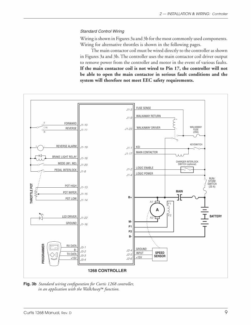
Standard Control Wiring
Wiring is shown in Figures 3a and 3b for the most commonly used components. Wiring for alternative throttles is shown in the following pages.
The main contactor coil must be wired directly to the controller as shown in Figures 3a and 3b. The controller uses the main contactor coil driver output to remove power from the controller and motor in the event of various faults. If the main contactor coil is not wired to Pin 17, the controller will not be able to open the main contactor in serious fault conditions and the system will therefore not meet EEC safety requirements.
2 — INSTALLATION & WIRING: Controller
Fig. 3b Standard wiring configuration for Curtis 1268 controller, in an application with the WalkAway™ function.
1268 CONTROLLER
PEDAL INTERLOCK
BRAKE LIGHT RELAY
J1-20MODE (M1, M2)
J1-18
REVERSE ALARM J1-19
POT HIGH J1-13
POT WIPER J1-15
POT LOW J1-14
THRO
TTLE
PO
T
A
MAIN
REVERSE
FORWARD
J1-1 KSI
SPEEDSENSOR
J2-4J2-5J2-6
BATTERY
RUN/STORE
SWITCH(20 A)
B+
GROUND
+15V
M-
INPUT
B-
A1
A2
J3-1J3-2J3-3
PRO
GRA
MM
ER RX DATA
TX DATAB-
J3-4+15V
F1
F2
F1
F2
KEYSWITCH
J1-10F
R
NJ1-11
J1-17 MAIN CONTACTOR
J1-16
J1-22LED DRIVER
GROUND
+ -
J1-2
J1-4
LOGIC ENABLE
LOGIC POWER
CHARGER INTERLOCKSWITCH (optional)
J1-8
J1-3
-
+
FUSE SENSE
J1-9
J1-23WALKAWAY
FUSE(20A)
WALKAWAY DRIVER
WALKAWAY RETURN
10 Curtis 1268 Manual, Rev. D
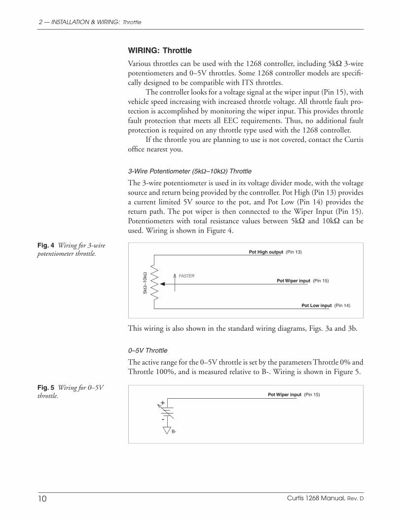
WIRING: Throttle
Various throttles can be used with the 1268 controller, including 5kΩ 3-wire potentiometers and 0–5V throttles. Some 1268 controller models are specifi-cally designed to be compatible with ITS throttles.
The controller looks for a voltage signal at the wiper input (Pin 15), with vehicle speed increasing with increased throttle voltage. All throttle fault pro-tection is accomplished by monitoring the wiper input. This provides throttle fault protection that meets all EEC requirements. Thus, no additional fault protection is required on any throttle type used with the 1268 controller.
If the throttle you are planning to use is not covered, contact the Curtis office nearest you.
3-Wire Potentiometer (5kΩ–10kΩ) Throttle
The 3-wire potentiometer is used in its voltage divider mode, with the voltage source and return being provided by the controller. Pot High (Pin 13) provides a current limited 5V source to the pot, and Pot Low (Pin 14) provides the return path. The pot wiper is then connected to the Wiper Input (Pin 15). Potentiometers with total resistance values between 5kΩ and 10kΩ can be used. Wiring is shown in Figure 4.
2 — INSTALLATION & WIRING: Throttle
Fig. 4 Wiring for 3-wire potentiometer throttle.
This wiring is also shown in the standard wiring diagrams, Figs. 3a and 3b.
0–5V Throttle
The active range for the 0–5V throttle is set by the parameters Throttle 0% and Throttle 100%, and is measured relative to B-. Wiring is shown in Figure 5.
Fig. 5 Wiring for 0–5V throttle. +
-
Curtis 1268 Manual, Rev. D 11
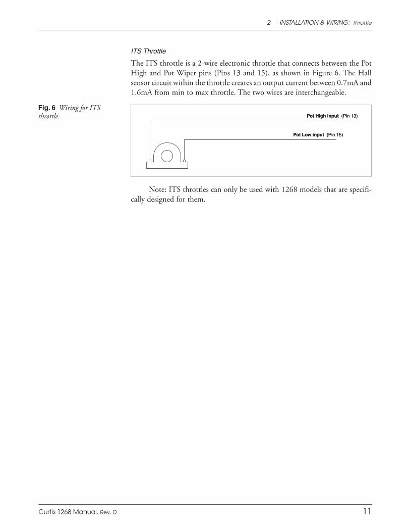
ITS Throttle
The ITS throttle is a 2-wire electronic throttle that connects between the Pot High and Pot Wiper pins (Pins 13 and 15), as shown in Figure 6. The Hall sensor circuit within the throttle creates an output current between 0.7mA and 1.6mA from min to max throttle. The two wires are interchangeable.
2 — INSTALLATION & WIRING: Throttle
Note: ITS throttles can only be used with 1268 models that are specifi-cally designed for them.
Fig. 6 Wiring for ITSthrottle. Pot High input (Pin 13)
Pot Low input (Pin 15)
12 Curtis 1268 Manual, Rev. D
2 — INSTALLATION & WIRING: Throttle
WIRING: Drivers
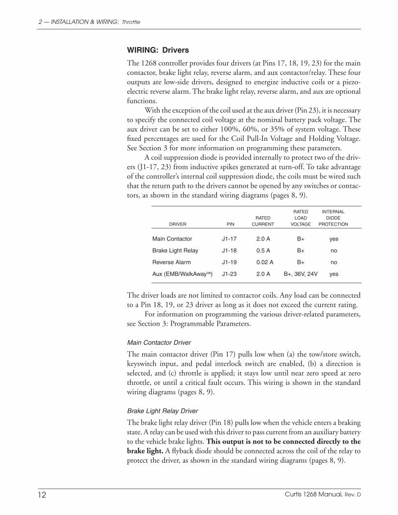
The 1268 controller provides four drivers (at Pins 17, 18, 19, 23) for the main contactor, brake light relay, reverse alarm, and aux contactor/relay. These four outputs are low-side drivers, designed to energize inductive coils or a piezo-electric reverse alarm. The brake light relay, reverse alarm, and aux are optional functions.
With the exception of the coil used at the aux driver (Pin 23), it is necessary to specify the connected coil voltage at the nominal battery pack voltage. The aux driver can be set to either 100%, 60%, or 35% of system voltage. These fixed percentages are used for the Coil Pull-In Voltage and Holding Voltage. See Section 3 for more information on programming these parameters.
A coil suppression diode is provided internally to protect two of the driv-ers (J1-17, 23) from inductive spikes generated at turn-off. To take advantage of the controller’s internal coil suppression diode, the coils must be wired such that the return path to the drivers cannot be opened by any switches or contac-tors, as shown in the standard wiring diagrams (pages 8, 9).
RATED INTERNAL RATED LOAD DIODE DRIVER PIN CURRENT VOLTAGE PROTECTION
Main Contactor J1-17 2.0 A B+ yes
Brake Light Relay J1-18 0.5 A B+ no
Reverse Alarm J1-19 0.02 A B+ no
Aux (EMB/WalkAway™) J1-23 2.0 A B+, 36V, 24V yes
The driver loads are not limited to contactor coils. Any load can be connected to a Pin 18, 19, or 23 driver as long as it does not exceed the current rating.
For information on programming the various driver-related parameters, see Section 3: Programmable Parameters.
Main Contactor Driver
The main contactor driver (Pin 17) pulls low when (a) the tow/store switch, keyswitch input, and pedal interlock switch are enabled, (b) a direction is selected, and (c) throttle is applied; it stays low until near zero speed at zero throttle, or until a critical fault occurs. This wiring is shown in the standard wiring diagrams (pages 8, 9).
Brake Light Relay Driver
The brake light relay driver (Pin 18) pulls low when the vehicle enters a braking state. A relay can be used with this driver to pass current from an auxiliary battery to the vehicle brake lights. This output is not to be connected directly to the brake light. A flyback diode should be connected across the coil of the relay to protect the driver, as shown in the standard wiring diagrams (pages 8, 9).

Curtis 1268 Manual, Rev. D 13
Reverse Alarm Driver
The reverse alarm driver (Pin 19) pulls low when the reverse direction switch is applied. This driver is designed to drive a reverse signal beeper or piezo-electric buzzer that operates when the vehicle is traveling in reverse or during WalkAway™ operation. It can also be programmed to give a warning during anti-rollback and/or to warn of an overvoltage condition (see Warning Option parameter).
Auxiliary Driver
The condition for which the auxiliary driver (Pin 23) pulls low depends on how it is being used. With an EM brake, the driver becomes active (low) when the vehicle is commanded into motion so as to activate the brake coil and pull in the brake. In a WalkAway™ system, the driver becomes active when the vehicle is rolling while the main contactor is not engaged.
The aux driver’s output is pulse-width-modulated at the coil holding voltage set by the Holding Voltage parameter. The pull-in voltage set by the Pull-In Voltage parameter is used in place of the holding voltage for the first 100 milliseconds.
When the aux driver is used with an EM brake, the EMB Delay param-eter allows for the adjustment of a time delay before the brake engages after the vehicle is stopped or has slowed below the threshold set by the EMB Speed Value parameter.
WIRING: External LED Output
The output driver at Pin 22 is designed for use with an external LED to dis-play fault codes where they can be easily seen by the operator—typically on the dashboard. This output driver sources 15V from a high-side driver and resistor, rated at 10mA maximum current.
WIRING: Pedal Interlock Switch
Controller output is possible only when the pedal interlock input (Pin 8) is pulled to B+. The pedal interlock switch is connected to the throttle mecha-nism, thus guaranteeing zero controller output when the operator releases the throttle. This adds a safety feature to protect against throttle failures that could otherwise cause unintended controller output (vehicle motion).
2 — INSTALLATION & WIRING: Throttle

14 Curtis 1268 Manual, Rev. D
CONTACTOR, SWITCHES, and OTHER HARDWARE
Main Contactor
A main contactor is required for use with any 1268 controller. The main contac-tor allows the controller and motor to be disconnected from the battery. This provides a significant safety feature in that the battery power can be removed from the drive system if a controller or wiring fault is detected. A single-pole, single-throw (SPST) contactor with silver-alloy contacts is recommended for use as the main contactor. The coils must be specified at the nominal battery pack voltage, with a continuous rating.
Keyswitch and Run/Store Switch
The vehicle should have a keyswitch to enable/disable driving each time the vehicle is used. The run/store switch, on the other hand, is typically located in an out-of-the-way location and left on except when the vehicle will be stored (during the winter, for example) or is being towed. The keyswitch and the run/store switch provide current to drive the various coils as well as the controller’s internal logic circuitry and must be rated to carry these currents.
Forward, Reverse, Mode Select, and Pedal Interlock Switches
These input switches can be any type of single-pole, single-throw (SPST) switch capable of switching the battery voltage at 25 mA.
Circuitry Protection Devices
To protect the control circuitry from accidental shorts, a low current fuse (ap-propriate for the maximum current draw) should be connected in series with the battery feed to the run/store switch. Additionally, a high current fuse should be wired in series with the main contactor to protect the motor, controller, and batteries from accidental shorts in the power system. The appropriate fuse for each application should be selected with the help of a reputable fuse manufacturer or dealer. The standard wiring diagrams (see pages 8, 9) show the recommended fuse locations.
Speed Sensor
A speed sensor is required for use with any 1268 controller. The speed sensor must be of a pulse type, and must interface to the controller with an open col-lector NPN transistor output. The most common sensor type will be a Hall effect switch IC, such as the Allegro type UGN3132 or Micro Switch type SS11; these work with an eight-pole (four pulses per revolution) ring magnet attached to the motor shaft. Other pole configurations can be accommodated by programming the Tacho Poles parameter to match the sensor magnet. Linear output sensors such as PM tachogenerators and variable reluctance gear tooth sensors (“magnetic pickups”) are unsuitable.
A Curtis Application Note is available with more detailed information on the speed sensor requirements.
2 — INSTALLATION & WIRING: Switches, etc.

15Curtis 1268 Manual, Rev. D
3 — PROGRAMMABLE PARAMETERS
PROGRAMMABLE PARAMETERS
The 1268 controller’s programmable parameters allow the vehicle’s performance characteristics to be customized to fit the needs of individual vehicles or vehicle operators. Programming can be done with a 1313 handheld programmer or a 1314 PC Programming Station. The 1311 handheld programmer and the dis-continued 1307 handheld programmer are also fully compatible with the 1268 controller. See Appendix B for more information about the programmers.
The 1268 controllers allow operation in two distinct modes, Mode 1 and Mode 2. These modes can be programmed to provide two different sets of operating characteristics, which can be useful for operating in different condi-tions—such as slow precise indoor maneuvering in one mode, and faster, long distance, outdoor travel in the other mode.
Ten parameters can be configured independently in the two modes:
— Main Current Limit (M1, M2)
— Acceleration Rate (M1, M2) — Deceleration Rate (M1, M2)
— Brake Minimum (M1, M2) — Brake Maximum (M1, M2) — Brake Map (M1, M2) — Brake Start (M1, M2) — Brake End (M1, M2)
— Forward Speed (M1, M2)
— Forward Field Minimum (M1, M2).
In the following descriptions, the 1268’s parameters are grouped into categories of related parameters. Many of the parameters are interdependent. In the descriptions in this section, these interdependencies are only briefly noted. For a more thorough discussion of how they work together, see Section 5: Tuning Guide.
3
16 Curtis 1268 Manual, Rev. D
Acceleration Parameters
ACCEL (M1, M2, REV)
DECEL (M1, M2, REV)
FLD BRAKE
FLD BRAKE SPD
FLD BRAKE MAX
FLD BRAKE RATE
Speed Parameters
FWD SPEED (M1, M2)
REV SPEED
RPM TO SPEED
TACHO POLES
Throttle Parameters
THROTTLE 0%
THROTTLE 100%
THROTTLE MAP
THROT FAULT LO
THROT FAULT HI
Current Limit Parameters
MAIN C/L (M1, M2)
REGEN C/L
PLUG C/L
WALKAWAY C/L
Brake Mapping Parameters
BRAKE MIN (M1, M2, REV)
BRAKE MAX (M1, M2, REV)
BRAKE START (M1, M2, REV)
BRAKE END (M1, M2, REV)
BRAKE MAP (M1, M2, REV)
Field Mapping Parameters FWD FLD MIN (M1, M2)
REV FIELD MIN
FIELD MAX
NEG FIELD MAX
FLD MAP START / NEG FLD MAP ST
FIELD MAP END / NEG FLD MAP EN
FIELD RAMP / NEG FLD RAMP
FIELD DIR SWAP
Fault Parameters
KSI SRO ENABLE
MODE AFTER KEY
OVERVOLTAGE
LOW VOLTAGE
WARNING OPTION
Output Driver Parameters
AUX DRVR MODE
AUX PULL IN
AUX HOLDING
EMB DELAY
EMB SPD CHECK
EMB SPD VALUE
DRV OVRCUR DIS
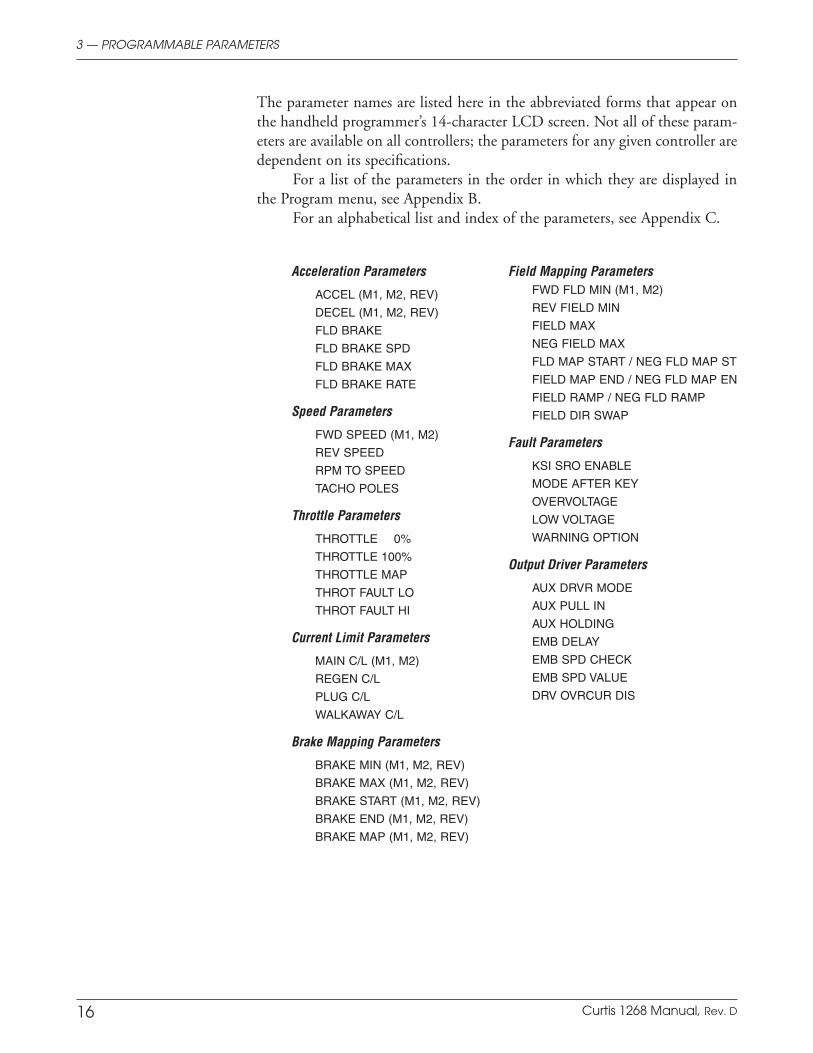
The parameter names are listed here in the abbreviated forms that appear on the handheld programmer’s 14-character LCD screen. Not all of these param-eters are available on all controllers; the parameters for any given controller are dependent on its specifications.
For a list of the parameters in the order in which they are displayed in the Program menu, see Appendix B.
For an alphabetical list and index of the parameters, see Appendix C.
3 — PROGRAMMABLE PARAMETERS
17Curtis 1268 Manual, Rev. D
3 — PROGRAMMABLE PARAMETERS: Acceleration Parameters
M1/M2/REV ACCEL RATE
The acceleration rate defines the time, in seconds, for the controller to ac-celerate from 0% output to 100% output. A larger value represents a longer acceleration time and a gentler start. Fast starts can be achieved by reducing the acceleration time, i.e., by adjusting the accel rate to a smaller value. The forward accel rate can be set independently for each of the two operating modes; the reverse accel rate applies to both M1 and M2.
M1/M2/REV DECEL RATE
The deceleration rate defines the time, in seconds, for the controller to reduce the average voltage at the armature output from 100% PWM to 0% PWM. A larger value represents a longer deceleration time and gentler vehicle slow-ing. Quick stops can be achieved by reducing the deceleration time, i.e., by adjusting the decel rate to a smaller value. The forward decel rate can be set independently for each of the two operating modes; the reverse decel rate ap-plies to both M1 and M2.
If the vehicle is slowing quicker than the decel rate (for example, at zero throttle, traveling up a hill) the output will decay at a rate of 0.8 seconds.
FLD BRAKE
The field brake parameter enables or disables the field braking function. When set to On, the field brake routine is enabled and will increase the vehicle brak-ing near zero speed.
Related parameters: When FLD BRAKE is On, the Field Brake SPD, MAX, and RATE parameters apply; they have no effect when FLD BRAKE is programmed Off.
FLD BRAKE SPD
The field brake speed parameter sets the speed threshold below which field braking will occur when FLD BRAKE is On. When the throttle has been released and vehicle speed is detected to have fallen below FLD BRAKE SPD, the field current starts to increase toward the value specified by FLD BRAKE MAX at a rate specified by FLD BRAKE RATE. If the threshold speed is set very low, field braking will occur only at the very end of vehicle deceleration. If the vehicle does not slow to the speed defined by FLD BRAKE SPD (down a steep hill, for example) field braking will not occur as the threshold will not be reached.
Acceleration Parameters

18 Curtis 1268 Manual, Rev. D
FLD BRAKE MAX
The field brake max parameter sets the maximum value of field current per-mitted during field braking when FLD BRAKE is On. The field current defined by FLD BRAKE MAX overrides the standard field map current below the speed defined by FLD BRAKE SPD.
When an EM brake is used, the amount of field current programmed by FLD BRAKE MAX is applied for the max amount of time specified by EMB DELAY (see Output Driver parameters) prior to locking the EM brake. A high value of FLD
BRAKE MAX helps to ensure the vehicle uses sufficient braking to slow to a stop before locking the EM brake.
When the auxiliary output is used for a WalkAway relay™ instead of an EM brake, lower FLD BRAKE MAX values are useful in providing softer braking near zero speed. Setting the value too low may render the controller incapable of sensing vehicle rollback. However, even though the anti-rollback function may not be activated, the plug braking generated by the field current will still act to slow the vehicle.
FLD BRAKE RATE
The field brake rate parameter defines how quickly the field current rises during field braking when FLD BRAKE is On, and is adjustable from 0 to 6. This index value defines the time for the field current to rise to the programmed FLD BRAKE
MAX, as shown in the examples below. The higher the setting, the faster the rise. (In these examples, FLD BRAKE MAX = 50.0 amps.)
INDEX FIELD CURRENT RANGE TIME OF RISE
1 0.0 – 50.0 A 3.2 seconds
6 0.0 – 50.0 A 0.5 seconds
When an EM brake is used, the field current rises until it reaches FLD BRAKE
MAX, maintains that current for the duration of EMB DELAY, at the end of which the EM brake driver turns off, causing the brake to engage—if it has not already been applied due to the vehicle having stopped or started to roll back.
3 — PROGRAMMABLE PARAMETERS: Acceleration Parameters
ST
RO
NG
ER
BR
AK
ING

19Curtis 1268 Manual, Rev. D
M1/M2 FWD SPEED
The forward speed parameter defines the maximum speed limit in the forward direction. It is adjustable from 4.0 to 40.0, in units of mph or km/h (depending on RPM TO SPEED the setting).
REV SPEED
The reverse speed parameter defines the maximum speed limit in the reverse direction. It is adjustable from 4.0 to 16.0, in units of mph or km/h (depend-ing on RPM TO SPEED the setting).
RPM TO SPEED
The rpm to speed parameter is a conversion factor used to generate a vehicle speed estimate from the speed sensor input (motor RPM signal). Use these equations to calculate the value to enter for RPM TO SPEED:
For English units (mph): tire diameter (inches) × 63 gear ratio
For metric units (km/h): tire diameter (cm) × 40 gear ratio
TACHO POLES
The tachometer poles parameter configures the speed sensor, and should be set to the number of magnetic poles in the speed sensor magnet. TACHO POLES is adjustable from 4 to 20; see speed sensor description (page 14) for information about sensor types.
3 — PROGRAMMABLE PARAMETERS: Speed Parameters
Speed Parameters

20 Curtis 1268 Manual, Rev. D
THROTTLE 0%
The throttle 0% parameter defines the throttle input voltage at which a throttle command begins. Voltages lower than the programmed value (but higher than THRTL FAULT LO) are interpreted to be in a 0% deadband.
THROTTLE 100%
The throttle 100% parameter defines the throttle input voltage that gives a full throttle command. Input voltages above this value (but lower than THRTL FAULT
HI) are interpreted as 100% throttle command.
THROTTLE MAP
The throttle map parameter modifies the vehicle’s response to the throttle input. As shown in Figure 7, this parameter determines the controller output for a given amount of applied throttle. The THROTTLE MAP setting refers to the controller output at half throttle, the midpoint of the throttle’s full active range (the range between THROTTLE 0% and THROTTLE 100%).
3 — PROGRAMMABLE PARAMETERS: Throttle Parameters
Throttle Parameters
Fig. 7 Throttle maps for controller with the Throttle Map parameter set at vari-ous values.
Setting THROTTLE MAP at 50% provides a linear output response to throttle position. Values below 50% reduce the controller output at low throttle settings, providing enhanced slow speed control. Values above 50% give the vehicle a faster, jumpier feel at low throttle settings.
Controller output begins when the throttle is moved beyond THROTTLE 0%, and continues to increase—following the curve defined by the THROTTLE MAP setting—as the throttle input increases, and reaches maximum output when the throttle input crosses the THROTTLE 100% threshold.
21Curtis 1268 Manual, Rev. D
THROT FAULT LO
The throttle fault low parameter sets the lower throttle fault threshold; throttle input voltages below this threshold will signal a throttle fault.
THROT FAULT HI
The throttle fault high parameter sets the upper throttle fault threshold; throttle input voltages above this threshold will signal a throttle fault.
3 — PROGRAMMABLE PARAMETERS: Current Limit Parameters
Current Limit Parameters
M1/M2 MAIN C/L
The main current limit parameter allows adjustment of the maximum current the controller will supply to the motor during drive operation. This parameter can be used to reduce the maximum torque applied to the drive system by the motor in either of the modes. The drive current limit is adjustable from 100 amps up to the controller’s full rated current. The full rated current depends on the controller model.
REGEN C/L
The regenerative current limit parameter allows adjustment of the maximum current the controller will supply to the motor during regen braking opera-tion. During regen braking, this parameter controls the regen current from the motor’s armature into the battery. The braking current limit is adjustable from 0 amps up to the controller’s full rated current. The full rated current depends on the controller model.
Regen is the normal mode of braking.
PLUG C/L
The plug current limit parameter allows adjustment of the maximum current the controller will supply to the motor during plug braking operation. During plug braking, this parameter controls the plug current from the motor’s armature. The plug current limit is adjustable from 0 amps up to the controller’s full rated current. The full rated current depends on the controller model.
Plug braking is used during WalkAway™ and Anti-Rollback operation.
WALKAWAY C/L
The WalkAway current limit parameter sets the maximum field current applied during WalkAway™ operation. The WalkAway™ function applies field current to slow a vehicle that is detected as moving while the main contactor is open. The motor force created from this function is intended to limit the vehicle’s rolling speed, but may not be sufficient to slow heavy vehicles on steep

22 Curtis 1268 Manual, Rev. D
slopes. The warning buzzer is pulsed to create an audible indication that the vehicle is rolling.
The brake mapping parameters determine the maximum braking power that can be applied at a given vehicle speed. BRAKE MAX should be set higher than BRAKE MIN, and BRAKE END higher than BRAKE START.
M1/M2/REV BRAKE MIN
The brake minimum parameter sets the max regen current at low speeds, and is applicable from BRAKE START speed to zero speed. The value is a percentage of the full regen current.
BRAKE MIN is used to soften vehicle braking at low speeds. A low value will limit the braking at low speeds to provide a soft deceleration. A very low value may prevent the vehicle from coming to a stop from pedal-up braking on an incline, while a very high value may cause the vehicle to brake abruptly.
M1/M2/REV BRAKE MAX
The brake maximum parameter is used to set the max regen current at high speeds, and is applicable at speeds at and above the BRAKE END speed. The value is a percentage of the full regen current.
BRAKE MAX is used to strengthen vehicle braking at high speeds. A high value will provide greater braking power at high speeds. A very low value may prevent the vehicle from successfully limiting speed down a hill, while a very high value may cause excessive braking force at high speeds.
M1/M2/REV BRAKE START
The brake map start parameter defines the vehicle speed at which the brake map starts to increase from the BRAKE MIN value. Increasing the BRAKE START value increases the speed at which the controller’s braking power reaches the BRAKE
MIN setting, resulting in a larger speed range with soft braking.
M1/M2/REV BRAKE END
The brake map end parameter defines the vehicle speed at which the brake map reaches the BRAKE MAX value. This parameter can be set to allow the controller to use a higher braking power at higher speeds.
Decreasing the BRAKE END value increases the braking torque the vehicle can produce at medium speeds.
3 — PROGRAMMABLE PARAMETERS: Brake Mapping Parameters
Brake Mapping Parameters
23Curtis 1268 Manual, Rev. D
3 — PROGRAMMABLE PARAMETERS: Brake Mapping Parameters
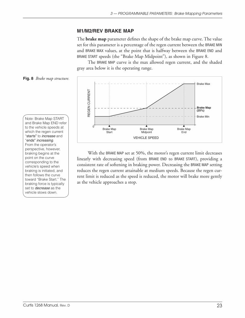
Fig. 8 Brake map structure.
Note: Brake Map START and Brake Map END refer to the vehicle speeds at which the regen current “starts” to increase and “ends” increasing. From the operator’s perspective, however, braking begins at the point on the curve corresponding to the vehicle’s speed when braking is initiated, and then follows the curve toward “Brake Start.” The braking force is typically set to decrease as the vehicle slows down.
M1/M2/REV BRAKE MAP
The brake map parameter defines the shape of the brake map curve. The value set for this parameter is a percentage of the regen current between the BRAKE MIN and BRAKE MAX values, at the point that is halfway between the BRAKE END and BRAKE START speeds (the “Brake Map Midpoint”), as shown in Figure 8.
The BRAKE MAP curve is the max allowed regen current, and the shaded gray area below it is the operating range.
With the BRAKE MAP set at 50%, the motor’s regen current limit decreases linearly with decreasing speed (from BRAKE END to BRAKE START), providing a consistent rate of softening in braking power. Decreasing the BRAKE MAP setting reduces the regen current attainable at medium speeds. Because the regen cur-rent limit is reduced as the speed is reduced, the motor will brake more gently as the vehicle approaches a stop.
24 Curtis 1268 Manual, Rev. D
The field mapping parameters determine how much field current is applied for a given armature current.
M1/M2 FWD FIELD MIN
The forward minimum field current limit parameter defines the minimum allowed current in the motor’s field winding when the vehicle is traveling in the forward direction. Its setting may affect the vehicle’s maximum speed and, to some extent, the smoothness with which the vehicle starts and transitions between drive and regen. If FWD FIELD MIN is set high, the vehicle’s top speed will be reduced, but torque bumps may be evident when the vehicle is inched or changes direction.
One of the greatest advantages of the FIELD MIN parameter is that it will prevent uncontrolled acceleration when the vehicle goes down ramps or when it is unloaded from trucks, etc.
REV FIELD MIN
The reverse minimum field current limit parameter defines the minimum allowed current in the motor’s field winding when the vehicle is traveling in the reverse direction.
FIELD MAX
The maximum field current limit parameter defines the maximum allowed current in the motor’s field winding. Its setting will determine the motor’s maximum torque during drive operation, and will limit the power dissipation in the field winding itself.
NEG FIELD MAX
The negative maximum field current limit parameter defines maximum al-lowed current in the motor’s field winding during regen braking.
FLD MAP START / NEG FLD MAP ST
The field map start parameter defines the armature current at which the field current starts to increase from the FIELD MIN value (see current limit parameters). The negative field map start parameter works similarly; it defines the negative armature current at which the field current starts to increase from the FIELD MIN value.
Care should be taken to ensure that high FIELD MAP START values do not move the motor’s operating characteristics outside its safe commutation area.
3 — PROGRAMMABLE PARAMETERS: Field Mapping Parameters
Field Mapping Parameters
25Curtis 1268 Manual, Rev. D
FIELD MAP END / NEG FLD MAP EN
The field map end parameter defines the armature current at which the field map clamps to the FIELD MAX value (see current limit parameters).
Care should be taken to ensure that high FIELD MAP END values do not move the motor’s operating characteristics outside its safe commutation region.
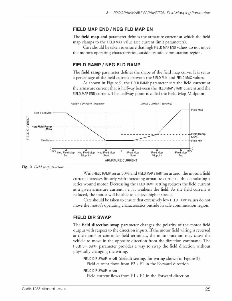
FIELD RAMP / NEG FLD RAMP
The field ramp parameter defines the shape of the field map curve. It is set as a percentage of the field current between the FIELD MIN and FIELD MAX values.
As shown in Figure 9, the FIELD RAMP parameter sets the field current at the armature current that is halfway between the FIELD MAP START current and the FIELD MAP END current. This halfway point is called the Field Map Midpoint.
3 — PROGRAMMABLE PARAMETERS: Field Mapping Parameters
Fig. 9 Field map structure.
With FIELD RAMP set at 50% and FIELD MAP START set at zero, the motor’s field current increases linearly with increasing armature current—thus emulating a series wound motor. Decreasing the FIELD RAMP setting reduces the field current at a given armature current, i.e., it weakens the field. As the field current is reduced, the motor will be able to achieve higher speeds.
Care should be taken to ensure that excessively low FIELD RAMP values do not move the motor’s operating characteristics outside its safe commutation region.
FIELD DIR SWAP
The field direction swap parameter changes the polarity of the motor field output with respect to the direction inputs. If the motor field wiring is reversed at the motor or controller field terminals, the motor rotation may cause the vehicle to move in the opposite direction from the direction command. The FIELD DIR SWAP parameter provides a way to swap the field direction without physically changing the wiring.
FIELD DIR SWAP = off (default setting, for wiring shown in Figure 3)Field current flows from F2 » F1 in the Forward direction.
FIELD DIR SWAP = on Field current flows from F1 » F2 in the Forward direction.

26 Curtis 1268 Manual, Rev. D
KSI SRO ENABLE
The keyswitch static return to off (SRO) feature prevents the vehicle from be-ing started when “in gear.” When this parameter is enabled, the controller must initially sense the KSI input in the Off position (upon vehicle power-up) prior to it being switched to the On position. This feature is used to prevent vehicle motion due to a KSI short circuit or due to the keyswitch being permanently locked in the On position.
MODE AFTER KEY
The mode change after keyswitch parameter determines whether the operat-ing mode (M1, M2) can be changed after KSI has been activated. If MODE AFTER
KEY is enabled, the mode can be changed while the vehicle is being operated. The settings are gradually slewed between the two modes so as to reduce the abruptness of the transition. However, if the settings for Mode 1 greatly differ from those of Mode 2, switching from one mode to the other while driving may cause the vehicle performance to change drastically.
If MODE AFTER KEY is not enabled, the mode can be changed only when keyswitch is off.
OVERVOLTAGE
The overvoltage parameter sets the overvoltage protection threshold for the electronic system. This parameter determines when regen should be cut back to prevent damage to batteries and other electrical system components due to overvoltage. A non-adjustable internal threshold also exists, to prevent damage within the controller.
LOW VOLTAGE
The low voltage parameter sets the undervoltage threshold to protect the system from operating at voltages lower than its electronics were designed for. At this threshold voltage, the drive current will taper off until it reaches the controller’s internal threshold for safe operation. This will ensure proper operation of all electronics whenever the vehicle is driven.
3 — PROGRAMMABLE PARAMETERS: Fault Parameters
Fault Parameters
27Curtis 1268 Manual, Rev. D
WARNING OPTION
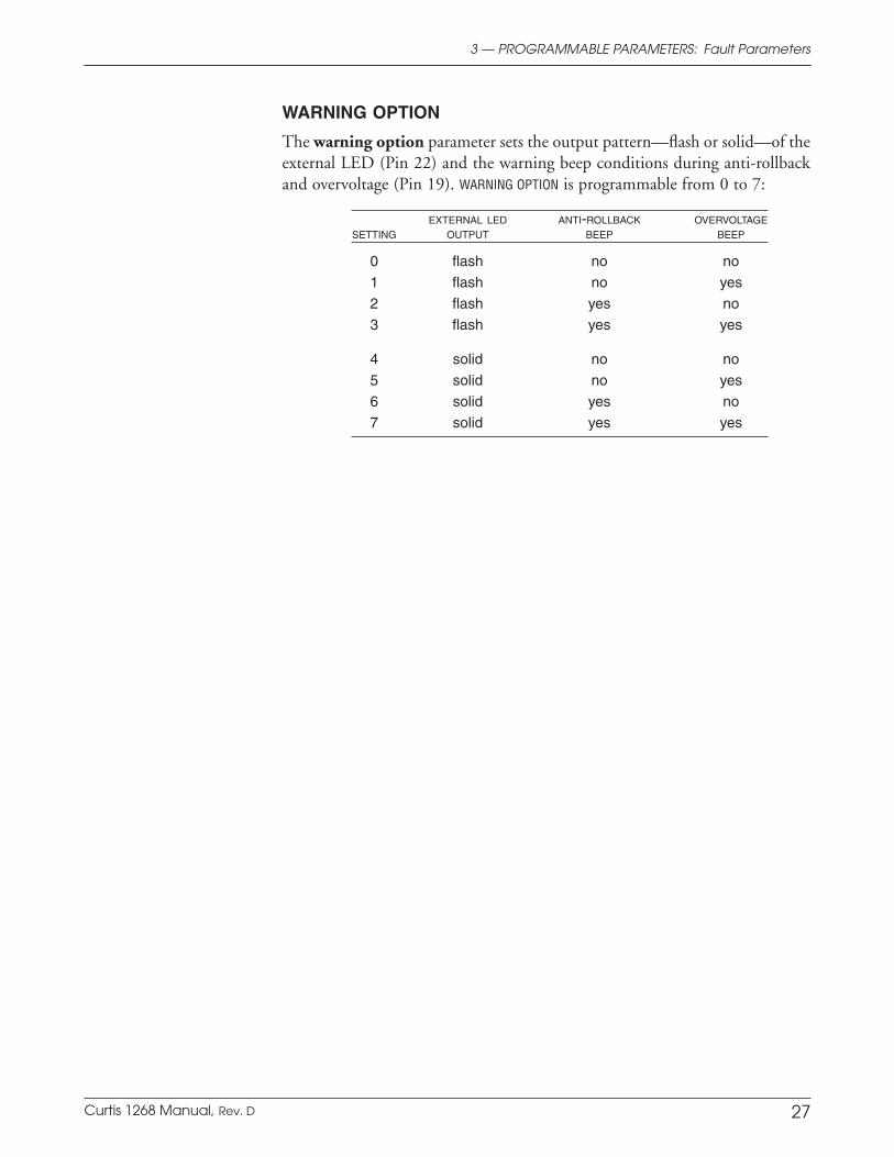
The warning option parameter sets the output pattern—flash or solid—of the external LED (Pin 22) and the warning beep conditions during anti-rollback and overvoltage (Pin 19). WARNING OPTION is programmable from 0 to 7:
EXTERNAL LED ANTI-ROLLBACK OVERVOLTAGE SETTING OUTPUT BEEP BEEP
0 flash no no
1 flash no yes
2 flash yes no
3 flash yes yes
4 solid no no
5 solid no yes
6 solid yes no
7 solid yes yes
3 — PROGRAMMABLE PARAMETERS: Fault Parameters

28 Curtis 1268 Manual, Rev. D
AUX DRVR MODE
The auxiliary driver mode parameter determines whether the auxiliary function will be an electromagnetic brake or a WalkAway™ relay or neither (no auxiliary function). It is programmable from 0 to 2:
0 auxiliary driver Off
1 external WalkAway relay
2 electromagnetic brake
A WalkAway™ relay provides an alternative path for the current to the controller so that it can maintain braking to slow a vehicle that begins to roll after the main contactor has opened.
An EM brake keeps the vehicle from moving after coming to rest, which can be very useful when stopping on a hill.
Both options require appropriate hardware. See the wiring diagrams, pages 8 and 9.
AUX PULL IN
The auxiliary pull-in voltage parameter sets the peak voltage momentarily applied to the load connected to the aux driver. The pull-in parameter allows a high initial voltage to be supplied for 0.1 second when the driver first turns on, to ensure proper closure. Values for this parameter should be determined from relay/EMB specifications or advice from the device manufacturer.
AUX PULL IN is programmable from 1 to 3, representing these fixed battery voltage percentages:
1 100% battery voltage
2 60% battery voltage
3 35% battery voltage
AUX HOLDING
The auxiliary holding voltage parameter sets the continuous voltage applied to the load connected to the aux driver, after the initial 0.1 second pull-in.
AUX HOLDING is programmable from 1 to 3. The driver output is pulse width modulated at one of three battery voltage percentages:
1 100% battery voltage
2 60% battery voltage
3 35% battery voltage
Using this parameter, the average applied voltage can be reduced so that a coil that is not rated for the full battery voltage can be used. For example, a relay coil rated for 24V could be used in a 48V system if AUX HOLDING is set to 3 (48V * 0.35 = 16.8V), as 16.8V is well above typical dropout voltage. The
3 — PROGRAMMABLE PARAMETERS: Output Driver Parameters
Output Driver Parameters
29Curtis 1268 Manual, Rev. D
resulting voltage must be set high enough to hold the relay closed under all shock and vibration conditions the vehicle will be subjected to. Low settings minimize the current required to power the coil, thereby reducing coil heating and increasing battery life.
Values for AUX HOLDING should be determined with specifications or advice from the relay or brake manufacturer.
Example: To use a 24V brake in a 48V vehicle, try
AUX PULL IN = 2 (28.8V)
AUX HOLDING = 3 (16.8V)
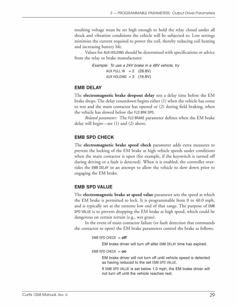
EMB DELAY
The electromagnetic brake dropout delay sets a delay time before the EM brake drops. The delay countdown begins either (1) when the vehicle has come to rest and the main contactor has opened or (2) during field braking, when the vehicle has slowed below the FLD BRK SPD.
Related parameter: The FLD BRAKE parameter defines when the EM brake delay will begin—see (1) and (2) above.
EMB SPD CHECK
The electromagnetic brake speed check parameter adds extra measures to prevent the locking of the EM brake at high vehicle speeds under conditions when the main contactor is open (for example, if the keyswitch is turned off during driving or a fault is detected). When it is enabled, the controller over-rides the EMB DELAY in an attempt to allow the vehicle to slow down prior to engaging the EM brake.
EMB SPD VALUE
The electromagnetic brake at speed value parameter sets the speed at which the EM brake is permitted to lock. It is programmable from 0 to 40.0 mph, and is typically set at the extreme low end of that range. The purpose of EMB
SPD VALUE is to prevent dropping the EM brake at high speed, which could be dangerous on certain terrain (e.g., wet grass).
In the event of main contactor failure (or fault detection that commands the contactor to open) the EM brake parameters control the brake as follows.
EMB SPD CHECK = off
EM brake driver will turn off after EMB DELAY time has expired.
EMB SPD CHECK = on
EM brake driver will not turn off until vehicle speed is detected as having reduced to the set EMB SPD VALUE.
If EMB SPD VALUE is set below 1.0 mph, the EM brake driver will not turn off until the vehicle reaches rest.
3 — PROGRAMMABLE PARAMETERS: Output Driver Parameters
30 Curtis 1268 Manual, Rev. D
3 — PROGRAMMABLE PARAMETERS: Output Driver Parameters
DRV OVRCUR DIS
The driver overcurrent detection disable parameter disables the controller’s driver overcurrent detection. The overcurrent detection mechanism acts to protect the main contactor and auxiliary drivers in the event they are con-nected to a load with too little resistance. This can occur due to miswiring or a defective peripheral device. For example, a fault condition could occur from a direct connection to B+ or from a short in the windings of a contactor coil or EM brake. In such cases, the controller must recognize the condition quickly and turn the driver Off before it is permanently damaged by excessive current.However, because of the speed of the detection, electrical noise (which the con-troller is subjected to during EMI testing) may cause the detection mechanism to trigger a nuisance fault.
DRV OVRCUR DIS = off (default setting)When the parameter is programmed Off, overcurrent detection is not disabled, and the controller will detect an overcurrent situation.
DRV OVRCUR DIS = onWhen the parameter is programmed On, overcurrent detection is disabled. This leaves the main contactor and auxiliary drivers unpro-tected from coil shorts and miswiring. However, it may be desirable to set the parameter On temporarily during EMI testing.
Curtis 1268 Manual, Rev. D 31
4 — INSTALLATION CHECKOUT
4
☞C A U T I O N
INSTALLATION CHECKOUT
Before operating the vehicle, carefully complete the following checkout proce-dure. If you find a problem during the checkout, refer to the diagnostics and troubleshooting section (Section 6) for further information.
The installation checkout can be conducted with or without a program-mer. The checkout procedure is easier with a programmer. Otherwise, observe the Status LED (located in the controller’s label area) for diagnostic codes. The codes are listed in Section 6.
Put the vehicle up on blocks to get the drive wheels up off the ground before beginning these tests.
Do not stand, or allow anyone else to stand, directly in front of or behind the vehicle during the checkout.
Make sure the keyswitch is off, the throttle is released, and the forward and reverse switches are open.
Wear safety glasses and use well-insulated tools.
1. If a programmer is available, connect it to the programmer connector.
2. Turn the run/store switch on. The programmer should power up with an initial display. If it does not, check for continuity in the run/store switch circuit and controller ground.
If a programmer is not available, controller power-up can be veri-fied by momentarily selecting reverse and listening for the sound of the reverse alarm.
3. If you are using a programmer, go to the Faults Menu. The display should indicate “No Known Faults.”
If there is a problem, the LED will flash a diagnostic code and the programmer will display a diagnostic message. If you are conducting the checkout without a programmer, look up the LED diagnostic code in Section 6: Diagnostics and Troubleshooting.
When the problem has been corrected, it may be necessary to cycle the run/store switch in order to clear the fault.
4. Turn the keyswitch on, select a direction, and operate the throttle. The motor should begin to turn in the selected direction. If it turns in the wrong direction, first verify the wiring to the forward and reverse switches. If the direction switch wiring is correct, turn off the controller,
32 Curtis 1268 Manual, Rev. D
disconnect the battery, and exchange the motor’s field connections (F1 and F2) on the controller. The motor should now turn in the proper direction. If you are using a programmer, you can use the parameter FIELD
DIR SWAP to change the motor field output without physically changing the wiring (see page 25).
The motor should run proportionally faster with increasing throttle. If it does not, refer to Section 6.
5. If you are using a programmer, go to the Monitor menu. Scroll down to observe the status of the switches:
Mode * Foot Input (pedal switch) Key Input Forward Input Reverse Input Mode Switch * Cycle each switch in turn, observing the programmer. The programmer
should display the correct status for each switch.
* “Mode Switch” tells you the physical status of the mode switch (open or closed). “Mode” is a monitor value that tells you the mode in which the vehicle is currently operating. This may not correspond to the status of the mode switch—for example, if the MODE AFTER KEY parameter is set to Off and the mode switch was flipped while the vehicle was being operated.
6. Take the vehicle down off the blocks and drive it in a clear area. It should have smooth acceleration and good top speed. Recommended procedures for tuning the vehicle’s driving characteristics are presented in Section 5: Tuning Guide.
7. Test the deceleration and braking of the vehicle.
8. Verify that all options, such as static return to off (SRO), electromagnetic brake (or WalkAway™), and reverse signal are as desired.
9. If you used a programmer, disconnect it when you have completed the checkout procedure, to minimize battery discharge.
4 — INSTALLATION CHECKOUT
Curtis 1268 Manual, Rev. D 33
5 — TUNING GUIDE
5 TUNING GUIDE
The 1268 controller is a very powerful vehicle control system. Its wide variety of adjustable parameters allow many aspects of vehicle performance to be opti-mized. This section provides explanations of what the major tuning parameters do and instructions on how to use these parameters to optimize the performance of your vehicle. Once a vehicle/motor/controller combination has been tuned, the parameter values can be made standard for that system or vehicle model. Any changes in the motor, the vehicle drive system, or the controller will require that the system be tuned again to provide optimum performance.
The tuning procedures should be conducted in the sequence given, because successive steps build upon the ones before. The tuning procedures instruct per-sonnel how to adjust various programmable parameters to accomplish specific performance goals. It is important that the effect of these programmable pa-rameters be understood in order to take full advantage of the 1268 controller’s powerful features. Please refer to the descriptions of the applicable parameters in Section 3 if there is any question about what any of them do.
MAJOR TUNING
Five major performance characteristics are usually tuned on a vehicle:
1 Tuning the Active Throttle Range
2 Calibrating the Controller Speed Measurement
3 Tuning the Controller to the Motor (Field Mapping)
4 Equalizing Loaded/Unloaded Vehicle Speed on Flat Ground
5 Confirming Loaded Vehicle Speed on Downhill Grade.
These five characteristics should be tuned in the order listed.
1 Tuning the Active Throttle Range
Before attempting to optimize any specific vehicle performance characteristics, it is important to ensure that the controller input is operating over its full range. To do this, the throttle should be tuned using the handheld programmer and a voltmeter. The procedures that follow will establish zero throttle, full throttle, and throttle fault parameter values that correspond to the absolute full range of your particular throttle mechanism. Note: These parameters are expressed in absolute voltages between 0 and 5 volts.
It is advisable to provide some buffer around the absolute full range of the throttle mechanism to allow for throttle resistance variations over time and temperature as well as variations in the tolerance of potentiometer values between individual throttle mechanisms. This will form areas at the top and bottom of the throttle movement range that the controller reads as 0% and 100%.
34 Curtis 1268 Manual, Rev. D
step 1. Jack the vehicle wheels up off the ground so that they spin freely. Note: Most of the throttle tuning can be done without driving the motor, but it is advisable to check that the throttle range is still fully active when motor currents are being produced.
step 2. Plug the 1311 programmer into the controller and turn on the controller with the run/store switch.
step 3. Using the programmer’s Program menu, initially set the THROTTLE MAP parameter to 50%. This will provide a lin-ear relationship between the throttle input voltage and the Throttle % displayed in the programmer’s Monitor menu.
step 4. Select the Monitor menu. Throttle % should be visible at the top of the display. You will need to reference the value displayed here.
step 5. Use a voltmeter and test clip to measure the throttle input volt-age at Pin J1-15.
step 6. Measure and note the voltage when the throttle is fully released.
step 7. If the pedal switch is wired into the mechanical throttle mechanism, scroll down the Monitor menu to Foot Input. The display should indicate that the pedal switch is Off. Slowly apply throttle until the display indicates that the pedal switch is On. Measure the throttle voltage that is be-ing produced at this threshold, and make a note of this value.
step 8. Measure the voltage when the throttle is fully depressed, and make a note of this value.
step 9. Return to the Program menu. Set THROT FAULT LO lower than the fully released voltage mea-
sured in Step 6. If the pedal switch is wired into the throttle mechanism,
set THROTTLE 0% close to the voltage measured in Step 7. (Setting THROTTLE 0% too far below this voltage will result in loss of low-end throttle range.) If the pedal switch is not part of the throttle assembly, set THROTTLE 0% above the fully released voltage measured in Step 6.
Set THROTTLE 100% lower than the fully depressed voltage measured in Step 8. Set the THROT FAULT HI parameter above the fully depressed voltage (but no higher than 4.7 V).
step 10. Apply the keyswitch and forward switch and depress the throttle slowly through the full range of motion, causing the wheels to spin. Ensure that the Throttle % reaches 100% when the pedal is fully depressed. Ensure that the Throttle % returns to 0% when the throttle is released and that no throttle fault appears in the Faults menu.
step 11. Refer to Section 3, page 20, and set the THROTTLE MAP parameter for desired performance.
5 — TUNING GUIDE
Curtis 1268 Manual, Rev. D 35
2 Calibrating the Controller Speed Measurement to the Vehicle
The RPM TO SPEED parameter is a conversion factor used to generate a vehicle speed estimate from the speed sensor input (motor RPM signal). This conver-sion factor allows the vehicle to be configured for various gear ratios and tire sizes. It can also be used to convert the displayed vehicle speed values (in the Program and Monitor menus) between English and metric units. Use the equa-tions below to calculate the correct value for this parameter.
For English units (mph): tire diameter (inches) × 63 gear ratio
For metric units (km/h): tire diameter (cm) × 40 gear ratio
step 1. Using the Program menu, set RPM TO SPEED to the correct value for the vehicle tire size and gear ratio.
step 2. Set TACHO POLES To the number of poles in the motor’s speed sensor (typically 8).
step 3. Set the M1 FWD SPEED, M2 FWD SPEED and REVERSE SPEED to the desired top vehicle speeds (in either mph or km/h).
3 Tuning the Controller to the Motor
The 1268 controller has the flexibility to be tuned to nearly any separately excited motor from any manufacturer. The programmable parameters allow full control of the motor’s maximum armature current during driving and braking; they also allow full control of the motor’s maximum and minimum field current as well as the field current relationship to the armature current. This flexibility allows motor performance to be maximized while protecting it from operating outside its safe commutation region.
In order to properly tune the controller, the following information should be obtained from the motor manufacturer:
Maximum Armature Current Rating
Maximum Field Current Rating
Minimum Field Current Rating
Field Resistance (hot and cold)
Positive and Negative Field Maps.
The performance of a separately excited motor changes depending on tem-perature. This is due to the change in field winding resistance as the motor heats up through use. When the field winding temperature increases, so does its resistance and therefore the maximum current that can be forced through
5 — TUNING GUIDE
36 Curtis 1268 Manual, Rev. D
the winding is reduced. Reductions in the field current over the motor’s typical operating temperature range can be 10% to 50%. Since the maximum avail-able field current determines the maximum torque that can be produced by the motor, the vehicle’s performance under load and up inclines will change as the motor heats up. The change in performance can be limited by tuning the motor when it is hot rather than cold. We therefore recommend that this procedure be performed with a hot motor.
step 1. Using the programmer’s Program Menu, set the drive current limit (MAIN C/L) for both modes to the smaller of: (a) the motor’s peak armature current rating, or (b) the maximum controller drive current limit. This value can later be adjusted to establish the desired vehicle driving feel in each mode.
step 2. Set the REGEN C/L value in each mode to the smaller of: (a) the maximum motor armature current rating, or (b) the maximum controller braking current limit. This value can later be adjusted to establish the desired vehicle braking feel (see Fine Tuning).
step 3. To set FIELD MAX, first decide whether you want to maintain con-sistent vehicle operation throughout the motor’s temperature range. If you do, proceed to Step 4. If, however, maintaining operational consistency across motor temperature is not a concern and achieving maximum torque is, skip to Step 5.
step 4. For the most consistent operation across temperature, set the FIELD MAX to the maximum field current available at low battery voltage with a hot motor. To determine this current, divide the low battery voltage (typically 70% of nominal) by the high temperature field winding resistance specification provided by the manufacturer. Set FIELD MAX to this value. This will provide good consistency between motor performance in both hot and cold states. Skip to Step 6.
step 5. For the maximum torque regardless of temperature, set FIELD MAX to the motor’s rated absolute maximum field current. To deter-mine the absolute maximum field current, divide the nominal battery voltage by the low temperature field winding resistance specification provided by the manufacturer. Set FIELD MAX to this value. This will provide the maximum possible torque under all conditions.
This has now set the FIELD MAX parameter. The next step is to set the FIELD MIN parameter. FIELD MIN should never be set below the rated value specified by the manufacturer. Operating the motor at lower field currents than specified will result in operation outside the motor’s safe commutation region and will cause arcing between the brushes and com-mutator, significantly reducing motor and brush life.
5 — TUNING GUIDE

Curtis 1268 Manual, Rev. D 37
step 6. Set NEG FIELD MAX at or below the FIELD MAX setting. If the controller is tuned such that the system is operating
outside the motor’s safe commutation region, there will be au-dible and visual indications. Under normal operation, the mo-tor will emit a whine with a pitch that increases with increasing rotation speed. If a “scratchy” sound is also heard, this is usually an indication that pin arcing is occurring in the motor and it is operating outside its safe commutation region. This operation is normally accompanied by a strong smell from the motor. If the brushes and commutator bars are visible, arcing may be visible. The further outside the safe commutation region the motor is operating, the worse the arcing will be. Operation outside the safe commutation region is very detrimental to the motor. The FIELD MIN and possibly also the FIELD RAMP should be increased until the indications of arcing stop. Decreasing FIELD MAP START will also help to move operation back into the safe commutation region.
The typical default field map settings are as follows.
5 — TUNING GUIDE
Further tuning of the field maps is described in procedures 5, 7, and 9.
38 Curtis 1268 Manual, Rev. D
4 Equalizing the Loaded/Unloaded Vehicle Top Speed on Flat Ground
The controller and vehicle should be configured as follows prior to setting the maximum vehicle speed:
• DRIVE C/L as established in tuning procedure 3
• FIELD RAMP = 50%
• FLD MAP START = 20% of the specified drive current limit
• FIELD MIN = manufacturer’s specified minimum or 3 amps
• The vehicle can be loaded or loaded
If full closed loop speed control is required in both loaded and unloaded operation, conduct this procedure with the vehicle loaded.
• The vehicle battery should be fully charged.
Drive the vehicle on a flat surface in a clear area during this procedure. Precautions should be taken to ensure safety of test personnel and anyone in the test area.
step 1. Select the programmer’s Program menu and scroll down until M1 FWD SPEED parameter is displayed, and set this to the desired top forward speed for Mode 1. Confirm that Mode 1 is selected by reading the Mode value in the Monitor menu.
step 2. Turn on the keyswitch and the Forward switch and apply full throttle. While driving the vehicle with full throttle applied, ob-serve the Speed In and Arm PWM readings in the Monitor menu. (Note: vehicle speed will display as 0.8 for speeds below 1.0.)
If the speed is being limited by the field map parameters, the Arm PWM will be 100%. In this case, skip to Step 4.
If the vehicle is truly in closed loop speed control, the Arm PWM will be less than 100%. The controller will be limiting the vehicle speed to the programmed maximum speed by reducing the applied armature voltage below the value commanded by the throttle. In this case, proceed to Step 3.
step 3. Observe the Arm PWM and Arm Current readings while driving at top speed. Set the FLD MAP START to a value above the Arm Cur-rent reading. With the vehicle unloaded, increase the M1 FWD FLD
MIN until the Arm PWM is between 60–70%. When the vehicle is loaded the controller will output a higher value of Arm PWM to achieve this speed.
For slow speeds, a higher FIELD MIN is preferable, in order to ensure a smooth transition between the drive and regen states. For high speeds, a lower FIELD MIN is usually necessary to allow the vehicle to achieve true closed loop speed control and not be limited by the field current.
Skip to Step 5.
5 — TUNING GUIDE

Curtis 1268 Manual, Rev. D 39
step 4. In this case, the vehicle’s top speed is being limited by the field mapping parameters. Observe the Arm Current in the Monitor menu, and set the FIELD MAP START to a value above the Arm Cur-rent reading. Reduce the M1 FWD FLD MIN until the Speed Input shows the programmed maximum speed (i.e., the speed set by M1 FWD SPEED) and the Arm PWM reading drops below 100%, indicating that the controller is in closed loop speed control. When the vehicle is unloaded the controller will output a lower value of Arm PWM to maintain this speed.
Do not set the field mapping parameters outside the motor’s safe commutation limits.
step 5. Repeat from Step 1 for the Mode 2 forward speed and for reverse speed. Separate field minimum parameters are provided for all three speeds (M1 FWD SPEED, M2 FWD SPEED, REV SPEED).
5 Confirming Loaded Vehicle Speed on Downhill Grade
step 1. Set the following parameters:
• REGEN C/L = maximum specified by the motor specs
• NEG FLD MAP EN = at or below REGEN C/L
• NEG FIELD MAX = FIELD MAX (as set in procedure 3, step 6)
• M1 BRAKE END = at least 1–2 mph or km/h below M1 FWD SPEED
• M1 BRAKE MAX = 100%.
step 2. With the vehicle fully loaded, drive down the steepest required grade. Observe the Arm Current displayed in the Monitor menu (it will be a negative value). This value is the regen current re-quired to prevent exceeding the programmed top speed. It is an important value to be aware of when adjusting the brake map-ping parameters for optimum compression braking feel.
If the vehicle top speed is exceeded, increase the NEG FIELD
MAX and NEG FLD RAMP or decrease NEG FLD MAP EN to help provide additional braking torque earlier.
See brake mapping examples on page 41.
step 3. Repeat the procedure for the Mode 2 forward speed and for reverse speed. Separate brake mapping parameters are provided for each speed (M1 FWD SPEED, M2 FWD SPEED, REV SPEED).
5 — TUNING GUIDE
40 Curtis 1268 Manual, Rev. D
FINE TUNING
Seven additional vehicle performance characteristics can be adjusted:
6 Response to Increased Throttle
7 Response to Full Throttle Release (Compression Braking)
8 Transitioning from Flat Ground to Downhill
9 Hill Climbing
bk WalkAway™ Braking
bl Low-Speed Field Braking
bm Applying the EM Brake.
These characteristics are related to the “feel” of the vehicle and will be different for various applications. Once the fine tuning has been accomplished, it should not have to be repeated on every vehicle.
6 Response to Increased Throttle
The vehicle’s response to throttle increases can be modified using the ACCEL, THROTTLE MAP, and FIELD MAX parameters. Optimal vehicle response is tuned by adjusting these parameters and then accelerating the vehicle from a dead stop under various throttle transition conditions.
step 1. Set THROTTLE MAP as desired. In most applications a setting below 50% is used to provide greater control for low-speed maneuver-ing.
step 2. Select Mode 1. While driving the vehicle, adjust M1 ACCEL for the best overall acceleration response. If the vehicle starts too slowly under all driving conditions, M1 ACCEL should be reduced. (Remember, the accel rate parameter is in units of time.)
step 3. Increasing vehicle acceleration. If acceleration feels good for slow or moderate throttle transitions but the vehicle initially starts too slowly, set FIELD MAX higher. If acceleration is not satisfactory when the throttle is transitioned quickly from zero to full speed, decrease M1 ACCEL to obtain the desired fast throttle response.
step 4. Achieving better control at low speeds. If the vehicle responds well for fast, full range throttle transitions but is too jumpy during low speed maneuvering, reduce the THROTTLE MAP.
step 5. Select Mode 2 and repeat the procedure.
You may wish to dedicate one of the two modes for precision maneuvering. The ACCEL, MAX SPEED, and MAIN C/L parameters can be tuned exclusively for this precision-maneuvering mode to obtain comfortable vehicle response. Because THROTTLE MAP and FIELD MAX are not mode-specific, you may need to re-tune Mode 1 if you make adjustments to these two parameters when tuning Mode 2.
5 — TUNING GUIDE

Curtis 1268 Manual, Rev. D 41
7 Response to Full Throttle Release (Compression Braking)
The way the vehicle responds when the throttle is completely released can be modified using the DECEL, REGEN C/L, brake mapping, and negative field mapping parameters. Braking parameters should be set for M1 and M2 forward speeds and for reverse speed.
When the throttle is released, the DECEL rate acts to drive the armature PWM down to zero, but the BRAKE MAP will ensure that the braking (regen) current is limited to the value for the present vehicle speed. This allows a profile to be specified that allows high initial braking torque, softening to a milder torque as the vehicle slows down. Alternatively, you can set up a profile with strong braking down to zero speed. A lower DECEL value will also provide a more immediate strong braking feel.
step 1. Set the brake mapping parameters to the default values shown in Example A on the next page.
Note: With the default settings, maximum braking torque is specified at top speed, tailing off to a much milder torque at low speeds.
step 2. Drive the vehicle at full speed on flat ground and release the throttle, paying attention to the feel of vehicle braking. If the initial braking is too sudden, increase the DECEL value. If the initial braking is too strong, lower the BRAKE MAX or increase the BRAKE MAP END.
When setting a very mild compression braking feel, beware of setting the BRAKE MAX and REGEN C/L to values that will inhibit the controller’s ability to maintain top speed braking—in both throttle applied and throttle released conditions—on a downhill grade.
If the braking torque remains too strong after the vehicle has been brought to a slower speed, reduce the BRAKE MAP and BRAKE MIN parameters, and increase the BRAKE MAP START. These adjustments will act to limit the braking torque at the lower speeds.
If, on the other hand, you want to increase braking torque at lower speeds, increase the BRAKE MAP or BRAKE MIN parameters, or reduce the BRAKE MAP START.
Note: The setting of the brake mapping and DECEL parameters will also affect the feel of the vehicle deceleration during partial throttle releases. After completing procedure 7 for full throttle release, make sure the deceleration during partial throttle release is acceptable.
5 — TUNING GUIDE

42 Curtis 1268 Manual, Rev. D
5 — TUNING GUIDE
Note: BRAKE MIN and BRAKE MAX are percentages of REGEN C/L. BRAKE MAP is a percentage of the range between BRAKE MIN and BRAKE MAX.
Curtis 1268 Manual, Rev. D 43
8 Transitioning from Flat Ground to Downhill
To ensure smoothness on transitions from positive drive current to negative regen current, set the NEG FLD MAP ST (negative field map start) greater than zero to provide a constant value of field current as the motor transitions between drive and regen braking.
If speed “hunting” or oscillation occurs on downhill grades, reduce the NEG
FIELD MAX and NEG FLD RAMP parameters or increase the NEG FLD MAP EN parameter to ensure an initally shallower negative field map profile.
Note: The “negative field map” refers to the field and armature (regen braking) current relationship regardless of forward or reverse direction.
9 Hill Climbing
The vehicle response to increased gradients such as hills and loading ramps can be tuned via the FIELD RAMP parameter. Decreasing the FIELD RAMP value allows faster vehicle speeds while climbing, but it will also have the effect of reducing the ability of the controller to generate torque in the vehicle’s mid range speeds.
step 1. If faster vehicle speed is desired when climbing ramps, decrease FIELD RAMP until the desired ramp climbing speed is attained. It should be noted that if the motor’s torque capability is exceeded under the conditions of load and ramp gradient, vehicle speed will be limited by the motor’s capability and the desired vehicle speed may not be attainable. The system will find a compromise point at which sufficient motor torque is generated to climb the ramp at an acceptable speed. If FIELD RAMP is reduced to 0% and the desired speed is still not attained, the system is being limited by the motor’s torque capability under these conditions.
Caution should be used in reducing FIELD RAMP since at low FIELD RAMP values it is possible that the motor could be operated outside its safe commutation region.
step 2. If the drive system cannot produce sufficient torque for a fully loaded vehicle to climb the desired ramp, try increasing the FIELD
RAMP, FIELD MAX, and/or MAIN C/L. The impact of increasing these values on other driving characteristics must be evaluated. Increas-ing the FIELD MAX will provide more field current, and increasing the MAIN C/L will provide more armature current. If FIELD MAX is set at the manufacturer’s specified limit and the MAIN C/L is set at the rated maximum, then vehicle speed up the ramp is limited by the motor or the vehicle’s gearing and cannot be increased by tuning the controller.
Note: To determine whether the controller’s armature current is at its set value during ramp climbing, read the Arm Current in the programmer’s Monitor menu.
5 — TUNING GUIDE
44 Curtis 1268 Manual, Rev. D
bk WalkAway™ Braking
If the WalkAway™ option is configured, WalkAway™ braking will occur whenever vehicle movement is detected while the main contactor is open. In general this is used to prevent uncontrolled vehicle rolling after the vehicle has reached rest. It also is used to slow the vehicle if it is rolling when the keyswitch is turned off or in certain fault conditions that cause the main contactor to open.
The strength of the WalkAway™ braking is controlled by the WALKAWAY C/L and PLUG C/L parameters.
step 1. Drive the vehicle onto a steep grade, and hold it with the foot brake until you hear the main contactor open.
step 2. Release the foot brake. The vehicle will begin to roll at a slow pace, followed by WalkAway™ braking (indicated by a beeping tone).
If the vehicle is rolling too fast, increase the WALKAWAY C/L and/or the PLUG C/L.
step 3. Check that these braking parameter adjustments do not make the braking feel too abrupt on milder slopes.
bl Low-Speed Field Braking
The FLD BRAKE parameter provides an additional mechanism for slowing the vehicle down at slow speeds. There are three uses for field braking:
a. Providing extra braking torque as the vehicle slows to a stop.
b. Strengthening the anti-rollback braking in vehicles that do not have an EM brake.
Note: The anti-rollback function can never hold a vehicle perfectly stationary on an incline and is not intended to replace a mechanical or electromagnetic brake for this purpose. However, it will prevent uncontrolled vehicle coasting in this situation.
c. On vehicles equipped with an EM brake, field braking and the EM brake can be used together to stop the vehicle and to prevent the vehicle from rolling back down a hill.
Note: This use of field braking is covered separately in Procedure bm.
This procedure tunes the field braking parameters to provide additional braking at low speeds in situations (a) and (b).
5 — TUNING GUIDE

Curtis 1268 Manual, Rev. D 45
step 1. Set the following parameters:
• FLD BRAKE = On
• FLD BRAKE MAX = FIELD MIN
• FLD BRAKE SPD = a low value (e.g., 3 mph)
• FLD BRAKE RATE = 2.
step 2. Drive the vehicle up a grade.
step 3. Release the throttle. The vehicle will slow down and then roll back down the hill under gravity. Depending on the setting of the WARNING OPTION parameter, you may hear beeping.
If the vehicle is rolling too fast, increase the FLD BRAKE MAX setting. This will cause a higher plug braking current. It will also increase the braking feel as the vehicle initially slows down before changing direction.
To make the low-speed braking occur earlier, increase the FLD BRAKE SPD.
To increase the strength of the low-speed braking as the vehicle is brought to a stop, increase the FLD BRAKE RATE and FLD
BRAKE MAX.
step 4. Drive the vehicle on flat ground to confirm that the extra brak-ing feel provided by these adjustments is acceptable.
bm EM Brake Operation (with optional EM brake)
During normal operation, the EM brake is applied at the expiration of the EMB DELAY. The FLD BRAKE setting (Off or On) determines when the EMB DELAY
countdown begins. Note: For EM brake control during fault conditions, see EMB SPD VALUE,
page 29.
(1) FLD BRAKE = OffHere the EMB DELAY sets the length of time between the main contactor opening and the EM brake being applied.
step 1. Set the following parameters:
• FLD BRAKE = Off
• EMB DELAY = <1.0 second
(2) FLD BRAKE = OnHere the EMB DELAY sets the length of time the field current is held at the FLD
BRAKE MAX before the EM brake is applied. This guarantees that the EM brake will be applied some time after the vehicle has slowed below the FLD BRAKE SPD (even though the main contactor may still be closed) and is useful in prevent-ing the vehicle from continuing to roll forward. Additionally, if the controller
5 — TUNING GUIDE
46 Curtis 1268 Manual, Rev. D
detects that the vehicle has reached rest, or is starting to roll back, the EM brake will be applied immediately to prevent further vehicle movement.
step 1. Set the following parameters:
• FLD BRAKE = On
• EMB DELAY = a low value (e.g., 3 seconds)
• FLD BRAKE MAX = FIELD MIN, or higher
• FLD BRAKE RATE = a low value (e.g., 2).
step 2. Drive up a hill and release the throttle. The vehicle should slow to a stop and the EM brake should drop just as the vehicle be-gins to roll backwards. If the vehicle rolls backwards excessively, increase the FLD BRAKE MAX.
step 3. Drive down a mild slope and release the throttle. The vehicle will slow down but may not reach a complete stop depending on the gradient of the slope. You should feel the field braking torque, followed by the EM brake being applied. If the EM brake is applied too early, increase the FLD BRAKE MAX and the EMB DELAY.
step 4. After adjusting these parameters, drive the vehicle on flat ground to confirm that the EM brake timing is acceptable. To avoid unnecessarily abrupt stops, the parameters should be set so that when driving on flat ground the vehicle reaches rest before the EM brake is applied.
5 — TUNING GUIDE
Curtis 1268 Manual, Rev. D 47
6 — DIAGNOSTICS & TROUBLESHOOTING
6 DIAGNOSTICS AND TROUBLESHOOTING
The 1268 controller provides diagnostics information to assist technicians in troubleshooting drive system problems. This information is displayed on the handheld programmer (or PC Programming Station), and it is also available in the form of fault codes issued by the controller’s built-in Status LED and the optional remote LED driven by the controller’s external LED output. Refer to the troubleshooting chart for suggestions covering a wide range of possible faults.
PROGRAMMER DIAGNOSTICS
The programmer presents complete diagnostic information in plain language. Faults are displayed in the Faults menu (see column 2 in the troubleshoot-ing chart), and the status of the controller inputs/outputs is displayed in the Monitor Menu.
Accessing the Fault History menu provides a list of the faults that have occurred since the fault history file was last cleared. Checking (and clearing) the fault history file is recommended each time the vehicle is brought in for maintenance.
The following 4-step process is recommended for diagnosing and trouble-shooting an inoperative vehicle: (1) visually inspect the vehicle for obvious problems; (2) diagnose the problem, using the programmer; (3) test the circuitry with the programmer; and (4) correct the problem. Repeat the last three steps as necessary until the vehicle is operational.
Example: A vehicle that does not operate in “forward” is brought in for repair. step 1: Examine the vehicle and its wiring for any obvious problems, such as broken wires or loose connections. step 2: Connect the programmer, select the Faults menu, and read the displayed fault information. In this example, the display shows “No Known Faults,” indicating that the controller has not detected any problems. step 3: Select the Monitor menu, and observe the status of the inputs and outputs in the forward direction. In this example, the display shows that the forward switch did not close when “forward” was selected, which means the problem is either in the forward switch or the switch wiring. step 4: Check or replace the forward switch and wiring and repeat the test. If the programmer shows the forward switch closing and the vehicle now drives normally, the problem has been corrected.

48 Curtis 1268 Manual, Rev. D
TROUBLESHOOTING CHART LED PROGRAMMER CODE LCD DISPLAY EXPLANATION POSSIBLE CAUSE
1,1 HW FAILSAFE Self-test or watchdog fault. 1. Controller defective.
1,2 THROTTLE FAULT 1 Wiper signal out of range 1. Throttle input wire open. (pot low fault). 2. Throttle input wire shorted to B+ or B-. 3. Throttle pot defective.
1,3 SPEED SENSOR FAULT No pulses from sensor. 1. Speed sensor not connected. 2. Speed sensor defective.
1,4 HPD High Pedal Disable fault. 1. Improper sequence of direction and throttle inputs.
1,5 MOTOR STALL Motor stall at current. 1. Slope too steep for vehicle weight. 2. Mechanically locked motor. 3. EM brake wiring failure. 4. Speed sensor defective.
2,1 LOW BATTERY VOLTAGE Low battery voltage. 1. Battery voltage < undervoltage cutback threshold. 2. Corroded battery terminal. 3. Loose battery or controller terminal.
2,2 OVERVOLTAGE Overvoltage. 1. Battery voltage > overvoltage shutdown threshold. 2. Vehicle operating with charger attached. 3. Battery disconnected during regen braking.
2,3 THERMAL CUTBACK Over-/undertemperature 1. Temperature > 85°C or < -25°C. cutback. 2. Excessive load on vehicle. 3. Improper mounting of controller 4. Operation in extreme environments.
2,4 MAIN DRIVER ON Main contactor coil held low. 1. Main contactor missing or wire to coil open. 2. Controller defective.
2,5 AUX COIL FAULT Missing aux (brake, relay) coil. 1. Aux coil open or not connected.
3,1 MAIN DRIVER OFF Main contactor driver held high. 1. Main contactor coil shorted. 2. Controller defective.
3,2 MAIN WELDED Main contactor welded. 1. Main contactor stuck closed. 2. Main contactor driver shorted.
3,3 PRECHARGE FAULT Internal voltage too low at 1. External short, or leakage path to B- startup. on external B+ connection. 2. Controller defective.
3,4 FIELD MISSING Field winding fault. 1. Motor field wiring loose. 2. Motor field wiring open.
3,5 AUX DRIVER OFF Aux (brake, relay) driver held 1. Aux coil shorted. high. 2. Controller defective.
4,1 CURRENT SENSE FAULT Armature or field current 1. Controller defective. sensor fault.
4,2 DRIVER OVERCURRENT Contactor driver or aux driver 1. Contactor or aux coil shorted. overcurrent.
4,3 M- SHORTED Internal M- short to B-. 1. Controller defective.
4,4 AUX RELAY DNC Aux relay did not close. 1. Aux relay missing or wire to coil open.
6 — DIAGNOSTICS & TROUBLESHOOTING
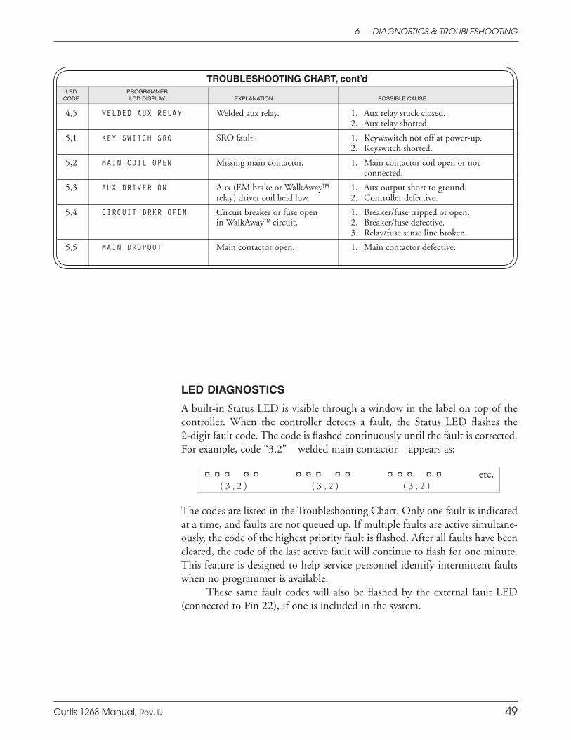
Curtis 1268 Manual, Rev. D 49
4,5 WELDED AUX RELAY Welded aux relay. 1. Aux relay stuck closed. 2. Aux relay shorted.
5,1 KEY SWITCH SRO SRO fault. 1. Keywswitch not off at power-up. 2. Keyswitch shorted.
5,2 MAIN COIL OPEN Missing main contactor. 1. Main contactor coil open or not connected.
5,3 AUX DRIVER ON Aux (EM brake or WalkAway™ 1. Aux output short to ground. relay) driver coil held low. 2. Controller defective.
5,4 CIRCUIT BRKR OPEN Circuit breaker or fuse open 1. Breaker/fuse tripped or open. in WalkAway™ circuit. 2. Breaker/fuse defective. 3. Relay/fuse sense line broken.
5,5 MAIN DROPOUT Main contactor open. 1. Main contactor defective.
TROUBLESHOOTING CHART, cont’d LED PROGRAMMER CODE LCD DISPLAY EXPLANATION POSSIBLE CAUSE
6 — DIAGNOSTICS & TROUBLESHOOTING
LED DIAGNOSTICS
A built-in Status LED is visible through a window in the label on top of the controller. When the controller detects a fault, the Status LED flashes the 2-digit fault code. The code is flashed continuously until the fault is corrected. For example, code “3,2”—welded main contactor—appears as:
¤ ¤ ¤ ¤ ¤ ¤ ¤ ¤ ¤ ¤ ¤ ¤ ¤ ¤ ¤ etc. ( 3 , 2 ) ( 3 , 2 ) ( 3 , 2 )
The codes are listed in the Troubleshooting Chart. Only one fault is indicated at a time, and faults are not queued up. If multiple faults are active simultane-ously, the code of the highest priority fault is flashed. After all faults have been cleared, the code of the last active fault will continue to flash for one minute. This feature is designed to help service personnel identify intermittent faults when no programmer is available.
These same fault codes will also be flashed by the external fault LED (connected to Pin 22), if one is included in the system.
Curtis 1268 Manual, Rev. D 50
MAINTENANCE
There are no user serviceable parts in the Curtis 1268 controller. No attempt should be made to open, repair, or otherwise modify the controller. Doing so may damage the controller and will void the warranty.
It is recommended that the controller be kept clean and dry and that its diagnostics history file be checked and cleared periodically.
CLEANING
Periodically cleaning the controller exterior will help protect it against cor-rosion and possible electrical control problems created by dirt, grime, and chemicals that are part of the operating environment and that normally exist in battery powered systems. When working around any battery powered vehicle, proper safety precautions should be taken. These include, but are not limited to: proper training, wearing eye protection, and avoiding loose clothing and jewelry.
Use the following cleaning procedure for routine maintenance. Never use a high pressure washer to clean the controller.
1. Remove power by disconnecting the battery.
2. Discharge the capacitors in the controller by connecting a load (such as a contactor coil or a horn) across the controller’s B+ and B- terminals.
3. Remove any dirt or corrosion from the power and signal connector areas. The controller should be wiped clean with a moist rag. Dry it before reconnecting the battery.
4. Make sure the connections are tight. Refer to Section 2, page 7, for maximum tightening torque specifications for the battery and motor connections.
FAULT HISTORY
The programmer’s Faults menu can be used to access the controller’s fault his-tory file. The programmer will read out all the faults that the controller has experienced since the last time the fault history file was cleared. The faults may be intermittent faults, faults caused by loose wires, or faults caused by operator errors. Faults such as contactor faults may be the result of loose wires; contactor wiring should be carefully checked. Faults such as HPD or overtemperature may be caused by operator habits or by overloading.
After a problem has been diagnosed and corrected, it is a good idea to clear the fault history file. This allows the controller to accumulate a new file of faults. By checking the new fault history file at a later date, you can readily determine whether the problem was indeed fixed.
7
☞C A U T I O N
7 — MAINTENANCE

Curtis 1268 Manual, Rev. D A-1
APPENDIX A: EMC & ESD DESIGN CONSIDERATIONS
APPENDIX AVEHICLE DESIGN CONSIDERATIONS
REGARDING ELECTROMAGNETIC COMPATIBILITY (EMC)
AND ELECTROSTATIC DISCHARGE (ESD)
ELECTROMAGNETIC COMPATIBILITY (EMC)
Electromagnetic compatibility (EMC) encompasses two areas: emissions and immunity. Emissions are radio frequency (RF) energy generated by a product. This energy has the potential to interfere with communications systems such as radio, television, cellular phones, dispatching, aircraft, etc. Immunity is the ability of a product to operate normally in the presence of RF energy.
EMC is ultimately a system design issue. Part of the EMC performance is designed into or inherent in each component; another part is designed into or inherent in end product characteristics such as shielding, wiring, and layout; and, finally, a portion is a function of the interactions between all these parts. The design techniques presented below can enhance EMC performance in products that use Curtis motor controllers.
Emissions
Signals with high frequency content can produce significant emissions if con-nected to a large enough radiating area (created by long wires spaced far apart). Contactor drivers and the motor drive output from Curtis controllers can contribute to RF emissions. Both types of output are pulse width modulated square waves with fast rise and fall times that are rich in harmonics. (Note: contactor drivers that are not modulated will not contribute to emissions.) The impact of these switching waveforms can be minimized by making the wires from the controller to the contactor or motor as short as possible and by placing the wires near each other (bundle contactor wires with Coil Return; bundle motor wires separately).
For applications requiring very low emissions, the solution may involve enclosing the controller, interconnect wires, contactors, and motor together in one shielded box. Emissions can also couple to battery supply leads and throttle circuit wires outside the box, so ferrite beads near the controller may also be required on these unshielded wires in some applications. It is best to keep the noisy signals as far as possible from sensitive wires.
Immunity
Immunity to radiated electric fields can be improved either by reducing overall circuit sensitivity or by keeping undesired signals away from this circuitry. The controller circuitry itself cannot be made less sensitive, since it must accurately detect and process low level signals from sensors such as the throttle potenti-ometer. Thus immunity is generally achieved by preventing the external RF energy from coupling into sensitive circuitry. This RF energy can get into the controller circuitry via conducted paths and radiated paths.
A-2 Curtis 1268 Manual, Rev. D
APPENDIX A: EMC & ESD DESIGN CONSIDERATIONS
Conducted paths are created by the wires connected to the controller. These wires act as antennas and the amount of RF energy coupled into them is generally proportional to their length. The RF voltages and currents induced in each wire are applied to the controller pin to which the wire is connected. Curtis controllers include bypass capacitors on the printed circuit board’s throttle wires to reduce the impact of this RF energy on the internal circuitry. In some applications, additional filtering in the form of ferrite beads may also be required on various wires to achieve desired performance levels.
Radiated paths are created when the controller circuitry is immersed in an external field. This coupling can be reduced by placing the controller as far as possible from the noise source or by enclosing the controller in a metal box. Some Curtis controllers are enclosed by a heatsink that also provides shielding around the controller circuitry, while others are partially shielded or unshielded. In some applications, the vehicle designer will need to mount the controller within a shielded box on the end product. The box can be constructed of just about any metal, although steel and aluminum are most commonly used.
Most coated plastics do not provide good shielding because the coatings are not true metals, but rather a mixture of small metal particles in a non-con-ductive binder. These relatively isolated particles may appear to be good based on a dc resistance measurement but do not provide adequate electron mobility to yield good shielding effectiveness. Electroless plating of plastic will yield a true metal and can thus be effective as an RF shield, but it is usually more expensive than the coatings.
A contiguous metal enclosure without any holes or seams, known as a Faraday cage, provides the best shielding for the given material and frequency. When a hole or holes are added, RF currents flowing on the outside surface of the shield must take a longer path to get around the hole than if the surface was contiguous. As more “bending” is required of these currents, more energy is coupled to the inside surface, and thus the shielding effectiveness is reduced. The reduction in shielding is a function of the longest linear dimension of a hole rather than the area. This concept is often applied where ventilation is necessary, in which case many small holes are preferable to a few larger ones.
Applying this same concept to seams or joints between adjacent pieces or segments of a shielded enclosure, it is important to minimize the open length of these seams. Seam length is the distance between points where good ohmic contact is made. This contact can be provided by solder, welds, or pressure contact. If pressure contact is used, attention must be paid to the corrosion characteristics of the shield material and any corrosion-resistant processes applied to the base material. If the ohmic contact itself is not continuous, the shielding effectiveness can be maximized by making the joints between adjacent pieces overlapping rather than abutted.
The shielding effectiveness of an enclosure is further reduced when a wire passes through a hole in the enclosure; RF energy on the wire from an external field is re-radiated into the interior of the enclosure. This coupling mechanism can be reduced by filtering the wire where it passes through the shield boundary.

Curtis 1268 Manual, Rev. D A-3
APPENDIX A: EMC & ESD DESIGN CONSIDERATIONS
Given the safety considerations involved in connecting electrical components to the chassis or frame in battery powered vehicles, such filtering will usually consist of a series inductor (or ferrite bead) rather than a shunt capacitor. If a capacitor is used, it must have a voltage rating and leakage characteristics that will allow the end product to meet applicable safety regulations.
The B+ (and B-, if applicable) wires that supply power to a control panel should be bundled with the other control wires to the panel so that all these wires are routed together. If the wires to the control panel are routed separately, a larger loop area is formed. Larger loop areas produce more efficient antennas which will result in decreased immunity performance.
Keep all low power I/O separate from the motor and battery leads. When this is not possible, cross them at right angles.
ELECTROSTATIC DISCHARGE (ESD)
Curtis PMC motor controllers contain ESD-sensitive components, and it is therefore necessary to protect them from ESD (electrostatic discharge) damage. Most of these control lines have protection for moderate ESD events, but must be protected from damage if higher levels exist in a particular application.
ESD immunity is achieved either by providing sufficient distance be-tween conductors and the ESD source so that a discharge will not occur, or by providing an intentional path for the discharge current such that the circuit is isolated from the electric and magnetic fields produced by the discharge. In general the guidelines presented above for increasing radiated immunity will also provide increased ESD immunity.
It is usually easier to prevent the discharge from occurring than to divert the current path. A fundamental technique for ESD prevention is to provide adequately thick insulation between all metal conductors and the outside envi-ronment so that the voltage gradient does not exceed the threshold required for a discharge to occur. If the current diversion approach is used, all exposed metal components must be grounded. The shielded enclosure, if properly grounded, can be used to divert the discharge current; it should be noted that the loca-tion of holes and seams can have a significant impact on ESD suppression. If the enclosure is not grounded, the path of the discharge current becomes more complex and less predictable, especially if holes and seams are involved. Some experimentation may be required to optimize the selection and placement of holes, wires, and grounding paths. Careful attention must be paid to the control panel design so that it can tolerate a static discharge.
MOV, transorbs, or other devices can be placed between B- and offending wires, plates, and touch points if ESD shock cannot be otherwise avoided.

A-4 Curtis 1268 Manual, Rev. D
APPENDIX A: EMC & ESD DESIGN CONSIDERATIONS
B-1
APPENDIX B: PROGRAMMING DEVICES & MENUS
APPENDIX BPROGRAMMING DEVICES & MENUS
Curtis programmers provide programming, diagnostic, and test capabilities for the 1268 controller. The power for operating the programmer is supplied by the host controller via a 4-pin connector. When the programmer powers up, it gathers information from the controller.
Two types of programming devices are available: the 1314 PC Program-ming Station and the 1313 handheld programmer. The Programming Station has the advantage of a large, easily read screen; on the other hand, the hand-held programmer (with its 45×60mm screen) has the advantage of being more portable and hence convenient for making adjustments in the field.
Both programmers are available in User, Service, Dealer, and OEM ver-sions. Each programmer can perform the actions available at its own level and the levels below that—a User-access programmer can operate at only the User level, whereas an OEM programmer has full access.
PC PROGRAMMING STATION (1314)
The Programming Station is an MS-Windows 32-bit application that runs on a standard Windows PC. Instructions for using the Programming Station are included with the software.
HANDHELD PROGRAMMER (1313)
The 1313 handheld programmer is functionally equivalent to the PC Pro-gramming Station; operating instructions are provided in the 1313 manual. This programmer replaces the 1307 and 1311, earlier models with fewer functions.
PROGRAMMER FUNCTIONS
Programmer functions include:
Parameter adjustment — provides access to the individual programmable pa-rameters.
Monitoring — presents real-time values during vehicle operation; these include all inputs and outputs.
Diagnostics and troubleshooting — presents diagnostic information, and also a means to clear the fault history file.
Programming — allows you to save/restore custom parameter settings files and also to update the system software (not available on the 1307 or 1311).
Favorites — allows you to create shortcuts to your frequently-used adjustable parameters and monitor variables (not available on the 1307 or 1311).
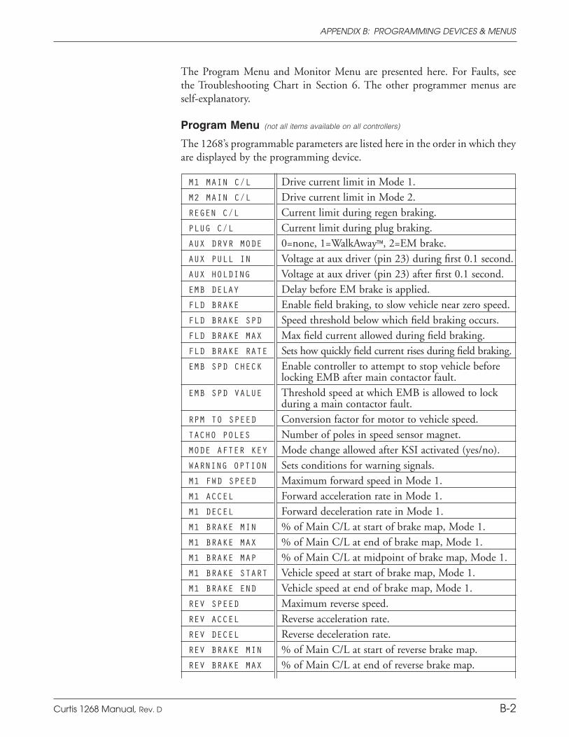
Curtis 1268 Manual, Rev. D A-5
APPENDIX A: EMC & ESD DESIGN CONSIDERATIONS
The Program Menu and Monitor Menu are presented here. For Faults, see the Troubleshooting Chart in Section 6. The other programmer menus are self-explanatory.
Program Menu (not all items available on all controllers)
The 1268’s programmable parameters are listed here in the order in which they are displayed by the programming device.
M1 MAIN C/L Drive current limit in Mode 1.M2 MAIN C/L Drive current limit in Mode 2.REGEN C/L Current limit during regen braking.PLUG C/L Current limit during plug braking.AUX DRVR MODE 0=none, 1=WalkAway™, 2=EM brake.AUX PULL IN Voltage at aux driver (pin 23) during first 0.1 second.AUX HOLDING Voltage at aux driver (pin 23) after first 0.1 second.EMB DELAY Delay before EM brake is applied.FLD BRAKE Enable field braking, to slow vehicle near zero speed.FLD BRAKE SPD Speed threshold below which field braking occurs.FLD BRAKE MAX Max field current allowed during field braking.FLD BRAKE RATE Sets how quickly field current rises during field braking.EMB SPD CHECK Enable controller to attempt to stop vehicle before
locking EMB after main contactor fault.EMB SPD VALUE Threshold speed at which EMB is allowed to lock
during a main contactor fault.RPM TO SPEED Conversion factor for motor to vehicle speed.TACHO POLES Number of poles in speed sensor magnet.MODE AFTER KEY Mode change allowed after KSI activated (yes/no).WARNING OPTION Sets conditions for warning signals.M1 FWD SPEED Maximum forward speed in Mode 1.M1 ACCEL Forward acceleration rate in Mode 1.M1 DECEL Forward deceleration rate in Mode 1.M1 BRAKE MIN % of Main C/L at start of brake map, Mode 1.M1 BRAKE MAX % of Main C/L at end of brake map, Mode 1.M1 BRAKE MAP % of Main C/L at midpoint of brake map, Mode 1.M1 BRAKE START Vehicle speed at start of brake map, Mode 1.M1 BRAKE END Vehicle speed at end of brake map, Mode 1.REV SPEED Maximum reverse speed.REV ACCEL Reverse acceleration rate.REV DECEL Reverse deceleration rate.REV BRAKE MIN % of Main C/L at start of reverse brake map.REV BRAKE MAX % of Main C/L at end of reverse brake map.
APPENDIX B: PROGRAMMING DEVICES & MENUS
B-2
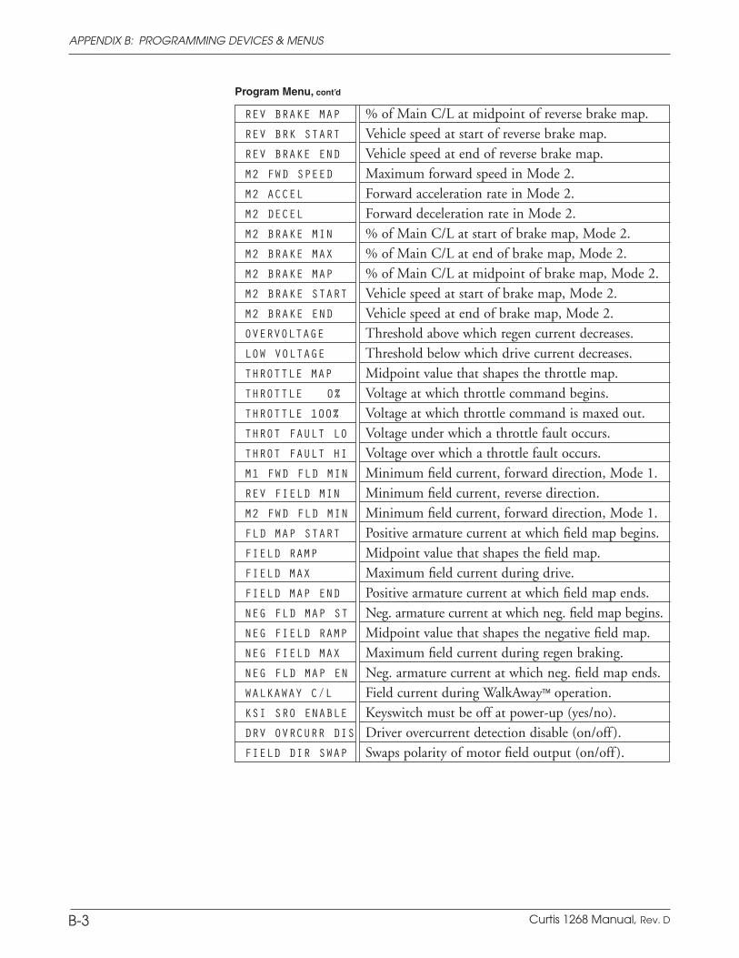
A-6 Curtis 1268 Manual, Rev. D
APPENDIX A: EMC & ESD DESIGN CONSIDERATIONS
REV BRAKE MAP % of Main C/L at midpoint of reverse brake map.REV BRK START Vehicle speed at start of reverse brake map.REV BRAKE END Vehicle speed at end of reverse brake map.M2 FWD SPEED Maximum forward speed in Mode 2.M2 ACCEL Forward acceleration rate in Mode 2.M2 DECEL Forward deceleration rate in Mode 2.M2 BRAKE MIN % of Main C/L at start of brake map, Mode 2.M2 BRAKE MAX % of Main C/L at end of brake map, Mode 2.M2 BRAKE MAP % of Main C/L at midpoint of brake map, Mode 2.M2 BRAKE START Vehicle speed at start of brake map, Mode 2.M2 BRAKE END Vehicle speed at end of brake map, Mode 2.OVERVOLTAGE Threshold above which regen current decreases.LOW VOLTAGE Threshold below which drive current decreases.THROTTLE MAP Midpoint value that shapes the throttle map.THROTTLE 0% Voltage at which throttle command begins.THROTTLE 100% Voltage at which throttle command is maxed out.THROT FAULT LO Voltage under which a throttle fault occurs.THROT FAULT HI Voltage over which a throttle fault occurs.M1 FWD FLD MIN Minimum field current, forward direction, Mode 1.REV FIELD MIN Minimum field current, reverse direction.M2 FWD FLD MIN Minimum field current, forward direction, Mode 1.FLD MAP START Positive armature current at which field map begins.FIELD RAMP Midpoint value that shapes the field map.FIELD MAX Maximum field current during drive.FIELD MAP END Positive armature current at which field map ends.NEG FLD MAP ST Neg. armature current at which neg. field map begins.NEG FIELD RAMP Midpoint value that shapes the negative field map.NEG FIELD MAX Maximum field current during regen braking.NEG FLD MAP EN Neg. armature current at which neg. field map ends.WALKAWAY C/L Field current during WalkAway™ operation.KSI SRO ENABLE Keyswitch must be off at power-up (yes/no).DRV OVRCURR DIS Driver overcurrent detection disable (on/off ).FIELD DIR SWAP Swaps polarity of motor field output (on/off ).
Program Menu, cont’d
APPENDIX B: PROGRAMMING DEVICES & MENUS
B-3
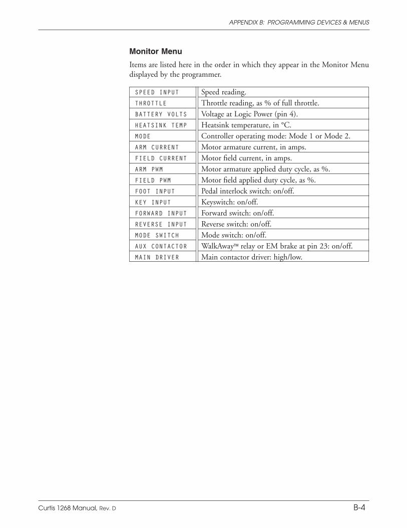
Curtis 1268 Manual, Rev. D A-7
APPENDIX A: EMC & ESD DESIGN CONSIDERATIONS
Monitor Menu
Items are listed here in the order in which they appear in the Monitor Menu displayed by the programmer.
SPEED INPUT Speed reading.THROTTLE Throttle reading, as % of full throttle.BATTERY VOLTS Voltage at Logic Power (pin 4).HEATSINK TEMP Heatsink temperature, in °C.MODE Controller operating mode: Mode 1 or Mode 2.ARM CURRENT Motor armature current, in amps.FIELD CURRENT Motor field current, in amps.ARM PWM Motor armature applied duty cycle, as %.FIELD PWM Motor field applied duty cycle, as %.FOOT INPUT Pedal interlock switch: on/off.KEY INPUT Keyswitch: on/off.FORWARD INPUT Forward switch: on/off.REVERSE INPUT Reverse switch: on/off.MODE SWITCH Mode switch: on/off.AUX CONTACTOR WalkAway™ relay or EM brake at pin 23: on/off.MAIN DRIVER Main contactor driver: high/low.
APPENDIX B: PROGRAMMING DEVICES & MENUS
B-4

A-8 Curtis 1268 Manual, Rev. D
APPENDIX A: EMC & ESD DESIGN CONSIDERATIONS
C-1
Sec. 3 Sec. 5
ACCEL, M1-M2-REV p. 17 6, p. 40
•AUX DRVR MODE p. 28
•AUX PULL IN p. 28
•AUX HOLDING p. 28
BRAKE END, M1-M2-REV p. 22 7, p. 41
BRAKE MAX, M1-M2-REV p. 22 7, p. 41
BRAKE MAP, M1-M2-REV p. 23 7, p. 41
BRAKE MIN, M1-M2-REV p. 22 7, p. 41
BRAKE START, M1-M2-REV p. 22 7, p. 41
DECEL, M1-M2-REV p. 17 7, p. 41
•DRV OVRCUR DIS p. 30
EMB DELAY p. 29 bm, p. 45
•EMB SPD CHECK p. 29
•EMB SPD VALUE p. 29
•FIELD DIR SWAP p. 25
FIELD MAP END p. 25 3, p. 35
FIELD MAX p. 24 3, p. 35
FIELD RAMP p. 25 4, p. 38
FLD BRAKE p. 17 bl, p. 44
FLD BRAKE MAX p. 18 bl, p. 44
FLD BRAKE RATE p. 18 bl, p. 44
FLD BRAKE SPD p. 17 bl, p. 44
FLD MAP START p. 24 4, p. 38
FWD FLD MIN, M1-M2 p. 24 4, p. 38
APPENDIX CPROGRAMMABLE PARAMETER INDEX
The 1268 controller’s programmable parameters are listed below in alphabetical order (by programmer display name), with references provided to the parameter descriptions and to the appropriate Tuning Guide procedures.
The parameters are described individually in Section 3. It is important also to read the tuning procedures in Section 5, as many parameters are highly interdependent with other parameters.
Note: The bulleted parameters (•) are not included in the Tuning Guide; the informa-tion provided in Section 3 is sufficient for adjusting these parameters.
Sec. 3 Sec. 5
FWD SPEED, M1-M2 p. 26 2, p. 35
•KSI SRO ENABLE p. 26
•LOW VOLTAGE p. 26
MAIN C/L, M1-M2 p. 21 3, p. 35
•MODE AFTER KEY p. 26
NEG FIELD MAX p. 24 5, p. 39
NEG FIELD RAMP p. 25 5, p. 39
NEG FLD MAP EN p. 25 5, p. 39
NEG FLD MAP ST p. 24 5, p. 39
•OVERVOLTAGE p. 26
PLUG C/L p. 21 bk, p. 44
REGEN C/L p. 21 5, p. 39
REV FIELD MIN p. 24 4, p. 38
REV SPEED p. 19 2, p. 35
RPM TO SPEED p. 19 2, p. 35
TACHO POLES p. 19 2, p. 35
THROT FAULT LO p. 21 1, p. 33
THROT FAULT HI p. 21 1, p. 33
THROTTLE 0% p. 20 1, p. 33
THROTTLE 100% p. 20 1, p. 33
THROTTLE MAP p. 20 1, p. 33
WALKAWAY C/L p. 21 bk, p. 44
•WARNING OPTION p. 26
APPENDIX C: PARAMETER INDEX
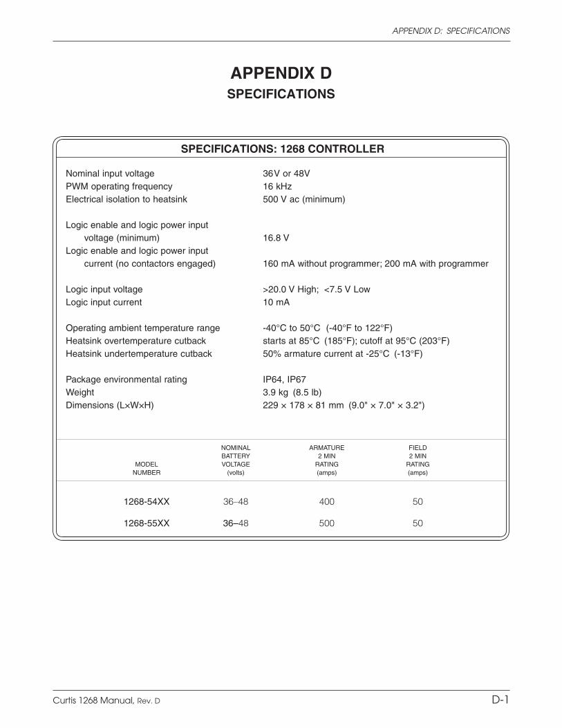
Curtis 1268 Manual, Rev. D A-9
APPENDIX A: EMC & ESD DESIGN CONSIDERATIONSAPPENDIX D: SPECIFICATIONS
D-1
APPENDIX DSPECIFICATIONS
NOMINAL ARMATURE FIELD BATTERY 2 MIN 2 MIN MODEL VOLTAGE RATING RATING NUMBER (volts) (amps) (amps)
1268-54XX 36–48 400 50
1268-55XX 36–48 500 50
SPECIFICATIONS: 1268 CONTROLLER
Nominal input voltage 36 V or 48VPWM operating frequency 16 kHzElectrical isolation to heatsink 500 V ac (minimum)
Logic enable and logic power input voltage (minimum) 16.8 V Logic enable and logic power input current (no contactors engaged) 160 mA without programmer; 200 mA with programmer
Logic input voltage >20.0 V High; <7.5 V Low Logic input current 10 mA
Operating ambient temperature range -40°C to 50°C (-40°F to 122°F)Heatsink overtemperature cutback starts at 85°C (185°F); cutoff at 95°C (203°F)Heatsink undertemperature cutback 50% armature current at -25°C (-13°F)
Package environmental rating IP64, IP67Weight 3.9 kg (8.5 lb)Dimensions (L×W×H) 229 × 178 × 81 mm (9.0" × 7.0" × 3.2")