Manual Knee Lock ESK+ 239440B with Single Bolt Alignment
4
938230/2-0120 45mm Max. flexion 115 o Manual Knee Lock ESK+ 239440B with Single Bolt Alignment ± 6mm 100 kg 125 kg Blatchford Products Limited Unit D Antura, Kingsland Business Park, Basingstoke,RG24 8PZ, UNITED KINGDOM Tel: +44 (0) 1256 316600, Fax: +44 (0) 1256 316710 Email: [email protected], www.blatchford.co.uk
Transcript of Manual Knee Lock ESK+ 239440B with Single Bolt Alignment

938230/2-0120
45mmMax. flexion
115o
Manual Knee Lock ESK+ 239440Bwith Single Bolt Al ignment
± 6mm
100 kg
125 kg
Blatchford Products LimitedUnit D Antura, Kingsland Business Park,Basingstoke,RG24 8PZ, UNITED KINGDOMTel: +44 (0) 1256 316600, Fax: +44 (0) 1256 316710Email: [email protected], www.blatchford.co.uk
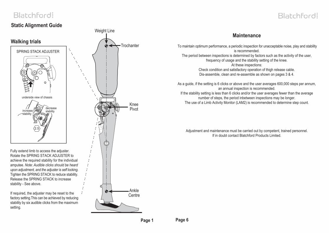
Fully extend limb to access the adjuster.Rotate the SPRING STACK ADJUSTER toachieve the required stability for the individualamputee. Note: Audible clicks should be heardupon adjustment, and the adjuster is self locking.Tighten the SPRING STACK to reduce stability.Release the SPRING STACK to increasestability - See above.
If required, the adjuster may be reset to thefactory setting.This can be achieved by reducingstability by six audible clicks from the maximumsetting.
Static Alignment Guide
Walking trials
2.5
Page 1
KneePivot
AnkleCentre
Weight Line
Page 6
underside view of chassis
Maintenance
To maintain optimum performance, a periodic inspection for unacceptable noise, play and stabilityis recommended.
The period between inspections is determined by factors such as the activity of the user,frequency of usage and the stability setting of the knee.
At these inspections:Check condition and satisfactory operation of thigh release cable.Dis-assemble, clean and re-assemble as shown on pages 3 & 4.
As a guide, if the setting is 6 clicks or above and the user averages 600,000 steps per annum,an annual inspection is recommended.
If the stability setting is less than 6 clicks and/or the user averages fewer than the averagenumber of steps, the period inbetween inspections may be longer.
The use of a Limb Activity Monitor (LAM2) is recommended to determine step count.
Adjustment and maintenance must be carried out by competent, trained personnel.If in doubt contact Blatchford Products Limited.
Trochanter
decreasestabilityincrease
stability
SPRING STACK ADJUSTER

MKL Adjustment
2
6
2.5
4
2.5
Cable fitting using Thigh Release Kit (239640) - available separately.
Page 5 Page 2
1
3
6 A/F
5
6 A/F
Loosen trunnionclamp screw. Turnpiston rod to revealthread and apply
Loctite 242 and re-assemble.
Back off frontstop to clear
Adjust pistonrod until thePatella locks
into placeover front of
chassiswithout rock.
Apply a slightextension load.
Insert a 5mm widepiece of paper
between front stopand buffer.Adjust
front stop untilpaper can be
removed underslight resistance
Any final adjustment required to alleviaterock should be by adjustment of the
front stop.
Check operation of lock again,immediately prior to fitting to wearer.
(these adjustments are carried out at the factory, however, should subsequent adjustmentbe required, these steps should be followed)
Withdraw trunnion clamp screwand apply LOCTITE 222 to
thread, re-assemble and tighten.
*UNDER NOCIRCUMSTANCES MUST THEPISTON ROD WITNESS LINE
BE VISIBLE BELOW THETRUNNION.
1. Lay cable against socket and locate sleeve inside counterbore in front of chassis (makeallowance for changes in alignment).2. Feed inner cable through hole in chassis.3. Feed cable through cable clamp and secure, clamping onto tinned area at end of cable.4. When fitting cable to thigh release, ensure release lever operates against the patella to unlockknee as required.5. Refer to fitting instructions supplied with Thigh Release Kit.
Patella and shin components not shown for clarity.
knee locked
1.5
knee unlocked
cable clamp
cable
cable sleeve
release lever
2.5
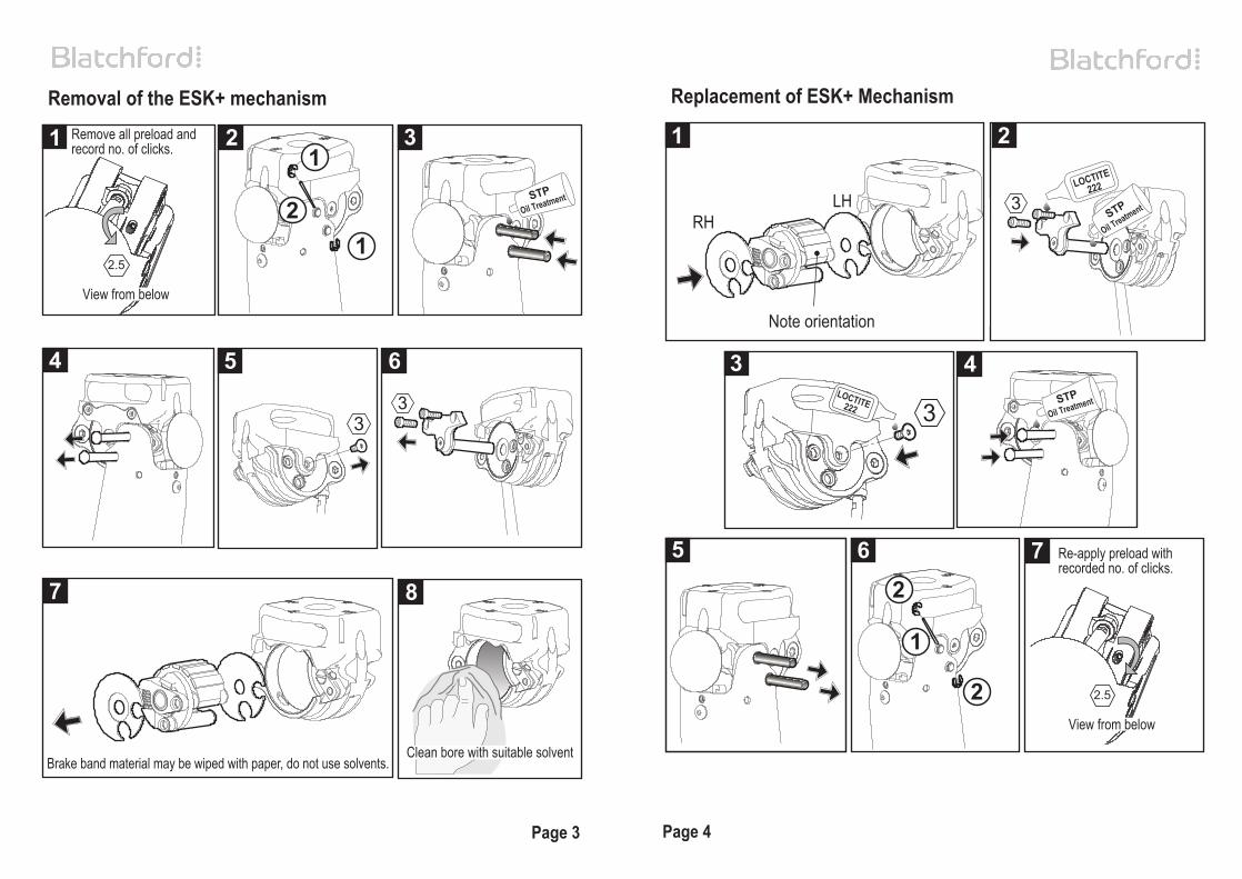
Removal of the ESK+ mechanism Replacement of ESK+ Mechanism
1 2 3
4 5 6
2.5
3 4
5 6 7
1 2
2.5
Brake band material may be wiped with paper, do not use solvents.
Page 3 Page 4
RHLH
3
3LOCTITE
222
STP
Oil Treatment
3
STPOil Treatment
7 8
Remove all preload andrecord no. of clicks.
View from below
Clean bore with suitable solvent
Note orientation
Re-apply preload withrecorded no. of clicks.
View from below
LOCTITE222STP
Oil Treatment
2
1
2
3
12
1