
Manual - i-techno.ru 314st-dpm... · Manual VIPA System 300S SPEED7 User considerations ... •...
192
Manual VIPA System 300S SPEED7 - CPU 314-6CF02 Order No.: VIPA HB140E_CPU Reference: RE_314-6CF02 Rev. 09/11 This manual is part of the documentation package with order number VIPA HB140_CPU and relevant for: Product Order number as of state: CPU-HW CPU-FW DPM-FW CPU 314ST/DPM VIPA 314-6CF02 01 V343 V312
Transcript of Manual - i-techno.ru 314st-dpm... · Manual VIPA System 300S SPEED7 User considerations ... •...

Manual
VIPA System 300S SPEED7 - CPU
314-6CF02
Order No.: VIPA HB140E_CPU Reference: RE_314-6CF02
Rev. 09/11
This manual is part of the documentation package with order number VIPA HB140_CPU and relevant for: Product Order number as of state: CPU-HW CPU-FW DPM-FW CPU 314ST/DPM VIPA 314-6CF02 01 V343 V312


Manual VIPA System 300S SPEED7 About this manual
Subject to change to cater for technical progress.
The information contained in this manual is supplied without warranties. The information is subject to change without notice. © Copyright 2009 VIPA, Gesellschaft für Visualisierung und Prozess-
automatisierung mbH Ohmstraße 4, D-91074 Herzogenaurach,
Tel.: +49 (91 32) 744 -0 Fax.: +49 (91 32) 744-1864 EMail: [email protected] http://www.vipa.de Hotline: +49 (91 32) 744-1150 All rights reserved
The contents of this manual were verified with respect to the hard- and software. However, we assume no responsibility for any discrepancies or errors. The information in this manual is verified on a regular basis and any required corrections will be included in subsequent editions. Suggestions for improvement are always welcome.
VIPA and System 300V are registered trademarks of VIPA Gesellschaft für Visualisierung und Prozessautomatisierung mbH. SPEED7 is a registered trademark of profichip GmbH. SIMATIC, STEP and S7-300 are registered trademarks of Siemens AG. Microsoft Windows and Windows Vista are registered trademarks of Microsoft Cooperation. Any other trademarks referred to in the text are the trademarks of the respective owner and we acknowledge their registration.
Disclaimer of liability
Trademarks

About this manual Manual VIPA System 300S SPEED7
Subject to change to cater for technical progress.
About this manual
This manual describes the System 300S SPEED7 CPU 314ST/DPM from VIPA. Here you may find every information for commissioning and operation. Chapter 1: Principles This Basics contain hints for the usage and information about the project engineering of a SPEED7 system from VIPA. General information about the System 300S like dimensions and environment conditions will also be found. Chapter 2: Assembly and installation guidelines In this chapter you will find all information, required for the installation and the cabling of a process control with the components of a CPU 314ST/DPM in the System 300. Chapter 3: Hardware description Here the hardware components of the CPU 314ST/DPM are described. The technical data are at the end of the chapter. Chapter 4: Deployment CPU 314ST/DPM This chapter describes the employment of a CPU 314ST/DPM with SPEED7 technology in the System 300. The description refers directly to the CPU and to the employment in connection with peripheral modules that are mounted on a profile rail together with the CPU at the standard bus. Chapter 5: Deployment PtP communication This chapter contains all information necessary for the employment of the in-/output periphery of the CPU 314ST/DPM. It describes functionality, project engineering and diagnostic of the analog and digital part. Chapter 6: Deployment I/O periphery Content of this chapter is the employment of the RS485 slot for serial PtP communication. Here you’ll find all information about the protocols, the activation and project engineering of the interface which are necessary for the serial communication using the RS485 interface. Chapter 7: Deployment Profibus communication Content of this chapter is the deployment of the CPU 314ST/DPM with Profibus. After a short overview the project engineering and parameterization of a CPU 314ST/DPM with integrated Profibus-Part from VIPA is shown. Further you get information about usage as DP master and DP slave of the Profibus part. The chapter is ended with notes to commissioning and start-up. Chapter 8: WinPLC7 In this chapter the programming and simulation software WinPLC7 from VIPA is presented. WinPLC7 is suited for every with Siemens STEP®7 programmable PLC. Besides the system presentation and installation here the basics for using the software is explained with a sample project. More information concerning the usage of WinPLC7 may be found in the online help respectively in the online documentation of WinPLC7.
Overview

Manual VIPA System 300S SPEED7 Contents
HB140E - CPU - RE_314-6CF02 - Rev. 09/11 i
Contents
User considerations ................................................................................. 1 Safety information.................................................................................... 2 Chapter 1 Basics .............................................................................. 1-1
Safety Information for Users................................................................. 1-2 General description of the System 300................................................. 1-3 Operating structure of a CPU............................................................... 1-4 CPU 314ST/DPM ................................................................................. 1-7
Chapter 2 Assembly and installation guidelines............................ 2-1 Overview .............................................................................................. 2-2 Installation dimensions ......................................................................... 2-3 Assembly Standard-Bus....................................................................... 2-4 Assembly SPEED-Bus ......................................................................... 2-5 Cabling................................................................................................. 2-8 Installation guidelines ......................................................................... 2-11
Chapter 3 Hardware description ..................................................... 3-1 Properties............................................................................................. 3-2 Structure .............................................................................................. 3-3 Components......................................................................................... 3-4 In-/Output range................................................................................... 3-8 Technical Data ................................................................................... 3-11
Chapter 4 Deployment CPU 314ST/DPM......................................... 4-1 Assembly Standard-Bus....................................................................... 4-2 Assembly SPEED-Bus ......................................................................... 4-3 Start-up behavior.................................................................................. 4-6 Addressing ........................................................................................... 4-7 Initialization Ethernet PG/OP channel ................................................ 4-11 Access to the internal Web page........................................................ 4-14 Project engineering ............................................................................ 4-16 Setting standard CPU parameters...................................................... 4-22 Setting VIPA specific CPU parameters............................................... 4-29 Parameterization of modules.............................................................. 4-33 Project transfer................................................................................... 4-34 Operating modes................................................................................ 4-38 Overall reset....................................................................................... 4-41 Firmware update ................................................................................ 4-43 Factory reset ...................................................................................... 4-46 Memory extension with MCC.............................................................. 4-47 Extended know-how protection........................................................... 4-48 MMC-Cmd - Auto commands ............................................................. 4-50 VIPA specific diagnostic entries ......................................................... 4-52 Using test functions for control and monitoring of variables................ 4-56

Contents Manual VIPA System 300S SPEED7
ii HB140E - CPU - RE_314-6CF02 - Rev. 09/11
Chapter 5 Deployment I/O periphery............................................... 5-1 Overview .............................................................................................. 5-2 In-/Output range................................................................................... 5-3 Analog part........................................................................................... 5-5 Analog Part - Parameterization ............................................................ 5-9 Analog part - Diagnostic functions...................................................... 5-13 Digital part .......................................................................................... 5-16 Counter - Fast introduction................................................................. 5-18 Counter - Parameterization ................................................................ 5-21 Counter - Functions............................................................................ 5-26 Counter - Additional functions ............................................................ 5-32 Counter - Diagnostic and interrupt...................................................... 5-39
Chapter 6 Deployment PtP communication ................................... 6-1 Fast introduction................................................................................... 6-2 Protocols and procedures .................................................................... 6-3 Deployment of RS485 interface for PtP................................................ 6-7 Principle of the data transfer ................................................................ 6-9 Parameterization ................................................................................ 6-10 Communication .................................................................................. 6-13
Chapter 7 Deployment Profibus communication........................... 7-1 Overview .............................................................................................. 7-2 Project engineering CPU with integrated Profibus master .................... 7-3 Deployment as Profibus DP slave ........................................................ 7-5 Profibus installation guidelines ............................................................. 7-7 Commissioning and Start-up behavior................................................ 7-10
Chapter 8 WinPLC7 .......................................................................... 8-1 System presentation............................................................................. 8-2 Installation............................................................................................ 8-3 Example project engineering ................................................................ 8-4
Appendix ................................................................................................A-1 Index ....................................................................................................A-1

Manual VIPA System 300S SPEED7 User considerations
HB140E - CPU - RE_314-6CF02 - Rev. 09/11 1
User considerations
This manual describes the System 300S SPEED7 CPU 314ST/DPM from VIPA. It contains a description of the construction, project implementation and usage.
The manual is targeted at users who have a background in automation technology.
The manual consists of chapters. Every chapter provides a self-contained description of a specific topic.
The following guides are available in the manual: • an overall table of contents at the beginning of the manual • an overview of the topics for every chapter • an index at the end of the manual.
The manual is available in: • printed form, on paper • in electronic form as PDF-file (Adobe Acrobat Reader)
Important passages in the text are highlighted by following icons and headings:
Danger! Immediate or likely danger. Personal injury is possible.
Attention! Damages to property is likely if these warnings are not heeded.
Note! Supplementary information and useful tips.
Objective and contents
Target audience
Structure of the manual
Guide to the document
Availability
Icons Headings
Safety information Manual VIPA System 300S SPEED7
2 HB140E - CPU - RE_314-6CF02 - Rev. 09/11
Safety information
The SPEED7 is constructed and produced for: • all VIPA System 300 components • communication and process control • general control and automation applications • industrial applications • operation within the environmental conditions specified in the technical
data • installation into a cubicle
Danger! This device is not certified for applications in • in explosive environments (EX-zone)
The manual must be available to all personnel in the • project design department • installation department • commissioning • operation
The following conditions must be met before using or commissioning the components described in this manual: • Modification to the process control system should only be carried out
when the system has been disconnected from power! • Installation and modifications only by properly trained personnel • The national rules and regulations of the respective country must be
satisfied (installation, safety, EMC ...)
National rules and regulations apply to the disposal of the unit!
Applications conforming with specifications
Documentation
Disposal

Manual VIPA System 300S SPEED7 Chapter 1 Basics
HB140E - CPU - RE_314-6CF02 - Rev. 09/11 1-1
Chapter 1 Basics
This Basics contain hints for the usage and information about the project engineering of a SPEED7 system from VIPA. General information about the System 300S like dimensions and environment conditions will also be found.
Topic Page Chapter 1 Basics .............................................................................. 1-1
Safety Information for Users................................................................. 1-2 General description of the System 300................................................. 1-3 Operating structure of a CPU ............................................................... 1-4 CPU 314ST/DPM ................................................................................. 1-7
Overview
Content

Chapter 1 Basics Manual VIPA System 300S SPEED7
1-2 HB140E - CPU - RE_314-6CF02 - Rev. 09/11
Safety Information for Users
VIPA modules make use of highly integrated components in MOS-Technology. These components are extremely sensitive to over-voltages that can occur during electrostatic discharges. The following symbol is attached to modules that can be destroyed by electrostatic discharges.
The Symbol is located on the module, the module rack or on packing material and it indicates the presence of electrostatic sensitive equipment. It is possible that electrostatic sensitive equipment is destroyed by energies and voltages that are far less than the human threshold of perception. These voltages can occur where persons do not discharge themselves before handling electrostatic sensitive modules and they can damage components thereby, causing the module to become inoperable or unusable. Modules that have been damaged by electrostatic discharges can fail after a temperature change, mechanical shock or changes in the electrical load. Only the consequent implementation of protection devices and meticulous attention to the applicable rules and regulations for handling the respective equipment can prevent failures of electrostatic sensitive modules.
Modules must be shipped in the original packing material.
When you are conducting measurements on electrostatic sensitive modules you should take the following precautions: • Floating instruments must be discharged before use. • Instruments must be grounded. Modifying electrostatic sensitive modules you should only use soldering irons with grounded tips.
Attention! Personnel and instruments should be grounded when working on electrostatic sensitive modules.
Handling of electrostatic sensitive modules
Shipping of electrostatic sensitive modules
Measurements and alterations on electrostatic sensitive modules

Manual VIPA System 300S SPEED7 Chapter 1 Basics
HB140E - CPU - RE_314-6CF02 - Rev. 09/11 1-3
General description of the System 300
The System 300 is a modular automation system for middle and high performance needs, that you can use either central or decentral. The single modules are directly clipped to the profile rail and are connected together with the help of bus clips at the backside. The CPUs of the System 300 are instruction set compatible to S7-300 from Siemens.
VIPA differentiates between System 300V and System 300S. • System 300V
The System 300V allows you to resolve automation tasks central and decentral. The single modules of the System 300V from VIPA are similar in construction to Siemens. Due to the compatible backplane bus, the modules from VIPA and Siemens can be mixed.
• System 300S The System 300S extends the central area with high-speed CPUs that have the integrated SPEED7 chip. Additionally some CPU's have got a parallel SPEED-Bus that allows the modular connection of fast peripheral modules like IOs or bus master.
VIPA System 300
decentral
Periphery
Profibusfor STEP®7 from Siemens
PLC-CPUCANwith SPEED7
for STEP®7 from Siemens
PLC-CPUwith SPEED7 and SPEED-Bus
for STEP®7 from Siemens
PLC-CPU
SPEED-Bus periphery
System 300V System 300S
central central
Profibus DP master / INTERBUS masterCANopen master/slave / CP / Dig. I/O, Anal. I/O
Dig. IN / Dig. OUT / Anal. IN / Anal. OUT / CP
This manual describes a CPU from the System 300S with integrated SPEED7 technology and SPEED-Bus to connect the SPEED-Bus peripheral modules from VIPA. The description of the System 300V CPU 31x and the concerning peripheral modules like digital and analog in-/output modules, power supplies and bus coupler is to find in the HB 130.
The System 300
System 300V System 300S
Manual overview

Chapter 1 Basics Manual VIPA System 300S SPEED7
1-4 HB140E - CPU - RE_314-6CF02 - Rev. 09/11
Operating structure of a CPU
The CPU contains a standard processor with internal program memory. In combination with integrated SPEED7 technology and SPEED-Bus, the unit provides a powerful solution for process automation applications within the System 300S family. A CPU supports the following modes of operation: • cyclic operation • timer processing • alarm controlled operation • priority based processing
Cyclic processing represents the major portion of all the processes that are executed in the CPU. Identical sequences of operations are repeated in a never-ending cycle.
Where a process requires control signals at constant intervals you can initiate certain operations based upon a timer, e.g. not critical monitoring functions at one-second intervals.
If a process signal requires a quick response you would allocate this signal to an alarm controlled procedure. An alarm can activate a procedure in your program.
The above processes are handled by the CPU in accordance with their priority. Since a timer or an alarm event requires a quick reaction, the CPU will interrupt the cyclic processing when these high-priority events occur to react to the event. Cyclic processing will resume, once the reaction has been processed. This means that cyclic processing has the lowest priority.
General
Cyclic processing
Timer processing
Alarm controlled processing
Priority based processing

Manual VIPA System 300S SPEED7 Chapter 1 Basics
HB140E - CPU - RE_314-6CF02 - Rev. 09/11 1-5
The program that is present in every CPU is divided as follows: • System routine • User application
The system routine organizes all those functions and procedures of the CPU that are not related to a specific control application.
This consists of all the functions that are required for the processing of a specific control application. The operating modules provide the interfaces to the system routines.
The following series of operands is available for programming the CPU: • Process image and periphery • Bit memory • Timers and counters • Data blocks
The user application can quickly access the process image of the inputs and outputs PAA/PAE. You may manipulate the following types of data: • individual Bits • Bytes • Words • Double words You may also gain direct access to peripheral modules via the bus from user application. The following types of data are available: • Bytes • Words • Blocks
Applications
System routine
User application
Operands
Process image and periphery

Chapter 1 Basics Manual VIPA System 300S SPEED7
1-6 HB140E - CPU - RE_314-6CF02 - Rev. 09/11
The bit memory is an area of memory that is accessible by means of certain operations. Bit memory is intended to store frequently used working data. You may access the following types of data: • individual Bits • Bytes • Words • Double words
In your program you may load cells of the timer with a value between 10ms and 9990s. As soon as the user application executes a start-operation, the value of this timer is decremented by the interval that you have specified until it reaches zero. You may load counter cells with an initial value (max. 999) and increment or decrement these when required.
A data block contains constants or variables in the form of bytes, words or double words. You may always access the current data block by means of operands. You may access the following types of data: • individual Bits • Bytes • Words • Double words
Bit Memory
Timers and counters
Data Blocks

Manual VIPA System 300S SPEED7 Chapter 1 Basics
HB140E - CPU - RE_314-6CF02 - Rev. 09/11 1-7
CPU 314ST/DPM
The CPU 314ST/DPM bases upon the SPEED7 technology. This supports the CPU at programming and communication by means of co-processors that causes a power improvement for highest needs. The SPEED7-CPU is provided with a parallel SPEED-Bus that enables the additional connection of up to 10 modules from the SPEED-Bus periphery. While the standard peripheral modules are plugged-in at the right side of the CPU, the SPEED bus peripheral modules are connected via a SPEED-Bus bus connector at the left side of the CPU.
Standard bus (serial)SPEED-Bus (parallel)
The SPEED7 CPUs from VIPA are instruction compatible to the programming language STEP®7 from Siemens and may be programmed via WinPLC7 from VIPA or via the Siemens SIMATIC Manager. Here the instruction set of the S7-400 from Siemens is used. Modules and CPUs of the System 300 from VIPA and Siemens may be used at the "Standard" bus as a mixed configuration. The user application is stored in the battery buffered RAM or on an additionally pluggable MMC storage module. The CPU is configured as CPU 318-2 (6ES7 318-2AJ00-0AB0/V3.0) from Siemens.
Overview

Chapter 1 Basics Manual VIPA System 300S SPEED7
1-8 HB140E - CPU - RE_314-6CF02 - Rev. 09/11
PC
CPU
DP master
MMC
DP
MMC
RNSTMR
Tip3Sec.
wld file
System data
RAM
MPI Adapter
PG/OPPower ON
RN
CPU
TP
overall reset
firmware
FlashFirmw.Proj.
RAM
Ethernet
MPI
Proj.
Proj./Firmw.
RS232
DP Adapter
RAM FlashFirmw.Proj.
Web-Browser
WinPLC7 from VIPASIMATIC Manager from Siemens
RJ45
Web
Note! Please do always use the CPU 318-2 (6ES7 318-2AJ00-0AB0/V3.0) from Siemens of the hardware catalog to project a SPEED7-CPU from VIPA. For the project engineering, a thorough knowledge of the Siemens SIMATIC Manager and the hardware configurator from Siemens is required!
The CPU has a work memory of about 512kbyte. During program run the work memory is divided into 50% for program and 50% for data. There is the possibility to expand the work memory to max. 2Mbyte. The size of the load memory is fixed at 2Mbyte.
Access options
Memory management

Manual VIPA System 300S SPEED7 Chapter 1 Basics
HB140E - CPU - RE_314-6CF02 - Rev. 09/11 1-9
The SPEED-Bus is a 32bit parallel bus developed from VIPA with a maximum data rate of 40Mbyte/s. Via the SPEED-Bus you may connect up to 10 SPEED-Bus modules to your CPU 314ST/DPM. In opposite to the "standard" backplane bus where the modules are plugged-in at the right side of the CPU by means of single bus connectors, the modules at the SPEED-Bus are plugged-in at the left side of the CPU via a special SPEED-Bus rail. VIPA delivers profile rails with integrated SPEED-Bus for 2, 6, or 10 SPEED-Bus peripheral modules with different lengths. The CPU has an integrated Profibus DP master. Via the DP master with a data range of 1kbyte for in- and output you may address up to 125 DP slaves. The project engineering takes place in WinPLC7 from VIPA or in the hardware configurator from Siemens. The CPU has an Ethernet interface for PG/OP communication. Via the "PLC" functions you may directly access the Ethernet PG/OP channel and program res. remote control your CPU. A max. of 4 PG/OP connections is available. You may also access the CPU with a visualization software via these connections. • Wiring by means of spring pressure connections (CageClamps) at the
front connector • Core cross-section 0.08...2.5mm2 • Total isolation of the wiring at module change • Potential separation of all modules to the backplane bus • ESD/Burst acc. IEC 61000-4-2/IEC 61000-4-4 (up to level 3) • Shock resistance acc. IEC 60068-2-6 / IEC 60068-2-27 (1G/12G) • Operating temperature: 0 ... +60°C • Storage temperature: -25 ... +70°C • Relative humidity: 5 ... 95% without condensation • Ventilation by means of a fan is not required • Dimensions of the basic enclosure:
2tier width: (WxHxD) in mm: 80x125x120 The CPU comes with an integrated power supply. The power supply is to be supplied with DC 24V. By means of the supply voltage, the internal electronic is supplied as well as the connected modules via backplane bus. The power supply is protected against inverse polarity and overcurrent. Please regard that the integrated power supply may supply the backplane bus (SPEED-Bus and Standard bus) with a sum of 5A. Each SPEED-Bus rail has a slot for an external power supply. This allows you to raise the maximum current at the back plane bus for 6A.
SPEED-Bus
Integrated Profibus DP master
Integrated Ethernet PG/OP channel
Operation Security
Environmental conditions
Dimensions/ Weight
Integrated power supply

Chapter 1 Basics Manual VIPA System 300S SPEED7
1-10 HB140E - CPU - RE_314-6CF02 - Rev. 09/11

Manual VIPA System 300S SPEED7 Chapter 2 Assembly and installation guidelines
HB140E - CPU - RE_314-6CF02 - Rev. 09/11 2-1
Chapter 2 Assembly and installation guidelines
In this chapter you will find all information, required for the installation and the cabling of a process control with the components of a CPU 314ST/DPM in the System 300.
Topic Page Chapter 2 Assembly and installation guidelines............................ 2-1
Overview .............................................................................................. 2-2 Installation dimensions ......................................................................... 2-3 Assembly Standard-Bus....................................................................... 2-4 Assembly SPEED-Bus ......................................................................... 2-5 Cabling................................................................................................. 2-8 Installation guidelines ......................................................................... 2-11
Overview
Content

Chapter 2 Assembly and installation guidelines Manual VIPA System 300S SPEED7
2-2 HB140E - CPU - RE_314-6CF02 - Rev. 09/11
Overview
The CPU 314ST/DPM is provided with a parallel SPEED-Bus that enables the additional connection of up to 10 modules from the SPEED-Bus periphery. While the standard peripheral modules are plugged-in at the right side of the CPU, the SPEED-Bus peripheral modules are connected via a SPEED-Bus bus connector at the left side of the CPU. VIPA delivers profile rails with integrated SPEED-Bus for 2, 6 or 10 SPEED-Bus peripheral modules with different lengths.
Standard-Bus (serial)SPEED-Bus (parallel)
The single modules are directly installed on a profile rail and connected via the backplane bus coupler. Before installing the modules you have to clip the backplane bus coupler to the module from the backside. The backplane bus couplers are included in the delivery of the peripheral modules. With SPEED-Bus the bus connection happens via a SPEED-Bus rail integrated in the profile rail at the left side of the CPU. Due to the parallel SPEED-Bus not all slots must be occupied in sequence. At slot (SLOT 1 DCDC) you may plug either a SPEED-Bus module or an additional power supply. You may assemble the System 300 horizontally, vertically or lying.
SLOT1DCDC
CPUSLOT2
SLO
T1D
CD
C
CPU
SLO
T2
horizontal assembly
lying assembly
verticalassembly
Please regard the allowed environment tempera-tures:
• horizontal assembly: from 0 to 60°C • vertical assembly: from 0 to 40°C • lying assembly: from 0 to 40°C
General
Serial Standard bus
Parallel SPEED-Bus
SLOT 1 for additional power supply
Assembly possibilities

Manual VIPA System 300S SPEED7 Chapter 2 Assembly and installation guidelines
HB140E - CPU - RE_314-6CF02 - Rev. 09/11 2-3
Installation dimensions
2tier width (WxHxD) in mm: 80 x 125 x 120
65m
m 4
0mm
122
mm
125
mm
125mm
120mm
175mm
Dimensions Basic enclosure
Dimensions
Installation dimensions

Chapter 2 Assembly and installation guidelines Manual VIPA System 300S SPEED7
2-4 HB140E - CPU - RE_314-6CF02 - Rev. 09/11
Assembly Standard-Bus
SLOT1DCDC
SLOT2
horizontal assembly
lying assembly
verticalassembly
Assembly possibilities Please regard the allowed environment temperatures:
• horizontal assembly: from 0 to 60°C • vertical assembly: from 0 to 40°C • lying assembly: from 0 to 40°C
If you do not deploy SPEED-Bus modules, the assembly happens with the following approach: • Bolt the profile rail with the background (screw size: M6),
so that you still have minimum 65mm space above and 40mm below the profile rail.
• If the background is a grounded metal or device plate, please look for a low-impedance connection between profile rail and background.
• Connect the profile rail with the protected earth conductor. For this purpose there is a bolt with M6-thread.
• The minimum cross-section of the cable to the protected earth conductor has to be 10mm2.
• Stick the power supply to the profile rail and pull it to the left side to the grounding bolt of the profile rail.
• Fix the power supply by screwing. • Take a backplane bus connector and click it at the CPU
from the backside like shown in the picture. • Stick the CPU to the profile rail right from the power supply
and pull it to the power supply.
• Click the CPU downwards and bolt it like shown. • Repeat this procedure with the peripheral modules, by
clicking a backplane bus connector, stick the module right from the modules you've already fixed, click it downwards and connect it with the backplane bus connector of the last module and bolt it.
Danger! • The power supplies must be released before installation and repair
tasks, i.e. before handling with the power supply or with the cabling you must disconnect current/voltage (pull plug, at fixed connection switch off the concerning fuse)!
• Installation and modifications only by properly trained personnel!

Manual VIPA System 300S SPEED7 Chapter 2 Assembly and installation guidelines
HB140E - CPU - RE_314-6CF02 - Rev. 09/11 2-5
Assembly SPEED-Bus
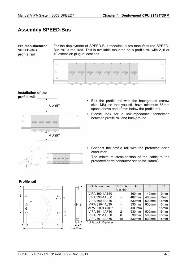
For the deployment of SPEED-Bus modules, a pre-manufactured SPEED-Bus rail is required. This is available mounted on a profile rail with 2, 6 or 10 extension plug-in locations.
SLOT1DCDC
CPUSLOT2SLOT3SLOT4SLOT5SLOT6
SLOT1DCDC
CPUSLOT2
65mm
40mm
SLOT1DCDC
CPUSLOT2
• Bolt the profile rail with the background (screw size: M6), so that you still have minimum 65mm space above and 40mm below the profile rail.
• Please look for a low-impedance connection between profile rail and background
• Connect the profile rail with the protected earth
conductor. The minimum cross-section of the cable to the
protected earth conductor has to be 10mm2.
Profile rail
G
122
Order number SPEED-
Bus slotA B C
VIPA 390-1AB60 - 160mm 140mm 10mmVIPA 390-1AE80 - 482mm 466mm 8.3mmVIPA 390-1AF30 - 530mm 500mm 15mmVIPA 390-1AJ30 - 830mm 800mm 15mm
VIPA 390-9BC00* - 2000mm - 15mmVIPA 391-1AF10 2 530mm 500mm 15mmVIPA 391-1AF30 6 530mm 500mm 15mmVIPA 391-1AF50 10 530mm 500mm 15mm
* Unit pack 10 pieces
Pre-manufactured SPEED-Bus profile rail
Installation of the profile rail

Chapter 2 Assembly and installation guidelines Manual VIPA System 300S SPEED7
2-6 HB140E - CPU - RE_314-6CF02 - Rev. 09/11
1 2 3
• Dismantle the according protection flaps of the SPEED-Bus plug-in locations with a screw driver (open and pull down). For the SPEED-Bus is a parallel bus, not all SPEED-Bus plug-in locations must be used in series. Leave the protection flap installed at an unused SPEED-Bus plug-in location.
• At deployment of a DC 24V power supply, install it at the shown position at the profile rail at the left side of the SPEED-Bus and push it to the left to the isolation bolt of the profile rail.
• Fix the power supply by screwing.
SLOT1DCDC
CPUSLOT2
• To connect the SPEED-Bus modules, plug it between the triangular positioning helps to a plug-in location marked with "SLOT ..." and pull it down.
• Only the "SLOT1 DCDC" allows you to plug-in either a SPEED-Bus module or an additional power supply.
• Fix the modules by screwing.
SLOT1DCDC
CPUSLOT2
SLOT2
• To deploy the SPEED7-CPU exclusively at the SPEED-Bus, plug it between the triangular positioning helps to the plug-in location marked with "CPU SPEED7" and pull it down.
• Fix the CPU by screwing.
Installation SPEED-Bus-Module
Installation CPU without Standard-Bus-Modules

Manual VIPA System 300S SPEED7 Chapter 2 Assembly and installation guidelines
HB140E - CPU - RE_314-6CF02 - Rev. 09/11 2-7
SLOT1DCDC
CPUSLOT2
SLOT2
• If also standard modules shall be plugged, take a bus coupler and click it at the CPU from behind like shown in the picture.
• Plug the CPU between the triangular positioning helps to the plug-in location marked with "CPU SPEED7" and pull it down.
• Fix the CPU by screwing.
SLOT1DCDC
CPUSLOT2
• Repeat this procedure with the peripheral modules, by clicking a backplane bus coupler, stick the module right from the modules you've already fixed, click it downwards and connect it with the backplane bus coupler of the last module and bolt it.
Danger! • Before installing or overhauling the System 300V, the power supplies
must be disconnected from voltage (pull the plug or remove the fuse)! • Installation and modifications only by properly trained personnel!
Installation CPU with Standard-Bus-Modules
Installation Standard-Bus-Modules
Chapter 2 Assembly and installation guidelines Manual VIPA System 300S SPEED7
2-8 HB140E - CPU - RE_314-6CF02 - Rev. 09/11
Cabling
The CPUs are exclusively delivered with CageClamp contacts. The connection of the I/O periphery happens by 40pole front screw connection.
Danger! • The power supplies must be released before installation and repair
tasks, i.e. before handling with the power supply or with the cabling you must disconnect current/voltage (pull plug, at fixed connection switch off the concerning fuse)!
• Installation and modifications only by properly trained personnel!
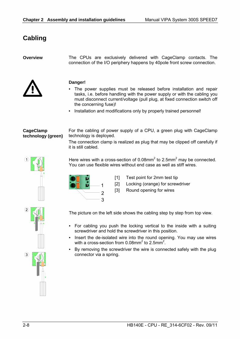
For the cabling of power supply of a CPU, a green plug with CageClamp technology is deployed. The connection clamp is realized as plug that may be clipped off carefully if it is still cabled. Here wires with a cross-section of 0.08mm2 to 2.5mm2 may be connected. You can use flexible wires without end case as well as stiff wires.
123
[1] Test point for 2mm test tip [2] Locking (orange) for screwdriver [3] Round opening for wires
1
2
3
The picture on the left side shows the cabling step by step from top view. • For cabling you push the locking vertical to the inside with a suiting
screwdriver and hold the screwdriver in this position. • Insert the de-isolated wire into the round opening. You may use wires
with a cross-section from 0.08mm2 to 2.5mm2. • By removing the screwdriver the wire is connected safely with the plug
connector via a spring.
Overview
CageClamp technology (green)

Manual VIPA System 300S SPEED7 Chapter 2 Assembly and installation guidelines
HB140E - CPU - RE_314-6CF02 - Rev. 09/11 2-9
In the following the cabling of the two variants are shown:
20pole screw connection VIPA 392-1AJ00
40pole screw connection VIPA 392-1AM00
Open the front flap of your I/O module.
Bring the front connector in cabling position. For this you plug the front connector on the module until it locks. In this position the front connector juts out of the module and has no contact yet.
De-isolate your wires. If needed, use core end cases.
Thread the included cable binder into the front connector.
If you want to lead out your cables from the bottom of the module, start with the cabling from bottom to top, res. from top to bottom, if the cables should be led out at the top.
Bolt also the connection screws of not cabled screw clamps.
Put the included cable binder around the cable bundle and the front connector.
Fix the cable binder for the cable bundle.
continued ...
Front connectors of the in-/output modules

Chapter 2 Assembly and installation guidelines Manual VIPA System 300S SPEED7
2-10 HB140E - CPU - RE_314-6CF02 - Rev. 09/11
... continue 20pole screw connection
VIPA 392-1AJ00 40pole screw connection
VIPA 392-1AM00
Push the release key at the front connector on the upper side of the module and at the same time push the front connector into the module until it locks.
Bolt the fixing screw of the front connector.
Now the front connector is electrically connected with your module.
Close the front flap.
Fill out the labeling strip to mark the single channels and push the strip into the front flap.

Manual VIPA System 300S SPEED7 Chapter 2 Assembly and installation guidelines
HB140E - CPU - RE_314-6CF02 - Rev. 09/11 2-11
Installation guidelines
The installation guidelines contain information about the interference free deployment of System 300 systems. There is the description of the ways, interference may occur in your control, how you can make sure the electromagnetic digestibility (EMC), and how you manage the isolation.
Electromagnetic digestibility (EMC) means the ability of an electrical device, to function error free in an electromagnetic environment without being interferenced res. without interferencing the environment. All System 300 components are developed for the deployment in hard industrial environments and fulfill high demands on the EMC. Nevertheless you should project an EMC planning before installing the components and take conceivable interference causes into account.
Electromagnetic interferences may interfere your control via different ways: • Fields • I/O signal conductors • Bus system • Current supply • Protected earth conductor Depending on the spreading medium (lead bound or lead free) and the distance to the interference cause, interferences to your control occur by means of different coupling mechanisms. One differs: • galvanic coupling • capacitive coupling • inductive coupling • radiant coupling
General
What means EMC?
Possible interference causes

Chapter 2 Assembly and installation guidelines Manual VIPA System 300S SPEED7
2-12 HB140E - CPU - RE_314-6CF02 - Rev. 09/11
In the most times it is enough to take care of some elementary rules to guarantee the EMC. Please regard the following basic rules when installing your PLC. • Take care of a correct area-wide grounding of the inactive metal parts
when installing your components. - Install a central connection between the ground and the protected
earth conductor system. - Connect all inactive metal extensive and impedance-low. - Please try not to use aluminum parts. Aluminum is easily oxidizing
and is therefore less suitable for grounding. • When cabling, take care of the correct line routing.
- Organize your cabling in line groups (high voltage, current supply, signal and data lines).
- Always lay your high voltage lines and signal res. data lines in separate channels or bundles.
- Route the signal and data lines as near as possible beside ground areas (e.g. suspension bars, metal rails, tin cabinet).
• Proof the correct fixing of the lead isolation. - Data lines must be laid isolated. - Analog lines must be laid isolated. When transmitting signals with
small amplitudes the one sided laying of the isolation may be favorable.
- Lay the line isolation extensively on an isolation/protected earth con-ductor rail directly after the cabinet entry and fix the isolation with cable clamps.
- Make sure that the isolation/protected earth conductor rail is connected impedance-low with the cabinet.
- Use metallic or metalized plug cases for isolated data lines. • In special use cases you should appoint special EMC actions.
- Wire all inductivities with erase links, which are not addressed by the System 300V modules.
- For lightening cabinets you should prefer incandescent lamps and avoid luminescent lamps.
• Create a homogeneous reference potential and ground all electrical operating supplies when possible. - Please take care for the targeted employment of the grounding
actions. The grounding of the PLC is a protection and functionality activity.
- Connect installation parts and cabinets with the System 300V in star topology with the isolation/protected earth conductor system. So you avoid ground loops.
- If potential differences between installation parts and cabinets occur, lay sufficiently dimensioned potential compensation lines.
Basic rules for EMC

Manual VIPA System 300S SPEED7 Chapter 2 Assembly and installation guidelines
HB140E - CPU - RE_314-6CF02 - Rev. 09/11 2-13
Electrical, magnetically and electromagnetic interference fields are weakened by means of an isolation, one talks of absorption. Via the isolation rail, that is connected conductive with the rack, interference currents are shunt via cable isolation to the ground. Hereby you have to make sure, that the connection to the protected earth conduc-tor is impedance-low, because otherwise the interference currents may appear as interference cause. When isolating cables you have to regard the following: • If possible, use only cables with isolation tangle. • The hiding power of the isolation should be higher than 80%. • Normally you should always lay the isolation of cables on both sides.
Only by means of the both-sided connection of the isolation you achieve high quality interference suppression in the higher frequency area. Only as exception you may also lay the isolation one-sided. Then you only achieve the absorption of the lower frequencies. A one-sided isolation connection may be convenient, if: - the conduction of a potential compensating line is not possible - analog signals (some mV res. µA) are transferred - foil isolations (static isolations) are used.
• With data lines always use metallic or metalized plugs for serial couplings. Fix the isolation of the data line at the plug rack. Do not lay the isolation on the PIN 1 of the plug bar!
• At stationary operation it is convenient to strip the insulated cable interruption free and lay it on the isolation/protected earth conductor line.
• To fix the isolation tangles use cable clamps out of metal. The clamps must clasp the isolation extensively and have well contact.
• Lay the isolation on an isolation rail directly after the entry of the cable in the cabinet. Lead the isolation further on to the System 300V module and don't lay it on there again!
Please regard at installation! At potential differences between the grounding points, there may be a compensation current via the isolation connected at both sides. Remedy: Potential compensation line
Isolation of conductors

Chapter 2 Assembly and installation guidelines Manual VIPA System 300S SPEED7
2-14 HB140E - CPU - RE_314-6CF02 - Rev. 09/11

Manual VIPA System 300S SPEED7 Chapter 3 Hardware description
HB140E - CPU - RE_314-6CF02 - Rev. 09/11 3-1
Chapter 3 Hardware description
Here the hardware components of the CPU 314ST/DPM are described. The technical data are at the end of the chapter.
Topic Page Chapter 3 Hardware description ..................................................... 3-1
Properties............................................................................................. 3-2 Structure .............................................................................................. 3-3 Components......................................................................................... 3-4 In-/Output range................................................................................... 3-8 Technical Data ................................................................................... 3-11
Overview
Content
Chapter 3 Hardware description Manual VIPA System 300S SPEED7
3-2 HB140E - CPU - RE_314-6CF02 - Rev. 09/11
Properties
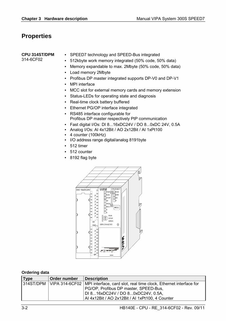
• SPEED7 technology and SPEED-Bus integrated • 512kbyte work memory integrated (50% code, 50% data) • Memory expandable to max. 2Mbyte (50% code, 50% data) • Load memory 2Mbyte • Profibus DP master integrated supports DP-V0 and DP-V1 • MPI interface • MCC slot for external memory cards and memory extension • Status-LEDs for operating state and diagnosis • Real-time clock battery buffered • Ethernet PG/OP interface integrated • RS485 interface configurable for
Profibus DP master respectively PtP communication • Fast digital I/Os: DI 8...16xDC24V / DO 8...0xDC 24V, 0.5A • Analog I/Os: AI 4x12Bit / AO 2x12Bit / AI 1xPt100 • 4 counter (100kHz) • I/O address range digital/analog 8191byte • 512 timer • 512 counter • 8192 flag byte
PWR
RUN
STOP
SF
FRCE
MCC
A
S
RUN
ERR
DE
IF
MCC
RUN
STOP
MRES
X1
X2 X3
X 2
3 4
CPU314STDIO 16xDC24V
.0
.1
.2
.3
.4
.5
.6
.7
.0
.1
.2
.3
.4
.5
.6
.7SF
+0
+1VIPA 314-6CF01
DI
DIO
Type Order number Description 314ST/DPM VIPA 314-6CF02 MPI interface, card slot, real time clock, Ethernet interface for
PG/OP, Profibus DP master, SPEED-Bus, DI 8...16xDC24V / DO 8...0xDC24V, 0.5A, AI 4x12Bit / AO 2x12Bit / AI 1xPt100, 4 Counter
CPU 314ST/DPM 314-6CF02
Ordering data

Manual VIPA System 300S SPEED7 Chapter 3 Hardware description
HB140E - CPU - RE_314-6CF02 - Rev. 09/11 3-3
Structure
[1] LEDs of the integrated Profibus DP master
[2] Storage media slot [3] LEDs of the CPU part [4] LEDs of the I/O part [5] Operating mode switch CPU The following components are under the front flap [6] Slot for DC 24V power supply [7] Twisted pair interface
for Ethernet PG/OP channel [8] MPI interface
PWR
RUN
STOP
SF
FRCE
MCC
A
S
RUN
ERR
DE
IF
MCC
RUNSTOPMRES
X1
X 2
3 4
CPU 314ST
VIPA 314-6CF02
1
2
3
5
X2 X3MPI PB-DP
+-
9
8
7
6
4
.0
.1
.2
.3
.4
.5
.6
.7
.0
.1
.2
.3
.4
.5
.6
.7F
+0
+1DI
DIO
L+
F
X5
L+
[9] Profibus DP/PtP interface
CPU 314ST/DPM 314-6CF02

Chapter 3 Hardware description Manual VIPA System 300S SPEED7
3-4 HB140E - CPU - RE_314-6CF02 - Rev. 09/11
Components
Operating mode switch
RUN
STOP
MRES
With the operating mode switch you may switch the CPU between STOP and RUN. The operating mode START-UP is driven automatically from the CPU between STOP and RUN. Placing the switch to Memory Reset (MRES), you request an overall reset with following load from MMC (project or firmware).
The RJ45 jack serves the interface to the Ethernet PG/OP channel. This interface allows you to program res. remote control your CPU, to access the internal website or to connect a visualization via up to 4 PG/OP connections. Here a transfer rate of 10Mbit at half duplex is supported. For online access to the CPU via Ethernet PG/OP channel valid IP address parameters have to be assigned to this. More may be found at chapter "Deployment CPU ..." at "Initialization Ethernet PG/OP channel". The jack has the following assignment: 8pin RJ45 jack:
Pin Assignment Pin Assignment 1 Transmit + 5 - 2 Transmit - 6 Receive - 3 Receive + 7 -
1 2 3 4 5 6 7 8
4 - 8 -
The MPI interface handles the data exchange between CPU and PC. Via a bus communication you may transfer applications and data between the CPUs that are connected via MPI. For a serial transfer from your PC you normally need a MPI transducer. The MPI-slot has the following pin assignment:
9pin D-type jack: Pin Assignment 1 reserved (must not be connected) 2 M24V 3 RxD/TxD-P (Line B) 4 RTS 5 M5V 6 P5V 7 P24V 8 RxD/TxD-N (Line A)
5
4
3
2
1
9
8
7
6
9 n.c.
Ethernet PG/OP channel
MPI interface

Manual VIPA System 300S SPEED7 Chapter 3 Hardware description
HB140E - CPU - RE_314-6CF02 - Rev. 09/11 3-5
The CPU has got one row of LEDs on the front side. The following table shows you the usage of the LEDs and the according colors:
Label Color Meaning PWR green CPU part is provided with internal 5V RUN green CPU is in the operating mode RUN
STOP yellow CPU is in the operating mode STOP SF red On at system errors (hardware defect)
FRCE yellow On as soon as variables are forced (fixed) MCC yellow Blinks at storage media access
A green Activity: on: physically connected off: no physical connection blinks: shows Ethernet activity
S green Speed: on: 100MBit off: 10MBit
Note! All LEDs of the CPU are blinking three times, when accessing an invalid storage media or when it is pulled out during the reading process.
Power supply
X1
+-
DC 24V
The CPU has an integrated power supply. The power supply has to be provided with DC 24V. For this serves the double DC 24V slot, that is underneath the flap. Via the power supply not only the internal electronic is provided with voltage, but by means of the backplane bus also the connected modules. The power supply is protected against polarity inversion and overcurrent. The internal electronic is galvanically connected with the supply voltage. Please regard that the integrated power supply may supply the backplane bus (SPEED-Bus and Standard bus) with a sum of 5A. Each SPEED-Bus rail has a slot for an external power supply. This allows you to raise the maximum current at the back plane bus for 6A.
The CPU has a load memory and a work memory. These are battery buffered. After project transfer the load memory contains the user program together with its system data. During operation the operation-relevant program code and the user data are copied to the work memory by the operating system of the CPU. The CPU 314-6CF02 has a work memory of about 512kbyte. During program run the work memory is divided into 50% for program and 50% for data. There is the possibility to expand the work memory to max 2Mbyte by means of a MCC memory extension card. The size of the load memory is fixed at 2Mbyte.
LEDs
Memory management

Chapter 3 Hardware description Manual VIPA System 300S SPEED7
3-6 HB140E - CPU - RE_314-6CF02 - Rev. 09/11
As external storage medium for applications and firmware you may use a MMC storage module (Multimedia card) or a MCC memory extension card. The MCC can additionally be used as an external storage medium. Both VIPA storage media are pre-formatted with the PC format FAT16 and can be accessed via a card reader. An access to the storage media always happens after an overall reset and PowerON.
The CPU has an integrated RS485 interface. The functionality of this interface can be configured by the mean of the parameter "Function RS485" in the hardware configuration of the virtual SPEED-Bus. Using the Profibus functionality the integrated Profibus DP master is connected to Profibus via RS485 interface. At master operation there is access to up to 125 DP slaves. For this the project engineering happens in the hardware configurator from Siemens. For state display the CPU has a row of LEDs at its front side. Dependent on the mode of operation these give information according to the following pattern over the operating condition of the Profibus part: RUN green
ERR red
DE green
IF red
Meaning
Master has no project, this means the interface is deactivated respectively PtP is active.
Master has bus parameters and is in RUN without slaves.
Master is in "clear" state (safety state). The inputs of the slaves may be read. The outputs are disabled.
Master is in "operate" state, this means data exchange between master and slaves. The outputs may be accessed.
At least 1 slave is missing.
Initialization error at faulty parameterization.
Waiting state for start command from CPU. RUN green
ERR red
DE green
IF red
Meaning
Slave has no project respectively PtP is active.
Slave is without master.
Alternate flashing at configuration faults.
Slave exchanges data between master.
on: off: flashing:
Storage media slot
RS485 interface with configurable functionality
Profibus functionality
Master operation
Slave operation

Manual VIPA System 300S SPEED7 Chapter 3 Hardware description
HB140E - CPU - RE_314-6CF02 - Rev. 09/11 3-7
Using the PtP functionality the RS485 interface is allowed to connect via serial point-to-point connection to different source res. target systems. Here the following protocols are supported: ASCII, STX/ETX, 3964R, USS and Modbus-Master (ASCII, RTU) RS485 interface of both functionalities have the same pin assignment: 9-pin Profibus SubD jack:
Pin Assignment 1 shield 2 M24V 3 RxD/TxD-P (Line B) 4 RTS 5 M5V 6 P5V 7 P24V 8 RxD/TxD-N (Line A)
5
4
3
2
1
9
8
7
6
9 n.c.
PtP functionality
RS485 interface

Chapter 3 Hardware description Manual VIPA System 300S SPEED7
3-8 HB140E - CPU - RE_314-6CF02 - Rev. 09/11
In-/Output range
The CPU has the following integrated analog and digital in- and output ranges:
PWR
RUN
STOP
SF
FRCE
MCC
RUN
ERR
DE
IF
MCC
RUN
STOP
MRES
X1
X 2
3 4
CPU314ST
VIPA 314-6CF02
X2 X3MP²I PB-DP
+-
.0
.1
.2
.3
.4
.5
.6
.7
.0
.1
.2
.3
.4
.5
.6
.7 F
+0
+1
DIDIO
2L+
1L+
F
• AI 4x12Bit, 1xPt100 • AO 2x12Bit • DI 8xDC24V alarm capable,
the first 8 inputs parameterizable as 4 counters (100kHz)
• DIO 8xDC24V, 0.5A
Analog part Digital part L+
CH1
1
2
3
4
5
14
15
16
17
18
19
20
6
7
8
9
10
11
12
13CH3
CH4
CH5
Pt100
M
A
VCH0
A
V
CH2A
V
A
V
CH6
24V DC
AI
AO
ANA
DC 24V
21
22
23
24
25
26
27
28
29
30 M
DI
DC 24V
31
32
33
34
35
36
37
38
39
40 M
L+
DIO
L+
Overview
Pin assignment

Manual VIPA System 300S SPEED7 Chapter 3 Hardware description
HB140E - CPU - RE_314-6CF02 - Rev. 09/11 3-9
The analog part consists of 4 input, 1 Pt100 and 2 output channels. 10byte for input and 4byte for output are used for the process image. The channels of the module are galvanically separated from the SPEED-Bus via DC/DC transducer and optocouplers.
Attention! Temporarily not used analog inputs with activated channel must be connected to the concerning ground.
Pin 1 2 3 4 5 6 7 8 9
10 11 12 13 14 15 16 17 18 19 20
Assignment Power supply DC 24V for analog range Voltage meas. channel 0 Current meas. channel 0 Ground channel 0 Voltage meas. channel 1 Current meas. channel 1 Ground channel 1 Voltage meas. channel 2 Current meas. channel 2 Ground channel 2 Voltage meas. channel 3 Current meas. channel 3 Ground channel 3 Pt 100 channel 4 Pt 100 channel 4 Output + channel 5 Ground output channel 5 Output + channel 6 Ground output channel 6 Ground power supply for analog range
Connection
L+ DC 24V
CH1
1
2
3
4
5
14
15
16
17
18
19
20
6
7
8
9
10
11
12
13CH3
CH4
CH5
Pt100
M
A
VCH0
A
V
CH2A
V
A
V
CH6
AI
AO
ANA
LEDs
VIPA 314-6CF01
.0
.1
.2
.3
.4
.5
.6
.7
2L+.0.1.2.3.4.5.6.7 F
+0
+1
DIDIO
L+
FF
1L+
1L+
F
LED (green) Supply voltage available LED (red) Sum error
Note! To avoid measuring errors, you should connect only one measuring type per channel.
Analog part
Status indicator Pin assignment

Chapter 3 Hardware description Manual VIPA System 300S SPEED7
3-10 HB140E - CPU - RE_314-6CF02 - Rev. 09/11
The digital part consists of 8 inputs and 8 in-/outputs. Each of this in-/ outputs monitors its state via a LED. Via the parameterization you may assign alarm properties to every digital input. Additionally the digital inputs are parameterizable as counter. The output channels provide a diagnostic function, i.e. as soon as an output is active, the according input is set to "1". At a short circuit at the load, the input is pulled to "0" and by evaluating the input, the error may be recognized. The DIO part has to be provided with external DC 24V.
Pin
21 22 23 24 25 26 27 28 29 30 31 32 33 34 35 36 37 38 39 40
Assignment Power supply +DC 24V I+0.0 / Counter 0(A) I+0.1 / Counter 0(B) I+0.2 / Gate0/Latch0/Reset0 I+0.3 / Counter 1(A) I+0.4 / Counter 1(B) I+0.5 / Gate1/Latch1/Reset1 I+0.6 / Counter 2(A) I+0.7 / Counter 2(B) Ground DI Power supply +DC 24V I/Q+1.0 / Gate2/Latch2/Reset2 I/Q+1.1 / Counter 3(A) I/Q+1.2 / Counter 3(B) I/Q+1.3 / Gate3/Latch3/Reset3 I/Q+1.4 / OUT0/Latch0/Reset0 I/Q+1.5 / OUT1/Latch1/Reset1 I/Q+1.6 / OUT2/Latch2/Reset2 I/Q+1.7 / OUT3/Latch3/Reset3 Ground DIO
Connection
DC 24V
21
22
23
24
25
26
27
28
29
30 M
DI
DC24V
31
32
33
34
35
36
37
38
39
40 M
L+
DIO
L+
LEDs
VIPA 314-6CF01
.0
.1
.2
.3
.4
.5
.6
.7
2L+.0.1.2.3.4.5.6.7 F
+0
+1
DIDIO
.0 ... .7
FF
1L+
.0 ... .7
L+
DI: .0 ... .7 DIO: 2L+ .0 ... .7 F
LEDs (green) I+0.0 to I+0.7 (each Byte) Starting with app. 15V the signal "1" at the input is recognized and the according LED LED (green) Supply voltage available for DIO LEDs (green) I/Q+1.0 to I/Q+1.7 on at active output/input LED (red) Overload or short circuit error
Attention! Please take care that the voltage at an output channel always is ≤ the supply voltage via L+. Further you have to regard that due to the parallel connection of in- and output channel per group a set output can be provided via a connected input signal. A thus set output remains active at connected input signal also the power supply is turned off. Nonobservance may destroy the module.
Digital part
Status indicator Pin assignment

Manual VIPA System 300S SPEED7 Chapter 3 Hardware description
HB140E - CPU - RE_314-6CF02 - Rev. 09/11 3-11
Technical Data
Electrical Data VIPA 314-6CF02 Power supply DC 24V Current consumption max. 1.5A Output current to backplane bus max. 5A (Standard bus and SPEED-Bus) Status display (LEDs) via LEDs at the front Work memory - integrated Code Data
256kbyte 256kbyte
- expandable Code Data
1Mbyte 1Mbyte
Load memory 2Mbyte External storage media MMC (Memory Card), MCC memory extension card Slots / Interfaces MPI
MPI interface - Transfer rate: max. 187.5kbaud - max. 32 connections
RJ45 PG/OP channel PG/OP channel via Ethernet with max. 4 connections RS485 Configurable functionality via project engineering: deactivated
Profibus DP Communication - Transfer rate: 9.6kbaud to 12Mbaud - Max. number of partners: 32 stations in every segment without repeater, wit100 h Repeater expandable to 126. - Protocol: DP-V0, DP-V1, PG/OP communication
PtP Communication - Transfer rate: 0.15kbaud to 115.2kbaud - Max. number of partners: ASCII, RTX/ETX, 3964R: 1 Modbus: 256 Stations, USS: 64 Stations - Protocol: ASCII, STX/ETX, 3964R, USSMaster, Modbus ASCIIMaster/RTUMaster
SPEED-Bus - Data rate 64Mbaud - Current consumption 400mA Battery buffer / clock Lithium battery, 30 days buffer / yes Execution time CPU for bit operation, min. for word operation, min. for fixed-point calculation, min. for floating-point calculation, min.
0.010µs 0.010µs 0.010µs 0.058µs
Flag byte / Timer / Counter 8192 / 512 / 512 Number of blocks FBs 2048, FCs 2048, DBs 4095
continued ...

Chapter 3 Hardware description Manual VIPA System 300S SPEED7
3-12 HB140E - CPU - RE_314-6CF02 - Rev. 09/11
... continue Technical Data Digital Output DO 8...0xDC 24V, 0.5A Nominal load voltage DC 24V from ext. power supply No-load current consumption at L+ 30mA (all A.x=off) Output current per channel 0.5A short-circuit proof Isolation in groups per 8, 500Veff (field voltage - backplane bus)Analog In-/Output AI 4x12Bit / AO 2x12Bit / AI 1xPt100 Number of Current-/Voltage input 4 Number of resistance input 1 Number of outputs 2 Length of cable: shielded 200m Voltages, Currents, Potentials Supply voltage L+ DC 24V - reverse polarity protection yes Constant current for resistance sensor 1.25mA Isolation - channel / backplane (SPEED-Bus) - channel / power supply electronic - between the channels
yes yes no
Permitted potential difference - between the inputs (UCM) - between the inputs and MINTERNAL (UISO)
DC 11V DC 75V / AC 60V
Isolation tested with DC 500V Current consumption - from the back plane bus - - from the power supply L+ 85mA (without load) Power dissipation of the module 2W Analog value calculation input Conversion time/Resolution (per channel) Measuring principle Sigma-delta Parameterizable yes Conversion rate (Hz) 200 170 120 60 30 15 7.5 3.7 Integration time (ms) 5 6 8 17 33 67 133 270 Basic conversion time (ms) 6 7 9 18 34 68 134 268 Resolution (Bit) incl. overrange 10 12 14 15 16 16 16 16
Noise suppression for frequency f1 (Hz) no 50 and 60Hz Basic execution time of the module, in ms (all channels enabled) 30 35 45 90 170 340 670 1340
Smoothing of the measured values none Analog value calculation output channels
Resolution (incl. overrange) ±10V, ±20mA 11bit + sign 0 ... 10V, 0 ... 20mA 11bit 4 … 20mA 10bit Conversion time (per channel) 1.0ms Settling time - impedance load 0.2ms - capacitive load 0.5ms - inductive load 0.2ms
continued ...

Manual VIPA System 300S SPEED7 Chapter 3 Hardware description
HB140E - CPU - RE_314-6CF02 - Rev. 09/11 3-13
... continue Technical data Suppression of interference, limits of error input channels Noise suppression for f=n x (f1 ±1%) (f1=interference frequency, n=1,2,...) Common-mode interference (UCM < 11V) > 80dB Series-mode noise (peak value of noise < nominal value of input range)
> 80dB
Crosstalk between the inputs > 50dB Operational limit (only valid to 120W/s) (in the entire temperature range, referring to input range) Measuring range Tolerance voltage input 0 ... 10V ±0.4% ±10V ±0.3% current input ±20mA ±0.3% 0 ... 20mA ±0.6% 4 ... 20mA ±0.8% Resistor 0 ... 600Ω ±0.4% Resistance thermometer Pt100, Pt1000 ±0.6% Ni100, Ni1000 ±1.0% Basic error limit (only valid to 120W/s) (during temperature is 25°C, referring to input range) Voltage input 0 ... 10V ±0.3% ±10V ±0.2% Current input ±20mA ±0.2% 0 ... 20mA ±0.4% 4 ... 20mA ±0.5% Resistors 0 ... 600Ω ±0.2% Resistance thermometer Pt100, Pt1000 ±0.5K Ni100, Ni1000 ±0.5K Temperature error (with reference to the input range)
±0.005%/K Linearity error (with reference to the input range) ±0.02%
Repeatability (in steady state at 25°C referred to the input range) ±0.05%
Suppression of interference, limits of error output channels Crosstalk between the outputs > 40dB Operational limit (in the entire temperature range, referring to output range) Measuring range Tolerance Voltage output 0 ... 10V ±0.8% ±10V ±0.4% Current output ±20mA ±0.4%1) 0 ... 20mA ±0.6%1) 4 ... 20mA ±0.8%1)
continued...

Chapter 3 Hardware description Manual VIPA System 300S SPEED7
3-14 HB140E - CPU - RE_314-6CF02 - Rev. 09/11
... continue Technical data Basic error limit (during temperature is 25°C, referring to output range) Measuring range Tolerance Voltage output 0 ... 10V ±0.6% ±10V ±0.3% Current output ±20mA ±0.3%1) 0 ... 20mA ±0.4%1) 4 ... 20mA ±0.5%1) Temperature error (with reference to the output range)
±0.01%/K
Linearity error (with reference to the output range)
±0.05%
Repeatability (in steady state at 25°C referred to the output range)
±0.05%
Output ripple; range 0 to 50kHz (referred to output range)
±0.05%
States, Alarms, Diagnostic Diagnostic alarm parameterizable Diagnostic functions - Sum error monitor red LED (F) - Diagnostic information readable possible Substitute value can be applied yes Data for choosing an encoder Voltage input ±10V, 0 ... 10V 120kΩ Current input ±20mA, 0 ... 20mA, 4 ... 20mA 33Ω Resistors 0...600Ω 10MΩ Resistance thermometer Pt100, Pt1000, Ni100, Ni1000 10MΩ Maximum input voltage for voltage input (destruction limit)
25V
Maximum input current for current input (destruction limit)
30mA
Connection of the sensor - For measuring voltage yes - For measuring current as 2wire transmitter possible with external power supply as 4wire transmitter yes - For measuring resistance with 2conductor connection yes Characteristic linearization for Resistance thermometer Pt100, Pt1000, Ni100, Ni1000
continued ...

Manual VIPA System 300S SPEED7 Chapter 3 Hardware description
HB140E - CPU - RE_314-6CF02 - Rev. 09/11 3-15
... continue Technical data Data for choosing an actuator Output ranges (rated values) - Voltage 0 ... 10V, ±10V - Current 4 ... 20mA, 0 ... 20mA, ±20mA Load resistance (in nominal range of the output)
- At voltage outputs min. 1kΩ capacitive load max. 1µF - At current output max. 500Ω Inductive load max. 10mH Voltage outputs - Short-circuit protection yes - Short-circuit current max. 31mA Current outputs - No-load voltage max. 13V Destruction limit against voltages/currents applied from outside
- Voltage at outputs to MANA max. 15V - Current max. 30mA Connection of actuators - for voltage output 2conductor connection - for current output 2conductor connection Dimensions and weight Dimensions (WxHxD) in mm 80x125x120 Weight 480g
1) The error limits are measured with a load of R=10Ω.

Chapter 3 Hardware description Manual VIPA System 300S SPEED7
3-16 HB140E - CPU - RE_314-6CF02 - Rev. 09/11

Manual VIPA System 300S SPEED7 Chapter 4 Deployment CPU 314ST/DPM
HB140E - CPU - RE_314-6CF02 - Rev. 09/11 4-1
Chapter 4 Deployment CPU 314ST/DPM
This chapter describes the employment of a CPU 314ST/DPM with SPEED7 technology in the System 300. The description refers directly to the CPU and to the employment in connection with peripheral modules that are mounted on a profile rail together with the CPU at the standard bus or the SPEED-Bus.
Topic Page Chapter 4 Deployment CPU 314ST/DPM......................................... 4-1
Assembly Standard-Bus....................................................................... 4-2 Assembly SPEED-Bus ......................................................................... 4-3 Start-up behavior.................................................................................. 4-6 Addressing ........................................................................................... 4-7 Initialization Ethernet PG/OP channel ................................................ 4-11 Access to the internal Web page........................................................ 4-14 Project engineering ............................................................................ 4-16 Setting standard CPU parameters...................................................... 4-22 Setting VIPA specific CPU parameters............................................... 4-29 Parameterization of modules.............................................................. 4-33 Project transfer................................................................................... 4-34 Operating modes................................................................................ 4-38 Overall reset....................................................................................... 4-41 Firmware update ................................................................................ 4-43 Factory reset ...................................................................................... 4-46 Memory extension with MCC.............................................................. 4-47 Extended know-how protection........................................................... 4-48 MMC-Cmd - Auto commands ............................................................. 4-50 VIPA specific diagnostic entries ......................................................... 4-52 Using test functions for control and monitoring of variables................ 4-56
Overview
Content

Chapter 4 Deployment CPU 314ST/DPM Manual VIPA System 300S SPEED7
4-2 HB140E - CPU - RE_314-6CF02 - Rev. 09/11
Assembly Standard-Bus
SLOT1DCDC
SLOT2
horizontal assembly
lying assembly
verticalassembly
Assembly possibilities Please regard the allowed environment temperatures:
• horizontal assembly: from 0 to 60°C • vertical assembly: from 0 to 40°C • lying assembly: from 0 to 40°C
If you do not deploy SPEED-Bus modules, the assembly happens with the following approach: • Bolt the profile rail with the background (screw size: M6),
so that you still have minimum 65mm space above and 40mm below the profile rail.
• If the background is a grounded metal or device plate, please look for a low-impedance connection between profile rail and background.
• Connect the profile rail with the protected earth conductor. For this purpose there is a bolt with M6-thread.
• The minimum cross-section of the cable to the protected earth conductor has to be 10mm2.
• Stick the power supply to the profile rail and pull it to the left side to the grounding bolt of the profile rail.
• Fix the power supply by screwing. • Take a backplane bus connector and click it at the CPU
from the backside like shown in the picture. • Stick the CPU to the profile rail right from the power supply
and pull it to the power supply.
• Click the CPU downwards and bolt it like shown. • Repeat this procedure with the peripheral modules, by
clicking a backplane bus connector, stick the module right from the modules you've already fixed, click it downwards and connect it with the backplane bus connector of the last module and bolt it.
Danger! • The power supplies must be released before installation and repair
tasks, i.e. before handling with the power supply or with the cabling you must disconnect current/voltage (pull plug, at fixed connection switch off the concerning fuse)!
• Installation and modifications only by properly trained personnel!
Manual VIPA System 300S SPEED7 Chapter 4 Deployment CPU 314ST/DPM
HB140E - CPU - RE_314-6CF02 - Rev. 09/11 4-3
Assembly SPEED-Bus
For the deployment of SPEED-Bus modules, a pre-manufactured SPEED-Bus rail is required. This is available mounted on a profile rail with 2, 6 or 10 extension plug-in locations.
SLOT1DCDC
CPUSLOT2SLOT3SLOT4SLOT5SLOT6
SLOT1DCDC
CPUSLOT2
65mm
40mm
SLOT1DCDC
CPUSLOT2
• Bolt the profile rail with the background (screw size: M6), so that you still have minimum 65mm space above and 40mm below the profile rail.
• Please look for a low-impedance connection between profile rail and background
• Connect the profile rail with the protected earth
conductor. The minimum cross-section of the cable to the
protected earth conductor has to be 10mm2.
Profile rail
G
122
Order number SPEED-
Bus slotA B C
VIPA 390-1AB60 - 160mm 140mm 10mmVIPA 390-1AE80 - 482mm 466mm 8.3mmVIPA 390-1AF30 - 530mm 500mm 15mmVIPA 390-1AJ30 - 830mm 800mm 15mm
VIPA 390-9BC00* - 2000mm - 15mmVIPA 391-1AF10 2 530mm 500mm 15mmVIPA 391-1AF30 6 530mm 500mm 15mmVIPA 391-1AF50 10 530mm 500mm 15mm
* Unit pack 10 pieces
Pre-manufactured SPEED-Bus profile rail
Installation of the profile rail

Chapter 4 Deployment CPU 314ST/DPM Manual VIPA System 300S SPEED7
4-4 HB140E - CPU - RE_314-6CF02 - Rev. 09/11
1 2 3
• Dismantle the according protection flaps of the SPEED-Bus plug-in locations with a screw driver (open and pull down). For the SPEED-Bus is a parallel bus, not all SPEED-Bus plug-in locations must be used in series. Leave the protection flap installed at an unused SPEED-Bus plug-in location.
• At deployment of a DC 24V power supply, install it at the shown position at the profile rail at the left side of the SPEED-Bus and push it to the left to the isolation bolt of the profile rail.
• Fix the power supply by screwing.
SLOT1DCDC
CPUSLOT2
• To connect the SPEED-Bus modules, plug it between the triangular positioning helps to a plug-in location marked with "SLOT ..." and pull it down.
• Only the "SLOT1 DCDC" allows you to plug-in either a SPEED-Bus module or an additional power supply.
• Fix the modules by screwing.
SLOT1DCDC
CPUSLOT2
SLOT2
• To deploy the SPEED7-CPU exclusively at the SPEED-Bus, plug it between the triangular positioning helps to the plug-in location marked with "CPU SPEED7" and pull it down.
• Fix the CPU by screwing.
Installation SPEED-Bus-Module
Installation CPU without Standard-Bus-Modules

Manual VIPA System 300S SPEED7 Chapter 4 Deployment CPU 314ST/DPM
HB140E - CPU - RE_314-6CF02 - Rev. 09/11 4-5
SLOT1DCDC
CPUSLOT2
SLOT2
• If also standard modules shall be plugged, take a bus coupler and click it at the CPU from behind like shown in the picture.
• Plug the CPU between the triangular positioning helps to the plug-in location marked with "CPU SPEED7" and pull it down.
• Fix the CPU by screwing.
SLOT1DCDC
CPUSLOT2
• Repeat this procedure with the peripheral modules, by clicking a backplane bus coupler, stick the module right from the modules you've already fixed, click it downwards and connect it with the backplane bus coupler of the last module and bolt it.
Danger! • Before installing or overhauling the System 300V, the power supplies
must be disconnected from voltage (pull the plug or remove the fuse)! • Installation and modifications only by properly trained personnel!
Installation CPU with Standard-Bus-Modules
Installation Standard-Bus-Modules

Chapter 4 Deployment CPU 314ST/DPM Manual VIPA System 300S SPEED7
4-6 HB140E - CPU - RE_314-6CF02 - Rev. 09/11
Start-up behavior
After the power supply has been switched on, the CPU changes to the operating mode the operating mode lever shows. Now you may transfer your project to the CPU via MPI from your configuration tool res. plug in a MMC with your project and run an overall reset. The following picture shows the approach once more:
PWR
RUN
STOP
SF
FRCE
MCC
PWR
RUN
STOP
SF
FRCE
MCC
PWR
RUN
STOP
SF
FRCE
MCC
PWR
RUN
STOP
SF
FRCE
MCC
1 2 3 4
3 Sec.
3 Sec.
RUN
STOP
MRES
RUN
STOP
MRES
RUN
STOP
MRES
RUN
STOP
MRES
Note! The transfer of the application program from the MMC into the CPU takes always place after an overall reset! When the CPU is delivered it has been reset. After a STOP→RUN transition the CPU switches to RUN without program.
The CPU switches to RUN with the program stored in the battery buffered RAM. The accumulator/battery is automatically loaded via the integrated power supply and guarantees a buffer for max. 30 days. If this time is exceeded, the battery may be totally discharged. This means that the battery buffered RAM is deleted. In this state, the CPU executes an overall reset. If a MMC is plugged, program code and data blocks are transferred from the MMC into the work memory of the CPU. If no MMC is plugged, the CPU transfers permanent stored "protected" blocks into the work memory if available. Information about storing protected blocks in the CPU is to find in this chapter at "Extended Know-how protection". Depending on the position of the RUN/STOP lever, the CPU switches to RUN res. remains in STOP. This event is stored in the diagnostic buffer as: "Start overall reset automatically (unbuffered PowerON)".
Turn on power supply
Overall reset
Default boot procedure, as delivered
Boot procedure with valid data in the CPU
Boot procedure with empty battery

Manual VIPA System 300S SPEED7 Chapter 4 Deployment CPU 314ST/DPM
HB140E - CPU - RE_314-6CF02 - Rev. 09/11 4-7
Addressing
To provide specific addressing of the installed peripheral modules, certain addresses must be allocated in the CPU. At the start-up of the CPU, this assigns automatically peripheral addresses for digital in-/output modules starting with 0 and ascending depending on the slot location. If no hardware project engineering is available, the CPU stores at the addressing analog modules to even addresses starting with 256. Modules at the SPEED-Bus are also taken into account at the automatic address allocation. Here the digital I/Os are stored beginning with address 128 and analog I/Os, FMs and CPs beginning with address 2048.
The SPEED7-CPU provides an I/O area (address 0 ... 8191) and a process image of the in- and outputs (each address 0 ... 255). The process image stores the signal states of the lower address (0 ... 255) additionally in a separate memory area. The process image this divided into two parts: • process image to the inputs (PII) • process image to the outputs (PIQ)
I/O area0....
255....
8191
Process image0...
255
0...
255
InputsPII
OutputsPIQ
The process image is updated automatically when a cycle has been completed.
In the hardware configurator from Siemens you may parameterize maximum up to 8 modules per row. At employment of SPEED7-CPUs you may control up to 32 modules at the standard bus and 10 further modules at the SPEED-Bus. CPs and DP masters that are additionally virtual configured at the standard bus are taken into the count of 32 modules at the standard bus. For the project engineering of more than 8 modules you may use virtual line interface connections. For this you set in the hardware configurator the module IM 360 from the hardware catalog to slot 3 of your 1. profile rail. Now you may extend your system with up to 3 profile rails by starting each with a IM 361 from Siemens at slot 3.
Overview
Addressing Backplane bus I/O devices
Up to 32 modules in one row

Chapter 4 Deployment CPU 314ST/DPM Manual VIPA System 300S SPEED7
4-8 HB140E - CPU - RE_314-6CF02 - Rev. 09/11
You may access the modules with read res. write accesses to the peripheral bytes or the process image. To define addresses a hardware configuration via a virtual Profibus system by including the SPEEDBUS.GSD may be used. For this, click on the properties of the according module and set the wanted address. Attention! Please take care not to configure a double address assignment at connection via external Profibus-DP masters - required for project engineering of a SPEED-Bus system! At external DP master systems, the Siemens hardware configurator does not execute an address check! If you do not like to use a hardware configuration, an automatic addressing comes into force. At the automatic address allocation DIOs occupy depending on the slot location always 4byte and AIOs, FMs, CPs always 16byte at the standard bus and 256byte at the SPEED-Bus. Depending on the slot location the start address from where on the according module is stored in the address range is calculated with the following formulas: DIOs: Start address = 4⋅(slot -1) AIOs, FMs, CPs: Start address = 16⋅(slot -1)+256 DIOs: Start address = 4⋅(slot -101)+128 AIOs, FMs, CPs: Start address = 256⋅(slot -101)+2048 All information to this you may find in the following illustration:
CPU
101102103104 1 2 3 4
... ,102 ,101 1, 2, ...
StartAddress
digital:analog:
1282048
1322304
1362560
1402816
12304
8288
4272
0256
slot number
Define addresses by hardware configuration
Automatic addressing
Standard bus
SPEED-Bus

Manual VIPA System 300S SPEED7 Chapter 4 Deployment CPU 314ST/DPM
HB140E - CPU - RE_314-6CF02 - Rev. 09/11 4-9
The following sample shows the functionality of the automatic address allocation separated for standard bus and SPEED-Bus:
0..8
9....12
13..255
256...320...335......
2048...8191
0
1.......12
13...255
256....272
287....2048...8191
PII
CPU
Input Byte
Address Periphery area
Input Byte
Input Byte
Output Byte
Periphery area Address
anal
ogdi
gita
l
anal
ogdi
gita
l
PIQ
Slot number: 1 2 3 4 5
Input Byte
up to max 255
Output Byte
Output Byte
Output Byte
Output Byte
Output Byte...
Input Byte
Input Byte
Standard busSPEED-Bus
DI 1
6xD
C24
V
AI 8
x12B
it
DO
16x
DC
24V
DIO
16x
DC
24V
AO
4x1
2Bit
up to max 255
PII
Input Byte
Address Periphery area
...
Input Byte
Input Byte
Output Byte
Periphery area Address
anal
ogdi
gita
l
anal
ogdi
gita
l
PIQ
Slot number: 105 104 103 102 101 (Slot 5) (Slot 4) (Slot 3) (Slot 2) (Slot 1)
Input Byte
Input Byte
Input Byte
up to max 255 up to max 255
Output Byte
Output Byte
Output Byte
Output Byte
Output Byte
CPU
Standard busSPEED-Bus
DI 1
6xD
C24
V
AI 8
x12B
it
DO
16x
DC
24V
DIO
16x
DC
24V
AO 4
x12B
it
0........132
133.........144
145......255.........2048......2816
2831...8191
0........132
133........136
137......255.........2048.....2055.........8191
Example for automatic address allocation

Chapter 4 Deployment CPU 314ST/DPM Manual VIPA System 300S SPEED7
4-10 HB140E - CPU - RE_314-6CF02 - Rev. 09/11
By including the SPEEDBUS.GSD in your hardware configurator the module is at your disposal in the hardware catalog. After the installation of the GSD you'll find the CPU 314ST/DPM under Additional field devices \ I/O \ VIPA_SpeedBus. In case there is no hardware configuration available, the in- and output areas starting at address 1024 are shown in the address range of the CPU. For the data input a range of 48byte and for the data output a range of 24byte is available:
Address Access Assignment +0 Byte Digital Input I+0.0 ... I+0.7 +1 Byte Digital Input I+1.0 ... I+1.7 +2 Word reserved +4 Word Analog Input CH0 +6 Word Analog Input CH1 +8 Word Analog Input CH2 +10 Word Analog Input CH3 +12 Word Analog Input CH4 +14 Word reserved +16 Double word Counter 0 / Latch 0 +20 Word reserved +22 Word Status Counter 0 +24 Double word Counter 1 / Latch 1 +28 Word reserved +30 Word Status Counter 1 +32 Double word Counter 2 / Latch 2 +36 Word reserved +38 Word Status Counter 2 +40 Double word Counter 3 / Latch 3 +44 Word reserved +46 Word Status Counter 3
Address Access Assignment +0 Byte reserved +1 Byte Digital Output Q+1.0 ... Q+1.7 +2 Word reserved +4 Word Analog Output CH0 +6 Word Analog Output CH1 +8 Word reserved +10 Word Status Counter 0 +12 Word reserved +14 Word Status Counter 1 +16 Word reserved +18 Word Status Counter 2 +20 Word reserved +22 Word Status Counter 3
Address assignment
Input range
Output range

Manual VIPA System 300S SPEED7 Chapter 4 Deployment CPU 314ST/DPM
HB140E - CPU - RE_314-6CF02 - Rev. 09/11 4-11
Initialization Ethernet PG/OP channel
Every CPU 314ST/DPM has an integrated Ethernet PG/OP channel. This channel allows you to program and remote control your CPU with up to 4 connections. The PG/OP channel also gives you access to the internal web page that contains information about firmware version, connected I/O devices, current cycle times etc. For online access to the CPU via Ethernet PG/OP channel valid IP address parameters have to be assigned to this by means of the Siemens SIMATIC manager. This is called "initialization".
There are the following possibilities for assignment of IP address parameters (initialization): • PLC functions with Assign Ethernet address
(starting with firmware V. 1.6.0) • Hardware project engineering with CP (Minimal project) For the hardware configuration the following software is necessary: • SIMATIC Manager from Siemens V. 5.1 or higher • SIMATIC NET
Please consider that this functionality is supported starting from the firmware version V. 1.6.0. The initialization takes place after the following proceeding: • Determine the current Ethernet (MAC) address of your Ethernet PG/OP
channel. This always may be found as 1st address under the front flap of the CPU on a sticker on the left side.
Ethernet addressEthernet PG/OP
Overview
Possibilities for Initialization
Requirements
Initialization via PLC functions

Chapter 4 Deployment CPU 314ST/DPM Manual VIPA System 300S SPEED7
4-12 HB140E - CPU - RE_314-6CF02 - Rev. 09/11
• Establish a network connection between Ethernet PG/OP channel of the CPU and PC.
• Start the Siemens SIMATIC manager at the PC • Set via Options > Set PG/PC Interface the Access Path to
"TCP/IP -> Network card .... Protocol RFC 1006". • Open with PLC > Assign Ethernet Address the dialog window for
"initialization" of a station.
• Use the [Browse] button to determine the CPU components via MAC
address. As long as the Ethernet PG/OP channel was not initialized yet, this owns the IP address 0.0.0.0 and the station name "Onboard PG/OP".
• Choose the determined module and click to [OK]. • Set the IP configuration by entering IP address, subnet mask and net
transition. In addition an IP address may be received from a DHCP server. For this depending upon the selected option the MAC address, device name or the Client ID, which may be entered here, is to be conveyed to the DHCP server. The Client-ID is a character sequence from maximally 63 characters. Here the following indications may be used: Dash "-", 0-9, A-z, A-Z
• Confirm your settings by button [Assign Address] Direct after the assignment the Ethernet PG/OP channel may be reached by the Siemens SIMATIC manager by means of these IP address parameters and the Access Path "TCP/IP -> Network card .... Protocol RFC 1006".

Manual VIPA System 300S SPEED7 Chapter 4 Deployment CPU 314ST/DPM
HB140E - CPU - RE_314-6CF02 - Rev. 09/11 4-13
• Establish a network connection between Ethernet PG/OP channel of the CPU and PC.
• Start the SIMATIC Manager from Siemens and create a new project. • Add a new System 300 station via Insert > Station > SIMATIC 300-
Station. • Activate the station "SIMATIC 300" and open the hardware configurator
by clicking on "Hardware". • Engineer a rack (SIMATIC 300 \ Rack-300 \ Profile rail) • For the SPEED7-CPUs are configured as CPU 318-2, choose the CPU
318-2 with the order no. 6ES7 318-2AJ00-0AB0 V3.0 from the hardware catalog. You'll find this at SIMATIC 300 \ CPU 300 \ CPU 318-2.
• Include the CP 343-1EX11 at slot 4 (SIMATIC 300 \ CP 300 \ Industrial Ethernet \ CP 343-1).
• Type the wanted IP address and subnet mask into the dialog window of "Properties" of the CP 343-1 and connect the CP with "Ethernet".
• Save and compile your project. • Transfer your project via MPI or MMC into your CPU. More information
about transfer methods may be found in the chapter "Project transfer".
Direct after the assignment the Ethernet PG/OP channel may be reached by the Siemens SIMATIC manager by means of these IP address parameters and the Access Path "TCP/IP -> Network card .... Protocol RFC 1006".
Initialization via minimal project

Chapter 4 Deployment CPU 314ST/DPM Manual VIPA System 300S SPEED7
4-14 HB140E - CPU - RE_314-6CF02 - Rev. 09/11
Access to the internal Web page
The Ethernet PG/OP channel provides a web page that you may access via an Internet browser by its IP address. The web page contains information about firmware versions, current cycle times etc. The current content of the web page is stored on MMC by means of the MMC-Cmd WEBPAGE. More information may be found at "MMC-Cmd - Auto commands". A PG/OP channel connection should be established between PC with Internet browser and CPU 314ST/DPM. This may be tested by Ping to the IP address of the PG/OP channel.
Web page
The access takes place via the IP address of the Ethernet PG/OP channel. The web page only serves for information output. The monitored values are not alterable.
CPU WITH ETHERNET PG/OP Slot 100 VIPA 314-6CF02 V.... Px000077.pkg, SERIALNUMBER 11343
Order no., firmware vers., package, serial no.
SUPPORTDATA : PRODUCT V3420, HARDWARE V0110, 5679G-V10, HX000026.100, Bx000227 V6420, Ax000086 V1200, Ax000056 V0200, fx000007.wld V1120, FlashFileSystem:V102
Information for support
Memorysizes (Bytes): LoadMem : 524288, WorkMemCode : 262144, WorkMemData : 262144
Information about memory configuration, load memory, work memory (code/data)
OnBoardEthernet : MacAddress : 0020D5772C4F, IP-Address : , SubnetMask : , Gateway :
Ethernet PG/OP: Addresses
Cpu state : Stop CPU status FunctionRS485 X2/COM1: MPI FunctionRS485 X3/COM2: DPM-async
Operating mode RS485 (MPI: MPI operation, DPM: DP master)
Cycletime [microseconds] : min=0 cur=0 ave=0 max=0
CPU cycle time: min= minimal cur= current max= maximal
MCC-Trial-Time: 70:23 Remaining time in hh:mm for deacti-vation of the expansion memory if MCC is removed.
ArmLoad [percent] : cur11, max=33 Information for support Additional CPU components:
Slot 201 Slot 201 (DP master): VIPA 342-1DA70 V3.1.9 Px000062.pkg, Name, firmware version, package SUPPORTDATA : PRODUCT V3190, BB000218 V5190, AB000068 V4160, ModuleType CB2C0010, Cycletime [microseconds] : min=65535000 cur=0 ave=0 max=0 cnt=0
Information for support
continued ...
Access to the web page
Requirements

Manual VIPA System 300S SPEED7 Chapter 4 Deployment CPU 314ST/DPM
HB140E - CPU - RE_314-6CF02 - Rev. 09/11 4-15
... continue
Slot 206 Slot 206 (I/Os): HS_DI8_DIO8_AI5_AO2, V2.0.6 Px000025.pkg, Name, firmware version, package SUPPORTDATA :
BB000156 V2060, AB000073 V2020, AB000074 V2000 PRODUCT V2060, Hx000012 V1000 ModuleType 8400000 Address Input 1024...1071 Address Output 1024...1071
Information for support
SPEED-BUS Modules at the speed bus Slot 101 VIPA 321-1BH70 V1.0.1 Px000029.pkg Name, firmware version, package SUPPORTDATA : BB000189 V1010, AB000076 V1010, PRODUCT V1010, Hx000013 V1000, ModuleType 1FC20001 Address Input 128...131
Information for support
Slot 102 VIPA 322-1BH70 V1.0.1 Px000030.pkg Name, firmware version, package SUPPORTDATA : BB000190 V1010, AB000077 V1000, PRODUCT V1010, Hx000014 V1000, ModuleType AFD00001
Address Input 132...135
Information for support
...
Standard Bus Modules at the standard bus BaudRate Read Mode1, BaudRate Write Mode1 Information for the support
Line 1: ModuleType 94F9:IM36x IM interface if exists Rack 0 /Slot 4 Rack no. / Slot no. ModuleType:9FC3: Digital Input 32 Baseaddress Input 0
Type of module Configured base address if exists firmware no. and package
Rack 0 /Slot 5 ... Rack no. / slot no. ... Line 2: ModuleType A4FE:IM36x IM interface if exists Rack 1 /Slot 4 ModuleType:9FC3: Digital Input 32 Baseaddress Input 0
Type of module Configured base address if exists firmware no. and package
Rack 1 /Slot 5 ... Rack no. / slot no.

Chapter 4 Deployment CPU 314ST/DPM Manual VIPA System 300S SPEED7
4-16 HB140E - CPU - RE_314-6CF02 - Rev. 09/11
Project engineering
The project engineering of the CPU 314-6CF02 takes place at the Siemens hardware configurator and is divided into the following parts: • Project engineering CPU 314-6CF02 as CPU 318-2
(318-2AJ00-0AB00 V3.0) • Project engineering of the modules plugged at the standard bus • Project engineering Ethernet PG/OP channel as CP 343-1 (343-1EX11) • Project engineering and networking SPEED-Bus Ethernet-CP 343 and
SPEED-Bus DP master as CP 343-1 (343-1EX11) respectively CP 342-5 (342-5DA02 V5.0)
• Project engineering each SPEED-Bus module as DP slaves in a virtual DP master CP 342-5 (342-5DA02 V5.0).
For the deployment of the I/O part of the CPU 314-6CF02 and the SPEED-Bus modules the installation of the SPEEDBUS.GSD from VIPA in the hardware catalog is necessary. To be compatible with the Siemens SIMATIC manager the following steps should be executed:
Standard bus
virtual DP master for CPUand every SPEEDbus module
real Modulesat the standard bus
CPs resp. DP masterat SPEED-Bus as 343-1EX11 resp. 342-5DA02
(100) VIPA
VIPA_SPEEDBUSOrder no.CPU at slot 100
Slot0
(n) VIPA
VIPA_SPEEDBUSOrder no.Module at slot n
Slot0
...
Module
CPU 318-2DPMPI/DP
342-5DA02 V5.0
Slot12
X2X13
343-1EX11(Ethernet PG/OP)
• Start the hardware configurator from Siemens and include the SPEEDBUS.GSD from VIPA.
• Configure the Siemens CPU 318-2 (6ES7 318-2AJ00-0AB0/V3.0). Configure the internal DP master of your CPU via the internal DP master of the CPU 318-2. Leave MPI/DP of the CPU 318-2 in MPI mode. The Profibus mode is not supported.
• Starting with slot 4, place the System 300 modules in the plugged sequence.
• For the internal Ethernet PG/OP channel you have to configure a Siemens CP 343-1 (343-1EX11) always as 1. module after the modules at the bus.
• Start here to configure and link every Ethernet CP 343 - SPEED-Bus as Siemens CP 343-1 (343-1EX11) respectively every SPEED-Bus Profibus DP master as Siemens CP 342-5DA02 V5.0.
• Since the SPEED-Bus modules are to be linked as a virtual Profibus system, for the SPEED-Bus always as last module the Siemens DP master 342-5 (342-5DA02 V5.0) is to be configured. Link the DP master and switch it to DP master operating mode.
• To this master system you assign every SPEED-Bus module as "VIPA_SPEEDBUS" slave starting with the CPU. Here the Profibus address corresponds to the slot no. Beginning with 100 for the CPU. Place at slot 0 of every slave the assigned module and alter the parameters if needed.
• Let with the CPs or DP master (also virtual SPEED-Bus master) at options the attitude "Save configuration data on the CPU" activated!
In the following these steps are more described.
Overview
Fast introduction

Manual VIPA System 300S SPEED7 Chapter 4 Deployment CPU 314ST/DPM
HB140E - CPU - RE_314-6CF02 - Rev. 09/11 4-17
The hardware configurator is a part of the Siemens SIMATIC manager. It serves the project engineering. The modules, which may be configured here, are listed in the hardware catalog. Since the SPEED-Bus modules and the CPU are to be configured as a virtual Profibus system, the installation of the SPEEDBUS.GSD from VIPA in the hardware catalog is required.
Note! For the project engineering a thorough knowledge of the Siemens SIMATIC manager and the hardware configurator from Siemens are required and assumed!
The GSD (Geräte-Stamm-Datei) is online available in the following language versions. Further language versions are available on inquires. Name Language SPEEDBUS.GSD german (default) SPEEDBUS.GSG german SPEEDBUS.GSE english The GSD files can be found at www.vipa.de at the Service part and at the VIPA ftp server at ftp.vipa.de/support/profibus_gsd_files. The integration of the SPEEDBUS.GSD takes place with the following proceeding: • Browse to www.vipa.de. • Click to Service > Download > GSD- and EDS-Files > Profibus. • Download the file Cx000023_Vxxx. • Extract the file to your work directory. The SPEEDBUS.GSD is stored in
the directory VIPA_System_300S. • Start the hardware configurator from Siemens. • Close every project. • Select Options > Install new GSD-file. • Navigate to the directory VIPA_System_300S and select
SPEEDBUS.GSD. The modules of the System 300S from VIPA are now included in the hardware catalog at Profibus-DP / Additional field devices / I/O / VIPA_SPEEDBUS.
Requirements
Include the SPEED7-GSD-file

Chapter 4 Deployment CPU 314ST/DPM Manual VIPA System 300S SPEED7
4-18 HB140E - CPU - RE_314-6CF02 - Rev. 09/11
The following text describes the approach of the project engineering in the hardware configurator from Siemens at an abstract sample. The project engineering is separated into 5 parts: • Project engineering of the CPU with DP master • Project engineering of the modules at the standard bus • Project engineering Ethernet PG/OP channel • Project engineering and linking of each SPEED-Bus CP 343 and DP
master • Project engineering CPU and each SPEED-Bus module in a virtual
master system
Standard bus (serial)SPEED-Bus (parallel)
DIO AIDP master AI DP masterCP343CP343 DI DO DIO AI AO
DP1DP2 CP1CP2
DO I/O CPU
• Start the hardware configurator from Siemens with a new project and insert a profile rail from the hardware catalog.
• Place the following Siemens CPU at slot 2: CPU 318-2 (6ES7 318-2AJ00-0AB0 V3.0)
• The Profibus DP master of the CPU 314-6CF02 is to be configured and connected by the sub module DP of the CPU 318-2. Leave the sub module MPI/DP of the CPU 318-2 in MPI mode. The Profibus mode is not supported.
Standard bus (serial)SPEED-Bus (parallel)
DIO AIDP-Master AI DP-MasterCP343CP343 DI DO DIO AI AO Module
CPU 318-2DPMPI/DP
Standard busSlot
12
X2X13
DO I/O CPU
Steps of the project engineering
Hardware assembly
Project engineering of the CPU with DP master

Manual VIPA System 300S SPEED7 Chapter 4 Deployment CPU 314ST/DPM
HB140E - CPU - RE_314-6CF02 - Rev. 09/11 4-19
The modules at the right side of the CPU at the standard bus are configured with the following approach: • Include your System 300 modules at the standard bus in the plugged
sequence starting with slot 4. • Parameterize the CPU (only standard CPU parameters) res. the
modules where appropriate. The parameter window opens by a double click on the according module.
Module
CPU 318-2DPMPI/DP
DIDODIOAIAO
Standard busSlot
12
X2X13456789
1011
Standard bus (serial)SPEED-Bus (parallel)
DIO AIDP-Master AI DP-MasterCP343CP343 DI DO DIO AI AODO I/O CPU
For the internal Ethernet PG/OP channel you have to configure a Siemens CP 343-1 (343-1EX11) always after the modules at the standard bus. This may be found at the hardware catalog at SIMATIC 300 \ CP 300 \ Industrial Ethernet \ CP 343-1 \ 6GK7 343-1EX11-0XE0.
Standard bus (serial)SPEED-Bus (parallel)
DIO AIDP-Master AI DP-MasterCP343CP343 DI DO DIO AI AO
Module
CPU 318-2DPMPI/DP
DIDODIOAIAO343-1EX11
Standard busSlot.
12
X2X13456789
1011
Ethernet PG/OP channel
DO I/O CPU
Open the "Property" window via double-click on the CP 343-1EX11. Enter "General" and click at [Properties]. Type in the IP address, subnet mask and gateway for the CPs and select the wanted subnet.
Project engineering of the modules at the standard bus
Project engineering Ethernet PG/OP channel
Set IP parameters

Chapter 4 Deployment CPU 314ST/DPM Manual VIPA System 300S SPEED7
4-20 HB140E - CPU - RE_314-6CF02 - Rev. 09/11
Due to the fact that an Ethernet-CP 343 - SPEED-Bus and SPEED-Bus DP master is similar in project engineering and parameterization to the corresponding CP from Siemens, for each SPEED-Bus CP a corresponding Siemens CP is to be placed and linked. Here the sequence follows the one at the SPEED-Bus from the right to the left within a function group (CP respectively DP master). Use for each Ethernet-CP 343 - SPEED-Bus a Siemens CP 343-1 (343-1EX11) and for each SPEED-Bus Profibus DP master a Siemens CP 342-5DA02 V5.0.
Standard busSlot
12
X2X1345678911
Standard bus (serial)SPEED-Bus (parallel)
DIO AIDP-Master AI DP-MasterCP343CP343 DI DO DIO AI AO
DP1CP1CP2DP2
Module
CPU 318-2DPMPI/DPIM360DIDODIOAIAOCP343-1EX11CP342-5
DO I/O CPU
Since as many as 32 modules can be addressed by the SPEED7 CPU in one row, but only 8 modules are supported by the Siemens SIMATIC manager, the IM 360 of the hardware catalog can be used as a virtual bus extension during project engineering. Here 3 further extension racks can be virtually connected via the IM 361. Bus extensions are always placed at slot 3. Place the system expansion and project the remaining CPs.
Standard busStandard bus (serial)SPEED-Bus (parallel)
DIO AIDP-Master AI DP-MasterCP343CP343 DI DO DIO AI AO
Module
IM361CP342-5343-1EX11343-1EX11
Standard bus(Extension 1)
Slot1234567891011
DP1CP1CP2DP2
Slot12
X2X1345678911
Module
CPU 318-2DPMPI/DPIM360DIDODIOAIAOCP343-1EX11CP342-5
DO I/O CPU
Project engineering and linking of each SPEED-Bus CP 343 and DP master
Bus extension with IM 360 and IM 361

Manual VIPA System 300S SPEED7 Chapter 4 Deployment CPU 314ST/DPM
HB140E - CPU - RE_314-6CF02 - Rev. 09/11 4-21
The slot assignment for the CPU with I/O part and the SPEEED-Bus modules happens via a virtual Profibus DP master system. For this, place always as last module a DP master (342-5DA02 V5.0) with master system. Now include for the CPU and every module at the SPEED-Bus a slave system "VIPA_SPEEDBUS". This may be found in the hardware catalog after installing the SPEEDBUS.GSD at Profibus DP / Additional field devices / I/O / VIPA_SPEEDbus. So that a "VIPA_SPEEDBUS" slave system may be assigned to the corresponding module at the SPEED-Bus the according slot number is to be preset by means of the Profibus address. The slot numbers start with 100 for the CPU and continue with 101...110 for the SPEED-Bus modules. Each "VIPA SPEEDBUS" slave system has one slot (slot 0). Here place the module of the hardware catalog of "VIPA_SPEEDBUS" according to the module at this slot preset by the Profibus address.
Module
CPU 318-2DPMPI/DPIM360DIDODIOAIAOCP343-1EX11CP342-5
Standard busSlot
12
X2X1345678910
Standard bus (serial)SPEED-Bus (parallel)
DIO AIDP-Master AI DP-MasterCP343CP343 DI DO DIO AI AO
Module
IM361CP342-5343-1EX11343-1EX11CP342-5
Standard bus(Extension 1)
Slot1234567891011
101105106107
DP master system for SPEED-Bus modules
102103104108Slot:
(100) VIPA
VIPA_SPEEDbusOrder no.314-6CF02
Slot0
(102) VIPA
VIPA_SPEEDbusOrder no.342-1DA70 - DP-M.
Slot0
(104) VIPA
VIPA_SPEEDbusOrder no.331-7AF70 - AI
Slot0
(106) VIPA
VIPA_SPEEDbusOrder no.343-1EX71 - CP
Slot0
(108) VIPA
VIPA_SPEEDbusOrder no.323-1BH70 - DIO
Slot0
100
(101) VIPA
VIPA_SPEEDbusOrder no.322-1BH70 - DO
Slot0
(103) VIPA
VIPA_SPEEDbusOrder no.331-7AF70 - AI
Slot0
(105) VIPA
VIPA_SPEEDbusOrder no.343-1EX71 - CP
Slot0
(107) VIPA
VIPA_SPEEDbusOrder no.342-1DA70 - DP-M.
Slot0
Setting of the slotvia Profibus address
The according module is to be taken from thehardware catalog to slot 0 of VIPA_SPEEDBUS.
DO I/O CPU
Note! Let with the CPs or DP master (also virtual SPEED-Bus master) at options the attitude "Save configuration data on the CPU" activated!
Project engineering CPU and each SPEED-Bus module in a virtual master system

Chapter 4 Deployment CPU 314ST/DPM Manual VIPA System 300S SPEED7
4-22 HB140E - CPU - RE_314-6CF02 - Rev. 09/11
Setting standard CPU parameters
Since each CPU 31xS from VIPA is to be configured as Siemens CPU 318-2 (CPU 318-2AJ00 V3.0) in the Siemens hardware configurator, the standard parameters of the VIPA CPU 31xS may be set with "Object properties" of the CPU 318-2 during hardware configuration. Via a double-click on the CPU 318-2 the parameter window of the CPU may be accessed. Using the registers you get access to every standard parameter of the CPU.
Parameterization via Siemens CPU 318-2AJ00

Manual VIPA System 300S SPEED7 Chapter 4 Deployment CPU 314ST/DPM
HB140E - CPU - RE_314-6CF02 - Rev. 09/11 4-23
The CPU does not evaluate each parameter, which may be set at the hardware configuration. The following parameters are supported by the CPU at this time: Since every CPU 31xS from VIPA is configured as CPU 318-2AJ00 from Siemens, here the short description CPU 318-2 stands. Order number and firmware are identical to the details in the "hardware catalog" window. The Name field provides the short description of the CPU. If you change the name the new name appears in the Siemens SIMATIC manager. Here is the possibility to specify a plant designation for the CPU. This plant designation identifies parts of the plant according to their function. This has a hierarchical structure and confirms to IEC 1346-1. In this field information about the module may be entered. If the checkbox for "Startup when expected/actual configuration differ" is deselected and at least one module is not located at its configured slot or if another type of module is inserted there instead, then the CPU switches to STOP mode. If the checkbox for "Startup when expected/actual configuration differ" is selected, then the CPU starts even if there are modules not located in their configured slots of if another type of module is inserted there instead, such as during an initial system start-up. This operation specifies the maximum time for the ready message of every configured module after PowerON. If the modules do not send a ready message to the CPU by the time the monitoring time has expired, the actual configuration becomes unequal to the preset configuration. The maximum time for the transfer of parameters to parameterizable modules. If not every module has been assigned parameters by the time this monitoring time has expired; the actual configuration becomes unequal to the preset configuration.
Supported parameters
General
Short description
Order No. / Firmware
Name
Plant designation
Comment
Startup
Startup when expected/actual configuration differs
Monitoring time for ready message by modules [100ms]
Monitoring time for transfer of parameters to modules [100ms]

Chapter 4 Deployment CPU 314ST/DPM Manual VIPA System 300S SPEED7
4-24 HB140E - CPU - RE_314-6CF02 - Rev. 09/11
Activate the checkbox for cyclic updates of the OB1 process image. Updating increases the cycle time. Here the scan cycle monitoring time in milliseconds may be set. If the scan cycle time exceeds the scan cycle monitoring time, the CPU enters the STOP mode. Possible reasons for exceeding the time are: • Communication processes • a series of interrupt events • an error in the CPU program The minimum scan cycle time specifies the time interval, in which the CPU program is called. If the scan cycle time is less than the specified minimum scan cycle time, the CPU waits until the minimum scan cycle time is reached. Using this parameter you can control the duration of communication processes, which always extend the scan cycle time so it does not exceed a specified length. If there are no additional asynchronous events, the scan cycle time of OB1 is increased by following factor:
100 100 - cycle load from communication %
If the cycle load from communication is set to 50%, the scan cycle time of OB 1 can be doubled. At the same time, the scan cycle time of OB 1 is still being influenced by asynchronous events (e.g. process interrupts) as well. Here the size of the process image max. 2048 for the input/output periphery may be fixed. The preset reaction of the CPU may be changed to an I/O access error that occurs during the update of the process image by the system. Each CPU 31xS from VIPA is preset such that OB 85 is not called if an I/O access error occurs and no entry is made in the diagnostic buffer either. Activate the check box if you want to use clock memory and enter the number of the memory byte.
Note! The selected memory byte cannot be used for temporary data storage.
Cycle/Clock memory Update OB1 process image cyclically Scan cycle monitoring time
Minimum scan cycle time
Scan cycle load from Communi-cation
Size of the process image input/output area
OB85 call up at I/O access error
Clock memory

Manual VIPA System 300S SPEED7 Chapter 4 Deployment CPU 314ST/DPM
HB140E - CPU - RE_314-6CF02 - Rev. 09/11 4-25
Enter the number of retentive memory bytes from memory byte 0 onwards. Enter the number of retentive S7 timers from T0 onwards. Each S7 timer occupies 2bytes. Enter the number of retentive S7 counter from C0 onwards. Since with every VIPA CPU 31xS each data block is remanent stored, the settings at Areas are non-relevant and they are ignored. In these fields you may define the number of local data (temporary data) for the priority classes 1 to 29. Here the priorities may be specified according to which the hardware interrupt OBs are processed (hardware interrupt, time-delay interrupt, async. error interrupts). Interrupts for DPV1 are not supported. With priority "0" the corresponding OB is deactivated. Please regard that this is not supported by each OB. Here the priorities may be specified according to which the time-of-day interrupt is processed. With priority "0" the corresponding OB is deactivated. Activate the check box of the time-of-day interrupt OBs if these are to be automatically started on complete restart. Select how often the interrupts are to be triggered. Intervals ranging from every minute to yearly are available. The intervals apply to the settings made for start date and time. Enter date and time of the first execution of the time-of-day interrupt. This is not supported.
Retentive Memory
Number of Memory Bytes from MB0
Number of S7 Timers from T0
Number of S7 Counters from C0
Areas
Memory
Local data (priority classes)
Interrupts
Priority
Time-of-day interrupts
Priority
Active
Execution
Start date / time
Process image partition

Chapter 4 Deployment CPU 314ST/DPM Manual VIPA System 300S SPEED7
4-26 HB140E - CPU - RE_314-6CF02 - Rev. 09/11
Here the priorities may be specified according to which the corresponding cyclic interrupt is processed. With priority "0" the corresponding interrupt is deactivated. Enter the time intervals in ms, in which the watchdog interrupt OBs should be processed. The start time for the clock is when the operating mode switch is moved from STOP to RUN. Enter the delay time in ms for current execution for the watch dog interrupt. This should be performed if several watchdog interrupts are enabled. Phase offset allows to distribute processing time for watchdog interrupts across the cycle. Is not supported. Activate this parameter, if the CPU should report the cause of STOP to PG respectively OP on transition to STOP. Here the number of diagnostics are displayed, which may be stored in the diagnostics buffer (circular buffer). You can specify whether the CPU clock should be used to synchronize other clocks or not. - as slave: The clock is synchronized by another clock. - as master: The clock synchronizes other clocks as master. - none: There is no synchronization Select the time intervals within which the synchronization is to be carried out. Lose or gain in the clock time may be compensated within a 24 hour period by means of the correction factor in ms. If the clock is 1s slow after 24 hours, you have to specify a correction factor of "+1000" ms.
Cyclic interrupts
Priority
Execution
Phase offset
Process image partition
Diagnostics/Clock
Report cause of STOP
Number of messages in the diagnostics buffer
Synchronization type
Time interval
Correction factor

Manual VIPA System 300S SPEED7 Chapter 4 Deployment CPU 314ST/DPM
HB140E - CPU - RE_314-6CF02 - Rev. 09/11 4-27
Here 1 of 3 protection levels may be set to protect the CPU from unauthorized access. Protection level 1 (default setting): • No password adjustable, no restrictions Protection level 2 with password: • Authorized users: read and write access • Unauthorized user: read access only Protection level 3: • Authorized users: read and write access • Unauthorized user: no read and write access
The properties dialog of the Profibus part is opened via a double click to the sub module DP. Here the short description "DP" for Profibus-DP is specified. Nothing is shown here. Here "DP" is shown. If you change the name, the new name appears in the Siemens SIMATIC manager. The Profibus address is shown here. With this button the properties of the Profibus-DP interface may be preset. You can enter the purpose of the DP master in this box. A diagnostics address for Profibus-DP is to be preset here. In the case of an error the CPU is informed via this address. Here the operating mode of the Profibus part may be preset. More may be found at chapter "Deployment Profibus Communication". Within the operating mode "DP-Slave" you may configure your slave system. More may be found at chapter "Deployment Profibus communication". These parameters are not supported.
Protection
Level of protection
Parameter for DP
General
Short description
Order no.
Name
Interface
Properties
Comment
Addresses
Diagnostics
Operating mode
Configuration
Clock

Chapter 4 Deployment CPU 314ST/DPM Manual VIPA System 300S SPEED7
4-28 HB140E - CPU - RE_314-6CF02 - Rev. 09/11
The properties dialog of the MPI interface is opened via a double click to the sub module MPI/DP. Here the short description "MPI/DP" for the MPI interface is specified. Nothing is shown here. At Name "MPI/DP" for the MPI interface is shown. If you change the name, the new name appears in the Siemens SIMATIC manager. Please regard only the type "MPI" is supported by the VIPA CPU 31xS. Here the MPI address is shown. With this button the properties of the MPI interface may be preset. You can enter the purpose of the MPI interface in this box. A diagnostics address for the MPI interface is to be preset here. In the case of an error the CPU is informed via this address. These parameters are not supported.
Parameter for MPI/DP
General
Short description
Order no.
Name
Type
Interface
Properties
Comment
Addresses
Diagnostics
Operating mode, Configuration, Clock

Manual VIPA System 300S SPEED7 Chapter 4 Deployment CPU 314ST/DPM
HB140E - CPU - RE_314-6CF02 - Rev. 09/11 4-29
Setting VIPA specific CPU parameters
Except of the VIPA specific CPU parameters the CPU parameterization takes place in the parameter dialog of the CPU 318-2AJ00. With installing of the SPEEDBUS.GSD the VIPA specific parameters may be set during hardware configuration. Here the following parameters may be accessed: • Function RS485 (Synchronization DP master and CPU) • Token Watch • Number remanence flag • Priority OB 28, OB 29, OB 33, OB 34 • Execution OB 33, OB 34 • Phase offset OB 33, OB 34
Since the VIPA specific CPU parameters may be set, the installation of the SPEEDBUS.GSD from VIPA in the hardware catalog is necessary. The CPU may be configured in a Profibus master system and the appropriate parameters may be set after installation.
Embedding the SPEEDBUS.GSD and the hardware configuration happens with the approach described at "Project engineering".
Standard busSlot
12
X2X13
Module
CPU 318-2DPMPI/DP
virtual DP-Master for CPU
(100) VIPA
VIPA_SPEEDbusOrder. no.314-6CF02 314ST/DP
Slot0
always as last module342-5DA02 V5.0
CPU:Addr.:100
Object properties
Via a double-click on the inserted CPU 314-6CF02 at the SPEED-Bus, the properties dialog of the CPU 314-6CF02 is opened. Besides the parameters of the I/O periphery here also the parameters of the CPU part may be entered. The parameters of the CPU part are described at the following pages. The description of the parameters of the I/O part may be found at chapter "Deployment I/O periphery". As soon as the project is transferred together with the PLC user program to the CPU, the parameters will be taken after start-up.
Overview
Requirements
Hardware configuration
Embedding by virtual Profibus DP master system

Chapter 4 Deployment CPU 314ST/DPM Manual VIPA System 300S SPEED7
4-30 HB140E - CPU - RE_314-6CF02 - Rev. 09/11
The following parameters may be accessed by means of the properties dialog of the VIPA-CPU.
Per default the RS485 interface is used for the Profibus DP master. Using this parameter the RS485 interface may be switched to PtP communication (point to point) respectively the synchronization between DP master system and CPU may be set: Deactivated Deactivates the RS485 interface PtP With this operating mode the Profibus DP master
is deactivated and the RS485 interface acts as an interface for serial point-to-point communication. Here data may be exchanged between two stations by means of protocols. More about this may be found at chapter "Deployment RS485 for PtP communication" in this manual.
Profibus-DP async
Profibus DP master operation asynchronous to CPU cycle The RS485 interface is preset at default to Profibus-DP async. Here CPU cycle and cycles of every VIPA Profibus DP master run inde-pendently.
Profibus-DP syncIn The CPU is waiting for DP master input data. Profbus-DP syncOut
The DP master system is waiting for CPU output data.
Profibus-DP syncInOut
CPU and DP master system are waiting on each other and form thereby a cycle.
Default: Profibus-DP async
Normally the cycles of CPU and DP master run independently. The cycle time of the CPU is the time needed for one OB1 cycle and for reading respectively writing the inputs respectively outputs. The cycle time of a DP master depends among others on the number of connected slaves and the baud rate, thus every plugged DP master has its own cycle time. Due to the asynchronism of CPU and DP master the whole system gets relatively high response times. The synchronization behavior between every VIPA Profibus DP master and the CPU may be configured by means of a hardware configuration as shown above. The different modes for the synchronization are in the following described.
VIPA specific parameters
Function RS485
Synchronization between master system and CPU

Manual VIPA System 300S SPEED7 Chapter 4 Deployment CPU 314ST/DPM
HB140E - CPU - RE_314-6CF02 - Rev. 09/11 4-31
In Profibus-DP SyncInOut mode CPU and DP-Master-System are waiting on each other and form thereby a cycle. Here the whole cycle is the sum of the longest DP master cycle and CPU cycle. By this synchronization mode you receive global consistent in-/ output data, since within the total cycle the same input and output data are handled successively by CPU and DP master system. If necessary the time of the Watchdog of the bus parameters should be increased at this mode.
RUN
...SPEED7 CPU
VIPADP master system Cycle
Cycle ...
... ...Cycle
whole cycle In this operating mode the cycle time of the VIPA DP master system depends on the CPU cycle time. After CPU start-up the DP master gets synchronized. As soon as their cycle is passed they wait for the next synchronization impulse with output data of the CPU. So the response time of your system can be improved because output data were directly transmitted to the DP master system. If necessary the time of the Watchdog of the bus para-meters should be increased at this mode.
RUN
... ... ... ...
SPEED7 CPU
VIPADP master system
Cycle
RUN
SPEED7 CPU
VIPADP master system ... ... ...Cycle
Cycle CPU > DPM"1-tier CPU cycle"
Cycle CPU < DPM"n-tier CPU cycle"
Cycle
In the operating mode Profibus-DP SyncIn the CPU cycle is synchronized to the cycle of the VIPA Profibus DP master system. Here the CPU cycle depends on the VIPA DP master with the longest cycle time. If the CPU gets into RUN it is synchronized with each Profibus DP master. As soon as the CPU cycle is passed, it waits for the next synchronization impulse with input data of the DP master system. If necessary the Scan Cycle Monitoring Time of the CPU should be in-creased.
RUN
...
...SPEED7 CPU
VIPADP master system Cycle
Cycle
RUN
SPEED7 CPU
VIPADP master system
... ...
... ...Cycle
Cycle
Cycle CPU > DPM"n-tier longest DP master cycle"
Cycle CPU < DPM"1-tier longest DP master cycle"
Profibus-DP SyncInOut
Profibus-DP SyncOut
Profibus-DP SyncIn

Chapter 4 Deployment CPU 314ST/DPM Manual VIPA System 300S SPEED7
4-32 HB140E - CPU - RE_314-6CF02 - Rev. 09/11
This is a VIPA internal parameter. Nothing should be changed here. Default: On
Here the number of flag bytes may be set. With 0 the value Retentive memory > Number of memory bytes starting with MB0 set at the parameters of the Siemens CPU 318-2 is used. Otherwise the adjusted value (1 ... 8192) is used. Default: 0
The CPU offers additional cyclic interrupts, which interrupt the cyclic processing in certain distances. Point of start of the time interval is the change of operating mode from STOP to RUN. To avoid that the cyclic interrupts of different cyclic interrupt OBs receive a start request at the same time and so a time out may occur, there is the possibility to set a phase offset respectively a time of execution. The phase offset (0 ... 60000ms) serves for distribution processing times for cyclic interrupts across the cycle. The time intervals, in which the cyclic interrupt OB should be processed may be entered with execution (1 ... 60000ms). Default: Phase offset: 0 Execution: OB33: 500ms OB34: 200ms
The priority fixes the order of interrupts of the corresponding interrupt OB. Here the following priorities are supported: 0 (Interrupt-OB is deactivated), 2,3,4,9,12,16,17,24 Default: 24
Token Watch
Number remanence flag
Phase offset and execution of OB33 and OB34
Priority of OB28, OB29, OB33 and OB34

Manual VIPA System 300S SPEED7 Chapter 4 Deployment CPU 314ST/DPM
HB140E - CPU - RE_314-6CF02 - Rev. 09/11 4-33
Parameterization of modules
By using the SIMATIC Manager from Siemens you may set parameters for configurable System 300 modules at any time. For this, double-click during the project engineering at the slot overview on the module you want to parameterize In the appearing dialog window you may set the wanted parameters.
By using the SFCs 55, 56 and 57 you may alter and transfer parameters for wanted modules during runtime. For this you have to store the module specific parameters in so called "record sets". More detailed information about the structure of the record sets is to find in the according module description.
Approach
Parameterization during runtime

Chapter 4 Deployment CPU 314ST/DPM Manual VIPA System 300S SPEED7
4-34 HB140E - CPU - RE_314-6CF02 - Rev. 09/11
Project transfer
There are the following possibilities for project transfer into the CPU: • Transfer via RS485 • Transfer via MMC • Transfer via Ethernet
For transfer via RS485 there are the following 2 interfaces: • MPI interface supports maximally 32 PG/OP channels • PB-DP/PtP interface supports maximally 31 PG/OP channels
(exclusive at Profibus DP master operation) The MPI programming cables are available at VIPA in different variants. The deployment of the cables is identical. The cables provide a bus enabled RS485 plug for the CPU and a RS232 res. USB plug for the PC. Due to the RS485 connection you may plug the MPI programming cables directly to an already plugged plug on the RS485 jack. Every bus participant identifies itself at the bus with an unique address, in the course of the address 0 is reserved for programming devices. The structure of a MPI net is in the principal identical with the structure of a 1.5Mbaud Profibus net. This means the same rules are valid and you use the same components for the build-up. The single participants are connected with each other via bus interface plugs and Profibus cables. Per default the MPI net runs with 187.5kbaud. VIPA CPUs are delivered with MPI address 2. A cable has to be terminated with its surge impedance. For this you switch on the terminating resistor at the first and the last participant of a network or a segment. Please make sure that the participants with the activated terminating resistors are always provided with voltage during start-up and operation.
MPI programming cable
STEP7from Siemens
MPI/Profibus netTerminating Terminating
Overview
Transfer via RS485
MPI programming cable
Net structure
Terminating resistor

Manual VIPA System 300S SPEED7 Chapter 4 Deployment CPU 314ST/DPM
HB140E - CPU - RE_314-6CF02 - Rev. 09/11 4-35
• Connect your PC to the MPI jack of your CPU via a MPI programming cable.
• Load your project in the SIMATIC Manager from Siemens. • Choose in the menu Options > Set PG/PC interface • Select in the according list the "PC Adapter (MPI)"; if appropriate you
have to add it first, then click on [Properties]. • Set in the register MPI the transfer parameters of your MPI net and type
a valid address. • Switch to the register Local connection • Set the COM port of the PC and the transfer rate 38400Baud for the
MPI programming cable from VIPA. • Via PLC > Load to module you may transfer your project via MPI to the
CPU and save it on a MMC via PLC > Copy RAM to ROM if one is plugged.
• Connect your PC to the DP-PB/PtP jack of your CPU via a MPI
programming cable. • Load your project in the Siemens SIMATIC Manager. • Choose in the menu Options > Set PG/PC interface • Select in the according list the "PC Adapter (Profibus)"; if appropriate
you have to add it first, then click on [Properties]. • Set in the register Profibus the transfer parameters of your Profibus net
and type a valid Profibus address. The Profibus address must be assigned to the DP master by a project before.
• Switch to the register Local connection • Set the COM port of the PCs and the transfer rate 38400Baud for the
MPI programming cable from VIPA. • Via PLC > Load to module you may transfer your project via Profibus to
the CPU and save it on a MMC via PLC > Copy RAM to ROM if one is plugged.
Note! Transfer via Profibus is only available by DP master, if projected as master and assigned with a Profibus address before.
Approach transfer via MPI interface
Approach transfer via Profibus interface

Chapter 4 Deployment CPU 314ST/DPM Manual VIPA System 300S SPEED7
4-36 HB140E - CPU - RE_314-6CF02 - Rev. 09/11
The MMC (Memory Card) serves as external transfer and storage medium for programs and firmware. It has the PC compatible FAT16 file system. There may be stored several projects and sub-directories on a MMC storage module. Please regard that your current project respectively the file with the reserved file name is stored in the root directory. With an overall reset, PowerON or CPU-STOP the MMC is automatically read. By presetting a reserved file name the functionality of the CPU may be influenced. File name Description S7PROG.WLD Project file - is read after overall reset respectively may
be written by CPU by an order. AUTOLOAD.WLD Project file - is read after PowerON. PROTECT.WLD Protected project file
(see "Extended know-how protection"). VIPA_CMD.MMC Command file - once executed at CPU-STOP up to the
next PowerON. (see "MMC-Cmd - Auto command"). *.pkg Firmware file - is recognized after PowerON and may
be installed by means of an update request (see "Firmware update").
The transfer of the application program from the MMC into the CPU takes place depending on the file name after overall reset or PowerON. The blinking of the LED "MCC" of the CPU marks the active transfer. A transfer from CPU to MMC only happens if the size of the user memory exceeds the size of the user program. Else a compression is necessary.
When the MMC has been installed, the write command stores the content of the battery buffered RAM as S7PROG.WLD at the MMC. The write command is controlled by means of the Siemens hardware configurator via PLC > Copy RAM to ROM. During the write process the "MCC"-LED of the CPU is blinking. When the LED expires the write process is finished. After a write process on the MMC, an according ID event is written into the diagnostic buffer of the CPU. To monitor the diagnosis entries, you select PLC > Module Information in the Siemens SIMATIC Manager. Via the register "Diagnostic Buffer" you reach the diagnosis window. When writing on the MMC, the following events may occur:
Event-ID Meaning 0xE100 MMC access error 0xE101 MMC error file system 0xE102 MMC error FAT 0xE200 MMC writing finished successful
Transfer via MMC
Reserved file names
Transfer MMC →→→→ CPU
Transfer CPU →→→→ MMC
Transfer control

Manual VIPA System 300S SPEED7 Chapter 4 Deployment CPU 314ST/DPM
HB140E - CPU - RE_314-6CF02 - Rev. 09/11 4-37
For transfer via Ethernet the CPU has an Ethernet PG/OP channel. The Ethernet PG/OP channel supports maximally 4 PG/OP connections.
So that you may access the Ethernet PG/OP channel you have to assign IP address parameters by means of the "initialization". During initialization the Ethernet (MAC) address of the Ethernet PG/OP channel is to be assigned. This may be found beneath the front flap of the CPU on the left side on a sticker. The address begins with "EA: ...". • Establish a network connection between the Ethernet PG/OP channel
and your PC. • Set at Siemens SIMATIC manager via Options > Set PG/PC Interface
the access path to "TCP/IP -> Network card .... Protocol RFC 1006". • Open with PLC > Edit Ethernet Node the dialog window for
"initialization" of a station. • Determine the station via MAC address and assign it to IP address
parameters. As long as the Ethernet PG/OP channel was not initialized yet, this owns the IP address 0.0.0.0.
Directly after allocation the Ethernet PG/OP channel of the CPU may be accessed with the Siemens SIMATIC manager by the assigned IP address parameters. More information concerning this may be found at "Initialization Ethernet PG/OP channel".
• For transfer open your project in the Siemens SIMATIC manager. • If not already happen, set at Siemens SIMATIC manager via Options >
Set PG/PC Interface the access path to "TCP/IP -> Network card .... Protocol RFC 1006".
• Click to PLC > Download → the dialog "Select target module" is opened. Select your target module and enter the IP address parameters of the Ethernet PG/OP channel for connection. Provided that no new hardware configuration is transferred to the CPU, the entered Ethernet connection is permanently stored in the project as transfer channel.
• With [OK] the transfer is started. System dependent you get a message that the projected system differs from target system. This message may be accepted by [OK] → your project is transferred and may be executed in the CPU after transfer.
Transfer via Ethernet
Initialization
Determine Ethernet address
Proceeding
Transfer

Chapter 4 Deployment CPU 314ST/DPM Manual VIPA System 300S SPEED7
4-38 HB140E - CPU - RE_314-6CF02 - Rev. 09/11
Operating modes
The CPU can be in one of 4 operating modes: • Operating mode STOP • Operating mode START-UP • Operating mode RUN • Operating mode HOLD Certain conditions in the operating modes START-UP and RUN require a specific reaction from the system program. In this case the application interface is often provided by a call to an organization block that was included specifically for this event.
• The application program is not processed. • If there has been a processing before, the values of counters, timers,
flags and the process image are retained during the transition to the STOP mode.
• Outputs are inhibited, i.e. all digital outputs are disabled. • RUN-LED off • STOP-LED on
• During the transition from STOP to RUN a call is issued to the start-up organization block OB 100. The length of this OB is not limited. The processing time for this OB is not monitored. The START-UP OB may issue calls to other blocks.
• All digital outputs are disabled during the START-UP, i.e. outputs are inhibited.
• RUN-LED blinks • STOP-LED off When the CPU has completed the START-UP OB, it assumes the operating mode RUN.
• The application program in OB 1 is processed in a cycle. Under the control of alarms other program sections can be included in the cycle.
• All timers and counters being started by the program are active and the process image is updated with every cycle.
• The BASP-signal (outputs inhibited) is deactivated, i.e. all digital outputs are enabled.
• RUN-LED on • STOP-LED off
Overview
Operating mode STOP
Operating mode START-UP
Operating mode RUN

Manual VIPA System 300S SPEED7 Chapter 4 Deployment CPU 314ST/DPM
HB140E - CPU - RE_314-6CF02 - Rev. 09/11 4-39
The CPU gives you the opportunity to define up to 4 breakpoints for program diagnosis. Setting and deletion of breakpoints happens in your programming environment. As soon as a breakpoint is reached, you may process your program step by step and in- and outputs can be activated.
For the usage of breakpoints, the following preconditions have to be fulfilled: • Testing in single step mode is only possible with STL. If necessary
switch the view via View > STL to STL. • The block must be opened online and must not be protected. • The open block must not be altered in the editor.
• Activate View > Breakpoint Bar. • Set the cursor to the command line where you want to insert a
breakpoint. • Set the breakpoint with Debug > Set Breakpoint. The according
command line is marked with a circle. • To activate the breakpoint click on Debug > Breakpoints Active. The
circle is changed to a filled circle. • Bring your CPU into RUN. When the program reaches the breakpoint,
your CPU switches to the state HOLD, the breakpoint is marked with an arrow and the register contents are monitored.
• Now you may execute the program code step by step via Debug > Execute Next Statement or run the program until the next breakpoint via Debug > Resume.
• Delete (all) breakpoints with the option Debug > Delete All Breakpoints.
• The LED RUN blinks and the LED STOP is on. • The execution of the code is stopped. No level is further executed. • All times are frozen. • The real-time clock runs on. • The outputs are closed, but may be released for test purposes. • Passive CP communication is possible.
Note! The usage of breakpoints is always possible. Switching to the operating mode test operation is not necessary. With more than 3 breakpoints, a single step execution is not possible.
Operating mode HOLD
Precondition
Approach for working with breakpoints
Behavior in operating state HOLD

Chapter 4 Deployment CPU 314ST/DPM Manual VIPA System 300S SPEED7
4-40 HB140E - CPU - RE_314-6CF02 - Rev. 09/11
The CPUs include security mechanisms like a Watchdog (100ms) and a parameterizable cycle time surveillance (parameterizable min. 1ms) that stop res. execute a RESET at the CPU in case of an error and set it into a defined STOP state. The VIPA CPUs are developed function secure and have the following system properties:
Event concerns Effect RUN → STOP general BASP (Befehls-Ausgabe-Sperre, i.e. command
output lock) is set. central digital outputs The outputs are set to 0V. central analog outputs The voltage supply for the output channels is
switched off. decentral outputs The outputs are set to 0V. decentral inputs The inputs are read constantly from the slave and
the recent values are put at disposal. STOP → RUN res. PowerON
general First the PII is deleted, then OB 100 is called. After the execution of the OB, the BASP is reset and the cycle starts with: Delete PIO → Read PII → OB 1.
central analog outputs The behavior of the outputs at restart can be preset.
decentral inputs The inputs are read constantly from the slave and the recent values are put at disposal.
RUN general The program execution happens cyclically and can therefore be foreseen: Read PII → OB 1 → Write PIO.
PII = Process image inputs PIO = Process image outputs
Function security

Manual VIPA System 300S SPEED7 Chapter 4 Deployment CPU 314ST/DPM
HB140E - CPU - RE_314-6CF02 - Rev. 09/11 4-41
Overall reset
During the overall reset the entire user memory (RAM) is erased. Data located in the memory card is not affected. You have 2 options to initiate an overall reset: • initiate the overall reset by means of the function selector switch • initiate the overall reset by means of the Siemens SIMATIC Manager
Note! You should always issue an overall reset to your CPU before loading an application program into your CPU to ensure that all blocks have been cleared from the CPU.
Condition The operating mode of the CPU is STOP. Place the function selector on the CPU in position "STOP" → the STOP-LED is on. Overall reset • Place the function selector in the position MRES and hold it in this
position for app. 3 seconds. → The STOP-LED changes from blinking to permanently on.
• Place the function selector in the position STOP and switch it to MRES and quickly back to STOP within a period of less than 3 seconds. → The STOP-LED blinks (overall reset procedure).
• The overall reset has been completed when the STOP-LED is on permanently. → The STOP-LED is on.
The following figure illustrates the above procedure:
PWR
RUN
STOP
SF
FRCE
MCC
PWR
RUN
STOP
SF
FRCE
MCC
PWR
RUN
STOP
SF
FRCE
MCC
PWR
RUN
STOP
SF
FRCE
MCC
1 2 3 4
3 Sec.
3 Sec.
RUN
STOP
MRES
RUN
STOP
MRES
RUN
STOP
MRES
RUN
STOP
MRES
Overview
Overall reset by means of the function selector

Chapter 4 Deployment CPU 314ST/DPM Manual VIPA System 300S SPEED7
4-42 HB140E - CPU - RE_314-6CF02 - Rev. 09/11
At this point the CPU attempts to reload the parameters and the program from the memory card. → The MCC-LED blinks. When the reload has been completed the LED expires. The operating mode of the CPU will be STOP or RUN, depending on the position of the function selector.
Condition The operating mode of the CPU must be STOP. You may place the CPU in STOP mode by the menu command PLC > Operating mode. Overall reset You may request the overall reset by means of the menu command PLC > Clean/Reset. In the dialog window you may place your CPU in STOP mode and start the overall reset if this has not been done as yet. The STOP-LED blinks during the overall reset procedure. When the STOP-LED is on permanently the overall reset procedure has been completed.
At this point the CPU attempts to reload the parameters and the program from the memory card. → The MCC-LED blinks. When the reload has been completed, the LED expires. The operating mode of the CPU will be STOP or RUN, depending on the position of the function selector.
The following approach deletes the internal RAM of the CPU completely and sets it back to the delivery state. Please regard that the MPI address is also set back to default 2!
• Push down the reset lever for app. 30 seconds. The ST-LED blinks. After a few seconds the LED turns to static light. Count the number of static light phases because now the LED switches between static light and blinking.
• After the 6. static light you release the reset lever and push it down again shortly. Now the green RUN-LED is on once. This means that the RAM is totally deleted.
• Turn the power supply off and on again. More information may be found at the part "Factory reset" further below.
Automatic reload
Overall reset by means of the Siemens SIMATIC Manager
Automatic reload
Set back to factory setting

Manual VIPA System 300S SPEED7 Chapter 4 Deployment CPU 314ST/DPM
HB140E - CPU - RE_314-6CF02 - Rev. 09/11 4-43
Firmware update
There is the opportunity to execute a firmware update for SPEED-Bus modules and CPU via MMC. For this an accordingly prepared MMC must be in the CPU during the startup. So a firmware files can be recognized and assigned with startup, a pkg file name is reserved for each updateable component an hardware release, which begins with "px" and differs in a number with six digits. The pkg file name of every updateable component may be found at a label right down the front flap of the module. As soon as with startup a pkg file is on the MMC and the firmware is more current than in the components, all the pkg file assigned components within the CPU and at the SPEED-Bus get the new firmware.
Firmware package and version
The latest firmware versions are to be found in the service area at www.vipa.de and at the ftp server at ftp.vipa.de/support/firmware. For example the following files are necessary for the firmware update of the CPU 314-6CF02 and its components (Profibus) with hardware release 1: • 314-6CF02, Hardware release 1: Px000077_V ... .zip • Profibus DP master (integrated/SPEED-Bus): Px000062_V ... .zip • DI/DO/AIO Px000025_V ... .zip
Attention! When installing a new firmware you have to be extremely careful. Under certain circumstances you may destroy the CPU, for example if the voltage supply is interrupted during transfer or if the firmware file is defective. In this case, please call the VIPA-Hotline! Please regard that the version of the update firmware has to be different from the existing firmware otherwise no update is executed.
Overview
Latest Firmware at ftp.vipa.de

Chapter 4 Deployment CPU 314ST/DPM Manual VIPA System 300S SPEED7
4-44 HB140E - CPU - RE_314-6CF02 - Rev. 09/11
Every SPEED7-CPU has an integrated website that monitors information about firmware version of the SPEED7 components. The Ethernet PG/OP channel provides the access to this web site. To activate the PG/OP channel you have to enter according IP parameters. This can be made in Siemens SIMATIC manager either by a hardware configuration, loaded by MMC respectively MPI or via Ethernet by means of the MAC address with PLC > Assign Ethernet Address. After that you may access the PG/OP channel with a web browser via the IP address of the project engineering. More detailed information is to find in the manual of your SPEED7 CPU at "Access to Ethernet PG/OP channel and website".
• Go to www.vipa.de. • Click on Service > Download > Firmware Updates. • Click on "Firmware for System 300S CPUs" • Choose the according modules (CPU, DPM...) and download the
firmware Px......zip to your PC. • Extract the zip-file and copy the extracted file to your MMC. • Following this approach, transfer all wanted firmware files to your MMC. For the display of ftp sites in your web browser you may have to execute the following adjustments: Internet Explorer ftp access only with version 5.5 or higher Options > Internet options, Register "Advanced" in the area "Browsing":
- activate: "Enable folder view for ftp sites" - activate: "Use passive ftp ..."
Netscape ftp- access only with version 6.0 or higher No further adjustments are required If you still have problems with the ftp access, please ask your system operator.
Attention! With a firmware update an overall reset is automatically executed. If your program is only available in the load memory of the CPU it is deleted! Save your program before executing a firmware update! After the firmware update you should execute a "Set back to factory settings" (see following page).
Display the Firmware version of the SPEED7 system via Web Site
Load firmware and transfer it to MMC
Preconditions for ftp access

Manual VIPA System 300S SPEED7 Chapter 4 Deployment CPU 314ST/DPM
HB140E - CPU - RE_314-6CF02 - Rev. 09/11 4-45
1. Get the RUN-STOP lever of your CPU in position STOP. Turn off the voltage supply. Plug the MMC with the firmware files into the CPU. Please take care of the correct plug-in direction of the MMC. Turn on the voltage supply.
2. After a short boot-up time, the alternate blinking of the LEDs SF and FRCE shows that at least a more current firmware file was found on the MMC.
3. You start the transfer of the firmware as soon as you tip the RUN/STOP lever downwards to MRES within 10s.
4. During the update process, the LEDs SF and FRCE are alternately blinking and MCC LED is on. This may last several minutes.
5. The update is successful finished when the LEDs PWR, STOP, SF, FRCE and MCC are on. If they are blinking fast, an error occurred.
6. Turn Power OFF and ON. Now it is checked by the CPU, whether further current firmware versions are available at the MMC. If so, again the LEDs SF and FRCE flash after a short start-up period. Continue with point 3.
If the LEDs do not flash, the firmware update is ready. Now a factory reset should be executed (see next page). After that the CPU is ready for duty.
Power OFF/ON
RUN
STOP
MRES
RUN
STOP
MRES
PWR
RUN
STOP
SF
FRCE
MCC
PLC
RUN
STOP
MRES
Insert MMC
PWR
RUN
STOP
SF
FRCE
MCC
PLC
10 Sec.
Tip
PWR
RUN
STOP
SF
FRCE
MCC
PLCPWR
RUN
STOP
SF
FRCE
MCC
PLC
Preparation Firmwarerecognizedat MMC
Start update Update runs
PWR
RUN
STOP
SF
FRCE
MCC
PLC
Updateterminateserror free
PWR
RUN
STOP
SF
FRCE
MCC
PLC
Error
1 2 3 4
PowerOFF/ON
5 6
Transfer firmware from MMC into CPU

Chapter 4 Deployment CPU 314ST/DPM Manual VIPA System 300S SPEED7
4-46 HB140E - CPU - RE_314-6CF02 - Rev. 09/11
Factory reset
With the following proceeding the internal RAM of the CPU is completely deleted and the CPU is reset to delivery state. Please note that here also the IP address of the Ethernet PG/OP channel is set to 0.0.0.0 and the MPI address is reset to the address 2! A factory reset may also be executed by the MMC-Cmd FACTORY_ RESET. More information may be found at "MMC-Cmd - Auto commands".
1. Switch the CPU to STOP. 2. Push the operating switch down to position MRES for 30s. Here the
STOP-LED flashes. After a few seconds the stop LED changes to static light. Now the STOP LED changes between static light and flashing. Starting here count the static light states.
3. After the 6. static light release the operating mode switch and tip it downwards to MRES within 1s.
4. For the confirmation of the resetting procedure the green run LED gets ON within 0.5s. If not the factory reset has failed and only an overall reset was executed. In this case you can repeat the procedure. A factory reset can only be executed if the stop LED has static light for exactly 6 times.
5. After factory reset switch the power supply off and on. The proceeding is shown in the following Illustration:
RUN
STOP
MRES
PWR
RUN
STOP
SF
FRCE
MCC
30 Sec.
Tip
CPU in STOP
Request factory reset Start factory reset Factory resetexecuted
1 3
PWR
RUN
STOP
SF
FRCE
MCC
PWR
RUN
STOP
SF
FRCE
MCC
6x RUN
STOP
MRES
RUN
STOP
MRES
Tip
1 Sec.
2 4
PWR
RUN
STOP
SF
FRCE
MCC
PWR
RUN
STOP
SF
FRCE
MCC PowerOFF/ON
Error: Onlyoverall resetexecuted
5
Note! After the firmware update you always should execute a Factory reset.
Proceeding

Manual VIPA System 300S SPEED7 Chapter 4 Deployment CPU 314ST/DPM
HB140E - CPU - RE_314-6CF02 - Rev. 09/11 4-47
Memory extension with MCC
Overview
There is the possibility to extend the work memory of the CPU. For this, a MCC memory extension card is available from VIPA. The MCC is a specially prepared MMC (Multimedia Card). By plugging the MCC into the MCC slot and then an overall reset the according memory expansion is released. There may only one memory expansion be activated at the time. On the MCC there is the file memory.key. This file may not be altered or deleted. You may use the MCC also as "normal" MMC for storing your project.
To extend the memory, plug the MCC into the card slot at the CPU labeled with "MCC" and execute an overall reset.
CPUTip
3Sec.
Overall resetMCC
memory is extended for the MCC memoryconfiguration (diagnostic entry 0xE400)
MMCRNSTMR
If the memory expansion on the MCC exceeds the maximum extendable memory range of the CPU, the maximum possible memory of the CPU is automatically used. You may determine the recent memory extension via the integrated web page or with the Siemens SIMATIC Manager at Module Information - "Memory". Attention! Please regard that the MCC must remain plugged when you’ve executed the memory expansion at the CPU. Otherwise the CPU switches to STOP after 72 hours. The MCC cannot be exchanged with a MCC of the same memory configuration.
When the MCC memory configuration has been taken over you may find the diagnosis entry 0xE400 in the diagnostic buffer of the CPU. After pulling the MCC the entry 0xE401 appears in the diagnostic buffer, the SF-LED is on and after 72 hours the CPU switches to STOP. A reboot is only possible after plugging-in the MCC again or after an overall reset. The remaining time after pulling the MCC is always been shown with the parameter MCC-Trial-Time on the web page. After re-plugging the MCC, the SF-LED extinguishes and 0xE400 is entered into the diagnostic buffer. You may reset the memory configuration of your CPU to the initial status at any time by executing an overall reset without MCC.
Approach
Behavior

Chapter 4 Deployment CPU 314ST/DPM Manual VIPA System 300S SPEED7
4-48 HB140E - CPU - RE_314-6CF02 - Rev. 09/11
Extended know-how protection
Besides the "standard" Know-how protection the SPEED7-CPUs from VIPA provide an "extended" know-how protection that serves a secure block protection for accesses of 3. persons. The standard protection from Siemens transfers also protected blocks to the PG but their content is not displayed. But with according manipulation the Know-how protection is not guaranteed. The "extended" know-how protection developed by VIPA offers the opportunity to store blocks permanently in the CPU. At the "extended" protection you transfer the protected blocks into a WLD-file named protect.wld. By plugging the MMC and following overall reset, the blocks in the protect.wld are permanently stored in the CPU. You may protect OBs, FBs and FCs. When back-reading the protected blocks into the PG, exclusively the block header are loaded. The source remains in the CPU and is thus protected for accesses of 3. persons.
CPUTip
3Sec.
MMC
protect.wld
Blocks
wld file
PC OVERALL_RESET
protected Blocksare located in the CPU
MMCRNSTMR
Create a new wld-file in your project engineering tool with File > Memory Card file > New and rename it to "protect.wld". Transfer the according blocks into the file by dragging them with the mouse from the project to the file window of protect.wld.
Overview
Standard protection
Extended protection
Protect blocks with protect.wld

Manual VIPA System 300S SPEED7 Chapter 4 Deployment CPU 314ST/DPM
HB140E - CPU - RE_314-6CF02 - Rev. 09/11 4-49
Transfer the file protect.wld to a MMC storage module, plug the MMC into the CPU and execute an overall reset with the following approach:
PWR
RUN
STOP
SF
FRCE
MCC
PWR
RUN
STOP
SF
FRCE
MCC
PWR
RUN
STOP
SF
FRCE
MCC
PWR
RUN
STOP
SF
FRCE
MCC
1 2 3 4
3 Sec.
3 Sec.
RUN
STOP
MRES
RUN
STOP
MRES
RUN
STOP
MRES
RUN
STOP
MRES
The overall reset stores the blocks in protect.wld permanently in the CPU protected from accesses of 3. persons.
Protected blocks are overwritten by a new protect.wld. Using a PG 3. persons may access protected blocks but only the block header is transferred to the PG. The block code that is to be protected remains in the CPU and cannot be read.
Protected blocks in the RAM of the CPU may be substituted at any time by blocks with the same name. This change remains up to next overall reset. Protected blocks may permanently be overwritten only if these are deleted at the protect.wld before. By transferring an empty protect.wld from the MMC you may delete all protected blocks in the CPU.
Due to the fact that reading of a "protected" block from the CPU monitors no symbol labels it is convenient to provide the "block covers" for the end user. For this, create a project out of all protected blocks. Delete all networks in the blocks so that these only contain the variable definitions in the according symbolism.
Transfer protect.wld to CPU with overall reset
Protection behavior
Change respectively delete protected blocks
Usage of protected blocks

Chapter 4 Deployment CPU 314ST/DPM Manual VIPA System 300S SPEED7
4-50 HB140E - CPU - RE_314-6CF02 - Rev. 09/11
MMC-Cmd - Auto commands
A command file at a MMC may be started automatically when the MMC is stuck and the CPU is in STOP. As soon as the MMC is stuck the command file is once executed at CPU STOP up to the next PowerON. The command file is a text file, which consists of a command sequence to be stored as vipa_cmd.mmc in the root directory of the MMC. The file has to be started by CMD_START as 1. command, followed by the desired commands (no other text) und must be finished by CMD_END as last command. Text after the last command CMD_END e.g. comments is permissible, because this is ignored. As soon as the command file is recognized and executed each action is stored at the MMC in the log file logfile.txt. In addition for each executed command a diagnostics entry may be found in the diagnostics buffer.
In the following there is an overview of the commands. Please regard the command sequence is to be started with CMD_START and ended with CMD_END.
Command Description Diagnostics entryCMD_START In the first line CMD_START is to be located. 0xE801 There is a diagnostic entry if CMD_START is missing 0xE8FE WAIT1SECOND Waits ca. 1 second. 0xE803 WEBPAGE The current web page of the CPU is stored at the MMC
as "webpage.htm". 0xE804
LOAD_PROJECT The function "Overall reset and reload from MMC" is executed. The wld file located after the command is loaded else "s7prog.wld" is loaded.
0xE805
SAVE_PROJECT The recent project (blocks and hardware configuration) is stored as "s7prog.wld" at the MMC. If the file just exists it is renamed to "s7prog.old".
0xE806
FACTORY_RESET Executes "factory reset". 0xE807 DIAGBUF The current diagnostics buffer of the CPU is stored as
"diagbuff.txt" at the MMC. 0xE80B
SET_NETWORK IP parameters for Ethernet PG/OP channel may be set by means of this command. The IP parameters are to be given in the order IP address, subnet mask and gateway in the format xxx.xxx.xxx.xxx each separated by a comma. Enter the IP address if there is no gateway used.
0xE80E
CMD_END In the last line CMD_END is to be located. 0xE802
Overview
Commands

Manual VIPA System 300S SPEED7 Chapter 4 Deployment CPU 314ST/DPM
HB140E - CPU - RE_314-6CF02 - Rev. 09/11 4-51
The structure of a command file is shown in the following. The corresponding diagnostics entry is put in parenthesizes.
CMD_START Marks the start of the command sequence (0xE801) LOAD_PROJECT proj.wld Execute an overall reset and load "proj.wld" (0xE805) WAIT1SECOND Wait ca. 1s (0xE803) WEBPAGE Store web page as "webpage.htm" (0xE804) DIAGBUF Store diagnostics buffer of the CPU as "diagbuff.txt" (0xE80B)CMD_END Marks the end of the command sequence (0xE802) ... arbitrary text ... Text after the command CMD_END is not evaluated.
CMD_START Marks the start of the command sequence (0xE801) LOAD_PROJECT proj2.wld Execute an overall reset and load "proj2.wld" (0xE805) WAIT1SECOND Wait ca. 1s (0xE803) WAIT1SECOND Wait ca. 1s (0xE803) SET_NETWORK 172.16.129.210,255.255.224.0,172.16.129.210 IP parameter
(0xE80E) WAIT1SECOND Wait ca. 1s (0xE803) WAIT1SECOND Wait ca. 1s (0xE803) WEBPAGE Store web page as "webpage.htm" (0xE804) DIAGBUF Store diagnostics buffer of the CPU as "diagbuff.txt" (0xE80B)CMD_END Marks the end of the command sequence (0xE802) ... arbitrary text ... Text after the command CMD_END is not evaluated.
Note! The parameters IP address, subnet mask and gateway may be received from the system administrator. Enter the IP address if there is no gateway used.
Examples
Example 1
Example 2

Chapter 4 Deployment CPU 314ST/DPM Manual VIPA System 300S SPEED7
4-52 HB140E - CPU - RE_314-6CF02 - Rev. 09/11
VIPA specific diagnostic entries
You may read the diagnostic buffer of the CPU via the Siemens SIMATIC Manager. Besides of the standard entries in the diagnostic buffer, the VIPA CPUs support some additional specific entries in form of event-IDs. The current content of the diagnostics buffer is stored on MMC by means of the MMC-Cmd DIAGBUF. More information may be found at "MMC-Cmd - Auto commands". Note! Every register of the module information is supported by the VIPA CPUs. More information may be found at the online help of the Siemens SIMATIC manager.
To monitor the diagnostic entries you choose the option PLC > Module Information in the Siemens SIMATIC Manager. Via the register "Diagnostic Buffer" you reach the diagnostic window:
The diagnosis is independent from the operating mode of the CPU. You may store a max. of 100 diagnostic entries in the CPU. The following page shows an overview of the VIPA specific Event-IDs.
Entries in the diagnostic buffer
Monitoring the diagnostic entries

Manual VIPA System 300S SPEED7 Chapter 4 Deployment CPU 314ST/DPM
HB140E - CPU - RE_314-6CF02 - Rev. 09/11 4-53
Event-ID Description 0xE003 Error at access to I/O devices
Zinfo1: I/O address Zinfo2: Slot
0xE004 Multiple parameterization of a I/O address Zinfo1: I/O address Zinfo2: Slot
0xE005 Internal error - Please contact the VIPA-Hotline! 0xE006 Internal error - Please contact the VIPA-Hotline! 0xE007 Configured in-/output bytes do not fit into I/O area 0xE008 Internal error - Please contact the VIPA-Hotline! 0xE009 Error at access to standard back plane bus 0xE010 Not defined module group at backplane bus recognized
Zinfo2: Slot Zinfo3: Type ID
0xE011 Master project engineering at Slave-CPU not possible or wrong slave configuration 0xE012 Error at parameterization 0xE013 Error at shift register access to standard bus digital modules 0xE014 Error at Check_Sys 0xE015 Error at access to the master
Zinfo2: Slot of the master (32=page frame master) 0xE016 Maximum block size at master transfer exceeded
Zinfo1: I/O address Zinfo2: Slot
0xE017 Error at access to integrated slave 0xE018 Error at mapping of the master I/O devices 0xE019 Error at standard back plane bus system recognition 0xE01A Error at recognition of the operating mode (8 / 9bit) 0xE01B Error - maximum number of plug-in modules exceeded 0xE030 Error of the standard bus
0xE0B0 SPEED7 is not stoppable (probably undefined BCD value at timer) 0xE0C0 Not enough space in work memory for storing code block (block size exceeded) 0xE0CC Communication error MPI / Serial 0xE0CD Error at DPV1 job management 0xE0CE Error: Timeout at sending of the i-slave diagnostics
0xE100 MMC access error 0xE101 MMC error file system 0xE102 MMC error FAT 0xE104 MMC error at saving 0xE200 MMC writing finished (Copy Ram2Rom)
continued ...
Overview of the Event-IDs

Chapter 4 Deployment CPU 314ST/DPM Manual VIPA System 300S SPEED7
4-54 HB140E - CPU - RE_314-6CF02 - Rev. 09/11
... continue Event-ID Description 0xE210 MMC reading finished (reload after overall reset) 0xE21F MMC reading: error at reload (after overall reset), read error, out of memory
0xE400 Memory expansion MCC has been plugged 0xE401 Memory expansion MCC has been removed
0xE801 MMC-Cmd: CMD_START recognized and successfully executed 0xE802 MMC-Cmd: CMD_END recognized and successfully executed 0xE803 MMC-Cmd: WAIT1SECOND recognized and successfully executed 0xE804 MMC-Cmd: WEBPAGE recognized and successfully executed 0xE805 MMC-Cmd: LOAD_PROJECT recognized and successfully executed 0xE806 MMC-Cmd: SAVE_ PROJECT recognized and successfully executed 0xE807 MMC-Cmd: FACTORY_RESET recognized and successfully executed 0xE80B MMC-Cmd: DIAGBUF recognized and successfully executed 0xE80E MMC-Cmd: SET_NETWORK recognized and successfully executed 0xE8FB MMC-Cmd: Error: Initialization of the Ethernet PG/OP channel by means of
SET_NETWORK is faulty. 0xE8FC MMC-Cmd: Error: Not every IP-Parameter is set at SET_NETWORK. 0xE8FE MMC-Cmd: Error: CMD_START was not found 0xE8FF MMC-Cmd: Error: Reading the CMD file is faulty (MMC error)
0xE901 Check sum error
0xEA00 Internal error - Please contact the VIPA-Hotline! 0xEA01 Internal error - Please contact the VIPA-Hotline! 0xEA02 SBUS: Internal error (internal plugged sub module not recognized)
Zinfo1: Internal slot 0xEA04 SBUS: Multiple parameterization of a I/O address
Zinfo1: I/O address Zinfo2: Slot Zinfo3: Data width
0xEA05 Internal error - Please contact the VIPA-Hotline! 0xEA07 Internal error - Please contact the VIPA-Hotline! 0xEA08 SBUS: Parameterized input data width unequal to plugged input data width
Zinfo1: Parameterized input data width Zinfo2: Slot Zinfo3: Input data width of the plugged module
0xEA09 SBUS: Parameterized output data width unequal to plugged output data width Zinfo1: Parameterized output data width Zinfo2: Slot Zinfo3: Output data width of the plugged module
continued ...

Manual VIPA System 300S SPEED7 Chapter 4 Deployment CPU 314ST/DPM
HB140E - CPU - RE_314-6CF02 - Rev. 09/11 4-55
... continue Event-ID Description 0xEA10 SBUS: Input address outside input area
Zinfo1: I/O address Zinfo2: Slot Zinfo3: Data width
0xEA11 SBUS: Output address outside output area Zinfo1: I/O address Zinfo2: Slot Zinfo3: Data width
0xEA12 SBUS: Error at writing record set Zinfo1: Slot Zinfo2: Record set number Zinfo3: Record set length
0xEA14 SBUS: Multiple parameterization of a I/O address (Diagnostic address) Zinfo1: I/O address Zinfo2: Slot Zinfo3: Data width
0xEA15 Internal error - Please contact the VIPA-Hotline! 0xEA18 SBUS: Error at mapping of the master I/O devices
Zinfo2: Master slot 0xEA19 Internal error - Please contact the VIPA-Hotline! 0xEA20 Error - RS485 interface is not set to Profibus DP master but there is a Profibus DP
master configured. 0xEA21 Error - Project engineering RS485 interface X2/X3:
Profibus DP master is configured but missing Zinfo2: Interface x
0xEA22 Error - RS485 interface X2 - value is out of range Zinfo: Configured value X2
0xEA23 Error - RS485 interface X3 - value is out of range Zinfo: Configured value X3
0xEA24 Error - Project engineering RS485 interface X2/X3: Interface/Protocol is missing, the default settings are used. Zinfo2: Configured value X2 Zinfo2: Configured value X3
0xEA30 Internal error - Please contact the VIPA-Hotline! 0xEA40 Internal error - Please contact the VIPA-Hotline! 0xEA41 Internal error - Please contact the VIPA-Hotline!
0xEA98 Timeout at waiting for reboot of a SBUS module (Server) 0xEA99 Error at file reading via SBUS
0xEE00 Internal error - Please contact the VIPA-Hotline!

Chapter 4 Deployment CPU 314ST/DPM Manual VIPA System 300S SPEED7
4-56 HB140E - CPU - RE_314-6CF02 - Rev. 09/11
Using test functions for control and monitoring of variables
For troubleshooting purposes and to display the status of certain variables you can access certain test functions via the menu item Debug of the Siemens SIMATIC Manager. The status of the operands and the VKE can be displayed by means of the test function Debug > Monitor. You can modify and/or display the status of variables by means of the test function PLC > Monitor/Modify Variables.
This test function displays the current status and the VKE of the different operands while the program is being executed. It is also possible to enter corrections to the program.
Note! When using the test function “Monitor” the PLC must be in RUN mode!
The processing of the states may be interrupted by means of jump commands or by timer and process-related alarms. At the breakpoint the CPU stops collecting data for the status display and instead of the required data it only provides the PG with data containing the value 0. For this reason, jumps or time and process alarms can result in the value displayed during program execution remaining at 0 for the items below: • the result of the logical operation VKE • Status / AKKU 1 • AKKU 2 • Condition byte • absolute memory address SAZ. In this case SAZ is followed by a "?". The interruption of the processing of statuses does not change the execution of the program. It only shows that the data displayed is no longer.
Overview
Debug > Monitor

Manual VIPA System 300S SPEED7 Chapter 4 Deployment CPU 314ST/DPM
HB140E - CPU - RE_314-6CF02 - Rev. 09/11 4-57
This test function returns the condition of a selected operand (inputs, outputs, flags, data word, counters or timers) at the end of program-execution. This information is obtained from the process image of the selected operands. During the "processing check" or in operating mode STOP the periphery is read directly from the inputs. Otherwise only the process image of the selected operands is displayed. Control of outputs It is possible to check the wiring and proper operation of output-modules. You can set outputs to any desired status with or without a control program. The process image is not modified but outputs are no longer inhibited. Control of variables The following variables may be modified: I, Q, M, T, C and D. The process image of binary and digital operands is modified independently of the operating mode of the CPU. When the operating mode is RUN the program is executed with the modified process variable. When the program continues they may, however, be modified again without notification. Process variables are controlled asynchronously to the execution sequence of the program.
PLC > Monitor/Modify Variables

Chapter 4 Deployment CPU 314ST/DPM Manual VIPA System 300S SPEED7
4-58 HB140E - CPU - RE_314-6CF02 - Rev. 09/11

Manual VIPA System 300S SPEED7 Chapter 5 Deployment I/O periphery
HB140E - CPU - RE_314-6CF02 - Rev. 09/11 5-1
Chapter 5 Deployment I/O periphery
This chapter contains all information necessary for the employment of the in-/output periphery of the CPU 314ST/DPM. It describes functionality, project engineering and diagnostic of the analog and digital part.
Topic Page Chapter 5 Deployment I/O periphery............................................... 5-1
Overview .............................................................................................. 5-2 In-/Output range................................................................................... 5-3 Analog part........................................................................................... 5-5 Analog Part - Parameterization ............................................................ 5-9 Analog part - Diagnostic functions...................................................... 5-13 Digital part .......................................................................................... 5-16 Counter - Fast introduction................................................................. 5-18 Counter - Parameterization ................................................................ 5-21 Counter - Functions............................................................................ 5-26 Counter - Additional functions ............................................................ 5-32 Counter - Diagnostic and interrupt...................................................... 5-39
Overview
Content

Chapter 5 Deployment I/O periphery Manual VIPA System 300S SPEED7
5-2 HB140E - CPU - RE_314-6CF02 - Rev. 09/11
Overview
At the CPU 314ST/DPM the analog and digital in-/output channels are together in a 2tier casing. The following components are integrated: • Analog input: 4xU/Ix12Bit, 1xPt100 • Analog output: 2xU/Ix12Bit • Digital input: 16(8)xDC24V with parameterizable counter function • Digital output: 0(8)xDC24V 1A • Counter: max. 4 counter with the operating mode endless,
single or periodic count
If there is no hardware configuration available, the in- and output areas starting with address 1024 are mapped to the address range of the CPU. In the following these areas are more described. Otherwise the project engineering takes place after installing the SPEEDBUS.GSD in the Siemens SIMATIC manager. More about this may be found at the chapter "Deployment CPU 314ST/DPM" at "Project engineering".
The counters used here are endless counter, where the control happens via the digital input channels. For the counter you may configure interrupts via hardware configuration that may influence the corresponding digital output channel.
The SPEED-Bus is a 32bit parallel bus developed by VIPA with a max. data rate of 40Mbyte/s. Via the SPEED-Bus you have the opportunity to connect up to 10 SPEED-Bus modules to your CPU. In opposite to the "standard" backplane bus where the modules are plugged at the right side of the CPU via single bus connectors, the SPEED-Bus manages the connection via a special SPEED-Bus rail at the left side of the CPU. You can order profile rails at VIPA with integrated SPEED-Bus for 2, 6 or 10 SPEED-Bus periphery modules in different lengths.
Type Order number Description 314ST/DPM VIPA 314-6CF02 MPI interface, MMC slot, real time clock, Ethernet Interface for
PG/OP, Profibus DP master, SPEED-Bus, DI 8...16xDC24V / DO 8...0xDC24V, 0.5A, AI 4x12Bit / AO 2x12Bit / AI 1xPt100, 4 counter
General
Project engineering
Counter
SPEED-Bus
Ordering Data

Manual VIPA System 300S SPEED7 Chapter 5 Deployment I/O periphery
HB140E - CPU - RE_314-6CF02 - Rev. 09/11 5-3
In-/Output range
The picture shows the CPU 314ST/DPM with open flap.
[1] LEDs of the integrated Profibus DP master
[2] Storage media slot [3] LEDs of the CPU part [4] LEDs of the I/O part [5] Operating mode switch CPU The following components are under the front flap [6] Slot for DC 24V power supply[7] Twisted pair interface
for Ethernet PG/OP channel [8] MPI interface [9] Profibus DP/PtP interface
PWR
RUN
STOP
SF
FRCE
MCC
A
S
RUN
ERR
DE
IF
MCC
RUNSTOPMRES
X1
X 2
3 4
CPU 314ST
VIPA 314-6CF02
1
2
3
5
X2 X3MPI PB-DP
+-
9
8
7
6
4
.0
.1
.2
.3
.4
.5
.6
.7
.0
.1
.2
.3
.4
.5
.6
.7F
+0
+1DI
DIO
L+
F
X5
L+
Pin assignment: Analog part Digital part L+
CH1
1
2
3
4
5
14
15
16
17
18
19
20
6
7
8
9
10
11
12
13CH3
CH4
CH5
Pt100
M
A
VCH0
A
V
CH2A
V
A
V
CH6
24V DC
AI
AO
ANA
DC 24V
21
22
23
24
25
26
27
28
29
30 M
DI
DC 24V
31
32
33
34
35
36
37
38
39
40 M
L+
DIO
L+
Construction

Chapter 5 Deployment I/O periphery Manual VIPA System 300S SPEED7
5-4 HB140E - CPU - RE_314-6CF02 - Rev. 09/11
By including the SPEEDBUS.GSD in your hardware configurator the module is at your disposal in the hardware catalog. After the installation of the GSD you'll find the CPU 314ST/DPM under Additional field devices \ I/O \ VIPA_SpeedBus. In case there is no hardware configuration available, the in- and output areas starting at address 1024 are shown in the address range of the CPU. For the data input a range of 48byte and for the data output a range of 24byte is available:
Address Access Assignment +0 Byte Digital Input I+0.0 ... I+0.7 +1 Byte Digital Input I+1.0 ... I+1.7 +2 Word reserved +4 Word Analog Input CH0 +6 Word Analog Input CH1 +8 Word Analog Input CH2 +10 Word Analog Input CH3 +12 Word Analog Input CH4 +14 Word reserved +16 Double word Counter 0 / Latch 0 +20 Word reserved +22 Word Status Counter 0 +24 Double word Counter 1 / Latch 1 +28 Word reserved +30 Word Status Counter 1 +32 Double word Counter 2 / Latch 2 +36 Word reserved +38 Word Status Counter 2 +40 Double word Counter 3 / Latch 3 +44 Word reserved +46 Word Status Counter 3
Address Access Assignment +0 Byte reserved +1 Byte Digital Output Q+1.0 ... Q+1.7 +2 Word reserved +4 Word Analog Output CH0 +6 Word Analog Output CH1 +8 Word reserved +10 Word Status Counter 0 +12 Word reserved +14 Word Status Counter 1 +16 Word reserved +18 Word Status Counter 2 +20 Word reserved +22 Word Status Counter 3
Address assignment
Input range
Output range

Manual VIPA System 300S SPEED7 Chapter 5 Deployment I/O periphery
HB140E - CPU - RE_314-6CF02 - Rev. 09/11 5-5
Analog part
The analog part consists of 4 input, 1 Pt100 and 2 output channels. 10byte input and 4byte output data of the process image are used by the analog part. The channels of the module are galvanically separated from the SPEED-Bus via DC/DC transducer and opto couplers.
Attention! Temporarily not used analog inputs with activated channel must be connected to the concerning ground.
Pin 1 2 3 4 5 6 7 8 9
10 11 12 13 14 15 16 17 18 19 20
Assignment Power supply DC 24V for analog range Voltage meas. channel 0 Current meas. channel 0 Ground channel 0 Voltage meas. channel 1 Current meas. channel 1 Ground channel 1 Voltage meas. channel 2 Current meas. channel 2 Ground channel 2 Voltage meas. channel 3 Current meas. channel 3 Ground channel 3 Pt 100 channel 4 Pt 100 channel 4 Output + channel 5 Ground output channel 5 Output + channel 6 Ground output channel 6 Ground power supply for analog range
Connection
L+ DC 24V
CH1
1
2
3
4
5
14
15
16
17
18
19
20
6
7
8
9
10
11
12
13CH3
CH4
CH5
Pt100
M
A
VCH0
A
V
CH2A
V
A
V
CH6
AI
AO
ANA
LEDs
VIPA 314-6CF01
.0
.1
.2
.3
.4
.5
.6
.7
2L+.0.1.2.3.4.5.6.7 F
+0
+1
DIDIO
L+
FF
1L+
1L+
F
LED (green) Supply voltage available LED (red) Sum error
Note! To avoid measuring errors, you should connect only one measuring type per channel.
Overview
Status indicator Pin assignment

Chapter 5 Deployment I/O periphery Manual VIPA System 300S SPEED7
5-6 HB140E - CPU - RE_314-6CF02 - Rev. 09/11
If there is no hardware configuration available, the in- and output areas starting with address 1024 are mapped to the address range of the CPU. Here the analog part occupies 10byte for analog input and 4byte for analog output. Otherwise the project engineering takes place after installing the SPEEDBUS.GSD in the Siemens SIMATIC manager. More about this may be found at the chapter "Deployment CPU 314ST/DPM" at "Project engineering". The areas, which are occupied by the analog part, are green marked. During the measurement, for every channel the measuring data is stored as word in the data input range.
Address Access Assignment +0 Byte Digital Input I+0.0 ... I+0.7 +1 Byte Digital Input I+1.0 ... I+1.7 +2 Word reserved +4 Word Analog Input CH0 +6 Word Analog Input CH1 +8 Word Analog Input CH2 +10 Word Analog Input CH3 +12 Word Analog Input CH4 +14 Word reserved +16 Double word Counter 0 / Latch 0 +20 Word reserved +22 Word Status Counter 0 +24 Double word Counter 1 / Latch 1 +28 Word reserved +30 Word Status Counter 1 +32 Double word Counter 2 / Latch 2 +36 Word reserved +38 Word Status Counter 2 +40 Double word Counter 3 / Latch 3 +44 Word reserved +46 Word Status Counter 3
For the output you enter a value as word into the data output range.
Address Access Assignment +0 Byte reserved +1 Byte Digital Output Q+1.0 ... Q+1.7 +2 Word reserved +4 Word Analog Output CH0 +6 Word Analog Output CH1 +8 Word reserved +10 Word Status Counter 0 +12 Word reserved +14 Word Status Counter 1 +16 Word reserved +18 Word Status Counter 2 +20 Word reserved +22 Word Status Counter 3
Access to the Analog part
Input range
Output range

Manual VIPA System 300S SPEED7 Chapter 5 Deployment I/O periphery
HB140E - CPU - RE_314-6CF02 - Rev. 09/11 5-7
The analog values are represented in two’s complement format. Depending on the parameterized transformation speed the lowest value bits of the measuring value are irrelevant. With increasing sampling rate, the resolution decreases. The following table lists the resolution in dependence of the sampling rate.
Analog value High-Byte Low-Byte
Bit number 15 14 13 12 11 10 9 8 7 6 5 4 3 2 1 0 Resolution sign Measuring value 15bit + sign sign Relevant output value (at 3.7 ... 30Hz) 14bit + sign sign Relevant output value (at 60Hz) X* 13bit + sign sign Relevant output value (at 120Hz) X X 11bit + sign sign Relevant output value (at 170Hz) X X X X 9bit + sign sign Relevant output value (at 200Hz) X X X X X X
* The lowest value irrelevant bits of the output value are marked with "X".
Bit 15 serves as algebraic sign bit. Here is: Bit 15 = "0" → positive value Bit 15 = "1" → negative value As soon as a measuring value exceeds the overdrive res. underdrive region, the following value is returned: Measuring value > Overdrive region: 32767 (7FFFh) Measuring value < Underdrive region: -32768 (8000h) At wire break, parameterization error or de-activated analog part the measuring value 32767 (7FFFh) is returned. With this record set 9Eh you may de-activate the digital res. analog part. Please regard that in spite of the de-activation of the digital res. analog part the process image for both components remains reserved. The record set has the following structure:
Byte Bit 15 ... 0 0...1 Bit 15 ... 0: Module selection
0000h = Digital- / Analog part activated (default) 0001h = Digital part de-activated 0002h = Analog part de-activated
For detailed information see "Counter parameterization" below.
Numeric notation in Siemens S7 format
Algebraic sign bit (sign)
Behavior at errors
Analog part deactivated

Chapter 5 Deployment I/O periphery Manual VIPA System 300S SPEED7
5-8 HB140E - CPU - RE_314-6CF02 - Rev. 09/11
In the following all measuring ranges are listed that are supported by the analog part. The here listed formulas allow you to transform an evaluated measuring value (digital value) to a value assigned to the measuring range and vice versa.
+/- 10V Voltage Decimal Hex
-10V -27648 9400 -5V -13824 CA00 0V 0 0
+5V 13824 3600 +10V +27648 6C00
0...10V Voltage Decimal Hex
0V 0 0 5V 13824 3600
10V 27648 6C00
0....20mA Current Decimal Hex
0mA 0 0 +10mA +13824 3600 +20mA +27648 6C00
4....20mA Current Decimal Hex +4mA 0 0
+12mA +13824 3600 +20mA +27648 6C00
+/- 20mA Current Decimal Hex -20mA -27648 9400 -10mA -13824 CA00 0mA 0 0
+10mA +13824 3600 +20mA +27648 6C00
Digital/Analog conversion
Formulas for the calculation:
1027648 UValue ⋅= ,
2764810⋅= ValueU
U: voltage, Value: decimal value
Formulas for the calculation:
1027648 UValue ⋅= ,
2764810⋅=ValueU
U: voltage, Value: decimal value Formulas for the calculation:
2027648 IValue ⋅= ,
2764820⋅= ValueI
I: current, Value: decimal value
Formulas for the calculation:
2027648 IValue ⋅=
, 2764820⋅= ValueI
I: current, Value: decimal value
Formulas for the calculation:
16427648 −⋅= IValue , 4
2764816 +⋅=ValueI
I: current, Value: decimal value

Manual VIPA System 300S SPEED7 Chapter 5 Deployment I/O periphery
HB140E - CPU - RE_314-6CF02 - Rev. 09/11 5-9
Analog Part - Parameterization
18Byte of parameter data are available for the configuration. By using the record set B4h of the SFC 55 "WR_PARM" you may alter the parameterization in the module during runtime. The time needed until the new parameterization is valid can last up to 50ms. During this time, the measuring value output is 7FFFFh. The following table shows the structure of the parameter data:
Byte Bit 7 ... 0 Default 0 Channel 0: Wire break recognition
Bit 0: 0 = off (Wire break recognition deactivated) 1 = on (Wire break recognition activated) Channel 1: Wire break recognition Bit 1: 0 = off (Wire break recognition deactivated) 1 = on (Wire break recognition activated) Channel 2: Wire break recognition Bit 2: 0 = off (Wire break recognition deactivated) 1 = on (Wire break recognition activated) Channel 3: Wire break recognition Bit 3: 0 = off (Wire break recognition deactivated) 1 = on (Wire break recognition activated) Channel 4: Wire break recognition Bit 4: 0 = off (Wire break recognition deactivated) 1 = on (Wire break recognition activated) Bit 7 ... 5: reserved
00h
1 Bit 4 ... 0: reserved Channel 5: Reaction at CPU_STOP Bit 5: 0 = Set replacement value *) 1 = Store last value Channel 6: Reaction at CPU_STOP Bit 6: 0 = Set replacement value *) 1 = Store last value Bit 7: reserved
00h
2 Channel 0: Function (see table input ranges) 19h 3 Channel 1: Function (see table input ranges) 19h 4 Channel 2: Function (see table input ranges) 19h 5 Channel 3: Function (see table input ranges) 19h 6 Channel 4: Function (see table input ranges) 00h 7 Channel 0: Measuring cycle (see table next page) 00h 8 Channel 1: Measuring cycle (see table next page) 00h 9 Channel 2: Measuring cycle (see table next page) 00h
10 Channel 3: Measuring cycle (see table next page) 00h 11 Channel 4: Measuring cycle (see table next page) 00h 12 Channel 5: Function (see table output ranges) 19h 13 Channel 6: Function (see table output ranges) 19h 14 Channel 5: High-Byte substitute value 00h 15 Channel 5: Low-Byte substitute value 00h 16 Channel 6: High-Byte substitute value 00h 17 Channel 6: Low-Byte substitute value 00h
*) If you want to get 0A res. 0V as output value at CPU-STOP, you have to set the replacement value E500h.
Parameter data
Record set B4h

Chapter 5 Deployment I/O periphery Manual VIPA System 300S SPEED7
5-10 HB140E - CPU - RE_314-6CF02 - Rev. 09/11
Wire break recognition The Bits 0 ... 4 of Byte 0 allow you to activate the wire break recognition for the input channels. The wire break recognition is only available for the current measuring range of 4...20mA and thermo resistance measurement. A wire break is recognized, a diagnostic entry is made and displayed by the SF LED when the current during current measuring (4 ... 20mA) sinks under 1.18mA res. at thermo resistance measurement the resistance becomes endless. If additionally a diagnostic interrupt is activated, a diagnostic message is sent to the superordinated system. Diagnostic interrupt The diagnostic interrupt is global released for the digital and analog part. More is to be find at "Counter - Parameterization". In case of an error like e.g. wire break, the superordinated system receives record set 0. For a channel specific diagnostic you may then call record set 1 (see "Diagnostic data"). CPU-Stop reaction and substitute value With Bit 5 and 6 of Byte 1 and Byte 14 ... 17 you may set the reaction of the module at CPU-Stop for every output channel. Via Byte 14 ... 17 you predefine a substitute value for the output channel as soon as the CPU switches to Stop. By setting Bit 5 res. 6, the last output value remains in the output at CPU-Stop. A reset sets the replacement value.
Function No. Here you set the function no. of your measuring res. output function for every channel. Please see the according table above. Measuring cycle Here you may set the transducer velocity for every input channel. Please regard that a higher transducer velocity causes a lower resolution because of the lower integration time. The data transfer format remains unchanged. Only the lower Bits (LSBs) are not longer relevant for the analog value. Structure Measuring cycle Byte:
Byte Bit 7 ... 0 Resolution Default 7 ... 11 Bit 3 ... 0: Velocity per channel
0000 15 conversions/s 0001 30 conversions/s 0010 60 conversions/s 0011 120 conversions/s 0100 170 conversions/s 0101 200 conversions/s 0110 3.7 conversions/s 0111 7.5 conversions/s Bit 7 ... 4: reserved
16 16 15 14 12 10 16 16
00h
Parameters

Manual VIPA System 300S SPEED7 Chapter 5 Deployment I/O periphery
HB140E - CPU - RE_314-6CF02 - Rev. 09/11 5-11
The assignment of a function no. to a certain channel happens during parameterization. By setting 00h you may de-activate the according channel.
No. Function Input range 19h Voltage ±10V
Siemens S7-format ±11.76V 11.76V= End overdrive region (32511) -10V...10V = nominal range (-27648...27648) -11.76 = End underdrive region (-32512) two’s complement
18h Voltage 0...10V Siemens S7-format
0...11.76V 11.76V = End overdrive region (32511) 0...10V = nominal range (0...27648) no underdrive region available
24h Current ±20mA Siemens S7-format
±23.52mA 23.52mA = End overdrive region (32511) -20...20mA = nominal range (-27648...27648) -23.52mA = End underdrive region (-32512) two’s complement
23h Current 4...20mA Siemens S7-format
1.185...22.81mA 22.81mA = End overdrive region (32511) 4...20mA = nominal range (0...27648) 1.185mA = End underdrive region (-4864) two’s complement
22h Current 0...20mA Siemens S7-format
0...23.52mA 23.52mA = End overdrive region (32511) 0...20mA = nominal range (0...27648) no underdrive region available
00h Channel not active (turned off)
No. Function Measuring range / representation 82h Pt100 in 2wire mode -240...1000°C
1000°C = End overdrive region (10000) -200...+850°C = nominal range (-2000...8500) -240°C = End underdrive region (-2400) two’s complement
85h Pt1000 in 2wire mode -240...600°C 600°C = End overdrive region (6000) -200...+500°C = nominal range (-2000...5000) -240°C = underdrive region (-2400) two’s complement
83h NI100 in 2wire mode -105...295°C 295°C = End overdrive region (2950) -50...+250°C = nominal range (-500...2500) -105°C = End underdrive region (-1050) two’s complement
86h NI1000 in 2wire mode -105...270°C 270°C = End overdrive region (2700) -50...+250°C = nominal range (-500...2500) -105 = End underdrive region (-1050) two’s complement
46h Resistance measurement 600Ohm 2wire
0...705.5Ω 705.5Ω = End overdrive region (32511) 0…600Ω = nominal range (0...27648) no underdrive region available
00h Channel not active (turned off)
Function no. assignment Input range (channel 0 ... 3)
Input range (channel 4)

Chapter 5 Deployment I/O periphery Manual VIPA System 300S SPEED7
5-12 HB140E - CPU - RE_314-6CF02 - Rev. 09/11
No. Function Output range 19h Voltage ±10V
Siemens S7-format ±11.76V 11.76V= End overdrive region (32511) -10V...10V = nominal range (-27648...27648) -11.76 = End underdrive region (-32512) two’s complement
18h Voltage 0...10V Siemens S7-format
0...11.76V 11.76V = End overdrive region (32511) 0...10V = nominal range (0...27648) no underdrive region
24h Current ±20mA Siemens S7-format
±23.52mA 23.52mA = End overdrive region (32511) -20...20mA = nominal range (-27648...27648) -23.52mA = End underdrive region (-32512) two’s complement
23h Current 4...20mA Siemens S7-format
0...22.81mA 22.81mA = End overdrive region (32511) 4...20mA = nominal range (0...27648) 0mA = End underdrive region (-6912) two’s complement
22h Current 0...20mA Siemens S7-format
0...23.52mA 23.52mA = End overdrive region (32511) 0...20mA = nominal range (0...27648) no underdrive region
00h Channel not active (turned off)
Note! Leaving the defined range, the output is 0V res. 0A!
Output range (channel 5, channel 6)

Manual VIPA System 300S SPEED7 Chapter 5 Deployment I/O periphery
HB140E - CPU - RE_314-6CF02 - Rev. 09/11 5-13
Analog part - Diagnostic functions
As soon as you've activated the diagnostic interrupt release in the parameterization, the following events can release a diagnostic interrupt: • Wire break • Parameterization error • Measuring range overflow • Measuring range underflow At accumulated diagnostic the CPU interrupts the user application and branches to the OB 82 for diagnosticincoming. This OB allows you with an according programming to monitor detailed diagnostic information via the SFCs 51 or 59 and to react to it. After the execution of the OB 82 the user application processing is continued. The diagnostic data is consistent until leaving the OB 82. After error correction automatically a diagnosticgoing occurs if the diagnostic interrupt release is still active. In the following the record sets for diagnosticincoming and diagnosticgoing are specified:
Byte Bit 7 ... 0 0 Bit 0: 0 = OK
1 = Module malfunction Bit 1: 0 (fix) Bit 2: External error Bit 3: Channel error present Bit 4: External supply voltage is missing Bit 6, 5: 0 (fix) Bit 7: Wrong parameters in the module
1 Bit 3 ... 0: Module class 0101b: Analog module Bit 4: Channel information present Bit 7 ... 5: 0 (fix)
2 00h (fix) 3 00h (fix)
After error correction automatically a diagnosticgoing occurs if the diagnostic interrupt release is still active.
Byte Bit 7 ... 0 0 00h (fix) 1 Bit 3 ... 0: Module class
0101b: Analog module Bit 4: Channel information present Bit 7 ... 5: reserved
2 00h (fix) 3 00h (fix)
Overview
Record set 0 Diagnosticincoming
Record set 0 Diagnosticgoing

Chapter 5 Deployment I/O periphery Manual VIPA System 300S SPEED7
5-14 HB140E - CPU - RE_314-6CF02 - Rev. 09/11
The record set 1 contains the 4byte of record set 0 and additional 12byte module specific diagnostic data. The diagnostic bytes have the following assignment:
Byte Bit 7 ... 0 0 ... 3 Content record set 0 (see page before)
4 Bit 6 ... 0: Channel type (here 74h) 70h: Digital input 71h: Analog input 72h: Digital output 73h: Analog output 74h: Analog in-/output Bit 7: 0 (fix)
5 Number of diagnostic bits per channel (here 08h) 6 Number of channels of a module (here 07h) 7 Bit 0: Channel error Channel 0
Bit 1: Channel error Channel 1 Bit 2: Channel error Channel 2 Bit 3: Channel error Channel 3 Bit 4: Channel error Channel 4 Bit 5: Channel error Channel 5 Bit 6: Channel error Channel 6 Bit 7: 0 (fix)
8 Bit 0: Parameterization error Channel 0 Bit 1: 0 (fix) Bit 2: 0 (fix) Bit 3: 0 (fix) Bit 4: Wire break Channel 0 Bit 5: 0 (fix) Bit 6: Measuring range underflow Channel 0 Bit 7: Measuring range overflow Channel 0
9 Bit 0: Parameterization error Channel 1 Bit 1: 0 (fix) Bit 2: 0 (fix) Bit 3: 0 (fix) Bit 4: Wire break Channel 1 Bit 5: 0 (fix) Bit 6: Measuring range underflow Channel 1 Bit 7: Measuring range overflow Channel 1
10 Bit 0: Parameterization error Channel 2 Bit 1: 0 (fix) Bit 2: 0 (fix) Bit 3: 0 (fix) Bit 4: Wire break Channel 2 Bit 5: 0 (fix) Bit 6: Measuring range underflow Channel 2 Bit 7: Measuring range overflow Channel 2
continued ...
Record set 1 channel specific diagnosticincoming
(Byte 0 to 14)

Manual VIPA System 300S SPEED7 Chapter 5 Deployment I/O periphery
HB140E - CPU - RE_314-6CF02 - Rev. 09/11 5-15
... continue Record set 1 Byte Bit 7 ... 0 11 Bit 0: Parameterization error Channel 3
Bit 1: 0 (fix) Bit 2: 0 (fix) Bit 3: 0 (fix) Bit 4: Wire break Channel 3 Bit 5: 0 (fix) Bit 6: Measuring range underflow Channel 3 Bit 7: Measuring range overflow Channel 3
12 Bit 0: Parameterization error Channel 4 Bit 1: 0 (fix) Bit 2: 0 (fix) Bit 3: 0 (fix) Bit 4: Wire break Channel 4 Bit 5: 0 (fix) Bit 6: Measuring range underflow Channel 4 Bit 7: Measuring range overflow Channel 4
13 Bit 0: Parameterization error Channel 5 Bit 1: 0 (fix) Bit 2: 0 (fix) Bit 3: Short circuit Channel 5 Bit 4: Wire break Channel 5 Bit 7 ... 5: 0 (fix)
14 Bit 0: Parameterization error Channel 6 Bit 1: 0 (fix) Bit 2: 0 (fix) Bit 3: Short circuit Channel 6 Bit 4: Wire break Channel 6 Bit 7 ... 5: 0 (fix)

Chapter 5 Deployment I/O periphery Manual VIPA System 300S SPEED7
5-16 HB140E - CPU - RE_314-6CF02 - Rev. 09/11
Digital part
The digital part consists of 8 input and 8 in-/output channels. Each of these channels shows its state via a LED. By means of the parameterization you may assign interrupt properties to every digital input. Additionally you may parameterize the digital inputs as counter (max. 15kHz, with release 2 max. 100kHz). The output channels provide a diagnostic function, i.e. as soon as an output is active, the concerning input is set to "1". At a short circuit at the load, the input is set to "0" and the error may be recognized by evaluating the input. The DIO area has to be provided with external DC 24V.
Pin
21 22 23 24 25 26 27 28 29 30 31 32 33 34 35 36 37 38 39 40
Assignment Supply voltage +DC 24V Input I+0.0 / Counter 0(A) Input I+0.1 / Counter 0(B) Input I+0.2 / Gate0/Latch0/Reset0 Input I+0.3 / Counter 1(A) Input I+0.4 / Counter 1(B) Input I+0.5 / Gate1/Latch1/Reset1 Input I+0.6 / Counter 2(A) Input I+0.7 / Counter 2(B) Ground DI Supply voltage +DC 24V I/Q+1.0 / Gate2/Latch2/Reset2 I/Q+1.1 / Counter 3(A) I/Q+1.2 / Counter 3(B) I/Q+1.3 / Gate3/Latch3/Reset3 I/Q+1.4 / OUT0/Latch0/Reset0 I/Q+1.5 / OUT1/Latch1/Reset1 I/Q+1.6 / OUT2/Latch2/Reset2 I/Q+1.7 / OUT3/Latch3/Reset3 Ground DIO
Connection
DC 24V
21
22
23
24
25
26
27
28
29
30 M
DI
DC24V
31
32
33
34
35
36
37
38
39
40 M
L+
DIO
L+
LEDs
VIPA 314-6CF01
.0
.1
.2
.3
.4
.5
.6
.7
2L+.0.1.2.3.4.5.6.7 F
+0
+1
DIDIO
.0 ... .7
FF
1L+
.0 ... .7
L+
DI: .0 ... .7 DIO: 2L+ .0 ... .7 F
LEDs (green) I+0.0 to I+0.7 Starting at app. 15V the signal "1" is recognized at the input and the acc. LED is on LED (green) Supply voltage for DIO is present LEDs (green) I/Q+1.0 to I/Q+1.7 is on at active output res. input LED (red) Error at overload or short circuit
Attention! Please regard that the voltage at an output channel is always ≤ the supply voltage connected to L+. Please regard also that due to the parallel connection of in- and output channel for each group one set output can be supplied via a connected input signal. A thus connected output remains active even with shut down supply voltage. Non-observance may cause damages of the module.
Overview
Pin assignment Status monitor

Manual VIPA System 300S SPEED7 Chapter 5 Deployment I/O periphery
HB140E - CPU - RE_314-6CF02 - Rev. 09/11 5-17
If there is no hardware configuration available, the in- and output areas starting with address 1024 are mapped to the address range of the CPU. Here the digital part occupies 34byte for digital input and 18byte for digital output. Otherwise the project engineering takes place after installing the SPEEDBUS.GSD in the Siemens SIMATIC manager. More about this may be found at the chapter "Deployment CPU 314ST/DPM" at "Project engineering". The areas, which are occupied by the digital part, are green marked.
Address Access Assignment +0 Byte Digital Input I+0.0 ... I+0.7 +1 Byte Digital Input I+1.0 ... I+1.7 +2 Word reserved +4 Word Analog Input CH0 +6 Word Analog Input CH1 +8 Word Analog Input CH2 +10 Word Analog Input CH3 +12 Word Analog Input CH4 +14 Word reserved +16 Double word Counter 0 / Latch 0 +20 Word reserved +22 Word Status Counter 0 +24 Double word Counter 1 / Latch 1 +28 Word reserved +30 Word Status Counter 1 +32 Double word Counter 2 / Latch 2 +36 Word reserved +38 Word Status Counter 2 +40 Double word Counter 3 / Latch 3 +44 Word reserved +46 Word Status Counter 3
For the output you enter a Word value into the data output range.
Address Access Assignment +0 Byte reserved +1 Byte Digital Output Q+1.0 ... Q+1.7 +2 Word reserved +4 Word Analog Output CH0 +6 Word Analog Output CH1 +8 Word reserved +10 Word Status Counter 0 +12 Word reserved +14 Word Status Counter 1 +16 Word reserved +18 Word Status Counter 2 +20 Word reserved +22 Word Status Counter 3
Access to the digital part
Input range
Output range

Chapter 5 Deployment I/O periphery Manual VIPA System 300S SPEED7
5-18 HB140E - CPU - RE_314-6CF02 - Rev. 09/11
Counter - Fast introduction
The CPU 314ST/DPM has 4 parameterizable counters integrated that may be controlled separately. During the count process the counter signal is recognized and evaluated. Every counter occupies one double word in the input range for the counter register and one word in the in- and output range for the input res. output status. By including the SPEEDBUS.GSD you may preset all counter parameters via a hardware configuration. Here you may define among others: • Interrupt behavior • Assignment I/O (Gate, Latch, Reset, OUT) • Input filter • Counter operating mode res. behavior • Start value for load value, end value and comparison value register You may alter the parameters during runtime by using the SFC 55, 56, 57 and 58, except of the parameters in record set 0. Here you have to send the wanted parameters to the counter by means of the user application using the according SFC and sending the data as record set. The counter is controlled via the internal gate (I-gate). The I-gate is the sum of hardware- (HW) and Software-gate (SW), where the HW-gate evaluation may be deactivated via the parameterization. HW-gate: Input at Gatex-input at module SW-gate: Open (activate): Set once output status Bit 2 in the output range Close (deactivate): Set output status Bit 10 in the output range The following states influence the gates:
SW-gate HW-gate influences I-gate 0 with positive edge 0 1 with positive edge 1
with positive edge 1 1 with positive edge 0 0 with positive edge de-activated 1
Depending on the status setting, the counter register contains the recent counter value (input status Bit 0=0) or the recent Latch value (input status Bit 0=1). By setting the output status Bit 8 the recent Latch value is transferred to the counter register in the input area. Transfer the recent counter value by setting the output status Bit 0.
Fast introduction
Preset res. parameterize counter
Control counter
Read counter

Manual VIPA System 300S SPEED7 Chapter 5 Deployment I/O periphery
HB140E - CPU - RE_314-6CF02 - Rev. 09/11 5-19
Besides of the counter register in the input area you may find a status word for every counter in the in- res. output range. You may monitor the status or influence the counter by setting according bits like e.g. activate the SW gate. The status word in the input range has the following structure: Bit Label Function 0 COUNT_LTCH 0: Value in input image is counter value
1: Value in input image is latch value 1 CTRL_Count_DO Is set when the digital output is released 2 STS_SW-GATE Status software gate (set when SW gate active) 3 reserved reserved 4 STS_STRT Status hardware gate (set when HW gate active) 5 STS_GATE Status internal gate (set when internal gate active) 6 STS_DO Status of the digital output of a counter (DO) 7 STS_C_DN Status counter direction backwards 8 STS_C_UP Status counter direction forward 9 STS_CMP* Status Comparison (Compare) is set when counter
value = comparison value. If comparison is parameterized never, the bit is never set
10 STS_END* Status set when end value is reached 11 STS_OFLW* Status overflow 12 STS_UFLW* Status underrun 13 STS_ZP* Status zero run 14 STS_LTCH Status of the Latch input of a counter 15 NEW_LTCH Is set if value in the Latch register has changed
* The bits remains set until reset with RES (Bit 6 status word output image).
After setting a bit in the output status word this is immediately set back. Please regard that setting and resetting of a function at the output status word takes place with different bits: Bit Label Function 0 Get _Count_Val Transfer counter value to process image 1 Set_Count_DO Release the digital output for counter
(output only available via counter) 2 Set_SW-Gate Set software gate (not allowed at OB 100) 3 reserved - 4 reserved - 5 Set_Count_Val Set counter temporarily to a value (the counter value
for Zx has to be transferred before via record set (9A+x)h
6 Reset_STS Reset bits STS_CMP, STS_END, STS_OFLW, STS_UFLW and STS_ZP
7 reserved - 8 Get_Latch_Val Transfer Latch value to process image 9 Reset_Count_DO Lock digital output for counter
(output available only via process image) 10 Reset_SW_Gate Reset software gate 12 reserved - ... ... ... 15 reserved -
Counter status word
Input status word
Output status word

Chapter 5 Deployment I/O periphery Manual VIPA System 300S SPEED7
5-20 HB140E - CPU - RE_314-6CF02 - Rev. 09/11
For not all inputs are available at the same time, you may set the input assignment for every counter via the parameterization. For each counter the following inputs are available: Counterx (A) Pulse input for count signal res. track A of an encoder. Here you may connect encoder with 1-, 2- or 4-tier evaluation. Counterx (B) Direction signal res. track B of the encoder. Via the parameterization you may invert the direction signal. The following inputs may be assigned to a pin at the module via parameterization: Gatex This input allows you to open the HW gate with a high peek and thus start a count process. Latchx With a positive edge at Latchx the recent counter value is stored in a memory that you may read at need. Resetx As long as Resetx is applied with a positive level the counter is still reset to the load value.
Every counter has an assigned output channel. The following behavior for the output channel can be set via parameterization: • No comparison: output is not headed for • Count value ≥ comparison value: output is set • Count value ≤ comparison value: output is set • Count value = comparison value: output is set
At this time the maximum frequency for the release version 1 independent from the number of activated counters is 15kHz. Starting with release version 2 a max. of 100kHz is possible.
Counter inputs (Connections)
Counter outputs
Maximum count frequency

Manual VIPA System 300S SPEED7 Chapter 5 Deployment I/O periphery
HB140E - CPU - RE_314-6CF02 - Rev. 09/11 5-21
Counter - Parameterization
The parameterization takes place in the hardware configurator. Here, parameter data are transferred existing of the following components:
Byte Record set
Description
16 0h Counter mode C0 ... C3 4 7Fh Diagnostic interrupt 16 80h Edge selection for process interrupt 32 81h Filter value I+0.0 ... I+1.7 16 82 ... 86h C0: Comparison, Set, End value, hysteresis, pulse 16 87h C0: Sum parameter (Comparison, Set, End value,
hysteresis and pulse) 16 88 ... 8Ch C1: Comparison, Set, End value, hysteresis, pulse 16 8Dh C1: Sum parameter (Comparison, Set, End value,
hysteresis and pulse) 16 8E ... 92h C2: Comparison, Set, End value, hysteresis, pulse 16 93h C2: Sum parameter (Comparison, Set, End value,
hysteresis and pulse) 16 94 ... 98h C3: Comparison, Set, End value, hysteresis, pulse 16 99h C3: Sum parameter (Comparison, Set, End value,
hysteresis and pulse) 4 9Ah C0: Count value that is transferred to counter by
setting Bit 5 in the output status word 4 9Bh C1: Count value that is transferred to counter by
setting Bit 5 in the output status word 4 9Ch C2: Count value that is transferred to counter by
setting Bit 5 in the output status word 4 9Dh C3: Count value that is transferred to counter by
setting Bit 5 in the output status word 2 9Eh Analog-/Digital part activated or deactivated
Except of the parameter in record set 0, you may transfer the other parameters during runtime by using the SFC 55, 56, 57 and 58 to the digital part. For this you have to transfer the wanted parameters to the counter by using the according SFC in the user application.
Overview
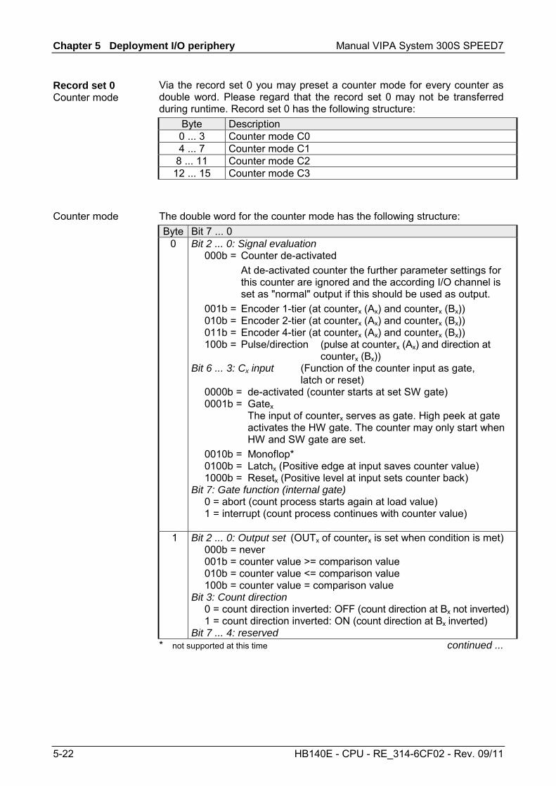
Chapter 5 Deployment I/O periphery Manual VIPA System 300S SPEED7
5-22 HB140E - CPU - RE_314-6CF02 - Rev. 09/11
Via the record set 0 you may preset a counter mode for every counter as double word. Please regard that the record set 0 may not be transferred during runtime. Record set 0 has the following structure:
Byte Description 0 ... 3 Counter mode C0 4 ... 7 Counter mode C1
8 ... 11 Counter mode C2 12 ... 15 Counter mode C3
The double word for the counter mode has the following structure: Byte Bit 7 ... 0
0 Bit 2 ... 0: Signal evaluation 000b = Counter de-activated At de-activated counter the further parameter settings for
this counter are ignored and the according I/O channel is set as "normal" output if this should be used as output.
001b = Encoder 1-tier (at counterx (Ax) and counterx (Bx)) 010b = Encoder 2-tier (at counterx (Ax) and counterx (Bx)) 011b = Encoder 4-tier (at counterx (Ax) and counterx (Bx)) 100b = Pulse/direction (pulse at counterx (Ax) and direction at
counterx (Bx)) Bit 6 ... 3: Cx input (Function of the counter input as gate,
latch or reset) 0000b = de-activated (counter starts at set SW gate) 0001b = Gatex The input of counterx serves as gate. High peek at gate
activates the HW gate. The counter may only start when HW and SW gate are set.
0010b = Monoflop* 0100b = Latchx (Positive edge at input saves counter value) 1000b = Resetx (Positive level at input sets counter back) Bit 7: Gate function (internal gate) 0 = abort (count process starts again at load value) 1 = interrupt (count process continues with counter value)
1 Bit 2 ... 0: Output set (OUTx of counterx is set when condition is met) 000b = never 001b = counter value >= comparison value 010b = counter value <= comparison value 100b = counter value = comparison value Bit 3: Count direction 0 = count direction inverted: OFF (count direction at Bx not inverted) 1 = count direction inverted: ON (count direction at Bx inverted) Bit 7 ... 4: reserved
* not supported at this time continued ...
Record set 0 Counter mode
Counter mode

Manual VIPA System 300S SPEED7 Chapter 5 Deployment I/O periphery
HB140E - CPU - RE_314-6CF02 - Rev. 09/11 5-23
... continue Byte Bit 7 ... 0
2 Bit 5 ... 0: Counter function 000000b = Count endless 000001b = Once: forward 000010b = Once: backwards 000100b = Once: no main direction 001000b = Periodic: forward 010000b = Periodic: backwards 100000b = Periodic: no main direction More details at "Counter - Functions" below. Bit 7 ... 6: Cx In-/Output (Function of the counter I/O as OUT,
Latch or Reset) 00b = O: OUTx (at comparison function) 01b = I: Latchx (rising edge saves counter value) 10b = I: Resetx (positive level resets counter)
3 Bit 5 ... 0: Interrupt behavior Bit 0: Proc. interrupt HW gate open Bit 1: Proc. interrupt HW gate closed Bit 2: Proc. interrupt overflow Bit 3: Proc. interrupt underrun Bit 4: Proc. interrupt comparison value Bit 5: Proc. interrupt end value By setting the Bits you may activate the wanted process interrupts. Bit 7 ... 6: reserved
This record set activates res. de-activates the diagnostic function. A diagnostic interrupt occurs when during a process interrupt execution another process interrupt is initialized for the same event. The record set has the following structure: Byte Bit 15 ... 0 0...1 Bit 15 ... 0: Diagnostic interrupt
0000h = de-activated 0001h = activated
2...3 Bit 15 ... 0: reserved
Record set 7Fh Diagnostic interrupt

Chapter 5 Deployment I/O periphery Manual VIPA System 300S SPEED7
5-24 HB140E - CPU - RE_314-6CF02 - Rev. 09/11
Via this record set you may activate a process interrupt for I+0.0 ... I+1.7 and define for which edge type of the input signal a process interrupt is thrown. The record set has the following structure:
Byte Bit 7 ... 0 0 Bit 1 ... 0: Edge selection I+0.0
00b = de-activated 01b = Process interrupt at rising edge 10b = Process interrupt at falling edge 11b = Process interrupt at rising and falling edge Bit 7 ... 2: reserved
... ... 15 Bit 1 ... 0: Edge selection I+1.7
00b = de-activated 01b = Process interrupt at rising edge 10b = Process interrupt at falling edge 11b = Process interrupt at rising and falling edge Bit 7 ... 2: reserved
This record set allows you to preset an input filter in steps of 2.56µs steps for I+0.0 ... I+1.7. By preceding a filter you define how long an input signal must be present before it is recognized as "1" signal. With the help of filters you may e.g. filter signal peaks at a blurred input signal. The entry happens as a factor of 2.56µs and is within the range 1 ... 16000 i.e. 2.56µs ... 40.96ms. The record set has the following structure:
Byte Bit 15 ... 0 0 ... 1 Bit 15 ... 0: Input filter I+0.0 in 2.56µs 2 ... 3 Bit 15 ... 0: Input filter I+0.1 in 2.56µs 4 ... 5 Bit 15 ... 0: Input filter I+0.2 in 2.56µs
... ... 30 ... 31 Bit 15 ... 0: Input filter I+1.7 in 2.56µs
Each of the following counter parameters has an assigned record set depending on the counter number. Additionally for every counter the parameter are summoned in one record set. The record sets have the same structure for every counter. Please refer to the following table for the structure and the according record set number assignment. The record set has the following structure: Count. 0
87h Count. 1
8Dh Count. 2
93h Count. 3
99h Type Function
82h 88h 8Eh 94h Double word Comparison value 83h 89h 8Fh 95h Double word Load value 84h 8Ah 90h 96h Double word End value 85h 8Bh 91h 97h Word Hysteresis 86h 8Ch 92h 98h Word Pulse
Record set 80h Edge selection
Record set 81h Input filter
Record set 82 ... 99h Counter parameter

Manual VIPA System 300S SPEED7 Chapter 5 Deployment I/O periphery
HB140E - CPU - RE_314-6CF02 - Rev. 09/11 5-25
Via the parameterization you may preset a comparison value that may influence the counter output res. throw a process interrupt when compared with the recent counter value. The behavior of the output res. the process interrupt has to be set via the record set 0. You may define a main counting direction for every counter via the parameterization. If "none" or "endless" is chosen, the complete counting range is available: Counter limits Valid value range Lower count limit - 2 147 483 648 (-231) Upper count limit + 2 147 483 647 (231-1)
Otherwise you may set an upper and a lower limit by setting a load value as start and an end value. The hysteresis serves the avoidance of many toggle processes of the output and the interrupt, if the counter value is in the range of the comparison value. You may set a range of 0 to 255. The settings 0 and 1 deactivate the hysteresis. The hysteresis influences zero run, comparison, over- and underflow. The pulse duration tells for what time the output is set when the parameterized comparison criterion is reached res. overstepped. The pulse duration can be set in steps of 2.048ms between 0 and 522.24ms. If the pulse duration = 0, the output is set active until the comparison condition is not longer fulfilled.
Note! More details are under "Counter – Additional functions" below!
A register can be preset using record set (9A+x)h. The current counter value is replaced by the register value by setting bit 5 of the output status word without any influence to the load value. Using this record set you can de-activate the digital res. analog part. If a part is de-activated the corresponding area of the process image is just reserved. The record set has the following structure:
Byte Bit 15 ... 0 0...1 Bit 15 ... 0: Module selection
0000h = Digital / analog part activated (default) 0001h = Digital part de-activated 0002h = Analog part de-activated
… Continue Record set 82 … 99h
Comparison value
Load value, end value
Hysteresis
Pulse (Pulse duration)
Datensatz 9A ... 9Dh Set counter value temporary
Record set 9Eh Module selection

Chapter 5 Deployment I/O periphery Manual VIPA System 300S SPEED7
5-26 HB140E - CPU - RE_314-6CF02 - Rev. 09/11
Counter - Functions
You may count forward and backwards and choose between the following counter functions: • Count endless, e.g. distance measuring with incremental encoder • Count once, e.g. count to a maximum limit • Count periodic, e.g. count with repeated counter process In the operating modes "Count once" and "Count periodic" you may define a counter range as start and end value via the parameterization. For every counter additional parameterizable functions are available like gate function, latch function, comparison, hysteresis and process interrupt.
Via the parameterization you have the opportunity to define a main counting direction for every counter. If "none" is chosen, the complete counting range is available: Valid value range Lower count limit -2 147 483 648 (-231) Upper count limit +2 147 483 647 (231-1)
Main counting direction forward Upper restriction of the count range. The counter counts 0 res. load value in positive direction until the parameterized end value –1 and jumps then back to the load value with the next following encoder pulse. Main counting direction backwards Lower restriction of the count range. The counter counts from the parameterized start- res. load value in negative direction to the parameterized end value +1 and jumps then back to the start value with the next following encoder pulse.
Abort count process The count process starts after closing and restart of the gate beginning with the load value. Interrupt count process The count process continuous after closing and restart of the gate beginning with the last recent counter value.
Overview
Main counting direction
Abort - interrupt

Manual VIPA System 300S SPEED7 Chapter 5 Deployment I/O periphery
HB140E - CPU - RE_314-6CF02 - Rev. 09/11 5-27
In this operating mode, the counter counts from 0 res. from the load value. When the counter counts forward and reaches the upper count limit and another counting pulse in positive direction arrives, it jumps to the lower count limit and counts from there on. When the counter counts backwards and reaches the lower count limit and another counting pulse in negative direction arrives, it jumps to the upper count limit and counts from there on. The count limits are set to the maximum count range. Valid value range Lower count limit -2 147 483 648 (-231) Upper count limit +2 147 483 647 (231-1)
load value
gate start
time
gate stopp gate start
counter value
Count Continuously

Chapter 5 Deployment I/O periphery Manual VIPA System 300S SPEED7
5-28 HB140E - CPU - RE_314-6CF02 - Rev. 09/11
No main counting direction • The counter counts once starting with the load value. • You may count forward or backwards. • The count limits are set to the maximum count range. • At over- or underrun at the count limits, the counter jumps to the
according other count limit and the gate is automatically closed. • To restart the count process, you must create a positive edge of the
gate. • At interrupting gate control, the count process continuous with the
last recent counter value. • At aborting gate control, the counter starts with the load value.
Valid value range Lower count limit -2 147 483 648 (-231) Upper count limit +2 147 483 647 (231-1)
Interrupting gate control:
end value
lowercounter limit
load value
0
gate start
overflow
underflow
time
counter value
gate stop Aborting gate control:
uppercounter limit
load value
0
gate start time
counter value
gate stopautomatically
gate start
end value
gate stopautomatically
Count Once
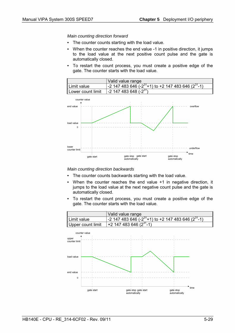
Manual VIPA System 300S SPEED7 Chapter 5 Deployment I/O periphery
HB140E - CPU - RE_314-6CF02 - Rev. 09/11 5-29
Main counting direction forward • The counter counts starting with the load value. • When the counter reaches the end value -1 in positive direction, it jumps
to the load value at the next positive count pulse and the gate is automatically closed.
• To restart the count process, you must create a positive edge of the gate. The counter starts with the load value.
Valid value range Limit value -2 147 483 646 (-231+1) to +2 147 483 646 (231-1) Lower count limit -2 147 483 648 (-231)
end value
lowercounter limit
load value
0
overflow
underflow
time
counter value
gate stopautomatically
gate stopautomatically
gate start gate start
Main counting direction backwards • The counter counts backwards starting with the load value. • When the counter reaches the end value +1 in negative direction, it
jumps to the load value at the next negative count pulse and the gate is automatically closed.
• To restart the count process, you must create a positive edge of the gate. The counter starts with the load value.
Valid value range Limit value -2 147 483 646 (-231+1) to +2 147 483 646 (231-1) Upper count limit +2 147 483 646 (231-1)
uppercounter limit
load value
0
gate start time
counter value
gate stopautomatically
gate start
end value
gate stopautomatically

Chapter 5 Deployment I/O periphery Manual VIPA System 300S SPEED7
5-30 HB140E - CPU - RE_314-6CF02 - Rev. 09/11
No main counting direction • The counter counts forward or backwards starting with the load value. • At over- or underrun at the count limits, the counter jumps to the
according other count limit and counts from there on. • The count limits are set to the maximum count range.
Valid value range Lower count limit -2 147 483 648 (-231) Upper count limit +2 147 483 647 (231-1)
uppercounter limit
load value
0
gate start time
counter value
gate stop
lowercounter limit
overflow
underflow
zero-crossing
Main counting direction forward • The counter counts forward starting with the load value • When the counter reaches the end value –1 in positive direction, it
jumps to the load value at the next positive count pulse.
Valid value range Limit value -2 147 483 647 (-231+1) to +2 147 483 647 (231-1) Lower count limit -2 147 483 648 (-231)
end value
lowercounter limit
load value
0
gate start
overflow
underflow
time
counter value
gate stop
Count Periodically

Manual VIPA System 300S SPEED7 Chapter 5 Deployment I/O periphery
HB140E - CPU - RE_314-6CF02 - Rev. 09/11 5-31
Main counting direction backwards • The counter counts backwards starting with the load value • When the counter reaches the end value+1 in negative direction, it
jumps to the load value at the next negative count pulse. • You may exceed the upper count limit. Valid value range Limit value -2 147 483 647 (-231+1) to +2 147 483 647 (231-2) Upper count limit +2 147 483 647 (231-1)
uppercounter limit
load value
0
gate start time
counter value
gate stop
end value

Chapter 5 Deployment I/O periphery Manual VIPA System 300S SPEED7
5-32 HB140E - CPU - RE_314-6CF02 - Rev. 09/11
Counter - Additional functions
The following additional functions may be set via the parameterization for every counter: • Gate function
The gate function serves the start, stop and interrupt of a count function. • Latch function
A positive edge at the digital input "Latch" stores the recent counter value in the latch register.
• Comparison You may set a comparison value that activates res. de-activates a digital output res. releases a process interrupt depending on the counter value.
• Hysteresis The setting of a hysteresis avoids for example a high output toggling when the value of an encoder signal shifts around a comparison value.
The illustration shows how the additional functions influence the counting behavior. The following pages describe these functions in detail:
HW gate
Internal gate
SW gate
Pulse evaluation
Pulse/Track A Direction/Track B
Comparison value Counter value Latch
Latch
Load value
Comparision
Hysteresis
Output
Processinterrupt
Release
Overview
Schematic structure

Manual VIPA System 300S SPEED7 Chapter 5 Deployment I/O periphery
HB140E - CPU - RE_314-6CF02 - Rev. 09/11 5-33
The activation res. de-activation of a counter happens via an internal gate (I-gate). The I-gate consists of a software gate (SW-gate) and a Hardware gate (HW-gate). The SW-gate is opened (activated) via your user application by setting the output status bit 2 for the according counter. The SW-gate is closed (deactivated) by setting the output status bit 10. The HW-gate is controlled via the concerning "Gate" input. The parame-terization allows you to de-activate the consideration of the HW-gate so that the counter activation can take place only via the SW-gate. The following states influence the I-gate:
SW-gate HW-gate influences I-gate 0 with positive edge 0 1 with positive edge 1
with positive edge 1 1 with positive edge 0 0 with positive edge de-activated 1
Gate function abort and interrupt The parameterization defines if the gate interrupts or aborts the counter process. • At abort function the counter starts counting with the load value after
gate restart.
load value
gate start time
counter value
gate stopp gate start • At interrupt function, the counter starts counting with the last recent
counter value after gate restart.
load value
gate start
time
gate stopp gate start
counter value
Gate function

Chapter 5 Deployment I/O periphery Manual VIPA System 300S SPEED7
5-34 HB140E - CPU - RE_314-6CF02 - Rev. 09/11
Gate control via SW gate, aborting (Parameterization: record set 0, Byte 0, Bit 7 ... 3 = 00000b)
SW gate HW gate Reaction Counter positive edge de-activated Restart with load value
Gate control via SW gate, interrupting (Parameterization: record set 0, Byte 0, Bit 7 ... 3 = 10000b)
SW gate HW gate Reaction Counter positive edge de-activated Continue
Gate control via SW/HW gate, aborting (Parameterization: record set 0, Byte 0, Bit 7 ... 3 = 00001b)
SW gate HW gate Reaction Counter positive edge 1 Continue
1 positive edge Restart with load value Gate control via SW/HW gate, interrupting (Parameterization: record set 0, Byte 0, Bit 7 ... 3 = 10001b)
SW gate HW gate Reaction Counter positive edge 1 Continue
1 positive edge Continue
Gate control via SW/HW gate, operating mode "Count once" If the internal gate has been closed automatically it may only be opened again under the following conditions:
SW gate HW gate Reaction I gate 1 positive edge 1
positive edge (after positive edge at
HW gate)
positive edge 1
Gate control abort, interruption
Gate control "Count once"

Manual VIPA System 300S SPEED7 Chapter 5 Deployment I/O periphery
HB140E - CPU - RE_314-6CF02 - Rev. 09/11 5-35
As soon as during a count process a positive edge is recognized at the "Latch" input of a counter, the recent counter value is stored in the according latch register. You may access the latch register via the "input image". For this set Bit 15 of the output status word. At a new latch value additionally Bit 13 is set in the input status word. By setting Bit 15 in the output status word you may read the recent latch value of the according counter and reset the Bit 13 of the input status word.
You pre-define the behavior of the counter output via the parameterization: • output never switches • output switch when counter value ≥ comparison value • output switch when counter value ≤ comparison value • output switch at comparison value Output never switches The output is set as normal output. Output switch when counter value ≥ comparison value The output remains set as long as the counter value is higher or equal comparison value. Output switch when counter value ≤ comparison value The output remains set as long as the counter value is lower or equal comparison value. Pulse at comparison value When the counter reaches the comparison value the output is set for the parameterized pulse duration. If the pulse duration = 0 the output is set until the comparison condition is no longer met. When you've set a main counting direction the output is only set at reaching the comparison value from the main counting direction. Pulse duration The pulse duration defines how long the output is set. it may be preset in steps of 2.048ms between 0 and 522.24ms. The pulse duration starts with the setting of the according digital output. The inaccuracy of the pulse duration is less than 2.048ms. There is no past triggering of the pulse duration when the comparison value has been left and reached again during pulse output.
Latch function
Comparison

Chapter 5 Deployment I/O periphery Manual VIPA System 300S SPEED7
5-36 HB140E - CPU - RE_314-6CF02 - Rev. 09/11
The hysteresis serves e.g. the avoidance of many toggle processes of the output and the interrupt, if the counter value is in the range of the comparison value. You may set a range of 0 to 255. The settings 0 and 1 deactivate the hysteresis. The hysteresis influences the zero run, over- and underflow. An activated hysteresis remains active after a change. The new hysteresis range is taken over at the next reach of the comparison value. The following pictures illustrate the output behavior for hysteresis 0 and hysteresis 3 for the according conditions:
Effect at counter value ≥ comparison value
876543210
Comparison value
Hysteresis
Output:Hysteresis = 0
Hysteresis = 3
Counter value
1
2
3 4 5 67
1 Counter value ≥ comparison value → output is set and hysteresis activated
2 Leave hysteresis range → output is reset
3 Counter value ≥ comparison value → output is set and hysteresis activated
4 Leave hysteresis range, output remains set for counter value ≥ comparison value
5 Counter value < comparison value and hysteresis active → output is reset
6 Counter value ≥ comparison value → output is not set for hysteresis active
7 Leave hysteresis range, output remains set for counter value ≥ comparison value
With reaching the comparison condition the hysteresis gets active. At active hysteresis the comparison result remains unchanged until the counter value leaves the set hysteresis range. After leaving the hysteresis range a new hysteresis is only activated with again reaching the comparison conditions.
Hysteresis

Manual VIPA System 300S SPEED7 Chapter 5 Deployment I/O periphery
HB140E - CPU - RE_314-6CF02 - Rev. 09/11 5-37
Effect at pulse at comparison value with pulse duration Zero
876543210
Comparison value
Hysteresis
Output:Hysteresis = 0
Hysteresis = 3
Counter value
1
2
3 4 5 67
1 Counter value = comparison value → output is set and hysteresis activated
2 Leave hysteresis range → output is reset and counter value < comparison value
3 Counter value = comparison value → output is set and hysteresis activated
4 Output is reset for leaving hysteresis range and counter value > comparison value
5 Counter value = comparison value → output is set and hysteresis activated
6 Counter value = comparison value and hysteresis active → output remains set
7 Leave hysteresis range and counter value > comparison value → output is reset With reaching the comparison condition the hysteresis gets active. At active hysteresis the comparison result remains unchanged until the counter value leaves the set hysteresis range. After leaving the hysteresis range a new hysteresis is only activated with again reaching the comparison conditions.

Chapter 5 Deployment I/O periphery Manual VIPA System 300S SPEED7
5-38 HB140E - CPU - RE_314-6CF02 - Rev. 09/11
Effect at pulse at comparison value with pulse duration not zero
876543210
Comparison value
Hysteresis
Output:Hysteresis = 0
Hysteresis = 3
Counter value
1
2
3 4 5 67
1 Counter value = comparison value → pulse of the parameterized duration is put out, the hysteresis is activated and the counting direction stored
2 Leaving the hysteresis range contrary to the stored counting direction → pulse of the parameterized duration is put out, the hysteresis is de-activated
3 Counter value = comparison value → pulse of the parameterized duration is put out, the hysteresis is activated and the counting direction stored
4 Leaving the hysteresis range without changing counting direction → hysteresis is de-activated
5 Counter value = comparison value → pulse of the parameterized duration is put out, the hysteresis is activated and the counting direction stored
6 Counter value = comparison value and hysteresis active → no pulse
7 Leaving the hysteresis range contrary to the stored counting direction → pulse of the parameterized duration is put out, the hysteresis is de-activated
With reaching the comparison condition the hysteresis gets active and a pulse of the parameterized duration is put out. As long as the counter value is within the hysteresis range, no other pulse is put out. With activating the hysteresis the counting direction is stored in the CPU. If the counter value leaves the hysteresis range contrary to the stored counting direction, a pulse of the parameterized duration is put out. Leaving the hysteresis range without direction change, no pulse is put out.

Manual VIPA System 300S SPEED7 Chapter 5 Deployment I/O periphery
HB140E - CPU - RE_314-6CF02 - Rev. 09/11 5-39
Counter - Diagnostic and interrupt
The parameterization allows you to define the following trigger for a process interrupt that may initialize a diagnostic interrupt: • Status changes at an input • Status changes at the HW-gate • Over- res. underflow • Reaching a comparison value A process interrupt causes a call of the OB 40. Within the OB 40 you may find the logical basic address of the module that initialized the process interrupt by using the Local word 6. More detailed information about the initializing event is to find in the local double word 8. The local double word 8 of the OB 40 has the following structure:
Local byte Bit 7 ... 0 8 Bit 0: Edge at I+0.0
Bit 1: Edge at I+0.1 Bit 2: Edge at I+0.2 Bit 3: Edge at I+0.3 Bit 4: Edge at I+0.4 Bit 5: Edge at I+0.5 Bit 6: Edge at I+0.6 Bit 7: Edge at I+0.7
9 Bit 0: Edge at I+1.0 Bit 1: Edge at I+1.1 Bit 2: Edge at I+1.2 Bit 3: Edge at I+1.3 Bit 4: Edge at I+1.4 Bit 5: Edge at I+1.5 Bit 6: Edge at I+1.6 Bit 7: Edge at I+1.7
10 Bit 0: Gate counter 0 open (activated) Bit 1: Gate counter 0 closed Bit 2: Over-/underflow/end value counter 0 Bit 3: Counter 0 reached comparison value Bit 4: Gate counter 1 open (activated) Bit 5: Gate counter 1 closed Bit 6: Over-/underflow/ end value counter 1 Bit 7: Counter 1 reached comparison value
11 Bit 0: Gate counter 2 open (activated) Bit 1: Gate counter 2 closed Bit 2: Over-/underflow/end value counter 2 Bit 3: Counter 2 reached comparison value Bit 4: Gate counter 3 open (activated) Bit 5: Gate counter 3 closed Bit 6: Over-/underflow/end value counter 3 Bit 7: Counter 3 reached comparison value
Outline
Process interrupt
Local double word 8 of the OB 40

Chapter 5 Deployment I/O periphery Manual VIPA System 300S SPEED7
5-40 HB140E - CPU - RE_314-6CF02 - Rev. 09/11
Via the parameterization (record set 7Fh) you may activate a global diagnostic interrupt for the analog and digital part. A diagnostic interrupt occurs when during a process interrupt execution in OB 40 another process interrupt is thrown for the same event. The initialization of a diagnostic interrupt interrupts the recent process interrupt execution in OB 40 and branches in OB 82 to diagnostic interrupt processingincoming. If during the diagnostic interrupt processing other events are occurring at other channels that may also cause a process res. diagnostic interrupt, these are interim stored. After the end of the diagnostic interrupt processing at first all interim stored diagnostic interrupts are processed in the sequence of their occurrence and then all process interrupts. If a channel where currently a diagnostic interruptincoming is processed res. interim stored initializes further process interrupts, these get lost. When a process interrupt for which a diagnostic interruptincoming has been released is ready, the diagnostic interrupt processing is called again as diagnostic interruptgoing. All events of a channel between diagnostic interruptincoming and diagnostic interruptgoing are not stored and get lost. Within this time window (1st diagnostic interruptincoming until last diagnostic interruptgoing) the SF-LED of the CPU is on. Additionally for every diagnostic interruptincoming/going an entry in the diagnostic buffer of the CPU occurs.
Process interrupt:
OB40:without diagnostic interrupt:
OB40:
OB82:
OB40_8
OB82_8 OB82_3 OB82_8 OB82_3
Fast memory buffer Proz (FIFO):
OB40_3 OB40_6 OB40_14
3 36
3614
614
14
Fast memory buffer (FIFO): 3 6 14
OB40_8 OB40_3 OB40_6 OB40_14
with diagnostic interrupt:
lost lost
3
Fast memory buffer Diag (FIFO): 38
14
incoming outgoing outgoing
8
Input channel: 8 3 8 3 6 14 3
8
8
8 3 614
OB40_3
lost
incoming
8
3 8 3
33 6 6
Diagnostic interrupt
Example

Manual VIPA System 300S SPEED7 Chapter 5 Deployment I/O periphery
HB140E - CPU - RE_314-6CF02 - Rev. 09/11 5-41
Every OB 82 call causes an entry in the diagnostic buffer of the CPU containing error cause and module address. By using the SFC 59 you may read the diagnostic bytes. At de-activated diagnostic interrupt you have access to the last recent diagnostic event. If you've activated the diagnostic function in your hardware configuration, the contents of record set 0 are already in the local double word 8 when calling the OB 82. The SFC 59 allows you to also read the record set 1 that contains additional information. After leaving the OB 82 a clear assignment of the data to the last diagnostic interrupt is not longer possible. The record sets of the diagnostic range have the following structure:
Byte Bit 7 ... 0 0 Bit 0: set at module failure
Bit 1: 0 (fix) Bit 2: set at external error Bit 3: set at channel error Bit 4: set when external auxiliary supply is missing Bit 7 ... 5: 0 (fix)
1 Bit 3 ... 0: Module class 0101b: Analog 1111b: Digital Bit 4: Channel information present Bit 7 ... 5: 0 (fix)
2 Bit 3 ... 0: 0 (fix) Bit 4: Failure module internal supply voltage (output overload) Bit 7 ... 5: 0 (fix)
3 Bit 5 ... 0: 0 (fix) Bit 6: Process interrupt lost Bit 7: 0 (fix)
After the removing error a diagnostic messagegoing takes place if the diagnostic interrupt release is still active.
Byte Bit 7 ... 0 0 Bit 0: set at module failure
Bit 1: 0 (fix) Bit 2: set at external error Bit 3: set at channel error Bit 4: set when external auxiliary supply is missing Bit 7 ... 5: 0 (fix)
1 Bit 3 ... 0: Module class 0101b: Analog module 1111b: Digital Bit 4: Channel information present Bit 7 ... 5: 0 (fix)
2 00h (fix) 3 00h (fix)
Diagnostic interrupt processing
Record set 0 Diagnosticincoming
Record set 0 Diagnosticgoing

Chapter 5 Deployment I/O periphery Manual VIPA System 300S SPEED7
5-42 HB140E - CPU - RE_314-6CF02 - Rev. 09/11
The record set 1 contains the 4byte of the record set 0 and additionally 12byte module specific diagnostic data. The diagnostic bytes have the following assignment:
Byte Bit 7 ... 0 0 ... 3 Contents record set 0 (see page before)
4 Bit 6 ... 0: channel type (here 70h) 70h: Digital input 71h: Analog input 72h: Digital output 73h: Analog output 74h: Analog in-/output Bit 7: More channel types present 0: no 1: yes
5 Number of diagnostic bits per channel (here 08h) 6 Number of channels of a module (here 08h) 7 Bit 0: Error in channel group 0 (I+0.0 ... I+0.3)
Bit 1: Error in channel group 1 (I+0.4 ... I+0.7) Bit 2: Error in channel group 2 (I+1.0 ... I+1.3) Bit 3: Error in channel group 3 (I+1.4 ... I+I.7) Bit 4: Error in channel group 4 (Counter 0) Bit 5: Error in channel group 5 (Counter 1) Bit 6: Error in channel group 6 (Counter 2) Bit 7: Error in channel group 7 (Counter 3)
8 Diagnostic interrupt due to process interrupt lost at... Bit 0: ... input I+0.0 Bit 1: 0 (fix) Bit 2: ... input I+0.1 Bit 3: 0 (fix) Bit 4: ... input I+0.2 Bit 5: 0 (fix) Bit 6: ... input I+0.3 Bit 7: 0 (fix)
9 Diagnostic interrupt due to process interrupt lost at... Bit 0: ... input I+0.4 Bit 1: 0 (fix) Bit 2: ... input I+0.5 Bit 3: 0 (fix) Bit 4: ... input I+0.6 Bit 5: 0 (fix) Bit 6: ... input I+0.7 Bit 7: 0 (fix)
10 Diagnostic interrupt due to process interrupt lost at... Bit 0: ... input I+1.0 Bit 1: 0 (fix) Bit 2: ... input I+1.1 Bit 3: 0 (fix) Bit 4: ... input I+1.2 Bit 5: 0 (fix) Bit 6: ... input I+1.3 Bit 7: 0 (fix)
continued ...
Diagnostic Record set 1 (Byte 0 ... 15)
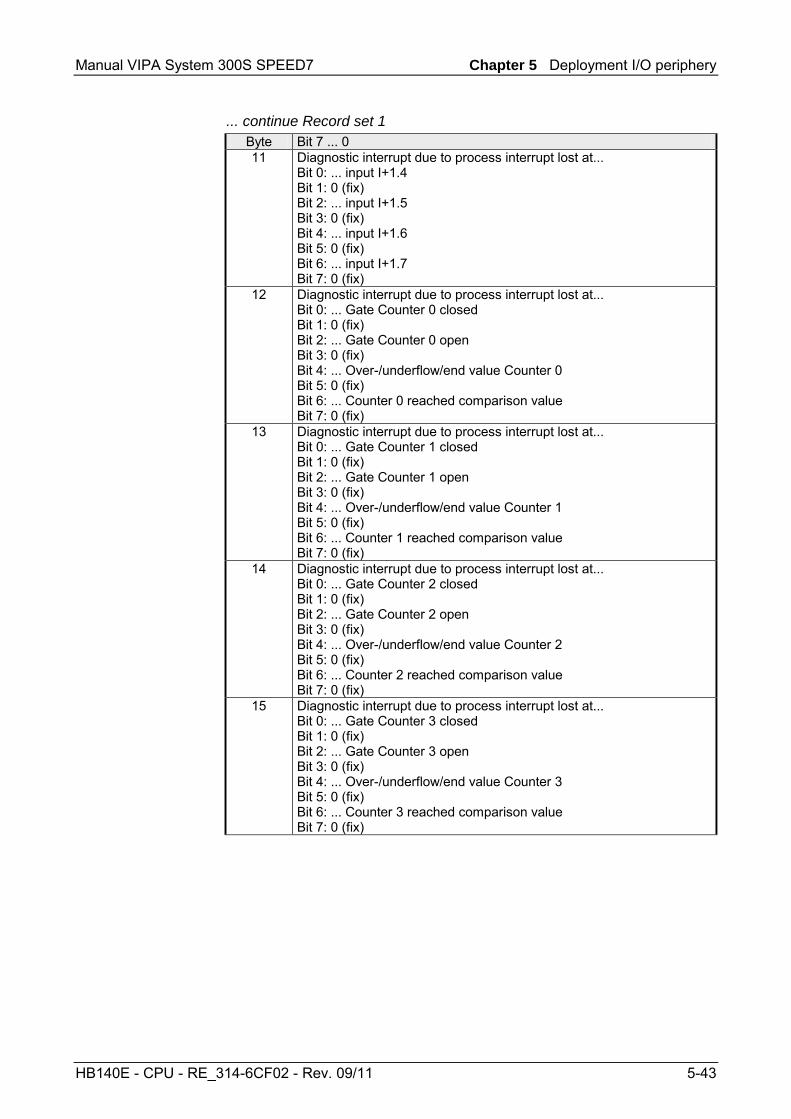
Manual VIPA System 300S SPEED7 Chapter 5 Deployment I/O periphery
HB140E - CPU - RE_314-6CF02 - Rev. 09/11 5-43
... continue Record set 1 Byte Bit 7 ... 0 11 Diagnostic interrupt due to process interrupt lost at...
Bit 0: ... input I+1.4 Bit 1: 0 (fix) Bit 2: ... input I+1.5 Bit 3: 0 (fix) Bit 4: ... input I+1.6 Bit 5: 0 (fix) Bit 6: ... input I+1.7 Bit 7: 0 (fix)
12 Diagnostic interrupt due to process interrupt lost at... Bit 0: ... Gate Counter 0 closed Bit 1: 0 (fix) Bit 2: ... Gate Counter 0 open Bit 3: 0 (fix) Bit 4: ... Over-/underflow/end value Counter 0 Bit 5: 0 (fix) Bit 6: ... Counter 0 reached comparison value Bit 7: 0 (fix)
13 Diagnostic interrupt due to process interrupt lost at... Bit 0: ... Gate Counter 1 closed Bit 1: 0 (fix) Bit 2: ... Gate Counter 1 open Bit 3: 0 (fix) Bit 4: ... Over-/underflow/end value Counter 1 Bit 5: 0 (fix) Bit 6: ... Counter 1 reached comparison value Bit 7: 0 (fix)
14 Diagnostic interrupt due to process interrupt lost at... Bit 0: ... Gate Counter 2 closed Bit 1: 0 (fix) Bit 2: ... Gate Counter 2 open Bit 3: 0 (fix) Bit 4: ... Over-/underflow/end value Counter 2 Bit 5: 0 (fix) Bit 6: ... Counter 2 reached comparison value Bit 7: 0 (fix)
15 Diagnostic interrupt due to process interrupt lost at... Bit 0: ... Gate Counter 3 closed Bit 1: 0 (fix) Bit 2: ... Gate Counter 3 open Bit 3: 0 (fix) Bit 4: ... Over-/underflow/end value Counter 3 Bit 5: 0 (fix) Bit 6: ... Counter 3 reached comparison value Bit 7: 0 (fix)

Chapter 5 Deployment I/O periphery Manual VIPA System 300S SPEED7
5-44 HB140E - CPU - RE_314-6CF02 - Rev. 09/11

Manual VIPA System 300S SPEED7 Chapter 6 Deployment PtP communication
HB140E - CPU - RE_314-6CF02 - Rev. 09/11 6-1
Chapter 6 Deployment PtP communication
Content of this chapter is the employment of the RS485 slot for serial PtP communication. Here you’ll find all information about the protocols, the activation and project engineering of the interface which are necessary for the serial communication using the RS485 interface.
Topic Page Chapter 6 Deployment PtP communication.................................... 6-1
Fast introduction................................................................................... 6-2 Protocols and procedures..................................................................... 6-3 Deployment of RS485 interface for PtP ................................................ 6-7 Principle of the data transfer................................................................. 6-9 Parameterization ................................................................................ 6-10 Communication .................................................................................. 6-13
Overview
Content

Chapter 6 Deployment PtP communication Manual VIPA System 300S SPEED7
6-2 HB140E - CPU - RE_314-6CF02 - Rev. 09/11
Fast introduction
Via a hardware configuration you may de-activate the Profibus part integrated to the SPEED7 CPU and thus release the RS485 interface for PtP (point-to-point) communication. The RS485 interface supports in PtP operation the serial process connection to different source res. destination systems.
The protocols res. procedures ASCII, STX/ETX, 3964R, USS and Modbus are supported.
Per default, every CPU uses the RS485 interface for Profibus communication. A hardware configuration allows you to switch the RS485 interface to point-to-point operation using Object properties and the parameter "Function RS485".
The parameterization of the serial interface happens during runtime using the SFC 216 (SER_CFG). For this you have to store the parameters in a DB for all protocols except ASCII.
The SFCs are controlling the communication. Send takes place via SFC 217 (SER_SND) and receive via SFC 218 (SER_RCV). The repeated call of the SFC 217 SER_SND delivers a return value for 3964R, USS and Modbus via RetVal that contains, among other things, recent information about the acknowledgement of the partner station. The protocols USS and Modbus allow to evaluate the receipt telegram by calling the SFC 218 SER_RCV after SER_SND. The SFCs are included in the consignment of the CPU.
The following SFCs are used for the serial communication:
SFC Description SFC 216 SER_CFG RS485 parameterize SFC 217 SER_SND RS485 send SFC 218 SER_RCV RS485 receive
General
Protocols
Switch of RS485 for ptp operation
Parameterization
Communication
Overview SFCs for serial communication

Manual VIPA System 300S SPEED7 Chapter 6 Deployment PtP communication
HB140E - CPU - RE_314-6CF02 - Rev. 09/11 6-3
Protocols and procedures
The CPU supports the following protocols and procedures: • ASCII communication • STX/ETX • 3964R • USS • Modbus
ASCII data communication is one of the simple forms of data exchange. Incoming characters are transferred 1 to 1. At ASCII, with every cycle the read-SFC is used to store the data that is in the buffer at request time in a parameterized receive data block. If a telegram is spread over various cycles, the data is overwritten. There is no reception acknowledgement. The communication procedure has to be controlled by the concerning user application. An according Receive_ASCII-FB is to find at ftp.vipa.de.
STX/ETX is a simple protocol with start and end ID, where STX stands for Start of Text and ETX for End of Text. The STX/ETX procedure is suitable for the transfer of ASCII characters. It does not use block checks (BCC). Any data transferred from the periphery must be preceded by a Start followed by the data characters and the end character. Depending of the byte width the following ASCII characters can be transferred: 5Bit: not allowed: 6Bit: 20...3Fh, 7Bit: 20...7Fh, 8Bit: 20...FFh. The effective data, which includes all the characters between Start and End are transferred to the PLC when the End has been received. When data is send from the PLC to a peripheral device, any user data is handed to the SFC 217 (SER_SND) and is transferred with added Start- and End-ID to the communication partner. Message structure:
STX2 Z1 Z2 Zn ETX1 ETX2
ZVZ
STX1
You may define up to 2 Start- and End-IDs. You may work with 1, 2 or no Start- and with 1, 2 or no End-ID. As Start- res. End-ID all Hex values from 01h to 1Fh are permissible. Characters above 1Fh are ignored. In the user data, characters below 20h are not allowed and may cause errors. The number of Start- and End-IDs may be different (1 Start, 2 End res. 2 Start, 1 End or other combinations). If no End-ID is defined, all read characters are transferred to the PLC after a parameterizable character delay time (Timeout).
Overview
ASCII
STX/ETX

Chapter 6 Deployment PtP communication Manual VIPA System 300S SPEED7
6-4 HB140E - CPU - RE_314-6CF02 - Rev. 09/11
The 3964R procedure controls the data transfer of a point-to-point link between the CPU and a communication partner. The procedure adds control characters to the message data during data transfer. These control characters may be used by the communication partner to verify the complete and error free receipt. The procedure employs the following control characters: • STX Start of Text • DLE Data Link Escape • ETX End of Text • BCC Block Check Character • NAK Negative Acknowledge
STX
DLEMessage-data
DLE
ETX
BCC
Monitor delayed acknowledgmentDLE
Monitor delayed acknowledgment
Active partner Passive partner
You may transfer a maximum of 255byte per message.
Note! When a DLE is transferred as part of the information it is repeated to distinguish between data characters and DLE control characters that are used to establish and to terminate the connection (DLE duplication). The DLE duplication is reversed in the receiving station. The 3964R procedure requires that a lower priority is assigned to the communication partner. When communication partners issue simultaneous send commands, the station with the lower priority will delay its send command.
3964R
Procedure
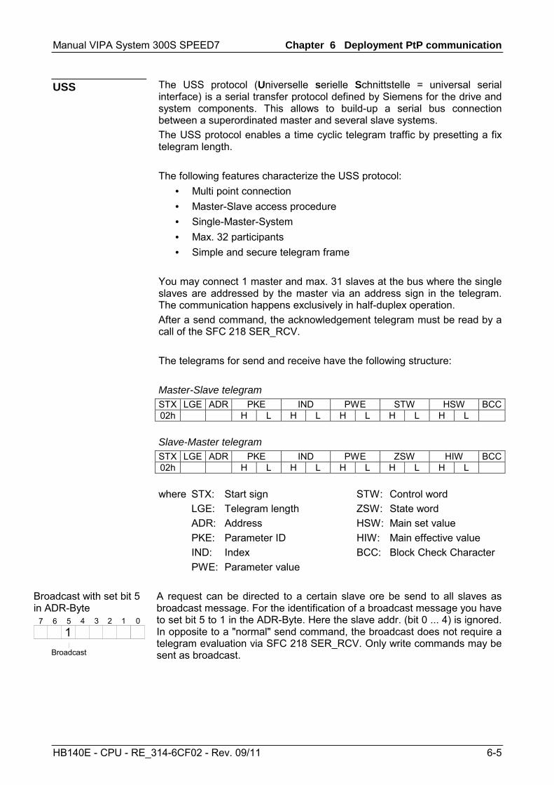
Manual VIPA System 300S SPEED7 Chapter 6 Deployment PtP communication
HB140E - CPU - RE_314-6CF02 - Rev. 09/11 6-5
The USS protocol (Universelle serielle Schnittstelle = universal serial interface) is a serial transfer protocol defined by Siemens for the drive and system components. This allows to build-up a serial bus connection between a superordinated master and several slave systems. The USS protocol enables a time cyclic telegram traffic by presetting a fix telegram length. The following features characterize the USS protocol:
• Multi point connection • Master-Slave access procedure • Single-Master-System • Max. 32 participants • Simple and secure telegram frame
You may connect 1 master and max. 31 slaves at the bus where the single slaves are addressed by the master via an address sign in the telegram. The communication happens exclusively in half-duplex operation. After a send command, the acknowledgement telegram must be read by a call of the SFC 218 SER_RCV. The telegrams for send and receive have the following structure: Master-Slave telegram STX LGE ADR PKE IND PWE STW HSW BCC02h H L H L H L H L H L Slave-Master telegram STX LGE ADR PKE IND PWE ZSW HIW BCC02h H L H L H L H L H L where STX: Start sign STW: Control word LGE: Telegram length ZSW: State word ADR: Address HSW: Main set value PKE: Parameter ID HIW: Main effective value IND: Index BCC: Block Check Character PWE: Parameter value
Broadcast with set bit 5 in ADR-Byte
01234567
Broadcast
1
A request can be directed to a certain slave ore be send to all slaves as broadcast message. For the identification of a broadcast message you have to set bit 5 to 1 in the ADR-Byte. Here the slave addr. (bit 0 ... 4) is ignored. In opposite to a "normal" send command, the broadcast does not require a telegram evaluation via SFC 218 SER_RCV. Only write commands may be sent as broadcast.
USS

Chapter 6 Deployment PtP communication Manual VIPA System 300S SPEED7
6-6 HB140E - CPU - RE_314-6CF02 - Rev. 09/11
The Modbus protocol is a communication protocol that fixes a hierarchic structure with one master and several slaves. Physically, Modbus works with a serial half-duplex connection. There are no bus conflicts occurring, because the master can only communicate with one slave at a time. After a request from the master, this waits for a preset delay time for an answer of the slave. During the delay time, communication with other slaves is not possible. After a send command, the acknowledgement telegram must be read by a call of the SFC 218 SER_RCV. The request telegrams send by the master and the respond telegrams of a slave have the following structure: Start sign
Slave address
Function Code
Data Flow control
End sign
A request can be directed to a special slave or at all slaves as broadcast message. To mark a broadcast message, the slave address 0 is used. In opposite to a "normal" send command, the broadcast does not require a telegram evaluation via SFC 218 SER_RCV. Only write commands may be sent as broadcast. Modbus offers 2 different transfer modes: • ASCII mode: Every byte is transferred in the 2 sign ASCII code. The
data are marked with a start and an end sign. This causes a transparent but slow transfer.
• RTU mode: Every byte is transferred as one character. This enables a higher data pass through as the ASCII mode. Instead of start and end sign, a time control is used.
The mode selection happens during runtime by using the SFC 216 SER_CFG. The following Modbus Protocols are supported by the RS485 interface • Modbus RTU Master • Modbus ASCII Master
Modbus
Broadcast with slave address = 0
ASCII, RTU mode
Supported Modbus protocols

Manual VIPA System 300S SPEED7 Chapter 6 Deployment PtP communication
HB140E - CPU - RE_314-6CF02 - Rev. 09/11 6-7
Deployment of RS485 interface for PtP
Per default, the RS485 interface X3 of the CPU is used for the Profibus DP master. Via hardware configuration the RS485 interfaces may be switched to point-to-point communication via the Parameter Function RS485 X3 of the Properties. The hardware configuration happens as described at "Project engineering" by means of a virtual Profibus system with the following approach:
Standard bus
virtual DP master for CPUand every SPEEDbus module
real Modulesat the standard bus
CPs resp. DP masterat SPEED-Bus as 343-1EX11 resp. 342-5DA02
(100) VIPA
VIPA_SPEEDBUSOrder no.CPU at slot 100
Slot0
(n) VIPA
VIPA_SPEEDBUSOrder no.Module at slot n
Slot0
...
Module
CPU 318-2DPMPI/DP
342-5DA02 V5.0
Slot12
X2X13
343-1EX11(Ethernet PG/OP)
• Start the Siemens hardware configurator and install the VIPA GSD file SPEEDBUS.GSD.
• Configure the Siemens CPU 318-2AJ00 (6ES7 318-2AJ00-0AB0/V3.0).
• Place the System 300 modules in the plugged sequence starting with slot 4.
• Configure a Siemens CP 343-1 (343-1EX11) for the internal Ethernet PG/OP channel below the really plugged System 300 modules.
• Start here to configure and link every Ethernet CP 343 - SPEED-Bus as Siemens CP 343-1 (343-1EX11) respec-tively every SPEED-Bus Profibus DP master as Siemens CP 342-5DA02 V5.0.
• Since the SPEED-Bus modules are to be linked as a virtual Profibus system, for the SPEED-Bus always as last module the Siemens DP master 342-5 (342-5DA02 V5.0) is to be configured. Link the DP master and switch it to DP master operating mode.
• Connect the slave system "VIPA_SPEEDbus". After installing the SPEEDBUS.GSD this may be found in the hardware catalog at Profibus-DP / Additional field devices / I/O / VIPA / VIPA_SPEEDBUS.
• For the slave system set the Profibus address 100. • Configure at slot 0 the VIPA CPU 314-6CF02 of the
hardware catalog from VIPA_SPEEDbus. • By double clicking the placed CPU 314-6CF02 the
properties dialog of the CPU may be opened. • Switch the Parameter Function RS485 X3 to "PtP". • To this master system you assign every further SPEED-
Bus module as "VIPA_SPEEDBUS" slave starting with the CPU. Here the Profibus address corresponds to the slot no. Beginning with 101. Place at slot 0 of every slave the assigned module and alter its parameters if needed.
After transferring your project to the CPU together with your PLC application, the RS485 interface is after the boot sequence available for PtP communication.
Switch to PtP operation
Hardware configuration

Chapter 6 Deployment PtP communication Manual VIPA System 300S SPEED7
6-8 HB140E - CPU - RE_314-6CF02 - Rev. 09/11
• Logical states represented by voltage differences between the two cores of a twisted pair cable
• Serial bus connection in two-wire technology using half duplex mode • Data communications up to a max. distance of 500m • Data communication rate up to 115.2kbaud
Pin Assignment 1 n.c. 2 M24V 3 RxD/TxD-P (Line B) 4 RTS 5 M5V 6 P5V 7 P24V 8 RxD/TxD-N (Line A)
5
4
3
2
1
9
8
7
6
9 n.c.
Connection
RxD/TxD-P (B)
RxD/TxD-N (A)
shield
CPU - RS485 Periphery
3
8
Periphery
Periphery
RxD/TxD-P (B)
RxD/TxD-N (A)
RxD/TxD-P (B)
RxD/TxD-N (A)
RxD/TxD-P (B)
RxD/TxD-N (A)
Properties RS485
Connection RS485

Manual VIPA System 300S SPEED7 Chapter 6 Deployment PtP communication
HB140E - CPU - RE_314-6CF02 - Rev. 09/11 6-9
Principle of the data transfer
The data transfer is handled during runtime by using SFCs. The principle of data transfer is the same for all protocols and is shortly illustrated in the following.
Data that is into the according data channel by the PLC, is stored in a FIFO send buffer (first in first out) with a size of 2x1024byte and then put out via the interface. When the interface receives data, this is stored in a FIFO receive buffer with a size of 2x1024byte and can there be read by the PLC. If the data is transferred via a protocol, the adoption of the data to the according protocol happens automatically. In opposite to ASCII and STX/ETX, the protocols 3964R, USS and Modbus require the acknowledgement of the partner. An additional call of the SFC 217 SER_SND causes a return value in RetVal that includes among others recent information about the acknowledgement of the partner. Further on for USS and Modbus after a SER_SND the acknowledgement telegram must be evaluated by call of the SFC 218 SER_RCV.
Protocol FIFO Buffer
1024Byte
1024Byte
1024Byte
1024Byte
IN
OUT
RS485
InterfaceProgram
SER_RCVSFC 218
CFG
RECEIVE
SENDSER_SNDSFC 217
SER_CFGSFC 216
RS485 PtP communication
Overview
Principle

Chapter 6 Deployment PtP communication Manual VIPA System 300S SPEED7
6-10 HB140E - CPU - RE_314-6CF02 - Rev. 09/11
Parameterization
The parameterization happens during runtime deploying the SFC 216 (SER_CFG). You have to store the parameters for STX/ETX, 3964R, USS and Modbus in a DB.
Name Declaration Type Comment Protocol IN BYTE 1=ASCII, 2=STX/ETX, 3=3964R Parameter IN ANY Pointer to protocol-parameters Baudrate IN BYTE Velocity of data transfer CharLen IN BYTE 0=5bit, 1=6bit, 2=7bit, 3=8bit Parity IN BYTE 0=None, 1=Odd, 2=Even StopBits IN BYTE 1=1bit, 2=1.5bit, 3=2bit FlowControl IN BYTE 1 (fix) RetVal OUT WORD Error Code ( 0 = OK )
All time settings for timeouts must be set as hexadecimal value. Find the Hex value by multiply the wanted time in seconds with the baudrate. Example: Wanted time 8ms at a baudrate of 19200baud Calculation: 19200bit/s x 0,008s ≈ 154bit → (9Ah) Hex value is 9Ah.
Here you fix the protocol to be used. You may choose between: 1: ASCII 2: STX/ETX 3: 3964R 4: USS Master 5: Modbus RTU Master 6: Modbus ASCII Master
SFC 216 (SER_CFG)
Parameter description
Protocol

Manual VIPA System 300S SPEED7 Chapter 6 Deployment PtP communication
HB140E - CPU - RE_314-6CF02 - Rev. 09/11 6-11
At ASCII protocol, this parameter is ignored. At STX/ETX, 3964R, USS and Modbus you fix here a DB that contains the communication parameters and has the following structure for the according protocols: Data block at STX/ETX DBB0: STX1 BYTE (1. Start-ID in hexadecimal) DBB1: STX2 BYTE (2. Start-ID in hexadecimal) DBB2: ETX1 BYTE (1. End-ID in hexadecimal) DBB3: ETX2 BYTE (2. End-ID in hexadecimal) DBW4: TIMEOUT WORD (max. delay time between 2 telegrams)
Note! The start res. end sign should always be a value <20, otherwise the sign is ignored! Data block at 3964R DBB0: Prio BYTE (The priority of both partners must be different) DBB1: ConnAttmptNr BYTE (Number of connection trials) DBB2: SendAttmptNr BYTE (Number of telegram retries) DBW4: CharTimeout WORD (Character delay time) DBW6: ConfTimeout WORD (Acknowledgement delay time) Data block at USS DBW0: Timeout WORD (Delay time in) Data block at Modbus-Master DBW0: Timeout WORD (Respond delay time)
Velocity of data transfer in bit/s (baud). 04h: 1200baud 05h: 1800baud 06h: 2400baud 07h: 4800baud 08h: 7200baud 09h: 9600baud 0Ah: 14400baud 0Bh: 19200baud0Ch: 38400baud 0Dh: 57600baud 0Eh: 115200baud
Number of data bits where a character is mapped to. 0: 5bit 1: 6bit 2: 7bit 3: 8bit
Parameter (as DB)
Baud rate
CharLen

Chapter 6 Deployment PtP communication Manual VIPA System 300S SPEED7
6-12 HB140E - CPU - RE_314-6CF02 - Rev. 09/11
The parity is -depending on the value- even or odd. For parity control, the information bits are extended with the parity bit that amends via its value ("0" or "1") the value of all bits to a defined status. If no parity is set, the parity bit is set to "1", but not evaluated. 0: NONE 1: ODD 2: EVEN
The stop bits are set at the end of each transferred character and mark the end of a character. 1: 1bit 2: 1.5bit 3: 2bit
The parameter FlowControl is ignored. When sending RTS=0, when receiving RTS=1.
Return values sent by the block:
Error code Description 0000h no error 809Ah interface not found 8x24h Error at SFC-Parameter x, with x:
1: Error at "Protocol" 2: Error at "Parameter" 3: Error at "Baudrate" 4: Error at "CharLength" 5: Error at "Parity" 6: Error at "StopBits" 7: Error at "FlowControl"
809xh Error in SFC parameter value x, where x: 1: Error at "Protocol" 3: Error at "Baudrate" 4: Error at "CharLength" 5: Error at "Parity" 6: Error at "StopBits" 7: Error at "FlowControl"
8092h Access error in parameter DB (DB too short) 828xh Error in parameter x of DB parameter, where x:
1: Error 1. parameter 2: Error 2. parameter ...
Parity
StopBits
FlowControl
RetVal SFC 216 (Error message SER_CFG)

Manual VIPA System 300S SPEED7 Chapter 6 Deployment PtP communication
HB140E - CPU - RE_314-6CF02 - Rev. 09/11 6-13
Communication
The communication happens via the send and receive blocks SFC 217 (SER_SND) and SFC 218 (SER_RCV). The SFCs are included in the consignment of the CPU.
This block sends data via the serial interface. The repeated call of the SFC 217 SER_SND delivers a return value for 3964R, USS and Modbus via RetVal that contains, among other things, recent information about the acknowledgement of the partner station. The protocols USS and Modbus require to evaluate the receipt telegram by calling the SFC 218 SER_RCV after SER_SND.
Name Declaration Type Comment DataPtr IN ANY Pointer to Data Buffer for sending data DataLen OUT WORD Length of data sent RetVal OUT WORD Error Code ( 0 = OK )
Here you define a range of the type Pointer for the send buffer where the data that has to be sent is stored. You have to set type, start and length. Example: Data is stored in DB5 starting at 0.0 with a length of 124byte. DataPtr:=P#DB5.DBX0.0 BYTE 124
Word where the number of the sent bytes is stored. At ASCII if data were sent by means of SFC 217 faster to the serial interface than the interface sends, the length of data to send could differ from the DataLen due to a buffer overflow. This should be considered by the user program. With STX/ETX, 3964R, Modbus and USS always the length set in DataPtr is stored or 0.
Overview
SFC 217 (SER_SND)
Parameter
DataPtr
DataLen

Chapter 6 Deployment PtP communication Manual VIPA System 300S SPEED7
6-14 HB140E - CPU - RE_314-6CF02 - Rev. 09/11
Return values of the block:
Error code Description 0000h Send data - ready 1000h Nothing sent (data length 0) 20xxh Protocol executed error free with xx bit pattern for diagnosis7001h Data is stored in internal buffer - active (busy) 7002h Transfer - active 80xxh Protocol executed with errors with xx bit pattern for
diagnosis (no acknowledgement by partner) 90xxh Protocol not executed with xx bit pattern for diagnosis (no
acknowledgement by partner) 8x24h Error in SFC parameter x, where x:
1: Error in "DataPtr" 2: Error in "DataLen"
8122h Error in parameter "DataPtr" (e.g. DB too short) 807Fh Internal error 809Ah Interface not found or interface is used for Profibus 809Bh Interface not configured
ASCII
Value Description 9000h Buffer overflow (no data send) 9002h Data too short (0byte)
STX/ETX
Value Description 9000h Buffer overflow (no data send) 9001h Data too long (>1024byte) 9002h Data too short (0byte) 9004h Character not allowed
3964R
Value Description 2000h Send ready without error 80FFh NAK received - error in communication 80FEh Data transfer without acknowledgement of partner or error
at acknowledgement 9000h Buffer overflow (no data send) 9001h Data too long (>1024byte) 9002h Data too short (0byte)
RetVal SFC 217 (Error message SER_SND)
Protocol specific RetVal values

Manual VIPA System 300S SPEED7 Chapter 6 Deployment PtP communication
HB140E - CPU - RE_314-6CF02 - Rev. 09/11 6-15
USS Error code Description
2000h Send ready without error 8080h Receive buffer overflow (no space for receipt) 8090h Acknowledgement delay time exceeded 80F0h Wrong checksum in respond 80FEh Wrong start sign in respond 80FFh Wrong slave address in respond 9000h Buffer overflow (no data send) 9001h Data too long (>1024byte) 9002h Data too short (<2byte)
Modbus RTU/ASCII Master
Error code Description 2000h Send ready without error 2001h Send ready with error 8080h Receive buffer overflow (no space for receipt) 8090h Acknowledgement delay time exceeded 80F0h Wrong checksum in respond 80FDh Length of respond too long 80FEh Wrong function code in respond 80FFh Wrong slave address in respond 9000h Buffer overflow (no data send) 9001h Data too long (>1024byte) 9002h Data too short (<2byte)
... Continue RetVal SFC 217 SER_SND

Chapter 6 Deployment PtP communication Manual VIPA System 300S SPEED7
6-16 HB140E - CPU - RE_314-6CF02 - Rev. 09/11
The following text shortly illustrates the structure of programming a send command for the different protocols.
3964R USS / Modbus
SFC 217SER_SND
Busy ?
RetVal 8xxxh / 90xxh ?
RetVal 2001h ?
RetVal 2000h ?
N
N
N
Error evaluation
End
J
J
J
Data evaluation
End
N
J
SFC 217SER_SND
Busy ?
RetVal 8xxxh / 90xxh ?
RetVal 2001h ?
RetVal 2000h ?
N
N
N
SFC 218SER_RCV
Error evaluation
End
J
J
J
SFC 218 SER_RCV
Data evaluation
End
N
J
ASCII / STX/ETX
SFC 217SER_SND
RetVal 900xh
Error evaluation
End
J
N
Principles of programming

Manual VIPA System 300S SPEED7 Chapter 6 Deployment PtP communication
HB140E - CPU - RE_314-6CF02 - Rev. 09/11 6-17
This block receives data via the serial interface. Using the SFC 218 SER_RCV after SER_SND with the protocols USS and Modbus the acknowledgement telegram can be read.
Name Declaration Type Comment DataPtr IN ANY Pointer to Data Buffer for received data DataLen OUT WORD Length of received data Error OUT WORD Error Number RetVal OUT WORD Error Code ( 0 = OK )
Here you set a range of the type Pointer for the receive buffer where the reception data is stored. You have to set type, start and length. Example: Data is stored in DB5 starting at 0.0 with a length of 124byte. DataPtr:=P#DB5.DBX0.0 BYTE 124 Word where the number of received Bytes is stored. At STX/ETX and 3964R, the length of the received user data or 0 is entered. At ASCII, the number of read characters is entered. This value may be different from the read telegram length. This word gets an entry in case of an error. The following error messages may be created depending on the protocol: ASCII Bit Error Description 0 overrun Overflow, a sign couldn’t be read fast enough from the
interface 1 framing error Error that shows that a defined bit frame is not
coincident, exceeds the allowed length or contains an additional Bit sequence (Stopbit error)
2 parity Parity error 3 overflow Buffer is full
STX/ETX Bit Error Description 0 overflow The received telegram exceeds the size of the receive
buffer. 1 char A sign outside the range 20h...7Fh has been received.3 overflow Buffer is full
3964R / Modbus RTU/ASCII Master
SFC 218 (SER_RCV)
Parameter
DataPtr
DataLen
Error
Bit Error Description 0 overflow The received telegram exceeds the size of the receive
buffer.

Chapter 6 Deployment PtP communication Manual VIPA System 300S SPEED7
6-18 HB140E - CPU - RE_314-6CF02 - Rev. 09/11
Return values of the block:
Error code Description 0000h no error 1000h Receive buffer too small (data loss) 8x24h Error at SFC-Parameter x, with x:
1: Error at "DataPtr" 2: Error at "DataLen" 3: Error at "Error"
8122h Error in parameter "DataPtr" (e.g. DB too short) 809Ah Serial interface not found res. interface is used by Profibus 809Bh Serial interface not configured
The following picture shows the basic structure for programming a receive command. This structure can be used for all protocols.
SFC 218SER_RCV
RetVal 0000h ?
RetVal 8xxxh ?
N Data evaluation
End
J
Error evaluation
End
N
J
RetVal SFC 218 (Error message SER_RCV)
Principles of programming

Manual VIPA System 300S SPEED7 Chapter 7 Deployment Profibus communication
HB140E - CPU - RE_314-6CF02 - Rev. 09/11 7-1
Chapter 7 Deployment Profibus communication
Content of this chapter is the deployment of the CPU 314ST/DPM with Profibus. After a short overview the project engineering and parameterization of a CPU 314ST/DPM with integrated Profibus-Part from VIPA is shown. Further you get information about usage as DP master and DP slave of the Profibus part. The chapter is ended with notes to commissioning and start-up.
Topic Page Chapter 7 Deployment Profibus communication........................... 7-1
Overview .............................................................................................. 7-2 Project engineering CPU with integrated Profibus master .................... 7-3 Deployment as Profibus DP slave ........................................................ 7-5 Profibus installation guidelines ............................................................. 7-7 Commissioning and Start-up behavior................................................ 7-10
Overview
Content
Chapter 7 Deployment Profibus communication Manual VIPA System 300S SPEED7
7-2 HB140E - CPU - RE_314-6CF02 - Rev. 09/11
Overview
Profibus is an international standard applicable to an open and serial field bus for building, manufacturing and process automation that can be used to create a low (sensor-/actuator level) or medium (process level) performance network of programmable logic controllers. Profibus comprises an assortment of compatible versions. The following details refer to Profibus-DP. Profibus-DP is a special protocol intended mainly for automation tasks in a manufacturing environment. DP is very fast, offers Plug'n'Play facilities and provides a cost-effective alternative to parallel cabling between PLC and remote I/O. Profibus-DP was designed for high-speed data communication on the sensor-actuator level. The data transfer referred to as "Data Exchange" is cyclical. During one bus cycle, the master reads input values from the slaves and writes output information to the slave.
The Profibus DP master is to configure via the hardware configurator from Siemens. Therefore you have to choose the Siemens-CPU 318-2AJ00 in the hardware configurator from Siemens. The transmission of your project engineering into the CPU takes place by means of MPI, MMC or Ethernet PG/OP channel. This is internally passing on your project data to the Profibus master part. During the start-up the DP master automatically includes his data areas into the address range of the CPU. Project engineering in the CPU is not required. As external storage medium the Profibus DP master uses the MMC (Multi Media Card) together with the CPU.
Via the Profibus DP master up to 125 Profibus DP slaves may be coupled to the CPU. The DP master communicates with the DP slaves and links up its data areas with the address area of the CPU. There may be created maximal 1024byte Input and 1024byte Output data. At every POWER ON res. overall reset the CPU fetches the I/O mapping data from the master. At DP slave failure, the ER-LED is on and the OB 86 is requested. If this is not available, the CPU switches to STOP and BASP is set. As soon as the BASP signal comes from the CPU, the DP master is setting the outputs of the connected periphery to zero. The DP master remains in the operating mode RUN independent from the CPU.
Please regard that the Profibus address 1 is reserved for the system. The address 1 should not be used! For the deployment in a super-ordinated master system you first have to project your slave system as CPU 318-2 (6ES7 318-2AJ00-0AB0/V3.0) in Slave operation with configured in-/output areas. Afterwards you configure your master system. Assign your slave system to your master system by dragging the SPEED7-CPU from the hardware catalog at Configured stations onto the master system, choose your slave system and connect it.
Profibus-DP
CPU with DP master
Deployment of the DP-Master with CPU
Profibus address 1 is reserved
DP slave operation

Manual VIPA System 300S SPEED7 Chapter 7 Deployment Profibus communication
HB140E - CPU - RE_314-6CF02 - Rev. 09/11 7-3
Project engineering CPU with integrated Profibus master
For the project engineering of the Profibus DP master you have to use the hardware manager from Siemens. Your Profibus projects are transferred via MPI to the CPU by means of the "PLC" functions. The CPU passes the data on to the Profibus DP master.
For the project engineering of the Profibus DP master in the CPU 314ST/DPM the following preconditions have to be fulfilled: • Siemens SIMATIC Manager has to be installed. • With Profibus DP slaves of the Systems 100V, 200V and 300 from
VIPA: GSD Files are included into the hardware configurator. • There is a transfer possibility between configuration tool and CPU.
Note! For the project engineering of the CPU and the Profibus DP master a thorough knowledge of the Siemens SIMATIC manager is required!
The hardware configurator is a part of the Siemens SIMATIC Manager. It serves the project engineering. The modules that may be configured here, are listed in the hardware catalog. For the deployment of the Profibus DP slaves of the Systems 100V, 200V and 300V from VIPA you have to include the modules into the hardware catalog by means of the GSD file from VIPA.
• Create a new project System 300. • Add a profile rail from the hardware catalog. • In the hardware catalog the CPU with Profibus master is listed as:
Simatic300/CPU-300/CPU318-2/6ES7 318-2AJ00-0AB0
• Insert the CPU 318-2 (6ES7 318-2AJ00-0AB0). • Type the Profibus address of your master (e.g.: 2). • Click on DP, choose the operating mode "DP master" under object
properties and confirm your entry with OK. • Click on "DP" with the right mouse button and choose "add master
system". • Create a new Profibus subnet via NEW.
Overview
Preconditions
Install Siemens Hardware configurator
Configure DP master

Chapter 7 Deployment Profibus communication Manual VIPA System 300S SPEED7
7-4 HB140E - CPU - RE_314-6CF02 - Rev. 09/11
Now the project engineering of your Profibus DP master is finished. Please link up now your DP slaves with periphery to your DP master. • For the project engineering of Profibus DP slaves you search the
concerning Profibus-DP slave in the hardware catalog and drag&drop it in the subnet of your master.
• Assign a valid Profibus address to the DP slave. • Link up the modules of your DP slave system in the plugged sequence
and add the addresses that should be used by the modules. • If needed, parameterize the modules. • Save, compile and transfer your project. More detailed information about
SPEED-Bus project engineering and project transfer may be found at chapter "Deployment CPU 314ST/DPM".
Note! If you deploy an IM153 from Siemens under a VIPA CPU 314ST/DPM, please use the "compatible" DP slave modules. These are listed in the hardware catalog under PROFIBUS-DP/Additional Field Devices/ Compatible Profibus-DP-Slaves.
You may deploy your Profibus part from your SPEED7-CPU as DP slave. The approach is described on the following page.
Slave operation possible

Manual VIPA System 300S SPEED7 Chapter 7 Deployment Profibus communication
HB140E - CPU - RE_314-6CF02 - Rev. 09/11 7-5
Deployment as Profibus DP slave
The deployment of the Profibus section as "intelligent" DP slave happens exclusively at master systems that may be configured in the Siemens SIMATIC manager. The following steps are required: • Start the Siemens SIMATIC manager and configure a CPU 318-2 with
the operating mode DP slave. • Connect to Profibus and configure the in-/output area for the slave
section. • Save and compile your project. • Configure another station as CPU 318-2 with operating mode DP
master. • Connect to Profibus and configure the in-/output ranges for the master
section • Save and compile your project. In the following these steps are more detailed.
• Start the Siemens SIMATIC manager with a new project. • Insert a SIMATIC 300 station and name it as "...DP slave" • Open the hardware configurator and insert a profile rail from the
hardware catalog. • Place the following Siemens CPU at slot 2:
CPU 318-2 (6ES7 318-2AJ00-0AB0 V3.0) • Add your modules according to the real hardware assembly. • Connect the CPU to Profibus, set a Profibus address >1 (preferably 3)
and switch the Profibus section via operating mode to "slave operation". • Via Configuration you define the in-/output address area of the slave
CPU that shall be assigned to the DP slave. • Save and compile your project.
Module
CPU 318-2DPMPI/DP
I/O devices...
Standard busSlot
12
X2X1
3
Object propertiesOperating mode: DP slaveConnect: ProfibusProfibus address: > 1
Configuration:Input area Output area
Slave section
Fast introduction
Project engineering of the slave section

Chapter 7 Deployment Profibus communication Manual VIPA System 300S SPEED7
7-6 HB140E - CPU - RE_314-6CF02 - Rev. 09/11
• Insert another SIMATIC 300 station and name it as "...DP master". • Open the hardware configurator and insert a profile rail from the
hardware catalog. • Place the following Siemens CPU at slot 2:
CPU 318-2 (6ES7 318-2AJ00-0AB0 V3.0) • Add your modules according to the real hardware assembly. • Connect the CPU to Profibus, set a Profibus address >1 (preferably 2)
and switch the Profibus section via operating mode to "master operation".
• Connect your slave system to the master system by dragging the CPU 31xS from the hardware catalog at configured stations onto the master system and select your slave system.
• Open the Configuration at Object properties of your slave system. • Via double click to the according configuration line you assign the
according input address area on the master CPU to the slave output data and the output address area to the slave input data.
• Save, compile and transfer your project. More detailed information about SPEED-Bus project engineering and project transfer may be found at chapter "Deployment CPU 314ST/DPM".
Module
CPU 318-2DPMPI/DP
I/O devices...
Standard busSlot
12
X2X13
Object propertiesOperating mode: DP masterConnect: ProfibusProfibus address: > 1
Master section
DP master system
S7-300Hardware catalog: CPU 31x from configured stations
Object propertiesConfiguration:Input area slave CPU = Output area master-CPUOutput area slave CPU = Input area Master-CPU
12
3
Project engineering of the master section

Manual VIPA System 300S SPEED7 Chapter 7 Deployment Profibus communication
HB140E - CPU - RE_314-6CF02 - Rev. 09/11 7-7
Profibus installation guidelines
• A Profibus-DP network may only be built up in linear structure. • Profibus-DP consists of minimum one segment with at least one master
and one slave. • A master has always been deployed together with a CPU. • Profibus supports max. 126 participants. • Per segment a max. of 32 participants is permitted. • The max. segment length depends on the baud rate:
9.6 ... 187.5kbaud → 1000m 500kbaud → 400m 1.5Mbaud → 200m 3 ... 12Mbaud → 100m
• Max. 10 segments may be built up. The segments are connected via repeaters. Every repeater counts for one participant.
• All participants are communicating with the same baudrate. The slaves adjust themselves automatically on the baudrate.
• The bus has to be terminated at both ends. • Master and slaves are free combinable.
As transfer medium Profibus uses an isolated twisted-pair cable based upon the RS485 interface. The RS485 interface is working with voltage differences. Though it is less irritable from influences than a voltage or a current interface. You are able to configure the network as well linear as in a tree structure. Your VIPA CPU includes a 9pin slot where you connect the Profibus coupler into the Profibus network as a slave. Max. 32 participants per segment are permitted. The segments are connected via repeaters. The maximum segment length depends on the transfer rate. Profibus-DP uses a transfer rate between 9.6kbaud and 12Mbaud, the slaves are following automatically. All participants are communicating with the same baudrate. The bus structure under RS485 allows an easy connection res. disconnection of stations as well as starting the system step by step. Later expansions don’t have any influence on stations that are already integrated. The system realizes automatically if one partner had a fail down or is new in the network.
Profibus in general
Transfer medium

Chapter 7 Deployment Profibus communication Manual VIPA System 300S SPEED7
7-8 HB140E - CPU - RE_314-6CF02 - Rev. 09/11
The following picture illustrates the terminating resistors of the respective start and end station.
RxD/TxD-P(B)
Shield
Master Slave
3
8
3
8
P5V P5V
M5V M5V
330 330
330 330
220 220
3
8RxD/TxD-N(A)
5
6
RxD/TxD-P(B)
RxD/TxD-N(A)
Slave
RxD/TxD-P(B)
RxD/TxD-N(A)
5
3
8
6
Shield Shield
Note! The Profibus line has to be terminated with its ripple resistor. Please make sure to terminate the last participants on the bus at both ends by activating the terminating resistor.
In systems with more than two stations all partners are wired in parallel. For that purpose, the bus cable must be feed-through uninterrupted. Via the order number VIPA 972-0DP10 you may order the bus connector "EasyConn". This is a bus connector with switchable terminating resistor and integrated bus diagnostic.
C
A
B
90°
A
B
0°
B
A
45°
0° 45° 90° A 64 61 66 B 34 53 40 C 15.8 15.8 15.8
all in mm
Bus connection
EasyConn bus connector

Manual VIPA System 300S SPEED7 Chapter 7 Deployment Profibus communication
HB140E - CPU - RE_314-6CF02 - Rev. 09/11 7-9
Note! To connect this EasyConn plug, please use the standard Profibus cable type A (EN50170). Starting with release 5 you also can use highly flexible bus cable: Lapp Kabel order no.: 2170222, 2170822, 2170322. With the order no. 905-6AA00 VIPA offers the "EasyStrip" de-isolating tool that makes the connection of the EasyConn much easier.
11 6
Dimensions in mm The "EasyConn" bus connector is provided with a switch that is used to activate a terminating resistor.
Attention! The terminating resistor is only effective, if the connector is installed at a slave and the slave is connected to a power supply. Note! A complete description of installation and deployment of the terminating resistors is delivered with the connector.
• Loosen the screw. • Lift contact-cover. • Insert both wires into the ducts
provided (watch for the correct line color as below!)
• Please take care not to cause a short circuit between screen and data lines!
• Close the contact cover. • Tighten screw
(max. tightening torque 4Nm). The green line must be connected to A, the red line to B!
Termination with "EasyConn"
Assembly
Please note:

Chapter 7 Deployment Profibus communication Manual VIPA System 300S SPEED7
7-10 HB140E - CPU - RE_314-6CF02 - Rev. 09/11
Commissioning and Start-up behavior
In delivery the CPU is overall reset. The Profibus part is deactivated and its LEDs are off after Power ON.
The DP master can be served with bus parameters by means of a hardware configuration. As soon as these are transferred the DP master goes online with his bus parameter. This is shown by the RUN LED. Now the DP master can be contacted via Profibus by means of his Profibus address. In this state the CPU can be accessed via Profibus to get configuration and DP slave project.
If the master has received valid configuration data, he switches to Data Exchange with the DP Slaves. This is indicated by the DE-LED.
After PowerON respectively a receipt of a new hardware configuration the configuration data and bus parameter were transferred to the DP master. The DP master does not have any operation switch. His state is controlled by the RUN/STOP state of the CPU. Dependent on the CPU state the following behavior is shown by the DP master: • The global control command "Operate" is sent to the slaves by the
master. Here the DE-LED is ON. • Every connected DP slave is cyclically attended with an output telegram
containing recent output data. • The input data of the DP slaves were cyclically transferred to the input
area of the CPU. • The global control command "Clear" is sent to the slaves by the master.
Here the DE-LED is blinking. • DP slaves with fail safe mode were provided with output telegram length
"0". • DP slaves without fail safe mode were provided with the whole output
telegram but with output data = 0. • The input data of the DP slaves were further cyclically transferred to the
input area of the CPU.
Start-up on delivery
Online with bus parameter without slave project
Slave configuration
CPU state controls DP master
Master behavior at CPU RUN
Master behavior at CPU STOP

Manual VIPA System 300S SPEED7 Chapter 8 WinPLC7
HB140E - CPU - RE_314-6CF02 - Rev. 09/11 8-1
Chapter 8 WinPLC7
In this chapter the programming and simulation software WinPLC7 from VIPA is presented. WinPLC7 is suited for every with Siemens STEP®7 programmable PLC. Besides the system presentation and installation here the basics for using the software is explained with a sample project. More information concerning the usage of WinPLC7 may be found in the online help respectively in the online documentation of WinPLC7.
Topic Page Chapter 8 WinPLC7 .......................................................................... 8-1
System presentation............................................................................. 8-2 Installation............................................................................................ 8-3 Example project engineering ................................................................ 8-4
Overview
Content

Chapter 8 WinPLC7 Manual VIPA System 300S SPEED7
8-2 HB140E - CPU - RE_314-6CF02 - Rev. 09/11
System presentation
WinPLC7 is a programming and simulation software from VIPA for every PLC programmable with Siemens STEP®7. This tool allows you to create user applications in FBD, LAD and STL. Besides of a comfortable programming environment, WinPLC7 has an integrated simulator that enables the simulation of your user application at the PC without additional hardware. This “Soft-PLC” is handled like a real PLC and offers the same error behavior and diagnosis options via diagnosis buffer, USTACK and BSTACK. Note! Detailed information and programming samples may be found at the online help respectively in the online documentation of WinPLC7.
There is also the possibility to use the Siemens SIMATIC manager instead of WinPLC7 from VIPA. Here the proceeding is part of this manual.
• Pentium with 233MHz and 64Mbyte work space • Graphics card with at least 16bit color - we recommend a screen
resolution of at least 1024x768 pixel. • Windows 98SE/ME, Windows 2000,
Windows XP (Home and Professional), Windows Vista
You may receive a demo version from VIPA. Without any activation with the demo version the CPUs 11x of the System 100V from VIPA may be configured. To configure the SPEED7 CPUs a license for the "profi" version is necessary. This may be online received and activated. There are the following sources to get WinPLC7: At www.vipa.de in the service area at Downloads a link to the current demo version and the updates of WinPLC7 may be found. Order no. Description SW211C1DD WinPLC7 Single license, CD, with documentation in german SW211C1ED WinPLC7 Single license, CD, with documentation in english SW900T0LA ToolDemo
VIPA software library free of charge respectively demo versions, which may be activated
General
Alternatives
System requirements
Source
Online
CD

Manual VIPA System 300S SPEED7 Chapter 8 WinPLC7
HB140E - CPU - RE_314-6CF02 - Rev. 09/11 8-3
Installation
The project engineering of a SPEED7 CPU from VIPA with WinPLC7 is only possible using an activated "Profi" version of WinPLC7. The installation and the registration of WinPLC7 has the following approach: • For installation of WinPLC7 start the setup program of the
corresponding CD respectively execute the online received exe file. • Choose the according language. • Agree to the software license contract. • Set an installation directory and a group assignment and start the
installation. • Start WinPLC7. A "Demo" dialog is shown. • Press the <q> key. The following dialog for activation is shown:
• Fill in the following fields: Email-Addr., Your Name und Serial number. The serial number may be found on a label at the CD case.
• If your computer is connected to Internet you may online request the Activation Key by [Get activation key via Internet]. Otherwise click at [This PC has no access to the internet] and follow the instructions.
• With successful registration the activation key is listed in the dialog window respectively is sent by email.
• Enter the activation key and click to [OK]. Now, WinPLC7 is activated as "Profi" version.
To find a station via Ethernet (accessible nodes) you have to install the WinPCAP driver. This driver may be found on your PC in the installation directory at WinPLC7-V4/WinPcap_4_0.exe. Execute this file and follow the instructions.
Preconditions
Installation WinPLC7 Demo
Activation of the "Profi" version
Installation of WinPCAP for station search via Ethernet

Chapter 8 WinPLC7 Manual VIPA System 300S SPEED7
8-4 HB140E - CPU - RE_314-6CF02 - Rev. 09/11
Example project engineering
In the example a FC 1 is programmed, which is cyclically called by the OB 1. By setting of 2 comparison values (value1 and value2) during the FC call, an output of the PLC-System should be activated depending on the comparison result. if value1 = value2 activate output Q 124.0 if value1 > value2 activate output Q 124.1 if value1 < value2 activate output Q 124.2
• You have administrator rights for your PC. • WinPLC7 is installed and activated as "Profi" version. • One CPU and one digital output module are installed and cabled. • The Ethernet PG/OP channel of the CPU is connected to your Ethernet
network. Your CPU may be connected to your PC with an Ethernet cable either directly or via hub/switch.
• WinPCap for station search via Ethernet is installed. • The power supply of the CPU and the I/O periphery are activated and
the CPU is in STOP state.
• Start WinPLC7 ("Profi" version) • Create and open a new project by File > Open/create a project.
• For the call of the hardware configurator it is necessary to set WinPLC7 from the Simulator-Mode to the Offline-Mode. For this and the communi-cation via Ethernet set "Target: TCP/IP Direct".
• Start the hardware configurator with . Please regard an object is selected with a double click at an object in the hardware configurator.
• Choose in the register Select PLC-System the parameter "VIPA SPEED7" and click to [Create]. A new station is created.
• Save the empty station. A station name and a comment may be entered before saving.
• By double click choose the according VIPA CPU in the hardware catalog at CPU SPEED7.
• For output place a digital output module and assign the start address 124. • Save the hardware configuration.
Job definition
Here it should apply:
Precondition
Project engineering
Hardware configuration

Manual VIPA System 300S SPEED7 Chapter 8 WinPLC7
HB140E - CPU - RE_314-6CF02 - Rev. 09/11 8-5
• Open the CPU-Properties, by double clicking to the CPU at slot 2 in the hardware configurator.
• Click to the button [Ethernet CP-Properties (PG/OP-channel)]. The Properties CP343 is opened.
• Chose the register Common Options. • Click to [Properties Ethernet]. • Choose the subnet "PG_OP_Ethernet". • Enter a valid IP address-and a subnet mask. You may get this from your
system administrator. • Close every dialog window with [OK]. • Select, if not already done, "Target: External TCP/IP direct". • Open with Online > Send configuration to the CPU a dialog with the
same name. • Click to [Accessible nodes]. Please regard to use this function it is
necessary to install WinPCap before! • Choose your network card and click to [Determining accessible nodes].
After a waiting time every accessible station is listed. Here your CPU with IP 0.0.0.0 is listed, too. To check this the according MAC address is also listed. This MAC address may be found at a label beneath the front flap of the CPU.
• For the temporary setting of an IP address select you CPU and click to [Temporary setting of the IP parameters]. Please enter the same IP parameters, you configured in the CPU properties and click to [Write Parameters].
• Confirm the message concerning the overall reset of the CPU. The IP parameters are transferred to the CPU and the list of accessible stations is refreshed.
• Select you CPU and click to [Confirm]. Now you are back in the dialog "Send configuration".
• Choose your network card and click to [Send configuration]. After a
short time a message is displayed concerning the transfer of the configuration is finished.
Note! Usually the online transfer of the hardware configuration happens within the hardware configurator. With File > Save active station in the WinPL7 sub project there is also the possibility to store the hardware configuration as a system file in WinPLC7 to transfer it from WinPLC7 to the CPU.
The hardware configuration is finished, now and the CPU may always be accessed by the IP parameters as well by means of WinPLC7.
Online access via Ethernet PG/OP channel
Transfer hardware configuration

Chapter 8 WinPLC7 Manual VIPA System 300S SPEED7
8-6 HB140E - CPU - RE_314-6CF02 - Rev. 09/11
The PLC programming happens by WinPLC7. Close the hardware configurator and return to your project in WinPLC7. The PLC program is to be created in the FC 1. • Choose File > Create new block. • Enter "FC1" as block and confirm with [OK]. The editor for FC 1 is
called. In the upper part of the editor there is the parameter table. In this example the 2 integer values value1 und value2 are to be compared together. Since both values are read only by the function, these are to be defined as "in". • Select the "in -->" row at the parameter table and enter at the field
Name "value1". Press the [Return] key. The cursor jumps to the column with the data type.
• The data type may either directly be entered or be selected from a list of available data types by pressing the [Return] key. Set the data type to INT and press the [Return] key. Now the cursor jumps to the Comment column.
• Here enter "1. compare value" and press the [Return] key. A new "in -->" row is created and the cursor jumps to Name.
• Proceed for value2 in the same way as described for value1. • Save the block. The parameter table shows the following entries, now:
As requested in the job definition, the corresponding output is activated depending on the comparison of value1 and value2. For each comparison operation a separate network is to be created. • The program is to be created as FBD (function block diagram). Here
change to the FBD view by clicking at FBD.
• Click to the input field designated as "empty".
The available operations may be added to your project by drag&drop from the hardware catalog or by double click at them in the hardware catalog.
Programming of the FC 1
Creating block FC 1
Creating parameters
Enter the program

Manual VIPA System 300S SPEED7 Chapter 8 WinPLC7
HB140E - CPU - RE_314-6CF02 - Rev. 09/11 8-7
• Open in the catalog the category "Comparator" and add the operation "CMP==I" to your network.
• Click to the input left above and insert value1. Since these are block
parameters a selection list of block parameters may be viewed by entering "#".
• Type in "#" and press the [Return] key. • Choose the corresponding parameter and confirm it with the [Return]
key. • Proceed in the same way with the parameter value2. The allocation to the corresponding output, here Q 124.0, takes place with the following proceeding: • Click to the output at the right side of the operator.
• Open in the catalog the category "Bit logic" and select the function
"--[=]". The inserting of "--=" corresponds to the WinPLC7 shortcut [F7]. • Insert the output Q 124.0 by clicking to the operand.
Network1 is finished, now.

Chapter 8 WinPLC7 Manual VIPA System 300S SPEED7
8-8 HB140E - CPU - RE_314-6CF02 - Rev. 09/11
For further comparisons the operations "CMP>I" at Q 124.1 and "CMP<I" at Q 124.2 are necessary. Create a network for both operations with the following proceeding: • Move your mouse at an arbitrary position on the editor window and
press the right mouse key. • Select at the context menu "Insert new network". A dialog field is
opened to enter the position and number of the networks. • Proceed as described for "Network 1". • Save the FC 1 with File > Save content of focused window respectively
press [Strg]+[S]. After you have programmed the still missing networks, the FC 1 has the following structure:
Adding a new network

Manual VIPA System 300S SPEED7 Chapter 8 WinPLC7
HB140E - CPU - RE_314-6CF02 - Rev. 09/11 8-9
The FC 1 is to be called from the cycle OB 1. • To create the OB 1 either you select File > Create new block or click to
button [Display OB 1] and create the OB 1. • Change to the STL view. • Type in "Call FC 1" and press the [Return] key. The FC parameters are
automatically displayed and the following parameters are assigned:
• Save the OB 1 with File > Save content of focused window respectively
press [Strg]+[S].
With WinPLC7 there is the possibility to test your project in a simulator. • Here select "Target: Simulator".
• Transfer the blocks to the simulator with PLC > Send all blocks. • Switch the CPU to RUN, by clicking to the photo "Switch/Operating
mode" and select in the dialog window the button [Warm restart]. The displayed state changes from STOP to RUN.
• To view the process image select View > Display process image window.
• Double click to the process image and enter at "Line 2" the address PQB124. Confirm with [OK]. A value marked by red color corresponds to a logical "1".
• Open the OB 1 with the button [Display OB 1]. • Change the value of one variable, save the OB 1 and transfer it to the
simulator. According to your settings the process image changes immediately. The status of your blocks may be displayed with Block > Monitoring On/Off.
Creating the block OB 1
Test the PLC program in the Simulator

Chapter 8 WinPLC7 Manual VIPA System 300S SPEED7
8-10 HB140E - CPU - RE_314-6CF02 - Rev. 09/11
A further component of the simulator is the PLC mask. Here a CPU is graphically displayed, which may be expanded by digital and analog peripheral modules. As soon as the CPU of the simulator is switched to RUN state, inputs may be activated by mouse and outputs may be displayed. • Open the PLC mask with view > PLC mask. A CPU is graphically
displayed. • By clicking the right mouse button within the PLC mask the context
menu is opened. Choose for this example "Insert 16-port digital input module". The module is displayed at the right side of the CPU.
• Double-click to the output module, open its properties dialog and enter the Module address 124.
• Switch the operating mode switch to RUN by means of the mouse. Your program is executed and displayed in the simulator, now.
• For transfer to the CPU set the transfer mode to "Target: TCP/IP-Direct".
• For presetting the Ethernet data click to [...] and click to [Accessible nodes].
• Choose your network card and click to [Determining accessible nodes]. After a waiting time every accessible station is listed.
• Choose your CPU, which was provided with TCP/IP address parameters during the hardware configuration and click to [Confirm].
• Close the "Ethernet properties" dialog with [OK]. • Transfer the blocks to your CPU with PLC > Send all blocks. • Switch your CPU to RUN state. • Open the OB 1 with the button [Display OB 1]. • Change the value of one variable, save the OB 1 and transfer it to the
CPU. According to your settings the process image changes imme-diately. The status of your blocks may be displayed with Block > Monitoring On/Off.
Visualization via PLC mask
Transfer PLC program to CPU and its execution

Manual VIPA System 300S SPEED7 Index
HB140E - CPU - RE_314-6CF02 - Rev. 09/11 A-1
Appendix A Index
3 3964R ........................................... 6-4
A Access options.............................. 1-8 Address assignment ............4-10, 5-4 Addressing.................................... 4-7
automatically............................. 4-8 Example.................................... 4-9
Analog part ............................3-9, 5-5 Access ...................................... 5-6 Conversion................................ 5-8 deactivate ................................. 5-7 Diagnostic functions ............... 5-13 Diagnostic interrupt................. 5-10 Function No. ........................... 5-11 Measuring cycle...................... 5-10 Number representation............. 5-7 Parameters ............................... 5-9 Pin assignment ......................... 5-5 Resolution................................. 5-7 STOP reaction ........................ 5-10 Substitute value ...................... 5-10 Wire break recognition ........... 5-10
ASCII ............................................ 6-3 Assembly ...................................... 2-1
Alignment...........................2-4, 4-2 Approach ...........................2-4, 4-2 SPEED-Bus .......................2-5, 4-3 Standard bus......................2-4, 4-2
B Basics ........................................... 1-1 Battery buffer ................................ 4-6 Breakpoints................................. 4-39
C Cabling.......................................... 2-8
Front connectors....................... 2-9 Communication
PG/OP ...........................4-11, 4-37 RS485....................................... 3-6
Profibus................................ 3-6 PtP ....................................... 3-7
Compatibility ................................. 1-7 Core cross-section........................ 1-9
Cycle time surveillance............... 4-40
D Deployment
CPU.......................................... 4-1 I/O periphery............................. 5-1 Profibus .................................... 7-1 PtP communication .................. 6-1
Diagnostic.......................... 5-10, 5-23 Buffer...................................... 4-52 Counter................................... 5-39
Diagnostic interrupt..................... 5-40 Digital part ......................... 3-10, 5-16
Access.................................... 5-17 Counter................................... 5-18
Comparison ....................... 5-35 Comparison value.............. 5-25 Count abort ........................ 5-26 Count continuously ............ 5-27 Count interrupt ................... 5-26 Count once ........................ 5-28 Count periodically .............. 5-30 Edge selection ................... 5-24 End value........................... 5-25 Fast introduction ................ 5-18 Gate function ..................... 5-33 Hysteresis ................. 5-25, 5-36 Input filter ........................... 5-24 Latch function .................... 5-35 Load value ......................... 5-25 Main counting direction...... 5-26 Mode.................................. 5-22 Parameter .......................... 5-21 Process interrupt................ 5-39 Pulse.................................. 5-25 Value set once ................... 5-25
deactivate ............................... 5-25 Diagnostic interrupt ................ 5-23 Pin assignment....................... 5-16
E EMC............................................ 2-11
Basic rules.............................. 2-12 Environmental conditions ............. 1-9 ESD .............................................. 1-9 Ethernet PG/OP channel ... 4-11, 4-37 Event-ID...................................... 4-52

Index Manual VIPA System 300S SPEED7
A-2 HB140E - CPU - RE_314-6CF02 - Rev. 09/11
F Factory setting ...................4-42, 4-46 Fast introduction
Project engineering................. 4-16 PtP communication................... 6-2
Firmware Info by Web page ................... 4-44 transfer ................................... 4-45 Update .................................... 4-43
G GSD include................................ 4-17
H Hardware configuration............... 4-16 Hardware description.................... 3-1
I In-/Output range............................ 3-8 Initialization ................................. 4-11 Installation dimensions ................. 2-3 Installation guidelines...........2-1, 2-11 Interfaces ...................................... 3-4
Ethernet PG/OP........................ 3-4 MPI ........................................... 3-4 RS485....................................... 3-6
Profibus................................ 3-6 PtP ................................3-7, 6-1
Interference influences ............... 2-11 Isolation of conductors................ 2-13
K Know-how protection .................. 4-48
L LEDs ............................................. 3-5
M MCC............................................ 4-47 Memory extension ...................... 4-47 Memory management................... 3-5 MMC ........................................... 4-36
-Cmd - Auto commands ......... 4-50 Project transfer ....................... 4-36
Diagnostic .......................... 4-36 Modbus ......................................... 6-6
O Operating mode.......................... 4-38
Switch ....................................... 3-4 Overall reset ............................... 4-41
Factory setting ........................ 4-42
Overview CPU.......................................... 1-7 System 300 .............................. 1-3
P Parameterization
Modules.................................. 4-33 Standard CPU parameters ..... 4-22 VIPA spec. CPU parameters.. 4-29
PG/OP channel.................. 4-11, 4-37 pkg-files ...................................... 4-43 PLC functions ............................. 4-57 Power supply ......................... 1-9, 3-5 Procedures ................................... 6-4 Process image.............................. 4-7 Profibus
Baud rate.................................. 7-7 Connectors ............................... 7-8 De-isolating lengths.................. 7-9 Installation guidelines ............... 7-7 Line termination........................ 7-9 Transfer medium ...................... 7-7
Profibus DP master ...................... 7-1 Commissioning....................... 7-10 Deployment as DP slave .......... 7-5 Interface ................................... 3-7 Overview................................... 7-2 Start-up behavior.................... 7-10 Synchronization ...................... 4-30
Project engineering..................... 4-16 Bus extension........................... 4-7 Fast introduction..................... 4-16 Steps ...................................... 4-18 Transfer .................................. 4-34
Project transfer ........................... 4-34 Properties ..................................... 3-2 PtP communication ...................... 6-1
3964R....................................... 6-4 ASCII ........................................ 6-3 Broadcast ................................. 6-5 Communication ...................... 6-13 Error messages....6-12, 6-14, 6-17 Fast introduction....................... 6-2 Modbus..................................... 6-6 Parameterization .................... 6-10 Principle data transfer .............. 6-9 Protocols .................................. 6-3 RS485 interface........................ 6-7 SFCs ...................................... 6-13 STX/ETX .................................. 6-3 USS .......................................... 6-5
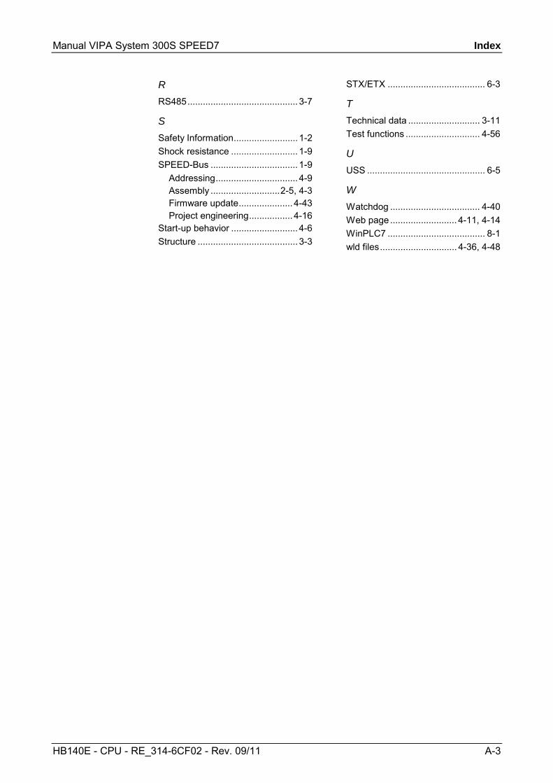
Manual VIPA System 300S SPEED7 Index
HB140E - CPU - RE_314-6CF02 - Rev. 09/11 A-3
R RS485........................................... 3-7
S Safety Information......................... 1-2 Shock resistance .......................... 1-9 SPEED-Bus .................................. 1-9
Addressing................................ 4-9 Assembly ...........................2-5, 4-3 Firmware update..................... 4-43 Project engineering................. 4-16
Start-up behavior .......................... 4-6 Structure ....................................... 3-3
STX/ETX ...................................... 6-3
T Technical data ............................ 3-11 Test functions ............................. 4-56
U USS .............................................. 6-5
W Watchdog ................................... 4-40 Web page .......................... 4-11, 4-14 WinPLC7 ...................................... 8-1 wld files.............................. 4-36, 4-48

Index Manual VIPA System 300S SPEED7
A-4 HB140E - CPU - RE_314-6CF02 - Rev. 09/11
M.Stich
![Extra 300S [40]](https://static.fdocuments.net/doc/165x107/577cd5791a28ab9e789ae1cf/extra-300s-40.jpg)


![Lenovo Ideacentre 300S Hmm 20151104 ideacentre 300S Series … · 2015. 11. 4. · ideacentre 300S Series Hardware Maintenance Manual Machine Types: 90DQ [300S-11IBR/Energy Star]](https://static.fdocuments.net/doc/165x107/60cfbab2aece5111e35d5c92/lenovo-ideacentre-300s-hmm-20151104-ideacentre-300s-series-2015-11-4-ideacentre.jpg)


