MANUAL HARD COPY DISTRIBUTION DOCUMENT TRANSMITTAL 2005-35786 · aug. 25, 2005 page 1 of 2 manual...
46
Aug. 25, 2005 Page 1 of 2 MANUAL HARD COPY DISTRIBUTION DOCUMENT TRANSMITTAL 2005-35786 USER INFORMATION: GERLACH*ROSE M EMPL#:028401 CA#: 0363 Address: NUCSA2 Phone#: 254-3194 TRANSMITTAL INFORMATION: TO: GERLACH*ROSE M 08/25/2005 LOCATION: USNRC FROM: NUCLEAR RECORDS DOCUMENT CONTROL CENTER (NUCSA-2) THE FOLLOWING CHANGES HAVE OCCURRED TO THE HARDCOPY OR ELECTRONIC MANUAL ASSIGNED TO YOU: TSB1 - TECHNICAL SPECIFICATION BASES UNIT 1 MANUAL REMOVE MANUAL TABLE OF CONTENTS ADD MANUAL TABLE OF CONTENTS DATE: 08/23/2005 DATE: 08/24/2005 CATEGORY: ID: TEXT REMOVE: DOCUMENTS 3.6.1.3 REV:1 TYPE: TSB1 ADD: REV: 2 CATEGORY: ID: TEXT REMOVE: DOCUMENTS TYPE: TSB1 LOES REV:61
Transcript of MANUAL HARD COPY DISTRIBUTION DOCUMENT TRANSMITTAL 2005-35786 · aug. 25, 2005 page 1 of 2 manual...

Aug. 25, 2005
Page 1 of 2
MANUAL HARD COPY DISTRIBUTIONDOCUMENT TRANSMITTAL 2005-35786
USER INFORMATION:
GERLACH*ROSE M EMPL#:028401 CA#: 0363
Address: NUCSA2
Phone#: 254-3194
TRANSMITTAL INFORMATION:
TO: GERLACH*ROSE M 08/25/2005
LOCATION: USNRC
FROM: NUCLEAR RECORDS DOCUMENT CONTROL CENTER (NUCSA-2)
THE FOLLOWING CHANGES HAVE OCCURRED TO THE HARDCOPY OR ELECTRONIC MANUAL ASSIGNED
TO YOU:
TSB1 - TECHNICAL SPECIFICATION BASES UNIT 1 MANUAL
REMOVE MANUAL TABLE OF CONTENTS
ADD MANUAL TABLE OF CONTENTS
DATE: 08/23/2005
DATE: 08/24/2005
CATEGORY:
ID: TEXT
REMOVE:
DOCUMENTS
3.6.1.3
REV:1
TYPE: TSB1
ADD: REV: 2
CATEGORY:
ID: TEXT
REMOVE:
DOCUMENTS TYPE: TSB1
LOES
REV:61

Aug. 25, 2005
Page 2 of 2
ADD: REV: 62
UPDATES FOR HARD COPY MANUALS WILL BE DISTRIBUTED WITHIN 5 DAYS IN ACCORDANCE WITH
DEPARTMENT PROCEDURES. PLEASE MAKE ALL CHANGES AND ACKNOWLEDGE COMPLETE IN YOUR
NIMS INBOX UPON RECEIPT OF HARD COPY. FOR ELECTRONIC MANUAL USERS, ELECTRONICALLY
REVIEW THE APPROPRIATE DOCUMENTS AND ACKNOWLEDGE COMPLETE IN YOUR NIMS INBOX.

N SSES MANUAL
r Manual Name: TSB1
Manual Title: TECHNICAL SPECIFICATION BASES UNIT 1 MANUAL
Table Of ContentsIssue Date: 08/23/2005
Procedure Name Rev
TEXT LOES 61
Title: LIST OF EFFECTIVE SECTIONS
Issue Date
07/06/2005
Change ID change Number
mTF.X fCFA 7 04/1812005
Title: TABLE OF CONTENTS
TEXT 2.1.1 1 04/27/2004
Title: SAFETY LIMITS (SLS) REACTOR CORE SLS
TEXT 2.1.2 0 '11/15/2002
Title: SAFETY LIMITS (SLS) REACTOR COOLANT SYSTEM (RCS) 'PRESSURE SL
TEXT 3.0 1 04/18/2005 g
Title: LIMITING CONDITION FOR OPERATION- (LCO) APPLICABILITY
TEXT 3.1.1 0 i" f''11/15/2002
Title: REACTIVITY CONTROL SYSTEMS.SHUTDOWN MARGIN (SDM)
TEXT 3.1.2 a 0 11/15/2002
Title: REACTIVITY CONTROL-SYSTEMS REACTIVITY ANOMALIES
TEXT 3.1.3 - 1 07/06/2005
Title: REACTIVITY CONTROL SYSTEMS CONTROL ROD OPERABILITY
TEXT 3.1.4 I
Title: REACTIVITY CONTROL SYSTEMS
U I/Ub/'UUD
CONTROL ROD SCRAM TIMES
TEXT 3.1.5 1 07/06/2005
Title: REACTIVITY CONTROL SYSTEMS CONTROL ROD SCRAM ACCUMULATORS
TEXT 3.1.6 1 02/17/2005
Title: REACTIVITY CONTROL SYSTEMS ROD PATTERN CONTROL
Page 1 of 8 Report Date: 08/24/05
Page 1 of 8 Report Date: 08/24/05

SSES MANUAL
*Manual Name: TSB1
Manual Title: TECHNICAL SPECIFICATION BASES UNIT 1 MANUAL
TEXT 3.1.7
Title: REACTIVITY CONTROL
TEXT 3.1.8
Title: REACTIVITY CONTROL
TEXT 3.2.1
Title: POWER DISTRIBUTION
0 11/15/2002
SYSTEMS STANDBY LIQUID CONTROL (SLC) SYSTEM
0 11/15/2002
SYSTEMS SCRAM DISCHARGE VOLUME (SDV) VENT AND DRAIN VALVES
0 11/15/2002
LIMITS AVERAGE PLANAR LINEAR HEAT GENERATION RATE (APLHGR)
TEXT 3.2.2 0 11/15/2002
Title: POWER DISTRIBUTION LIMITS MINIMUM CRITICAL POWER RATIO (MCPR)
TEXT 3.2.3 0 11/15/2002
Title: POWER DISTRIBUTION LIMITS LINEAR HEAT GENERATION RATE (LHGR)
TEXT 3.2.4 1 07/06/2005
Title: POWER DISTRIBUTION LIMITS AVERAGE POWER RANGE MONITOR (APRM). GAIN AND SETPOINTS _,f
TEXT 3.3.1.1 2 07/06/2005
Title: INSTRUMENTATION REACTOR PROTECTION SYSTEM (RPS) INSTRUMENTATION
TEXT 3.3.1.2 0 11/15/2002
Title: INSTRUMENTATION SOURCE RANGE MONITOR (SRM) INSTRUMENTATION
TEXT 3.3.1.3
Title: OPRM INSTRUMENTATION
0 11/22/2004
TEXT 3.3.2.1 1 02/17/2005
Title: INSTRUMENTATION CONTROL ROD BLOCK INSTRUMENTATION
TEXT 3.3.2.2 0 11/15/2002
Title: INSTRUMENTATION FEEDWATER - MAIN TURBINE HIGH WATER LEVEL TRIP INSTRUMENTATION
TEXT 3.3.3.1 2 07/06/2005
Title: INSTRUMENTATION POST ACCIDENT MONITORING (PAM) INSTRUMENTATION
Page2 of 8 Report Date: 08/24/05
Page 2 of a Report Date: 08/24/05

SSES MANUAL
. Manual Name: TSB1
Manual Title: TECHNICAL SPECIFICATION BASES UNIT 1 MANUAL
TEXT 3.3.3.2 1 04/18/2005
Title: INSTRUMENTATION REMOTE SHUTDOWN SYSTEM
TEXT 3.3.4.1 0 11/15/2002
Title: INSTRUMENTATION END OF CYCLE RECIRCULATION PUMP TRIP (EOC-RPT) INSTRUMENTATION
TEXT 3.3.4.2 0 11/15/2002
Title: INSTRUMENTATION ANTICIPATED TRANSIENT WITHOUT SCRAM RECIRCULATION PUMP TRIP(ATWS-RPT) INSTRUMENTATION
TEXT 3.3.5.1
Title: INSTRUMENTATION
TEXT 3.3.5.2
Title: INSTRUMENTATION
TEXT 3.3.6.1
Title: INSTRUMENTATION
TEXT 3.3.6.2
Title: INSTRUMENTATION
TEXT 3.3.7.1
Title: INSTRUMENTATIONINSTRUMENTATION
TEXT 3.3.8.1
Title: INSTRUMENTATION
TEXT 3.3.8.2
Title: INSTRUMENTATION
TEXT 3.4.1
Title: REACTOR COOLANT
TEXT 3.4.2
Title: REACTOR COOLANT
2 07/06/2005
EMERGENCY CORE COOLING SYSTEM (ECCS) INSTRUMENTATION
0 11/15/2002
REACTOR CORE ISOLATION COOLING (RCIC) SYSTEM INSTRUMENTATION
1 11/09/2004
PRIMARY CONTAINMENT ISOLATION INSTRUMENTATION
11/09/2004
SECONDARY CONTAINMENT ISOLATION INSTRUMENTATION
0 11/15/2002
CONTROL ROOM EMERGENCY OUTSIDE AIR SUPPLY (CREOAS) SYSTEM
1 09/02/2004
LOSS OF POWER (LOP) INSTRUMENTATION
0 11/15/2002
REACTOR PROTECTION SYSTEM (RPS) ELECTRIC POWER MONITORING
2 11/22/2004
SYSTEM (RCS) RECIRCULATION LOOPS OPERATING
0 11/15/2002
SYSTEM (RCS) JET PUMPS
Page3 of 8 Report Date: 08/24/05
Page 3 of 8 Report Date: 08/24/05

----
SSES MANUAL
Manual Name: TSB1
Manual Title: TECHNICAL SPECIFICATION BASES UNIT 1 MANUAL
'JI
TEXT 3.4.3
Title: REACTOR
TEXT 3.4.4
Title: REACTOR
0 11/15/2002
COOLANT SYSTEM (RCS) SAFETY/RELIEF VALVES (S/RVS)
0 11/15/2002
COOLANT SYSTEM (RCS) RCS OPERATIONAL LEAKAGE
TEXT 3.4.5
Title: REACTOR COOLANT
TEXT 3.4.6
Title: REACTOR COOLANT
TEXT 3.4.7
Title: REACTOR COOLANT
TEXT 3.4.8
Title: REACTOR COOLANT- HOT SHUTDOWN
TEXT 3.4.9
Title: REACTOR COOLANT- COLD SHUTDOWN
0
SYSTEM (RCS)
1
SYSTEM (RCS)
1
SYSTEM (RCS)
1
SYSTEM (RCS)
0
SYSTEM (RCS)
11/15/2002
RCS PRESSURE ISOLATION VALVE (PIV) LEAKAGE
04/18/2005
RCS LEAKAGE DETECTION INSTRUMENTATION
04/18/2005
RCS SPECIFIC ACTIVITY
04/18/2005 S
RESIDUAL HEAT REMOVAL (RHR) SHUTDOWN COOLING SYSTEM
11/15/2002
RESIDUAL HEAT REMOVAL (RHR) SHUTDOWN COOLING SYSTEM
TEXT 3.4.10 0 11/15/2002
Title: REACTOR COOLANT SYSTEM (RCS) RCS PRESSURE AND TEMPERATURE (P/T) LIMITS
TEXT 3.4.11 0 11/15/2002
Title: REACTOR COOLANT SYSTEM (RCS) REACTOR STEAM DOME PRESSURE
TEXT 3.5.1 1 04/18/2005
Title: EMERGENCY CORE COOLING SYSTEMS (ECCS) AND REACTOR CORE ISOLATION COOLING (RCIC)SYSTEM ECCS - OPERATING
TEXT 3.5.2 0 11/15/2002
Title: EMERGENCY CORE COOLING SYSTEMS (ECCS) AND REACTOR CORE ISOLATION COOLING (RCIC)SYSTEM ECCS - SHUTDOWN
TEXT 3.5.3 1 04/18/2005
Title: EMERGENCY CORE COOLING SYSTEMS (ECCS) AND REACTOR CORE ISOLATION COOLING (RCIC)SYSTEM RCIC SYSTEM .. I
Page4 of 8 Report Date: 08/24/05
Page 4 of 8 Report Date: 08/24/05
SSES MANUAL
Manual Name: TSB1
Manual Title: TECHNICAL SPECIFICATION BASES UNIT 1 MANUAL
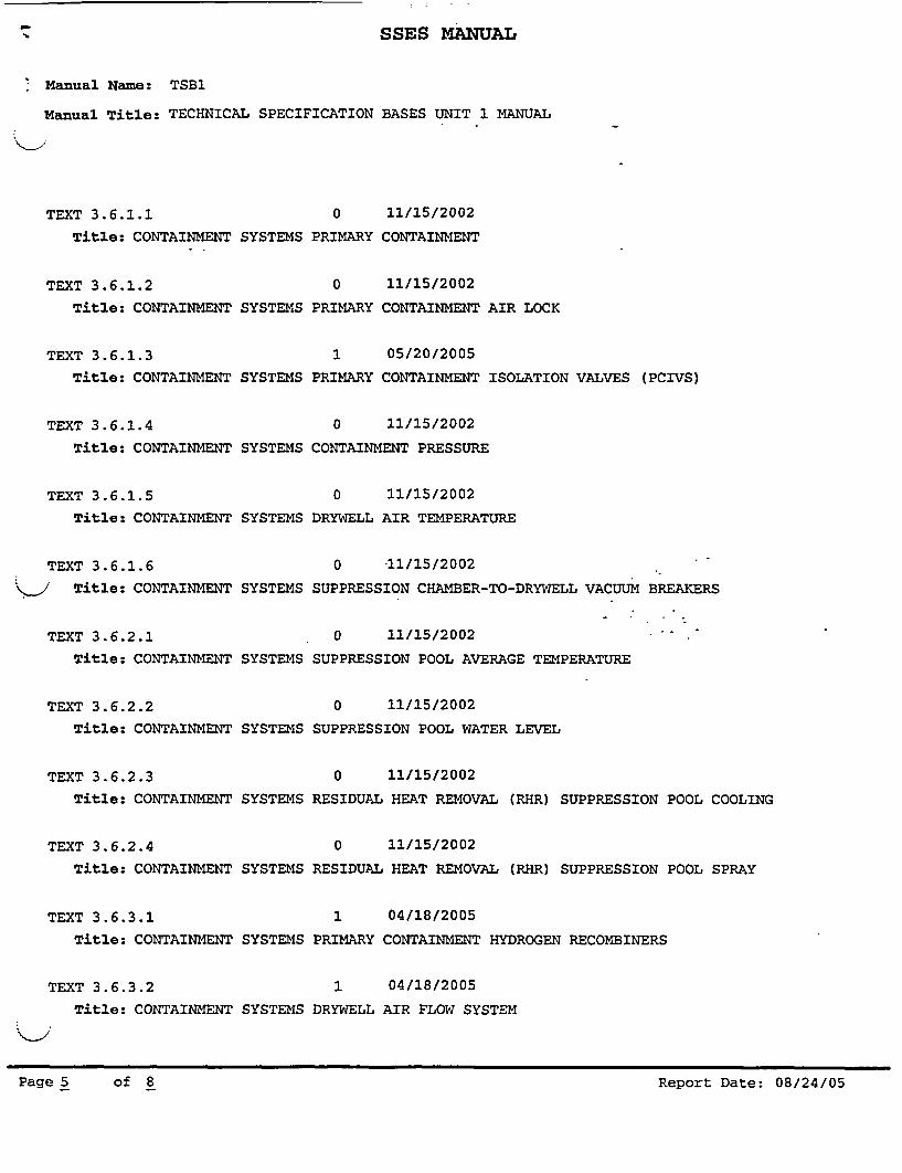
TEXT 3.6.1.1
Title: CONTAINMENT
TEXT 3.6.1.2
Title: CONTAINMENT
TEXT 3.6.1.3
Title: CONTAINMENT
TEXT 3.6.1.4
Title: CONTAINMENT
TEXT 3.6.1.5
Title: CONTAINMENT
TEXT 3.6.1.6
__/ Title: CONTAINMENT
TEXT 3.6.2.1
Title: CONTAINMENT
TEXT 3.6.2.2
Title: CONTAINMENT
TEXT 3.6.2.3
Title: CONTAINMENT
TEXT 3.6.2.4
Title: CONTAINMENT
TEXT 3.6.3.1
Title: CONTAINMENT
TEXT 3.6.3.2
Title: CONTAINMENT
0 11/15/2002
SYSTEMS PRIMARY CONTAINMENT
0 11/15/2002
SYSTEMS PRIMARY CONTAINMENT AIR LOCK
1 05/20/2005
SYSTEMS PRIMARY CONTAINMENT ISOLATION VALVES (PCIVS)
0 11/15/2002
SYSTEMS CONTAINMENT PRESSURE
0 11/15/2002
SYSTEMS DRYWELL AIR TEMPERATURE
0 11/15/2002
SYSTEMS SUPPRESSION CHAMBER-TO-DRYWELL VACUUM BREAKERS
0 11/15/2002
SYSTEMS SUPPRESSION POOL AVERAGE TEMPERATURE
0 11/15/2002
SYSTEMS SUPPRESSION POOL WATER LEVEL
0 11/15/2002
SYSTEMS RESIDUAL HEAT REMOVAL (RHR) SUPPRESSION POOL COOLING
0 11/15/2002
SYSTEMS RESIDUAL HEAT REMOVAL (RHR) SUPPRESSION POOL SPRAY
1 04/18/2005
SYSTEMS PRIMARY CONTAINMENT HYDROGEN RECOMBINERS
1 04/18/2005
SYSTEMS DRYWELL AIR FLOW SYSTEM
PageS of 8 Report Date: 08/24/05
Page 5 of 8 Report Date: 08/24/05

SSES MANUAL
-Manual Name: TSB1
Manual Title: TECHNICAL SPECIFICATION BASES UNIT 1 MANUAL
TEXT 3.6.3.3 0 11/15/2002
Title: CONTAINMENT SYSTEMS PRIMARY CONTAINMENT OXYGEN CONCENTRATION
TEXT 3.6.4.1 2 03/01/2005
Title: CONTAINMENT SYSTEMS SECONDARY CONTAINMENT
TEXT 3.6.4.2 2 01/03/2005
Title: CONTAINMENT SYSTEMS SECONDARY CONTAINMENT ISOLATION VALVES (SCIVS)
TEXT 3.6.4.3 2 11/09/2004
Title: CONTAINMENT SYSTEMS STANDBY GAS TREATMENT (SGT) SYSTEM
TEXT 3.7.1 0 11/15/2002
Title: PLANT SYSTEMS RESIDUAL HEAT REMOVAL SERVICE WATER (RHRSW) SYSTEM AND THEULTIMATE HEAT SINK (UHS)
TEXT 3.7.2
Title: PLANT
TEXT 3.7.3
Title: PLANT
TEXT 3.7.4
Title: PLANT
TEXT 3.7.5
Title: PLANT
TEXT 3.7.6
Title: PLANT
TEXT 3.7.7
Title: PLANT
TEXT 3.8.1
1 11/09/2004
SYSTEMS EMERGENCY SERVICE WATER (ESW) SYSTEM
0 11/15/2002
SYSTEMS CONTROL ROOM EMERGENCY OUTSIDE AIR SUPPLY (CREOAS) SYSTEM
0 11/15/2002
SYSTEMS CONTROL ROOM FLOOR COOLING SYSTEM
0 11/15/2002
SYSTEMS MAIN CONDENSER OFFGAS
1 01/17/2005
SYSTEMS MAIN TURBINE BYPASS SYSTEM
0 11/15/2002
SYSTEMS SPENT FUEL STORAGE POOL WATER LEVEL
2 04/18/2005
Title: ELECTRICAL POWER SYSTEMS AC SOURCES - OPERATING., --
Page6 of 8 Report Date: 08/24/05
Page 6 of 8 Report Date: 08/24/05

SSES MANUAL
: Manual Name: TSB1
Manual Title: TECHNICAL SPECIFICATION BASES UNIT 1 MANUAL
TEXT 3.8.2
Title: ELECTRICAL
TEXT 3.8.3
Title: ELECTRICAL
TEXT 3.8.4
Title: ELECTRICAL
0
POWER SYSTEMS
0
POWER SYSTEMS
0
POWER SYSTEMS
11/15/2002
AC SOURCES - SHUTDOWN
11/15/2002
DIESEL FUEL OIL, LUBE OIL, AND STARTING AIR
11/15/2002
DC SOURCES - OPERATING
TEXT 3.8.5
Title: ELECTRICAL
TEXT 3.8.6
Title: ELECTRICAL
TEXT 3.8.7
i Title: ELECTRICAL
TEXT 3.8.8
Title: ELECTRICAL
0 11/15/2002
POWER SYSTEMS DC SOURCES - SHUTDOWN
0 11/15/2002
POWER SYSTEMS BATTERY CELL PARAMETERS
0 11/15/2002
POWER SYSTEMS DISTRIBUTION SYSTEMS - OPERATING
0 11/15/2002
POWER SYSTEMS DISTRIBUTION SYSTEMS - SHUTDOWN
TEXT 3.9.1
Title: REFUELING
TEXT 3.9.2
Title: REFUELING
TEXT 3.9.3
Title: REFUELING
TEXT 3.9.4
Title: REFUELING
TEXT 3.9.5
Title: REFUELING
OPERATIONS
OPERATIONS
OPERATIONS
OPERATIONS
OPERATIONS
0 11/15/2002
REFUELING EQUIPMENT INTERLOCKS
0 11/15/2002
REFUEL POSITION ONE-ROD-OUT INTERLOCK
0 11/15/2002
CONTROL ROD POSITION
0 11/15/2002
CONTROL ROD POSITION INDICATION
0 11/15/2002
CONTROL ROD OPERABILITY - REFUELING
Page7 of 8 Report Date: 08/24/05
Page 7 of 8 Report Date: 08/24/05
SSES MANUAL
Manual Name: TSB1
Manual Title: TECHNICAL SPECIFICATION BASES UNIT 1 MANUAL
r
4
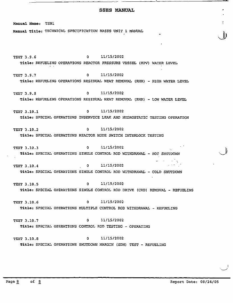
TEXT 3.9.6 0 11115/2002
Title: REFUELING OPERATIONS REACTOR PRESSURE VESSEL (RPV)
TEXT 3.9.7 0 11/15/2002
Title: REFUELING OPERATIONS RESIDUAL HEAT REMOVAL (RHR) -
TEXT 3.9.8 0 11/15/2002
Title: REFUELING OPERATIONS RESIDUAL HEAT REMOVAL (RHR) -
WATER LEVEL
HIGH WATER LEVEL
LOW WATER LEVEL
TEXT 3.10.1
Title: SPECIAL
0 11/15/2002
OPERATIONS INSERVICE LEAK AND HYDROSTATIC TESTING OPERATION
TEXT 3.10.2
Title: SPECIAL
TEXT 3.10.3
Title: SPECIAL
TEXT 3.10.4
Title: SPECIAL
TEXT 3.10.5
Title: SPECIAL
TEXT 3.10.6
Title: SPECIAL
TEXT 3.10.7
Title: SPECIAL
TEXT 3.10.8
Title: SPECIAL
OPERATIONS
OPERATIONS
OPERATIONS
OPERATIONS
OPERATIONS
OPERATIONS
OPERATIONS
0 11/15/2002
REACTOR MODE SWITCH INTERLOCK TESTING
0 11/15/2002
SINGLE CONTROL ROD WITHDRAWAL - HOT SHUTDOWN
0 11/15/2002 -
SINGLE CONTROL ROD WITHDRAWAL - COLD SHUTDOWN
0 11/15/2002
SINGLE CONTROL ROD DRIVE (CRD) REMOVAL - REFUELING
0 11/15/2002
MULTIPLE CONTROL ROD WITHDRAWAL - REFUELING
0 11/15/2002
CONTROL ROD TESTING - OPERATING
0 11/15/2002
SHUTDOWN MARGIN (SDM) TEST - REFUELING
J
Page8 of B Report Date: 08/24/05
Page 8 of 8 Report Date: 08/24/05

SUSQUEHANNA STEAM ELECTRIC STATIONUST OF EFFECTIVE SECTIONS (TECHNICAL SPECIFICATIONS BASES)
Section
TOC
Title
Table of Contents
-I Revision
7.
B2.0
B 3.0
' B3.1
SAFETY LIMITS BASESPage B 2.0-1PageTS/B2.0-2Page TS/B2.0-3Pages TS/ B 2.0-4 and TS / B 2.0-5PageTS/B2.0-6Pages B 2.0-7 through B 2.0-9
LCO AND SR APPLICABILITY BASESPages B 3.0-1 through B 3.0-4Pages TS / B 3.0-5 through TS / B 3.0-7Pages TS / B 3.0-8 through TS / B 3.0-9 /Pages TS / B 3.0-10 through TS / B 3.0-12\,,'Pages TS / B 3.0-13 through TS / B 3:.0-15 1Pages TS / B 3.0-16 and TS/ B 3.07.i7 ,7
REACTIVITY CONTROL BASES N ,1'4
Pages B 3.1-1 through B 3:1;5,Pages TS / B 3.1- andTS,/ B 3.--'Pages B 3.1-8 through B 3.1-13>,PageTS/B3.1-14,' " \ ;Pages B 3.1-15,tliroughB 31-22 -
Page TS/B31-23 \Pages B 3.1-24through B 3.1-27Page TS /1B,3.1-28':, 'Page 1TS i B 3.1-29Pages B 3.1-30'through B 3.1-33Pages TS /8 3.3-34 through TS / B 3.3-36
fPageTS /B 3.1-37('PageTS / B 3.1-38\ XPages B 3.1-39 through B 3.1-51
023.
.2I0.
It
0I2I20
*0
I0I0I0II01.2II
B3.2 POWER DISTRIBUTION LIMITS BASESPage TS / B 3.2-1Page TS / B 3.2-2Page TS / B 3.2-3Page TS / B 3.2-4Pages TS / B 3.2-5 and TS/B 3.2-6Page B 3.2-7Pages TS I B 3.2-8 through TS I B 3.2-10Page TS / B 3.2-11Page B 3.2-12Page TS / B 3.2-13Pages B 3.2-14 and B 3.2-15Page TS / B 3.2-16
1
21
12I0I
.21.0
202
SUSQUEHANNA - UNIT I TSIBLOES-1 Revision 62SUSQUEHANNA - UNIT 1 TS I B LOES-1 IRevision 62

SUSQUEHANNA STEAM ELECTRIC STATIONLIST OF EFFECTIVE SECTIONS (TECHNICAL SPECIFICATIONS BASES)
ISection Title
Pages B 3.2-17 and B 3.2-18Page TS / B 3.2-19
Revision
03
B 3.3 INSTRUMENTATIONPages TS / B 3.3-1 through TS / B 3.3-4Page TS / B 3.3-5PageTS/B3.3-6Pages TS / B 3.3-7 through TS / B 3.3-11Page TS / B 3.3-12PageTS/B3.3-13Page TS / B 3.3-14Pages TS / B 3.3-15 and TS / B 3.3-16Pages TS / B 3.3-17 and TS / B 3.3-18Pages TS / B 3.3-19 through TS / B 3.3-27Pages TS / B 3.3-28 through TS / B 3.3-31Pages TS / B 3.3-32 and TS / B 3.3-33Pages TS / B 3.3-34 through TS / B 3.3-43Pages TS / B 3.3-43a through TS I B 3.3-43iPages TS I B 3.3-44 through TS / B 3.3-50Pages TS I B 3.3-51 through TS / B 3.3-53Page TS / B 3.3-54Pages B 3.3-55 through .B 3.3-63Pages TS / B 3.3-64 and TS B 3.3-65Page'TS / B 3.3-66Page TS/B3.3-67Page TS / B 3.3-68Pages TS / B 3.3-69 and TS I B 3.3-70Page TS / B 3.3-71Pages TS / 3.3-72 through TS 3.3-75'Page TS / B 3.3-75aPages TS / B 3.3-75b and TS / B 3.3-75cPages B 3.3-76 through 3.3-77Page TS / B 3.3-78Pages B 3.3-79 through B 3.3-89Page TS / B 3.3-90Page B 3.3-91Page TS / B 3.3-92 through TS / B 3.3-1 00,Pages B 3.3-1 01 through B 3.3-103Page TS / B 3.3-104Pages B 3.3-105 and B 3.3-106PageTSI/B3.3-107Page B 3.3-108Page TS / B 3.3-109Pages B 3.3-110 and B 3.3-111Pages TS / B 3.3-112 and TS / B 3.3-112aPages TS / B 3.3-113 and TS / B 3.3-114Page TS / B 3.3-115
.12I2
I2I2
.1
4I02I2
* 02
* 4.- . . .3
4.3
32'440
01*�0I0I0I0
* I0I
*1I
SUSQUEHANNA - UNIT I IS/B LOES-2 Revision 62- SUSQUEHANNA -UNIT 1 TS / B LOES-2 Revision 62-
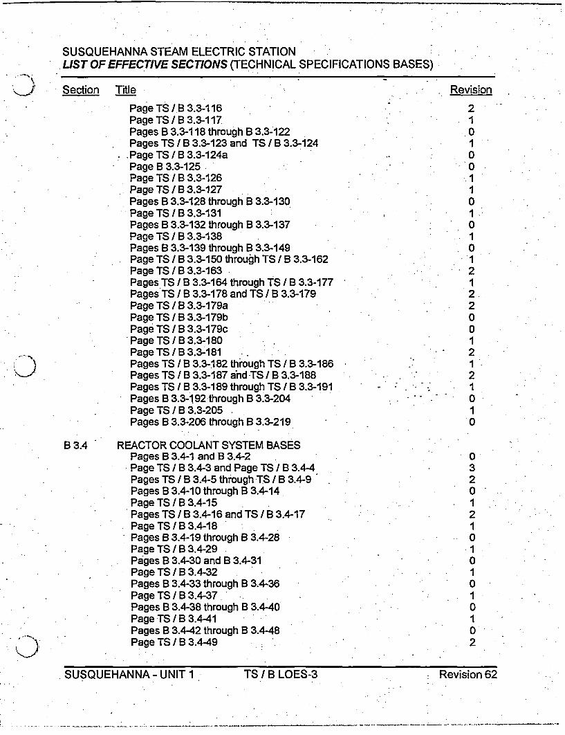
SUSQUEHANNA STEAM ELECTRIC STATIONLIST OF EFFECTIVE SECTIONS (TECHNICAL SPECIFICATIONS BASES)
Section Title
Page TS / B 3.3-116Page TS / B 3.3-117Pages B 3.3-118 through B 3.3-122Pages TS / B 3.3-123 and TS / B 3.3-124Page TS / B 3.3-124aPage B 3.3-125Page TS I B 3.3-126Page TS / B 3.3-127Pages B 3.3-128 through B 3.3-130Page TS / B 3.3-131Pages B 3.3-132 through B 3.3-137Page TS / B 3.3-138Pages B 3.3-139 through B 3.3-149Page TS / B 3.3-150 through TS / B 3.3-162Page TS / B 3.3-163Pages TS / B 3.3-164 through TS / B 3.3-177Pages TS / B 3.3-178 and TS / B 3.3-179Page TS / B 3.3-179aPage TS / B 3.3-179bPage TS / B 3.3-179cPage TS / B 3.3-180Page TS / B 3.3-181Pages TS I B 3.3-182 through TS I B 3.3-186Pages TS / B 3.3-187 and TS / B 3.3-188Pages TS / B 3.3-189 through TS / B 3.3-191Pages B 3.3-192:through B 3.3-204Page TS / B 3.3-205Pages B 3.3-206 through B 3.3-219
- . Revision
. .0
- .1- 2
- '.1
.,2
1*
2* ~ O
*0.' 1
0
B 3.4 REACTOR COOLANT SYSTEM BASESPages B 3.4-1 and B 3.4-2Page TS / B 3.4-3 and Page TS I B 3.4-4Pages TS / B 3.4-5 through TS / B 3.4-9Pages B 3.4-10 through B 3.4-14Page TS / B 3.4-15Pages TS / B 3.4-16 and TS / B 3.4-17Page TS / B 3.4-18Pages B 3.4-19 through B 3.4-28Page TS / B 3.4-29Pages B 3.4-30 and B 3.4-31Page TS /B 3.4-32Pages B 3.4-33 through B 3.4-36Page TS / B 3.4-37Pages B 3.4-38 through B 3.4-40Page TS / B 3.4-41Pages B 3.4-42 through B 3.4-48Page TS / B 3.4-49
O032
1 '.'21010
I 1* 0~
I010'2
SUSQUEHANNA-UNITi TS/BLOES-3 Revision 62- SUSQUEHANNA -UNIT 1- TS /B LOES-3 Revision 62

SUSQUEHANNA STEAM ELECTRIC STATIONLIST OF EFFECTIVE SECTIONS (TECHNICAL SPECIFICATIONS BASES)
.. Section Title
Page TS / B 3.4-50Page TS / B 3.4-51Pages TS / B 3.4-52 and TS I B 3.4-53Page TS / B 3.4-54Page TS / B 3.4-55Page TS / B 3.4-56Page TS/B3.4-57Pages TS / B 3.4-58 through TS / B 3.4-60
Revision
2I 122121.
B 3.5 ECCS AND RCIC BASESPages B 3.5-1 and B 3.5-2Page TS /B 3.5-3PageTS/B3.5-4PageTS/B3.5-5PageTSIB3.5-6Pages B 3.5-7 through B 3.5-10Page TS / B 3.5-11Pages B 3.5-12 through B 3.5-15Pages TS / B 3.5-16 through TS / B 3.5-18Pages B 3.5-19 through B 3.5-24Page TS / B 3.5-25Pages TS / B 3.5-26 andTSI B 3.5-27Pages B 3.5-28 through B 3.5-31
B 3.6 CONTAINMENT SYSTEMS BASESPage TS / B 3.6-1Page TS / B 3.6-1aPages TS / B 3.6-2 through TS I B 3.6-5Page TS I B 3.6-6Pages TS / B 3.6-6a and TS I B 3.6-6bPage TS / B 3.6-6cPages B 3.6-7 through B 3.6-14Page TS / B 3.6-15Pages TS / B 3.6-15a and TS I B 3.6-15bPage B 3.6-16Page TS B 3.6-17Page TS B 3.6-17aPagesTS/B3.6-18andTS/B3.6-19Page TS / B 3.6-20Page TS / B 3.6-21Page TS I B 3.6-22Page TS / B 3.6-22aPage TS /B 3.6-23Pages TS / B 3.6-24 through TS I B 3.6-25Page TS / B 3.6-26Page TS / B 3.6-27Page TS / B 3.6-28
021210.I01
011
0
2323.20
.0200100
*121
r0
01
25
.1
SUSQUEHANNA - UNIT I TSIBLOES-4 Revision 62SUSQUEHANNA - UNIT 1 ITS I B LOES-4 Revision 62

SUSQUEHANNA STEAM ELECTRIC STATIONLIST OF EFFECTIVE SECTIONS (TECHNICAL SPECIFICATIONS BASES)
Section Title
Page TSIB3.6-29Page TS I B 3.6-30Page TS / B 3.6-31Page B 3.6-32Page TS/B3.6-33Pages B 3.6-34 and B 3.6-35Page TS / B 3.6-36Page B 3.6-37Page TS/B3.6-38Page B 3.6-39Page TS / B 3.6-40Pages B 3.6-41 through B 3.6-43Pages TS / B 3.6-44 through TS / B 3.6-51Page TS / B 3.6-52Pages B 3.6-53 through B 3.6-63PageTS/B3.6-64Pages B 3.6-65 through B 3.6-72Page TS / B 3.6-73Pages B 3.6-74 through B 3.6-77Page TS/B3.6-78Pages B 3.6-79 through B 3.3.6-83Page TS / B 3.6-84Pages TS J B 3.6-85 and TS I B 3.6-86Pages TS / B 3.6-87 through TS / B 3.6-88aPage TS /B 3.6-89Page TS / B 3.6-90Page TS / B 3.6-91Pages TS / B 3.6-92 through TS /B 3.6-96Page TS / B 3.6-97Pages TS / B 3.6-98 and TS /B 3.6-99Page TS / B 3.6-100Pages TS / B 3.6-101 and TS / B 3.6-102Pages TS / B 3.6-103 through TS / B 3.6-105Pages TS / B 3.6-106 and TS / B 3.6-107
Revision
30
I0
I0.10.
0
320O1
321.3
.1.. 3.
3-2
- 2
2- *1
B3.7 PLANT SYSTEMS BASESPages TS / B 3.7-1 through TS / B 3.7-6Page TS / B 3.7-6aPagesTS / B 3 3.7-6b and TS / B 3.7-6cPage TS / B 3.7-7Pages TS / B 3.7-8 through TS / B 3.7-11Pages TS / B 3.7-12 and TS / B 3.7-13Pages TS / B 3.7-14 through TS / B 3.7-18Page TS / B 3.7-18aPages TS / B 3.7-19 through TS / B 3.7-23Pages B 3.7-24 through B 3.7-26Pages TS / B 3.7-27 through TS / B 3.7-29
22O
I 2I.120I ', . ..
4. J.
SUSQUEHANNA - UNIT 1 TS /B LOES-5* s
Re-vision 62

SUSQUEHANNA STEAM ELECTRIC STATIONUST OF EFFECTIVE SECTIONS (TECHNICAL SPECIFICATIONS BASES)
Section Title Revision
Page TS / B 3.7-30 2Pages B 3.7-31 through B 3.7-33 - 0
B 3.8 ELECTRICAL POWER SYSTEMS BASESPages TS J B 3.8-1 through TS / B 3.8-4 - 2Page TS / B 3.8-5 4Page TS I B 3.8-6 3Pages TS / B 3.8-7 through TS/B 3.8-8 *2Pages TS / B 3.8-9 and TS / B 3.8-10 3Pages TS / B 3.8-11 and TS/ B 3.8-17 2Page TS / B 3.8-18 3Pages TS / B 3.8-19 through TS I B 3.8-21 2Pages TS I B 3.8-22 and TS / B 3.8-23 3Pages TS / B 3.8-24 through TS / B 3.8-37 2Pages B 3.8-38 through B 3.8-53 0Pages TS / B 3.8-54 through TS I B 3.8-61 1.Page TS / B 3.8-62 - 2PageTS/B 3.8-63 -2Page TS / B 3.8-64 1Page TS / B 3.8-65 2Pages B 3.8-66 through B 3.8-90 0
B 3.9 REFUELING OPERATIONS BASESPages TS/ B 3.9-1 and TS B 3.9-1a a 1Pages TS / B 3.9-2 through TS / B 3.9-4 - 1
- Pages B 3.9-5 through B 3.9-30 . 0
B 3.10 SPECIAL OPERATIONS BASESPageTS/B3.10-1 -Pages B 3.10-2 through B 3.10-31 0Page TS / B 3.10-32 1Pages B 3.10-33 through B 3.10-37 0PageTS/B3.10-38 -
TSB1 texd LOES8/12/05
SUJSQUEHANNA - UNIT I TS/I B LOES-6 Revision 62

PPL Rev. 2PCIVs
B 3.6.1.3B 3.6 CONTAINMENT SYSTEMS
B 3.6.1.3 Primary Containment Isolation Valves (PCIVs)
BASES
BACKGROUND The function of the PCIVs, in combination with other accidentmitigation systems, is to limit fission product release during andfollowing postulated Design Basis Accidents (DBAs) to withinlimits. Primary containment isolation within the time limitsspecified for those isolation valves designed to close automaticallyensures that the release of radioactive material to the environmentwill be consistent with the assumptions used in the analyses for aDBA.
The OPERABILITY requirements for PCIVs help ensure that anadequate primary containment boundary is maintained during andafter an accident by minimizing potential paths to the environment.Therefore, the OPERABILITY requirements provide assurancethat primary containment function assumed in the safety analyseswill be maintained. For PCIVs, the primary containment isolationfunction is that the valve must be able to close (automatically ormanually) and/or remain closed, and maintain leakage within thatassumed in the DBA LOCA Dose Analysis. These isolationdevices are either passive or active (automatic); Manual valves,de-activated automatic valves secured in their closed position(including check valves with flow through the valve secured), blindflanges, and closed systems are considered passive devices. The'OPERABILITY requirements for closed systems are discussed inTechnical Requirements Manual (TRM) Bases 3.6.4. Checkvalves, or other automatic valves designed to close withoutoperator action following an accident, are considered activedevices. Two barriers in series are provided for each penetrationso that no single credible failure or malfunction of an activecomponent can result in a loss of isolation or leakage thatexceeds limits assumed in the safety analyses. One of thesebarriers may be a closed system.
For each division of H202 Analyzers, the lines, up to andincluding the first normally closed valves within the H202 Analyzerpanels, are extensions of primary containment (i.e.,closed system), and are required to be leak rate tested in
(continued)
SUSQUEHANNA - UNIT I TS / B 3.6-15 Revision 2.. . . . .

PPL Rev. 2PCIVs
-'B 3.6.1.3BASES I
'.X, BACKGROUND(continued)
accordance with the Leakage Rate Test Program. The H202Analyzer closed system boundary is identified in the LeakageRate Test Program. The closed system boundary consists ofthose components, piping, tubing, fittings, and valves, which meetthe guidance of Reference 6. The closed system provides asecondary barrier in the event of a single failure of the PCIVs, asdescribed below. The closed system boundary between PASSand the H202 Analyzer system ends at the process samplingsolenoid operated isolation valves between the systems (SV-12361, SV-12365, SV-12366, SV-12368, and SV-12369). Thesesolenoid operated isolation valves do not fully meet the guidanceof Reference 6 for closed system boundary valves in that they arenot powered from a Class 1 E power source. However, basedupon a risk determination, operating these valves as closedsystem boundary valves is not risk significant. These valves alsoform the end of the Seismic Category I boundary between the.systems. These process sampling solenoid operated isolationvalves are normally closed and are required to be leak rate testedin accordance with the Leakage Rate Test Program as part of theclosed system for the H202 Analyzer system. These valves areMclosed system boundary valves" and may be opened underadministrative control, as delineated in Technical RequirementsManual (TRM) Bases 3.6.4. Opening of these valves to permittesting of PASS in Modes 1, 2, and 3 is permitted in accordancewith TRO 3.6.4.
Each H202 Analyzer Sampling line penetrating primarycontainment has two PCIVs, located just outside primary.containment While two PCIVs are provided on each line, a singleactive failure of a relay in the control circuitry for these valves,could result in both valves failing to close or failing to remainclosed. Furthermore, a single failure (a hot short in the commonraceway to all the valves) could simultaneously affect all of thePCIVs within a H202 Analyzer division. Therefore, thecontainment isolation barriers for these penetrations consist of two'PCIVs and a closed system. For situations where one or bothPCIVs are inoperable, the ACTIONS to be taken are similar to theACTIONS for a single PCIV backed by a closed system.
(continued)
SUSQUEHANNA- UNIT 1 TS / B 3.6-15a Revision 0
----- �.---.------.---*-.-�--*-- ----

PPL Rev. 2PCIVs
B 3.6.1.3BASES - --
BACKGROUND(continued)
The drywell vent and purge lines are 24 inches in diameter;the suppression chamber vent and purge lines are 18 inches indiameter. The containment purge valves are normally maintainedclosed in MODES 1, 2, and 3 to ensure the primary containmentboundary is maintained. The outboard isolation valves have2 inch bypass lines around them for use during normal reactoroperation.
& j-I
(continued) -
SUSQUEHANNA- UNIT 1 TS / B 3.6-15b Revision 0
- I

PPL Rev. 2PCIVs
B 3.6.1.3BASES (continued)
APPLICABLE The PCIVs LCO was derived from the assumptions relatedSAFETY ANALYSES to minimizing the loss of reactor coolant inventory, and
establishing the primary containment boundary during majoraccidents. As part of the primary containment boundary, PCIVOPERABILITY supports leak tightness of primary containment.Therefore, the safety analysis of any event requiring isolation ofprimary containment is applicable to this LCO.
The DBAs that result in a release of radioactive material withinprimary containment are a LOCA and a main steam line break(MSLB). In the analysis for each of these accidents, it is assumedthat PCIVs are either closed or close within the required isolationtimes following event initiation. This ensures that potential paths to,the environment through PCIVs (including primary containment purgevalves) are minimized. Of the events analyzed in Reference 1, the.MSLB is the most limiting event due to radiological consequences.The closure time of the main steam isolation valves (MSIVs) is asignificant variable from a radiological standpoint. The MSIVs arerequired to close within 3 to 5 seconds since the 5 second closuretime is assumed in the analysis. The safety analyses assume that thepurge valves were closed at event initiation. Likewise, it is assumed.that the primary containment is isolated such that release of fissionproducts to the environment is controlled.
The DBA analysis assumes that within the required isolation timeleakage is terminated, except for the-maximum allowable leakagerate, L-.
The single failure criterion required to be imposed in the conductof unit safety analyses was considered in the original design of theprimary containment purge valves. Two valves in series on eachpurge line provide assurance that both the supply and exhaustlines could be isolated even if a single failure occurred.
The primary containment purge valves may be unable to close inthe environment following a LOCA. Therefore, each of the purgevalves is required to remain closed during MODES 1, 2, and 3except as permitted under Note 2 of SR 3.6.1.3.1. In this case,the single failure criterion remains applicable to the primarycontainment purge valve
(continued)
SUSQUEHANNA -UNITI1 B 3.6-1 Revision 0,
_ _ __ _

PPL Rev. 2PCI Vs
B 3.6.1.3BASES
APPLICABLE due to failure in the control circuit associated with eachSAFETY ANALYSES valve. The primary containment purge valve design(continued) precludes a single failure from compromising the primary
containment boundary as long as the system is operated inaccordance with this LCO.
Both H202 Analyzer PCIVs may not be able to close given a singlefailure in the control circuitry of the valves. The single failure iscaused by a "hot short" in the cables/raceway to the.PCIVs thatcauses both PCIVs for a given penetration to remain open or toopen when required to be closed. This failure is required to beconsidered in accordance with IEEE-279 as discussed in FSARSection 7.3.2a. However, the single failure criterion forcontainment isolation of the H202 Analyzer penetrations issatisfied by virtue of the combination of the associated PCIVs andthe closed system formed by the H202 Analyzer. piping system asdiscussed in the BACKGROUND section above.
The closed system boundary between PASS and the H202Analyzer system ends at the process sampling solenoid operatedisolation valves between the systems (SV-12361, SV-12365, SV-12366, SV-12368, and SV-12369). The closed system is not fullyqualified to the guidance of Reference 6 in that the closed systemboundary valves between the H202 system and PASS are notpowered from a Class 1 E power source. However, based upon arisk determination, the use of these valves is considered to haveno risk significance. This exemption to the requirement ofReference 6 for the closed system boundary is documented inLicense Amendment No. 195.
PCIVs satisfy Criterion 3 of the NRC Policy Statement. (Ref. 2)
LCO PCIVs form a part of the primary containment boundary. ThePCIV safety function is related to minimizing the loss of reactorcoolant inventory and establishing the primary containment
- boundary during a DBA.
The power operated, automatic isolation valves are required tohave isolation times within limits and actuate on an automaticisolation signal. The valves covered by this LCO are listed inTable B 3.6.1.3-1. .
(continued)
SUSQUEHANNA - UNIT I TS IB 3.6-17 Revision I

PPL Rev. 2PCIVs
- B 3.6.1.3BASES
LCO(continued)
The normally closed PCIVs are considered OPERABLEwhen manual valves are closed or open in accordance withappropriate administrative controls, automatic valves are in theirclosed position, blind flanges are in place, and closed systems areintact These passive isolation valves and devices are those listedin Table B 3.6.1.3-1.
-Purge valves with resilient seals, secondary containment bypassvalves, MSIVs, and hydrostatically tested valves must meetadditional leakage rate requirements. Other PCIV leakage ratesare addressed by LCO 3.6.1.1, "Primary Containment," as Type Bor C testing.
This LCO provides assurance that the PCIVs will pefom theirdesigned safety functions to minimize the loss of reactor coolantinventory and establish the primary containment boundary duringaccidents.
APPLICABILITY In MODES 1, 2, and 3, a DBA could cause a release ofradioactive material to primary containment. In MODES 4 and 5,the probability and consequences of these events are reduceddue to the pressure and temperature limitations of these MODES.Therefore, most PCIVs are not required to be
SUSQUEHANNA -UNIT 1I - TS/B3.6-17a(continued)Revision 0
PPL Rev. 2PCIVs
BASESB 3.6.1.3~BASES
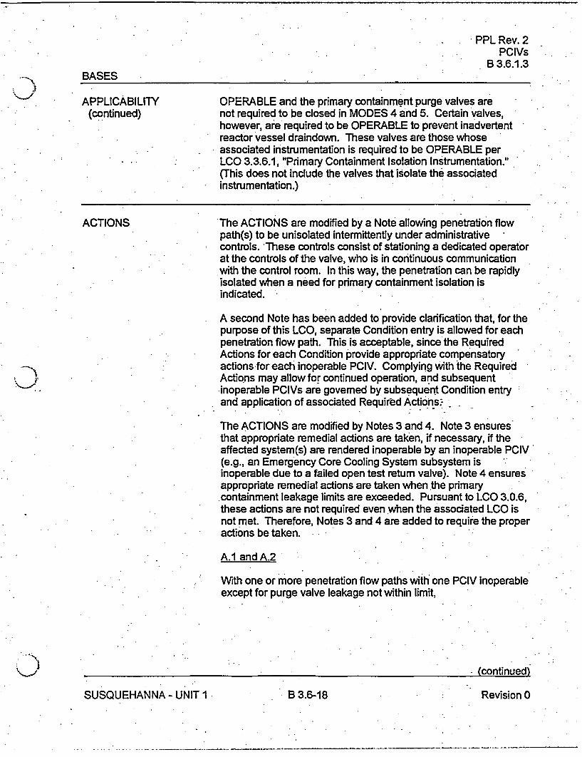
APPLICABILITY OPERABLE and the primary containment purge valves are(continued) not required to be closed in MODES 4 and 5. Certain valves,
however, are required to be OPERABLE to prevent inadvertentreactor vessel draindown. These valves are those whoseassociated instrumentation is required to be OPERABLE perLCO 3.3.6.1, "Primary Containment Isolation Instrumentation."(This does not include the valves that isolate the associatedinstrumentation.)
ACTIONS The ACTIONS are modified by a Note allowing penetration flowpath(s) to be unisolated intermittently under administrativecontrols. These controls consist of stationing a dedicated operatorat the controls of the valve, who is in continuous communicationwith the control room. In this way, the penetration can be rapidlyisolated when a need for primary containment isolation isindicated.
A second Note has been added to provide clarification that, for thepurpose of this LCO, separate Condition entry is allowed for eachpenetration flow path. This is acceptable, since the RequiredActions for each Condition provide appropriate compensatory
: actions-for each inoperable PCIV. Complying with the RequiredActions may allow for continued operation, and subsequentinoperable PCIVs are governed by subsequent Condition entryand application of associated Required Actions.
The ACTIONS are modified by Notes 3 and 4. Note 3 ensuresthat appropriate remedial actions are taken, if necessary, if theaffected system(s) are rendered inoperable by an inoperable PCIV'(e.g., an Emergency Core Cooling System subsystem isinoperable due to a failed open test return valve). Note 4 ensuresappropriate remedial actions are taken when the primarycontainment leakage limits are exceeded. Pursuant to LCO 3.0.6,these actions are not required even when the associated LCO isnot met. Therefore, Notes 3 and 4 are added to require the properactions be taken.
A.1 and A.2
With one or more penetration flow paths with one PCIV inoperableexcept for purge valve leakage not within limit,
) ' (continued)
SUSQUEHANNA -UNIT 1 B 3.6-18 Revision 0
-------

PPL Rev. 2PCIVs
B 3.6.1.3BASES
ACTIONS A.1 and A.2 (continued)
the affected penetration flow paths must be isolated. The method ofisolation must include the use of at least onelisolation barrier that cannotbe adversely affected by a single active failure. Isolation barriers thatmeet this criterion are a closed and de-activated automatic valve, aclosed manual valve, a blind flange, and a check valve with flow throughthe valve secured. For a penetration isolated in accordance withRequired Action A.1, the device used to isolate the penetration should bethe closest available valve to the primary containment. The' RequiredAction must be completed within the 4 hour Completion Time (8 hours formain steam lines). The Completion Time of 4 hours is reasonableconsidering the time required to isolate the penetration and the relativeimportance of supporting primary containment OPERABILITY duringMODES 1, 2, and 3. For main steam lines, an 8 hour Completion Time isallowed. The Completion Time of 8 hours for the main steam lines allowsa period of time to restore the MSIVs to OPERABLE status given the factthat MSIV closure will result in isolation of the main steam line(s) and apotential for plant shutdown.
For affected penetrations that have been isolated in accordance withRequired Action A.1, the affected penetration flow path(s) must beverified to be isolated on a periodic basis. This is necessary to ensurethat primary containment penetrations required to be isolated following anaccident, and no longer capable of being automatically isolated, will be inthe isolation position should an event occur: This Required Action doesnot require any testing or device manipulation. Rather, it involvesverification that those devices outside containment and capable ofpotentially being mispositioned are in the.correct position. TheCompletion Time of "once per 31 days for isolation devices outsideprimary containment" is appropriate because the devices are operatedunder administrative controls and the probability of their misalignment islow. For the devices inside primary containment, the time periodspecified "prior to entering MODE 2 or 3 from MODE 4, if primarycontainment was de-inerted while in MODE 4, if not performed within theprevious 92 days" is based on engineering judgment and is consideredreasonable in view of the inaccessibility of the devices and otheradministrative controls ensuring that device misalignment is an unlikelypossibility.
(continued)
SUSQUEHANNA - UNIT I B 3.6-19 Revision 0

PPL Rev. 2PCIVs
B 3.6.1.3BASES
ACTIONS A.1 and A.2 (continued)
Condition A is modified by a Note indicating that this Condition isonly applicable to those penetration flow paths with two PCIVsexcept for the H202 Analyzer penetrations.For penetration flow paths with one PCIV, Condition C providesthe appropriate Required Actions. Forthe H202 AnalyzerPenetrations, Condition D provides the appropriate RequiredActions.
Required Action A.2 is modified by a Note that applies to isolationdevices located in high radiation areas, and allows them to beverified by use of administrative means. Allowing verification byadministrative means is considered acceptable, since access tothese areas is typically restricted. Therefore, the probability ofmisalignment of these devices, once they have been verified to bein the proper position, is low.
BA1
With one or more penetration flow paths with two PCIVsinoperable except for purge valve leakage not within limit, eitherthe inoperable PCIVs must be restored to OPERABLE status orthe affected penetration flow path must be isolated within 1 hour.The method of isolation must include the use of at least oneisolation barrier that cannot be adversely affected by a singleactive failure. Isolation barriers that meet this'criterion are aclosed and de-activated automatic valve, a closed manual valve,and a blind flange. The 1 hour Completion Time is consistent withthe ACTIONS of LCO 3.6.1.1.
Condition B is modified by a Note indicating this Condition is onlyapplicable to penetration flow paths with two PCIVs except for theH202 Analyzer penetrations. For penetration flow paths with onePCIV, Condition C provides the appropriate Required Actions. Forthe H202 Analyzer Penetrations, Condition D provides theappropriate Required Actions.
C.1 and C.2
With one or more penetration flow paths with one PCIVinoperable, the inoperable valve must be restored to OPERABLEstatus or the affected penetration flow path
(continued)
SUSQUEHANNA - UNIT 1 TS IB 3.6-20 Revision I

PPL Rev. 2PCIVs
B 3.6.1.3BASES
ACTIONS C.1 and C.2 (continued)
must be isolated. The method of isolation must include the use ofat least one isolation barrier that cannot be adversely affected bya single active failure. Isolation barriers that meet this criterion area closed and de-activated automatic valve, a closed manual valve,and a blind flange. A check valve may not be used to isolate theaffected penetration. Required Action C.1 must be completedwithin the 72 hour Completion Time. The Completion Time of72 hours is reasonable considering the relative stability of theclosed system (hence, reliability) to act as a penetration isolationboundary and the relative importance of supporting primarycontainment OPERABILITY during MODES 1, 2, and 3. Theclosed system must meet the requirements of Reference 6. Forconditions where the PCIV and the closed system are inoperable,the Required Actions of TRO 3.6.4, Condition B apply. For theExcess Flow Check Valves (EFCV), the Completion Time of12 hours is reasonable considering the instrument and the smallpipe diameter of penetration (hence, reliability) to act as apenetration isolation boundary and the small pipe diameter of theaffected penetrations. In the event the affected penetration flowpath is isolated in accordance with Required Action C.1, theaffected penetration must be verified to be isolated on a periodicbasis. This is necessary to ensure that primary containment-penetrations required to be isolated following an accident areisolated. The Completion Time of once per 31 days for verifyingeach affected penetration is isolated is appropriate because thevalves are operated under administrative controls and theprobability of their misalignment is. low.
Condition C is modified by a Note indicating that this Condition isonly applicable to penetration flow paths with only one PCIV. Forpenetration flow paths with two PCIVs and the H202 AnalyzerPenetration. Conditions A, B and D provide the appropriateRequired Actions.
Required Action C.2 is modified by a Note that applies to valvesand blind flanges located in high radiation areas and allows themto be verified by use of administrative means. Allowing verificationby administrative means is considered acceptable, since accessto these areas is typically restricted. Therefore, the probability ofmisalignment of these valves, once they have been verified to bein the proper position, is low.
(continued)
SUSQUEHANNA - UNIT I TS / B 3.6-21 Revision 2

PPL Rev. 2:PCIVs
B 3.6.1.3BASES
ACTIONS D.l and D.2(continued)
With one or more H202 Analyzer penetrations with one or bothPCIVs inoperable, the inoperable valve(s) must be restored toOPERABLE status or the affected penetration flow path must beisolated. The method of isolation must include the use of at leastone isolation barrier that cannot be adversely affected by a singleactive failure. Isolation barriers that meet this criterion are aclosed and de-activated automatic valve, a closed manual valve,and a blind flange. A check valve may not be used to isolate theaffected penetration. Required Action D.1 must be completed.within the 72 hour Completion Time. The Completion Time of72 hours is reasonable considering the unique design of the H202Analyzer penetrations. The containment isolation barriers forthese penetrations consist of two PCIVs and a closed system. Inaddition, the Completion Time of 72 hours is reasonableconsidering the relative stability of the closed system (hence,reliability) to act as a penetration isolation boundary and therelative importance of supporting primary containmentOPERABILITY during MODES 1, 2, and 3. In the event theaffected penetration flow path is isolated in accordance withRequired Action D.1, the affected penetration must be verified tobe isolated on a periodic basis. This is necessary to ensure thatprimary containment penetrations required to be isolated followingan accident are isolated. The Completion Time of once per31 days for verifying each affected penetration is isolated isappropriate because the valves are operated under administrativecontrols and the probability of their misalignment is low.
When an H202 Analyzer penetration PCIV is to be closed anddeactivated in accordance with Condition D, this must beaccomplished by pulling the fuse for the power supply, and eitherdeterminating the power cables at the solenoid valve, or jumperingof the power side of the solenoid to ground.
The OPERABILITY requirements for the closed system arediscussed in Technical Requirements Manual (TRM) Bases 3.6.4.In the event that either one or both of the PCIVs and the closedsystem are inoperable, the Required Actions of TRO 3.6.4,Condition B apply.
(continued)'
SUSQUEHANNA - UNIT I TS IB 3.6-22 Revision I

PPL Rev. 2PCI Vs
B 3.6.1.3BASES
ACTIONS D.1 and D.2 (continued)
Condition D is modified by a Note indicating that this Condition isonly applicable to the H202 Analyzer penetrations.
E.1
With the secondary containment bypass leakage rate not withinlimit, the assumptions of the safety analysis may not be met.Therefore, the leakage must be restored to within limit within4 hours. Restoration can be accomplished by isolating thepenetration that caused the limit to be exceeded by use of oneclosed and de-activated automatic valve, closed manual valve, orblind flange. When a penetration is isolated, the leakage rate forthe isolated penetration is assumed to be the actual pathwayleakage through the isolation device. If two isolation devices areused to isolate the penetration, the leakage rate is assumed to bethe lesser actual pathway leakage of the two devices. The 4 hourCompletion Time is reasonable considering the time required torestore the leakage by isolating the penetration and the relativeimportance of secondary containment bypass leakage to theoverall containment function.
F.1*
In the event one or more containment purge -valves are not withinthe purge valve leakage limits, purge valve 16tikage must berestored to within limits. The 24 hour Completion Time isreasonable, considering that one containment purge valveremains closed, except as controlled by SR 3.6.1.3.1 so that agross breach of containment does not exist
G.1 and G.2
If any Required Action and associated Completion Time cannot bemet in MODE 1, 2, or 3, the plant must be brought to a MODE inwhich the LCO does not apply. To achieve this status, the plantmust be brought to at least MODE 3 within 12 hours and toMODE 4 within 36 hours. The allowed Completion Times arereasonable, based on operating experience, to reach the requiredplant conditions from full power conditions in an orderly mannerand without challenging plant systems.
(continued)
SUSQUEHANNA'- UNIT I TS IB 3.6-22a Revision 0

PPL Rev. 2-PCIVs
B 3.6.1.3IBASES
ACTIONS(continued)
H.1 and H.2
If any Required Action and associated Completion Time cannot bemet, the unit must be placed in a condition in which the LCO doesnot apply. If applicable, action must be immediately initiated tosuspend operations with a potential for draining the reactor vessel(OPDRVs) to minimize the probability of a vessel draindown andsubsequent potential for fission product release. Actions mustcontinue until OPDRVs are suspended or valve(s) are restored toOPERABLE status. If suspending an OPDRV would result inclosing the residual heat removal (RHR) shutdown coolingisolation valves, an alternative Required Action is provided toimmediately initiate action to restore the valve(s) to OPERABLEstatus. This allows RHR to remain in service while actions arebeing taken to restore the valve.
SURVEILLANCEREQUIREMENTS
SR 3.6.1.3.1
This SR ensures that the primary containment purge valves areclosed as required or, if open, open for an allowable reason. If apurge valve is open in violation of this SR, the valve is consideredinoperable. If the inoperable valve is not otherwise known to haveexcessive leakage when closed, it is not considered to haveleakage outside of limits. The SR is also modified by Note 1,stating that primary containment purge valves are only required tobe closed in MODES 1, 2, and 3. If a LOCA inside primarycontainment occurs in these MODES, the purge valves may notbe capable of closing before the pressure pulse affects systemsdownstream of the purge valves, or the release of radioactivematerial will exceed limits prior to the purge valves closing. Atother times when the purge valves are required to be capable ofclosing (e.g., during handling of irradiated fuel), pressurizationconcerns are not present and the purge valves are allowed to beopen. The SR is modified by Note 2 stating that the SR is notrequired to be met when the purge valves are open for the statedreasons. The Note states that these valves may be opened forinerting, de-inerting, pressure control, ALARA or air qualityconsiderations for personnel entry, or Surveillances that requirethe valves to be open. The vent and purge valves are capable ofClosing in the environment following a LOCA. Therefore, thesevalves are allowed to be open for
(continued)
SUSQUEHANNA- UNIT I -TS / B3.6-23 Revision 1

PPL Rev. 2PCIVs
B 3.6.1.3BASES
SURVEILLANCE SR 3.6.1.3.1 (continued)REQUIREMENTS
limited periods of time. The 31 day Frequency is consistent withother PCIV requirements discussed in SR 3.6.1.3.2.
SR 3.6.1.3.2
This SR verifies that each primary containment isolation manualvalve and blind flange that is located outside primary containmentand not locked, sealed, or otherwise secured and is required to beclosed during accident conditions is closed. The SR helps toensure that post accident leakage of radioactive fluids or gasesoutside the primary containment boundary is within design limits.
This SR does not require any testing or valve manipulation.Rather, it involves verification that those PCIVs outside primarycontainment, and capable of being mispositioned, are in thecorrect position. Since verification of valve position for PCIVsoutside primary containment is relatively easy, the 31 dayFrequency was chosen to provide added assurance that thePCIVs are in the correct positions.
Two Notes have been added to this SR. The first Note allowsvalves and blind flanges located in high radiation areas to be
-I , - verified by use of administrative controls. Allowing verification byadministrative controls is considered-acceptable since access tothese areas is typically restricted during MODES 1, 2, and 3 forALARA reasons. Therefore, the probability of misalignment ofthese PCIVs, once they have been verified to be in the proper
- position, is low. A second Note has been included to clarify thatPCIVs that are open under administrative controls are not requiredto meet the SR during the time that the PCIVs are open. This SRdoes not apply to valves that are locked, sealed, or otherwisesecured in the closed position, since these were verified to be inthe correct position upon locking, sealing, or securing.
SR 3.6.1.3.3
This SR verifies that each primary containment manual isolationvalve and blind flange that is located inside primary containmentand not locked, sealed, or otherwise
(continued)
SUSQUEHANNA - UNIT . B 3.6-24 Revision 0

PPL Rev. 2PCIVs
B 3.6.1.3BASES
SURVEILLANCEREQUIREMENTS
SR 3.6.1.3.3 (continued)
secured and is required to be closed during accident conditions isclosed. The SR helps to ensure that post accident leakage ofradioactive fluids or gases outside the primary containmentboundary is within design limits. For PCIVs inside primarycontainment, the Frequency defined as "prior to entering MODE 2or 3 from MODE 4 if primary containment was de-inerted while inMODE 4, if not performed within the previous 92 days" isappropriate since these PCIVs are operated under administrativecontrols and the probability of their misalignment is low. This SRdoes not apply to valves that are locked, sealed, or otherwisesecured in the closed position, since these were verified to be inthe correct position upon locking, sealing, or securing. Two Noteshave been added to this SR. The first Note allows valves andblind flanges located in high radiation areas to be verified by useof administrative controls. Allowing verification by administrativecontrols is considered acceptable since the primary containment isinerted and access to these areas is typically restricted duringMODES 1, 2, and 3 for ALARA reasons. Therefore, theprobability of misalignment of these PCIVs, once they have beenverified to be in their proper position, is low. A second Note hasbeen included to clarify that PCIVs that are open underadministrative controls are not required to meet the SR during thetime that the PCIVs are open.
SR 3.6.1.3.4
The traversing incore probe (TIP) shear isolation valves areactuated by explosive charges. Surveillance of explosive chargecontinuity provides assurance that TIP valves will actuate whenrequired. Other administrative controls, such as those that limitthe shelf life of the explosive charges, must be followed. The31 day Frequency is based on operating experience that hasdemonstrated the reliability of the explosive charge continuity.
SR 3.6.1.3.5
Verifying the isolation time of each power operated and eachautomatic PCIV is within limits is required to demonstrateOPERABILITY. MSIVs may be excluded from this SR sinceMSIV
(continued)0DSUSQUEHANNA - UNIT I BIB 3.6-25 Revisio~n 0

PPL Rev. 2PCIVs
B 3.6.1.3BASES
SURVEILLANCE SR 3.6.1.3.5 (continued) 'REQUIREMENTS
full closure isolation time is demonstrated by SR 3.6.1.3.7. Theisolation time test ensures that the valve will isolate in a time periodless than or equal to that assumed in the Final Safety AnalysesReport. The isolation time and Frequency of this SR are inaccordance with the requirements of the Inservice TestingProgram.
SR 3.6.1.3.6
For primary containment purge valves with resilient seals, theAppendix J Leakage Rate Test Interval of 24 months is sufficient.The acceptance criteria for these valves is defined in the PrimaryContainment Leakage Rate Testing Program, 5.5.12.
The SR is modified by a Note stating that the primary'containmentpurge valves are only required to meet leakage rate testingrequirements in MODES 1, 2, and 3. If a LOCA inside primarycontainment occurs in these MODES, purge valve leakage mustbe minimized to ensure offsite radiological release is within limits.At other times when the purge valves are required to be capableof closing (e.g., during handling of irradiated fuel); pressurizationconcerns are not present and the purge valves are not required tomeet any specific leakage criteria.
SR 3.6.1.3.7
Verifying that the isolation time of each MSIV is within the specifiedlimits is required to demonstrate OPERABILITY. The isolation time
-test ensures that the MSIV will isolate in a time period that does notexceed the times assumed in the DBA analyses. This ensures thatthe calculated radiological consequences of these events remainwithin 10 CFR 100 limits. The Frequency of this SR is inaccordance with the requirements of the Inservice Testing Program.
(continued)
SUSQUEHANNA - UNIT I TS B 3.6-26 Revision I

PPL Rev. 2PCIVs
B 3.6.1.3BASES
SURVEILLANCEREQUIREMENTS(continued)
SR 3.6.1.3.8
Automatic PCIVs close on a primary containment isolation signalto prevent leakage of radioactive material from primarycontainment following a DBA. This SR ensures that eachautomatic PCIV will actuate to its isolation position on a primarycontainment isolation signal. The LOGIC SYSTEM FUNCTIONALTEST in SR 3.3.6.1.5 overlaps this SR to provide complete testingof the safety function. The 24 month Frequency was developedconsidering it is prudent that some of these Surveillances beperformed only during a unit outage since isolation of penetrationscould eliminate cooling water flow and disrupt the normaloperation of some critical components. Operating experience hasshown that these components usually pass this Surveillance whenperformed at the 24 month Frequency. Therefore, the Frequencywas concluded to be acceptable from a reliability standpoint
SR 3.6.1.3.9
This SR requires a demonstration that a representative sample ofreactor instrumentation line excess flow check valves (EFCV) areOPERABLE by verifying that the valve actuates to check flow on asimulated instrument line break. As defined in FSAR Section6.2.4.3.5 (Reference 4), the conditions under which an EFCV willisolate, simulated instrument line break, are at flow rates whichdevelop a differential pressure of between 3 psld and 10 psid.This SR provides assurance that the instrumentation line EFCVswill perform its design function to check flow. No specific valveleakage limits are specified because no specific leakage limits aredefined in the FSAR. The 24 month Frequency is based on theneed to perform some of these Surveillances under the conditionsthat apply during a plant outage and the potential for anunplanned transient if the Surveillance were performed with thereactor at power. The representative sample consists of anapproximate equal number of EFCVs such that each EFCV istested at least once every 10 years (nominal). The nominal10 year interval is based on other performance-based testingprograms, such as Inservice Testing (snubbers) and Option B to10 CFR 50, Appendix J. In addition, the EFCVs in the sample arerepresentative of the various plant configurations, models, sizesand operating environments. This ensures that any potentialcommon problems with a specific type or application of EFCV isdetected at the earliest possible time. EFCV failures will beevaluated to determine if additional testing in that test interval iswarranted to ensure overall reliability and that failures to isolateare very infrequent. Therefore, testing of a representative samplewas concluded to be acceptable from a reliability standpoint(Reference 7).
SUSQUEHANNA - UNIT 1 T
(continued)
TS / B 3.6-27 Revision 2

PPL Rev. 2PCIVs
B 3.6.1.3BASES
SURVEILLANCE SR 3.6.1.3.10REQUIREMENTS
(continued) The TIP shear isolation valves are actuated by explosive charges. An inplace functional test is not possible with this design. The explosive squibis removed and tested to provide assurance that the valves will actuatewhen required. The replacement charge for the explosive squib shall befrom the same manufactured batch as the onefired or from another batchthat has been certified by having one of the batch successfully fired. TheFrequency of 24 months on a STAGGERED TEST BASIS is consideredadequate given'the administrative controls on replacement charges andthe frequent checks of circuit continuity (SR 3.6.1.3.4).
SR 3.6.1.3.11
This'SR ensures that the leakage rate of secondary containment bypassleakage paths is less than the specified leakage rate. This providesassurance that the assumptions in the radiological evaluations ofReference 4 are met. The secondary containment leakage pathways andFrequency are defined by the Primary Containment Leakage RateTesting Program. This SR simply imposes additional acceptance criteria.A note is added to this SR which states that these valves are onlyrequired to meet this leakage limit in MODES 1, 2, and 3. In the otherMODES, the Reactor Coolant System is not pressurized and specificprimary containment leakage limits are not required.
SR 3.6.1.3.12
The analyses in References 1 and 4 are based on the specified leakagerate. Leakage through each MSIV must be < 100 scfh for any one MSIVor < 300 scfh for total leakage through the MSIVs combined with the MainSteam Line Drain Isolation Valve, HPCI Steam Supply Isolation Valve andthe RCIC Steam Supply Isolation Valve. The MSIVs can be tested ateither > Pt (22.5 psig) or Pa (45 psig). Main Steam Line Drain Isolation,HPCI and RCIC Steam Supply Line Isolation Valves, are' tested at Pa (45psig). A note is added to this SR which states that these valves are onlyrequired to meet this leakage limit in MODES 1, 2, and 3. In the otherconditions, the Reactor Coolant System is not pressurized and specificprimary containment leakage limits are not required. The Frequency isrequired by the Primary Containment Leakage Rate Testing Program. Ifleakage from the MSIVs requires internal work on any MSIV, the leakagewill be reduced for the affected MSIV to < 11.5 scfh.
I.
(continued)
SUSQUEHANNA - UNIT 1 TS / B 3.6-28 Revision 5

PPL Rev. 2PCIVs
- -B 3.6.1.3BASES
SURVEILLANCEREQUIREMENTS(continued)
SR 3.6.1.3.13
Surveillance of hydrostatically tested lines provides assurance thatthe calculation assumptions of Reference 2 are met. Theacceptance criteria for the combined leakage of all hydrostaticallytested lines is 3.3 gpm when tested ati1.1 P., (49.5 psig). Thecombined leakage rates must be demonstrated in accordance withthe leakage rate test Frequency required by the PrimaryContainment Leakage Testing Program.
As noted in Table B 3.6.1.3-1, PCIVs associated with this SR arenot Type C tested. Containment bypass leakage is preventedsince the line terminates below the minimum water level in theSuppression Chamber. These valves are tested in accordancewith the IST Program. Therefore, these valves leakage is notincluded as containment leakage.
This SR has been modified by a Note that states that these valvesare only required to meet the combined leakage rate in MODES 1,2, and 3, since this is when the Reactor Coolant System ispressurized and primary containment is required. In someinstances, the valves are required to be capable of automaticallyclosing during MODES other than MODES 1, 2, and 3. However,specific leakage limits are not applicable in .these other MODES orconditions.
I--,'4
\Ij
. REFERENCES 1. 'FSAR, Chapter 15.
2. Final Policy Statement on Technical SpecificationsImprovements, July 22, 1993 (58 FR 39132).
3. 10 CFR 50, Appendix J, Option B.
4. FSAR, Section 6.2.
5. NEDO-30851-P-A, "Technical Specification ImprovementAnalyses for BWR Reactor Protection System,"March 1988.
6. Standard Review Plan 6:2.4, Rev. 1, September 1975
7. NEDO-32977-A, uExcess Flow Check Valve TestingRelaxation," June 2000.
SUSQUEHANNA - UNIT 1 TS /B 3.6-29 Revision I1

PPL Rev. 2PCIVs
B 3.6.1.3
Table B 3.6.1.3-1Primary Containment Isolation Valve'
'(Page 1 of 11)
Isolation Signal
Plant System Valve Number Valve Description Type of Valve LC0 3.36.1 Function No.-__ - . Time (Seconds))(Iaiu .slto
ContainmentAtmosphericControl
1-57-193 (d) ILRT Manual N/A1-57-194(d) ILRT Manual N/AHV-15703 Containment Purge Automatic Valve 2 b, 2.d, 2.e (15)HV-15704 Containment Purge Automatic Valve; 2b. 2d, 2.e (15)HV-15705 Containment Purge Automatic Valve 2-b, 2.d. 2.e (15)HV-15711 Containment Purge Automatic Valve 2b, 2d, 2.e (15)HV-15713 Containment Purge Automatic Valve 2.b, 2.d, 2.e (15)HV-15714 Containment Purge Automatic Valve 2b. 2.d, 2.e (15)HV-15721 Containment Purge Automatic Valve 2b, 2.d, 2.e (15)HV-15722 Containment Purge Automatic Valve 2.b. 2d, 2.e (15)HV-15723 Containment Purge Automatic Valve 2.b. 2.d, 2.e (15)HV-15724 Containment Purge Automatic Valve 2b, 2.d, 2.e (15)HV-15725 Containment Purge Automatic Valve 2.b, 2.d, 2.e (15)HV-1 5766 (a) Suppression Pool Cleanup AutomaticValve 2b, 2.d (30)HV-1 5768 (a) Suppression Pool Cleanup Automatic Valve - b, 2.d (30)SV-1 57100 A Containment Radiation Detection Automatic Valve 2.b. 2.d
Syst -
SV-1 57100 B Containment Radiation Detection Automatic Valve 2.b, 2.d._ _ _ _ _ _ _ S yst '_._.
SV-157101 A Containment Radiation Detection - Automatic Valve 2.b, 2.dSV-1571 SB: oamt Radati .V
SV-1571 01 B Containment Radiation Detection Automatic Valve 2.b, 2.dSyst ' - ' . :
SV-157102 A Containment Radiation Detection Automatic Valve 2.b, ZdS yst_ _ _ _ _ _ _ _
SV-157102 B Containment Radiation Detection Automatic Valve 2.b, ZdSyst '_-_'_.
SV-1 57103 A Containment Radiation Detection Automatic Valve -2b, ZdSyst
SV-157103 B Containment Radiation Detection Automatic Valve 2b, adSyst '-
SV-157104 Containment Radiation Detection Automatic Valve Zb, 2dSyst
SV-157105 Containment Radiation Detection Automatic Valve 2b, 2.dSyst -_-_-
SV-157106 Containment Radiation Detection Automatic Valve 2.b, 2.dSyst '_'_-
SV-157107 Containment Radiation Detection Automatic Valve 'b, 2.d_ _ _ _ _ _ _ _ _ _ _ _ _ _ y s t _ _ _ _ _ _ _ _
SV-15734 A (e) Containment Atmosphere Sample Automatic Valve 2.b. 2.dSV-15734 B (e) Containment Atmosphere Sample Automatic Valve 2.b. 2.dSV-15736 A (e) ContainmentAtmosphere Sample Automatic Valve 2b. 2.d
SV-15736 B (e) Containment Atmosphere Sample Automatic Valve 2.b. 2.d_SV-15737 jNitrogen Makeup Automac Valve 2.b, 2d, 2.e
SUSQUEHANNA- UNIT TTS / B 3.6-30 Revision 1

PPL Rev. 2PCIVs
B 3.6.1.3
Table B-3.6.1.3-1Primary Containment Isolation Valve
(Page2of`11)
Isolation SignalPlant System Valve Number Valve Description Type of Valve LO3.61unction(Maximum Isolation
. Time (Seconds))Containmerit SV-15738 Nitrogen Makeup Automatic Valve 2.b, 2.d, 2.eAtmospheric SV-15740 A (e) Containment Atmosphere Sample Automatic Valve 2.b. 2dControl . SV-15740 B (e) Containment Atmosphere Sample Automatic Valve 2b. 2.d(continued) SV-15742 A (e) Containment Atmosphere Sample Automatic Valve 2.b, 2.d
SV-15742 B (e) Containment Atmosphere Sample Automatic Valve 2b. 2.dSV-15750 A (e) Containment Atmosphere Sample Automatic Valve 2b, 2.dSV-15750 B (e) Containment Atmosphere Sample Automatic Valve 2b. 2.dSV-15752 A (e) Containment Atmosphere Sample Automatic Valve 2b, 2-dSV-1 5752 B (e) Containment Atmosphere Sample Automatic Valve 2.b. 2.dSV-15767 Nitrogen Makeup Automatic Valve 2.b, 2.d, 2.eSV-15774 A (e) Containment Atmosphere Sample Automatic Valve 2.b, 2dSV-15774 B (e) Containment Atmosphere Sample Automatic Valve 2b, 2.dSV-15776 A (e) Containment Atmosphere Sample Automatic Valve 2b, 2.dSV-1 5776 B (e) Containment Atmosphere Sample Automatic Valve 2.b, 2.dSV-15780 A (e) Containment Atmosphere Sample -Automatic Valve 2b, 2.dSV-15780 B (e) Containment Atmosphere Sample Automatic Valve 2.b, 2.dSV-15782 A (e) Containment Atmosphere Sample Automatic Valve 2.bb 2dSV-1 5782 B (e) Containment Atmosphere Sample Automatic Valve Zb. 2dSV-1 5789 Nitrogen Makeup Automatic Valve 2.b, 2.d, 2.e
Containment 1-26-072 (d) Containment Instrument Gas Manual Check N/AInstrument Gas 1-26-074 (d) Containment Instrument Gas Manual Check N/A
1-26-152 (d) Containment Instrument Gas Manuil Check: N/A1-26-154 (d). Containment Instrument Gas Manual Check N/A
. 1-26-164 (d) Containment Instrument Gas Manual Check N/A'HV-12603 Containment Instrument Gas .Automatic Valve 2.c, 2.d (20)SV-12605 Containment Instrument Gas Automatic Valve 2.c, 2dSV-12651 Containment Instrument Gas Automatic Valve 2.c, 2.dSV-12654 A Containment Instrument Gas Power Operated N/ASV-12654 B Containment Instrument Gas Power Operated N/ASV-12661 Containment Instrument Gas Automatic Valve 2.b. 2.dSV-12671. Containment Instrument Gas Automatic Valve 2.b. 2.d
Core Spray HV-152F001 A (b)(c) CS Suction Valve Power Operated N/AHV-152F001 B (b)(c) CS Suction Valve Power Operated N/AHV-1 52F005 A CS Injection Power Operated N/AHV-152F005 B CS Injection Valve Power Operated N/AHV-152F006 A CS Injection Valve Air Operated Check N/A
ValveHV-152F006 B CS Injection Valve Air Operated Check N/A
._ ValveHV-152F015 A (b)(c) CS Test Valve Automatic Valve 2.c, 2.d (80)
. -HV-152F015 B (b)(c) CS Test Valve Automatic Valve 2.c, 2d (80)
SUSQUEHANNA - UNIT 1 . TS / B 3.6-31 Revision 3

PPL Rev. 2PCIVs
B 3.6.1.3
Table B 3.6.1.3-1 (continued)Primary Containment Isolation Valve
(Page 3 of 11)
Isolation Signal
*Plant System Valve Number Valve Description Type of Valve LCO 3.3.6.1 Function No.(Maximum solaton.__ ._ _.. Time (Seconds))
Core Spray HV-152F031 A (b)(c) CS Minimum Recirculation Flow Power Operated N/A(continued) HV-152F031 B (b)(c) CS Minimum Recirculation Flow Power Operated N/A
HV-1 52F037 A CS Injection Power Operated N/A._ (Air)
HV-152F037 B CS Injection Power Operated N/AXV-152F018A CoreSpray _' Valve' NI(Air)
XV-152F018A Core Spray Excess Flow Check N/Aalve
X-1 52F01 8 B Core Spray Excess Flow Check NWAV alve
HPCI 1-55-038 (d) HPCI Injection Valve Manual N/A155F046 (b)(c)(d) HPCI Minimum Fiow CheckValve 'Manual Check WA155F049 (a)(d) HPCI Turbine Exhaust Valve Manual Check N/AHV-155F002 HPCI Steam Supply Valve Automatic Valve 3.a, 3.b, 3.c, 3.e, 3.f,
_ _ _ _ _ _ _ _ _ _ _ _ _ _ _ _ _ _ _ _ _ _ _ _ _ _ _ _ _ _ _ _ _3 .g (50 )
HV-155F003 HPCI Steam Supply Valve Automatic Valve 3.a, 3.b, 3.c, 3.e( 3.f,_ _ _ _ _ _ _ _ _ _ _ _ _ _ _ _ _ _ _ _ _3.g (50)
HV-155F006 HPCI Injection Valve Power Operated . NIAHV-155F012 (b)(c) HPCI Minimum Flow Valve Power Operated NIAHV-155F042 (b)(c) HPCI Suction Valve Automatic Valve 3.a, 3.b, 3.c, 3.e, 3.f,
_ _ _ _ _ _ _ _ _ _ _ _ _ _ _ _ _ _ _ _ _ _ _ _ _ _ _ _3 .g (90)
HV-155F066 (a) HPCI Turbine Exhaust Valve Powier Operated N/AHV-155F075 HPCI Vacuum Breaker Isolation Automatic Valve - 3.b, 3.d (15)
ValveHV-155F079 HPCI Vacuum Breaker Isolation Automatic Valve 3.b, 3.d (15)
ValveHV-155F100 HPCI Steam Supply Valve Automatic Valve 3.a,3.b, 3.c, 3.e, 3.f,
_ _ _ _ _ _ _ _ _ _ _ _ _ _ _ _ _ _ _ _ _ _ _ _ _ _ _ _ _ _ _ _ _ _3 wg (6 ) '
XV-155F024 A HPCI Valve Excess Flow Check ' NA-_ __ Valve
XV-155F024 B HPCI Valve Excess Flow Check N/AV alve
XV-155F024 C HPCI Valve Excess Flow Check NIAValve
X-155F024 D HPCI Valve Excess Flow Check NIAValve
Liquid Radwaste HV-161 08 Al Liquid Radwaste Isolation Valve Automatic Valve 2.b, Zd (15)Collection HV-1 6108 A2 Liquid Radwaste Isolation Valve Automatic Valve 2b, 2.d (15)
HV-161 16 Al Liquid Radwaste Isolation Valve Automatic Valve - 2b, 2.d (15)HV-16116 A2 Liquid Radwaste Isolation Valve Automatic Valve 2.b. 2.d (15)
Demin Water 1-41-017 (d) Demineralized Water Manual N/A1-41-018 (d) Demineralized Water Manual N/A
Nuclear Boiler 141 F01 0 A (d) Feedwater Isolation Valve Manual Check N/A141 F01 0 B (d) Feedwater Isolation Valve Manual Check N/A
i�J: SUSQUEHANNA - UNIT 1 B 3.6-32 . . Revision 0.

PPL Rev. 2PCIVs
B 3.6.1.3
Table B 3.6.1.3-1 (continued)Primary Containment Isolation Valve
(Page 4 of 11)
Isolation SignalLCO 3.3.6.1 Function No.Plant System Valve Number Valve Description Type of Valve Uaxlmum Isolton
-_ Time (Seconds))Nuclear Boiler 141 F039 A (d) Feedwater Isolation Valve Manuat Check N/A(continued) 141 F039 B (d) Feedwater Isolation Valve Manual Check N/A
141818 A (d) Feedwater Isolation Valve Manual Check N/A141818 B (d) Feedwater Isolation Valve Manual Check N/AHV-141F016 MSL Drain Isolation Valve omatic Valve (.a, 1.b. 1.c, 1.d, 0 .e
_ _ _ _ _ _ _ _ _ _ _ _ _ _ _ _ _ _ _ _ _ _ _ _ _ _ _ _(1 0 )
HV-141F019 MSL Drain Isolation Valve Automatic Valve l.a. 1.b, 1.c, 1.d, 1.e._ (15)
HV-141F022A MSIV Automatic Valve : .a, 1.b. 1.c, 1.d, I.e. (5)
HV-141 F022 B MSIV Automatic Valve 1.a. 1.b, 1.c,.d,1 I.e.__ -(5)
HV-141 F022 C MSIV Automatic Valve 1.a, 1.b. .c, 1.d, I.e* (5)
HV-141 F022 D MSIV Automatic Valve l.a. 1.b, 1.c, 1.d, I.e._ . (5)
HV-141F028A MSIV Automatic Valve 1.a, 1.b. .c1.d,1 I.eHV-141 F028 B MSIV. AutomatieValve 1.a,1.b,1e,1.d(5)
HV-141 F028 B MSIV Automatic Valve l.a, 1.b, 1.c, 1.d, I.e
.__ . .(5)HV-141 F028 D MSIV Automatic Valve- .a, 1.b. 1.c, 1.d,1.e
_ _ _ _ _ _ _ _ _ _ _ _ _ _ _ _ _ _ _ _ _ _(5 )
HV-141 F032 A Feedwater Isolabon Valve Power Operated N/ACheck *
HV-141 F032 B Feedwater Isolation Valve Power Operated N/A_ _ _ _ _ _ _ _ _ _ _ _ _ _ _ _ _ _ _ _ _ _ _ _ _ _ _ _ _ _ h ec k _ _ _ _ _ _ _
XV-141 F009 Nuclear Boiler EFCV, Excess Flow Check N/AValve
XV-141 F070 A Nuclear Boiler EFCV Excess Flow Check N/AValve
XV-141 F070 B Nuclear Boiler EFCV Excess Flow Check N/A-__ ._ - Valve
XV-141 F070 C Nuclear Boiler EFCV Excess Flow Check N/AValve
XV-141 F070 D Nuclear Boiler EFCV Excess Flow Check N/A- _Valve
XV-141 F071 A Nuclear Boiler EFCV Excess Flow Check N/AXalve
XV-141 F071 B Nuclear Boiler EFCV Excess Flow Check N/A_ _ _ _ _ _ _ _ _ _ _ _ _ _ _ _ _ _ _ _ _ a lv e _ _ _ _ _ _ _
XV-141 F071 C Nuclear Boiler EFCV Excess Flow Check N/AValve
X-1 41 F071 D Nuclear Boiler EFCV Excess Flow Check .N/A
Valve
I
SUSQUEHANNA - UNIT 1 TS /.B 3.6-33 Revision I
.-- -- ---- -- ......

PPL Rev. 2PCIVs
B 3.6.1.3
Table B 3.6.1.3-1 (continued)Primary Containment Isolation Valve
(Page 5 of I1)
Isolation SignalPlant System Valve Number Valve Description Type of Valve LCO 3.3.6.1 Function No.(Maximum Isolation
: - Time (Seconds))Nuclear Boiler XV-141 F072 A Nuclear Boiler EFCV ExcessFlow Check N/A
(continued) alveXV-141 F072 B Nuclear Boiler EFCV Excess Flow Check N/A
XV-141 F072 C Nuclear Boiler EFCV Excess Flow Check N/AXV-141____________ ___DNuclear__Boiler_ _ ValveXV-141 F072 D Nuclear Boiler EFCV Excess Flow Check N/A
ValveXV-141 F073 A Nuclear Boiler EFCV Excess Flow Check N/A
_ _ _ _ _ _ _ _ _ _ _ _ _ _ _ _ _ _ _ _ _ _ _ _ _ _ _ _ _ _ a lv e_ _ _ _ _ _ _
XV-141 F073 B Nuclear Boiler EFCV Excess Flow Check N/AVessel_ ValveXV-141 F073 C Nuclear Boiler EFCV Excess Flow Check N/A
_ _ _ _ _ _ _ _ _ _ _ _ _ _ _ _ _ _ _ _ _ _ _ _ _ _ _ _ _ _ _ _ _ a lv e _ _ _ _ _ _ _
XV-141 F073 D Nuclear Boiler EFCV Excess Flow Check N/A_ _ _ _ _ _ _ _ _ _ _ _ _ _ _ _ _ _ _ _ _ _ _ _ _ _ _ _ _ _ _ _ _ _ _ _ _ _ _ a lv e _ _ _ _ _ _ _
Nuclear Boiler XV-14201 Nuclear Boiler Vessel Instrument Excess Flow Check N/AVessel Valve
Instrumentation XV-14202 Nuclear Boiler Vessel Instrument Excess Flow Check N/A_ _ _ _ _ _ _ _ _ _ A_ _ _ _ _ _ _ _ _ _ _ _ _ _ _ _ _ _ _ N B r l uValve
XV-142F041 Nuclear Boiler Vessel Instrument Excess Flow Check N/AValve
XV-142F043 A Nuclear Boiler Vessel Instrument Excess Flow Check N/A___ C Nuclear BoilerVsselInstrument Valve
XV-142F043 B Nuclear Boiler Vessel Instrument Excess Flow Check N/A_ _ _ _ _ _ _ _ _ _ _ _ _ _ _ _ _ _ _ _ _ _ _ _ _ _ a lv e
XV-1 42F045 A Nuclear Boiler Vessel Instrument Excess Flow Check N/A_ _ _ _ _ _ _ _ _ _ _ _ _ _ _ _ _ _ _ _ _ _ _ _ _ _ _ _ _ _ _ NB en ValveX-1 42F045 B Nuclear Boiler Vessel Instrument Excess Flow Check N/A
_ _ _ _ _ _ _ _ _ _ _ _ _ _ _ _ _ _ _ _ _ _ _ _ _ _ _ _ _ a lv e
X-142F047 A Nuclear Boiler Vessel Instrument Excess Flow Check 'N/A_ _ _ _ _ _ _ _ _ _ _ _ _ _ _ _ _ _ _ _ _ _ _ _ _ _ a lv e
X-142 P047 B Nuclear Boiler Vessel Instrument EcsFlwCekN/A
X-142F051 A Nuclear Boiler Vessel Instrument Excess Flow Check W/A_ _ _ _ _ _ _ _ _ _ _ _ _ _ _ _ _ _ _ _ _ _ _ _ _ _ _ _ _ _ _ _ _ _ _ _ _ _ V a lv e
X-142F051 B Nuclear Boiler Vessel Instrument -Excess Flow Check N/A_ _ _ _ _ _ _ _ _ _ _ _ _ _ _ _ _ _ _ _ _ _ _ _ _ _ _ _ _ _ _ _ _ _ V alv e
X-142F051 C Nuclear Boiler Vessel Instrument Excess Flow Check N/A_ _ _ _ _ _ _ _ _ _ _ _ _ _ _ _ _ _ _ _ _ _ _ _ _ _ _ _ V alve
X-142F051 D Nuclear Boiler Vessel Instrument Excess Flow Check N/A____ ___ ____ ___ ____ ___ ___ V alve
X-1 42F053 A Nuclear Boiler Vessel Instrument Excess Flow Check N/AValve
X-142F053 B Nuclear Boiler Vessel Instrument Excess Flow Check N/A_ _ _ _ _ _ _ _ _ _ _ _ _ _ _ _ _ _ _ _ _ _ _ _ _ _ _ _ _ _ _ _ _ _ a lv e
.0SUSQUEHANNA - UNIT 1 * - - B 3.6-34 Revision 0

PPL Rev. 2PCI Vs
B 3.6.1.3
Table B 3.6.1.3-1 (continued)Primary Containment Isolation Valve
(Page 6 of 11)
Isolation SignalPlant System Valve Number Valve Description - Type of Valve .ax1mum Isoltion
__ - . Time (Seconds))Nuclear Boiler XV-142F053 C Nuclear Boiler Vessel Instrument Excess Flow Check N/AVessel Valve 'Instrumentation XV-142F053 D Nuclear Boiler Vessel Instrument Excess Flow Check NIA
(continued) - - ValveXV-142F055 Nuclear Boiler Vessel Instrument Excess Flow Check NIA
Valve '-142F057 Nuclear Boiler Vessel Instrument Excess Flow Check N/A
Valve 'XV-142F059 A Nuclear Boiler Vessel Instrument Excess Flow Check N/A_ _ _ _ _ _ _ _ _ _ _ _ _ _ _ _ _ _ _-_ N u c e a r _ B o l e r _Vesel _ _ _ _ _ _ _ _V a lv e
XV-142F059 B Nuclear Boiler Vessel Instrument Excess Flow Check N/A__________ E_ - Nuclear Boiler Vessel InstrumentValve -_ __ _
XV-142F059 C Nuclear Boiler Vessel Instrument Excess Flow Check N/A_ _ _ _ _ _ _ _ _ _ _ _ _ _ _ _ _V alve
XV-142F059 D Nuclear Boiler Vessel Instrument Excess Flow Check N/A._ _-_ _'_ _' _ _ _ _Valve :
XV-142F059 E Nuclear Boiler Vessel Instrument Excess Flow Check N/A-_ _ _ _ _ X V12 rBie Vse ntuValve
XV-142F059 F Nuclear Boiler Vessel Instrument Excess Flow Check N/A'_ Valve
XV-142F059 G Nuclear Boiler Vessel Instrument Excess Flow Check N/AN oIValve.
XV-142F059 H Nuclear Boiler Vessel Instrument Excess Flow Check N/A7 Valve
XV-142F059 L Nuclear Boiler Vessel Instrument Excess Flow Check N/AValve _ _ _ _ _ _ _
XV-142F059 M Nuclear Boiler Vessel Instrument Excess Flow Check N/AValve
XV-142F059 N Nuclear Boiler Vessel Instrument Excess Flow Check N/AValve __ __ __ _ _(30)
X-142F059 P Nuclear Boiler Vessel Instrument Excess Flow Check N/A* Valve Valve _______d_(30)
V-142F059 R Nuclear Boiler Vessel Instrument Excess Flow Check N/A_________ _'_A tom ti Valve
XV-1 42F059 S Nuclear Boiler Vessel Instrument Excess Flow Check N/AValve _ _ _ _ _ _ _ _ _ _
X-1 42F059 T Nuclear Boiler Vessel Instrument ExesFowCekNA____ ____ ____ ____ ____ ____V alve
X-1 42F059 U Nuclear Boiler Vessel Instrument Excess Flow Check N/AValve _ _ _ _ _ _ _ _ _
X-142F061 Nuclear Boiler Vessel Instrument Excess Flow Check N/AValve__ _ _ _ _ _ _ _
RBCCW HV-1 1313 BCWAutomatic Valve 2.c. Zd (30)HV-1 1314 RBCCW Automatic Valve 2.c, 2-d (30)IHV-1 1345 RBCCW Automatic Valve 2.c, 2.d (30)
_______HV-1 1346 RBCCW Automatic Valve * 2.c. Zd (30)
SUSQUEHANNA - UNIT 1 B 3.6-35 .. - - Revision 0

PPL Rev. 2PCIVs
B 3.6.1.3
Table B 3.6.1.3-1 (continued)Primary Containment Isolation Valve
(Page 7 of 11)
Isolaton SignalLCO 3.3.6.1 Function No.Plant System Valve Number Valve Description Type of Valve LCaximum Isnltion
___ ___ ___ __ ___ __ ___ __ ___ ___ ___ __ ___ ___ ___ __ ___ ___ __ Tim e (S c nds)RCIC - 1-49-020 (d) RCIC INJECTION Manuat NIA
149F021 (b)(c)(d) RCIC Minimum Recirculation Flow Manual Check N/A149F028 (a)(d) RCIC Vacuum Pump Discharge Manual Check N/A149F040 (a)(d) RCIC Turbine Exhaust Manual Check N/AFV-149F019 (b)(c) RCIC Minimum Recirculation Flow Power Operated NIAHV-149F007 RCIC Steam Supply Automatic Valve 4.a, 4.b. 4.c, 4.e, 4.f
-_ 4.g (20)HV-149F008 RCIC Steam Supply Automatic Valve 4.a. 4.b. 4.c, 4.e, 4.f,
._ - 4.g (20)HV-149F013 RCIC Injection Power Operated N/AHV-149F031 (b)(c) RCIC Suction Power Operated N/AHV-149F059 (a) RCIC Turbine Exhaust Power Operated NJAHV-149F060 (a) RCIC Vacuum Pump Discharge Power Operated N/AHV-149F062 RCIC Vacuum Breaker Automatic Valve 4.b, 4.d (10)HV-149F084 RCIC Vacuum Breaker Automatic Valve 4.b, 4.d (10)HV-149F088 RCIC Steam Supply Automatic Valve 4.a, 4.b, 4.c, 4.e, 4.f,
.__ '4.g (12)XV-149F044 A RCIC Excess Flow Check N/A
._ __ ValveXV-149F044 B RCIC Excess Flow Check N/A
._ . ValveXV-149F044 C RCIC Excess Flow Check N/A
Valve *XV-149FO44 D RCIC Excess Flow Check N/A
. -_ ValveRB Chilled HV-18781 Al RB Chilled Water Automatic Valve 2.c, Zd (40)Water System HV-18781 A2 RB Chilled Water Automatic Valve 2.c, 2.d (40)
HV-18781 Bi RB Chilled Water Automatic Valve 2.c, 2.d (40)HV-18781 B2 RB Chilled Water Automatic Valve 2.c, Zd (40)HV-18782 Al RB Chilled Water omatic Valve 2.c. Zd (12)HV-18782 A2 RB Chilled Water Automatic Valve 2.c. 2d (12)HV-18782 81 RB Chilled Water Atomatic Valve 2.c. d (12)HV-18782 B2 RB Chilled Water Automatic Valve 2.c. Zd (12)HV-18791 Al RB Chilled Water Automatic Valve 2b. 2.d (15)HV-18791 A2 RB Chilled Water Automatic Valve 2b. 2.d (15)HV-18791 81 RB Chilled Water Automatic Valve ' 2b. Zd (15)HV-18791 B2 RB Chilled Water Automatic Valve 2b, 2Zd (15)HV-1 8792 Al RB Chilled Water Automatic Valve 2.b. 2.d (8)HV-1 8792 A2 RB Chilled Water Automatic Valve 2.b, 2.d (8)HV-1 8792 81 RB Chilled Water Automatic Valve 2.b, 2.d (8)
' HV-18792 B2 RB Chilled Water Automatc Valve 2.b, 2.d (8)Reactor 143F7l 3 A (d) Recirculation Pump Seal Water Manual Check W2ARecirculation 143F0l3 B (d) Recirculation Pump Seal Water Manual Check N/A
SUSQUEHANNA- UNIT R. . TS / B 3.6-36 Revision 1

PPL Rev. 2PCIVs
B 3.6.1.3
Table B 3.6.1.3-1 (continued) -
Primary Containment Isolation Valve(Page 8 of 11)
- Isolation SignalI LCO 3.3.6.1 Function No.
Plant System Valve Number Valve Description Type of Valve {aimum Isolaton
._ Time (Seconds))ReactorRecirculation(continued)
XV-143F003 A Reactor Recirculation Excess Flow CheckValve
N/A
--I .
XV-143F003 B Reactor Recirculation Excess Flow Check NWAValve
V-1 43F004 A Reactor Recirculation Excess Flow Check N/AValve
XV-143F004 B Reactor Recirculation Excess Flow Check N/AValve
XV-143F009 A Reactor Recirculation Excess Flow Check . N/A. _Valve
XV-143F009 B Reactor Recirculation Excess Flow Check N/AValve
XV-143F009 C Reactor Recirculation Excess Flow Check NWAalve
XV-143F009 D Reactor Recirculation Excess Flow Check N/AValve
XV-143F010 A Reactor Recirculation Excess Flow Check NA-Valve
XV-143F010 B Reactor Recirculation Excess Flow Check N/A. _Valve
XV-143F010 C Reactor Recirculation Excess Flow Check NWAValve
XV-143F010 D Reactor Recirculation Excess Flow Check NWAValve
XV-143F011 A Reactor Recirculation Excess Flow Check N/AValve
XV-1 43F01 I B Reactor Recirculation Excess Flow Check N/A._ Valve
XV-143F01 I C Reactor Recirculation Excess Flow Check N/AValve
XV-143F011 D Reactor Recirculation Excess Flow Check N/AValve
XV-143F012A Reactor Recirculation Excess Flow Check N/AValve
XV-1 43F01 2 B Reactor Recirculation Excess Flow Check N/AValve
-143F012 C Reactor Recirculation Excess Flow Check N/AValve
XV-143F012 D Reactor Recirculation Excess Flow Check N/AValve
XV-143F017 A Recirculation Pump Seal Water Excess Flow Check N/AI. _Valve
-143F017 B Recirculation Pump Seal Water Excess Flow Check N/AValve
KV-143F040 A - Reactor Recirculation kExcess Flow CheckValve
N/A
C)SUSQUEHANNA - UNIT 1 B 3.6-37 Revision O

PPL Rev. 2PCIVs
B 3.6.1.3
Table B 3.6.1.3-1 (continued) 'Primary Containment Isolation Valve
(Page 9 ofl1) :
Isolation SignalPlant System Valve Number Valve Description Type of Valve LCO 3.3.6.1 Function No.(Maximum Isolation
. Time (Secondsl)'Reactor - - -143F040 B Reactor Recirculation Excess-Flow Check NIARecirculation V alve
(continued) XV-143F040 C Reactor Recirculation Excess Flow Check NWAValve
XV-143F040 D Reactor Recirculation Excess Flow Check N/A-_ __V alve
XV-143F057 A . Reactor Recirculation Excess Flow Check N/AValve
XV-143F057 B Reactor Recirculation Excess Flow Check NWAValve
HV-143F019 Reactor Coolant Sample Automatic Valve 2.b (9)HV-143F020 Reactor Coolant Sample Automatic Valve' 2.b (2)
Residual Heat HV-1 51 F004 A (b)(c) RHR - Suppression Pool Suction Power Operated N/ARemoval
HV-151 F004 B (b)(c) RHR - Suppression Pool Suction Power Operated N/AHV-1 51 F004 C (b)(c) RHR - Suppression Pool Suction Power Operated N/AHV-151 F004 D (b)(c) RHR - Suppression Pool Suction Power Operated N/AHV-151 F007 A (b)(c) RHR-Minimum Recirculation Flow Power Operated N/AHV-151 F007 B (b)(c) RHR-Minimum Recirculation Flow Power Operated N/AHV-151 F008 RHR - Shutdown Cooling Suction Automatic Valve 6.a. 6.b, 6.c (52)HV-151 F009 RHR - Shutdown Cooling Suction Automatic Valve 6.a, 6.b. 6.c (52)HV-151 F01I A (b)(d) RHR-Suppression Pool Manual N/A
Cooling/Spray :HV-151 F01I B (b)(d) RHR-Suppression Pool Manual . N/A
Cooling/SprayHV-151 F015 A RHR - Shutdown Cooling Power Operated NWA' __ _ Return/LPCI Injection .HV-151 F015 B RHR - Shutdown Cooling Power Operated WA
RetumrLPCI Injection 'HV-151F016A (b) RHR - Drywell Spray Automatic Valve 2.c, 2.d (90)HV-151F016 B (b) RHR - Drywell Spray Automatic Valve 2.c, 2.d (90)HV-151F022 RHR - Reactor Vessel Head Spray Automatic Valve 2d, 6.a, 6.b, 6.c (30)HV-151 F023 RHR - Reactor Vessel Head Spray Automatic Valve 2.d, 6.a, 6.b, 6.c (20)HV-151 F028 A (b) RHR - Suppression Pool Automatic Valve 2.c, 2.d (90)
Cooling/Spray :HV-151 F028 B (b) RHR - Suppression Pool Automatic Valve - 2.c, 2.d (90)
Cooling/SprayHV-151 F050 A RHR - Shutdown Cooling Air Operated Check N/A- Return/LPCI Injection Valve ValveHV-151 F050 B RHR - Shutdown Cooling Air Operated Check N/A. ReturnILPCI Injection Valve Valve '_'HV-151 F103 A (b) RHR Heat Exchanger Vent Power Operated N/A
. HV-151F103 B (b) RHR Heat Exchanger Vent Power Operated N/A
&JSUSQUEHANNA- UNIT I TS / B 3.&38 Revision I -

PPL Rev. 2PCIVs
B 3.6.1.3
Table B 3.6.1.3-1 (continued)Primary Containment Isolation Valve
(Page 10 of 11)
Isolation SignalLCO 3.3.6.1 Function No.
Plant System Valve Number Valve Description Type of Valve a Isolation
._ . . .. Time (Seconds))Residual Heat HV-151 F122 A RHR - Shutdown Cooling Power Operated N/ARemoval Return/LPCI Injection Valve (Air)
(continued) HV-151 F122 B RHR - Shutdown Cooling Power Operated N/ARetum/LPCI Injection Valve (Air)
PSV-15106 A (b)(d) RHR - Relief Valve Discharge Relief Valve N/APSV-15106 B (b)(d) RHR - Relief Valve Discharge Relief Valve N/APSV-1 51 F1 26(d) RHR - Shutdown Cooling Suction Relief Valve N/AXV-15109A RHR Excess FlowCheck N/A
. _ValveXV-15109 B RHR Excess Flow Check N/A
._ __ ValveXV-15109 C RHR Excess Flow Check N/A
Valve .XV-15109 D RHR Excess Flow Check N/A
ValveRWCU HV-144F001 (a) RWCU Suction Automatic Valve 5.a, 5.b. 5.c, 5.d, 5.f,
._ . . 5.g (30)HV-144F004 (a) RWCU Suction Automatic Valve 5.a, 5., 5.c, 5.d, 5.e,
5.f, 5.g (30)XV-14411 A RWCU ExcessFlow Check * N/A
ValveXV-14411 B RWCU - Excess Flow Check N/A
Valve .XV-14411 C RWCU Excess Flow Check N/A
ValveXV-14411 D RWCU Excess Flow Check N/A
ValveXV-144F046 RWCU Excess Flow Check N/A
ValveHV-14182 A RWCU Return Isolation Valve Power Operated N/A
, HV-14182 B RWCU Return Isolation Valve Power Operated N/ASLCS 148F007 (a)(d) SLCS Manual Check N/A
HV-148F006 (a) SLCS Power Operated N/A._ ._ _Check Valve
P System C51-J004 A (Shear TIP Shear Valves Squib Valves N/AValve)C51-J004 B (Shear TIP Shear Valves . Squib Valves N/AValve) . -_-;C51-J004 C (Shear TIP Shear Valves Squib Valves N/A.alve) (Shear TIPShearValves -_SquibVahesN/AC51-J004 D (Shear IP Shear Valves quib Valves N/AV alv e)__ _ _ _ _ _ _ _ _ _ _ _ _ _ _ _ _ _ _ _ _ _ _ _ _ _ _ _ _ _ _ _ _ _ _
C51-J004 E (Shear, P Shear Valves Suib Valves N/A_ _ _ _ _ _ _ _ _ _ _ V a lv e) _ _ _ _ _ _ _ _ _ _ _ _ _ _ _ _ _ _ _ _ _ _ _ _ _ _ _ _ _ _ _ _
SUSQUEHANNA- UNIT 1 B 3.6-39 . Revision 0.

- PPL Rev. 2PCIVs
B 3.6.1.3
Table R3.6.1.3-1Primary Containment Isolation Valve
(Page 11 of 11)
Isolation SignalPlant System Valve Number Valve Description Type of Valve LD 33.6.1 Funtion No.
- _ Time (Seconds))TIP System - C51-J004 A (Ball IP Ball Valves Automatic Valve 7.a, 7.b (5)(continued) Valve) .
C51-J004 B (Ball TIP Ball Valves Automatic Valve 7.a, 7.b (5)Valve)C51-J004 C (Ball TIP Ball Valves Automatic Valve 7.a, 7.b (5)Valve)C1-J04 D (Ball I P Ball Valves Automatic Valve 7.a, 7.b (5)
alv e ) _ _ _ _ _ _ _ _ _ _ _ _ _ _ _ _ _ _ _ _ _ _ _
C51-J004 E (Ball IP Ball Valves Automatic Valve 7.a, 7.b (5)Valve)
(a) Isolation barrier remains water filled or a water seal remains in the line post-LOCA, isolation valve is tested withwater. Isolation valve leakage is not included in 0.60 L. total Type B and C tests.
(b) Redundant isolation boundary for this valve is provided by the closed system whose integrity is verified by theLeakage Rate Test Program.
(c) Containment Isolation Valves are not Type C tested. Containment bypass leakage is prevented since the lineterminates below the minimum water level in the Suppression Chamber. Refer to the IST Program.
(d) LCO 3.3.3.1, "PAM Instrumentation", Table 3.3.3.1-1, Function 6, does not apply since these are relief valves,check valves, manual valves or deactivated and closed.
(e) The containment isolation barriers for the penetration associated with this valve consists of two PCIVs and adosed system. The closed system provides a redundant isolation boundary for both PFCIVs, and its integrity isrequired to be verified by the Leakage Rate Test Program.
SUSQUEHANNA - UNIT 1 TS / B 3.640 Revision 3