
Manual for Using Zero-Till Seed-cum-Fertilizer Drill … Consortium Technical Bulletin Series 4...
27
Rice-Wheat Consortium for the Indo-Gangetic Plains National Agricultural Technology Project Indian Council of Agricultural Research ICAR Manual for Using Zero-Till Seed-cum-Fertilizer Drill and Zero-Till Drill-cum-Bed Planter Ashok Yadav, R K Malik, Raj K Gupta, and P R Hobbs N K Bansal, Samar Singh
-
Upload
truongphuc -
Category
Documents
-
view
223 -
download
2
Transcript of Manual for Using Zero-Till Seed-cum-Fertilizer Drill … Consortium Technical Bulletin Series 4...

Rice-Wheat Consortium for the Indo-Gangetic Plains
National Agricultural Technology Project
Indian Council of Agricultural Research
ICAR
Manual for UsingZero-Till Seed-cum-Fertilizer Drill
andZero-Till Drill-cum-Bed Planter
Ashok Yadav, R K Malik,
Raj K Gupta, and P R Hobbs
N K Bansal,
Samar Singh

Citation: Yadav, A., Malik, R.K., Bansal, N.K. Gupta, R.K., Singh, S. and Hobbs, P.R. 2002. Manual forusing zero-till seed-cum-fertilizer drill, and zero-till drill-cum-bed planter, Rice-Wheat ConsortiumTechnical Bulletin Series 4, New Delhi-110 012, India: Rice-Wheat Consortium for the Indo-GangeticPlains. pp 24.
The designations employed and the presentation of the material in this publication do not imply the expression ofany opinion whatsoever on the part of the Rice-Wheat Consortium for the Indo-Gangetic Plains concerning the legalstatus of any country, person, territory, city or area, or of its authorities, or concerning the delimitations of its frontiersor boundaries. Where trade/proprietary names are used, even in illustrations, this does not constitute endorsementof or discrimination against any product, instrument or machine by the Consortium.
The initial support from the Asian Development Bank and InternationalFund for Agricultural Development provided the groundwork forestablishment of the RWC in 1994 and formalizing the collaborationsbetween the NARS, IARCs and ARIs. The NARS-driven strategicecoregional research initiatives with financial support from theGovernments of the Netherlands, Sweden, Switzerland, Australia andthe US Agency for International Development and the World Bankhave grown over the years into a dynamic agenda of resourceconservation technologies appropriate to different transects of theIndo-Gangetic Plains. The on-going successes in scaling-up resourceconservation technologies for enhancing productivity and sustainabilityof the rice-wheat systems are beginning to create a revolution andfavourably benefit large areas and more numbers of farm families.
The production of this publication has been supported by the National AgriculturalTechnology Project (NATP), Indian Council of Agricultural Research through itsSpecial Research Sub-project on �Accelerating the Adoption of ResourceConservation Technologies (RCTs) for Farm-level Impact on Sustainability of Rice-Wheat Systems of the Indo-Gangetic Plains� in the PSR Mode.
Cover pictures:
Top left: Wheat planted on raised beds with rice residue incorporatedTop right: Zero-till planted wheat in rice stubblesBottom left: Wheat on raised beds in manually harvested rice fieldBottom right: Zero-till planted wheat in control traffic plot (Tractor movementrestricted)

Rice-Wheat Consortium Technical Bulletin Series 4
Ashok Yadav, R K Malik, N K Bansal,Raj K Gupta, Samar Singh and P R Hobbs
Manual for UsingZero-Till Seed-cum-Fertilizer Drill
andZero-Till Drill-cum-Bed Planter
National Agricultural Technology Project
Indian Council of Agricultural ResearchRice-Wheat Consortium for the Indo-Gangetic PlainsCG Block, National Agriculture Science Centre (NASC) Complex
DPS Marg, Pusa Campus, New Delhi 110 012, India2002

Authors
Ashok Yadav is Scientist (Weed Science), Department of Agronomy, Chaudhary CharanSingh Haryana Agricultural University , Hisar 125 004, India.
R K Malik is Professor (Weed Science) and Head, Department of Agronomy, ChaudharyCharan Singh Haryana Agricultural University, Hisar 125 004, India.
N K Bansal is Scientist, Farm Power and Machinery, Chaudhary Charan Singh HaryanaAgricultural University, Hisar 125 004, India.
Raj K Gupta is Regional Facilitator, Rice-Wheat Consortium for the Indo-Gangetic Plains,CIMMYT–India Office, CG Block, National Agriculture Science Centre (NASC) Complex,DPS Marg, Pusa Campus, New Delhi 110 012, India.
Samar Singh is Scientist (Weed Science), Chaudhary Charan Singh Haryana AgriculturalUniversity, Regional Research Station, Uchani, Karnal 132 001, India.
P R Hobbs is Co-facilitator, Rice-Wheat Consortium for the Indo-Gangetic Plains, New Delhiand Regional Representative, CIMMYT, South Asia Regional Office, P.O. Box 5186,Lazimpat, Katmandu, Nepal. (Present address: 611 Bradfield Hall, Cornell University, Ithaca,NY 14853, USA).

Contents
I. Introduction .. .. .. 1
II. Zero-Till Seed-cum-Fertilizer Drill .. .. 2
Major Components and their Description .. .. 2Frame .. .. .. 2Slit/furrow Openers .. .. .. 3Seed and Fertilizer Boxes .. .. .. 4Seed Metering Device .. .. .. 4Fertilizer Metering Device .. .. .. 6Power Transmission Unit .. .. .. 8Depth-control Side Wheels .. .. .. 8Hitch Points .. .. .. 9Iron/wooden Platform or Stand .. .. .. 9
Precautions for Use .. .. .. 9
III. Zero-Till Drill-cum-Bed Planter .. .. .. 11
Major Components and their Description .. .. 11
Frame .. .. .. 12
Furrow Point Openers .. .. .. 12
Ridger and Bed-cum-Furrow Shaper .. .. 12
Seed and Fertilizer Boxes .. .. .. 13
Seed Metering Device .. .. .. 14
Fertilizer Metering Device .. .. .. 15
Power Transmission Unit .. .. .. 15
Hitch Points .. .. .. 16
Iron/wooden Platform or Stand .. .. .. 16
Depth-control Side Wheels .. .. .. 16
Interculture Tines .. .. .. 17
Precautions for Use .. .. .. 17
IV. Tips for Manufacturers, Operation, Maintenance and Repair 17
For Manufacturers .. .. .. 17
Planting Operations .. .. .. 18
Maintenance and Repair .. .. .. 18
Annexure I : List of Manufacturers .. .. 20

1
I. IntroductionFor enhancing the productivity and sustainabilityof the rice-wheat system without seriouslyaffecting the natural resource base and theenvironment, several resource conservationtechnologies have been developed and arebeing promoted across the Indo-GangeticPlains. There is plenty of reliable evidence toindicate that zero-tillage, and development ofa permanent raised bed planting or furrowirrigated bed planting system are becomingincreasingly popular with the farmers in theregion. The reasons for this are obvious. Zerotillage reduces tillage to only one pass. Itallows more timely sowing, which raises yieldsand lowers costs by saving soil, fuel, tractorcosts, water, fertilizer and herbicides. Similarly,bed planting has many advantages in regardto water savings, mechanical weedingpossibilities and fertilizer placement, boldergrain production, less lodging and better cropstand. When this is combined with zero-tillage,the permanent beds may become morefavourable for farmers since bed-making costsare reduced. Development of zero-till seed-cum-fertilizer drill by Govind Ballabh PantUniversity of Agriculture and Technology(GBPUA&AT) based on a model fromNewzealand has played a key role in facilitatingthe adoption of the zero-tillage system of cropestablishment.
The main constraint with zero-till seed-cum-fertilizer drills, widely used for flat planting,has been when farmers want to retain looseresidues of the previous crop. Also the otherdifficulty was how to use zero-till drill for plantingwheat and other crops in raised bed and furrowirrigation system. In order to meet these twinneeds, the national agricultural research and
extension system developed several versionsof zero till seed-cum-fertilizer drill and bedplanter prototypes. These prototypes are beingimproved continuously by manufacturers (Fig.1)with active involvement of the national scientistsusing the feedback from user farmers. As aresult of these efforts, even a add-on machinewhich serves both the purpose of a zero-till drilland of a bed planter and which can seed mostof the common crops is now available.
In the present publication, an attempt hasbeen made to develop a manual for zero-tillseed-cum-fertilizer-drill and zero-till drill-cum-bed planter to provide the essential and relevantinformation on how to use and maintain theseagricultural machines properly for obtaining theoptimum performance.
Manual for UsingZero–Till Seed-cum-Fertilizer Drill, and
Zero–Till Drill-cum-Bed Planter
Fig. 1. Zero-till seed-cum-fertilizer drill — an improvedversion with disc openers under field testing.

2
II. Zero-Till Seed-cum-Fertilizer DrillWith the significant increase in the adoption ofzero-tillage and bed planting technologies inseveral areas of the Indo-Gangetic Plains,zero-till seed-cum-fertilizer drill has become avery useful and important agricultural machinefor the farmers. It helps them to seed a cropdirectly into the cultivated field just after theharvest of the previous crop with the leastdisturbance of the soil. It eliminates or reducestime and energy intensive conventional tillageoperations reducing the cultivation costs andrisk of Phalaris minor in wheat apart fromimproving crop yields and farmers profits.
4. Seed metering device
5. Fertilizer metering device
6. Power transmission unit
7. Depth-control side wheels
8. Hitch points
9. Iron/wooden platform or stand
A brief description of each of the abovecomponents is given below :
Frame
The frame of the zero-till drill is of the size of185 × 60 cm. It is made of two mild steel angleirons (6.5 × 6.5 × 0.5 cm) welded together toprovide the desired strength and rigidity. Thisis true in a drill of 9 tines but in 11-tine drill, thelength of frame is about 220 cm. Holes 1.2 cmin diameter and 2.5 cm apart from each other
Fig. 2. Rabi seed-drill commonly used by farmers forconventional sowing.
Fig. 3. Zero-till seed-cum-fertilizer drill and its majorcomponents.
2
8
1
5
3
6
4
7
9
Zero-till seed-cum-fertilizer drill comes inmany models and sizes. Basically all the newmodels are improved versons of the Rabi seeddrill (Fig. 2) used by the farmers for decades.The seed drilling is accomplished in a narrowslit created by a zero-till seed-cum-fertilizerdrill.
Major Components and theirDescription
Major components of the zero-till seed-cum-fertilizer drill (Fig. 3) are:
1. Frame
2. Slit/furrow openers
3. Seed and fertilizer boxesFig. 4. Frame with holes, and slit/furrow openers.
Slit/furrow openerFrame with holes
3
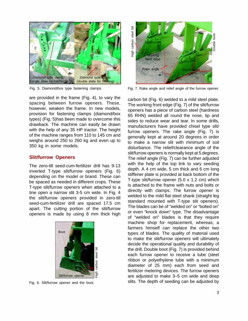
are provided in the frame (Fig. 4), to vary thespacing between furrow openers. These,however, weaken the frame. In new models,provision for fastening clamps (diamond/boxtypes) (Fig. 5)has been made to overcome thisdrawback. The machine can easily be drawnwith the help of any 35 HP tractor. The heightof the machine ranges from 110 to 145 cm andweighs around 250 to 260 kg and even up to350 kg in some models.
Slit/furrow Openers
The zero-till seed-cum-fertilizer drill has 9-13inverted T-type slit/furrow openers (Fig. 6)depending on the model or brand. These canbe spaced as needed in different crops. TheseT-type slit/furrow openers when attached to atine open a narrow slit 3-5 cm wide. In Fig. 4the slit/furrow openers provided in zero-tillseed-cum-fertilizer drill are spaced 17.5 cmapart. The cutting portion of the slit/furrowopeners is made by using 8 mm thick high
carbon bit (Fig. 6) welded to a mild steel plate.The working front edge (Fig. 7) of the slit/furrowopeners has a piece of carbon steel (hardness65 RHN) welded all round the nose, tip andsides to reduce wear and tear. In some drills,manufacturers have provided chisel type slit/furrow openers. The rake angle (Fig. 7) isgenerally kept at around 20 degrees in orderto make a narrow slit with minimum of soildisturbance. The relief/clearance angle of theslit/furrow openers is normally kept at 5 degrees.The relief angle (Fig. 7) can be further adjustedwith the help of the top link to vary seedingdepth. A 4 cm wide, 5 cm thick and 6 cm longstiffener plate is provided at back bottom of theT-type slit/furrow opener (5.0 x 1.2 cm) whichis attached to the frame with nuts and bolts ordirectly with clamps. The furrow opener iswelded to the mild flat steel shank (straight legstandard mounted with T-type slit openers).The blades can be of “welded on” or “bolted on”or even “knock down” type. The disadvantageof “welded on” blades is that they requiremachine shop for replacement, whereas, afarmers himself can replace the other twotypes of blades. The quality of material usedto make the slit/furrow openers will ultimatelydecide the operational quality and durability ofthe drill. Double boot (Fig. 7) is provided behindeach furrow opener to receive a tube (steelribbon or polyethylene tube with a minimumdiameter of 25 mm) each from seed andfertilizer metering devices. The furrow openersare adjusted to make 3–5 cm wide and deepslits. The depth of seeding can be adjusted by
Fig. 7. Rake angle and relief angle of the furrow opener.
Relief angleRake angle
Workingfront edge
Fig. 6. Slit/furrow opener and the boot.
Slit/furrow opener
Boot
Diamond type clamp,(single plate for hitching)
Diamond type clamp,(double plate for hitching)
Fig. 5. Diamond/box type fastening clamps
Dou
ble
boot
Hig
h ca
rbon
ste
el b
it
Hig
h ca
rbon
ste
el b
it

4
raising or lowering the depth-control sidewheels. However, depth of seeding can also beadjusted (independent of the depth-control sidewheels) by raising or lowering the shanks ofthe furrow openers. The depth control can alsobe effected with three point hitch hydraulics, inaddition to the depth-control wheels. The toplink is used to level the seeder. The unleveledmachine may otherwise lead to variable seedingdepth in different rows. The machine can beproperly leveled by a three-point linkage. Sincethe side link hydraulics often get damaged orbecome non-functional in most tractors withthe farmers, it is advisable to use the depth-control wheels or the top link.
Seed and Fertilizer Boxes
Trapezoidal shaped seed and fertilizer boxes,made of mild steel sheet (2 mm thick), aremounted side by side on the frame, fertilizerbox (Fig 8b) in front and seed box (Fig. 8a) inthe rear. The boxes are generally 145 cm longand 28 cm deep sufficient to hold 50 kg DAPand 50 kg wheat seed at one time, respectively.Box dimensions can vary but these generallydepend upon the effective width of the machineand will increase with the increase in thenumber of the slit/furrow openers. For examplein case of 11-tine drill, the length of seed andfertilizer boxes will be around 178 cm.
Fig. 9. Seed metering device and its components.
6. Seed boot
3. Aluminium cup
4. Plastic tube
5. Flow controlaluminium/plastic
tongue
2. Flutted rollers
1. Seed adjustment lever
1. Seed adjustment lever
2. Flutted rollers
3. Aluminium cup
4. Plastic tube
5. Flow control tongue
6. Seed boot
Fig. 8. Inner view of (a) Seed, and (b) Fertilizer boxes.
Seed Metering Device
Seed metering device has the followingcomponents (Fig. 9):
(a) (b)

5
viii. Collect the total seed under the seed-drilland measure its weight. Thus seed rate perhectare can be calculated. Any change inthe seed rate, if required, can beaccomplished by adjusting the lever andrecalibrating the machine till the desiredseed rate is obtained.
ix. Weigh the quantity of seed dropped fromeach opener and record on the data sheetto know the variation in different rows, ifany.
Example , say
n Circumferance of the drive wheel = 0.4 m
n Width of machine = 1.85 m
n As we know area of one hectare=10,000 m2
n Then distance/length (L) to cover onehectare will be =(10,000/1.85)=5405.4 m
n The distance (l) i.e. 1/100 of hectare will be= 54.5 m
n To cover distance (l), the drive wheel hasto take turns (n) = 54.5/0.4=136.25
n Allowing 10% slippage, the distance (l) canbe covered in ‘N’ turns (n–0.1n) = 123(approx.).
Put seed and fertilizer in the boxes. Set therate control adjustment lever as prescribed bythe manufacturer. Rest of the procedure will besimilar as described above at items vii-ix.
Calibration of seed-drill (in situ)
Select the recommended spacing (row to rowspacing) and seed rate for the specific varietyof crop to be sown.
Draw a line (dotted line as shown in Fig.10) passing through the recommended spacingon line A, seed rate on line B and extend itfurther to join the line C of the nomograph. Thispoint of intersection on line C will give thedesired seed quantity to be dropped per meterlength per row.
Flutted rollers made of aluminium facilitatecontinuous seeding of crops where control ofplant to plant distance is not needed (wheat,rice, toria etc.). Tooth size, depth of groove andthe number of flutes depend on the seed size.For example, there are 10 flutes in each rollerfor wheat seed. The rollers are fitted in a serieson a shaft. Aluminium cups are fitted on theserollers. Below the flutted rollers are aluminiumor plastic tongues to hold the seed. The tonguescan be raised or lowered depending on the sizeand texture (in case of rice) of the seed. As theflutted rollers turn, they push the seed over theedge of the seed cups attached at the bottomof seed metering box which funnels the seedthrough the plastic seed tubes to the slit/furrowopener. In funnel shaped boot, a deflector plateis provided for separation of seeds and fertilizer.A very precise seed rate adjustment is obtainedby sliding the flutted roller in or out. The moreis the exposed area of the flutted roller, thehigher will be the seed rate and vice-versa.
Calibration of seed-drill (in laboratory)
i. Measure the diameter (D) of the drivewheel and calculate its circumference i.e.πD in meters.
ii. Measure the effective width of coverage(W) in meters of the drilling machine bymultiplying number of furrows with spacing.
iii. Then distance/length (L) to cover onehectare is calculated by dividing 10000 m2
(area of one hectare) by effective coverage(W).
iv. The distance (l) i.e. l/100th of a hectare willbe equal to L/100 in meters.
v. To cover distance l, the drive wheel has totake ‘n’ turns i.e. = l/πD
vi. Allowing 10% slippage, the distance can becovered in ‘N’ turns i.e. = (n–0.1 n)
vii. Raise the seed drill so that drive wheelbecomes free to be turned. Put a chalkmark on the rim of the wheel. Fill the seedbox, set the seed rate adjusting lever androtate the wheel for ‘N’ turns.

6
Draw a straight line (dotted line as shown inFig. 10) joining 17.5 cm on line A and 40 kg/acre on line B and extend it further to intersecton line C at seed rate 1.8 g/meter length/row.So, the amount of seed for 10 meter length runper row = 1.8 x 10 = 18.0 g. Therefore, thefarmer should collect 18.0 g seed in each tubefor 10 meter run of the machine in the field. Ifthe quantity of seed collected is low/high, thenhe should adjust it with the metering lever. Ifwe know the seed test weight (weight/1000seeds) we can calculate the number of seeds/meter row length using the intersected value(e.g. 1.8 g, Fig. 10) as follows.
No. of seeds/meter row length (x) = 1000/seedtest weight × 1.8 g.
Since the farmers do not have weighingmachines, it is advisable to calibrate with seednumber/m row length. For this it is better tocalibrate number of seeds with the number ofrevolutions of the drive wheel. If thecircumference of the drive wheel is one m, thenthe lenth covered in 1 turn is also one meter.and x number of seed will fall.
Fertilizer Metering Device
The fertilizers metering device (Fig. 11) has thefollowing components:
1. Bottom of the fertilizer box with diamondshape holes
2. Scale
3. Fertilizer setting lever
4. Aluminium cup
5. Agitators
6. Flutted roller
7. Diamond shape holes
8. Fertilizer metering shaft (sometimes coatedwith plastic to avoid rusting)
The fertilizer metering device generally usedin drills is of hole mesh type (gravity-cum-forced feed type) arranged on a shaft.Sometimes it is called an agitator type fertilizer
Validation of the seed-drill calibration
Fill the seed box with seed and set the indicatorat desired seed rate according to the chartgiven by the manufacturer. Mark a distance of10 to 20 meters in the field. Run the seed drilland collect the seeds in each tube for 10 to 20meter length run.
The amount of seed collected in each tubein 10 or 20 meter run is then expressed in g/meter. This quantity should be equal to thecalculated seed quantity obtained from thenomograph in g/meter length/row. If themeasured quantity is less or more, adjust therate with the help of seed metering lever.Sliding the roller out will increase seed rate.Now, the seed drill is ready for planting thespecific seed.
Example:Supposition: Seed rate planned = 40 kg/acre
Spacing row to row = 17.5 cmPlant to plant spacing = continuous
Fig. 10. Nomograph for seed-drill calibration.

7
metering device. In the bottom of the fertilizerbox, diamond shape holes are made. Thequantity of fertilizer is adjusted by adjusting thesize of these holes. Star shaped agitators areprovided to avoid the bridging of fertilizer andto feed fertilizer continuously through the holes.The fertilizer setting handle/lever with scale isprovided to adjust the required quantity offertilizer. The fertilizer passes through the hole,into a funnel, to deliver fertilizer into the slit/furrow opener boots.
In other machines, fertilizer box deliversthe material to a cup fitted with rotating cells(Fig. 12). The rotating cells pick up the fertilizer
granules (small or large) and deliver them tothe fertilizer tubes. This mechanism has theadvantage of handling small or large sizedfertilizer granules such as urea supergranules(USG) and place them at desired soil depth.Deep placement of USG in rice culture isknown to improve efficiency by 20%. Also thereis no free flow of fertilizers on turnings of thetractor at field corners.
The rotating cell type fertilizer meteringdevice has the following components (Fig. 12):
1. Fertilizer tank
2. Shaft
3. Rollers
4. Cells/cups
5. Funnel
6. Leveling screw
Fig. 12. Rotating cup/cell type fertilizer meter
Fertilizer tank
ShaftRollerCell/Cup
Funnel
Levelingscrew
In cell type fertilizer metering device, cellsare fitted in separate compartments to allowfertilizer placement as required in each row orsome select rows only. Fertilizer can beincreased or decreased by lifting or lowering
Fig.11. Fertilizer metering device and its components.
8. Fertilizer metering shaft
7. Diamondshape holes
5. Agitators
6. Flutted roller
3. Fertilizersetting lever
2. Scale1. Bottom ofthe fertilizerbox withdiamondshape holes
4. Aluminiumcup

8
the fertilizer tank. respectively or by changingthe sprocket wheel.
Fertilizer is simply metered by a series ofcups on a roller. However, calibration of machinefor setting required rate of fertilizer underlaboratory situation as well as in situ can beaccomplished with similar procedure mentionedearlier under the headings “Calibration of seed-drill (in laboratory)” and “Calibration of seed-drill (in situ)”.
Power Transmission Unit
Power transmission unit (Fig. 13) has thefollowing main components:
1. Drive wheel
2. Shaft
3. Idler
4. Sprocket
5. Roller chain
or drive wheel is attached to the frame in front.Traction can be adjusted through a groove andspring as desired. Attachment of drive wheelin the front side of the frame sometimescreates problem in the free movement of wheeldue to soil or stubble blockage or due to itslocation being very near to the hook of thetractor. So now this wheel is being attached onthe rear side of the machine in new models(Fig. 14). A motorcycle roller chain of 12.50mm pitch with 14 and 37 number of teeth onthe mild steel sprocket is provided for powertransmission from the drive wheel to seed andfertilizer metering devices. Power from groundwheel is transmitted to a shaft (1:1) (Fig. 13)mounted on front frame. From this shaft poweris transmitted to seed and fertilizer meteringshafts (2.5:1) through the chain sprocketarrangement. However, size of roller chain andsprocket can vary in different models as perrequirements. An idler has been provided totighten or loosen the chain for its smoothrunning.
Depth-control Side Wheels
Two wheels (one on either side of the drill),each of 40 cm diameter (Fig. 15a) made of mildsteel sheet (closed type) or in some modelsmade of rubber, are provided to set the requiredseeding depth. The size of these wheels mayvary in different models. With the help of depthadjusting screws (Fig. 15b), these wheels canbe raised or lowered to increase or decreasethe depth of seeding, respecitvely. The depth
The power required to operate the seedand fertilizer metering devices is provided bya floating type lugged drive wheel 40 cm indiameter and 10.5 cm in width through chainand sprockets. However, size of the drivewheel may vary in different models. Fourteenlugs each of 3 cm height at an angle of 900 areprovided on the ground wheel to avoid slippage.Wheels are of iron closed type or with rubberon them for better traction. This ground wheel
Fig. 13. Power transmission unit and its main components.
(2) Shaft
(5) Rollerchain
(4) Sprocket
(1) Drivewheel
Lugs
(3) Idler
Fig. 14. Drive wheel attached on the rear side.
Clamps Drive wheel

9
Hitch points
Fig. 16. Hitch points.
One person can either stand or sit on thisplatform while the machine is in operation justto keep a watch that the seed and fertilizer arerunning properly through the respective plastictubes without any blockage. This is just aprecautionary measure and not a requirementper se. It may be mentioned that this practiceenables the sitting person to remove the rakedresidues as well. Therefore, it is advisable ifthis practice is followed.
Fig 15. Depth-control side wheel (a) and depth-adjustingscrew (b).
(b) Depth-adjusting screw
(a) Depth-control side wheel
of seeding in case of wheat varies from 3–5cm. However it can be adjusted as perrequirement.
If there is a large amount of loose straw inthe field, these depth wheels can get jammedwith the straw. If this happens, the depth-control wheels can be removed and depthcontrol maintained with the tractors’ hydraulics,to reduce straw jamming.
Hitch PointsThe drill has three standard hitch points; twolower and one upper (Fig. 16). The machine isattached to tractor through these three hitchpoints with the help of link pins. The top linkhitch point also helps in leveling the machines
Iron/wooden Platform or StandAn iron/wooden stand or platform is alsoattached to the rear side of the frame (Fig. 17).
Fig. 17. Iron/wooden platform attached to the rear sideof the frame.
Iron/wooden platform
Precautions for Use
n Sowing of wheat with zero-till seed-cum-fertilizer drill is best accomplished whensoils have 3-4% more moisture than underconventional method. Germination of wheatand other crops is adversely affected if thesoil is too dry.

10
Fig.18. Pre-germinated P. minor before sowing underzero-tillage.
n Conversely, zero-till machine does not workwell in fields where moisture levels are toohigh (wheel slippage) and under suchsituations care must be taken to preventblockage of seed and fertilizer tubes.
n Earlier sowing of wheat (last week ofOctober to 15 November) is possible underzero tillage and yields are generally higheras compared to late sowing of wheat. Thisis due to less infestation of weeds (e.g. P.minor) and more efficient nutrients-waterinteractions.
n Heat stress at grain filling is less in latewinter season when temperature begins torise. The overall growth period of crop ismore in early sowing.
n Longer duration varieties such as PBW343, HD 2687 having better vigour at earlygrowth and profuse tillering cover the soilsurface and are more competitive withweeds. Select cultivars with bettercompeting attributes.
n There is no need of planking before or afterplanting crops with zero-till drill
n When weed pressure is not a factor, tillingof soil is not needed and reduced tillage (1–2 plowings) and cross-sowing methods donot provide any additional advantage overzero tillage. Rather these methods mayreduce germination and yield and inducegermination of P. minor besides increasingthe cost of cultivation.
n Germination and emergence of wheat isnot adversely affected even if rains occurjust after sowing of wheat because crustformation does not take place under zerotillage. However, crop planted with zero tillin reduced tilled plots may bury seed deeperand may adversely affect crop stand.
n Germination of P. minor is reduced by 30–40%, if soil disturbance is reduced to theminimum as in the case with the zerotillage. P. minor seed generally fail togerminate if seed depth is > 5 cm.
n Herbicides like Round up/Glycel(glyphosate) @ 0.5% (5 ml/l of water) orGramaxone (paraquat) @ 0.3% (3 ml/l) in100 1 spray volume/acre are helpful incontrolling pre-germinated populations ofP. minor (Fig. 18). This avoids use ofpreparatory tillage. Post-emergenceherbicides such as clodinafop @ 60 g/ha(Topik @ 160 g/acre), fenoxaprop @ 120g/ha (Puma Super @ 480 g/acre) orsulfosulfuron @ 25 g/ha (Leader @ 13.5g/acre) have been successful in controllingweeds (P. minor) after germination of wheat.In case annual weeds are present at thetime of seeding, Gramaxone (paraquat) @0.3% (3 ml/l of water) may be used but inthe presence of perennial weeds Roundup or Glycel @ 1.0% solution should bepreferred. However, herbicides should beapplied at a proper time and inrecommended dose with knapsack sprayerfitted with flat fan nozzle tips. It is advocatedthat use of post-emergence herbicidesmust be rotated each year to reduce thecapacity of weeds to develop resistance.Spray should be accomplished at 2 to 3leaf stage of P. minor.
n It has been observed that farmer can skipthe use of herbicides when zero tillage andalternate herbicides are carefully integratedfor 3–4 years.
n Irrigation immediately after sowing of wheatis not recommended. If needed, post-sowing

11
irrigation may be given a week ahead ofconventionally practiced irrigation schedule.
n Possibilities of emergence of broadleafweeds in place of P. minor under long-termzero-till fields are well expected. However,it will be comparatively easy and cheap tocontrol broadleaf weeds in wheat usingherbicides like 2,4-D or metsulfuron. Basedon long-term permanent trials since 1997/98, it has been observed that there is nosignificant shift in weed flora till date.
n Encouraging results of wheat sown withzero-till machine have also been realizedunder saline, and alkali soils.
n Zero-till sowing of wheat is possible instanding stubbles of paddy (after harvest)without burning (Fig. 20), which not onlyadds residue in the soil to increase andimprove its quality but also preventsenvironmental pollution. If loose straw ofpaddy is lying on the soil surface, it shouldbe collected aside before seeding to avoidinterruption in the seeding operation anduniformly broadcast it after seeding to serveas mulch.
n There is no need to change use ofnitrogenous and phosphatic fertilizers ratein zero tillage. Keep application rates thesame as followed under conventionalmethod of planting.
Fig. 19. Sowing of wheat with zero-till seed-cum-fertilizerdrill in standing stubbles of paddy without burning.
III. Zero-Till Drill-cum-BedPlanterZero-till drill-cum-bed planter (Fig. 20) is aprototype which has been developed bycombing a zero-till seed-cum-fertilizer drill witha bed planter. Efforts have been made toincorporate the functions of these two separatemachines in one combined unit. It can be usedto harness the benefits of both zero-till seed-cum-fertilizer drill as well as of a bed planterand guidelines and instructions for its useshould be followed accordingly.
Major Components and theirDescription
Zero-till drill-cum-bed planter has the followingmajor components (Fig. 20):
1. Frame
2. Slit/furrow opener
3. Ridger and bed-cum-furrow shaper
4. Seed box and fertilizer boxes
5. Seed metering device
6. Fertilizer metering device
7. Power transmission unit:
(a) Driving wheel and (b) Sprocket
8. Hitch points
9. Iron/wooden platform or stand
10. Depth-control side wheels
11. Interculture tines
Frame
The frame of zero-till drill-cum-bed planter (Fig.20) has a size of 215 x 80 cm and it is madefrom mild steel channel section of size 75 x 40mm. Unlike simple zero-till machine, zero till-drill-cum-bed planter has a 3 bars frame forattachment of replaceable parts such as depth-control wheel, shovels, tines and shaper. Twochannel sections placed one above another(three in number at 1800) at a spacing of 1.5

12
cm are welded with a side plate of the size 100× 5 mm. Clearance of holes 1.5 cm is providedfor fitting shank of furrow openers to the framewith the help of U-clamp bolts. New model hasbox type pipe frame for improved frame strength.
Furrow Point Openers
In the combined unit, the machine has chiseltype 9-13 furrow openers, 17.5 cm apart.However, the space between furrow openerscan be adjusted as per requirement. Thecutting portion of chisel type point openerwhich makes a very narrow slit is made byusing 8 mm thick mild steel plate with a workingfront of hard steel (Fig. 21). The working frontedge of furrow opener is coated with electrodeof carbon steel to reduce wear and tear. Therake angle (Fig. 22) has been kept at 20degrees in order to make a narrow slit withoutcausing much soil disturbance. The relief angle(Fig. 22) of the furrow openers has been keptat 5 degrees. The furrow opener is welded tomild flat steel shank (5.0 × 1.2 cm) which isattached to the frame with nut and bolts or
directly with clamps. The “bolted on” bladescan be replaced by farmers whereas “weldedon” blades will require machine shops to replacethem. The “weld on” openers are replaced with“knock out” type openers which are easy toreplace. Double boot is provided behind eachfurrow opener to receive a tube each from seedand fertilizer metering devices. These furrowopeners make 3–5 cm wide and deep slit. Thedepth of seeding can be adjusted by raising orlowering the depth-control side wheels. It canalso be adjusted (independent of the depth-control side wheels) by raising or lowering theshanks of the furrow openers. The machinecan be properly leveled by three-point linkage.
Ridger and Bed-cum-furrow Shaper
Ridger and bed-cum-furrow shaper (Fig. 20b)have been combined together and mounted atthe front bar of the frame. The length of the
Baseframe
Furrowopener
Shaper
Ridger-cum-shaper for bed planter
Seed box andFertilizer box
Fertilizermeteringdevice
Seedmeteringdevice
Drive wheel
Chainand
sprocket
Hitch point
Depthsettingwheel
Fig. 20. Zero-till drill-cum-bed planter and its majorcomponents.
(a)
(b)
Cha
nnel
s fo
r fr
ame
Removablecentralridger
Fig. 21. Furrow openers of the zero-till drill-cum-bedplanter.
Fig. 22. Rake angle and relief angle of the furrow opener.
Boot
Depthsettingwheel
Furrowopener
Workingfront edge
Rake angle
Relief angle

13
bed-cum-furrow shaper is 200 cm, while thewidth of the bed-maker is 36 cm. Double endshovels (Fig. 23) (three in number) of 7 cmwidth at a distance of 60 cm have beenprovided with bed-cum-furrow shaper to openthe furrow. Triangular furrows with 30 cm topwidth and depth each are made with thisshaper. However, the bed width and furrowdepth are adjustable. If the central shovel isremoved (Fig. 20b) it is possible to have widerbeds of one meter width which are good fornursery raising or crops requiring wider spacing.Shaper or ridger (Fig. 24) can be detachedwhen this machine is to be used as zero-tillseed-cum-fertilizer drill. Whereas the shapershould be attached in front of the openers withthe machine when it is to be used as a bedplanter. Additionally, when it is in use as a bedplanter, furrow openers should also be adjusted
by removing or raising few furrow openers withshanks according to the number of rows andspacing in different crops to be raised on thetop of the raised beds.
In some machines ridger and shaper/packing rollers have been provided separately.Three ridgers (Fig. 20b) have been provided tomake two beds in a single pass. But most ofthe farmers have tractors in the range of 35-45 HP and 3 ridgers can easily be pulled bythese tractors. Height of the beds in wheatvaries from 15 to 30 cm and it can be furtheradjusted. Whereas the width of furrow and topof the bed generally remain 30 cm and 37 cm,respectively. However, it can be varied from 20to 40 cm by adjusting the wing width (Figs. 23,25).
Seed and Fertilizer Boxes
The seed and fertilizer boxes (Fig. 26) of thedrill are made up of mild steel sheet (2 mmthick). The seed box is on the rear side and thefertilizer box is towards the front side. However,
Fig. 23. Ridger, bed-cum-furrow shaper fitted with doubleend shovel
Wings ofridger
Fig. 25. Wings of ridger
Provision forWing widthadjustment
Adjustable wings
Packing rollers
Fig. 24. Ridger of the zero till drill-cum-bed former.
Ridger
Double endShovels
Adjustable/removable
wings
14
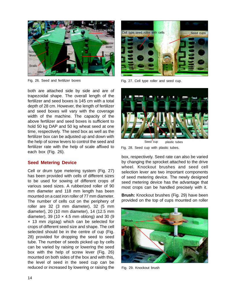
both are attached side by side and are oftrapezoidal shape. The overall length of thefertilizer and seed boxes is 145 cm with a totaldepth of 28 cm. However, the length of fertilizerand seed boxes will vary with the coveragewidth of the machine. The capacity of theabove fertilizer and seed boxes is sufficient tohold 50 kg DAP and 50 kg wheat seed at onetime, respectively. The seed box as well as thefertilizer box can be adjusted up and down withthe help of screw levers to control the seed andfertilizer rate with the help of scale affixed toeach box (Fig. 26).
Seed Metering Device
Cell or drum type metering system (Fig. 27)has been provided with cells of different sizesto be used for sowing of different crops ofvarious seed sizes. A rubberized roller of 90mm diameter and 118 mm length has beenmounted on a cast iron roller of 77 mm diameter.The number of cells cut on the periphery ofroller are 32 (3 mm diameter), 32 (5 mmdiameter), 20 (10 mm diameter), 14 (12.5 mmdiameter), 39 (10 × 4.5 mm oblong) and 30 (9× 13 mm zigzag) which can be selected forcrops of different seed size and shape. The cellselected should be in the centre of cup (Fig.28) provided for dropping the seed to seedtube. The number of seeds picked up by cellscan be varied by raising or lowering the seedbox with the help of screw lever (Fig. 26)mounted on both sides of the box and with this,the level of seed in the seed cup can bereduced or increased by lowering or raising the
box, respectively. Seed rate can also be variedby changing the sprocket attached to the drivewheel. Knockout brushes and seed cellselection lever are two important componentsof seed metering device. The newly designedseed metering device has the advantage thatmost crops can be handled precisely with it.
Brush: Knockout brushes (Fig. 29) have beenprovided on the top of cups mounted on roller
Fig. 26. Seed and fertilizer boxes
Fig. 29. Knockout brush
Cell type seed roller with cells Seed cups
Fig. 27. Cell type roller and seed cup.
Fig. 28. Seed cup with plastic tubes.
Seed cup plastic tubes
Fertilizer boxSeedbox
Screwlever
Scale
Idler
Screwlever
Scale
Brush

15
just to remove extra seeds sticking with eachother.
Seed cell selection lever: Seed cell selectionlever (Fig. 30) has been provided to move theroller and the desired cell according to seedsize and shape which can be selected beforeseeding.
Power Transmission Unit
Power transmission unit and its componentshave been sown in Fig. 32. Power from luggedground wheel/drive wheel (Fig. 33) can betransmitted to a shaft (1:1 and 1:1.5 or vice-versa) mounted on the frame. From this shaft,power is transmitted to seed and fertilizermetering shafts through chain and sprocket(Fig. 34) arrangement in the ratio of 3:1, 2.25:1,2:1, 1.5:1 to the fertilizer shaft, whereas to theseed metering shaft in the ratio of 1:1, 1.5:1and 2:1. An idler sprocket (Fig. 35) has beenprovided to tighten or loosen the chain for itssmooth running.
Fig. 30. Seed cell selection lever
Cell plate/rollers
Screw lever
Scale
Fertilizer Box
Fig. 31. Fertilizer metering device and its components.
Fertilizer Metering Device
The cell type fertilizer metering device has fourseparate compartments made up of mild steelsheet and in each compartment three cellplates/rollers (Fig. 31) are provided at thebottom of fertilizer box. The quantity of thefertilizer is varied by maintaining the level offertilizer in the cell plate compartments whichis regulated by raising or lowering the fertilizerbox with the help of screw lever (Fig. 31)provided at both sides of the fertilizer box.Further improvement has been made in themetering device to use urea as such or in theform of granules/pellets.
Drive wheel
Chain
Sprocket
Idler
Shaftmountedon frame
Fig. 32. Power transmission unit and its components.
Fig. 33. Drive wheel
Seedcellselectionlever
Brushes
Drive wheel
Lugs Variable speedsprocket wheel
16
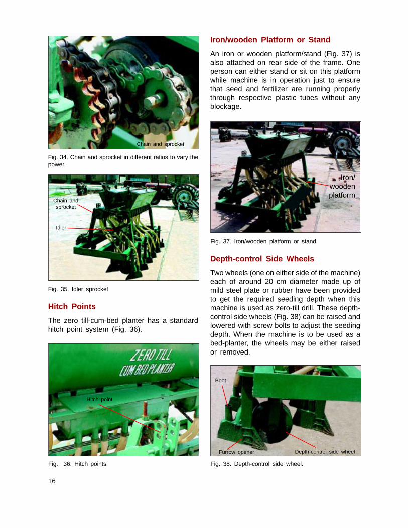
Fig. 36. Hitch points.
Iron/wooden Platform or Stand
An iron or wooden platform/stand (Fig. 37) isalso attached on rear side of the frame. Oneperson can either stand or sit on this platformwhile machine is in operation just to ensurethat seed and fertilizer are running properlythrough respective plastic tubes without anyblockage.
Fig. 38. Depth-control side wheel.
Fig. 34. Chain and sprocket in different ratios to vary thepower.
Fig. 35. Idler sprocket
Hitch Points
The zero till-cum-bed planter has a standardhitch point system (Fig. 36).
Fig. 37. Iron/wooden platform or stand
Depth-control Side Wheels
Two wheels (one on either side of the machine)each of around 20 cm diameter made up ofmild steel plate or rubber have been providedto get the required seeding depth when thismachine is used as zero-till drill. These depth-control side wheels (Fig. 38) can be raised andlowered with screw bolts to adjust the seedingdepth. When the machine is to be used as abed-planter, the wheels may be either raisedor removed.
Chain and sprocket
Chain andsprocket
Idler
Hitch point
Depth-control side wheelFurrow opener
Boot
Iron/woodenplatform

17
Interculture Tines
Interculture tines (Fig. 39) with boots havebeen provided which can be fitted on frame asand when there is need for mechanical weedingand urea application/topdressing between tworows of a crop and on both sides of the raisedbed. At the time of mechanical weeding, furrowopeners used for seeding and furrow-cum-bedshaper/packing rollers are removed. But ridgersremain attached, which can be adjusted inwardif needed (to keep outer rows from damage),during mechanical weeding to control weedsparticularly in furrows.
Precautions for Use
In addition to the ‘Precautions for use’ given inthe section relating to zero-till seed-cm-fertilizerdrill, the following precautions may also thekept in mind for using the bed planter.
n Field should be leveled and well preparedbefore making beds.
n Beds are made well in advance and fieldirrigated to encourage germination of weedsbefore sowing and then germinated weedscan be controlled either mechanically byreshaping the beds or during sowingoperation or with the spray of non-selectiveherbicide glyphosate (Round up/Glycel,41% SL) @ 1.0% solution before sowing.As such, resistant Phalaris minor (kanki/mandusi) in rice-wheat cropping sequenceand broad leaf weeds in sandy or sandyloam soils with other crop rotations caneasily be controlled.
Fig. 39. Interculture tines
n Do not allow drying up of the upper soillayer before sowing otherwise seed willhave to be placed deep and it will affectgermination.
n Mechanical weeding or interculture withthis machine (after making minor alterationsin the position of its tines) is possible in thestanding crop, if it has been sown in tworows/bed. There can be intercultivation justin the furrows, in case of 3 rows/bed.
n Special care should be taken regardingdepth of seeding; otherwise there may beproblems in germination.
n Attack of termites may be another problemin sandy areas; hence, special attention orprecaution should also be taken in thisregard.
n Sometimes due to imbalance of machineattached with tractor or present shape ofwings of ridger, soil layer on one side topof alternate beds is formed which mayhamper seed germination. So care shouldbe taken by the farmers to balance themachine to remove this soil layer or tomodify the wings by getting these cut atouter edges.
IV. Tips for Manufacturers,Operation, Maintenance andRepair
For Manufacturers
n Machine should be of good quality andmanufactured according to appropriatedesign specifications/drawing.
n Frame shanks and furrow openers shouldbe strong and made of proper material.
n Provision should be made for replaceableparts on wear and tear.
n There should be stress-free and properalignment of components without any inbuiltstress assembly.
Interculture tines

18
n Testing before marketing should be ensuredat manufacturer level.
n Spare parts, critical components, nuts andbolts or clamps should be of high strengthand standard quality.
n Minimum tool kit should be provided.
n Packing, handling and transportation shouldbe proper.
n Pooled service should be provided free ofcost for replacement of parts or completemachine, if there is any defect or breakageduring transportation.
n Manufacturer should incorporate requiredmodification based on feed back from timeto time.
Planting Operations
Following points must be kept in mind beforeactual planting operation:
n Seed should be of good quality and freefrom dirt and dust.
n Fertilizer should not have clods. Clodsshould be properly broken to uniform sizefor free flow of fertilizer.
n All the nuts and bolts, rollers and springsshould be thoroughly checked, defectiveparts should be replaced and nuts/boltsproperly tightened.
n Seed and fertilizer boxes, flutted rollers,fertilizer metering shaft and controllingbottom plate (having triangular holes) shouldbe thoroughly cleaned.
n Flutted roller shaft should move freely,otherwise the rollers may be broken.
n Feed cups should be thoroughly cleanedand obstruction if any, must be removed.
n Ensure that plastic pipes do not haveexcessive bend. This will block the freeflow of seed and fertilizer in tubes.
n Chain sprocket of metering mechanismshould be properly aligned. Appropriatetension in the chain may be kept for freemovements of seed and fertilizer metering
shafts. If there is any noise during operation,stop the machine and check it.
n Furrow openers should be fitted on theframe according to the requirement (row torow distance) of the crop. There should beno crossing or twisting of furrow openers.
n Fill the seed and fertilizer boxes andcalibrates the machine. Ensure that seeddrill is set at desired seed and fertilizerrates. This will ensure proper metering ofseed and fertilizers and result in excellentgermination, good crop stand and higheryield.
Maintenance and Repair
A well maintained and properly adjusted seedingmachine gives trouble free service for a longtime. It also helps in timely completion ofoperations The following important points maybe kept in mind for the maintenance and repairof various components of the seeding machines.
A. Seed and Fertilizer Boxes
The boxes should be thoroughly cleaned asthese may rust very fast due to environmentalmoisture. This will damage the boxes andmachine will not be useful for the next cropsowing season. The boxes must be cleaned asunder:
n Raise the machine above ground so thatthe drive wheels move freely
n Remove seed and fertilizer from boxes.
n Open the flow gates of seed and fertilizercups.
n Rotate the drive wheel till the seed andfertilizer from different seed and fertilizercups are emptied. Clean the boxes andcups with the help of a cloth or brush.
n Wash the machine rollers/seed/fertilizerboxes with diesel to avoid rusting.
n Apply lubricating oil at appropriate places(bushes and sides of metering rollers).

19
B. Drive/power Transmission System
For maintenance of drive system/powertransmission system, keep following points inmind:-
n Drive wheel should move freely. If it isjammed, then apply grease or put oil in itsbushes. If axle of wheel is bent or worn out,replace it.
n Drive wheel should be round, if it is bentthen repair it.
n Sprockets of drive wheel and feed shafts(seed and fertilizer boxes) should beproperly aligned.
n All sprockets should be properly tightenedon their shafts so that these may not movefreely on these shafts.
n Feed shafts should move freely. If theseare jammed due to rusting,, then clean andapply lubricating oil/grease in the bushes.
n Bent drive shafts should be repaired orreplaced.
n Seed and fertilizer boxes should bethoroughly cleaned for free movement offeed shafts.
n Chain and idler sprocket should be properlytightened so that proper chain tension ismaintained and mechanism moves freely.
n Worn out parts, loose, broken and worn outbushes should be replaced.
C. Seed Metering Mechanism
Usually flutted roller type seed meteringmechanism is used in these seeding machine.It should be repaired and maintained as under.
n Side plate of seed metering shaft sprocketshould be removed by loosening nuts/bolts.
n Remove the nuts/bolts of all the seed cups.
n Remove pins of all the flutted rollers.
n Remove metering rollers from the seed
cups and replace broken rollers and notchedplates.
n Take out the shaft on one side. All rollerswill come out of seed cups.
n During refitting of rollers, it must be ensuredthat all the rollers are at equal distance inthe seed cups. If distance is different, thenput varcels (washers) to achieve equaldistance.
n Put the rollers on the shaft and put againon the seed box.
n Complete system should move freely androtate the sprocket till appropriate seedrate is achieved from all the rollers.
D. Fertilizer Metering Mechanism
In fertilizer metering mechanism, fertilizer settleson its parts due to environmental moisturewhich may cause obstruction in free and uniformflow of fertilizer. Large particles also causehindrance in the mechanism. In some of theseeding machines, adjustable triangular holeswith agitator are provided for fertilizer metering.Therefore, this system requires special attentionas follows:
n After seeding a crop, fertilizer should beremoved from the box and whole systemshould be cleaned with the help of brushor cloth.
n If the system is jammed due to corrosionand rusting, the lower plate having triangularholes must be removed and cleaned withkerosene or diesel.
n All the holes in the box should be properlyopen.
n Agitators provided on the shaft should alsobe cleaned and the lubricating oil/greasemay be applied in the bushes of the fertilizermetering shaft.
n Lever for adjustment of fertilizer rates shouldmove freely.
n Tighten all nuts and bolts of the mechanism.

20
Likewise in other seeding machines whichpossess rotating cup type metering deviceshould also be cleaned carefully. Eachcompartments, cup/cell and funnel should befree from jamming and the roller should movefreely.
E. Seed and Fertilizer Tubes
These are mostly plastic tubes connected toseed/fertilizer cups and their lower ends areconnected to seed boots.
n Tubes should be connected to seed/fertilizercups with the help of clamps so that thesemay not come out during field operation.
n Tubes should be protected from bendingand breakage.
n Old/bent tubes should be replaced.
n Excessive bend in the tubes should beavoided otherwise the bend will causeobstruction in free flow of seed/fertilizerand results in non-uniform application offertilizer in the field.
F. Furrow Openers
Furrow openers are attached to main framewith the help of nuts/bolts. The furrow openerswear out or twist very fast. Therefore, theseshould be repaired frequently. The worn-outones should be removed/replaced as and whenrequired.
G. General
n All the components of the machine shouldbe painted
n Machine should be protected from rain, dirtand dust etc. during its storage.
n Moving parts should be greased/oiled atregular intervals so that the machine givesa trouble free service for a long time.
n Users training will lead to improvement inthe performance of the machines.
Annexure I
List of Manufacturers
1. A.S.S. Foundary and Agricultural Wroks, JandialaGuru, Amritsar, Punjab
2. National Agro Industries, Ludhiana, Punjab
3. Kamla Engineering Works, Ismailabad,Kurukshetra, Haryana
4. Laxmi Agriculture Engineering Works, Kaithal
5. Ashoka Farming and Engineering Works, ShabadMarkanda, Kurukshetra, Haryana
6. Narwal Engineering Works, Shabad Markanda,Kurukshetra, Haryana
7. Viswa Karma Engineering Works, Tohana,Fatehabad, Haryana
8. Guru Nanak Krishi Udyog, Pehowa, Kurukshetra,Haryana
9. Guru Nanak Khalsa Engineering Works, Pehowa,Kurukshetra, Haryana
10. Kadian Engineering Works, Kaitahal, Haryana
11. Malwa Agriculture Engineering Works, Tohata,Fetehabad, Haryana
12. M/s Jhandu Engineering Works, Ambala, Haryana
13. Guru Nanak Foundry and Engineering Works,Kaithal, Haryana
14. Super Agricultural Industries, Karnal, Haryana
15. Beri Krishi Udyog, Karnal, Haryana
16. Darshan Singh Agri. Works, Karnal, Haryana
17. Pyara Singh Agri. Works, Karnal, Haryana
18. Bharat Agricultural Industries, Karnal, Haryana
19. Sarswati Krishi Udyog, Karnal, Haryana
20. Punni Agricultural Engineering Works, Fatehabad,Haryana
21. Sukhvindra Agricultural Works, Talwandi, Punjab
22. Panishar Agricultural Works, Amargarh, Punjab
23. Malwa Agro Industries, Ludhiana, Punjab
24. Doaba Agricultural Works, Sitarganj, U.S. Nagar,Uttaranchal
25. Tyagi Agro Industries, Kitcha, U.S. Nagar,Uttranchal
26. Hans Engineering Works, Suraj Kund Road,Phool Bagh Colony, Meerut, U.P.

Publications of the Rice-Wheat Consortiumfor the Indo-Gangetic Plains
I. Paper Series1. Long-term Soil Fertility Experiments in Rice-Wheat Cropping Systems: Proceedings of a Workshop edited
by I P Abrol, K F Bronson, J M Duxbury and R K Gupta. 1997.
2. Reduced and Zero Tillage Options for the Establishment of Wheat after Rice in South Asia by Peter R.Hobbs, Ghana Shyam Giri and Peter Grace. 1997.
3. Herbicide Resistance - a Major Issue for Sustaining Wheat Productivity in Rice-Wheat Cropping Systemsin the Indo-Gangetic Plains edited by R K Malik, G Gill and P R Hobbs. 1998.
4. Nematode Pests in Rice-Wheat-Legume Cropping Systems – Proceedings of a Regional Training Courseedited by S B Sharma, C Johansen and S K Midha. 1998.
5. Sustaining Rice-Wheat Production Systems : Socio-economic and Policy Issues edited by Prabhu L Pingali.1999.
6. Long-term Soil Fertility Experiments in Rice-Wheat Cropping Systems edited by I P Abrol, K F Bronson,J M Duxbury and R K Gupta. 2000.
7. Nematode Pests in Rice-Wheat-Legume Cropping Systems : Proceedings of Review and Planning Meeting andTraining Workshop by S B Sharma, Pankaj, S Pande and C Johansen. 2000.
8. Stagnation in the Productivity of Wheat in the Indo-Gangetic Plains : Zero-till-seed-cum-fertilizer Drill as anIntegrated Solution by R S Mehla, J K Verma, R K Gupta and P R Hobbs. 2000.
9. Soil and Crop Management Practices for Enhanced Productivity of the Rice-Wheat Cropping System in theSichuan Province of China edited by P R Hobbs and R K Gupta. 2000.
10. Potential Yields of Rice-Wheat System in the Indo-Gangetic Plains of India by P K Aggarwal, K K Talukdarand R K Mall. 2000.
11. Rice-Wheat Cropping Systems of the Indo-Gangetic Plain of India by R S Narang and S M Virmani. 2001.
12. Rice-Wheat Cropping System of Nepal by S P Pandey, S Pande, C Johansen and S M Virmani. 2001.
13. Baseline Study on Agricultural Mechanization Needs in Nepal by Madan P Pariyar, Khadga B. Shrestha andNara Hari Dhakal. 2001.
II. Traveling Seminar Report Series1. Research and Extension Issues for Farm-Level Impact on the Productivity of the Rice-Wheat Systems in the
Indo-Gangetic Plains of India and Pakistan edited by R K Gupta, P R Hobbs, M Salim, R K Malik, M R Varma,T P Pokharel, T C Thakur and J Tripathi. 2000.
2. Study of Research and Extension Issues in the Sichuan Province of China for Farm-Level Impact on theProductivity of the Rice-Wheat System edited by R K Gupta, P R Hobbs, M Salim, N H Chowdhary andS I Bhuiyan. 2000.
3. Design Improvements in Existing Zero-till Machines for Residue Conditions by Raj K Gupta and Joseph Rickman.2002.
4. Options for Establishment of Rice and Issues Constraining its Productivity and Sustainability in Eastern GangeticPlains of Bihar, Nepal and Bangladesh by R K Gupta, A K Shukla, M Ashraf, Z U Ahmed, R K P Sinha andP R Hobbs. 2002
III. Technical Bulletin Series1. RWC-PRISM User Manual for Data Entry & Updating and Focal Point Management. 2001
2. Herbicide Application Using a Knapsack Sprayer by Andrew Miller and Robin Bellinder. 2001
3. ihB ij yVdk;s tkus okys Lizs iEi ls 'kkdukf'k;ksa dk iz;ksx] ys[kd % , feYyj] vkj csfyUMj] vkj ds efyd]v'kksd ;kno ,oa ,y-,l cjkM+] 2002
4. Manual for Using Zero-Till Seed-cum-Fertilizer Drill and Zero-Till Drill-cum-Bed Planter by A. Yadav, R K Malik,N K Bansal, Raj K Gupta, Samar Singh and P R Hobbs. 2002

Rice-Wheat Consortiumfor the Indo-Gangetic Plains
!
!
!
!
!
The Consortium is an Ecoregional Program of the Consultative Group onInternational Agricultural Research (CGIAR), managed by CIMMYT, involving theNational Agricultural Research Systems, the International Agricultural ResearchCenters, and the Advanced Research Institutions. Its main objective is to promoteresearch on issues that are fundamental to enhance the productivity andsustainability of rice-wheat cropping systems in South Asia.
These objectives are achieved through:
Setting priorities for focused research on problems affecting many farmers.Promoting linkages among rice-wheat research specialists and other branches ofresearch and extension.Encouraging interdisciplinary team approach to understand field problems and tofind solutions.Fostering quality work and excellence among scientists.Enhancing the transfer of improved technologies to farmers through establishedinstitutional linkages.
Financial support for the Consortium's research agenda currently comes from manysources, including the Governments of Australia, Netherlands, Sweden, Switzerland,and the Department for International Development (DFID), the International Fund forAgricultural Development (IFAD), the United States Agency for InternationalDevelopment (USAID), and the World Bank.
Facilitation UnitRice-Wheat Consortium for the Indo-Gangetic Plains
CG Block, National Agriculture Science Centre (NASC) Complex,DPS Marg, Pusa Campus, New Delhi 110 012, India
ISSN: 0972-2084
Telephone + 91 (11) 5822940, 5827432 Fax + 91 (11) 5822938E-mail: [email protected]
Visit our World Wide Web site at http://www.rwc.cgiar.org
![[R. K. Bansal]Strength of Materials 4th Ed[Engineersdaily.com]](https://static.fdocuments.net/doc/165x107/563db804550346aa9a8fc482/r-k-bansalstrength-of-materials-4th-edengineersdailycom-568b8a1fcda22.jpg)

![[R. k. bansal]strength of materials 4th](https://static.fdocuments.net/doc/165x107/55c5d089bb61eb8b798b4602/r-k-bansalstrength-of-materials-4th-55c63a74a3297.jpg)
![[R. k. bansal] Strength of materials 4th](https://static.fdocuments.net/doc/165x107/55b6d3d4bb61eb93418b48d0/r-k-bansal-strength-of-materials-4th.jpg)


![[R. k. bansal]strength of materials 4th ed[engineersday.com]](https://static.fdocuments.net/doc/165x107/5888c1071a28ab200f8b5515/r-k-bansalstrength-of-materials-4th-edengineersdaycom-5911d996ccde2.jpg)
![[R. K. Bansal]Strength of Materials 4th Ed[56Engineersdaily.com]](https://static.fdocuments.net/doc/165x107/55cf854b550346484b8c701b/r-k-bansalstrength-of-materials-4th-ed56engineersdailycom.jpg)


