Information, Application, Checklist Building & Fire Safety ...

ManualFIRE SAFETYfor existing RMG buildings
October 2014
2|47
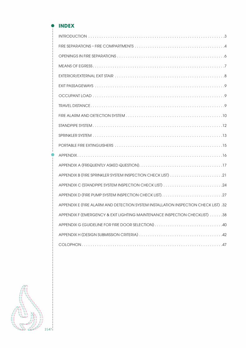
INDEX
INTRODUCTION . . . . . . . . . . . . . . . . . . . . . . . . . . . . . . . . . . . . . . . . . . . . . . . . . . . . . . . . . . . . . .3
FIRE SEPARATIONS – FIRE COMPARTMENTS . . . . . . . . . . . . . . . . . . . . . . . . . . . . . . . . . . . . . . . . .4
OPENINGS IN FIRE SEPARATIONS . . . . . . . . . . . . . . . . . . . . . . . . . . . . . . . . . . . . . . . . . . . . . . . . .6
MEANS OF EGRESS . . . . . . . . . . . . . . . . . . . . . . . . . . . . . . . . . . . . . . . . . . . . . . . . . . . . . . . . . . . .7
EXTERIOR/EXTERNAL EXIT STAIR . . . . . . . . . . . . . . . . . . . . . . . . . . . . . . . . . . . . . . . . . . . . . . . . . .8
EXIT PASSAGEWAYS . . . . . . . . . . . . . . . . . . . . . . . . . . . . . . . . . . . . . . . . . . . . . . . . . . . . . . . . . . .9
OCCUPANT LOAD . . . . . . . . . . . . . . . . . . . . . . . . . . . . . . . . . . . . . . . . . . . . . . . . . . . . . . . . . . . .9
TRAVEL DISTANCE . . . . . . . . . . . . . . . . . . . . . . . . . . . . . . . . . . . . . . . . . . . . . . . . . . . . . . . . . . . . .9
FIRE ALARM AND DETECTION SYSTEM . . . . . . . . . . . . . . . . . . . . . . . . . . . . . . . . . . . . . . . . . . . .10
STANDPIPE SYSTEM . . . . . . . . . . . . . . . . . . . . . . . . . . . . . . . . . . . . . . . . . . . . . . . . . . . . . . . . . . .12
SPRINKLER SYSTEM . . . . . . . . . . . . . . . . . . . . . . . . . . . . . . . . . . . . . . . . . . . . . . . . . . . . . . . . . . .13
PORTABLE FIRE EXTINGUISHERS . . . . . . . . . . . . . . . . . . . . . . . . . . . . . . . . . . . . . . . . . . . . . . . . .15
APPENDIX . . . . . . . . . . . . . . . . . . . . . . . . . . . . . . . . . . . . . . . . . . . . . . . . . . . . . . . . . . . . . . . . . .16
APPENDIX A (FREQUENTLY ASKED QUESTION) . . . . . . . . . . . . . . . . . . . . . . . . . . . . . . . . . . . . . .17
APPENDIX B (FIRE SPRINKLER SYSTEM INSPECTION CHECK LIST) . . . . . . . . . . . . . . . . . . . . . . . .21
APPENDIX C (STANDPIPE SYSTEM INSPECTION CHECK LIST) . . . . . . . . . . . . . . . . . . . . . . . . . . .24
APPENDIX D (FIRE PUMP SYSTEM INSPECTION CHECK LIST) . . . . . . . . . . . . . . . . . . . . . . . . . . . .27
APPENDIX E (FIRE ALARM AND DETECTION SYSTEM INSTALLATION INSPECTION CHECK LIST) .32
APPENDIX F (EMERGENCY & EXIT LIGHTING MAINTENANCE INSPECTION CHECKLIST) . . . . . .38
APPENDIX G (GUIDELINE FOR FIRE DOOR SELECTION) . . . . . . . . . . . . . . . . . . . . . . . . . . . . . . .40
APPENDIX H (DESIGN SUBMISSION CRITERIA) . . . . . . . . . . . . . . . . . . . . . . . . . . . . . . . . . . . . . .42
COLOPHON . . . . . . . . . . . . . . . . . . . . . . . . . . . . . . . . . . . . . . . . . . . . . . . . . . . . . . . . . . . . . . . .47
3|47
INTRODUCTION
This manual is developed by the Accord on Fire and Building Safety to support factories in the implementation of fire protection measures.
Fire protection is a fundamental Accord goal. The Accord is primarily concerned with the life safety aspects of fire protection. The keys to fire life safety are:
• fire prevention
• early warning of the fire
• containment of the fire
• safe exits.
This manual addresses all of these aspects except fire prevention which is addressed in a separate document. This manual also deals only with existing buildings. The Accord has some different requirements for new construction, as there are different options available for achieving safety in a newly constructed building.
Early warning of fire is achieved through automatic fire alarm systems. Automatic fire alarm systems are required in all garment factories. Fire alarms can be initiated automatically by smoke detectors or heat detectors, or manually by pull stations. The alarm then sounds by means of bells or horns in order to notify the occupants to evacuate the building.
Containing the fire is achieved by creating fire compartments using fire resistant walls and floors. Fire barriers are required from floor to floor in multi-storey buildings, around certain rooms within the building, and to enclose exit stairwells. Sprinkler systems serve two functions: detecting the fire for immediate evacuation; and containing the fire at its source.
Safe and efficient exiting is accomplished by providing necessary exits (at least two), and ensuring that the exits remain free of smoke and fire by requiring fire barriers around the exit stairs. Locks are not permitted on exits.
4|47
FIRE SEPARATIONS – FIRE COMPARTMENTS
Fire separations are provided within buildings to limit the spread of fire. Certain rooms, areas, and occupancies in buildings are generally fire separated into fire compartments. These fire compartments limit fire spread for a specified period of time intended to allow persons to escape and to limit fire growth until the fire department extinguishes the fire.
Consider a fire compartment to be a box. Most buildings have many fire compartments (boxes), which are situated side by side and on top of each other. Each fire compartment has walls, a floor and a ceiling. The walls are fire separations that limit the spread of fire horizontally from one fire compartment to an adjoining fire compartment. The top and bottom of each fire compartment are often referred to as floor assemblies when they separate one storey from another. The floor assemblies are fire separations that limit the spread of fire vertically from one fire compartment to another.
Fire separations can be constructed of combustible or non-combustible elements or a combination of materials. For example, masonry walls and reinforced concrete floor slab assemblies are considered to be non-combustible. Due to the physical characteristics of the materials, they have substantial strength and will effectively limit the spread of fire provided the assembly has been properly constructed and maintained.
The design and types of material used in the construction of a fire separation will determine its fire-resistance rating. The fire-resistance rating of a fire separation means the time in hours or fractions thereof that a material or assembly of materials will withstand the passage of flame and transmission of heat when exposed to fire under specified conditions of test and performance criteria.
The design of the fire separation, the thickness and qualities of materials used and the manner of construction will determine the fire-resistance rating for the entire assembly.
The fire resistance ratings of structural elements, building components or assemblies shall be determined in accordance with the test procedures outlined in ASTM E 119 or UL 263.
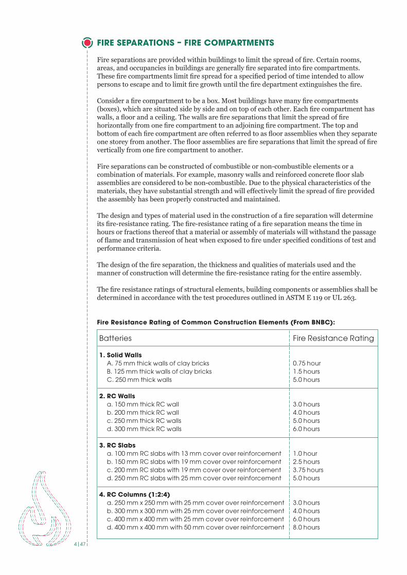
Fire Resistance Rating of Common Construction Elements (From BNBC):
Batteries Fire Resistance Rating
1. Solid Walls A . 75 mm thick walls of clay bricks 0 .75 hour B . 125 mm thick walls of clay bricks 1 .5 hours C . 250 mm thick walls 5 .0 hours
2. RC Walls a . 150 mm thick RC wall 3 .0 hours b . 200 mm thick RC wall 4 .0 hours c . 250 mm thick RC walls 5 .0 hours d . 300 mm thick RC walls 6 .0 hours
3. RC Slabs a . 100 mm RC slabs with 13 mm cover over reinforcement 1 .0 hour b . 150 mm RC slabs with 19 mm cover over reinforcement 2 .5 hours c . 200 mm RC slabs with 19 mm cover over reinforcement 3 .75 hours d . 250 mm RC slabs with 25 mm cover over reinforcement 5 .0 hours
4. RC Columns (1:2:4) a . 250 mm x 250 mm with 25 mm cover over reinforcement 3 .0 hours b . 300 mm x 300 mm with 25 mm cover over reinforcement 4 .0 hours c . 400 mm x 400 mm with 25 mm cover over reinforcement 6 .0 hours d . 400 mm x 400 mm with 50 mm cover over reinforcement 8 .0 hours

5|47
Floor assemblies and roof assemblies that have a required fi re-resistance rating are structurally supported by walls, columns or arches that have been designed and constructed with the same fi re-resistance rating as the assembly they support. This practice prevents premature collapse of the structure under fi re conditions resulting from the supporting elements located below having a lower fi re-resistance rating.
It is important to note that the fi re-resistance rating of an assembly is based upon all of the components of the assembly. The individual elements in themselves do not have a fi re- resistance rating.
Fire separations must be constructed as a continuous element to act as a barrier against the spread of fi re. A fi re separation is required to be continuous and extend from one fi re separation to another or to an exterior wall or roof. Appropriate fi re stopping is also essential to retard the passage of smoke and fl ame, particularly at locations where a vertical fi re separation meets a fl oor or roof assembly.
For example, where a vertical fi re separation that abuts a horizontal fi re separation involving a T-Bar ceiling assembly, the wall must extend through the concealed ceiling space and terminate so that a smoke-tight joint is provided at the fl oor slab above.
Plumbing, wiring and mechanical services commonly pass through required fi re separations. The penetrations in the fi re separations should be examined to determine if fi re stopping has been provided at the penetrations. These penetrations are often poorly sealed or neglected. Ducts and ventilation openings that pass through a required fi re separation must have a fi re damper installed at these penetrations. The fi re damper is required in order to maintain the integrity of the fi re separation.
Special note: Openings and penetrations into and through an exit enclosure are prohibited with the exception of required exit doors, sprinkler piping, standpipes, electrical raceway for fi re alarm equipment, and electrical conduit serving the exit enclosure only.
Shafts that are provided in a building to facilitate the installation of building services such as mechanical, electrical and plumbing installations and facilities including elevators and chutes must be enclosed by fi re separations.
Some rooms or spaces require special consideration. These spaces are required to be enclosed by fi re separations having a specifi ed fi re-resistance rating. The enclosure confi nes the fi re to the area of fi re origin. Areas requiring special attention include: • Exit Stairs, elevator shafts and other vertical shafts – 1 hour fi re rating if building is less than 4 stories, – 2 hour fi re rating if building is 4 stories or greater• Storage rooms – 1 hour fi re rating, • Boiler or furnace rooms – 1 hour fi re rating, • Generator rooms – 2 hour fi re rating, • Oil fi lled transformer rooms – 2 hour fi re rating unless in a high rise building – 4 hour fi re rating if in a high rise building
Example:
1 2
Picture 1 No proper
separation between working fl oor and
fabric store has been provided .
Picture 2 Boiler has been
installed near production fl oor
without proper separation .
6|47
OPENINGS IN FIRE SEPARATIONS
Openings in fi re separations are required to be protected with closures to limit the spread of smoke and fi re through the opening from one fi re compartment to another. A closure means a device or assembly for closing an opening through a fi re separation. Examples of closures are a door, a shutter, wired glass or glass block. All components, such as hardware, closing devices, frames and anchors are included in the rated assembly.
Closures can consist of a variety of materials. The closures can be permanently mounted in the fi re separation and be fi xed shut (i.e. wired glass window, glass blocks, etc.) or they may be capable of being opened or closed when necessary (i.e., door, shutter, damper, etc.).
When closed, closures limit the spread of fi re by virtue of their physical construction. Closures in fi re separations are required to have a specifi ed fi re rating. Closures and frames usually have a permanent label attached to them identifying their listed fi re rating.
REQUIRED RATINGS OF CLOSURES IN FIRE SEPARATIONS: • 1.5-hour fi re rated closure in a 2-hour fi re separation, • 1-hour fi re rated closure in a 1-hour fi re rated exit enclosure,• 0.75-hour fi re rated closure in a 1-hour fi re separation other than exit enclosure. • Fire windows shall conform to NFPA 257 or British, European, Chinese, or Indian standard
for fi re window tests. The ASTM standard referenced in the BNBC Part 4 Section 1.5.5 has been withdrawn.
• Fire door assemblies shall conform to NFPA 252, BS 476 Part 22, EN 1634-1, GB 12955-2008, or IS 3614 Part II. The ASTM standard referenced in the BNBC Part 4 Section 1.5.4 has been withdrawn.
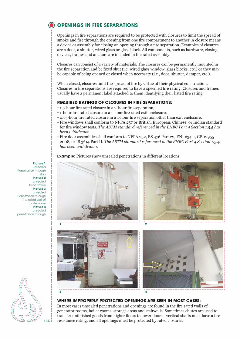
Example: Pictures show unsealed penetrations in diff erent locations
WHERE IMPROPERLY PROTECTED OPENINGS ARE SEEN IN MOST CASES:In most cases unsealed penetrations and openings are found in the fi re rated walls of generator rooms, boiler rooms, storage areas and stairwells. Sometimes chutes are used to transfer unfi nished goods from higher fl oors to lower fl oors– vertical shafts must have a fi re resistance rating, and all openings must be protected by rated closures.
1
3
2
4
Picture 1 Unsealed
Penetration through slab
Picture 2 Unsealed
Penetration Picture 3 Unsealed
Penetration through the rated wall of
boiler roomPicture 4Unsealed
penetration through

7|47
Example:
Standard: Accord Standard Part-4 Section: 4 .5 .2 .3, 4 .5 .4, 4 .5 .5, 4 .5 .7 .3, 4 .6 and BNBC Part-4 Section: 2 .5 .
MEANS OF EGRESS
A means of egress is a continuous and unobstructed way of exit travel from any point in a building to a public way. A means of egress consists of three parts: exit access, exit, and exit discharge. Exit access is the path from any location within a building to an exit. An exit is typically a door leading to the outside or, in a multi-story building, an enclosed exit stairway. Exit discharge is the path from the exit to the public way. A public way is a space that is permanently deeded and dedicated to public use, most often a street or lane.
BASIC REQUIREMENTS FOR MEANS OF EGRESSFor any storey with only two exits, the maximum occupant load should not exceed 500 people.
For any storey with only three exits, the maximum occupant load should not exceed 1000 people.
For rooms with more than 49 occupants, doors must swing in the direction of egress (i.e. the doors must swing out of the room).
For areas with more than 49 occupants, doors should be equipped with panic hardware (crash bars).
In buildings without automatic sprinkler protection, exits must be separated by at least 1⁄2 the diagonal dimension of the room. In buildings equipped throughout with automatic sprinkler protection, exits in each room should be separated by at least 1/3 of the diagonal dimension of the room. In other words, if the room has two exits, but they are very close to each other, it only counts as one exit.For example, the diagonal dimension of a square, 50’ by 50’ room would be approximately 70 feet. In a sprinklered building, the exit doors in this room would have to be separated by at least 23 feet. In an unsprinklered building, the exit doors would have to be separated by at least 35 feet.
Exit doors should lead to an exit stair enclosure, or directly to the exterior of the building. Egress routes should not pass through adjacent rooms, and should not pass through hazardous areas (such as kitchens, storage rooms, loading docks, etc.). If there are questions regarding egress through adjacent areas, they should be brought to our attention for further evaluation.
Exit doors must not be equipped with locking hardware that would allow an occupant to be locked inside the room or space. Exit doors should also not be equipped with secondary locking devices, such as a deadbolt or slide bolt, etc. It should be possible to open any designated exit door using a single motion, without the use of a key, tool, or special knowledge.
1 2
Picture 1 Shows unprotected
opening of generator room to
the adjacent building or egress
path .
Picture 2 Shows non-rated glass partitioned
opening to the exit enclosure and non-rated wooden door
has been used .

8|47
Each occupant must be provided with at least 4mm of egress width for exit doors. For example, if the exit door is 32 inches wide, a maximum of 200 occupants could egress through that door. Stairs require 8mm per person. The rules for minimum number of exits still apply.
Occupant load is also limited by the size of the room, and depends on how the room is being used. (See occupant load below.)
Minimum widths:
Standard: Accord Standard Part 6 section 6 .5
EXTERIOR/EXTERNAL EXIT STAIR
Exterior exit stairs shall be separated from the building with the required ratings. If the exit stair connect three or fewer stories, the stair shall be separated from the building with 1-hr rated construction and if it connect four or more stories then shall be separated from the building with 2-hr rated construction.
The rating of the exterior wall shall extend 3.05 m (10 ft) beyond the ends of the stair structure.
Example:
Standard: Accord Standard Part 6 section 6 .5, 6 .6 and 6 .8
Structural Element Fire Resistance Rating
Exit doors (existing) 0 .8m (32 in .)
Exit doors (new) 1 m (40)
Aisles 0 .9m (36 in .)
Corridors 1 .1m (44 in .)
Stairs (existing) 0 .9m (36 in .)
Stairs (new) 1 .5m (59 in .)
Stair Landings (existing) 0 .9m (36 in .)
Ramps 1 .1m (44 in .)
Picture shows an external
stair with unprotected glass window of left and
right side .

9|47
EXIT PASSAGEWAYS
General: An exit passageway is an exit component that is separated from other interior spaces of a building or structure by fi re resistance-rated construction and opening protection, and provides for a protected path of egress in a horizontal direction to the exit discharge or the public way.
Use: Exit passageways shall be considered an extension of the stairs and shall not be used for any other purpose.
Construction Rating: Exit passageways shall have walls, ceilings, and fl oors that meet the same rating requirement as the exit that is being served and shall not be less than 1-hr fi re-resistance rated construction.
Termination: Exit passageways shall terminate at an exit discharge.
OCCUPANT LOAD
The occupant load, in number of persons for whom means of egress are required, shall be determined on the basis of the occupant load factors in BNBC Part4 Section 3.5.1 that are characteristic for the use of the space or the maximum probable population of the space, whichever is greater.
THE OCCUPANT LOAD FACTORS FROM THE BNBC ARE AS FOLLOWS:• RMG (G1 & G2) factories shall have a calculated occupant load of 2.3m2 per occupant
(25ft2 per occupant). This occupant load factor is permitted to be increased or decreased based on the actual number of occupants.
• Assembly (E) with tables and chairs: 1.5m2 per occupant (16ft2per occupant) net• Assembly without fi xed seats: 0.7m2per occupant (7ft2per occupant) net• Offi ces(F): 10m2per occupant (100ft2per occupant) gross• Other Industrial (G): 10m2per occupant (100ft2per occupant) gross• Storage (H): 30m2per occupant (300ft2per occupant) gross• Hazardous (J): 10m2per occupant (100ft2per occupant) gross
Standard: Accord Standard Part 6 section 6 .4
TRAVEL DISTANCE
The maximum travel distance to reach an exit from any point in the building shall not exceed 45 meters unless the following requirements can be met:
Picture shows travel
distance (A-F, B-E, C-F, D-E) from
diff erent locations .

10|47
Travel distance limitations for G2 (RMG factories) shall be increased to 60 m (200 ft) where a complete automatic fire detection system, portable fire extinguishers, and standpipe system are provided in accordance with this Standard.
Travel distance limitations for G2 (RMG factories) shall be increased to 122 m (400 ft) where a complete automatic sprinkler system, automatic fire alarm system, and portable fire extinguishers are provided in accordance with this Standard.
Standard: Accord Standard Part 6 Section 6 .13
FIRE ALARM AND DETECTION SYSTEM
All garment factories require an automatic fire alarm system that activates the alarm and occupant notification devices by manual or automatic initiating devices (e.g. smoke detector, heat detector, sprinkler water flow) in the event of fire.
When complete automatic sprinkler protection is provided throughout a floor with water flow devices designed to initiate the alarm notification, smoke and fire detection devices can be eliminated throughout that floor.
Basic components of a fire alarm system: the following is a list of the basic components that can be installed together to make up a typical fire alarm system:
Where Required: Automatic fire alarm and detection systems shall be installed throughout all new and existing garment factories.
Installation requirements: All installation and design requirements outlined in BNBC Part 4 Section 4.4 shall be supplemented by the requirements of NFPA 72.
Documentation: Installation of new fire alarm and detection systems shall be required to provide shop drawings as outlined in NFPA 72.
Documentation Review: All fire alarm installations shall be submitted to the Chief Safety Inspector for review prior to commencement of installation.
Alarm Initiation Devices
• Manual Fire Alarm Boxes • Water flow Initiating Devices Heat
Detectors • Smoke Detectors • Radiant Energy Sensing Fire Detectors • Other Fire Detectors
Fire Alarm Control Units • Conventional fire alarm systems • Addressable fire alarm systems • Annunciator panel
Cables • Minimum 2-core- 1.5 mm2 Fire resistant/FP200 cables for Detectors and Minimum
2-core- 2 .5mm2 FR/FP 200 Cables for NAC Circuit .
Notification Appliances • Bells • Horns • Speakers • Sirens • Strobes • Combination units
Batteries • Standby Power
11|47
Acceptance testing: Testing of the installation shall be conducted in accordance with NFPA 72 acceptance testing requirements. Documentation of all testing shall be submitted for review by the Chief Safety Inspector. A final inspection and testing of the installation shall be witnessed by the Chief Safety Inspector or designate.
Evacuation: Automatic alarm evacuation shall be provided upon initiation of any of the following: manual alarm box, water flow alarm, or two or more automatic smoke or fire detection devices. Notification shall be provided throughout the building for total evacuation. Existing partial evacuation systems shall be replaced.
Monitoring: Until that time that a central station monitoring service or direct connection to the Fire Service and Civil Defense can be set up, a person shall be assigned to contact the fire department in the event of fire alarm activation. An annunciator shall be located in a constantly attended location to alert this person.
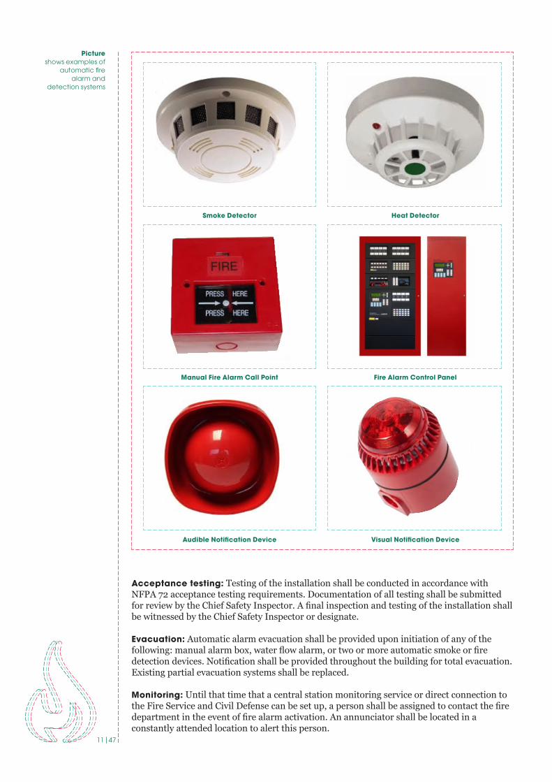
Picture shows examples of
automatic fire alarm and
detection systems
Smoke Detector
Manual Fire Alarm Call Point
Audible Notification Device
Heat Detector
Fire Alarm Control Panel
Visual Notification Device

12|47
STANDPIPE SYSTEM
A stand pipe consists of rigid water piping which is built into buildings in a vertical position to which fi re hoses can be connected, allowing manual application of water to the fi re. Within the context of a building, a standpipe serves the same purpose as a fi re hydrant.
Where Required: Standpipe systems shall be installed throughout all new and existing buildings and structures where the highest occupied fl oor is more than 10 m (33 ft) above grade or more than 10 m (33 ft) below grade.Location of hose connections:
• Class I standpipe hose connections (65 mm) shall be located in all required stairwells at each fl oor level including occupiable roofs.
• Class II standpipe hose connections (40 mm) shall not be required if the building is protected with automatic sprinklers.
Installation requirements: All installation and design requirements outlined in BNBC Part 4 Chapter 4 for combined standpipe and automatic sprinkler systems shall be replaced by the requirements of NFPA 14 with a minimum pressure of 450 kPa (65 psi) at the hydraulically most remote hose connection. Standalone standpipe systems shall meet the BNBC requirements with a minimum 450 kPa (65 psi) pressure at the hydraulically most remote hose connection, or NFPA 14.
Documentation: Installation of new combined standpipe and sprinkler systems shall be required to provide shop drawings and hydraulic calculations as outlined in NFPA 14. These drawings shall include all details as outlined in NFPA 14.
Documentation Review: All standpipe system installations shall be submitted for review to the Chief Safety Inspector prior to commencement of installation.
Acceptance testing: Testing of the installation shall be conducted in accordance with NFPA 14 acceptance testing requirements. Documentation of all testing shall be submitted for review by the Chief Safety Inspector. Final inspection and testing of the installation shall be witnessed by the Chief Safety Inspector or designate.
Fire department connections: Fire department (Siamese) inlet connections shall be provided to allow fi re department pumper equipment to supplement the fi re protection systems. Fire department outlet connections shall be provided to allow fi re department pumper vehicles to draw water from ground-level or underground water storage tanks. Connections shall match the Fire Service and Civil Defense hose thread standard.
1 2
Picture 1 shows 65mm
(Class I) standpipePicture 2
shows 40mm (Class II) standpipe
connectionPicture 3
shows 65mm inlet connections for Fire
Department .
3
13|47
SPRINKLER SYSTEM
A fi re sprinkler system is an active fi re protection measure, consisting of a water supply system, providing adequate pressure and fl ow rate to a water distribution piping system, onto which fi re sprinklers are connected.
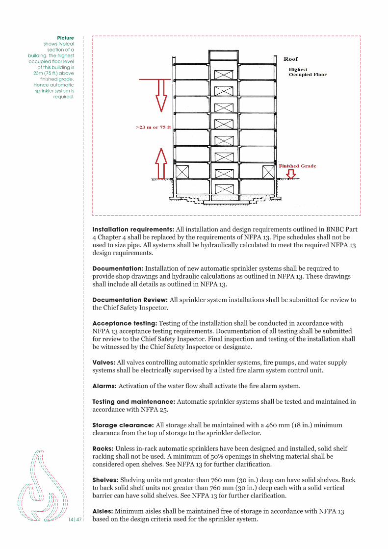
Where Required: Automatic sprinkler protection shall be installed throughout all portions of new and existing high-rise buildings with an occupiable fl oor greater than 23 m (75 ft) above the fi nished grade.
Existing buildings greater than 2 stories with nonrated construction shall not exceed 2000 m2 (22,000 sq. ft.) per fl oor unless automatic sprinkler protection is provided throughout.
Fire Pump: Fire pump design and installation shall be as per NFPA 20. The fi re pump capacity shall be determined by the hydraulic calculation. One duty pump and one standby pump shall be installed. Jockey pump can be installed to overcome pressure losses due to leakages. Pressure Relief Valve, Test valves, OS&Y Gate Valves, Non Return Valves and Alarm check Valves are some of the valves required with the pump assembly.
Piping: Minimum wall thickness of steel pipes shall be in accordance with NFPA 13.
Zone Control Valves shall be installed in every fl oor or zone. A zone control valve consists of i) Butterfl y Valve, ii) Flow Switch and iii) Test and Drain. The fl ow switch and Butterfl y valve shall be interfaced with Fire Alarm System.
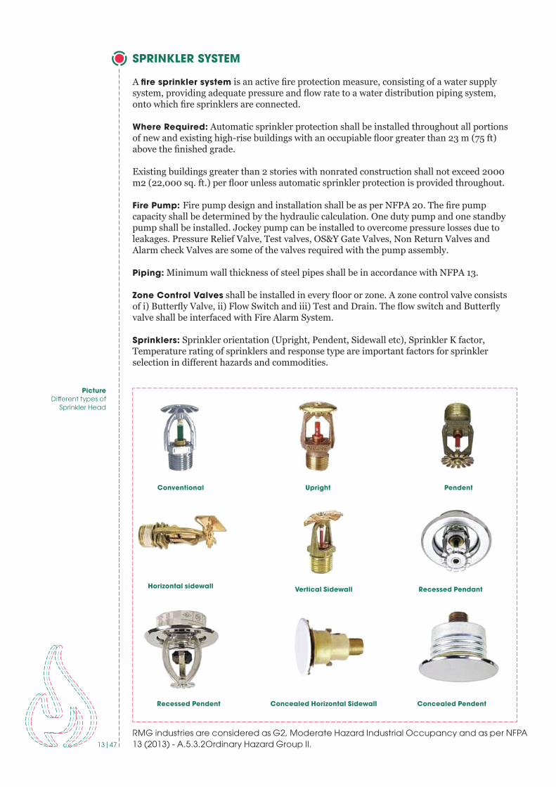
Sprinklers: Sprinkler orientation (Upright, Pendent, Sidewall etc), Sprinkler K factor, Temperature rating of sprinklers and response type are important factors for sprinkler selection in diff erent hazards and commodities.
Picture Diff erent types of
Sprinkler Head
RMG industries are considered as G2, Moderate Hazard Industrial Occupancy and as per NFPA 13 (2013) - A .5 .3 .2Ordinary Hazard Group II .
Concealed Horizontal SidewallRecessed Pendent Concealed Pendent
Horizontal sidewall Vertical Sidewall Recessed Pendant
Conventional Upright Pendent
14|47
Installation requirements: All installation and design requirements outlined in BNBC Part 4 Chapter 4 shall be replaced by the requirements of NFPA 13. Pipe schedules shall not be used to size pipe. All systems shall be hydraulically calculated to meet the required NFPA 13 design requirements.
Documentation: Installation of new automatic sprinkler systems shall be required to provide shop drawings and hydraulic calculations as outlined in NFPA 13. These drawings shall include all details as outlined in NFPA 13.
Documentation Review: All sprinkler system installations shall be submitted for review to the Chief Safety Inspector.
Acceptance testing: Testing of the installation shall be conducted in accordance with NFPA 13 acceptance testing requirements. Documentation of all testing shall be submitted for review to the Chief Safety Inspector. Final inspection and testing of the installation shall be witnessed by the Chief Safety Inspector or designate.
Valves: All valves controlling automatic sprinkler systems, fi re pumps, and water supply systems shall be electrically supervised by a listed fi re alarm system control unit.
Alarms: Activation of the water fl ow shall activate the fi re alarm system.
Testing and maintenance: Automatic sprinkler systems shall be tested and maintained in accordance with NFPA 25.
Storage clearance: All storage shall be maintained with a 460 mm (18 in.) minimum clearance from the top of storage to the sprinkler defl ector.
Racks: Unless in-rack automatic sprinklers have been designed and installed, solid shelf racking shall not be used. A minimum of 50% openings in shelving material shall be considered open shelves. See NFPA 13 for further clarifi cation.
Shelves: Shelving units not greater than 760 mm (30 in.) deep can have solid shelves. Back to back solid shelf units not greater than 760 mm (30 in.) deep each with a solid vertical barrier can have solid shelves. See NFPA 13 for further clarifi cation.
Aisles: Minimum aisles shall be maintained free of storage in accordance with NFPA 13 based on the design criteria used for the sprinkler system.
Picture shows typical
section of a building, the highest occupied fl oor level
of this building is 23m (75 ft .) above
fi nished grade. Hence automatic sprinkler system is
required .
15|47
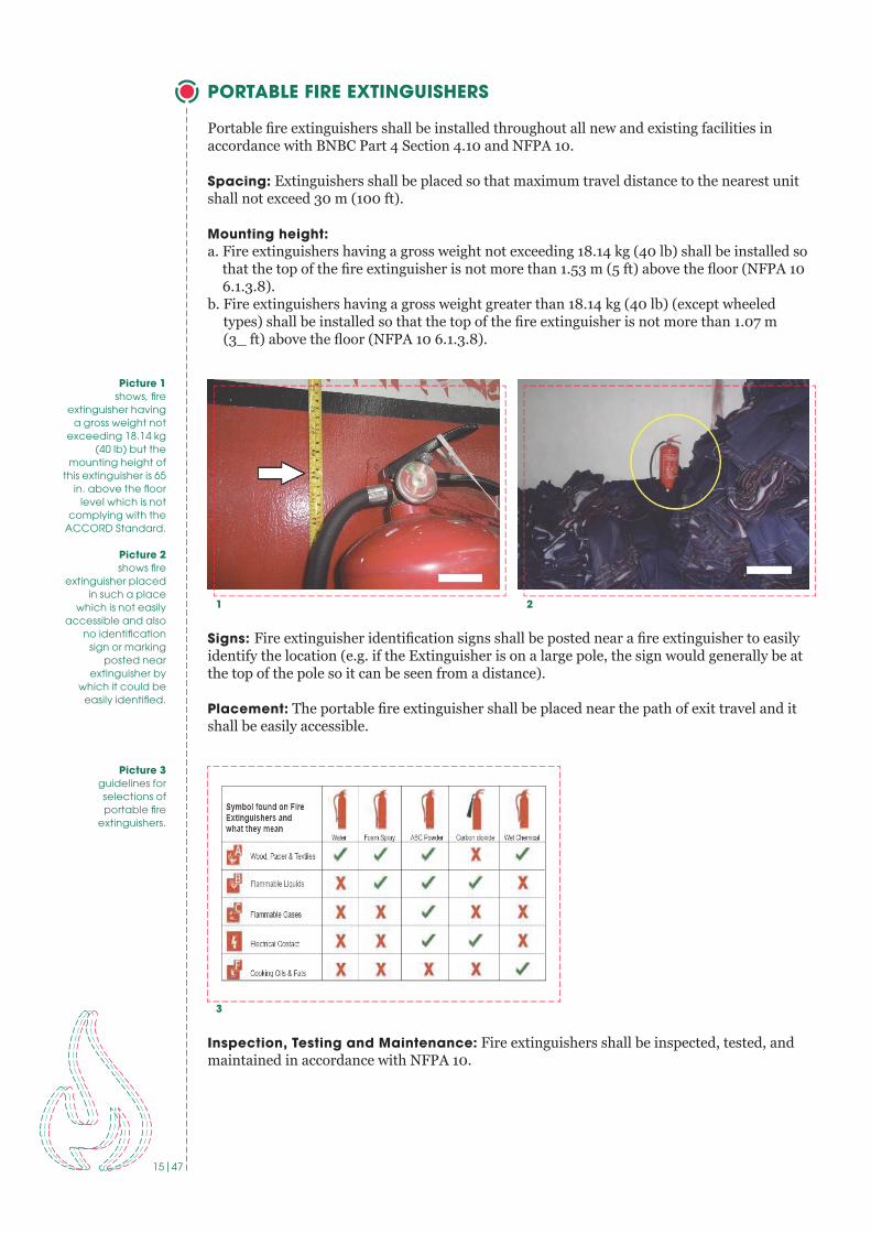
PORTABLE FIRE EXTINGUISHERS
Portable fi re extinguishers shall be installed throughout all new and existing facilities in accordance with BNBC Part 4 Section 4.10 and NFPA 10.
Spacing: Extinguishers shall be placed so that maximum travel distance to the nearest unit shall not exceed 30 m (100 ft).
Mounting height:a. Fire extinguishers having a gross weight not exceeding 18.14 kg (40 lb) shall be installed so
that the top of the fi re extinguisher is not more than 1.53 m (5 ft) above the fl oor (NFPA 10 6.1.3.8).
b. Fire extinguishers having a gross weight greater than 18.14 kg (40 lb) (except wheeled types) shall be installed so that the top of the fi re extinguisher is not more than 1.07 m (3_ ft) above the fl oor (NFPA 10 6.1.3.8).
Signs: Fire extinguisher identifi cation signs shall be posted near a fi re extinguisher to easily identify the location (e.g. if the Extinguisher is on a large pole, the sign would generally be at the top of the pole so it can be seen from a distance).
Placement: The portable fi re extinguisher shall be placed near the path of exit travel and it shall be easily accessible.
Inspection, Testing and Maintenance: Fire extinguishers shall be inspected, tested, and maintained in accordance with NFPA 10.
1 2
Picture 1 shows, fi re
extinguisher having a gross weight not
exceeding 18 .14 kg (40 lb) but the
mounting height of this extinguisher is 65
in . above the fl oor level which is not
complying with the ACCORD Standard .
Picture 2 shows fi re
extinguisher placed in such a place
which is not easily accessible and also
no identifi cation sign or marking
posted near extinguisher by
which it could be easily identifi ed.
Picture 3guidelines for selections of portable fi re
extinguishers .
3

16|47
APPENDIX

17|47
APPENDIX A (FREQUENTLY ASKED QUESTION)
1. Must fire exit doors be kept open?
Answer: No, fire doors are normally closed. Fire doors must be equipped with automatic closers and latches. If fire doors are required to beheld open for functional reasons, magnetic hold open devices may be provided. Magnetic hold open devices must release upon fire alarm. Wedges under the door or tying the door open are not permitted under any circumstances.
2. During factory operation the fire doors should be opened or closed?
Answer: Closed is preferred, but, if the factory wants to keep the door open, a magnetic hold open device maybe used which shall be interfaced with fire alarm system in such a way that in case of fire the door will be closed automatically getting the signal from Fire Alarm Panel. Wedges under the door or tying the door open are not permitted under any circumstances.
3. Are basket type ladders required to be installed?
Answer:No. Sufficient protected exit stairways are required in all factory buildings.
4. Is there any specific reference on the fire door approval authority? What are the credible organizations that can supply certified fire doors as per Accord requirements?
Answer:1. Doors shall be tested by a UL, FM or other recognized third party complying with the
standards mentioned in Accord standard- NFPA 252; BS 476 part 22, EN 1364-1, GB 12955-2008 etc. The standard shall be mentioned in the certificate provided by the testing laboratory and the door must be manufactured in accordance with the certification agency terms.
2. The fire doors and frames shall have permanent labeling with the information of themanufacturer, model number, the listing agency and the rating.
3. If the doors contain glass, it must be tested and have the same fire rating of the door.4. The test certificate shall mention the testing of the door with glass inserts if applicable.5. The door hardware will also be listed as fire rated or tested as part of the assembly.
A third party certification does the following:1. Tests the fire door to the approved standard.2. Helps to ensure the durability and reliability of the product.3. Verifies the manufacturing facility, audits the quality control procedures and the
manufacturer’s ability to produce the product as tested.4. Provides a marking procedure used to identify the product in the field.[Reference: Accord Standard Part 4, Section 4.5.4]
5. If the width of an exit opening is large (aprx. 8 to 9 feet) then what measures need to be taken? How are fire doors installed for those exits?
Answer: Two or three fire rated doors may be needed in this circumstance. Installation procedure shall follow the manufacturer’s recommendations.
6. Is a sprinkler system required to be installed on all floors of a high rise building?
Answer:Yes. If the floor level of the highest occupiablefloor is equal to or greater than 23 meters (75 feet) then a sprinkler system is required throughout the building as per NFPA13.
[Reference: Accord Standard Part 5, Section 5.3]
18|47
7. Do all of the exit doors need to have panic hardware (push bars)?
Answer:Yes. All fire doors to be push bar type as per the Accord standard where the floor or room contains more than 50 occupants.[Reference: Accord Standard Part 4, Section 4.5.4]
8. Are Alliance Building, Fire and Electrical safety reports accepted by the ACCORD?
Answer: The Accord requires independent inspections carried out under the direction of the Accord Chief Safety Inspector. However, the Accord has developed a policy allowing the Chief Safety Inspector to accept Alliance inspections in most circumstances.
9. Are electrical distribution panel boards/boxes acceptable at the exit doors?
Answer: They are not acceptable in exit stairwell enclosures.
10. If the boiler is located outside of the factory building, is a fire resistive wall required?
Answer:Any room or space housing boilers or other heat producing equipment shall be separated from other spaces by a minimum 1 hour construction or by a minimum spatial separation of 3 m (10 ft) where located exterior to the building.[Reference: Accord Standard Part 3, Section 3.4.2.1.2; BNBC Table 3.2.2]
11. Do electrical rooms requirea fire resistive door and wall?
Answer:Yes, for electrical rooms the wall should be of minimum 2 hour fire rated construction. A 1.5 hour fire rated door is required.
12. Do fire doors need to be installed at the roof level?
Answer: Usually not, but a swing type door is required, and if the roof is occupied then it may need to be a fire door.[Reference: Accord Standard Part6, Section 6.6.4]
13. Are mini boilers allowed to be installeded in the production floor close to the workers?
Answer:Mini boilersare allowed to be installed in the production floor insidea separate room. The wall construction should be 1 hour fire rated and the openings should be protected by 0.75 hour fire rated assemblies. Structural column strength should be checked before installation.
14. Are boilers less than 500KG permitted to be installed in the upper floors?
Answer: There is no problem from a fire safety point of view as long as the boiler room is separated by fire rated construction. However, structural column strength should be checked before installation to ensure that the floor can take the load.
15. Do sprinkler systems need to be operational 24hrs a day?
Answer:The sprinkler system is an automatic system and shall be active at all times.[Reference: Accord Standard Part 5, Section 5.3]

19|47
15. Do sprinkler systems need to be operational 24hrs a day?
Answer:The sprinkler system is an automatic system and shall be active at all times.[Reference: Accord Standard Part 5, Section 5.3]
16. Are steel staircases acceptable since they have high heat and electricity conductivity?
Answer:Yes, they are acceptable, although they must be properly designed for structural integrity and exit requirements.
17. A factory has 3 exit doors and they want to install another one that will be an external steel staircase. Is that acceptable?
Answer:Yes, it is acceptable although they must be properly designed for structural integrity and exit requirements.
18. If the generator and substation are in the same room, must they be in separate fire compartments?
Answer: The standard requires a fire separation, but in existing factories we are using judgment as to the feasibility of separating them. The combined area must be fire separated from the rest of the building.[Reference: Accord Standard Part 3, Section 3.4.2.1.3 & 3.4.2.1.4]
19. Can a factory do the fire door testing by themselves?
Answer: No, the factory cannot do the test themselves. The door must be certified by an acceptable certification company.[Reference: Accord Standard Part 4, Section 4.5.4]
20. If a factory is not in a high-rise building, is a sprinkler system required in the storage warehouse?
Answer:No. If the building is not a high-rise, a sprinkler system will not be required by the Accord. However, the storage or warehouse shall be separated by fire rated construction. Fire service rules may require a sprinkler system in warehouse areas.
Where a separate storage room is not feasible, provide defined storage areas and limit the storage arrangement as follows:- Maximum height of 2.4m and maximum area of 23m2- If sprinkler protected: maximum height of 3.66m and maximum area of 93m2
Separate the areas of unenclosed combustible storage by minimum clear distance of 3m.[Reference: Accord Standard Part 3, Section 3.4.2.1.6]
21. Is a push bar door required for all exits?
Answer:A push bar is required at all exit doors where the occupant load is more than 50.[Reference: Accord Standard Part6, Section 6.8]
20|47
22. When does the timeline for taking corrective action begin? From the date of inspection, or from the date the report is received?
Answer:The timeline for the corrective action plan begins from the date that the report is received.
23. Are fire doors required in prefabricated tin shed factories?
Answer:If the shed consist of a ground floor only, exterior exit doors are not required to have a fire protection rating. However, all exit doors must be swing type, opening outward, and shall be installed with panic bars.Please note: rated fire doors are required in fire separations. Exterior walls are typically not fire separations.
24. Since the generator room is already outside the factory, why should we need to install fire doors?
Answer:Generator sets shall be separated from all other occupancy areas by a minimum 2 hour construction or by a minimum spatial separation of 3 m (10 ft) where located exterior to the building. Fuel tanks shall be limited to a maximum 2500 L (660 gal) when located in a building with other occupancies. Exhaust shall be in accordance with NFPA 37. All exhaust systems shall discharge to the exterior of the building in a safe location.[Reference: Accord Standard Part 3, Section 3.4.2.1.2.1]
25. If a staircase is directly connected to the outside with open ventilation, can we do without the fire doors?
Answer:No, fire doors are required to protect the staircase from a potential fire in the floor area.

21|47
APPENDIX B (FIRE SPRINKLER SYSTEM INSPECTION CHECK LIST)
To be completed by the Inspector at the time of InspectionAttach additional sheets, data or calculation as necessary to provide a complete record
FACTORY INFORMATION
Factory Name: _____________________________________________________
Address: _________________________________________________________
Representative Name: ________________________________________________
Designation: ______________________________________________________
Phone: _________________ Fax: _______________
E-mail:_________________
INSTALLATION, SERVICE AND TESTING CONTRACTOR INFORMATION
Contractor Name: ___________________________________________________
Address: _________________________________________________________
Inspector or Tester Name: _____________________________________________
Qualification of Inspector or Tester: ______________________________________
Phone: _________________ Fax: _______________
E-mail:_________________
A Contract for Inspection & testing in accordance with NFPA is in effect as of: ________
The Contract Expires: ________________Frequency of Test: __________________
WITNESS BY
Company Name: ____________________________________________________
Address: _________________________________________________________
Representative Name: ________________________________________________
Designation: ______________________________________________________
Phone: _________________ Fax: _______________
E-mail:_________________
22|47
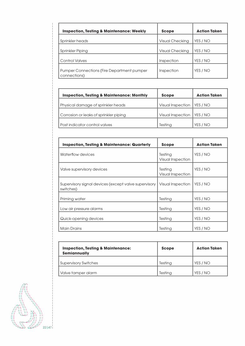
Inspection, Testing & Maintenance: Weekly Scope Action Taken
Sprinkler heads Visual Checking YES / NO
Sprinkler Piping Visual Checking YES / NO
Control Valves Inspection YES / NO
Pumper Connections (Fire Department pumper connections)
Inspection YES / NO
Inspection, Testing & Maintenance: Monthly Scope Action Taken
Physical damage of sprinkler heads Visual Inspection YES / NO
Corrosion or leaks of sprinkler piping Visual Inspection YES / NO
Post indicator control valves Testing YES / NO
Inspection, Testing & Maintenance: Quarterly Scope Action Taken
Waterflow devices TestingVisual Inspection
YES / NO
Valve supervisory devices TestingVisual Inspection
YES / NO
Supervisory signal devices (except valve supervisory switches)
Visual Inspection YES / NO
Priming water Testing YES / NO
Low air pressure alarms Testing YES / NO
Quick-opening devices Testing YES / NO
Main Drains Testing YES / NO
Inspection, Testing & Maintenance: Semiannually
Scope Action Taken
Supervisory Switches Testing YES / NO
Valve tamper alarm Testing YES / NO
23|47
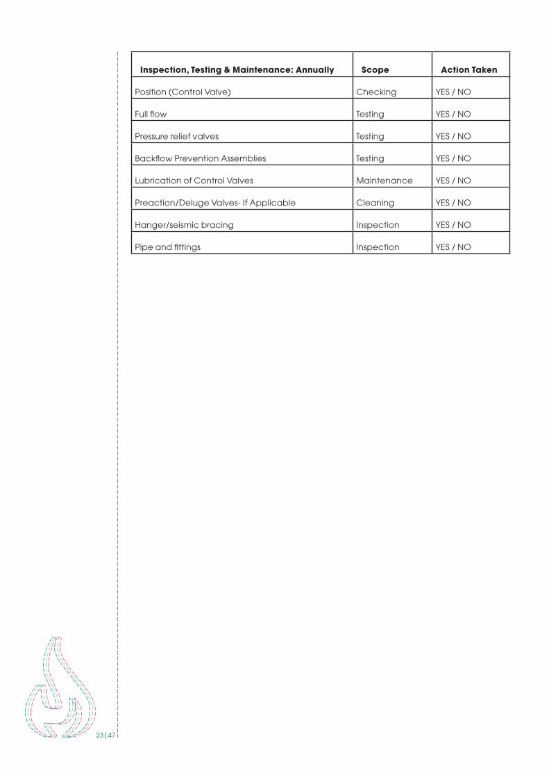
Inspection, Testing & Maintenance: Annually Scope Action Taken
Position (Control Valve) Checking YES / NO
Full flow Testing YES / NO
Pressure relief valves Testing YES / NO
Backflow Prevention Assemblies Testing YES / NO
Lubrication of Control Valves Maintenance YES / NO
Preaction/Deluge Valves- If Applicable Cleaning YES / NO
Hanger/seismic bracing Inspection YES / NO
Pipe and fittings Inspection YES / NO
24|47
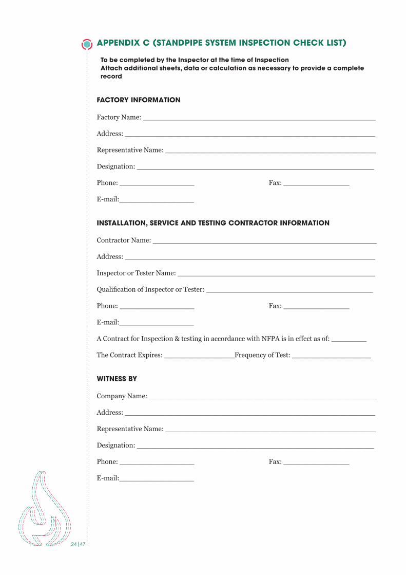
APPENDIX C (STANDPIPE SYSTEM INSPECTION CHECK LIST)
To be completed by the Inspector at the time of InspectionAttach additional sheets, data or calculation as necessary to provide a complete record
FACTORY INFORMATION
Factory Name: _____________________________________________________
Address: _________________________________________________________
Representative Name: ________________________________________________
Designation: ______________________________________________________
Phone: _________________ Fax: _______________
E-mail:_________________
INSTALLATION, SERVICE AND TESTING CONTRACTOR INFORMATION
Contractor Name: ___________________________________________________
Address: _________________________________________________________
Inspector or Tester Name: _____________________________________________
Qualification of Inspector or Tester: ______________________________________
Phone: _________________ Fax: _______________
E-mail:_________________
A Contract for Inspection & testing in accordance with NFPA is in effect as of: ________
The Contract Expires: ________________Frequency of Test: __________________
WITNESS BY
Company Name: ____________________________________________________
Address: _________________________________________________________
Representative Name: ________________________________________________
Designation: ______________________________________________________
Phone: _________________ Fax: _______________
E-mail:_________________
25|47
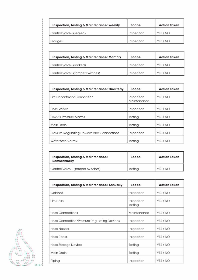
Inspection, Testing & Maintenance: Weekly Scope Action Taken
Control Valve - (sealed) Inspection YES / NO
Gauges Inspection YES / NO
Inspection, Testing & Maintenance: Monthly Scope Action Taken
Control Valve - (locked) Inspection YES / NO
Control Valve - (tamper switches) Inspection YES / NO
Inspection, Testing & Maintenance: Quarterly Scope Action Taken
Fire Department Connection InspectionMaintenance
YES / NO
Hose Valves Inspection YES / NO
Low Air Pressure Alarms Testing YES / NO
Main Drain Testing YES / NO
Pressure Regulating Devices and Connections Inspection YES / NO
Waterflow Alarms Testing YES / NO
Inspection, Testing & Maintenance: Semiannually
Scope Action Taken
Control Valve – (tamper switches) Testing YES / NO
Inspection, Testing & Maintenance: Annually Scope Action Taken
Cabinet Inspection YES / NO
Fire Hose InspectionTesting
YES / NO
Hose Connections Maintenance YES / NO
Hose Connection/Pressure Regulating Devices Inspection YES / NO
Hose Nozzles Inspection YES / NO
Hose Racks Inspection YES / NO
Hose Storage Device Testing YES / NO
Main Drain Testing YES / NO
Piping Inspection YES / NO

26|47
Pressure Reducing Valves Inspection YES / NO
Valves (all types) Maintenance YES / NO
Inspection, Testing & Maintenance: Annually Scope Action Taken
Flow Test Most Remote Hose Connection Testing YES / NO
Hydrostatic Test (dry systems or pipe) Testing YES / NO
Pressure Control Valve Testing YES / NO
Pressure Reducing Valve Testing YES / NO

27|47
APPENDIX D (FIRE PUMP SYSTEM INSPECTION CHECK LIST)
To be completed by the Inspector at the time of InspectionAttach additional sheets, data or calculation as necessary to provide a complete record
FACTORY INFORMATION
Factory Name: _____________________________________________________
Address: _________________________________________________________
Representative Name: ________________________________________________
Designation: ______________________________________________________
Phone: _________________ Fax: _______________
E-mail:_________________
INSTALLATION, SERVICE AND TESTING CONTRACTOR INFORMATION
Contractor Name: ___________________________________________________
Address: _________________________________________________________
Inspector or Tester Name: _____________________________________________
Qualification of Inspector or Tester: ______________________________________
Phone: _________________ Fax: _______________
E-mail:_________________
A Contract for Inspection & testing in accordance with NFPA is in effect as of: __________
The Contract Expires: ________________Frequency of Test: ___________________
WITNESS BY
Company Name: ____________________________________________________
Address: _________________________________________________________
Representative Name: ________________________________________________
Designation: ______________________________________________________
Phone: _________________ Fax: _______________
E-mail:_________________

28|47
Diesel Engine System
Inspection, Testing & Maintenance: Weekly
Scope Action Taken
Tank level Visual Inspection Checking
YES / NO
Tank float switch Visual InspectionTesting
YES / NO
Solenoid valve operation Visual InspectionTesting
YES / NO
Water in system CheckingCleaning
YES / NO
Flexible hoses and connectors Visual Inspection YES / NO
Oil level Visual InspectionChecking
YES / NO
Lube oil heater Checking YES / NO
Level (Cooling system) Visual InspectionChecking
YES / NO
Adequate cooling water to heat exchanger
Checking YES / NO
Water pump(s) Visual Inspection YES / NO
Condition of flexible hoses and connections
Visual InspectionChecking
YES / NO
Jacket water heater Checking YES / NO
Leakage (Exhaust system) Visual InspectionChecking
YES / NO
Drain condensate trap Checking YES / NO
Electrolyte level (Battery system) Checking YES / NO
General inspection Visual Inspection YES / NO
Pump house, heating ventilating louvers
Visual InspectionChecking
YES / NO
Electrical System
Inspection, Testing & Maintenance: Monthly
Scope Action Taken
Exercise isolating switch and circuit breaker
Visual InspectionChecking
YES / NO
29|47
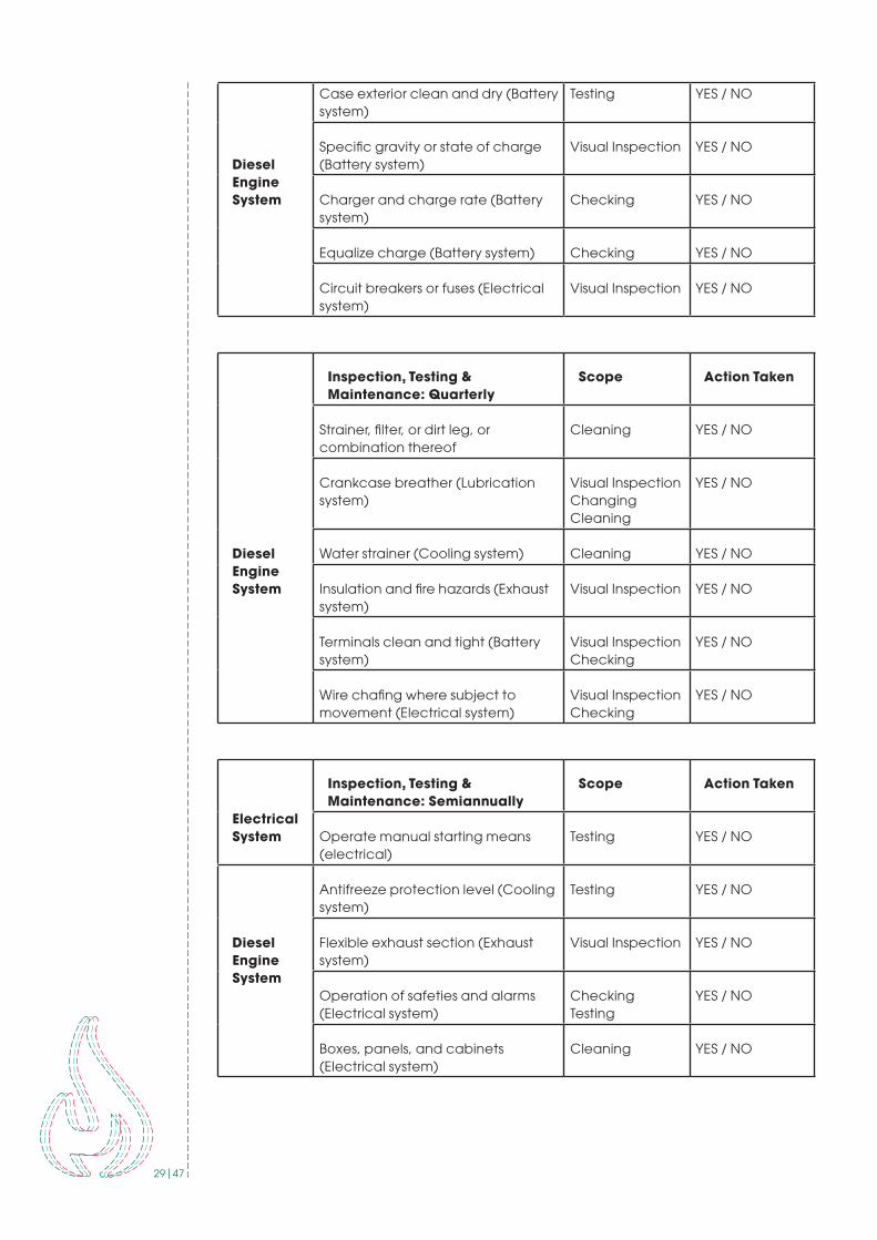
Diesel Engine System
Case exterior clean and dry (Battery system)
Testing YES / NO
Specific gravity or state of charge (Battery system)
Visual Inspection YES / NO
Charger and charge rate (Battery system)
Checking YES / NO
Equalize charge (Battery system) Checking YES / NO
Circuit breakers or fuses (Electrical system)
Visual Inspection YES / NO
Diesel Engine System
Inspection, Testing & Maintenance: Quarterly
Scope Action Taken
Strainer, filter, or dirt leg, or combination thereof
Cleaning YES / NO
Crankcase breather (Lubrication system)
Visual InspectionChangingCleaning
YES / NO
Water strainer (Cooling system) Cleaning YES / NO
Insulation and fire hazards (Exhaust system)
Visual Inspection YES / NO
Terminals clean and tight (Battery system)
Visual InspectionChecking
YES / NO
Wire chafing where subject to movement (Electrical system)
Visual InspectionChecking
YES / NO
Electrical System
Inspection, Testing & Maintenance: Semiannually
Scope Action Taken
Operate manual starting means (electrical)
Testing YES / NO
Diesel Engine System
Antifreeze protection level (Cooling system)
Testing YES / NO
Flexible exhaust section (Exhaust system)
Visual Inspection YES / NO
Operation of safeties and alarms (Electrical system)
CheckingTesting
YES / NO
Boxes, panels, and cabinets (Electrical system)
Cleaning YES / NO

30|47
Pump System
Inspection, Testing & Maintenance: Annually
Scope Action Taken
Lubricate pump bearings Changing YES / NO
Check pump shaft end play Checking YES / NO
Check accuracy of pressure gauges and sensors
CheckingChanging
YES / NO
Check pump coupling alignment Checking YES / NO
Mechanical Transmission
Lubricate coupling Changing YES / NO
Lubricate right-angle gear drive Changing YES / NO
Electrical System
Trip circuit breaker (if mechanism provided)
Testing YES / NO
Inspect and operate emergency manual starting means (without power)
Visual InspectionTesting
YES / NO
Tighten electrical connections as necessary
Checking YES / NO
Lubricate mechanical moving parts (excluding starters and relays)
Checking YES / NO
Calibrate pressure switch settings Checking YES / NO
Grease motor bearings Changing YES / NO
Diesel Engine System
Water and foreign material in tank Cleaning YES / NO
Tank vents and overflow piping unobstructed
CheckingTesting
YES / NO
Piping Visual Inspection YES / NO
Rod out heat exchanger Cleaning YES / NO
Inspect duct work, clean louvers (combustion air) (Cooling system)
Visual InspectionCheckingChanging
YES / NO
Excessive back pressure (Exhaust system)
Testing YES / NO
Exhaust system hangers and supports (Exhaust system)
Visual Inspection YES / NO
Clean terminals (Battery system) Cleaning YES / NO
Tighten control and power wiring connections (Battery system)
Checking YES / NO

31|47
Diesel Engine System
Inspection, Testing & Maintenance: Annually
Scope Action Taken
Oil change Changing YES / NO
Oil filter(s) Changing YES / NO
32|47
APPENDIX E (FIRE ALARM AND DETECTION SYSTEM INSTALLATION INSPECTION CHECK LIST)
To be completed by the Inspector at the time of InspectionAttach additional sheets, data or calculation as necessary to provide a complete record
FACTORY INFORMATION
Factory Name: _____________________________________________________
Address: _________________________________________________________
Representative Name: ________________________________________________
Designation: ______________________________________________________
Phone: _________________ Fax: _______________
E-mail:_________________
INSTALLATION, SERVICE AND TESTING CONTRACTOR INFORMATION
Contractor Name: ___________________________________________________
Address: _________________________________________________________
Inspector or Tester Name: _____________________________________________
Qualification of Inspector or Tester: ______________________________________
Phone: _________________ Fax: _______________
E-mail:_________________
A Contract for Inspection & testing in accordance with NFPA is in effect as of: __________
The Contract Expires: ________________Frequency of Test: ___________________
WITNESS BY
Company Name: ____________________________________________________
Address: _________________________________________________________
Representative Name: ________________________________________________
Designation: ______________________________________________________
Phone: _________________ Fax: _______________
E-mail:_________________
33|47
MANUFACTURER INFORMATION
System Manufacturer: ___________________________________________________
Country of Origin: ______________________________________________________
Address: ____________________________________________________________
Local Agent (If any): ___________________________________________________
Local Agent’s Address: __________________________________________________
Local Agent’s Representative Name: _________________________________________
Designation: _________________________________________________________
Phone: _________________ Fax: _______________
E-mail:______________________
SYSTEM INFORMATION
Type of System: Conventional Addressable
Repeater Panel (Specify Location): __________________________________________
Number of Detectors: Smoke Detector: ___________________ Heat Detector: ____________________ Beam Detector: ____________________ Multi Sensor Detector: _______________Others (Specify): __________________________________________
Pull Station: __________________________________________________________
Alarm Sounder (with/without) Flasher: _______________________________________
Horn/Chime/Strobe/Speaker: _____________________________________________
Others (Specify): ______________________________________________________
Battery- Manufacturer: _______________ Type: ____________
Nominal Voltage: __________ Amp/Hour Rating: __________________
Attach additional sheets as necessary to provide a complete record
34|47
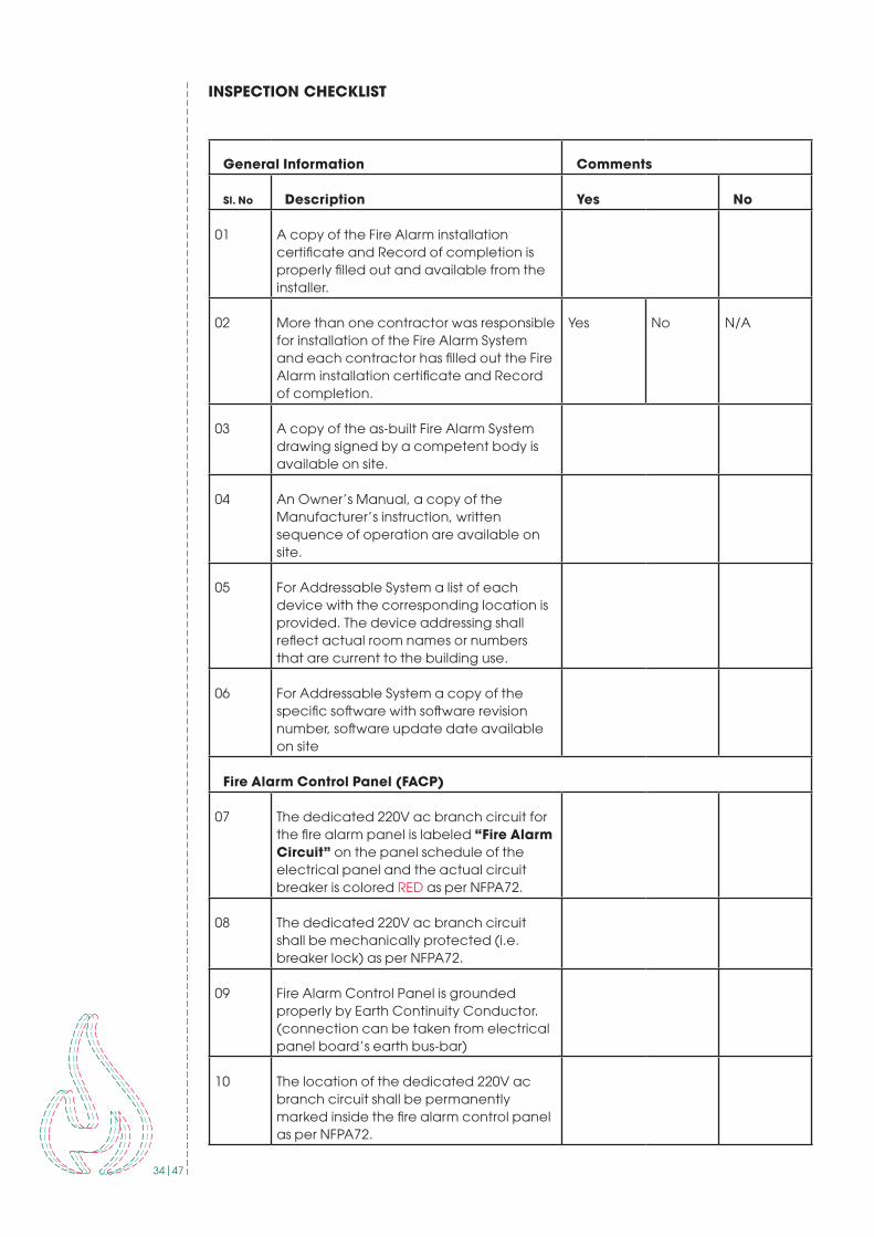
INSPECTION CHECKLIST
General Information Comments
Sl. No Description Yes No
01 A copy of the Fire Alarm installation certificate and Record of completion is properly filled out and available from the installer .
02 More than one contractor was responsible for installation of the Fire Alarm System and each contractor has filled out the Fire Alarm installation certificate and Record of completion .
Yes No N/A
03 A copy of the as-built Fire Alarm System drawing signed by a competent body is available on site .
04 An Owner’s Manual, a copy of the Manufacturer’s instruction, written sequence of operation are available on site .
05 For Addressable System a list of each device with the corresponding location is provided . The device addressing shall reflect actual room names or numbers that are current to the building use .
06 For Addressable System a copy of the specific software with software revision number, software update date available on site
Fire Alarm Control Panel (FACP)
07 The dedicated 220V ac branch circuit for the fire alarm panel is labeled “Fire Alarm Circuit” on the panel schedule of the electrical panel and the actual circuit breaker is colored RED as per NFPA72 .
08 The dedicated 220V ac branch circuit shall be mechanically protected (i .e . breaker lock) as per NFPA72 .
09 Fire Alarm Control Panel is grounded properly by Earth Continuity Conductor . (connection can be taken from electrical panel board’s earth bus-bar)
10 The location of the dedicated 220V ac branch circuit shall be permanently marked inside the fire alarm control panel as per NFPA72 .

35|47
11 A device location and zone map / Schematic Diagram shall be provided at or beside the fire alarm control panel and remote annunciator as per NFPA72 . This Schematic Diagram shall be approved by the competent body .
12 Batteries are permanently marked with Month & Year of manufacture as per NFPA72 .
13 Fire Alarm Control Panel and/or Remote Annunciator receive the correct information when device has been activated . (i .e . device location, device type, alarm type)
Emergency Voice/Alarm Communication Comments
If available check the following Yes No N/A
14 Fire Alarm System is monitored by a monitoring station .
15 Primary communication line is tested and monitoring station receives the proper information from the fire alarm system.
16 Secondary communication line is tested and monitoring station receives the proper information from the fire alarm system .
Notification Devices Comments
Sl. No Description Yes No
17 Fire Alarm signaling devices sound throughout the occupancy .
18 The minimum sound pressure level of 15dBA above the ambient noise level or 5dBA above a maximum sound level lasting for at least 60 seconds, whichever is greater as per NFPA72 .
19 The sound level of sleeping rooms (i .e . dormitory) is at least 15dBA above average ambient sound level or 75dBA measured at the pillow, whichever is greater as per NFPA72 .
20 If sounder with flasher used, flasher is working properly or not .
Initiating Devices
21 All initiating devices have been tested as per manufacturer instructions .
22 All the initiating devices labeled properly .

36|47
23 Smoke Detectors initiate alarm throughout the fire alarm panel.
24 Heat Detectors initiates alarm throughout the fire alarm panel.
25 Pull Stations initiate alarm throughout the fire alarm panel.
26 Duct Detectors shut down HVAC unit and send a supervisory signal to the fire alarm panel .
Yes No N/A
27 Are Smoke Detectors are installed instead of Duct Detectors and shut down all HVAC units when detectors activate .
Yes No N/A
28 Clean Agent Suppression system initiates alarm throughout the fire alarm panel.
Yes No N/A
Sprinkler System Comments
Sl. No Description Yes No
29 Sprinkler flow switch initiates alarm through the fire alarm panel.
30 All control valves for the sprinkler system are monitored and the movement of the valve initiates a trouble signal at the fire alarm panel .
31 Low air pressure for the sprinkler system sends a trouble signal to the fire alarm panel .
32 For sprinkler system with a pressure tank, the high and low pressure of the tank sends a supervisory signal to the fire alarm panel .
Fire Pump
33 When the fire pump is running a supervisory signal is sent to the fire alarm panel .
34 When there is a loss of any phase at the line terminals of the motor contactor of the electric driven fire pump a supervisory signal is sent to the fire alarm panel.
35 Phase reversal of the electric supply to the electric driven fire pump shall send a supervisory signal is sent to the fire alarm panel .
36 Pump room temperature is controlled by exhaust fan .
37|47
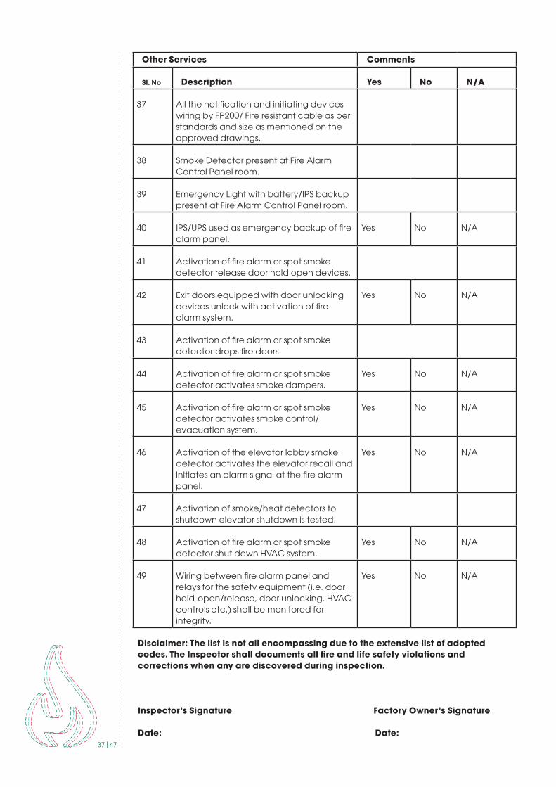
Other Services Comments
Sl. No Description Yes No N/A
37 All the notification and initiating devices wiring by FP200/ Fire resistant cable as per standards and size as mentioned on the approved drawings .
38 Smoke Detector present at Fire Alarm Control Panel room .
39 Emergency Light with battery/IPS backup present at Fire Alarm Control Panel room .
40 IPS/UPS used as emergency backup of fire alarm panel .
Yes No N/A
41 Activation of fire alarm or spot smoke detector release door hold open devices .
42 Exit doors equipped with door unlocking devices unlock with activation of fire alarm system .
Yes No N/A
43 Activation of fire alarm or spot smoke detector drops fire doors.
44 Activation of fire alarm or spot smoke detector activates smoke dampers .
Yes No N/A
45 Activation of fire alarm or spot smoke detector activates smoke control/evacuation system .
Yes No N/A
46 Activation of the elevator lobby smoke detector activates the elevator recall and initiates an alarm signal at the fire alarm panel .
Yes No N/A
47 Activation of smoke/heat detectors to shutdown elevator shutdown is tested .
48 Activation of fire alarm or spot smoke detector shut down HVAC system .
Yes No N/A
49 Wiring between fire alarm panel and relays for the safety equipment (i .e . door hold-open/release, door unlocking, HVAC controls etc .) shall be monitored for integrity .
Yes No N/A
Disclaimer: The list is not all encompassing due to the extensive list of adopted codes. The Inspector shall documents all fire and life safety violations and corrections when any are discovered during inspection.
Inspector’s Signature Factory Owner’s Signature
Date: Date:

38|47
APPENDIX F (EMERGENCY & EXIT LIGHTING MAINTENANCE INSPECTION CHECKLIST)
To be completed by the Inspector at the time of InspectionAttach additional sheets, data or calculation as necessary to provide a complete record
FACTORY INFORMATION
Factory Name: _____________________________________________________
Address: _________________________________________________________
Representative Name: ________________________________________________
Designation: ______________________________________________________
Phone: _________________ Fax: _______________
E-mail:_________________
INSTALLATION, SERVICE AND TESTING CONTRACTOR INFORMATION (IF APPLICABLE)
Contractor Name: ___________________________________________________
Address: _________________________________________________________
Inspector or Tester Name: _____________________________________________
Qualification of Inspector or Tester: ______________________________________
Phone: _________________ Fax: _______________
E-mail:_________________
A Contract for Inspection & testing in accordance with NFPA is in effect as of: ________
The Contract Expires: ________________Frequency of Test: __________________
WITNESS BY
Company Name: ____________________________________________________
Address: _________________________________________________________
Representative Name: ________________________________________________
Designation: ______________________________________________________
Phone: _________________ Fax: _______________
E-mail:_________________
As per NFPA standard No. 101-31-1.3.7, A functional test shall be conducted on every required emergency lighting system at 30-day intervals for a minimum of 30 seconds. An annual test shall be conducted for the 1 1/2 hour duration. Equipment shall be fully operational for the duration of the test. Written records of visual inspections and tests shall be kept by the owner for inspection by the authority having jurisdiction.
39|47
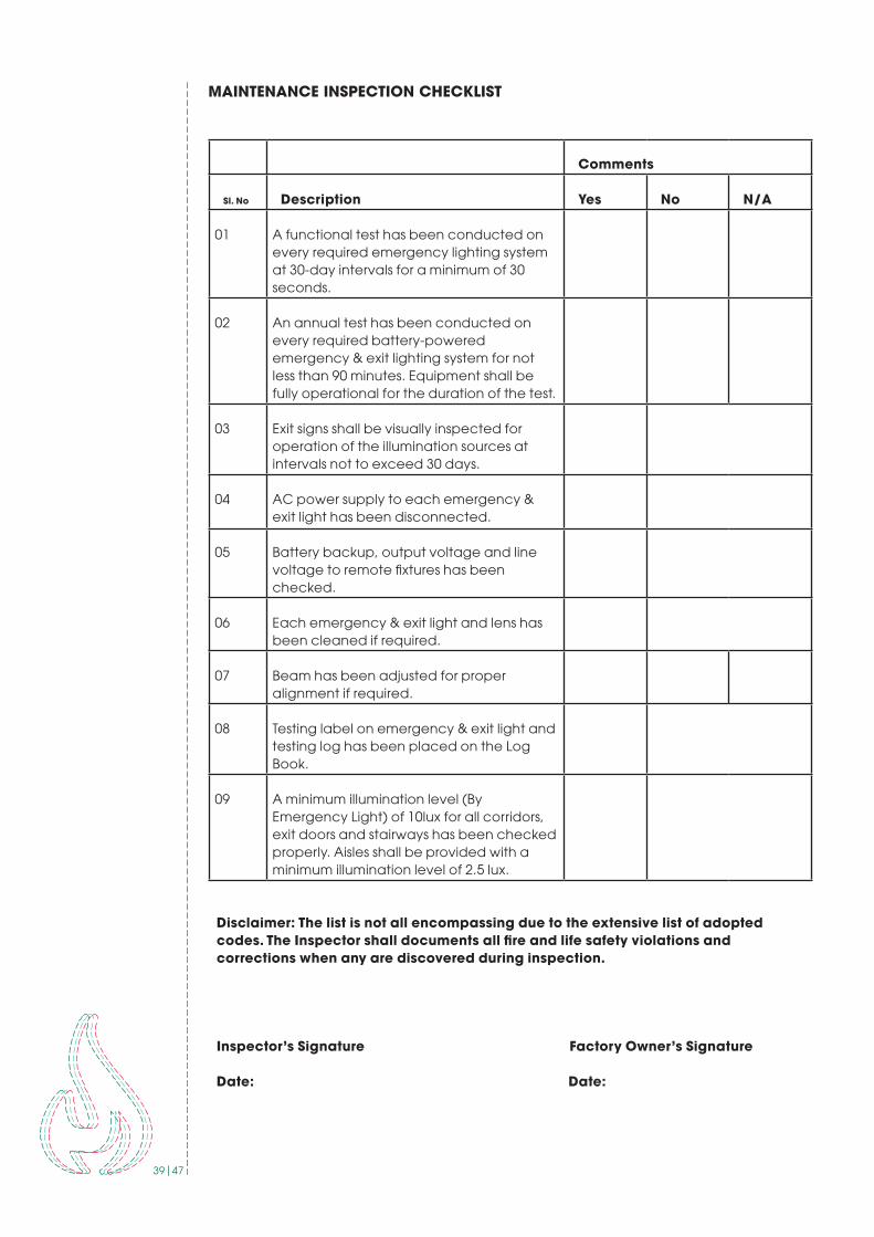
MAINTENANCE INSPECTION CHECKLIST
Comments
Sl. No Description Yes No N/A
01 A functional test has been conducted on every required emergency lighting system at 30-day intervals for a minimum of 30 seconds .
02 An annual test has been conducted on every required battery-powered emergency & exit lighting system for not less than 90 minutes . Equipment shall be fully operational for the duration of the test .
03 Exit signs shall be visually inspected for operation of the illumination sources at intervals not to exceed 30 days .
04 AC power supply to each emergency & exit light has been disconnected .
05 Battery backup, output voltage and line voltage to remote fixtures has been checked .
06 Each emergency & exit light and lens has been cleaned if required .
07 Beam has been adjusted for proper alignment if required .
08 Testing label on emergency & exit light and testing log has been placed on the Log Book .
09 A minimum illumination level (By Emergency Light) of 10lux for all corridors, exit doors and stairways has been checked properly . Aisles shall be provided with a minimum illumination level of 2 .5 lux .
Disclaimer: The list is not all encompassing due to the extensive list of adopted codes. The Inspector shall documents all fire and life safety violations and corrections when any are discovered during inspection.
Inspector’s Signature Factory Owner’s Signature
Date: Date:
40|47
APPENDIX G (GUIDELINE FOR FIRE DOOR SELECTION)
WHAT FIRE DOORS DO?
• Fire doors save lives and property• They are part of a building’s passive fi re protection system and are fundamental to most fi re strategies for buildings• They provide critical protection within a building such as escape routes (stairs and corridors) and in protecting from fi re hazards in a building.
WHAT’S IMPORTANT ABOUT FIRE DOORS?
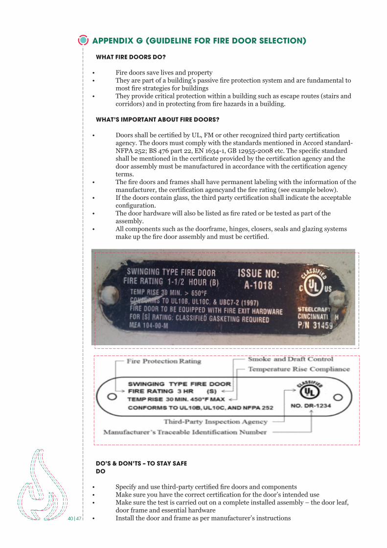
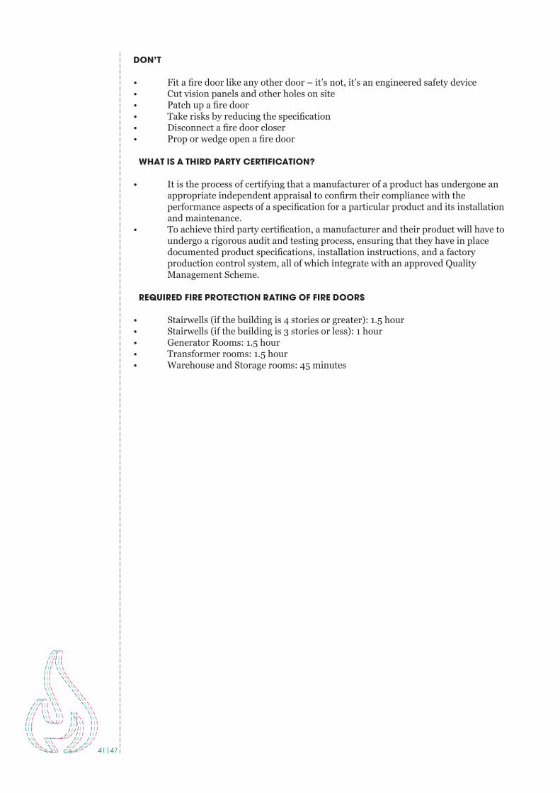
• Doors shall be certifi ed by UL, FM or other recognized third party certifi cation agency. The doors must comply with the standards mentioned in Accord standard- NFPA 252; BS 476 part 22, EN 1634-1, GB 12955-2008 etc. The specifi c standard shall be mentioned in the certifi cate provided by the certifi cation agency and the door assembly must be manufactured in accordance with the certifi cation agency terms.• The fi re doors and frames shall have permanent labeling with the information of the manufacturer, the certifi cation agencyand the fi re rating (see example below).• If the doors contain glass, the third party certifi cation shall indicate the acceptable confi guration.• The door hardware will also be listed as fi re rated or be tested as part of the assembly.• All components such as the doorframe, hinges, closers, seals and glazing systems make up the fi re door assembly and must be certifi ed.
EXAMPLE OF FIRE DOOR RATING LABEL
DO’S & DON’TS – TO STAY SAFEDO
• Specify and use third-party certifi ed fi re doors and components• Make sure you have the correct certifi cation for the door’s intended use• Make sure the test is carried out on a complete installed assembly – the door leaf, door frame and essential hardware• Install the door and frame as per manufacturer’s instructions
EXAMPLE OF FIRE DOOR RATING LABEL
41|47
DON’T
• Fit a fire door like any other door – it’s not, it’s an engineered safety device• Cut vision panels and other holes on site• Patch up a fire door• Take risks by reducing the specification• Disconnect a fire door closer• Prop or wedge open a fire door
WHAT IS A THIRD PARTY CERTIFICATION?
• It is the process of certifying that a manufacturer of a product has undergone an appropriate independent appraisal to confirm their compliance with the performance aspects of a specification for a particular product and its installation and maintenance. • To achieve third party certification, a manufacturer and their product will have to undergo a rigorous audit and testing process, ensuring that they have in place documented product specifications, installation instructions, and a factory production control system, all of which integrate with an approved Quality Management Scheme.
REQUIRED FIRE PROTECTION RATING OF FIRE DOORS
• Stairwells (if the building is 4 stories or greater): 1.5 hour • Stairwells (if the building is 3 stories or less): 1 hour • Generator Rooms: 1.5 hour• Transformer rooms: 1.5 hour• Warehouse and Storage rooms: 45 minutes

42|47
APPENDIX H (DESIGN SUBMISSION CRITERIA)
FIRE ALARM SYSTEM
As per ACCORD standard Part 5, section 5.7 Fire Alarm System Design to be verified by ACCORD Chief Safety Inspector. Testing of the installation shall be conducted in accordance with NFPA72 acceptance testing requirements. Documents of all testing shall be submitted for review to the Chief Safety Inspector. The Owner shall notify ACCORD prior to conducting final acceptance testing of the Fire Alarm System installation to allow the ACCORD the option of witnessing this testing and conduct a final inspection of the installation.
The factory has to submit the drawings for Accord review as per following design submission criteria:
A. Product Data: Product data submittal shall include the following as minimum:1. Schedule of equipment proposed, with catalog reference number.2. Name and address of the manufacturer and country of origin of the product.3. Complete catalog pages of proposed equipment.4. Name and address of the authorized local representative/ dealer.5. Battery: Sizing calculations.6. Voltage Drop calculations.7. Other required calculation such as line resistance calculation where required.
B. Shop Drawing: Each shop drawing submittal shall include two sets of complete plans on minimum A2 size paper and the following as minimum:
1. Factory Forwarding Letter with factory name, address and contacts.2. The drawing’s cover page shall include Factory name, address and Accord ID; Designer name and address; Contractor name and address. 3. Each and every page of shop drawing to be stamped and signed by factory’s concern authority/ representative.4. Include a point of compass (North direction) on the drawing.5. Include legends of fire alarm system’s detecting, notification and interfacing devices as per NFPA170.6. Include dimensioned site plan with all necessary information such as FACP location, outdoor cable route including cable and its installation details etc.7. Detailed floor layouts drawn to scale showing all peripherals with label reference, primary power connection location & door, window, wall partitions, exhaust fans, cable risers, air source, light source locations etc., and exact routing of cabling, wire ways, and detection and evacuation zoning. Mention room description/ purpose of each and every area of the factory building/entire premises.8. Include details of ceiling geometries such as clear ceiling height, beam depth, solid joists and all partitions extending to within 15 percent of the ceiling height should be mention on the drawing. Architectural elevation is required in case of shed building.9. Include storage description such as rack height, ceiling height where required. Provide rack storage elevation if possible. 10. Include locations of fire alarm control panel, repeater panel (if applicable) detecting and notification devices, interfacing devices in ceiling and reflected ceilings including elevation and typical installation details. 11. Signaling line circuits, initiating device circuit and notification appliances circuit shall have to be separate.12. Detailed system schematic diagram. Include diagrams for equipment and for system with all terminals and interconnections identified.13. Include device address list: Coordinate with final system programming and labeling.14. Cause and Effect Matrix: Show in a matrix format, the effect of every initiating device on the FACP, notification devices, system peripherals & auxiliary systems interfaced with it.15. All cables to be used in the purpose of Fire Alarm System shall have to be as per Article 760 of NFPA 70. The cable for Notification Appliance Circuits shall have to contain a minimum 2-hour fire-resistive rating with minimum pathway survivability level 2 as per NFPA 72- Chapter 12 (12.4.3 & 12.4.4) and NFPA 70 –760. For Initiating Device circuit or Signaling Line Circuits minimum 2 core, 1.5 mm2 cable shall be used as per NFPA 70- Table 760.154.

43|47
Alarm Cable marking shall be as per NFPA 70-760.179 (I). All Fire Alarm Cables shall be tested and certified by recognized third party.16. Lift, Sprinkler Zone Control Valve, HVAC system, exhaust fan, valves controlling water supplies shall be interfaced with fire alarm system. 17. Connect signals from the fire pump controllers to the fire alarm system to provide a positive indication of pump running, loss of power, phase reversal, and loss of phase. Monitor fuel levels and battery charging for diesel engine-driven fire pumps. And monitor the water level of tanks and reservoirs to ensure the maintenance of an adequate reserve for firefighting.18. Provide automatic fire detection in concealed spaces used for mechanical and plumbing systems. Heat detectors work best in these areas.
Recommendations:1. If the factory wants to keep the fire door open “Door Hold Open device” to be used which shall be interfaced with fire alarm system in such a way that in case of fire the door will be closed automatically getting the signal from Fire Alarm Panel. It should be clearly shown on the drawing.2. Multi sensor detectors or heat detector are recommended on the sewing, cutting, iron, knitting& finishing and other areas where there is a possibility of floating fabric dust, threads and cottons etc. to avoid false alarm.3. Air Sampling System (Aspiration, Vesda) is recommended for the floors with high heights eg warehouses, dying sheds and other double height areas.4. Avoid installing smoke detectors in areas exposed to moisture, high temperatures, or airborne contaminants such as dust, fumes, or vapors, including toilet blocks, loading docks, and vehicle parking areas.
Re-submittals: The rejected drawing should be resubmitted within 15 days of email received with necessary corrections as mentioned on the design review comments. Submittals requiring additional information will be placed “on hold” until required information has been submitted. Plan information revisions shall be submitted with changes clouded. Changes in other documents shall be clearly identified.
If there is any major modification or correction on the drawing, the drawing shall be resubmitted for ACCORD’s review.
Record DrawingsOne month prior to the issue of the “hand-over certificate” the Contractor shall provide the fully detailed “As Built” drawings of the whole of the works together with all working and maintenance instruction.
It shall be the responsibility of Contractor to ensure that a set of up to date accurate record drawings are submitted to the Consultant “As Installed” status of the works. The drawings shall be regularly updated at intervals not exceeding one week and will be subject to inspection at any time by the Engineer.
The “As Built” drawings shall show the followings:a) 1:100 or 1:50 scale drawings and schematic diagram of complete installation showing all switchgear and distribution with the appropriate code letters and identification marks. b) The location of the supply authority connection provided within the contract whether carried out by the Contractor or by appropriate authority, together with the points of origin and termination, size and type of cables.c) The layout, location and extent of all Detectors showing that the type in accordance with the schedule of the detectors and other outletsd) Manufacturer drawings showing the arrangement and assembly of component parts of all machines and of equipment which may need servicing.e) Layouts giving circuit details including circuit reference, origin, route, distribution and where buried for each cable, conduit, tray and trunking. The circuit reference shall relate to the appropriate cable schedule and distribution board schedule.
44|47
Three prints of each “As Built” drawing shall be issued to the Engineer for approval prior to final issue.
The Contractor’s main Works program must show the dates of submission of draft “As Built” drawings and a three week approval period to ensure that all drawings are approved to enable practical completion which will not be certified if approved drawings are not available. Contractor’s program must show preparation periods for the drawings and the first issue of drawings should occur not less than three months before practical completion date.
Testing: • Submit a test plan for review with the design documents. Ensure the test plan includes 100% acceptance testing of all initiating devices, notification appliances, and circuit wiring in all normal and trouble conditions. Perform operational and calibrated testing of all initiating devices in each mode (normal and trouble). Submit test reports and certificates to the Accord upon completion.
Training: • Verify qualified personnel are available and engaged to inspect, test, and maintain the completed installation, including regular periodic tests of all devices and controls.
Operation and Maintenance Documents: • Deliver complete as-built drawings and operation and maintenance documents to the building owner and factory management, including the manufacturer’s operating instructions. Provide copies of require maintenance and test reports for completion and submission by qualified personnel.
45|47
SPRINKLER AND STANDPIPE SYSTEM
As per ACCORD standard Part 5, section 5.3 & 5.4 Fire Protection System Design to be verified by ACCORD Chief Safety Inspector. Testing of the installation shall be conducted in accordance with NFPA acceptance testing requirements. Documents of all testing shall be submitted for review to the Chief Safety Inspector. The Owner shall notify ACCORD prior to conducting final acceptance testing of the Fire Protection System installation to allow the ACCORD the option of witnessing this testing and conduct a final inspection of the installation.
Shop DrawingEach shop drawing submittal shall include two sets of complete plans on minimum A2 size paper and the following as minimum:• Factory Forwarding Letter with factory name, address and contacts.• The drawing’s cover page shall include Factory name, address and Accord ID; Designer name and address; Contractor name and address. • Each and every page of shop drawing to be stamped and signed by factory’s concern authority/ representative.• Include a point of compass (North direction) on the drawing.• Include legends of each and every firefighting equipment with detail description.• Include dimensioned site plan with all necessary information such as Fire Pump location, outdoor piping route including gate valves and its installation details etc.• Include details of ceiling geometries such as clear ceiling height, beam depth, solid joists and all partitions extending to within 15 percent of the ceiling height should be mentioned on the drawing. Architectural elevation is required in case of shed building.• Include storage description such as rack height, ceiling height where required. Provide rack storage elevation if possible. • Include detailed system schematic diagram. • Include diagrams for equipment and for system.• Include room description and purpose of each and every area.• Include Hazard Classification• Identify hydraulically most remote/demanding area on drawing.
Sprinkler System• Make, type, Model, and nominal K –factor of sprinklers including sprinkler identification number.• Temperature rating and location of high-temperature sprinklers.• Total area of protected by each system on each floor.• Number of sprinklers on each riser per floor.• All design approaches for CMSA, ESFR & Extra large orifice sprinkler systems shall comply with relevant class, commodity & hazard classification plans and calculations as per NFPA 13.• For storage design approach refer to relevant provision CMSA, ESFR & Extra large orifice sprinkler design /Density curve of NFPA -13• Where the equipment is to be installed as an addition to an existing system, enough of the existing system indicated on the plans to make all conditions clear.• Hydraulic calculation shall be submitted along with the design in compliance with NFPA 13; Chapter 23.
Standpipe System• Size and location of standpipe risers, hose outlets and related equipment.• Hose valve manufacture and model.• Pressure – reducing valves manufacturer and model.• Standpipe system demand shall be provided• Hydraulic calculation shall be submitted along with the design in compliance with NFPA 14- Chapter 8.
46|47
Pipe and Fittings• Pipe type and schedule of wall thickness.• Nominal pipe size and cutting lengths of pipe (or center to center dimensions). Where typical line branch lines prevail, it shall be necessary to size only one typical line.• Location and size of riser nipple.• Type of fittings and joints and location of all welds and bends. The contractor shall specify on drawing any section to be shop welded and the type of fittings or formation to be used.• Type and location of hangers, sleeves braces, and methods of securing sprinklers when applicable.• All control valves, check valves, drain pipes, and test connections shall be provided.• The materials for pipes fittings and pipe support shall comply with NFPA-13.• Private fire service main size, lengths, location, weights materials, point of connection to city main; the sizes ,types and locations of valves, valve indicators , regulators, meters, and valve pits; and the depth that the top of the pipe is laid below grade.• Piping Provisions for flushing.
Fire Pump• Fire pump design and installation shall comply with all requirement of NFPA -20
Testing: • Perform all required acceptance tests upon completion of the installation. Submit all test reports and completion certificates required by NFPA 13 to the Accord for review. Ensure tests include a hydrostatic test, an alarm and flow test, supervisory signal tests, and a main drain test.
Training: • Verify qualified personnel are available and engaged to inspect, text, and maintain the completed installation, including regular periodic tests of all devices and controls.
Operations and Maintenance Documents: • Deliver complete as-built drawings and operation and maintenance documents to the building owner and factory management, including the manufacturer’s operating instructions. Provide copies of require maintenance and test reports for completion

47|47
COLOPHON
Title: Manual - FIRE SAFETY - for existing RMG buildingsDate: October 2014 / Updated August 2015Author: Accord Fire Safety TeamGraphic Design: JUSTAR .nlLayout: Iwan Fokin
BANGLADESH ACCORD FOUNDATION
Level 13, AJ HeightsCha 72/1/d, Pragati SaraniNorth Badda, Dhaka - 1212BangladeshTel +88 02 9852093
Keizersgracht 62-641015 CS AmsterdamThe NetherlandsTel +31 (0) 20 520 7431
www .bangladeshaccord .orgcontact@bangladeshaccord .com