Manual Easy 600
230
User Guide EASY 412 EASY 600 Control Relay 11/99 AWB2528-1304-GB 1st published 1998, edition 04/98 2nd published 1999, edition 06/99, 3rd published 1999, edition 11/99, see list of revisions on page II © Moeller GmbH, Bonn Author: Dieter Bauerfeind Editor: Thomas Kracht Translator:Terence Osborn
-
Upload
guillermo-hernandez -
Category
Documents
-
view
237 -
download
0
Transcript of Manual Easy 600

8/6/2019 Manual Easy 600
http://slidepdf.com/reader/full/manual-easy-600 1/229
User Guide
EASY 412EASY 600
Control Relay
11/99 AWB2528-1304-GB
1st published 1998, edition 04/98
2nd published 1999, edition 06/99,
3rd published 1999, edition 11/99, see list of revisions on page II© Moeller GmbH, Bonn
Author: Dieter Bauerfeind
Editor: Thomas Kracht
Translator:Terence Osborn

8/6/2019 Manual Easy 600
http://slidepdf.com/reader/full/manual-easy-600 2/229
Caution!
Dangerous electrical voltage!
I
Before commencing the installation
q Disconnect the power supply of thedevice.
q Ensure that the device cannot beaccidentally restarted.
q Verify isolation from the supply.
q Earth and short circuit.
q Cover or enclose neighbouring units thatare live.
q Follow the engineering instructions(AWA) of the device concerned.
q Only suitably qualified personnel maywork on this device/system.
q Before installation and before touchingthe device ensure that you are free ofelectrostatic charge.
q Connecting cables and signal linesshould be installed so that inductive orcapacitive interference do not impair the
automation functions.q Install automation devices and related
operating elements in such a way thatthey are well protected againstunintentional operation.
q Suitable safety hardware and softwaremeasures should be implemented forthe I/O interface so that a line or wirebreakage on the signal side does notresult in undefined states in theautomation devices.
q Ensure a reliable electrical isolation ofthe low voltage for the 24 volt supply.Only use power supply units complyingwith IEC 60 364-4-41 or HD 384.4.41 S2.
q Deviations of the mains voltage from therated value must not exceed thetolerance limits given in thespecifications, otherwise this may causemalfunction and dangerous operation.
q Emergency stop devices complying with
IEC/EN 60 204-1 must be effective in alloperating modes of the automationdevices. Unlatching the emergency-stopdevices must not cause uncontrolledoperation or restart.
q Devices that are designed for mountingin housings or control cabinets must onlybe operated and controlled after theyhave been installed with the housingclosed. Desktop or portable units must
only be operated and controlled inenclosed housings.
q Measures should be taken to ensure theproper restart of programs interruptedafter a voltage dip or failure. This shouldnot cause dangerous operating stateseven for a short time. If necessary,emergency-stop devices should beimplemented.
IBM is a registered trademark of International
Business Machines Corporation.
All other brand and product names are
trademarks or registered trademarks of the
owner concerned.
All rights reserved, including those of the
translation.
No part of this manual may be reproduced in
any form (printed, photocopy, microfilm or
any otherprocess) or processed, duplicated
or distributed by means of electronicsystems without written permission of
Moeller GmbH, Bonn.
Subject to alterations without notice.

8/6/2019 Manual Easy 600
http://slidepdf.com/reader/full/manual-easy-600 3/229
II 1 1 / 9 9 A W B 2 5 2 8 - 1 3 0 4 G B
List of revisions to AWB
2528-1304 GB
This manual has been completely revised due to the
new “easy” typers. The following table lists the most
important modifications and additions in comparisonto the 06/99 edition.
New types in 06/99 New types in 11/99
EASY-412-DC-TC EASY 619-AC-RC(X)
EASY-412-AC-RC(X) EASY 621-DC-TC(X)
EASY-620-DC-TC EASY 618-AC-RE
EASY-618-AC-RC EASY 620-DC-TE
EASY 200-EASY
Edition date11/99
Page Description New Modifica-tion
Omitted
11 Table
13 Status display
14 Enhanced display, status display
22, 23 Mounting
25 Connecting the power supply
28 ff. Connecting “easy” inputs/outputs
44 Expanding “easy” inputs/outputs
61, 62 Table
187 Scanning for short-circuit and overload
190 ff. Expanding EASY 600
197 ff. Technical Data

8/6/2019 Manual Easy 600
http://slidepdf.com/reader/full/manual-easy-600 4/229
1 1 1 / 9 9 A W B 2 5 2 8 - 1 3 0 4 G B
Contents
1 Instructions for Use 5
Target readership 5
Proper use 5
Hazard categories and warnings 6
Safety instructions 7
Device designation 7
2 “easy” 9
Overview 9
Versions
“easy” operating principle 12
3 Installation 21
Mounting 21
Connecting expansions 24
Terminals 25
Connecting the power supply 25
Connecting the inputs 28Connecting the outputs 39
Connecting relay outputs 39
Connecting transistor outputs 41
Expanding inputs/outputs 44
4 Commissioning 47
Switching on 47
Setting the menu language 47
“easy” operating modes 48Creating your first circuit diagram 49

8/6/2019 Manual Easy 600
http://slidepdf.com/reader/full/manual-easy-600 5/229
Contents
2 1 1 / 9 9 A W B 2 5 2 8 - 1 3 0 4 G B
5 Drawing a Circuit Diagram with “easy” 59
Operation of “easy” 59
Working with contacts and relays 64Function relay types 77
Timing relays 84
Counter relays 90
Time switch 93
Analog comparators 98
Text display 103
Jumps 105
Example circuits 108
6 Saving and Loading Circuit Diagrams 125
Memory card 126
EASY-SOFT 130
7 “easy” Settings 133
Password protection 133
Changing the menu language 139
Changing parameters 140
Setting the time 143
Changing between winter/summer
time (DST) 144
Activating debounce (input delay) 145
Activating and deactivating P buttons 146
Startup behaviour 148
Behaviour when the circuit diagram
is deleted 149
Behaviour during uploading and
downloading to the card or PC 149Possible faults 149
8 Retention 151
Requirements 151
Setting retention 152
Deleting retentive actual values 153
Transfer retentive behaviour 154
Retentive auxiliary relays (markers) 156
Retentive timing relays 161Retentive Up/down counters C7, C8 170

8/6/2019 Manual Easy 600
http://slidepdf.com/reader/full/manual-easy-600 6/229
Contents
3 1 1 / 9 9 A W B 2 5 2 8 - 1 3 0 4 G B
9 Inside “easy” 175
“easy” circuit diagram cycle 175
Determining the cycle time of “easy” circuit diagrams 178
Delay times for inputs and outputs 184
Short-circuit/overload monitoring
with EASY..-DC-T.. 187
Expanding EASY 600 190
10 What Happens If ...? 193
Messages from the “easy” system 194
Possible situations when creatingcircuit diagrams 195
Event 196
11 Technical Data 197
General 197
Power supply 202
Inputs 203
Relay outputs 206
Transistor outputs 208
Cycle time 210
Glossary 213Remote expansion 213
Local expansion 216
Index 217

8/6/2019 Manual Easy 600
http://slidepdf.com/reader/full/manual-easy-600 7/229
4 1 1 / 9 9 A W B 2 5 2 8 - 1 3 0 4 G B

8/6/2019 Manual Easy 600
http://slidepdf.com/reader/full/manual-easy-600 8/229
5 1 1 / 9 9 A W B 2 5 2 8 - 1 3 0 4 G B
1 Instructions for Use
Target readership “easy” must only be installed and connected up by
trained electricians or other persons who are familiar
with the installation of electrical equipment.
Specialist electrical training is needed for
commissioning and creating circuit diagrams. Parts
of the system can be damaged and persons put at
risk if “easy” is connected or programmed
incorrectly, causing active components such asmotors or pressure cylinders to start up.
Proper use “easy” is a programmable control and timing relay
which is used in place of relay and contactor
controls. It must not be used unless it has been
correctly installed.
“easy” is designed to be installed in an enclosure,switch cabinet or distribution board. Both the
power feed and the signal terminals must be laid
and covered so as to prevent accidental contact.
The installation must conform to regulations for
electromagnetic compatibility (EMC).
There must be no risk due to devices being
activated when “easy” is switched on, e.g.
motors starting up or power supplies switchingon unexpectedly.

8/6/2019 Manual Easy 600
http://slidepdf.com/reader/full/manual-easy-600 9/229
Instructions for Use
6 1 1 / 9 9 A W B 2 5 2 8 - 1 3 0 4 G B
Improper use
“easy” must NOT be used to replace safety-related
control devices, such as burner, crane, emergencystop or two-handed controls.
Hazard categories and
warnings
In this manual, the possible hazards are divided into
three different categories.
Information and tips
Warning
Informs you of a hazardous situation that could
result in severe injury or even death if safetyinstructions and measures to prevent the risk are
not followed.
Caution
Refers to a hazardous situation that could result
in injury or damage if care is not taken.
Attention
Indicates a hazardous situation that could resultin damage to the product or components of
connected systems if care is not taken.
Information and tips contain extra useful details
relating to features that go beyond the scope of
the particular chapter.

8/6/2019 Manual Easy 600
http://slidepdf.com/reader/full/manual-easy-600 10/229
Safety instructions
7 1 1 / 9 9 A W B 2 5 2 8 - 1 3 0 4 G B
Safety instructions
Device designation This manual uses the following abbreviated
designations for different easy models:
EASY 412 for
EASY 412-AC-... and EASY 412-D.-...
EASY 600 for
EASY 6..-AC-RC(X)EASY 6..-DC-.C(X)
“easy”-AC for
EASY 412-AC-..
EASY 6..-AC-RC(X)
“easy”-DC for
EASY 412-DC-..
EASY 620/621-DC-.C(X)
“easy”-X for
EASY 412/621-DC-..X
EASY 412/619-AC-..X
Danger of electric shock
Never carry out electrical work on the devicewhile the power supply is switched on.
Always follow the safety rules:
Switch off and isolate
Secure against reclosing
Ensure that the device is no longer live
Cover adjacent live parts

8/6/2019 Manual Easy 600
http://slidepdf.com/reader/full/manual-easy-600 11/229
Instructions for Use
8 1 1 / 9 9 A W B 2 5 2 8 - 1 3 0 4 G B
“easy”-C for
EASY 412-..-.C.
EASY 6..-..-.C.“easy”-E for
EASY ...-AC-.E
EASY ...-DC-.E

8/6/2019 Manual Easy 600
http://slidepdf.com/reader/full/manual-easy-600 12/229
9 1 1 / 9 9 A W B 2 5 2 8 - 1 3 0 4 G B
2 “easy”
Overview “easy” is an electronic control relay with built-in
logic, timer, counter and time switch functions.
“easy” is a control and input device rolled into one
that can perform many different tasks in building and
machine applications.
Circuit diagrams are connected up using ladder
diagrams, and each element is entered directly via
the “easy” display. For example, you can:
Connect make and break contacts in series and
in parallel
Connect output relays and markers,
Define outputs as relays, impulse relays or
latching relays
Select timing relays with different functions
Assign eight up and down countersDisplay any texts with variables,
Track the flow of current in the circuit diagram
Load, save and password-protect circuit
diagrams
Models with the type designation
“EASY...-...-..-.C(X)” offer an additional four 7-day
time switches each allowing up to four On and Off
times.
The DC versions can receive analog signals at two
inputs and evaluate the signals with eight analog
comparators.
If you prefer to wire up “easy” from a PC, then use
EASY-SOFT. EASY-SOFT allows you to create and
test your circuit diagram on the PC. EASY-SOFT
enables you to print out your circuit diagram in DIN, ANSI or “easy” format.

8/6/2019 Manual Easy 600
http://slidepdf.com/reader/full/manual-easy-600 13/229
“easy”
10 1 1 / 9 9 A W B 2 5 2 8 - 1 3 0 4 G B
Versions Overview of “easy”
Power supply
Inputs
Status LED
Buttons
Socket for memory card or PC interface cable Outputs
LCD display
DEL A LT
ESCOK
ESCOK
DEL A LT

8/6/2019 Manual Easy 600
http://slidepdf.com/reader/full/manual-easy-600 14/229
Versions
11 1 1 / 9 9 A W B 2 5 2 8 - 1 3 0 4 G B
“easy” is available
for 24 V DC, EASY...-DC-..
for AC, EASY...-AC-..
in two model sizes:
EASY 412 with 4 space units
EASY 600 with 6 space units
with a time switch, EASY...-..-..C..
with relay outputs, EASY...-..-R..
with transistor outputs, EASY...-DC-T..
only with LED display, EASY...-..-..X
as expansion EASY ...-...E
Model Power supply Inputs Outputs Special features
EASY 412-DC-R 24 V DC 8 digital, 24 V DC2 of which digital/analog
4 relays (upto 8 A)
2 analog inputs 0 to 10 V,retentive
EASY 412-DC-RC 2 analog inputs 0 to 10 V, timeswitch, retentive
EASY 412-DC-TC 4 transistor,max. 0.5 A 2 analog inputs 0 to 10 V, timeswitch, retentive
EASY 412-DC-TCX 2 analog inputs 0 to 10 V, timeswitch, without LCD andbuttons, retentive
EASY 412-AC-R 97 to 264 V DC 8 digital,0 to 264 V AC
4 relays (upto 8 A)
–
EASY 412-AC-RC Time switch
EASY 412-AC-RCX Time switch, without LCD andbuttons
EASY 618-AC-RC 85 to 264 V DC 12 digital,0 to 264 V AC
6 relay (upto 8 A)
Time switch, retentive, textdisplay
EASY 619-AC-RC(X) Time switch, retentive, textdisplay, expandable
EASY 620-DC-TC 24 V DC 12 digital, 24 V DC2 of which digital/analog
8 transistor,max. 0.5 A
2 analog inputs 0 to 10 V, timeswitch, retentive text display
EASY 621-DC-TC(X) 2 analog inputs 0 to 10 V, timeswitch, retentive text display,expandable

8/6/2019 Manual Easy 600
http://slidepdf.com/reader/full/manual-easy-600 15/229
“easy”
12 1 1 / 9 9 A W B 2 5 2 8 - 1 3 0 4 G B
“easy” operating
principle
“easy” operating buttons
Moving through menus and choosing values
Expansions
EASY 620-DC-TE 24 V DC 12 digital, 24 V DC 8 transistor,max. 0.5 A
Expansion
EASY 618-AC-RE 85 to 264 V AC 12 digital,0 to 264 V AC
6 relay (upto 8 A)
Expansion
EASY 200-EASY – – Coupling device for remoteexpansion
Model Power supply Inputs Outputs Special features
DEL: Deletion in a circuit diagram
ALT: Special functions in the circuit
diagram
Cursor buttons ú í ÍÚ:
Move cursor
Select menu points
Set numbers, contacts and valuesOK:Next menu level, store your entry
ESC:Last menu level, cancel your entry
ALTDELDELDELDELDELDELDELDELDELDEL
ESC OK
and
Show System menu
Go to next menu level
Select menu item
Store your entry
Return to last menu level
Cancel your entry since the last OK

8/6/2019 Manual Easy 600
http://slidepdf.com/reader/full/manual-easy-600 16/229
“easy” operating principle
13 1 1 / 9 9 A W B 2 5 2 8 - 1 3 0 4 G B
Selecting the main menu and System menu
Status display
ÍÚ
ú í
Change menu item
Change value
Change positionP button function (if enabled):
úí
Input P1,
Input P3,
ÍÚ
Input P2
Input P4
and
Current selection
flashes in the
“easy” menu
1st menu level
Main menu
1st menu level
System menu
or
1.........12RSMO 10:421......8
12..........
MO 02:00..34....STOP
PROGRAM...PROGRAM..PARAMETERSET CLOCK..
PASSWORD...DEBOUNCE OFFP ONGB D F E I..
PASSWORD...SYSTEMGB D F E I
8/6/2019 Manual Easy 600
http://slidepdf.com/reader/full/manual-easy-600 17/229
“easy”
14 1 1 / 9 9 A W B 2 5 2 8 - 1 3 0 4 G B
EASY 412 status display
EASY 600 status display
Status display for expansion
InputsWeekday
Time
Outputs RUN/STOP mode
â On/ # Off
I12345678ââ###### MOâ### 12:50Q1234 RUN
Inputs
Weekday/Time
Outputs RUN/STOP mode
On: 1, 2, 3, 4 /Off: ...
12..........
MO 02:00..34....STOP
Inputs
Expansion AC expansion ok/P buttons
Weekday/Time
Outputs
On: 1, 2, 3, 4 /Off: ...RS = Expansion functioning correctly
1.........12RS AC P-MO 10:421......8

8/6/2019 Manual Easy 600
http://slidepdf.com/reader/full/manual-easy-600 18/229
“easy” operating principle
15 1 1 / 9 9 A W B 2 5 2 8 - 1 3 0 4 G B
Advanced status display EASY 600
“easy” LED
EASY 412-..-..X, EASY 600 and “easy”-E feature an
LED on the front indicating the power supply status
as well as whether Run or Stop mode is active
(see Figure on page 10 ).
Retention/Debounce AC expansion ok/P buttons
Startup behaviour
RE = Retention switched onI = Debounce switched off AC = AC expansion functioning correctlyDC = DC expansion functioning correctly
GW= Bus coupling moduleST = When the power supply is switched on, EASY switches to Stop mode
12...6.89..12RE I AC P-MO 14:42 ST12345678 RUN
LED OFF No power supply
LED continuouslylit
Power supply present, Stop mode
LED flashing Power supply present, Run mode

8/6/2019 Manual Easy 600
http://slidepdf.com/reader/full/manual-easy-600 19/229
“easy”
16 1 1 / 9 9 A W B 2 5 2 8 - 1 3 0 4 G B
Menu structure
Main menu without password protection
ParametersPROGRAMDELETE PROGCARD...
Main menu
Parameters
Parameter display
SET CLOCKSUMMER TIME
DEVICE-CARDCARD-DEVICEDELETE CARD
PROGRAM...RUNPARAMETERSET CLOCK..
DELETE ?
REPLACE ?
PROGRAMDELETE PROGCARD...
PROGRAMDELETE PROGCARD...
DEVICE- CARDCARD-DEVICEDELETE CARD
DELETE ?
DEVICE- CARDCARD-DEVICEDELETE CARD
RUN
STOP
PROGRAM...RUNPARAMETERSET CLOCK..
PROGRAM...RUNPARAMETERSET CLOCK..
REPLACE ?
SUMMER TIME
WINTER TIME
SET CLOCKSUMMER TIME
STOP
STOP: CCCCiiiirrrrccccuuuuiiiitttt ddddiiiiaaaaggggrrrraaaammmm ddddiiiissssppppllllaaaayyyyRUN: PPPPoooowwwweeeerrrr f ff flllloooowwww ddddiiiissssppppllllaaaayyyy
RUN Parameterdisplay
Display forclock setting
WINTER TIMEDAY : MOTIME : 14:05
PROGRAM...RUNPARAMETERSET CLOCK..
Circuit diagram

8/6/2019 Manual Easy 600
http://slidepdf.com/reader/full/manual-easy-600 20/229

8/6/2019 Manual Easy 600
http://slidepdf.com/reader/full/manual-easy-600 21/229
“easy”
18 1 1 / 9 9 A W B 2 5 2 8 - 1 3 0 4 G B
EASY 412 System menu, from operating system
V 1.2, EASY 600
ENGLISH
GB D F E I
System menu
CHANGE PWACTIVATE
Password entry
Change password
Change/delete password
CHANGE PW
ACTIVATE ACTIVATE
DEBOUNCE OFF
DEBOUNCE ON
PASSWORD...SYSTEMGB D F E I..
PASSWORD...SYSTEMGB D F E I..
DEUTSCH
FRANCAIS
ESPANOL
ITALIANO
PasswordPASSWORD...SYSTEMGB D F E I..
DEBOUNCE OFFP ONSTOP MODERETENTION ONDEBOUNCE OFFP ONSTOP MODE
RETENTION ONDEBOUNCE OFFP ONSTOP MODERETENTION ONDEBOUNCE OFFP ONSTOP MODERETENTION ON
P ON
P OFF
STOP MODE
RUN MODE
RETENTION ON2
RETENTION OFF2
PORTUGUES1
NEDERLAND1
SVENSKA1
POLSKI1
TURKCE11 Only EASY 600
2 only inStop mode
Password entry
Password

8/6/2019 Manual Easy 600
http://slidepdf.com/reader/full/manual-easy-600 22/229
“easy” operating principle
19 1 1 / 9 9 A W B 2 5 2 8 - 1 3 0 4 G B
Selecting or toggling between menu items
Cursor display
Setting values
CursorÍÚ
Select or
toggle
The cursor blinks:
Full cursor ê / :Move cursor with ú í,In circuit diagram also with
ÍÚ
Value M / MChange position with ú íChange values with
ÍÚBlinking values/menus are
shown grey in this manual.
Change value ÍÚ
Move cursor upand down ú íChange position
ÍÚStore entries
Retain previous
value
PROGRAM...PROGRAM..PARAMETERSET CLOCK..
WINTER TIMEDAY : MOTIME : 01ê25
WINTER TIMEDAY : MOTIME : 01:25
WINTER TIME
DAY : MOTIME : 01:25
Values
Digits
Value of digit

8/6/2019 Manual Easy 600
http://slidepdf.com/reader/full/manual-easy-600 23/229
20 1 1 / 9 9 A W B 2 5 2 8 - 1 3 0 4 G B
8/6/2019 Manual Easy 600
http://slidepdf.com/reader/full/manual-easy-600 24/229
21 1 1 / 9 9 A W B 2 5 2 8 - 1 3 0 4 G B
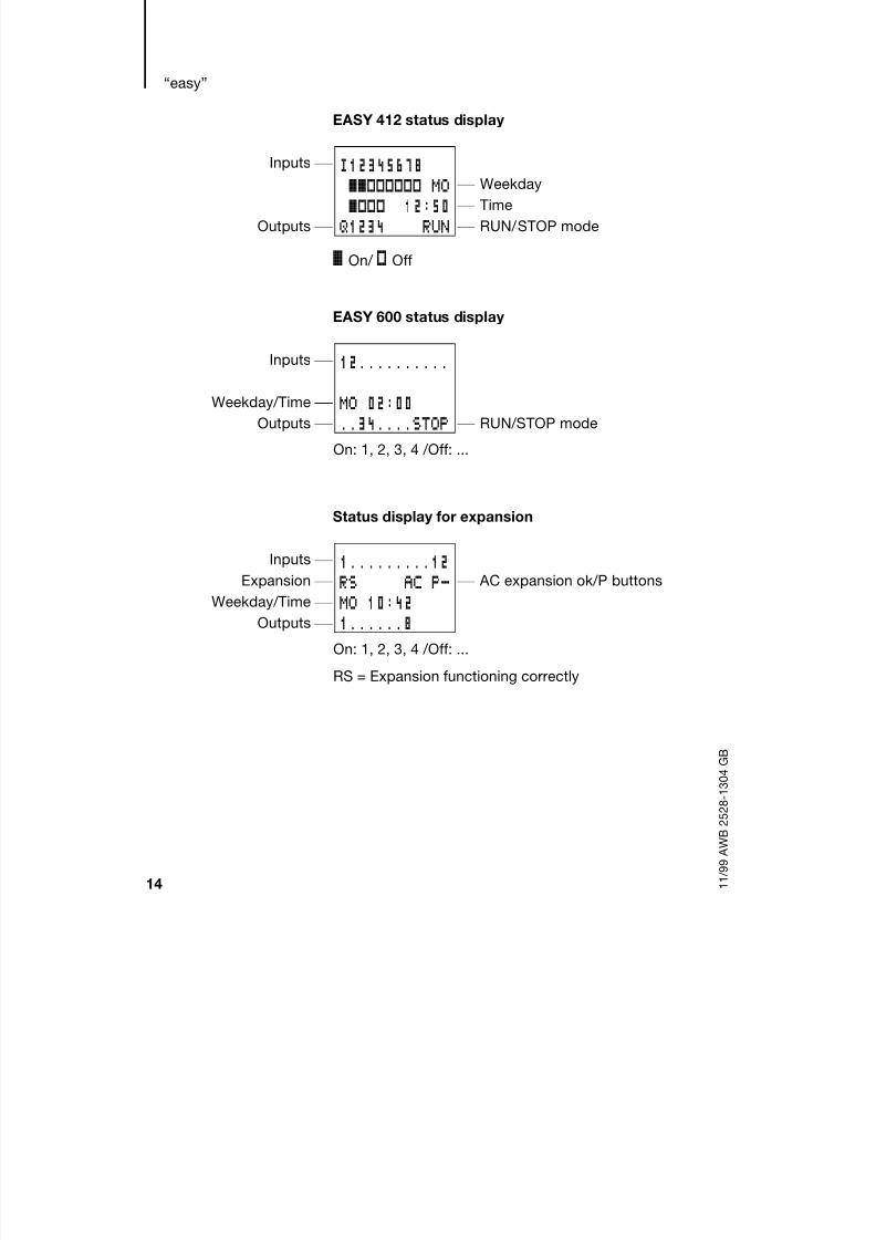
3 Installation
“easy” must only be installed and wired up by trained
electricians or other persons familiar with the
installation of electrical equipment.
“easy” is installed in the following order:
MountingWiring up the inputs
Wiring up the outputs
Connecting the power supply
Mounting Install “easy” in an enclosure, switch cabinet or
distribution board so that the power feed and
terminal connections cannot be touched accidentallyduring operation.
Clip “easy” onto a DIN EN 50 022 top-hat rail or fix
“easy” in place using mounting feet. “easy” can be
mounted either vertically or horizontally.
DANGER of electric shock
Never carry out electrical work on the device
while the power supply is switched on.
Always follow the safety rules:
Switch off and isolate
Secure against reclosing
Ensure that the device is no longer live
Cover adjacent live parts
When using “easy” with expansion units, connect
the expansion concerned before mounting (see
page 24).
8/6/2019 Manual Easy 600
http://slidepdf.com/reader/full/manual-easy-600 25/229
Installation
22 1 1 / 9 9 A W B 2 5 2 8 - 1 3 0 4 G B
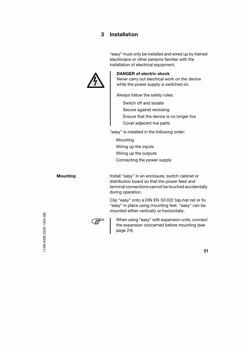
For ease of wiring, leave a gap of at least 3 cm
between “easy” terminals and the wall or adjacent
devices.
Mounting on top-hat rail
Hook “easy” to the top
edge of the top-hat rail and
hinge into place while
pressing down slightly as
shown by the arrows.
Press down lightly on both
the device and the top-hat
rail until “easy” snaps over
the lower edge of the top-
hat rail.
“easy” will clip into place andwill be secured by the built-in
spring mechanism without
needing screws.
Check that “easy” is seated firmly.
“easy” is mounted vertically on a top-hat rail in the
same way.
3 0
3 0
3030
1
2

8/6/2019 Manual Easy 600
http://slidepdf.com/reader/full/manual-easy-600 26/229
Mounting
23 1 1 / 9 9 A W B 2 5 2 8 - 1 3 0 4 G B
Mounting on a mounting plate
For a screw fixing use mounting feet that can be
fitted to the back of the “easy”. Mounting feet can beordered as an accessory.
EASY 200-EASY: EASY 412: EASY 600:

8/6/2019 Manual Easy 600
http://slidepdf.com/reader/full/manual-easy-600 27/229
Installation
24 1 1 / 9 9 A W B 2 5 2 8 - 1 3 0 4 G B
Connecting expansions
1
3
4
2
8/6/2019 Manual Easy 600
http://slidepdf.com/reader/full/manual-easy-600 28/229
Terminals
25 1 1 / 9 9 A W B 2 5 2 8 - 1 3 0 4 G B
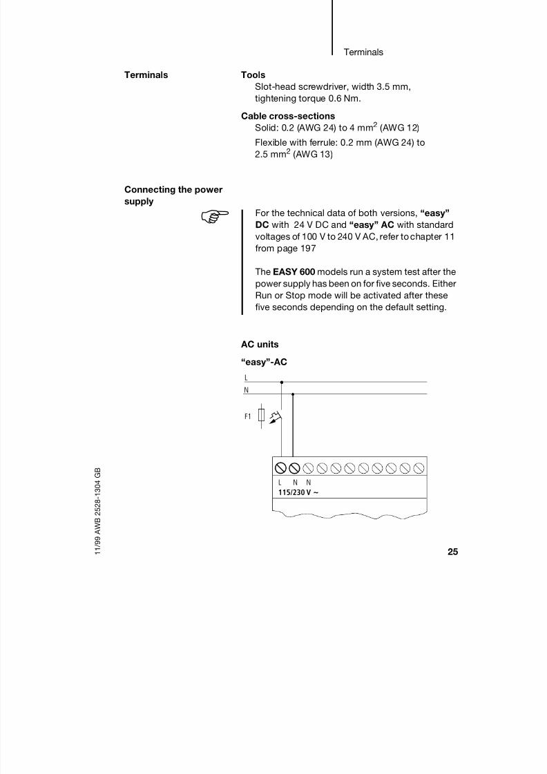
Terminals Tools
Slot-head screwdriver, width 3.5 mm,
tightening torque 0.6 Nm.Cable cross-sections
Solid: 0.2 (AWG 24) to 4 mm2 (AWG 12)
Flexible with ferrule: 0.2 mm (AWG 24) to
2.5 mm2 (AWG 13)
Connecting the power
supply
AC units
“easy”-AC
For the technical data of both versions, “easy”
DC with 24 V DC and “easy” AC with standard
voltages of 100 V to 240 V AC, refer tochapter 11
from page 197
The EASY 600 models run a system test after the
power supply has been on for five seconds. Either
Run or Stop mode will be activated after these
five seconds depending on the default setting.
NNL
N
F1
L
115/230 V ~

8/6/2019 Manual Easy 600
http://slidepdf.com/reader/full/manual-easy-600 29/229

8/6/2019 Manual Easy 600
http://slidepdf.com/reader/full/manual-easy-600 30/229
Connecting the power
supply
27 1 1 / 9 9 A W B 2 5 2 8 - 1 3 0 4 G B
DC units
“easy”-DC
“easy”-E
+24V 0V0V
L01-
F1
L01+
24 V DC
0V0V24V
L01-
F1
L01+
24 V
E+ E- R1 ... R12
“easy” DC is protected against polarity reversal.
To ensure that “easy” works correctly, ensure
that the polarity of each terminal is correct.

8/6/2019 Manual Easy 600
http://slidepdf.com/reader/full/manual-easy-600 31/229
Installation
28 1 1 / 9 9 A W B 2 5 2 8 - 1 3 0 4 G B
Cable protection
Both “easy” AC and DC versions require cable
protection (F1) rated for at least 1 A (slow).
Connecting the inputs “easy” inputs switch electronically. Once you haveconnected a contact via an input terminal, you can
reuse it as a relay contact in your “easy” circuit
diagram as often as you like.
Connect contacts such as push-button actuators or
switches to “easy” input terminals.
Connecting “easy” AC outputs
When “easy” is switched on for the first time, its
power supply circuit behaves like a capacitor.
Use an appropriate device for switching on the
power supply and do not use any reed relay
contacts or proximity switches.
+24 V
S1
0V Ι1
ΙΙ 1 1−
L
N
Caution
For “easy” AC, connect the inputs to the same
line as the power feed in accordance with VDE,
IEC, UL and CSA safety regulations. Otherwise,
“easy” will not detect the switching level or may
be damaged by overvoltage.

8/6/2019 Manual Easy 600
http://slidepdf.com/reader/full/manual-easy-600 32/229
Connecting the inputs
29 1 1 / 9 9 A W B 2 5 2 8 - 1 3 0 4 G B
“easy”-AC
“easy”-E
l1 I2 I7
L
N
L N N
230 V AC
L
N
> 1 A
R10R9R8R7R6R5R4R3R2R1E+ E- R11 R12 NNL
Input 115/230 V 115/230 V
8/6/2019 Manual Easy 600
http://slidepdf.com/reader/full/manual-easy-600 33/229
Installation
30 1 1 / 9 9 A W B 2 5 2 8 - 1 3 0 4 G B
Connect the inputs, for example, to push-button
actuators,
switches, relay or contactor contacts.
Input signal voltage range:
OFF signal: 0 V to 40 V
ON signal: 79 V to 264 V
Input current
R1 to R12
I1 to I6, I9 to I12: 0.5 mA/0.25 mAat 230 V/115 V
I7, I8: 6 mA/4 mA at
230 V/115 V
Cable lengths
Severe interference to cables can cause inputs to
signal 1 without a proper signal being applied.
Observe therefore the following maximum cable
lengths:R1 to R12,
I1 to I6, I9 to I12: 40 m without additional
circuit
I7, I8: 100 m without additional
circuits
For longer lengths connect a diode (e.g. 1N4007) for
1 A, min. 1000 V reverse voltage, to the easy input in
series. Ensure that the diode is pointing towards theinput as shown in the circuit diagram, otherwise
“easy” will not detect 1 status.

8/6/2019 Manual Easy 600
http://slidepdf.com/reader/full/manual-easy-600 34/229
Connecting the inputs
31 1 1 / 9 9 A W B 2 5 2 8 - 1 3 0 4 G B
“easy ”-AC
Neon bulbs with a maximum residual current of
2 mA/1 mA at 230 V/115 V may be connected at I7
and I8.
Two-wire proximity switches have a residual current
on 0. If this residual current is too high, the input of
“easy” may only detect the 1 signal.
Therefore use inputs I7, I8. An additional input circuit
is required if more inputs are used.
115/230 V AC
L
1 A
N
L N N I1
Always use neon bulbs that are operated with a
separate N connection.
Caution
Do not use reed relay contacts on I7, I8 . These
may burn or melt due to the high inrush current
of I7, I8.

8/6/2019 Manual Easy 600
http://slidepdf.com/reader/full/manual-easy-600 35/229
Installation
32 1 1 / 9 9 A W B 2 5 2 8 - 1 3 0 4 G B
Increasing the input current
The following input circuit can be used in order to
prevent interference and also when using two-wireproximity switches:
A resistor can be connected in series upstream of the
circuit shown in order to restrict the inrush current.
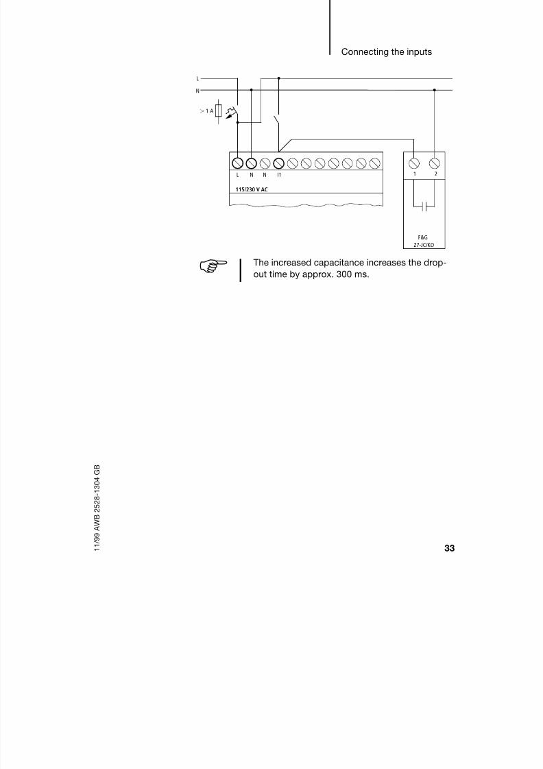
Complete devices for increasing the input current are
available, for example, from Felten & Guilleaume,
Type: Z7-JC/KO.
115/230 V AC
L
1 A
N
L N N I1
100 nF/275 V
When using a 100 nF capacitor the drop-off time
of the input increases by 80 (66.6) ms at 50
(60) Hz.
115/230 V AC
L
1 A
N
L N N I1
100 nF/275 V1 kΩ
8/6/2019 Manual Easy 600
http://slidepdf.com/reader/full/manual-easy-600 36/229
Connecting the inputs
33 1 1 / 9 9 A W B 2 5 2 8 - 1 3 0 4 G B
The increased capacitance increases the drop-
out time by approx. 300 ms.
115/230 V AC
L
1 A
N
L N N I1 1 2
F&G
Z7-JC/KO

8/6/2019 Manual Easy 600
http://slidepdf.com/reader/full/manual-easy-600 37/229
Installation
34 1 1 / 9 9 A W B 2 5 2 8 - 1 3 0 4 G B
Connecting “easy” DC inputs
Use input terminals I1 to I12 to connect push-button
actuators, switches or 3 or 4-wire proximityswitches. Given the high residual current, do not use
2-wire proximity switches.
Input signal voltage range:
OFF signal: 0 V to 5 V
ON signal: 15 V to 28.8 V
Input current
I1 to I6, I9 to I12: 3.3 mA at 24 V,
R1 to R12
I7, I8: 2.2 mA at 24 V
“easy ”-DC
L01+
L01-
24 V DC
0V+24V l1 I2 I7

8/6/2019 Manual Easy 600
http://slidepdf.com/reader/full/manual-easy-600 38/229

8/6/2019 Manual Easy 600
http://slidepdf.com/reader/full/manual-easy-600 39/229
Installation
36 1 1 / 9 9 A W B 2 5 2 8 - 1 3 0 4 G B
suppressor circuit for motors and valves. If loads
such as motors, solenoid valves or contactors are
operated with “easy” via the same power feed,switching may result in interference on the analog
input signals.
The following four circuits contain examples of
applications for analog value processing.
Setpoint potentiometers
Use a potentiometer with a resistance of 1 k, e.g.
1 k, 0.25 W.
Ensure that the reference potential is connected.
Connect the 0V of the power supply unit for the
different setpoint potentiometers and sensors
shown in the examples to the 0V of the “easy” power feed.

8/6/2019 Manual Easy 600
http://slidepdf.com/reader/full/manual-easy-600 40/229
Connecting the inputs
37 1 1 / 9 9 A W B 2 5 2 8 - 1 3 0 4 G B
Light intensity sensors
I7
L01-
L01+
24V 0V 0V
1.3 kO/0.25 W
1 kO/0.25 W
24 V
0V
0..10V
12V ~
L01+
L01-
0V +12V
24 V DC
0V 0V+24V I7

8/6/2019 Manual Easy 600
http://slidepdf.com/reader/full/manual-easy-600 41/229
Installation
38 1 1 / 9 9 A W B 2 5 2 8 - 1 3 0 4 G B
Temperature sensors
20 mA sensors
4 to 20 mA (0 to 20 mA) sensors can be connected
easily without any problem using an external 500
resistor.
Analog sensor
The following values apply:
4 mA = 0.2 V
10 mA = 4.8 V
20 mA = 9.5 V
(Based on V = R I = 478 10 mA 4.8 V).
24 V DC
L01
1 A
24 V
L01
0 V 0 V I7
500 Ω
4...20 mA

8/6/2019 Manual Easy 600
http://slidepdf.com/reader/full/manual-easy-600 42/229
Connecting the outputs
39 1 1 / 9 9 A W B 2 5 2 8 - 1 3 0 4 G B
Connecting the outputs The Q output terminals function inside “easy” as
isolated contacts.
In the “easy” circuit diagram the relay coils are
controlled via the corresponding output relays Q1 to
Q4 or Q1 to Q8 (Q6). You can use the signal states of
the output relays as make or break contacts in the
“easy” circuit diagram to provide additionalswitching conditions.
The relay or transistor outputs are used to switch
loads such as fluorescent tubes, filament bulbs,
contactors, relays or motors. Check the technical
thresholds and output data before installing such
devices (see chapter 11, from page 197.
Connecting relay
outputs
EASY 412-AC-..., EASY 412-DC-R...
Q11 2
0 V , N
8 A/B 16
L1, L2, L3 (115/230 V )+ 24 V
25.000
R L
24 V 8 A115 V 8 A230 V 8 A
2 A2 A2 A
1000 W
10 58 W
1 2 1 2 1 2 1 2
10 000 000
Q1 Q2 Q3 Q4

8/6/2019 Manual Easy 600
http://slidepdf.com/reader/full/manual-easy-600 43/229
Installation
40 1 1 / 9 9 A W B 2 5 2 8 - 1 3 0 4 G B
EASY 618/619-AC-RC(X)
EASY 618-AC-RE
Unlike the inputs, the outputs can be connected to
different lines.
0V ,N
8 A/B 16
L1, L2, L3 (115/230 V )
+ 24 V
25.000
R
24 V 8 A115V 8 A230V 8A
2 A2 A2 A
1000 W
10 58 W
1 2 2 2 2 2 21 1 1 1 1
10 000 000Q6Q5Q4Q3Q2Q1
0 V , N
F 8 A/B 16
L1, L2, L3 (115/230 V )+ 24 V
F 25.000
R
24 V 8 A115V 8 A230V 8 A
2 A2 A2 A
1000 W
10X
58 W
1 2 2 2 2 2 21 1 1 1 1
F 10 000 000
S6S5S4S3S2S1
Do not exceed the maximum voltage of
250 V AC on a relay contact.If the voltage exceeds this threshold, flashover
may occur at the contact, resulting in damage to
the device or a connected load.

8/6/2019 Manual Easy 600
http://slidepdf.com/reader/full/manual-easy-600 44/229
Connecting transistor
outputs
41 1 1 / 9 9 A W B 2 5 2 8 - 1 3 0 4 G B
Connecting transistor
outputs
EASY 412-DC-T...
EASY 620/621-DC-TC
0 V
R L
24 V 0.5 A
+24 V +24 V 0 V 0 V Q1 Q2 Q3 Q4
10 A
0.5 A
5 W/24 V
2.5 A+ 24 V20.4–28.8 V
Q Q Q Q
+ 24 V
R
5 W/24 V
0.5
0 V
+24 V 0 V Q1 Q2 Q3 Q4 Q5 Q6 Q7
f 2.5 A
(20.4–28.8 V )
F10 A
24 V 0.5 A
Q8Q Q

8/6/2019 Manual Easy 600
http://slidepdf.com/reader/full/manual-easy-600 45/229
Installation
42 1 1 / 9 9 A W B 2 5 2 8 - 1 3 0 4 G B
EASY 620-DC-TE
Parallel connection:
For increased power up to four outputs can be
connected in parallel. The output current will
increase in this case to a maximum of 2 A.
0 V
S1 S2 S3 S4 S5 S6 S7 S8 +24 V
f 2.5 A
F10 A
0V
+ 24 V
R
5 W/24 V
0.5
(20.4–28.8 V )
24 V 0.5 A
Q Q
CautionOutputs may only be connected in parallel within
a group (Q1 to Q4 or Q5 to Q8), such as Q1 and
Q3 or Q5, Q7 and Q8. Outputs connected in
parallel must be switched at the same time.
Caution
Please note the following when switching off
inductive loads.
Suppressed inductive loads cause less
interference in the entire electrical system. For
optimum suppression the suppressor circuits are
best connected directly to the inductive load.

8/6/2019 Manual Easy 600
http://slidepdf.com/reader/full/manual-easy-600 46/229
Connecting transistor
outputs
43 1 1 / 9 9 A W B 2 5 2 8 - 1 3 0 4 G B
If inductive loads are not provided with suppressor
circuits, only one inductive load should be switched
off at any one time so as to prevent the driver blocksfrom possibly overheating. If in the event of an
emergency stop the +24 V DC power supply is to be
switched off by means of a contact, and if this would
mean switching off more than one controlled output
with an inductive load, then you must provide
suppressor circuits for these loads (see the following
diagrams).
Behaviour in the event of short-circuits/overloadShould a short circuit or overload occur on a
transistor output, this output will switch off. The
output will switch on up to maximum temperature
after the cooling time has elapsed. This time
depends on the ambient temperature and the current
involved. If the fault condition persists, the output will
keep switching off and on until the fault is corrected
or until the power supply is switched off.
Scanning for short-circuit/overload see chapter 9,
from page 187.
0 V
Q..
+ 24 V
< 33 VU < Uemax z
0 V
Q..

8/6/2019 Manual Easy 600
http://slidepdf.com/reader/full/manual-easy-600 47/229
Installation
44 1 1 / 9 9 A W B 2 5 2 8 - 1 3 0 4 G B
Expanding inputs/
outputs
You can add expansion units to the following “easy”
models in order to increase the number of inputs and
outputs:
Local expansion
Local expansion units are connected directly next to
the basic unit.
Connect the “easy” expansion unit via the
“EASY-LINK” plug connector.
Expandable “easy”basic units
Expansion units
EASY 619-AC-RC(X)EASY 621-DC-TC(X)
EASY 618-AC-RE 12 inputs AC, 6 relayoutputs
EASY 620-DC-TE 12 inputs DC,8 transistor outputs
EASY619-...
EASY621-...
EASY6....-RE
EASY6....-TE
EASY200-EASY
EASY-LINK

8/6/2019 Manual Easy 600
http://slidepdf.com/reader/full/manual-easy-600 48/229
Expanding inputs/outputs
45 1 1 / 9 9 A W B 2 5 2 8 - 1 3 0 4 G B
Remote expansion
Remote expansion units can be installed and run up
to 30 m away from the basic unit.
Warning
The two-wire or multi-core cable between units
must have the necessary insulation voltage
required for the installation environment
concerned. In the event of a fault (earth leakage,
short-circuit) serious damage or injury to persons
may otherwise occur.
A cable such as NYM-0 with a rated operationalvoltage of Ue = 300/500 V AC is normally
sufficient.
E+E-
E+ E-
EASY619-...
EASY621-... EASY200-
EASY
EASY6.. RE/TE
Ue = 300/500 V
EASY...-AC-...E
Terminals “E+” and “E-” of the EASY 200-EASY
are protected against short-circuits and polarity
reversal. Functionality is only ensured if
“E+” is connected with “E+” and “E-” with “E-”.

8/6/2019 Manual Easy 600
http://slidepdf.com/reader/full/manual-easy-600 49/229
46 1 1 / 9 9 A W B 2 5 2 8 - 1 3 0 4 G B

8/6/2019 Manual Easy 600
http://slidepdf.com/reader/full/manual-easy-600 50/229
47 1 1 / 9 9 A W B 2 5 2 8 - 1 3 0 4 G B
4 Commissioning
Switching on Before switching on “easy”, check that you have
connected the power supply terminals and inputs
correctly:
24 V DC version:
Terminal +24 V: Voltage +24 V
Terminal 0 V: Voltage 0 V
Terminals I1 to I12, R1 to R12:
Activation via +24 V
230 V AC version
Terminal L: L conductor
Terminal N: Neutral N
Terminals I1 to I12, R1 to R12:
Activation via L conductor
If you have already integrated “easy” into a system,
secure any parts of the system connected to the
working area to prevent access and ensure that no-one can be injured if, for example, motors start up
unexpectedly.
Setting the menu
language
When you switch on “easy” for the first time, you will
be asked to select the menu language.
Use thecursor buttons Í or
Úto select a language
GB English
D German
F French
E Spanish
I Italian
ENGLISH
GB D F E I

8/6/2019 Manual Easy 600
http://slidepdf.com/reader/full/manual-easy-600 51/229
Commissioning
48 1 1 / 9 9 A W B 2 5 2 8 - 1 3 0 4 G B
EASY 600 also supports the following languages:
Portuguese
Dutch
Swedish
Polish
Turkish
Press OK to confirm your choice or press ESC to
exit the menu.
“easy” will then switch to the status display.
“easy” operating
modes
“easy” has two operating modes - Run and Stop.
In Run mode “easy” continuously processes a stored
circuit diagram until you select Stop or disconnect
the power. The circuit diagram, parameters and the
“easy” settings are retained in the event of a power
failure. All you will have to do is reset the real-time
clock after the back-up time has elapsed. Circuit
diagram entry is only possible in Stop mode.
You can change the language setting at a later
date, if you wish, see chapter 7, page 139.
If you do not set the language, “easy” will display
this menu and wait for you to select a language
every time you switch on.
CautionIn Run mode “easy” will immediately run the
saved circuit diagram in the unit when the power
supply is switched on. This will happen unless
Stop mode was set as startup mode. In Run
mode outputs are activated according to the
switch logic involved.

8/6/2019 Manual Easy 600
http://slidepdf.com/reader/full/manual-easy-600 52/229
Creating your first circuit
diagram
49 1 1 / 9 9 A W B 2 5 2 8 - 1 3 0 4 G B
In the case of “easy” models with an LCD display, a
circuit diagram on a fitted memory card is not run
automatically. The circuit diagram must first betransferred from the memory card to the “easy” unit.
In Run mode “easy”-X models load the circuit
diagram on the memory card automatically and run it
immediately.
Creating your first
circuit diagram
The following small circuit diagram takes you step by
step through wiring up your first “easy” circuit
diagram. In this way you will learn all the rules,
quickly enabling you to use “easy” for your own
projects.
As with conventional wiring, you use contacts and
relays in the “easy” circuit diagram. With “easy”,
however, you no longer have to connect up
components individually. At the push of a few
buttons, the “easy” circuit diagram produces all the
wiring. All you have to do is then connect any
8/6/2019 Manual Easy 600
http://slidepdf.com/reader/full/manual-easy-600 53/229
Commissioning
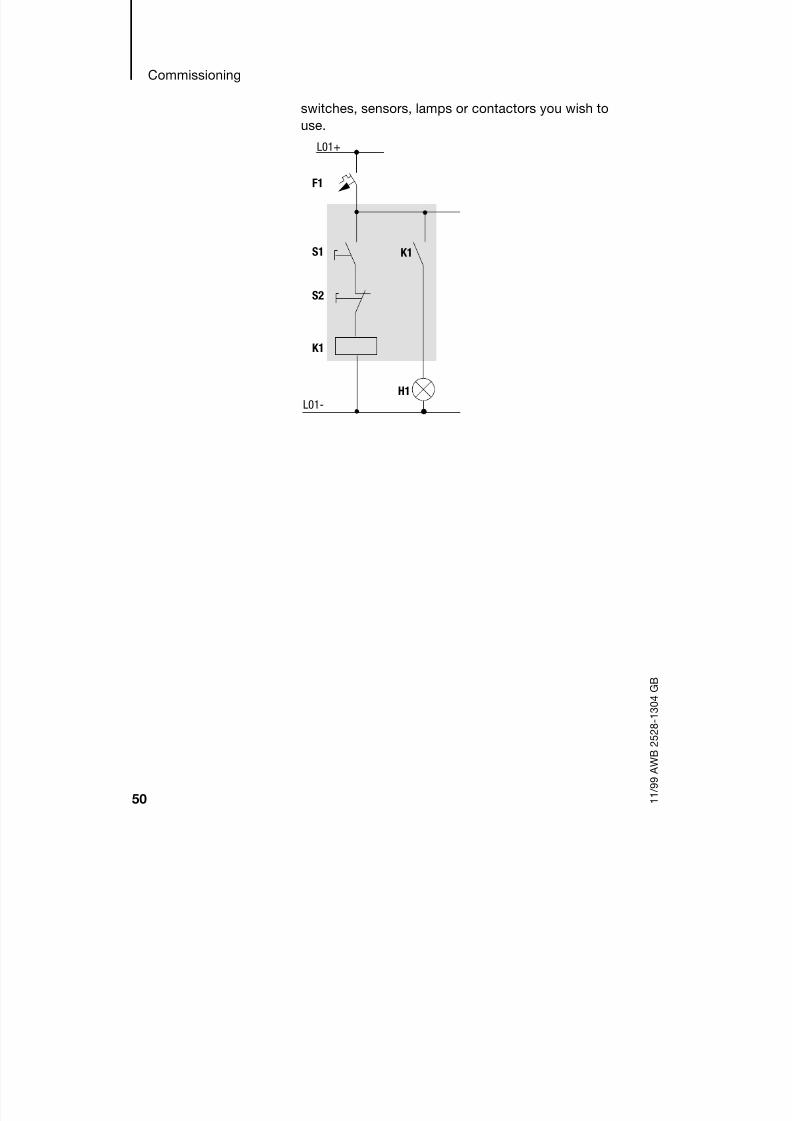
50 1 1 / 9 9 A W B 2 5 2 8 - 1 3 0 4 G B
switches, sensors, lamps or contactors you wish to
use.
H1
L01-
S1
S2
L01+
F1
K1
K1

8/6/2019 Manual Easy 600
http://slidepdf.com/reader/full/manual-easy-600 54/229
Creating your first circuit
diagram
51 1 1 / 9 9 A W B 2 5 2 8 - 1 3 0 4 G B
In the following example, “easy” carries out all the
wiring and performs the tasks of the circuit diagram
highlighted above.
Starting point: the status display
When you switch on “easy”, it opens the statusdisplay immediately to show the switching state of
the inputs and outputs. It also indicates whether
“easy” is already running a circuit diagram.
1 2
Q1
H1
L01-
S1 S2
L01+
L01-
F1
+24V 0V I1 I2

8/6/2019 Manual Easy 600
http://slidepdf.com/reader/full/manual-easy-600 55/229
Commissioning
52 1 1 / 9 9 A W B 2 5 2 8 - 1 3 0 4 G B
Press OK to switch to the main menu.
You can then press OK to move forward to the next
menu level or ESC to go back one level.
In this case “easy” must be in Stop mode
Press 2 OK to enter the circuit diagram display
via menu points “PROGRAM...” -> PROGRAM.
This is where you will create the circuit diagram.
Circuit diagram display
The circuit diagram display is
currently empty. The cursor is
flashing at the top left, which is
where you will start to create
your diagram.
The examples were written without the use of
expansion units. If an expansion unit is
connected, the status display will first show thestatus of the basic unit and then the status of the
expansion unit before showing the first selection
menu.
EASY 412: EASY 600:
I12345678######## MO
#### 13:24Q1234 STOP
............
MO 02:00........STOP
OK has two other functions:
Press OK to save modified settings.
In the circuit diagram, you can also press OK
to insert and modify contacts and relay coils.
ê

8/6/2019 Manual Easy 600
http://slidepdf.com/reader/full/manual-easy-600 56/229
Creating your first circuit
diagram
53 1 1 / 9 9 A W B 2 5 2 8 - 1 3 0 4 G B
Move the cursor using the
cursor buttons ÍÚ ú í across
the hidden grid lines
The first three double columns
are the contact fields and the right-hand columns
form the coil field. Each line is a circuit connection.
“easy” will add the first contact automatically.
Now try to wire up the
following “easy” circuit
diagram.
Switches S1 and S2 are at the
input I1 and I2 are the
contacts for the input terminals.
Relay K1 is represented by the relay coil ÄQ1. The
symbol “Ä” identifies the coil's function, in this case
a relay coil acting as a contactor. Q1 is one of up to
eight “easy” output relays.
From the first contact to the output coil
With “easy”, you work from the input to the output.
The first input contact is I1.
Press OK.
“easy” inserts the first contact
I1 at the cursor position.
The “I” flashes and can be
changed, for example, to a “P”
for a button input using the cursor buttons Í or Ú.
However, nothing needs to be changed at this point,
so...
...Press 2 OK to move the cursor across the 1
to the next contact field.
êê êê êê êêêêê êê êê êêêêê êê êê êêêêê êê êê êêê
↑→
↓
←
I1-I2----ÄQ1
I1 êê êê êêê

8/6/2019 Manual Easy 600
http://slidepdf.com/reader/full/manual-easy-600 57/229
Commissioning
54 1 1 / 9 9 A W B 2 5 2 8 - 1 3 0 4 G B
You could also move the cursor to the next contact
field using the cursor button í.
Press OK.
Again, “easy” creates a contact
I1 at the cursor position.
Change the contact number to
I2 so that break contact S2 can
be connected to input terminal
I2.
Press OK so that the cursor jumps to the next
position and press cursor button Í or Ú to
change the number to 2.
Press OK to move the cursor
to the third contact field
You do not need a third relay
contact, so you can now wirethe contacts directly to the coil
field.
Wiring
“easy” displays a small arrow when creating the
circuit diagram.
Press ALT to activate the arrow and the cursorbuttons ÍÚ ú í to move it.
I1 I1 êê êêê
Press DEL to delete a contact at the cursor
position.
I1-I2 Â
ALT also has two other functions:
From the left contact field, press ALT to insert
a new, empty circuit connection.
Press ALT to set the contact currently under
the cursor to either a make or break contact.

8/6/2019 Manual Easy 600
http://slidepdf.com/reader/full/manual-easy-600 58/229
Creating your first circuit
diagram
55 1 1 / 9 9 A W B 2 5 2 8 - 1 3 0 4 G B
The wiring arrow works
between contacts and relays.
When you move the arrow ontoa contact or relay coil, it
changes back to the cursor and
can be reactivated with ALT if
required.
Press ALT to “wire” the cursor from I2 through to
the coil field.
The cursor changes into a
flashing wiring arrow and
automatically jumps to the next
possible wiring position.
Press the cursor button í.Contact I2 will be connected
up to the coil field.
Press the cursor button í again.
The cursor will move to the coil field.
Press Press OK.
“easy” will insert relay coil Q1.
The specified coil function “Ä”
and the output relay Q1 are
correct and do not have to be
changed.
êê êê êêê
êê êêê
↑→
↓
←l
“easy” automatically wires adjacent contacts in a
circuit connection up to the coil.
I1-I2l êê êê êê êêêêê êê êê êêêêê êê êê êêê
Use the DEL button to delete a wiring at the
cursor or arrow position. Where connections
intersect, the vertical connections are deleted
first, then, if you press DEL again, the horizontal
connections are deleted.
I1-I2----ÄQ1

8/6/2019 Manual Easy 600
http://slidepdf.com/reader/full/manual-easy-600 59/229
Commissioning
56 1 1 / 9 9 A W B 2 5 2 8 - 1 3 0 4 G B
Your first working “easy” circuit
diagram now looks like this:
Press ESC to leave the circuitdiagram display. The diagram
will be automatically saved.
Once you have connected buttons S1 and S2, you
can test your circuit diagram straight away.
Testing the circuit diagram
Switch to the main menu
and select the RUN menu
option.
Toggle between RUN and STOP
to set the operating mode
required.
“easy” is in Run mode if the STOP menu option is
displayed.
The Status display shows the current mode and the
switching states of the inputs and outputs.
Change to the Status display and press push-
button actuator S1.
The boxes for inputs I1 and I2 are activated and relay
Q1 picks up.
I1-I2----ÄQ1
PROGRAM...RUNPARAMETERSET CLOCK..
Menu points that toggle between two functions
always show the next possible setting.
EASY 412: EASY 600:
I12345678ââ###### MOâ### 12:50
Q1234 RUN
12..........
MO 02:001........RUN

8/6/2019 Manual Easy 600
http://slidepdf.com/reader/full/manual-easy-600 60/229
Creating your first circuit
diagram
57 1 1 / 9 9 A W B 2 5 2 8 - 1 3 0 4 G B
Power flow display
“easy” allows you to check circuit connections in
Run mode. This means that you can check yourcircuit diagram via the built-in power flow display
while it is being processed by “easy”.
Change to the Circuit
diagram display and press
push-button actuator S1.
The relay picks up and “easy”
shows the flow of current.
Press push-button actuator
S2, that has been connected
as a break contact.
The circuit connection is
interrupted and relay Q1 drops
out.
Press ESC to return to the Status display.
Deleting a circuit diagram
Switch “easy” to Stop mode.
The RUN option is displayed.
I1I1I1I1-I2----ÄQ1
I1----I2----ÄQ1
A circuit diagram does not have to be completedbefore you can test parts of it with “easy”.
“easy” simply ignores any incomplete wiring that
is not yet working and only uses the finished
wiring.
“easy” must be in Stop mode in order to extend,
delete or modify the circuit diagram.

8/6/2019 Manual Easy 600
http://slidepdf.com/reader/full/manual-easy-600 61/229
58 1 1 / 9 9 A W B 2 5 2 8 - 1 3 0 4 G B
Use “PROGRAM...” to switch from the main
menu to the next menu level.
Select “DELETE PROG”
“easy” will display the prompt
“DELETE?”.
Press OK to delete the
program or ESC to cancel.
Press ESC to return to the Status display.
Fast circuit diagram entry
You can create a circuit diagram in several ways. The
first option is to enter the elements in the circuit
diagram and then wire all the elements together. The
other option is to use the enhanced operator
guidance of “easy” and create the circuit diagram in
one go, from the first contact through to the last coil.
If you use the first option, you will have to selectsome of the elements in order to create and connect
up your circuit diagram.
The second, faster option is what you learned in the
example. In this case you create the entire circuit
connection from left to right.
PROGRAMDELETE PROG

8/6/2019 Manual Easy 600
http://slidepdf.com/reader/full/manual-easy-600 62/229
59 1 1 / 9 9 A W B 2 5 2 8 - 1 3 0 4 G B
5 Drawing a Circuit Diagram with “easy”
By working through the example in chapter 4 you
should now have gained an initial impression of just
how simple it is to create a circuit diagram in “easy”.
This chapter describes the full range of “easy”
functions and provides further examples of how to
use “easy”.
Operation of “easy” Buttons for drawing circuit diagrams
Delete circuit connection, contact, relay or
empty line in the circuit diagram
Toggle between break and make contact
Connect contacts and relays
Add circuit connections
ÍÚ
ú í
Change value
Move cursor up and downChange position
Move cursor to left and right
Cursor buttons set as P buttons:
úí
Input P1,
Input P3,ÍÚ
Input P2
Input P4
Undo settings from previous OK
Exit current display
Change, add contact/relay
Save setting

8/6/2019 Manual Easy 600
http://slidepdf.com/reader/full/manual-easy-600 63/229
Drawing a Circuit Diagram
with “easy”
60 1 1 / 9 9 A W B 2 5 2 8 - 1 3 0 4 G B
Operation of “easy”
The cursor buttons in the “easy” circuit diagram
perform three functions. The current mode isindicated by the appearance of the flashing cursor.
Move
Enter
Connect
In Move mode you can useÍÚ ú í to move the
cursor around the circuit diagram in order to
select a circuit connection, contact or relaycoil.
Use OK to switch to Enter mode so that you
can enter or change a value at the current
cursor position. If you press ESC in Enter
mode, “easy” will undo the most recent changes.
Press ALT to switch to Connect mode for
wiring contacts and relays. Press ALT again to
return to Move.
Press ESC to leave the circuit diagram and
parameter display.
Opening the parameter display
If you specify the contact of a relay type in Enter
mode, “easy” automatically switches from the
contact number to the parameter display when you
press OK.
Press í to switch to the next contact or coil field
without entering any parameters.
â
I1
l
“easy” performs many of these cursor
movements automatically. For example, “easy”
switches the cursor to Move mode if no further
entries or connections are possible at the
selected cursor position.

8/6/2019 Manual Easy 600
http://slidepdf.com/reader/full/manual-easy-600 64/229
Operation of “easy”
61 1 1 / 9 9 A W B 2 5 2 8 - 1 3 0 4 G B
Contacts
Contacts are used to modify the flow of current in the
“easy” circuit diagram. Contacts such as makecontacts carry a 1 signal when closed and 0 when
open. Every contact in the “easy” circuit diagram can
be defined as either a make contact or a break
contact.
“easy” works with different contacts, which can be
used in any order in the contact fields of the circuit
diagram.
Contact “easy” representation
Make contactOpen in the rest state
I,Q,M,A,Ö,C,T,P,D,S,:,R
Break contactClosed in the rest state
i,q,m,a,ö,c,t,p,,,
Contact type Makecontact
Breakcontact
EASY 412 EASY 600 Page
“easy” input terminal I i I1...I8 I1...I12 page 65
0 signal I13
Expansion status I14 page 191
Short circuit/overload I16 I15...I16 page 187
P button contact (cursor buttons) P p P1...P4 P1...P4 page 70
“easy” output Q q Q1...Q4 Q1...Q8 page 65
Marker relay contact M m M1...M16 M1...M16 page 73
Counter relay contact C c C1...C8 C1...C8 page 90
Timing relay contact T t T1...T8 T1...T8 page 84
Time switch contact Ö ö Ö1...Ö4 Ö1...Ö4 page 93
Analog comparator relay A a A1...A8 A1...A8 page 98
Text marker relay D – D1...D8 page 103
“easy” output relay expansion or “S”
auxiliary marker
S – S1...S8 page 73
Jump label : – – :1...:8 page 105
Expansion input terminal R – R1...R12 page 65
Short circuit/overload with expansion R – R15...R16 page 187

8/6/2019 Manual Easy 600
http://slidepdf.com/reader/full/manual-easy-600 65/229

8/6/2019 Manual Easy 600
http://slidepdf.com/reader/full/manual-easy-600 66/229
Operation of “easy”
63 1 1 / 9 9 A W B 2 5 2 8 - 1 3 0 4 G B
Insert relay contacts in the three contact fields.
The first contact field is automatically connected
to the voltage.Insert the relay coil to be controlled together with
its function and designation in the coil field.
Every line in the circuit diagram forms a circuit
connection. EASY 412 and EASY 600 permit the
connection of 41 and 121 circuit connections/
current paths respectively.
Connections are used to produce the electricalcontact between relay contacts and the coils.
Connections can be created across several
circuit connections. Each point of intersection is
a connection.
Contact fields Coil field
Circuit
connections/
Current paths
I1-I2uT1-ÄQ1Q1-Ö1kêê êêêêê êê êê êêêêê êê êê êêê
Connections
The circuit diagram display performs two
functions:
In Stop mode it is used to edit the circuit
diagram
In Run mode it is used to check the circuit
diagram using the Power flow display

8/6/2019 Manual Easy 600
http://slidepdf.com/reader/full/manual-easy-600 67/229
Drawing a Circuit Diagram
with “easy”
64 1 1 / 9 9 A W B 2 5 2 8 - 1 3 0 4 G B
Saving and loading circuit diagrams
There are two ways of saving circuit diagrams in
“easy” externally:
By saving to a memory card
By saving to a PC running EASY-SOFT.
Once they have been saved, programs can be
reloaded into “easy”, edited and run.
All circuit diagram data is saved in “easy”. In the
event of a power failure the data will be retained until
the next time it is overwritten or deleted.
Memory card
Each memory card contains a circuit diagram which
is inserted into the “easy” interface.
The way the memory card works and a description of
how to transfer a program to the card is given in
chapter 6, from page 126.
EASY-SOFTEASY-SOFT is an optional PC program with which
you can create, store, test (simulate) and manage
“easy” circuit diagrams.
Completed circuit diagrams are transferred between
your PC and “easy” via the connecting cable. Once
you have transferred a circuit diagram, simply run
“easy” straight from your PC.
Details on the program and transferring circuitdiagrams are given in chapter 6, from page 130.
Working with contacts
and relays
In “easy” circuit diagrams, the switches, buttons and
relays of conventional circuit diagrams are
connected up using input contacts and relay coils.

8/6/2019 Manual Easy 600
http://slidepdf.com/reader/full/manual-easy-600 68/229
Working with contacts and
relays
65 1 1 / 9 9 A W B 2 5 2 8 - 1 3 0 4 G B
First specify which input and output terminals you
wish to use in your circuit.
Depending on the model concerned “easy” has 8 or
12 input terminals and 4, 6 or 8 outputs. The signal
states at the input terminals are recorded in the
circuit diagram using input contacts I1 to I12 or R1 to
R12. In the circuit diagram, the outputs are switchedusing output relays Q1 to Q8 and S1 to S8.
Entering or modifying the contact or relay
Conventional circuit “easy” circuit diagram
Connecting up “easy”
Connect S1 to “easy” input terminal I1Connect S2 to “easy” input terminal I3Connect load H1 to “easy” output Q4
S1 or S2 switches on H1.“easy” circuit diagram
H1
S1
K1
K1S2
I2u------ÄQ4I3k
Define a contact in “easy” via
its name and number.I2
Contact number
Contact name
A relay is defined by its coil
function, name and number.ÄQ4
Relay number
Relay name
Coil function
8/6/2019 Manual Easy 600
http://slidepdf.com/reader/full/manual-easy-600 69/229
Drawing a Circuit Diagram
with “easy”
66 1 1 / 9 9 A W B 2 5 2 8 - 1 3 0 4 G B
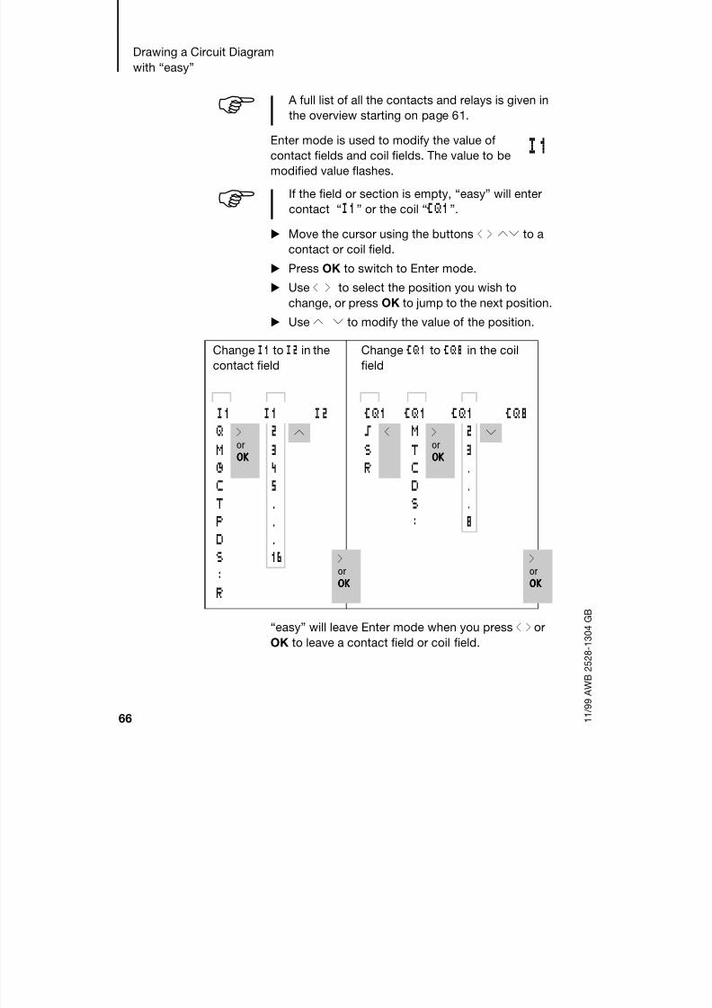
Enter mode is used to modify the value of
contact fields and coil fields. The value to be
modified value flashes.
Move the cursor using the buttons ú í ÍÚ to a
contact or coil field.
Press OK to switch to Enter mode.
Use ú í to select the position you wish to
change, or press OK to jump to the next position.
Use Í Ú to modify the value of the position.
“easy” will leave Enter mode when you press ú í or
OK to leave a contact field or coil field.
A full list of all the contacts and relays is given in
the overview starting on page 61.
I1
If the field or section is empty, “easy” will enter
contact “I1” or the coil “ÄQ1”.
Change I1 to I2 in the
contact field
Change ÄQ1 to ÄQ8 in the coil
field
I1 I1 I2 ÄQ1 ÄQ1 ÄQ1 ÄQ8Q í
orOOOOKKKK
2 Í ä ú M íorOOOOKKKK
2 ÚM 3 S T 3Ö 4 R C .C 5 D .T . S .P . : 8
D .S 16 í
orOOOOKKKK
íorOOOOKKKK
:R

8/6/2019 Manual Easy 600
http://slidepdf.com/reader/full/manual-easy-600 70/229
Working with contacts and
relays
67 1 1 / 9 9 A W B 2 5 2 8 - 1 3 0 4 G B
Deleting contacts and relay coils
Move the cursor using the buttons ú í ÍÚ to a
contact or coil field. Press DEL.
The contact or the relay coil will be deleted, together
with any connections.
Changing make contacts into break contacts
Every relay contact in the “easy” circuit diagram can
be defined as either a make contact or a break
contact.
Switch to Enter mode and move the cursor over
the contact name.
Press ALT. The make contact will change to a
break contact.
Press 2 OK to confirm the change.
Creating and modifying connections
Relay contacts and relay coils are connected
in Connect mode using the diagonal wiringarrow which is made available in this mode.
Use ú í ÍÚ to move the cursor onto the contact
field or coil field from which you wish to create a
connection.
I2u------ÄQ4
I3k
I2u------ÄQ4
i3k
I2u------ÄQ4
i3kê2
l
Do not position the cursor on the first contact
field. At this position the ALT button has a
different function (Insert circuit connection).

8/6/2019 Manual Easy 600
http://slidepdf.com/reader/full/manual-easy-600 71/229

8/6/2019 Manual Easy 600
http://slidepdf.com/reader/full/manual-easy-600 72/229
Working with contacts and
relays
69 1 1 / 9 9 A W B 2 5 2 8 - 1 3 0 4 G B
Close the delete operation with ALT or by moving the
cursor to a contact or coil field.
Inserting and deleting a circuit connection
The “easy” circuit diagram shows four of the 41 or
121 circuit connections in the display at the same
time. “easy” automatically scrolls up or down the
display to show hidden circuit connections – even
empty ones – if you move the cursor past the top or
bottom of the display.
A new circuit connection is added below the last
connection or inserted above the cursor position:
Position the cursor on the
first contact field of the
empty circuit connection.
Press ALT.
The existing circuit connectionwith all its additional
connections, will be “shifted”
down. The cursor will then be
positioned directly in the new
circuit connection.
I2u------ÄQ4I3k
I2u------ÄQ4Â nI3k

8/6/2019 Manual Easy 600
http://slidepdf.com/reader/full/manual-easy-600 73/229
Drawing a Circuit Diagram
with “easy”
70 1 1 / 9 9 A W B 2 5 2 8 - 1 3 0 4 G B
Deleting a circuit connection
“easy” will only remove empty circuit connections,
i.e. those without contacts or coils. Delete all the contacts and relay coils from the
circuit connection.
Position the cursor on the first contact field of the
empty circuit connection.
Press DEL.
The subsequent circuit connection(s) will be “pulled
up” and any existing links between circuit
connections will be retained.
Switching via the cursor buttons
With “easy”, you can also use the four cursor buttons
as hard-wired inputs in the circuit diagram.
The buttons are wired as contacts P1
to P4 in the circuit diagram. The Pbuttons can be activated and
deactivated in the System menu.
The P buttons can also be used for
testing circuits or manual operation. These button
functions are also useful for servicing and
commissioning purposes.
P1
P2
P3
P4

8/6/2019 Manual Easy 600
http://slidepdf.com/reader/full/manual-easy-600 74/229
Working with contacts and
relays
71 1 1 / 9 9 A W B 2 5 2 8 - 1 3 0 4 G B
Example 1
A lamp at output relay Q1 is
switched on and off via inputs I1and I2 or using cursor buttons
ÍÚ.
Example 2
Terminal “I1” is used to control
output relay “Q1”. Terminal I5
switches to Cursor button mode
and deactivates circuit
connection I1 via m1.
The Status menu display shows whether the P
buttons are used in the circuit diagram.
P Button function wired and active
P2 Button function wired, active and
P2 button Í pressed
P- Button function wired, not active
Empty box: P buttons not used
I1u------SQ1P2kI2u------RQ1P4k
I5-------ÄM1I1-m1u---ÄQ1P1-M1k
The P buttons are only recognised as switch
contacts in the Status menu, and not in the Power
flow display.
I12345678 P2
######## MO#### 01:00
Q1234 STOP
............
P2MO 02:00........STOP

8/6/2019 Manual Easy 600
http://slidepdf.com/reader/full/manual-easy-600 75/229
Drawing a Circuit Diagram
with “easy”
72 1 1 / 9 9 A W B 2 5 2 8 - 1 3 0 4 G B
Checking the circuit diagram
“easy” contains a built-in measuring device enabling
you to monitor the switching states of contacts andrelay coils during operation.
Complete the small parallel
connection and switch
“easy” to Run mode via the
main menu.
Return to the circuit diagram
display.
You are now unable to edit the circuit diagram.
The circuit diagram display performs two functions
depending on the mode:
STOP: Create circuit diagramRUN: Power flow display
Switch on I3.
In the power flow display,
energised connections are
thicker than non-energized
connections.
You can follow a current-carrying connection acrossall circuit connections by scrolling the display up and
down.
I2---u---ÄQ4I3---k
If you switch to the circuit diagram display and
are unable to modify a circuit diagram, first check
whether “easy” is in Stop mode.
I2---U---ÄQ4I3---k
The power flow display will not show signal
fluctuations in the millisecond range. This is due to
the inherent delay factor of LCD displays.

8/6/2019 Manual Easy 600
http://slidepdf.com/reader/full/manual-easy-600 76/229
Working with contacts and
relays
73 1 1 / 9 9 A W B 2 5 2 8 - 1 3 0 4 G B
Coil functions
You can set the coil function to determine the
switching behaviour of relay coils. The following coilfunctions are available for relays Q, M, S, D, “:”
Marker relay M is used as a “flag”. The S relay can be
used as the output of an expansion unit or as a
marker if no expansion unit is connected. The only
difference between them and the output relay Q is
that they have no output terminals.
Circuit diagramsymbol
“easy” symbol
Coil function Example
Ä Contactorfunction
ÄQ1,ÄD2,ÄS4,Ä:1ÄM7
ä Impulse relay
function
äQ3,äM4,
äD8,äS7
S Set (latching) SQ8,SM2,SD3,SS4
R Reset(unlatching)
RQ4,RM5,RD7,RS3
The functions of timer and counter relays are
explained in the relevant relay description.
The coil function Ä (contactor) should only beused once for each coil. Otherwise the last coil in
the circuit diagram will determine the status of the
relay.

8/6/2019 Manual Easy 600
http://slidepdf.com/reader/full/manual-easy-600 77/229
Drawing a Circuit Diagram
with “easy”
74 1 1 / 9 9 A W B 2 5 2 8 - 1 3 0 4 G B
To ensure an overview of all relay states only assign
the same coil function once to a relay (ä, S, R).
However, retentive coil functions such asä
, S, R canbe used several times if required by the circuit
diagram logic.
Exception: The coil function can be used properly
several times when using jumps to structure the
circuit diagram.
Rules for wiring relay coils
Use the contactor or “impulse relay” function once
only for each relay coil.
Only use the “latch” (S) and “unlatch” (R) functions
once to control each relay in order to ensure greater
clarity in the circuit diagram.
Relays with contactor function
The output signal follows
immediately after the input signal,
and the relay acts as a contactor.
Signal diagram:
Representation in “easy”
Q output relay: ÄQ1...ÄQ8(depending on type)
M marker relay: ÄM1...ÄM16Text display relays D: ÄD1...ÄD8 (EASY 600)
S relays: ÄS1...ÄS8 (EASY 600)
Jumps: Ä:1...Ä:8 (EASY 600)
on
on

8/6/2019 Manual Easy 600
http://slidepdf.com/reader/full/manual-easy-600 78/229
Working with contacts and
relays
75 1 1 / 9 9 A W B 2 5 2 8 - 1 3 0 4 G B
Impulse relay
The relay coil switches whenever the
input signal changes from 0 to 1. Therelay behaves like an impulse relay.
Signal diagram:
Representation in “easy”
Q output relay: ÄQ1...ÄQ8(depending on type)
M marker relay: ÄM1...ÄM16Text display relay D: ÄD1...ÄD8 (EASY600)
S relay: ÄS1...ÄS8 (EASY 600)
on
on
A coil is automatically switched off if the powerfails and if “easy” is in Stop mode. Exception:
Retentive coils retain signal 1 (see chapter 8,
page 156

8/6/2019 Manual Easy 600
http://slidepdf.com/reader/full/manual-easy-600 79/229

8/6/2019 Manual Easy 600
http://slidepdf.com/reader/full/manual-easy-600 80/229
Function relay types
77 1 1 / 9 9 A W B 2 5 2 8 - 1 3 0 4 G B
If both coils are triggered at the
same time, priority is given to
the coil further down in thecircuit diagram. This is shown in
the above signal diagram in
section “B”.
Function relay types The function relays are used to simulate some of the
devices used in conventional control systems.
“easy” provides the following function relay types:
I1-I2----SQ1......I2-------RQ1
A latched relay is automatically switched off if the
power fails or if the device is in Stop mode.
Exception: Retentive coils retain signal 1 (see
chapter 8,page 156 ).
Circuit diagram symbol Function relays
Timing relay, on-delayedTiming relay, on-delayed with randomswitching
Timing relay, off-delayedTiming relay, off-delayed with randomswitching
Timing relay, single pulseTiming relay, flashing
Counter relay, up/down counter
Time switch, weekday/time(only in “easy” models with clock)
Analog comparator relay(only in “easy” 24 V DC models)
Text (only EASY 600)
D C R

8/6/2019 Manual Easy 600
http://slidepdf.com/reader/full/manual-easy-600 81/229
Drawing a Circuit Diagram
with “easy”
78 1 1 / 9 9 A W B 2 5 2 8 - 1 3 0 4 G B
A function relay is started via its relay coil or by
evaluating a parameter. It switches the contact of the
function relay according to its function and the setparameters.
In timing and counter relays, it is also possible to
change the switching behaviour via the coil function.
Example with timing and counter relays
A warning light flashes when the counter reaches 10.
In this example, both relays C1 and T1 are wired.
Current actual values are deleted if the power
supply is switched off or if “easy” is switched to
Stop mode.
Exception: Retentive coils retain signal (see
chapter 8, page 156).
Hard-wiring with relays
L01–
P1
P1
K1T
K1T
C R
H1
S1 S2
L01+
2sCounter
Value 10

8/6/2019 Manual Easy 600
http://slidepdf.com/reader/full/manual-easy-600 82/229

8/6/2019 Manual Easy 600
http://slidepdf.com/reader/full/manual-easy-600 83/229
Drawing a Circuit Diagram
with “easy”
80 1 1 / 9 9 A W B 2 5 2 8 - 1 3 0 4 G B

8/6/2019 Manual Easy 600
http://slidepdf.com/reader/full/manual-easy-600 84/229

8/6/2019 Manual Easy 600
http://slidepdf.com/reader/full/manual-easy-600 85/229
Drawing a Circuit Diagram
with “easy”
82 1 1 / 9 9 A W B 2 5 2 8 - 1 3 0 4 G B
Enter the circuit diagram up
to “C1” in the third circuit
connection.C1 is the contact of counter
relay 1.
Move the cursor onto the 1 in C1 and press OK.
The parameter set for the counter is displayed.
Change the counter setpoint
to 10:
Use ú í to move the cursor
onto the tens digit.
Use ÍÚ to modify the value
of the digit.
Press OK to save the value and ESC to return to
the circuit diagram.
Enter the circuit diagram up
to contact “T1” of the timing
relay. Set the parameters for
T1.
The timing relay works like a
flasher/blink relay. The “easy”
symbol for the flasher/blink relay is “Ü”. It is set at the
top left of the parameter display.
Complete the circuit diagram.
Test the circuit diagram using the power flow
display.
Switch “easy” to Run mode and return to thecircuit diagram.
I5-------CC1I6-------RC1C1
If the cursor is on the contact number, “easy” will
call up the parameter display when you press OK.
f0010gsDIR n
Ä sCNT d C1Ä yRES b +
“easy” has specific parameter displays for
function relays. The meaning of these parameters
is explained under each relay type.
Ü w gS n02.00nÄ sTRG dT1
yRES b +

8/6/2019 Manual Easy 600
http://slidepdf.com/reader/full/manual-easy-600 86/229
Function relay types
83 1 1 / 9 9 A W B 2 5 2 8 - 1 3 0 4 G B
Each set parameter can be displayed using the
power flow display for the circuit diagram.
Move the cursor onto C1 and press OK.
The parameter set for the
counter is displayed with actual
and setpoint values.
Switch I5. The actual value
changes.
The coil terminal CNT is
activated for as long as youpress push-button actuator S1.
This is represented in the “easy”
parameter display.
If the actual and setpoint values
are the same, the timing relay switches the warning
light on and off every 2 seconds.
Doubling the flashing frequency:
Select T1 in the power flow
display and change the
setpoint time to 01.00.
When you press OK, the
warning light will flash at twice
the frequency.
You can also modify parameter settings via the
PARAMETER menu option.
f0010g0000sDIR n
Ä sCNT d C1Ä yRES b +
f0010g0002sDIR nÄ ssssCNT d C1Ä yRES b +
Ü w01.23gS n01.00nÄ ssssTRG dT1
yRES b +
If you want to prevent other people from
modifying the parameters, change the access
enable symbol from “+” to “–” when creating the
circuit diagram and setting parameters and
protect the circuit diagram with a password.

8/6/2019 Manual Easy 600
http://slidepdf.com/reader/full/manual-easy-600 87/229

8/6/2019 Manual Easy 600
http://slidepdf.com/reader/full/manual-easy-600 88/229
Timing relays
85 1 1 / 9 9 A W B 2 5 2 8 - 1 3 0 4 G B
Parameters for times
The parameter display for a timing relay is used to
modify the switching function, setpoint time and timerange and to enable or disable parameter access.
A contactor symbol “Ä” in front of TRG or RESindicates whether the relay function is wired in the
circuit diagram. The coil terminals are not shown if
you access the parameters via the PARAMETER
menu option.
Switch function Curr.
Time units Setpoint
Trigger (connected) Relay no.
Reset coil (not connected) Parameter display
ü w 00.00gS n30.00nÄ sTRG dT1
yRES b +
The actual time is only displayed in Run mode. To
view the actual time, call up the parameter
display via the power flow display or using the
PARAMETER option.
Switch function parameters
X Switch with on-delay
?X Switch with on-delay and random time range
â Switch with off-delay
?â Switch with off-delay and random time range
ü Switch with single-pulse
Ü Switch with flashing
Minimum time setting with
EASY 412: 40 ms
EASY 600: 80 ms
A time value less than the maximum “easy” cycle
time may cause uncontrolled switching states.

8/6/2019 Manual Easy 600
http://slidepdf.com/reader/full/manual-easy-600 89/229

8/6/2019 Manual Easy 600
http://slidepdf.com/reader/full/manual-easy-600 90/229
Timing relays
87 1 1 / 9 9 A W B 2 5 2 8 - 1 3 0 4 G B
resets the relay contact (C). If the time is set to zero,
the contact follows immediately after the trigger
signal.Typical applications
Switching conveyor belts on or off after a delay
Detecting gaps in the switching of sensors in the
event of a fault
Automatic window shutter control with random
switching times
Timing relays, off-delayed with and withoutrandom switching
Signal diagram:
The trigger coil switches the contact. If the trigger
coil (A) drops out, the setpoint time starts and resets
the contact after the time has elapsed. The reset coilhas priority over the trigger coil and always resets the
The relay switches a contact
immediately and then resets it after
the setpoint delay has elapsed.
With random switching, the relay
contact switches randomly at any
time up to the specified time value
(shown shaded in figure).
â ?â
on
on
TRG
RES
on
t t
A B C
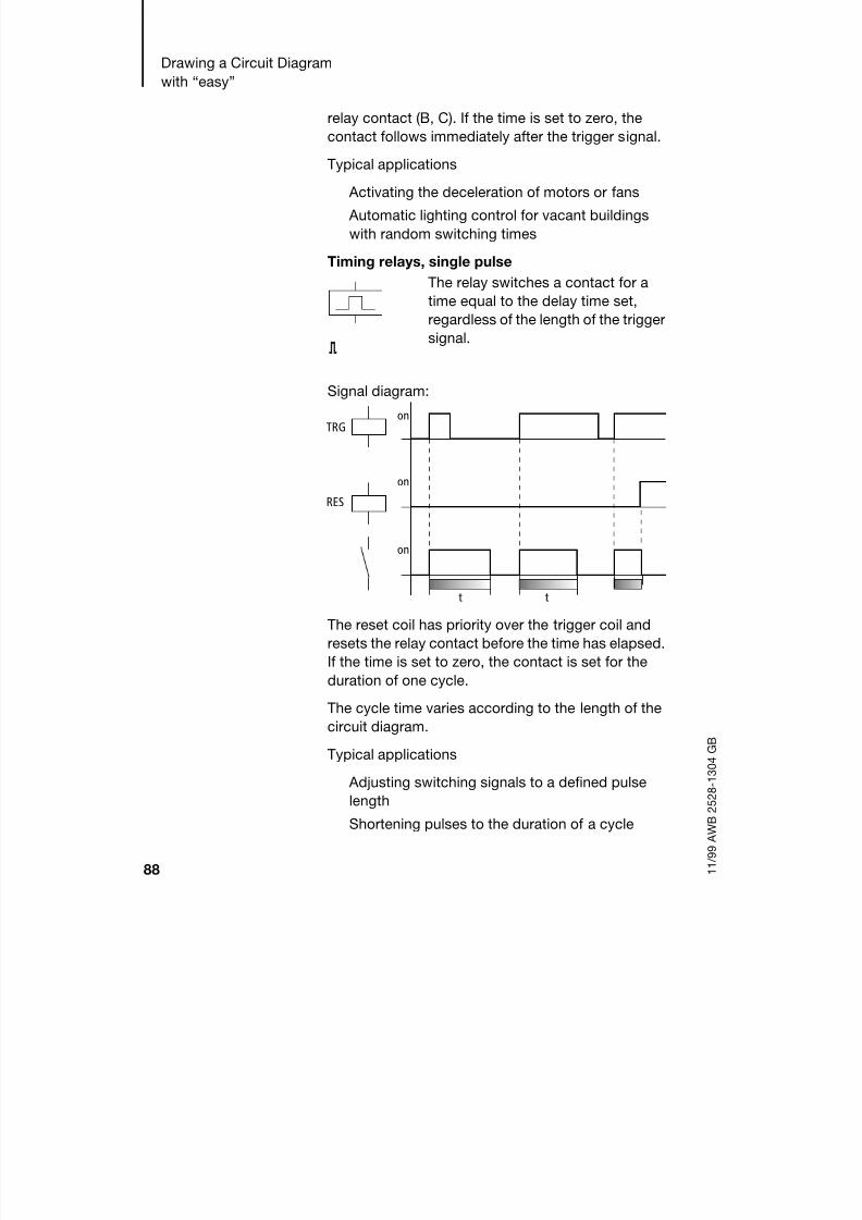
8/6/2019 Manual Easy 600
http://slidepdf.com/reader/full/manual-easy-600 91/229
Drawing a Circuit Diagram
with “easy”
88 1 1 / 9 9 A W B 2 5 2 8 - 1 3 0 4 G B
relay contact (B, C). If the time is set to zero, the
contact follows immediately after the trigger signal.
Typical applications
Activating the deceleration of motors or fans
Automatic lighting control for vacant buildings
with random switching times
Timing relays, single pulse
Signal diagram:
The reset coil has priority over the trigger coil and
resets the relay contact before the time has elapsed.If the time is set to zero, the contact is set for the
duration of one cycle.
The cycle time varies according to the length of the
circuit diagram.
Typical applications
Adjusting switching signals to a defined pulse
lengthShortening pulses to the duration of a cycle
The relay switches a contact for a
time equal to the delay time set,
regardless of the length of the triggersignal.
ü
on
on
TRG
RES
on
t t

8/6/2019 Manual Easy 600
http://slidepdf.com/reader/full/manual-easy-600 92/229

8/6/2019 Manual Easy 600
http://slidepdf.com/reader/full/manual-easy-600 93/229
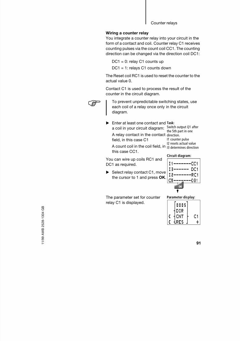
8/6/2019 Manual Easy 600
http://slidepdf.com/reader/full/manual-easy-600 94/229
Counter relays
91 1 1 / 9 9 A W B 2 5 2 8 - 1 3 0 4 G B
Wiring a counter relay
You integrate a counter relay into your circuit in the
form of a contact and coil. Counter relay C1 receivescounting pulses via the count coil CC1. The counting
direction can be changed via the direction coil DC1:
DC1 = 0: relay C1 counts up
DC1 = 1: relays C1 counts down
The Reset coil RC1 is used to reset the counter to the
actual value 0.
Contact C1 is used to process the result of thecounter in the circuit diagram.
To prevent unpredictable switching states, use
each coil of a relay once only in the circuit
diagram.
Enter at least one contact and
a coil in your circuit diagram:
A relay contact in the contactfield, in this case C1
A count coil in the coil field, in
this case CC1.
You can wire up coils RC1 and
DC1 as required.
Select relay contact C1, move
the cursor to 1 and press OK.
Task:Switch output Q1 afterthe 5th part in one
direction.I1 counter pulseI2 resets actual valueI3 determines direction
Circuit diagram:
The parameter set for counter
relay C1 is displayed.
Parameter display:
I1-------CC1I3------ DC1I2-------RC1
C1-------ÄQ1
f0005gsDIR n
Ä sCNT d C1Ä yRES b +

8/6/2019 Manual Easy 600
http://slidepdf.com/reader/full/manual-easy-600 95/229
Drawing a Circuit Diagram
with “easy”
92 1 1 / 9 9 A W B 2 5 2 8 - 1 3 0 4 G B
Determining counter frequency
The maximum counter frequency depends on the
length of the circuit diagram in “easy”. The number ofcontacts, coils and circuit connections used
determines the run time (cycle time) required to
process the “easy” circuit diagram.
Example: When using EASY 412-DC-TC with only
three circuit connections for counting, resetting and
outputting the result via the output, the counter
frequency may be 100 Hz.
To determine the cycle time refer to chapter 9page 178.
The maximum counter frequency depends on the
maximum cycle time.
Use the following formula to determine the maximum
counter frequency:
fc = maximum counter frequency
tc = maximum cycle time
0.8 = correction factor
Example
The maximum cycle time is tc = 4000 s (4 ms).
Parameters for counters
The parameter display for counters is used to change
the counter setpoint value and to enable or disable
parameter access.
fc1
2 tc----------------- 0,8=
fc1
2 4 ms----------------------- 0,8 100 Hz==
Setpoint Actual value
Direction coil
Counter coil Relay no.
Reset Parameter display
f0230g0000Ä sDIR nÄ sCNT d C1
Ä yRES b +

8/6/2019 Manual Easy 600
http://slidepdf.com/reader/full/manual-easy-600 96/229
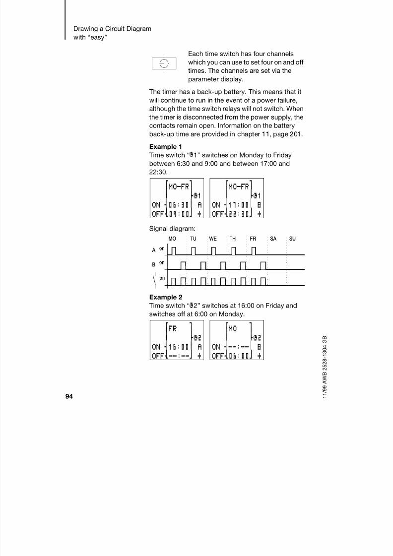
8/6/2019 Manual Easy 600
http://slidepdf.com/reader/full/manual-easy-600 97/229
Drawing a Circuit Diagram
with “easy”
94 1 1 / 9 9 A W B 2 5 2 8 - 1 3 0 4 G B
Each time switch has four channels
which you can use to set four on and off
times. The channels are set via theparameter display.
The timer has a back-up battery. This means that it
will continue to run in the event of a power failure,
although the time switch relays will not switch. When
the timer is disconnected from the power supply, the
contacts remain open. Information on the battery
back-up time are provided in chapter 11, page 201.
Example 1Time switch “Ö1” switches on Monday to Friday
between 6:30 and 9:00 and between 17:00 and
22:30.
Signal diagram:
Example 2
Time switch “Ö2” switches at 16:00 on Friday and
switches off at 6:00 on Monday.
fMO-FRgn dÖ1
ON s17:00n BOFFy22:30b +
fMO-FRgn dÖ1
ON s06:30n AOFFy09:00b +
fFR gn dÖ2
ON s16:00n AOFFy--:--b +
fMO gn dÖ2
ON s--:--n BOFFy06:00b +

8/6/2019 Manual Easy 600
http://slidepdf.com/reader/full/manual-easy-600 98/229
Time switch
95 1 1 / 9 9 A W B 2 5 2 8 - 1 3 0 4 G B
Signal diagram:
Example 3
Time switch “Ö3” switches on overnight at 22:00 on
Monday and switches off at 6:00 on Tuesday.
Signal diagram:
Example 4
The time settings of a time switch overlap. The clock
switches on at 16:00 on Monday, whereas on
Tuesday and Wednesday it switches on at 10:00. On
Monday to Wednesday the switching-off time is
22:00.
fMO gn dÖ3
ON s22:00n DOFFy06:00b +
If the Off time is before the On time, “easy” will
switch off on the following day.
fMO-WEgn dÖ4
ON s16:00n AOFFy22:00b +
fTU-WEgn dÖ4
ON s10:00n BOFFy00:00b +

8/6/2019 Manual Easy 600
http://slidepdf.com/reader/full/manual-easy-600 99/229
Drawing a Circuit Diagram
with “easy”
96 1 1 / 9 9 A W B 2 5 2 8 - 1 3 0 4 G B
Signal diagram:
Example 5
The power is removed between 15:00 and 17:00. The
relay drops out and remains off, even after the power
returns, since the first switching-off time was at
16:00.
Example 6
The time switch is to switch for 24 hours. Switch-on
time at 0:00 on Monday and switch-off time at 0:00
on Tuesday.
Switch-on and switch-off times always follow the
channel which switches first.
fMO-SUgn dÖ4
ON s12:00n AOFFy16:00b +
fMO-SUgn dÖ4
ON s12:00n BOFFy18:00b +
When it is switched on, “easy” always updates
the switching state on the basis of all the available
switching time settings.
fMO gn dÖ1
ON s00:00n AOFFy--:--b +
fDI gn dÖ1
ON s--:--n BOFFy00:00b +
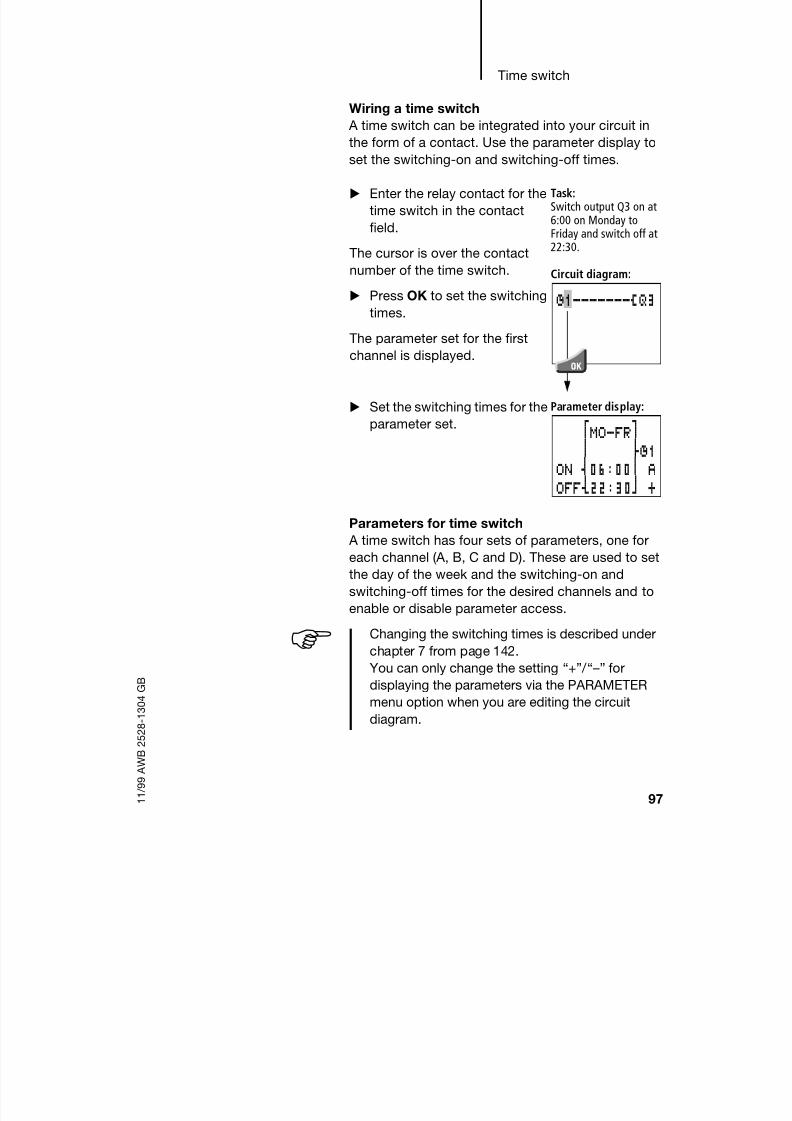
8/6/2019 Manual Easy 600
http://slidepdf.com/reader/full/manual-easy-600 100/229
Time switch
97 1 1 / 9 9 A W B 2 5 2 8 - 1 3 0 4 G B
Wiring a time switch
A time switch can be integrated into your circuit in
the form of a contact. Use the parameter display toset the switching-on and switching-off times.
Parameters for time switch
A time switch has four sets of parameters, one for
each channel (A, B, C and D). These are used to set
the day of the week and the switching-on and
switching-off times for the desired channels and toenable or disable parameter access.
Enter the relay contact for the
time switch in the contact
field.
The cursor is over the contact
number of the time switch.
Press OK to set the switchingtimes.
The parameter set for the first
channel is displayed.
Task:Switch output Q3 on at6:00 on Monday toFriday and switch off at22:30.
Circuit diagram:
Set the switching times for the
parameter set.
Parameter display:
Ö1-------ÄQ3
fMO-FRg
n dÖ1ON s06:00n AOFFy22:30b +
Changing the switching times is described under
chapter 7 from page 142.
You can only change the setting “+” / “–” for
displaying the parameters via the PARAMETER
menu option when you are editing the circuit
diagram.
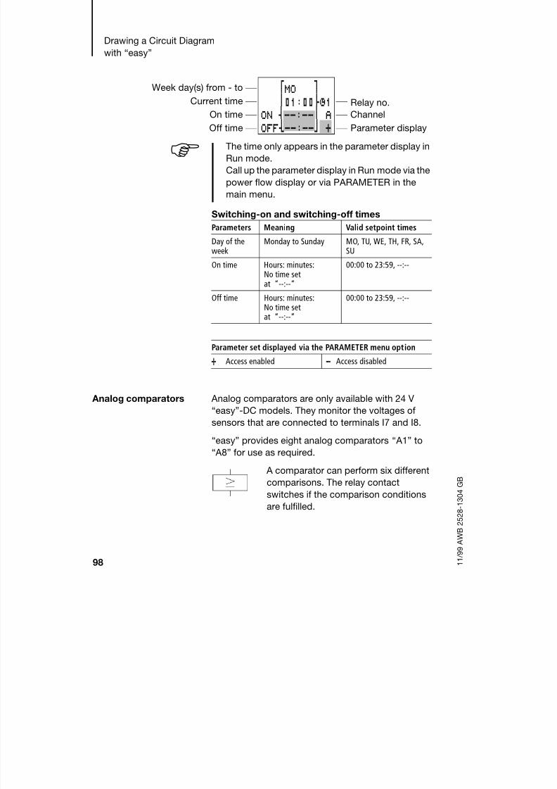
8/6/2019 Manual Easy 600
http://slidepdf.com/reader/full/manual-easy-600 101/229
Drawing a Circuit Diagram
with “easy”
98 1 1 / 9 9 A W B 2 5 2 8 - 1 3 0 4 G B
Switching-on and switching-off times
Analog comparators Analog comparators are only available with 24 V
“easy”-DC models. They monitor the voltages of
sensors that are connected to terminals I7 and I8.
“easy” provides eight analog comparators “ A1” to
“ A8” for use as required.
A comparator can perform six different
comparisons. The relay contact
switches if the comparison conditions
are fulfilled.
Week day(s) from - to
Current time Relay no.On time Channel
Off time Parameter display
The time only appears in the parameter display in
Run mode.
Call up the parameter display in Run mode via the
power flow display or via PARAMETER in the
main menu.
fMO g
n01:00dÖ1ON s--:--n AOFFy--:--b +
Parameters Meaning Valid setpoint times
Day of theweek
Monday to Sunday MO, TU, WE, TH, FR, SA,SU
On time Hours: minutes:No time setat “--:--”
00:00 to 23:59, --:--
Off time Hours: minutes:No time setat “--:--”
00:00 to 23:59, --:--
Parameter set displayed via the PARAMETER menu option
+ Access enabled - Access disabled

8/6/2019 Manual Easy 600
http://slidepdf.com/reader/full/manual-easy-600 102/229
Analog comparators
99 1 1 / 9 9 A W B 2 5 2 8 - 1 3 0 4 G B
I7 I8, I7 I8
I7 setpoint, I7 setpoint
I8 setpoint, I8 setpointBoth the setpoint value and the actual value
correspond to the measured voltages.
Resolution of the voltage values:
0.0 to 10.0 V in 0.1 V steps
From 10 V to 24 V the actual value stays at 10.0.
You can enter the setpoint values for a comparison
while you are creating the circuit diagram or in theparameter display in Run mode.
Typical applications
Evaluating the analog values of sensors, e.g. in
order measure the pressure or temperature.
Two-step controllers
Example:
Analog comparator “ A1” latches (sets) relay Q1 if the
actual value drops below the
lower setpoint value of 7.1 V.
Comparator “ A2” unlatches
(resets) the relay if it rises above the upper setpoint
value of 7.5 V. Thus the difference (switching
hysteresis) between the two voltage setpoint values
is 0.4 V.
The parameter settings are:
I1uA1----SQ1hA2----RQ1
ANALOGI7 w g
n § dA17.1y b +
ANALOGI7 w g
n $ dA27.5y b +

8/6/2019 Manual Easy 600
http://slidepdf.com/reader/full/manual-easy-600 103/229
Drawing a Circuit Diagram
with “easy”
100 1 1 / 9 9 A W B 2 5 2 8 - 1 3 0 4 G B
Signal diagram:
A1 sets relay output Q1 (A) up to a voltage of 7.1 V.The hysteresis (B) is between 7.1 V and 7.5 V. At
7.5 V, A2 causes the relay to reset (C). Q1 drops out
and does not pick up again until A1 is set at 7.1 V (D).
on
7,5
7,1
10
5
[V]
A1 A2
I7
A1
A B C D
Analog signals of sensors typically fluctuate by
several millivolts. For stable set and reset
switching the setpoints should differ by at least
0.2 V (switching hysteresis).
Caution
To prevent the uncontrolled switching of the
relay coils only use the Set and Reset functions
with the analog comparators.

8/6/2019 Manual Easy 600
http://slidepdf.com/reader/full/manual-easy-600 104/229
Analog comparators
101 1 1 / 9 9 A W B 2 5 2 8 - 1 3 0 4 G B
Wiring analog comparators
You integrate an analog comparator into your circuit
in the form of a contact. Use the parameter display toselect one of six possible comparators and enter the
setpoint values.
Press OK to finish or enter another setpoint value.
Press ESC to return to the circuit diagram
display.
Enter the relay contact for the
analog comparator in the
contact field.
The cursor is then located on the
contact number of the
comparator.
Press OK to switch to the
parameter display.
Task:Output Q3 shouldswitch on at a certainvalue.
Circuit diagram:
The parameter set for the first comparator is
displayed.
Use ú í to move the cursor to the field. UseÍÚ
to select one of the comparator relays.
A1-------SQ3
I7 I8 I7 setpoint I7 setpoint
I7 I8 I8 setpoint I8 setpoint
ANALOGI7 w g
n $ dA1I8 y b +
ANALOGI7 w g
n $ dA10.0y b +
ANALOGI7 w g
n § dA10.0y b +
ANALOGI7 w g
n § dA1I8 y b +
ANALOGI8 w g
n $ dA10.0y b +
ANALOGI8 w g
n § dA10.0y b +

8/6/2019 Manual Easy 600
http://slidepdf.com/reader/full/manual-easy-600 105/229
Drawing a Circuit Diagram
with “easy”
102 1 1 / 9 9 A W B 2 5 2 8 - 1 3 0 4 G B
Parameter sets for analog comparators
The parameter display for analog comparators can
be used to set the comparison “” or “” and toenable or disable the parameter access.
If you want to compare an input with a setpoint value,
you must also set the setpoint value.
Input I7 Curr. value
Compare fctn. Relay no.
Input I8 Parameter display
Curr. value
ANALOGI7 w8.0 Vg
n § dA1I8 y4.2 Vb +
Input I7/I8 Curr. value
Compare fctn. Relay no.
Setpoint Parameter display
The actual values are only displayed in Run
mode. Call up the parameter display in Run mode
via the power flow display or via PARAMETER in
the main menu.
You cannot set parameters when comparing two
values.
ANALOGI7 w8.0 Vg
n $d A1
Parameters Function Meaning
Compare fctn. $ Greater than or equal to
§ Less than or equal to
Setpoint 0.0 Setpoint value, 0.0 to 9.9, 10.0 =overflow
Parameter set displayed via the PARAMETER menu option
+ Access enabled - Access disabled

8/6/2019 Manual Easy 600
http://slidepdf.com/reader/full/manual-easy-600 106/229
Text display
103 1 1 / 9 9 A W B 2 5 2 8 - 1 3 0 4 G B
Text display EASY 600 allows you to display eight user-defined
texts which can be edited in EASY-SOFT from V. 2.0
upwards. The texts are saved in the EASY-SOFT file*.eas or on the “easy-M-16K” memory card for
EASY 600.
Example
Circuit diagram symbols for text display
LCD display
Up to 12 characters per line and up to 4 lines can be
displayed.
Variables
Actual values and setpoints of timing relays and
counters, scaled actual values from analog input I7or I8, as well as the current time are displayed
automatically in lines 2 or 3, characters 5 to 8
(characters 5 to 9 for time display, see 13:51 in
example below). If you have entered text at these
locations, they will be overwritten by the variable
values. Enter a blank space as the placeholder (at
13:51 in the example), in order to continue text after
the variable display.
Example: TIME13:51
Contacts Make contact D
Break contact
Numbers 1 to 8
Coils D
Numbers 1 to 8Coil functions Ä,S,R,ä
THINKFUTURESWITCH TOGREEN

8/6/2019 Manual Easy 600
http://slidepdf.com/reader/full/manual-easy-600 107/229

8/6/2019 Manual Easy 600
http://slidepdf.com/reader/full/manual-easy-600 108/229

8/6/2019 Manual Easy 600
http://slidepdf.com/reader/full/manual-easy-600 109/229
Drawing a Circuit Diagram
with “easy”
106 1 1 / 9 9 A W B 2 5 2 8 - 1 3 0 4 G B
Circuit diagram symbols for jumps
Function
If the jump coil is triggered, the circuit connectionscoming directly after it will not be processed. The
states of the coils before the jump will be retained,
unless they are overwritten in circuit connections that
were not missed by the jump. Jumps are always
made forwards, i.e. the jump ends on the first contact
with the same number as that of the coil.
Coil = jump when 1
Contact only at the first leftmost contact = Jumpdestination
The Jump contact point will always be set to 1
Contact Make contact :
(can only be used as first leftmost contact)
Numbers 1 to 8
Coils ÄNumbers 1 to 8
Coil function Ä
Backward jumps are not possible with “easy” due
to the way it operates. If the jump label does not
come after the jump coil, the jump will be made to
the end of the circuit diagram. The last circuit
connection will also be skipped.
If a jump destination is not preset, the jump will bemade to the end of the circuit diagram.
Multiple use of the same jump coil and jump
contact is possible as long as this is implemented
in pairs, i.e.
Coil Ä:1/jumped range/Contact :1,
Coil Ä:1/jumped range/Contact :1 etc.

8/6/2019 Manual Easy 600
http://slidepdf.com/reader/full/manual-easy-600 110/229
Jumps
107 1 1 / 9 9 A W B 2 5 2 8 - 1 3 0 4 G B
Power flow display
Jumped ranges are indicated by the coils in the
power flow display.
All coils after the jump coil are shown with the symbol
of the jump coil.
Example
A selector switch allows two different sequences to
be set.
Sequence 1: Switch on Motor 1 immediately.
Sequence 2: Switch on Guard 2, Wait time, then
switch on Motor 1.
Contacts and relays used:
I1 Sequence 1
I2 Sequence 2
I3 Guard 2 moved out
I12 Motor-protective circuit-breaker
switched on
Q1 Motor 1
Q2 Guard 2
T1 Wait time 30.00 s, on-delayed
D1 Text “Motor-protective circuit-breaker
tripped”
Attention
The states of jumped circuit connections are
retained. The time value of timing relays thathave been started will continue to run.

8/6/2019 Manual Easy 600
http://slidepdf.com/reader/full/manual-easy-600 111/229
Drawing a Circuit Diagram
with “easy”
108 1 1 / 9 9 A W B 2 5 2 8 - 1 3 0 4 G B
Example circuits Basic circuits
The “easy” circuit diagram is created using ladder
diagrams. This section contains a few circuitsintended to demonstrate the possibilities for your
own circuit diagrams.
The values in the logic table have the following
meanings
for contacts:
0 = make contact open, break contact closed
1 = make contact closed, break contact openfor relay coils Qx:
0 = coil not energized
1 = coil energized
Circuit diagram: Power flow display: I1 selected:
Range from jump label 1 processed.
Jump to label 8.
Range to jump label 8 skipped.
Jump label 8, circuit diagram processed fromthis point on.
I1-------Ä:1I2-------Ä:2:1--------uÄQ1
hRQ2---------Ä:8:2-------ÄQ2Q2-I3----TT2
T2-------ÄQ1:8i12-------ÄD1
I1----------------------------Ä:1I2--------:1:1--------------------------------uuuuÄQ1
hhhhRQ2------------------------------------Ä:8:2--------------------------------:8Q2-I3-----:8
T2--------:8:8i12-------ÄD1

8/6/2019 Manual Easy 600
http://slidepdf.com/reader/full/manual-easy-600 112/229
Example circuits
109 1 1 / 9 9 A W B 2 5 2 8 - 1 3 0 4 G B
Negation
Negation means that the contact opens, rather than
closes, when it is actuated (NOT circuit).In the “easy” circuit diagram,
press the ALT button to toggle
contact I1 between break and
make contact.
Logic table:
Permanent contact
To energize a relay coil
continuously, make a
connection of all contact fields
from the coil to the leftmost
position.
Logic table:
Series connection
Q1 is controlled by a series
circuit consisting of three make
contacts (AND circuit).
Q2 is controlled by a series
circuit consisting of three break
contacts (NOR circuit).
In the “easy” circuit diagram, you can connect up to
three make or break contacts in series within a circuit
connection. Use “M” marker relays if you need to
connect more than three make contacts in series.
I1 Q1
10 01
--- Q1
1 1
i1-------ÄQ1
---------ÄQ1
I1-I2-I3-ÄQ1
i1-i2-i3-ÄQ2

8/6/2019 Manual Easy 600
http://slidepdf.com/reader/full/manual-easy-600 113/229
Drawing a Circuit Diagram
with “easy”
110 1 1 / 9 9 A W B 2 5 2 8 - 1 3 0 4 G B
Logic table:
Parallel connectionQ1 is controlled by a parallel
circuit consisting of three make
contacts (OR circuit).
A parallel circuit of break
contacts controls Q2 (NAND
circuit).
Logic table:
Changeover circuit
A changeover circuit is made in
“easy” using two series
connections that are combined
to form a parallel connection
(XOR).
XOR means that this circuit is an
“Exclusive OR circuit”. Only if one contact switches,can the coil be energized.
I1 I2 I3 Q1 Q2
0101
0011
0000
0000
1000
0101
0011
1111
0001
0000
I1 I2 I3 Q1 Q2
0101
0011
0000
0111
1111
0101
0011
1111
1111
1110
I1u------ÄQ1I2sI3k
i1u------ÄQ2i2s
i3k
I1-i2u---ÄQ1i1-I2k

8/6/2019 Manual Easy 600
http://slidepdf.com/reader/full/manual-easy-600 114/229
Example circuits
111 1 1 / 9 9 A W B 2 5 2 8 - 1 3 0 4 G B
Logic table
Latching circuit
A combination of a series and
parallel connection is used to
wire a latching circuit.
Latching is established by
contact Q1 which is parallel to
I1. If I1 is actuated and
reopened, the current flows via
contact Q1 until I2 is actuated.
Logic table
Latching circuits are used to switch machines on and
off. The machine is switched on at the input terminalsvia make contact S1 and is switched off via break
contact S2.
S2 opens the connection to the control voltage in
order to switch off the machine. This ensures that the
machine can be switched off, even in the event of a
wire break. I2 is always closed when not actuated.
I1 I2 Q1
0101
0011
0110
I1 I2 Contact Q1 Coil Q1
0101
0011
0000
0001
101
011
111
011
I1uI2----ÄQ1Q1k
S1 make contact on I1S2 break contact on I2

8/6/2019 Manual Easy 600
http://slidepdf.com/reader/full/manual-easy-600 115/229
Drawing a Circuit Diagram
with “easy”
112 1 1 / 9 9 A W B 2 5 2 8 - 1 3 0 4 G B
A self-latching circuit with wire
break monitoring can
alternatively be wired using theSet and Reset coil functions.
Relay Q1 is latched when I1 is
switched on. I2 inverts the break
contact signal from S2 and does
not switch until S2 is actuated.
In this way, the machine is switched off if or when a
wire breaks.
Retain the order in which both coils are wired in the“easy” circuit diagram: wire first the S coil and then
the R coil. This means that the machine will be
switched off when I2 is actuated, even if I1 is
switched on.
Impulse relay
An impulse relay is often used
for controlling lighting such as
for staircase lighting.Logic table:
I1 State Q1 Q1
0101
0011
0110
I1-------SQ1i2-------RQ1
S1 make contact on I1S2 break contact on I2
S1 make contact on I1
I1-------äQ1

8/6/2019 Manual Easy 600
http://slidepdf.com/reader/full/manual-easy-600 116/229
Example circuits
113 1 1 / 9 9 A W B 2 5 2 8 - 1 3 0 4 G B
On-delayed timing relay
The on-delay can be used to
gate short pulses or to initiateanother movement with a time
delay when a machine is
started.
The parameter settings for T1
are:
Timing function on-delayed:
“X
”Time value and range:
10 seconds
If I1 is switched on, coil “T” of T1 is energized. After
10 seconds, T1 switches the marker relay M1. If I1 is
switched off, relay coils T1 and M1 drop out.
Logic table:
Star-delta starting
You can implement two star-delta circuits with
“easy”. The advantage of “easy” is that you can
select any changeover time between star and delta
contactors and any wait time between switching off
the star contactor and switching on the delta
contactor.
I1 T1 M1011
001
001
S1 make contact on I1
I1-------TT1T1-------ÄM1
X w gS n10.00nÄ sTRG dT1
yRES b +

8/6/2019 Manual Easy 600
http://slidepdf.com/reader/full/manual-easy-600 117/229
Drawing a Circuit Diagram
with “easy”
114 1 1 / 9 9 A W B 2 5 2 8 - 1 3 0 4 G B
N
K1M
K1M
K1M
K1T
K1T
K3M
K3M
K5M
K5M
L
S1
S2
K3M
1 12 2
Q1
I1L N
Q2
K3M K5MK1M
N
K1M
L
N
S1
S2

8/6/2019 Manual Easy 600
http://slidepdf.com/reader/full/manual-easy-600 118/229
Example circuits
115 1 1 / 9 9 A W B 2 5 2 8 - 1 3 0 4 G B
Function of the “easy” circuit diagram:
Start/Stop of switching using
external push-button actuatorsS1 and S2. The mains contactor
starts the “easy” timing relay.
I1 Mains contactor
switched on
Q1 Star contactor ON
Q2 Delta contactor ON
T1 Star-delta changeover time (10 to 30 s, X)T2 Wait time between star off, delta on
(30, 40, 50, 60 ms, X)
If your “easy” has an integral time switch, you can
combine star-delta starting with the time switch
function. In this case, use “easy” to switch the mains
contactor as well.
4x shift register
You can use a shift register for storing an item of
information, e.g. sorting of parts into good and bad
two, three or four transport steps further on.
A shift pulse and the value (0 or 1) to be shifted are
needed for the shift register.
The shift register's Reset input is used to clear any
values that are no longer needed. The values in the
shift register pass through the register in the
following order.
1st, 2nd, 3rd, 4th storage position.
I1u------TT1dt1----ÄQ1dT1----TT2hT2----ÄQ2

8/6/2019 Manual Easy 600
http://slidepdf.com/reader/full/manual-easy-600 119/229
Drawing a Circuit Diagram
with “easy”
116 1 1 / 9 9 A W B 2 5 2 8 - 1 3 0 4 G B
Block diagram for the 4x shift register:
Function:
Assign the contents “bad” to the value 0. This
ensures that no bad parts will be reused if the shift
register is accidentally deleted.
I1 Shift pulse (PULSE)
I2 Information (good/bad) to be shifted
(VALUE)
I3 Clear content of the shift register
(RESET)
M1 1st storage position
M2 2nd storage position
M3 3rd storage position
M4 4th storage position
M7 Marker relay for cyclical pulse
M8 Cyclical pulse for shift pulse
Pulse Value Storage location
1 2 3 4
1 1 1 0 0 0
2 0 0 1 0 0
3 0 0 0 1 0
4 1 1 0 0 1
5 0 0 1 0 0
Reset = 1 0 0 0 0

8/6/2019 Manual Easy 600
http://slidepdf.com/reader/full/manual-easy-600 120/229
Example circuits
117 1 1 / 9 9 A W B 2 5 2 8 - 1 3 0 4 G B
How does the shift register work?
The shift pulse is switched on for exactly one cycle.
To do this, the shift pulse is generated by evaluatingthe change from I1 “off” to I1 “on” – the rising edge.
In this way, therefore, the cyclical processing of
“easy” is used to trigger the shift pulse.
When I1 is switched on for the first time, marker relay
contact M7 is switched off and the break contact is
closed during the first pass through the cycle. Thus,
the series circuit consisting of I1, break contact M7
(closed) and M8 is switched on. Although M7 isswitched on, this does not yet affect contact M7.
The contact of M8 (make contact) was still open
during the first cycle so a shift pulse cannot yet be
generated. When the relay coil M8 is activated,
“easy” transfers the result to the contacts.
In the second cycle, break contact M7 opens. The
series circuit is now open. The contact M8 is
switched on from the result of the first cycle. Now, all
Generate shift pulse
Set 4th storage position
Clear 4th storage position
Set 3rd storage position
Clear 3rd storage position
Set 2nd storage position
Clear 2nd storage position
Set 1st storage position
Clear 1st storage position
Clear all storage positions
I1um7----ÄM8
h------ÄM7M8uM3----SM4dm3----RM4dM2----SM3dm2----RM3dM1----SM2dm1----RM2dI2----SM1
hi2----RM1I3------uRM1
dRM2dRM3hRM4
8/6/2019 Manual Easy 600
http://slidepdf.com/reader/full/manual-easy-600 121/229
Drawing a Circuit Diagram
with “easy”
118 1 1 / 9 9 A W B 2 5 2 8 - 1 3 0 4 G B
the storage positions are either set or reset in
accordance with the series circuit.
If the relay coils were activated, “easy” transfers theresult to the contacts. M8 is now open once more.
No new pulse can be formed until I1 has opened,
since M7 is open for as long as I1 is closed.
How does the value reach the shift register?
When shift pulse M8 = “on”, the state of I2 (value) is
transferred to storage position M1.
If I2 is switched on, M1 is set. If I2 is switched off, M1
is switched off via break contact I2.
How is the result shifted?
“easy” activates the coils in accordance with the
circuit connection and its result, from top to bottom.
M4 assumes the value of M3 (value 0 or 1) before M3
assumes the value of M2. M3 assumes the value of
M2, M2 the value of M1 and M1 the value of I2.
Why are the values not constantly overwritten?In this example, the coils are controlled only by the
“S” and “R” functions, i.e. the values are retained in
on or off states even though the coil is not constantly
switched on. The state of the coil changes only if the
circuit connection up to the coil is switched on. In
this circuit, the marker relay is therefore either set or
reset.

8/6/2019 Manual Easy 600
http://slidepdf.com/reader/full/manual-easy-600 122/229
Example circuits
119 1 1 / 9 9 A W B 2 5 2 8 - 1 3 0 4 G B
The circuit connections of the coils (storage
positions) are only switched on via M8 for one cycle.
The result of activating the coils is stored in “easy” until a new pulse changes the state of the coils.
How are all the storage positions cleared?
When I3 is switched on, all the “R” coils of storage
positions M1 to M4 are reset, i.e. the coils are
switched off. Since the reset was entered at the end
of the circuit diagram, the reset function has priority
over the set function.
How can the value of a storage position betransferred?
Use the make or break contact of storage positions
M1 to M4 and wire them to an output relay or in the
circuit diagram according to the task required.
Running light
An automatic running light can be created by slightlymodifying the shift register circuit.
One relay is always switched on. It starts at Q1, runs
through to Q4 and then starts again at Q1.
The marker relays for storage positions M1 to M4 are
replaced by relays Q1 to Q4.
The shift pulse I1 has been
automated by the flasher relay
T1. The cycle pulse M8 remains
as it is.
Ü w g
S n00.50nÄ sTRG dT1
yRES b +

8/6/2019 Manual Easy 600
http://slidepdf.com/reader/full/manual-easy-600 123/229
Drawing a Circuit Diagram
with “easy”
120 1 1 / 9 9 A W B 2 5 2 8 - 1 3 0 4 G B
On the first pass, the value is switched on once by
break contact M9. If Q1 is set, M9 is switched on.
Once Q4 (the last storage position) has beenswitched on, the value is passed back to Q1.
Try changing the times.
Flasher relay
Generate shift pulse
Clear first valueSet 4th storage position
Clear 4th storage position
Set 3rd storage position
Clear 3rd storage position
Set 2nd storage position
Clear 2nd storage position
Set 1st storage position
Enter first value (=1)Clear 1st storage position
---------TT1T1um7----ÄM8h------ÄM7
Q1-------SM9M8uQ3----SQ4dQ4----RQ4dQ2----SQ3dQ3----RQ3dQ1----SQ2dQ2----RQ2dQ4u---SQ1
dm9khQ1----RQ1

8/6/2019 Manual Easy 600
http://slidepdf.com/reader/full/manual-easy-600 124/229
Example circuits
121 1 1 / 9 9 A W B 2 5 2 8 - 1 3 0 4 G B
Stairwell lighting
For a conventional circuit you would need at least
five space units in the distribution system, i.e.one impulse relay, two timing relays and two auxiliary
relays.
“easy” requires only four space units. A fully
functioning stairwell lighting system can be set up
with five terminals and the “easy” circuit diagram.
Four such stairwell circuits can be implemented
with one “easy” device.
N
L
S1
S2
S3
K3TK1 K2T
K4
K4
K5
K5
K3T K1
K2T
K5
K5
5 s 6 min
H1
H2
H3

8/6/2019 Manual Easy 600
http://slidepdf.com/reader/full/manual-easy-600 125/229
Drawing a Circuit Diagram
with “easy”
122 1 1 / 9 9 A W B 2 5 2 8 - 1 3 0 4 G B
NL
S1
S2
S3
H1
H2
H3
1 2
Q1
I1L N
Button pressed briefly Light ON or OFF. The impulse relay functionwill even switch off Continuous lighting.
Light off after 6 min. with Continuouslighting this function is not active.
Button pressed for morethan 5 s
Continuous lighting

8/6/2019 Manual Easy 600
http://slidepdf.com/reader/full/manual-easy-600 126/229
Example circuits
123 1 1 / 9 9 A W B 2 5 2 8 - 1 3 0 4 G B
Meaning of the contacts and relays used:
I1 Button ON/OFF
Q1 Output relay for light ON/OFF
M1 Marker relay. This is used to blockthe “switch off automatically after
6 minutes” function for continuous
lighting.
T1 Cycle pulse for switching Q1 on and off,
(ü, single-pulse with value 00.00 s)
T2 Scan to determine how long the button
was pressed.
If pressed longer than 5 s,switch on continuous lighting
(X, on-delayed, value 5 s).
T3 Switch off after the light has been switched
on for 6 min.
(X, on-delayed, value 6:00 min.)
T4 Switch off after 4 hours continuous lighting
(X, on-delayed, value 4:00 h).
The “easy” circuit diagram for thefunctions described above lookslike this:
The enhanced “easy” circuitdiagram: after four hours, thecontinuous lighting is alsoswitched off.
I1-------TT2T2-------SM1I1u------äQ1T3kQ1-m1----TT3q1-------RM1
I1------uTT1hTT2
T2-------SM1T1u------äQ1T3sT4k
Q1um1----TT3h------TT4q1-------RM1

8/6/2019 Manual Easy 600
http://slidepdf.com/reader/full/manual-easy-600 127/229
Drawing a Circuit Diagram
with “easy”
124 1 1 / 9 9 A W B 2 5 2 8 - 1 3 0 4 G B
If you use “easy” with a time switch, you can define
both the stairwell lighting and the continuous lighting
periods via the time switch.If you use “easy” with analog inputs, you can
optimise the stairwell lighting, via a brightness
sensor to suit the lighting conditions.

8/6/2019 Manual Easy 600
http://slidepdf.com/reader/full/manual-easy-600 128/229
125 1 1 / 9 9 A W B 2 5 2 8 - 1 3 0 4 G B
6 Saving and Loading Circuit Diagrams
You can either use the “easy” interface to save circuit
diagrams to a memory card or use EASY-SOFT and
a transmission cable to transfer them to a PC.
“easy”-X
“easy” models without buttons can be loaded with a
circuit diagram via EASY-SOFT or automatically fromthe fitted memory card every time the power supply
is switched on.
Interface
The “easy” interface is covered.
DANGER of electric shock with “easy”-ACunits!
If the voltage terminals for phase (L) and neutral
conductor (N) are swapped over, the connected
230 V/115 V voltage will be present at the “easy”
interface. There is a danger of electric shock if
the plug is not properly connected or if
conductive objects are inserted into the socket.

8/6/2019 Manual Easy 600
http://slidepdf.com/reader/full/manual-easy-600 129/229

8/6/2019 Manual Easy 600
http://slidepdf.com/reader/full/manual-easy-600 130/229
Memory card
127 1 1 / 9 9 A W B 2 5 2 8 - 1 3 0 4 G B
The following information is saved to the memory
card:
the circuit diagram
all parameter settings of the circuit diagram
all display texts with functions
system settings
debounce (input delay)
P buttons
password
retention on/off
Insert the memory card in the open interface slot.
Loading or storing the circuit diagramYou can only transfer circuit diagrams in Stop mode.
“easy”-X models without buttons and LCD can be
loaded with a circuit diagram automatically from the
fitted memory card every time the power supply is
switched on. If the circuit diagram on the memory
card is not valid, the circuit diagram already in the
“easy” unit is retained.
EASY 412 ( = easy-M-8K): EASY 600 ( = easy-M-16K):
With “easy” you can insert and remove the
memory card even if the power feed is switched
on, without the risk of losing data.
2
11
2

8/6/2019 Manual Easy 600
http://slidepdf.com/reader/full/manual-easy-600 131/229
Saving and Loading Circuit
Diagrams
128 1 1 / 9 9 A W B 2 5 2 8 - 1 3 0 4 G B
Switch to Stop mode.
Select “PROGRAM...” from the main menu.
Select the “CARD...” menuoption.
The “Card...” menu option will
only appear if you have inserted
a functional memory card.
You can transfer a circuit
diagram from “easy” to the card
and from the card to the “easy”
memory or delete the content of
the card.
After transmission, remove the memory card and
close the cover.
Saving a circuit diagram to the card
Select “DEVICE-> CARD”.
Confirm the prompt with OK
to delete the contents of the
memory card and replace it
with the “easy” circuit
diagram.
Press ESC to cancel.
PROGRAMDELETE PROGCARD...
DEVICE-CARDCARD-DEVICE
DELETE CARD
If the operating voltage fails during
communication with the card, repeat the last
procedure since “easy” may not have transferred
or deleted all the data.
REPLACE ?

8/6/2019 Manual Easy 600
http://slidepdf.com/reader/full/manual-easy-600 132/229
Memory card
129 1 1 / 9 9 A W B 2 5 2 8 - 1 3 0 4 G B
Loading a circuit diagram from the card
Select the “CARD->
DEVICE” menu option. Press OK to confirm the
prompt if you want to delete
the “easy” memory and
replace it with the card
content.
Press ESC to cancel.
If a problem occurs during
transmission, “easy” will displaythe message “PROG INVALID”.
This either means that the
memory card is empty or that
the circuit diagram on the card
contains function relays that “easy” does not
recognise.
The “time switch” function relays only work with
“easy” versions with a real-time clock (type
“easy”-C).
The “analog comparator” function relay is only
used with “easy”-DC 24 V DC versions.
Relays with text display, jumps and “S”, “R”
markers only work with EASY 600 versions.
Deleting a circuit diagram from the card
Select the “DELETE CARD” menu option.
Press OK to confirm the
prompt and to delete the
card content.
Press ESC to cancel.
DEVICE-CARDCARD-DEVICEDELETE CARD
INVALID PROG
If the memory card is password-protected, the
password will also be transferred to the “easy” memory and will be active immediately.
DELETE ?

8/6/2019 Manual Easy 600
http://slidepdf.com/reader/full/manual-easy-600 133/229

8/6/2019 Manual Easy 600
http://slidepdf.com/reader/full/manual-easy-600 134/229

8/6/2019 Manual Easy 600
http://slidepdf.com/reader/full/manual-easy-600 135/229
132 1 1 / 9 9 A W B 2 5 2 8 - 1 3 0 4 G B

8/6/2019 Manual Easy 600
http://slidepdf.com/reader/full/manual-easy-600 136/229
133 1 1 / 9 9 A W B 2 5 2 8 - 1 3 0 4 G B
7 “easy” Settings
Settings can only be carried out on “easy” models
provided with buttons and LCD display.
EASY-SOFT from V 2.0 upwards can be used to set
all models.
Password protection The “easy” circuit diagram, function relay settings
and system parameters can be password protected.
In this case the password consists of a value
between 0001 and 9999. The number combination
0000 is used to delete a password.
Password protection blocks access to the circuit
diagram menu and System menu and thus offers
protection against
unauthorised starting or modification of thecircuit diagram
modification of function relay parameters via the
circuit diagram
transfer of a circuit diagram from and to the
memory card
modification of system parameters
set new password
Debounce (input delay) ON/OFFP buttons ON/OFF
menu language selection
Only parameters marked with “–” are password-
protected. Parameters marked with “+” can still
be modified via the PARAMETER menu.

8/6/2019 Manual Easy 600
http://slidepdf.com/reader/full/manual-easy-600 137/229
“easy” Settings
134 1 1 / 9 9 A W B 2 5 2 8 - 1 3 0 4 G B
The password does not offer protection against:
changing between operating modes Run or Stop.
setting the clock
access to the parameters of function relays
marked with “+”.
Setting the password
Passwords can be set in the System menu in both
Run or Stop operating modes. If, however, a
password is already activated, you cannot change to
the System menu.
Press DEL and ALT to call up the System menu.
Select the menu point “PASSWORD...” to enter
the password.
If a password has not been
entered already, “easy” will
switch directly to the passworddisplay and show four dashes:
No password available.
Set the password using the
cursor buttons:
ú í move to the 4-digit entry field
ú í select digit in password
ÍÚ set a value between 0 and 9.
A password that has been entered in “easy” is
transferred to the memory card together with the
circuit diagram, irrespective of whether it was
activated or not.
If this “easy” circuit diagram is loaded from the
memory card, the password will also be
transferred to “easy” and become activated
immediately.
ENTER PW Â
----
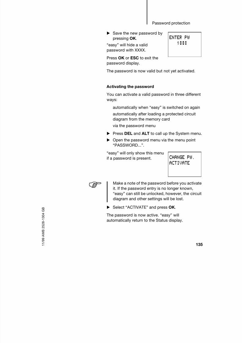
8/6/2019 Manual Easy 600
http://slidepdf.com/reader/full/manual-easy-600 138/229
Password protection
135 1 1 / 9 9 A W B 2 5 2 8 - 1 3 0 4 G B
Save the new password by
pressing OK.
“easy” will hide a validpassword with XXXX.
Press OK or ESC to exit the
password display.
The password is now valid but not yet activated.
Activating the password
You can activate a valid password in three different
ways:
automatically when “easy” is switched on again
automatically after loading a protected circuit
diagram from the memory card
via the password menu
Press DEL and ALT to call up the System menu.
Open the password menu via the menu point
“PASSWORD...”.
“easy” will only show this menu
if a password is present.
Select “ ACTIVATE” and press OK.
The password is now active. “easy” will
automatically return to the Status display.
ENTER PW1000
CHANGE PW.ACTIVATE
Make a note of the password before you activateit. If the password entry is no longer known,
“easy” can still be unlocked, however, the circuit
diagram and other settings will be lost.

8/6/2019 Manual Easy 600
http://slidepdf.com/reader/full/manual-easy-600 139/229
“easy” Settings
136 1 1 / 9 9 A W B 2 5 2 8 - 1 3 0 4 G B
You must unlock “easy” using the password before
you can edit a circuit diagram or enter the System
menu.
Unlocking “easy”
Unlocking “easy” will deactivate the password. You
can re-activate password protection later via the
password menu or by switching the power supply off
and on again.
Press OK to switch to the main menu.
The “PASSWORD...” entry will
flash.
Press OK to enter the
password entry menu.
“easy” will display the password
entry field.
Set the password using the
cursor buttons.
Confirm with OK.
If the password is correct, “easy” will switchautomatically to the Status display.
The “PROGRAM...” menu point
is now accessible so that you
can edit your circuit diagram.
The System menu is also
accessible.
PASSWORD...STOPPARAMETERSET CLOCK..
If “easy” shows “PROGRAM...” in the main menu
instead of “PASSWORD...” , this means that there
is no password protection active.
ENTER PW ÂXXXX
PROGRAM...STOPPARAMETERSET CLOCK..

8/6/2019 Manual Easy 600
http://slidepdf.com/reader/full/manual-easy-600 140/229

8/6/2019 Manual Easy 600
http://slidepdf.com/reader/full/manual-easy-600 141/229
“easy” Settings
138 1 1 / 9 9 A W B 2 5 2 8 - 1 3 0 4 G B
Password incorrect or not known
If you no longer know the exact password, you can
try to re-enter the password several times.Entered an incorrect password?
Re-enter the password.
After the fourth entry attempt
“easy” will ask whether you
wish to delete the circuit
diagram and data.
Press
ESC: No entry will be deleted.
OK: Circuit diagram, data and password will be
deleted.
“easy” will return to the Status display.
Pressing ESC will retain the circuit diagram and data.
You can then make another four attempts to enter
the password.
ENTER PW ÂXXXX
DELETE ALL?
If you no longer know the exact password, youcan press OK to unlock the protected “easy”. The
saved circuit diagram and all function relay
parameters will be lost.

8/6/2019 Manual Easy 600
http://slidepdf.com/reader/full/manual-easy-600 142/229
Changing the menu
language
139 1 1 / 9 9 A W B 2 5 2 8 - 1 3 0 4 G B
Changing the menu
language
EASY 412 provides five menu languages and
EASY 600 provides ten. These can be set as required
via the System menu.
Press DEL and ALT to call up the System menu.
Select “GB D F E I..” as required to modify the
menu language.
The language selection for the
first entry “GB” is displayed.
Use Í or Ú to select the
new menu language, e.g.Italian.
Confirm with OK.
“easy” will now show the new
menu language.
Press ESC to return to the
status display.
Language LCD display Abbreviaton
English ENGLISH GB
German DEUTSCH D
French FRANCAIS F
Spanish ESPANOL E
Italian ITALIANO I
Additional languages with EASY 600
Portuguese PORTUGUES –
Dutch NEDERLANDS –
Swedish SVENSKA –
Polish POLSKI –
Turkish TURKCE –
Language selection is only possible if “easy” is not
password-protected.
ENGLISH
GB D F E I
PASSWORD...RIT.INGR. ONP TASTO ONGB D F E I..

8/6/2019 Manual Easy 600
http://slidepdf.com/reader/full/manual-easy-600 143/229
“easy” Settings
140 1 1 / 9 9 A W B 2 5 2 8 - 1 3 0 4 G B
Changing parameters “easy” allows you to change function relay
parameters such as times and counter setpoints
without having to call up the circuit diagram. This ispossible regardless of whether “easy” is running a
program or is in Stop mode.
Press OK to switch to the main menu.
Start the parameter display by selecting
PARAMETER.
A complete parameter set will
be shown. In the example these
are the parameters for a timingrelay T1.
The following requirements
must be fulfilled for a parameter
set to be displayed:
a function relay must have been included in the
circuit diagram
the parameter set has been enabled for access,indicated by the “+” character at the bottom right
of the display.
Use the PARAMETER menu to access and modify
accessible parameter sets. Parameter sets for which
access is not enabled are not displayed. “easy”
therefore allows you to protect parameters with the
use of a password.
UseÍ orÚ to scroll through
the parameter sets. For this
the cursor must be located
on the identifier of the
function relay, in this case
T1.
ü w00.00g
S n30.00nsTRG dT1yRES b +
You can enable or disable parameter accessusing the parameter “+” or “–” characters
respectively in the circuit diagram.
ü w00.00gS n30.00n
sTRG dT1yRES b +

8/6/2019 Manual Easy 600
http://slidepdf.com/reader/full/manual-easy-600 144/229
Changing parameters
141 1 1 / 9 9 A W B 2 5 2 8 - 1 3 0 4 G B
Change the values for a parameter set:
ú í Move between the parameters
ÍÚChange the value of a parameter
OK Save parameter or
ESC Retain previous setting.
The cursor should still be on the identifier T1.
Press ESC to leave the parameter display.
Variable parameters for function relays
You can modify the relay parameters used in the
circuit diagram in three different ways:
All circuit diagram parameters can be adjusted in
Stop mode via the circuit diagram.
Setpoints can be modified in Run mode via thecircuit diagram.
Setpoints can be modified via the PARAMETER
menu.
The following setpoints can be modified:
the time value for timing relays
the counter setpoints of counter relays
the day and ON/OFF times of time switchesthe comparison setpoint of analog comparators.
In Run mode “easy” operates with a new setpoint as
soon has it has been modified in the parameter
display and saved with OK.
The parameter display is opened via the
PARAMETER menu. “Ä” coil terminals for
counters and times are not displayed here, evenif they have been wired.

8/6/2019 Manual Easy 600
http://slidepdf.com/reader/full/manual-easy-600 145/229
“easy” Settings
142 1 1 / 9 9 A W B 2 5 2 8 - 1 3 0 4 G B
Example: Changing switch times for outside
lighting
The outside lighting of a building is automaticallyswitched on from 19:00 to 23:30 Mondays to Fridays
in the “easy” circuit diagram.
The parameter set for the time
switch function relay 1 is saved
in channel “ A” and looks like
this.
The outside lighting is now required to switch on
between 19:00 and 22:00 on Saturdays.
Select PARAMETER from the main menu.
The first parameter set is displayed.
Use Í or Ú to scroll through the parameter sets
until channel A of time switch 1 is displayed.
PressÍ
to select the nextempty parameter set, in this
case channel B of time
switch 1.
The current time is 15:21.
Change the value for the day
interval from MO to SA:
ú í Move between the
parameters
ÍÚ Change value.
Set the switching on time to
19:00.
wMO-FRgn15:20dÖ1
ON s19:00n AOFFy23:30b +
wMO gn15:21dÖ1
ON s--:--n BOFFy--:--b +
wSA gn15:21dÖ1
ON s--:--n BOFFy--:--b +
wSA gn15:21dÖ1
ON s19:00n BOFFy--:--b +

8/6/2019 Manual Easy 600
http://slidepdf.com/reader/full/manual-easy-600 146/229
Setting the time
143 1 1 / 9 9 A W B 2 5 2 8 - 1 3 0 4 G B
Set the switching off time to
22:00.
Press OK.
“easy” will save the new
parameters. The cursor will
remain in the contact field on
channel identifier “B”.
Press ESC to leave the
parameter display.
The time switch will now also switch on at 19:00 on
Saturdays and switch off at 22:00.
Setting the time “easy”-C models are fitted with a real-time clock.
This allows the time switch function relay to be used
for timed switching operations.
If the clock is not set yet or if “easy” is switched onafter the battery backup time has been exceeded,
the clock will start with the setting MO and the
number of the current operating system, in this case
01:00 for EASY 412 and 02:00 for EASY 600.
The “easy” clock has a one-week cycle so that
weekdays and times have to be set.
Select SET CLOCK from the main menu.
wSA gn15:21dÖ1
ON s19:00n BOFFy22:00b +
wSA gn15:21dÖ1
ON s19:00n BOFFy22:00b +
I12345678######## MO
#### 01:00Q1234 STOP
............
MO 02:00........STOP

8/6/2019 Manual Easy 600
http://slidepdf.com/reader/full/manual-easy-600 147/229
“easy” Settings
144 1 1 / 9 9 A W B 2 5 2 8 - 1 3 0 4 G B
This will open the menu for
setting the time.
Select SET CLOCK.
Set the values for day and
time.
ú í Move between the
parameters
ÍÚ Change the value of a
parameter
OK Save day and time or
ESC Retain previous setting.
Press ESC to leave the time
setting display.
Changing betweenwinter/summer time
(DST)
“easy”-C models are fitted with a real-time clock.The clock can be toggled between winter and
summer time using the cursor buttons.
Select SET CLOCK from the main menu.
This will open the menu for
setting the time.
Select menu point “WINTER
TIME” or “SUMMER TIME” as
required.
Changing to winter time
“easy” will display “SUMMER TIME” as the next
possible option if winter time is already set.
Otherwise select “WINTER TIME” and press OK.
“easy” will set the clock one hour back, e.g. from
17:43 Sunday to 16:43 Sunday.
The display will then switch to “SUMMER TIME”.
SET CLOCKSUMMER TIME
WINTER TIMEDAY : MOTIME : 01:00
WINTER TIMEDAY : WETIME : 09Â30
SET CLOCKWINTER TIME

8/6/2019 Manual Easy 600
http://slidepdf.com/reader/full/manual-easy-600 148/229
Activating debounce (input
delay)
145 1 1 / 9 9 A W B 2 5 2 8 - 1 3 0 4 G B
Changing to summer time
Select “SUMMER TIME” and
press OK.“easy” will set the clock one
hour forward, e.g. from
12:30 Wednesday to
13:30 Wednesday.
The display will then switch to “WINTER TIME”.
Activating debounce
(input delay)
Input signals can be evaluated by “easy” with a
debounce delay. This enables, for example, the
trouble-free evaluation of switches and push-button
actuators subject to contact bounce.
In many applications, however, very short inputsignals have to be monitored. In this case, the
debounce function can be switched off.
Press DEL and ALT to call up the System menu.
Select the SYSTEM menu.
Set the Debounce mode usingthe menu points “DEBOUNCE
OFF” / “DEBOUNCE ON”.
SET CLOCKSUMMER TIME
With EASY 412, operating system 1.0:
The weekday is not changed automatically with
the time. If you change the time around midnightyou must change the weekday as well.
If “easy” is password-protected you cannot open
the System menu until you have “unlocked” it.
DEBOUNCE OFFP ONSTOP MODERETENTION ON

8/6/2019 Manual Easy 600
http://slidepdf.com/reader/full/manual-easy-600 149/229
“easy” Settings
146 1 1 / 9 9 A W B 2 5 2 8 - 1 3 0 4 G B
Deactivating debounce (input delay)
If “easy” is showing “DEBOUNCE ON” in the display,
this means that Debounce mode has already beendeactivated.
Otherwise select “DEBOUNCE OFF” and press
OK.
If Debounce mode is deactivated the display will
show “DEBOUNCE ON”.
Activating debounce (input delay)
Select “DEBOUNCE ON”
and press OK.
If Debounce mode is activated
the display will show
“DEBOUNCE OFF”.
Press ESC to return to the status display.
Activating and
deactivating P buttons
Even though the cursor buttons (P buttons) have
been set as push-button actuator inputs in the circuit
diagram, this function is not activated automatically.
This prevents any unauthorised use of the cursor
buttons. The P buttons can be activated in the
System menu.
The P buttons are activated and deactivated via the
“P ON/P OFF” menu option.
DEBOUNCE ONP ONSTOP MODERETENTION ON
How “easy” input and output signals are
processed internally is explained in chapter 9,
from page 175.
If “easy” is password-protected you cannot open
the System menu until you have removed the
password.
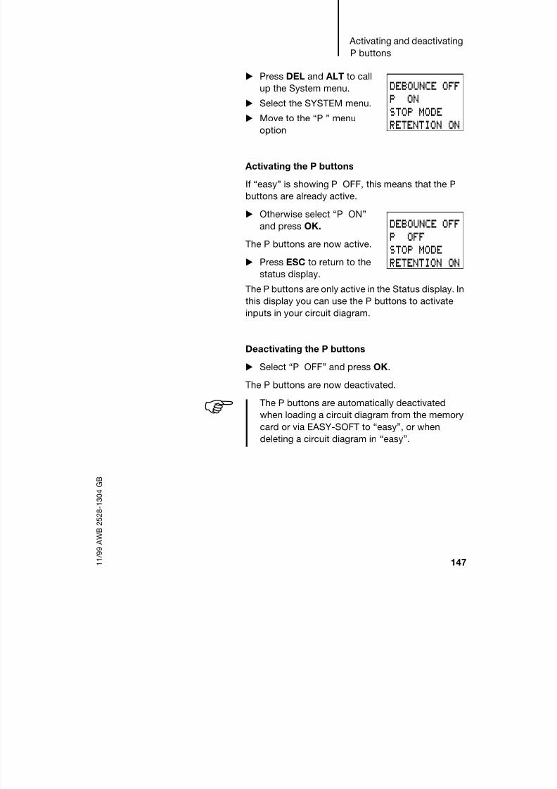
8/6/2019 Manual Easy 600
http://slidepdf.com/reader/full/manual-easy-600 150/229
Activating and deactivating
P buttons
147 1 1 / 9 9 A W B 2 5 2 8 - 1 3 0 4 G B
Press DEL and ALT to call
up the System menu.
Select the SYSTEM menu. Move to the “P ” menu
option
Activating the P buttons
If “easy” is showing P OFF, this means that the P
buttons are already active.
Otherwise select “P ON”
and press OK.
The P buttons are now active.
Press ESC to return to the
status display.
The P buttons are only active in the Status display. In
this display you can use the P buttons to activate
inputs in your circuit diagram.
Deactivating the P buttons
Select “P OFF” and press OK.
The P buttons are now deactivated.
DEBOUNCE OFFP ONSTOP MODERETENTION ON
DEBOUNCE OFFP OFFSTOP MODERETENTION ON
The P buttons are automatically deactivated
when loading a circuit diagram from the memorycard or via EASY-SOFT to “easy”, or when
deleting a circuit diagram in “easy”.

8/6/2019 Manual Easy 600
http://slidepdf.com/reader/full/manual-easy-600 151/229
“easy” Settings
148 1 1 / 9 9 A W B 2 5 2 8 - 1 3 0 4 G B
Startup behaviour The startup behaviour is an important help during the
commissioning phase. The circuit diagram which
“easy” contains is not as yet fully wired up or thesystem or machine is in a state which “easy” is not
permitted to control. The outputs should not be
controlled when “easy” is switched on.
Setting the startup behaviour
Requirement: “easy” must contain a valid circuit
diagram.
Switch to the System menu.
Specify in which operating mode “easy” should
start when the power supply is switched on (seethe figure at the top of page 149).
The default setting for “easy” is for STOP MODE to
be displayed. In other words, “easy” starts in Run
mode when the power is switched on.
“easy”-X models can only be started in Run
mode.
If “easy” is protected by a password, the System
menu will not be available until “easy” is
unlocked (see the section Unlocking easy from
page 136 ).
MODE: RUN/STOP is a toggle menu. The menu
always displays the operating mode into which
you can change.

8/6/2019 Manual Easy 600
http://slidepdf.com/reader/full/manual-easy-600 152/229
Behaviour when the circuit
diagram is deleted
149 1 1 / 9 9 A W B 2 5 2 8 - 1 3 0 4 G B
Behaviour when thecircuit diagram is
deleted
The setting for the startup behaviour is an “easy” device function. When the circuit diagram is deleted
this does not result in the loss of the setting selected.
Behaviour during
uploading and
downloading to the
card or PC
When a valid circuit diagram is transferred from
“easy” to a memory card or the PC or vice versa, the
setting is still retained.
Possible faults “easy” will not start in Run mode
“easy” does not contain a circuit diagram.
You have selected MODE: STOP in the MODE
RUN/STOP menu (the menu displayed is thusMODE: RUN).
and
2
PASSWORD...SYSTEMGB D F E I..
DEBOUNCE OFFP ONSTOP MODERETENTION ON
DEBOUNCE OFFP ONRUN MODERETENTION ON
Startup behaviour Menu displayed Status of “easy” afterstartup
“easy” starts in Stopmode
RUN MODE “easy” is in Stop mode
“easy” starts in Runmode
STOP MODE “easy” is in Run mode
“easy”-X models can only be started in Run
mode.

8/6/2019 Manual Easy 600
http://slidepdf.com/reader/full/manual-easy-600 153/229
150 1 1 / 9 9 A W B 2 5 2 8 - 1 3 0 4 G B

8/6/2019 Manual Easy 600
http://slidepdf.com/reader/full/manual-easy-600 154/229
151 1 1 / 9 9 A W B 2 5 2 8 - 1 3 0 4 G B
8 Retention
It is a requirement of system and machine controllers
for operating states or actual values to have retentive
settings. What this means is that the values will be
retained safely even after the supply voltage to a
machine or system has been switched off and are
also retained until the next time the actual value is
overwritten.
Requirements Permitted “easy” models
Retentive actual values can be set with EASY 412-
DC-.. (via the SYSTEM menu) as well as EASY 600
for the following markers and function relays.
Permitted markers and function relays
It is possible to retentively store (non-volatile
memory) the actual values (status) of markers, timing
relays and up/down counters.
The following markers and function relays can be set
to have retentive actual values:
EASY 412-DC-..
Marker relays M13, M14, M15, M16
Timing relay T8
Up/down counter C8
EASY 600
Markers M13, M14, M15, M16
Text function relays D1 to D8
Timing relays T7, T8
Up/down counters C5, C6, C7, C8

8/6/2019 Manual Easy 600
http://slidepdf.com/reader/full/manual-easy-600 155/229
Retention
152 1 1 / 9 9 A W B 2 5 2 8 - 1 3 0 4 G B
Setting retention Requirement: in this case “easy” must be in Stop
mode
Switch to the System menu.
Switch on the Retention function (see figure on
page 153 above).
The default setting of “easy” as it is supplied is the
display RETENTION ON. With this setting “easy”
runs without retentive actual value data, when a validcircuit diagram is present. When “easy” is in Stop
mode or has been switched to a de-energized state,
all actual values are cleared.
The Retention setting always applies to all of the
relays listed. Individual markers or function relays
cannot be set retentively.The retentive data of “easy”-X models with a
fitted memory card is deleted when the power
supply is switched on.
Note
The retentive data is kept every time the power
supply is switched off. Data security is assured
for 100 000 write cycles.
If “easy” is protected by a password, the System
menu will not be available until “easy” is
unlocked (see chapter 7 from page 136).
The menu item RETENTION ON/OFF is a toggle
menu. The menu always displays the operating
mode into which you can change.

8/6/2019 Manual Easy 600
http://slidepdf.com/reader/full/manual-easy-600 156/229
Deleting retentive actual
values
153 1 1 / 9 9 A W B 2 5 2 8 - 1 3 0 4 G B
Deleting retentive
actual values
The retentive actual values are cleared if the
following is fulfilled (applies only to Stop mode):
When the circuit diagram is transferred from
EASY-SOFT (PC) or from the memory card to
“easy”, the retentive actual values are reset to 0
(marker = off). This also applies when there is noprogram on the memory card. In this case the old
circuit diagram is retained in “easy”.
When there is a changeover from retention
activated (the display shows RETENTION OFF) to
retention deactivated (the display shows
RETENTION ON).
When the circuit diagram is deleted via the
DELETE PROG menu.
and
3
Retentivebehaviour
Menu displayed Behaviour: M13, M14, M15, M16, C8, T8,(D1 to D8, C5, C6, C7, T7) when the unitis switched off and on again
No retentive actualvalues
RETENTION ON All actual values will be cleared when the unitchanges from Run to Stop mode or when thepower supply is switched off.
Retentive actual values RETENTION OFF All actual values will be safely stored whenthe unit changes from Run to Stop mode orwhen the power supply is switched off. They
can then be used or deleted.
PASSWORD...SYSTEMGB D F E I..
DEBOUNCE OFFP ONSTOP MODERETENTION ON
DEBOUNCE OFFP ONRUN MODERETENTION

8/6/2019 Manual Easy 600
http://slidepdf.com/reader/full/manual-easy-600 157/229

8/6/2019 Manual Easy 600
http://slidepdf.com/reader/full/manual-easy-600 158/229
Transfer retentive behaviour
155 1 1 / 9 9 A W B 2 5 2 8 - 1 3 0 4 G B
Changing the operating mode or the circuit
diagram
When the operating mode is changed or the “easy” circuit diagram is modified, the retentive data is
normally saved together with their actual values. The
actual values of relays no longer being used are also
retained.
Changing the operating mode
If you change from Run to Stop and then back to
Run, the actual values of the retentive data will be
retained.
Modifying the “easy” circuit diagram
If a modification is made to the “easy” circuit
diagram, the actual values will be retained.
Changing the startup behaviour in the SYSTEMmenu
The retentive actual values in “easy” will be retained
irrespective of the MODE RUN or MODE STOP
settings.
Note
Even when the retentive relays M13, M14, M15,
M16 (D1 to D8) and the function relays C8, T8
(C5, C6, C7, T7) are deleted from the circuit
diagram, the retentive actual values will be
retained after the changeover from Stop to Run
as well as after the power supply is switched off
and on. Should these relays be used again in the
circuit diagram, they will still have their former
actual values.

8/6/2019 Manual Easy 600
http://slidepdf.com/reader/full/manual-easy-600 159/229
Retention
156 1 1 / 9 9 A W B 2 5 2 8 - 1 3 0 4 G B
Retentive auxiliary
relays (markers)
How the retention works
The retentive markers M13, M14, M15, M16,
D1 to D8 should be used in conjunction with thefollowing coil functions.
Set S M.., D..
Impulse relay äM.., D..
Reset R M.., D..
It is essential that you note the following points:
Due to the operation of “easy” the make contact will
remain closed and the break contact will remain
open. If the Reset condition is active when the power
supply is switched on, the state of the contact before
power on will be retained for one cycle.
This behaviour can result in a flicker effect in a lampor a solenoid valve.
Be sure to pay close attention to the example circuits
for the individual coil functions.
The following coil functions are not permitted:
ÄM13 to ÄM16, ÄD1 to ÄD8
Examples
S/R coil (break contact)
Task:
In your application you need to remember whether a
screw has been inserted or not. When your
installation switches on, it is important that a screw
which has already been screwed in place is not
screwed in again - otherwise there could be
permanent damage to the workpiece or the
production line even shut down.
Note
When the condition for resetting the marker is
fulfilled, the marker is reset.
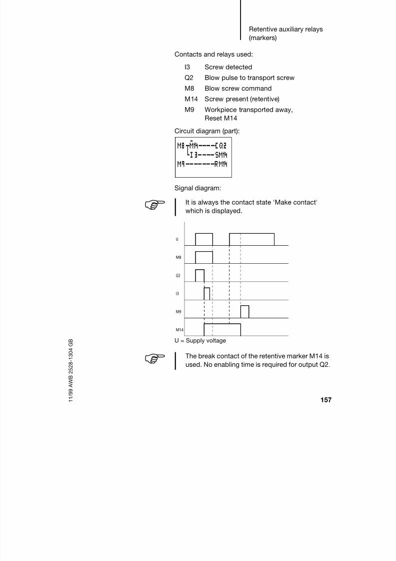
8/6/2019 Manual Easy 600
http://slidepdf.com/reader/full/manual-easy-600 160/229
Retentive auxiliary relays
(markers)
157 1 1 / 9 9 A W B 2 5 2 8 - 1 3 0 4 G B
Contacts and relays used:
I3 Screw detected
Q2 Blow pulse to transport screw
M8 Blow screw command
M14 Screw present (retentive)
M9 Workpiece transported away,
Reset M14
Circuit diagram (part):
Signal diagram:
U = Supply voltage
M8um14----ÄQ2hI3----SM14
M9-------RM14
It is always the contact state 'Make contact'
which is displayed.
U
M8
Q2
I3
M9
M14
The break contact of the retentive marker M14 is
used. No enabling time is required for output Q2.

8/6/2019 Manual Easy 600
http://slidepdf.com/reader/full/manual-easy-600 161/229
Retention
158 1 1 / 9 9 A W B 2 5 2 8 - 1 3 0 4 G B
Impulse relay
Task:
After a power failure the lights in a stairwell shouldresume their previous switching state.
Contacts and relays used:
T2 Enable after first cycle
I1 Push-button actuator
Q1 Lamp output
M15 Impulse relay (retentive)
Signal diagram:
U = Supply voltage
Circuit diagram: Parameter display:
---------TT2I1-------äM15M15-T2----ÄQ1
X f gS n00.10nÄ sTRG dT2
yRES b +
U
I1
M15
Q1
T2
t t t
A B C

8/6/2019 Manual Easy 600
http://slidepdf.com/reader/full/manual-easy-600 162/229
Retentive auxiliary relays
(markers)
159 1 1 / 9 9 A W B 2 5 2 8 - 1 3 0 4 G B
Range A:
Q1 is switched on. The power supply is switched off.
I1 is switched off. After the I1 is switched on, M15 isswitched on and remains on. If the switching of I1
would switch off M15, the opposite would apply in
the same way, and M15 would remain switched off.
Range B:
The power supply is switched off. I1 is switched on.
After the switch on in the first “easy” cycle M15 is on.
The fact that M15 and T2 are connected in series
(enable time) prevents a flickering pulse on Q1.
Range:
M15 is switched on and remains set until the next
time I1 switches on.

8/6/2019 Manual Easy 600
http://slidepdf.com/reader/full/manual-easy-600 163/229
Retention
160 1 1 / 9 9 A W B 2 5 2 8 - 1 3 0 4 G B
S/R function
Task:
After a power failure the lights in a stairwell shouldresume their previous switching state.
Contacts and relays used:
T2 Enable after first cycle
I1 Push-button actuator
M1 Push-button actuator pulse
(rising edge detection)
M2 Pulse limitation (one cycle)Q1 Lamp output
M15 Impulse relay (retentive)
Circuit diagram: Parameter display:
---------TT2I1um2----ÄM1h------ÄM2
M1-m15----SM15M1-M15----RM15M15-T2----ÄQ1
X f gS n00.10nÄ sTRG dT2
yRES b +

8/6/2019 Manual Easy 600
http://slidepdf.com/reader/full/manual-easy-600 164/229
Retentive timing relays
161 1 1 / 9 9 A W B 2 5 2 8 - 1 3 0 4 G B
Signal diagram:
U = Supply voltage
The circuit above functions in the same way as an
impulse relay switch. The make contact will remain
switched on in the first “easy” cycle ifa coil is actuated by the make contact of a
retentive marker (series and parallel connection
both apply here too) and
when the power is switched on, the reset
condition for this retentive marker is on.
The enable time T2 prevents Q1 from flickering.
Retentive timing relays How the retention works
The retentive timing relays T7, T8 can be operated
retentively in all six different switching functions. The
retention setting only makes sense under certain
conditions for the switching functions. These can be
subdivided into groups 1 and 2.
I1
M1
M15
Q1
T2
t
U

8/6/2019 Manual Easy 600
http://slidepdf.com/reader/full/manual-easy-600 165/229
Retention
162 1 1 / 9 9 A W B 2 5 2 8 - 1 3 0 4 G B
If these conditions are not fulfilled, the actual value
will be cleared when the power is restored. If the R
coil is actuated, the actual value will also be cleared.
Retention with group 1
Requirement:
When the supply voltage is switched on, actuated
trigger coils TT7, TT8 retain their state '1' (switched
on) until the set time period has elapsed. This can be
implemented using retentive markers or inputsconnected to the power.
Retention with group 2
Requirement:
When the supply voltage is switched on, actuated
trigger coils TT7, TT8 retain their state '0' (switched
off) until the set time period has elapsed. This can be
implemented using retentive markers or inputs
connected to the power.
Group 1 On-delayed (example page 163 )
On-delayed switching with random
range (example page 163 )
Single-pulse (example page 168)
Flashing (example page 169 )
Group 2 Off-delayed (example page 166)
Off-delayed switching with random time
range (example page 166 )
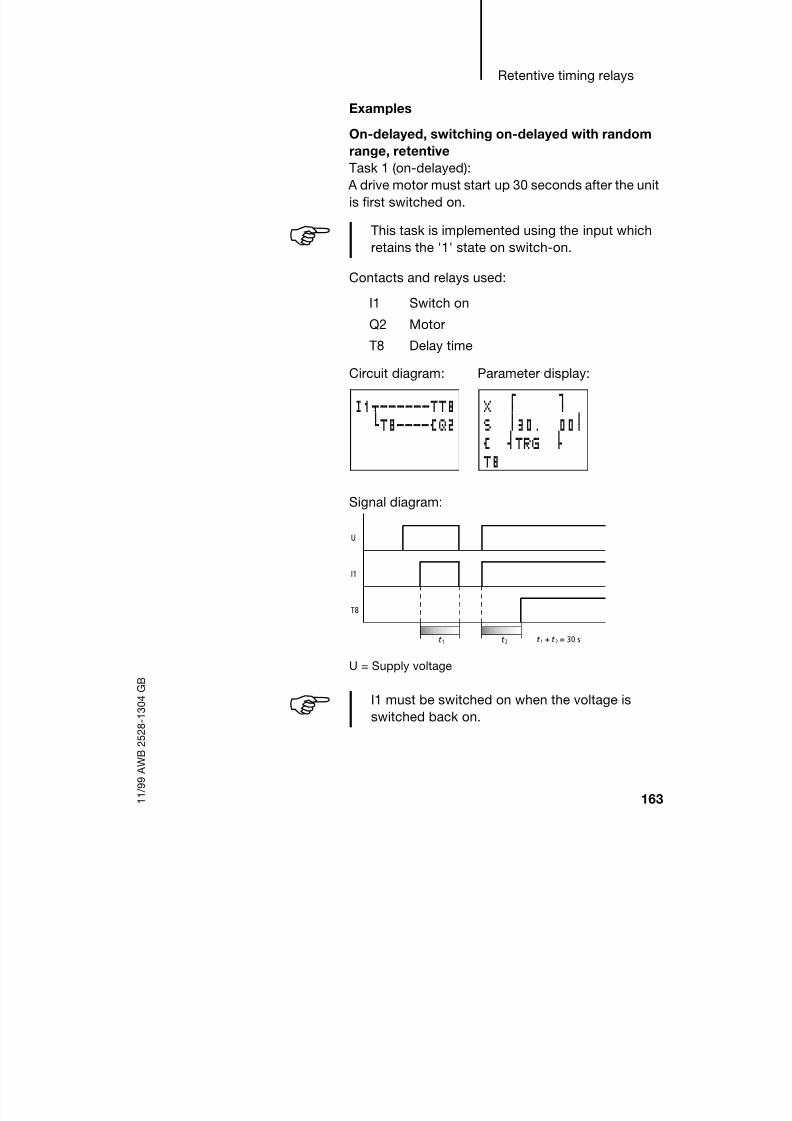
8/6/2019 Manual Easy 600
http://slidepdf.com/reader/full/manual-easy-600 166/229
Retentive timing relays
163 1 1 / 9 9 A W B 2 5 2 8 - 1 3 0 4 G B
Examples
On-delayed, switching on-delayed with random
range, retentiveTask 1 (on-delayed):
A drive motor must start up 30 seconds after the unit
is first switched on.
Contacts and relays used:
I1 Switch on
Q2 Motor
T8 Delay time
Signal diagram:
U = Supply voltage
This task is implemented using the input which
retains the '1' state on switch-on.
Circuit diagram: Parameter display:
I1u------TT8hT8----ÄQ2
X f gS n30. 00n
Ä sTRG dT8
U
I1
T8
t 1 t 2 t +1 t = 30 s2
I1 must be switched on when the voltage is
switched back on.

8/6/2019 Manual Easy 600
http://slidepdf.com/reader/full/manual-easy-600 167/229
Retention
164 1 1 / 9 9 A W B 2 5 2 8 - 1 3 0 4 G B
Task 2
A conveyor belt is to be run empty. This no-load
running is implemented by using a time relay to keepthe belt running following the STOP BELT command
until the preset time has elapsed. If this procedure is
interrupted by an interruption to the power supply,
the belt is only permitted to run empty after switch-
on for the remainder of the preset time period.
Contacts and relays used:
T6/T7 Single pulse timers
I2 Start conveyor belt
Q1 Conveyor belt motor
I3 Stop conveyor belt
M16 Stop selected
T8 Remaining time
I2 and I3 are converted to cycle pulses by T6 / T7.
Only the pressing of the push-button actuators is
This task is implemented using retentive
markers.
Circuit diagram: Parameters entered:
Setting T6, T7 ü Time:
00.00 s
I2-------TT6T6u------SQ1M16ki3-------TT7T7-------SM16M16-------TT8T8------uRQ1£
hRM16
X f gS n30. 00nÄ sTRG dT8

8/6/2019 Manual Easy 600
http://slidepdf.com/reader/full/manual-easy-600 168/229
Retentive timing relays
165 1 1 / 9 9 A W B 2 5 2 8 - 1 3 0 4 G B
recognized. Should they remain constantly
depressed, malfunctions would ensue.
Signal diagram:
U = Supply voltage
The make contact of T8 closes for one “easy” cycle
and resets M16, Q1.
In the above example T7 does not have to beretentive.
U
I2/T6
Q1
I3
M16
T8
t 1 t 2 t +1 t = 30 s2

8/6/2019 Manual Easy 600
http://slidepdf.com/reader/full/manual-easy-600 169/229
Retention
166 1 1 / 9 9 A W B 2 5 2 8 - 1 3 0 4 G B
Off-delayed, off-delayed switching with random
time range, retentive
Task:No-load running of a conveyor belt.
Contacts and relays used:
T6/T7 Single pulse timers
I2 Start conveyor belt
Q1 Conveyor belt motor
I3 Stop conveyor belt
M16 Stop selected
T8 Remaining time
I2 and I3 are converted to single pulses by T6 / T7.
Only the pressing of the push-button actuators is
recognized. Should they remain constantlydepressed, malfunctions would ensue.
Circuit diagram: Parameters entered:
Setting T6, T7 ü Time:
00.00 s
I2-------TT6T6uT8----SQ1M16k
i3-------TT7T7-------SM16M16-------TT8T8------uRQ1£
hRM16
â f gS n30. 00nÄ sTRG d
T8
In the above example T7 does not have to be
retentive.

8/6/2019 Manual Easy 600
http://slidepdf.com/reader/full/manual-easy-600 170/229
Retentive timing relays
167 1 1 / 9 9 A W B 2 5 2 8 - 1 3 0 4 G B
Signal diagram:
U = Supply voltage
U
I2/T6
Q1
I3
M16
t 1 t 2
T8
t +1 t = 30 s2

8/6/2019 Manual Easy 600
http://slidepdf.com/reader/full/manual-easy-600 171/229
Retention
168 1 1 / 9 9 A W B 2 5 2 8 - 1 3 0 4 G B
Single-pulse timing relays, retentive
Single-pulse timing relays are suitable for metering
adhesives, liquids etc.
Task: A lubricating device is to dispense at all times
a constant quantity of oil.
Contacts and relays used:
I1 Start lubrication
Q1 Oil valve
T8 Oil time
Signal diagram:
U = Supply voltage
Range: In this case the power supply is interrupted.
When the power supply is restored, the remaining
pulse time runs on until finished.
Range B: The time period runs down in this range
without interruption.
Circuit diagram: Parameters entered:
I1-------TT8T8-------ÄQ1
ü f gS n30.00nÄ sTRGd T8
U
I1
T8
t 1 t 2
Q1
t
A B
t +1 t = 30 s2

8/6/2019 Manual Easy 600
http://slidepdf.com/reader/full/manual-easy-600 172/229
Retentive timing relays
169 1 1 / 9 9 A W B 2 5 2 8 - 1 3 0 4 G B
Flashing switch operation,retentive
Task:
A flasher function is used to lower an ink stamp atidentical time intervals to print an area and then to
raise the stamp for areas where no printing is
required.
Contacts and relays used:
Q1 Valve
T8 Time
Signal diagram:
U = Supply voltage
Range A:
In this case the power supply is interrupted.
Following another switch-on, the remaining time runs
on until finished.
Circuit diagram: Parameters entered:
---------TT8T8-------ÄQ1
Ü f gS n10. 00nÄ sTRGd T8
T8
Q1
U
t t 1 t 2 t
At + t = t 1 2

8/6/2019 Manual Easy 600
http://slidepdf.com/reader/full/manual-easy-600 173/229

8/6/2019 Manual Easy 600
http://slidepdf.com/reader/full/manual-easy-600 174/229
Retentive Up/down
counters C7, C8
171 1 1 / 9 9 A W B 2 5 2 8 - 1 3 0 4 G B
Operating hours counter for maintenance
intervals
Task 2Every 1000 hours the system or machine must be
checked for possible defects. Filters and
transmission oil must be changed and the bearings
lubricated.
Contacts and relays used:
T8 Clock pulse
M16 Block double pulse
Q4 Warning light, 1000 h reached
C8 Up counter
I1 Reset
Function of the “easy” circuit diagram:
T8 provides the clock pulse. When a time of
t = 30 min. is selected the counting period amounts
to 2 t = 60 min. Every hour one impulse is counted.
The up counter C8 triggers a warning message at
1000 by means of Q4.
For the clock pulse to be correct when there is a
power outage, T8 must be retentive.
Circuit diagram: Parameters entered:
---------TT8T8um16----CC8
h------SM16t8-------RM16C8-------ÄQ4I1------uRC8
hRT8
Ü f18:38gM:Sn30.00n
Ä sTRGd T8
f1000g0107sDIR n
Ä sCNT dC8Ä yRES b +
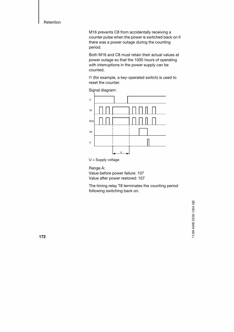
8/6/2019 Manual Easy 600
http://slidepdf.com/reader/full/manual-easy-600 175/229
Retention
172 1 1 / 9 9 A W B 2 5 2 8 - 1 3 0 4 G B
M16 prevents C8 from accidentally receiving a
counter pulse when the power is switched back on if
there was a power outage during the countingperiod.
Both M16 and C8 must retain their actual values at
power outage so that the 1000 hours of operating
with interruptions in the power supply can be
counted.
I1 (for example, a key-operated switch) is used to
reset the counter.
Signal diagram:
U = Supply voltage
Range A:
Value before power failure: 107
Value after power restored: 107
The timing relay T8 terminates the counting period
following switching back on.
U
T8
M16
Q4
I1
A

8/6/2019 Manual Easy 600
http://slidepdf.com/reader/full/manual-easy-600 176/229
Retentive Up/down
counters C7, C8
173 1 1 / 9 9 A W B 2 5 2 8 - 1 3 0 4 G B
Automatic lubrication at constant intervals and
with a constant quantity of lubricant
Task 3:60 minutes after the last lubrication the bearings of a
machine must be lubricated for 30 seconds.
Contacts and relays used:
T1 Clock pulse
M15 Lubricate
Q1 Valve
T8 Lubrication timeC8 Up counter
Circuit diagram: Parameters entered:
Parameter display:
Parameters entered:
---------TT1T1-m15----CC8C8-------SM15M15------uTT8
hRC8M15-t8----ÄQ1T8-------RM15
Ü f gS n00.50nÄ sTRG dTI
yRES b +
f3600 gsDIR n
Ä sCNT dC8Ä yRES b +
X f gS n30.00nÄ sTRGd T8

8/6/2019 Manual Easy 600
http://slidepdf.com/reader/full/manual-easy-600 177/229
Retention
174 1 1 / 9 9 A W B 2 5 2 8 - 1 3 0 4 G B
Function of the “easy” circuit diagram:
T1 provides the clock pulse. When a time of
t = 0.5 seconds is selected the counting periodamounts to 2 t = 1 s. One impulse is counted every
second.
The up counter C8 switches valve Q1 on via M15 at
3600 counting pulses (3600 s = 1 h).
M15 resets C8 and prepares C8 for the next hour. To
stop C8 continuing to count, the break contact of
M15 blocks the counting pulses.
T8 is actuated by means of M15. Once T8 has timed
out, M15 and T8 will be reset.
In order that both the time elapsed since the last
lubrication (counter C8) and also the lubrication
pulse remains constant in the event of a power
outage, C8, M15 and T8 must be retentive.
Signal diagram:
U = Supply voltage
U
T1
C8
M15
Q1
t 1 t 2
T8
t +1 t = 30 s2

8/6/2019 Manual Easy 600
http://slidepdf.com/reader/full/manual-easy-600 178/229
175 1 1 / 9 9 A W B 2 5 2 8 - 1 3 0 4 G B
9 Inside “easy”
“easy” circuit diagram
cycle
In conventional control systems, a relay or contactor
control processes all the circuit connections in
parallel. The speed with which a contactor switches
is thus dependent on the components used, and
ranges from 15 to 40 ms for relay pick-up and drop-
out.
With “easy” the circuit diagram is processed with a
microprocessor that simulates the contacts andrelays of the circuit concerned and thus processes all
switching operations considerably faster. Depending
on its size, the “easy” circuit diagram is processed
cyclically every 0.5 to 40 ms.
During this time, “easy” passes through five
segments in succession.
How “easy” evaluates the circuit diagram:
In the first three segments “easy” evaluates the
contact fields in succession. As it does so, “easy”
also checks whether contacts are connected in
parallel or in series and stores the switching states of
all the contact fields.
Circuit
conne
ctions
Range
1 2 3 4 5
1
2
3
4
.. ...I1-q1-j--ÄQ8
I1-I4-Ö1-TT2I2-I3----RT2T2-u-----ÄQ1P1-kêê êêê

8/6/2019 Manual Easy 600
http://slidepdf.com/reader/full/manual-easy-600 179/229

8/6/2019 Manual Easy 600
http://slidepdf.com/reader/full/manual-easy-600 180/229
“easy” circuit diagram cycle
177 1 1 / 9 9 A W B 2 5 2 8 - 1 3 0 4 G B
Example: Switching one cycle later
This is the circuit diagram of a
self-latching circuit. If I1 and I2are closed, the switching state
of relay coil ÄQ1 is “latched” via
contact Q1.
1st cycle: I1 and I2 are
switched on. Coil ÄQ1 picks
up.
Contact Q1 remains
switched off since “easy” evaluates from left to right.
2nd cycle: The self-latching function now
becomes active. “easy” has transferred the coil
states to contact Q1 at the end of the first cycle.
Example: Do not wire backwards
This example is shown in
chapter 5. It was used in the
section „Creating andmodifying connections“ to
illustrate how NOT to do it.
In the third circuit connection,
“easy” finds a connection to the second circuit
connection in which the first contact field is empty.
The output relay is not switched.
When wiring more than three
contacts in series, use one ofthe marker relays.
Circuit diagram:
Start condition:I1, I2 switched onQ1 switched off.
I1uI2----ÄQ1Q1k
I1-Q4-i3oz-----khI2-I4-ÄQ2
I1-Q4-i3-ÄM1I2-I4-M1-ÄQ2

8/6/2019 Manual Easy 600
http://slidepdf.com/reader/full/manual-easy-600 181/229
Inside “easy”
178 1 1 / 9 9 A W B 2 5 2 8 - 1 3 0 4 G B
Determining the cycle
time of “easy” circuit
diagrams
The maximum cycle time of a circuit diagram must
be known in order to determine the maximum
counter frequency or reaction time of “easy”.
EASY 412
For EASY 412 the cycle time can be calculated as
follows:
Table 1: List of times for processing function relays
Number Time durationin s
Total
Basic pulse 1 210 –
Refresh 1 3500 –
Contacts and bridged contactfields
– 20 –
Coils – 20 –
Circuit connections from thefirst one to the last one, withempty ones in between
– 50 –
Connecting lines (only
f,v,d)– 20 –
Timing relays (see Table 1) – – –
Counters (see Table 1) – – –
Analog value function relays(see Table 1)
– – –
Total –
Number 1 2 3 4 5 6 7 8
Timing relays in s 20 40 80 120 160 200 240 280
Counters in s 20 50 90 130 170 210 260 310
Analog valueprocessors in s
80 100 120 140 160 180 220 260

8/6/2019 Manual Easy 600
http://slidepdf.com/reader/full/manual-easy-600 182/229
Determining the cycle time
of “easy” circuit diagrams
179 1 1 / 9 9 A W B 2 5 2 8 - 1 3 0 4 G B
Example 1: parallel circuit
Calculation of the maximum
cycle time for the followingcircuit diagram:
Number Time durationin s
Total
Basic pulse 1 210 210
Refresh 1 3500 3500
Contacts and bridged contactfields
4 20 80
Coils 1 20 20
Circuit connections from thefirst one to the last one, withempty ones in between
2 50 100
Connecting lines (only f,v,d)
– 20 –
Timing relays (see Table 1) – – –
Counters (see Table 1) – – –
Analog value function relays(see Table 1)
– – –
Total 3910
I2u------ÄQ4I3k

8/6/2019 Manual Easy 600
http://slidepdf.com/reader/full/manual-easy-600 183/229
Inside “easy”
180 1 1 / 9 9 A W B 2 5 2 8 - 1 3 0 4 G B
Example 2: Star/delta drive
Number Time durationin s
Total
Basic pulse 1 210 210
Refresh 1 3500 3500
Contacts and bridged contactfields
9 20 180
Coils 4 20 80
Circuit connections from thefirst one to the last one, withempty ones in between
4 50 200
Connecting lines (only f,v,d)
3 20 60
Timing relays (see Table 1) 2 40 40
Counters (see Table 1) – – –
Analog value function relays(see Table 1)
– – –
Total 4270
I1u------TT1
dt1----ÄQ1dT1----TT2hT2----ÄQ2

8/6/2019 Manual Easy 600
http://slidepdf.com/reader/full/manual-easy-600 184/229
Determining the cycle time
of “easy” circuit diagrams
181 1 1 / 9 9 A W B 2 5 2 8 - 1 3 0 4 G B
Example 3: operating hours counter
Number Time durationin s
Total
Basic pulse 1 210 210
Refresh 1 3500 3500
Contacts and bridged contactfields
17 20 340
Coils 7 20 140
Circuit connections from thefirst one to the last one, withempty ones in between
7 50 350
Connecting lines (only f,v,d)
2 20 40
Timing relays (see Table 1) 1 20 20
Counters (see Table 1) 1 20 20
Analog value function relays(see Table 1)
– – –
Total 4620
---------TT8T8um16----CC8h------SM16
t8-------RM16C8-------ÄQ4I1------uRC8
hRT8

8/6/2019 Manual Easy 600
http://slidepdf.com/reader/full/manual-easy-600 185/229
Inside “easy”
182 1 1 / 9 9 A W B 2 5 2 8 - 1 3 0 4 G B
EASY 600
For EASY 600 the cycle time can be calculated as
follows:
Table 2: List of times for processing function relays
Number Time durationin s
Total
Basic pulse 1 520 –
Refresh – 5700 –
Contacts and bridged contactfields
– 40 –
Coils – 20 –
Circuit connections from thefirst one to the last one, withempty ones in between
– 70 –
Connecting lines (only f,v,d)
– 40 –
Timing relays (see Table 2) – – –
Counters (see Table 2) – – –
Analog value function relays(see Table 2)
– – –
Total –
Number 1 2 3 4 5 6 7 8
Timing relays in s 40 120 160 220 300 370 440 540
Counters in s 40 100 160 230 300 380 460 560
Analog value
processors in s
120 180 220 260 300 360 420 500

8/6/2019 Manual Easy 600
http://slidepdf.com/reader/full/manual-easy-600 186/229

8/6/2019 Manual Easy 600
http://slidepdf.com/reader/full/manual-easy-600 187/229
Inside “easy”
184 1 1 / 9 9 A W B 2 5 2 8 - 1 3 0 4 G B
Delay times for inputs
and outputs
The time from reading the inputs
and outputs to switching
contacts in the circuit diagramcan be determined in “easy” by
delay time.
This function is useful, for
example, in order to ensure a
clean switching signal despite
contact bounce.
“easy”-DC and “easy”-AC units function with
different input voltages and therefore also havedifferent evaluation methods and delay times.
Debounce delay times for basic “easy”-DC basic
units
The debounce for DC signals is 20 ms.
An input signal S1 must therefore be 15 V for at least
20 ms on the input terminal before the switch contact
will change from 0 to 1 (A). If applicable, this time
must also include the cycle time (B) since “easy”
does not detect the signal until the start of a cycle.
The same debounce delay (C) applies when the
signal drops out from 1 to 0.
S1
0V I1
1
0
1
0
S1
B
A
B
C

8/6/2019 Manual Easy 600
http://slidepdf.com/reader/full/manual-easy-600 188/229
Delay times for inputs and
outputs
185 1 1 / 9 9 A W B 2 5 2 8 - 1 3 0 4 G B
If the debounce is switched off, “easy” responds to
an input signal after just 0.25 ms.
Typical delay times with the debounce delay
switched off are:
On-delay for
I1 to I12: 0.25 ms
Off-delay for
I1 to I6 and I9 to I12: 0.4 ms
I7 and I8: 0.2 ms
Debounce delay times for “easy”-AC basic units
The input debounce with AC voltage signals
depends on the frequency:
Switch-on delay
80 ms at 50 Hz, 66 ms at 60 Hz.
Off-delay forI1 to I6 and I9 to I12: 80 ms (66 ms)
I7 and I8: 160 ms (150 ms) with EASY 412-AC
I7 and I8: 80 ms (66 ms) with EASY 6..-AC
1
0
1
0
S1
B
A C
B
Check that there is no interference affecting the
input signals when the debounce delay is
switched off. “easy” will respond even to veryshort signals.
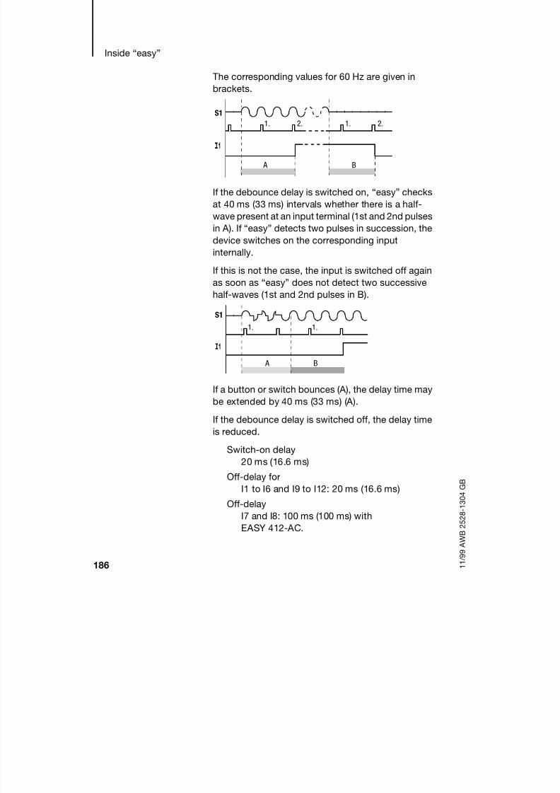
8/6/2019 Manual Easy 600
http://slidepdf.com/reader/full/manual-easy-600 189/229
Inside “easy”
186 1 1 / 9 9 A W B 2 5 2 8 - 1 3 0 4 G B
The corresponding values for 60 Hz are given in
brackets.
If the debounce delay is switched on, “easy” checks
at 40 ms (33 ms) intervals whether there is a half-
wave present at an input terminal (1st and 2nd pulses
in A). If “easy” detects two pulses in succession, the
device switches on the corresponding input
internally.
If this is not the case, the input is switched off again
as soon as “easy” does not detect two successive
half-waves (1st and 2nd pulses in B).
If a button or switch bounces (A), the delay time may
be extended by 40 ms (33 ms) (A).
If the debounce delay is switched off, the delay timeis reduced.
Switch-on delay
20 ms (16.6 ms)
Off-delay for
I1 to I6 and I9 to I12: 20 ms (16.6 ms)
Off-delay
I7 and I8: 100 ms (100 ms) with
EASY 412-AC.
A
2.1. 2.1.
B
S1
1. 1.
S1
A B

8/6/2019 Manual Easy 600
http://slidepdf.com/reader/full/manual-easy-600 190/229

8/6/2019 Manual Easy 600
http://slidepdf.com/reader/full/manual-easy-600 191/229
Inside “easy”
188 1 1 / 9 9 A W B 2 5 2 8 - 1 3 0 4 G B
Transfer EASY-TC-DC ©©©©Memory card ©©©©
EASY..-..-R...:
I16 is added during transfer of the circuit diagraminto “easy” from the memory card. I16 appears as I16
and the logical state remains '0' = switched off (make
contact).
If I16 is changed in any way, only I1 to I8 can be
entered. I16 can be deleted with the DEL button.
Transfer EASY-DC-TC ©©©© EASY-SOFT (PC)
EASY-SOFT, Version 1.0, cannot process input I16.
I16 is deleted during the transfer to EASY-SOFT.
EASY-SOFT, Version 1.1, tolerates I16 without
editing being possible. I16 is transferred when the
circuit diagram is downloaded.
I16 should be evaluated in accordance with the
individual application.
The following examples are for I16 = Q1 to Q4. I15
indicates in the same way short-circuits and
overloads on Q5 to Q8.
Example 1: Output with fault indication
The above circuit diagram functions as follows:
If a transistor output reports a fault, M16 is set by I16.
The break contact of M16 switches off output Q1.
M16 can be cleared by resetting the “easy” powersupply.
I15, I16 can only be edited with “easy” versions
which have transistor outputs.
I1-m16----ÄQ1I16-------SM16êê êê êê êêêêê êê êê êêê

8/6/2019 Manual Easy 600
http://slidepdf.com/reader/full/manual-easy-600 192/229
Short-circuit/overload
monitoring with
EASY..-DC-T..
189 1 1 / 9 9 A W B 2 5 2 8 - 1 3 0 4 G B
Example 2: Output of operating state
The above circuit functions as described in
Example 1. An additional feature is that when an
overload is detected the indicator light at Q4 is
actuated. If Q4 has an overload, it would 'pulse'.
Example 3: Automatic reset of error signal
The above circuit diagram functions in the same way
as Example 2. In addition the marker M16 is resetevery 60 seconds by timing relay T8 (on-delayed,
60 s). Should I16 remain in state '1', M16 will
continue to be set. Q1 is set briefly to '1' until I16
switches off again.
I1-m16----ÄQ1I16-------SM16M16-------ÄQ4êê êê êê êêê
I1-m16----ÄQ1I16-------SM16M16-------TT8T8-------RM16M16-------ÄQ4

8/6/2019 Manual Easy 600
http://slidepdf.com/reader/full/manual-easy-600 193/229
Inside “easy”
190 1 1 / 9 9 A W B 2 5 2 8 - 1 3 0 4 G B
Expanding EASY 600 You can expand “easy” models EASY 619/621-...
locally using the expansion units EASY 618-AC-RE
or EASY 620-DC-TE or remotely – using theEASY 200-EASY coupling module.
For this first install the units and connect the inputs
and outputs (see chapter 3, Installation).
Incorporate the inputs of the expansion units as
contacts in the “easy” circuit diagram like the inputs
in the basic unit. The input contacts possible are R1
to R12.
R15, R16 are the central fault inputs of the transistor
expansion unit (see also Scanning Short-circuit/
Overload on page 187 ).
The outputs are processed as relay coils or contacts
like the outputs in the basic unit. The output relays
are S1 to S8.
How is an expansion unit recognised?
When using at least one R contact or S contact/coil
in the circuit diagram, the basic unit assumes that an
expansion unit is connected.
Transfer behaviour
The input and output data of the expansion units is
transferred serially in both directions. Take into
account the modified reaction times of the inputs and
outputs of the expansion units:
EASY 618-AC-RE provides the outputs S1 to S6.
The other outputs S7, S8 can be used asmarkers.

8/6/2019 Manual Easy 600
http://slidepdf.com/reader/full/manual-easy-600 194/229
Expanding EASY 600
191 1 1 / 9 9 A W B 2 5 2 8 - 1 3 0 4 G B
Input and output reaction times of expansion
units
The debounce setting has no effect on the expansionunit.
Transfer times for input and output signals:
Local expansion
Time for inputs R1 to R12:
30 ms + 1 cycle
Time for outputs S1 to S6 (S8):
15 ms + 1 cycle
Remote expansion
Time for inputs R1 to R12:
80 ms + 1 cycle
Time for outputs S1 to S6 (S8):
40 ms + 1 cycle
Function monitoring of expansion units
If the power supply of the expansion unit is not
present, no connection can be established between
it and basic unit. The expansion inputs R1 to R12,
R15, R16 are incorrectly processed in the basic unit
and show status 0. It cannot be assured that the
outputs S1 to S8 are transferred to the expansion
unit.
The status of the internal input I14 of the basic unit
indicates the status of the expansion unit:
I14 = “0”: Expansion unit is functional
I14 = “1”: Expansion unit is not functional
Warning
Ensure the continuous monitoring of the “easy”
expansion in order to prevent switching faults in
machines or systems.

8/6/2019 Manual Easy 600
http://slidepdf.com/reader/full/manual-easy-600 195/229
Inside “easy”
192 1 1 / 9 9 A W B 2 5 2 8 - 1 3 0 4 G B
Example
Power can be applied to the expansion unit later than
the basic unit. This therefore means that the basicunit is switched to Run with the expansion unit
missing. The “easy” circuit diagram below detects if
the expansion unit is operational or not.
As long as I14 is 1, the remaining circuit diagram is
skipped. If I14 is 0, the circuit diagram is processed.
If the expansion unit drops out for any reason, the
circuit diagram is skipped. M1 detects whether the
circuit diagram was processed for at least one cycle
after the power supply is switched on. If the circuit
diagram is skipped, all the outputs retain theirprevious state. The next example should be used if
this is not desired.
Example with LCD output and reset of the outputs
I14-m1----Ä:8---------SM1I14--------Ä:8I1uI2----ÄQ1
Q1k
I14-m1----Ä:1---------SM1I14--------Ä:1
I2uI3----ÄQ1Q1kI14-------ÄD1I14--------Ä:8:8------uÄD1
hRQ1:8

8/6/2019 Manual Easy 600
http://slidepdf.com/reader/full/manual-easy-600 196/229
193 1 1 / 9 9 A W B 2 5 2 8 - 1 3 0 4 G B
10 What Happens If ...?
You may sometimes find that “easy” does not do
exactly what you expect. If this happens, read
through the following notes which are intended to
help you solve some of the problems you may
encounter.
You can use the power flow display in “easy” to
check the logic operations in the “easy” circuit
diagrams with reference to the switching states ofcontacts and relays.
Only qualified persons should test “easy” voltages
while the device is in operation.

8/6/2019 Manual Easy 600
http://slidepdf.com/reader/full/manual-easy-600 197/229
What Happens If ...?
194 1 1 / 9 9 A W B 2 5 2 8 - 1 3 0 4 G B
Messages from the “easy” system
“easy” systemmessages on the LCD
Explanation Remedy
No display Power supply interrupted Switch on the power supply
“easy” LCD faulty Replace “easy”
Continuous display
“TEST: AC” Self-test aborted Replace “easy”
“TEST: EEPROM”
“TEST: DISPLAY”
“TEST: CLOCK”
“ERROR: I2C” Memory card removed or not insertedcorrectly before saving
Insert memory card
Memory card faulty Replace memory card
“easy” is faulty Replace “easy”
“ERROR: EEPROM” The memory for storing the retentive values orthe “easy” circuit diagram memory is faulty.
Replace “easy”
“ERROR: CLOCK” Clock error Replace “easy”
“ERROR: LCD” LCD is faulty Replace “easy”
“ERROR: ACLOW” Incorrect AC voltage Test the voltage
“easy” is faulty Replace “easy”

8/6/2019 Manual Easy 600
http://slidepdf.com/reader/full/manual-easy-600 198/229
Possible situations when
creating circuit diagrams
195 1 1 / 9 9 A W B 2 5 2 8 - 1 3 0 4 G B
Possible situations when creating circuit diagrams
Possible situations when creatingcircuit diagrams
Explanation Remedy
Cannot enter contact or relay incircuit diagram
“easy” is in Run mode Select Stop mode
Time switch switches at wrong times Incorrect time or time switch parameters Check time andparameters
Cannot select analog comparator“Ax”
“easy” AC versions have no analoginputs
Use “easy” DC forcomparing analog values
Cannot select time switch contacts “easy” has no clock Use “easy” “-C” versions for time switchfunctions
When using a memory card “easy” will display the message “PROGINVALID”
“easy” memory card contains no circuitdiagram
Change the version of “easy” or change thecircuit diagram on thememory card
Circuit diagram on the memory card usescontacts/relays that “easy” does notrecognise:
– Use “easy”-C versions for time switchfunctions– Analog outputs only with “easy”-DC
Current flow display does not showmodifications to the circuitconnections
“easy” is in Stop mode Select Run mode
Operation / connection not performed Check the circuit diagramand parameter sets andmodify as required
Relay does not activate coil
Incorrect parameter values / time
– Analog value comparison is incorrect– Time value of timing relay is incorrect– Function of timing relay is incorrect
Relay “Q” or “M” does not pick up Relay coil has been wired up severaltimes
Check coil field entries
Input not detected Loose terminal contact Check installation
instructions, checkexternal wiringNo voltage to switch/button
Broken wire
“easy” input is faulty Replace “easy”
Relay output “Q” does not switchand activate the load
“easy” in Stop mode Select Run mode
No voltage at relay contact Check installationinstructions, checkexternal wiring
“easy” power supply interrupted
“easy” circuit diagram does not activaterelay output
Broken wire
“easy” relay is faulty Replace “easy”

8/6/2019 Manual Easy 600
http://slidepdf.com/reader/full/manual-easy-600 199/229
What Happens If ...?
196 1 1 / 9 9 A W B 2 5 2 8 - 1 3 0 4 G B
Event
Event Explanation Remedy
The actual values are not beingstored retentively.
Retention has not been switchedon.
Switch on retention in the SYSTEMmenu.
EASY 412-AC.. does not recognizethe function.
Use EASY 412-DC
EASY 412-DC.. does not recognizethe function.
Use EASY 412-DC with retention
The “easy” circuit diagram hasbeen loaded with an EASY-SOFTversion which does not support
the function.
Switch on retention in the SYSTEMmenu.
The RETENTION ON/OFF menu isnot displayed in the SYSTEM menu.
This “easy” model does not havethis function.
Use EASY 412-DC
“easy” is in Run mode Stop mode
The SYSTEM menu is not displayed. This “easy” model does not havethis menu.
Exchange “easy” if you needretention
“easy” starts only in operatingmode STOP
No circuit diagram in “easy” Load, input circuit diagram
Startup behaviour is set to thefunction “Startup in operating
mode STOP”.
Set the startup behaviour in theSYSTEM menu.
LCD display showing nothing EASY 412, EASY 600No power supply
Switch on the power supply
“easy” is faulty Press the cursor “OK” button. If no menu appears, replace the“easy”.
EASY 600Text displayed with too manyspaces
Enter text or do not select

8/6/2019 Manual Easy 600
http://slidepdf.com/reader/full/manual-easy-600 200/229

8/6/2019 Manual Easy 600
http://slidepdf.com/reader/full/manual-easy-600 201/229
Technical Data
198 1 1 / 9 9 A W B 2 5 2 8 - 1 3 0 4 G B
Figure 2: EASY Dimensions 412-... in mm
(for specifications in inches see Table 3 )
10.75 50
M4
35.75
71.5
9 0
1 0 2
1 1 0
47.5
56.5
58
4 5
4.5

8/6/2019 Manual Easy 600
http://slidepdf.com/reader/full/manual-easy-600 202/229
General
199 1 1 / 9 9 A W B 2 5 2 8 - 1 3 0 4 G B
Figure 3: EASY Dimensions 600 in mm(for specifications in inches see Table 3 )
Table 3: Dimensions in inches
9 0
1 0 2
1 1 0
M4
107.5
75 16.2516.25
47.5
56.5
58
4 5
4.5
mm inches4.5 0.1777.5 0.29510.75 4.2316.25 0.6435.5 1.435.75 1.4145 1.7747.5 1.8750 1.9756.5 2.2258 2.2871.5 2.8175 2.9590 3.54102 4.01
107.5 4.23110 4.33

8/6/2019 Manual Easy 600
http://slidepdf.com/reader/full/manual-easy-600 203/229

8/6/2019 Manual Easy 600
http://slidepdf.com/reader/full/manual-easy-600 204/229
General
201 1 1 / 9 9 A W B 2 5 2 8 - 1 3 0 4 G B
Dielectric strength
Measurement of the air clearance
and creepage distance
EN 50 178, UL 508, CSA C22.2, No 142
Dielectric strength EN 50 178
Tools and cable cross-sections
Solid min. 0.2 mm2, max. 4 mm2/AWG: 28, 12
Flexible with ferrule min. 0.2 mm2, max. 2.5 mm2/AWG: 28, 14
Slot-head screwdriver, width 3.5 0.8 mm0.14 0.03
Tightening torque 0.6 Nm
Backup/accuracy of real-time clock (only with “easy”-C)
Clock battery back-up
at 25 °C/77 °F Normally 64 h
at 40 °C/104 °F Normally 24 h
Accuracy of the real-time clock Normally 5 s/day, ~ 0.5 h/year
Repetition accuracy of timing relays
Accuracy of timing relays 1 % of value
ResolutionRange “s” 10 ms
Range “M:S” 1 s
Range “H:M” 1 min.
Retentive memory
Write cycles of the retentive memory 100 000

8/6/2019 Manual Easy 600
http://slidepdf.com/reader/full/manual-easy-600 205/229
Technical Data
202 1 1 / 9 9 A W B 2 5 2 8 - 1 3 0 4 G B
Power supply EASY 412-AC-..., EASY 618/619-AC-R..
EASY 412-DC-..., EASY 620/621-DC-TC(X),
EASY 620-DC-TE
EASY 412-AC-... EASY 618/619-AC-R..
Rated value (sinusoidal) 115/120/230/240 V AC 100/110/115/120/230/240 V AC
Operating range +10/–15 %90 to 264 V AC
+10/–15 %85 to 264 V AC
Frequency, rated value, tolerance 50/60 Hz, 5 % 50/60 Hz, 5 %
Input current consumption
at 115/120 V AC 60 Hz Normally 40 mA Normally 70 mA
at 230/240 V AC 50 Hz Normally 20 mA Normally 35 mA
Voltage dips 20 ms, EN 61131-2 20 ms, EN 61131-2Power loss
at 115/120 V AC Normally 5 VA Normally 10 VA
at 230/240 V AC Normally 5 VA Normally 10 VA
EASY 412-DC-... EASY 620/621-DC-TC(X),EASY 620-DC-TE
Rated voltage
Rated value 24 V DC, +20 %, –15 % 24 V DC, +20 %, –15 %
Permissible range 20.4 to 28.8 20.4 to 28.8
Residual ripple 5 % 5 %
Input current at 24 V DC Normally 80 mA Normally 140 mA
Voltage dips 10 ms, EN 61131-2 10 ms, EN 61131-2
Power dissipation at 24 V DC Normally 2 W Normally 5 VA

8/6/2019 Manual Easy 600
http://slidepdf.com/reader/full/manual-easy-600 206/229
Inputs
203 1 1 / 9 9 A W B 2 5 2 8 - 1 3 0 4 G B
Inputs EASY-412-AC-...,
EASY 618/619-AC-RC(X), EASY 618-AC-RE
EASY-412-AC-... EASY 618/619-AC-RC(X),EASY 618-AC-RE
Digital inputs 115/230 V AC
Number 8 12
Status display LCD (if provided) LCD (if provided)
Electrical isolation
To power supply No No
Between each other No No
to the outputs Yes Yes
Rated voltage L (sinusoidal)
0 signal 0 to 40 V AC 0 to 40 V AC
1 signal 79 to 264 V AC 79 to 264 V AC
Rated frequency 50/60 Hz 50/60 Hz
Input current with 1 signalR1 to R12, I1 to I6(EASY 618/619 also I9 to I12)
6 0.5 mA at 230 V AC 50 Hz,6 0.25 mA at 115 V AC 60 Hz
10 (12) 0.5 mA at 230 V AC,50 Hz10 (12) 0.25 mA at 115 V AC,
60 Hz
Input current on 1 signalI7, I8
2 6 mA at 230 V AC 50 Hz,2 4 mA at 115 V AC 60 Hz
2 6 mA at 230 V AC 50 Hz,2 4 mA at 115 V AC 60 Hz
Delay time for 0 to 1 and 1 to 0 for I1 to I6, I9 to I12
Debounce ON 80 ms (50 Hz), 66 ms (60 Hz) 80 ms (50 Hz), 66 ms (60 Hz)
Debounce OFF (also R1 to R12) 20 ms (50 Hz), 16 ms (60 Hz) 20 ms (50 Hz), 16 ms (60 Hz)
Delay time I7, I8 for 1 to 0
Debounce ON 160 ms (50 Hz), 150 ms (60 Hz) 80 ms (50 Hz),66 ms (60 Hz)
Debounce OFF 100 ms (50 Hz/60 Hz) 20 ms (50 Hz), 16 ms (60 Hz)
Delay time I7, I8 for 0 to 1
Debounce ON 80 ms (50 Hz), 66 ms (60 Hz) 80 ms (50 Hz), 66 ms (60 Hz)
Debounce OFF 20 ms (50 Hz), 16 ms (60 Hz) 20 ms (50 Hz), 16 ms (60 Hz)
Max. permissible cable length (per input)
I1 to I6, R1 to R12(with EASY 618/619 also I9 to I12)
Normally 40 m Normally 40 m
I7, I8 Normally 100 m Normally 100 m
2 / 3 2 / 32 / 3 2 / 3
2 / 32 / 3
2 / 3 2 / 32 / 3 2 / 3

8/6/2019 Manual Easy 600
http://slidepdf.com/reader/full/manual-easy-600 207/229
Technical Data
204 1 1 / 9 9 A W B 2 5 2 8 - 1 3 0 4 G B
EASY 412-DC-..., EASY 6..-DC-..., EASY ...-DC-.E
EASY 412-DC-... EASY 6..-DC-...,EASY...-DC-.E
Digital inputs 24 V AC
Number 8, 2 of which (I7,I8) can beused as analog inputs
12, 2 of which (I7,I8) can be usedas analog inputs
Status display LCD (if provided) LCD (if provided)
Electrical isolation
To power supply No No
Between each other No No
to the outputs Yes Yes
24 V DC power supply
Rated value 24 V DC 24 V DC
0 signal 5.0 V DC I1 to I8 5.0 V DCI1 to I12, R1 to R12
1 signal 15.0 V DC I1 to I8 15.0 V DCI1 to I12, R1 to R12
Input current on 1 signal
I1 to I6, R1 to R12(with EASY 620 also I9 to I12)
3.3 mA at 24 V DC 3.3 mA at 24 V DC
I7, I8 2.2 mA at 24 V DC 2.2 mA at 24 V DC
Delay time for 0 to 1
Debounce ON 20 ms 20 ms
Debounce OFF(I1 to I6, I9 to I12)
Normally 0.25 ms Normally 0.25 ms
Delay time for 1 to 0
Debounce ON(I1 to I6, I9 to I12)
20 ms 20 ms
Debounce OFF (also R1 to R12) Normally 0.4 ms I1 to I6Normally 0.2 ms I7, I8
Normally 0.4 ms I1 to I6, I9 to I12Normally 0.2 ms I7, I8
Cable length (unshielded) 100 m 100 m

8/6/2019 Manual Easy 600
http://slidepdf.com/reader/full/manual-easy-600 208/229
Inputs
205 1 1 / 9 9 A W B 2 5 2 8 - 1 3 0 4 G B
EASY 412-DC-... EASY 6..-DC-...
Analog inputs
Number 2 2
Electrical isolation
To power supply No No
To the digital inputs No No
to the outputs Yes Yes
Input type DC voltage DC voltage
Signal range 0 to 10 V DC 0 to 10 V DC
Resolution analog 0.1 V 0.1 VResolution digital 0.1 0.1
Input impedance 11.2 k 11.2 k
Accuracy of
Two “easy” devices 3 % of actual value 3 % of actual value
within a single device 2 % of actual value (I7, I8), 0.12 V
Conversion time, analog/digital Debounce ON: 20 msDebounce OFF: Every cycle time
Input current 1 mA 1 mA
Cable length (shielded) 30 m 30 m
U[V]
5.0
9.9
5.0 9.90

8/6/2019 Manual Easy 600
http://slidepdf.com/reader/full/manual-easy-600 209/229
Technical Data
206 1 1 / 9 9 A W B 2 5 2 8 - 1 3 0 4 G B
Relay outputs EASY 412-...-R..., EASY 618/619...
EASY 412-...-R... EASY 618/619...
Number 4 6
Type of outputs Relay Relay
In groups of 1 1
Connection of outputs in parallel toincrease the output
Not permissible Not permissible
Protection for an output relay Miniature circuit-breaker B16 or 8 A fuse (slow)
Potential isolation to mains supply,inputs
Yes300 V eff AC (safe isolation)
600 V eff AC (Basic isolation)
Yes300 V eff AC (safe isolation)
600 V eff AC (Basic isolation)
Mechanical lifespan(switching cycles)
10 106 10 106
Contacts relays
Conventional thermal current 8 A (10 A UL) 8 A (10 A UL)
Recommended for load 500 mA, 12 V AC/DC 500 mA, 12 V AC/DC
Short-circuit resistance cos = 1 16 A characteristic B (B16) at 600 A
Short-circuit resistance
cos = 0.5 to 0.7
16 A characteristic B (B16) at 900 A
Rated impulse withstand voltage Uimpcontact coil
6 kV 6 kV
Rated insulation voltage Ui
Rated operational voltage Ue 250 V AC 250 V AC
Safe isolation to EN 50 178 betweencoil and contact
250 V AC 250 V AC
Safe isolation to EN 50 178 betweentwo contacts
250 Veff 250 Veff
Making capacity
AC-15 250 V AC, 3 A (600 Ops/h) 300 000 switching operations 300 000 switching operations
DC-13 L/R 150 ms 24 V DC,1 A (500 Ops/h)
200 000 switching operations 200 000 switching operations
Breaking capacity
AC-15 250 V AC, 3 A (600 Ops/h) 300 000 switching operations 300 000 switching operations
DC-13 L/R 150 ms 24 V DC,1 A (500 Ops/h)
200 000 switching operations 200 000 switching operations

8/6/2019 Manual Easy 600
http://slidepdf.com/reader/full/manual-easy-600 210/229
Relay outputs
207 1 1 / 9 9 A W B 2 5 2 8 - 1 3 0 4 G B
UL/CSA
Filament lamp load 1000 W at 230/240 V AC/25 000 operations
500 W at 115/120 V AC/25 000 operationsFluorescent tube with ballast 10 58 W at 230/240 V AC/25 000 operations
Conventional fluorescent tube,compensated
1 58 W at 230/240 V AC/25 000 operations
Fluorescent tube, uncompensated 10 58 W at 230/240 V AC/25 000 operations
Operating frequency, relays
Mechanical switching operations 10 million (107) 10 million (107)
Mechanical switching frequency 10 Hz 10 Hz
Resistive lamp load 2 Hz 2 Hz
Inductive load 0.5 Hz 0.5 Hz
EASY 412-...-R... EASY 618/619...
Uninterrupted current at 240 V AC/24 V DC 10/8 A
AC Control Circuit Rating Codes(Utilization category)
B300 Light Pilot Duty
Max. rated operational voltage 300 V AC
Max. continuous thermal current,cos = 1 5 A
Max. make / break apparentpower, cos 1
3600/360 VA
DC Control Circuit Rating Codes(Utilization category)
R300 Light Pilot Duty
Max. rated operational voltage 300 V DC
Max. continuous thermal current 1 A
Max. on / off apparent power 28/28 VA
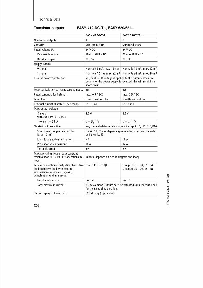
8/6/2019 Manual Easy 600
http://slidepdf.com/reader/full/manual-easy-600 211/229
Technical Data
208 1 1 / 9 9 A W B 2 5 2 8 - 1 3 0 4 G B
Transistor outputs EASY-412-DC-T..., EASY 620/621...
EASY 412-DC-T... EASY 620/621...
Number of outputs 4 8
Contacts Semiconductors Semiconductors
Rated voltage Ue 24 V DC 24 V DC
Permissible range 20.4 to 28.8 V DC 20.4 to 28.8 V DC
Residual ripple 5 % 5 %
Supply current
0 signal Normally 9 mA, max. 16 mA Normally 18 mA, max. 32 mA
1 signal Normally 12 mA, max. 22 mA Normally 24 mA, max. 44 mA
Reverse polarity protection Yes, caution! If voltage is applied to the outputs when thepolarity of the power supply is reversed, this will result in ashort circuit.
Potential isolation to mains supply, inputs Yes Yes
Rated current Ie for 1 signal max. 0.5 A DC max. 0.5 A DC
Lamp load 5 watts without RV 5 watts without RV
Residual current at state '0' per channel 0.1 mA 0.1 mA
Max. output voltage
0 signalwith ext. Last 10 M 2.5 V 2.5 V
1 when Ie = 0.5 A U = Ue–1 V U = Ue–1 V
Short-circuit protection Yes, thermal (detected via diagnostics input I16, I15; R15;R16)
Short-circuit tripping current forRa 10 m
0.7 A Ie 2 A (depending on number of active channelsand their load)
Max. total short-circuit current 8 A 16 A
Peak short-circuit current 16 A 32 A
Thermal cutout Yes Yes
Max. switching frequency at constantresistive load RL 100 k: operations perhour
40 000 (depends on circuit diagram and load)
Parallel connection of outputs with resistiveload; inductive load with externalsuppression circuit (see page 43)combination within a group
Group 1: Q1 to Q4 Group 1: Q1 – Q4, S1– S4Group 2: Q5 – Q8, S5– S8
Number of outputs max. 4 max. 4
Total maximum current 2.0 A, caution! Outputs must be actuated simultaneously andfor the same time duration.
Status display of the outputs LCD display (if provided)

8/6/2019 Manual Easy 600
http://slidepdf.com/reader/full/manual-easy-600 212/229
Transistor outputs
209 1 1 / 9 9 A W B 2 5 2 8 - 1 3 0 4 G B
Inductive load ((((wwwwiiiitttthhhhoooouuuutttt eeeexxxxtttteeeerrrrnnnnaaaallll ssssuuuupppppppprrrreeeessssssssoooorrrr cccciiiirrrrccccuuuuiiiitttt))))
General explanations:
T0.95 = time in msec. until 95 % of the stationary current is reached
Utilization category Q1 to Q4
T0.95 = 1 msR = 48 L = 16 mH
Utilization factor g = 0.25
Rel. duty factor 100%
Max. switching frequencyMax. duty factor
=> switching cycles per hour
f = 0.5 HzED = 50 %
1500
DC13T0.95 = 72 msR = 48 L = 1.15 H
Utilization factor g = 0.25
Rel. duty factor 100%
Max. switching frequencyMax. duty factor=> switching cycles per hour
f = 0.5 HzED = 50 %1500
Other inductive loads:
T0.95 = 15 msR = 48 L = 0.24 H
Utilization factor g = 0.25
Rel. duty factor 100%Max. switching frequencyMax. duty factor=> switching cycles per hour
f = 0.5 HzED = 50 %1500
Inductive load with external suppressor circuit for each load (seesection “Connecting transistor outputs” on page 41)
Utilization factor g = 1
Rel. duty factor 100%
Max. switching frequency
Max. duty factor=> switching cycles per hour
Depends on the
suppressorcircuit
T0,95 3T0,65 3L
R---=≈

8/6/2019 Manual Easy 600
http://slidepdf.com/reader/full/manual-easy-600 213/229
Technical Data
210 1 1 / 9 9 A W B 2 5 2 8 - 1 3 0 4 G B
Cycle time EASY 412-...
Table 4: List of times for processing function relays
Number Time duration
in s
Total
Basic pulse 1 210
Refresh 1 3500
Contacts and bridged contactfields
20
Coils 20
Circuit connections from thefirst one to the last one, withempty ones in between
50
Connecting lines (only f,v,d)
20
Timing relays (see Table 4) –
Counters (see Table 4) –
Analog value function relays(see Table 4)
–
Total
Number 1 2 3 4 5 6 7 8
Timing relays in s 20 40 80 120 160 200 240 280
Counters in s 20 50 90 130 170 210 260 310
Analog valueprocessors in s
80 100 120 140 160 180 220 260

8/6/2019 Manual Easy 600
http://slidepdf.com/reader/full/manual-easy-600 214/229
Cycle time
211 1 1 / 9 9 A W B 2 5 2 8 - 1 3 0 4 G B
EASY 600
Table 5: List of times for processing function relays
Number Time duration
in s
Total
Basic pulse 1 520
Refresh 5700
Contacts and bridged contactfields
40
Coils 20
Circuit connections from thefirst one to the last one, withempty ones in between
70
Connecting lines (only f,v,d)
40
Timing relays (see Table 5) –
Counters (see Table 5) –
Analog value function relays(see Table 5)
–
Total
Number 1 2 3 4 5 6 7 8
Timing relays in s 40 120 160 220 300 370 440 540
Counters in s 40 100 160 230 300 380 460 560
Analog valueprocessors in s
120 180 220 260 300 360 420 500

8/6/2019 Manual Easy 600
http://slidepdf.com/reader/full/manual-easy-600 215/229
212 1 1 / 9 9 A W B 2 5 2 8 - 1 3 0 4 G B

8/6/2019 Manual Easy 600
http://slidepdf.com/reader/full/manual-easy-600 216/229

8/6/2019 Manual Easy 600
http://slidepdf.com/reader/full/manual-easy-600 217/229
Glossary
214 1 1 / 9 9 A W B 2 5 2 8 - 1 3 0 4 G B
Function relays Function relays are provided for more complex
switching tasks. “easy” features the following types
of relay:Timing relays
Time switches
Counters
Analog comparators
Text marker relays
Impulse relay An impulse relay is a relay which changes its
switching state and stays changed (latched) when a
voltage is applied to the relay coil for a short time.
Input The inputs are used to connect up external contacts.
In the circuit diagram, inputs are evaluated via
contacts I1 to I12 and R1 to R12.
“easy
”24 V DC can also receive analog data via
inputs I7 and I8.
Interface The “easy” interface is used to exchange and save
circuit diagrams to a memory card or PC.
Each memory card contains one circuit diagram and
its associated “easy” settings.
The EASY-SOFT PC software allows you to control“easy” from your PC which is connected using the
“easy-PC CAB” cable.
Local expansion I/O expansion with the expansion unit (e.g.
EASY 620-DC-TE) installed directly on the basic unit.
The connector is always supplied with the expansion
unit.

8/6/2019 Manual Easy 600
http://slidepdf.com/reader/full/manual-easy-600 218/229
Glossary
215 1 1 / 9 9 A W B 2 5 2 8 - 1 3 0 4 G B
Memory card The memory card is used to store your “easy” circuit
diagram, together with its parameter and “easy”
settings. Your data on the memory card will beretained, even if the power supply fails or is switched
off.
The memory card is inserted into the interface slot on
the “easy” device.
Operating buttons “easy” has eight operating buttons. These are used
to select menu functions and create circuit diagrams.
The large round button in the middle is used to move
the cursor.
DEL, ALT, ESC and OK all perform additional
functions.
Operating mode “easy” has two operating modes: RUN and STOP.
RUN mode is used to process your circuit diagram
(with the controller running continuously). In STOPmode you can create your circuit diagrams.
Output You can connect various loads to the four “easy”
outputs, such as contactors, lamps or and motors. In
the “easy” circuit diagram the outputs are controlled
via the corresponding output relay coils Q1 to Q8 or
S1 to S8 (Q6).
P buttons The P buttons can be used to simulate four additional
inputs which are controlled directly by the four cursor
buttons, rather than via external contacts. The relay
contacts of P buttons are connected up in the circuit
diagram.

8/6/2019 Manual Easy 600
http://slidepdf.com/reader/full/manual-easy-600 219/229
Glossary
216 1 1 / 9 9 A W B 2 5 2 8 - 1 3 0 4 G B
Parameters Parameters enable the user to set the behaviour of a
function relay. Possible values include switching
times or counter setpoints. They are set in theparameter display.
Power supply “easy”-AC is powered by AC voltage at 115 to 240 V
AC, 50/60 Hz. The terminals are labeled “L” and “N”.
“easy”-DC is powered by DC voltage at 24 V DC. The
terminals are labeled “+24 V” and “0 V”.
The terminals for the power feed are the first threeterminals on the input side.
Remote expansion I/O expansion with the expansion unit (e.g.
EASY 620-DC-TE) installed up to 30 m away from
the basic unit. The EASY 200-EASY coupling unit is
fitted to the basic unit. The input and output data is
exchanged between expansion and basic unit via a
two-wire cable.
Retention Retentive data is kept even after the “easy” power
supply is switched off.
The following data is retentive:
“easy” circuit diagram
Parameters, setpoint values
Texts
System settings
Password entry
Actual values of marker relays, timing relays,
counters

8/6/2019 Manual Easy 600
http://slidepdf.com/reader/full/manual-easy-600 220/229
Index
217 1 1 / 9 9 A W B 2 5 2 8 - 1 3 0 4 G B
Index
Numerics
20 mA sensors ............................................................... 38
A
Accuracy
Analog comparators ................................................. 100
Actual values .................................................................. 78
Analog comparator
Hysteresis ................................................................. 100 Analog comparators
Parameters ............................................................... 102
AND circuit ................................................................... 109
B
Basic circuit
Changeover circuit ................................................... 110
Latching circuit ......................................................... 111
Negation ................................................................... 109
Parallel connection ................................................... 110Permanent contact ................................................... 109
Series connection ..................................................... 109
Break contact ........................................................... 61, 67
Buttons ........................................................................... 12
ALT ............................................................................. 53
DEL ............................................................................. 54
OK ........................................................................ 51, 60
C
Cable lengths ................................................................. 30
Cable protection ............................................................ 28
Changeover circuit ....................................................... 110
Changing menu level ..................................................... 51
Changing to summer time ........................................... 144
Changing to winter time ............................................... 144
Circuit connection
Deleting ...................................................................... 70
Inserting ................................................................ 53, 69
Circuit diagramChecking .................................................................... 72

8/6/2019 Manual Easy 600
http://slidepdf.com/reader/full/manual-easy-600 221/229
Index
218 1 1 / 9 9 A W B 2 5 2 8 - 1 3 0 4 G B
Circuit connection .......................................................62
Coil field ...................................................................... 62
Contacts ..................................................................... 62
Deleting ....................................................................... 56
Examples .................................................................. 108
Fast entry .................................................................... 57
Grid lines ...............................................................52, 62
Internal processing ...................................................175
Loading ............................................................. 127, 130
Operating buttons ....................................................... 60
Overview ..................................................................... 62
Storing ..............................................................127, 130
Testing ..................................................................55, 72Wiring .................................................................... 53, 67
Circuit diagram display ............................................. 51, 62
Coil field ..........................................................................62
Coil function ................................................................... 74
Impulse relays ............................................................. 75
Latching relays ............................................................ 76
Overview ..................................................................... 73
Comparing analog values ............................................... 98
Connecting
20 mA sensors ............................................................ 38 Analog inputs .............................................................. 35
Contactors, relays .......................................................39
Light intensity sensors ................................................ 37
Neon bulbs .................................................................31
Proximity switches ......................................................34
Push-button actuators, switches .......................... 30, 34
Setpoint potentiometers ............................................. 36
Temperature sensors .................................................. 38
Connecting relay outputs ............................................... 39
Connecting transistor outputs ........................................ 41Connections
Deleting ....................................................................... 68
Entry ............................................................................ 67
Position in the circuit diagram .................................... 62
Contact ...........................................................................67
Contact name ............................................................. 65
Contact number .......................................................... 65
Cursor buttons ............................................................ 70
Entry ............................................................................ 52
Inverting ...................................................................... 53

8/6/2019 Manual Easy 600
http://slidepdf.com/reader/full/manual-easy-600 222/229
Index
219 1 1 / 9 9 A W B 2 5 2 8 - 1 3 0 4 G B
Contact fields ................................................................. 62
Contactor ....................................................................... 74
Contacts
Deleting ...................................................................... 67
Entry ........................................................................... 65
Modifying .................................................................... 65
Overview ..................................................................... 61
Counter relays ................................................................ 90
Parameters ................................................................. 92
Cursor display .......................................................... 19, 60
Cycle ............................................................................ 175
DDebounce
Activating .................................................................. 145
Delay times
“easy”-DC ................................................................ 184
for “easy”-AC ........................................................... 185
Deleting retentive actual values ................................... 153
Deletion, retentive actual values .................................. 153
Determining counter frequency ..................................... 92
Determining the cycle time .......................................... 178
Dimensions, “easy” ...................................................... 197
E
Overview of “easy” ......................................................... 10
Entry
Contact ....................................................................... 52
Error handling ............................................................... 193
Examples
Impulse relay ............................................................ 157
S/R coil (break contact) ............................................ 156
S/R function .............................................................. 160Timing relay on-delayed ........................................... 163
Timing relay, off-delayed .......................................... 166
Timing relay, single-pulse ......................................... 168
F
Flicker effect ................................................................ 156
Function relays
Counter relays ............................................................ 90
Example ...................................................................... 78
Overview ..................................................................... 77

8/6/2019 Manual Easy 600
http://slidepdf.com/reader/full/manual-easy-600 223/229
Index
220 1 1 / 9 9 A W B 2 5 2 8 - 1 3 0 4 G B
Time switches ............................................................. 93
Timing relays ...............................................................84
H
Hysteresis
Analog comparator ...................................................100
I
Impulse .........................................................................157
Impulse relays ................................................................75
Increasing the input current ........................................... 32
Input contacts ................................................................65
InsertingCircuit connection .......................................................53
Interface ....................................................................... 125
Interference .................................................................... 30
Inverting ..........................................................................67
J
Jumps ...........................................................................105
L
Latching ..........................................................................74Latching circuit .............................................................111
Latching relays ...............................................................76
LED ................................................................................. 15
Light intensity sensors ....................................................37
Logic tables .......................................................... 108–111
M
Main menu
Overview ..................................................................... 16
Selecting ..................................................................... 13Make contact ............................................................ 61, 67
Marker relays .......................................................... 73, 177
Markers ..........................................................................73
Markers, retentive ......................................................... 156
Memory card
Deleting ..................................................................... 129
Inserting .................................................................... 127
Menu guidance ...............................................................12
Menu points
Toggling between .......................................................55

8/6/2019 Manual Easy 600
http://slidepdf.com/reader/full/manual-easy-600 224/229
Index
221 1 1 / 9 9 A W B 2 5 2 8 - 1 3 0 4 G B
Message
PROG INVALID ......................................... 129, 131, 195
System ..................................................................... 194
Mode
Changing .................................................................... 55
Mounting
Screws ........................................................................ 23
Top-hat rail ................................................................. 22
Mounting feet ................................................................. 23
N
NAND circuit ................................................................ 110
Neon bulbs ..................................................................... 31NOT circuit ................................................................... 109
O
Operating buttons .......................................................... 12
OR circuit ..................................................................... 110
Output relays .................................................................. 65
Overload ......................................................................... 43
Monitoring with EASY..-DC-T.. ................................ 187
PP buttons ........................................................................ 70
Activating and deactivating ...................................... 146
Parameter display
Analog comparators ................................................. 102
Counter relays ............................................................ 92
Time switches ............................................................. 97
Timing relays .............................................................. 85
Parameters
Changing .................................................................. 140
Changing the switching time .................................... 142Disable access ......................................................... 140
Display ...................................................................... 140
Power flow display ..................................................... 83
Password
Activating .................................................................. 135
Changing .................................................................. 137
Deleting .................................................................... 137
Remove protection ................................................... 138
Setting ...................................................................... 134
Unlocking “easy” ...................................................... 136

8/6/2019 Manual Easy 600
http://slidepdf.com/reader/full/manual-easy-600 225/229
Index
222 1 1 / 9 9 A W B 2 5 2 8 - 1 3 0 4 G B
PC connection ..............................................................130
Power failure ...................................................................48
Power flow display ....................................... 56, 71, 72, 83
R
Reed relay contacts ....................................................... 31
Relay coils
Deleting ....................................................................... 67
Entering ....................................................................... 54
Relay outputs .................................................................39
Relay types
Overview ..................................................................... 62
RelaysCoil function .......................................................... 65, 73
Entering ....................................................................... 65
Modifying .................................................................... 65
Name ..........................................................................65
Number ....................................................................... 65
Reset .............................................................................. 76
Restricting the inrush current ......................................... 32
Retention
Setting ....................................................................... 152
Retention requirementsPermitted “easy” models ..........................................151
Permitted markers and function relays ..................... 151
Retentive behaviour ......................................................154
Transfer of circuit diagrams ...................................... 154
RUN, Startup behaviour ................................................. 48
RUN/STOP toggle .......................................................... 55
S
Screw fixing .................................................................... 23
Set .................................................................................. 76Setpoint potentiometers ................................................. 36
Setpoints ................................................................78, 141
Setting the clock .......................................................... 143
Setting the menu language .................................... 47, 139
Setting the weekday .....................................................143
Short-circuit .................................................................... 43
Short-circuits
Monitoring with EASY..-DC-T.. .................................187
Signal .............................................................................. 75
Startup behaviour ......................................................... 148

8/6/2019 Manual Easy 600
http://slidepdf.com/reader/full/manual-easy-600 226/229
Index
223 1 1 / 9 9 A W B 2 5 2 8 - 1 3 0 4 G B
After deleting the circuit diagram ............................. 149
Default setting .......................................................... 148
During uploading and downloading to card or PC ... 149
Possible faults .......................................................... 149
Setting ...................................................................... 148
Status display ................................................................ 14
Status image ................................................................ 176
Suppressing contact bounce ....................................... 184
System menu ........................................................... 17, 18
Selecting ..................................................................... 13
T
Temperature sensors ..................................................... 38Text display .................................................................. 103
Time switches
Examples .................................................................... 94
Parameters ................................................................. 97
Timing relays
Flashing ...................................................................... 89
Off-delayed ................................................................. 87
On-delayed ................................................................. 86
Parameters ................................................................. 85
Retentive .................................................................. 161Single pulse ................................................................ 88
Wiring ......................................................................... 84
Torque ............................................................................ 25
Transfer cable .............................................................. 130
Transistor outputs .......................................................... 41
Two-wire proximity switches ......................................... 32
Type overview ................................................................ 11
W
WiringBackwards ................................................................ 177
Deleting ...................................................................... 54
Entry ........................................................................... 53
Relays ......................................................................... 74
Rules ........................................................................... 74
X
XOR circuit ................................................................... 110

8/6/2019 Manual Easy 600
http://slidepdf.com/reader/full/manual-easy-600 227/229
Index
224 1 1 / 9 9 A W B 2 5 2 8 - 1 3 0 4 G B

8/6/2019 Manual Easy 600
http://slidepdf.com/reader/full/manual-easy-600 228/229
"easy" Control Relay Circuit DiagramCustomer: Program:
Date: Page:
Comment:
( 0 3 / 9 8 ) F O 9
8
D M .
P r i n t e d i n t h e F e d e r a l R e p u b
l i c o f G e r m a n y ( 0 7 / 9 8 )

8/6/2019 Manual Easy 600
http://slidepdf.com/reader/full/manual-easy-600 229/229
"easy" Control Relay Circuit DiagramCustomer: Program:
Date: Page:
Timing relays