Manual Del 7890A Calibrar Columna
406
Agilent Technologies Agilent 7890A Gas Chromatograph Advanced User Guide
-
Upload
alexis-agonzalez-san-martin -
Category
Documents
-
view
56 -
download
3
Transcript of Manual Del 7890A Calibrar Columna
Agilent Technologies
Agilent 7890A Gas Chromatograph
Advanced User Guide
Notices© Agilent Technologies, Inc. 2007-2012
No part of this manual may be reproduced in any form or by any means (including electronic storage and retrieval or transla-tion into a foreign language) without prior agreement and written consent from Agilent Technologies, Inc. as governed by United States and international copyright laws.
Manual Part Number
G3430-90015
Edition
Eleventh edition, July 2012 Tenth edition, March 2012 Ninth edition, June 2011 Eighth edition, February 2011 Seventh edition, November 2010 Sixth edition, June 2010 Fifth edition, September 2009 Fourth edition, April 2009 Third edition, September 2008 Second edition, January 2008 First edition, April 2007
Printed in USA
Agilent Technologies, Inc. 2850 Centerville Road Wilmington, DE 19808-1610 USA
安捷伦科技(上海)有限公司 上海市浦东新区外高桥保税区 英伦路 412 号 联系电话:(800)820 3278
Safety Notices
CAUTION
A CAUTION notice denotes a hazard. It calls attention to an operating procedure, practice, or the like that, if not correctly performed or adhered to, could result in damage to the product or loss of important data. Do not proceed beyond a CAUTION notice until the indicated conditions are fully understood and met.
WARNING
A WARNING notice denotes a hazard. It calls attention to an operating procedure, practice, or the like that, if not correctly performed or adhered to, could result in personal injury or death. Do not proceed beyond a WARNING notice until the indicated conditions are fully understood and met.
Firmware Version
This manual is written for 7890A GCs using firmware version A.01.14.
Advanced User Guide 3
Contents
1 Programming
Run Time Programming 16
Using run time events 16Programming run time events 17The run table 17Adding events to the run table 17Editing events in the run table 18Deleting run time events 18
Clock Time Programming 19
Using clock time events 19Programming clock time events 19Adding events to the clock table 20Editing clock time events 20Deleting clock time events 20
User-Key Programming 21
To program a User Key 21To play back (execute) the stored keystrokes 21To erase the stored keystrokes 21
Post Run Programming 22
To enable a post run program 22To disable a post run program 22
2 Configuration
About Configuration 24
Assigning GC resources to a device 24Setting configuration properties 25
General Topics 26
Unlock the GC Configuration 26Ignore Ready = 26Information displays 27Unconfigured: 27
Oven 28
To configure the oven 28To configure the oven for cryogenic cooling 29
Front Inlet/Back Inlet 30
To configure the Gas type 30To configure the PTV or COC coolant 30To configure the MMI coolant 32
4 Advanced User Guide
Column # 34
To configure a single column 34To view a summary of column connections 37To configure multiple columns 37
Composite Columns 42
To configure composite columns 43
LTM Columns 44
LTM Series II column modules 44
Cryo Trap 45
Configure the cryo trap to the GC 45Configure a heater to the cryo trap 45Configure the coolant 45Configure the user-configurable heater 46Reboot the GC 46
Front Detector/Back Detector/Aux Detector/Aux Detector 2 47
To configure the makeup/reference gas 47Lit offset 47To configure the FPD heaters 47To ignore the FID or FPD ignitor 48
Analog out 1/Analog out 2 49
Fast peaks 49
Valve Box 50
To assign a GC power source to a valve box heater 50
Thermal Aux 51
To assign a GC power source to an Aux thermal zone 51To configure a MSD transfer line heater 52To configure a nickel catalyst heater 52To configure an AED transfer line heater 53To configure an ion trap transfer line heater 53
PCM A/PCM B/PCM C 54
To assign a GC communication source to a PCM 54To configure a PCM 54
Pressure aux 1,2,3/Pressure aux 4,5,6/Pressure aux 7,8,9 56
To assign a GC communication source to an Aux EPC 56To configure an auxiliary pressure channel 56
Status 57
The Ready/Not Ready status table 57The setpoint status table 57To configure the setpoint status table 57
Advanced User Guide 5
Time 58
To set time and date 58To use the stopwatch 58
Valve # 59
To configure a valve 59
Front injector/Back injector 60
Solvent Wash Mode (7683 ALS) 60To configure an injector (7683 ALS) 61To move a 7683 injector between front and back positions 61
Sample tray (7683 ALS) 62
Instrument 63
3 Options
About Options 66
Calibration 67
Maintaining EPC calibration—inlets, detectors, PCM, and AUX 67To zero a specific flow or pressure sensor 68To zero all pressure sensors in all modules 69Column calibration 69
Communication 73
Configuring the IP address for the GC 73
Keyboard and Display 74
4 Chromatographic Checkout
About Chromatographic Checkout 78
To Prepare for Chromatographic Checkout 79
To Check FID Performance 81
To Check TCD Performance 86
To Check NPD Performance 91
To Check uECD Performance 96
To Check FPD Performance (Sample 5188-5953) 101
To Verify FPD Performance (Sample 5188-5245, Japan) 108
5 Methods and Sequences
Creating Methods 116
To program a method 117To program the ALS 117To program the ALS sampler tray 117
6 Advanced User Guide
To program the 7683B ALS bar code reader 118To save a method 119To load a stored method 119Method mismatch 120
Creating Sequences 121
About the priority sequence 121To program a sequence 122To program a priority sequence 122To program an ALS subsequence 123To program a valve subsequence 123To program post sequence events 123To save a sequence 124To load a stored sequence 124To determine sequence status 124To start a sequence 124To pause and resume a sequence 125To stop a sequence 125To abort a sequence 125
6 Checking for Leaks
Preparing the GC for Maintenance 128
Column and oven preparation 128Inlet preparation 128Detector preparation 128
Leak Check Tips 129
To Check for External Leaks 130
To Check for GC Leaks 131
Leaks in Capillary Flow Technology (CFT) Fittings 132
To Perform a SS Inlet Pressure Decay Test 133
To Correct Leaks in the Split Splitless Inlet 137
To Perform a Multimode Inlet Pressure Decay Test 138
To Correct Leaks in the Multimode Inlet 142
To Perform a PP Inlet Pressure Decay Test 143
To Correct Leaks in the Packed Column Inlet 147
To Perform a COC Pressure Decay Test 148
To Correct Leaks in the Cool On-Column Inlet 151
To Perform a PTV Pressure Decay Test 152
To Correct Leaks in the PTV Inlet 156
Advanced User Guide 7
To Perform a VI Pressure Decay Test 157
To Prepare the VI for a Closed System Leak Check 161
To Correct Leaks in the Volatiles Interface 162
7 Flow and Pressure Modules
About Flow and Pressure Control 164
Maximum operating pressure 164PIDs 165
Inlet Modules 166
Detector Modules 167
Pressure Control Modules 168
Auxiliary Pressure Controllers 171
Restrictors 172
Examples 174
1. Using an Aux EPC channel to supply purge gas to a splitter 1742. Using the PCM channels 174
8 Inlets
Using Hydrogen 179
Inlet Overview 180
Carrier Gas Flow Rates 181
About Gas Saver 182
To use gas saver 182
Pre Run and Prep Run 184
The [Prep Run] key 184Auto Prep Run 185
About Heaters 186
About the Split/Splitless Inlet 188
Septum tightening (S/SL) 188Standard and high-pressure versions of the S/SL inlet 188Split/Splitless inlet split mode overview 189Split/Splitless inlet splitless mode overview 190The S/SL inlet pulsed split and splitless modes 191Split/Splitless inlet split mode minimum operating pressures 192Selecting the correct S/SL inlet liner 193Vapor Volume Calculator 195Setting parameters for the S/SL split mode 195Selecting parameters for the S/SL splitless mode 196
8 Advanced User Guide
Setting parameters for the S/SL splitless mode 197Setting parameters for the S/SL pulsed modes 198
About the Multimode Inlet 199
Septum tightening (MMI) 199Heating the MMI 200Cooling the MMI 200MMI split mode minimum operating pressures 201Selecting the correct MMI liner 202Vapor Volume Calculator 204MMI split and pulsed split modes 204MMI splitless and pulsed splitless modes 208MMI solvent vent mode 214MMI Direct Mode 222To develop a MMI method that uses large volume injection 223Multiple injections with the MMI 226
About the Packed Column Inlet 232
Setting parameters 234
About the Cool On-Column Inlet 236
Setup modes of the COC inlet 237Retention gaps 237COC inlet temperature control 237Setting COC inlet flows/pressures 238Setting COC inlet parameters 239
About the PTV Inlet 240
PTV sampling heads 240Heating the PTV inlet 241Cooling the PTV inlet 242PTV inlet split and pulsed split modes 242PTV inlet splitless and pulsed splitless modes 246PTV inlet solvent vent mode 253To develop a PTV method that uses large volume injection 261Multiple injections with the PTV inlet 264
About the Volatiles Interface 270
VI operating modes 271About the VI split mode 272About the VI splitless mode 276About the VI direct mode 281Preparing the Interface for Direct Sample Introduction 284VI direct mode setpoint dependencies 286VI direct mode initial values 286Setting parameters for the VI direct mode 287
Advanced User Guide 9
9 Columns and Oven
About the Oven 290
Oven safety 290
Configuring the Oven 291
Cryogenic Operation 292
Cryogenic setpoints 292
About Oven Temperature Programming 294
Programming setpoints 294Oven ramp rates 295Setting the oven parameters for constant temperature 296Setting the oven parameters for ramped temperature 296
About the Oven Insert 298
About Columns 299
Selecting the correct packed glass column type 299About the column modes 299Select a column mode 300Setting the column parameters for constant flow or constant
pressure 301Enter a flow or pressure program (optional) 301Programming column pressure or flow 302
Backflushing a Column 303
Backflushing when connected to an MSD 304Backflushing using a capillary flow technology device 304
Nickel Catalyst Tube 309
About the nickel catalyst tube 309Nickel catalyst gas flows 309Setting temperatures for the nickel catalyst tube 310
10 Detectors
About Makeup Gas 312
About the FID 313
How FID units are displayed in Agilent data systems and on the GC 314To light the FID flame 315To extinguish the FID flame 315FID automatic reignition (Lit offset) 315Recommended starting conditions for new FID methods 316Setting parameters for FID 317
10 Advanced User Guide
About the TCD 318
TCD pneumatics 320TCD carrier, reference, and makeup gas 320TCD gas pressures 321Selecting reference and makeup flows for the TCD 322Chemically active compounds reduce TCD filament life 322Changing the TCD polarity during a run 323Detecting hydrogen with the TCD using helium carrier gas 323Setting parameters for the TCD 324
About the uECD 326
uECD safety and regulatory information 326uECD warnings 327Safety precautions when handling uECDs 328uECD gas flows 329uECD linearity 329uECD detector gas 329uECD temperature 329uECD analog output 330Recommended starting conditions for new uECD methods 330uECD makeup gas notes 330uECD temperature programming 331Setting parameters for the uECD 331
About the NPD 332
New NPD features and changes 332NPD software requirements 332NPD flows and general information 332NPD flow, temperature, and bead recommendations 333NPD required gas purity 335Setting parameters for the NPD 336Selecting an NPD bead type 337Changing from a ceramic bead to a Blos bead 338Selecting an NPD jet 338To configure the NPD 339Automatically adjusting NPD bead voltage 340Setting NPD adjust offset on the clock table 341Aborting NPD adjust offset 341Extending the NPD bead life 341Setting the initial bead voltage for new beads 342Setting NPD bead voltage manually (optional) 343
About the FPD 344
FPD linearity 345FPD Lit Offset 345
Advanced User Guide 11
Starting Up and Shutting Down the FPD 345FPD photomultiplier protection 345FPD optical filters 345Inlet liners for use with the FPD 346FPD temperature considerations 346FPD gas purity 346FPD gas flows 346Lighting the FPD flame 347Setting parameters for the FPD 348
11 Valves
About Valves 352
The Valve Box 353
Heating the valves 353Valve temperature programming 353Configuring an Aux thermal zone 354
Valve Control 355
The valve drivers 355The internal valve drivers 355The external valve drivers 356
Valve Types 357
Configuring a Valve 358
Controlling a Valve 359
From the keyboard 359From the run or clock time tables 359Simple valve: column selection 359Gas sampling valve 360Multiposition stream selection valve with sampling valve 361
12 7683B Sampler
About the 7683B Sampler 364
Hardware 364Software 364
Setting Parameters for the ALS 365
Solvent Saver 366Sample tray setpoints 367Storing setpoints 367
12 Advanced User Guide
13 Cables
About Cables and Back Panel Connectors 370
Back panel connectors 370Sampler connectors 370The AUX connector 370Signal connectors 371REMOTE connector 371EVENT connector 371BCD input connector 371RS-232 connector 371LAN connector 371
Using the Remote Start/Stop cable 372
Connecting Agilent products 372Connecting non-Agilent products 372
Connecting Cables 375
Cable Diagrams 377
Analog cable, general use 377Remote start/stop cable 377BCD cable 378External event cable 379
14 GC Output Signals
About Signals 382
Signal Types 383
Value 383
Analog Signals 385
Analog zero 385Analog range 385Analog data rates 386Selecting fast peaks (analog output) 387
Digital Signals 388
Digital zero 388Signal Freeze and Resume 388Data rates with Agilent data systems 389Zero Init Data Files 391
Column Compensation 392
Creating a column compensation profile 393Making a run using analog output column compensation 393Making a run using digital output column compensation 393Plotting a stored column compensation profile 394
Test Plot 395
Advanced User Guide 13
15 Miscellaneous Topics
Auxiliary Devices 398
About Auxiliary Pressure Control 398About Aux Thermal Zone Control 399About Cryo Trap Control 399About Auxiliary Device Contacts 400About the 24V Auxiliary Device Power Supply 400About Auxiliary Columns 400About Auxiliary Detectors 401
To Use the Stopwatch 402
Service Mode 403
Service Reminders 403Other functions 405

14 Advanced User Guide

15
Agilent 7890A Gas ChromatographAdvanced User Guide
Agilent Technologies
1Programming
Run Time Programming 16
Using run time events 16
Programming run time events 17
The run table 17
Adding events to the run table 17
Editing events in the run table 18
Deleting run time events 18
Clock Time Programming 19
Using clock time events 19
Programming clock time events 19
Adding events to the clock table 20
Editing clock time events 20
Deleting clock time events 20
Post Run Programming 22
User-Key Programming 21
To play back (execute) the stored keystrokes 21
To erase the stored keystrokes 21
To program a User Key 21
16 Advanced User Guide
1 Programming
Run Time Programming
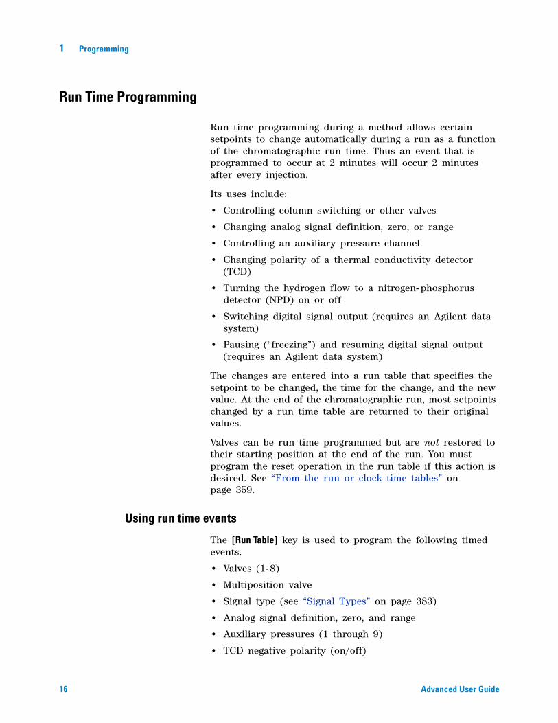
Run time programming during a method allows certain setpoints to change automatically during a run as a function of the chromatographic run time. Thus an event that is programmed to occur at 2 minutes will occur 2 minutes after every injection.
Its uses include:
• Controlling column switching or other valves
• Changing analog signal definition, zero, or range
• Controlling an auxiliary pressure channel
• Changing polarity of a thermal conductivity detector (TCD)
• Turning the hydrogen flow to a nitrogen- phosphorus detector (NPD) on or off
• Switching digital signal output (requires an Agilent data system)
• Pausing (“freezing”) and resuming digital signal output (requires an Agilent data system)
The changes are entered into a run table that specifies the setpoint to be changed, the time for the change, and the new value. At the end of the chromatographic run, most setpoints changed by a run time table are returned to their original values.
Valves can be run time programmed but are not restored to their starting position at the end of the run. You must program the reset operation in the run table if this action is desired. See “From the run or clock time tables” on page 359.
Using run time events
The [Run Table] key is used to program the following timed events.
• Valves (1- 8)
• Multiposition valve
• Signal type (see “Signal Types” on page 383)
• Analog signal definition, zero, and range
• Auxiliary pressures (1 through 9)
• TCD negative polarity (on/off)

Programming 1
Advanced User Guide 17
• Detector gas flow (on/off), including NPD H2 fuel gas
• Inlet septum purge flow
Programming run time events
1 Press [Run Table].
2 Press [Mode/Type] to see the available run time events.
3 Scroll to the event to be programmed. Press [Enter].
4 Enter values for the Time: and the other parameter. Press [Enter] after each entry.
5 Press [Mode/Type] to add another event. Press [Status] to terminate entries.
The run table
The programmed events are arranged in order of execution time in the Run Table. This is a brief example:
RUN TABLE (1 of 3) Event 1 rotates a valve. Time: 0.10 Valve #2 On RUN TABLE (2 of 3) Event 2 adjusts the signal Time: 3 range. Analog signal 2 range 2 RUN TABLE (3 of 3) Event 3 resets Valve #2 to its Time: 4.20 original position in preparation Valve #2 Off for another run. Valves do not
reset automatically.
Adding events to the run table
1 To add new events to the run table, press [Mode/Type] while on the Time: line of any entry.
2 Select the event type.
3 Set appropriate Time: and other parameters. Some require numbers; others require [On/Yes] or [Off/No].
4 Repeat until all entries are added. Events are automatically placed in order by execution time.
18 Advanced User Guide
1 Programming
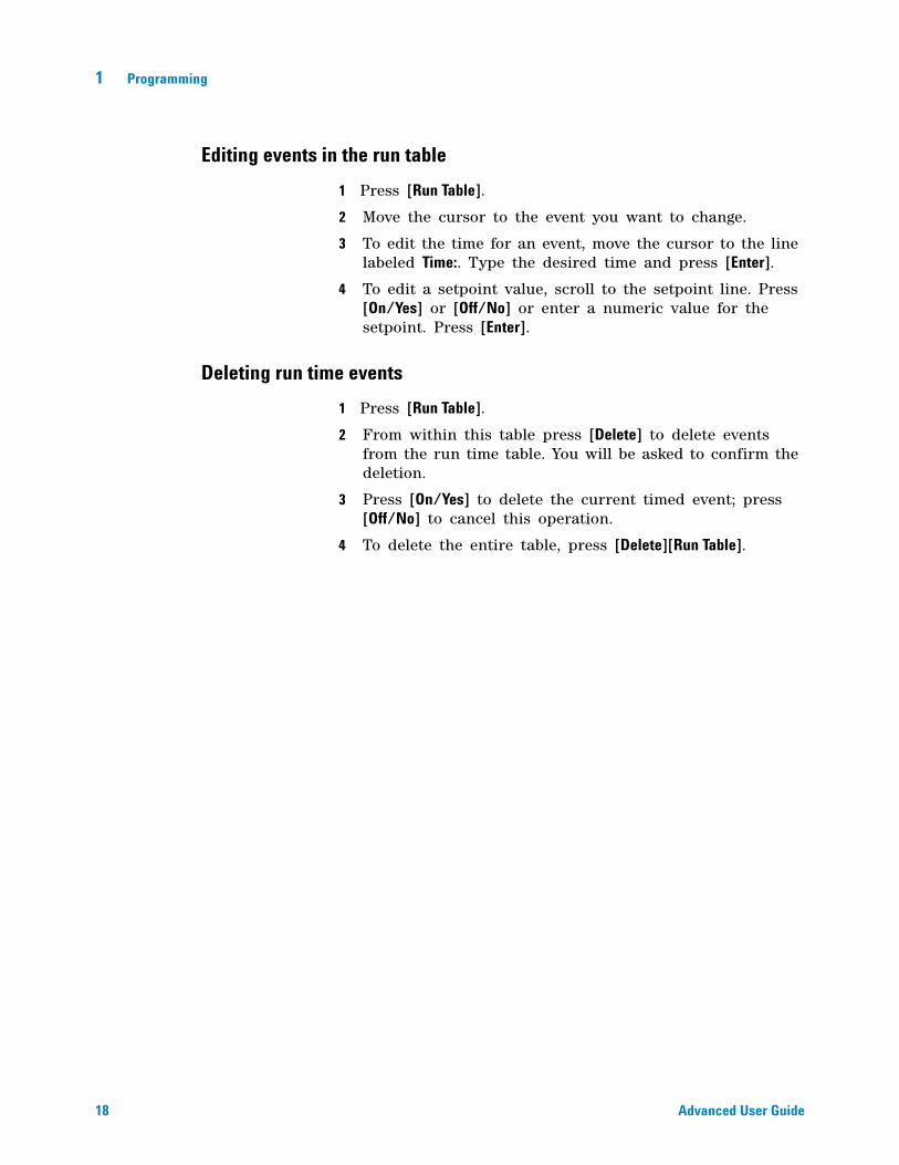
Editing events in the run table
1 Press [Run Table].
2 Move the cursor to the event you want to change.
3 To edit the time for an event, move the cursor to the line labeled Time:. Type the desired time and press [Enter].
4 To edit a setpoint value, scroll to the setpoint line. Press [On/Yes] or [Off/No] or enter a numeric value for the setpoint. Press [Enter].
Deleting run time events
1 Press [Run Table].
2 From within this table press [Delete] to delete events from the run time table. You will be asked to confirm the deletion.
3 Press [On/Yes] to delete the current timed event; press [Off/No] to cancel this operation.
4 To delete the entire table, press [Delete][Run Table].
Programming 1
Advanced User Guide 19
Clock Time Programming
Clock time programming allows certain setpoints to change automatically at a specified time during a 24- hour day. Thus, an event programmed to occur at 14:35 hours will occur at 2:35 in the afternoon. A running analysis or sequence has precedence over any clock table events occurring during this time. Such events are not executed.
Possible clock time events include:
• Valve control
• Method and sequence loading
• Starting sequences
• Initiating blank and prep runs
• Column compensation changes
• Adjustments of the detector offset
Using clock time events
The Clock Table function allows you to program events to occur during a day based on the 24- hour clock. Clock table events that would occur during a run or sequence are ignored.
For example, the clock table could be used to make a blank run before you even get to work in the morning.
Programming clock time events
1 Press [Clock Table].
2 Press [Mode/Type] to see the available clock time events.
3 Scroll to the parameter to be programmed.
4 Edit Time: and the setpoints for this event.
5 Press [Mode/Type] to add another event. Press [Status] to terminate entries.
When the clock event is executed, a confirming message appears.
20 Advanced User Guide
1 Programming
Adding events to the clock table
1 Press [Clock Table].
2 Press [Mode/Type]. When entries are added, they are automatically ordered chronologically.
3 Select the event type.
4 Set appropriate parameters.
5 Repeat this process until all entries are added.
Editing clock time events
1 Press [Clock Table] to view all events programmed.
2 Scroll to the event you want to change.
3 To edit the time for an event, move the cursor to the line labelled Time: and type the desired time.
4 To edit a setpoint value, scroll to the setpoint item. Press [On/Yes] or [Off/No], or enter a numerical value for the setpoint.
Deleting clock time events
1 Press [Clock Table].
2 Use [Delete] to remove events from the clock time table. You will be asked to confirm the deletion.
3 Press [On/Yes] to delete the current timed event; press [Off/No] to cancel this operation.
To delete the entire table, press [Delete][Clock Table].
Programming 1
Advanced User Guide 21
User-Key Programming
The two User Keys create macros (sets of frequently used keystrokes) and assign them to single keys. A macro is executed when the User Key is pressed.
The stored keystrokes may be any keys except [Start], [Prog], [User Key 1], or [User Key 2].
This discussion assumes that you wish to program [User Key 1]. The process is the same for [User Key 2].
To program a User Key
1 Press [Prog]. Press [User Key 1].
2 Press up to 31 keys, then press [User Key 1]. The keystrokes are stored.
To play back (execute) the stored keystrokes
Press [User Key 1].
To erase the stored keystrokes
Press [Prog][User Key 1][User Key 1]. This creates an “empty” macro.
22 Advanced User Guide
1 Programming
Post Run Programming
This function can be used with both isothermal and programmed methods. Post run is a period that begins at the end of the normal run. The parameters include:
• Time—How long is the post run period?
• Oven Temperature—What is the oven temperature during the post run period?
• Column n pres—For a column controlled in a pressure mode, enter the pressure for this column during the post run period.
• Column n flow—For a column controlled in a flow mode, enter the flow rate for this column during the post run period.
• Enable Front inlet temp—For the Multimode inlet, set the post run inlet temperature. You can also press [On/Yes] and [Off/No] to turn this parameter on or off.
• Enable Front inlet total flow—For the Multimode inlet, set the post run inlet total flow rate. You can also press [On/Yes] and [Off/No] to turn this parameter on or off.
Post run may be used to clean out a column in preparation for the next run, backflush a column to eliminate high- boilers, and other functions.
When the Post run Time elapses, the GC returns to the initial state defined in the current method. If it uses cryogenic cooling and you do not start another run quickly, you could waste considerable coolant while waiting for the next run. A solution is to use a sequence that loads a less wasteful method.
To enable a post run program
1 Press [Post Run].
2 Type a non- zero time for the post run duration and press [Enter]. The post run parameters available for the current GC configuration appear.
3 Scroll to each desired parameter, type the value for the post run period, and press [Enter].
To disable a post run program
1 Press [Post Run].
2 Type a 0 as the post run time and press [Enter].
23
Agilent 7890A Gas ChromatographAdvanced User Guide
Agilent Technologies
2ConfigurationAbout Configuration 24
Assigning GC resources to a device 24
Setting configuration properties 25
General Topics 26
Unlock the GC Configuration 26
Ignore Ready = 26
Information displays 27
Unconfigured: 27
Oven 28
Front Inlet/Back Inlet 30
To configure the PTV or COC coolant 30
To configure the MMI coolant 32
Column # 34
To configure a single column 34
To configure multiple columns 37
Composite Columns 42
LTM Columns 44
Cryo Trap 45
Front Detector/Back Detector/Aux Detector/Aux Detector 2 47
Analog out 1/Analog out 2 49
Fast peaks 49
Valve Box 50
Thermal Aux 51
To assign a GC power source to an Aux thermal zone 51
To configure a MSD transfer line heater 52
To configure a nickel catalyst heater 52
To configure an ion trap transfer line heater 53
PCM A/PCM B/PCM C 54
Pressure aux 1,2,3/Pressure aux 4,5,6/Pressure aux 7,8,9 56
Status 57
Time 58
Valve # 59
Front injector/Back injector 60
Sample tray (7683 ALS) 62
Instrument 63
24 Advanced User Guide
2 Configuration
About Configuration
Configuration is a two- part process for most GC accessory devices that require power and/or communication resources from the GC. In the first part of the configuration process, a power and/or communication resource is assigned to the device. The second part of the configuration process allows setting of any configuration properties associated with the device.
Assigning GC resources to a device
A hardware device requiring but not assigned GC resources is given a mode of Unconfigured by the GC. Once you assign GC resources to a device, the GC gives the device a mode of Configured, allowing you to access other property settings (if any) for the device.
To assign GC resources to a device with an Unconfigured mode:
1 Unlock the GC configuration. Press [Options], select Keyboard & Display and press [Enter]. Scroll down to Hard Configuration Lock and press [Off/No].
2 Press [Config] on the GC keypad and select a device from the list, then press [Enter].
The [Config] key opens a menu similar to this:
Oven Front inlet Back Inlet Column # Front detector Back detector Aux detector Aux detector 2 Analog out 1 Analog out 2 Valve Box Thermal Aux 1 Thermal Aux 2 Thermal Aux 3 PCM A PCM B PCM C Aux EPC 1,2,3 Aux EPC 4,5,6
Configuration 2
Advanced User Guide 25
Aux EPC 7,8,9 Status Time Valve # 2 Dimensional GC Valve Front injector Back injector Sample tray Instrument
In many cases you can move directly to the item of interest by pressing [Config][device].
3 When the Configure Device Display opens, the cursor should be on the Unconfigured field. Press [Mode/Type] and follow the GC prompts to assign resources to the device.
4 After assigning resources, the GC prompts for you to power cycle the GC. Turn the GC power switch off and then on.
When the GC starts, select the device just assigned the GC resources for further configuration if needed. When accessed, its mode should indicate Configured and the other configuration properties are displayed.
Setting configuration properties
A device’s configuration properties are constant for an instrument hardware setup unlike method settings which can change from sample run to sample run. An example of a configuration setting is the gas type flowing through a pneumatic device or the operation temperate limit of a device.
To change the setting configuration properties for a Configured device:
1 Press [Config] on the GC keypad and select a device from the list, then press [Enter].
In many cases you can move directly to the item of interest by pressing [Config][device].
2 Scroll to the device setting and change the property. This can involve making a selection from a list using [Mode/Type], using [On/Yes] or [Off/No], or entering a numeric value. Press [Info] for help on changing numeric settings, or see the section of this document describing the specific configuration of the device.

26 Advanced User Guide
2 Configuration
General Topics
Unlock the GC Configuration
Accessory devices including inlets, detectors, pressure controllers (AUX EPC and PCM), and temperature control loops (Thermal AUX) have electrical connections to a power source and/or the communication bus in the GC. These devices must be assigned GC resources before they can be used. Before assigning resources to a device, you must first unlock the GC configuration. If you try to configure an Unconfigured device without unlocking the GC configuration, the GC displays the message CONFIGURATION IS LOCKED Go to Keyboard options to unlock.
It is also necessary to unlock the GC configuration if you are removing the GC resources from a Configured device. This action returns the device state to Unconfigured.
To unlock the GC configuration, press [Options], select Keyboard & Display and press [Enter]. Scroll down to Hard Configuration Lock and press [Off/No].
The GC configuration remains unlocked until the GC is power cycled off and on.
Ignore Ready =
The states of the various hardware elements are among the factors that determine whether the GC is Ready for analysis.
Under some circumstances, you may not wish to have a specific element readiness considered in the GC readiness determination. This parameter lets you make that choice. The following elements allow readiness to be ignored: inlets, detectors, the oven, PCM, and auxiliary EPC modules.
For example, suppose an inlet heater is defective but you don’t plan to use that inlet today. By setting Ignore Ready = TRUE for that inlet, you can use the rest of the GC. After the heater is repaired, set Ignore Ready = FALSE or the run could start before that inlet’s conditions are ready.
To ignore an element's readiness, press [Config], then select the element. Scroll to Ignore Ready and press [On/Yes] to set it to True.
To consider an element's readiness, press [Config], then select the element. Scroll to Ignore Ready and press [Off/No] to set it to False.
Configuration 2
Advanced User Guide 27
Information displays
Below are some examples of configuration displays:
[ EPC1 ] = (INLET) (SS) EPC #1 is used for an inlet of type split/splitless. It is not available for other uses.
[ EPC3 ] = (DET-EPC) (FID) EPC #3 is controlling detector gases to an FID.
[ EPC6 ] = (AUX_EPC) (PCM) EPC #6 is controlling a two- channel pressure control module.
FINLET (OK) 68 watts 21.7 This heater is connected to the front inlet. Status = OK, meaning that it is ready for use. At the time that the GC was turned on, the heater was drawing 68 watts and the inlet temperature was 21.7 °C.
[ F-DET ] = (SIGNAL) (FID) The signal board for the front detector is type FID.
AUX 2 1 watts (No sensor) The AUX 2 heater is either not installed or not OK.
Unconfigured:
Accessory devices requiring GC power or communication must be assigned these GC resources before they can be used. To make this hardware element usable, first “Unlock the GC Configuration” on page 26 then go to the Unconfigured parameter and press [Mode/Type] to install it. If the hardware element you are configuring requires selection of additional parameters, the GC asks for that selection. If no parameters are required, press [Enter] at the GC prompt to install that element. You are required to power the GC off and then power the GC on to complete this configuration.
After restarting the GC, a message reminding you of this change and its effect on the default method is displayed. If needed, change your methods to accommodate the new hardware.
28 Advanced User Guide
2 Configuration
Oven
See “Unconfigured:” on page 27 and “Ignore Ready =” on page 26.
Maximum temperature Sets an upper limit to the oven temperature. Used to prevent accidental damage to columns. The range is 70 to 450 °C.
Equilibration time The time after the oven approaches its setpoint before the oven is declared Ready. The range is 0 to 999.99 minutes. Used to ensure that the oven contents have stabilized before starting another run.
Cryo These setpoints control liquid carbon dioxide (CO2 or liquid nitrogen (N2) cooling of the oven.
The cryogenic valve lets you operate the oven below ambient temperature. Minimum attainable oven temperature depends on the type of valve installed.
The GC senses the presence and type of cryogenic valve and disallows setpoints if no valve is installed. When cryogenic cooling is not needed or cryogenic coolant is not available, the cryogenic operation should be turned off. If this is not done, proper oven temperature control may not be possible, particularly at temperatures near ambient.
External oven mode Isothermal internal oven and programmed external oven used to calculate column flow.
Slow oven cool down mode On reduces the oven fan speed during the cool down cycle.
To configure the oven
1 Press [Config][Oven].
2 Scroll to Maximum temperature. Enter a value and press [Enter].
3 Scroll to Equilibration time. Enter a value and press [Enter].
4 Scroll to Cryo. Press [On/Yes] or [Off/No]. If On, enter the setpoints described in “To configure the oven for cryogenic cooling” on page 29.
5 Scroll to External oven mode. Press [On/Yes] or [Off/No].
Configuration 2
Advanced User Guide 29
6 Scroll to Slow oven cool down mode. Press [On/Yes] to run the oven fan at reduced speed during cool down, or [Off/No] to run it at normal speed.
To configure the oven for cryogenic cooling
All cryogenic setpoints are in the [Config][Oven] parameter list.
Cryo [ON] enables cryogenic cooling, [OFF] disables it.
Quick cryo cool This feature is separate from Cryo. Quick cryo cool makes the oven cool faster after a run than it would without assistance. This feature is useful when maximum sample throughput is necessary, however it does use more coolant. Quick cryo cool turns off soon after the oven reaches its setpoint and Cryo takes over, if needed.
Ambient temp The temperature in the laboratory. This setpoint determines the temperature at which cryogenic cooling is enabled:
• Ambient temp + 25°C, for regular cryo operation
• Ambient temp + 45°C, for Quick Cryo Cool.
Cryo timeout Cryo timeout occurs, and the oven shuts off, when a run does not start within a specified time (10 to 120 minutes) after the oven equilibrates. Turning cryo timeout off disables this feature. We recommend that it be turned on because cryo timeout conserves coolant at the end of a sequence or if automation fails.
Cryo fault Shuts the oven down if it does not reach setpoint temperature after 16 minutes of continuous cryo operation. Note that this is the time to reach the setpoint, not the time to stabilize and become ready at the setpoint. For example, with a cool on- column inlet and cryo control in the oven track mode, it may take the oven 20 to 30 minutes to achieve readiness.
If the temperature goes below the minimum allowed temperature (–90°C for liquid nitrogen, –70°C for liquid CO2), the oven will shut down.
The COC and PTV inlets must use the same cryo type as configured for the oven.
30 Advanced User Guide
2 Configuration
Front Inlet/Back Inlet
See “Unconfigured:” on page 27 and “Ignore Ready =” on page 26.
To configure the Gas type
The GC needs to know what carrier gas is being used.
1 Press [Config][Front Inlet] or [Config][Back Inlet].
2 Scroll to Gas type and press [Mode/Type].
3 Scroll to the gas you will use. Press [Enter].
This completes carrier gas configuration.
To configure the PTV or COC coolant
Press [Config][Front Inlet] or [Config][Back Inlet]. If the inlet has not been configured previously, a list of available coolants is displayed. Scroll to the desired coolant and press [Enter]. If oven cooling is installed, your choices are restricted to the coolant used by the oven or None.
Cryo type [Mode/Type] displays a list of available coolants. Scroll to the desired coolant and press [Enter].
If the Cryo type selection is anything other than None, several other parameters appear.
Cryo [On/Yes] enables cryogenic cooling of the inlet at the specified Use cryo temperature setpoint, [Off/No] disables cooling.
Use cryo temperature This setpoint determines the temperature at which cryogenic cooling is used continuously. The inlet uses cryogen to achieve the initial setpoint. If the initial setpoint is below the Use cryo temperature, cryogen is used continuously to achieve and maintain the setpoint. Once the inlet temperature program starts, the cryogen will be turned off when the inlet exceeds the Use cryo temperature. If the initial setpoint is above the Use cryo temperature, cryogen is used to cool the inlet until it reaches the setpoint and then it is turned off. At the end of a run, the inlet waits until the oven becomes ready before it uses cryogen.
Configuration 2
Advanced User Guide 31
If the inlet is to be cooled during a run, cryogen will be used to achieve the setpoint. This may have a negative impact on the chromatographic performance of the oven and cause distorted peaks.
Cryo timeout Use this setting to conserve cryogenic fluid. If selected, the instrument shuts down the inlet and cryogenic (subambient) cooling (if installed) when no run starts in the number of minutes specified. The setpoint range is 2 to 120 minutes (default 30 minutes). Turning cryo timeout off disables this feature. We recommend cryo timeout enabling to conserve coolant at the end of a sequence or if automation fails. A Post Sequence method could also be used.
Cryo fault Shuts down the inlet temperature if it does not reach setpoint in 16 minutes of continuous cryo operation. Note that this is the time to reach the setpoint, not the time to stabilize and become ready at the setpoint.
Shutdown behavior
Both Cryo timeout and Cryo fault can cause cryo shutdown. If this happens, the inlet heater is turned off and the cryo valve closes. The GC beeps and displays a message.
The inlet heater is monitored to avoid overheating. If the heater remains on at full power for more than 2 minutes, the heater is shut down. The GC beeps and displays a message.
To recover from either condition, turn the GC off, then on, or enter a new setpoint.
32 Advanced User Guide
2 Configuration
To configure the MMI coolant
Press [Config][Front Inlet] or [Config][Back Inlet]. If the inlet has not been configured previously, a list of available coolants is displayed. Scroll to the desired coolant and press [Enter].
Cryo type/Cooling type [Mode/Type] displays a list of available coolants. Scroll to the desired coolant and press [Enter]. Normally, select the coolant type that matches the installed hardware.
• N2 cryo Select if the N2 option is installed and you are using LN2 or compressed air.
• CO2 cryo Select if the CO2 option is installed and you are using LCO2 or compressed air.
• Compressed air Select if the N2 or CO2 option is installed and you are only using compressed air. If Compressed air is selected as the Cooling type, air coolant is used to cool the inlet regardless of the Use cryo temperature setpoint during the cooling cycle. If the inlet reaches setpoint, the air coolant is turned off and stays off for the duration of the cooling cycle. See Cooling the MMI for more information.
If the Cryo type selection is anything other than None, several other parameters appear.
Cryo [On/Yes] enables cryogenic cooling of the inlet at the specified Use cryo temperature setpoint, [Off/No] disables cooling.
Use cryo temperature If N2 cryo or CO2 cryo is selected as the Cryo type, this setpoint determines the temperature below which cryogenic cooling is used continuously to hold the inlet at setpoint. Set the Use cryo temperature equal to or higher than the inlet setpoint to cool the inlet and hold the setpoint until the inlet temperature program exceeds the Use cryo temperature. If the Use cryo temperature is less than the inlet setpoint, cryogen will cool the inlet to the initial setpoint and turn off.
Cryo timeout This parameter is available with N2 cryo and CO2 cryo Cryo types. Use this setting to conserve cryogenic fluid. If selected, the instrument shuts down the inlet and cryogenic cooling when no run starts in the number of minutes specified. The setpoint range is 2 to 120 minutes (default 30 minutes). Turning cryo timeout off disables this
Configuration 2
Advanced User Guide 33
feature. We recommend cryo timeout enabling to conserve coolant at the end of a sequence or if automation fails. A Post Sequence method could also be used.
Cryo fault This parameter is available with N2 cryo and CO2 cryo Cryo types. Shuts down the inlet temperature if it does not reach setpoint in 16 minutes of continuous cryo operation. Note that this is the time to reach the setpoint, not the time to stabilize and become ready at the setpoint.
Shutdown behavior
Both Cryo timeout and Cryo fault can cause cryo shutdown. If this happens, the inlet heater is turned off and the cryo valve closes. The GC beeps and displays a message.
The inlet heater is monitored to avoid overheating. If the heater remains on at full power for more than 2 minutes, the heater is shut down. The GC beeps and displays a message.
To recover from either condition, turn the GC off, then on, or enter a new setpoint.
34 Advanced User Guide
2 Configuration
Column #
Length The length, in meters, of a capillary column. Enter 0 for a packed column or if the length is not known.
Diameter The inside diameter, in millimeters, of a capillary column. Enter 0 for a packed column.
Film thickness The thickness, in millimeters, of the stationary phase for capillary columns.
Inlet Identifies the source of gas for the column.
Outlet Identifies the device into which the column effluent flows.
Thermal zone Identifies the device that controls the temperature of the column.
In_Segment Length The length, in meters, of the In Segment of a composite column. Enter 0 to disable.
Out_Segment Length The length, in meters, of the Out Segment of a composite column. Enter 0 to disable.
Segment 2 Length The length, in meters, of the Segment 2 of a composite column. Enter 0 to disable.
To configure a single column
You define a capillary column by entering its length, diameter, and film thickness. You then enter the device controlling the pressure at the Inlet (end of the column), the device controlling the pressure at the column Outlet, and the Thermal zone that controls its temperature.
With this information, the instrument can calculate the flow through the column. This has great advantages when using capillary columns because it becomes possible to:
• Enter split ratios directly and have the instrument calculate and set the appropriate flow rates.
• Enter flow rate or head pressure or average linear velocity. The instrument calculates the pressure needed to achieve the flow rate or velocity, sets that, and reports all three values.
Configuration 2
Advanced User Guide 35
• Perform splitless injections with no need to measure gas flows.
• Choose any column mode. If the column is not defined, your choices are limited and vary depending on the inlet.
Except for the simplest configurations, such as a column connected to a specific inlet and detector, we recommend that you begin by making a sketch of how the column will be connected.
1 Press [Config][Col 1] or [Config][Col 2], or press [Config][Aux Col #] and enter the number of the column to be configured.
2 Scroll to the Length line, type the column length, in meters, followed by [Enter].
3 Scroll to Diameter, type the column inside diameter in microns, followed by [Enter].
4 Scroll to Film thickness, type the film thickness in microns, followed by [Enter]. The column is now defined.
If you do not know the column dimensions—they are usually supplied with the column—or if you do not wish to use the GC calculating features, enter 0 for either Length or Diameter. The column will be not defined.
5 Scroll to Inlet. Press [Mode/Type] to select a gas pressure control device for this end of the column. Selections include the installed GC inlets, and installed Aux and PCM channels.
Select the appropriate gas pressure control device and press [Enter].
6 Scroll to Outlet. Press [Mode/Type] to select a gas pressure control device for this end of the column.
Select the appropriate gas pressure control device and press [Enter].
• Available choices include the installed Aux and PCM channels, front and back detectors, and MSD.
• When a detector is selected, the outlet end of the column is controlled at 0 psig for the FID, TCD, FPD, NPD, and uECD or vacuum for the MSD.
• Selecting Other enables the Outlet pressure setpoint. If the column exhausts into a nonstandard detector or environment (neither ambient pressure nor complete vacuum), select Other and enter the outlet pressure.
36 Advanced User Guide
2 Configuration
7 Scroll to Thermal zone. Press [Mode/Type] to see the available choices. In most cases this will be GC oven, but you may have an MSD transfer line heated by an auxiliary zone, valves in a separately- heated valve box or other configurations.
Select the appropriate Thermal zone and press [Enter].
8 Set In_Segment Length, Out_Segment Length, and Segment 2 Length to 0 to disable composite column configuration.
See “Composite Columns” on page 42 for information.
This completes configuration for a single capillary column.
Additional notes on column configuration
Packed columns should be configured as column not defined. To do this, enter 0 for either column length or column diameter.
You should check configurations for all columns to verify that they specify the correct pressure control device at each end. The GC uses this information to determine the flow path of the carrier gas. Only configure columns that are in current use in your GC’s carrier gas flow path. Unused columns configured with the same pressure control device as a column in the current flow path cause incorrect flow results.
It is possible, and sometimes appropriate, to configure both installed columns to the same inlet.
When splitters or unions exist in the carrier gas flow path, without a GC’s pressure control device monitoring the common junction point, the individual column flows cannot be controlled directly by the GC. The GC can only control the inlet pressure of the upstream column whose inlet end is attached to a GC’s pressure control device. A column flow calculator available from Agilent, and provided with Agilent capillary flow devices, is used for determining pressures and flows at this type of junction.
Some pneumatic setpoints change with oven temperature because of changes in column resistance and in gas viscosity. This may confuse users who observe pneumatics setpoints changing when their oven temperature changes. However, the flow condition in the column remains as specified by the column mode (constant flow or pressure, ramped flow or pressure) and the initial setpoint values.
Configuration 2
Advanced User Guide 37
To view a summary of column connections
To view a summary of column connections, press [Config][Aux Col #], then press [Enter]. The GC lists the column connections, for example:Front Inlet -> Column 1Column 1 -> Front detector
To configure multiple columns
To configure multiple columns, repeat the procedure above for each column.
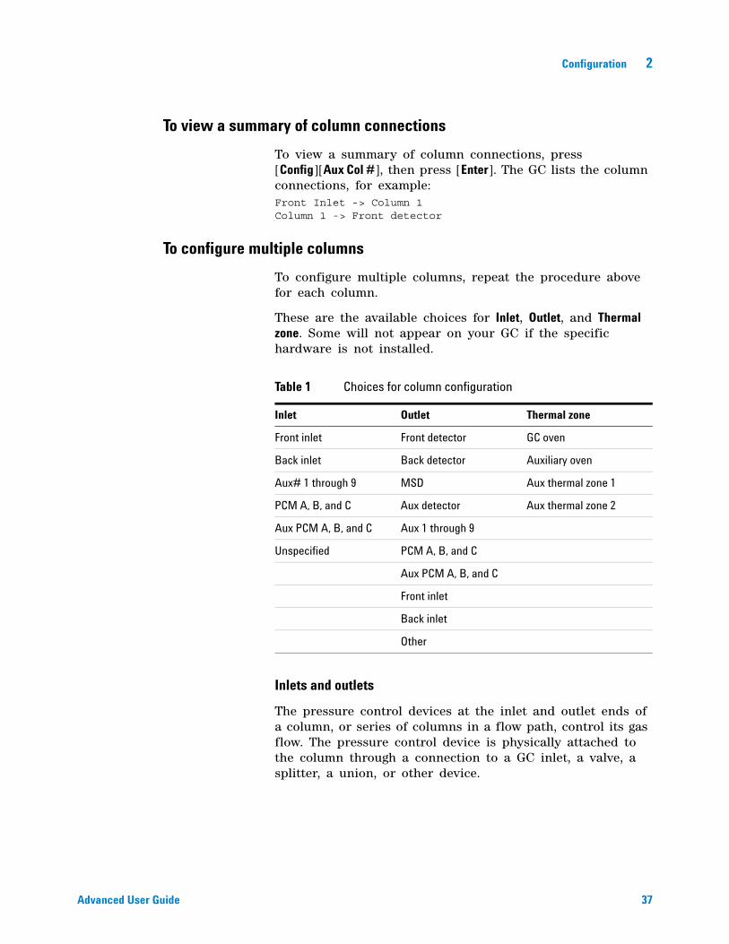
These are the available choices for Inlet, Outlet, and Thermal zone. Some will not appear on your GC if the specific hardware is not installed.
Inlets and outlets
The pressure control devices at the inlet and outlet ends of a column, or series of columns in a flow path, control its gas flow. The pressure control device is physically attached to the column through a connection to a GC inlet, a valve, a splitter, a union, or other device.
Table 1 Choices for column configuration
Inlet Outlet Thermal zone
Front inlet Front detector GC oven
Back inlet Back detector Auxiliary oven
Aux# 1 through 9 MSD Aux thermal zone 1
PCM A, B, and C Aux detector Aux thermal zone 2
Aux PCM A, B, and C Aux 1 through 9
Unspecified PCM A, B, and C
Aux PCM A, B, and C
Front inlet
Back inlet
Other
38 Advanced User Guide
2 Configuration
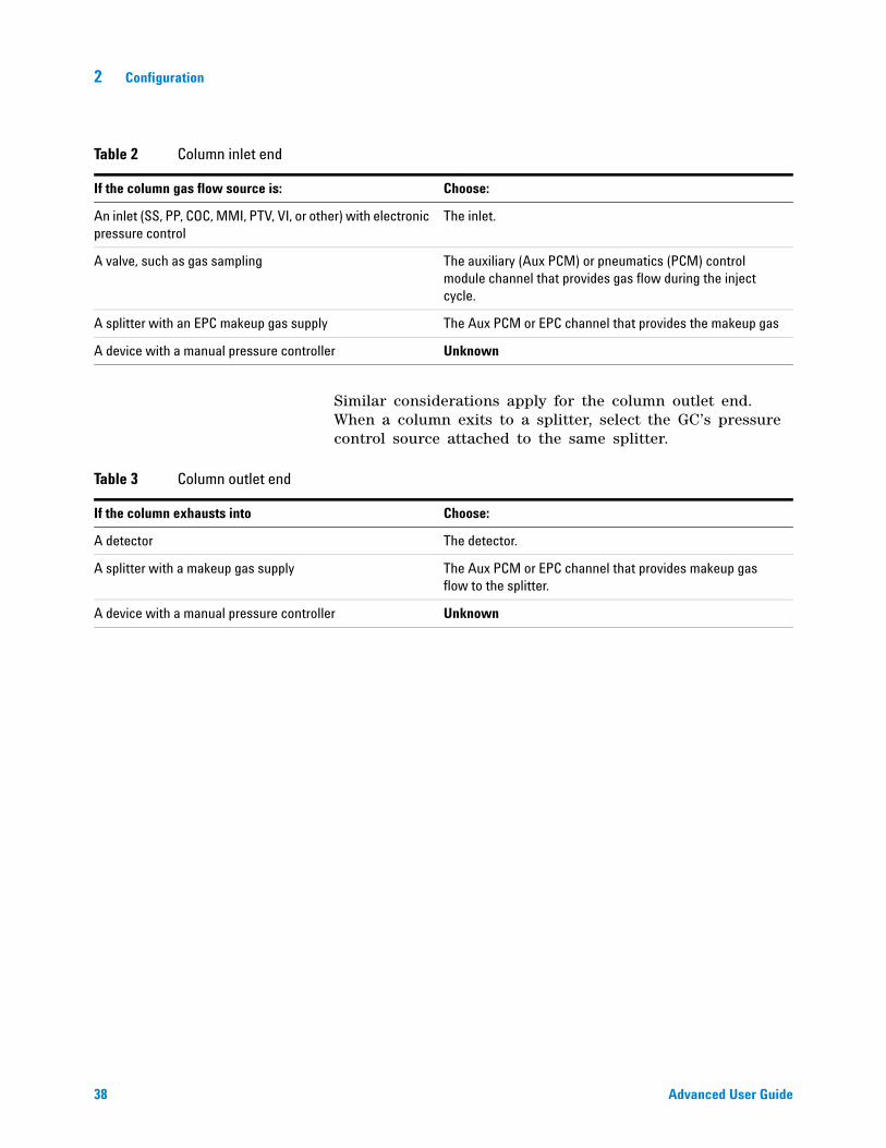
Similar considerations apply for the column outlet end. When a column exits to a splitter, select the GC’s pressure control source attached to the same splitter.
Table 2 Column inlet end
If the column gas flow source is: Choose:
An inlet (SS, PP, COC, MMI, PTV, VI, or other) with electronic pressure control
The inlet.
A valve, such as gas sampling The auxiliary (Aux PCM) or pneumatics (PCM) control module channel that provides gas flow during the inject cycle.
A splitter with an EPC makeup gas supply The Aux PCM or EPC channel that provides the makeup gas
A device with a manual pressure controller Unknown
Table 3 Column outlet end
If the column exhausts into Choose:
A detector The detector.
A splitter with a makeup gas supply The Aux PCM or EPC channel that provides makeup gas flow to the splitter.
A device with a manual pressure controller Unknown
Configuration 2
Advanced User Guide 39
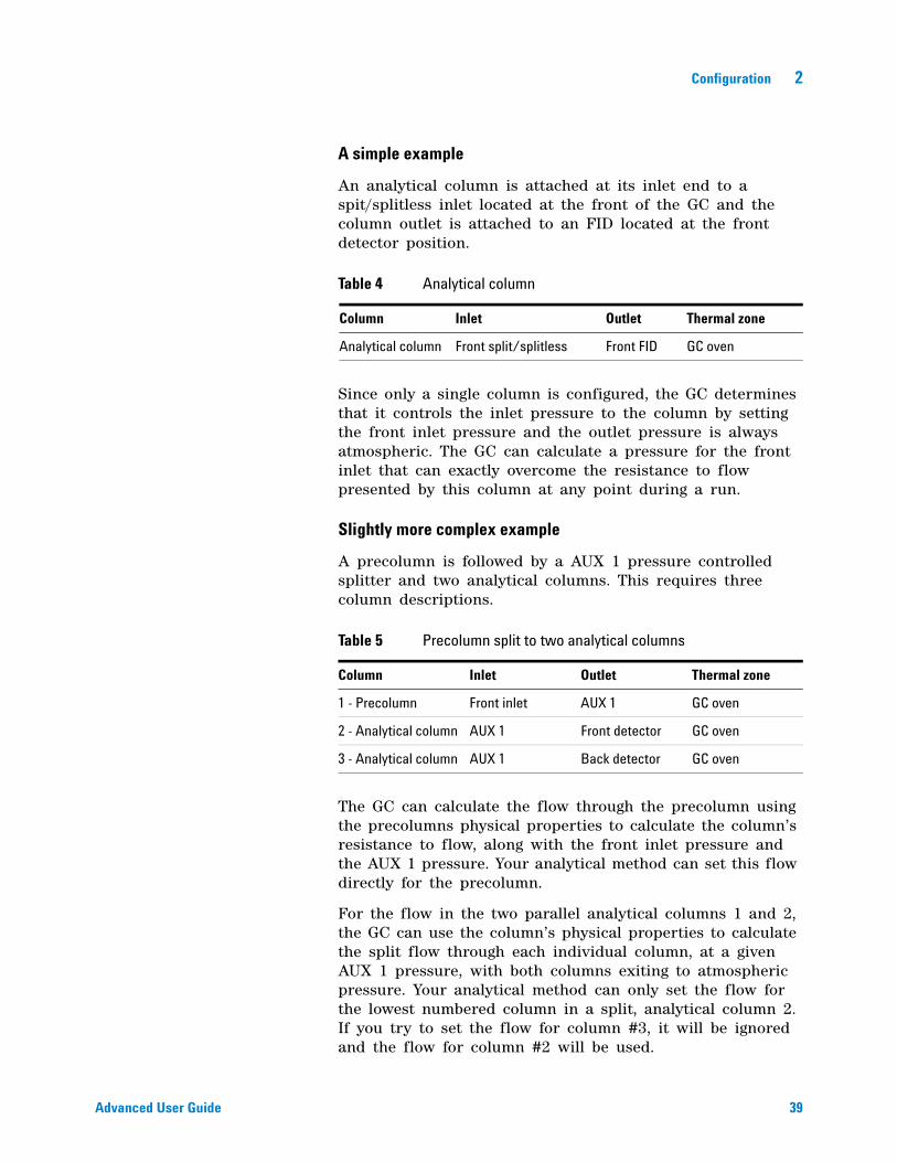
A simple example
An analytical column is attached at its inlet end to a spit/splitless inlet located at the front of the GC and the column outlet is attached to an FID located at the front detector position.
Since only a single column is configured, the GC determines that it controls the inlet pressure to the column by setting the front inlet pressure and the outlet pressure is always atmospheric. The GC can calculate a pressure for the front inlet that can exactly overcome the resistance to flow presented by this column at any point during a run.
Slightly more complex example
A precolumn is followed by a AUX 1 pressure controlled splitter and two analytical columns. This requires three column descriptions.
The GC can calculate the flow through the precolumn using the precolumns physical properties to calculate the column’s resistance to flow, along with the front inlet pressure and the AUX 1 pressure. Your analytical method can set this flow directly for the precolumn.
For the flow in the two parallel analytical columns 1 and 2, the GC can use the column’s physical properties to calculate the split flow through each individual column, at a given AUX 1 pressure, with both columns exiting to atmospheric pressure. Your analytical method can only set the flow for the lowest numbered column in a split, analytical column 2. If you try to set the flow for column #3, it will be ignored and the flow for column #2 will be used.
Table 4 Analytical column
Column Inlet Outlet Thermal zone
Analytical column Front split/splitless Front FID GC oven
Table 5 Precolumn split to two analytical columns
Column Inlet Outlet Thermal zone
1 - Precolumn Front inlet AUX 1 GC oven
2 - Analytical column AUX 1 Front detector GC oven
3 - Analytical column AUX 1 Back detector GC oven
40 Advanced User Guide
2 Configuration
If other columns are currently defined, they may not use AUX 1, Front inlet, Front detector, or Back detector in their configuration.
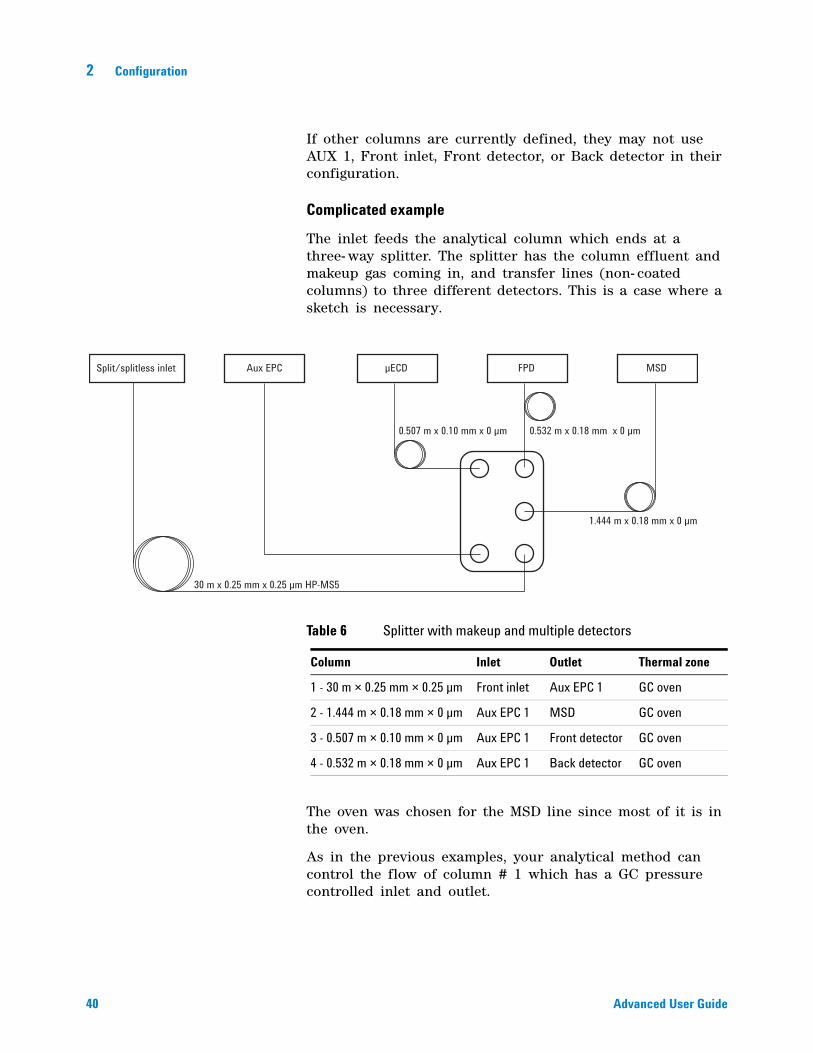
Complicated example
The inlet feeds the analytical column which ends at a three- way splitter. The splitter has the column effluent and makeup gas coming in, and transfer lines (non- coated columns) to three different detectors. This is a case where a sketch is necessary.
The oven was chosen for the MSD line since most of it is in the oven.
As in the previous examples, your analytical method can control the flow of column # 1 which has a GC pressure controlled inlet and outlet.
Split/splitless inlet
30 m x 0.25 mm x 0.25 µm HP-MS5
0.507 m x 0.10 mm x 0 µm 0.532 m x 0.18 mm x 0 µm
1.444 m x 0.18 mm x 0 µm
µECDAux EPC FPD MSD
Table 6 Splitter with makeup and multiple detectors
Column Inlet Outlet Thermal zone
1 - 30 m × 0.25 mm × 0.25 µm Front inlet Aux EPC 1 GC oven
2 - 1.444 m × 0.18 mm × 0 µm Aux EPC 1 MSD GC oven
3 - 0.507 m × 0.10 mm × 0 µm Aux EPC 1 Front detector GC oven
4 - 0.532 m × 0.18 mm × 0 µm Aux EPC 1 Back detector GC oven
Configuration 2
Advanced User Guide 41
The flows to the three detectors are based on the pressure drops through the capillaries and their resistance to flow. An Agilent flow calculator provided with the capillary flow splitter device is used to size the length and diameter of these capillary sections to obtain the desired split ratios.
Your analytical method can set the flow or pressure for column # 2, the lowest numbered column in the split. Use the value obtained from the Agilent flow calculator for this setpoint in your method.
42 Advanced User Guide
2 Configuration
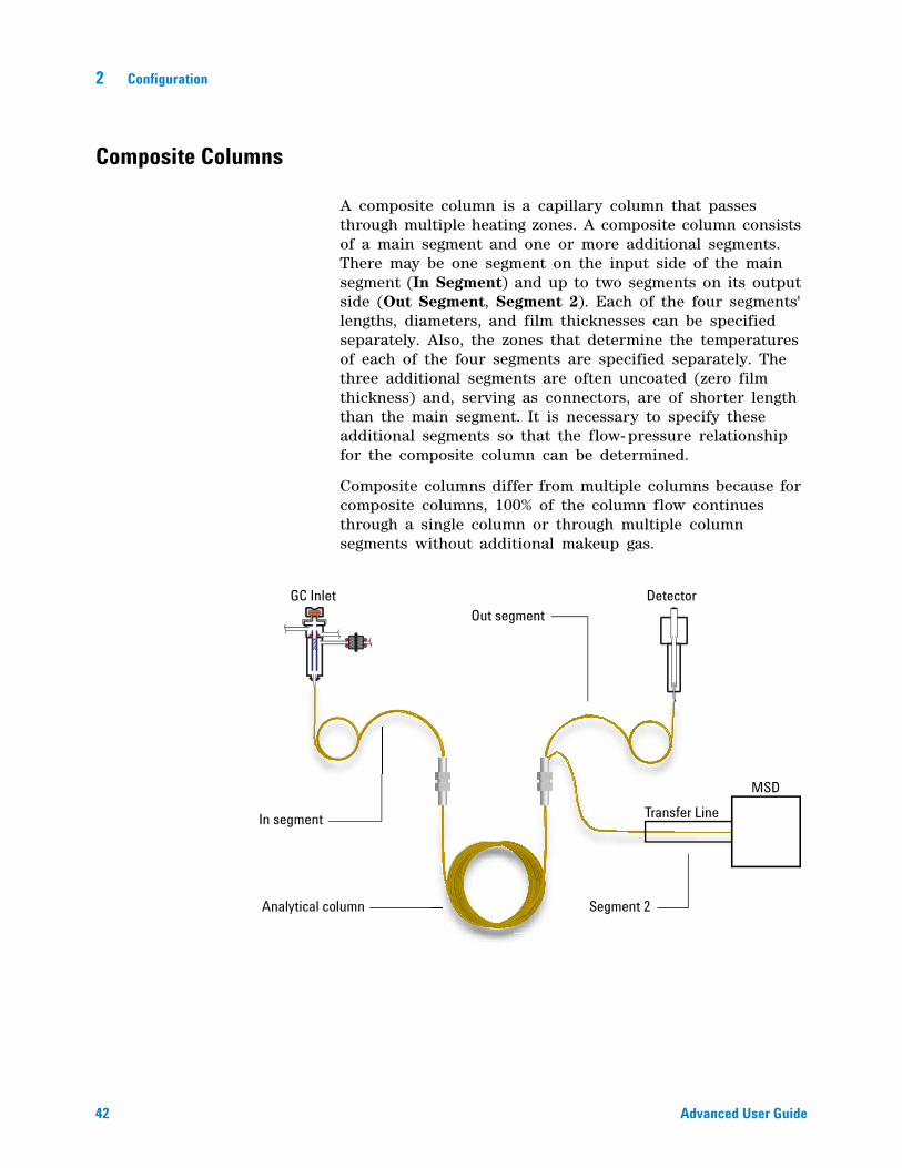
Composite Columns
A composite column is a capillary column that passes through multiple heating zones. A composite column consists of a main segment and one or more additional segments. There may be one segment on the input side of the main segment (In Segment) and up to two segments on its output side (Out Segment, Segment 2). Each of the four segments' lengths, diameters, and film thicknesses can be specified separately. Also, the zones that determine the temperatures of each of the four segments are specified separately. The three additional segments are often uncoated (zero film thickness) and, serving as connectors, are of shorter length than the main segment. It is necessary to specify these additional segments so that the flow- pressure relationship for the composite column can be determined.
Composite columns differ from multiple columns because for composite columns, 100% of the column flow continues through a single column or through multiple column segments without additional makeup gas.
Analytical column
GC Inlet Detector
MSD
Transfer LineIn segment
Out segment
Segment 2
Transfer Line
Configuration 2
Advanced User Guide 43
To configure composite columns
1 Follow steps 1- 7 on page 36.
2 If using an In Segment, scroll to In_Segment Length and enter the length, in meters. If not using an In Segment, enter 0 to disable.
3 If using an Out Segment, scroll to Out_Segment Length and enter the length, in meters. If not using an Out Segment, enter 0 to disable.
4 If using a Segment 2, scroll to Segment 2 Length and enter the length, in meters. If not using a Segment 2, enter 0 to disable.
44 Advanced User Guide
2 Configuration
LTM Columns
See “Unconfigured:” on page 27 and “Ignore Ready =” on page 26.
Low Thermal Mass (LTM) controllers and columns mount on the front door of the GC and connect to LVDS connectors [A- DET 1], [A- DET 2], or [EPC 6].
Press [Config][Aux Col #], enter the desired LTM column number [1-4], and configure as a composite column. See “Composite Columns” on page 42.
LTM Series II column modules
If using a LTM Series II column module, the GC obtains the following parameters from the column module itself during startup: primary column dimensions (length, id, film thickness, and basket size), and column maximum and absolute maximum temperatures.
Configure the column type, the In and Out segment dimensions, and so forth as needed.
Note that LTM columns can be edited only for certain parameters: column length (within a small percentage, for calibration purposes) and id (within a small percentage). Since the LTM Series II column module contains its column information, and since the column type is not changeable, changing other dimensions (for example, film thickness) does not apply.
See “Composite Columns” on page 42.
Configuration 2
Advanced User Guide 45
Cryo Trap
This discussion assumes that the trap is mounted in position B, that you use liquid nitrogen coolant and control the trap with Thermal Aux 1.
Configuration is in several parts:
• Configure the trap to the GC
• Configure a heater to the cryo trap.
• Configure the coolant.
• Configure the user- configurable heater.
• Reboot the GC.
Configure the cryo trap to the GC
1 Press [Config], then [Aux Temp #] and select Thermal Aux 1. Press [Enter].
2 Press [Mode/Type]. Scroll to Install BINLET with BV Cryo and press [Enter].
3 Press [Options], select Communications, and press [Enter]. Select Reboot GC and press [On/Yes] twice.
This informs the GC that a cryo trap is installed at position B.
Configure a heater to the cryo trap
1 Press [Config], then [Aux Temp #], select Thermal Aux 1 and press [Enter]. Select Auxiliary Type: Unknown and press [Mode/Type]. Select User Configurable Heater and press [Enter].
2 Press [Options], select Communications, and press [Enter]. Select Reboot GC and press [On/Yes] twice.
This informs the GC that the heater parameters will be supplied by the user.
Configure the coolant
The GC can handle only one type of coolant. If the coolant has already been specified for some other device, then that same coolant must be specified here.
1 Press [Config], then [Aux Temp #].
2 Select Thermal Aux 1 and press [Enter].
46 Advanced User Guide
2 Configuration
3 Scroll to Cryo Type (Valve BV).
If the value is not N2, press [Mode/Type], select N2 Cryo, press [Enter] and then [Clear].
This tells the GC what coolant will be used.
Configure the user-configurable heater
Many of the following steps tell you to reboot the GC. Ignore these requests by pressing [Clear]. Do not reboot until specifically told to do so in these instructions.
1 Press [Config] and select Aux 1. Press [Enter].
2 Enter the following control values. Press [Enter], then [Clear] after each one.
a Proportional Gain—5.30
b Integral Time—10
c Derivative Time—1.00
d Mass (Watt- sec/deg)—18
e Power (Watts)—To find the watts to set here, scroll to Back Inlet Status (BINLET). Note the watts value and enter it for this parameter.
f Cryo Control Mode—Press [Mode/Type]. The first line should already be PTV. Select Cryo Trap.
g Zone Control mode—Press [Mode/Type] and select PTV.
h Sensor—Press [Mode/Type] and select Thermocouple.
i Maximum Setpoint—400
j Maximum Programming Rate—720
Reboot the GC
Press [Options], select Communications, and press [Enter]. Select Reboot GC and press [On/Yes] twice.
Configuration 2
Advanced User Guide 47
Front Detector/Back Detector/Aux Detector/Aux Detector 2
See Ignore Ready = and “Unconfigured:” on page 27.
To configure the makeup/reference gas
The makeup gas line of your detector parameter list changes depending on your instrument configuration.
If you have an inlet with the column not defined, the makeup flow is constant. If you are operating with column defined, you have a choice of two makeup gas modes. See “About Makeup Gas” on page 312 for details.
1 Press [Config][device], where [device] is one of the following:
• [Front Det]
• [Back Det]
• [Aux detector 1]
• [Aux detector 2]
2 Scroll to Makeup gas type (or Makeup/reference gas type) and press [Mode/Type].
3 Scroll to the correct gas and press [Enter].
Lit offset
The GC monitors the difference between the detector output with the flame lit and the output when the flame is not lit. If this difference falls below the setpoint, the GC assumes that the flame has gone out and tries to reignite it. See “FID automatic reignition (Lit offset)” on page 315 for details.
To configure the FPD heaters
The flame photometric detector (FPD) uses two heaters, one in the transfer line near the base of the detector and one near the combustion chamber. When configuring the FPD heaters, select Install Detector 2 htr rather than the default Install Detector (FPD). This two heater configuration controls the detector body using the detector heated zone, and the transfer line using Thermal Aux 1 for a front detector or Thermal Aux 2 for a back detector.
48 Advanced User Guide
2 Configuration
To ignore the FID or FPD ignitor
If using an FID or FPD, you can ignite the flame manually by setting the GC to ignore the ignitor.
1 Press [Config][Front Det] or [Config][Back Det].
2 Scroll to Ignore Ignitor.
3 Press [On/Yes] to ignore the ignitor (or [Off/No] to enable the ignitor.
When Ignore Ignitor is set to True, the GC does not try to light the flame using the ignitor. The GC also completely ignores the Lit Offset setpoint and does not attempt autoignition. This means that the GC cannot determine if the flame is lit, and will not shut down the fuel gas.
WARNING In general, do not ignore the ignitor for normal operation. Ignoring the ignitor also disables the Lit Offset and autoignition features, which work together to shut down the detector if the detector flame goes out. If the flame goes out under manual ignition, GC will continue to flow hydrogen fuel gas into the detector and lab.
Use this feature only if the ignitor is defective, and only until the ignitor is repaired.
Configuration 2
Advanced User Guide 49
Analog out 1/Analog out 2
Fast peaks
The GC allows you to output analog data at two speeds. The faster speed—to be used only with the FID, FPD, and NPD—allows minimum peak widths of 0.004 minutes (8 Hz bandwidth), while the standard speed—which can be used with all detectors— allows minimum peak widths of 0.01 minutes (3.0 Hz bandwidth).
To use fast peaks:
1 Press [Config][Analog out 1] or [Config][Analog out 2].
2 Scroll to Fast peaks and press [On/Yes].
The fast peaks feature does not apply to digital output.
If you are using the fast peaks feature, your integrator must be fast enough to process data coming from the GC. Integrator bandwidth should be at least 15 Hz.
50 Advanced User Guide
2 Configuration
Valve Box
See “Unconfigured:” on page 27 and “Ignore Ready =” on page 26.
The valve box mounts on top of the column oven. It may contain up to four valves mounted on heated blocks. Each block can accommodate two valves.
Valve positions on the blocks are numbered. We suggest that valves be installed in the blocks in numeric order.
All heated valves in a valve box are controlled by the same temperature setpoint.
To assign a GC power source to a valve box heater
1 Unlock the GC configuration, press the [Options] key, select Keyboard & Display and press the [Enter] key. Scroll down to Hard Configuration Lock and press the [off] button.
2 Press [Config], scroll to Valve Box and press [Enter].
3 With Unconfigured selected, press [Mode/type], select one of the following and press [Enter].
• Install heater A1 - for a valve box containing a single heater plugged into the connector labeled A1 on the valve box bracket.
• Install Heater A2 - for a valve box containing a single heater plugged into the connector labeled A2 on the valve box bracket.
• Install 2 htr A1 & A2 - for a valve box containing two heaters plugged into the connectors labeled AI and A2 on the valve box bracket.
The valve box bracket is located inside the GC right side electrical compartment in the upper right location.
4 When prompted by the GC, turn the power off then on again.
This completes the configuration of the valve box. To set the valve box temperature for your method press the [valve #] key, and scroll to Valve Box.
Configuration 2
Advanced User Guide 51
Thermal Aux
See “Unconfigured:” on page 27 and “Ignore Ready =” on page 26.
The auxiliary thermal controllers provide up to three channels of temperature control. These controllers are labeled Thermal Aux 1, Thermal Aux 2, and Thermal Aux 3.
To assign a GC power source to an Aux thermal zone
Devices such as valve boxes and transfer lines have heaters which can be plugged into one of several connectors on the GC. Before use, you must configure these devices so that the GC knows the type of device plugged into the connector (inlet heater, detector heater, transfer line heater, and so on) and how to control it.
This procedure assigns the heater power source to the Thermal Aux 1, Thermal Aux 2, or Thermal Aux 3 temperature control zone.
1 Unlock the GC configuration. Press [Options], select Keyboard & Display and press [Enter]. Scroll down to Hard Configuration Lock and press [Off/No].
2 Press [Config][Aux Temp #] and scroll to Thermal Aux 1, Thermal Aux 2, or Thermal Aux 3 and press [Enter].
3 With Unconfigured selected, press [Mode/Type], and select:
• Install Heater A1 to configure a valve box heater plugged into the valve box bracket plug labeled A1.
• Install Heater A2 to configure a valve box heater plugged into the valve box bracket plug labeled A2.
• If installing a transfer line, scroll to the line which describes the transfer line type (MSD Transfer, Ion Trap GCHI, RIS Transfer, and so on) and its GC connector (F-DET, A1, BINLET, and so on). For example, for an MSD transfer line connected to A1, select MSD Transfer A1.
4 Press [Enter] after making the selection.
5 When prompted by the GC, turn the power off then on again.
52 Advanced User Guide
2 Configuration
For devices such as a valve box, inlet, or detector, configuration is complete. For other devices, next configure the specific device type:
1 Unlock the GC configuration. Press [Options], select Keyboard & Display and press [Enter]. Scroll down to Hard Configuration Lock and press [Off/No].
2 Press [Config][Aux Temp #] and scroll to Thermal Aux 1, Thermal Aux 2, or Thermal Aux 3 and press [Enter].
3 Scroll to Auxiliary type, press [Mode/Type], scroll to and select the desired device type, and press [Enter]. Types may include:
• Cryo focus
• Cryo trap
• AED transfer line
• Nickel catalyst
• ICMPS argon preheat
• ICMPS transfer line
• ICPMS injector
• Ion Trap GC Heated Interface
• G3520 Transfer Line
• MSD transfer line
• User Configurable
To configure a MSD transfer line heater
1 Check that a power source for the MSD heater was assigned. See “To assign a GC power source to an Aux thermal zone” on page 51.
2 Press [Config][Aux Temp #] and scroll to Thermal Aux 1, Thermal Aux 2, or Thermal Aux 3 depending on where the MSD heater was assigned, and press [Enter].
3 Scroll to Auxiliary type, press [Mode/Type], scroll to and select the MSD transfer line, and press [Enter].
To configure a nickel catalyst heater
1 Check that a power source for the Nickel Catalyst heater was assigned. See “To assign a GC power source to an
Configuration 2
Advanced User Guide 53
Aux thermal zone” on page 51.
2 Press [Config][Aux Temp #] and scroll to Thermal Aux 1, Thermal Aux 2, or Thermal Aux 3 depending on where the Nickel Catalyst heater was assigned, and press [Enter].
3 Scroll to Auxiliary type, press [Mode/Type], scroll to and select Nickel catalyst, and press [Enter].
To configure an AED transfer line heater
1 Check that a power source for the AED transfer line heater was assigned. See “To assign a GC power source to an Aux thermal zone” on page 51.
2 Press [Config][Aux Temp #] and scroll to Thermal Aux 1, Thermal Aux 2, or Thermal Aux 3 depending on where the AED transfer line heater was assigned, and press [Enter].
3 Scroll to Auxiliary type, press [Mode/Type], scroll to and select the AED transfer line, and press [Enter].
To configure an ion trap transfer line heater
1 Check that a power source for the ion trap transfer line heater was assigned. See “To assign a GC power source to an Aux thermal zone” on page 51.
2 Press [Config][Aux Temp #] and scroll to Thermal Aux 1, Thermal Aux 2, or Thermal Aux 3 depending on where the ion trap transfer line heater was assigned, and press [Enter].
3 Scroll to Auxiliary type, press [Mode/Type], scroll to and select Ion Trap GC Heated Interface, and press [Enter].
54 Advanced User Guide
2 Configuration
PCM A/PCM B/PCM C
See “Unconfigured:” on page 27 and “Ignore Ready =” on page 26.
A pressure control module (PCM) provides two channels of gas control.
Channel 1 is a simple forward- pressure regulator that maintains a constant pressure at its output. With a fixed downstream restrictor, it provides constant flow.
Channel 2 is more versatile. With the normal flow direction (in at the threaded connector, out via the coiled tubing), it is similar to channel 1. However with the flow direction reversed (some extra fittings will be needed), it becomes a back- pressure regulator that maintains a constant pressure at its inlet.
Thus channel 2 (reversed) behaves as a controlled leak. If the inlet pressure drops below setpoint, the regulator closes down. If inlet pressure rises above setpoint, the regulator bleeds off gas until the pressure returns to setpoint.
To assign a GC communication source to a PCM
1 Unlock the GC configuration, press [Options], select Keyboard & Display and press [Enter]. Scroll down to Hard Configuration Lock and press [Off/No].
2 Press [Config][Aux EPC #], scroll to a PCMx and press [Enter].
3 With Unconfigured selected, press [Mode/Type], select Install EPCx and press [Enter].
4 When prompted by the GC, turn the power off then on again.
To configure the other parameters on this PCM, see To configure a PCM.
To configure a PCM
1 Press [Config][Aux EPC #], scroll to the PCMx and press [Enter].
2 Scroll to Gas type, press [Mode/Type], make a selection and press [Enter].
Configuration 2
Advanced User Guide 55
This completes configuration for Channel 1. The rest of the entries refer to Channel 2.
3 Scroll to Aux gas type, press [Mode/Type], make a selection and press [Enter].
4 Scroll to Aux Mode:, press [Mode/Type], select one of the following and press [Enter]:
• Forward Pressure Control - Aux channel
• Back Pressure Control- Aux channel
For a definition of these terms see “Pressure Control Modules” on page 168.
The pressure control mode for the main channel is set by pressing [Aux EPC #]. Select Mode:, press [Mode/Type], select the mode and press [Enter].

56 Advanced User Guide
2 Configuration
Pressure aux 1,2,3/Pressure aux 4,5,6/Pressure aux 7,8,9
See Ignore Ready = and “Unconfigured:” on page 27.
An auxiliary pressure controller provides three channels of forward- pressure regulation. Three modules can be installed for a total of nine channels.
The numbering of the channels depends on where the controller is installed. See “Auxiliary Pressure Controllers” on page 171 for details. Within a single module, channels are numbered from left to right (as seen from the back of the GC) and are labeled on the AUX EPC module.
To assign a GC communication source to an Aux EPC
1 Unlock the GC configuration, press [Options], select Keyboard & Display and press [Enter]. Scroll down to Hard Configuration Lock and press [Off/No].
2 Press [Config][Aux EPC #], select Aux EPC 1,2,3 or Aux EPC 4,5,6 or Aux EPC 7,8,9 and press [Enter].
3 With Unconfigured selected, press [Mode/Type], select Install EPCx and press [Enter].
4 When prompted by the GC, turn the power off then on again.
To configure the other parameters on this EPC, see To configure an auxiliary pressure channel.
To configure an auxiliary pressure channel
1 Press [Config][Aux EPC #], select Aux EPC 1,2,3 or Aux EPC 4,5,6 or Aux EPC 7,8,9 and press [Enter].
2 Select Chan x Gas type, press [Mode/Type], select the gas that is plumbed to the channel and press [Enter].
3 If necessary, repeat the above step for the other two channels on this EPC module.
Configuration 2
Advanced User Guide 57
Status
The [Status] key has two tables associated with it. You switch between them by pressing the key.
The Ready/Not Ready status table
This table lists parameters that are Not Ready or gives you a Ready for Injection display. If there are any faults, warnings, or method mismatches present, they are displayed here.
The setpoint status table
This table lists setpoints compiled from the active parameter lists on the instrument. This is a quick way to view active setpoints during a run without having to open multiple lists.
To configure the setpoint status table
You can change the order of the list. You might want the three most important setpoints to appear in the window when you open the table.
1 Press [Config][Status].
2 Scroll to the setpoint that should appear first and press [Enter]. This setpoint will now appear at the top of the list.
3 Scroll to the setpoint that should appear second and press [Enter]. This setpoint will now be the second item on the list.
4 And so on, until the list is in the order you wish.
58 Advanced User Guide
2 Configuration
Time
Press [Time] to open this function. The first line always displays the current date and time, and the last line always displays a stopwatch. The two middle lines vary:
Between runs Show last and next (calculated) run times.
During a run Show time elapsed and time remaining in the run.
During Post Run Show last run time and remaining Post Run time.
To set time and date
1 Press [Config][Time].
2 Select Time zone (hhmm) and enter the local time offset from GMT using a 24 hour format.
3 Select Time (hhmm) and enter the local time.
4 Select Date (ddmmyy) and enter the date.
To use the stopwatch
1 Press [Time].
2 Scroll to the time= line.
3 To begin the timed period press [Enter].
4 To stop the timed period press [Enter].
5 Press [Clear] to reset the stopwatch.
Configuration 2
Advanced User Guide 59
Valve #
Up to 4 valves can be mounted in a temperature- controlled valve box and are normally wired to the valve box bracket V1 through V4 plugs, located inside the electrical compartment. Additional valves or other devices (4 through 8) can be wired using the plug labeled EVENT on the back of the GC.
To configure a valve
1 Press [Config][Valve #] and enter the number (1 to 8) of the valve you are configuring. The current valve type is displayed.
2 To change the valve type, press [Mode/Type], select the new valve type, and press [Enter].
Valve types
• Sampling Two- position (load and inject) valve. In load position, an external sample stream flows through an attached (gas sampling) or internal (liquid sampling) loop and out to waste. In inject position, the filled sampling loop is inserted into the carrier gas stream. When the valve switches from Load to Inject, a run starts if one is not already in progress. See the example in “Gas sampling valve” on page 360.
• Switching Two- position valve with four, six, or more ports. These are general- purpose valves used for such tasks as column selection, column isolation, and many others. For an example of valve control, see “Simple valve: column selection” on page 359.
• Multiposition Also called a stream selection valve. It selects one from a number of gas streams and feeds it to a sampling valve. The actuator may be ratchet- (advances the valve one position each time it is activated) or motor- driven. An example that combines a stream selection valve with a gas sampling valve is on page 361.
• Remote start Available selection when configuring valve #7 or #8 only. Use this selection when wires controlling an external device are attached to an internal pair of contacts controlled by the GC.
• Other Something else.
• Not installed Self- explanatory.
60 Advanced User Guide
2 Configuration
Front injector/Back injector
The GC supports three models of samplers.
For the 7693A and 7650A samplers, the GC recognizes which injector is plugged into which connector, INJ1 or INJ2. No configuration is needed. To move an injector from one inlet to another requires no settings: the GC detects the injector position.
To configure the 7693A sampler system, see the 7693A Installation, Operation, and Maintenance manual. To configure the 7650A sampler system, see the 7650A Installation, Operation, and Maintenance manual.
For the 7683 series samplers, normally the front inlet’s injector is plugged into the connection on the rear of the GC labeled INJ1. The rear inlet’s injector is plugged into the connection on the rear of the GC labeled INJ2.
When a GC shares a single 7683 injector between two inlets, the injector is moved from one inlet to the other and the injector’s plug- in on the rear of the GC is switched.
To move the 7683 injector from one inlet on the GC to another without changing the injector’s plug- in, use the Front/Back tower parameter. See “To move a 7683 injector between front and back positions” on page 61.
Solvent Wash Mode (7683 ALS)
This section applies to the 7683 ALS system. To configure the 7693A sampler system, see the 7693A Installation, Operation, and Maintenance manual.
Depending upon the installed injector and turret, these parameters may be available to configure multiple solvent wash bottles usage. If necessary, refer to your injector user documentation for details.
A, B—Use solvent bottle A if injector uses solvent A washes and solvent bottle B if injector uses solvent B washes.
A-A2, B-B2—Use solvent bottles A and A2 if injector uses solvent A washes and solvent bottles B and B2 if injector uses solvent B washes. The injector alternates between both bottles.
Configuration 2
Advanced User Guide 61
A-A3, B-B3—Use solvent bottles A, A2, and A3 if injector uses solvent A washes and solvent bottles B, B2, and B3 if injector uses solvent B washes. The injector alternates between all bottles.
To configure an injector (7683 ALS)
This section applies to the 7683 ALS system. To configure the 7693A sampler system, see the 7693A Installation, Operation, and Maintenance manual. To configure the 7650A sampler system, see the 7650A Installation, Operation, and Maintenance manual.
1 Press [Config][Front Injector] or [Config][Back Injector].
2 Scroll to Front/Back tower.
3 Press [Off/No] to change the present tower position from INJ1 to INJ2 or from INJ2 to INJ1.
4 If the installed turret has locations for multiple solvent bottles, scroll to Wash Mode, press [Mode/Type], and then select 1, 2, or 3 bottles for each solvent and press [Enter].
5 Scroll to [Syringe size]. Enter the size of the syringe that is installed and press [Enter].
To move a 7683 injector between front and back positions
This section applies only to the 7683 ALS system. (The 7693A system automatically determines the current injector location.)
If only one injector is installed on the GC, move it from the front to back inlet and reconfigure the GC as described below:
1 Press [Config][Front Injector] or [Config][Back Injector].
2 Scroll to Front/Back tower.
3 Press [Off/No] to change the present tower position from INJ1 to INJ2 or from INJ2 to INJ1.
If you press [Config], then scroll down, you will see that the only configurable injector is now in the other position.
4 Lift the injector and place it over the mounting post for the other inlet.
62 Advanced User Guide
2 Configuration
Sample tray (7683 ALS)
This section applies to the 7683 ALS system. To configure the 7693A sampler system, see the 7693A Installation, Operation, and Maintenance manual.
1 Press [Config][Sample Tray].
2 If the vial gripper is touching vials either too high or too low for reliable pickup, scroll to Grip offset and press [Mode/Type] to select:
• Up to increase the gripper arm pickup height
• Default
• Down to decrease the gripper arm pickup height
3 Scroll to Bar Code Reader.
4 Press [On/Yes] or [Off/No] to control the following bar code setpoints:
• Enable 3 of 9—encodes both letters and numbers, plus a few punctuation marks, and message length can be varied to suit both the amount of data to be encoded and the space available
• Enable 2 of 5—restricted to numbers but does allow variable message length
• Enable UPC code—restricted to numbers- only with fixed message length
• Enable checksum—verifies that the checksum in the message matches the checksum calculated from the message characters, but does not include the checksum character in the returned message
5 Enter 3 as the BCR Position when the reader is installed in the front of the tray. Positions 1–19 are available.
Configuration 2
Advanced User Guide 63
Instrument
1 Press [Config]. Scroll to Instrument and press [Enter].
2 Scroll to Serial #. Enter a serial number and press [Enter]. This function can only be done by Agilent service personnel.
3 Scroll to Auto prep run. Press [On/Yes] to enable Auto prep run, [Off/No] to disable it. See “Pre Run and Prep Run” on page 184 for details.
4 Scroll to Zero Init Data Files.
• Press [On/Yes] to enable it. When it is On, the GC immediately begins to subtract the current detector output from all future values. This applies only to digital output, and is useful when a non- Agilent data system has problems with baseline data that is non- zero.
• Press [Off/No] to disable it. This is appropriate for all Agilent data systems.
5 Front inlet type: and Back inlet type: are both information displays. The values are determined by the type of flow modules installed.
6 The Oven line displays the GC power configuration.
7 Press [Clear] to return to the Config menu or any other function to end.

64 Advanced User Guide
2 Configuration
65
Agilent 7890A Gas ChromatographAdvanced User Guide
Agilent Technologies
3Options
About Options 66
Calibration 67
Maintaining EPC calibration—inlets, detectors, PCM, and AUX 67
Auto zero septum purge 68
Auto flow zero 67
Zero conditions 68
Zero intervals 68
To zero a specific flow or pressure sensor 68
To zero all pressure sensors in all modules 69
Column calibration 69
Communication 73
Configuring the IP address for the GC 73
Keyboard and Display 74
66 Advanced User Guide
3 Options
About Options
The [Options] key is used for a group of functions that are usually set on installation and seldom changed afterward. It accesses this menu:
Calibration
Communication
Keyboard and Display
Options 3
Advanced User Guide 67
Calibration
Press [Calibration] to list the parameters that can be calibrated. These include:
• Inlets
• Detectors
• ALS
• Columns
• Oven
• Atmospheric pressure
In general, you will only need to calibrate the EPC modules and capillary columns. ALS, oven, and atmospheric pressure calibration should only be performed be trained service personnel.
The calibration displays are discussed in the Agilent 7890A Service Manual.
Maintaining EPC calibration—inlets, detectors, PCM, and AUX
The EPC gas control modules contain flow and/or pressure sensors that are calibrated at the factory. Sensitivity (slope of the curve) is quite stable, but zero offset requires periodic updating.
Flow sensors
The split/splitless and purged packed inlet modules use flow sensors. If the Auto flow zero feature (see page 67) is on, they are zeroed automatically after each run. This is the recommended way. They can also be zeroed manually—see “To zero a specific flow or pressure sensor.”
Pressure sensors
All EPC control modules use pressure sensors. They can be zeroed as a group or individually. There is no automatic zero for pressure sensors.
Auto flow zero
A useful calibration option is Auto flow zero. When it is On, after the end of a run the GC shuts down the flow of gases to an inlet, waits for the flow to drop to zero, measures and
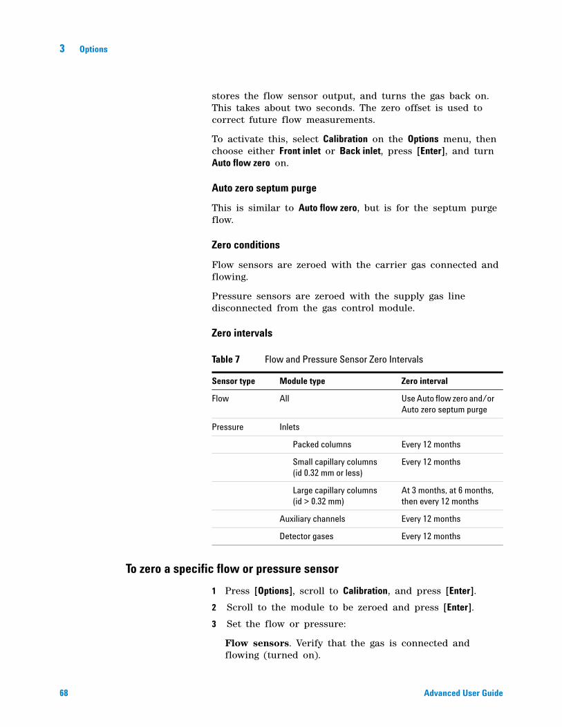
68 Advanced User Guide
3 Options
stores the flow sensor output, and turns the gas back on. This takes about two seconds. The zero offset is used to correct future flow measurements.
To activate this, select Calibration on the Options menu, then choose either Front inlet or Back inlet, press [Enter], and turn Auto flow zero on.
Auto zero septum purge
This is similar to Auto flow zero, but is for the septum purge flow.
Zero conditions
Flow sensors are zeroed with the carrier gas connected and flowing.
Pressure sensors are zeroed with the supply gas line disconnected from the gas control module.
Zero intervals
To zero a specific flow or pressure sensor
1 Press [Options], scroll to Calibration, and press [Enter].
2 Scroll to the module to be zeroed and press [Enter].
3 Set the flow or pressure:
Flow sensors. Verify that the gas is connected and flowing (turned on).
Table 7 Flow and Pressure Sensor Zero Intervals
Sensor type Module type Zero interval
Flow All Use Auto flow zero and/or Auto zero septum purge
Pressure Inlets
Packed columns Every 12 months
Small capillary columns (id 0.32 mm or less)
Every 12 months
Large capillary columns (id > 0.32 mm)
At 3 months, at 6 months, then every 12 months
Auxiliary channels Every 12 months
Detector gases Every 12 months
Options 3
Advanced User Guide 69
Pressure sensors. Disconnect the gas supply line at the back of the GC. Turning it off is not adequate; the valve may leak.
4 Scroll to the desired zero line.
5 Press [On/Yes] to zero or [Clear] to cancel.
6 Reconnect any gas line disconnected in step 3 and restore operating flows
To zero all pressure sensors in all modules
1 Press [Service Mode], scroll to Diagnostics, and press [Enter].
2 Scroll to Electronics and press [Enter].
3 Scroll to Pneumatics and press [Enter].
4 Disconnect the gas supply lines at the back of the GC. (Turning them off is not adequate; the valves may leak.)
5 Scroll to Zero all pressure sensors.
6 Press [On/Yes] to zero or [Clear] to cancel.
7 Reconnect all gas supply lines and restore operating pressures.
Column calibration
As you use a capillary column, you may occasionally trim off portions, changing the column length. If measuring the actual length is impractical, and if you are using EPC with a defined column, you can use an internal calibration routine to estimate the actual column length. Similarly, if you do not know the column internal diameter or believe it is inaccurate, you can estimate the diameter from related measurements.
Before you can calibrate the column, make sure that:
• You are using a capillary column
• The column is defined
• There are no oven ramps
• The column gas source (usually the inlet) is On and non- zero
Also note that column calibration fails if the calculated column length correction is > 5 m, or if the calculated diameter correction is > 20 μm.
70 Advanced User Guide
3 Options
Calibration modes
There are three ways to calibrate the column length and/or diameter:
• Calibrate using an actual measured column flow rate
• Calibrate using an unretained peak time (elution time)
• Calibrate both length and diameter using flow rate and elution time
To estimate the actual column length or diameter from an elution time
1 Set oven ramp 1 to 0.00, then verify that the column is defined.
2 Perform a run using an unretained compound and record the elution time.
3 Press [Options], scroll to Calibration and press [Enter].
4 From the calibration list, select the column and press [Enter]. The GC displays the current calibration mode for the column.
5 To recalibrate or to change calibration mode, press [Mode/Type] to see the column calibration mode menu.
6 Scroll to Length or Diameter and press [Enter]. The following choices appear:
• Mode
• Measured flow
• Unretained peak
• Calculated length or Calculated diameter
• Not calibrated
7 Scroll to Unretained peak and enter the actual elution time from the run performed above.
8 When you press [Enter], the GC will estimate the column length or diameter based on the elution time input and will now use that data for all calculations.
CAUTION When you measure the column flow rate, be sure to convert the measurement to normal temperature and pressure if your measurement device does not report data at NTP. If you enter uncorrected data, the calibration will be wrong.
Options 3
Advanced User Guide 71
To estimate the actual column length or diameter from the measured flow rate
1 Set oven ramp 1 to 0.00, then verify that the column is defined.
2 Set the oven, inlet, and detectors temperatures to 35 °C and allow them to cool to room temperature.
3 Remove the column from the detector.
4 Measure the actual flow rate through the column using a bubble meter. Record the value. Reinstall the column.
5 Press [Options], scroll to Calibration and press [Enter].
6 From the calibration list, select the column and press [Enter]. The GC displays the current calibration mode for the column.
7 To recalibrate or to change calibration mode, press [Mode/Type] to see the column calibration mode menu.
8 Scroll to Length or Diameter and press [Enter]. The following choices appear:
• Mode
• Measured flow
• Unretained peak
• Calculated length or Calculated diameter
• Not calibrated
9 Scroll to Measured flow and enter the corrected column flow rate (in mL min) from the run performed above.
10 When you press [Enter], the GC will estimate the column length or diameter based on the elution time input and will now use that data for all calculations.
To estimate the actual column length and diameter
1 Set oven ramp 1 to 0.00, then verify that the column is defined.
2 Perform a run using an unretained compound and record the elution time.
CAUTION When you measure the column flow rate, be sure to convert the measurement to normal temperature and pressure if your measurement device does not report data at NTP. If you enter uncorrected data, the calibration will be wrong.
72 Advanced User Guide
3 Options
3 Set the oven, inlet, and detectors temperatures to 35 °C and allow them to cool to room temperature.
4 Remove the column from the detector.
5 Measure the actual flow rate through the column using a bubble meter. Record the value. Reinstall the column.
6 Press [Options], scroll to Calibration and press [Enter].
7 From the calibration list, select the column and press [Enter]. The GC displays the current calibration mode for the column.
8 To recalibrate or to change calibration mode, press [Mode/Type] to see the column calibration mode menu.
9 Scroll to Length & diameter and press [Enter]. The following choices appear:
• Mode
• Measured flow
• Unretained peak
• Calculated length
• Calculated diameter
• Not calibrated
10 Scroll to Measured flow and enter the corrected column flow rate (in mL min) from the run performed above.
11 Scroll to Unretained peak and enter the actual elution time from the run performed above.
12 When you press [Enter], the GC will estimate the column length or diameter based on the elution time input and will now use that data for all calculations.
CAUTION When you measure the column flow rate, be sure to convert the measurement to normal temperature and pressure if your measurement device does not report data at NTP. If you enter uncorrected data, the calibration will be wrong.
Options 3
Advanced User Guide 73
Communication
Configuring the IP address for the GC
For network (LAN) operation, the GC needs an IP address. It can get this from a DHCP server, or it can be entered directly from the keyboard. In either case, see your LAN administrator.
To use a DHCP server
1 Press [Options]. Scroll to Communications and press [Enter].
2 Scroll to Enable DHCP and press [On/Yes]. When prompted, turn the GC off and then on again.
To set the LAN address at the keyboard
1 Press [Options]. Scroll to Communications and press [Enter].
2 Scroll to Enable DHCP and, if necessary, press [Off/No]. Scroll to Reboot GC. Press [On/Yes] and [On/Yes].
3 Press [Options]. Scroll to Communications and press [Enter].
4 Scroll to IP. Enter the numbers of the GC IP address, separated by dots, and press [Enter]. A message tells you to power cycle the instrument. Do not power cycle yet. Press [Clear].
5 Scroll to GW. Enter the Gateway number and press [Enter]. A message tells you to power cycle the instrument. Do not power cycle yet. Press [Clear].
6 Scroll to SM and press [Mode/Type]. Scroll to the appropriate subnet mask from the list given and press [Enter]. A message tells you to power cycle the instrument. Do not power cycle yet. Press [Clear].
7 Scroll to Reboot GC. Press [On/Yes] and [On/Yes] to power cycle the instrument and apply the LAN setpoints.
74 Advanced User Guide
3 Options
Keyboard and Display
Press [Options] and scroll to Keyboard and Display. Press [Mode/Type].
The following parameters are turned on and off by pressing the [On/Yes] or [Off/No] keys.
Keyboard lock These keys and functions are operational when the keyboard lock is On:
[Start], [Stop], and [Prep Run]
[Load][Method] and [Load][Seq]
[Seq]—to edit existing sequences
[Seq Control]—to start or stop sequences.
When Keyboard lock is On, other keys and functions are not operational. Note that an Agilent data system can independently lock the GC keyboard. To edit GC setpoints using the GC keyboard, turn off both the GC keyboard lock and the data system keyboard lock.
Hard configuration lock On prevents keyboard configuration changes; Off removes lock.
Key click Click sound when keys are pressed.
Warning beep Allows you to hear warning beeps.
Warning beep mode There are 9 different warning sounds that may be selected. This allows you to give multiple GCs individual “voices”. We suggest you experiment.
Method modified beep Turn on for high pitched beep when method setpoint is modified.
Press [Mode/Type] to change the pressure units and radix type.
Pressure units psi—pounds per square inch, lb/in2
bar—absolute cgs unit of pressure, dyne/cm2
kPa—mks unit of pressure, 103 N/m2
Language Select English or Chinese.

Options 3
Advanced User Guide 75
Radix type Determines the numeric separator type—1.00 or 1,00
Display saver If On, dims the display after a period of inactivity. If Off, disabled.

76 Advanced User Guide
3 Options
77
Agilent 7890A Gas ChromatographAdvanced User Guide
Agilent Technologies
4 Chromatographic Checkout
About Chromatographic Checkout 78
To Prepare for Chromatographic Checkout 79
To Check FID Performance 81
To Check TCD Performance 86
To Check NPD Performance 91
To Check uECD Performance 96
To Check FPD Performance (Sample 5188-5953) 101
To Verify FPD Performance (Sample 5188-5245, Japan) 108
78 Advanced User Guide
4 Chromatographic Checkout
About Chromatographic Checkout
The tests described in this section provide basic confirmation that the GC and detector can perform comparably to factory condition. However, as detectors and the other parts of the GC age, detector performance can change. The results presented here represent typical outputs for typical operating conditions and are not specifications.
The tests assume the following:
• Use of an automatic liquid sampler. If not available, use a suitable manual syringe instead of the syringe listed.
• Use of a 10- µL syringe in most cases. However, a 5- µL syringe is an acceptable substitute for the 1- µL injections described here.
• Use of the septa and other hardware (liners, jets, adapters, and so forth) described. If you substitute other hardware, performance can vary.
Selected tests described in this section can be run automatically using the documentation and utility DVD provided with your GC.
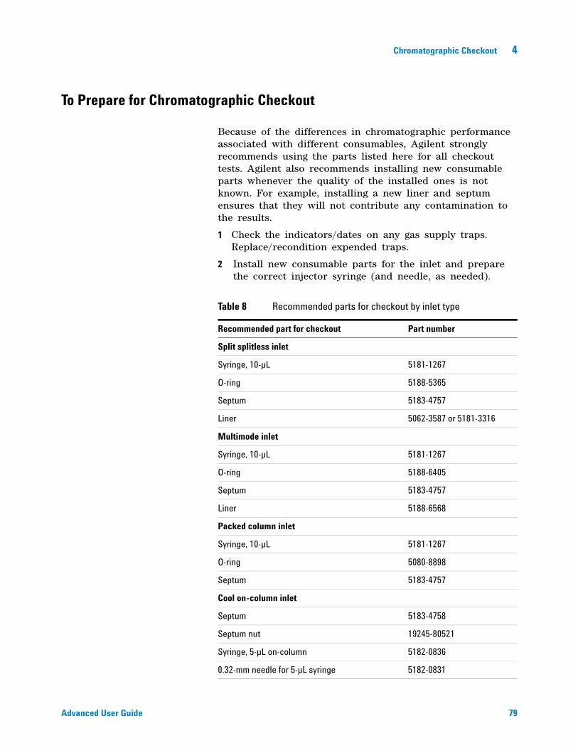
Chromatographic Checkout 4
Advanced User Guide 79
To Prepare for Chromatographic Checkout
Because of the differences in chromatographic performance associated with different consumables, Agilent strongly recommends using the parts listed here for all checkout tests. Agilent also recommends installing new consumable parts whenever the quality of the installed ones is not known. For example, installing a new liner and septum ensures that they will not contribute any contamination to the results.
1 Check the indicators/dates on any gas supply traps. Replace/recondition expended traps.
2 Install new consumable parts for the inlet and prepare the correct injector syringe (and needle, as needed).
Table 8 Recommended parts for checkout by inlet type
Recommended part for checkout Part number
Split splitless inlet
Syringe, 10-µL 5181-1267
O-ring 5188-5365
Septum 5183-4757
Liner 5062-3587 or 5181-3316
Multimode inlet
Syringe, 10-µL 5181-1267
O-ring 5188-6405
Septum 5183-4757
Liner 5188-6568
Packed column inlet
Syringe, 10-µL 5181-1267
O-ring 5080-8898
Septum 5183-4757
Cool on-column inlet
Septum 5183-4758
Septum nut 19245-80521
Syringe, 5-µL on-column 5182-0836
0.32-mm needle for 5-µL syringe 5182-0831
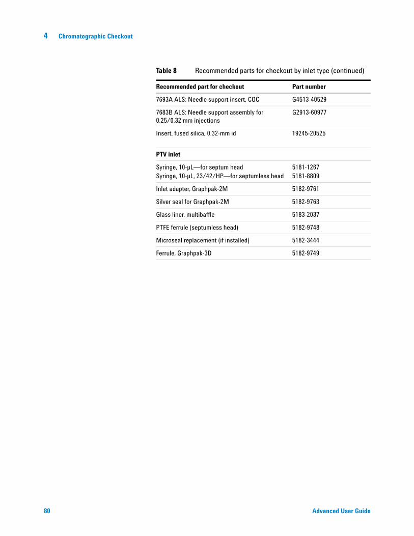
80 Advanced User Guide
4 Chromatographic Checkout
7693A ALS: Needle support insert, COC G4513-40529
7683B ALS: Needle support assembly for 0.25/0.32 mm injections
G2913-60977
Insert, fused silica, 0.32-mm id 19245-20525
PTV inlet
Syringe, 10-µL—for septum headSyringe, 10-µL, 23/42/HP—for septumless head
5181-12675181-8809
Inlet adapter, Graphpak-2M 5182-9761
Silver seal for Graphpak-2M 5182-9763
Glass liner, multibaffle 5183-2037
PTFE ferrule (septumless head) 5182-9748
Microseal replacement (if installed) 5182-3444
Ferrule, Graphpak-3D 5182-9749
Table 8 Recommended parts for checkout by inlet type (continued)
Recommended part for checkout Part number
Chromatographic Checkout 4
Advanced User Guide 81
To Check FID Performance
1 Gather the following:
• Evaluation column, HP- 5 30 m × 0.32 mm × 0.25 µm (19091J- 413)
• FID performance evaluation (checkout) sample (5188- 5372)
• Chromatographic- grade isooctane
• 4- mL solvent and waste bottles or equivalent for autoinjector
• 2- mL sample vials or equivalent for sample
• Inlet and injector hardware (See “To Prepare for Chromatographic Checkout.”)
2 Verify the following:
• Capillary column jet installed. If not, select and install a capillary column jet.
• Capillary column adapter installed (adaptable FID only). If not, install it.
• Chromatographic- grade gases plumbed and configured: helium as carrier gas, nitrogen, hydrogen, and air.
• Empty waste vials loaded in sample turret.
• 4- mL solvent vial with diffusion cap filled with isooctane and inserted in Solvent A injector position.
3 Replace consumable parts (liner, septum, traps, syringe, and so forth) as needed for the checkout. See “To Prepare for Chromatographic Checkout.”
4 Install the evaluation column. (See the procedure for the SS, PP, COC, MMI, or PTV in the Maintenance manual.)
• Bake out the evaluation column for at least 30 min at 180 °C. (See the procedure for the SS, PP, COC, MMI, or PTV in the Maintenance manual.)
• Be sure to configure the column.
5 Check the FID baseline output. The output should be between 5 pA and 20 pA and relatively stable. (If using a gas generator or ultra pure gas, the signal may stabilize below 5 pA.) If the output is outside this range or unstable, resolve this problem before continuing.
6 If the output is too low:
• Check that the electrometer is on.
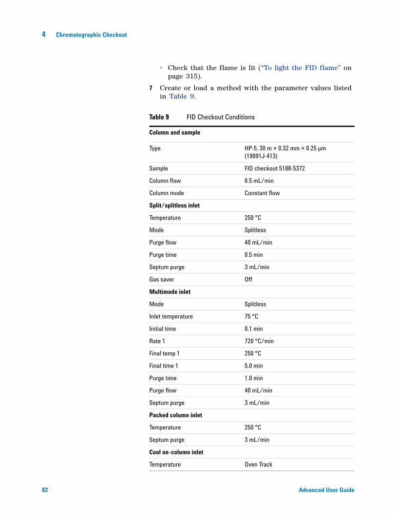
82 Advanced User Guide
4 Chromatographic Checkout
• Check that the flame is lit (“To light the FID flame” on page 315).
7 Create or load a method with the parameter values listed in Table 9.
Table 9 FID Checkout Conditions
Column and sample
Type HP-5, 30 m × 0.32 mm × 0.25 µm (19091J-413)
Sample FID checkout 5188-5372
Column flow 6.5 mL/min
Column mode Constant flow
Split/splitless inlet
Temperature 250 °C
Mode Splitless
Purge flow 40 mL/min
Purge time 0.5 min
Septum purge 3 mL/min
Gas saver Off
Multimode inlet
Mode Splitless
Inlet temperature 75 °C
Initial time 0.1 min
Rate 1 720 °C/min
Final temp 1 250 °C
Final time 1 5.0 min
Purge time 1.0 min
Purge flow 40 mL/min
Septum purge 3 mL/min
Packed column inlet
Temperature 250 °C
Septum purge 3 mL/min
Cool on-column inlet
Temperature Oven Track
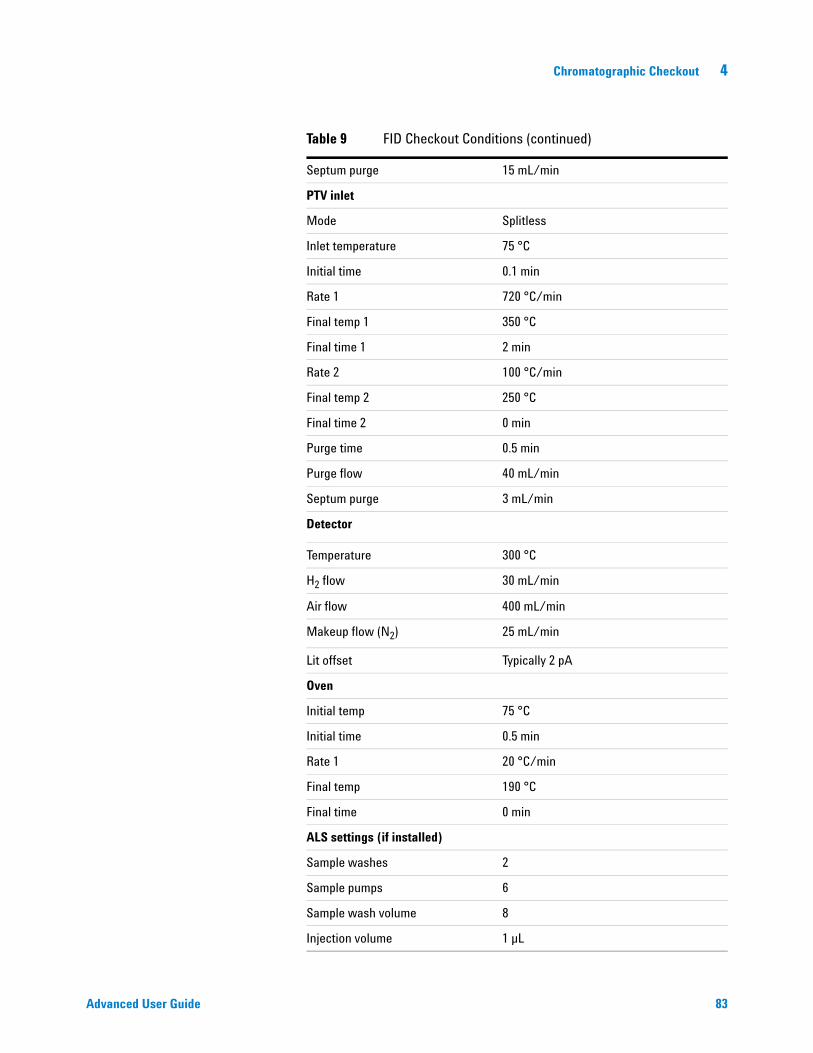
Chromatographic Checkout 4
Advanced User Guide 83
Septum purge 15 mL/min
PTV inlet
Mode Splitless
Inlet temperature 75 °C
Initial time 0.1 min
Rate 1 720 °C/min
Final temp 1 350 °C
Final time 1 2 min
Rate 2 100 °C/min
Final temp 2 250 °C
Final time 2 0 min
Purge time 0.5 min
Purge flow 40 mL/min
Septum purge 3 mL/min
Detector
Temperature 300 °C
H2 flow 30 mL/min
Air flow 400 mL/min
Makeup flow (N2) 25 mL/min
Lit offset Typically 2 pA
Oven
Initial temp 75 °C
Initial time 0.5 min
Rate 1 20 °C/min
Final temp 190 °C
Final time 0 min
ALS settings (if installed)
Sample washes 2
Sample pumps 6
Sample wash volume 8
Injection volume 1 µL
Table 9 FID Checkout Conditions (continued)
84 Advanced User Guide
4 Chromatographic Checkout
8 If using a data system, prepare the data system to perform one run using the loaded checkout method. Make sure that the data system will output a chromatogram.
If not using a data system, create a one sample sequence using the GC keypad.
9 Start the run.
If performing an injection using an autosampler, start the run using the data system or press [Start] on the GC.
If performing a manual injection (with or without a data system):
a Press [Prep Run] to prepare the inlet for splitless injection.
b When the GC becomes ready, inject 1 µL of the checkout sample and press [Start] on the GC.
Syringe size 10 µL
Solvent A pre washes 2
Solvent A post washes 2
Solvent A wash volume 8
Solvent B pre washes 0
Solvent B post washes 0
Solvent B wash volume 0
Injection mode (7693A) Normal
Airgap Volume (7693A) 0.20
Viscosity delay 0
Inject Dispense Speed (7693A) 6000
Plunger speed (7683) Fast, for all inlets except COC.
PreInjection dwell 0
PostInjection dwell 0
Manual injection
Injection volume 1 µL
Data system
Data rate 5 Hz
Table 9 FID Checkout Conditions (continued)
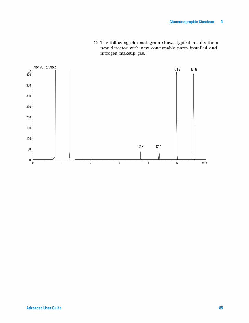
Chromatographic Checkout 4
Advanced User Guide 85
10 The following chromatogram shows typical results for a new detector with new consumable parts installed and nitrogen makeup gas.
min0 1 2 3 4 5
pA
0
50
100
150
200
250
300
350
400
FID1 A, (C:\FID.D)
C13 C14
C15 C16
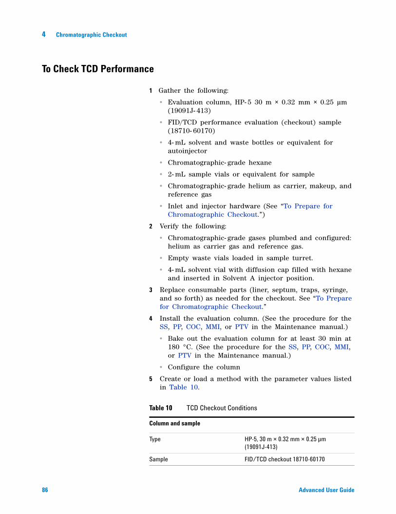
86 Advanced User Guide
4 Chromatographic Checkout
To Check TCD Performance
1 Gather the following:
• Evaluation column, HP- 5 30 m × 0.32 mm × 0.25 µm (19091J- 413)
• FID/TCD performance evaluation (checkout) sample (18710- 60170)
• 4- mL solvent and waste bottles or equivalent for autoinjector
• Chromatographic- grade hexane
• 2- mL sample vials or equivalent for sample
• Chromatographic- grade helium as carrier, makeup, and reference gas
• Inlet and injector hardware (See “To Prepare for Chromatographic Checkout.”)
2 Verify the following:
• Chromatographic- grade gases plumbed and configured: helium as carrier gas and reference gas.
• Empty waste vials loaded in sample turret.
• 4- mL solvent vial with diffusion cap filled with hexane and inserted in Solvent A injector position.
3 Replace consumable parts (liner, septum, traps, syringe, and so forth) as needed for the checkout. See “To Prepare for Chromatographic Checkout.”
4 Install the evaluation column. (See the procedure for the SS, PP, COC, MMI, or PTV in the Maintenance manual.)
• Bake out the evaluation column for at least 30 min at 180 °C. (See the procedure for the SS, PP, COC, MMI, or PTV in the Maintenance manual.)
• Configure the column
5 Create or load a method with the parameter values listed in Table 10.
Table 10 TCD Checkout Conditions
Column and sample
Type HP-5, 30 m × 0.32 mm × 0.25 µm (19091J-413)
Sample FID/TCD checkout 18710-60170
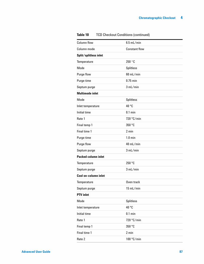
Chromatographic Checkout 4
Advanced User Guide 87
Column flow 6.5 mL/min
Column mode Constant flow
Split/splitless inlet
Temperature 250 °C
Mode Splitless
Purge flow 60 mL/min
Purge time 0.75 min
Septum purge 3 mL/min
Multimode inlet
Mode Splitless
Inlet temperature 40 °C
Initial time 0.1 min
Rate 1 720 °C/min
Final temp 1 350 °C
Final time 1 2 min
Purge time 1.0 min
Purge flow 40 mL/min
Septum purge 3 mL/min
Packed column inlet
Temperature 250 °C
Septum purge 3 mL/min
Cool on-column inlet
Temperature Oven track
Septum purge 15 mL/min
PTV inlet
Mode Splitless
Inlet temperature 40 °C
Initial time 0.1 min
Rate 1 720 °C/min
Final temp 1 350 °C
Final time 1 2 min
Rate 2 100 °C/min
Table 10 TCD Checkout Conditions (continued)
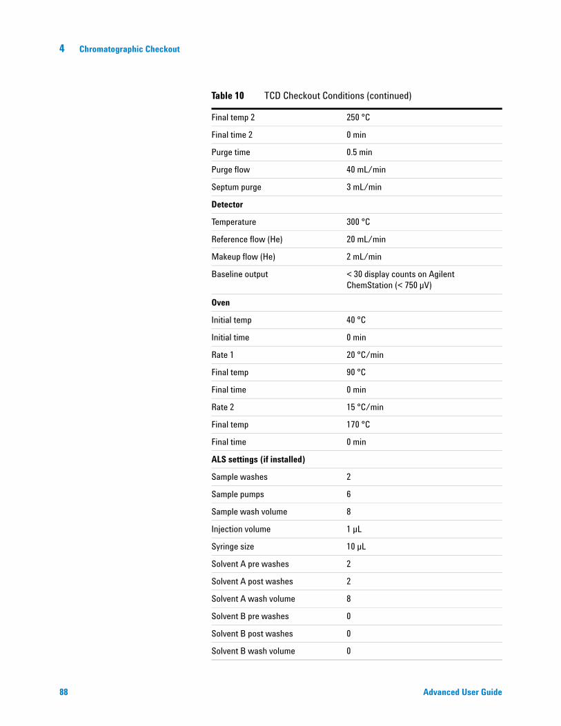
88 Advanced User Guide
4 Chromatographic Checkout
Final temp 2 250 °C
Final time 2 0 min
Purge time 0.5 min
Purge flow 40 mL/min
Septum purge 3 mL/min
Detector
Temperature 300 °C
Reference flow (He) 20 mL/min
Makeup flow (He) 2 mL/min
Baseline output < 30 display counts on Agilent ChemStation (< 750 µV)
Oven
Initial temp 40 °C
Initial time 0 min
Rate 1 20 °C/min
Final temp 90 °C
Final time 0 min
Rate 2 15 °C/min
Final temp 170 °C
Final time 0 min
ALS settings (if installed)
Sample washes 2
Sample pumps 6
Sample wash volume 8
Injection volume 1 µL
Syringe size 10 µL
Solvent A pre washes 2
Solvent A post washes 2
Solvent A wash volume 8
Solvent B pre washes 0
Solvent B post washes 0
Solvent B wash volume 0
Table 10 TCD Checkout Conditions (continued)
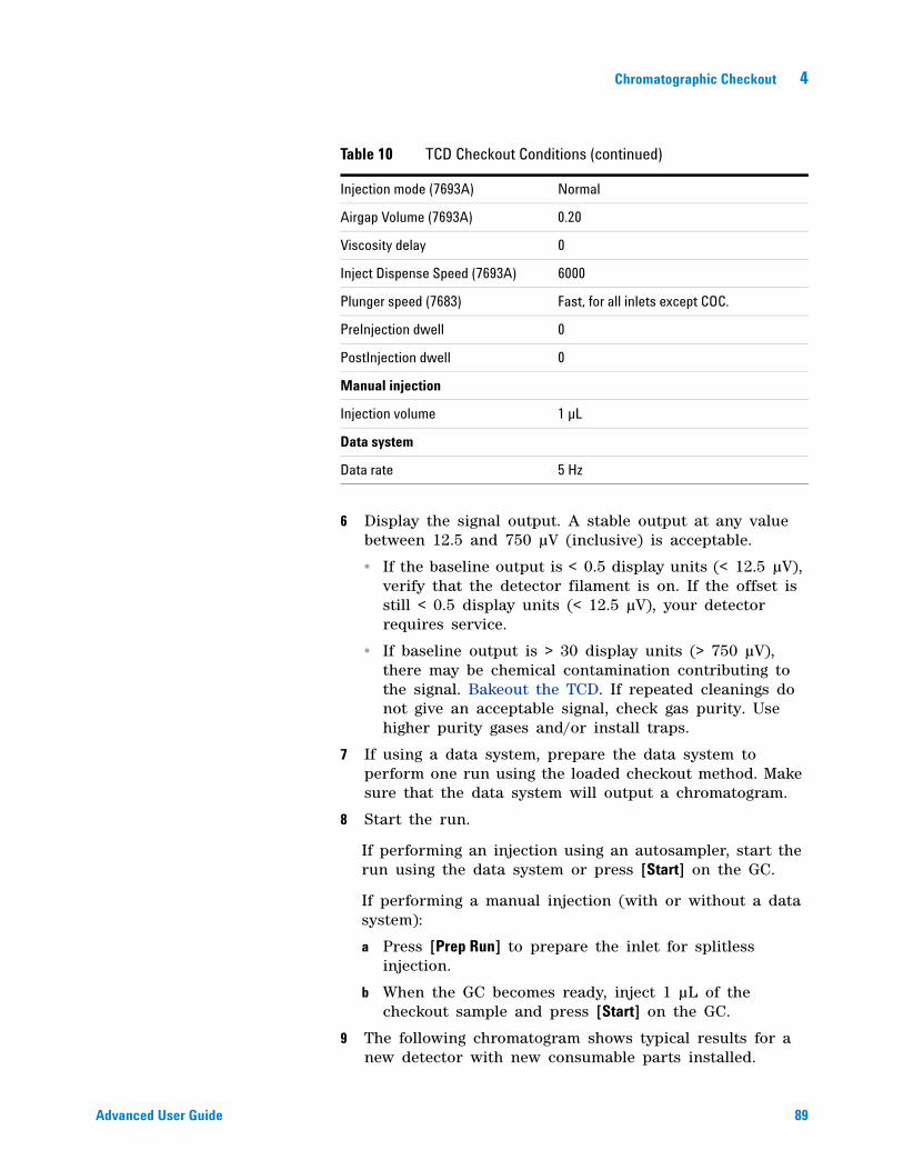
Chromatographic Checkout 4
Advanced User Guide 89
6 Display the signal output. A stable output at any value between 12.5 and 750 µV (inclusive) is acceptable.
• If the baseline output is < 0.5 display units (< 12.5 µV), verify that the detector filament is on. If the offset is still < 0.5 display units (< 12.5 µV), your detector requires service.
• If baseline output is > 30 display units (> 750 µV), there may be chemical contamination contributing to the signal. Bakeout the TCD. If repeated cleanings do not give an acceptable signal, check gas purity. Use higher purity gases and/or install traps.
7 If using a data system, prepare the data system to perform one run using the loaded checkout method. Make sure that the data system will output a chromatogram.
8 Start the run.
If performing an injection using an autosampler, start the run using the data system or press [Start] on the GC.
If performing a manual injection (with or without a data system):
a Press [Prep Run] to prepare the inlet for splitless injection.
b When the GC becomes ready, inject 1 µL of the checkout sample and press [Start] on the GC.
9 The following chromatogram shows typical results for a new detector with new consumable parts installed.
Injection mode (7693A) Normal
Airgap Volume (7693A) 0.20
Viscosity delay 0
Inject Dispense Speed (7693A) 6000
Plunger speed (7683) Fast, for all inlets except COC.
PreInjection dwell 0
PostInjection dwell 0
Manual injection
Injection volume 1 µL
Data system
Data rate 5 Hz
Table 10 TCD Checkout Conditions (continued)
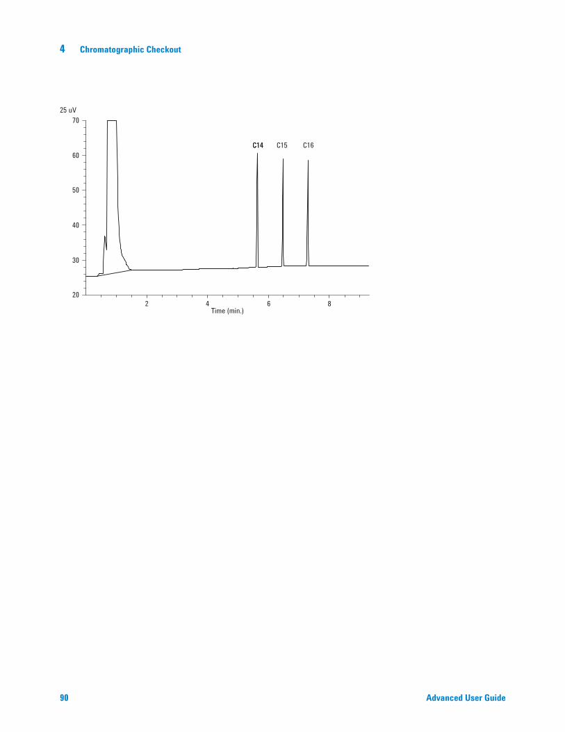
90 Advanced User Guide
4 Chromatographic Checkout
2 4 6 820
30
40
50
60
70
Time (min.)
25 uV
C14 C15 C16C14
Chromatographic Checkout 4
Advanced User Guide 91
To Check NPD Performance
1 Gather the following:
• Evaluation column, HP- 5 30 m × 0.32 mm × 0.25 µm (19091J- 413)
• NPD performance evaluation (checkout) sample (18789- 60060)
• 4- mL solvent and waste bottles or equivalent for autoinjector.
• Chromatographic- grade isooctane
• 2- mL sample vials or equivalent for sample.
• Inlet and injector hardware (See “To Prepare for Chromatographic Checkout.”)
2 Verify the following:
• Capillary column jet installed. If not, select and install a capillary column jet.
• Capillary column adapter installed. If not, install it.
• Chromatographic- grade gases plumbed and configured: helium as carrier gas, nitrogen, hydrogen, and air.
• Empty waste vials loaded in sample turret.
• 4- mL vial with diffusion cap filled with isooctane and inserted in Solvent A injector position.
3 Replace consumable parts (liner, septum, traps, syringe, and so forth) as needed for the checkout. See “To Prepare for Chromatographic Checkout.”
4 If present, remove any protective caps from the inlet manifold vents.
5 Install the evaluation column. (See the procedure for the SS, PP, COC, MMI, or PTV in the Maintenance manual.)
• Bake out the evaluation column for at least 30 min at 180 °C. (See the procedure for the SS, PP, COC, MMI, or PTV in the Maintenance manual.)
• Be sure to configure the column
6 Create or load a method with the parameter values listed in Table 11.
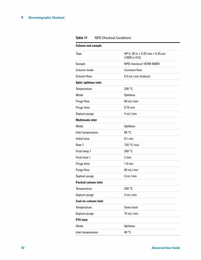
92 Advanced User Guide
4 Chromatographic Checkout
Table 11 NPD Checkout Conditions
Column and sample
Type HP-5, 30 m × 0.32 mm × 0.25 µm (19091J-413)
Sample NPD checkout 18789-60060
Column mode Constant flow
Column flow 6.5 mL/min (helium)
Split/splitless inlet
Temperature 200 °C
Mode Splitless
Purge flow 60 mL/min
Purge time 0.75 min
Septum purge 3 mL/min
Multimode inlet
Mode Splitless
Inlet temperature 60 °C
Initial time 0.1 min
Rate 1 720 °C/min
Final temp 1 350 °C
Final time 1 2 min
Purge time 1.0 min
Purge flow 60 mL/min
Septum purge 3 mL/min
Packed column inlet
Temperature 200 °C
Septum purge 3 mL/min
Cool on-column inlet
Temperature Oven track
Septum purge 15 mL/min
PTV inlet
Mode Splitless
Inlet temperature 60 °C
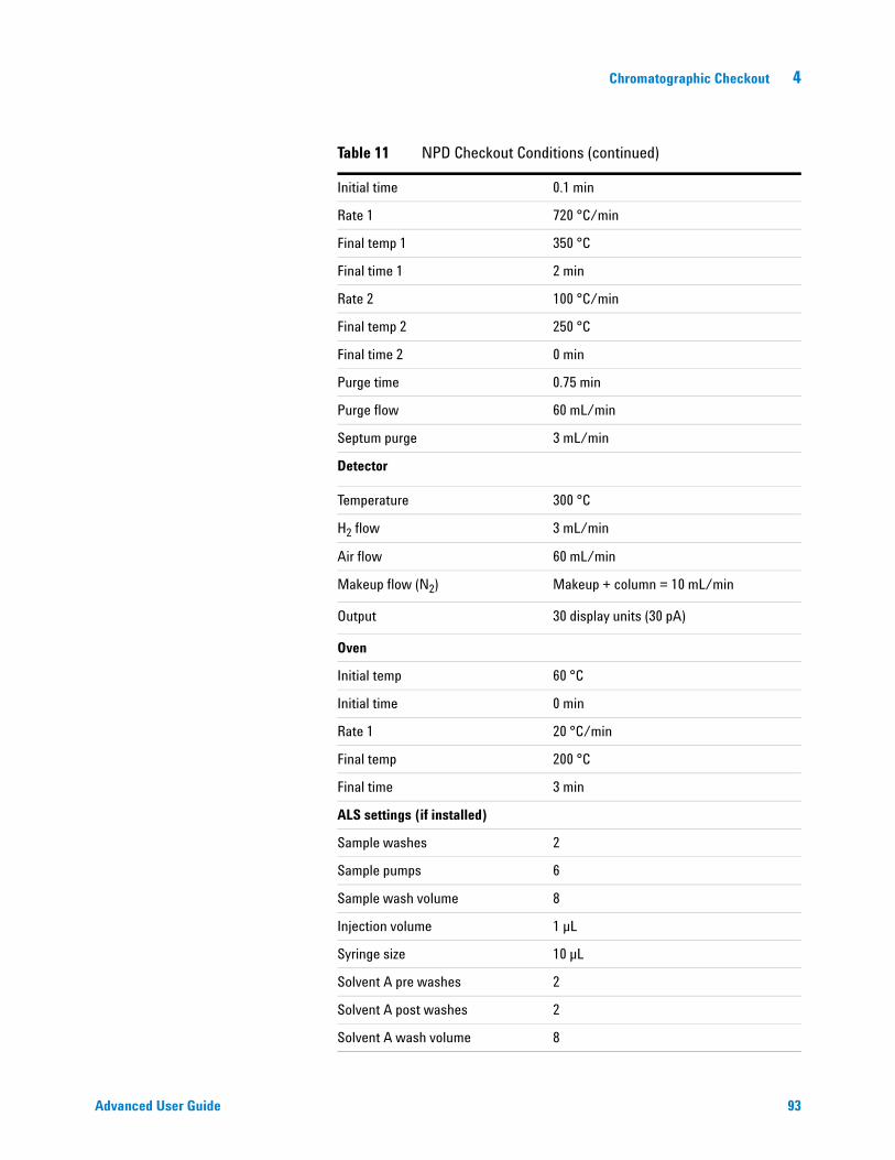
Chromatographic Checkout 4
Advanced User Guide 93
Initial time 0.1 min
Rate 1 720 °C/min
Final temp 1 350 °C
Final time 1 2 min
Rate 2 100 °C/min
Final temp 2 250 °C
Final time 2 0 min
Purge time 0.75 min
Purge flow 60 mL/min
Septum purge 3 mL/min
Detector
Temperature 300 °C
H2 flow 3 mL/min
Air flow 60 mL/min
Makeup flow (N2) Makeup + column = 10 mL/min
Output 30 display units (30 pA)
Oven
Initial temp 60 °C
Initial time 0 min
Rate 1 20 °C/min
Final temp 200 °C
Final time 3 min
ALS settings (if installed)
Sample washes 2
Sample pumps 6
Sample wash volume 8
Injection volume 1 µL
Syringe size 10 µL
Solvent A pre washes 2
Solvent A post washes 2
Solvent A wash volume 8
Table 11 NPD Checkout Conditions (continued)
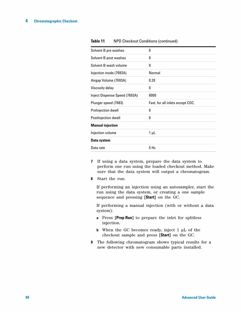
94 Advanced User Guide
4 Chromatographic Checkout
7 If using a data system, prepare the data system to perform one run using the loaded checkout method. Make sure that the data system will output a chromatogram.
8 Start the run.
If performing an injection using an autosampler, start the run using the data system, or creating a one sample sequence and pressing [Start] on the GC.
If performing a manual injection (with or without a data system):
a Press [Prep Run] to prepare the inlet for splitless injection.
b When the GC becomes ready, inject 1 µL of the checkout sample and press [Start] on the GC.
9 The following chromatogram shows typical results for a new detector with new consumable parts installed.
Solvent B pre washes 0
Solvent B post washes 0
Solvent B wash volume 0
Injection mode (7693A) Normal
Airgap Volume (7693A) 0.20
Viscosity delay 0
Inject Dispense Speed (7693A) 6000
Plunger speed (7683) Fast, for all inlets except COC.
PreInjection dwell 0
PostInjection dwell 0
Manual injection
Injection volume 1 µL
Data system
Data rate 5 Hz
Table 11 NPD Checkout Conditions (continued)
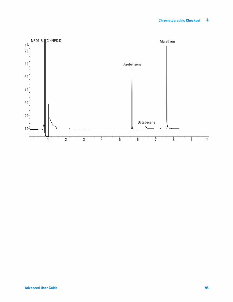
Chromatographic Checkout 4
Advanced User Guide 95
m1 2 3 4 5 6 7 8 9
pA
10
20
30
40
50
60
70
NPD1 B, (C:\NPD.D)
Azobenzene
Malathion
Octadecane
96 Advanced User Guide
4 Chromatographic Checkout
To Check uECD Performance
1 Gather the following:
• Evaluation column, HP- 5 30 m × 0.32 mm × 0.25 µm (19091J- 413)
• uECD performance evaluation (checkout) sample (18713–60040, Japan: 5183- 0379)
• 4- mL solvent and waste bottles or equivalent for autoinjector.
• Chromatographic- grade isooctane
• 2- mL sample vials or equivalent for sample.
• Inlet and injector hardware (See “To Prepare for Chromatographic Checkout.”)
2 Verify the following:
• Clean fused silica indented mixing liner installed. If not, install it.
• Chromatographic- grade gases plumbed and configured: helium for carrier gas, nitrogen for makeup.
• Empty waste vials loaded in sample turret.
• 4- mL vial with diffusion cap filled with hexane and inserted in Solvent A injector position.
3 Replace consumable parts (liner, septum, traps, syringe, and so forth) as needed for the checkout. See “To Prepare for Chromatographic Checkout.”
4 Install the evaluation column. (See the procedure for the SS, PP, COC, MMI, or PTV in the Maintenance manual.)
• Bake out the evaluation column for at least 30 minutes at 180 °C. (See the procedure for the SS, PP, COC, MMI, or PTV in the Maintenance manual.)
• Be sure to configure the column.
5 Display the signal output to determine baseline output. A stable baseline output at any value between 0.5 and 1000 Hz (ChemStation display units) (inclusive) is acceptable.
• If the baseline output is < 0.5 Hz, verify that the electrometer is on. If the offset is still < 0.5 Hz, your detector requires service.
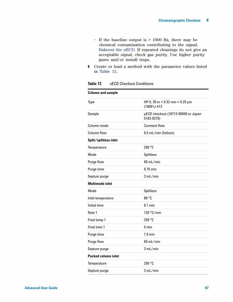
Chromatographic Checkout 4
Advanced User Guide 97
• If the baseline output is > 1000 Hz, there may be chemical contamination contributing to the signal. Bakeout the uECD. If repeated cleanings do not give an acceptable signal, check gas purity. Use higher purity gases and/or install traps.
6 Create or load a method with the parameter values listed in Table 12.
Table 12 uECD Checkout Conditions
Column and sample
Type HP-5, 30 m × 0.32 mm × 0.25 µm (19091J-413
Sample µECD checkout (18713-60040 or Japan: 5183-0379)
Column mode Constant flow
Column flow 6.5 mL/min (helium)
Split/splitless inlet
Temperature 200 °C
Mode Splitless
Purge flow 60 mL/min
Purge time 0.75 min
Septum purge 3 mL/min
Multimode inlet
Mode Splitless
Inlet temperature 80 °C
Initial time 0.1 min
Rate 1 720 °C/min
Final temp 1 250 °C
Final time 1 5 min
Purge time 1.0 min
Purge flow 60 mL/min
Septum purge 3 mL/min
Packed column inlet
Temperature 200 °C
Septum purge 3 mL/min
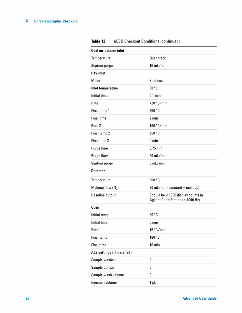
98 Advanced User Guide
4 Chromatographic Checkout
Cool on-column inlet
Temperature Oven track
Septum purge 15 mL/min
PTV inlet
Mode Splitless
Inlet temperature 80 °C
Initial time 0.1 min
Rate 1 720 °C/min
Final temp 1 350 °C
Final time 1 2 min
Rate 2 100 °C/min
Final temp 2 250 °C
Final time 2 0 min
Purge time 0.75 min
Purge flow 60 mL/min
Septum purge 3 mL/min
Detector
Temperature 300 °C
Makeup flow (N2) 30 mL/min (constant + makeup)
Baseline output Should be < 1000 display counts in Agilent ChemStation (< 1000 Hz)
Oven
Initial temp 80 °C
Initial time 0 min
Rate 1 15 °C/min
Final temp 180 °C
Final time 10 min
ALS settings (if installed)
Sample washes 2
Sample pumps 6
Sample wash volume 8
Injection volume 1 µL
Table 12 uECD Checkout Conditions (continued)
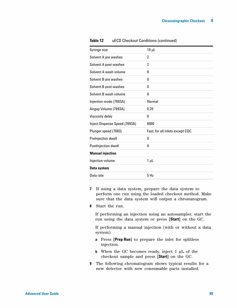
Chromatographic Checkout 4
Advanced User Guide 99
7 If using a data system, prepare the data system to perform one run using the loaded checkout method. Make sure that the data system will output a chromatogram.
8 Start the run.
If performing an injection using an autosampler, start the run using the data system or press [Start] on the GC.
If performing a manual injection (with or without a data system):
a Press [Prep Run] to prepare the inlet for splitless injection.
b When the GC becomes ready, inject 1 µL of the checkout sample and press [Start] on the GC.
9 The following chromatogram shows typical results for a new detector with new consumable parts installed.
Syringe size 10 µL
Solvent A pre washes 2
Solvent A post washes 2
Solvent A wash volume 8
Solvent B pre washes 0
Solvent B post washes 0
Solvent B wash volume 0
Injection mode (7693A) Normal
Airgap Volume (7693A) 0.20
Viscosity delay 0
Inject Dispense Speed (7693A) 6000
Plunger speed (7683) Fast, for all inlets except COC.
PreInjection dwell 0
PostInjection dwell 0
Manual injection
Injection volume 1 µL
Data system
Data rate 5 Hz
Table 12 uECD Checkout Conditions (continued)
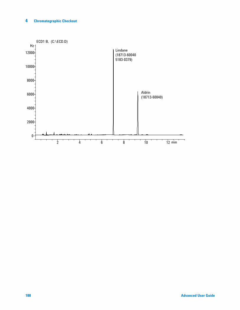
100 Advanced User Guide
4 Chromatographic Checkout
min2 4 6 8 10 12
Hz
0
2000
4000
6000
8000
10000
12000
ECD1 B, (C:\ECD.D)
Lindane(18713-600405183-0379)
Aldrin(18713-60040)
Chromatographic Checkout 4
Advanced User Guide 101
To Check FPD Performance (Sample 5188-5953)
To check FPD performance, first check the phosphorus performance, then the sulfur performance.
Preparation
1 Gather the following:
• Evaluation column, HP- 5 30 m × 0.32 mm × 0.25 µm (19091J- 413)
• FPD performance evaluation (checkout) sample (5188- 5953), 2.5 mg/L (± 0.5%) methylparathion in isooctane
• Phosphorus filter
• Sulfur filter and filter spacer
• 4- mL solvent and waste bottles or equivalent for autoinjector.
• 2- mL sample vials or equivalent for sample.
• Chromatographic- grade isooctane for syringe wash solvent.
• Inlet and injector hardware (See “To Prepare for Chromatographic Checkout.”)
2 Verify the following:
• Capillary column adapter installed. If not, install it.
• Chromatographic- grade gases plumbed and configured: helium as carrier gas, nitrogen, hydrogen, and air.
• Empty waste vials loaded in sample turret.
• 4- mL vial with diffusion cap filled with isooctane and inserted in Solvent A injector position.
3 Replace consumable parts (liner, septum, traps, syringe, and so forth) as needed for the checkout. See “To Prepare for Chromatographic Checkout.”
4 Verify that the Lit Offset is set appropriately. Typically, it should be about 2.0 pA for the checkout method.
5 Install the evaluation column. (See the procedure for the SS, PP, COC, MMI, or PTV in the Maintenance manual.)
• Set the oven, inlet, and detector to 250 °C and bake out for at least 15 minutes.(See the procedure for the SS, PP, COC, MMI, or PTV in the Maintenance manual.)
• Be sure to configure the column.
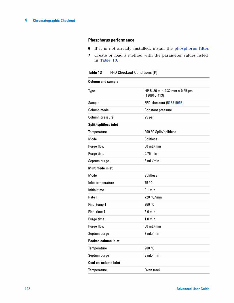
102 Advanced User Guide
4 Chromatographic Checkout
Phosphorus performance
6 If it is not already installed, install the phosphorus filter.
7 Create or load a method with the parameter values listed in Table 13.
Table 13 FPD Checkout Conditions (P)
Column and sample
Type HP-5, 30 m × 0.32 mm × 0.25 µm (19091J-413)
Sample FPD checkout (5188-5953)
Column mode Constant pressure
Column pressure 25 psi
Split/splitless inlet
Temperature 200 °C Split/splitless
Mode Splitless
Purge flow 60 mL/min
Purge time 0.75 min
Septum purge 3 mL/min
Multimode inlet
Mode Splitless
Inlet temperature 75 °C
Initial time 0.1 min
Rate 1 720 °C/min
Final temp 1 250 °C
Final time 1 5.0 min
Purge time 1.0 min
Purge flow 60 mL/min
Septum purge 3 mL/min
Packed column inlet
Temperature 200 °C
Septum purge 3 mL/min
Cool on-column inlet
Temperature Oven track
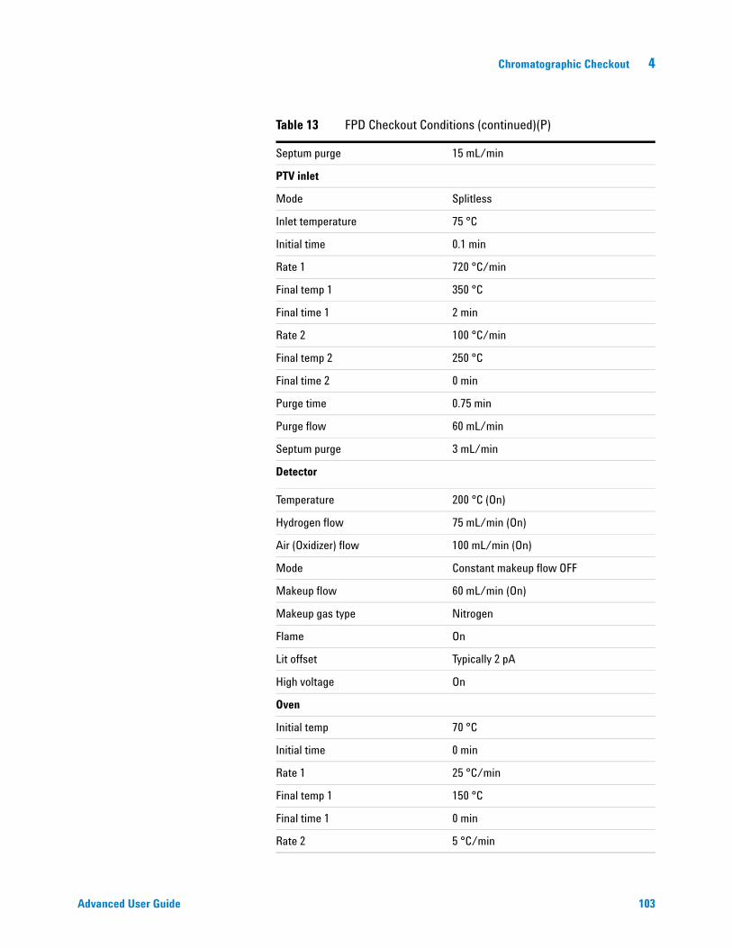
Chromatographic Checkout 4
Advanced User Guide 103
Septum purge 15 mL/min
PTV inlet
Mode Splitless
Inlet temperature 75 °C
Initial time 0.1 min
Rate 1 720 °C/min
Final temp 1 350 °C
Final time 1 2 min
Rate 2 100 °C/min
Final temp 2 250 °C
Final time 2 0 min
Purge time 0.75 min
Purge flow 60 mL/min
Septum purge 3 mL/min
Detector
Temperature 200 °C (On)
Hydrogen flow 75 mL/min (On)
Air (Oxidizer) flow 100 mL/min (On)
Mode Constant makeup flow OFF
Makeup flow 60 mL/min (On)
Makeup gas type Nitrogen
Flame On
Lit offset Typically 2 pA
High voltage On
Oven
Initial temp 70 °C
Initial time 0 min
Rate 1 25 °C/min
Final temp 1 150 °C
Final time 1 0 min
Rate 2 5 °C/min
Table 13 FPD Checkout Conditions (continued)(P)
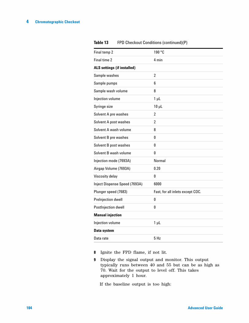
104 Advanced User Guide
4 Chromatographic Checkout
8 Ignite the FPD flame, if not lit.
9 Display the signal output and monitor. This output typically runs between 40 and 55 but can be as high as 70. Wait for the output to level off. This takes approximately 1 hour.
If the baseline output is too high:
Final temp 2 190 °C
Final time 2 4 min
ALS settings (if installed)
Sample washes 2
Sample pumps 6
Sample wash volume 8
Injection volume 1 µL
Syringe size 10 µL
Solvent A pre washes 2
Solvent A post washes 2
Solvent A wash volume 8
Solvent B pre washes 0
Solvent B post washes 0
Solvent B wash volume 0
Injection mode (7693A) Normal
Airgap Volume (7693A) 0.20
Viscosity delay 0
Inject Dispense Speed (7693A) 6000
Plunger speed (7683) Fast, for all inlets except COC.
PreInjection dwell 0
PostInjection dwell 0
Manual injection
Injection volume 1 µL
Data system
Data rate 5 Hz
Table 13 FPD Checkout Conditions (continued)(P)
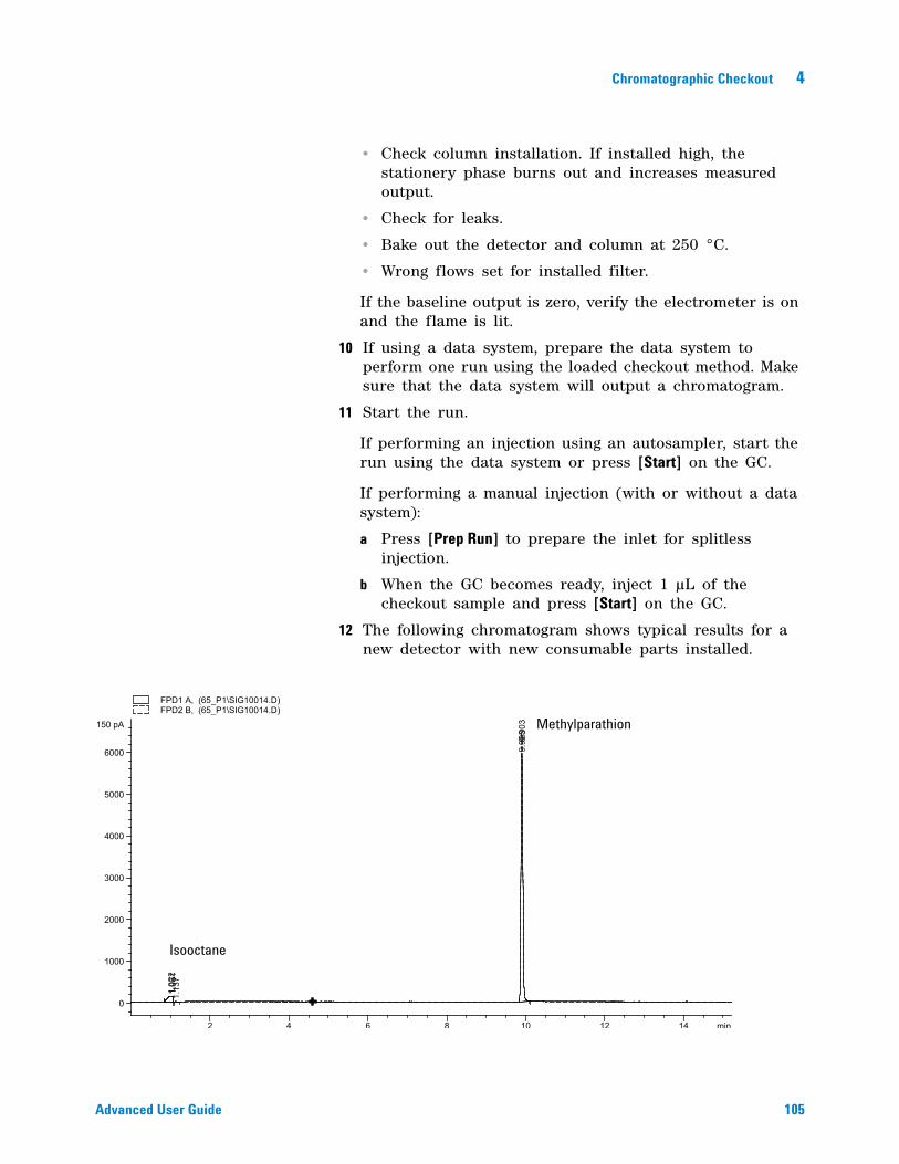
Chromatographic Checkout 4
Advanced User Guide 105
• Check column installation. If installed high, the stationery phase burns out and increases measured output.
• Check for leaks.
• Bake out the detector and column at 250 °C.
• Wrong flows set for installed filter.
If the baseline output is zero, verify the electrometer is on and the flame is lit.
10 If using a data system, prepare the data system to perform one run using the loaded checkout method. Make sure that the data system will output a chromatogram.
11 Start the run.
If performing an injection using an autosampler, start the run using the data system or press [Start] on the GC.
If performing a manual injection (with or without a data system):
a Press [Prep Run] to prepare the inlet for splitless injection.
b When the GC becomes ready, inject 1 µL of the checkout sample and press [Start] on the GC.
12 The following chromatogram shows typical results for a new detector with new consumable parts installed.
Methylparathion
Isooctane
106 Advanced User Guide
4 Chromatographic Checkout
Sulfur performance
13 Install the sulfur filter and filter spacer.
14 Make the following method parameter changes.
15 Ignite the FPD flame if not lit.
16 Display the signal output and monitor. This output typically runs between 50 and 60 but can be as high as 70. Wait for the output to level off. This takes approximately 1 hour.
If the baseline output is too high:
• Check column installation. If installed high, the stationery phase burns out and increases measured output.
• Check for leaks.
• Bake out the detector and column at 250 °C.
• Wrong flows set for installed filter.
If the baseline output is zero, verify the electrometer is on and the flame is lit.
17 If using a data system, prepare the data system to perform one run using the loaded checkout method. Make sure that the data system will output a chromatogram.
18 Start the run.
If performing an injection using an autosampler, start the run using the data system or press [Start] on the GC.
If performing a manual injection (with or without a data system):
a Press [Prep Run] to prepare the inlet for splitless injection.
b When the GC becomes ready, inject 1 µL of the checkout sample and press [Start] on the GC.
19 The following chromatogram shows typical results for a new detector with new consumable parts installed.
Table 14 Sulfur method parameters (S)
Parameter Value ( mL/min)
H2 flow 50
Air flow 60
Chromatographic Checkout 4
Advanced User Guide 107
Methylparathion
Isooctane
108 Advanced User Guide
4 Chromatographic Checkout
To Verify FPD Performance (Sample 5188-5245, Japan)
To verify FPD performance, first check the phosphorus performance, then the sulfur performance.
Preparation
1 Gather the following:
• Evaluation column, DB5 15 m × 0.32 mm × 1.0 µm (123- 5513)
• FPD performance evaluation (checkout) sample (5188- 5245, Japan), composition: n- Dodecane 7499 mg/L (± 5%), Dodecanethiol 2.0 mg/L (± 5%), Tributyl Phosphate 2.0 mg/L (± 5%), tert- Butyldisulfide 1.0 mg/L (± 5%), in isooctane as solvent
• Phosphorus filter
• Sulfur filter and filter spacer
• 4- mL solvent and waste bottles or equivalent for autoinjector.
• 2- mL sample vials or equivalent for sample.
• Chromatographic- grade isooctane for syringe wash solvent.
• Inlet and injector hardware (See “To Prepare for Chromatographic Checkout.”)
2 Verify the following:
• Capillary column adapter installed. If not, install it.
• Chromatographic- grade gases plumbed and configured: helium as carrier gas, nitrogen, hydrogen, and air.
• Empty waste vials loaded in sample turret.
• 4- mL vial with diffusion cap filled with isooctane and inserted in Solvent A injector position.
3 Replace consumable parts (liner, septum, traps, syringe, and so forth) as needed for the checkout. See “To Prepare for Chromatographic Checkout.”
4 Verify the lit offset is set appropriately. Typically, it should be about 2.0 pA for the checkout method.
5 Install the evaluation column. (See the procedure for the SS, PP, COC, MMI, or PTV in the Maintenance manual.)
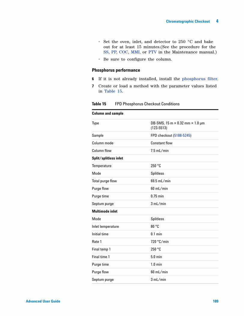
Chromatographic Checkout 4
Advanced User Guide 109
• Set the oven, inlet, and detector to 250 °C and bake out for at least 15 minutes.(See the procedure for the SS, PP, COC, MMI, or PTV in the Maintenance manual.)
• Be sure to configure the column.
Phosphorus performance
6 If it is not already installed, install the phosphorus filter.
7 Create or load a method with the parameter values listed in Table 15.
Table 15 FPD Phosphorus Checkout Conditions
Column and sample
Type DB-5MS, 15 m × 0.32 mm × 1.0 µm (123-5513)
Sample FPD checkout (5188-5245)
Column mode Constant flow
Column flow 7.5 mL/min
Split/splitless inlet
Temperature 250 °C
Mode Splitless
Total purge flow 69.5 mL/min
Purge flow 60 mL/min
Purge time 0.75 min
Septum purge 3 mL/min
Multimode inlet
Mode Splitless
Inlet temperature 80 °C
Initial time 0.1 min
Rate 1 720 °C/min
Final temp 1 250 °C
Final time 1 5.0 min
Purge time 1.0 min
Purge flow 60 mL/min
Septum purge 3 mL/min
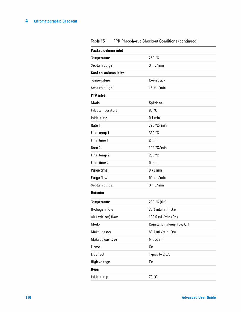
110 Advanced User Guide
4 Chromatographic Checkout
Packed column inlet
Temperature 250 °C
Septum purge 3 mL/min
Cool on-column inlet
Temperature Oven track
Septum purge 15 mL/min
PTV inlet
Mode Splitless
Inlet temperature 80 °C
Initial time 0.1 min
Rate 1 720 °C/min
Final temp 1 350 °C
Final time 1 2 min
Rate 2 100 °C/min
Final temp 2 250 °C
Final time 2 0 min
Purge time 0.75 min
Purge flow 60 mL/min
Septum purge 3 mL/min
Detector
Temperature 200 °C (On)
Hydrogen flow 75.0 mL/min (On)
Air (oxidizer) flow 100.0 mL/min (On)
Mode Constant makeup flow Off
Makeup flow 60.0 mL/min (On)
Makeup gas type Nitrogen
Flame On
Lit offset Typically 2 pA
High voltage On
Oven
Initial temp 70 °C
Table 15 FPD Phosphorus Checkout Conditions (continued)
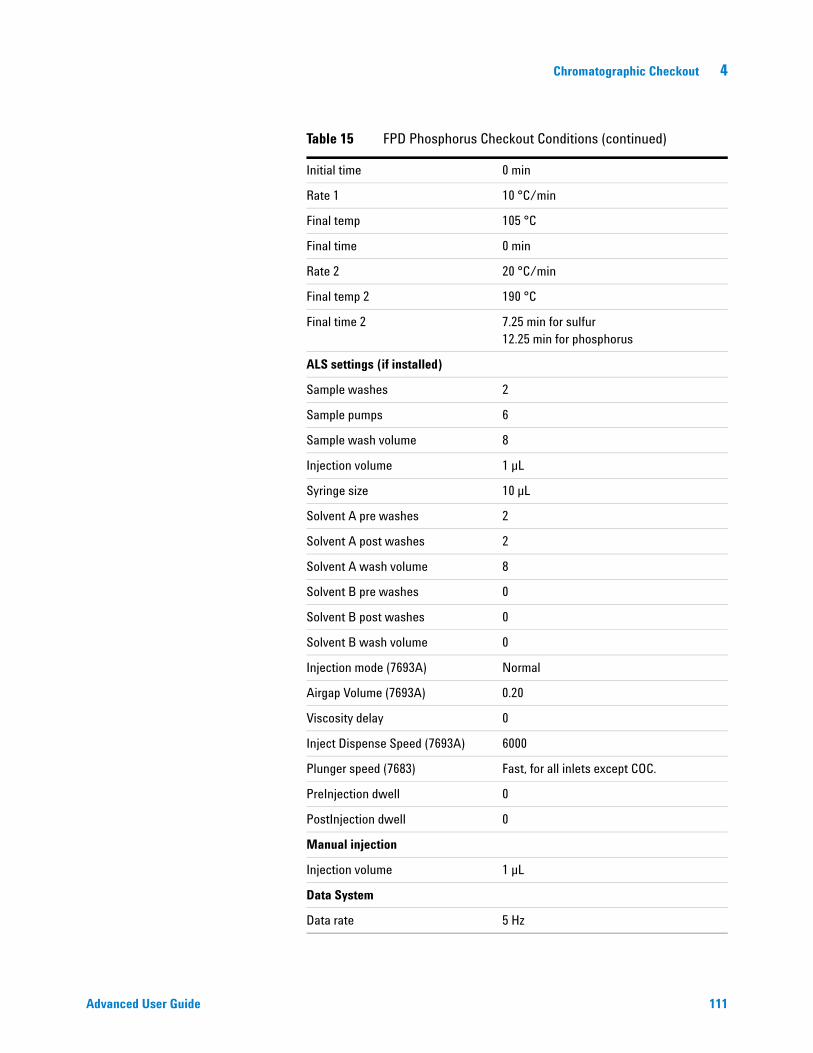
Chromatographic Checkout 4
Advanced User Guide 111
Initial time 0 min
Rate 1 10 °C/min
Final temp 105 °C
Final time 0 min
Rate 2 20 °C/min
Final temp 2 190 °C
Final time 2 7.25 min for sulfur12.25 min for phosphorus
ALS settings (if installed)
Sample washes 2
Sample pumps 6
Sample wash volume 8
Injection volume 1 µL
Syringe size 10 µL
Solvent A pre washes 2
Solvent A post washes 2
Solvent A wash volume 8
Solvent B pre washes 0
Solvent B post washes 0
Solvent B wash volume 0
Injection mode (7693A) Normal
Airgap Volume (7693A) 0.20
Viscosity delay 0
Inject Dispense Speed (7693A) 6000
Plunger speed (7683) Fast, for all inlets except COC.
PreInjection dwell 0
PostInjection dwell 0
Manual injection
Injection volume 1 µL
Data System
Data rate 5 Hz
Table 15 FPD Phosphorus Checkout Conditions (continued)
112 Advanced User Guide
4 Chromatographic Checkout
8 Ignite the FPD flame, if not lit.
9 Display the signal output and monitor. This output typically runs between 40 and 55 but can be as high as 70. Wait for the output to level off. This takes approximately 1 hour.
If the baseline output is too high:
• Check column installation. If installed high, the stationery phase burns out and increases measured output.
• Check for leaks.
• Bake out the detector and column at 250 °C.
• Wrong flows set for installed filter
If the baseline output is zero, verify the electrometer is on and the flame is lit.
10 If using a data system, prepare the data system to perform one run using the loaded checkout method. Make sure that the data system will output a chromatogram.
11 Start the run.
If performing an injection using an autosampler, start the run using the data system or press [Start] on the GC.
If performing a manual injection (with or without a data system):
a Press [Prep Run] to prepare the inlet for splitless injection.
b When the GC becomes ready, inject 1 µL of the checkout sample and press [Start] on the GC.
12 The following chromatogram shows typical results for a new detector with new consumable parts installed.

Chromatographic Checkout 4
Advanced User Guide 113
Sulfur performance
13 Install the sulfur filter.
14 Make the following method parameter changes.
15 Ignite the FPD flame, if not lit.
16 Display the signal output and monitor. This output typically runs between 50 and 60 but can be as high as 70. Wait for the output to level off. This takes approximately 2 hours.
If the baseline output is too high:
• Check column installation. If installed high, the stationery phase burns out and increases measured output.
• Check for leaks.
• Bake out the detector and column at 250 °C.
• Wrong flows set for installed filter
Tributylphosphate
Isooctane t-Butyldisulfide
Table 16 Sulfur method parameters
Parameter Value ( mL/min)
H2 flow 50
Air flow 60
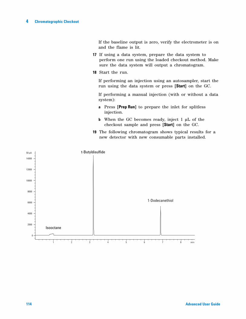
114 Advanced User Guide
4 Chromatographic Checkout
If the baseline output is zero, verify the electrometer is on and the flame is lit.
17 If using a data system, prepare the data system to perform one run using the loaded checkout method. Make sure the data system will output a chromatogram.
18 Start the run.
If performing an injection using an autosampler, start the run using the data system or press [Start] on the GC.
If performing a manual injection (with or without a data system):
a Press [Prep Run] to prepare the inlet for splitless injection.
b When the GC becomes ready, inject 1 µL of the checkout sample and press [Start] on the GC.
19 The following chromatogram shows typical results for a new detector with new consumable parts installed.
t-Butyldisulfide
1-Dodecanethiol
Isooctane
115
Agilent 7890A Gas ChromatographAdvanced User Guide
Agilent Technologies
5Methods and Sequences
Creating Methods 116
To program a method 117
To program the ALS 117
To program the ALS sampler tray 117
To program the 7683B ALS bar code reader 118
To save a method 119
To load a stored method 119
Method mismatch 120
Creating Sequences 121
About the priority sequence 121
To program a sequence 122
To program a priority sequence 122
To program an ALS subsequence 123
To program a valve subsequence 123
To program post sequence events 123
To save a sequence 124
To load a stored sequence 124
To determine sequence status 124
To start a sequence 124
To pause and resume a sequence 125
To stop a sequence 125
To abort a sequence 125
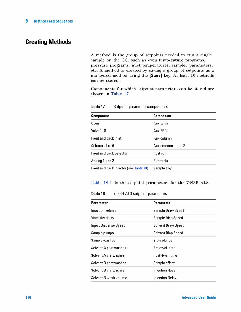
116 Advanced User Guide
5 Methods and Sequences
Creating Methods
A method is the group of setpoints needed to run a single sample on the GC, such as oven temperature programs, pressure programs, inlet temperatures, sampler parameters, etc. A method is created by saving a group of setpoints as a numbered method using the [Store] key. At least 10 methods can be stored.
Components for which setpoint parameters can be stored are shown in Table 17.
Table 18 lists the setpoint parameters for the 7683B ALS.
Table 17 Setpoint parameter components
Component Component
Oven Aux temp
Valve 1–8 Aux EPC
Front and back inlet Aux column
Columns 1 to 6 Aux detector 1 and 2
Front and back detector Post run
Analog 1 and 2 Run table
Front and back injector (see Table 18) Sample tray
Table 18 7683B ALS setpoint parameters
Parameter Parameter
Injection volume Sample Draw Speed
Viscosity delay Sample Disp Speed
Inject Dispense Speed Solvent Draw Speed
Sample pumps Solvent Disp Speed
Sample washes Slow plunger
Solvent A post washes Pre dwell time
Solvent A pre washes Post dwell time
Solvent B post washes Sample offset
Solvent B pre washes Injection Reps
Solvent B wash volume Injection Delay
Methods and Sequences 5
Advanced User Guide 117
The GC also saves ALS setpoints. See the 7693A Installation, Operation, and Maintenance manual for details on its setpoints.
Setpoint parameters are saved when the GC is turned off and loaded when you turn the instrument back on. However, if the hardware was changed while the instrument was turned off, it may not be possible to restore all setpoints in the method.
To program a method
1 Individually select each component for which setpoint parameters are appropriate for your method. (See Table 17.)
2 Examine the current setpoints and modify as desired. Repeat for each component as appropriate.
3 Examine the current setpoints for the ALS, if appropriate, and modify as desired. (See “To program the ALS” on page 117.)
4 Save the setpoints as a stored method. (See “To save a method” on page 119.)
To program the ALS
1 Press [Front Injector] or [Back Injector].
2 Scroll to the desired setpoint. (See Table 18.)
3 Enter a setpoint value.
4 Examine the current setpoints for the sampler tray, if appropriate, and modify as desired. (See “To program the ALS sampler tray” on page 117.)
5 Examine the current setpoints for the bar code reader, if appropriate, and modify as desired. (See “To program the 7683B ALS bar code reader” on page 118.)
6 Save the setpoints as a stored method. (See “To save a method” on page 119.)
To program the ALS sampler tray
For the 7693A sampler tray, see the 7693A Installation, Operation, and Maintenance manual.
118 Advanced User Guide
5 Methods and Sequences
For the 7683B sampler tray:
1 Press [Sample tray].
2 Press [On/Yes] to enable the barcode reader (if present) or [Off/No] to disable it.
Configuration issues
1 To edit the sample tray configuration setpoints, press [Config][Sample Tray].
Normally, no tray configuration is required. If using a bar code reader and the tray gripper arm has difficulties retrieving a vial from the bar code reader, adjust the gripper offset (step 2). If the sample vial contacts the side of the turret hole when the tray delivers or retrieves the sample vial, then adjust the injector offset (step 3).
2 Scroll to Grip offset and press [Mode/Type]. Select from:
• Up to raise the gripper arm pickup height
• Default
• Down to lower the gripper arm pickup height
and press [Enter].
3 Scroll to Front Injector Offset or Back Injector Offset and press [Mode/Type]. Select from:
• Clockwise to have the gripper arm meet the turret at a further clockwise position (relative to turret rotation)
• Default
• CounterClockwise to have the gripper arm meet the turret at a further counterclockwise position (relative to turret rotation)
and press [Enter].
To program the 7683B ALS bar code reader
For the 7693A sampler bar code reader, see the 7693A Installation, Operation, and Maintenance manual.
1 Press [Sample tray].
2 Scroll to Enable bar code reader and press [On/Yes] to enable or [Off/No] to disable the bar code reader.
Methods and Sequences 5
Advanced User Guide 119
Configuration issues
1 To edit the bar code configuration setpoints, press [Config][Sample Tray].
2 Select Bar Code Reader.
3 Press [On/Yes] or [Off/No] to control the following bar code setpoints:
• Enable 3 of 9—encodes both letters and numbers, plus a few punctuation marks, and message length can be varied to suit both the amount of data to be encoded and the space available
• Enable 2 of 5—restricted to numbers but does allow variable message length
• Enable UPC code—restricted to numbers- only with fixed message length
• Enable checksum—verifies that the checksum in the message matches the checksum calculated from the message characters, but does not include the checksum character in the returned message
4 Enter 3 as the BCR Position when the reader is installed in the front of the tray. Positions 1–19 are available.
To save a method
1 Press [Method] and scroll to the desired method number.
2 Press [Store] and [On/Yes] to store the new method using the chosen number. Alternatively, press [Off/No] to return to the stored methods list without saving the method.
A message is displayed if a method with the number you selected already exists.
• Press [On/Yes] to replace the existing method or [Off/No] to return to the stored methods list without saving the method.
To load a stored method
Press [Load][Method]. Supply the method number and press [Enter]. The specified method will replace the current active method.
120 Advanced User Guide
5 Methods and Sequences
Method mismatch
This section applies only to a standalone (not connected to a data system) GC. When a data system, such as a ChemStation or EZChrom Elite, controls the GC, methods are stored in the data system and can be edited there. See your data system documentation for more information.
Suppose your standalone GC is equipped with a single FID. You have created and saved methods that use this detector. Now you remove the FID and install a TCD in its place. When you try to load one of your stored methods, you observe an error message saying that the method and the hardware do not match.
The problem is that the actual hardware is no longer the same as the hardware configuration saved in the method. The method cannot run because it does not know how to operate the recently- added TCD.
On inspecting the method, you find that the detector- related parameters have all been reset to the default values.
Correcting a method mismatch on a standalone GC
This problem can be avoided if you follow this procedure for any hardware change, even including the simple replacement of a defective detector board.
1 Before changing any hardware, press [Config][hardware module], where [hardware module] is the device you intend to replace.
2 Press [Mode/Type]. Select Remove module and press [Enter]. The module is now Unconfigured.
3 Turn the GC off.
4 Make the hardware change that you intended (in this example, remove the FID and its flow module and replace them with the TCD and its module).
5 Turn the GC on. Press [Config][hardware module].
6 Press [Mode/Type]. Select Install module and press [Enter]. The GC will install the new hardware module, which corrects the active method (but not the stored one!).
7 Save the corrected method using the same number (which overwrites the stored method) or a new number (which saves both versions of the method).
Methods and Sequences 5
Advanced User Guide 121
Creating Sequences
A sequence specifies the samples to be run and the stored method to be used for each. The sequence is divided into a priority sequence (ALS only), subsequences (each of which uses a single method), and post- sequence events
• Priority sequence—allows you to interrupt a running ALS or valve sequence to analyze urgent samples. (See “About the priority sequence” on page 121.)
• Subsequences—contain the stored method number and information that defines a set of samples and calibrators to be analyzed using a particular method. Sampler and/or valve subsequences can be used in the same sequence.
• Post sequence—names a method to be loaded and run after the last run in the last subsequence. Specifies whether the sequence is to be repeated indefinitely or halted after the last subsequence.
Samples in each subsequence are specified as either ALS tray locations or sampling valve positions (gas or liquid sampling valves, often with a stream selection valve).
Five sequences with up to five subsequences each can be stored.
About the priority sequence
The priority sequence consists of a single sampler or valve subsequence and a special Use priority parameter, which can be activated at any time, even when a sequence is running. This feature allows you to interrupt a running sequence without having to edit it.
If Use priority is On, then:
1 The GC and ALS complete the current run, then the sequence pauses.
2 The GC runs the priority sequence.
3 The GC resets the Use priority parameter to Off.
4 The main sequence resumes where it paused.
122 Advanced User Guide
5 Methods and Sequences
To program a sequence
1 Press [Seq]. (Press again, if necessary, to display subsequence information.)
2 Create a priority sequence, if desired. (See “To program a priority sequence” on page 122.) If you might want to use a priority sequence, you must program it now. (Once the sequence starts, you cannot edit it without stopping it.)
3 Scroll to the Method # line of Subseq 1 and enter a method number. Use 0 for the currently active method, 1 to 9 for the stored methods, or [Off/No] to end the sequence.
4 Press [Mode/Type] to select a valve or injector type. (See “To program a valve subsequence” on page 123 or “To program an ALS subsequence” on page 123.)
5 Create the next subsequence or scroll to Post Sequence. (See “To program post sequence events” on page 123.)
6 Save the completed sequence. (See “To save a sequence” on page 124.)
To program a priority sequence
1 Press [Seq]. (Press again, if necessary, to display subsequence information.)
2 Scroll to Priority Method # and enter a method number. Use 0 for the currently active method, 1 to 9 for the stored methods, or [Off/No] to end the sequence. Press [Enter].
The active method, 0, will change during the sequence if the subsequences use stored methods. Therefore, method 0 should be chosen for the priority sequence only if all subsequences use method 0.
3 Press [Mode/Type] and select the injector type.
4 Program the ALS subsequence. (See “To program an ALS subsequence” on page 123.)
5 Store the completed sequence. (See “To save a sequence” on page 124.)
Once a priority subsequence exists in a sequence, you can activate it when the urgent samples are ready to be processed by:
1 Press [Seq]. (Press again, if necessary, to display subsequence information.)
2 Scroll to Use Priority and press [On/Yes].
Methods and Sequences 5
Advanced User Guide 123
When the priority samples are completed, the normal sequence resumes.
To program an ALS subsequence
1 See step 1 through step 3 of “To program a sequence” on page 122.
2 Press [Mode/Type] and select the injector type.
3 Enter injector sequence parameters (if using both injectors, there will be two sets of parameters):
• Number of Injections/vial—the number of repeat runs from each vial. Enter 0 if no samples are to be injected.
• Samples—the range (first–last) of sample vials to be analyzed.
4 Proceed with step 5 of “To program a sequence” on page 122.
To program a valve subsequence
1 See step 1 through step 3 of “To program a sequence” on page 122.
2 Press [Mode/Type] and select Valve.
3 Enter the valve sequence parameters (the first three appear only if a multiposition valve is configured):
• #inj/position—number of injections at each position (0–99)
• Position rng—first–last valve positions to sample (1–32)
• Times thru range—number of times to repeat the range (1–99)
• # injections—number of injections for each sample
4 Proceed with step 5 of “To program a sequence” on page 122.
To program post sequence events
1 See step 1 through step 4 of “To program a sequence” on page 122.
2 Scroll to the Method # line of Post Sequence and enter a method number. Use 1 to 9 for the stored methods, or 0 if there is no method to be loaded.
3 Press [On/Yes] at Repeat sequence to keep repeating the sequence (useful for valve sequences). Otherwise, press
124 Advanced User Guide
5 Methods and Sequences
[Off/No] to halt the sequence when all subsequences are finished.
To save a sequence
1 Press [Store][Seq].
2 Enter an identifying number for the sequence.
3 Press [On/Yes] to store the sequence. Alternatively, press [Off/No] to cancel.
A message is displayed if a sequence with the number you selected already exists.
• Press [On/Yes] to replace the existing sequence or [Off/No] to cancel.
Sequences can also be stored from within the stored sequence list ([Seq]) by scrolling to the appropriate sequence number and pressing the [Store] key.
To load a stored sequence
Press [Load][Seq]. Supply the sequence number and press [Enter]. The specified sequence will replace the current active sequence.
To determine sequence status
Press [Seq Control] to display the current status of the active sequence. There are six possible sequence status modes:
• Start/running
• Ready wait
• Paused/resume
• Stopped
• Aborted
• No sequence
To start a sequence
Press [Seq Control], scroll to Start sequence and press [Enter].
The sequence status will change to Running. The sequence continues to run until all subsequences are executed, or until one of the events described under “To abort a sequence” on page 125 occurs.

Methods and Sequences 5
Advanced User Guide 125
Ready wait
If a sequence is started but the instrument is not ready (due to oven temperature, equilibration times, etc.), the sequence will not start until all instrument setpoints are ready
To pause and resume a sequence
Press [Seq Control], scroll to Pause sequence, and press [Enter]. The sequence status changes to paused, and you are given the option to resume or stop the paused sequence.
The sequence halts when the current sample run is complete.
To continue the paused sequence, scroll to Resume sequence and press [Enter]. When a sequence is resumed, it starts with the next sample.
To stop a sequence
A sequence automatically stops at the end of the last active subsequence unless Repeat sequence is On in the Post Sequence events.
To stop a running sequence, scroll to Stop sequence and press [Enter]. A stopped sequence can only be restarted from the beginning.
To abort a sequence
When a sequence is aborted, it stops immediately without waiting for the current run to finish. These actions will cause a sequence to abort:
• A run is stopped by pressing [Stop].
• A sampler error occurs producing an error message.
• The GC detects a configuration mismatch during a method load.
• A running sequence tries to load an empty method.
• The sampler is turned off. You can correct the problem and then resume the sequence. The aborted sample run will be repeated.

126 Advanced User Guide
5 Methods and Sequences
127
Agilent 7890A Gas ChromatographAdvanced User Guide
Agilent Technologies
6Checking for Leaks
Preparing the GC for Maintenance 128
To Check for External Leaks 130
To Check for GC Leaks 131
Leaks in Capillary Flow Technology (CFT) Fittings 132
To Perform a SS Inlet Pressure Decay Test 133
To Correct Leaks in the Split Splitless Inlet 137
To Perform a Multimode Inlet Pressure Decay Test 138
To Correct Leaks in the Multimode Inlet 142
To Perform a PP Inlet Pressure Decay Test 143
To Correct Leaks in the Packed Column Inlet 147
To Perform a COC Pressure Decay Test 148
To Correct Leaks in the Cool On-Column Inlet 151
To Perform a PTV Pressure Decay Test 152
To Correct Leaks in the PTV Inlet 156
To Perform a VI Pressure Decay Test 157
To Prepare the VI for a Closed System Leak Check 161
To Correct Leaks in the Volatiles Interface 162
128 Advanced User Guide
6 Checking for Leaks
Preparing the GC for Maintenance
Before most maintenance procedures, the GC must be made ready. The purpose of this preparation is to avoid damage to both the instrument (electronics, columns, etc.) and the user (shocks, burns).
Column and oven preparation
The main hazards here are temperature (burns) and column exposure to air.
• Cool the oven by changing its setpoint to 35 °C. This allows the oven fan to assist cooling.
• Leave the carrier gas flow On until the oven has cooled. This protects the column from oxygen damage.
Inlet preparation
We are concerned with the possibility of burns and air intrusion into the column.
• After the oven and columns have cooled, reduce all inlet flows to 0.0 and turn the temperatures Off.
• For inlet- only maintenance, leave all detectors at their normal setpoints except for the TCD filament, which should be turned Off.
• If the column is to be removed, cap both ends to keep air out.
Detector preparation
This is another burn hazard area, plus the possibility of damage to the very sensitive electronics.
Some detectors (uECD, FPD, NPD) require 12 hours or longer to stabilize from the detector- off condition.
• To cool the detector, reduce the temperature setpoint to 35 °C.
• Some detectors (FID, NPD, FPD) use high voltages. The high voltage supply is part of the electrometer. Turn it Off to disable the high voltage.
• The filament in the TCD will be damaged if exposed to air while hot. To protect the filament, turn it Off.
Checking for Leaks 6
Advanced User Guide 129
Leak Check Tips
When checking for leaks, consider the system in two parts: external leak points and GC leak points.
• External leak points include the gas cylinder (or gas purifier), regulator and its fittings, supply shutoff valves, and connections to the GC supply fittings.
• GC leak points include inlets, detectors, column connections, valve connections, and connections between flow modules and inlets/detectors.
1 Gather the following:
• Electronic leak detector capable of detecting the gas type
• 7/16, 9/16, and 1/4- inch wrenches for tightening Swagelok and column fittings
2 Check any potential leak points associated with any maintenance recently performed.
3 Check GC fittings and connections that undergo thermal cycling, since thermal cycling tends to loosen some fitting types. Use the electronic leak detector to determine if a fitting is leaking.
• Start by checking any newly made connections.
• Remember to check connections in the gas supply lines after changing traps or supply cylinders.
WARNING Hydrogen (H2) is flammable and is an explosion hazard when mixed with air in an enclosed space (for example, a flow meter). Purge flowmeters with inert gas as needed. Always measure gases individually. Always turn off detectors to prevent flame/bead autoignition.
WARNING Hazardous sample gases may be present.
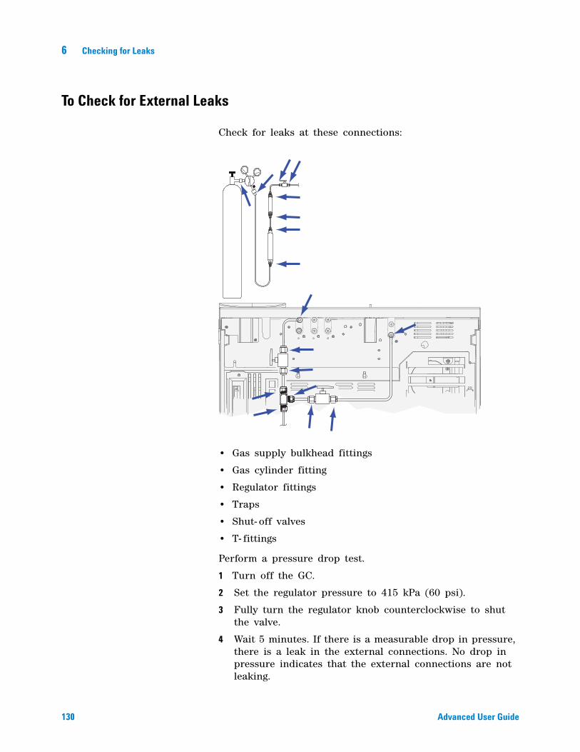
130 Advanced User Guide
6 Checking for Leaks
To Check for External Leaks
Check for leaks at these connections:
• Gas supply bulkhead fittings
• Gas cylinder fitting
• Regulator fittings
• Traps
• Shut- off valves
• T- fittings
Perform a pressure drop test.
1 Turn off the GC.
2 Set the regulator pressure to 415 kPa (60 psi).
3 Fully turn the regulator knob counterclockwise to shut the valve.
4 Wait 5 minutes. If there is a measurable drop in pressure, there is a leak in the external connections. No drop in pressure indicates that the external connections are not leaking.
Checking for Leaks 6
Advanced User Guide 131
To Check for GC Leaks
Check for leaks at these connections:
• Inlet septum, septum head, liner, split vent trap, split vent trap line, and purge vent fittings
• Column connections to inlets, detectors, valves, splitters, and unions
• Fittings from the flow modules to the inlets, detectors, and valves
• Column adapters
• Agilent capillary flow fittings
132 Advanced User Guide
6 Checking for Leaks
Leaks in Capillary Flow Technology (CFT) Fittings
For CFT capillary column fittings, a leak usually indicates that the fitting has been overtightened. Unless the fitting is obviously loose, do not tighten it further. Instead, remove the connection, trim the column end, and install it again.
Also inspect the plate and connection for a broken column tip.
Checking for Leaks 6
Advanced User Guide 133
To Perform a SS Inlet Pressure Decay Test
The pressure decay test checks for leaks from the inlet flow module up to the column fitting.
After performing maintenance, first check for leaks in externally accessible areas. See “To Check for External Leaks”.
If a leak is known to exist, check the externally accessible inlet fittings first, especially any connection that has seen recent maintenance, such as the septum nut, column adapter, column connection, and so forth.
The pressure decay leak test described below requires removing the column and capping the inlet column fitting. This test can/cannot find the following types of leaks:
1 Gather the following (see Consumables and parts for the split/splitless inlet):
• No- hole ferrule
• 1/4- inch wrench
• Heat- resistant gloves (if the inlet is hot)
• Column nut
The test can find leaks at the: The test cannot find leaks at the:
septum column fitting
septum nut gas supply bulkhead fittings to the flow module
liner O-ring seal tubing and connections in a transfer line connected to the inlet
gold seal/washer and reducing nut internal leaks in an EPC module (septum purge valve)
inlet body
flow manifold split vent valve
flow manifold septum purge valve
split vent tubing and trap
septum purge tubing
seals within the tubing between the inlet flow module and the inlet body
134 Advanced User Guide
6 Checking for Leaks
• New septum
• O- ring
• ECD/TCD Detector plug (part no. 5060- 9055)
2 Load the inlet maintenance method and wait for the GC to become ready.
3 Remove the column, if installed.
4 Plug the column fitting with a column nut and a no- hole ferrule.
5 Remove the old septum and replace it with a new one. See To change the septum on the split/splitless inlet.
6 Inspect the O- ring and replace it if it is hard and brittle or cracked. See To change the liner and O- ring on the split/splitless inlet.
7 Set the inlet to Split Mode.
8 Configure the column as Inlet: Unspecified.
9 Set the inlet temperature to 70 °C.
10 Set the Total flow to 60 mL/min.
11 Enter a pressure setpoint of 25 psi (172 kPa). Make sure that the pressure supplied to the GC is at least 10 psi (70 kPa) higher than the inlet pressure.
12 If pressure cannot be achieved, there is either a large leak or the supply pressure is too low.
13 Set the Septum purge flow to 3.0 mL/min.
14 Allow the inlet temperature to stabilize. Temperature changes can invalidate the test.
15 Cap the septum purge fitting with the ECD/TCD detector plug.
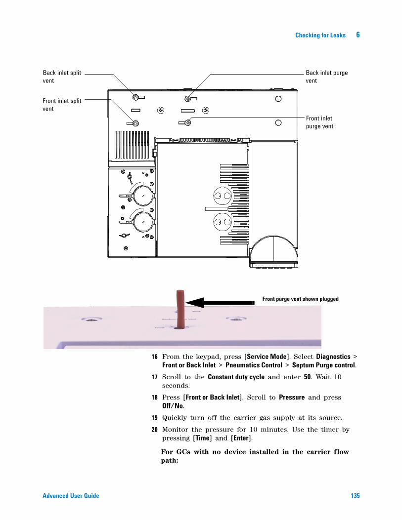
Checking for Leaks 6
Advanced User Guide 135
16 From the keypad, press [Service Mode]. Select Diagnostics > Front or Back Inlet > Pneumatics Control > Septum Purge control.
17 Scroll to the Constant duty cycle and enter 50. Wait 10 seconds.
18 Press [Front or Back Inlet]. Scroll to Pressure and press Off/No.
19 Quickly turn off the carrier gas supply at its source.
20 Monitor the pressure for 10 minutes. Use the timer by pressing [Time] and [Enter].
For GCs with no device installed in the carrier flow path:
Back inlet purge vent
Front inlet purge vent
Back inlet split vent
Front inlet split vent
Front purge vent shown plugged
136 Advanced User Guide
6 Checking for Leaks
A pressure drop of less than 0.5 psig (0.05 psi/min or less; 3.4 kPa or 0.34 kPa/min) is acceptable.
If the pressure drops much faster than the acceptable rate, see “To Correct Leaks in the Split Splitless Inlet”. Retest.
For a GC with a 7697A Headspace Sampler:
A pressure drop of less than 1.7 psig (0.17 psi/min or less; 11.7 kPa or 1.17 kPa/min) is acceptable. If the 7697A passes all its leak tests (restriction, pressure decay, and cross port), and if the GC inlet pressure decay test passes without the 7697A installed, check the 7697A carrier flow path. See the Headspace Sampler documentation.
For a GC with a G1888 Headspace Sampler:
A pressure drop of less than 2 psig in 5 minutes (0.4 psi/min or less; 13.8 kPa or 2.76 kPa/min) is acceptable when using a 1 cc sample loop.
For all GCs:
Note that liner size impacts pressure drop. An inlet with a smaller volume liner does not tolerate as large a leak rate as an inlet with a larger volume liner.
21 After the inlet passes the test, restore the GC to operating condition.
• Remove any caps/plugs.
• Reinstall the column.
• Restore the correct column configuration.
• Load the operating method.
Checking for Leaks 6
Advanced User Guide 137
To Correct Leaks in the Split Splitless Inlet
If the inlet fails a pressure decay test, check the following:
• Check the caps/plugs used in the test—make sure each is correctly installed and tight.
• If you performed the leak test after performing maintenance, check for proper installation of the part(s) handled during the maintenance.
• Check the tightness of the septum nut. See To change the septum on the split/Splitless inlet.
• Check the septum. Replace if old or damaged.
• Check the insert assembly installation.
• Check the liner and liner O- ring. See To change the liner and O- ring on the split/splitless inlet.
• If you changed the gold seal, verify correct installation. See To replace the gold seal on the split/splitless inlet.
• Make sure the inlet temperature remained constant during the test.
If these items do not resolve the problem, contact Agilent for service.
138 Advanced User Guide
6 Checking for Leaks
To Perform a Multimode Inlet Pressure Decay Test
The pressure decay test checks for leaks from the inlet flow module up to the column fitting.
After performing maintenance, first check for leaks in externally accessible areas. See “To Check for External Leaks”.
If a leak is known to exist, check the externally accessible inlet fittings first, especially any connection that has seen recent maintenance, such as the septum nut, column adapter, column connection, and so forth.
The pressure decay leak test described below requires removing the column and capping the inlet column fitting. This test can/cannot find the following types of leaks:
1 Gather the following (see Consumables and parts for the Multimode inlet):
• No- hole ferrule
• 1/4- inch wrench
• Heat- resistant gloves (if the inlet is hot)
• Column nut
• New septum
• O- ring
The test can find leaks at the: The test cannot find leaks at the:
septum column fitting
septum nut gas supply bulkhead fittings to the flow module
liner O-ring seal tubing and connections in a transfer line connected to the inlet
inlet body
flow manifold split vent valve
flow manifold septum purge valve
split vent tubing and trap
septum purge tubing
seals within the tubing between the inlet flow module and the inlet body
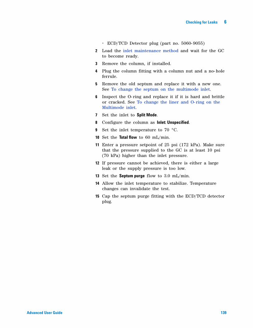
Checking for Leaks 6
Advanced User Guide 139
• ECD/TCD Detector plug (part no. 5060- 9055)
2 Load the inlet maintenance method and wait for the GC to become ready.
3 Remove the column, if installed.
4 Plug the column fitting with a column nut and a no- hole ferrule.
5 Remove the old septum and replace it with a new one. See To change the septum on the multimode inlet.
6 Inspect the O- ring and replace it if it is hard and brittle or cracked. See To change the liner and O- ring on the Multimode inlet.
7 Set the inlet to Split Mode.
8 Configure the column as Inlet: Unspecified.
9 Set the inlet temperature to 70 °C.
10 Set the Total flow to 60 mL/min.
11 Enter a pressure setpoint of 25 psi (172 kPa). Make sure that the pressure supplied to the GC is at least 10 psi (70 kPa) higher than the inlet pressure.
12 If pressure cannot be achieved, there is either a large leak or the supply pressure is too low.
13 Set the Septum purge flow to 3.0 mL/min.
14 Allow the inlet temperature to stabilize. Temperature changes can invalidate the test.
15 Cap the septum purge fitting with the ECD/TCD detector plug.
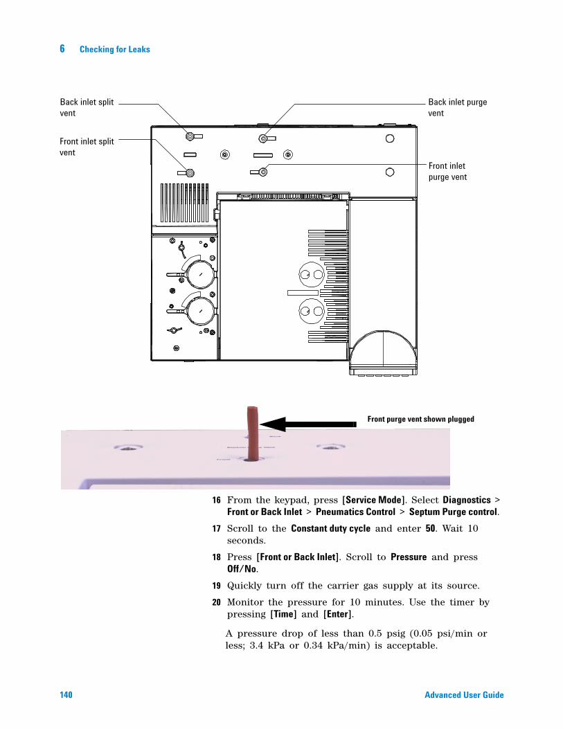
140 Advanced User Guide
6 Checking for Leaks
16 From the keypad, press [Service Mode]. Select Diagnostics > Front or Back Inlet > Pneumatics Control > Septum Purge control.
17 Scroll to the Constant duty cycle and enter 50. Wait 10 seconds.
18 Press [Front or Back Inlet]. Scroll to Pressure and press Off/No.
19 Quickly turn off the carrier gas supply at its source.
20 Monitor the pressure for 10 minutes. Use the timer by pressing [Time] and [Enter].
A pressure drop of less than 0.5 psig (0.05 psi/min or less; 3.4 kPa or 0.34 kPa/min) is acceptable.
Back inlet purge vent
Front inlet purge vent
Back inlet split vent
Front inlet split vent
Front purge vent shown plugged
Checking for Leaks 6
Advanced User Guide 141
If the pressure drops much faster than the acceptable rate, see “To Correct Leaks in the Multimode Inlet”. Retest.
Note that liner size impacts pressure drop. An inlet with a smaller volume liner does not tolerate as large a leak rate as an inlet with a larger volume liner.
21 After the inlet passes the test, restore the GC to operating condition.
• Remove any caps/plugs.
• Reinstall the column.
• Restore the correct column configuration.
• Load the operating method.
142 Advanced User Guide
6 Checking for Leaks
To Correct Leaks in the Multimode Inlet
If the inlet fails a pressure decay test, check the following:
• Check the caps/plugs used in the test—make sure each is correctly installed and tight.
• If you performed the leak test after performing maintenance, check for proper installation of the part(s) handled during the maintenance.
• Check the tightness of the septum nut. See To change the septum on the Multimode inlet.
• Check the septum. Replace if old or damaged.
• Check the insert assembly installation.
• Check the liner and liner O- ring. See To change the liner and O- ring on the Multimode inlet.
• Make sure the inlet temperature remained constant during the test.
If these items do not resolve the problem, contact Agilent for service.
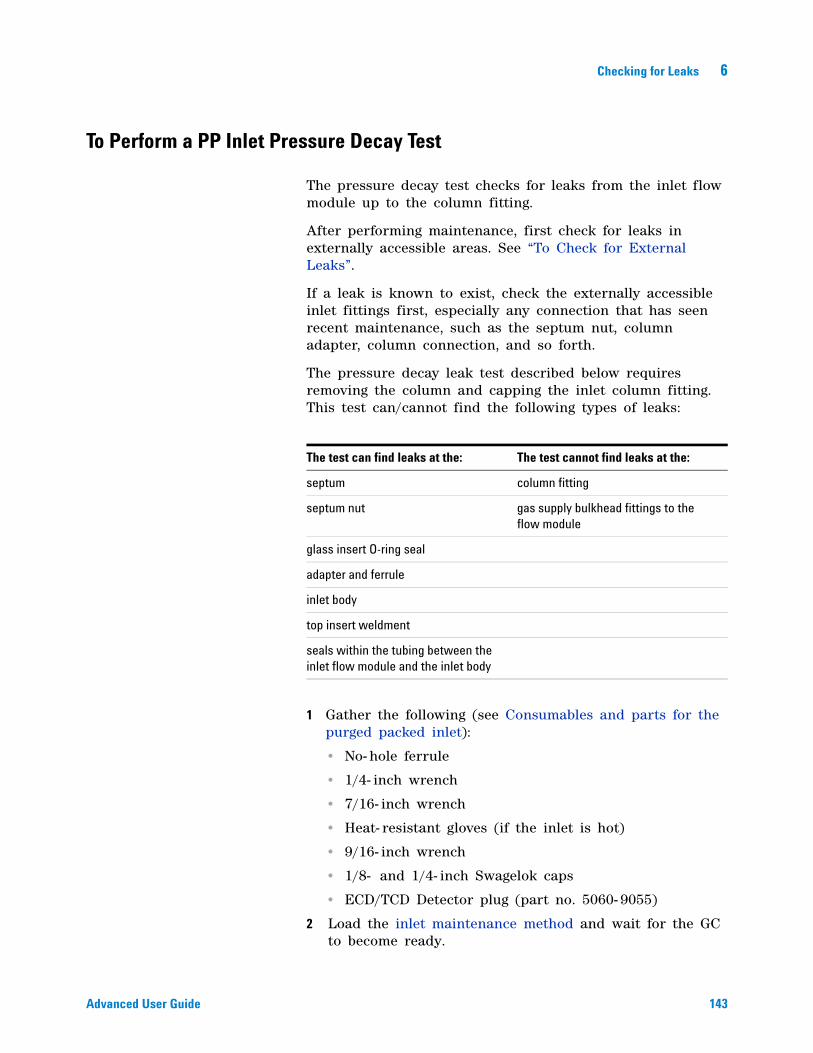
Checking for Leaks 6
Advanced User Guide 143
To Perform a PP Inlet Pressure Decay Test
The pressure decay test checks for leaks from the inlet flow module up to the column fitting.
After performing maintenance, first check for leaks in externally accessible areas. See “To Check for External Leaks”.
If a leak is known to exist, check the externally accessible inlet fittings first, especially any connection that has seen recent maintenance, such as the septum nut, column adapter, column connection, and so forth.
The pressure decay leak test described below requires removing the column and capping the inlet column fitting. This test can/cannot find the following types of leaks:
1 Gather the following (see Consumables and parts for the purged packed inlet):
• No- hole ferrule
• 1/4- inch wrench
• 7/16- inch wrench
• Heat- resistant gloves (if the inlet is hot)
• 9/16- inch wrench
• 1/8- and 1/4- inch Swagelok caps
• ECD/TCD Detector plug (part no. 5060- 9055)
2 Load the inlet maintenance method and wait for the GC to become ready.
The test can find leaks at the: The test cannot find leaks at the:
septum column fitting
septum nut gas supply bulkhead fittings to the flow module
glass insert O-ring seal
adapter and ferrule
inlet body
top insert weldment
seals within the tubing between the inlet flow module and the inlet body
144 Advanced User Guide
6 Checking for Leaks
3 Set the total flow to 40 mL/min and purge the inlet for about 1 minute.
4 Remove the column, if installed.
5 Plug the column fitting.
• If the capillary column adapter is installed, use a column nut and a no- hole ferrule
• If a 1/8- inch packed column adapter is installed, use a 1/8- inch Swagelok cap (5180- 4121).
• If a 1/4- inch packed column adapter is installed, use a 1/4- inch Swagelok cap (5180- 4120)
6 Remove the old septum and replace it with a new one. See To change the septum on the purged packed inlet.
7 Inspect the O- ring and replace it if it is hard and brittle or cracked. See To change the O- ring on the purged packed inlet.
8 If unsure of the quality of the adapter ferrule, replace it. See To change the glass insert on a PP inlet.
9 Configure, but do not install, a capillary column to put the inlet in pressure control mode.
10 Set the inlet temperature to 100 °C.
11 Enter a pressure setpoint of 25 psi (172 kPa). Make sure that the pressure supplied to the GC is at least 10 psi (70 kPa) higher than the inlet pressure.
12 If pressure cannot be achieved, there is either a large leak or the supply pressure is too low.
13 Set the Septum purge flow to 3.0 mL/min.
14 Allow the inlet temperature to stabilize. Temperature changes can invalidate the test.
15 Cap the septum purge fitting with the ECD/TCD detector plug.
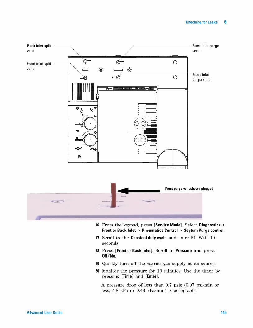
Checking for Leaks 6
Advanced User Guide 145
16 From the keypad, press [Service Mode]. Select Diagnostics > Front or Back Inlet > Pneumatics Control > Septum Purge control.
17 Scroll to the Constant duty cycle and enter 50. Wait 10 seconds.
18 Press [Front or Back Inlet]. Scroll to Pressure and press Off/No.
19 Quickly turn off the carrier gas supply at its source.
20 Monitor the pressure for 10 minutes. Use the timer by pressing [Time] and [Enter].
A pressure drop of less than 0.7 psig (0.07 psi/min or less; 4.8 kPa or 0.48 kPa/min) is acceptable.
Back inlet purge vent
Front inlet purge vent
Back inlet split vent
Front inlet split vent
Front purge vent shown plugged
146 Advanced User Guide
6 Checking for Leaks
If the pressure drops much faster than the acceptable rate, see “To Correct Leaks in the Packed Column Inlet”. Retest.
21 After the inlet passes the test, restore the GC to operating condition.
• Remove any caps/plugs.
• Reinstall the column.
• Restore the correct column configuration.
• Load the operating method.
Checking for Leaks 6
Advanced User Guide 147
To Correct Leaks in the Packed Column Inlet
If the inlet fails a pressure decay test, check the following:
• Check the caps/plugs used in the test—make sure each is correctly installed and tight.
• If you performed the leak test after performing maintenance, check for proper installation of the part(s) handled during the maintenance.
• Check the tightness of the septum nut. See To change the septum on the purged packed inlet.
• Check the septum. Replace if old or damaged.
• Check that the top insert weldment is installed tightly.
• Replace the O- ring. See To change the O- ring on the purged packed inlet. Also check the glass insert. See To change the glass insert on a PP inlet.
• Replace the ferrule seal on the adapter.
• Make sure the inlet temperature remained constant during the test.
If these items do not resolve the problem, contact Agilent for service.
148 Advanced User Guide
6 Checking for Leaks
To Perform a COC Pressure Decay Test
The pressure decay test checks for leaks from the inlet flow module up to the column fitting.
After performing maintenance, first check for leaks in externally accessible areas. See “To Check for External Leaks”.
If a leak is known to exist, check the externally accessible inlet fittings first, especially any connection that has seen recent maintenance, such as the septum nut, column adapter, column connection, and so forth. See “To Check for External Leaks”.
The pressure decay leak test described below requires removing the column and capping the inlet column fitting. This test can/cannot find the following types of leaks:
1 Gather the following (see Consumables and parts for the COC inlet):
• No- hole ferrule
• 1/4- inch wrench
• Heat- resistant gloves (if the inlet is hot)
• Column nut
• New septum
• ECD/TCD Detector plug (part no. 5060- 9055)
2 Load the inlet maintenance method and wait for the GC to become ready.
3 Remove the column, if installed.
4 Plug the column fitting with a column nut and no- hole ferrule.
The test can find leaks at the: The test cannot find leaks at the:
septum column fitting
septum nut or cooling tower gas supply bulkhead fittings to the flow module
seals within the tubing between the inlet flow module and the inlet body
inlet body
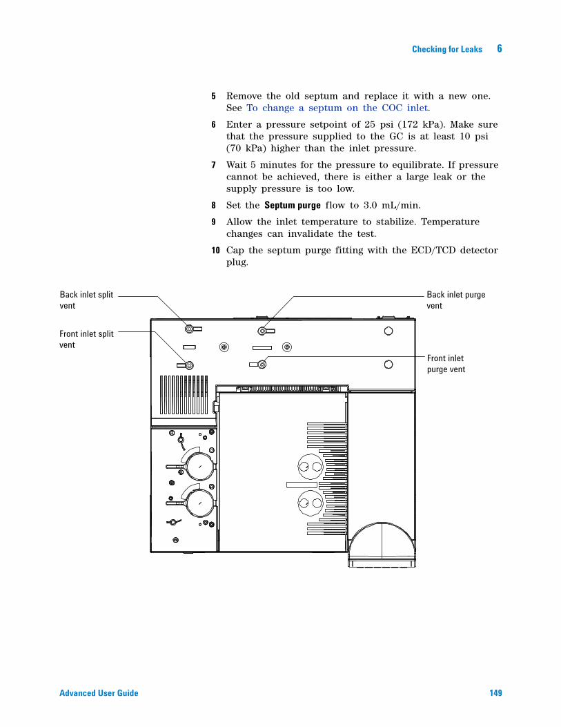
Checking for Leaks 6
Advanced User Guide 149
5 Remove the old septum and replace it with a new one. See To change a septum on the COC inlet.
6 Enter a pressure setpoint of 25 psi (172 kPa). Make sure that the pressure supplied to the GC is at least 10 psi (70 kPa) higher than the inlet pressure.
7 Wait 5 minutes for the pressure to equilibrate. If pressure cannot be achieved, there is either a large leak or the supply pressure is too low.
8 Set the Septum purge flow to 3.0 mL/min.
9 Allow the inlet temperature to stabilize. Temperature changes can invalidate the test.
10 Cap the septum purge fitting with the ECD/TCD detector plug.
Back inlet purge vent
Front inlet purge vent
Back inlet split vent
Front inlet split vent
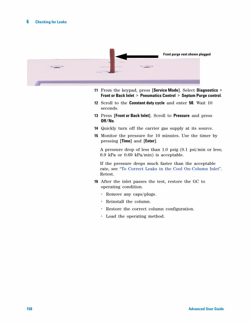
150 Advanced User Guide
6 Checking for Leaks
11 From the keypad, press [Service Mode]. Select Diagnostics > Front or Back Inlet > Pneumatics Control > Septum Purge control.
12 Scroll to the Constant duty cycle and enter 50. Wait 10 seconds.
13 Press [Front or Back Inlet]. Scroll to Pressure and press Off/No.
14 Quickly turn off the carrier gas supply at its source.
15 Monitor the pressure for 10 minutes. Use the timer by pressing [Time] and [Enter].
A pressure drop of less than 1.0 psig (0.1 psi/min or less; 6.9 kPa or 0.69 kPa/min) is acceptable.
If the pressure drops much faster than the acceptable rate, see “To Correct Leaks in the Cool On- Column Inlet”. Retest.
16 After the inlet passes the test, restore the GC to operating condition.
• Remove any caps/plugs.
• Reinstall the column.
• Restore the correct column configuration.
• Load the operating method.
Front purge vent shown plugged
Checking for Leaks 6
Advanced User Guide 151
To Correct Leaks in the Cool On-Column Inlet
If the inlet fails a pressure decay test, check the following:
• Check the caps/plugs used in the test—make sure each is correctly installed and tight.
• If you performed the leak test after performing maintenance, check for proper installation of the part(s) handled during the maintenance.
• Check the tightness of the septum nut or cooling tower assembly. See To change a septum nut or cooling tower and septum on a COC inlet.
• Check the septum. Replace if old or damaged.
• Make sure the inlet temperature remained constant during the test.
If these items do not resolve the problem, contact Agilent for service.
152 Advanced User Guide
6 Checking for Leaks
To Perform a PTV Pressure Decay Test
The pressure decay test checks for leaks from the inlet flow module up to the column fitting.
After performing maintenance, first check for leaks in externally accessible areas. See “To Check for External Leaks”.
If a leak is known to exist, check the externally accessible inlet fittings first, especially any connection that has seen recent maintenance, such as the septum nut, column adapter, column connection, and so forth.
The pressure decay leak test described below requires removing the column and capping the inlet column fitting. This test can/cannot find the following types of leaks:
1 Gather the following (see Consumables and parts for the PTV inlet):
• No- hole ferrule
• 1/4- inch wrench
• Heat- resistant gloves (if the inlet is hot)
• Column nut
• New septum
The test can find leaks at the: The test cannot find leaks at the:
septum column fitting
septum nut gas supply bulkhead fittings to the flow module
liner O-ring seal tubing and connections in a transfer line connected to the inlet
gold seal/washer and reducing nut
inlet body
flow manifold split vent valve
flow manifold septum purge valve
split vent tubing and trap
septum purge tubing
seals within the tubing between the inlet flow module and the inlet body
Checking for Leaks 6
Advanced User Guide 153
• New Graphpak 3D ferrule and liner
• ECD/TCD Detector plug (part no. 5060- 9055)
2 Load the inlet maintenance method and wait for the GC to become ready.
3 Remove the column, if installed.
4 Plug the column fitting with a column nut and a no- hole ferrule.
5 If using the septum head, and the quality of the septum (or Microseal) and GRAPHPACK- 3D ferrule on the glass liner are unknown, replace them now. See To change the septum on the PTV inlet and To change the liner on the PTV inlet.
6 Set the inlet to Split Mode.
7 Configure the column as 0 length.
8 Set the inlet temperature to 100 °C.
9 Set the Total flow to 60 mL/min.
10 Enter a pressure setpoint of 25 psi (172 kPa). Make sure that the pressure supplied to the GC is at least 10 psi (70 kPa) higher than the inlet pressure.
11 If pressure cannot be achieved, there is either a large leak or the supply pressure is too low.
12 Set the Septum purge flow to 3.0 mL/min.
13 Allow the inlet temperature to stabilize. Temperature changes can invalidate the test.
14 Cap the septum purge fitting with the ECD/TCD detector plug.
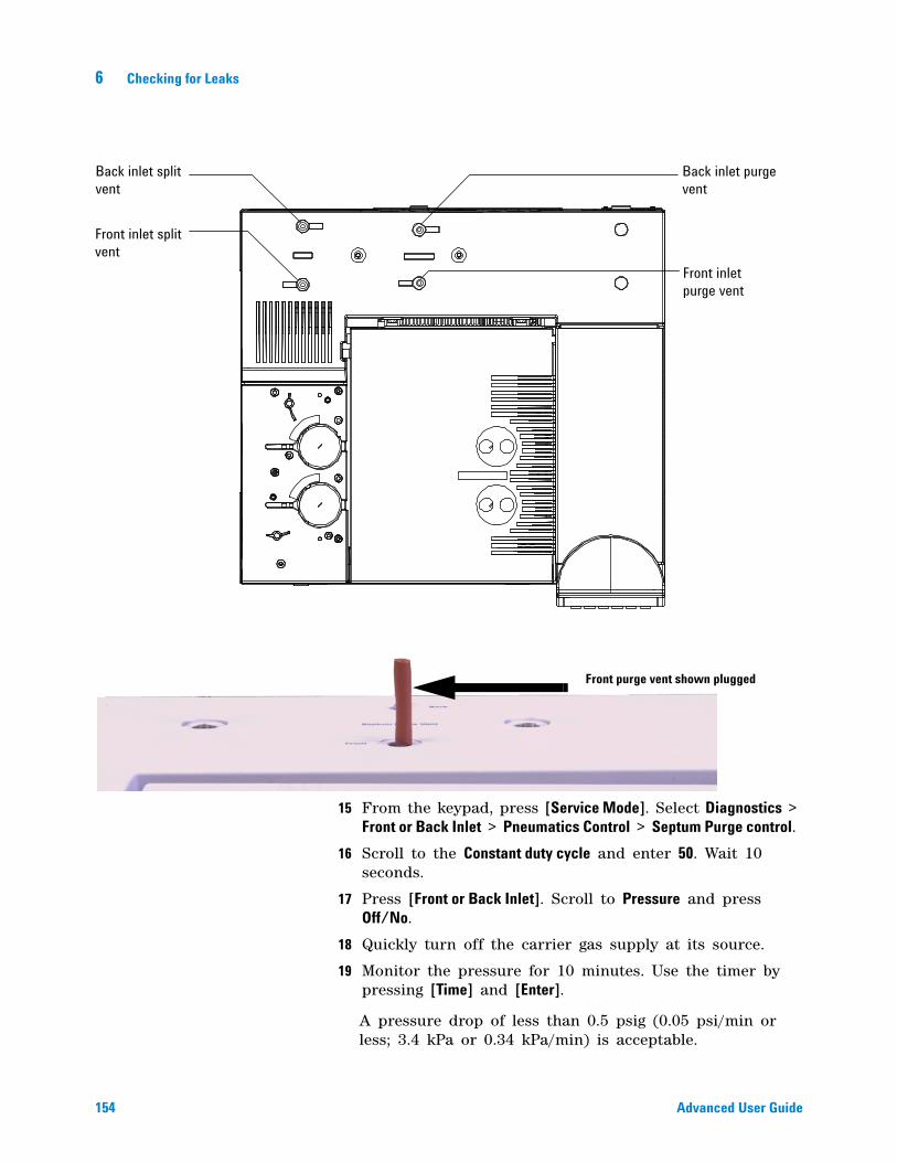
154 Advanced User Guide
6 Checking for Leaks
15 From the keypad, press [Service Mode]. Select Diagnostics > Front or Back Inlet > Pneumatics Control > Septum Purge control.
16 Scroll to the Constant duty cycle and enter 50. Wait 10 seconds.
17 Press [Front or Back Inlet]. Scroll to Pressure and press Off/No.
18 Quickly turn off the carrier gas supply at its source.
19 Monitor the pressure for 10 minutes. Use the timer by pressing [Time] and [Enter].
A pressure drop of less than 0.5 psig (0.05 psi/min or less; 3.4 kPa or 0.34 kPa/min) is acceptable.
Back inlet purge vent
Front inlet purge vent
Back inlet split vent
Front inlet split vent
Front purge vent shown plugged
Checking for Leaks 6
Advanced User Guide 155
If the pressure drops much faster than the acceptable rate, see “To Correct Leaks in the PTV Inlet”. Retest.
Note that liner size impacts pressure drop. An inlet with a smaller volume liner does not tolerate as large a leak rate as an inlet with a larger volume liner.
20 After the inlet passes the test, restore the GC to operating condition.
• Remove any caps/plugs.
• Reinstall the column.
• Restore the correct column configuration.
• Load the operating method.
156 Advanced User Guide
6 Checking for Leaks
To Correct Leaks in the PTV Inlet
If the inlet fails a pressure decay test, check the following:
• Check the caps/plugs used in the test—make sure each is correctly installed and tight.
• If you performed the leak test after performing maintenance, check for proper installation of the part(s) handled during the maintenance.
• If using a septum head, check the tightness of the septum nut. See To change the septum on the PTV inlet.
• If using a septum head, check the septum. Replace if old or damaged.
• Check that the septumless- or septum- head assembly is installed tightly.
• Replace the liner and Graphpak 3D ferrule. See To change the liner on the PTV inlet.
• Check the Graphpak adapter seal against the inlet body. Replace the silver seal and reinstall the adapter if needed. See To replace the inlet adapter for the PTV inlet.
• If using the septumless head, check for leaks around the guide cap. Replace the PTFE ferrule in the guide cap. See To replace the PTFE ferrule on a PTV inlet.
• Check for leaks at the split vent trap. Tighten as necessary. Replace the split vent trap filter and O- rings. See To replace the filter in the PTV inlet split vent line.
• Make sure the inlet temperature remained constant during the test.
If these items not resolve the problem, contact Agilent for service.
Checking for Leaks 6
Advanced User Guide 157
To Perform a VI Pressure Decay Test
The pressure decay test checks for leaks from the inlet flow module up to the column fitting.
Initially test the VI with a sampling system installed. If the system fails the leak test, then isolate the VI from the sampler as described in “To Prepare the VI for a Closed System Leak Check” on page 161.
After performing maintenance, first check for leaks in externally accessible areas. See “To Check for External Leaks”.
If a leak is known to exist, check the externally accessible inlet fittings first, especially any connection that has seen recent maintenance, such as the column connection, split vent line, and so forth.
The pressure decay leak test described below requires removing the column and capping the inlet column fitting. This test can/cannot find the following types of leaks:
1 Gather the following (see Consumables and parts for the VI):
• No- hole ferrule
• 1/4- inch wrench
• Heat- resistant gloves (if the inlet is hot)
• Long column nut
• ECD/TCD Detector plug (part no. 5060- 9055)
The test can find leaks at the: The test cannot find leaks at the:
sampler connection column fitting
pressure sensing line connection to the interface
gas supply bulkhead fittings to the flow module
split vent line connection to the interface
tubing and connections in a transfer line connected to the inlet
the connected sampler’s entire sample flow path
flow manifold split vent valve
flow manifold septum purge valve
split vent tubing and trap
158 Advanced User Guide
6 Checking for Leaks
2 Load the inlet maintenance method and wait for the GC to become ready.
3 Remove the column, if installed.
4 Plug the column fitting with a column nut and a no- hole ferrule.
5 Set the inlet to Split Mode.
6 Configure the column as 0 length.
7 Set the inlet temperature to 100 °C.
8 Set the Total flow to 60 mL/min.
9 Enter a pressure setpoint of 25 psi (172 kPa). Make sure that the pressure supplied to the GC is at least 10 psi (70 kPa) higher than the inlet pressure.
10 If pressure cannot be achieved, there is either a large leak or the supply pressure is too low.
11 Set the Septum purge flow to 3.0 mL/min.
12 Allow the inlet temperature to stabilize. Temperature changes can invalidate the test.
13 Cap the septum purge fitting with the ECD/TCD detector plug.
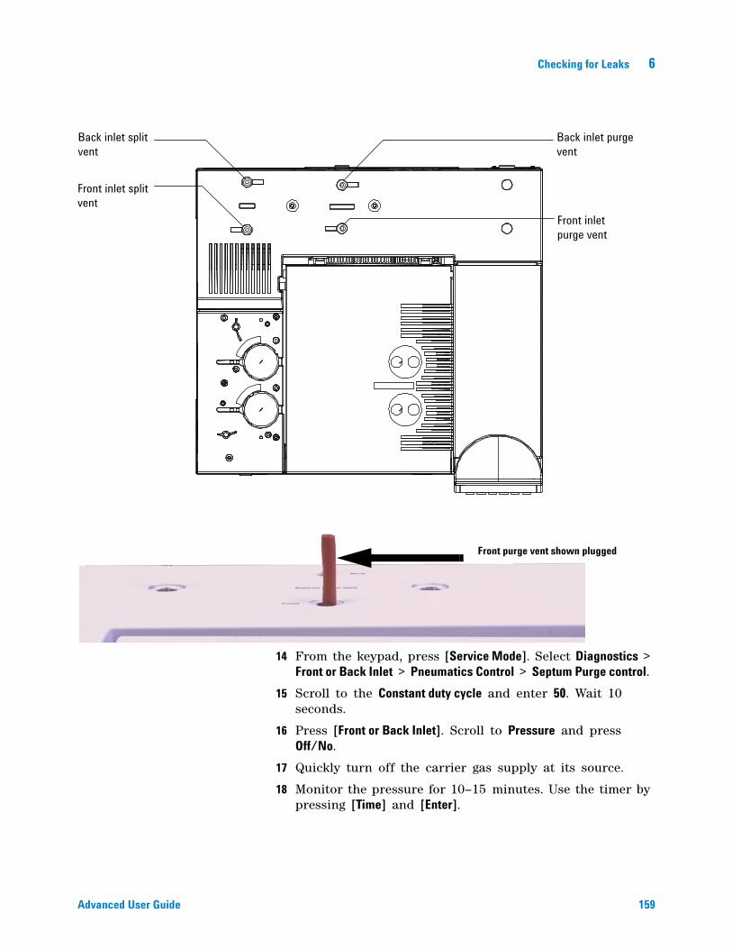
Checking for Leaks 6
Advanced User Guide 159
14 From the keypad, press [Service Mode]. Select Diagnostics > Front or Back Inlet > Pneumatics Control > Septum Purge control.
15 Scroll to the Constant duty cycle and enter 50. Wait 10 seconds.
16 Press [Front or Back Inlet]. Scroll to Pressure and press Off/No.
17 Quickly turn off the carrier gas supply at its source.
18 Monitor the pressure for 10–15 minutes. Use the timer by pressing [Time] and [Enter].
Back inlet purge vent
Front inlet purge vent
Back inlet split vent
Front inlet split vent
Front purge vent shown plugged
160 Advanced User Guide
6 Checking for Leaks
The pressure should drop approximately 1 psi (6.9 kPa) during the first 1 to 2 minutes. After an initial pressure drop of about 1 psi, the pressure should not drop more than 0.03 psi/min (0.21 kPa/min).
If the pressure drop is 0.03 psi/min or less, you can consider the interface- gas sampler system leak- free.
If the pressure drops faster than the acceptable rate, you must check the interface and sampler systems separately to determine the source of the leak. See “To Prepare the VI for a Closed System Leak Check” to create a closed flow system, then return to this section and complete steps 10 to 16.
If you find a leak in the interface, refer to “To Correct Leaks in the Volatiles Interface”.
If the interface is leak- free, pressure check the sampling device. See the operating manual for your sampler for instructions.
19 After the VI passes the test, restore the GC to operating condition.
• Remove any caps/plugs.
• If needed, reconnect the sampling device.
• Reinstall the column.
• Restore the correct column configuration.
• Load the operating method.
Checking for Leaks 6
Advanced User Guide 161
To Prepare the VI for a Closed System Leak Check
To leak check the interface independently of the gas sampling device, you must disconnect the sampler from the interface to isolate the interface flow system from the sampler.
1 Gather the following:
• 1/16- inch nut for transfer line
• Ferrule for transfer line
• Heat- resistant gloves (if the inlet is hot)
2 Disconnect the transfer line from the interface.
3 Disconnect the carrier line from the sampler.
4 Prepare the end of the carrier line using a 1/16- inch male nut and ferrule.
5 Connect the carrier line to the interface where you removed the transfer line and tighten the nut finger tight. Tighten an additional 1/4 to 1/2 turn with the 1/4- inch wrench.
6 Return to “To Perform a VI Pressure Decay Test” and repeat steps 9 to 16.
WARNING Be careful! The oven and/or inlet may be hot enough to cause burns. If either is hot, wear heat-resistant gloves to protect your hands.
162 Advanced User Guide
6 Checking for Leaks
To Correct Leaks in the Volatiles Interface
If the inlet fails a pressure decay test, check the following:
• The caps and plugs used in the test—make sure each is correctly installed and tight.
• If you performed the leak test after performing maintenance, check for proper installation of the part(s) handled during the maintenance.
• The split vent and pressure sensing connections at the interface.
• The sampler connection to the interface.
• The sampler.
If these items do not resolve the problem, contact Agilent for service.
163
Agilent 7890A Gas ChromatographAdvanced User Guide
Agilent Technologies
7Flow and Pressure Modules
About Flow and Pressure Control 164
Maximum operating pressure 164
PIDs 165
Inlet Modules 166
Detector Modules 167
Pressure Control Modules 168
Auxiliary Pressure Controllers 171
Restrictors 172
1. Using an Aux EPC channel to supply purge gas to a splitter 174
2. Using the PCM channels 174
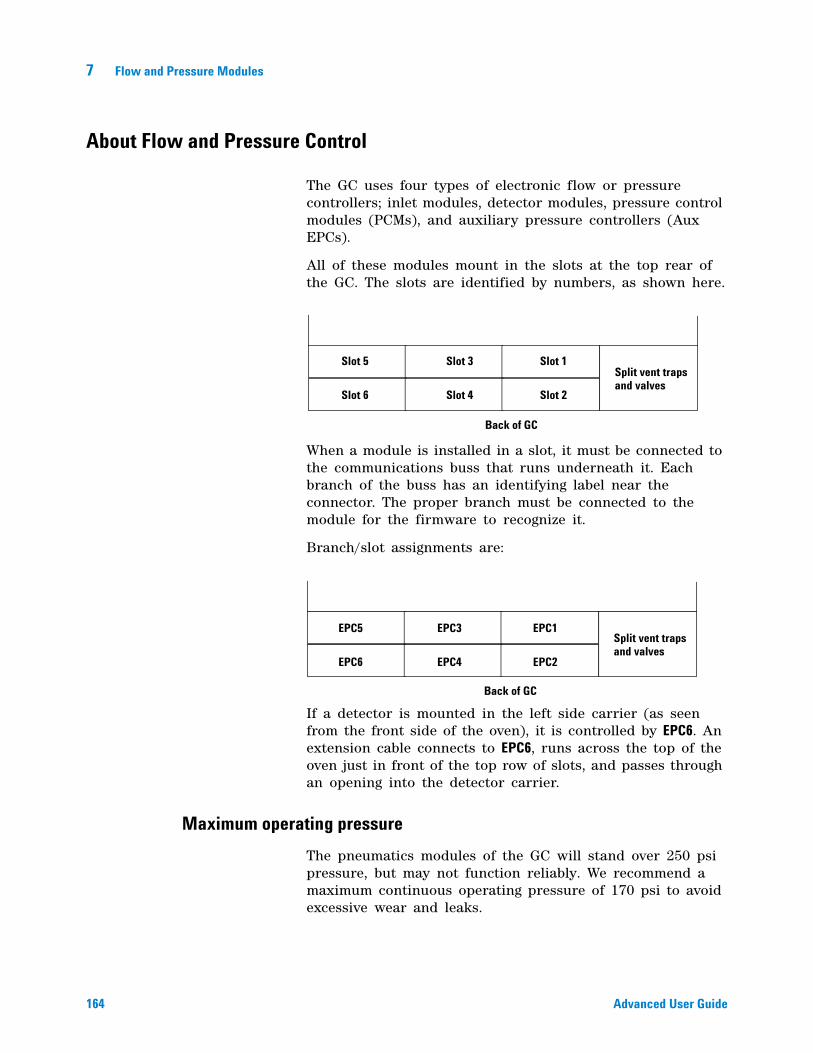
164 Advanced User Guide
7 Flow and Pressure Modules
About Flow and Pressure Control
The GC uses four types of electronic flow or pressure controllers; inlet modules, detector modules, pressure control modules (PCMs), and auxiliary pressure controllers (Aux EPCs).
All of these modules mount in the slots at the top rear of the GC. The slots are identified by numbers, as shown here.
When a module is installed in a slot, it must be connected to the communications buss that runs underneath it. Each branch of the buss has an identifying label near the connector. The proper branch must be connected to the module for the firmware to recognize it.
Branch/slot assignments are:
If a detector is mounted in the left side carrier (as seen from the front side of the oven), it is controlled by EPC6. An extension cable connects to EPC6, runs across the top of the oven just in front of the top row of slots, and passes through an opening into the detector carrier.
Maximum operating pressure
The pneumatics modules of the GC will stand over 250 psi pressure, but may not function reliably. We recommend a maximum continuous operating pressure of 170 psi to avoid excessive wear and leaks.
Split vent trapsand valves
Back of GC
Slot 1
Slot 2
Slot 3
Slot 4
Slot 5
Slot 6
Split vent trapsand valves
Back of GC
EPC1
EPC2
EPC3
EPC4
EPC5
EPC6
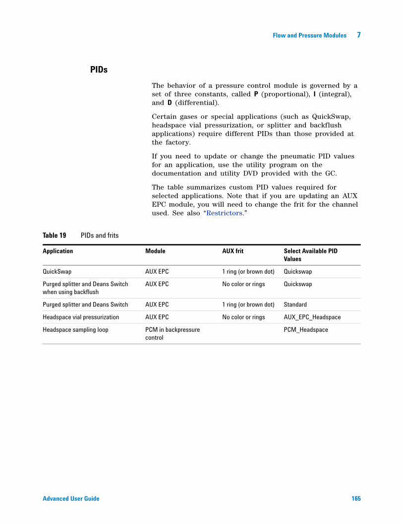
Flow and Pressure Modules 7
Advanced User Guide 165
PIDs
The behavior of a pressure control module is governed by a set of three constants, called P (proportional), I (integral), and D (differential).
Certain gases or special applications (such as QuickSwap, headspace vial pressurization, or splitter and backflush applications) require different PIDs than those provided at the factory.
If you need to update or change the pneumatic PID values for an application, use the utility program on the documentation and utility DVD provided with the GC.
The table summarizes custom PID values required for selected applications. Note that if you are updating an AUX EPC module, you will need to change the frit for the channel used. See also “Restrictors.”
Table 19 PIDs and frits
Application Module AUX frit Select Available PID Values
QuickSwap AUX EPC 1 ring (or brown dot) Quickswap
Purged splitter and Deans Switch when using backflush
AUX EPC No color or rings Quickswap
Purged splitter and Deans Switch AUX EPC 1 ring (or brown dot) Standard
Headspace vial pressurization AUX EPC No color or rings AUX_EPC_Headspace
Headspace sampling loop PCM in backpressure control
PCM_Headspace
166 Advanced User Guide
7 Flow and Pressure Modules
Inlet Modules
These modules are used with specific inlets. They provide a controlled flow or pressure of carrier gas to the inlet and control the septum flow rate.
Module locations depend on the type of module and the length of the tubing connecting it to the inlet.
If you have a Front inlet, its flow module must go in Slot 1.
If you have a Back inlet, its flow module must go in Slot 2.
Flow and Pressure Modules 7
Advanced User Guide 167
Detector Modules
These are specific to the detector with which they are supplied, and differ according to the needs of that detector. For example, the FID module must supply controlled amounts of air, hydrogen, and makeup gas. The TCD module supplies the reference and makeup gases, but includes the reference switching valve that is essential to detector operation.
Module locations depend on the type of module and the length of the tubing connecting it to the detector.
If you have a Front detector, its flow module must go in Slot 3.
If you have a Back detector, its flow module must go in Slot 4.
If you have a TCD detector mounted on the left side of the GC, its flow module mounts in a special bracket near the detector.
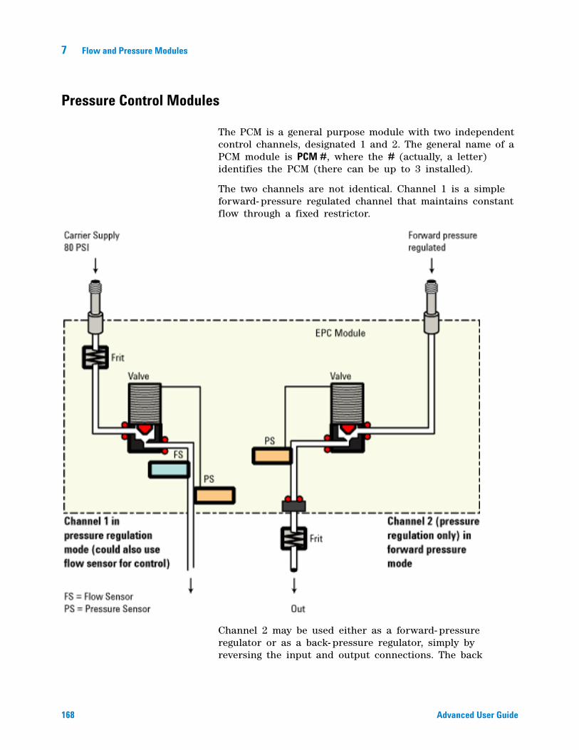
168 Advanced User Guide
7 Flow and Pressure Modules
Pressure Control Modules
The PCM is a general purpose module with two independent control channels, designated 1 and 2. The general name of a PCM module is PCM #, where the # (actually, a letter) identifies the PCM (there can be up to 3 installed).
The two channels are not identical. Channel 1 is a simple forward- pressure regulated channel that maintains constant flow through a fixed restrictor.
Channel 2 may be used either as a forward- pressure regulator or as a back- pressure regulator, simply by reversing the input and output connections. The back
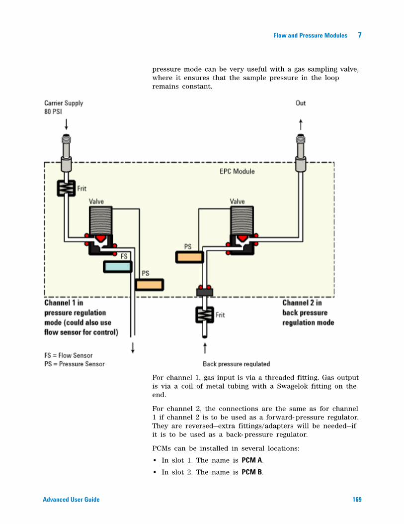
Flow and Pressure Modules 7
Advanced User Guide 169
pressure mode can be very useful with a gas sampling valve, where it ensures that the sample pressure in the loop remains constant.
For channel 1, gas input is via a threaded fitting. Gas output is via a coil of metal tubing with a Swagelok fitting on the end.
For channel 2, the connections are the same as for channel 1 if channel 2 is to be used as a forward- pressure regulator. They are reversed—extra fittings/adapters will be needed—if it is to be used as a back- pressure regulator.
PCMs can be installed in several locations:
• In slot 1. The name is PCM A.
• In slot 2. The name is PCM B.
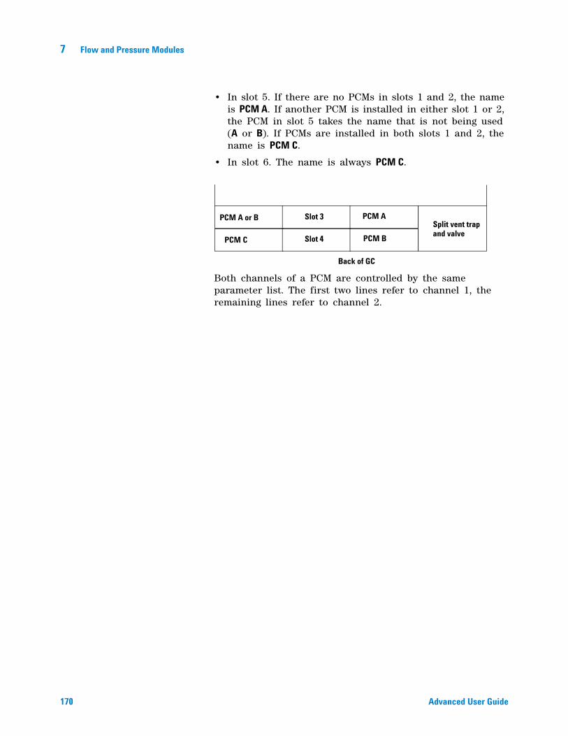
170 Advanced User Guide
7 Flow and Pressure Modules
• In slot 5. If there are no PCMs in slots 1 and 2, the name is PCM A. If another PCM is installed in either slot 1 or 2, the PCM in slot 5 takes the name that is not being used (A or B). If PCMs are installed in both slots 1 and 2, the name is PCM C.
• In slot 6. The name is always PCM C.
Both channels of a PCM are controlled by the same parameter list. The first two lines refer to channel 1, the remaining lines refer to channel 2.
Split vent trapand valve
Slot 3
Slot 4
Back of GC
PCM C
PCM A
PCM B
PCM A or B
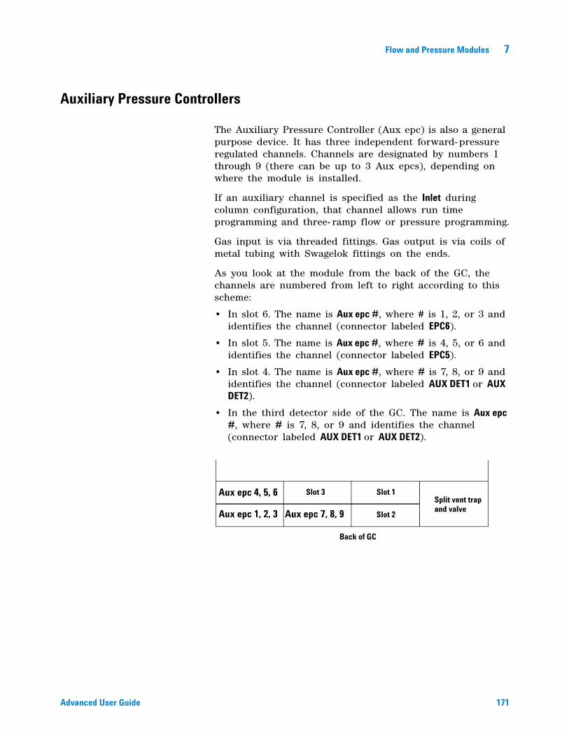
Flow and Pressure Modules 7
Advanced User Guide 171
Auxiliary Pressure Controllers
The Auxiliary Pressure Controller (Aux epc) is also a general purpose device. It has three independent forward- pressure regulated channels. Channels are designated by numbers 1 through 9 (there can be up to 3 Aux epcs), depending on where the module is installed.
If an auxiliary channel is specified as the Inlet during column configuration, that channel allows run time programming and three- ramp flow or pressure programming.
Gas input is via threaded fittings. Gas output is via coils of metal tubing with Swagelok fittings on the ends.
As you look at the module from the back of the GC, the channels are numbered from left to right according to this scheme:
• In slot 6. The name is Aux epc #, where # is 1, 2, or 3 and identifies the channel (connector labeled EPC6).
• In slot 5. The name is Aux epc #, where # is 4, 5, or 6 and identifies the channel (connector labeled EPC5).
• In slot 4. The name is Aux epc #, where # is 7, 8, or 9 and identifies the channel (connector labeled AUX DET1 or AUX DET2).
• In the third detector side of the GC. The name is Aux epc #, where # is 7, 8, or 9 and identifies the channel (connector labeled AUX DET1 or AUX DET2).
Split vent trapand valve
Slot 1
Slot 2
Slot 3
Back of GC
Aux epc 1, 2, 3
Aux epc 4, 5, 6
Aux epc 7, 8, 9
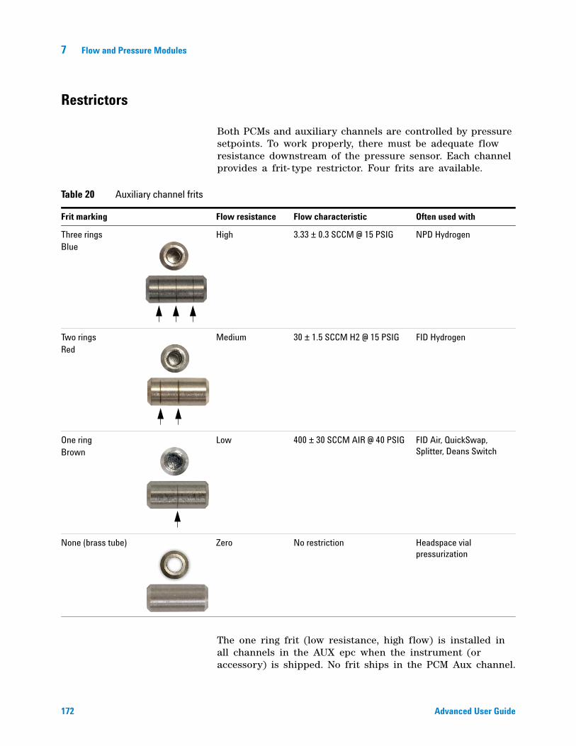
172 Advanced User Guide
7 Flow and Pressure Modules
Restrictors
Both PCMs and auxiliary channels are controlled by pressure setpoints. To work properly, there must be adequate flow resistance downstream of the pressure sensor. Each channel provides a frit- type restrictor. Four frits are available.
The one ring frit (low resistance, high flow) is installed in all channels in the AUX epc when the instrument (or accessory) is shipped. No frit ships in the PCM Aux channel.
Table 20 Auxiliary channel frits
Frit marking Flow resistance Flow characteristic Often used with
Three ringsBlue
High 3.33 ± 0.3 SCCM @ 15 PSIG NPD Hydrogen
Two ringsRed
Medium 30 ± 1.5 SCCM H2 @ 15 PSIG FID Hydrogen
One ringBrown
Low 400 ± 30 SCCM AIR @ 40 PSIG FID Air, QuickSwap, Splitter, Deans Switch
None (brass tube) Zero No restriction Headspace vial pressurization
Flow and Pressure Modules 7
Advanced User Guide 173
When installing or replacing a frit, always use a new O- ring (5180- 4181, 12/pk).
Selecting a frit
The frits change the control range of the channels. The objective is to find a frit that allows the required range of flows at reasonable source pressures.
• For an auxiliary channel ordered as an option (part of the GC order), use the frit supplied by the factory.
• For an auxiliary channel ordered as an accessory (separate from the GC order), see the instruction information supplied with the accessory.
• For a non- Agilent instrument, you must experiment to find the appropriate frit.
When you change a frit, you change the physical characteristics of the channel. It may be desirable (or necessary) to change the PID constants for that channel. See “PIDs” on page 165.
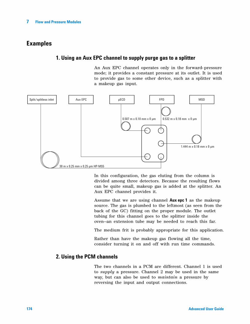
174 Advanced User Guide
7 Flow and Pressure Modules
Examples
1. Using an Aux EPC channel to supply purge gas to a splitter
An Aux EPC channel operates only in the forward- pressure mode; it provides a constant pressure at its outlet. It is used to provide gas to some other device, such as a splitter with a makeup gas input.
In this configuration, the gas eluting from the column is divided among three detectors. Because the resulting flows can be quite small, makeup gas is added at the splitter. An Aux EPC channel provides it.
Assume that we are using channel Aux epc 1 as the makeup source. The gas is plumbed to the leftmost (as seen from the back of the GC) fitting on the proper module. The outlet tubing for this channel goes to the splitter inside the oven—an extension tube may be needed to reach this far.
The medium frit is probably appropriate for this application.
Rather than have the makeup gas flowing all the time, consider turning it on and off with run time commands.
2. Using the PCM channels
The two channels in a PCM are different. Channel 1 is used to supply a pressure. Channel 2 may be used in the same way, but can also be used to maintain a pressure by reversing the input and output connections.
Split/splitless inlet
30 m x 0.25 mm x 0.25 µm HP-MS5
0.507 m x 0.10 mm x 0 µm 0.532 m x 0.18 mm x 0 µm
1.444 m x 0.18 mm x 0 µm
µECDAux EPC FPD MSD
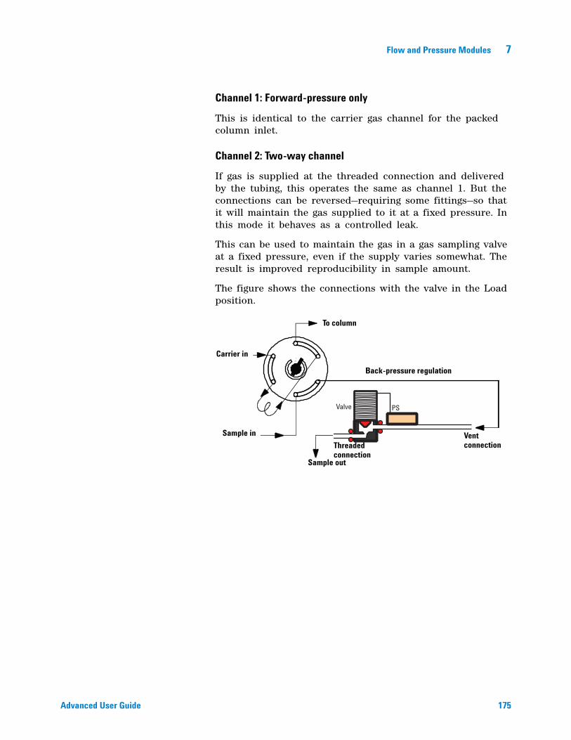
Flow and Pressure Modules 7
Advanced User Guide 175
Channel 1: Forward-pressure only
This is identical to the carrier gas channel for the packed column inlet.
Channel 2: Two-way channel
If gas is supplied at the threaded connection and delivered by the tubing, this operates the same as channel 1. But the connections can be reversed—requiring some fittings—so that it will maintain the gas supplied to it at a fixed pressure. In this mode it behaves as a controlled leak.
This can be used to maintain the gas in a gas sampling valve at a fixed pressure, even if the supply varies somewhat. The result is improved reproducibility in sample amount.
The figure shows the connections with the valve in the Load position.
Valve PS
Sample in
Carrier in
To column
Back-pressure regulation
Sample out
VentconnectionThreaded
connection

176 Advanced User Guide
7 Flow and Pressure Modules
177
Agilent 7890A Gas ChromatographAdvanced User Guide
Agilent Technologies
8InletsUsing Hydrogen 179
Inlet Overview 180
Carrier Gas Flow Rates 181
About Gas Saver 182
Pre Run and Prep Run 184
Auto Prep Run 185
About Heaters 186
About the Split/Splitless Inlet 188
Split/Splitless inlet split mode overview 189
Split/Splitless inlet splitless mode overview 190
The S/SL inlet pulsed split and splitless modes 191
Split/Splitless inlet split mode minimum operating pressures 192
Selecting the correct S/SL inlet liner 193
Vapor Volume Calculator 195
Selecting parameters for the S/SL splitless mode 196
About the Multimode Inlet 199
Septum tightening (MMI) 199
Heating the MMI 200
Cooling the MMI 200
MMI split mode minimum operating pressures 201
Selecting the correct MMI liner 202
Vapor Volume Calculator 204
MMI split and pulsed split modes 204
MMI splitless and pulsed splitless modes 208
MMI solvent vent mode 214
MMI Direct Mode 222
To develop a MMI method that uses large volume injection 223
Multiple injections with the MMI 226
About the Cool On-Column Inlet 236
Retention gaps 237
COC inlet temperature control 237
Setting COC inlet flows/pressures 238
About the PTV Inlet 240
PTV sampling heads 240
Heating the PTV inlet 241
178 Advanced User Guide
8 Inlets
Cooling the PTV inlet 242
PTV inlet split and pulsed split modes 242
PTV inlet splitless and pulsed splitless modes 246
PTV inlet solvent vent mode 253
To develop a PTV method that uses large volume injection 261
Multiple injections with the PTV inlet 264
About the Volatiles Interface 270
About the VI split mode 272
About the VI splitless mode 276
About the VI direct mode 281
Preparing the Interface for Direct Sample Introduction 284
Setting parameters for the VI direct mode 287
Inlets 8
Advanced User Guide 179
Using Hydrogen
WARNING When using hydrogen (H2), as the carrier gas, be aware that hydrogen (H2) gas can flow into the oven and create an explosion hazard. Therefore, be sure that the supply is off until all connections are made, and ensure that the inlet and detector column fittings are either connected to a column or capped at all times when hydrogen (H2) gas is supplied to the instrument.
WARNING Hydrogen (H2) is flammable. Leaks, when confined in an enclosed space, may create a fire or explosion hazard. In any application using hydrogen (H2), leak test all connections, lines, and valves before operating the instrument. Always turn off the hydrogen (H2) supply at its source before working on the instrument.
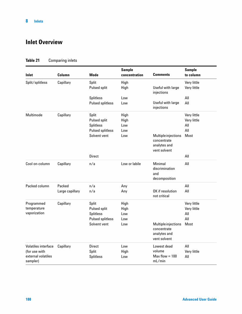
180 Advanced User Guide
8 Inlets
Inlet Overview
Table 21 Comparing inlets
Inlet Column ModeSampleconcentration
Comments
Sampleto column
Split/splitless Capillary SplitPulsed split
SplitlessPulsed splitless
HighHigh
LowLow
Useful with large injections
Useful with large injections
Very littleVery little
AllAll
Multimode Capillary SplitPulsed splitSplitlessPulsed splitlessSolvent vent
Direct
HighHighLowLowLow Multiple injections
concentrate analytes andvent solvent
Very littleVery littleAllAllMost
All
Cool on-column Capillary n/a Low or labile Minimal discriminationand decomposition
All
Packed column PackedLarge capillary
n/an/a
AnyAny OK if resolution
not critical
AllAll
Programmed temperature vaporization
Capillary SplitPulsed splitSplitlessPulsed splitlessSolvent vent
HighHighLowLowLow Multiple injections
concentrate analytes andvent solvent
Very littleVery littleAllAllMost
Volatiles interface(for use with external volatiles sampler)
Capillary DirectSplitSplitless
LowHighLow
Lowest dead volumeMax flow = 100 mL/min
AllVery littleAll
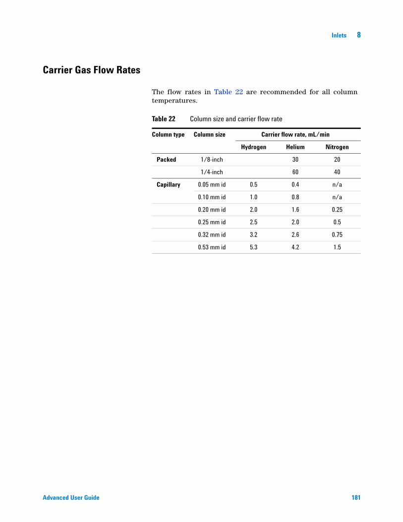
Inlets 8
Advanced User Guide 181
Carrier Gas Flow Rates
The flow rates in Table 22 are recommended for all column temperatures.
Table 22 Column size and carrier flow rate
Column type Column size Carrier flow rate, mL/min
Hydrogen Helium Nitrogen
Packed 1/8-inch 30 20
1/4-inch 60 40
Capillary 0.05 mm id 0.5 0.4 n/a
0.10 mm id 1.0 0.8 n/a
0.20 mm id 2.0 1.6 0.25
0.25 mm id 2.5 2.0 0.5
0.32 mm id 3.2 2.6 0.75
0.53 mm id 5.3 4.2 1.5
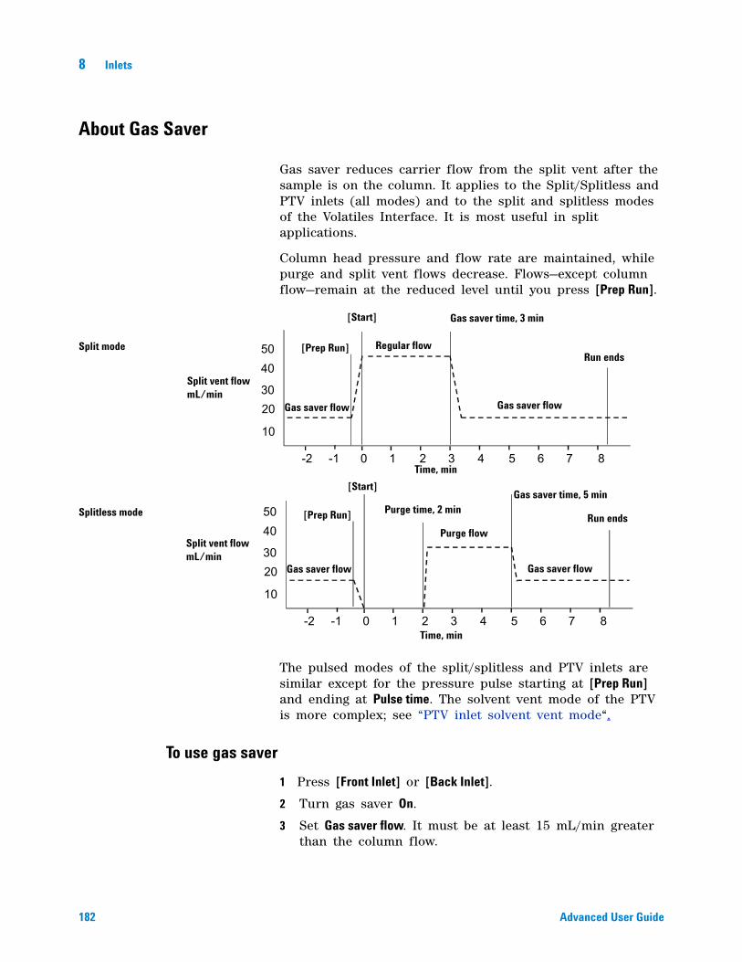
182 Advanced User Guide
8 Inlets
About Gas Saver
Gas saver reduces carrier flow from the split vent after the sample is on the column. It applies to the Split/Splitless and PTV inlets (all modes) and to the split and splitless modes of the Volatiles Interface. It is most useful in split applications.
Column head pressure and flow rate are maintained, while purge and split vent flows decrease. Flows—except column flow—remain at the reduced level until you press [Prep Run].
The pulsed modes of the split/splitless and PTV inlets are similar except for the pressure pulse starting at [Prep Run] and ending at Pulse time. The solvent vent mode of the PTV is more complex; see “PTV inlet solvent vent mode“.
To use gas saver
1 Press [Front Inlet] or [Back Inlet].
2 Turn gas saver On.
3 Set Gas saver flow. It must be at least 15 mL/min greater than the column flow.
0 1 2 3 4 5 6 7 8
10
2030
4050
-1-2
0 1 2 3 4 5 6 7 8
10
2030
4050
-1-2
Split mode
Splitless mode
Split vent flow mL/min
Split vent flow mL/min
Time, min
Time, min
Gas saver flow
Gas saver flow
Gas saver flow
Gas saver flow
Purge flow
Regular flow
[Prep Run]
[Prep Run]
[Start]
[Start]
Gas saver time, 3 min
Gas saver time, 5 min
Run ends
Run endsPurge time, 2 min

Inlets 8
Advanced User Guide 183
4 If in split mode, set Saver time after injection time. In all other modes, set after Purge time.
184 Advanced User Guide
8 Inlets
Pre Run and Prep Run
With some inlets and operating modes, certain instrument setpoints are different between runs than during an analysis. To restore the setpoints for injection, you must place the GC into the Pre Run state.
You must use the Pre Run state when:
• Using gas saver with any inlet.
• Using splitless mode with any inlet.
• Using a pressure pulse mode with any inlet.
• Using the solvent vent mode of the PTV inlet.
• Using the direct or splitless mode of the Volatiles Interface.
There are three ways to begin Pre Run—manually (press [Prep Run] before each run), automatically (for Agilent samplers), or using Auto Prep Run (for non- Agilent samplers). The three methods are discussed below.
During the Pre Run state:
• The Pre Run light blinks and Not Ready is on.
• Setpoints change to the correct values for injection.
• Inlet, detector, and oven equilibration times begin.
When all equilibration times expire, the Pre Run light is on steadily. When all criteria for a run are met, the Not Ready light turns off. The GC is now ready for sample injection.
The [Prep Run] key
Press [Prep Run] before you inject a sample manually. The GC enters the Pre Run state. When the Pre Run light is steady and the Not Ready light goes off, begin the analysis.
Agilent samplers
If you are using an Agilent automatic sampling system, the [Prep Run] function is automatic.
Start the sampler. It generates the [Prep Run] function, When all the setpoints are reached and the GC becomes Ready, sample injection begins.
Inlets 8
Advanced User Guide 185
Non-Agilent samplers
With most automatic injection systems, you do not need to use the [Prep Run] key. If your sampler or automation controller (for example, an integrator or workstation) does not support the [Prep Run] function, you must set the GC to Auto Prep Run.
Auto Prep Run
To set this parameter, usually for a non- Agilent integrator, workstation, or other controlling device:
1 Press [Config] to view a list of configurable parameters.
2 Scroll to Instrument and press [Enter].
3 Scroll to Auto prep run and press [On/Yes].
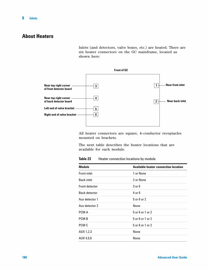
186 Advanced User Guide
8 Inlets
About Heaters
Inlets (and detectors, valve boxes, etc.) are heated. There are six heater connectors on the GC mainframe, located as shown here:
All heater connectors are square, 4- conductor receptacles mounted on brackets.
The next table describes the heater locations that are available for each module.
1
2
3
4
5
6
Front of GC
Near front inlet
Near back inlet
Near top right cornerof front detector board
Near top right cornerof back detector board
Left end of valve bracket
Right end of valve bracket
Table 23 Heater connection locations by module
Module Available heater connection location
Front inlet 1 or None
Back inlet 2 or None
Front detector 3 or 5
Back detector 4 or 6
Aux detector 1 5 or 6 or 2
Aux detector 2 None
PCM A 5 or 6 or 1 or 2
PCM B 5 or 6 or 1 or 2
PCM C 5 or 6 or 1 or 2
AUX 1,2,3 None
AUX 4,5,6 None
Inlets 8
Advanced User Guide 187
Front FPD uses heater connectors 3 and 5.
Back FPD uses heater connectors 4 and 6.
FPDs can be configured for one or two heater versions.
AUX 7,8,9 None
Valve box 5 or 6 or Both
Aux heater 1 5
Aux heater 2 6
Table 23 Heater connection locations by module (continued)
Module Available heater connection location
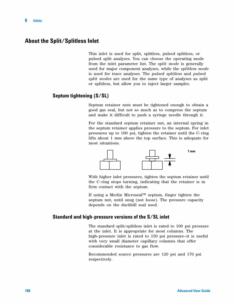
188 Advanced User Guide
8 Inlets
About the Split/Splitless Inlet
This inlet is used for split, splitless, pulsed splitless, or pulsed split analyses. You can choose the operating mode from the inlet parameter list. The split mode is generally used for major component analyses, while the splitless mode is used for trace analyses. The pulsed splitless and pulsed split modes are used for the same type of analyses as split or splitless, but allow you to inject larger samples.
Septum tightening (S/SL)
Septum retainer nuts must be tightened enough to obtain a good gas seal, but not so much as to compress the septum and make it difficult to push a syringe needle through it.
For the standard septum retainer nut, an internal spring in the septum retainer applies pressure to the septum. For inlet pressures up to 100 psi, tighten the retainer until the C- ring lifts about 1 mm above the top surface. This is adequate for most situations.
With higher inlet pressures, tighten the septum retainer until the C- ring stops turning, indicating that the retainer is in firm contact with the septum.
If using a Merlin Microseal™ septum, finger tighten the septum nut, until snug (not loose). The pressure capacity depends on the duckbill seal used.
Standard and high-pressure versions of the S/SL inlet
The standard split/splitless inlet is rated to 100 psi pressure at the inlet. It is appropriate for most columns. The high- pressure inlet is rated to 150 psi pressure—it is useful with very small diameter capillary columns that offer considerable resistance to gas flow.
Recommended source pressures are 120 psi and 170 psi respectively.
1 mm
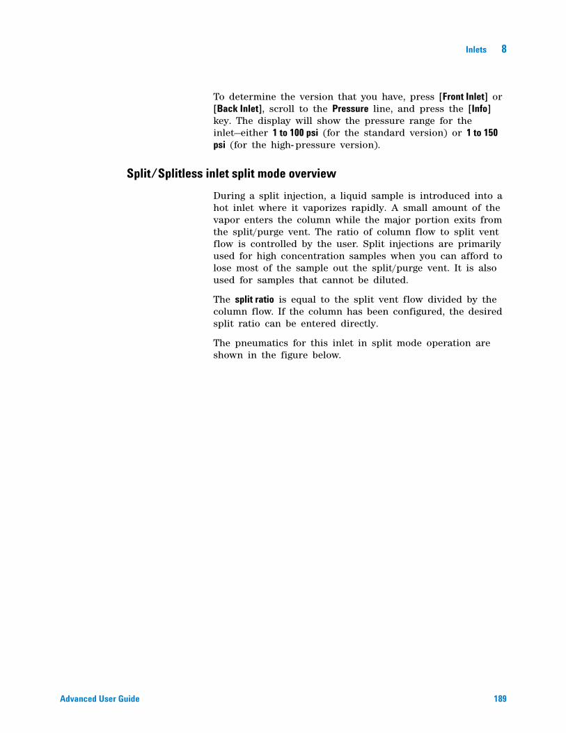
Inlets 8
Advanced User Guide 189
To determine the version that you have, press [Front Inlet] or [Back Inlet], scroll to the Pressure line, and press the [Info] key. The display will show the pressure range for the inlet—either 1 to 100 psi (for the standard version) or 1 to 150 psi (for the high- pressure version).
Split/Splitless inlet split mode overview
During a split injection, a liquid sample is introduced into a hot inlet where it vaporizes rapidly. A small amount of the vapor enters the column while the major portion exits from the split/purge vent. The ratio of column flow to split vent flow is controlled by the user. Split injections are primarily used for high concentration samples when you can afford to lose most of the sample out the split/purge vent. It is also used for samples that cannot be diluted.
The split ratio is equal to the split vent flow divided by the column flow. If the column has been configured, the desired split ratio can be entered directly.
The pneumatics for this inlet in split mode operation are shown in the figure below.
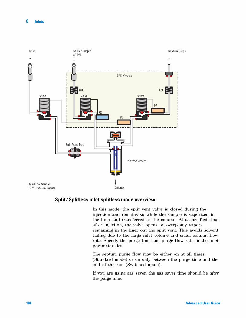
190 Advanced User Guide
8 Inlets
Split/Splitless inlet splitless mode overview
In this mode, the split vent valve is closed during the injection and remains so while the sample is vaporized in the liner and transferred to the column. At a specified time after injection, the valve opens to sweep any vapors remaining in the liner out the split vent. This avoids solvent tailing due to the large inlet volume and small column flow rate. Specify the purge time and purge flow rate in the inlet parameter list.
The septum purge flow may be either on at all times (Standard mode) or on only between the purge time and the end of the run (Switched mode).
If you are using gas saver, the gas saver time should be after the purge time.
Valve
Frit Frit
Valve
EPC Module
Valve
Split Vent Trap
Inlet Weldment
FS = Flow SensorPS = Pressure Sensor
FSPS
PS
Split Carrier Supply80 PSI
Septum Purge
Column
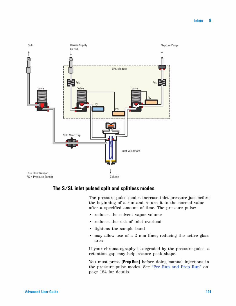
Inlets 8
Advanced User Guide 191
The S/SL inlet pulsed split and splitless modes
The pressure pulse modes increase inlet pressure just before the beginning of a run and return it to the normal value after a specified amount of time. The pressure pulse:
• reduces the solvent vapor volume
• reduces the risk of inlet overload
• tightens the sample band
• may allow use of a 2 mm liner, reducing the active glass area
If your chromatography is degraded by the pressure pulse, a retention gap may help restore peak shape.
You must press [Prep Run] before doing manual injections in the pressure pulse modes. See “Pre Run and Prep Run” on page 184 for details.
Valve
Frit Frit
Valve
EPC Module
Valve
Split Vent Trap
Inlet Weldment
FS = Flow SensorPS = Pressure Sensor
FSPS
PS
Split Carrier Supply80 PSI
Septum Purge
Column
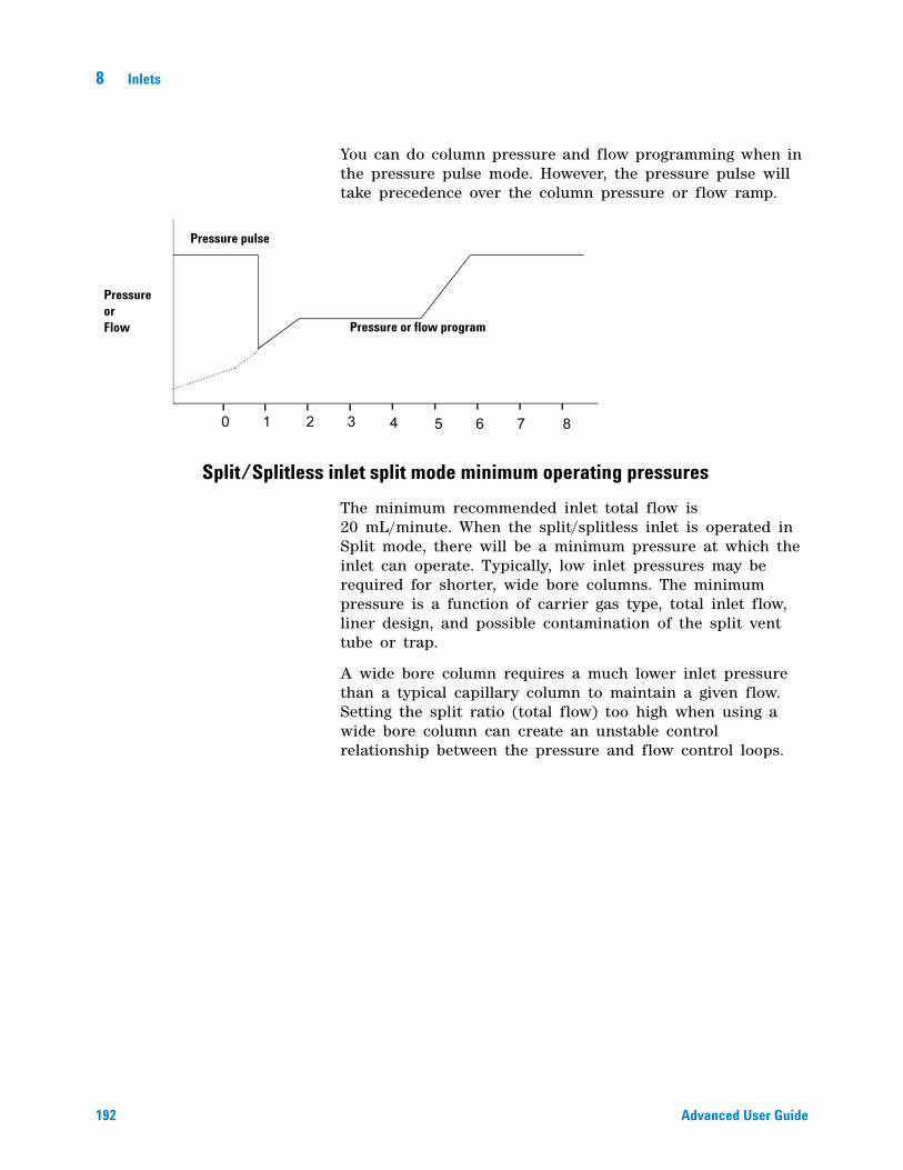
192 Advanced User Guide
8 Inlets
You can do column pressure and flow programming when in the pressure pulse mode. However, the pressure pulse will take precedence over the column pressure or flow ramp.
Split/Splitless inlet split mode minimum operating pressures
The minimum recommended inlet total flow is 20 mL/minute. When the split/splitless inlet is operated in Split mode, there will be a minimum pressure at which the inlet can operate. Typically, low inlet pressures may be required for shorter, wide bore columns. The minimum pressure is a function of carrier gas type, total inlet flow, liner design, and possible contamination of the split vent tube or trap.
A wide bore column requires a much lower inlet pressure than a typical capillary column to maintain a given flow. Setting the split ratio (total flow) too high when using a wide bore column can create an unstable control relationship between the pressure and flow control loops.
0 1 2 3 4 5 6 7 8
Pressure pulse
Pressure or flow program
Pressure or Flow
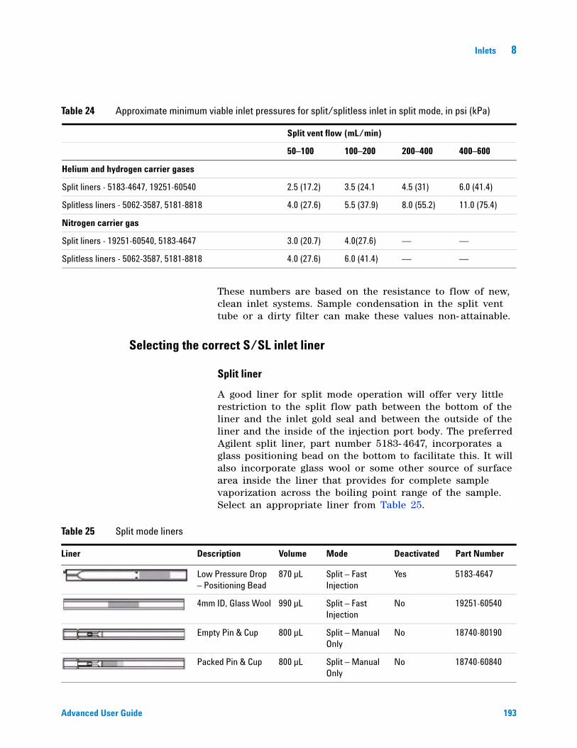
Inlets 8
Advanced User Guide 193
These numbers are based on the resistance to flow of new, clean inlet systems. Sample condensation in the split vent tube or a dirty filter can make these values non- attainable.
Selecting the correct S/SL inlet liner
Split liner
A good liner for split mode operation will offer very little restriction to the split flow path between the bottom of the liner and the inlet gold seal and between the outside of the liner and the inside of the injection port body. The preferred Agilent split liner, part number 5183- 4647, incorporates a glass positioning bead on the bottom to facilitate this. It will also incorporate glass wool or some other source of surface area inside the liner that provides for complete sample vaporization across the boiling point range of the sample. Select an appropriate liner from Table 25.
Table 24 Approximate minimum viable inlet pressures for split/splitless inlet in split mode, in psi (kPa)
Split vent flow (mL/min)
50–100 100–200 200–400 400–600
Helium and hydrogen carrier gases
Split liners - 5183-4647, 19251-60540 2.5 (17.2) 3.5 (24.1 4.5 (31) 6.0 (41.4)
Splitless liners - 5062-3587, 5181-8818 4.0 (27.6) 5.5 (37.9) 8.0 (55.2) 11.0 (75.4)
Nitrogen carrier gas
Split liners - 19251-60540, 5183-4647 3.0 (20.7) 4.0(27.6) — —
Splitless liners - 5062-3587, 5181-8818 4.0 (27.6) 6.0 (41.4) — —
Table 25 Split mode liners
Liner Description Volume Mode Deactivated Part Number
Low Pressure Drop – Positioning Bead
870 µL Split – Fast Injection
Yes 5183-4647
4mm ID, Glass Wool 990 µL Split – Fast Injection
No 19251-60540
Empty Pin & Cup 800 µL Split – Manual Only
No 18740-80190
Packed Pin & Cup 800 µL Split – Manual Only
No 18740-60840
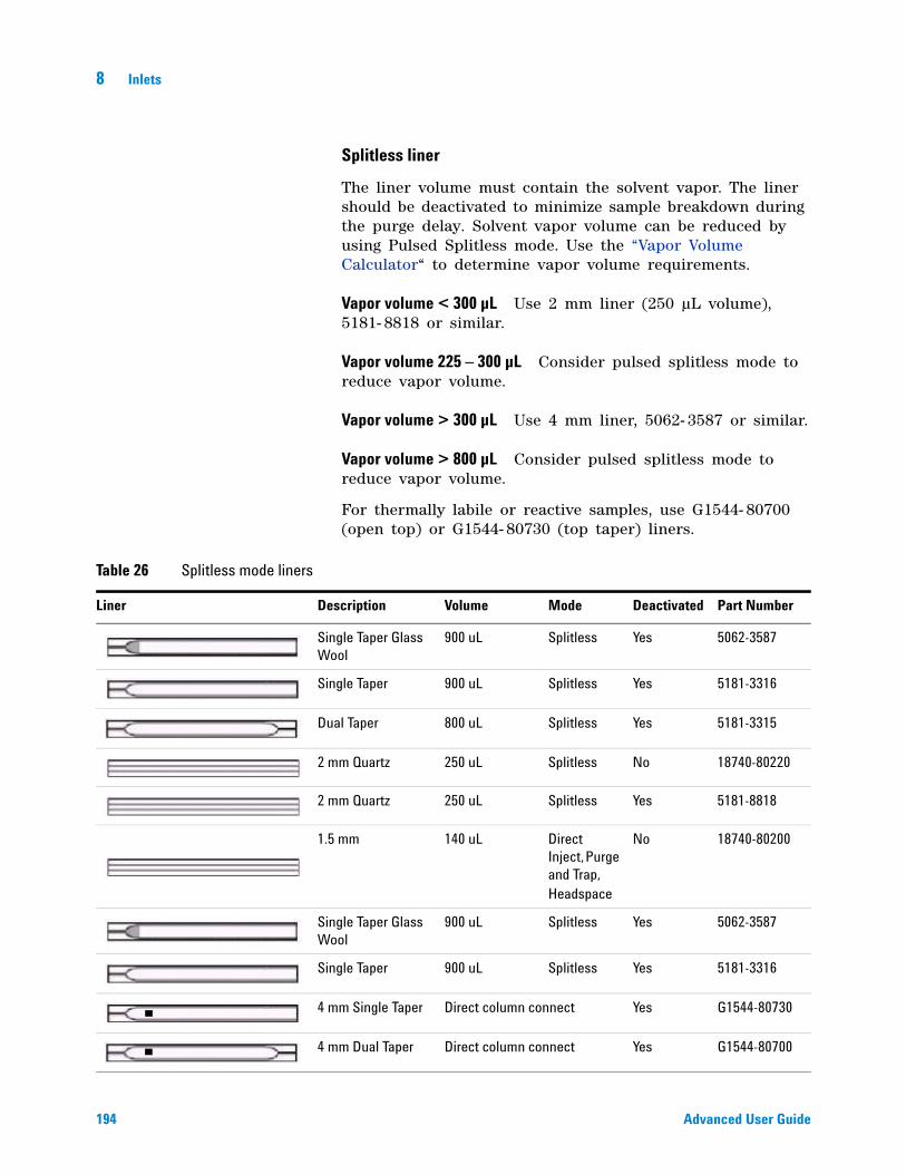
194 Advanced User Guide
8 Inlets
Splitless liner
The liner volume must contain the solvent vapor. The liner should be deactivated to minimize sample breakdown during the purge delay. Solvent vapor volume can be reduced by using Pulsed Splitless mode. Use the “Vapor Volume Calculator“ to determine vapor volume requirements.
Vapor volume < 300 µL Use 2 mm liner (250 µL volume), 5181- 8818 or similar.
Vapor volume 225 – 300 µL Consider pulsed splitless mode to reduce vapor volume.
Vapor volume > 300 µL Use 4 mm liner, 5062- 3587 or similar.
Vapor volume > 800 µL Consider pulsed splitless mode to reduce vapor volume.
For thermally labile or reactive samples, use G1544- 80700 (open top) or G1544- 80730 (top taper) liners.
Table 26 Splitless mode liners
Liner Description Volume Mode Deactivated Part Number
Single Taper Glass Wool
900 uL Splitless Yes 5062-3587
Single Taper 900 uL Splitless Yes 5181-3316
Dual Taper 800 uL Splitless Yes 5181-3315
2 mm Quartz 250 uL Splitless No 18740-80220
2 mm Quartz 250 uL Splitless Yes 5181-8818
1.5 mm 140 uL Direct Inject, Purge and Trap, Headspace
No 18740-80200
Single Taper Glass Wool
900 uL Splitless Yes 5062-3587
Single Taper 900 uL Splitless Yes 5181-3316
4 mm Single Taper Direct column connect Yes G1544-80730
4 mm Dual Taper Direct column connect Yes G1544-80700
Inlets 8
Advanced User Guide 195
Vapor Volume Calculator
Agilent provides a Vapor Volume Calculator to help you determine if a liner is suitable for a method. To use the calculator install the Agilent Instrument utility provided with the GC. The calculator is also provided with the Agilent Instrument Utilities software.
Setting parameters for the S/SL split mode
Mode The current operating mode—split
Temperature Actual and setpoint inlet temperatures
Pressure Actual and setpoint inlet pressure
Split ratio The ratio of split vent flow to column flow. Column flow is set at the Column parameter list. This line appears only if your columns in the flow path are defined.
Split flow Flow, in mL/min, from the split vent. This line appears only if your columns in the flow path are defined.
Total flow This is the total flow into the inlet, which is the sum of the split vent flow, column flow, and septum purge flow. When you change the total flow, the split ratio and split vent flow change while the column flow and pressure remain the same.
Septum Purge Flow, in mL/min, through the septum purge line. Recommended range is 1 to 5 mL/min.
If all columns in the flow path are defined
1 Press [Front Inlet] or [Back Inlet].
2 Scroll to Mode: and press [Mode/Type]. Select Split.
3 Set the inlet temperature.
4 If you want a specific split ratio, scroll to Split ratio and enter that number. Split flow will be calculated for you.
5 If you want a specific split flow, scroll to Split flow and enter that number. Split ratio will be calculated for you.
6 If desired, turn on Gas saver. Set Saver time after the injection time. Press [Prep Run] (see “Pre Run and Prep Run” on page 184) before manually injecting the sample.
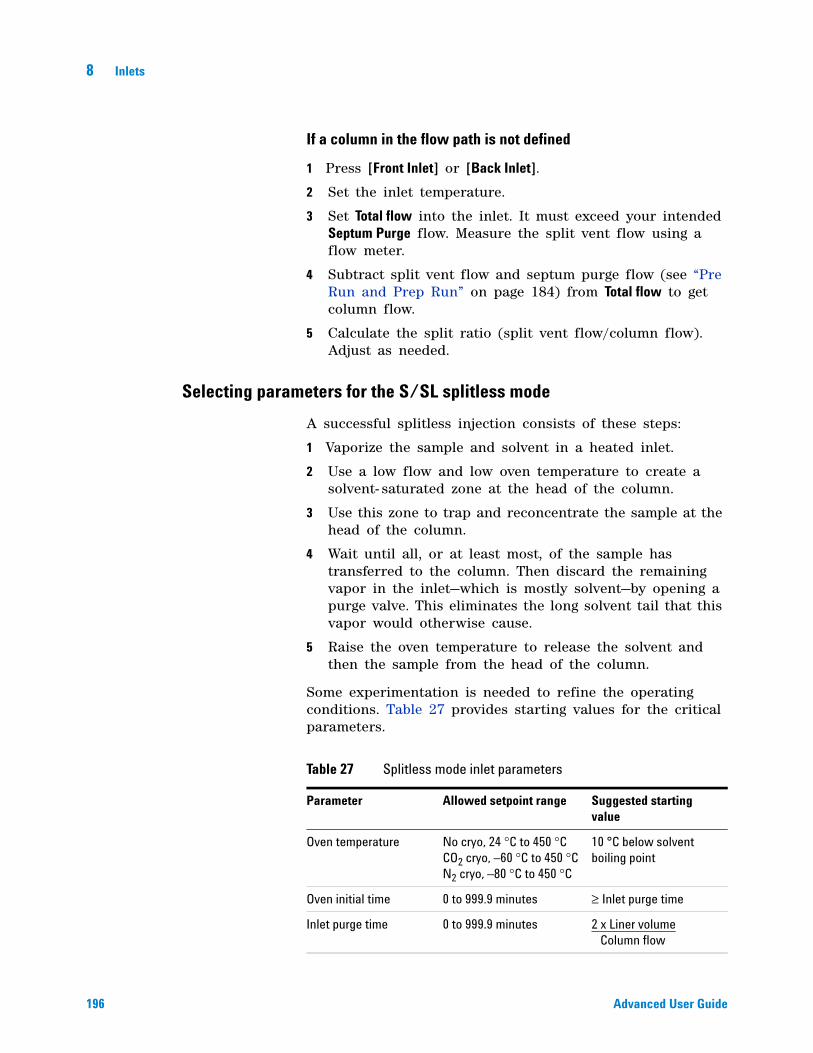
196 Advanced User Guide
8 Inlets
If a column in the flow path is not defined
1 Press [Front Inlet] or [Back Inlet].
2 Set the inlet temperature.
3 Set Total flow into the inlet. It must exceed your intended Septum Purge flow. Measure the split vent flow using a flow meter.
4 Subtract split vent flow and septum purge flow (see “Pre Run and Prep Run” on page 184) from Total flow to get column flow.
5 Calculate the split ratio (split vent flow/column flow). Adjust as needed.
Selecting parameters for the S/SL splitless mode
A successful splitless injection consists of these steps:
1 Vaporize the sample and solvent in a heated inlet.
2 Use a low flow and low oven temperature to create a solvent- saturated zone at the head of the column.
3 Use this zone to trap and reconcentrate the sample at the head of the column.
4 Wait until all, or at least most, of the sample has transferred to the column. Then discard the remaining vapor in the inlet—which is mostly solvent—by opening a purge valve. This eliminates the long solvent tail that this vapor would otherwise cause.
5 Raise the oven temperature to release the solvent and then the sample from the head of the column.
Some experimentation is needed to refine the operating conditions. Table 27 provides starting values for the critical parameters.
Table 27 Splitless mode inlet parameters
Parameter Allowed setpoint range Suggested starting value
Oven temperature No cryo, 24 °C to 450 °C CO2 cryo, –60 °C to 450 °C N2 cryo, –80 °C to 450 °C
10 °C below solvent boiling point
Oven initial time 0 to 999.9 minutes ≥ Inlet purge time
Inlet purge time 0 to 999.9 minutes 2 x Liner volume Column flow
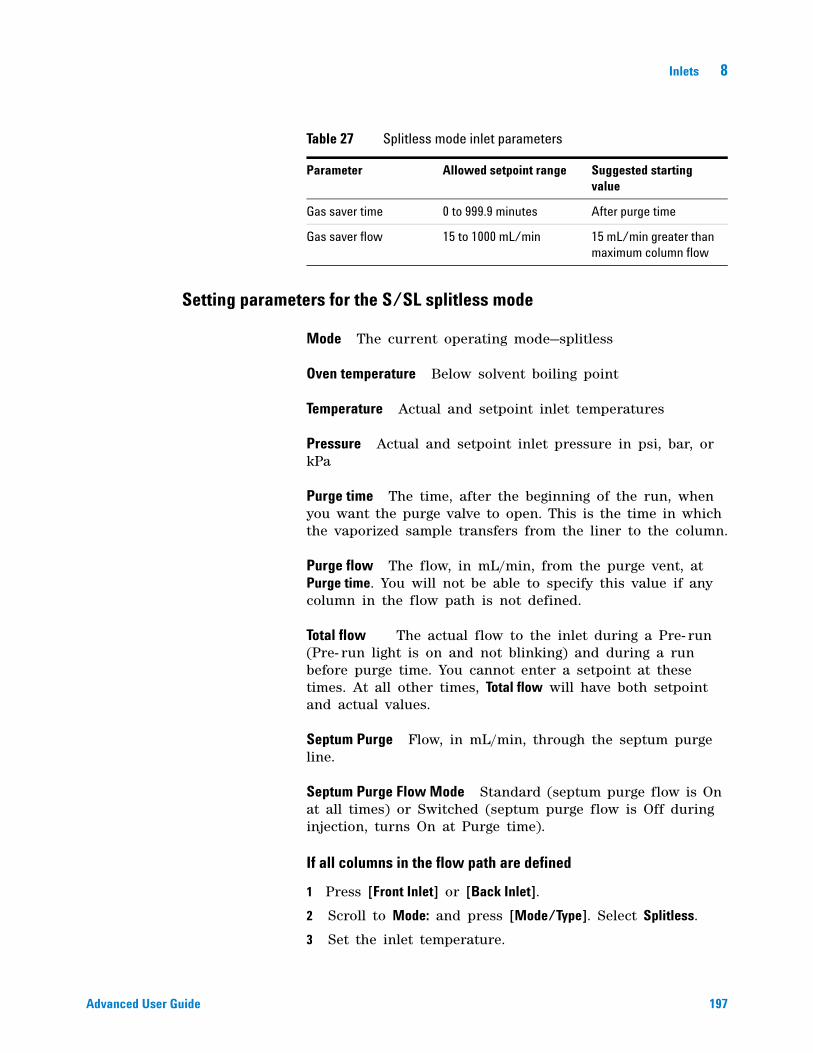
Inlets 8
Advanced User Guide 197
Setting parameters for the S/SL splitless mode
Mode The current operating mode—splitless
Oven temperature Below solvent boiling point
Temperature Actual and setpoint inlet temperatures
Pressure Actual and setpoint inlet pressure in psi, bar, or kPa
Purge time The time, after the beginning of the run, when you want the purge valve to open. This is the time in which the vaporized sample transfers from the liner to the column.
Purge flow The flow, in mL/min, from the purge vent, at Purge time. You will not be able to specify this value if any column in the flow path is not defined.
Total flow The actual flow to the inlet during a Pre- run (Pre- run light is on and not blinking) and during a run before purge time. You cannot enter a setpoint at these times. At all other times, Total flow will have both setpoint and actual values.
Septum Purge Flow, in mL/min, through the septum purge line.
Septum Purge Flow Mode Standard (septum purge flow is On at all times) or Switched (septum purge flow is Off during injection, turns On at Purge time).
If all columns in the flow path are defined
1 Press [Front Inlet] or [Back Inlet].
2 Scroll to Mode: and press [Mode/Type]. Select Splitless.
3 Set the inlet temperature.
Gas saver time 0 to 999.9 minutes After purge time
Gas saver flow 15 to 1000 mL/min 15 mL/min greater than maximum column flow
Table 27 Splitless mode inlet parameters
Parameter Allowed setpoint range Suggested starting value
198 Advanced User Guide
8 Inlets
4 Enter a Purge time and a Purge flow.
5 If desired, turn on Gas saver. Make certain the time is set after the Purge time.
6 Press [Prep Run] (see “Pre Run and Prep Run” on page 184) before manually injecting a sample (this is automatic for Agilent ALS).
If a column in the flow path is not defined
1 Press [Front Inlet] or [Back Inlet].
2 Scroll to Mode: and press [Mode/Type]. Select Splitless.
3 Set the inlet temperature.
4 Enter a Purge time.
5 Set your Total flow greater than the sum of column flow plus the septum purge flow—see “Pre Run and Prep Run” on page 184—to guarantee adequate column flow.
6 Press [Prep Run] (see “Pre Run and Prep Run” on page 184) before manually injecting a sample.
Setting parameters for the S/SL pulsed modes
The pulsed mode parameters are the same as the non- pulsed parameters, but with two additional values.
Pulsed pressure The inlet pressure you want at the start of the run. The pressure rises to this value when [Prep Run] is pressed and remains constant until Pulse time elapses, when it returns to Pressure.
Pulse time This is the time after the start of the run when the inlet pressure returns to Pressure.
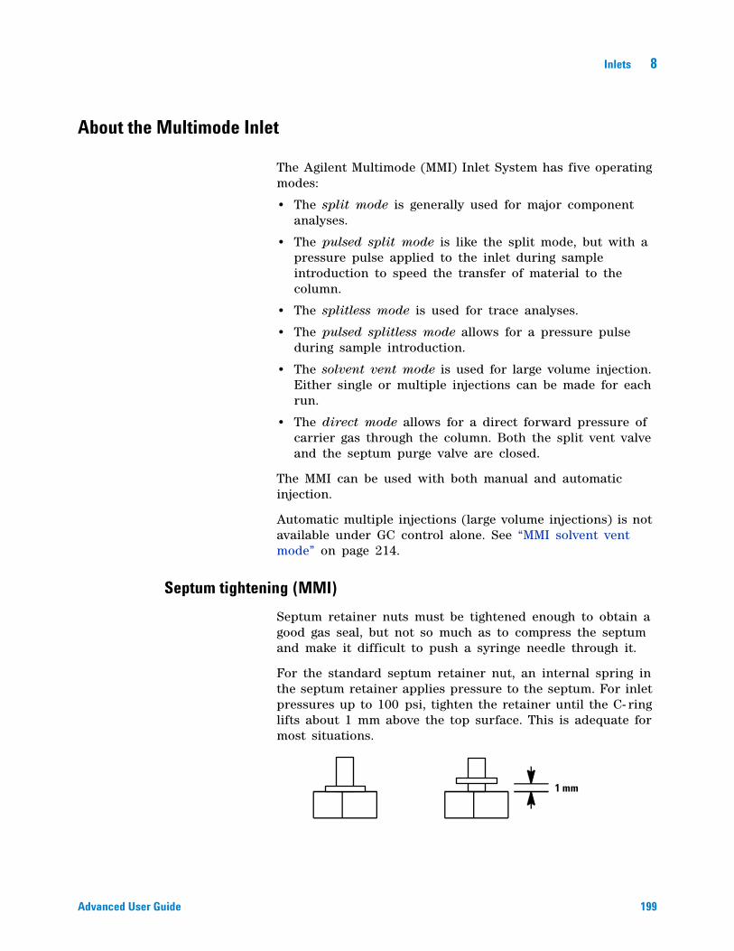
Inlets 8
Advanced User Guide 199
About the Multimode Inlet
The Agilent Multimode (MMI) Inlet System has five operating modes:
• The split mode is generally used for major component analyses.
• The pulsed split mode is like the split mode, but with a pressure pulse applied to the inlet during sample introduction to speed the transfer of material to the column.
• The splitless mode is used for trace analyses.
• The pulsed splitless mode allows for a pressure pulse during sample introduction.
• The solvent vent mode is used for large volume injection. Either single or multiple injections can be made for each run.
• The direct mode allows for a direct forward pressure of carrier gas through the column. Both the split vent valve and the septum purge valve are closed.
The MMI can be used with both manual and automatic injection.
Automatic multiple injections (large volume injections) is not available under GC control alone. See “MMI solvent vent mode” on page 214.
Septum tightening (MMI)
Septum retainer nuts must be tightened enough to obtain a good gas seal, but not so much as to compress the septum and make it difficult to push a syringe needle through it.
For the standard septum retainer nut, an internal spring in the septum retainer applies pressure to the septum. For inlet pressures up to 100 psi, tighten the retainer until the C- ring lifts about 1 mm above the top surface. This is adequate for most situations.
1 mm
200 Advanced User Guide
8 Inlets
With higher inlet pressures, tighten the septum retainer until the C- ring stops turning, indicating that the retainer is in firm contact with the septum.
If using a Merlin Microseal™ septum, finger tighten the septum nut, until snug (not loose). The pressure capacity depends on the duckbill seal used.
Heating the MMI
Programming the MMI temperature is similar to programming the column oven. Access the inlet parameters by pressing [Front Inlet] or [Back Inlet]. Temperature can be programmed with an initial temperature and up to 10 ramps (rates and plateaus). See “MMI split and pulsed split modes“ for details.
At the end of the run and during post- run, the MMI is held at its final temperature. This permits backflushing without contaminating the inlet.
Additional temperature ramps
For most purposes, the MMI is designed to hold the sample in the inlet liner until the entire sample—there could be several injections—has been injected. Then the MMI is heated rapidly to transfer the sample to the column. This can be accomplished with an initial hold, a single ramp, and a hold at the end to complete sample transfer.
Additional ramps are available and have several possible uses:
• The inlet can be heated to a high temperature to thermally clean the liner for the next run.
• The inlet can be programmed downward—just set the Final temp below the previous temperature—to reduce thermal stress on the inlet.
• Downward programming can be used to prepare the inlet for the next run. This can reduce cycle time for greater sample throughput.
Cooling the MMI
If using cryogen to cool the MMI inlet, both liquid carbon dioxide (LCO2) and liquid nitrogen (LN2) are supported. In addition to the cryogenic coolants, the MMI supports compressed air cooling on both the LCO2 and LN2 cooling options for legacy applications.
Inlets 8
Advanced User Guide 201
If using cryo as the coolant when configuring the initial inlet setpoint, set the Use cryo temperature equal to or higher than the inlet setpoint to cool the inlet and hold the setpoint until the inlet temperature program exceeds the Use cryo temperature. If the Use cryo temperature is less than the inlet setpoint, cryogen will cool the inlet to the initial setpoint and turn off.
If using compressed air as the coolant when configuring the initial inlet setpoint, Use cryo temperature behaves differently when in Compressed air mode than it does when in N2 cryo or CO2 cryo mode. In Compressed air mode, the air coolant is used to cool the inlet regardless of the Use cryo temperature setpoint during the cooling cycle. If the inlet reaches setpoint, the air coolant is turned off and stays off. If the oven temperature is high enough or the inlet was very hot previously, it is possible that the inlet temperature will rise and the GC will go not ready. For this reason, it is better to set the instrument cooling configuration as N2 cryo or CO2 cryo when using compressed air as the coolant. When using compressed air, the LN2 hardware cools the inlet faster than the LCO2 hardware. Never use LCO2 or LN2 when the instrument is configured in Compressed air mode.
If cryo is turned on, and if the inlet is cooled during a run, cryogen is used to achieve the setpoint. This may have a negative impact on the chromatographic performance of the oven and cause distorted peaks.
When a method ends, the cooling setpoint returns to the initial state of the method, unless you load another method. To conserve coolant when the GC is idle, load a method that does not use a cooling configuration.
See “To configure the MMI coolant” on page 32.
MMI split mode minimum operating pressures
The minimum recommended inlet total flow is 20 mL/minute. When the inlet is operated in a Split mode, there will be a minimum pressure at which the inlet can operate. Typically, low inlet pressures may be required for shorter, wide bore columns. The minimum pressure is a function of carrier gas type, total inlet flow, liner design, and possible contamination of the split vent tube or trap.

202 Advanced User Guide
8 Inlets
A wide bore column requires a much lower inlet pressure than a typical capillary column to maintain a given flow. Setting the split ratio (total flow) too high when using a wide bore column can create an unstable control relationship between the pressure and flow control loops.
These numbers are based on the resistance to flow of new, clean inlet systems. Sample condensation in the split vent tube or a dirty filter can make these values non- attainable.
Selecting the correct MMI liner
Split liner
A good liner for split mode operation will offer very little restriction to the split flow path between the bottom of the liner and the inlet body and between the outside of the liner and the inside of the inlet body. The preferred Agilent split liner, part number 5183- 4647, incorporates a glass positioning bead on the bottom to facilitate this. It will also incorporate glass wool or some other source of surface area inside the liner that provides for complete sample vaporization across the boiling point range of the sample. Select an appropriate liner from Table 29.
Table 28 Approximate minimum viable inlet pressures for MMI in split mode, in psi (kPa)
Split vent flow (mL/min)
50–100 100–200 200–400 400–600
Helium and hydrogen carrier gases
Split liners - 5183-4647, 19251-60540 2.5 (17.2) 3.5 (24.1 4.5 (31) 6.0 (41.4)
Splitless liners - 5062-3587, 5181-8818 4.0 (27.6) 5.5 (37.9) 8.0 (55.2) 11.0 (75.4)
Nitrogen carrier gas
Split liners - 19251-60540, 5183-4647 3.0 (20.7) 4.0(27.6) — —
Splitless liners - 5062-3587, 5181-8818 4.0 (27.6) 6.0 (41.4) — —
Table 29 Split mode liners
Liner Description Volume Mode Deactivated Part Number
Low Pressure Drop – Positioning Bead
870 µL Split – Fast Injection
Yes 5183-4647
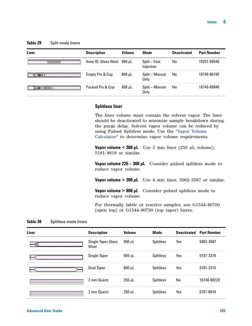
Inlets 8
Advanced User Guide 203
Splitless liner
The liner volume must contain the solvent vapor. The liner should be deactivated to minimize sample breakdown during the purge delay. Solvent vapor volume can be reduced by using Pulsed Splitless mode. Use the “Vapor Volume Calculator“ to determine vapor volume requirements.
Vapor volume < 300 µL Use 2 mm liner (250 µL volume), 5181- 8818 or similar.
Vapor volume 225 – 300 µL Consider pulsed splitless mode to reduce vapor volume.
Vapor volume > 300 µL Use 4 mm liner, 5062- 3587 or similar.
Vapor volume > 800 µL Consider pulsed splitless mode to reduce vapor volume.
For thermally labile or reactive samples, use G1544- 80700 (open top) or G1544- 80730 (top taper) liners.
4mm ID, Glass Wool 990 µL Split – Fast Injection
No 19251-60540
Empty Pin & Cup 800 µL Split – Manual Only
No 18740-80190
Packed Pin & Cup 800 µL Split – Manual Only
No 18740-60840
Table 29 Split mode liners
Liner Description Volume Mode Deactivated Part Number
Table 30 Splitless mode liners
Liner Description Volume Mode Deactivated Part Number
Single Taper Glass Wool
900 uL Splitless Yes 5062-3587
Single Taper 900 uL Splitless Yes 5181-3316
Dual Taper 800 uL Splitless Yes 5181-3315
2 mm Quartz 250 uL Splitless No 18740-80220
2 mm Quartz 250 uL Splitless Yes 5181-8818
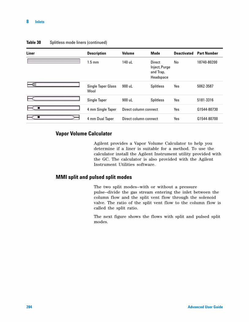
204 Advanced User Guide
8 Inlets
Vapor Volume Calculator
Agilent provides a Vapor Volume Calculator to help you determine if a liner is suitable for a method. To use the calculator install the Agilent Instrument utility provided with the GC. The calculator is also provided with the Agilent Instrument Utilities software.
MMI split and pulsed split modes
The two split modes—with or without a pressure pulse—divide the gas stream entering the inlet between the column flow and the split vent flow through the solenoid valve. The ratio of the split vent flow to the column flow is called the split ratio.
The next figure shows the flows with split and pulsed split modes.
1.5 mm 140 uL Direct Inject, Purge and Trap, Headspace
No 18740-80200
Single Taper Glass Wool
900 uL Splitless Yes 5062-3587
Single Taper 900 uL Splitless Yes 5181-3316
4 mm Single Taper Direct column connect Yes G1544-80730
4 mm Dual Taper Direct column connect Yes G1544-80700
Table 30 Splitless mode liners (continued)
Liner Description Volume Mode Deactivated Part Number
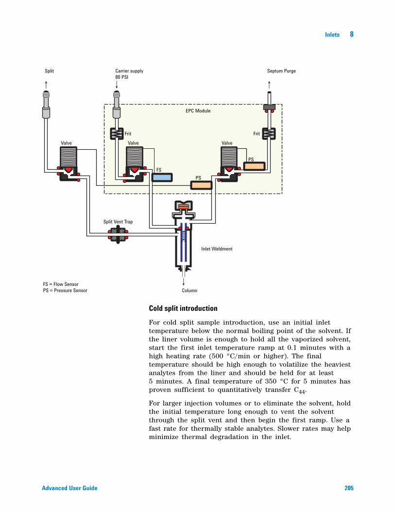
Inlets 8
Advanced User Guide 205
Cold split introduction
For cold split sample introduction, use an initial inlet temperature below the normal boiling point of the solvent. If the liner volume is enough to hold all the vaporized solvent, start the first inlet temperature ramp at 0.1 minutes with a high heating rate (500 °C/min or higher). The final temperature should be high enough to volatilize the heaviest analytes from the liner and should be held for at least 5 minutes. A final temperature of 350 °C for 5 minutes has proven sufficient to quantitatively transfer C44.
For larger injection volumes or to eliminate the solvent, hold the initial temperature long enough to vent the solvent through the split vent and then begin the first ramp. Use a fast rate for thermally stable analytes. Slower rates may help minimize thermal degradation in the inlet.
Split Carrier supply80 PSI
Septum Purge
Valve
Frit
EPC Module
PS
Inlet Weldment
Column
Split Vent Trap
FS = Flow SensorPS = Pressure Sensor
Valve Valve
Frit
PSFS
206 Advanced User Guide
8 Inlets
A single temperature ramp is enough for the injection process. The remaining ramps may be used to clean the liner or to reduce the inlet temperature in preparation for the next injection.
Hot split introduction
For hot split introduction, set an initial temperature high enough to volatilize the analytes. No additional thermal parameters are required as the inlet will maintain the setpoint throughout the run.
Setting parameters for split mode operation
Mode: The current operating mode—split or pulsed split
Temperature Actual and setpoint inlet temperatures.
Initial temperature Starting temperature for the inlet.
Initial time Hold time at the inlet initial temperature.
Rate # Temperature program rates for inlet thermal ramps.
Final temp # Final inlet temperature for ramp 1- 10.
Final time # Hold time at Final temp 1- 10.
Pressure Actual and setpoint inlet pressure. Controls capillary column flow and linear velocity.
Split ratio The ratio of split flow to column flow. Column flow is set in the column parameter list. This line does not appear if a column in the flow path is not defined.
Split flow Flow, in mL/min, from the split/purge vent. This line does not appear if a column in the flow path is not defined.
Total flow These are the actual and setpoint values of the total flow into the inlet, which is the sum of the split flow, column flow, and septum purge flow. When you change the total flow, the split ratio and split flow change while the column flow and pressure remain the same.
Septum Purge Flow through the septum purge vent.
Gas saver On to reduce split vent flow at Saver time.
Inlets 8
Advanced User Guide 207
Saver flow Reduced split vent flow, at least 15 mL/min.
Saver time Time when flow is reduced to save gas.
If all columns in the flow path are defined
1 Press [Front Inlet].
2 Scroll to Mode: and press [Mode/Type]. Select Split or Pulsed split.
3 Set the inlet temperature (Initial temperature) and any desired ramps.
4 If you want a specific split ratio, scroll to Split ratio and enter that number. The split flow will be calculated and set for you.
5 If you want a specific split flow, scroll to Split flow and enter that number. The split ratio will be calculated and displayed for you.
6 If you selected Pulsed split, enter values for Pulsed pressure (pressure at injection) and Pulse time (minutes after injection to return to normal pressure).
7 If desired, turn on Gas saver. Set the Saver time after the injection time.
8 Press [Prep Run] before manually injecting the sample if the Gas Saver is on (see “Pre Run and Prep Run” on page 184 for details.).
If a column in the flow path is not defined
1 Press [Front Inlet].
2 Set the inlet temperature (Initial temperature) and any desired ramps.
3 Set other parameters as described for a defined column.
4 Set Total flow into the inlet. Measure flows out of the split vent and septum purge vent using a flow meter.
5 Subtract the septum purge flow and split vent flow from Total flow to get column flow.
6 Calculate the split ratio (split vent flow/column flow). Adjust as needed
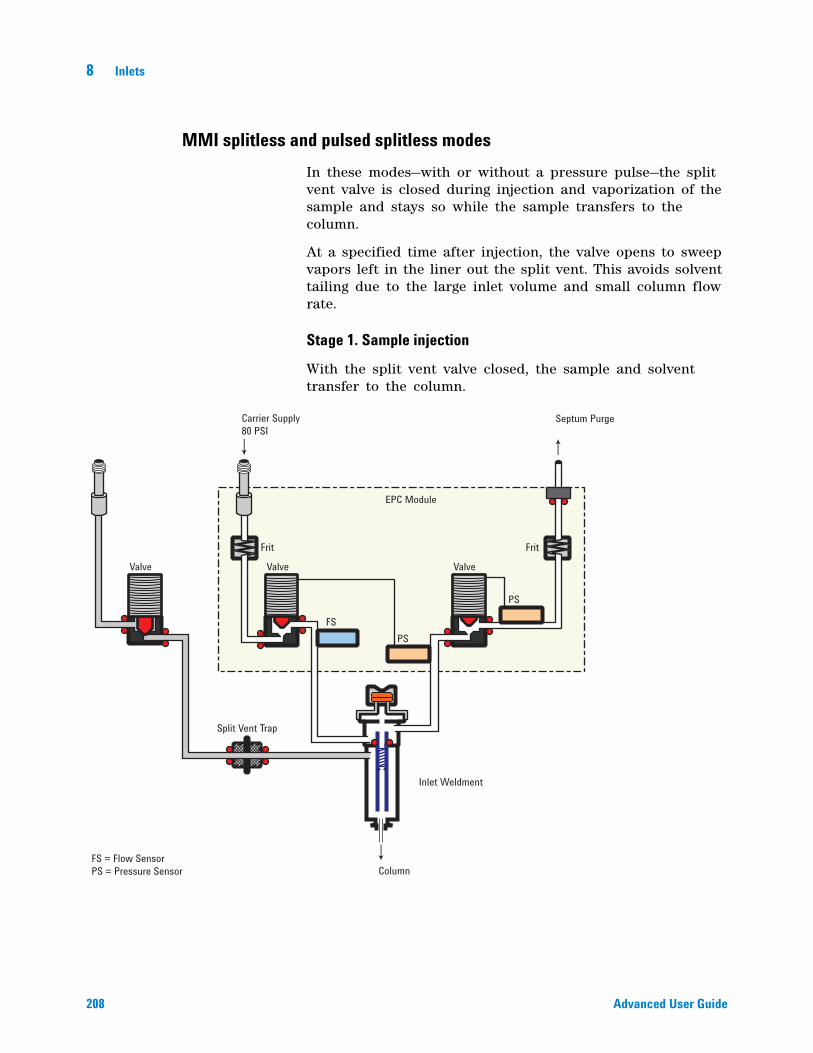
208 Advanced User Guide
8 Inlets
MMI splitless and pulsed splitless modes
In these modes—with or without a pressure pulse—the split vent valve is closed during injection and vaporization of the sample and stays so while the sample transfers to the column.
At a specified time after injection, the valve opens to sweep vapors left in the liner out the split vent. This avoids solvent tailing due to the large inlet volume and small column flow rate.
Stage 1. Sample injection
With the split vent valve closed, the sample and solvent transfer to the column.
Valve
Frit Frit
Valve
EPC Module
Valve
Split Vent Trap
Inlet Weldment
FS = Flow SensorPS = Pressure Sensor
FSPS
PS
Carrier Supply80 PSI
Septum Purge
Column
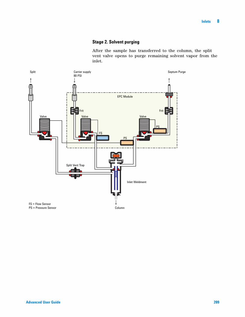
Inlets 8
Advanced User Guide 209
Stage 2. Solvent purging
After the sample has transferred to the column, the split vent valve opens to purge remaining solvent vapor from the inlet.
Split Carrier supply80 PSI
Septum Purge
Valve
Frit
EPC Module
PS
Inlet Weldment
Column
Split Vent Trap
FS = Flow SensorPS = Pressure Sensor
Valve Valve
Frit
PSFS
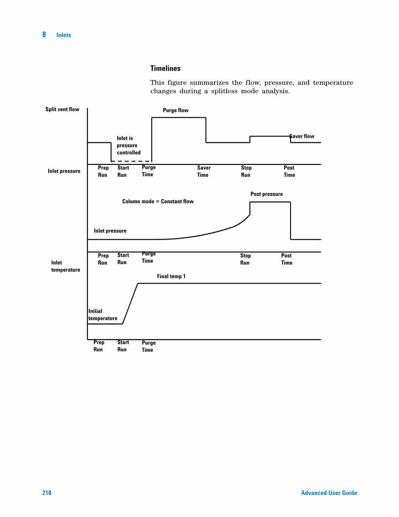
210 Advanced User Guide
8 Inlets
Timelines
This figure summarizes the flow, pressure, and temperature changes during a splitless mode analysis.
Split vent flow Purge flow
Saver flow
Inlet pressure
Inlet is pressure controlled
Post pressure
Inlet pressure
Inlet temperature
Final temp 1
Initial temperature
Prep Run
Start Run
Purge Time
Saver Time
Stop Run
Post Time
Post Time
Stop Run
Purge Time
Purge Time
Prep Run
Prep Run
Start Run
Start Run
Column mode = Constant flow
Inlets 8
Advanced User Guide 211
Cold splitless introduction
For cold splitless introduction, use an initial inlet temperature below the normal boiling point of the solvent. For most solvents, starting the first inlet temperature ramp at 0.1 minutes provides good transfer and reproducibility. A program rate of 500 °C/min or higher is appropriate for thermally stable analytes. A final temperature of 350 °C, held for 5 minutes, has quantitatively transferred up to C44 alkane.
A main advantage of temperature programmability is that the inlet can be heated gently to transfer delicate analytes. If the oven temperature is initially low enough to refocus the analytes on the column, the inlet heating rate can be made slower (e.g., 120 °C/min). This reduces thermal degradation from the inlet and can improve peak shape and quantitation.
For most applications of cold splitless, a single temperature ramp is enough. The remaining ramps can be used to clean the liner or to decrease the inlet temperature to prepare for the next injection.
Hot splitless introduction
For hot splitless introduction, select an initial temperature high enough to volatilize the analytes. No additional temperature parameters are required as the inlet will maintain the setpoint throughout the run.
Starting values
A successful splitless injection consists of these steps:
1 Inject the sample and temperature program the inlet to vaporize it.
2 Use a low column flow and low oven temperature to create a solvent- saturated zone at the head of the column.
3 Use this zone to trap and reconcentrate the sample at the head of the column.
4 Wait until all, or at least most, of the sample has transferred to the column. Then discard the remaining vapor in the inlet—which is mostly solvent—by opening a purge valve. This eliminates the long solvent tail that this vapor would otherwise cause.
5 Raise the oven temperature to analyze the sample.
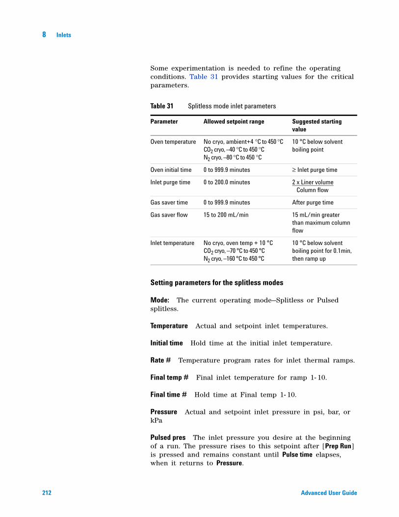
212 Advanced User Guide
8 Inlets
Some experimentation is needed to refine the operating conditions. Table 31 provides starting values for the critical parameters.
Setting parameters for the splitless modes
Mode: The current operating mode—Splitless or Pulsed splitless.
Temperature Actual and setpoint inlet temperatures.
Initial time Hold time at the initial inlet temperature.
Rate # Temperature program rates for inlet thermal ramps.
Final temp # Final inlet temperature for ramp 1- 10.
Final time # Hold time at Final temp 1- 10.
Pressure Actual and setpoint inlet pressure in psi, bar, or kPa
Pulsed pres The inlet pressure you desire at the beginning of a run. The pressure rises to this setpoint after [Prep Run] is pressed and remains constant until Pulse time elapses, when it returns to Pressure.
Table 31 Splitless mode inlet parameters
Parameter Allowed setpoint range Suggested starting value
Oven temperature No cryo, ambient+4 °C to 450 °C CO2 cryo, –40 °C to 450 °C N2 cryo, –80 °C to 450 °C
10 °C below solvent boiling point
Oven initial time 0 to 999.9 minutes ≥ Inlet purge time
Inlet purge time 0 to 200.0 minutes 2 x Liner volume Column flow
Gas saver time 0 to 999.9 minutes After purge time
Gas saver flow 15 to 200 mL/min 15 mL/min greater than maximum column flow
Inlet temperature No cryo, oven temp + 10 °C CO2 cryo, –70 °C to 450 °C N2 cryo, –160 °C to 450 °C
10 °C below solvent boiling point for 0.1min, then ramp up
Inlets 8
Advanced User Guide 213
Pulse time Pressure returns to its normal setpoint at this time.
Purge time The time, after the beginning of the run, when you want the split vent valve to open.
Purge flow The flow, in mL/min, from the split vent, at Purge time. You will not be able to specify this value if operating with your column not defined.
Total flow The Total flow line displays the actual flow to the inlet during a Pre- run (Pre- run light is on and not blinking) and during a run before purge time. You cannot enter a setpoint at these times. At all other times, Total flow will have both setpoint and actual values.
Septum purge Flow through the septum purge vent
Gas saver On to reduce split vent flow at Saver time
Server flow Reduced split vent flow, at least 15 mL/min
Server time Time when flow is reduced to save gas
If the column is defined
1 Press [Front Inlet].
2 Scroll to Mode: and press [Mode/Type]. Select Splitless or Pulsed splitless.
3 Set the inlet temperature and any desired ramps.
4 Enter a Purge time and a Purge flow.
5 If desired, turn Gas saver on. Make certain the time is set after the Purge time.
6 Press [Prep Run] (see “Pre Run and Prep Run” on page 184) before manually injecting a sample. This is automatic if an Agilent sampler is used.
If the column is not defined
1 Press [Front Inlet].
2 Scroll to Mode: and press [Mode/Type]. Select Splitless or Pulsed splitless.
3 Set the inlet temperature and any desired ramps.
4 Enter a Purge flow.
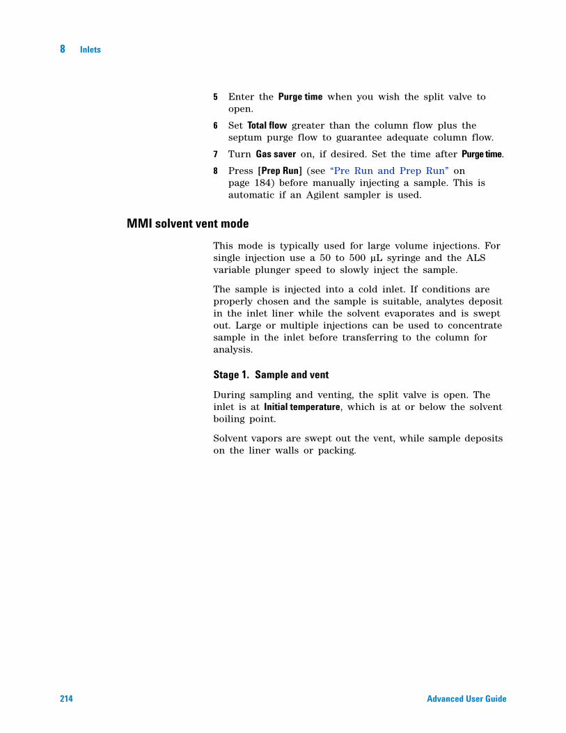
214 Advanced User Guide
8 Inlets
5 Enter the Purge time when you wish the split valve to open.
6 Set Total flow greater than the column flow plus the septum purge flow to guarantee adequate column flow.
7 Turn Gas saver on, if desired. Set the time after Purge time.
8 Press [Prep Run] (see “Pre Run and Prep Run” on page 184) before manually injecting a sample. This is automatic if an Agilent sampler is used.
MMI solvent vent mode
This mode is typically used for large volume injections. For single injection use a 50 to 500 µL syringe and the ALS variable plunger speed to slowly inject the sample.
The sample is injected into a cold inlet. If conditions are properly chosen and the sample is suitable, analytes deposit in the inlet liner while the solvent evaporates and is swept out. Large or multiple injections can be used to concentrate sample in the inlet before transferring to the column for analysis.
Stage 1. Sample and vent
During sampling and venting, the split valve is open. The inlet is at Initial temperature, which is at or below the solvent boiling point.
Solvent vapors are swept out the vent, while sample deposits on the liner walls or packing.
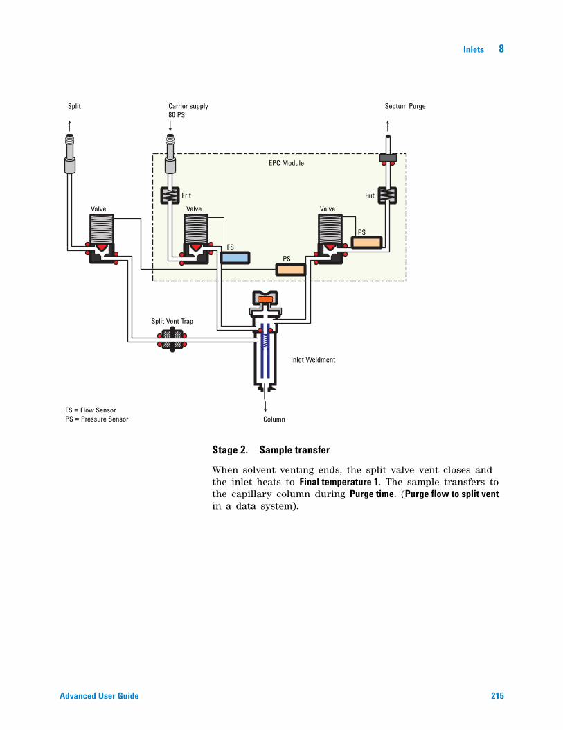
Inlets 8
Advanced User Guide 215
Stage 2. Sample transfer
When solvent venting ends, the split valve vent closes and the inlet heats to Final temperature 1. The sample transfers to the capillary column during Purge time. (Purge flow to split vent in a data system).
Split Carrier supply80 PSI
Septum Purge
Valve
Frit
EPC Module
PS
Inlet Weldment
Column
Split Vent Trap
FS = Flow SensorPS = Pressure Sensor
Valve Valve
Frit
PSFS
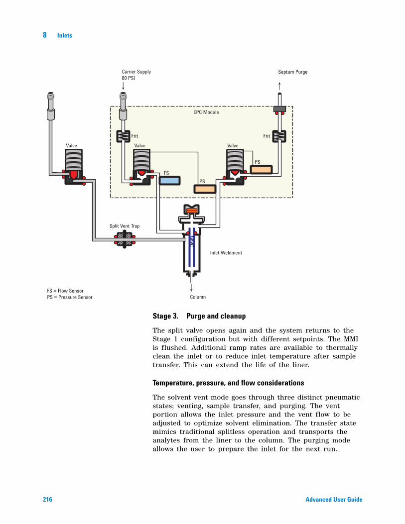
216 Advanced User Guide
8 Inlets
Stage 3. Purge and cleanup
The split valve opens again and the system returns to the Stage 1 configuration but with different setpoints. The MMI is flushed. Additional ramp rates are available to thermally clean the inlet or to reduce inlet temperature after sample transfer. This can extend the life of the liner.
Temperature, pressure, and flow considerations
The solvent vent mode goes through three distinct pneumatic states; venting, sample transfer, and purging. The vent portion allows the inlet pressure and the vent flow to be adjusted to optimize solvent elimination. The transfer state mimics traditional splitless operation and transports the analytes from the liner to the column. The purging mode allows the user to prepare the inlet for the next run.
Valve
Frit Frit
Valve
EPC Module
Valve
Split Vent Trap
Inlet Weldment
FS = Flow SensorPS = Pressure Sensor
FSPS
PS
Carrier Supply80 PSI
Septum Purge
Column
Inlets 8
Advanced User Guide 217
A fundamental difficulty with solvent vent mode is the potential loss of volatile analytes with the solvent. Several solutions are possible for this situation:
• The inlet liner can be packed with a more retentive material, such as Tenax. This greatly improves volatile analyte recovery but may impact recovery of higher boiling materials.
• Some of the solvent can be left in the liner when sample transfer begins. The residual solvent acts like a stationary phase and retains volatile material, but at the expense of a larger solvent peak.
• The inlet temperature can be reduced. This reduces the vapor pressure of the volatile analytes and permits higher recoveries.
Solvent removal can be speeded up by:
• Reducing pressure in the inlet during sample introduction—the Vent pressure parameter
• Increasing flow through the inlet—the Vent flow parameter
While all these possibilities do complicate use of the PTV, they provide increased flexibility and new potential to solve difficult problems.
Sequence of operations
These are the steps in a typical analysis using the solvent vent mode:
Table 32 The solvent vent process
Step Parameter Value
1 Before injection Flow at split vent Either Purge flow or Saver flow
Inlet pressure Derived from column setpoint
The system is resting, with Purge flow (or Saver flow, if on) through the inlet.
2 Prep Run begins Flow at split vent Vent flow setpoint
Inlet pressure Vent pressure setpoint
Setpoints change to prepare for injection. When GC is ready, the sample is injected. Inlet and oven temperature program Init times begin. Solvent venting and analyte trapping begin.
3 At Vent end time Flow at split vent None, split valve closed
Inlet pressure Column pressure setpoint
Solvent venting ends, analyte transfer begins as inlet heats up.
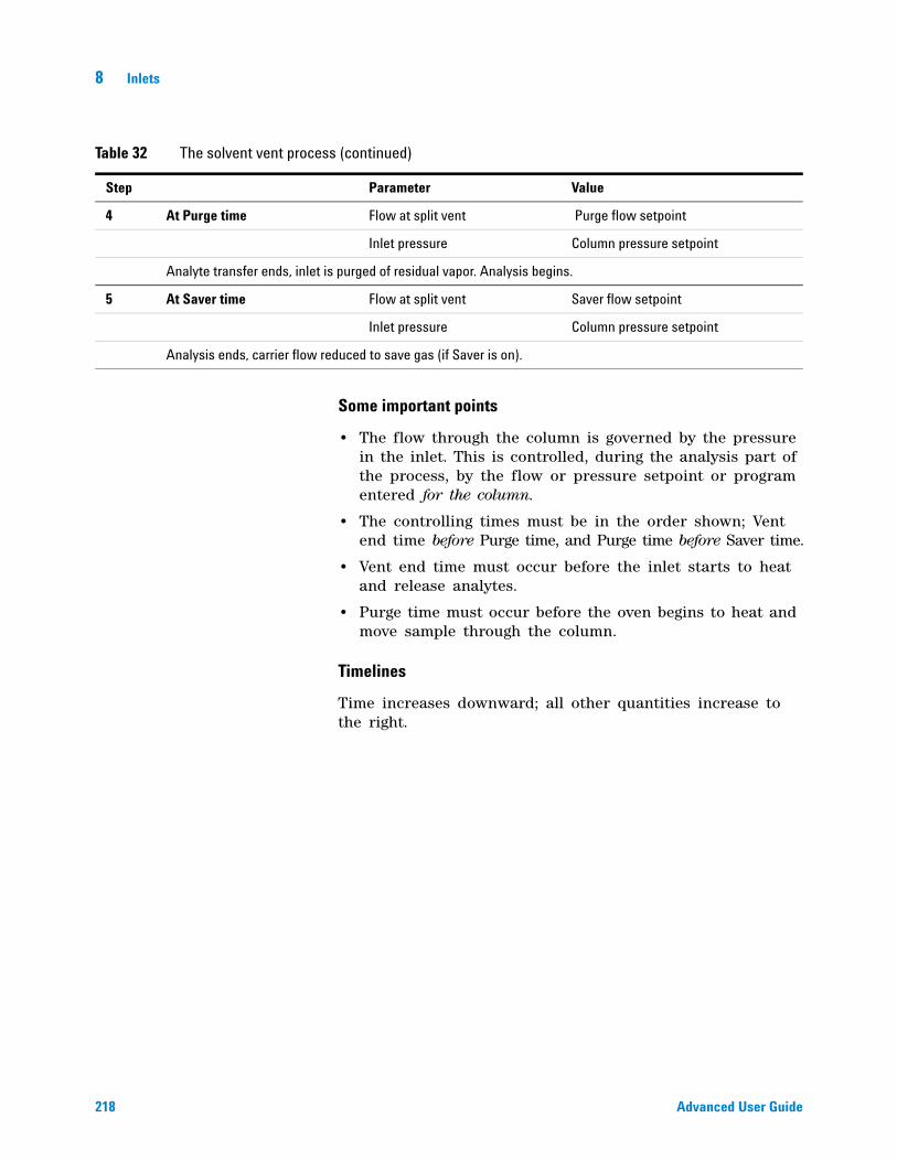
218 Advanced User Guide
8 Inlets
Some important points
• The flow through the column is governed by the pressure in the inlet. This is controlled, during the analysis part of the process, by the flow or pressure setpoint or program entered for the column.
• The controlling times must be in the order shown; Vent end time before Purge time, and Purge time before Saver time.
• Vent end time must occur before the inlet starts to heat and release analytes.
• Purge time must occur before the oven begins to heat and move sample through the column.
Timelines
Time increases downward; all other quantities increase to the right.
4 At Purge time Flow at split vent Purge flow setpoint
Inlet pressure Column pressure setpoint
Analyte transfer ends, inlet is purged of residual vapor. Analysis begins.
5 At Saver time Flow at split vent Saver flow setpoint
Inlet pressure Column pressure setpoint
Analysis ends, carrier flow reduced to save gas (if Saver is on).
Table 32 The solvent vent process (continued)
Step Parameter Value
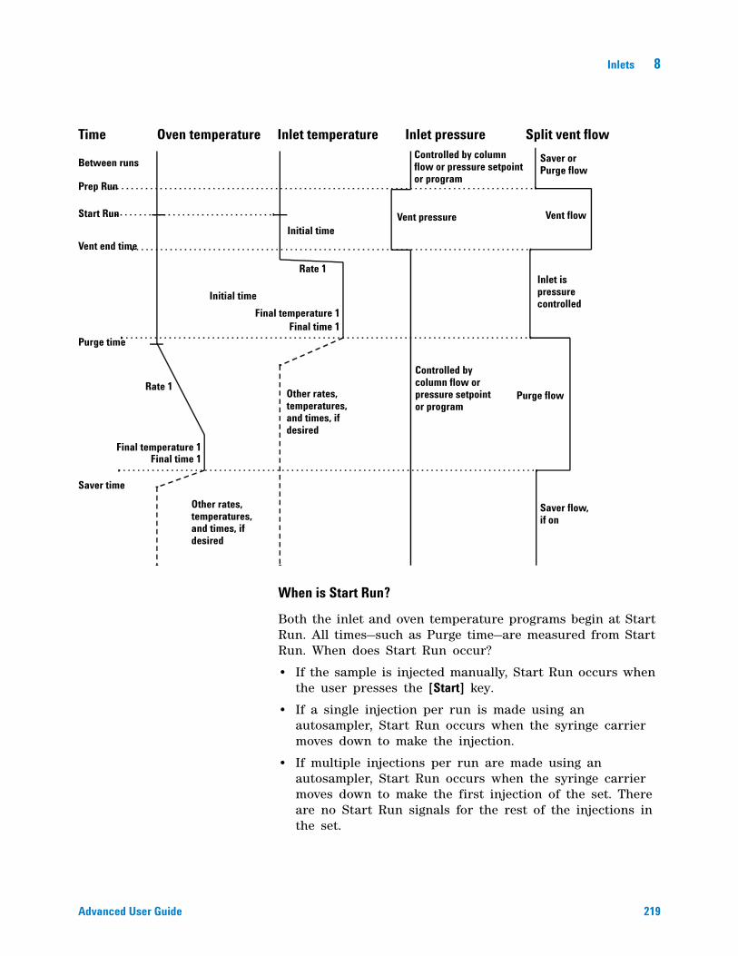
Inlets 8
Advanced User Guide 219
When is Start Run?
Both the inlet and oven temperature programs begin at Start Run. All times—such as Purge time—are measured from Start Run. When does Start Run occur?
• If the sample is injected manually, Start Run occurs when the user presses the [Start] key.
• If a single injection per run is made using an autosampler, Start Run occurs when the syringe carrier moves down to make the injection.
• If multiple injections per run are made using an autosampler, Start Run occurs when the syringe carrier moves down to make the first injection of the set. There are no Start Run signals for the rest of the injections in the set.
Time Oven temperature Inlet temperature Inlet pressure Split vent flow
Between runs
Prep Run
Start Run
Vent end time
Purge time
Saver time
Rate 1
Initial time
Final temperature 1Final time 1
Rate 1
Final temperature 1Final time 1
Other rates,temperatures,and times, ifdesired
Initial time
Other rates,temperatures,and times, ifdesired
Saver orPurge flow
Vent flow
Inlet ispressurecontrolled
Purge flow
Saver flow,if on
Controlled by columnflow or pressure setpointor program
Vent pressure
Controlled bycolumn flow orpressure setpointor program
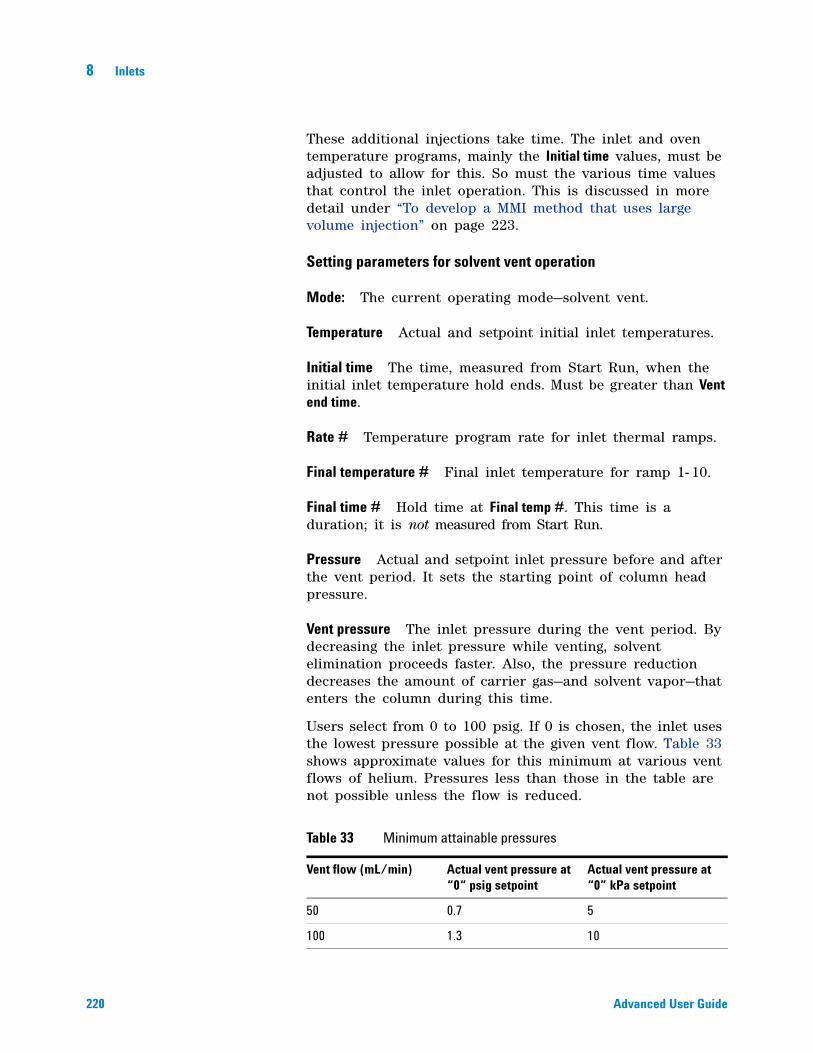
220 Advanced User Guide
8 Inlets
These additional injections take time. The inlet and oven temperature programs, mainly the Initial time values, must be adjusted to allow for this. So must the various time values that control the inlet operation. This is discussed in more detail under “To develop a MMI method that uses large volume injection” on page 223.
Setting parameters for solvent vent operation
Mode: The current operating mode—solvent vent.
Temperature Actual and setpoint initial inlet temperatures.
Initial time The time, measured from Start Run, when the initial inlet temperature hold ends. Must be greater than Vent end time.
Rate # Temperature program rate for inlet thermal ramps.
Final temperature # Final inlet temperature for ramp 1- 10.
Final time # Hold time at Final temp #. This time is a duration; it is not measured from Start Run.
Pressure Actual and setpoint inlet pressure before and after the vent period. It sets the starting point of column head pressure.
Vent pressure The inlet pressure during the vent period. By decreasing the inlet pressure while venting, solvent elimination proceeds faster. Also, the pressure reduction decreases the amount of carrier gas—and solvent vapor—that enters the column during this time.
Users select from 0 to 100 psig. If 0 is chosen, the inlet uses the lowest pressure possible at the given vent flow. Table 33 shows approximate values for this minimum at various vent flows of helium. Pressures less than those in the table are not possible unless the flow is reduced.
Table 33 Minimum attainable pressures
Vent flow (mL/min) Actual vent pressure at “0“ psig setpoint
Actual vent pressure at “0” kPa setpoint
50 0.7 5
100 1.3 10
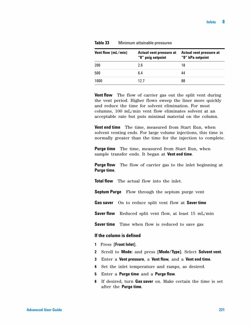
Inlets 8
Advanced User Guide 221
Vent flow The flow of carrier gas out the split vent during the vent period. Higher flows sweep the liner more quickly and reduce the time for solvent elimination. For most columns, 100 mL/min vent flow eliminates solvent at an acceptable rate but puts minimal material on the column.
Vent end time The time, measured from Start Run, when solvent venting ends. For large volume injections, this time is normally greater than the time for the injection to complete.
Purge time The time, measured from Start Run, when sample transfer ends. It began at Vent end time.
Purge flow The flow of carrier gas to the inlet beginning at Purge time.
Total flow The actual flow into the inlet.
Septum Purge Flow through the septum purge vent
Gas saver On to reduce split vent flow at Saver time
Saver flow Reduced split vent flow, at least 15 mL/min
Saver time Time when flow is reduced to save gas
If the column is defined
1 Press [Front Inlet].
2 Scroll to Mode: and press [Mode/Type]. Select Solvent vent.
3 Enter a Vent pressure, a Vent flow, and a Vent end time.
4 Set the inlet temperature and ramps, as desired.
5 Enter a Purge time and a Purge flow.
6 If desired, turn Gas saver on. Make certain the time is set after the Purge time.
200 2.6 18
500 6.4 44
1000 12.7 88
Table 33 Minimum attainable pressures
Vent flow (mL/min) Actual vent pressure at “0“ psig setpoint
Actual vent pressure at “0” kPa setpoint
222 Advanced User Guide
8 Inlets
7 Press [Prep Run] (see “Pre Run and Prep Run” on page 184) before manually injecting a sample.
If the column is not defined
1 Set up the parameters as described for the defined column case.
2 Set Total flow greater than the column flow plus the septum purge flow to guarantee adequate column flow.
MMI Direct Mode
MMI Direct Mode is a pneumatic configuration that allows on- column like behavior. In this mode, you still use a liner to trap involatile material but the sample can only enter the column.
Direct mode works best with direct connect liners. These liners form a seal with the column so that the sample cannot leak out of the liner. The inlet is held at a temperature below the solvent boiling point, just as in cool on- column (COC) during the injection. Pneumatically, the inlet is in forward pressure regulation, similar to the splitless portion of splitless mode. The inlet is then temperature programmed to transfer any remaining volatile material to the column.
The only control parameter for Direct Mode is inlet pressure. You can run the column in any of its normal control modes (constant pressure, constant flow, ramped pressure, ramped flow). Gas saver does not work in this mode as there is no purge state.
The next figure shows the flows with direct mode.
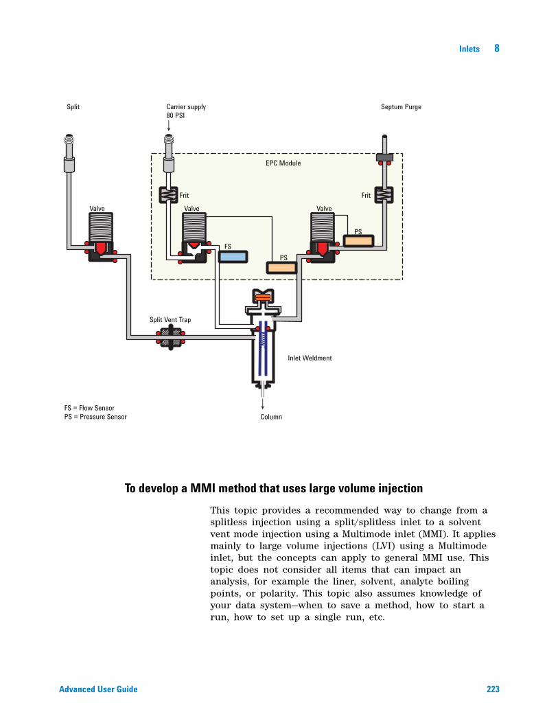
Inlets 8
Advanced User Guide 223
To develop a MMI method that uses large volume injection
This topic provides a recommended way to change from a splitless injection using a split/splitless inlet to a solvent vent mode injection using a Multimode inlet (MMI). It applies mainly to large volume injections (LVI) using a Multimode inlet, but the concepts can apply to general MMI use. This topic does not consider all items that can impact an analysis, for example the liner, solvent, analyte boiling points, or polarity. This topic also assumes knowledge of your data system—when to save a method, how to start a run, how to set up a single run, etc.
Split Carrier supply80 PSI
Septum Purge
Valve
Frit
EPC Module
PS
Inlet Weldment
Column
Split Vent Trap
FS = Flow SensorPS = Pressure Sensor
Valve Valve
Frit
PSFS

224 Advanced User Guide
8 Inlets
The main advantage of the MMI's solvent vent mode is that you can inject slowly into the inlet, allowing large amounts of solvent to evaporate in the liner (not in the split vent line), concentrating the analytes prior to injection. This requires an injector with variable speed injections, a "large" syringe, and knowledge of the sample and the solvent. When developing a solvent vent method, the goal for the injection is to determine the injection rates and temperatures needed to evaporate the solvent at the rate it enters the inlet. The development technique is to gradually scale up to an injection amount that produces a useful response. The most significant parameters are:
Inlet temperature. Hold the inlet temperature at or slightly below the solvent boiling point until after all the sample has been injected. This is important so that you do not boil away more volatile analytes, or boil away the solvent in the needle and trap your analytes there. An additional point to consider is that the boiling point of the earliest eluting analyte should be 100 °C > the boiling point of the solvent.
Injection speed. Estimate the evaporation rate of solvent exiting the needle based on solvent type, inlet temperature, vent flow, and pressure. Start with about half that number. Note that you have to make sure that you configure the syringe properly. If not, you will over- or under- load the inlet.
Vent time. Make sure the vent time setpoint is greater than the time the needle spends in the inlet. If the vent time is too short, you will overload and contaminate the column and inlet. Change the vent time as you upscale the method.
If using a MMI with an MSD, another tip for method development is to scan for solvent ions. Detecting the solvent ions can be useful in troubleshooting residual solvent bleed onto the column.
To develop a MMI method for large volume injection, try the following:
1 Determine a small injection volume that works on a split/splitless inlet in splitless mode. Choose a volume that does not currently overload the inlet.
2 Start with a 5–10 uL syringe and make sure the syringe is properly configured in the instrument and data system.
3 Make sure the column is configured.
Inlets 8
Advanced User Guide 225
4 Set up the inlet to perform a 1 uL injection. Use the split/splitless inlet method conditions, except:
• Start with the inlet temperature cold, near but slightly below the solvent boiling point. For example, if using methylene chloride (boiling point 39 °C), start with a temperature of 30–39 °C.
• Use Splitless mode.
• Ramp to the normal split/splitless inlet temperature
5 Note the response achieved.
6 Next, change the inlet mode to Solvent Vent.
7 Check the injector timings.
a Install an empty sample vial in the injector turret or tray.
b Input the injection rate (Draw, Dispense, and Inject rates) for the injector and increase the injection volume to 5 uL.
c Enter draft Solvent Vent parameters:
• Set a Vent Flow of 100 mL/min as a starting point.
• Keep the inlet isothermal for now
• Enter a Vent Pressure of 0 psi (0 kPa) until 0.1 min.
• Make an injection using the empty vial. Use a stopwatch or your GC's timer feature to time how long the needle is in the inlet.
8 Enter revised Solvent Vent mode parameters.
• Set the method's Vent Time to be about 0.05 min longer than the time the needle spends in the inlet.
• Set the inlet temperature initial Hold Time to be about 0.05 min longer than the vent pressure until time.
• Program the inlet to ramp quickly to the injection temperature. Make sure the ramp starts after the vent pressure until time.
• Set the Purge Flow to Split Vent to 30 mL/min. Set the purge time to be the vent pressure until time + 1 minute.
9 Make a 5 uL injection of your standard. You should see 5 times the response.
If the response of all analytes is too low:
• The dispense speed is too fast. Liquid was injected into the inlet and pushed out the vent.
226 Advanced User Guide
8 Inlets
• The vent time is too long. The inlet started to heat while the vent was open.
If the response of early eluters is too low:
• The inlet temperature is too high.
• The Vent Flow is too high.
If the response of late eluters is too low:
• The purge time is too short.
• The final inlet temperature is too low.
10 If you need more injection volume and the 5 uL worked to give 5X response, change the syringe to a larger one, for example 50 uL.
11 Set up the data system to perform a 25 uL injection.
12 Configure the syringe. Make sure the plunger speeds on the injector are still set properly.
13 Recheck the injector timings. See step 12.
14 Set a new vent time and initial inlet temperature time based on the new time the needle spends in the syringe.
15 Make a 25 uL injection of your standard. Again, you should see 5 times the response. If not, see step 13.
16 If you need more response, repeat steps 10 – 15 to increase to larger volume. Also try performing 5 x 5 uL injections, then 5 x 50 uL injections.
Multiple injections with the MMI
The preferred technique for concentrating analytes in the inlet liner is to use a single, large volume injection. Using a high capacity syringe and one septum puncture reduces the possibility of contamination and generally improves results when compared against a multiple septum puncture technique. However, if needed, you can perform multiple septum punctures during the vent time. This technique requires an Agilent data system and automatic liquid sampler.
Data system requirements
An Agilent data system is necessary for multiple injection because the needed parameters are not available through the GC keyboard.
GC ChemStation Software revision B.04.01 SP1 or later.

Inlets 8
Advanced User Guide 227
MSD ChemStation Software revision E.02.00 SP2 or later
EZChrom Software revision 3.3.2 or later
Setting parameters for the inlet in solvent vent mode
Set or configure the following parameters in the data system's 7890A GC method editor.
Syringe size — Verify the syringe size is configured correctly. The configured syringe size changes the available choices for injection volume.
Injection volume — Select the injection volume, then enter a number of injections. The total injection volume will be displayed.
Multiple Injection Delay — A pause time, in seconds, between injections. This is added to the minimum hardware cycle time.
Preinjection washes and pumps are performed only before the first injection of a multiple injection set.
Postinjection washes are performed only after the last injection in a multiple injection set.
An example
These values were used for a sample with a broad range of boiling points.
Table 34 General parameters
Name Value
Sample C10 to C44 hydrocarbons in hexane
Mode Solvent vent
MMI liner Glass wool packed
Injection volume One 10.0 μL injection (25 μL syringe)
Injection speed Fast
Column 30 m x 320 μm x 0.25 μm -5, part number 19091J-413
Column flow 4 mL/min constant flow
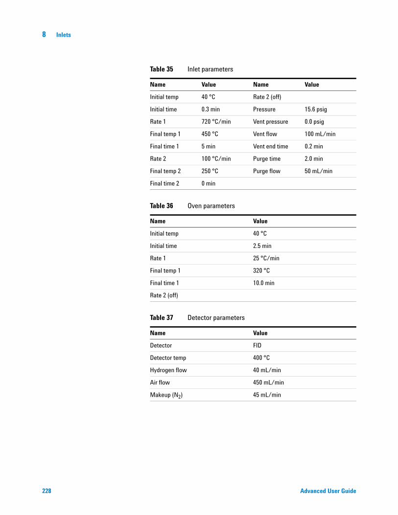
228 Advanced User Guide
8 Inlets
Table 35 Inlet parameters
Name Value Name Value
Initial temp 40 °C Rate 2 (off)
Initial time 0.3 min Pressure 15.6 psig
Rate 1 720 °C/min Vent pressure 0.0 psig
Final temp 1 450 °C Vent flow 100 mL/min
Final time 1 5 min Vent end time 0.2 min
Rate 2 100 °C/min Purge time 2.0 min
Final temp 2 250 °C Purge flow 50 mL/min
Final time 2 0 min
Table 36 Oven parameters
Name Value
Initial temp 40 °C
Initial time 2.5 min
Rate 1 25 °C/min
Final temp 1 320 °C
Final time 1 10.0 min
Rate 2 (off)
Table 37 Detector parameters
Name Value
Detector FID
Detector temp 400 °C
Hydrogen flow 40 mL/min
Air flow 450 mL/min
Makeup (N2) 45 mL/min
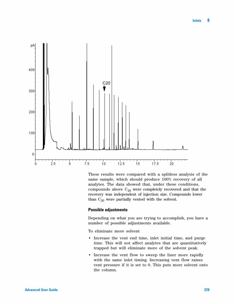
Inlets 8
Advanced User Guide 229
These results were compared with a splitless analysis of the same sample, which should produce 100% recovery of all analytes. The data showed that, under these conditions, compounds above C20 were completely recovered and that the recovery was independent of injection size. Compounds lower than C20 were partially vented with the solvent.
Possible adjustments
Depending on what you are trying to accomplish, you have a number of possible adjustments available.
To eliminate more solvent
• Increase the vent end time, inlet initial time, and purge time. This will not affect analytes that are quantitatively trapped but will eliminate more of the solvent peak.
• Increase the vent flow to sweep the liner more rapidly with the same inlet timing. Increasing vent flow raises vent pressure if it is set to 0. This puts more solvent onto the column.
C20
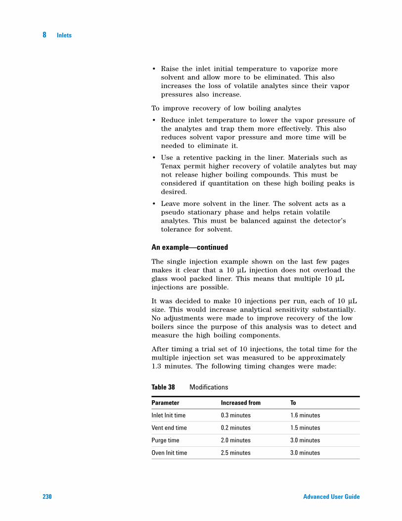
230 Advanced User Guide
8 Inlets
• Raise the inlet initial temperature to vaporize more solvent and allow more to be eliminated. This also increases the loss of volatile analytes since their vapor pressures also increase.
To improve recovery of low boiling analytes
• Reduce inlet temperature to lower the vapor pressure of the analytes and trap them more effectively. This also reduces solvent vapor pressure and more time will be needed to eliminate it.
• Use a retentive packing in the liner. Materials such as Tenax permit higher recovery of volatile analytes but may not release higher boiling compounds. This must be considered if quantitation on these high boiling peaks is desired.
• Leave more solvent in the liner. The solvent acts as a pseudo stationary phase and helps retain volatile analytes. This must be balanced against the detector’s tolerance for solvent.
An example—continued
The single injection example shown on the last few pages makes it clear that a 10 μL injection does not overload the glass wool packed liner. This means that multiple 10 μL injections are possible.
It was decided to make 10 injections per run, each of 10 μL size. This would increase analytical sensitivity substantially. No adjustments were made to improve recovery of the low boilers since the purpose of this analysis was to detect and measure the high boiling components.
After timing a trial set of 10 injections, the total time for the multiple injection set was measured to be approximately 1.3 minutes. The following timing changes were made:
Table 38 Modifications
Parameter Increased from To
Inlet Init time 0.3 minutes 1.6 minutes
Vent end time 0.2 minutes 1.5 minutes
Purge time 2.0 minutes 3.0 minutes
Oven Init time 2.5 minutes 3.0 minutes
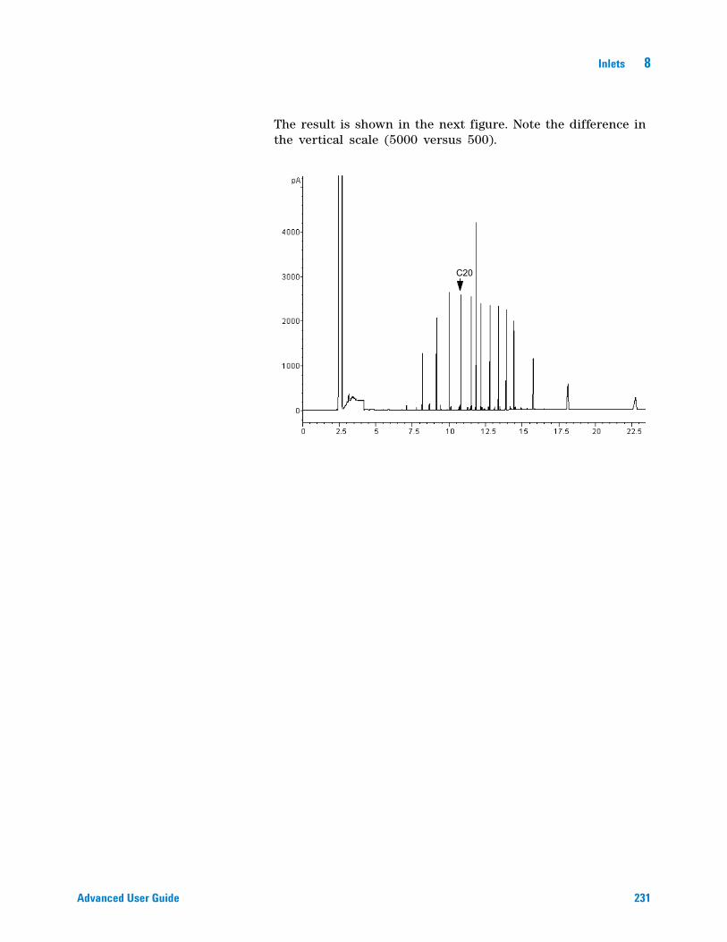
Inlets 8
Advanced User Guide 231
The result is shown in the next figure. Note the difference in the vertical scale (5000 versus 500).
C20
232 Advanced User Guide
8 Inlets
About the Packed Column Inlet
This inlet is also known as the purged packed inlet (PP). It is used with packed columns when high- efficiency separations are not required. It can also be used with wide- bore capillary columns, if flows greater than 10 mL/min are acceptable.
If the columns are not defined (packed columns and undefined capillary columns), the inlet is usually flow- controlled. If capillary columns are used and the columns in the flow path are defined, the inlet is normally pressure- controlled but can be put into the flow control mode.
The figure shows the inlet in the capillary column mode, with the column defined and the flow controlled by pressure.
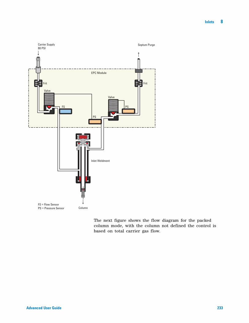
Inlets 8
Advanced User Guide 233
The next figure shows the flow diagram for the packed column mode, with the column not defined the control is based on total carrier gas flow.
Valve
Frit Frit
Valve
EPC Module
Inlet Weldment
FS = Flow Sensor
PS = Pressure Sensor
FS PS
Carrier Supply
80 PSI
Septum Purge
Column
PS
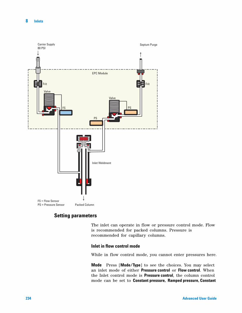
234 Advanced User Guide
8 Inlets
Setting parameters
The inlet can operate in flow or pressure control mode. Flow is recommended for packed columns. Pressure is recommended for capillary columns.
Inlet in flow control mode
While in flow control mode, you cannot enter pressures here.
Mode Press [Mode/Type] to see the choices. You may select an inlet mode of either Pressure control or Flow control. When the Inlet control mode is Pressure control, the column control mode can be set to Constant pressure, Ramped pressure, Constant
Valve
Frit Frit
Valve
EPC Module
Inlet Weldment
FS = Flow Sensor
PS = Pressure Sensor
FS PS
Carrier Supply
80 PSI
Septum Purge
Packed Column
PS
Inlets 8
Advanced User Guide 235
flow, or Ramped flow. The column control mode is set from the Column parameters display. When the Inlet control mode is Flow control, only column flow can be set on the Column parameters display.
Temperature The setpoint and actual temperature values.
Pressure The actual pressure (in psi, bar, or kPa) supplied to the inlet. You cannot enter a setpoint here.
Total flow Enter your setpoint here, actual value is displayed. Inlet is mass flow controlled.
Septum purge The setpoint and actual flow, in mL/min, through the septum purge line, typically 1 to 5 mL/min
Inlet in pressure control mode
While in pressure control mode, you cannot enter flows here.
Mode Press [Mode/Type] to see the choices. You may select an inlet mode of either Pressure control or Flow control. When the Inlet control mode is Pressure control, the column control mode can be set to Constant pressure, Ramped pressure, Constant flow, or Ramped flow. The column control mode is set from the Column parameters display. When the Inlet control mode is Flow control, only column flow can be set on the Column parameters display.
Temperature The setpoint and actual temperature values of the inlet.
Pressure Enter your setpoint here (in psi, bar, or kPa). The actual value is displayed.
Total flow The actual total flow to the inlet. This is a reported value, not a setpoint.
Septum purge The setpoint and actual flow, in mL/min, through the septum purge line, typically 1 to 5 mL/min
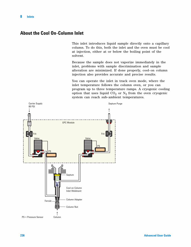
236 Advanced User Guide
8 Inlets
About the Cool On-Column Inlet
This inlet introduces liquid sample directly onto a capillary column. To do this, both the inlet and the oven must be cool at injection, either at or below the boiling point of the solvent.
Because the sample does not vaporize immediately in the inlet, problems with sample discrimination and sample alteration are minimized. If done properly, cool- on column injection also provides accurate and precise results.
You can operate the inlet in track oven mode, where the inlet temperature follows the column oven, or you can program up to three temperature ramps. A cryogenic cooling option that uses liquid CO2 or N2 from the oven cryogenic system can reach sub- ambient temperatures.
Valve
Frit Frit
Valve
EPC Module
Cool on ColumnInlet Weldment
PS = Pressure Sensor
PS
PS
Carrier Supply80 PSI
Septum Purge
Column
Septum
Column AdapterFerrule
Column Nut
Column
Inlets 8
Advanced User Guide 237
Setup modes of the COC inlet
The COC inlet hardware must be set up for one of three usages, depending on the type of injection and column size.
• 0.25 mm or 0.32 mm automated on- column. Use predrilled septa.
• 0.53 mm automatic on- column or retention gap
• 0.2 mm manual
To select the correct hardware for a column and injection type, refer to Maintaining Your GC.
Retention gaps
Because the sample is injected directly onto the column, it is strongly suggested that a retention gap—or guard column—be used to protect your column. A retention gap is a deactivated column that is connected between the inlet and the analytical column. If you choose to use one, it is suggested that at least 1 m of retention gap be installed per 1 μL of sample injected. Information on ordering retention gaps can be found in the Agilent catalog for consumables and supplies.
If you are using a retention gap and are operating with the column defined, the length of the retention gap could affect the calculations for flow and velocity through your column. If your retention gap is the same inside diameter as your column, it is a good idea to add the retention gap and column length before entering the number on the Configure Column parameter list. If the retention gap inside diameter is larger than your column, this step may not be necessary.
COC inlet temperature control
CryoBlast (optional)
CryoBlast shortens the cycle time between runs. If you have a CO2 or N2 cryogenic valve and the CryoBlast feature, you can cool the inlet to –37 °C in either the track oven or temperature program modes.
The CryoBlast accessory uses coolant from the oven cryogenic system.
238 Advanced User Guide
8 Inlets
Track oven mode
In the Track oven mode, the inlet temperature stays 3 °C higher than the oven temperature throughout the oven program. You cannot enter a temperature setpoint—it is set automatically. If you have CryoBlast, the inlet will track oven temperatures to –40°C; without CryoBlast, the lower limit is set by room temperature.
Temperature programming mode
In this mode, you can enter up to three temperature ramps in the inlet parameter list so that the inlet and the oven operate independently. This is the recommended mode if operating below –20 °C.
At these very low oven temperatures, the inlet temperature should be at least 20 °C higher than the oven temperature. This will be more than adequate for solvent focusing.
At temperatures greater than ambient, the inlet should always be at least 3 °C warmer than the oven for proper control of the inlet temperature.
The oven temperature program controls the run. If it is longer than the inlet temperature program, the inlet will remain at its final temperature until the oven program (and the run) ends.
Cryogenic considerations
When using track oven mode with a cryogenic oven, all other inlets must be off or in track oven mode.
If cryo is turned on, and if the inlet is cooled during a run, cryogen is used to achieve the setpoint. This may have a negative impact on the chromatographic performance of the oven and cause distorted peaks.
The inlet uses the same cryo coolant as configured for the oven.
Setting COC inlet flows/pressures
1 Configure capillary column to inlet—select constant flow or pressure.
2 Set column flow, linear velocity, or inlet pressure.
3 Set Septum Purge, typically 3 to 10 mL/min.
Inlets 8
Advanced User Guide 239
Setting COC inlet parameters
Track oven mode
1 Press [Front Inlet] or [Back Inlet].
2 Press [Mode/Type] and select Track oven.
There is no setpoint for Track oven mode.
Ramped temperature mode
1 Press [Front Inlet] or [Back Inlet].
2 Press [Mode/Type] and select Ramped temp.
3 Enter a value for Temp. This is the starting temperature.
4 Enter an Init time. This is the length of time the inlet will stay at the starting temperature after a run has begun.
5 Enter Rate 1. This is the rate at which the inlet will be heated or cooled. A Rate of 0 halts further programming.
6 Enter Final temp 1. This is the inlet temperature at the end of the first ramp.
7 Enter Final time 1. This is the number of minutes the inlet holds Final temp 1.
8 To enter a second (or third) ramp, scroll to the appropriate Rate line and repeat steps 5 through 7.
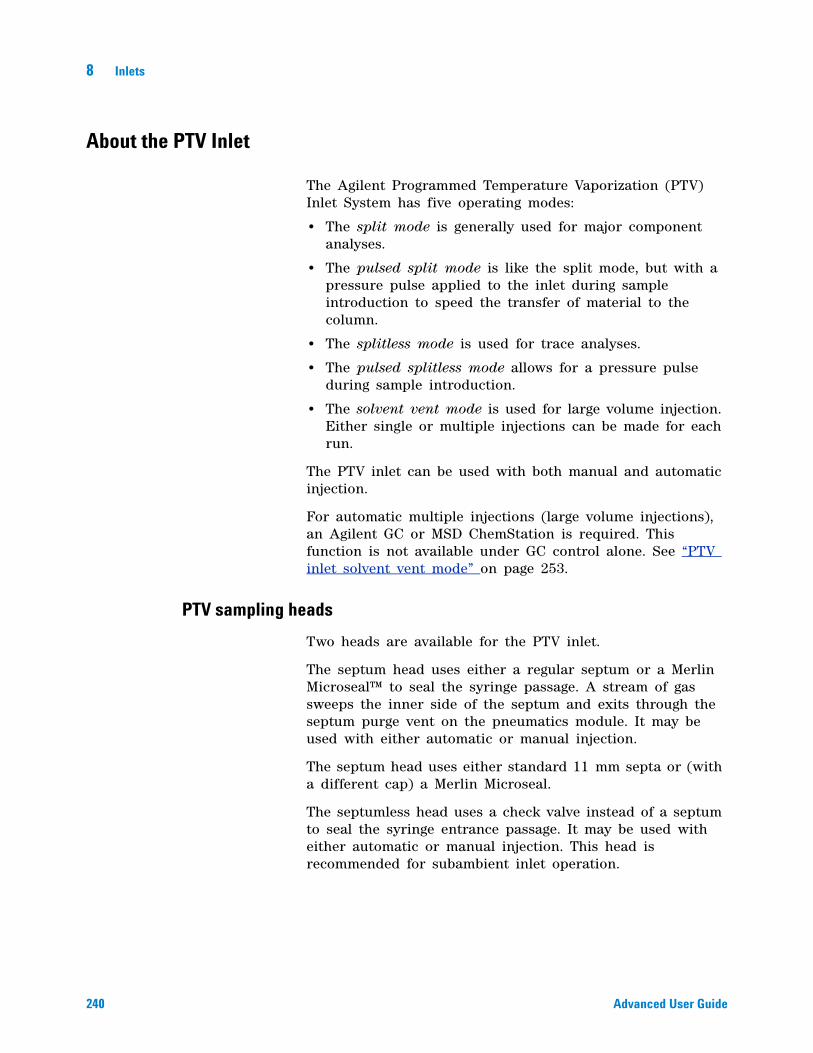
240 Advanced User Guide
8 Inlets
About the PTV Inlet
The Agilent Programmed Temperature Vaporization (PTV) Inlet System has five operating modes:
• The split mode is generally used for major component analyses.
• The pulsed split mode is like the split mode, but with a pressure pulse applied to the inlet during sample introduction to speed the transfer of material to the column.
• The splitless mode is used for trace analyses.
• The pulsed splitless mode allows for a pressure pulse during sample introduction.
• The solvent vent mode is used for large volume injection. Either single or multiple injections can be made for each run.
The PTV inlet can be used with both manual and automatic injection.
For automatic multiple injections (large volume injections), an Agilent GC or MSD ChemStation is required. This function is not available under GC control alone. See “PTV inlet solvent vent mode” on page 253.
PTV sampling heads
Two heads are available for the PTV inlet.
The septum head uses either a regular septum or a Merlin Microseal™ to seal the syringe passage. A stream of gas sweeps the inner side of the septum and exits through the septum purge vent on the pneumatics module. It may be used with either automatic or manual injection.
The septum head uses either standard 11 mm septa or (with a different cap) a Merlin Microseal.
The septumless head uses a check valve instead of a septum to seal the syringe entrance passage. It may be used with either automatic or manual injection. This head is recommended for subambient inlet operation.
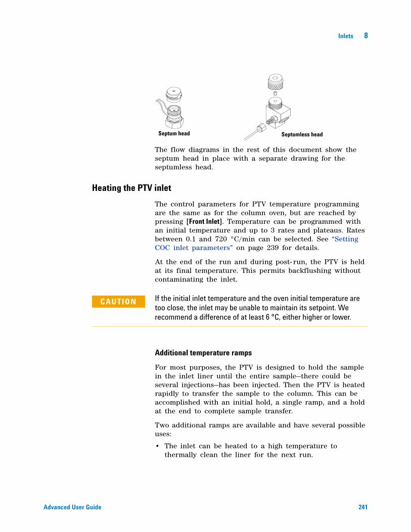
Inlets 8
Advanced User Guide 241
The flow diagrams in the rest of this document show the septum head in place with a separate drawing for the septumless head.
Heating the PTV inlet
The control parameters for PTV temperature programming are the same as for the column oven, but are reached by pressing [Front Inlet]. Temperature can be programmed with an initial temperature and up to 3 rates and plateaus. Rates between 0.1 and 720 °C/min can be selected. See “Setting COC inlet parameters” on page 239 for details.
At the end of the run and during post- run, the PTV is held at its final temperature. This permits backflushing without contaminating the inlet.
Additional temperature ramps
For most purposes, the PTV is designed to hold the sample in the inlet liner until the entire sample—there could be several injections—has been injected. Then the PTV is heated rapidly to transfer the sample to the column. This can be accomplished with an initial hold, a single ramp, and a hold at the end to complete sample transfer.
Two additional ramps are available and have several possible uses:
• The inlet can be heated to a high temperature to thermally clean the liner for the next run.
Septum head Septumless head
CAUTION If the initial inlet temperature and the oven initial temperature are too close, the inlet may be unable to maintain its setpoint. We recommend a difference of at least 6 °C, either higher or lower.
242 Advanced User Guide
8 Inlets
• The inlet can be programmed downward—just set the Final temp below the previous temperature—to reduce thermal stress on the inlet.
• Downward programming can be used to prepare the inlet for the next run. This can reduce cycle time for greater sample throughput.
Cooling the PTV inlet
If cryo is turned on, and if the inlet is cooled during a run, cryogen is used to achieve the setpoint. This may have a negative impact on the chromatographic performance of the oven and cause distorted peaks.
The sample may be injected into either a cooled or heated inlet. The initial inlet temperature can be reduced to –60 °C (with CO2 cooling) or to –160 °C (with liquid N2 cooling).
The inlet uses the same coolant as configured for the oven.
PTV inlet split and pulsed split modes
The two split modes—with or without a pressure pulse—divide the gas stream entering the inlet between the column flow, the split vent flow through the solenoid valve, and the septum purge flow. The ratio of the split vent flow to the column flow is called the split ratio.
The next figure shows the flows with the septum head. Flows with the septumless head are the same except that the septum purge flow bypasses the head.

Inlets 8
Advanced User Guide 243
Cold split introduction
For cold split sample introduction, use an initial inlet temperature below the normal boiling point of the solvent. If the liner volume is enough to hold all the vaporized solvent, start the first inlet temperature ramp at 0.1 minutes with a high heating rate (500 °C/min or higher). The final temperature should be high enough to volatilize the heaviest analytes from the liner and should be held for at least 5 minutes. A final temperature of 350 °C for 5 minutes has proven sufficient to quantitatively transfer C44.
For larger injection volumes or to eliminate the solvent, hold the initial temperature long enough to vent the solvent through the split vent and then begin the first ramp. Use a fast rate for thermally stable analytes. Slower rates may help minimize thermal degradation in the inlet.
Valve
Frit Frit
Valve
EPC Module
Valve
Split Vent Trap
PTV Inlet Weldment
FS = Flow SensorPS = Pressure Sensor
FSPS
PS
Split Carrier Supply80 PSI
Septum Purge
Column
244 Advanced User Guide
8 Inlets
A single temperature ramp is enough for the injection process. The remaining ramps may be used to clean the liner or to reduce the inlet temperature in preparation for the next injection.
Hot split introduction
For hot split introduction, set an initial temperature high enough to volatilize the analytes. No additional thermal parameters are required as the inlet will maintain the setpoint throughout the run.
Because of the small liner volume (about 120 microliters), the PTV has a limited injection capacity with hot split introduction. Injection volumes exceeding 1 μL in the hot split mode may overflow the inlet causing analytical problems. Cold split introduction avoids this potential problem.
Setting parameters for split mode operation
Mode: The current operating mode—split or pulsed split
Temperature Actual and setpoint inlet temperatures.
Initial temperature Starting temperature for the inlet.
Initial time Hold time at the inlet initial temperature.
Rate # Temperature program rates for inlet thermal ramps.
Final temp # Final inlet temperature for ramps 1, 2, and 3.
Final time # Hold time at Final temp 1, 2, and 3.
Pressure Actual and setpoint inlet pressure. Controls capillary column flow and linear velocity.
Split ratio The ratio of split flow to column flow. Column flow is set in the column parameter list. This line does not appear if a column in the flow path is not defined.
Split flow Flow, in mL/min, from the split/purge vent. This line does not appear if a column in the flow path is not defined.
Inlets 8
Advanced User Guide 245
Total flow These are the actual and setpoint values of the total flow into the inlet, which is the sum of the split flow, column flow, and septum purge flow. When you change the total flow, the split ratio and split flow change while the column flow and pressure remain the same.
Septum Purge Flow through the septum purge vent.
Gas saver On to reduce split vent flow at Saver time.
Saver flow Reduced split vent flow, at least 15 mL/min.
Saver time Time when flow is reduced to save gas.
If all columns in the flow path are defined
1 Press [Front Inlet].
2 Scroll to Mode: and press [Mode/Type]. Select Split or Pulsed split.
3 Set the inlet temperature (Initial temperature) and any desired ramps.
4 If you want a specific split ratio, scroll to Split ratio and enter that number. The split flow will be calculated and set for you.
5 If you want a specific split flow, scroll to Split flow and enter that number. The split ratio will be calculated and displayed for you.
6 If you selected Pulsed split, enter values for Pulsed pressure (pressure at injection) and Pulse time (minutes after injection to return to normal pressure).
7 If desired, turn on Gas saver. Set the Saver time after the injection time.
8 Press [Prep Run] before manually injecting the sample if the Gas Saver is on (see “Pre Run and Prep Run” on page 184).
If a column in the flow path is not defined
1 Press [Front Inlet].
2 Set the inlet temperature (Initial temperature) and any desired ramps.
3 Set other parameters as described for a defined column.
4 Set Total flow into the inlet. Measure flows out of the split vent and septum purge vent using a flow meter.
246 Advanced User Guide
8 Inlets
5 Subtract the septum purge flow and split vent flow from Total flow to get column flow.
6 Calculate the split ratio (split vent flow/column flow). Adjust as needed
PTV inlet splitless and pulsed splitless modes
In these modes—with or without a pressure pulse—the split vent valve is closed during injection and vaporization of the sample and stays so while the sample transfers to the column.
At a specified time after injection, the valve opens to sweep vapors left in the liner out the split vent. This avoids solvent tailing due to the large inlet volume and small column flow rate.
The figures show the flows with the septum head. Flows with the septumless head are the same except that the septum purge flow bypasses the head.
Stage 1. Sample injection
With the split vent valve closed, the sample and solvent transfer to the column.
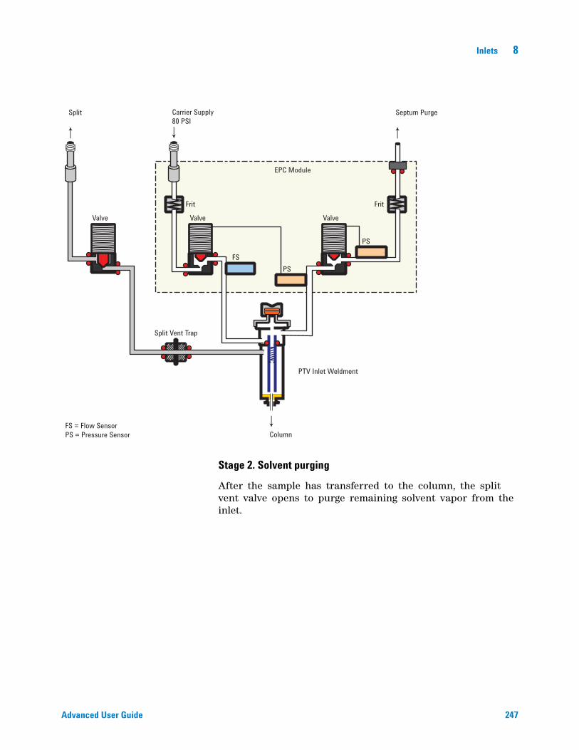
Inlets 8
Advanced User Guide 247
Stage 2. Solvent purging
After the sample has transferred to the column, the split vent valve opens to purge remaining solvent vapor from the inlet.
Valve
Frit Frit
Valve
EPC Module
Valve
Split Vent Trap
PTV Inlet Weldment
FS = Flow SensorPS = Pressure Sensor
FSPS
PS
Split Carrier Supply80 PSI
Septum Purge
Column
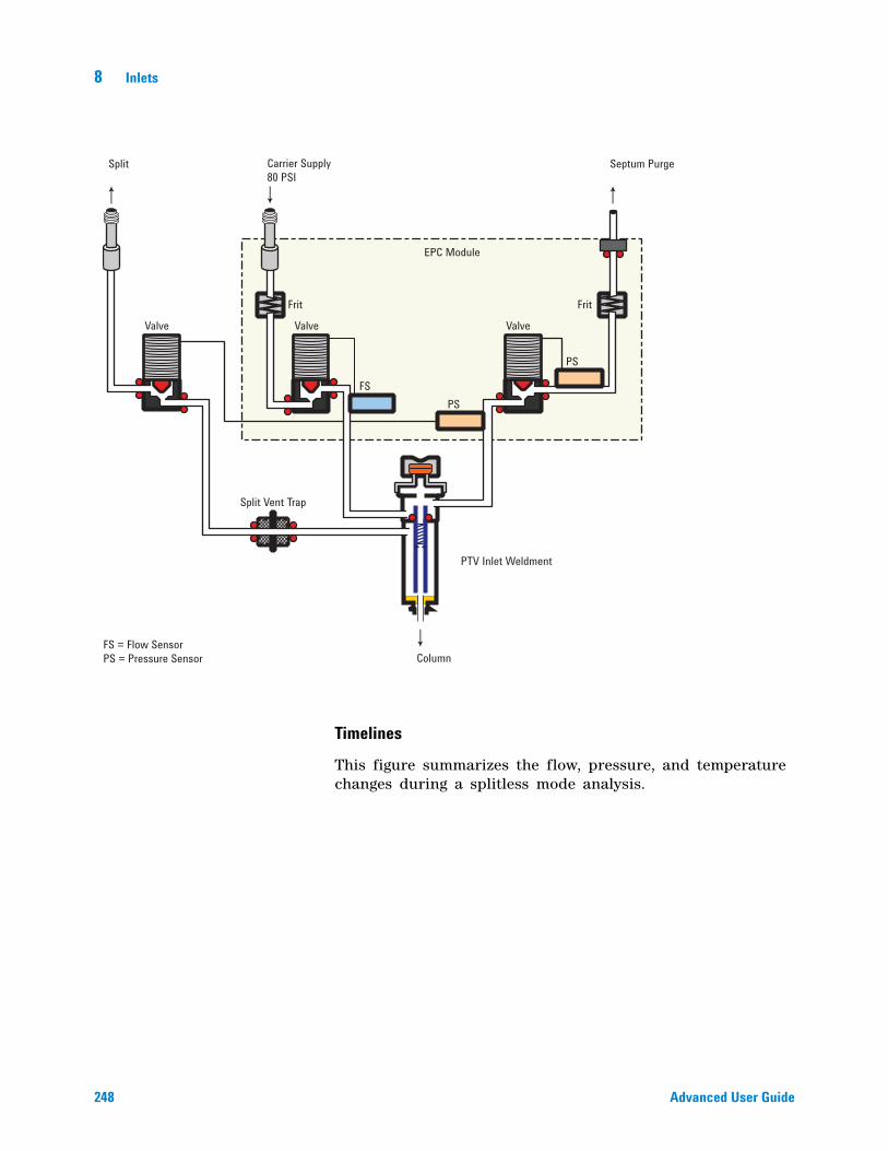
248 Advanced User Guide
8 Inlets
Timelines
This figure summarizes the flow, pressure, and temperature changes during a splitless mode analysis.
Valve
Frit Frit
Valve
EPC Module
Valve
Split Vent Trap
PTV Inlet Weldment
FS = Flow SensorPS = Pressure Sensor
FSPS
PS
Split Carrier Supply80 PSI
Septum Purge
Column
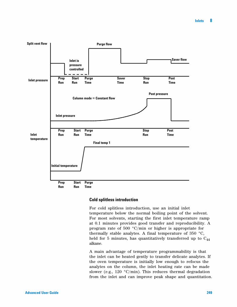
Inlets 8
Advanced User Guide 249
Cold splitless introduction
For cold splitless introduction, use an initial inlet temperature below the normal boiling point of the solvent. For most solvents, starting the first inlet temperature ramp at 0.1 minutes provides good transfer and reproducibility. A program rate of 500 °C/min or higher is appropriate for thermally stable analytes. A final temperature of 350 °C, held for 5 minutes, has quantitatively transferred up to C44 alkane.
A main advantage of temperature programmability is that the inlet can be heated gently to transfer delicate analytes. If the oven temperature is initially low enough to refocus the analytes on the column, the inlet heating rate can be made slower (e.g., 120 °C/min). This reduces thermal degradation from the inlet and can improve peak shape and quantitation.
Split vent flow Purge flow
Saver flow
Inlet pressure
Inlet is pressure controlled
Post pressure
Inlet pressure
Inlet temperature
Final temp 1
Initial temperature
Prep Run
Start Run
Purge Time
Saver Time
Stop Run
Post Time
Post Time
Stop Run
Purge Time
Purge Time
Prep Run
Prep Run
Start Run
Start Run
Column mode = Constant flow
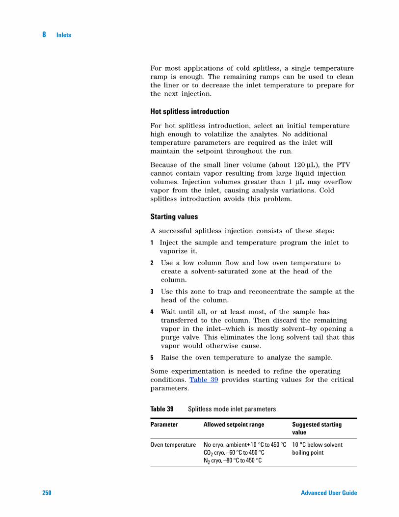
250 Advanced User Guide
8 Inlets
For most applications of cold splitless, a single temperature ramp is enough. The remaining ramps can be used to clean the liner or to decrease the inlet temperature to prepare for the next injection.
Hot splitless introduction
For hot splitless introduction, select an initial temperature high enough to volatilize the analytes. No additional temperature parameters are required as the inlet will maintain the setpoint throughout the run.
Because of the small liner volume (about 120 μL), the PTV cannot contain vapor resulting from large liquid injection volumes. Injection volumes greater than 1 μL may overflow vapor from the inlet, causing analysis variations. Cold splitless introduction avoids this problem.
Starting values
A successful splitless injection consists of these steps:
1 Inject the sample and temperature program the inlet to vaporize it.
2 Use a low column flow and low oven temperature to create a solvent- saturated zone at the head of the column.
3 Use this zone to trap and reconcentrate the sample at the head of the column.
4 Wait until all, or at least most, of the sample has transferred to the column. Then discard the remaining vapor in the inlet—which is mostly solvent—by opening a purge valve. This eliminates the long solvent tail that this vapor would otherwise cause.
5 Raise the oven temperature to analyze the sample.
Some experimentation is needed to refine the operating conditions. Table 39 provides starting values for the critical parameters.
Table 39 Splitless mode inlet parameters
Parameter Allowed setpoint range Suggested starting value
Oven temperature No cryo, ambient+10 °C to 450 °C CO2 cryo, –60 °C to 450 °C N2 cryo, –80 °C to 450 °C
10 °C below solvent boiling point
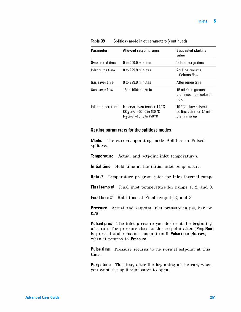
Inlets 8
Advanced User Guide 251
Setting parameters for the splitless modes
Mode: The current operating mode—Splitless or Pulsed splitless.
Temperature Actual and setpoint inlet temperatures.
Initial time Hold time at the initial inlet temperature.
Rate # Temperature program rates for inlet thermal ramps.
Final temp # Final inlet temperature for ramps 1, 2, and 3.
Final time # Hold time at Final temp 1, 2, and 3.
Pressure Actual and setpoint inlet pressure in psi, bar, or kPa
Pulsed pres The inlet pressure you desire at the beginning of a run. The pressure rises to this setpoint after [Prep Run] is pressed and remains constant until Pulse time elapses, when it returns to Pressure.
Pulse time Pressure returns to its normal setpoint at this time.
Purge time The time, after the beginning of the run, when you want the split vent valve to open.
Oven initial time 0 to 999.9 minutes ≥ Inlet purge time
Inlet purge time 0 to 999.9 minutes 2 x Liner volume Column flow
Gas saver time 0 to 999.9 minutes After purge time
Gas saver flow 15 to 1000 mL/min 15 mL/min greater than maximum column flow
Inlet temperature No cryo, oven temp + 10 °C CO2 cryo, –50 °C to 450 °C N2 cryo, –60 °C to 450 °C
10 °C below solvent boiling point for 0.1min, then ramp up
Table 39 Splitless mode inlet parameters (continued)
Parameter Allowed setpoint range Suggested starting value
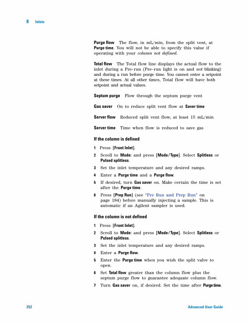
252 Advanced User Guide
8 Inlets
Purge flow The flow, in mL/min, from the split vent, at Purge time. You will not be able to specify this value if operating with your column not defined.
Total flow The Total flow line displays the actual flow to the inlet during a Pre- run (Pre- run light is on and not blinking) and during a run before purge time. You cannot enter a setpoint at these times. At all other times, Total flow will have both setpoint and actual values.
Septum purge Flow through the septum purge vent
Gas saver On to reduce split vent flow at Saver time
Server flow Reduced split vent flow, at least 15 mL/min
Server time Time when flow is reduced to save gas
If the column is defined
1 Press [Front Inlet].
2 Scroll to Mode: and press [Mode/Type]. Select Splitless or Pulsed splitless.
3 Set the inlet temperature and any desired ramps.
4 Enter a Purge time and a Purge flow.
5 If desired, turn Gas saver on. Make certain the time is set after the Purge time.
6 Press [Prep Run] (see “Pre Run and Prep Run” on page 184) before manually injecting a sample. This is automatic if an Agilent sampler is used.
If the column is not defined
1 Press [Front Inlet].
2 Scroll to Mode: and press [Mode/Type]. Select Splitless or Pulsed splitless.
3 Set the inlet temperature and any desired ramps.
4 Enter a Purge flow.
5 Enter the Purge time when you wish the split valve to open.
6 Set Total flow greater than the column flow plus the septum purge flow to guarantee adequate column flow.
7 Turn Gas saver on, if desired. Set the time after Purge time.
Inlets 8
Advanced User Guide 253
8 Press [Prep Run] (see “Pre Run and Prep Run” on page 184) before manually injecting a sample. This is automatic if an Agilent sampler is used.
PTV inlet solvent vent mode
This mode is typically used for large volume injections. For single injection use a 50 or 100 µL syringe with variable plunger speed—slowly, 5 to 30 seconds.
The sample is injected into a cold inlet. If conditions are properly chosen and the sample is suitable, analytes deposit in the inlet liner while the solvent evaporates and is swept out. Large or multiple injections can be used to concentrate sample in the inlet before transferring to the column for analysis.
The figure shows the flows with the septum head. Flows with the septumless head are the same except that the septum purge flow bypasses the head.
Stage 1. Sample and vent
During sampling and venting, the split valve is open. The inlet is at Initial temperature, which is at or below the solvent boiling point.
Solvent vapors are swept out the vent, while sample deposits on the liner walls or packing.
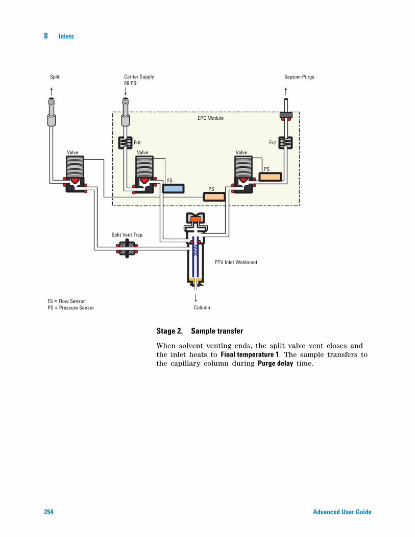
254 Advanced User Guide
8 Inlets
Stage 2. Sample transfer
When solvent venting ends, the split valve vent closes and the inlet heats to Final temperature 1. The sample transfers to the capillary column during Purge delay time.
Valve
Frit Frit
Valve
EPC Module
Valve
Split Vent Trap
PTV Inlet Weldment
FS = Flow SensorPS = Pressure Sensor
FSPS
PS
Split Carrier Supply80 PSI
Septum Purge
Column
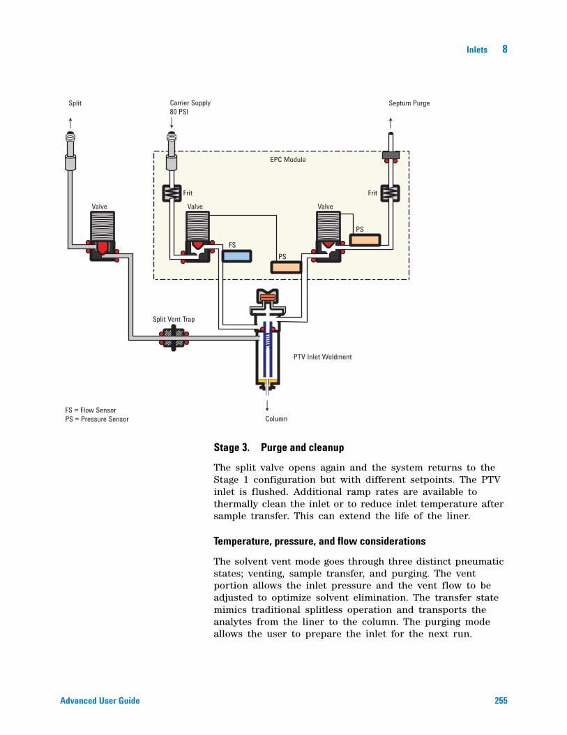
Inlets 8
Advanced User Guide 255
Stage 3. Purge and cleanup
The split valve opens again and the system returns to the Stage 1 configuration but with different setpoints. The PTV inlet is flushed. Additional ramp rates are available to thermally clean the inlet or to reduce inlet temperature after sample transfer. This can extend the life of the liner.
Temperature, pressure, and flow considerations
The solvent vent mode goes through three distinct pneumatic states; venting, sample transfer, and purging. The vent portion allows the inlet pressure and the vent flow to be adjusted to optimize solvent elimination. The transfer state mimics traditional splitless operation and transports the analytes from the liner to the column. The purging mode allows the user to prepare the inlet for the next run.
Valve
Frit Frit
Valve
EPC Module
Valve
Split Vent Trap
PTV Inlet Weldment
FS = Flow SensorPS = Pressure Sensor
FSPS
PS
Split Carrier Supply80 PSI
Septum Purge
Column
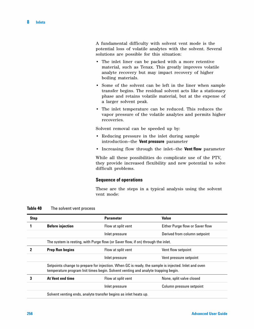
256 Advanced User Guide
8 Inlets
A fundamental difficulty with solvent vent mode is the potential loss of volatile analytes with the solvent. Several solutions are possible for this situation:
• The inlet liner can be packed with a more retentive material, such as Tenax. This greatly improves volatile analyte recovery but may impact recovery of higher boiling materials.
• Some of the solvent can be left in the liner when sample transfer begins. The residual solvent acts like a stationary phase and retains volatile material, but at the expense of a larger solvent peak.
• The inlet temperature can be reduced. This reduces the vapor pressure of the volatile analytes and permits higher recoveries.
Solvent removal can be speeded up by:
• Reducing pressure in the inlet during sample introduction—the Vent pressure parameter
• Increasing flow through the inlet—the Vent flow parameter
While all these possibilities do complicate use of the PTV, they provide increased flexibility and new potential to solve difficult problems.
Sequence of operations
These are the steps in a typical analysis using the solvent vent mode:
Table 40 The solvent vent process
Step Parameter Value
1 Before injection Flow at split vent Either Purge flow or Saver flow
Inlet pressure Derived from column setpoint
The system is resting, with Purge flow (or Saver flow, if on) through the inlet.
2 Prep Run begins Flow at split vent Vent flow setpoint
Inlet pressure Vent pressure setpoint
Setpoints change to prepare for injection. When GC is ready, the sample is injected. Inlet and oven temperature program Init times begin. Solvent venting and analyte trapping begin.
3 At Vent end time Flow at split vent None, split valve closed
Inlet pressure Column pressure setpoint
Solvent venting ends, analyte transfer begins as inlet heats up.
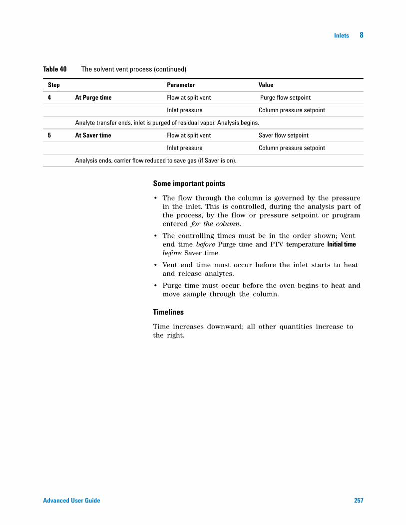
Inlets 8
Advanced User Guide 257
Some important points
• The flow through the column is governed by the pressure in the inlet. This is controlled, during the analysis part of the process, by the flow or pressure setpoint or program entered for the column.
• The controlling times must be in the order shown; Vent end time before Purge time and PTV temperature Initial time before Saver time.
• Vent end time must occur before the inlet starts to heat and release analytes.
• Purge time must occur before the oven begins to heat and move sample through the column.
Timelines
Time increases downward; all other quantities increase to the right.
4 At Purge time Flow at split vent Purge flow setpoint
Inlet pressure Column pressure setpoint
Analyte transfer ends, inlet is purged of residual vapor. Analysis begins.
5 At Saver time Flow at split vent Saver flow setpoint
Inlet pressure Column pressure setpoint
Analysis ends, carrier flow reduced to save gas (if Saver is on).
Table 40 The solvent vent process (continued)
Step Parameter Value
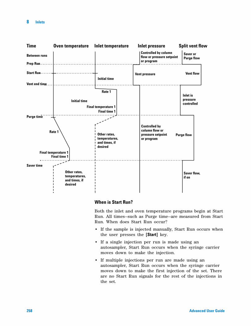
258 Advanced User Guide
8 Inlets
When is Start Run?
Both the inlet and oven temperature programs begin at Start Run. All times—such as Purge time—are measured from Start Run. When does Start Run occur?
• If the sample is injected manually, Start Run occurs when the user presses the [Start] key.
• If a single injection per run is made using an autosampler, Start Run occurs when the syringe carrier moves down to make the injection.
• If multiple injections per run are made using an autosampler, Start Run occurs when the syringe carrier moves down to make the first injection of the set. There are no Start Run signals for the rest of the injections in the set.
Time Oven temperature Inlet temperature Inlet pressure Split vent flow
Between runs
Prep Run
Start Run
Vent end time
Purge time
Saver time
Rate 1
Initial time
Final temperature 1Final time 1
Rate 1
Final temperature 1Final time 1
Other rates,temperatures,and times, ifdesired
Initial time
Other rates,temperatures,and times, ifdesired
Saver orPurge flow
Vent flow
Inlet ispressurecontrolled
Purge flow
Saver flow,if on
Controlled by columnflow or pressure setpointor program
Vent pressure
Controlled bycolumn flow orpressure setpointor program
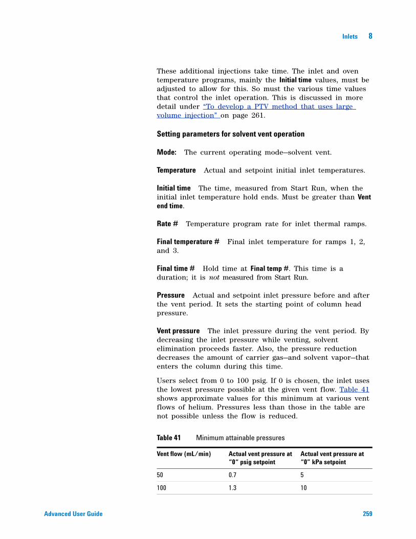
Inlets 8
Advanced User Guide 259
These additional injections take time. The inlet and oven temperature programs, mainly the Initial time values, must be adjusted to allow for this. So must the various time values that control the inlet operation. This is discussed in more detail under “To develop a PTV method that uses large volume injection” on page 261.
Setting parameters for solvent vent operation
Mode: The current operating mode—solvent vent.
Temperature Actual and setpoint initial inlet temperatures.
Initial time The time, measured from Start Run, when the initial inlet temperature hold ends. Must be greater than Vent end time.
Rate # Temperature program rate for inlet thermal ramps.
Final temperature # Final inlet temperature for ramps 1, 2, and 3.
Final time # Hold time at Final temp #. This time is a duration; it is not measured from Start Run.
Pressure Actual and setpoint inlet pressure before and after the vent period. It sets the starting point of column head pressure.
Vent pressure The inlet pressure during the vent period. By decreasing the inlet pressure while venting, solvent elimination proceeds faster. Also, the pressure reduction decreases the amount of carrier gas—and solvent vapor—that enters the column during this time.
Users select from 0 to 100 psig. If 0 is chosen, the inlet uses the lowest pressure possible at the given vent flow. Table 41 shows approximate values for this minimum at various vent flows of helium. Pressures less than those in the table are not possible unless the flow is reduced.
Table 41 Minimum attainable pressures
Vent flow (mL/min) Actual vent pressure at “0“ psig setpoint
Actual vent pressure at “0” kPa setpoint
50 0.7 5
100 1.3 10
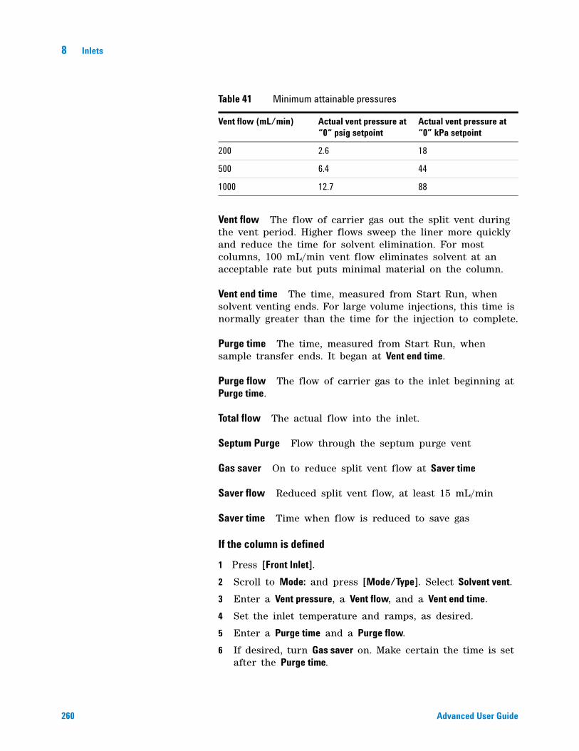
260 Advanced User Guide
8 Inlets
Vent flow The flow of carrier gas out the split vent during the vent period. Higher flows sweep the liner more quickly and reduce the time for solvent elimination. For most columns, 100 mL/min vent flow eliminates solvent at an acceptable rate but puts minimal material on the column.
Vent end time The time, measured from Start Run, when solvent venting ends. For large volume injections, this time is normally greater than the time for the injection to complete.
Purge time The time, measured from Start Run, when sample transfer ends. It began at Vent end time.
Purge flow The flow of carrier gas to the inlet beginning at Purge time.
Total flow The actual flow into the inlet.
Septum Purge Flow through the septum purge vent
Gas saver On to reduce split vent flow at Saver time
Saver flow Reduced split vent flow, at least 15 mL/min
Saver time Time when flow is reduced to save gas
If the column is defined
1 Press [Front Inlet].
2 Scroll to Mode: and press [Mode/Type]. Select Solvent vent.
3 Enter a Vent pressure, a Vent flow, and a Vent end time.
4 Set the inlet temperature and ramps, as desired.
5 Enter a Purge time and a Purge flow.
6 If desired, turn Gas saver on. Make certain the time is set after the Purge time.
200 2.6 18
500 6.4 44
1000 12.7 88
Table 41 Minimum attainable pressures
Vent flow (mL/min) Actual vent pressure at “0“ psig setpoint
Actual vent pressure at “0” kPa setpoint
Inlets 8
Advanced User Guide 261
7 Press [Prep Run] (see “Pre Run and Prep Run” on page 184) before manually injecting a sample.
If the column is not defined
1 Set up the parameters as described for the defined column case.
2 Set Total flow greater than the column flow plus the septum purge flow to guarantee adequate column flow.
To develop a PTV method that uses large volume injection
This topic provides a recommended way to change from a splitless injection using a split/splitless inlet to a solvent vent mode injection using a programmable temperature vaporization inlet (PTV). It applies mainly to large volume injections (LVI) using a PTV, but the concepts can apply to general PTV use. This topic does not consider all items that can impact an analysis, for example the liner, solvent, analyte boiling points, or polarity. This topic also assumes knowledge of your data system—when to save a method, how to start a run, how to set up a single run, etc.
The main advantage of the PTV inlet's solvent vent mode is that you can inject slowly into the inlet, allowing large amounts of solvent to evaporate in the liner (not in the split vent line). This concentrates the analytes prior to injection. It requires an injector with variable speed injections, a “large” syringe, and knowledge of the sample and the solvent.
When developing a solvent vent method, the goal is to determine the injection rates and temperatures needed to evaporate the solvent at the rate it enters the inlet. The development technique is to gradually scale up to an injection amount that produces a useful response. The most significant parameters are:
Temperature Hold the inlet temperature at or slightly below the solvent boiling point until after all the sample has been injected. This is important so that you do not boil away more volatile analytes, or boil away the solvent in the needle and trap your analytes there. An additional point to consider is that the boiling point of the earliest eluting analyte should be 100 °C less than the boiling point of the solvent.
262 Advanced User Guide
8 Inlets
Injection speed Estimate the evaporation rate of solvent exiting the needle based on solvent type, inlet temperature, vent flow, and pressure. Start with about half that number. Note that you have to make sure that you configure the syringe properly. If not, you will over- or under- load the inlet.
Vent end time The vent end time setpoint must be greater than the time the needle spends in the inlet. If the vent time is too short, you will overload and contaminate the column and inlet. Adjust the vent time as you scale up the method.
If using a PTV with an MSD, another tip for method development is to scan for solvent ions. Detecting the solvent ions can be useful in troubleshooting residual solvent bleed onto the column.
To develop a PTV method for large volume injection, try the following:
1 Determine a small injection volume that works on a split/splitless inlet in splitless mode or the PTV in splitless mode. Choose a volume that does not currently overload the inlet.
2 Start with a 5–10 uL syringe and make sure the syringe is properly configured in the instrument and data system.
3 Make sure the column is configured.
4 Set up the inlet to perform a 1 uL injection.
Use the splitless method conditions, except:
• Start with the inlet temperature cold, near but slightly below the solvent boiling point. For example, if using methylene chloride (boiling point 39 °C), start with a temperature of 30–39 °C.
• Use Splitless mode.
• Ramp to the normal splitless inlet temperature.
5 Note the response achieved.
6 Next, change the inlet mode to Solvent vent.
7 Check the injector timings.
a Install an empty sample vial in the injector turret or tray.
b Input the injection rate (Sample Draw Speed, Sample Disp Speed, and Inject Dispense Speed rates) for the injector and increase the injection volume to 5 uL.
c Enter draft Solvent vent parameters:
Inlets 8
Advanced User Guide 263
• Set a Vent flow of 100 mL/min as a starting point.
• Keep the inlet isothermal for now.
• Enter a Vent pressure of 0 psi (0 kPa) and Vent end time of 0.1 minutes.
d Make an injection using the empty vial. Use a stopwatch or your GC's timer feature to time how long the needle is in the inlet.
8 Enter revised Solvent vent mode parameters.
• Set the method's Vent end time to be about 0.05 min longer than the time the needle spends in the inlet.
• Set the inlet temperature Initial time to be about 0.05 min longer than the Vent pressure time.
• Program the inlet to ramp quickly to the injection temperature. Make sure the ramp starts after the Vent end time.
• Set the Purge Flow to 30 mL/min. Set the purge time to be the vent pressure Vent end time + 1 minute.
9 Make a 5 uL injection of your standard. You should see 5 times the response.
If the response of all analytes is too low:
• The dispense speed is too fast. Liquid was injected into the inlet and pushed out the vent.
• The vent time is too long. The inlet started to heat while the vent was open.
If the response of early eluters is too low:
• The inlet temperature is too high.
• The Vent flow is too high.
If the response of late eluters is too low:
• The purge time is too short.
• The final inlet temperature is too low.
10 If you need more injection volume and the 5 uL worked to give 5 times the response, change the syringe to a larger one, for example, 50 uL.
11 Set up the data system to perform a 25 uL injection.
12 Configure the syringe. Make sure the plunger speeds on the injector are still set properly.
13 Recheck the injector timings. See the step above.
264 Advanced User Guide
8 Inlets
14 Set a new vent time and initial inlet temperature time based on the new time the needle spends in the syringe.
15 Make a 25 uL injection of your standard. Again, you should see 5 times the response. If not, see step 13.
16 If you need more response, repeat steps 10 through 15 to increase to larger volume. See the next section. Try performing 5 x 5 uL injections, then 5 x 50 uL injections.
Multiple injections with the PTV inlet
The preferred technique for concentrating analytes in the inlet liner is to use a single, large volume injection. Using a high capacity syringe and one septum puncture reduces the possibility of contamination and generally improves results when compared against a multiple septum puncture technique. However, if needed, you can perform multiple septum punctures during the vent time. This technique requires an Agilent data system and automatic liquid sampler.
Data system requirements
An Agilent data system is necessary for multiple injection because the needed parameters are not available through the GC keyboard.
GC ChemStation Software revision B.04.01 SP1 or later.
MSD ChemStation Software revision E.02.00 SP2 or later
EZChrom Software revision 3.3.2 or later
Setting parameters for the inlet in solvent vent mode
Set or configure the following parameters in the data system's 7890A GC method editor.
Syringe size — Verify the syringe size is configured correctly. The configured syringe size changes the available choices for injection volume.
Injection volume — Select the injection volume, then enter a number of injections. The total injection volume will be displayed.
Multiple Injection Delay — A pause time, in seconds, between injections. This is added to the minimum hardware cycle time.
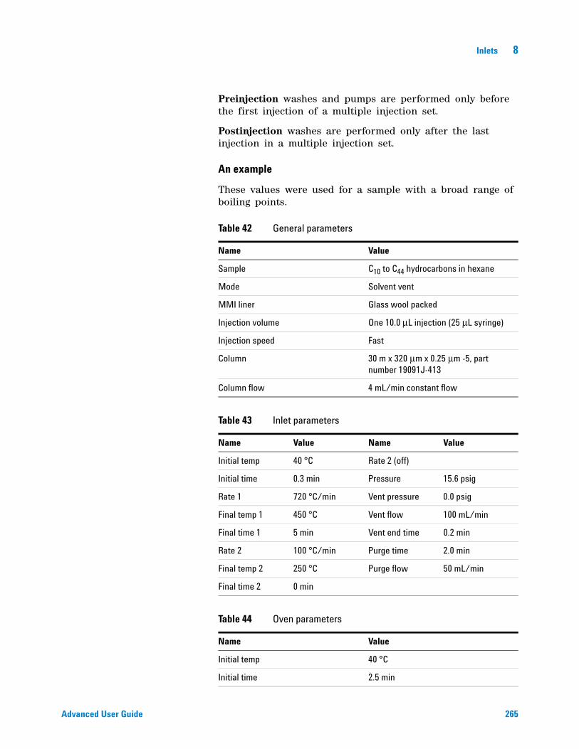
Inlets 8
Advanced User Guide 265
Preinjection washes and pumps are performed only before the first injection of a multiple injection set.
Postinjection washes are performed only after the last injection in a multiple injection set.
An example
These values were used for a sample with a broad range of boiling points.
Table 42 General parameters
Name Value
Sample C10 to C44 hydrocarbons in hexane
Mode Solvent vent
MMI liner Glass wool packed
Injection volume One 10.0 μL injection (25 μL syringe)
Injection speed Fast
Column 30 m x 320 μm x 0.25 μm -5, part number 19091J-413
Column flow 4 mL/min constant flow
Table 43 Inlet parameters
Name Value Name Value
Initial temp 40 °C Rate 2 (off)
Initial time 0.3 min Pressure 15.6 psig
Rate 1 720 °C/min Vent pressure 0.0 psig
Final temp 1 450 °C Vent flow 100 mL/min
Final time 1 5 min Vent end time 0.2 min
Rate 2 100 °C/min Purge time 2.0 min
Final temp 2 250 °C Purge flow 50 mL/min
Final time 2 0 min
Table 44 Oven parameters
Name Value
Initial temp 40 °C
Initial time 2.5 min
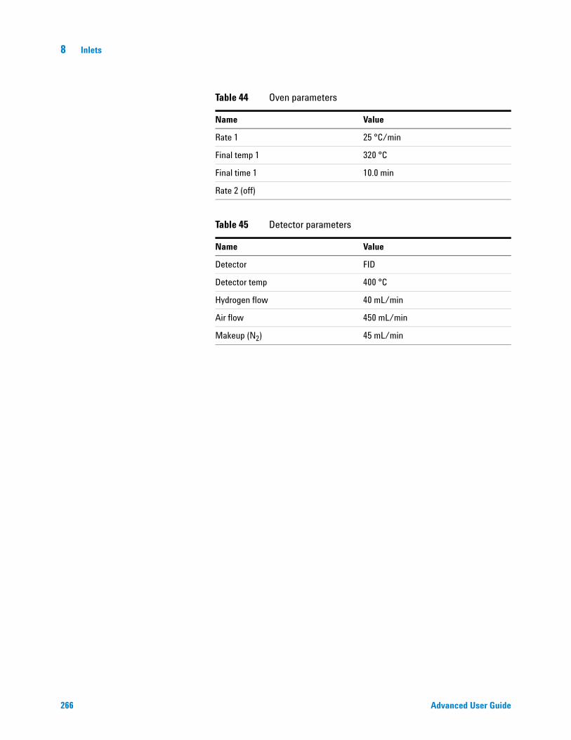
266 Advanced User Guide
8 Inlets
Rate 1 25 °C/min
Final temp 1 320 °C
Final time 1 10.0 min
Rate 2 (off)
Table 45 Detector parameters
Name Value
Detector FID
Detector temp 400 °C
Hydrogen flow 40 mL/min
Air flow 450 mL/min
Makeup (N2) 45 mL/min
Table 44 Oven parameters
Name Value

Inlets 8
Advanced User Guide 267
These results were compared with a splitless analysis of the same sample, which should produce 100% recovery of all analytes. The data showed that, under these conditions, compounds above C20 were completely recovered and that the recovery was independent of injection size. Compounds lower than C20 were partially vented with the solvent.
Possible adjustments
Depending on what you are trying to accomplish, you have a number of possible adjustments available.
To eliminate more solvent
• Increase the vent end time, inlet initial time, and purge time. This will not affect analytes that are quantitatively trapped but will eliminate more of the solvent peak.
• Increase the vent flow to sweep the liner more rapidly with the same inlet timing. Increasing vent flow raises vent pressure if it is set to 0. This puts more solvent onto the column.
C20

268 Advanced User Guide
8 Inlets
• Raise the inlet initial temperature to vaporize more solvent and allow more to be eliminated. This also increases the loss of volatile analytes since their vapor pressures also increase.
To improve recovery of low boiling analytes
• Reduce inlet temperature to lower the vapor pressure of the analytes and trap them more effectively. This also reduces solvent vapor pressure and more time will be needed to eliminate it.
• Use a retentive packing in the liner. Materials such as Tenax permit higher recovery of volatile analytes but may not release higher boiling compounds. This must be considered if quantitation on these high boiling peaks is desired.
• Leave more solvent in the liner. The solvent acts as a pseudo stationary phase and helps retain volatile analytes. This must be balanced against the detector’s tolerance for solvent.
An example—continued
The single injection example shown on the last few pages makes it clear that a 10 μL injection does not overload the glass wool packed liner. This means that multiple 10 μL injections are possible.
It was decided to make 10 injections per run, each of 10 μL size. This would increase analytical sensitivity substantially. No adjustments were made to improve recovery of the low boilers since the purpose of this analysis was to detect and measure the high boiling components.
After timing a trial set of 10 injections, the total time for the multiple injection set was measured to be approximately 1.3 minutes. The following timing changes were made:
Table 46 Modifications
Parameter Increased from To
Inlet Init time 0.3 minutes 1.6 minutes
Vent end time 0.2 minutes 1.5 minutes
Purge time 2.0 minutes 3.0 minutes
Oven Init time 2.5 minutes 3.0 minutes

Inlets 8
Advanced User Guide 269
The result is shown in the next figure. Note the difference in the vertical scale (5000 versus 500).
C20
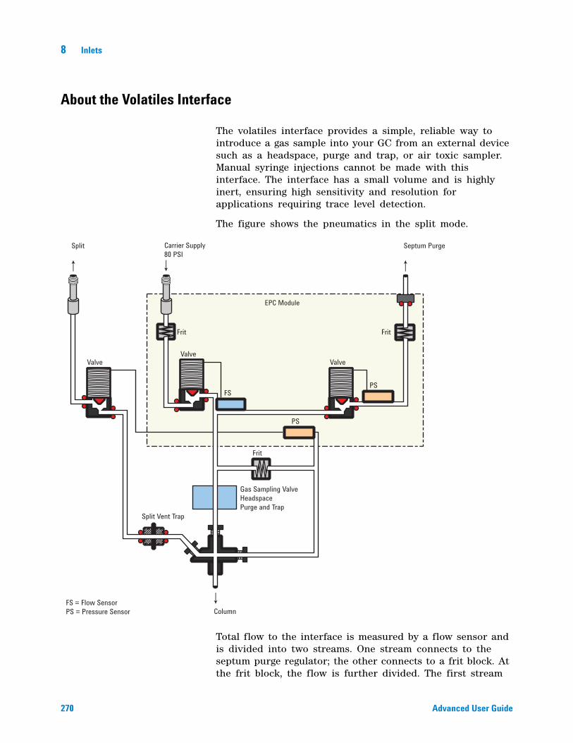
270 Advanced User Guide
8 Inlets
About the Volatiles Interface
The volatiles interface provides a simple, reliable way to introduce a gas sample into your GC from an external device such as a headspace, purge and trap, or air toxic sampler. Manual syringe injections cannot be made with this interface. The interface has a small volume and is highly inert, ensuring high sensitivity and resolution for applications requiring trace level detection.
The figure shows the pneumatics in the split mode.
Total flow to the interface is measured by a flow sensor and is divided into two streams. One stream connects to the septum purge regulator; the other connects to a frit block. At the frit block, the flow is further divided. The first stream
Valve
Frit Frit
Frit
Valve
EPC Module
Valve
Split Vent Trap
Gas Sampling ValveHeadspacePurge and Trap
FS = Flow SensorPS = Pressure Sensor Column
FS
PS
PS
Split Carrier Supply80 PSI
Septum Purge
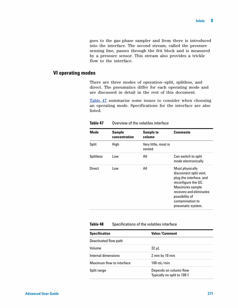
Inlets 8
Advanced User Guide 271
goes to the gas- phase sampler and from there is introduced into the interface. The second stream, called the pressure sensing line, passes through the frit block and is measured by a pressure sensor. This stream also provides a trickle flow to the interface.
VI operating modes
There are three modes of operation—split, splitless, and direct. The pneumatics differ for each operating mode and are discussed in detail in the rest of this document.
Table 47 summarize some issues to consider when choosing an operating mode. Specifications for the interface are also listed.
Table 47 Overview of the volatiles interface
Mode Sample concentration
Sample to column
Comments
Split High Very little, most is vented
Splitless Low All Can switch to split mode electronically.
Direct Low All Must physically disconnect split vent, plug the interface, and reconfigure the GC. Maximizes sample recovery and eliminates possibility of contamination to pneumatic system.
Table 48 Specifications of the volatiles interface
Specification Value/Comment
Deactivated flow path
Volume 32 µL
Internal dimensions 2 mm by 10 mm
Maximum flow to interface 100 mL/min
Split range Depends on column flow Typically no split to 100:1
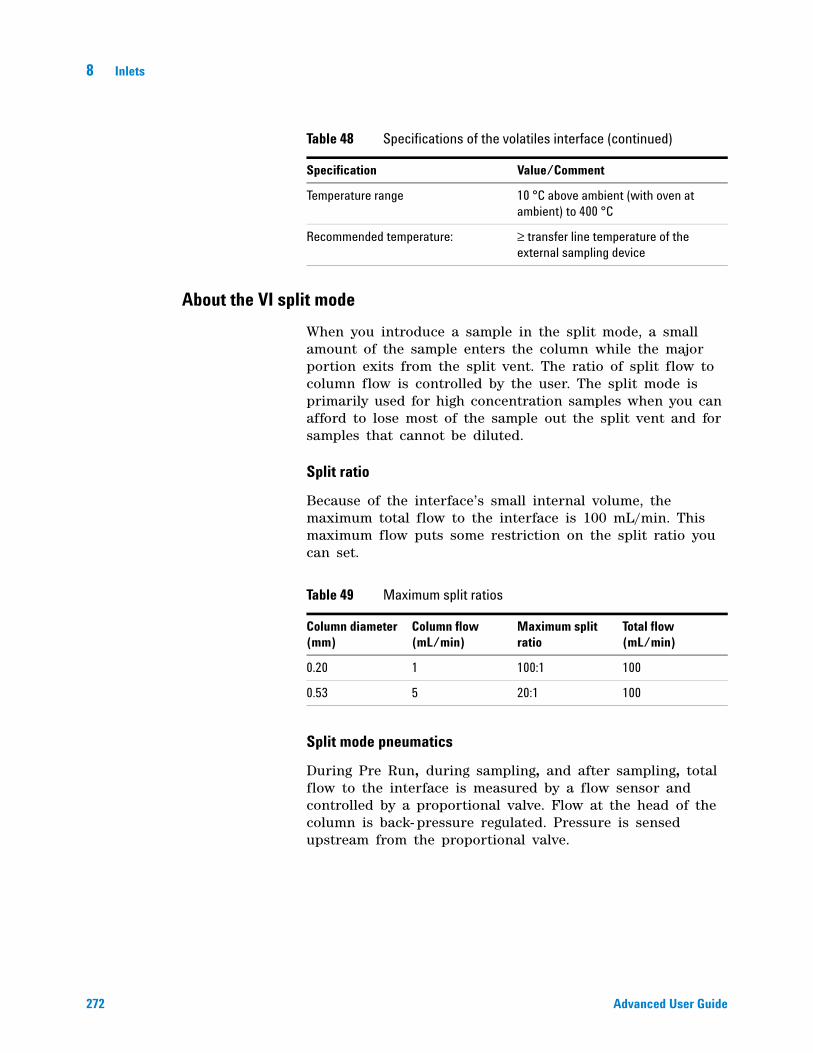
272 Advanced User Guide
8 Inlets
About the VI split mode
When you introduce a sample in the split mode, a small amount of the sample enters the column while the major portion exits from the split vent. The ratio of split flow to column flow is controlled by the user. The split mode is primarily used for high concentration samples when you can afford to lose most of the sample out the split vent and for samples that cannot be diluted.
Split ratio
Because of the interface’s small internal volume, the maximum total flow to the interface is 100 mL/min. This maximum flow puts some restriction on the split ratio you can set.
Split mode pneumatics
During Pre Run, during sampling, and after sampling, total flow to the interface is measured by a flow sensor and controlled by a proportional valve. Flow at the head of the column is back- pressure regulated. Pressure is sensed upstream from the proportional valve.
Temperature range 10 °C above ambient (with oven at ambient) to 400 °C
Recommended temperature: ≥ transfer line temperature of the external sampling device
Table 48 Specifications of the volatiles interface (continued)
Specification Value/Comment
Table 49 Maximum split ratios
Column diameter (mm)
Column flow (mL/min)
Maximum split ratio
Total flow (mL/min)
0.20 1 100:1 100
0.53 5 20:1 100
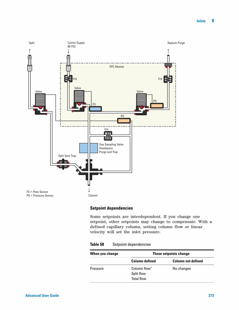
Inlets 8
Advanced User Guide 273
Setpoint dependencies
Some setpoints are interdependent. If you change one setpoint, other setpoints may change to compensate. With a defined capillary column, setting column flow or linear velocity will set the inlet pressure.
Valve
Frit Frit
Frit
Valve
EPC Module
Valve
Split Vent Trap
Gas Sampling ValveHeadspacePurge and Trap
FS = Flow SensorPS = Pressure Sensor Column
FS
PS
PS
Split Carrier Supply80 PSI
Septum Purge
Table 50 Setpoint dependencies
When you change These setpoints change
Column defined Column not defined
Pressure Column flow*Split flowTotal flow
No changes
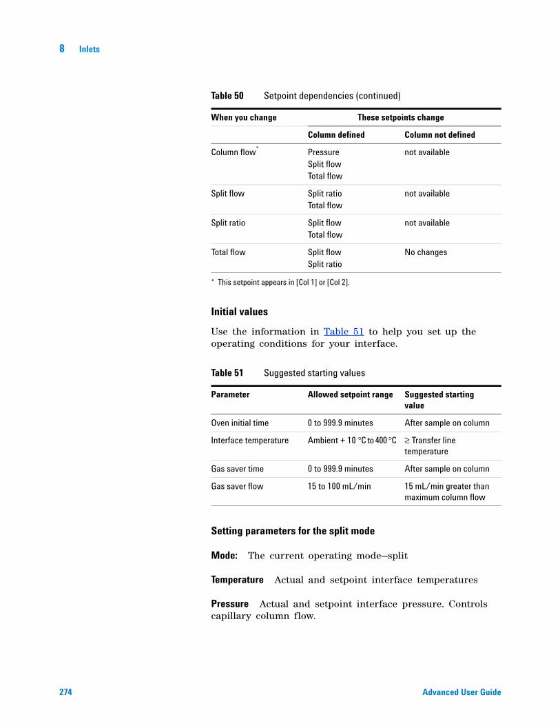
274 Advanced User Guide
8 Inlets
Initial values
Use the information in Table 51 to help you set up the operating conditions for your interface.
Setting parameters for the split mode
Mode: The current operating mode—split
Temperature Actual and setpoint interface temperatures
Pressure Actual and setpoint interface pressure. Controls capillary column flow.
Column flow* PressureSplit flowTotal flow
not available
Split flow Split ratioTotal flow
not available
Split ratio Split flowTotal flow
not available
Total flow Split flowSplit ratio
No changes
* This setpoint appears in [Col 1] or [Col 2].
Table 51 Suggested starting values
Parameter Allowed setpoint range Suggested starting value
Oven initial time 0 to 999.9 minutes After sample on column
Interface temperature Ambient + 10 °C to 400 °C ≥ Transfer line temperature
Gas saver time 0 to 999.9 minutes After sample on column
Gas saver flow 15 to 100 mL/min 15 mL/min greater than maximum column flow
Table 50 Setpoint dependencies (continued)
When you change These setpoints change
Column defined Column not defined
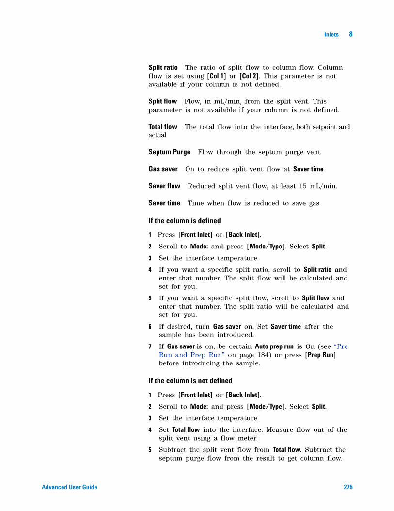
Inlets 8
Advanced User Guide 275
Split ratio The ratio of split flow to column flow. Column flow is set using [Col 1] or [Col 2]. This parameter is not available if your column is not defined.
Split flow Flow, in mL/min, from the split vent. This parameter is not available if your column is not defined.
Total flow The total flow into the interface, both setpoint and actual
Septum Purge Flow through the septum purge vent
Gas saver On to reduce split vent flow at Saver time
Saver flow Reduced split vent flow, at least 15 mL/min.
Saver time Time when flow is reduced to save gas
If the column is defined
1 Press [Front Inlet] or [Back Inlet].
2 Scroll to Mode: and press [Mode/Type]. Select Split.
3 Set the interface temperature.
4 If you want a specific split ratio, scroll to Split ratio and enter that number. The split flow will be calculated and set for you.
5 If you want a specific split flow, scroll to Split flow and enter that number. The split ratio will be calculated and set for you.
6 If desired, turn Gas saver on. Set Saver time after the sample has been introduced.
7 If Gas saver is on, be certain Auto prep run is On (see “Pre Run and Prep Run” on page 184) or press [Prep Run] before introducing the sample.
If the column is not defined
1 Press [Front Inlet] or [Back Inlet].
2 Scroll to Mode: and press [Mode/Type]. Select Split.
3 Set the interface temperature.
4 Set Total flow into the interface. Measure flow out of the split vent using a flow meter.
5 Subtract the split vent flow from Total flow. Subtract the septum purge flow from the result to get column flow.
276 Advanced User Guide
8 Inlets
6 Calculate the split ratio (split vent flow/column flow). Adjust as needed.
7 If desired, turn Gas saver on. Set Saver time after the sample has been introduced.
8 If Gas saver is on, be certain Auto prep run is On (see “Pre Run and Prep Run” on page 184) or press [Prep Run] before introducing the sample.
About the VI splitless mode
This mode is used to concentrate sample at the head of the GC column during desorb. Purge timing delay must take into consideration the volume of the loop or trap in the external sampler plus the transfer line versus desorb/total flow rate. Cryo focussing is required for very volatile samples in splitless mode.
When you introduce a sample, the split valve remains closed while the sample enters the interface and is transferred to the column. At a specified time after the sample is introduced, the split valve opens.
Splitless mode pneumatics
Before Pre Run When the GC is preparing for sample introduction, total flow to the interface is measured by a flow sensor and controlled by a proportional valve. Column flow is controlled via back- pressure regulation. The split valve is open.
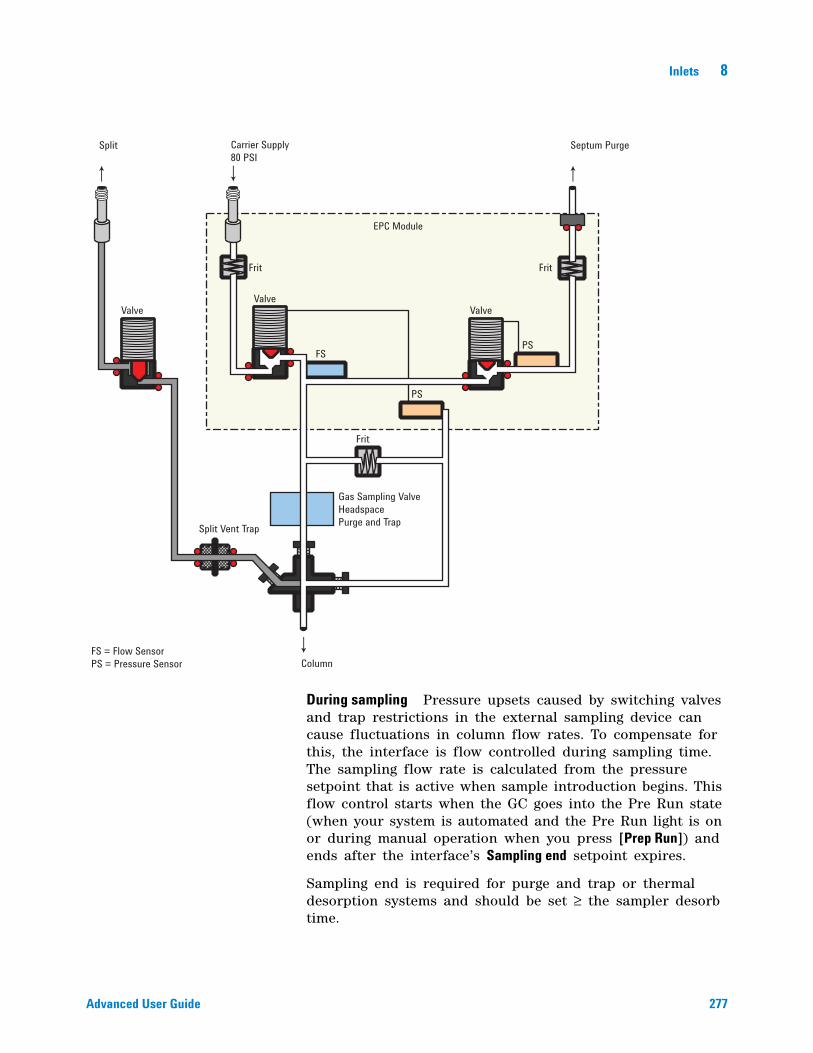
Inlets 8
Advanced User Guide 277
During sampling Pressure upsets caused by switching valves and trap restrictions in the external sampling device can cause fluctuations in column flow rates. To compensate for this, the interface is flow controlled during sampling time. The sampling flow rate is calculated from the pressure setpoint that is active when sample introduction begins. This flow control starts when the GC goes into the Pre Run state (when your system is automated and the Pre Run light is on or during manual operation when you press [Prep Run]) and ends after the interface’s Sampling end setpoint expires.
Sampling end is required for purge and trap or thermal desorption systems and should be set ≥ the sampler desorb time.
Valve
Frit Frit
Frit
Valve
EPC Module
Valve
Split Vent Trap
Gas Sampling ValveHeadspacePurge and Trap
FS = Flow SensorPS = Pressure Sensor Column
FS
PS
PS
Split Carrier Supply80 PSI
Septum Purge
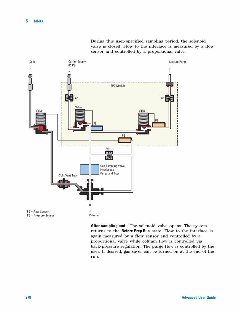
278 Advanced User Guide
8 Inlets
During this user- specified sampling period, the solenoid valve is closed. Flow to the interface is measured by a flow sensor and controlled by a proportional valve.
After sampling end The solenoid valve opens. The system returns to the Before Prep Run state. Flow to the interface is again measured by a flow sensor and controlled by a proportional valve while column flow is controlled via back- pressure regulation. The purge flow is controlled by the user. If desired, gas saver can be turned on at the end of the run.
Valve
Frit Frit
Frit
Valve
EPC Module
Valve
Split Vent Trap
Gas Sampling ValveHeadspacePurge and Trap
FS = Flow SensorPS = Pressure Sensor Column
FS
PS
PS
Split Carrier Supply80 PSI
Septum Purge
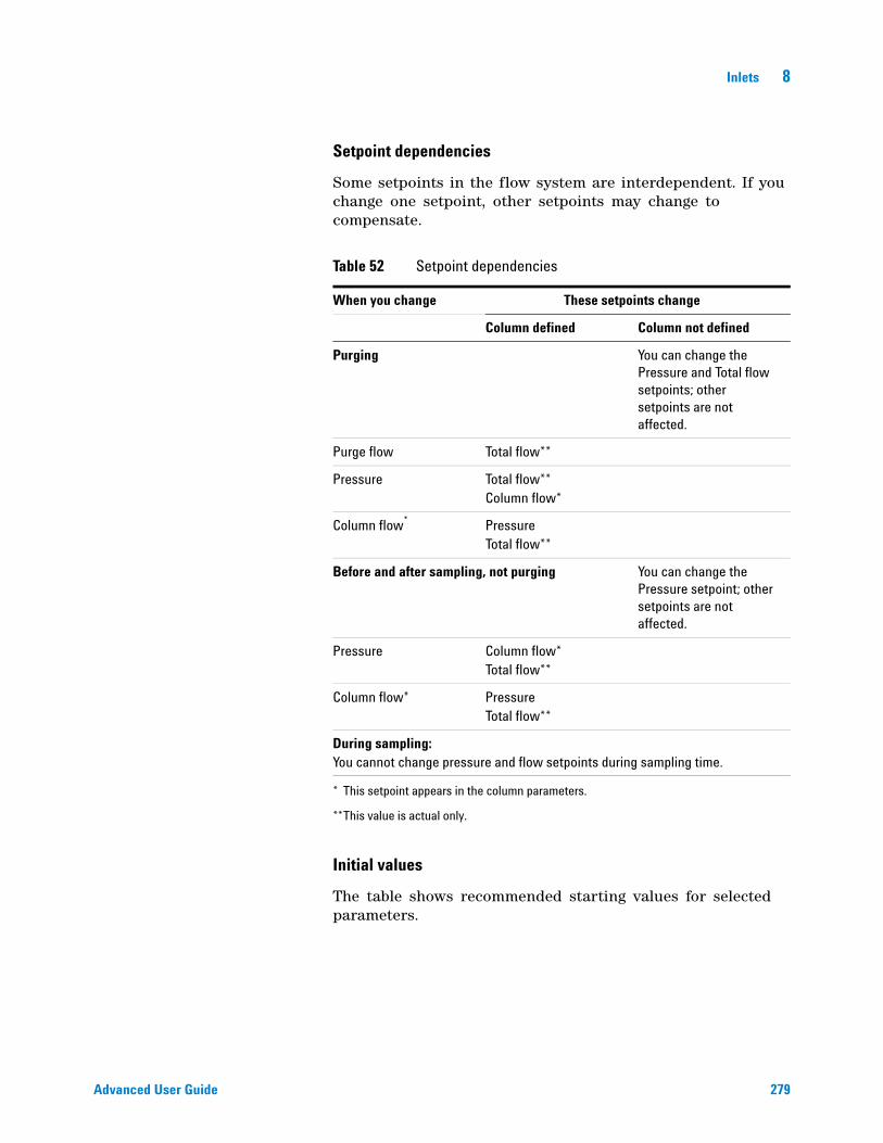
Inlets 8
Advanced User Guide 279
Setpoint dependencies
Some setpoints in the flow system are interdependent. If you change one setpoint, other setpoints may change to compensate.
Initial values
The table shows recommended starting values for selected parameters.
Table 52 Setpoint dependencies
When you change These setpoints change
Column defined Column not defined
Purging You can change the Pressure and Total flow setpoints; other setpoints are not affected.
Purge flow Total flow**
Pressure Total flow**Column flow*
Column flow*
* This setpoint appears in the column parameters.
**This value is actual only.
PressureTotal flow**
Before and after sampling, not purging You can change the Pressure setpoint; other setpoints are not affected.
Pressure Column flow*Total flow**
Column flow* PressureTotal flow**
During sampling:You cannot change pressure and flow setpoints during sampling time.
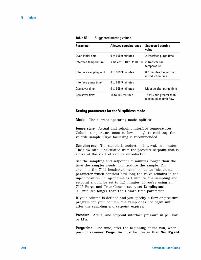
280 Advanced User Guide
8 Inlets
Setting parameters for the VI splitless mode
Mode: The current operating mode—splitless
Temperature Actual and setpoint interface temperatures. Column temperature must be low enough to cold trap the volatile sample. Cryo focussing is recommended.
Sampling end The sample introduction interval, in minutes. The flow rate is calculated from the pressure setpoint that is active at the start of sample introduction.
Set the sampling end setpoint 0.2 minutes longer than the time the sampler needs to introduce the sample. For example, the 7694 headspace sampler has an Inject time parameter which controls how long the valve remains in the inject position. If Inject time is 1 minute, the sampling end setpoint should be set to 1.2 minutes. If you’re using an 7695 Purge and Trap Concentrator, set Sampling end 0.2 minutes longer than the Desorb time parameter.
If your column is defined and you specify a flow or pressure program for your column, the ramp does not begin until after the sampling end setpoint expires.
Pressure Actual and setpoint interface pressure in psi, bar, or kPa.
Purge time The time, after the beginning of the run, when purging resumes. Purge time must be greater than Sampl’g end.
Table 53 Suggested starting values
Parameter Allowed setpoint range Suggested starting value
Oven initial time 0 to 999.9 minutes ≥ Interface purge time
Interface temperature Ambient + 10 °C to 400 °C ≥ Transfer line temperature
Interface sampling end 0 to 999.9 minutes 0.2 minutes longer than introduction time
Interface purge time 0 to 999.9 minutes
Gas saver time 0 to 999.9 minutes Must be after purge time
Gas saver flow 15 to 100 mL/min 15 mL/min greater than maximum column flow
Inlets 8
Advanced User Guide 281
Purge flow The flow, in mL/min, from the split vent at Purge time. You will not be able to access or specify this value if your column is not defined.
Total flow When your column is defined, Total flow displays the actual flow to the interface. You cannot enter a setpoint. If your column is not defined, Total flow will have both setpoint and actual values during purge time. All other times, the actual flow to the interface is displayed.
Septum Purge Flow through the septum purge vent, at least 15 mL/min.
Gas saver On to reduce split vent flow at Saver time.
Saver flow Flow through the split vent after Saver time.
These instructions apply to both column defined and not defined.
1 Press [Front Inlet] or [Back Inlet].
2 Scroll to Mode: and press [Mode/Type]. Select Splitless.
3 Set the interface temperature and a sampling end time.
4 If your column is defined, enter a Purge time and Purge flow. Turn Gas saver on if desired. Set the Gas saver time after the purge time and enter a Gas saver flow.
5 If your column is not defined, enter a Purge time (Purge flow is not available). Set Total flow greater than column flow plus septum purge flow to guarantee adequate column flow.
6 Make certain Auto Prep Run is On (see “Pre Run and Prep Run” on page 184) or press [Prep Run] before introducing a sample.
About the VI direct mode
Direct sample introduction permits a quantitative transfer of analyte without risking contamination to the pneumatic system. It provides the sensitivity required for air toxic analyses. The interface’s minimal dead volume also eliminates the potential interaction of solutes with poorly swept, active surfaces.
To operate in the direct mode, you must physically disconnect the split vent and reconfigure the GC.
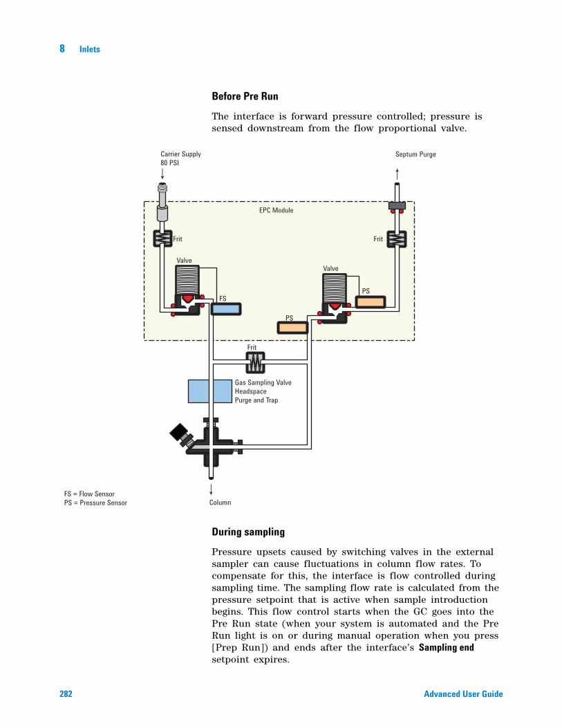
282 Advanced User Guide
8 Inlets
Before Pre Run
The interface is forward pressure controlled; pressure is sensed downstream from the flow proportional valve.
During sampling
Pressure upsets caused by switching valves in the external sampler can cause fluctuations in column flow rates. To compensate for this, the interface is flow controlled during sampling time. The sampling flow rate is calculated from the pressure setpoint that is active when sample introduction begins. This flow control starts when the GC goes into the Pre Run state (when your system is automated and the Pre Run light is on or during manual operation when you press [Prep Run]) and ends after the interface’s Sampling end setpoint expires.
Valve
Frit Frit
Frit
Valve
EPC Module
FS = Flow SensorPS = Pressure Sensor Column
FS
PS
PS
Carrier Supply80 PSI
Septum Purge
Gas Sampling ValveHeadspacePurge and Trap
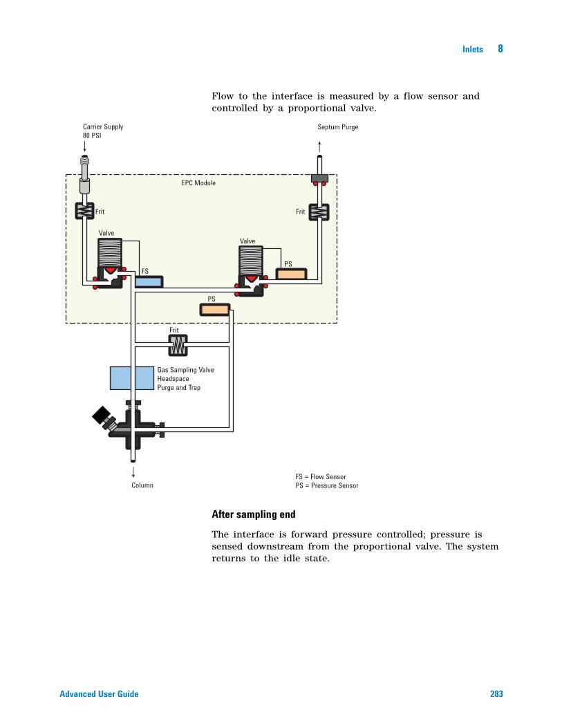
Inlets 8
Advanced User Guide 283
Flow to the interface is measured by a flow sensor and controlled by a proportional valve.
After sampling end
The interface is forward pressure controlled; pressure is sensed downstream from the proportional valve. The system returns to the idle state.
Valve
Frit Frit
Frit
Valve
EPC Module
Gas Sampling ValveHeadspacePurge and Trap
FS = Flow SensorPS = Pressure SensorColumn
FS
PS
PS
Carrier Supply80 PSI
Septum Purge
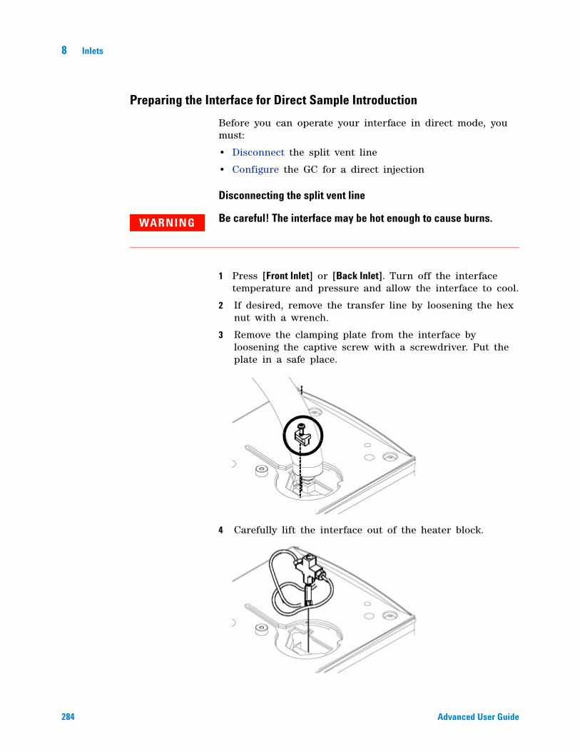
284 Advanced User Guide
8 Inlets
Preparing the Interface for Direct Sample Introduction
Before you can operate your interface in direct mode, you must:
• Disconnect the split vent line
• Configure the GC for a direct injection
Disconnecting the split vent line
1 Press [Front Inlet] or [Back Inlet]. Turn off the interface temperature and pressure and allow the interface to cool.
2 If desired, remove the transfer line by loosening the hex nut with a wrench.
3 Remove the clamping plate from the interface by loosening the captive screw with a screwdriver. Put the plate in a safe place.
4 Carefully lift the interface out of the heater block.
WARNING Be careful! The interface may be hot enough to cause burns.
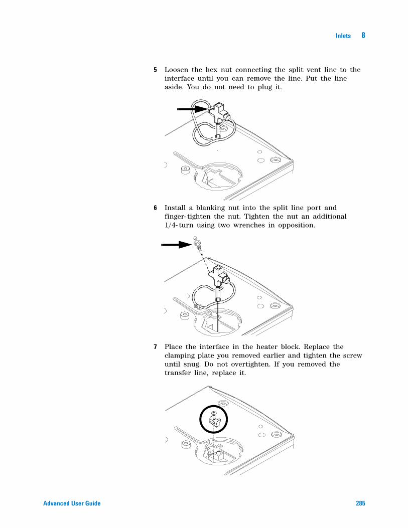
Inlets 8
Advanced User Guide 285
5 Loosen the hex nut connecting the split vent line to the interface until you can remove the line. Put the line aside. You do not need to plug it.
6 Install a blanking nut into the split line port and finger- tighten the nut. Tighten the nut an additional 1/4- turn using two wrenches in opposition.
7 Place the interface in the heater block. Replace the clamping plate you removed earlier and tighten the screw until snug. Do not overtighten. If you removed the transfer line, replace it.
286 Advanced User Guide
8 Inlets
8 Restore the GC to normal operating conditions. Perform a leak test on the interface fittings.
Configuring the GC for a direct injection
The GC cannot sense the presence of the split vent. When you disconnect or reconnect the vent, you must configure the GC so that the pneumatics work properly.
1 Press [Config][Back Inlet] or [Config][Front Inlet].
2 Scroll to Mode and press [Mode/Type].
3 Select Split vent removed. Press [Enter].
4 Press [Back Inlet] or [Front Inlet]. If the inlet is correctly configured, you will see the Direct injection display.
VI direct mode setpoint dependencies
Some setpoints in the flow system are interdependent. If you change one setpoint, other setpoints may change to compensate.
VI direct mode initial values
Use the information in Table 55 to help you set up the operating conditions for your interface.
Table 54 Setpoint changes
When you change These setpoints change
Column defined Column not defined
Before and after sampling
The Column flow* setpoint is not available.
Pressure Column flow*
Total flow**
* This setpoint appears in the column parameters
.**This value is actual only
You can change the pressure setpoint; other setpoints are not affected.
Column flow* PressureTotal flow**
During sampling You cannot change pressure and flow setpoints during sampling time.
Inlets 8
Advanced User Guide 287
Setting parameters for the VI direct mode
Temperature Actual and setpoint interface temperatures
Sampling end The sample introduction interval, in minutes. The flow rate is calculated from the pressure setpoint that is active at the start of sample introduction.
Set Sampling end 0.2 minutes longer than the time the sampler needs to introduce the sample. For example, the 7694 headspace sampler has an Inject time parameter which controls how long the valve remains in the inject position. If Inject time is 1 minute, Sampling end should be set to 1.2 minutes. If you’re using a 7695 Purge and Trap Concentrator, set Sampling end 0.2 minutes longer than the Desorb time parameter.
If your column is defined and you specify a flow or pressure program for your column, the ramp does not begin until after Sampling end expires.
Pressure Actual and setpoint interface pressure before a run and after sampling time.
Total flow The actual flow to the interface. This is a reported value, not a setpoint.
Septum Purge Flow through the septum purge vent, range 0 to 30 mL/min.
These instructions apply to both column defined and column not defined.
1 Press [Front Inlet] or [Back Inlet].
2 Confirm that your GC is configured for direct injection.
3 Set the interface temperature.
Table 55 Suggested starting values
Parameter Allowed setpoint range Suggested starting value
Oven initial time 0 to 999.9 minutes ≥ interface sampling end
Interface temperature Ambient + 10 °C to 400 °C
≥ transfer line temperature
Interface sampling end 0 to 999.9 minutes 0.2 minutes longer than actual sampling time

288 Advanced User Guide
8 Inlets
4 Set Sampling end at 0.2 minutes longer than the sample introduction time.
5 Make certain Auto Prep Run is On (see “Pre Run and Prep Run” on page 184) or press [Prep Run] before introducing a sample.
289
Agilent 7890A Gas ChromatographAdvanced User Guide
Agilent Technologies
9Columns and Oven
About the Oven 290
Oven safety 290
Configuring the Oven 291
Cryogenic Operation 292
Cryogenic setpoints 292
About Oven Temperature Programming 294
Programming setpoints 294
Oven ramp rates 295
Setting the oven parameters for constant temperature 296
Setting the oven parameters for ramped temperature 296
About the Oven Insert 298
Selecting the correct packed glass column type 299
About the column modes 299
Select a column mode 300
Setting the column parameters for constant flow or constant pressure 301
Enter a flow or pressure program (optional) 301
Programming column pressure or flow 302
About Columns 299
Backflushing a Column 303
Backflushing when connected to an MSD 304
Nickel Catalyst Tube 309
About the nickel catalyst tube 309
Nickel catalyst gas flows 309
Setting temperatures for the nickel catalyst tube 310
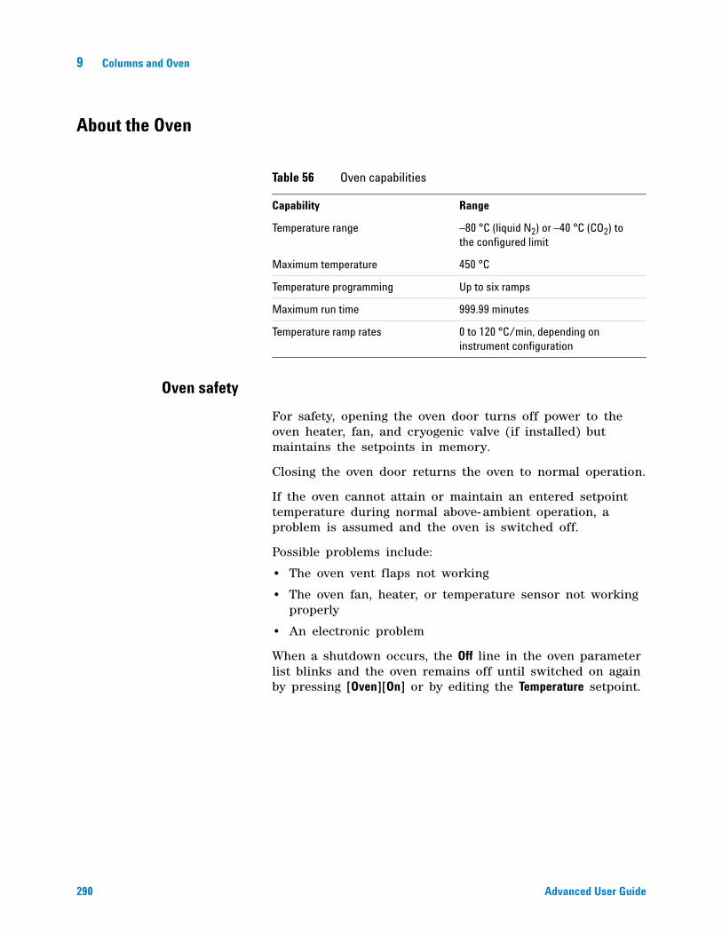
290 Advanced User Guide
9 Columns and Oven
About the Oven
Oven safety
For safety, opening the oven door turns off power to the oven heater, fan, and cryogenic valve (if installed) but maintains the setpoints in memory.
Closing the oven door returns the oven to normal operation.
If the oven cannot attain or maintain an entered setpoint temperature during normal above- ambient operation, a problem is assumed and the oven is switched off.
Possible problems include:
• The oven vent flaps not working
• The oven fan, heater, or temperature sensor not working properly
• An electronic problem
When a shutdown occurs, the Off line in the oven parameter list blinks and the oven remains off until switched on again by pressing [Oven][On] or by editing the Temperature setpoint.
Table 56 Oven capabilities
Capability Range
Temperature range –80 °C (liquid N2) or –40 °C (CO2) to the configured limit
Maximum temperature 450 °C
Temperature programming Up to six ramps
Maximum run time 999.99 minutes
Temperature ramp rates 0 to 120 °C/min, depending on instrument configuration
Columns and Oven 9
Advanced User Guide 291
Configuring the Oven
Oven configuration sets maximum temperature, equilibration time the cool down mode, and the cryogenic setpoints, if cryo is installed.
Maximum temperature Maximum allowable oven temperature setpoint. Some accessories, such as the valve box, valves and columns have specific temperature limits. When configuring Maximum temperature, these limits should be considered so that the accessories are not damaged. Oven setpoints are verified as they are entered; a message is displayed when an entered setpoint is inconsistent with a previously defined maximum.
Equilibration time The time required for the oven temperature to equilibrate after temperature is modified. Equilibration time begins when the actual oven temperature comes within 1 °C of the oven temperature setting. The Equilibration time setpoint can be 0 to 999.99 minutes.
Cryo See “Cryogenic Operation.
External oven mode Press the GC [Info] key for details.
Slow oven cool down mode During the oven cooling period, the fan can operate at full speed or at a reduced speed. This parameter makes the choice.
292 Advanced User Guide
9 Columns and Oven
Cryogenic Operation
The cryogenic valve lets you operate the oven below ambient temperature. Minimum attainable oven temperature depends on the type of valve installed.
The GC senses the presence and type of cryogenic valve and disallows setpoints if no valve is installed. When cryogenic cooling is not needed or cryogenic coolant is not available, the cryogenic operation should be turned off. If this is not done, proper oven temperature control may not be possible, particularly at temperatures near ambient.
Cryogenic setpoints
Equilibration time Set from 0 to 999.999 minutes.
Cryo [ON] enables cryogenic cooling, [OFF] disables it.
Quick cryo cool This is separate from Cryo. Quick cryo cool cools the oven faster after a run than it would without assistance. This is useful when maximum sample throughput is necessary, however it does use more coolant. Quick cryo cool turns off soon after the oven reaches its setpoint and Cryo takes over, if needed.
Ambient temp The temperature in the laboratory. This setpoint determines the temperature at which cryogenic cooling is enabled.
• Ambient temp + 25 °C, for regular cryo operation
• Ambient temp + 45 °C, for Quick Cryo Cool.
Cryo timeout Cryo timeout occurs, and the oven shuts off, when a run does not start within a specified time (10 to 120 minutes) after the oven equilibrates. Turning cryo timeout Off disables this feature. We recommend that it be turned On because cryo timeout conserves coolant at the end of a sequence or if automation fails.
Cryo fault Shuts the oven down if it does not reach setpoint temperature after 16 minutes of continuous cryo operation. Note that this is the time to reach the setpoint, not the time to stabilize and become ready at the setpoint. For example, with a cool on- column inlet and cryo control in the track oven mode, it may take the oven 20 to 30 minutes to achieve readiness.
Columns and Oven 9
Advanced User Guide 293
If the temperature goes below the minimum allowed temperature (–90 °C for liquid nitrogen, –70 °C for liquid CO2), the oven will shut down.
External oven mode Isothermal internal mode and programmed external oven used to calculate column flow.
Slow oven cool down mode On to run oven fan at slow speed during cool down.
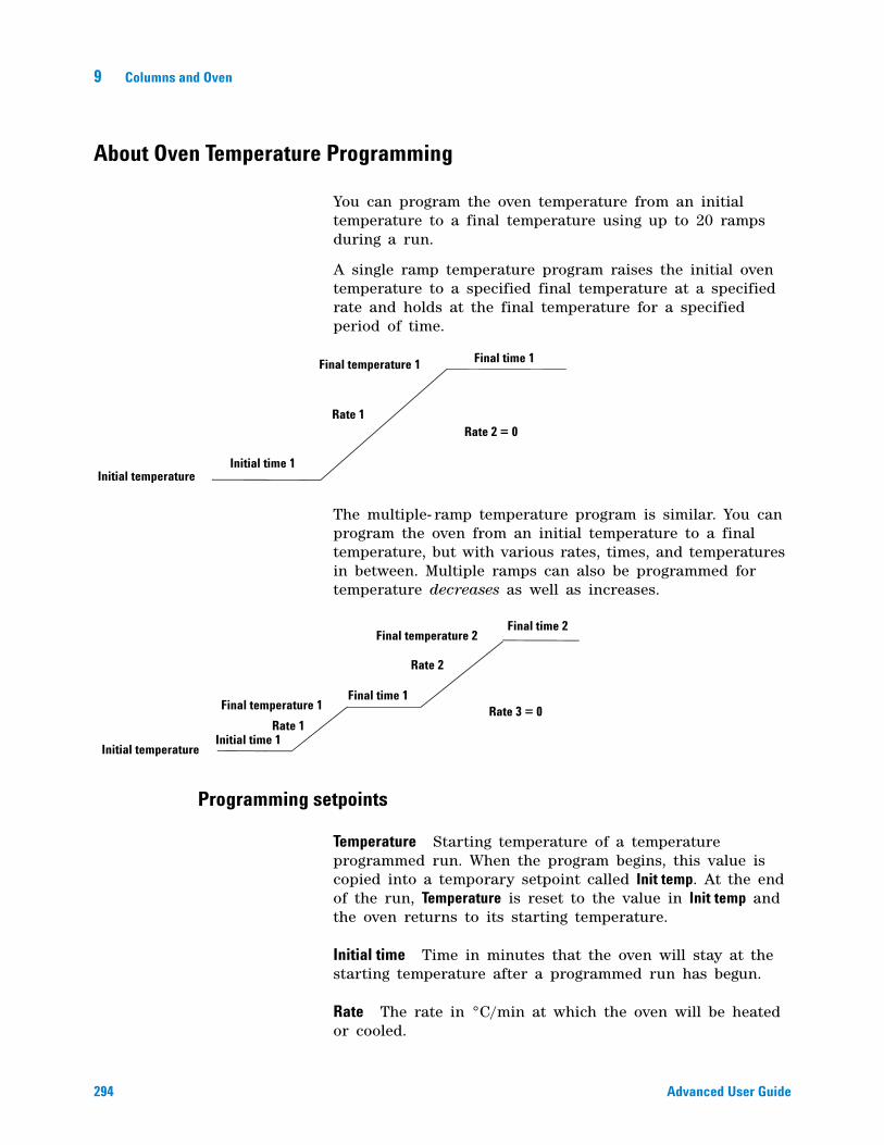
294 Advanced User Guide
9 Columns and Oven
About Oven Temperature Programming
You can program the oven temperature from an initial temperature to a final temperature using up to 20 ramps during a run.
A single ramp temperature program raises the initial oven temperature to a specified final temperature at a specified rate and holds at the final temperature for a specified period of time.
The multiple- ramp temperature program is similar. You can program the oven from an initial temperature to a final temperature, but with various rates, times, and temperatures in between. Multiple ramps can also be programmed for temperature decreases as well as increases.
Programming setpoints
Temperature Starting temperature of a temperature programmed run. When the program begins, this value is copied into a temporary setpoint called Init temp. At the end of the run, Temperature is reset to the value in Init temp and the oven returns to its starting temperature.
Initial time Time in minutes that the oven will stay at the starting temperature after a programmed run has begun.
Rate The rate in °C/min at which the oven will be heated or cooled.
Initial temperatureInitial time 1
Rate 1
Final temperature 1 Final time 1
Rate 2 = 0
Initial temperatureInitial time 1
Rate 1
Final temperature 1Final time 1
Rate 2
Final temperature 2Final time 2
Rate 3 = 0
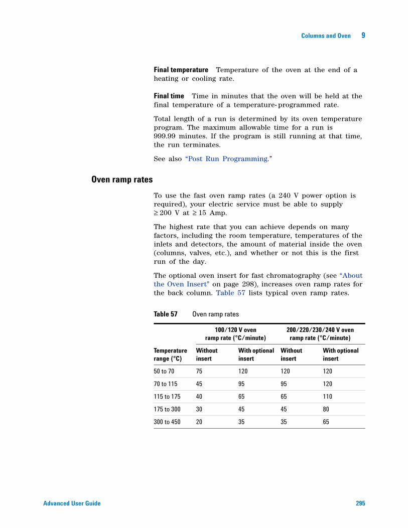
Columns and Oven 9
Advanced User Guide 295
Final temperature Temperature of the oven at the end of a heating or cooling rate.
Final time Time in minutes that the oven will be held at the final temperature of a temperature- programmed rate.
Total length of a run is determined by its oven temperature program. The maximum allowable time for a run is 999.99 minutes. If the program is still running at that time, the run terminates.
See also “Post Run Programming.”
Oven ramp rates
To use the fast oven ramp rates (a 240 V power option is required), your electric service must be able to supply ≥ 200 V at ≥ 15 Amp.
The highest rate that you can achieve depends on many factors, including the room temperature, temperatures of the inlets and detectors, the amount of material inside the oven (columns, valves, etc.), and whether or not this is the first run of the day.
The optional oven insert for fast chromatography (see “About the Oven Insert” on page 298), increases oven ramp rates for the back column. Table 57 lists typical oven ramp rates.
Table 57 Oven ramp rates
100/120 V oven ramp rate (°C/minute)
200/220/230/240 V oven ramp rate (°C/minute)
Temperature range (°C)
Without insert
With optional insert
Without insert
With optional insert
50 to 70 75 120 120 120
70 to 115 45 95 95 120
115 to 175 40 65 65 110
175 to 300 30 45 45 80
300 to 450 20 35 35 65
296 Advanced User Guide
9 Columns and Oven
Setting the oven parameters for constant temperature
An isothermal run is one in which the oven is maintained at a constant temperature. For an isothermal run, set Rate 1 to zero.
1 Press [Oven] to open the oven parameter list.
2 Enter the oven temperature for the isothermal run.
3 Enter the number of minutes (Initial time) that you want the oven to stay at this temperature. This time is the duration of the run.
4 If Rate 1 is not already 0, enter zero for an isothermal run.
Setting the oven parameters for ramped temperature
Single ramp
1 Press [Oven] to open the oven parameter list.
2 Enter a starting temperature (Temperature).
3 Enter the time (Initial time) that you want the oven to stay at Temperature.
4 Enter the rate (Rate 1) at which the oven temperature is to change.
5 Enter the final temperature (Final temperature 1).
6 Enter the time (Final time 1) the oven is to hold Final temperature 1.
7 To end the oven ramp program after Ramp 1, set Rate 2 to zero.
Multiple ramps
In a multiple- ramp program, Final time for one ramp is also Initial time for the next ramp. Thus, there is only one Initial time.
1 Set up the first oven ramp as described in “Single ramp”.
2 Enter the rate (Rate 2) at which you want the oven temperature to increase for the second oven ramp.
3 Enter the final temperature (Final temperature 2).
4 Enter the number of minutes (Final time 2) that you want the oven to hold the final temperature.
5 To end the temperature program after the second ramp, set Rate 3 to zero.

Columns and Oven 9
Advanced User Guide 297
6 To add additional oven ramps, repeat the steps described.
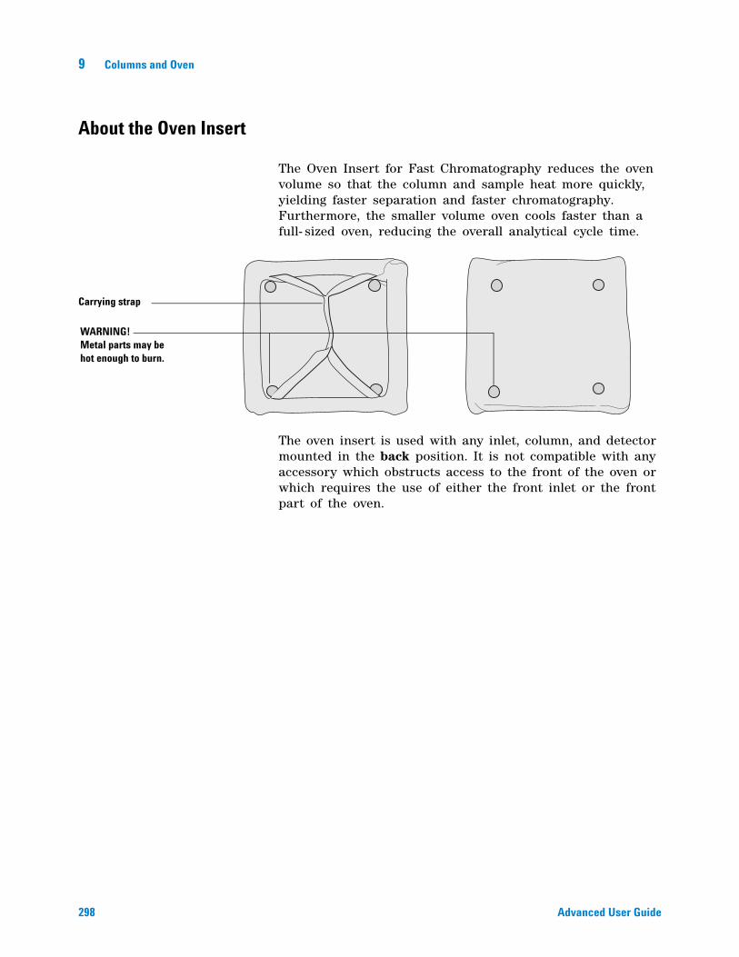
298 Advanced User Guide
9 Columns and Oven
About the Oven Insert
The Oven Insert for Fast Chromatography reduces the oven volume so that the column and sample heat more quickly, yielding faster separation and faster chromatography. Furthermore, the smaller volume oven cools faster than a full- sized oven, reducing the overall analytical cycle time.
The oven insert is used with any inlet, column, and detector mounted in the back position. It is not compatible with any accessory which obstructs access to the front of the oven or which requires the use of either the front inlet or the front part of the oven.
Carrying strap
WARNING! Metal parts may be hot enough to burn.
Columns and Oven 9
Advanced User Guide 299
About Columns
In all GCs, a sample—which is a mixture of several components—is vaporized in an inlet, separated in a column, and examined in a detector.
The column separates components in time because:
• When a vaporized component is presented with a gas phase and a coating phase, it divides between the two phases according to its relative attraction to the two phases.
• The “attraction” can be solubility, volatility, polarity, specific chemical interaction, or any other property that differs from one component to another.
• If one phase is stationary (the coating) and the other is moving (the carrier gas), the component will travel at a speed less than that of the moving phase. How much less depends on the strength of the attraction.
• If different components have different “attractions”, they will separate in time.
Selecting the correct packed glass column type
This topic is covered in the Maintenance manual. See To attach a packed column to the purged packed inlet for details.
About the column modes
The flow modes available are determined by the GC inlet’s control mode. When the inlet’s control mode is set to Pressure control, all of the flow modes and pressure modes below are available for the column. When the inlets control mode is set to Flow control, the column’s mode is not selectable. For an inlet’s mode of Flow control, only column flow can be entered.
The flow modes
Flow rates are corrected to NTP (normal temperature and pressure, 25 °C and 1 atmosphere.
300 Advanced User Guide
9 Columns and Oven
• Constant flow—Maintains a constant mass flow rate of carrier gas in the column throughout the run. If the column resistance changes due to a temperature program, the column head pressure is adjusted to keep the flow rate constant. This can shorten runs significantly.
• Ramped flow—Increases the mass flow rate in the column during the run according to a program you enter. A column flow profile can have up to three ramps, each consisting of a programmed increase followed by a hold period.
The pressure modes
The pressure modes are not available if the column is not defined or the inlet’s mode is set to Flow control.
Pressures are gauge pressures—the difference between the absolute pressure and the local atmospheric pressure. Because most detectors present little resistance to the column flow, the gauge pressure at the column head is usually the same as the pressure difference between column inlet and exit. The mass selective detector and the atomic emission detector are the exceptions.
• Constant pressure—Maintains a constant gauge pressure at the head of the column throughout the run. If the column resistance and gas density changes during a run, the gauge pressure does not change but the mass flow rate does.
• Ramped pressure—Increases the column head gauge pressure during the run according to a program you enter. A column pressure profile can have up to three ramps, each consisting of a programmed increase followed by a hold period.
Select a column mode
The column’s mode parameter is not available if the inlet’s mode parameter is set to Flow control.
When a splitter controlled by a PCM or AUX pressure is used to divide flow between multiple columns, only the mode setting of the lowest column number configured determines the mode used. All other column mode settings exiting the splitter are ignored by the GC.
1 Press [Col 1] or [Col 2], or press [Aux col #] and enter the column number.
2 Scroll to the Mode line.
Columns and Oven 9
Advanced User Guide 301
3 Press [Mode/Type] to see the column mode list.
4 Scroll to the column mode you want. Press [Enter].
This completes column mode selection. Next you must specify the inlet conditions either during the entire run (if you selected either of the constant modes) or at the beginning of the run (if you selected either of the ramped modes).
Setting the column parameters for constant flow or constant pressure
If the column is defined, you can enter any one of these quantities—the GC will calculate and display the other two.
For example, you may have selected Constant pressure as the column mode. You decide to specify, as a starting condition, the column flow. The GC will compute the pressure necessary to achieve this flow (as well as the average linear velocity) and hold this pressure constant during the run.
If you select Constant flow as the mode and specify column flow as the initial condition, the GC will still calculate the pressure necessary to achieve this flow, but it will adjust the pressure as necessary to maintain constant flow.
If the column is not defined, you can enter only pressure. Constant flow can still be specified, but the GC cannot know what the flow is.
1 Press [Col 1] or [Col 2], or press [Aux col #] and enter the column number.
2 Scroll to the Pressure or Flow or Velocity line.
3 Type the desired initial value, followed by [Enter]. The GC will compute and display the other two values. Adjust them, if you choose to, by repeating steps 2 and 3 but note that changing any one changes all three.
This completes setting the initial carrier gas condition.
Enter a flow or pressure program (optional)
If you selected either the ramped pressure or ramped flow column mode, the column parameter list contains entries for setting up a ramp program.
You begin with an initial value, either Initial Pressure or Initial Flow, and an Initial time. At the end of that time, Rate 1 begins and runs until it reaches Final pressure (or Final flow). It
302 Advanced User Guide
9 Columns and Oven
remains at that value for Final time 1. You can then add a second and third ramp, each consisting of a Rate, a Final value (pressure or flow), and a Final time.
The program ends when it reaches a Rate that is set to 0 (Off).
When a flow or pressure program is running, the Pressure, Flow, and Velocity lines that you used to set constant conditions show the progress of the program.
The oven program determines the length of the run. If a flow or pressure program ends before the analytical run does, the flow (or pressure) remains at the last final value.
Programming column pressure or flow
1 Press [Col 1] or [Col 2], or press [Aux col #] and enter the column number.
2 Scroll to Initial pressure (or Initial flow). Type the desired value and press [Enter].
3 Similarly, enter a value for Initial time. This completes the initial part of the program.
4 To begin a ramp, enter a positive value for Rate 1. It does not matter whether you are programming up or down—the rate is always positive.
5 If Rate 1 is zero, the program ends here. If you enter any other value, the Final value lines for the first ramp appear and the cursor moves to the line.
6 Enter values for Final pressure 1 (or Final flow 1) and Final time 1. This completes the first ramp.
7 To enter a second ramp, scroll to the appropriate Rate line and repeat steps 5 and 6. A maximum of 20 ramps can be entered.
Columns and Oven 9
Advanced User Guide 303
Backflushing a Column
Backflush is a means of discarding high- boilers from a column after the peaks of interest have eluted. It saves analysis time and has these additional benefits:
• Longer column life
• less high temperature exposure
• removal of high- boilers
• protection from air and water at high temperatures
• Less chemical background
• ghost peaks
• “wrap- around” of late eluters from previous runs
• stationary phase decomposition peaks
• Less contamination of the mass selective detector (MSD) source, if using MSD
• longer time between source cleanings
• higher stability of calibrations
Agilent now provides two Backflush Wizard software utilities. One is available with the Instrument Utilities software, and the other is an add- on for your Agilent data systems. These utilities complement each other, and automate the process of updating the GC and method to implement and validate successful backflushing. Contact your Agilent sales representative for more information
If not using an Agilent Backflush Wizard, you will need to experimentally determine the correct flow/pressure settings and the backflush time appropriate for your analysis. Determine the correct values by testing the backflush method, then running a blank to check for residual late eluters.
Refer to the Agilent web site at http://www.agilent.com/chem for example backflush applications, especially if using an MSD.
CAUTION Only backflush an inlet that has a split vent line with a chemical trap, such as the split/splitless, PTV, and VI. Attempts to backflush using other inlet types will most likely damage the pneumatics flow modules.
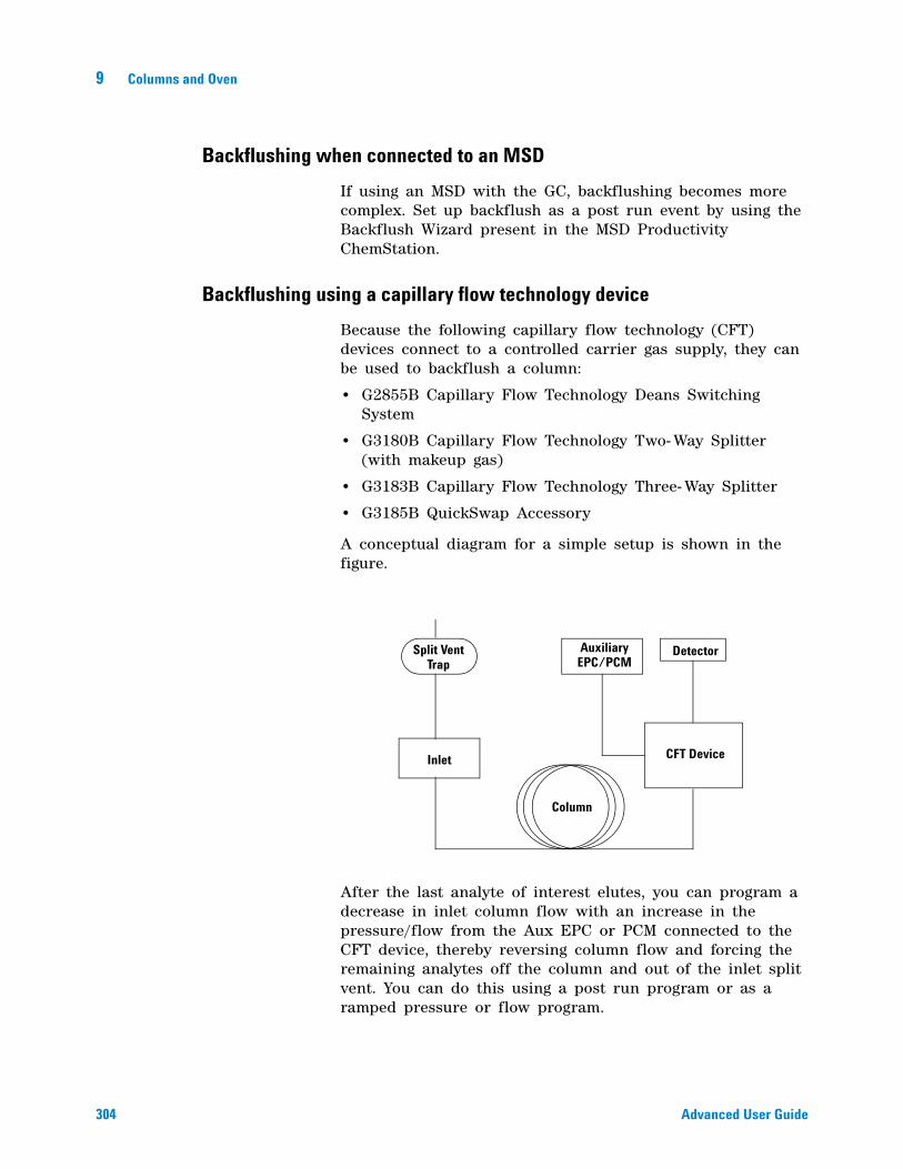
304 Advanced User Guide
9 Columns and Oven
Backflushing when connected to an MSD
If using an MSD with the GC, backflushing becomes more complex. Set up backflush as a post run event by using the Backflush Wizard present in the MSD Productivity ChemStation.
Backflushing using a capillary flow technology device
Because the following capillary flow technology (CFT) devices connect to a controlled carrier gas supply, they can be used to backflush a column:
• G2855B Capillary Flow Technology Deans Switching System
• G3180B Capillary Flow Technology Two- Way Splitter (with makeup gas)
• G3183B Capillary Flow Technology Three- Way Splitter
• G3185B QuickSwap Accessory
A conceptual diagram for a simple setup is shown in the figure.
After the last analyte of interest elutes, you can program a decrease in inlet column flow with an increase in the pressure/flow from the Aux EPC or PCM connected to the CFT device, thereby reversing column flow and forcing the remaining analytes off the column and out of the inlet split vent. You can do this using a post run program or as a ramped pressure or flow program.
Split VentTrap
Inlet
Column
CFT Device
AuxiliaryEPC/PCM
Detector
Columns and Oven 9
Advanced User Guide 305
To set up a post run backflush
A main advantage of the post- run backflush method is that the GC turns off detection during this time. If using an MSD, this helps prevent damage to the detector and is the recommended backflush method.
If using an Agilent data system, a Backflush Wizard provides a straightforward interface for making these settings.
1 Verify that all columns are properly configured.
2 Since the backflush will run as a post- run program, set the method so that the oven program ends after the last peak of interest returns to baseline, or after reaching the last temperature of interest.
3 Press [Post Run] and enter the backflush duration as the Time.
• The oven temperature and column pressure/flow setpoints for installed columns appear.
• Whether you can enter a pressure or flow for a column depends on its mode (pressure or flow).
• Some inlets, such as the multimode inlet, also provide a post run inlet temperature and total flow rate.
4 Enter the oven temperature for the backflush.
5 Enter the backflush flow(s) or pressure(s).
If in flow mode:
• Enter a negative flow for the column connected between the inlet and the CFT device. The GC will automatically establish the corresponding pressures needed in the inlet and the CFT device.
• Increase the flow rates in the column(s) connected between the CFT device and the detector(s).
If in pressure mode:
• Set the pressure of the column connected between the inlet and the CFT device to 0.000. This turns off flow from the inlet.
• Increase the pressure of the primary column connected between the CFT device and the detector(s). This creates the backward flow through the column and increases the flow through any connected detectors.
6 If using a multimode inlet, enter a total flow and inlet temperature for the post run (backflush) period.
306 Advanced User Guide
9 Columns and Oven
When developing the backflush portion of your method, consider the following:
• Ensure that the split vent flow setpoint is at least 25 mL/min and at least 50% more than the column backflush flow rate.
• If using gas saver, ensure that the gas saver flow setpoint is at least 25 mL/min and at least 50% more than the column backflush flow rate.
To backflush using a ramped pressure program
In this case, the backflush occurs as part of the run, so the detectors continue to collect data. During the backflush, you may wish to turn off data collection in the data system.
1 Verify that all columns are properly configured.
2 Enter all method parameters for the analysis: sampler parameters, inlet parameters, oven temperature profile, detector flows and temperatures, and so forth.
3 Program the oven for the backflush.
• Include any temperature profile needed for backflush.
• Set the total run time to include sufficient time for backflush.
4 Program the pressure ramp for the column installed between the inlet and the CFT device. After the last analyte elutes or after reaching the last temperature of interest, program a fast ramp (for example, 30 psi/min) with a final pressure of 0.
5 Program the pressure ramp for the primary column installed between the CFT device and the detector. The pressure should increase slightly during the backflush duration so that the flow into the detectors remains relatively stable.
If you turned off data acquisition in a data system during backflush, remember to turn it on again at the end of the run.
CAUTION To avoid damage to an MSD, Agilent strongly recommends setting up backflush as a post run event, not as part of a ramped column program. If you still choose to backflush as part of a run, be very careful that the flow into the MSD does not exceed the limits of the vacuum pump.
Columns and Oven 9
Advanced User Guide 307
To backflush using a ramped flow program
In this case, the backflush occurs as part of the run, so the detectors continue to collect data. During the backflush, you may wish to turn off data collection in the data system.
1 Verify that all columns are properly configured.
2 Enter all method parameters for the analysis: sampler parameters, inlet parameters, oven temperature profile, detector flows and temperatures, and so forth.
3 Program the oven for the backflush.
• Include any temperature profile needed for backflush.
• Set the total run time to include sufficient time for backflush.
4 Program the flow ramp for the column installed between the inlet and the CFT device. After the last analyte elutes or after reaching the last temperature of interest, program a fast ramp with a final flow that is negative.
5 Program the flow ramp for the primary column installed between the CFT device and the detector. Typically hold at the method’s final value for the backflush duration.
If you turned off data acquisition in a data system during backflush, remember to turn it on again at the end of the run.
Backflushing using a switching valve
Backflushing is done using a column switching valve controlled by the Run Table. See “Run Time Programming” on page 16.
The valve is plumbed as follows:
• Position 1 Carrier gas flows through the column to the detector. This is the normal flow path.
• Position 2 Carrier gas flows through the column toward the inlet, removing components on the column through the inlet vent line.
CAUTION To avoid damage to an MSD, Agilent strongly recommends setting up backflush as a post run event, not as part of a ramped column program. If you still choose to backflush as part of a run, be very careful that the flow into the MSD does not exceed the limits of the vacuum pump.
308 Advanced User Guide
9 Columns and Oven
The Run Table contains commands to perform these actions:
• After the last peak of interest appears, switch the valve to Position 2. Higher boiling peaks are discarded through the inlet vent.
• At the same time, turn data acquisition off.
• At the end of the backflush period (determined experimentally), switch the valve to Position 1 and turn data acquisition on. The system is now ready for the next run.
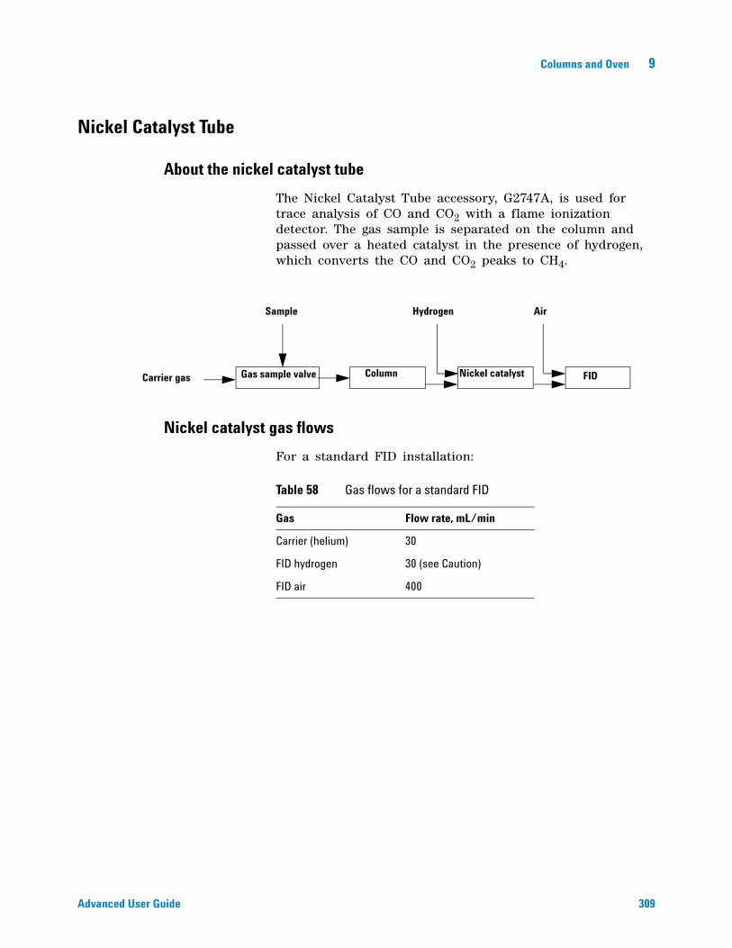
Columns and Oven 9
Advanced User Guide 309
Nickel Catalyst Tube
About the nickel catalyst tube
The Nickel Catalyst Tube accessory, G2747A, is used for trace analysis of CO and CO2 with a flame ionization detector. The gas sample is separated on the column and passed over a heated catalyst in the presence of hydrogen, which converts the CO and CO2 peaks to CH4.
Nickel catalyst gas flows
For a standard FID installation:
Carrier gas
Sample Hydrogen Air
Gas sample valve Column Nickel catalyst FID
Table 58 Gas flows for a standard FID
Gas Flow rate, mL/min
Carrier (helium) 30
FID hydrogen 30 (see Caution)
FID air 400
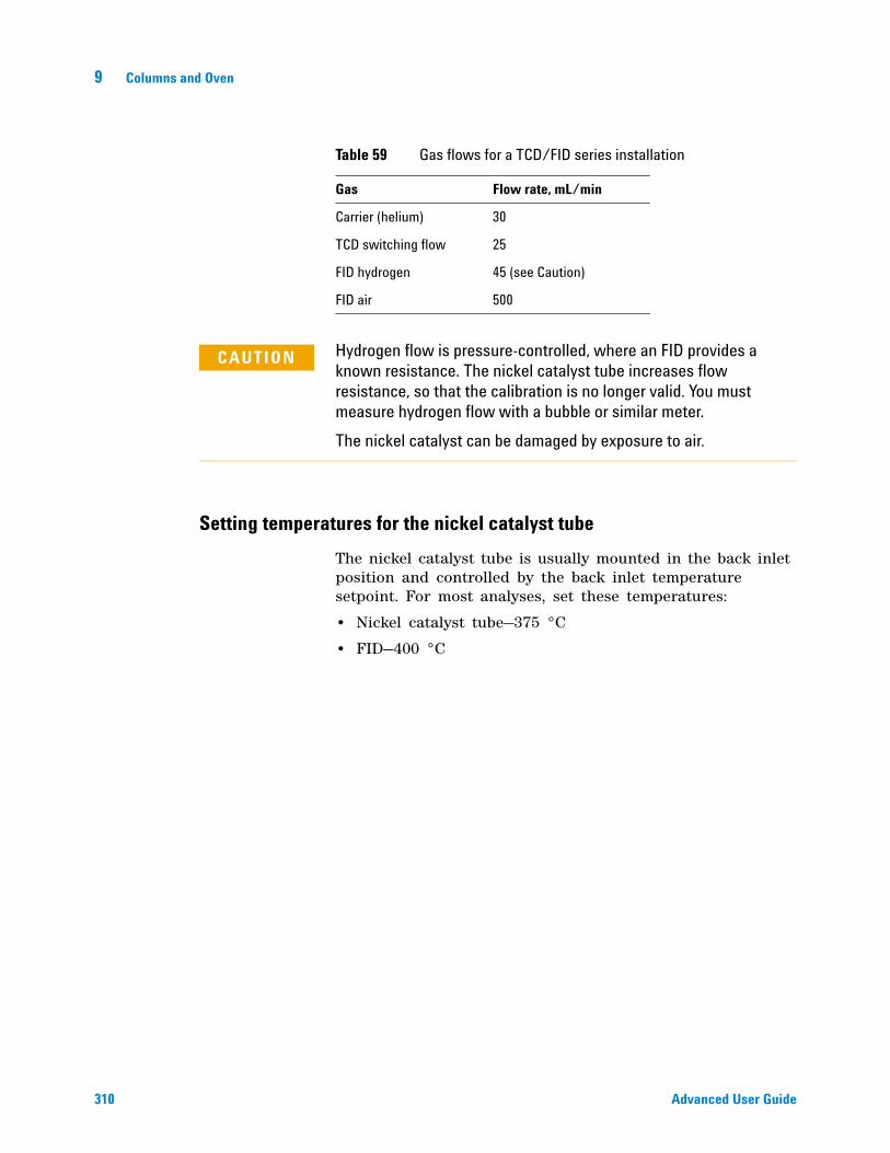
310 Advanced User Guide
9 Columns and Oven
Setting temperatures for the nickel catalyst tube
The nickel catalyst tube is usually mounted in the back inlet position and controlled by the back inlet temperature setpoint. For most analyses, set these temperatures:
• Nickel catalyst tube—375 °C
• FID—400 °C
Table 59 Gas flows for a TCD/FID series installation
Gas Flow rate, mL/min
Carrier (helium) 30
TCD switching flow 25
FID hydrogen 45 (see Caution)
FID air 500
CAUTION Hydrogen flow is pressure-controlled, where an FID provides a known resistance. The nickel catalyst tube increases flow resistance, so that the calibration is no longer valid. You must measure hydrogen flow with a bubble or similar meter.
The nickel catalyst can be damaged by exposure to air.
311
Agilent 7890A Gas ChromatographAdvanced User Guide
Agilent Technologies
10Detectors
About Makeup Gas 312
About the FID 313
About the TCD 318
About the uECD 326
About the NPD 332
About the FPD 344
312 Advanced User Guide
10 Detectors
About Makeup Gas
Most detectors use a makeup gas to increase the flow rate through the detector body. This sweeps peaks out of the detector quickly, avoiding mixing of components and loss of resolution. This is particularly important with capillary columns because the column flow rates are so small.
The makeup gas line of your detector parameter list changes depending on your instrument configuration.
If you have an inlet with the column not defined, the makeup flow is constant. If you are operating with column defined, you have a choice of two makeup gas modes.
Constant makeup This mode provides a constant flow of makeup gas to the detector.
Column + makeup = constant This mode provides a variable flow of makeup gas to the detector. As column flow increases or decreases, the makeup flow changes to provide a constant combined flow to the detector. If you choose this option, enter a value under Combined flow. The Combined flow line always displays the same value, while the Makeup line changes as the actual makeup flow changes.
To change the makeup gas flow mode
1 Press [Front Det] or [Back Det].
2 Scroll to Mode. Press [Mode/Type].
3 Scroll to the correct mode and press [Enter].
Detectors 10
Advanced User Guide 313
About the FID
The FID passes sample and carrier gas from the column through a hydrogen- air flame. The hydrogen- air flame alone creates few ions, but burning an organic compound increases the number of ions produced. A polarizing voltage attracts these ions to a collector located near the flame. The current produced is proportional to the amount of sample being burned. This current is sensed by an electrometer, converted to digital form, and sent to an output device.
The FID uses three supply gases (hydrogen, makeup gas, and air) and two supply lines. Air flows through one supply line, while hydrogen mixed with the makeup gas flows through the other. All three supply gases use:
• A filter frit to protect the flow path and limit the flow rate
• A proportional valve to control the pressure
• A pressure sensor and restrictor to control the valve
The hydrogen and makeup mix outside the flow module and enter the detector at the base of the jet. Air enters above the jet.
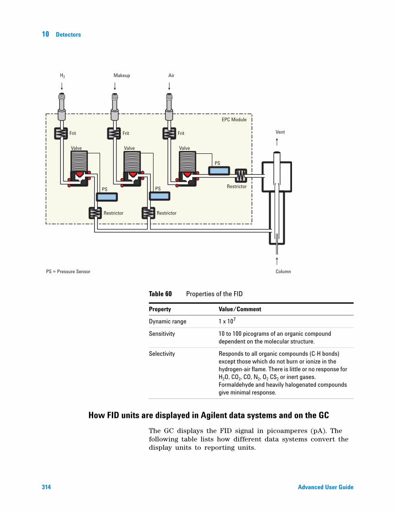
314 Advanced User Guide
10 Detectors
How FID units are displayed in Agilent data systems and on the GC
The GC displays the FID signal in picoamperes (pA). The following table lists how different data systems convert the display units to reporting units.
Valve
Frit Frit
Valve
PS = Pressure Sensor Column
PS
PSPS
Valve
Frit
Restrictor Restrictor
Restrictor
EPC Module
H2 Air
Vent
Makeup
Table 60 Properties of the FID
Property Value/Comment
Dynamic range 1 x 10⁷
Sensitivity 10 to 100 picograms of an organic compound dependent on the molecular structure.
Selectivity Responds to all organic compounds (C-H bonds) except those which do not burn or ionize in the hydrogen-air flame. There is little or no response for H2O, CO2, CO, N2, O2 CS2 or inert gases. Formaldehyde and heavily halogenated compounds give minimal response.
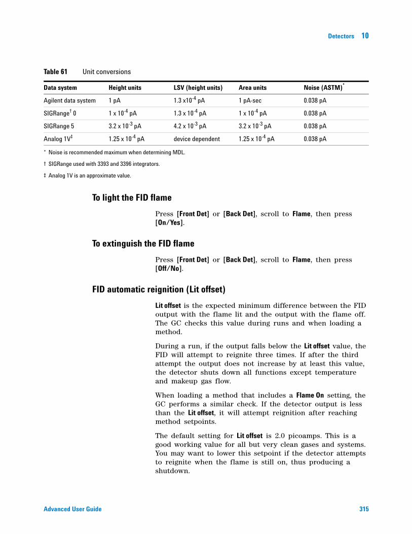
Detectors 10
Advanced User Guide 315
To light the FID flame
Press [Front Det] or [Back Det], scroll to Flame, then press [On/Yes].
To extinguish the FID flame
Press [Front Det] or [Back Det], scroll to Flame, then press [Off/No].
FID automatic reignition (Lit offset)
Lit offset is the expected minimum difference between the FID output with the flame lit and the output with the flame off. The GC checks this value during runs and when loading a method.
During a run, if the output falls below the Lit offset value, the FID will attempt to reignite three times. If after the third attempt the output does not increase by at least this value, the detector shuts down all functions except temperature and makeup gas flow.
When loading a method that includes a Flame On setting, the GC performs a similar check. If the detector output is less than the Lit offset, it will attempt reignition after reaching method setpoints.
The default setting for Lit offset is 2.0 picoamps. This is a good working value for all but very clean gases and systems. You may want to lower this setpoint if the detector attempts to reignite when the flame is still on, thus producing a shutdown.
Table 61 Unit conversions
Data system Height units LSV (height units) Area units Noise (ASTM)*
Agilent data system 1 pA 1.3 x10⁻⁴ pA 1 pA-sec 0.038 pA
SIGRange† 0 1 x 10⁻⁴ pA 1.3 x 10⁻⁴ pA 1 x 10⁻⁴ pA 0.038 pA
SIGRange 5 3.2 x 10⁻³ pA 4.2 x 10⁻³ pA 3.2 x 10⁻³ pA 0.038 pA
Analog 1V‡ 1.25 x 10⁻⁴ pA device dependent 1.25 x 10⁻⁴ pA 0.038 pA
* Noise is recommended maximum when determining MDL.
† SIGRange used with 3393 and 3396 integrators.
‡ Analog 1V is an approximate value.
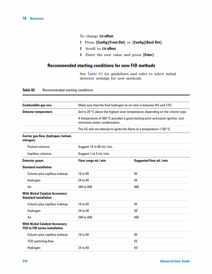
316 Advanced User Guide
10 Detectors
To change Lit offset:
1 Press [Config][Front Det] or [Config][Back Det].
2 Scroll to Lit offset.
3 Enter the new value and press [Enter].
Recommended starting conditions for new FID methods
See Table 62 for guidelines and rules to select initial detector settings for new methods.
Table 62 Recommended starting conditions
Combustible gas mix Make sure that the final hydrogen-to-air ratio is between 8% and 12%
Detector temperature Set to 20 °C above the highest oven temperature, depending on the column type.
A temperature of 300 °C provides a good starting point and easier ignition, and minimizes water condensation.
The GC will not attempt to ignite the flame at a temperature <150 °C.
Carrier gas flow (hydrogen, helium, nitrogen)
Packed columns Suggest 10 to 60 mL/min
Capillary columns Suggest 1 to 5 mL/min
Detector gases Flow range mL/min Suggested flow mL/min
Standard installation
Column plus capillary makeup 10 to 60 30
Hydrogen 24 to 60 30
Air 200 to 600 400
With Nickel Catalyst Accessory: Standard installation
Column plus capillary makeup 10 to 60 30
Hydrogen 24 to 60 30*
Air 200 to 600 400
With Nickel Catalyst Accessory: TCD to FID series installation
Column plus capillary makeup 10 to 60 30
TCD switching flow 25
Hydrogen 24 to 60 45*
Detectors 10
Advanced User Guide 317
Use nitrogen makeup gas (instead of helium) for greater sensitivity.
Setting parameters for FID
To set the FID parameters:
1 Verify:
• Makeup gas is configured
• Installed jet type is correct for column type
2 Press [Front Det] or [Back Det].
3 Set the detector temperature. The temperature must be greater than 150 °C for the flame to light.
4 Set the hydrogen flow rate, if desired, and press [Off/No].
5 Change the air flow rate, if desired, and press [Off/No].
6 If using a packed column, set the FID makeup gas to 0.0/Off.
7 If using a defined capillary column, set the makeup gas flow or combined column plus makeup gas flow.
8 Scroll to Flame and press [On/Yes]. This turns on the air and hydrogen and initiates the ignition sequence. The signal typically increases to 5 to 20 pA after ignition.
Verify that the flame is lit by holding a cold, shiny surface, such as a mirror or chrome- plated wrench, over the collector exit. Steady condensation indicates that the flame is lit.
Air 200 to 600 450
* Detector hydrogen is pressure controlled, where the detector provides a known resistance. If using a nickel catalyst tube, the resistance changes, and the flow rates displayed by the GC will not be accurate. Measure the actual hydrogen flow using a flow meter at the detector vent, with all other flows turned off.
Table 62 Recommended starting conditions (continued)
WARNING Verify that a column is installed or the FID column fitting is plugged before turning on the air or hydrogen. An explosion may occur if air and hydrogen are allowed to leak into the oven.
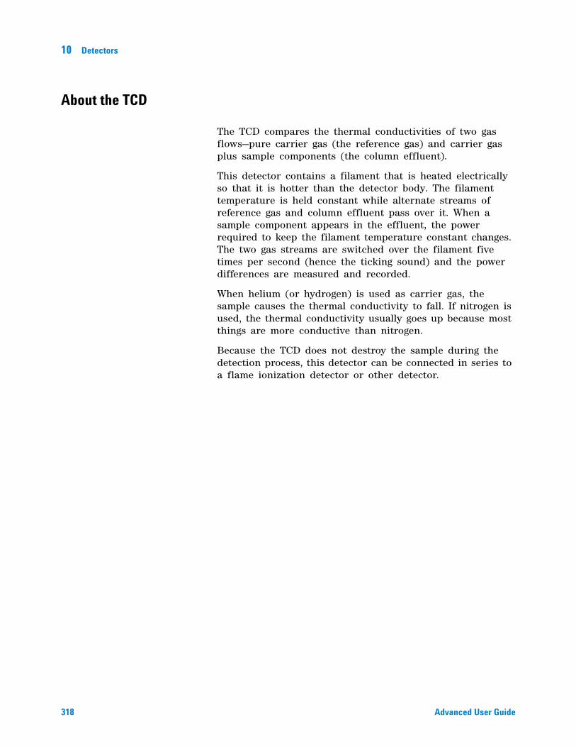
318 Advanced User Guide
10 Detectors
About the TCD
The TCD compares the thermal conductivities of two gas flows—pure carrier gas (the reference gas) and carrier gas plus sample components (the column effluent).
This detector contains a filament that is heated electrically so that it is hotter than the detector body. The filament temperature is held constant while alternate streams of reference gas and column effluent pass over it. When a sample component appears in the effluent, the power required to keep the filament temperature constant changes. The two gas streams are switched over the filament five times per second (hence the ticking sound) and the power differences are measured and recorded.
When helium (or hydrogen) is used as carrier gas, the sample causes the thermal conductivity to fall. If nitrogen is used, the thermal conductivity usually goes up because most things are more conductive than nitrogen.
Because the TCD does not destroy the sample during the detection process, this detector can be connected in series to a flame ionization detector or other detector.
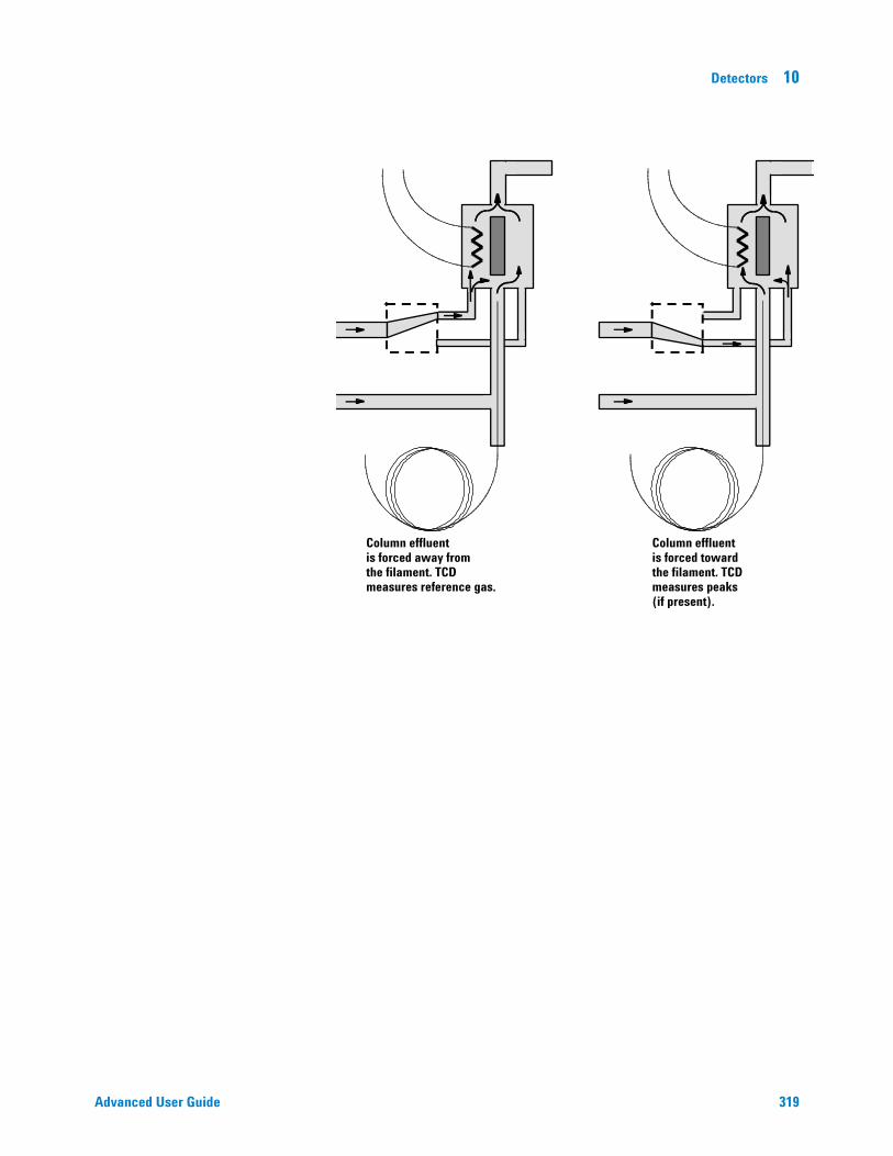
Detectors 10
Advanced User Guide 319
Column effluentis forced away fromthe filament. TCDmeasures reference gas.
Column effluentis forced towardthe filament. TCDmeasures peaks(if present).
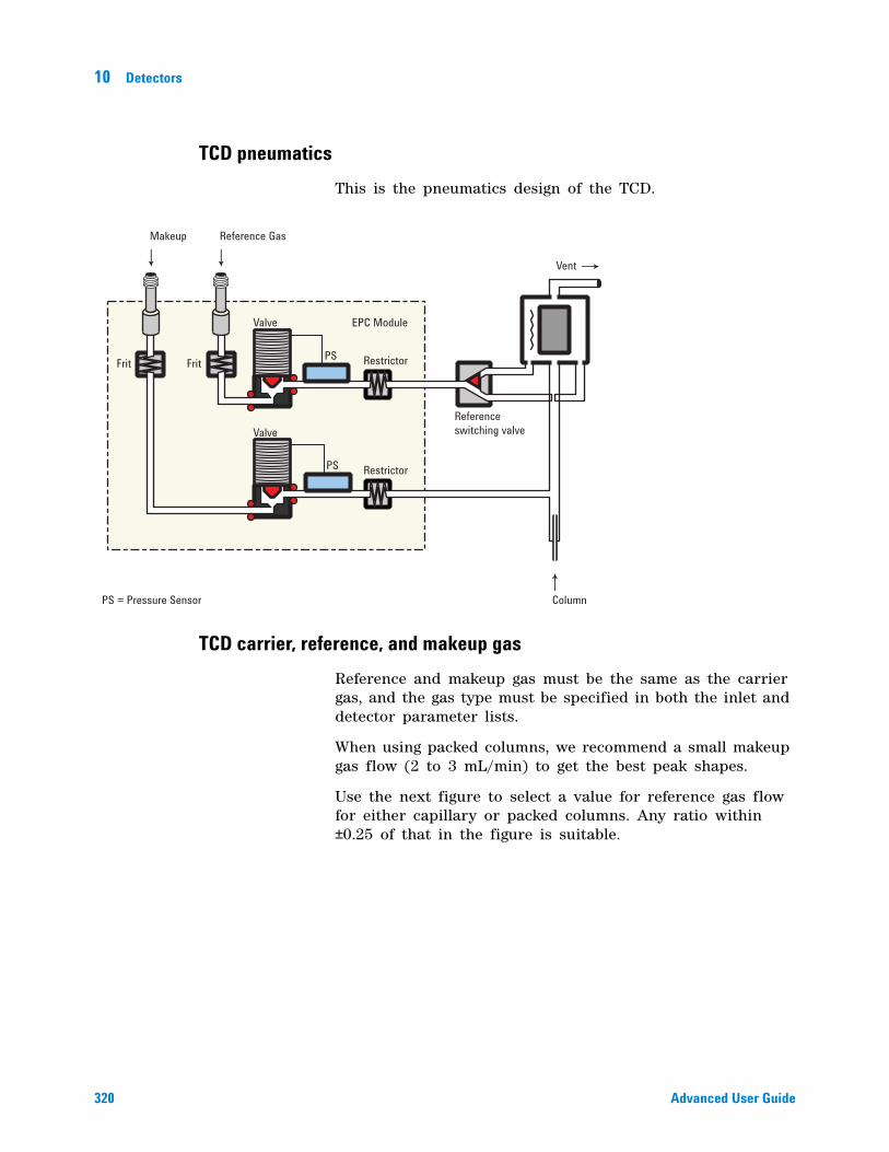
320 Advanced User Guide
10 Detectors
TCD pneumatics
This is the pneumatics design of the TCD.
TCD carrier, reference, and makeup gas
Reference and makeup gas must be the same as the carrier gas, and the gas type must be specified in both the inlet and detector parameter lists.
When using packed columns, we recommend a small makeup gas flow (2 to 3 mL/min) to get the best peak shapes.
Use the next figure to select a value for reference gas flow for either capillary or packed columns. Any ratio within ±0.25 of that in the figure is suitable.
PS = Pressure Sensor
Vent
PS
Valve
FritFrit
Referenceswitching valve
Restrictor
EPC Module
Reference GasMakeup
PS
Restrictor
Valve
Column
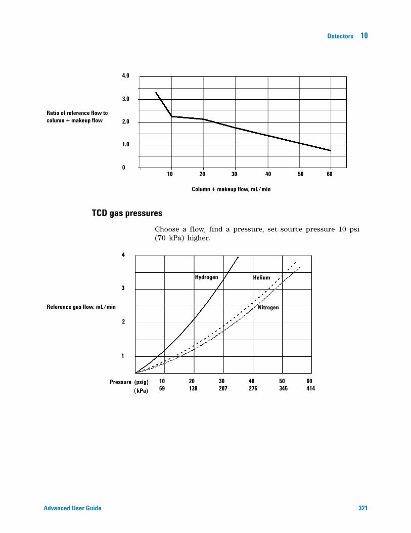
Detectors 10
Advanced User Guide 321
TCD gas pressures
Choose a flow, find a pressure, set source pressure 10 psi (70 kPa) higher.
Ratio of reference flow to column + makeup flow
4.0
3.0
2.0
1.0
0
Column + makeup flow, mL/min
605040302010
Hydrogen Helium
NitrogenReference gas flow, mL/min
Pressure (psig) (kPa)
4
3
2
1
10 69
60 414
50 345
40 276
30 207
20 138
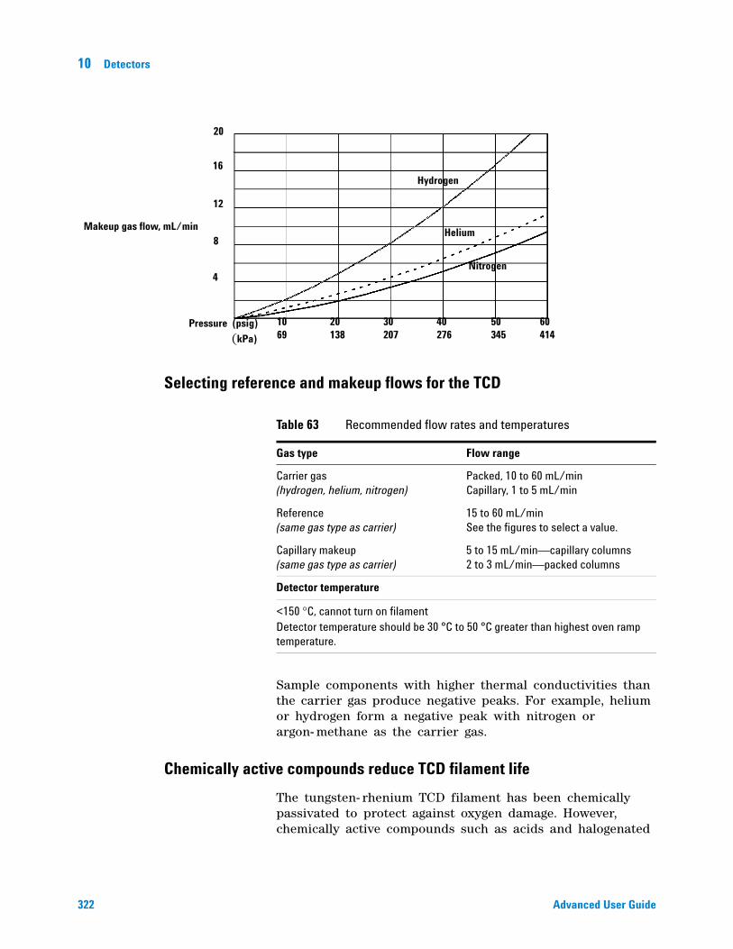
322 Advanced User Guide
10 Detectors
Selecting reference and makeup flows for the TCD
Sample components with higher thermal conductivities than the carrier gas produce negative peaks. For example, helium or hydrogen form a negative peak with nitrogen or argon- methane as the carrier gas.
Chemically active compounds reduce TCD filament life
The tungsten- rhenium TCD filament has been chemically passivated to protect against oxygen damage. However, chemically active compounds such as acids and halogenated
Makeup gas flow, mL/min
Hydrogen
Helium
Nitrogen
Pressure (psig) (kPa)
10 69
60 414
50 345
40 276
30 207
20 138
4
8
12
16
20
Table 63 Recommended flow rates and temperatures
Gas type Flow range
Carrier gas (hydrogen, helium, nitrogen)
Packed, 10 to 60 mL/min Capillary, 1 to 5 mL/min
Reference (same gas type as carrier)
15 to 60 mL/min See the figures to select a value.
Capillary makeup (same gas type as carrier)
5 to 15 mL/min—capillary columns 2 to 3 mL/min—packed columns
Detector temperature
<150 °C, cannot turn on filamentDetector temperature should be 30 °C to 50 °C greater than highest oven ramp temperature.
Detectors 10
Advanced User Guide 323
compounds may attack the filament. The immediate symptom is a permanent change in detector sensitivity due to a change in filament resistance.
If possible, such compounds should be avoided. If this is not possible, the filament may have to be replaced frequently.
Changing the TCD polarity during a run
Negative polarity On inverts the peak so the integrator or ChemStation can measure it. Negative polarity can be a run table entry; see “Run Time Programming” on page 16.
Detecting hydrogen with the TCD using helium carrier gas
Hydrogen is the only element with thermal conductivity greater than helium, and mixtures of small amounts of hydrogen (<20%) in helium at moderate temperatures exhibit thermal conductivities less than either component alone. If you are analyzing for hydrogen with helium carrier gas, a hydrogen peak may appear as positive, negative, or as a split peak.
There are two solutions to this problem:
• Use nitrogen or argon- methane as carrier gas. This eliminates problems inherent with using helium as carrier, but causes reduced sensitivity to components other than hydrogen.
• Operate the detector at higher temperatures—from 200 °C to 300 °C.
You can find the correct detector operating temperature by analyzing a known range of hydrogen concentrations, increasing the operating temperature until the hydrogen peak exhibits normal shape and is always in the same direction (negative relative to normal response to air or propane) regardless of concentration. This temperature also ensures high sensitivity and linear dynamic range.
Because hydrogen peaks are negative, you must turn negative polarity on at appropriate times so the peak appears positive.
324 Advanced User Guide
10 Detectors
Setting parameters for the TCD
1 Press [Front Det] or [Back Det].
2 Set the detector temperature. Do not set higher than the maximum temperature allowed for the column because part of the column passes through the heated block and into the cell.
3 Verify that makeup gas type is the same as that plumbed to your instrument (next to Makeup line in the parameter list). Change the gas type, if necessary.
4 Set the reference gas flow rate.
5 If you are using packed columns, turn off the makeup gas (or proceed to step 6 and enter 2 to 3 mL/min, see “TCD carrier, reference, and makeup gas” on page 320) and proceed to step 7
6 If you are using capillary columns:, choose a flow mode and set the makeup gas flow or combined flow.
7 Turn on the filament. Allow about 30 minutes for thermal stabilization. A longer period may be needed for the highest sensitivity.
8 If necessary, turn Negative polarity [On/Yes] to invert negative- going peaks. When a sample contains components giving both positive- and negative- going peaks, Negative polarity can be switched on and off during a run as a timetable event.
Example: Packed mode (packed and large capillary columns)
Column flow is 15 to 60 mL/min. Set the reference flow to 1.5 times the sum of column flow + makeup flow.
Makeup gas is recommended with all capillary columns. It allows the column to be inserted all the way into the detector and withdrawn 1 mm. If makeup is not used, the column must be no more than 3 mm above the ferrule. Minimum makeup flow is 1 mL/min.
1/8-inch stainless steel column If column flow is 30 mL/min, set the reference flow to 30 × 1.5 = 45 mL/min. Total detector flow is 30 + 45 = 75 mL/min.
10 m × 0.53 mm column If column flow is 15 mL/min and makeup flow = 2 mL/min, set the reference flow to 1.5 × (15 + 2) = 25.5 mL/min. Total detector flow is 17 + 25.5 = 42.5 mL/min.
Detectors 10
Advanced User Guide 325
Example: Capillary mode (small capillary columns)
If combined column plus makeup flow is between 5 and 10 mL/min, set the reference flow at 3× the combined flow. For a combined flow between 10 and 15 mL/min, use a multiplier of 2. This will bring the TCD within 25% of the maximum response. For further optimization, adjust the reference flow.
2 m × 0.2 mm capillary column If column flow is 0.75 mL/min, the makeup must be at least 4.25 mL/min. Set it = 5. Reference flow will then be 3 × 5.75 = 17.25 mL/min. Total detector flow = 5.75 + 17.25 = 22.5 mL/min.
25 m × 0.32 mm capillary column If column flow = 10 mL/min, set makeup low to minimize sample dilution. Set it = 2 mL/min. Reference flow will then be 12 × 2 = 24 mL/min. Total detector flow = 12 + 24 = 36 mL/min.
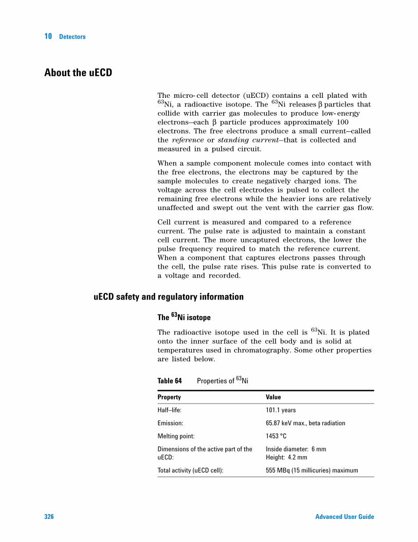
326 Advanced User Guide
10 Detectors
About the uECD
The micro- cell detector (uECD) contains a cell plated with 63Ni, a radioactive isotope. The 63Ni releases β particles that collide with carrier gas molecules to produce low- energy electrons—each β particle produces approximately 100 electrons. The free electrons produce a small current—called the reference or standing current—that is collected and measured in a pulsed circuit.
When a sample component molecule comes into contact with the free electrons, the electrons may be captured by the sample molecules to create negatively charged ions. The voltage across the cell electrodes is pulsed to collect the remaining free electrons while the heavier ions are relatively unaffected and swept out the vent with the carrier gas flow.
Cell current is measured and compared to a reference current. The pulse rate is adjusted to maintain a constant cell current. The more uncaptured electrons, the lower the pulse frequency required to match the reference current. When a component that captures electrons passes through the cell, the pulse rate rises. This pulse rate is converted to a voltage and recorded.
uECD safety and regulatory information
The 63Ni isotope
The radioactive isotope used in the cell is 63Ni. It is plated onto the inner surface of the cell body and is solid at temperatures used in chromatography. Some other properties are listed below.
Table 64 Properties of 63Ni
Property Value
Half–life: 101.1 years
Emission: 65.87 keV max., beta radiation
Melting point: 1453 °C
Dimensions of the active part of the uECD:
Inside diameter: 6 mm Height: 4.2 mm
Total activity (uECD cell): 555 MBq (15 millicuries) maximum
Detectors 10
Advanced User Guide 327
uECD licenses
Customers in the United states can purchase an exempt model uECD. Customers outside the United States should contact their local Agilent sales office for information.
uECD warnings
Although beta particles at this energy level have little penetrating power —the surface layer of the skin or a few sheets of paper will stop most of them—they may be hazardous if the isotope is ingested or inhaled. For this reason the cell must be handled with care: Radioactive leak tests must be performed at the required intervals (not applicable to exempt models), the inlet and outlet fittings must be capped when the detector is not in use, corrosive chemicals must not be introduced into the detector, and the effluent from the detector must be vented outside the laboratory environment.
• After turning off the main power and allowing the instrument to cool, cap the detector inlet and exhaust vent openings. Wear disposable plastic gloves and observe normal laboratory safety precautions.
• Return the cell for exchange, following directions included with the License Verification Form (part no. 19233- 90750).
WARNING Materials that may react with the 63Ni source, either to form volatile products or to cause physical degradation of the plated film, must be avoided. These materials include oxidizing compounds, acids, wet halogens, wet nitric acid, ammonium hydroxide, hydrogen sulfide, PCBs, and carbon monoxide. This list is not exhaustive but indicates the kinds of compounds that may cause damage to 63Ni detectors.
WARNING In the extremely unlikely event that both the oven and the detector heated zone should go into thermal runaway (maximum, uncontrolled heating in excess of 400 °C) at the same time, and that the detector remains exposed to this condition for more than 12 hours, take the following steps:
328 Advanced User Guide
10 Detectors
• Include a letter stating the condition of abuse.
It is unlikely, even in this very unusual situation, that radioactive material will escape the cell. However, permanent damage to the 63Ni plating within the cell is possible, and therefore, the cell must be returned for exchange.
Safety precautions when handling uECDs
• Never eat, drink, or smoke when handling uECDs.
• Always wear safety glasses when working with or near open uECDs.
• Wear protective clothing such as laboratory jackets, safety glasses, and gloves, and follow good laboratory practices. Wash hands thoroughly with a mild non- abrasive cleaner after handling uECDs.
• Cap the inlet and outlet fittings when the uECD is not in use.
• Connect the uECD exhaust vent to a fume hood or vent it to the outside. See the latest revision of title 10, Code of Federal Regulations, part 20, (including appendix B) or the applicable State regulation. For other countries, consult with the appropriate agency for equivalent requirements.
Agilent Technologies recommends a vent line inside diameter of 6 mm (1/4 inch) or greater. With a line of this diameter, the length is not critical.
WARNING Do not use solvents to clean the uECD.
WARNING You may not open the uECD cell unless authorized to do so by your local nuclear regulatory agency. Do not disturb the four socket-head bolts. These hold the cell halves together. United States customers removing or disturbing them is a violation of the terms of the exemption and could create a safety hazard.
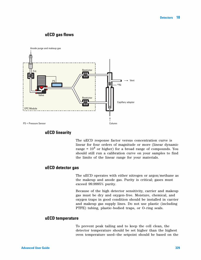
Detectors 10
Advanced User Guide 329
uECD gas flows
uECD linearity
The uECD response factor versus concentration curve is linear for four orders of magnitude or more (linear dynamic range = 104 or higher) for a broad range of compounds. You should still run a calibration curve on your samples to find the limits of the linear range for your materials.
uECD detector gas
The uECD operates with either nitrogen or argon/methane as the makeup and anode gas. Purity is critical; gases must exceed 99.9995% purity.
Because of the high detector sensitivity, carrier and makeup gas must be dry and oxygen- free. Moisture, chemical, and oxygen traps in good condition should be installed in carrier and makeup gas supply lines. Do not use plastic (including PTFE) tubing, plastic- bodied traps, or O- ring seals.
uECD temperature
To prevent peak tailing and to keep the cell clean, the detector temperature should be set higher than the highest oven temperature used—the setpoint should be based on the
PS = Pressure Sensor
PS
Valve
Frit
Restrictor
Restrictor
EPC Module
Anode purge and makeup gas
Vent63Ni
Column
Capillary adapter
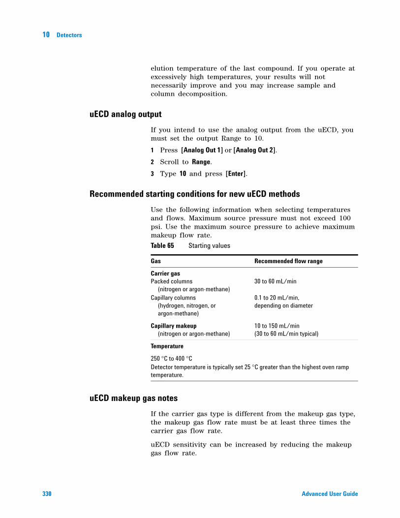
330 Advanced User Guide
10 Detectors
elution temperature of the last compound. If you operate at excessively high temperatures, your results will not necessarily improve and you may increase sample and column decomposition.
uECD analog output
If you intend to use the analog output from the uECD, you must set the output Range to 10.
1 Press [Analog Out 1] or [Analog Out 2].
2 Scroll to Range.
3 Type 10 and press [Enter].
Recommended starting conditions for new uECD methods
Use the following information when selecting temperatures and flows. Maximum source pressure must not exceed 100 psi. Use the maximum source pressure to achieve maximum makeup flow rate.
uECD makeup gas notes
If the carrier gas type is different from the makeup gas type, the makeup gas flow rate must be at least three times the carrier gas flow rate.
uECD sensitivity can be increased by reducing the makeup gas flow rate.
Table 65 Starting values
Gas Recommended flow range
Carrier gas Packed columns (nitrogen or argon-methane)Capillary columns (hydrogen, nitrogen, or argon-methane)
30 to 60 mL/min 0.1 to 20 mL/min, depending on diameter
Capillary makeup (nitrogen or argon-methane)
10 to 150 mL/min (30 to 60 mL/min typical)
Temperature
250 °C to 400 °CDetector temperature is typically set 25 °C greater than the highest oven ramp temperature.
Detectors 10
Advanced User Guide 331
uECD chromatographic speed (for fast peaks) can be increased by increasing the makeup gas flow rate.
uECD temperature programming
The uECD is flow sensitive. If you are using temperature programming, in which the column flow resistance changes with temperature, set up the instrument as follows:
• Set the carrier gas in the Constant flow mode. Set detector makeup gas to Constant makeup.
• If you choose to work in the constant pressure mode, the makeup gas should be set in the Column +makeup=constant mode.
Setting parameters for the uECD
Verify that your detector gases are connected, a column is properly installed, and the system is free of leaks. Set the oven temperature and the inlet temperature and flow. Make sure your carrier gas type is the same as that plumbed to your GC.
1 Press [Front Det] or [Back Det].
2 Set the detector temperature. To keep the uECD cell clean, this temperature must be higher than the oven temperature.
3 Verify that the makeup gas type is the same as that plumbed to your instrument. The gas type is in parentheses next to the Makeup line on the parameter list. Change the gas type, if necessary.
4 Enter a value for the makeup gas flow.
• If you are using packed columns, turn off the makeup gas.
• If your capillary column is defined, choose a flow mode and set the makeup or combined gas flow.
• If your capillary column is not defined, only constant makeup flow is available. Enter a makeup gas flow.
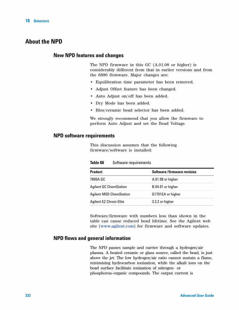
332 Advanced User Guide
10 Detectors
About the NPD
New NPD features and changes
The NPD firmware in this GC (A.01.08 or higher) is considerably different from that in earlier versions and from the 6890 firmware. Major changes are:
• Equilibration time parameter has been removed.
• Adjust Offset feature has been changed.
• Auto Adjust on/off has been added.
• Dry Mode has been added.
• Blos/ceramic bead selector has been added.
We strongly recommend that you allow the firmware to perform Auto Adjust and set the Bead Voltage.
NPD software requirements
This discussion assumes that the following firmware/software is installed:
Software/firmware with numbers less than shown in the table can cause reduced bead lifetime. See the Agilent web site (www.agilent.com) for firmware and software updates.
NPD flows and general information
The NPD passes sample and carrier through a hydrogen/air plasma. A heated ceramic or glass source, called the bead, is just above the jet. The low hydrogen/air ratio cannot sustain a flame, minimizing hydrocarbon ionization, while the alkali ions on the bead surface facilitate ionization of nitrogen- or phosphorus-organic compounds. The output current is
Table 66 Software requirements
Product Software/firmware revision
7890A GC A.01.08 or higher
Agilent GC ChemStation B.04.01 or higher
Agilent MSD ChemStation G1701EA or higher
Agilent EZ Chrom Elite 3.3.2 or higher
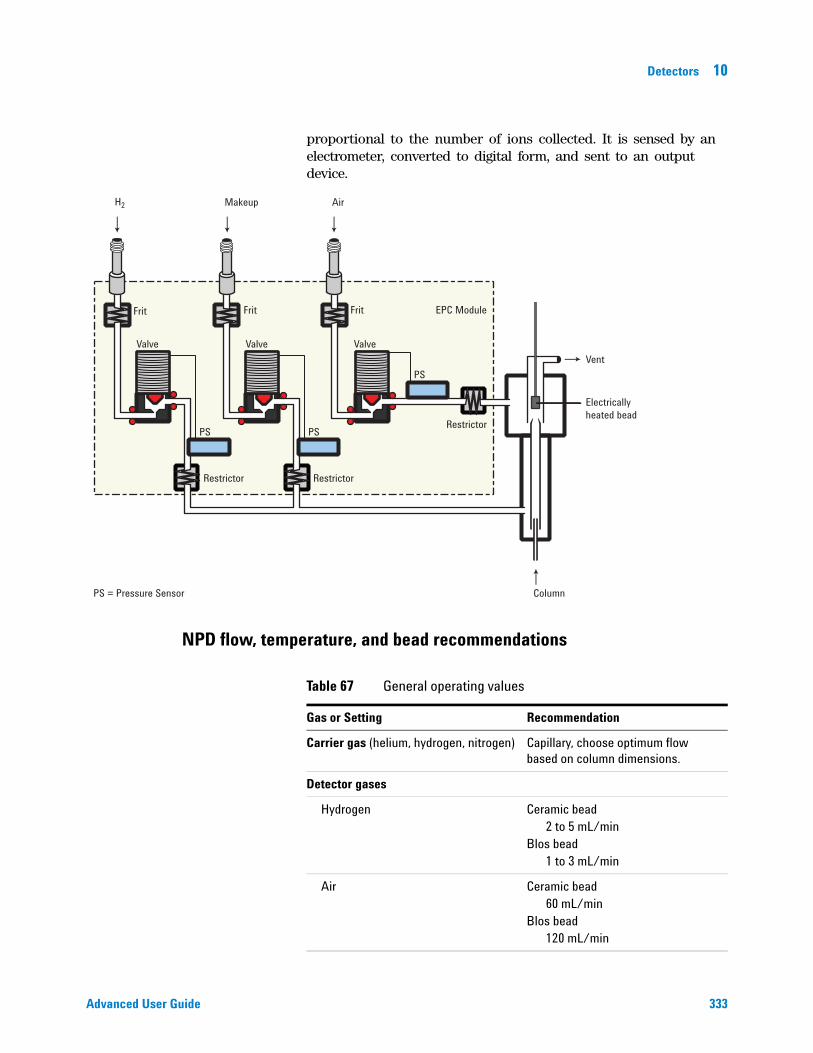
Detectors 10
Advanced User Guide 333
proportional to the number of ions collected. It is sensed by an electrometer, converted to digital form, and sent to an output device.
NPD flow, temperature, and bead recommendations
Valve
Frit Frit
Valve
PS = Pressure Sensor Column
PS
PS PS
Valve
Frit
Restrictor Restrictor
Restrictor
EPC Module
H2 Air
Vent
Electricallyheated bead
Makeup
Table 67 General operating values
Gas or Setting Recommendation
Carrier gas (helium, hydrogen, nitrogen) Capillary, choose optimum flow based on column dimensions.
Detector gases
Hydrogen Ceramic bead2 to 5 mL/min
Blos bead1 to 3 mL/min
Air Ceramic bead60 mL/min
Blos bead120 mL/min
334 Advanced User Guide
10 Detectors
Source gas pressures
Choose a flow, find a pressure, and set source pressure 10 psi (70 kPa) higher.
Capillary makeup (helium, nitrogen) Ceramic beadNitrogen: 5 to 10 mL/minHelium: less than 5 mL/min
Blos bead1 to 20 mL/min
Temperature Default is 250 °C; operating range is 150 °C to 400 °C.• <150 °C, the Adjust offset process will not start.• 325 to 335 °C is recommended.• Detector temperature should be greater than the highest oven temperature.
With higher detector temperatures, less bead heating voltage is required.
Adjust offset Default is 30 pA, suggested operating range is 20 to 40 pA, and allowable range is 0 to 99.9 pA.• ≥ 50 pA increases sensitivity but reduces bead life.• Lower settings reduce sensitivity and increase bead life, but settings too low
will result in solvent quenching.• The time required for Adjust offset depends on the bead type and condition.
Bead voltage Ceramic bead. Range is 0 to 4.095 V.Blos bead. Range is 0.5 to 1.1 V.• Use Auto Adjust On, Dry Bead, and let the GC set the Bead Voltage for you.
Table 67 General operating values (continued)
Gas or Setting Recommendation
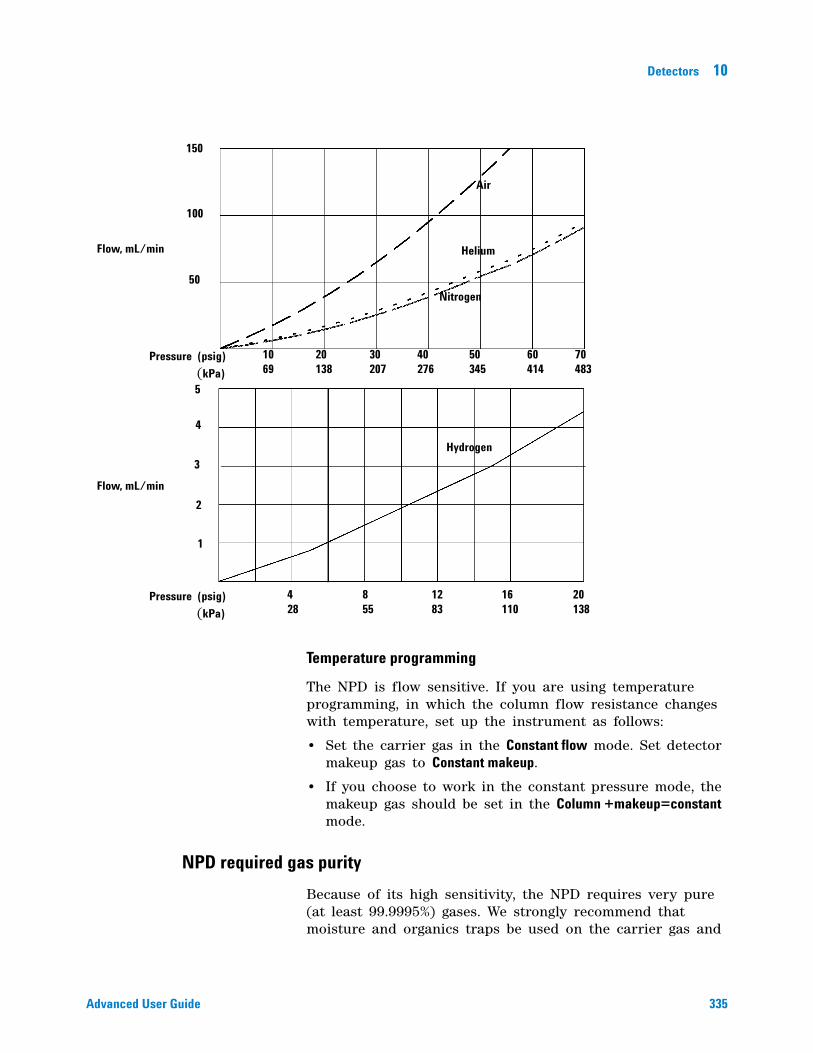
Detectors 10
Advanced User Guide 335
Temperature programming
The NPD is flow sensitive. If you are using temperature programming, in which the column flow resistance changes with temperature, set up the instrument as follows:
• Set the carrier gas in the Constant flow mode. Set detector makeup gas to Constant makeup.
• If you choose to work in the constant pressure mode, the makeup gas should be set in the Column +makeup=constant mode.
NPD required gas purity
Because of its high sensitivity, the NPD requires very pure (at least 99.9995%) gases. We strongly recommend that moisture and organics traps be used on the carrier gas and
Flow, mL/min
Flow, mL/min
Pressure (psig) (kPa)
Pressure (psig) (kPa)
50
100
150
5
4
3
2
1
Air
Helium
Nitrogen
Hydrogen
10 69
20 138
30 207
40 276
50 345
60 414
70 483
20 138
16 110
12 83
8 55
4 28
336 Advanced User Guide
10 Detectors
all detector gases, including the detector hydrogen, air, and makeup gases. Do not use plastic (including PTFE) tubing, plastic- bodied traps, or O- ring seals.
Setting parameters for the NPD
Before operating the NPD, make sure that detector gases are connected, a column is installed, and the system is free of leaks. Set the oven temperature, inlet temperature, and column flow.
1 Select the bead (white ceramic, black ceramic, Blos).
2 Select the jet.
3 Install bead and jet as required. (See the Maintenance Manual for details.)
4 Press [Config][Front Det] or [Config][Back Det].
5 If you are using makeup gas, verify that the configured makeup gas type is the same as that plumbed to your instrument. Change the gas type, if necessary. Nitrogen is recommended.
6 If the displayed Bead Type is incorrect, set the Bead Type using the [Mode/Type] key.
7 Set Auto Adjust (On recommended).
8 Set Dry Bead (On recommended).
9 Press [Front Det] or [Back Det].
10 Set the detector temperature. The recommended range is 325 to 335 °C.
11 Enter a hydrogen flow (3.0 mL/min is recommended). Turn the flow On.
12 Enter an air flow (60 is recommended for ceramic beads, 120 for Blos beads). Turn the flow On.
a If you are using packed columns, turn off makeup gas and proceed to step 13.
b If your capillary column is defined, choose a flow mode and set the makeup gas flow. For a column in the constant flow mode, choose Constant makeup. For a
WARNING Make sure that a column is installed or the NPD column fitting is plugged before turning on the air or hydrogen. An explosion may occur if air and hydrogen are allowed to leak into the oven.
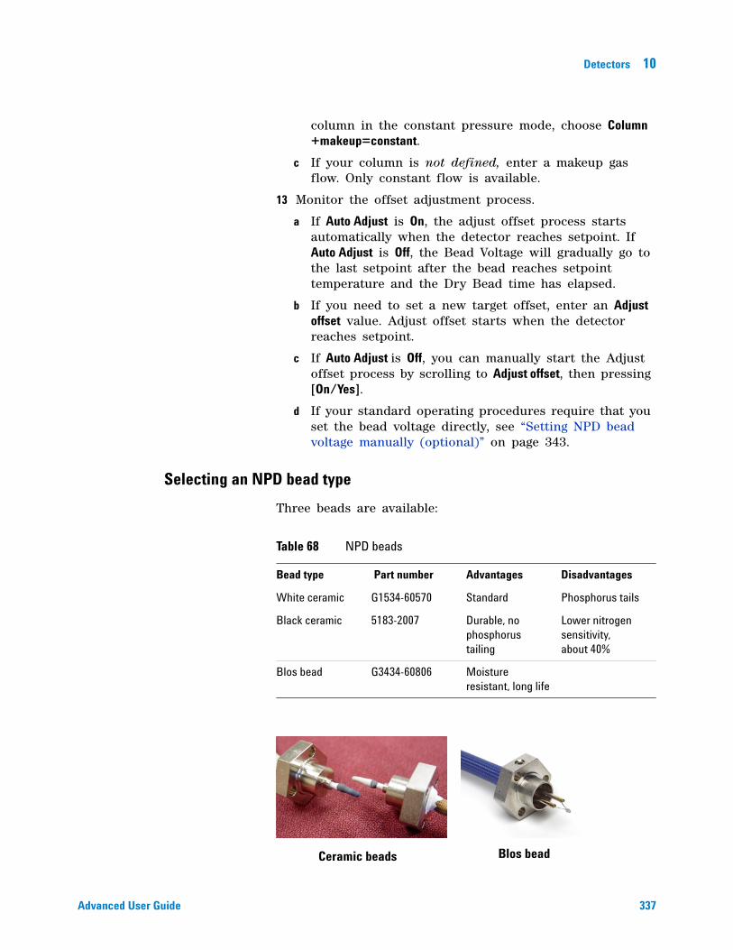
Detectors 10
Advanced User Guide 337
column in the constant pressure mode, choose Column +makeup=constant.
c If your column is not defined, enter a makeup gas flow. Only constant flow is available.
13 Monitor the offset adjustment process.
a If Auto Adjust is On, the adjust offset process starts automatically when the detector reaches setpoint. If Auto Adjust is Off, the Bead Voltage will gradually go to the last setpoint after the bead reaches setpoint temperature and the Dry Bead time has elapsed.
b If you need to set a new target offset, enter an Adjust offset value. Adjust offset starts when the detector reaches setpoint.
c If Auto Adjust is Off, you can manually start the Adjust offset process by scrolling to Adjust offset, then pressing [On/Yes].
d If your standard operating procedures require that you set the bead voltage directly, see “Setting NPD bead voltage manually (optional)” on page 343.
Selecting an NPD bead type
Three beads are available:
Table 68 NPD beads
Bead type Part number Advantages Disadvantages
White ceramic G1534-60570 Standard Phosphorus tails
Black ceramic 5183-2007 Durable, no phosphorus tailing
Lower nitrogen sensitivity, about 40%
Blos bead G3434-60806 Moisture resistant, long life
Ceramic beads Blos bead
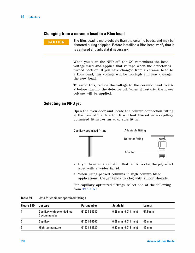
338 Advanced User Guide
10 Detectors
Changing from a ceramic bead to a Blos bead
When you turn the NPD off, the GC remembers the bead voltage used and applies that voltage when the detector is turned back on. If you have changed from a ceramic bead to a Blos bead, this voltage will be too high and may damage the new bead.
To avoid this, reduce the voltage to the ceramic bead to 0.5 V before turning the detector off. When it restarts, the lower voltage will be applied.
Selecting an NPD jet
Open the oven door and locate the column connection fitting at the base of the detector. It will look like either a capillary optimized fitting or an adaptable fitting.
• If you have an application that tends to clog the jet, select a jet with a wider tip id.
• When using packed columns in high column- bleed applications, the jet tends to clog with silicon dioxide.
For capillary optimized fittings, select one of the following from Table 69.
CAUTION The Blos bead is more delicate than the ceramic beads, and may be distorted during shipping. Before installing a Blos bead, verify that it is centered and adjust it if necessary.
Capillary optimized fitting Adaptable fitting
Detector fitting
Adapter
Table 69 Jets for capillary optimized fittings
Figure 3 ID Jet type Part number Jet tip id Length
1 Capillary with extended jet (recommended)
G1534-80580 0.29 mm (0.011 inch) 51.5 mm
2 Capillary G1531-80560 0.29 mm (0.011 inch) 43 mm
3 High-temperature G1531-80620 0.47 mm (0.018 inch) 43 mm
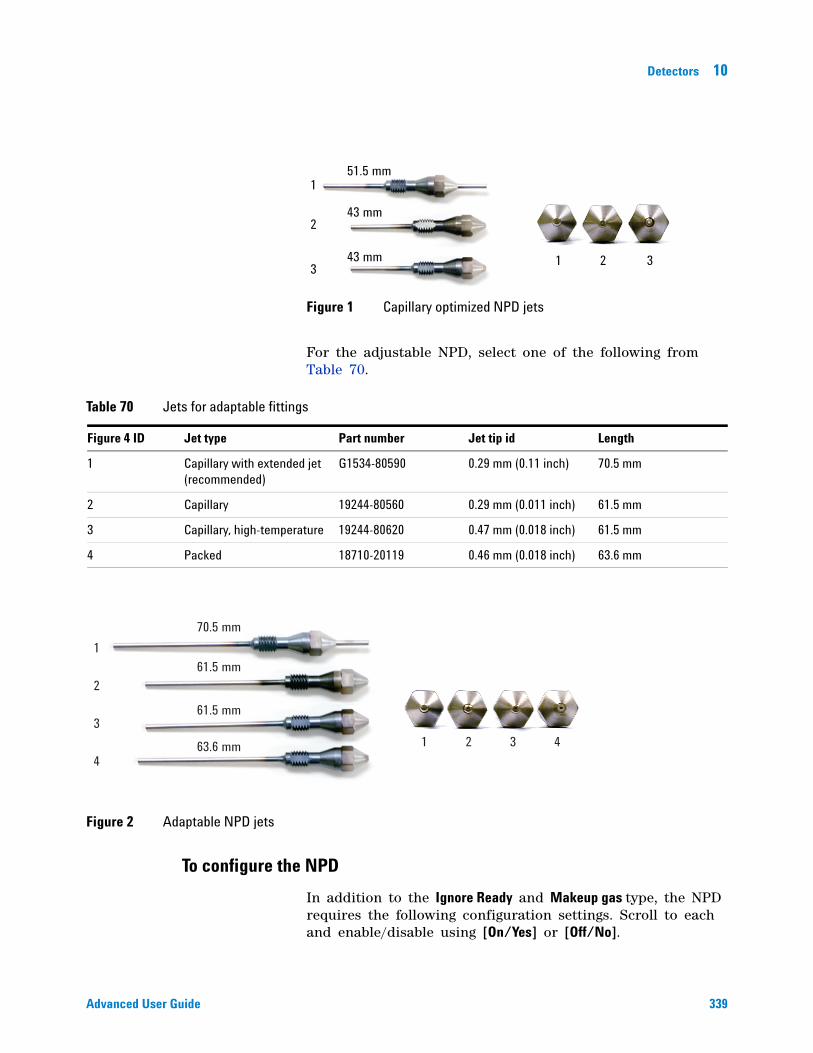
Detectors 10
Advanced User Guide 339
For the adjustable NPD, select one of the following from Table 70.
To configure the NPD
In addition to the Ignore Ready and Makeup gas type, the NPD requires the following configuration settings. Scroll to each and enable/disable using [On/Yes] or [Off/No].
Figure 1 Capillary optimized NPD jets
1
2
3 1 2 3
43 mm
51.5 mm
43 mm
Table 70 Jets for adaptable fittings
Figure 4 ID Jet type Part number Jet tip id Length
1 Capillary with extended jet (recommended)
G1534-80590 0.29 mm (0.11 inch) 70.5 mm
2 Capillary 19244-80560 0.29 mm (0.011 inch) 61.5 mm
3 Capillary, high-temperature 19244-80620 0.47 mm (0.018 inch) 61.5 mm
4 Packed 18710-20119 0.46 mm (0.018 inch) 63.6 mm
Figure 2 Adaptable NPD jets
1
2
3
41 2 3 4
70.5 mm
61.5 mm
61.5 mm
63.6 mm
340 Advanced User Guide
10 Detectors
Auto Adjust Bead Recommended On. When On, the automatic adjust offset process starts when the bead reaches the temperature setpoint after having been turned off or cooled below 150 °C. Auto adjust starts after Dry Bead hold time, if enabled. Auto Adjust Bead uses the adjust offset feature to protect the bead—especially new beads—by making sure that the desired offset is obtained with the lowest possible bead voltage. When Off, the bead voltage will rise as soon as the Dry Bead time elapses, or as soon as the temperature setpoint is reached if Dry Bead is off.
Dry Bead Recommended On. When On, the bead temperature holds at 150 °C for 5 minutes before continuing to the setpoint. This allows any condensation to evaporate and be swept out of the detector.
Blos Bead If using a Blos bead, set to On. For ceramic beads, set to Off. The Blos Bead On setting restricts the allowable bead voltage to the range appropriate for this bead.
Maximum Bead Voltage Display only. Shows the current maximum bead voltage for the configured bead type (4.095 V for ceramic beads, 1.1 V for the Blos bead).
Automatically adjusting NPD bead voltage
Agilent recommends using the Adjust offset feature to automatically determine the lowest bead voltage needed to give the desired response.
When the detector is turned on, the temperature rises at a controlled rate.
• If Dry Bead is On, temperature holds at 150 °C for 5 minutes to drive off moisture, then continues to the setpoint.
• If Dry Bead is Off, the temperature rises directly to the setpoint.
When the temperature reaches the setpoint, the Bead Voltage gradually rises until it produces the desired output.
Adjust offset
When you enter a value here, or press [On/Yes] to use the stored value, detector gas flows turn on, the bead heats, and the bead voltage adjusts until Output is stable and equal to the entered value. There are five stages of Adjust offset.
Detectors 10
Advanced User Guide 341
Detector off When the detector is off, Adjust offset and Bead voltage are Off and initial Output is displayed.
Detector on—detector temperature less than 150 °C. When you enter an Adjust offset value or press [On], detector gases turn on and the display blinks the Temp not ready message.
Detector on—waiting for oven and/or detector to reach temperature setpoint and equilibrium. If the oven or detector is not at setpoint, the display continues to blink the Temp not ready message.
Detector on—Dry Bead On If Dry Bead is On, the temperature rise holds at 150 °C for 5 minutes to remove moisture, then continues to the setpoint.
Detector on—during adjust offset. When the detector and oven temperatures reach setpoint and equilibrate, the Adjust offset process begins. The bead voltage is slowly increased until the output is close to the Adjust offset value. The display blinks Detector Slewing.
Detector on and ready. When the Adjust offset value is reached, the Adjust offset line reads Done and displays the offset target setpoint. Your detector is on and ready. The display shows the actual Bead voltage.
Setting NPD adjust offset on the clock table
You can use the Clock table feature to begin Adjust offset at a specified time.
Aborting NPD adjust offset
Press [Delete] with the cursor on the Adjust offset line. This cancels the adjustment without turning off the detector gases and bead voltage.
Extending the NPD bead life
These actions, together with the automated heatup and adjust procedures, can extend ceramic bead life considerably.
• Use the lowest practical Adjust offset value. This will result in a lower Bead Voltage during operation.
• Run clean samples.
• Turn the bead off when not in use.
342 Advanced User Guide
10 Detectors
• Keep the detector temperature high (320 to 335 °C).
• Turn the hydrogen flow off during solvent peaks and between runs.
Turning hydrogen off during a solvent peak
When using the NPD, the baseline shifts after a solvent peak and can take some time to stabilize, especially with chlorinated solvents. To minimize this effect, turn off the hydrogen flow during the solvent peak and turn it back on after the solvent elutes. With this technique, the baseline recovers to its original value in less than 30 seconds. This also extends the life of the bead. The hydrogen can be turned on and off automatically as part of a Run Table. See “Run Time Programming” on page 16.
Turning hydrogen off between runs
To extend bead life, turn off the hydrogen flow between runs. Leave all other flows and the detector temperature on. Turn on the hydrogen flow for the next run; the bead will ignite almost immediately. The process can be automated with Run Table entries.
Turning off the detector
Setting the initial bead voltage for new beads
Before you turn on the bead for the first time, manually set its voltage to a safe value so that the new bead is not destroyed.
1 Make sure Adjust Offset is turned Off.
2 After the temperature stabilizes at setpoint, set the initial Bead Voltage, depending on bead type:
• Blos bead: 0.0 V to 0.5 V
• Ceramic bead (white or black): 0.0 V to 2.0 V
CAUTION If you turn Adjust offset [Off] at any time, the bead voltage, hydrogen, and air flows all turn off.
Detectors 10
Advanced User Guide 343
Setting NPD bead voltage manually (optional)
Bead voltage shows the voltage used to heat the bead. It can be a value derived from the Adjust offset value, or can be entered as a setpoint. Entering a setpoint causes the voltage to change at 13 mV/second until it reaches the setpoint provided that
• the detector is at the temperature setpoint
• temperature is at least 150 °C
• gas flows are on
• Dry Bead time, if On, has elapsed
Bead voltage is also useful for small adjustments between runs. If you observe a baseline drift, you can enter a small, one- time change to compensate for the drift.
If you are not using the recommended Adjust offset process, note that large voltage jumps reduce bead life. Use increments no greater than 0.05 V, spaced 10 seconds apart, until you reach the desired offset.
New beads
After a new bead reaches the initial voltage, begin to increase the voltage value in 0.05 V increments until the bead ignites. Wait about 10 seconds between each voltage adjustment. Monitor the detector output. When the bead ignites, the output will rise suddenly, then decrease towards a more stable value. It is best to allow the NPD to remain in this state without further adjustment for about 24 hours. Then you may adjust the bead voltage in small increments (0.05 to 0.1 V) until reaching the desired offset. With a clean environment, clean gas supplies, and low bleed column, a typical offset may decrease 6- 12 pA during a 24 hour period.
Typical voltages for new ceramic beads range from 2.5 to 3.7 volts. Higher values reduce bead life.
Typical voltages for new Blos beads range from 0.5 to 1.0 V.
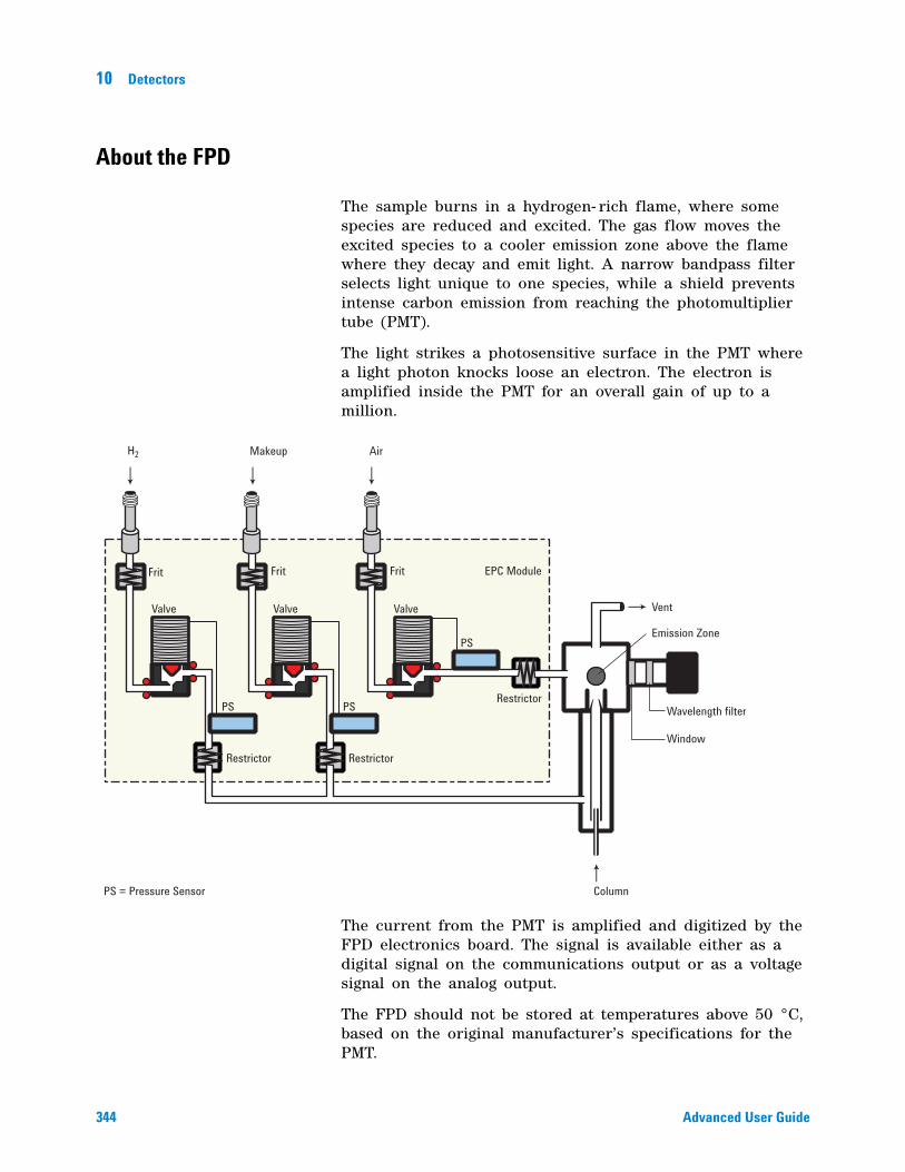
344 Advanced User Guide
10 Detectors
About the FPD
The sample burns in a hydrogen- rich flame, where some species are reduced and excited. The gas flow moves the excited species to a cooler emission zone above the flame where they decay and emit light. A narrow bandpass filter selects light unique to one species, while a shield prevents intense carbon emission from reaching the photomultiplier tube (PMT).
The light strikes a photosensitive surface in the PMT where a light photon knocks loose an electron. The electron is amplified inside the PMT for an overall gain of up to a million.
The current from the PMT is amplified and digitized by the FPD electronics board. The signal is available either as a digital signal on the communications output or as a voltage signal on the analog output.
The FPD should not be stored at temperatures above 50 °C, based on the original manufacturer’s specifications for the PMT.
Valve
Frit Frit
Valve
PS = Pressure Sensor Column
PS
PS PS
Valve
Frit
Restrictor Restrictor
Restrictor
EPC Module
H2 Air
Wavelength filter
Window
Vent
Makeup
Emission Zone
Detectors 10
Advanced User Guide 345
FPD linearity
Several mechanisms produce sulfur emission. The excited species is diatomic, so that emission intensity is approximately proportional to the square of the sulfur atom concentration.
The excited species in the phosphorus mode is monatomic, leading to a linear relationship between emission intensity and atom concentration.
FPD Lit Offset
The default Lit Offset is 2.0 pA.
Starting Up and Shutting Down the FPD
The FPD creates a great deal of water vapor when the flame is on. This could condense in the vent tube on top of the detector and drop onto the flame, possibly extinguishing it. To avoid this, turn the heaters on, wait 20 minutes for the vent to heat up, and then ignite the flame. Water vapor will now make it over the top of the vent tube before condensing.
For similar reasons, extinguish the flame before turning the heaters off.
FPD photomultiplier protection
The PMT is extremely sensitive to light. Always turn the PMT voltage off (which turns off the high voltage to the PMT) before removing the PMT housing or opening the emissions chamber. Failing to do this can destroy the PMT.
Even with the PMT voltage off, protect the PMT from room light. Cap the housing when removed, place it end down to exclude light, reduce room light level before exposing the PMT, and so on. A brief exposure (always with the PMT voltage turned off) will not damage it but prolonged exposure will cause a gradual loss of sensitivity.
FPD optical filters
The filters are marked on the edge with the transmission wavelength. Each filter has a small arrow on its side which must point toward the PMT when installed.
The sulfur filter is silvery on both sides and transmits at 393 nanometers.
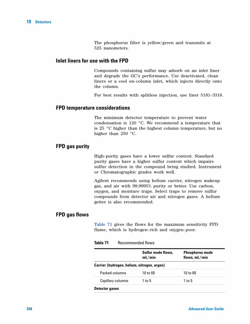
346 Advanced User Guide
10 Detectors
The phosphorus filter is yellow/green and transmits at 525 nanometers.
Inlet liners for use with the FPD
Compounds containing sulfur may adsorb on an inlet liner and degrade the GC’s performance. Use deactivated, clean liners or a cool on- column inlet, which injects directly onto the column.
For best results with splitless injection, use liner 5181- 3316.
FPD temperature considerations
The minimum detector temperature to prevent water condensation is 120 °C. We recommend a temperature that is 25 °C higher than the highest column temperature, but no higher than 250 °C.
FPD gas purity
High- purity gases have a lower sulfur content. Standard purity gases have a higher sulfur content which impairs sulfur detection in the compound being studied. Instrument or Chromatographic grades work well.
Agilent recommends using helium carrier, nitrogen makeup gas, and air with 99.9995% purity or better. Use carbon, oxygen, and moisture traps. Select traps to remove sulfur compounds from detector air and nitrogen gases. A helium getter is also recommended.
FPD gas flows
Table 71 gives the flows for the maximum sensitivity FPD flame, which is hydrogen- rich and oxygen- poor.
Table 71 Recommended flows
Sulfur mode flows, mL/min
Phosphorus mode flows, mL/min
Carrier (hydrogen, helium, nitrogen, argon)
Packed columns 10 to 60 10 to 60
Capillary columns 1 to 5 1 to 5
Detector gases
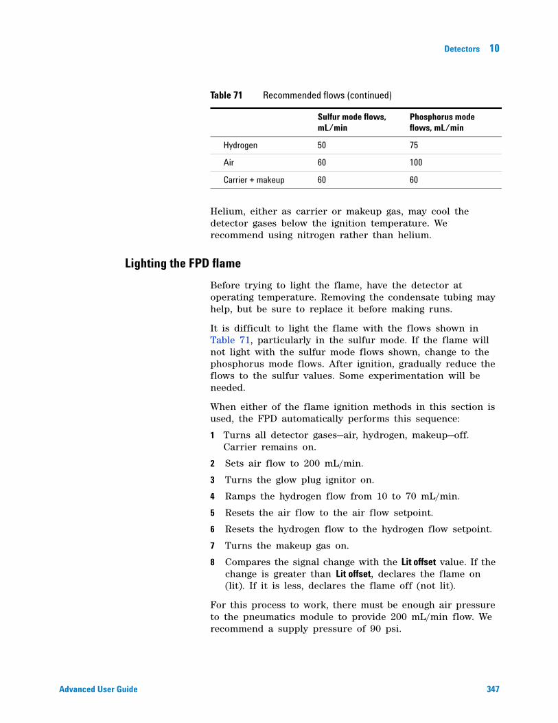
Detectors 10
Advanced User Guide 347
Helium, either as carrier or makeup gas, may cool the detector gases below the ignition temperature. We recommend using nitrogen rather than helium.
Lighting the FPD flame
Before trying to light the flame, have the detector at operating temperature. Removing the condensate tubing may help, but be sure to replace it before making runs.
It is difficult to light the flame with the flows shown in Table 71, particularly in the sulfur mode. If the flame will not light with the sulfur mode flows shown, change to the phosphorus mode flows. After ignition, gradually reduce the flows to the sulfur values. Some experimentation will be needed.
When either of the flame ignition methods in this section is used, the FPD automatically performs this sequence:
1 Turns all detector gases—air, hydrogen, makeup—off. Carrier remains on.
2 Sets air flow to 200 mL/min.
3 Turns the glow plug ignitor on.
4 Ramps the hydrogen flow from 10 to 70 mL/min.
5 Resets the air flow to the air flow setpoint.
6 Resets the hydrogen flow to the hydrogen flow setpoint.
7 Turns the makeup gas on.
8 Compares the signal change with the Lit offset value. If the change is greater than Lit offset, declares the flame on (lit). If it is less, declares the flame off (not lit).
For this process to work, there must be enough air pressure to the pneumatics module to provide 200 mL/min flow. We recommend a supply pressure of 90 psi.
Hydrogen 50 75
Air 60 100
Carrier + makeup 60 60
Table 71 Recommended flows (continued)
Sulfur mode flows, mL/min
Phosphorus mode flows, mL/min
348 Advanced User Guide
10 Detectors
Manual ignition
1 Press [Front Det] or [Back Det].
2 Scroll to Flame. Press [On/Yes]. The flame ignition sequence begins.
Automatic ignition
If the FPD output with the flame on falls below the flame- off output plus the Lit offset value, this is interpreted as a flame- out condition. The FPD runs the flame ignition sequence to relight the flame. If this fails, it runs the sequence again. If the second attempt also fails, the detector shuts down all functions except temperature and makeup gas flow.
Setting parameters for the FPD
1 Press [Front det] or [Back det].
2 Set the detector temperature. It must be greater than 120 °C for the flame to light.
3 Change the hydrogen flow rate, if desired. Press [Off/No].
4 Change the air flow rate, if desired. Press [Off/No].
5 If you are using packed columns, turn off the makeup gas and proceed to step 7.
6 If you are using capillary columns:
a Verify that makeup gas type is the same as that plumbed to your instrument (next to Makeup in the parameter list). Change the gas type, if necessary.
b If your capillary column is defined, choose a flow mode and set the makeup gas flow or combined flow.
c If your capillary column is not defined, enter a makeup gas flow. Only constant flow is available.
7 Scroll to Flame and press [On/Yes]. This turns on the air and hydrogen and initiates the ignition sequence.
On ignition, the signal increases. Typical levels are 4 to 40 pA in sulfur mode, 10 to 70 pA in phosphorus mode. Verify that the flame is lit by holding a cold, shiny
WARNING Verify that a column is installed or the FPD fitting is plugged before turning on the air or hydrogen. An explosion may occur if air and hydrogen are allowed to leak into the oven.

Detectors 10
Advanced User Guide 349
surface, such as a mirror or chrome- plated wrench, over the vent exit. Steady condensation indicates that the flame is lit.

350 Advanced User Guide
10 Detectors
351
Agilent 7890A Gas ChromatographAdvanced User Guide
Agilent Technologies
11Valves
About Valves 352
The Valve Box 353
Heating the valves 353
Valve temperature programming 353
Configuring an Aux thermal zone 354
Valve Control 355
The valve drivers 355
The internal valve drivers 355
The external valve drivers 356
Valve Types 357
Configuring a Valve 358
Controlling a Valve 359
From the keyboard 359
From the run or clock time tables 359
Simple valve: column selection 359
Gas sampling valve 360
Multiposition stream selection valve with sampling valve 361
352 Advanced User Guide
11 Valves
About Valves
Valves may be used to alter the usual inlet/column/detector flow path in the GC. Sampling valves can replace the inlet, switching valves can select columns, multiposition valves, used in conjunction with sampling valves, can perform the same functions for sample streams that an ALS performs for liquid samples.
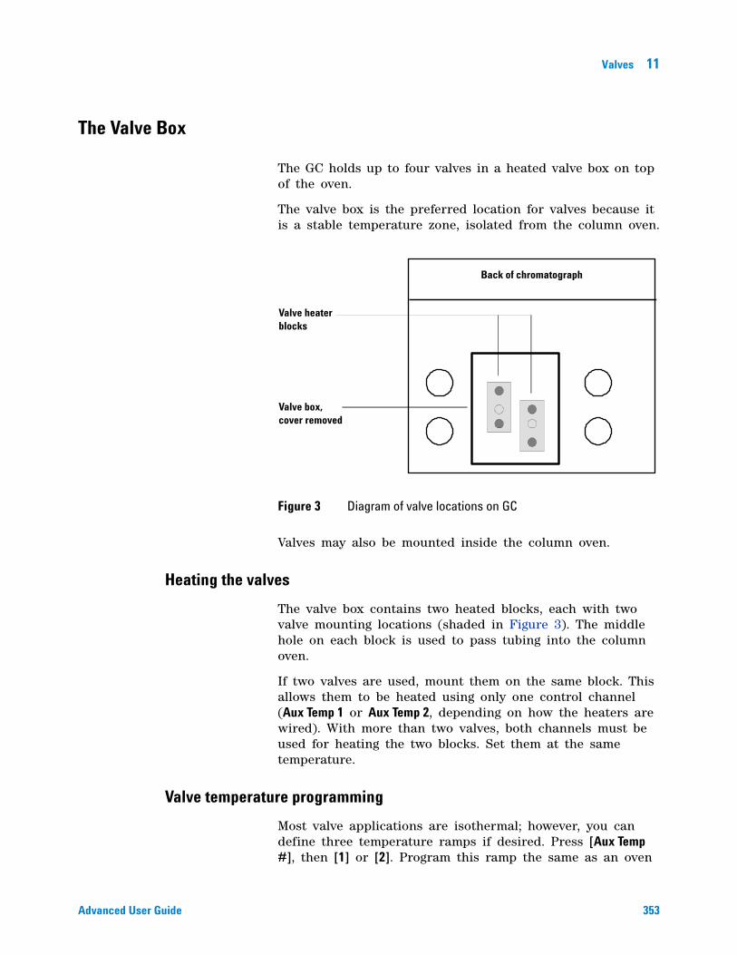
Valves 11
Advanced User Guide 353
The Valve Box
The GC holds up to four valves in a heated valve box on top of the oven.
The valve box is the preferred location for valves because it is a stable temperature zone, isolated from the column oven.
Valves may also be mounted inside the column oven.
Heating the valves
The valve box contains two heated blocks, each with two valve mounting locations (shaded in Figure 3). The middle hole on each block is used to pass tubing into the column oven.
If two valves are used, mount them on the same block. This allows them to be heated using only one control channel (Aux Temp 1 or Aux Temp 2, depending on how the heaters are wired). With more than two valves, both channels must be used for heating the two blocks. Set them at the same temperature.
Valve temperature programming
Most valve applications are isothermal; however, you can define three temperature ramps if desired. Press [Aux Temp #], then [1] or [2]. Program this ramp the same as an oven
Figure 3 Diagram of valve locations on GC
Valve heater blocks
Valve box, cover removed
Back of chromatograph
354 Advanced User Guide
11 Valves
ramp. Refer to “Setting the oven parameters for ramped temperature” on page 296 for more information.
Configuring an Aux thermal zone
To configure a thermal Aux zone (1 or 2), press [Config][Aux Temp #], then [1] or [2]. Press [Mode/Type], then select the type of device to be controlled. Press [Enter].
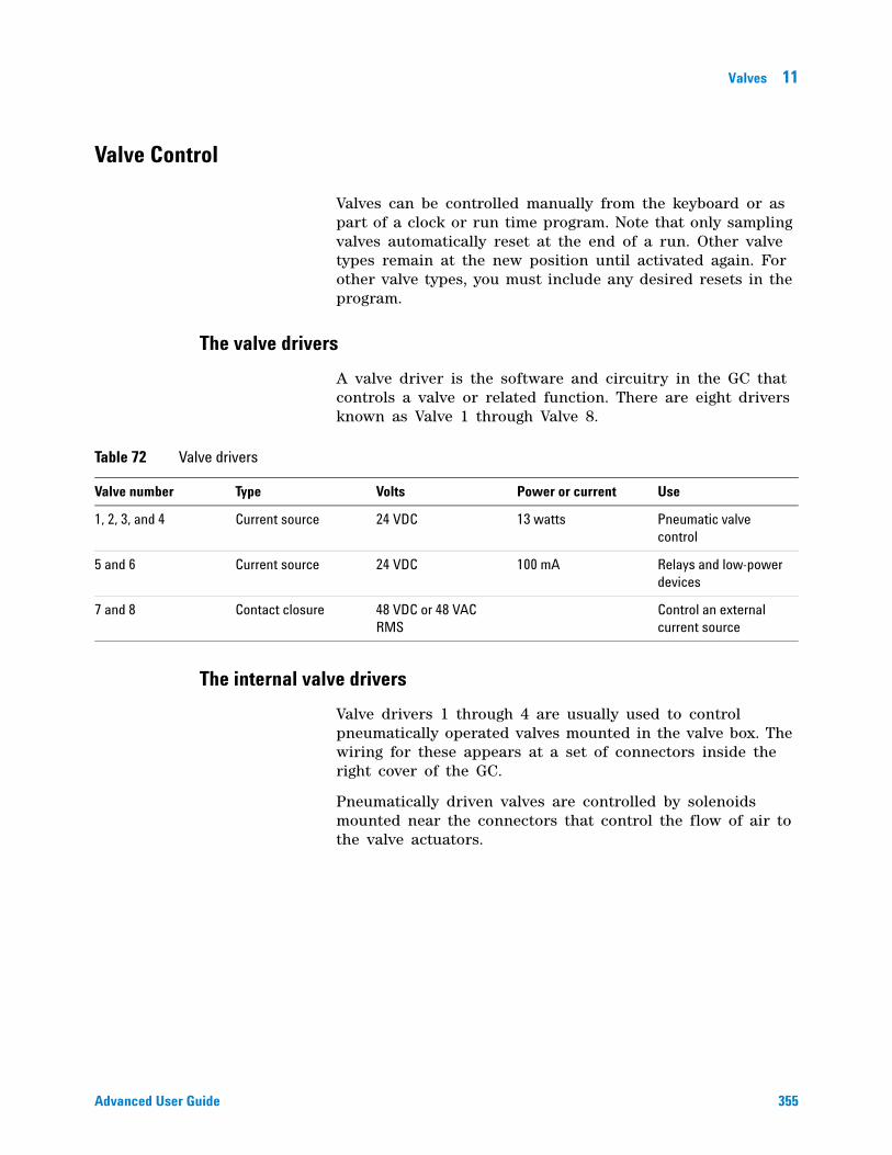
Valves 11
Advanced User Guide 355
Valve Control
Valves can be controlled manually from the keyboard or as part of a clock or run time program. Note that only sampling valves automatically reset at the end of a run. Other valve types remain at the new position until activated again. For other valve types, you must include any desired resets in the program.
The valve drivers
A valve driver is the software and circuitry in the GC that controls a valve or related function. There are eight drivers known as Valve 1 through Valve 8.
The internal valve drivers
Valve drivers 1 through 4 are usually used to control pneumatically operated valves mounted in the valve box. The wiring for these appears at a set of connectors inside the right cover of the GC.
Pneumatically driven valves are controlled by solenoids mounted near the connectors that control the flow of air to the valve actuators.
Table 72 Valve drivers
Valve number Type Volts Power or current Use
1, 2, 3, and 4 Current source 24 VDC 13 watts Pneumatic valve control
5 and 6 Current source 24 VDC 100 mA Relays and low-power devices
7 and 8 Contact closure 48 VDC or 48 VAC RMS
Control an external current source
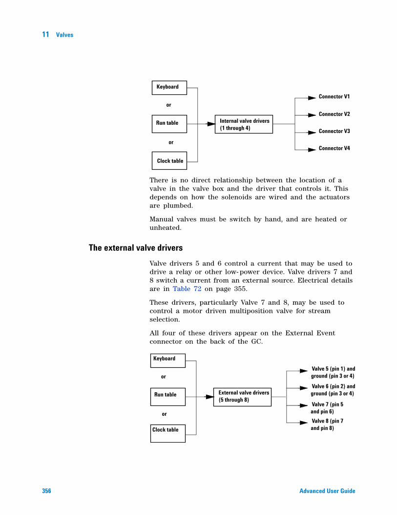
356 Advanced User Guide
11 Valves
There is no direct relationship between the location of a valve in the valve box and the driver that controls it. This depends on how the solenoids are wired and the actuators are plumbed.
Manual valves must be switch by hand, and are heated or unheated.
The external valve drivers
Valve drivers 5 and 6 control a current that may be used to drive a relay or other low- power device. Valve drivers 7 and 8 switch a current from an external source. Electrical details are in Table 72 on page 355.
These drivers, particularly Valve 7 and 8, may be used to control a motor driven multiposition valve for stream selection.
All four of these drivers appear on the External Event connector on the back of the GC.
Internal valve drivers (1 through 4)
Keyboard
Run table
Clock table
or
or
Connector V1
Connector V2
Connector V3
Connector V4
Keyboard
Run table
Clock table
or
or
External valve drivers (5 through 8)
Valve 5 (pin 1) andground (pin 3 or 4)
Valve 6 (pin 2) andground (pin 3 or 4)
Valve 7 (pin 5 and pin 6)
Valve 8 (pin 7 and pin 8)
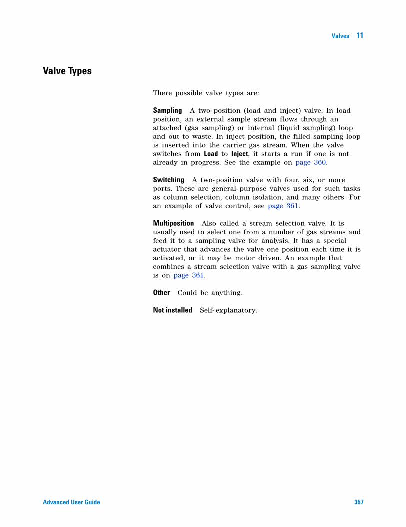
Valves 11
Advanced User Guide 357
Valve Types
There possible valve types are:
Sampling A two- position (load and inject) valve. In load position, an external sample stream flows through an attached (gas sampling) or internal (liquid sampling) loop and out to waste. In inject position, the filled sampling loop is inserted into the carrier gas stream. When the valve switches from Load to Inject, it starts a run if one is not already in progress. See the example on page 360.
Switching A two- position valve with four, six, or more ports. These are general- purpose valves used for such tasks as column selection, column isolation, and many others. For an example of valve control, see page 361.
Multiposition Also called a stream selection valve. It is usually used to select one from a number of gas streams and feed it to a sampling valve for analysis. It has a special actuator that advances the valve one position each time it is activated, or it may be motor driven. An example that combines a stream selection valve with a gas sampling valve is on page 361.
Other Could be anything.
Not installed Self- explanatory.
358 Advanced User Guide
11 Valves
Configuring a Valve
1 Press [Config]. Scroll to Valve #.
2 Enter the valve number and press [Enter]. The current valve type is displayed.
3 To change the valve type, press [Mode/Type], select the new valve type, and press [Enter].
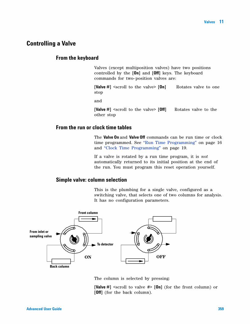
Valves 11
Advanced User Guide 359
Controlling a Valve
From the keyboard
Valves (except multiposition valves) have two positions controlled by the [On] and [Off] keys. The keyboard commands for two- position valves are:
[Valve #] <scroll to the valve> [On] Rotates valve to one stop
and
[Valve #] <scroll to the valve> [Off] Rotates valve to the other stop
From the run or clock time tables
The Valve On and Valve Off commands can be run time or clock time programmed. See “Run Time Programming” on page 16 and “Clock Time Programming” on page 19.
If a valve is rotated by a run time program, it is not automatically returned to its initial position at the end of the run. You must program this reset operation yourself.
Simple valve: column selection
This is the plumbing for a single valve, configured as a switching valve, that selects one of two columns for analysis. It has no configuration parameters.
The column is selected by pressing:
[Valve #] <scroll to valve #> [On] (for the front column) or [Off] (for the back column).
Front column
Back column
To detector
From inlet or sampling valve
ON OFF
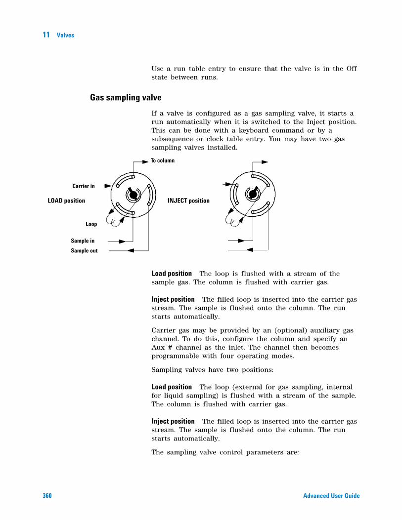
360 Advanced User Guide
11 Valves
Use a run table entry to ensure that the valve is in the Off state between runs.
Gas sampling valve
If a valve is configured as a gas sampling valve, it starts a run automatically when it is switched to the Inject position. This can be done with a keyboard command or by a subsequence or clock table entry. You may have two gas sampling valves installed.
Load position The loop is flushed with a stream of the sample gas. The column is flushed with carrier gas.
Inject position The filled loop is inserted into the carrier gas stream. The sample is flushed onto the column. The run starts automatically.
Carrier gas may be provided by an (optional) auxiliary gas channel. To do this, configure the column and specify an Aux # channel as the inlet. The channel then becomes programmable with four operating modes.
Sampling valves have two positions:
Load position The loop (external for gas sampling, internal for liquid sampling) is flushed with a stream of the sample. The column is flushed with carrier gas.
Inject position The filled loop is inserted into the carrier gas stream. The sample is flushed onto the column. The run starts automatically.
The sampling valve control parameters are:
Carrier in
To column
Sample in
Sample out
LOAD position INJECT position
Loop
Valves 11
Advanced User Guide 361
Load time Time in minutes that the valve remains in the Load position before becoming ready.
Inject time Time in minutes that the valve remains in the Inject position before returning to the Load position.
The sampling valve cycle is:
1 The sampling valve rotates to the Load position. Load time begins. Valve is not ready.
2 Load time ends. The valve becomes ready.
3 If everything else is ready, the GC becomes ready. If anything is not ready:
• If you are using Clock Table or sequence control, the GC waits until everything is ready, then executes the valve inject command.
• If you are not using Clock Table or sequence control, the valve injection can be made at any time from the keyboard.
4 The sampling valve rotates (keyboard command or sequence control) to the Inject position. Inject time begins. The run begins.
5 Inject time ends. Return to step 1.
Multiposition stream selection valve with sampling valve
Several manufacturers provide multiposition stream selection valves that can be driven by valve drivers 1 through 4. Only one multiposition valve can be configured.
If a valve is configured as a multiposition valve and has a BCD position output connected to the GC, the valve position can be selected directly.
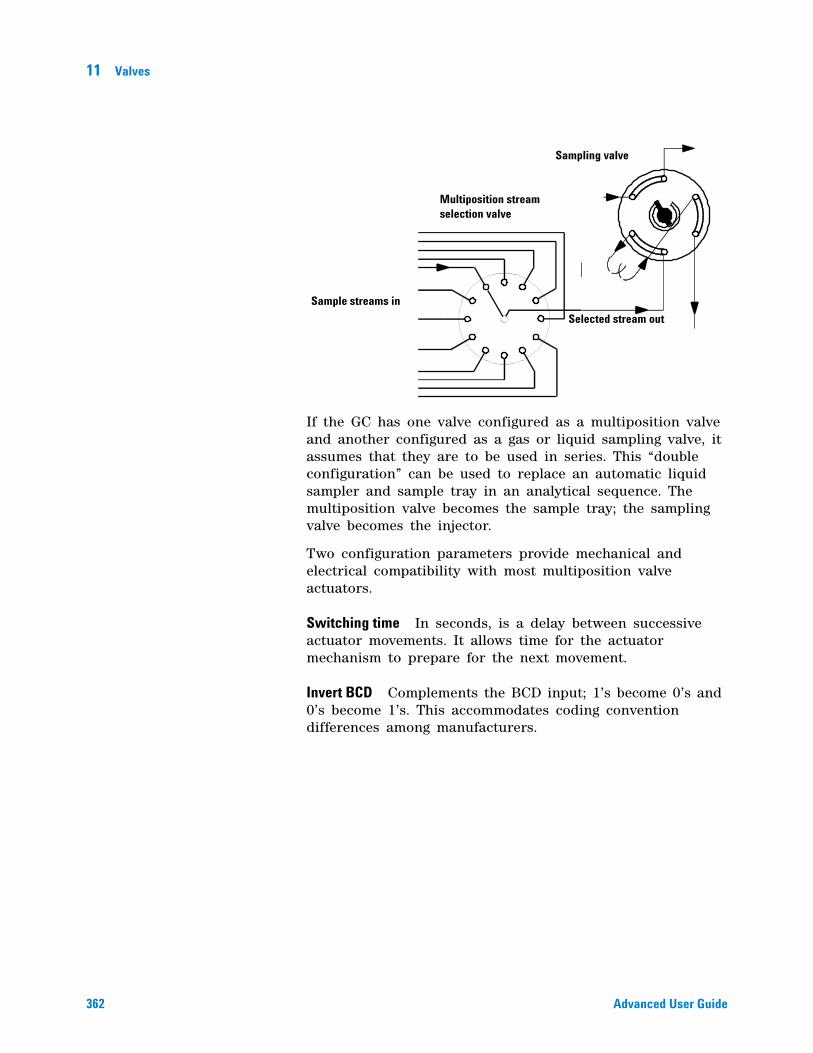
362 Advanced User Guide
11 Valves
If the GC has one valve configured as a multiposition valve and another configured as a gas or liquid sampling valve, it assumes that they are to be used in series. This “double configuration” can be used to replace an automatic liquid sampler and sample tray in an analytical sequence. The multiposition valve becomes the sample tray; the sampling valve becomes the injector.
Two configuration parameters provide mechanical and electrical compatibility with most multiposition valve actuators.
Switching time In seconds, is a delay between successive actuator movements. It allows time for the actuator mechanism to prepare for the next movement.
Invert BCD Complements the BCD input; 1’s become 0’s and 0’s become 1’s. This accommodates coding convention differences among manufacturers.
Sample streams in
Selected stream out
Multiposition stream selection valve
Sampling valve
363
Agilent 7890A Gas ChromatographAdvanced User Guide
Agilent Technologies
127683B Sampler
About the 7683B Sampler 364
Setting Parameters for the ALS 365
Solvent Saver 366
Sample tray setpoints 367
Storing setpoints 367
364 Advanced User Guide
12 7683B Sampler
About the 7683B Sampler
The 7683B Automatic Liquid Sampler (ALS) is controlled by a sequence that specifies what samples are to be analyzed, where the sample vials are located in the sampler tray (if used), what methods are to be used for each sample, and possibly what to do after the last sample to clean out the column. See “Creating Sequences” on page 121 for more information on sequences.
Hardware
Consult the 7683B for all mechanical details, such as installing/removing the tray, injectors, bar code reader, syringes, and so on. Follow the instructions for the 6890N GC.
Software
The new 7890A parameters are described in this chapter. Follow these instructions for all non- mechanical operations.
7683B Sampler 12
Advanced User Guide 365
Setting Parameters for the ALS
Pressing either of the injector keys allows you to edit injector control setpoints, such as injection volumes, sample and solvent washes, etc.
To edit the injector setpoints:
1 Press [Front Injector] or [Back Injector].
2 Scroll to the desired setpoint.
3 Enter a setpoint value, or turn the setpoint On or Off.
4 Press [Mode/Type] to make selections for syringe size and syringe plunger speed.
Injection volume Sample volume to be injected. Press [Mode/Type] to select. The available volumes depend on the syringe size configured.
• The selections represent 2%, 10%, 20%, 30%, 40%, and 50% of syringe size.
• Turn the injection volume Off to disable the injector.
Viscosity delay (0-7 seconds) How long the plunger pauses at the top of the pump and injection strokes. For viscous samples, the pause allows the sample to flow into the vacuum created in the syringe.
Inject Dispense Speed The speed of the syringe plunger during injection. Enables you to reduce the average speed of the plunger. Press [Mode/Type] to see the choices. The plunger speed during the pump and waste dispensing does not change.
Sample pumps (0-15) How many times the syringe plunger is moved up and down with the needle in the sample to expel air bubbles and improve reproducibility.
Sample washes (0-15) How many times the syringe is rinsed with sample before the injection. The wash volume is set by the Solvent Saver setting.
Solvent A post washes (0-15) How many times the syringe is washed with solvent A after injection.
Solvent A pre washes (0-15) How many times the syringe is washed with solvent A before the sample washes.
366 Advanced User Guide
12 7683B Sampler
Solvent B post washes (0-15) How many times the syringe is washed with solvent B after any solvent A washes.
Solvent B pre washes (0-15) How many times the syringe is washed with solvent B after any solvent A prewashes and before the sample washes.
Solvent B wash volume The percent of the syringe volume to be used for solvent B washes.
Sample Draw Speed Speed of the syringe plunger when drawing in sample.
Sample Disp Speed Speed of the syringe plunger when dispensing sample.
Solvent Draw Speed Speed of the syringe plunger when drawing in solvent.
Solvent Disp Speed Speed of the syringe plunger when dispensing solvent.
Pre dwell time (0-1) How long, in minutes, the needle remains in the inlet before the injection.
Post dwell time (0-1) How long, in minutes, the needle remains in the inlet after injection.
Sample offset (-2 to 30, Off) Sets variable sampling depth.
Injection Reps (1-99) How many times the injection and analysis should be repeated from each vial.
Injection Delay Time between multiple injections. Availability depends on the inlet type.
Solvent Saver
If you enter a non- zero value for any of the solvent or sample washes, the GC will ask for the wash volume. The default is 80% of the syringe volume. Press [Mode/Type] to see the other choices. This function allows you to conserve solvent during the washes.
7683B Sampler 12
Advanced User Guide 367
Sample tray setpoints
The sample tray delivers sample vials to the front and rear injectors according to the defined sequence parameters. There is a separate set of sequence parameters for each injector. The sample tray delivers vials to the front injector before the rear injector. Stored sequences and bar code configurations can be used to tell the sample tray where to deliver and retrieve sample vials.
Enable bar code Turns the bar code reader on or off.
1 Press [Sample tray] to access the sample tray and bar code reader setpoints.
2 Press [On] or [Off] to enable or disable the tray.
3 Press [On] or [Off] to enable or disable the bar code reader.
Storing setpoints
After setting up injector setpoints, sample tray setpoints and bar code reader configurations, store them as part of a method by following the procedures in To store a method from the keypad. This method becomes a part of the sequence used to run the samples.

368 Advanced User Guide
12 7683B Sampler
369
Agilent 7890A Gas ChromatographAdvanced User Guide
Agilent Technologies
13Cables
About Cables and Back Panel Connectors 370
Back panel connectors 370
Sampler connectors 370
The AUX connector 370
Signal connectors 371
REMOTE connector 371
EVENT connector 371
BCD input connector 371
RS-232 connector 371
LAN connector 371
Using the Remote Start/Stop cable 372
Cable Diagrams 377
Analog cable, general use 377
Remote start/stop cable 377
BCD cable 378
External event cable 379
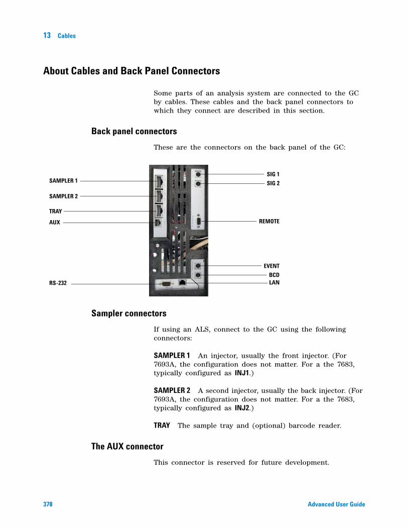
370 Advanced User Guide
13 Cables
About Cables and Back Panel Connectors
Some parts of an analysis system are connected to the GC by cables. These cables and the back panel connectors to which they connect are described in this section.
Back panel connectors
These are the connectors on the back panel of the GC:
Sampler connectors
If using an ALS, connect to the GC using the following connectors:
SAMPLER 1 An injector, usually the front injector. (For 7693A, the configuration does not matter. For a the 7683, typically configured as INJ1.)
SAMPLER 2 A second injector, usually the back injector. (For 7693A, the configuration does not matter. For a the 7683, typically configured as INJ2.)
TRAY The sample tray and (optional) barcode reader.
The AUX connector
This connector is reserved for future development.
RS-232 LAN
REMOTE
SAMPLER 1
SAMPLER 2
TRAY
AUX
SIG 1
SIG 2
EVENT
BCD
Cables 13
Advanced User Guide 371
Signal connectors
SIG1 and SIG2 are for the two analog output signals.
REMOTE connector
Provides a port to remotely start and stop other instruments. A maximum of 10 instruments can be synchronized using this connector. See “Using the Remote Start/Stop cable” on page 372 for more detail.
EVENT connector
This connector provides two passive contact closures and two 24- volt outputs for controlling external devices. The outputs are controlled by valve drivers 5 through 8.
BCD input connector
This connector provides two control relays and a BCD input for a stream selection valve.
RS-232 connector
This connector is reserved for future development.
LAN connector
Standard Local Area Network connector, for communication with data systems and other devices.
CAUTION This connector is similar to the EVENT connector. Plugging a non BCD cable into the BCD connector can damage the GC.
372 Advanced User Guide
13 Cables
Using the Remote Start/Stop cable
Remote start/stop is used to synchronize two or more instruments. For example, you might connect an integrator and the GC so that the [Start]/[Stop] buttons on either instrument control both of them. You can synchronize a maximum of ten instruments using Remote cables.
Connecting Agilent products
If connecting two Agilent products with Remote cables, the sending and receiving circuits will be compatible—just plug in both ends of the cable.
Connecting non-Agilent products
If connecting to a non- Agilent product, the following paragraphs contain information you will need to ensure compatibility.
APG Remote signal electrical specifications
The APG signals are a modified open collector type. The signal levels are generally TTL levels (low voltage is logic zero, high voltage is logic one) but the open circuit voltage will be between 2.5 and 3.7 Volts. The typical voltage is 3 Volts. A voltage over 2.2 volts will be interpreted as a high logic state while a voltage below 0.4 volts will be interpreted as a low logic state. These levels provide some margin over the specifications of the devices used.
The pull- up resistance, connected to the open- circuit voltage, is in the range of about 1K ohms to 1.5K ohms. For a logic- low state, for a single device on the bus, the minimum current you must be able to sink is 3.3 milliamps. Since devices are connected in parallel, when you have multiple devices this minimum current must be multiplied by the number of devices attached on the bus. The maximum voltage for a low- input state = 0.4V.
The bus is passively pulled high. Leakage current out of a port must be less than 0.2 milliamps to keep the voltage from being pulled lower than 2.2 volts. Higher leakage current may cause the state to be interpreted as a low.
Over- voltage protection - APG Remote connections are clamped by a zener diode to 5.6 Volts. Exceeding this voltage will damage the circuit (main board).
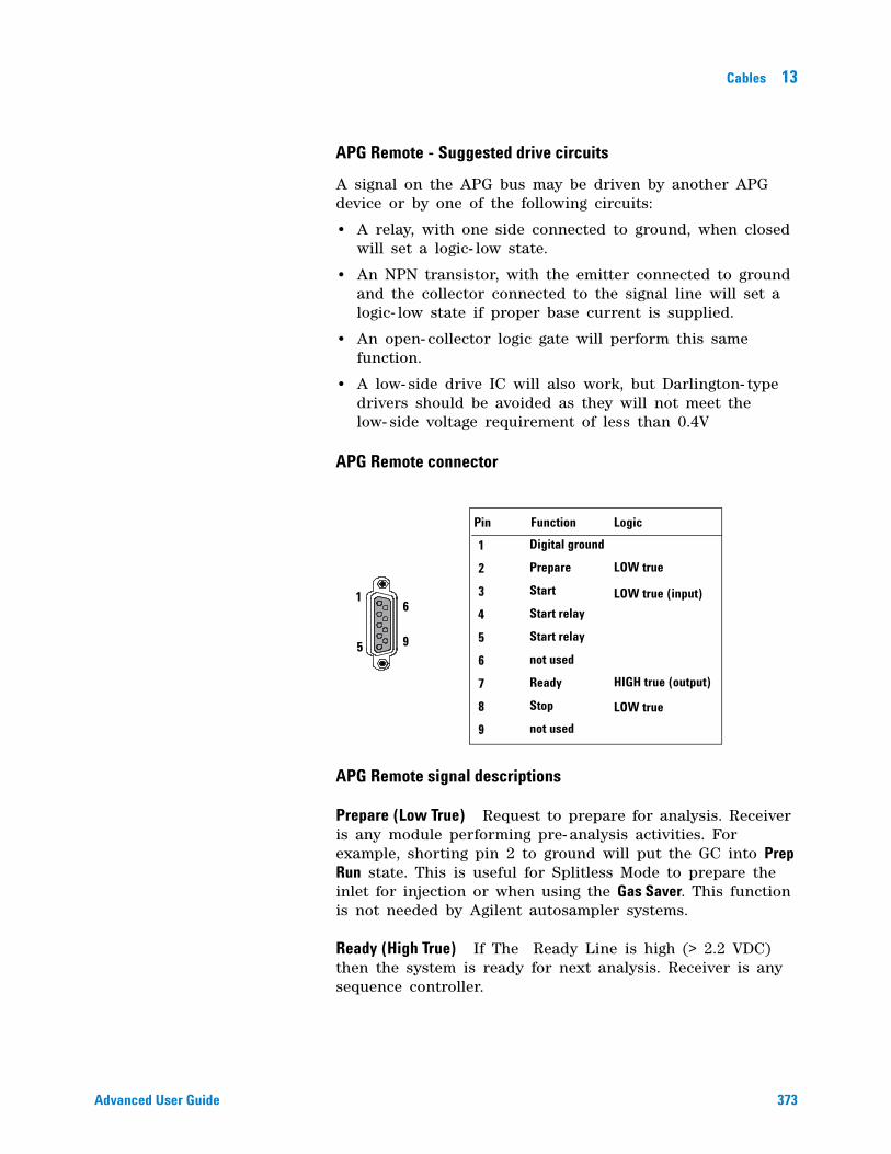
Cables 13
Advanced User Guide 373
APG Remote - Suggested drive circuits
A signal on the APG bus may be driven by another APG device or by one of the following circuits:
• A relay, with one side connected to ground, when closed will set a logic- low state.
• An NPN transistor, with the emitter connected to ground and the collector connected to the signal line will set a logic- low state if proper base current is supplied.
• An open- collector logic gate will perform this same function.
• A low- side drive IC will also work, but Darlington- type drivers should be avoided as they will not meet the low- side voltage requirement of less than 0.4V
APG Remote connector
APG Remote signal descriptions
Prepare (Low True) Request to prepare for analysis. Receiver is any module performing pre- analysis activities. For example, shorting pin 2 to ground will put the GC into Prep Run state. This is useful for Splitless Mode to prepare the inlet for injection or when using the Gas Saver. This function is not needed by Agilent autosampler systems.
Ready (High True) If The Ready Line is high (> 2.2 VDC) then the system is ready for next analysis. Receiver is any sequence controller.
1
5
6
9
Pin Function Logic
1
2
3
4
5
6
7
8
9
Digital ground
Prepare
Start
Start relay
Start relay
not used
Ready
Stop
not used
LOW true
LOW true (input)
HIGH true (output)
LOW true
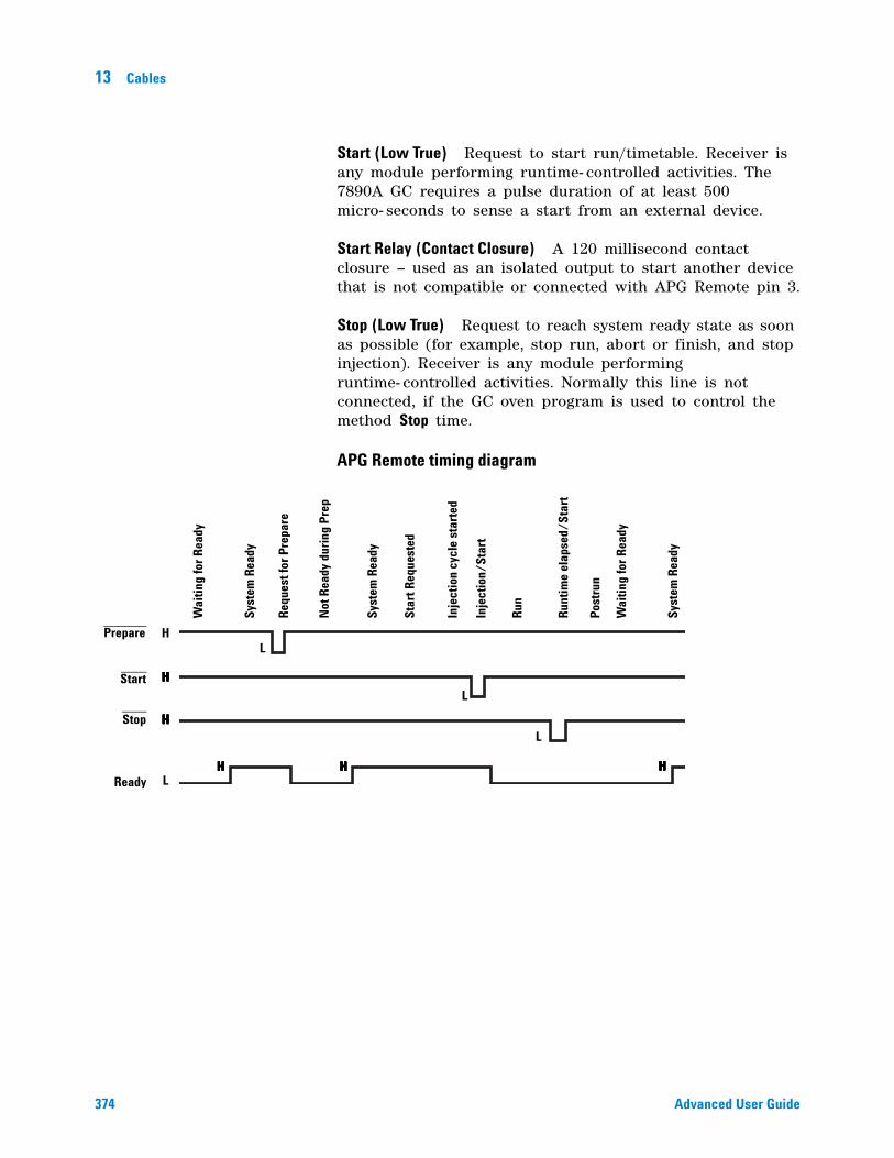
374 Advanced User Guide
13 Cables
Start (Low True) Request to start run/timetable. Receiver is any module performing runtime- controlled activities. The 7890A GC requires a pulse duration of at least 500 micro- seconds to sense a start from an external device.
Start Relay (Contact Closure) A 120 millisecond contact closure – used as an isolated output to start another device that is not compatible or connected with APG Remote pin 3.
Stop (Low True) Request to reach system ready state as soon as possible (for example, stop run, abort or finish, and stop injection). Receiver is any module performing runtime- controlled activities. Normally this line is not connected, if the GC oven program is used to control the method Stop time.
APG Remote timing diagram
Prepare
Start
Stop
Ready
H
H
HHHHHH
HHHHHHH
HHHHHHH HHHHHHHHHHHHHH
L
L
L
L
Wai
ting
for
Rea
dy
Syst
em R
eady
Req
uest
for
Prep
are
Not
Rea
dy d
urin
g Pr
ep
Syst
em R
eady
Star
t Req
uest
ed
Inje
ctio
n cy
cle
star
ted
Inje
ctio
n/St
art
Run
Run
time
elap
sed/
Star
t
Post
run
Wai
ting
for
Rea
dy
Syst
em R
eady
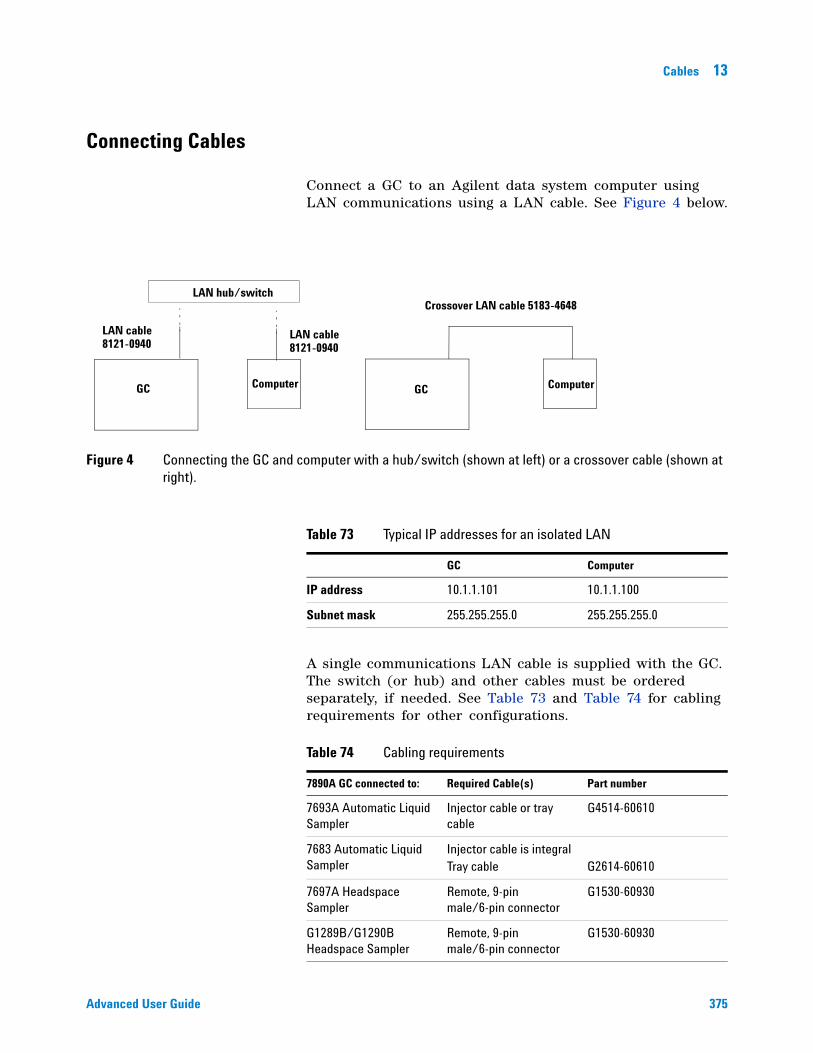
Cables 13
Advanced User Guide 375
Connecting Cables
Connect a GC to an Agilent data system computer using LAN communications using a LAN cable. See Figure 4 below.
A single communications LAN cable is supplied with the GC. The switch (or hub) and other cables must be ordered separately, if needed. See Table 73 and Table 74 for cabling requirements for other configurations.
Figure 4 Connecting the GC and computer with a hub/switch (shown at left) or a crossover cable (shown at right).
LAN cableLAN cable
ComputerGC
LAN hub/switch
ComputerGC
Crossover LAN cable 5183-4648
8121-0940 8121-0940
Table 73 Typical IP addresses for an isolated LAN
GC Computer
IP address 10.1.1.101 10.1.1.100
Subnet mask 255.255.255.0 255.255.255.0
Table 74 Cabling requirements
7890A GC connected to: Required Cable(s) Part number
7693A Automatic Liquid Sampler
Injector cable or tray cable
G4514-60610
7683 Automatic Liquid Sampler
Injector cable is integral Tray cable G2614-60610
7697A Headspace Sampler
Remote, 9-pin male/6-pin connector
G1530-60930
G1289B/G1290B Headspace Sampler
Remote, 9-pin male/6-pin connector
G1530-60930
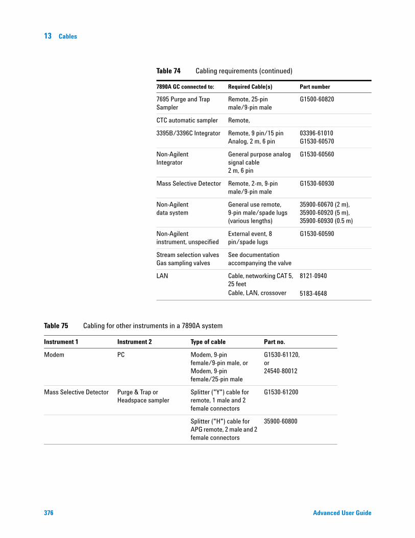
376 Advanced User Guide
13 Cables
7695 Purge and Trap Sampler
Remote, 25-pin male/9-pin male
G1500-60820
CTC automatic sampler Remote,
3395B/3396C Integrator Remote, 9 pin/15 pin Analog, 2 m, 6 pin
03396-61010 G1530-60570
Non-Agilent Integrator
General purpose analog signal cable 2 m, 6 pin
G1530-60560
Mass Selective Detector Remote, 2-m, 9-pin male/9-pin male
G1530-60930
Non-Agilent data system
General use remote, 9-pin male/spade lugs (various lengths)
35900-60670 (2 m), 35900-60920 (5 m), 35900-60930 (0.5 m)
Non-Agilent instrument, unspecified
External event, 8 pin/spade lugs
G1530-60590
Stream selection valves Gas sampling valves
See documentation accompanying the valve
LAN Cable, networking CAT 5, 25 feetCable, LAN, crossover
8121-0940
5183-4648
Table 74 Cabling requirements (continued)
7890A GC connected to: Required Cable(s) Part number
Table 75 Cabling for other instruments in a 7890A system
Instrument 1 Instrument 2 Type of cable Part no.
Modem PC Modem, 9-pin female/9-pin male, or Modem, 9-pin female/25-pin male
G1530-61120, or 24540-80012
Mass Selective Detector Purge & Trap or Headspace sampler
Splitter ("Y") cable for remote, 1 male and 2 female connectors
G1530-61200
Splitter ("H") cable for APG remote, 2 male and 2 female connectors
35900-60800
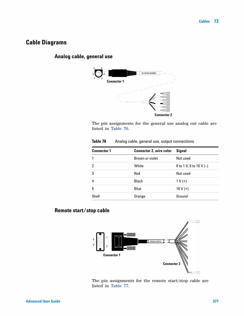
Cables 13
Advanced User Guide 377
Cable Diagrams
Analog cable, general use
The pin assignments for the general use analog out cable are listed in Table 76.
Remote start/stop cable
The pin assignments for the remote start/stop cable are listed in Table 77.
Table 76 Analog cable, general use, output connections
Connector 1 Connector 2, wire color Signal
1 Brown or violet Not used
2 White 0 to 1 V, 0 to 10 V (–)
3 Red Not used
4 Black 1 V (+)
6 Blue 10 V (+)
Shell Orange Ground
Connector 1
Connector 2
Connector 1
Connector 2
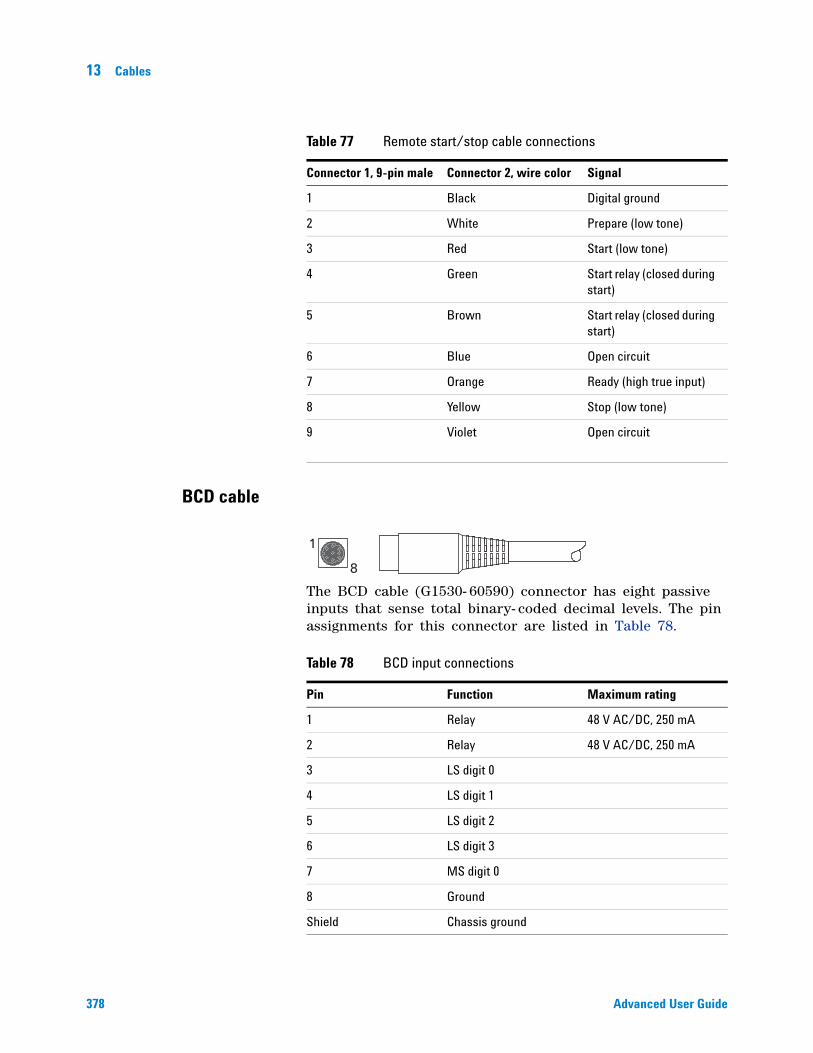
378 Advanced User Guide
13 Cables
BCD cable
The BCD cable (G1530- 60590) connector has eight passive inputs that sense total binary- coded decimal levels. The pin assignments for this connector are listed in Table 78.
Table 77 Remote start/stop cable connections
Connector 1, 9-pin male Connector 2, wire color Signal
1 Black Digital ground
2 White Prepare (low tone)
3 Red Start (low tone)
4 Green Start relay (closed during start)
5 Brown Start relay (closed during start)
6 Blue Open circuit
7 Orange Ready (high true input)
8 Yellow Stop (low tone)
9 Violet Open circuit
Table 78 BCD input connections
Pin Function Maximum rating
1 Relay 48 V AC/DC, 250 mA
2 Relay 48 V AC/DC, 250 mA
3 LS digit 0
4 LS digit 1
5 LS digit 2
6 LS digit 3
7 MS digit 0
8 Ground
Shield Chassis ground
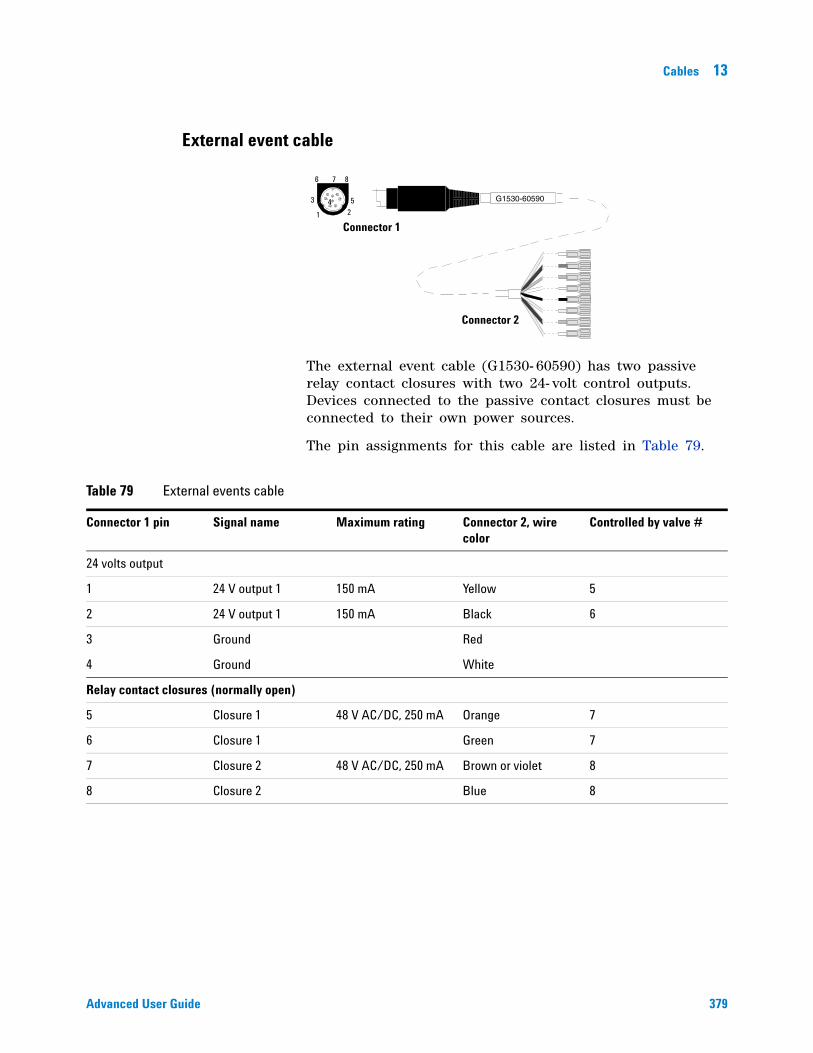
Cables 13
Advanced User Guide 379
External event cable
The external event cable (G1530- 60590) has two passive relay contact closures with two 24- volt control outputs. Devices connected to the passive contact closures must be connected to their own power sources.
The pin assignments for this cable are listed in Table 79.
1 2
3 4 5
6 7 8
Connector 1
Connector 2
Table 79 External events cable
Connector 1 pin Signal name Maximum rating Connector 2, wire color
Controlled by valve #
24 volts output
1 24 V output 1 150 mA Yellow 5
2 24 V output 1 150 mA Black 6
3 Ground Red
4 Ground White
Relay contact closures (normally open)
5 Closure 1 48 V AC/DC, 250 mA Orange 7
6 Closure 1 Green 7
7 Closure 2 48 V AC/DC, 250 mA Brown or violet 8
8 Closure 2 Blue 8

380 Advanced User Guide
13 Cables
381
Agilent 7890A Gas ChromatographAdvanced User Guide
Agilent Technologies
14GC Output Signals
About Signals 382
Signal Types 383
Value 383
Analog Signals 385
Analog zero 385
Analog range 385
Analog data rates 386
Selecting fast peaks (analog output) 387
Digital Signals 388
Digital zero 388
Signal Freeze and Resume 388
Data rates with Agilent data systems 389
Column Compensation 392
Creating a column compensation profile 393
Making a run using analog output column compensation 393
Plotting a stored column compensation profile 394
Test Plot 395
382 Advanced User Guide
14 GC Output Signals
About Signals
Signal is the GC output to a data handling device, analog or digital. It can be a detector output or the output from flow, temperature, or pressure sensors. Two signal output channels are provided.
Signal output can be either analog or digital, depending on your data handling device. Analog output is available at either of two speeds, suitable to peaks with minimum widths of 0.004 minutes (fast data rate) or 0.01 minutes (normal rate). Analog output ranges are 0 to 1 V, 0 to 10 V, and 0 to 1 mV.
Digital output rates are set by your Agilent data system, such as ChemStation or EZChrom.
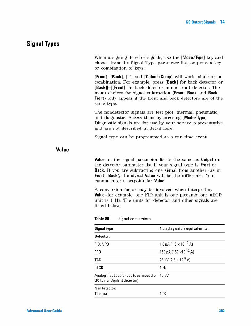
GC Output Signals 14
Advanced User Guide 383
Signal Types
When assigning detector signals, use the [Mode/Type] key and choose from the Signal Type parameter list, or press a key or combination of keys.
[Front], [Back], [–], and [Column Comp] will work, alone or in combination. For example, press [Back] for back detector or [Back][–][Front] for back detector minus front detector. The menu choices for signal subtraction (Front - Back and Back - Front) only appear if the front and back detectors are of the same type.
The nondetector signals are test plot, thermal, pneumatic, and diagnostic. Access them by pressing [Mode/Type]. Diagnostic signals are for use by your service representative and are not described in detail here.
Signal type can be programmed as a run time event.
Value
Value on the signal parameter list is the same as Output on the detector parameter list if your signal type is Front or Back. If you are subtracting one signal from another (as in Front – Back), the signal Value will be the difference. You cannot enter a setpoint for Value.
A conversion factor may be involved when interpreting Value—for example, one FID unit is one picoamp; one uECD unit is 1 Hz. The units for detector and other signals are listed below.
Table 80 Signal conversions
Signal type 1 display unit is equivalent to:
Detector:
FID, NPD 1.0 pA (1.0 × 10⁻¹² A)
FPD 150 pA (150 ×10-12 A)
TCD 25 uV (2.5 × 10⁻⁵ V)
µECD 1 Hz
Analog input board (use to connect the GC to non-Agilent detector)
15 µV
Nondetector:Thermal 1 °C
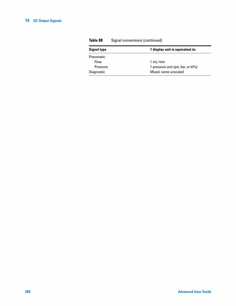
384 Advanced User Guide
14 GC Output Signals
Pneumatic:FlowPressure
Diagnostic
1 mL/min1 pressure unit (psi, bar, or kPa)Mixed, some unscaled
Table 80 Signal conversions (continued)
Signal type 1 display unit is equivalent to:
GC Output Signals 14
Advanced User Guide 385
Analog Signals
If you use an analog recorder, you may need to adjust the signal to make it more usable. Zero and Range in the Signal parameter list do this.
Analog zero
Zero Subtracts value entered from baseline. Press [On/Yes] to set to current Value or [Off/No] to cancel.
This is used to correct baseline elevation or offsets. A common application is to correct a baseline shift that occurs as the result of a valve operation. After zeroing, the analog output signal is equal to the Value line of the parameter list minus the Zero setpoint.
Zero can be programmed as a run time event. For details, see “Run Time Programming” on page 16.
1 Verify that the detector is on and in a ready state.
2 Press [Analog Out 1] or [Analog Out 2].
3 Scroll to Zero.
4 Press [On/Yes] to set Zero at the current signal value, or Enter a number between - 500000 and +500000. A value smaller than the current Zero shifts baseline up.
Analog range
Range Scales data coming from the detector
Range is also referred to as gain, scaling, or sizing. It sizes the data coming from the detector to the analog signal circuits to avoid overloading the circuits (clamping). Range scales all analog signals.
If a chromatogram looks like A or B in the next figure, the data needs to be scaled (as in C) so that all peaks are visible on the paper.
Valid setpoints are from 0 to 13 and represent 20 (=1) to 213 (=8192). Changing a setpoint by 1 changes the height of the chromatogram by a factor of 2. The following chromatograms illustrate this. Use the smallest possible value to minimize integration error.
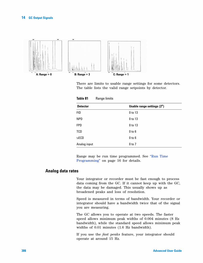
386 Advanced User Guide
14 GC Output Signals
There are limits to usable range settings for some detectors. The table lists the valid range setpoints by detector.
Range may be run time programmed. See “Run Time Programming” on page 16 for details.
Analog data rates
Your integrator or recorder must be fast enough to process data coming from the GC. If it cannot keep up with the GC, the data may be damaged. This usually shows up as broadened peaks and loss of resolution.
Speed is measured in terms of bandwidth. Your recorder or integrator should have a bandwidth twice that of the signal you are measuring.
The GC allows you to operate at two speeds. The faster speed allows minimum peak widths of 0.004 minutes (8 Hz bandwidth), while the standard speed allows minimum peak widths of 0.01 minutes (1.6 Hz bandwidth).
If you use the fast peaks feature, your integrator should operate at around 15 Hz.
C: Range = 1B: Range = 3A: Range = 0
Table 81 Range limits
Detector Usable range settings (2x)
FID 0 to 13
NPD 0 to 13
FPD 0 to 13
TCD 0 to 6
υECD 0 to 6
Analog input 0 to 7
GC Output Signals 14
Advanced User Guide 387
Selecting fast peaks (analog output)
1 Press [Config][Analog 1] or [Config][Analog 2].
2 Scroll to Fast peaks and press [On].
Agilent does not recommend using Fast peaks with a thermal conductivity detector. Since the gas streams switch at 5 Hz, the gain in peak width is offset by increased noise.
388 Advanced User Guide
14 GC Output Signals
Digital Signals
The GC outputs digital signals only to an Agilent data system. The following discussions describe features that impact the data sent to data systems, not the analog data available to integrators. Access these features from the data system. These features are not accessible from the GC keypad.
Digital zero
Available only from an Agilent data system.
Digital signal outputs respond to a zero command by subtracting the signal level at the time of the command from all future values.
Signal Freeze and Resume
Available only from an Agilent data system.
Some run time operations, such as changing signal assignments or switching a valve, can cause baseline upsets. Other factors can cause baseline upsets also. The GC can compensate for this by pausing (freezing) the signal at a particular value, using that signal value for a specified duration, and then resuming normal signal output.
Consider a system that uses a switching valve. When the valve switches, an anomaly occurs in the baseline. By freezing and resuming the signal, the anomaly can be removed so that the peak identification and integration software operates more smoothly.
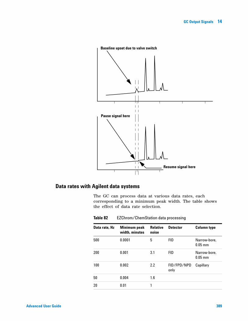
GC Output Signals 14
Advanced User Guide 389
Data rates with Agilent data systems
The GC can process data at various data rates, each corresponding to a minimum peak width. The table shows the effect of data rate selection.
Baseline upset due to valve switch
Pause signal here
Resume signal here
Table 82 EZChrom/ChemStation data processing
Data rate, Hz Minimum peak width, minutes
Relative noise
Detector Column type
500 0.0001 5 FID Narrow-bore, 0.05 mm
200 0.001 3.1 FID Narrow-bore, 0.05 mm
100 0.002 2.2 FID/FPD/NPD only
Capillary
50 0.004 1.6
20 0.01 1
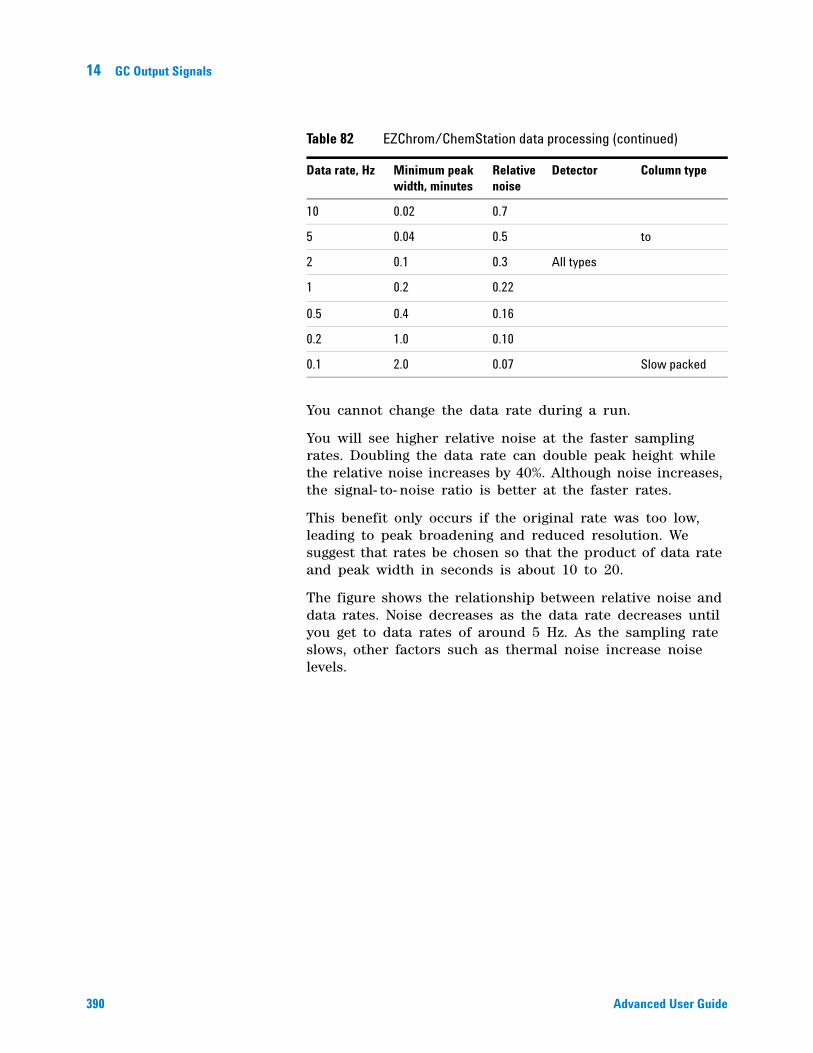
390 Advanced User Guide
14 GC Output Signals
You cannot change the data rate during a run.
You will see higher relative noise at the faster sampling rates. Doubling the data rate can double peak height while the relative noise increases by 40%. Although noise increases, the signal- to- noise ratio is better at the faster rates.
This benefit only occurs if the original rate was too low, leading to peak broadening and reduced resolution. We suggest that rates be chosen so that the product of data rate and peak width in seconds is about 10 to 20.
The figure shows the relationship between relative noise and data rates. Noise decreases as the data rate decreases until you get to data rates of around 5 Hz. As the sampling rate slows, other factors such as thermal noise increase noise levels.
10 0.02 0.7
5 0.04 0.5 to
2 0.1 0.3 All types
1 0.2 0.22
0.5 0.4 0.16
0.2 1.0 0.10
0.1 2.0 0.07 Slow packed
Table 82 EZChrom/ChemStation data processing (continued)
Data rate, Hz Minimum peak width, minutes
Relative noise
Detector Column type
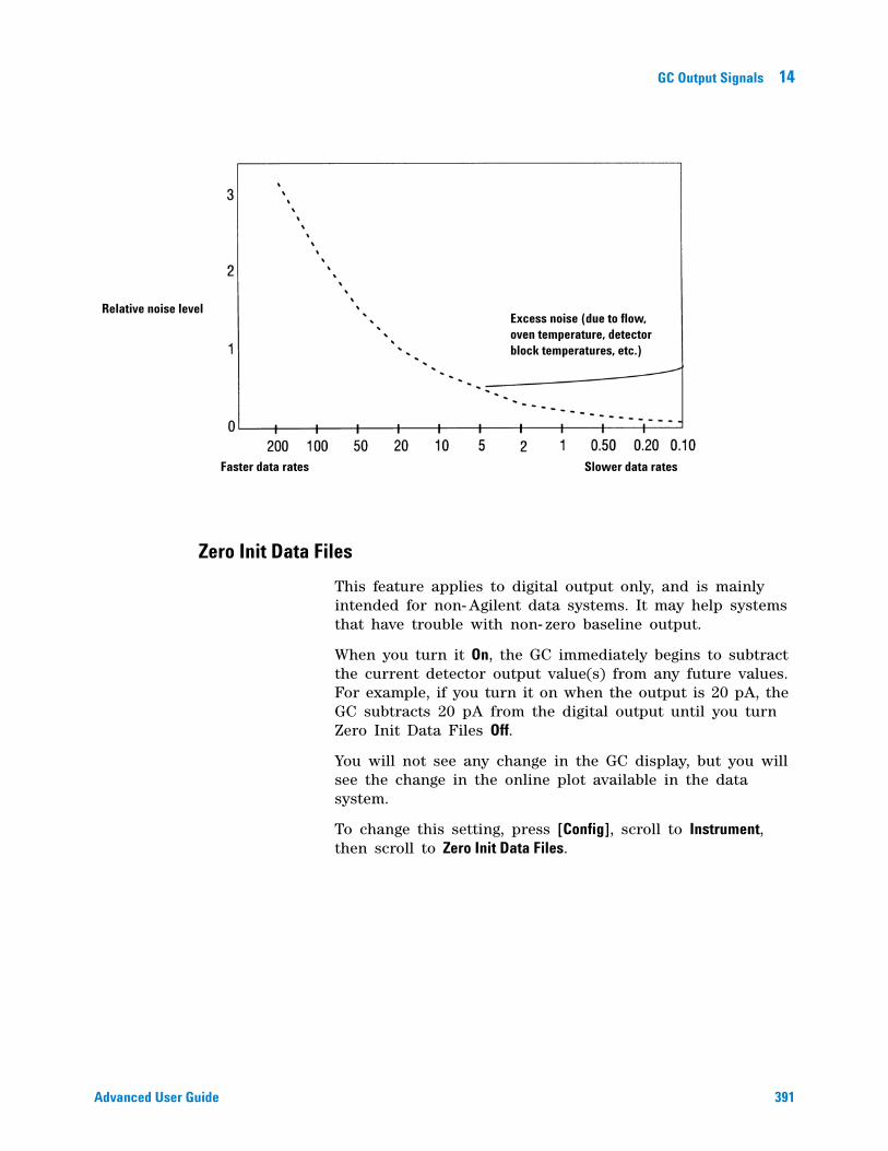
GC Output Signals 14
Advanced User Guide 391
Zero Init Data Files
This feature applies to digital output only, and is mainly intended for non- Agilent data systems. It may help systems that have trouble with non- zero baseline output.
When you turn it On, the GC immediately begins to subtract the current detector output value(s) from any future values. For example, if you turn it on when the output is 20 pA, the GC subtracts 20 pA from the digital output until you turn Zero Init Data Files Off.
You will not see any change in the GC display, but you will see the change in the online plot available in the data system.
To change this setting, press [Config], scroll to Instrument, then scroll to Zero Init Data Files.
Relative noise level
Slower data ratesFaster data rates
Excess noise (due to flow, oven temperature, detector block temperatures, etc.)
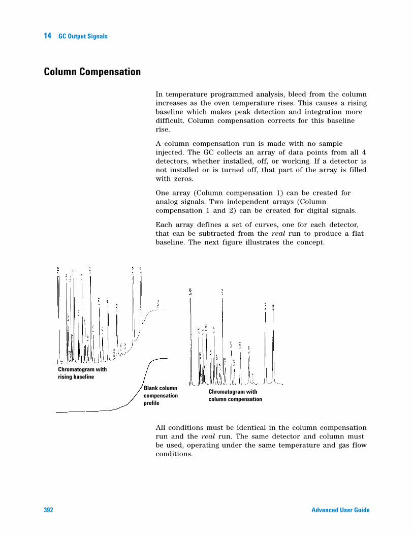
392 Advanced User Guide
14 GC Output Signals
Column Compensation
In temperature programmed analysis, bleed from the column increases as the oven temperature rises. This causes a rising baseline which makes peak detection and integration more difficult. Column compensation corrects for this baseline rise.
A column compensation run is made with no sample injected. The GC collects an array of data points from all 4 detectors, whether installed, off, or working. If a detector is not installed or is turned off, that part of the array is filled with zeros.
One array (Column compensation 1) can be created for analog signals. Two independent arrays (Column compensation 1 and 2) can be created for digital signals.
Each array defines a set of curves, one for each detector, that can be subtracted from the real run to produce a flat baseline. The next figure illustrates the concept.
All conditions must be identical in the column compensation run and the real run. The same detector and column must be used, operating under the same temperature and gas flow conditions.
Chromatogram with rising baseline
Chromatogram with column compensation
Blank column compensation profile
GC Output Signals 14
Advanced User Guide 393
Creating a column compensation profile
1 Set up the instrument for a run.
2 Make a blank run to verify that the baseline is clean. This is particularly important for new conditions or if the GC has been idle for several hours.
3 Press [Column Comp].
4 Select Col comp 1 or Col comp 2 (these are the two arrays).
5 Select Start compensation run and press [Enter].
6 If the run is successful, the first line of the parameter list will say Data ok, and a time and date will appear at the bottom.
Making a run using analog output column compensation
1 Set the chromatographic conditions. They must be identical to those in the stored column compensation run except that Final time in the last ramp of the oven program can be longer or shorter.
2 Press [Analog Out 1] or [Analog Out 2].
3 Scroll to Type and press [Mode/Type].
4 The choices for an analog signal are:
Front detector Back detector Front - column comp 1 Front column compensation 1 Back column compensation 1 Aux 1 column compensation 1 Aux 2 column compensation 1 Test plot
5 Choose an option from the list.
6 Enter setpoints for Zero and Range, if applicable.
7 Start your run.
Making a run using digital output column compensation
1 Set each detector output separately.
2 Press [Config][Detector name]. Scroll to Signal and press [Mode/Type]. Select from:
No Column Compensation Detector - ColComp 1 Detector - ColComp 2
394 Advanced User Guide
14 GC Output Signals
This changes the digital output. You cannot get both compensated and uncompensated digital data from the same detector at the same time. However, it does not affect the analog output.
Plotting a stored column compensation profile
1 Press [Analog Out 1] or [Analog Out 2].
2 Scroll to Type: and press [Mode/Type].
3 Select the profile to be plotted.
4 Press [Start].
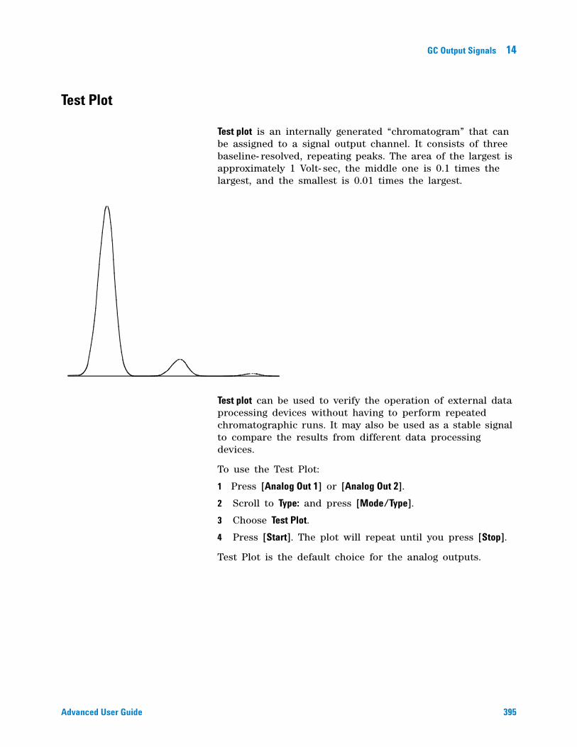
GC Output Signals 14
Advanced User Guide 395
Test Plot
Test plot is an internally generated “chromatogram” that can be assigned to a signal output channel. It consists of three baseline- resolved, repeating peaks. The area of the largest is approximately 1 Volt- sec, the middle one is 0.1 times the largest, and the smallest is 0.01 times the largest.
Test plot can be used to verify the operation of external data processing devices without having to perform repeated chromatographic runs. It may also be used as a stable signal to compare the results from different data processing devices.
To use the Test Plot:
1 Press [Analog Out 1] or [Analog Out 2].
2 Scroll to Type: and press [Mode/Type].
3 Choose Test Plot.
4 Press [Start]. The plot will repeat until you press [Stop].
Test Plot is the default choice for the analog outputs.

396 Advanced User Guide
14 GC Output Signals

397
Agilent 7890A Gas ChromatographAdvanced User Guide
Agilent Technologies
15Miscellaneous Topics
Auxiliary Devices 398
About Auxiliary Pressure Control 398
About Aux Thermal Zone Control 399
About Cryo Trap Control 399
About Auxiliary Device Contacts 400
About the 24V Auxiliary Device Power Supply 400
About Auxiliary Columns 400
About Auxiliary Detectors 401
To Use the Stopwatch 402
Service Mode 403
Service Reminders 403
Other functions 405
398 Advanced User Guide
15 Miscellaneous Topics
Auxiliary Devices
About Auxiliary Pressure Control
Pressure units
There are two common ways of expressing gas pressures:
psia Absolute pressure, measured relative to vacuum.
psig Gauge pressure, measured relative to atmospheric pressure. This name is used because most pressure gauges have one side of the sensing element exposed to the atmosphere.
The two measurements are related by:
psia = psig + atmospheric pressure
Two-channel pressure control module (PCM)
The PCM has two different channels. Channel 1 may be either flow or pressure controlled and may be flow/pressure programmed. It is essentially identical to the packed column inlet flow module (see “About the Multimode Inlet).
Channel 2 is pressure only, but may be used in either a forward- or back- pressure mode by changing connections.
Both channels are controlled by the same parameter list. The first two lines are for channel 1; the remaining lines are for channel 2.
The forward- pressure mode requires the user to supply a downstream flow resistance, possibly a frit.
The back- pressure mode is most useful with gas sampling valves. By connecting the sample exit line from the valve to the vent fitting of the PCM, pressure in the sample loop can be controlled.
Three-channel auxiliary pressure controller (Aux PCM)
All channels are 3- ramp programmable. Up to three modules may be installed, for a total of 9 pressure- regulated channels.
Miscellaneous Topics 15
Advanced User Guide 399
Setting parameters for auxiliary pressure control
1 Press [Aux EPC #] and scroll to the channel you wish to control. Press [Enter].
2 Scroll to Initial pressure. Enter a value and press [Enter].
3 If desired, enter a pressure program using the time and rate functions.
4 Press [On/Yes] to apply Initial pressure and start the program.
About Aux Thermal Zone Control
There can be up to 3 aux thermal controlled zones.
These zones are 3- ramp programmable.
Run time events may be used to schedule specific temperatures during the run.
Setting parameters for the aux thermal zone control
1 Press [Aux Temp #] and scroll to the zone you wish to control. Press [Enter].
2 Scroll to Temperature. Enter a value and press [Enter].
3 Scroll to Initial time. Enter a value and press [Enter].
4 Scroll to Rate 1. Enter 0 to end the program here or a positive value to create a temperature program.
About Cryo Trap Control
When configured as a cryo trap, an aux thermal zone has the following parameters:
Temperature Displays the current trap temperature and setpoint. Press [On/Off] to turn the zone on or off.
• If On, the cryo trap temperature will remain 10 °C above the current oven temperature, following the oven program.
• If Off, the GC does not control the trap temperature.
Cold Trap Temperature Enter the target temperature for cryo trap operation and press [Enter]. Enable this temperature using run time On and Off events for the aux thermal zone.
400 Advanced User Guide
15 Miscellaneous Topics
To use the cryo trap during a run:
1 Press [Aux Temp #] and scroll to the zone you wish to control. Press [Enter].
2 Scroll to Temperature. Press [On/Off] to turn the zone on or off, as desired (typically, On).
3 Scroll to Cold Trap Temperature. Enter a value and press [Enter].
4 Press [Run Table].
5 Press [Mode/Type].
6 Scroll to Cryo trap. Press [Enter] to add a cryo trap event to the run table.
7 Enter a value for the Time: and press [Enter]. Scroll to Cryo trap cooling and press [On/Yes] to turn it on.
This event sets the cryo trap temperature to the Cold Trap Temperature setpoint. The trap remains at this temperature until another event turns it off, or until the run ends.
8 Enter another Cryo Trap event to turn the trap temperature Off at the desired run time.
This event sets the cryo trap to track the oven temperature + 10 °C for the remainder of the run.
About Auxiliary Device Contacts
These contacts are controlled by the external valve drivers. See “The external valve drivers” on page 356.
About the 24V Auxiliary Device Power Supply
This is controlled by the external valve drivers. See “The external valve drivers” on page 356.
About Auxiliary Columns
Defines up to 6 columns (includes Col 1 and Col 2).
1 Press [Config][Aux Col #] and enter a column number. Press [Enter].
2 Define/configure the column. See “Column #” on page 34 for details.
Miscellaneous Topics 15
Advanced User Guide 401
About Auxiliary Detectors
The GC supports up to two auxiliary detectors in addition to the Front and Back detectors that mount on the top of the oven.
Aux Det # 1 This can only be a TCD, and mounts in a carrier on the left side of the oven together with its flow module.
Aux Det # 2 This can only be an analog input board (AIB). It is used to receive and process data from a non- Agilent detector or other source.
402 Advanced User Guide
15 Miscellaneous Topics
To Use the Stopwatch
In the stopwatch mode, both the time (to 0.1 second) and reciprocal time (to 0.01 min-1) are displayed. The stopwatch is useful when measuring flows with a bubble flowmeter.
1 Press [Time] and scroll to the time = line.
2 Press [Enter] to start the stopwatch.
3 Press [Enter] again to stop.
4 Press [Clear] to set to zero.
You can access other functions while the stopwatch is running. Press [Time] again to view the stopwatch display.
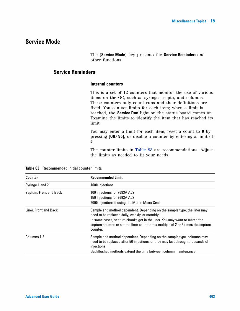
Miscellaneous Topics 15
Advanced User Guide 403
Service Mode
The [Service Mode] key presents the Service Reminders and other functions.
Service Reminders
Internal counters
This is a set of 12 counters that monitor the use of various items on the GC, such as syringes, septa, and columns. These counters only count runs and their definitions are fixed. You can set limits for each item; when a limit is reached, the Service Due light on the status board comes on. Examine the limits to identify the item that has reached its limit.
You may enter a limit for each item, reset a count to 0 by pressing [Off/No], or disable a counter by entering a limit of 0.
The counter limits in Table 83 are recommendations. Adjust the limits as needed to fit your needs.
Table 83 Recommended initial counter limits
Counter Recommended Limit
Syringe 1 and 2 1000 injections
Septum, Front and Back 100 injections for 7683A ALS150 injections for 7693A ALS2000 injections if using the Merlin Micro Seal
Liner, Front and Back Sample and method dependent. Depending on the sample type, the liner may need to be replaced daily, weekly, or monthly. In some cases, septum chunks get in the liner. You may want to match the septum counter, or set the liner counter to a multiple of 2 or 3 times the septum counter.
Columns 1-6 Sample and method dependent. Depending on the sample type, columns may need to be replaced after 50 injections, or they may last through thousands of injections.Backflushed methods extend the time between column maintenance.
404 Advanced User Guide
15 Miscellaneous Topics
Advanced counters
The GC provides storage for 64 advanced counters. They each have two thresholds, and the actions based on these counters can be: do nothing, turn on the Service Due light, or light the Service Due light and go Not ready.
Advanced counters are not accessible through the GC keyboard, except for the Disable Advanced Counters function of the Service Reminders. If they are not disabled, they continue to count, and continue to act on the set thresholds. This could cause the GC to become Not ready.
Since the advanced counters cannot be reset or manipulated without the Agilent Instrument Utilities software, Disable Advanced Counters is provided so that they can be turned off from the GC keyboard by someone who does not wish to use them, the Instrument Utilities software, or an Agilent data system. These users should disable the advanced counters from the keypad to avoid possible problems.
Counters can be individually enabled (count or don’t count), individually reset (start over), and individually set as counting elapsed seconds or runs. They can be assigned arbitrary “meanings”, allowing you to set up counters for equipment of your choice.
Each counter has an ID that can be associated with a concept, such as front inlet gold seal, and can count the number of elapsed runs or seconds since the last reset, from which one can infer the gold- seal’s in- service time or count.
A ChemStation can enable or disable individual counters in association with a method, so that only the counters for things used by the method advance.
To set up advanced counters
1 Use the Agilent data system to set the counters that increment with each injection cycle. Do this for each method used.
2 In the Agilent Instrument Utilities software, set up limits for each counter enabled in the previous step.
3 On the GC front panel, enable advanced counters.
Press the [Service Mode] key, then scroll. If the display shows an entry Enable Advanced Counters, select it and press [On/Yes].

Miscellaneous Topics 15
Advanced User Guide 405
Other functions
These are for use by trained Agilent personnel. They are described in the Service Manual.

406 Advanced User Guide
15 Miscellaneous Topics