Manual de Prog Gem-p1664 Con Rp1ca
56
HARDWIRE WIRELESS GEM-P1664EX CONTROL PANEL/COMMUNICATOR Programming the GEM-P1664EX Control Panel with the "Classic" GEM-RP1CAe2 Keypad and the "K Series" GEM-K1CA Keypad WI1386 5/05 © NAPCO 2005 Quick Start (for "Classic" GEM-RP1CAe2) 1. Refer to the wiring diagram, connect Siren, Aux. Power, PGM Output, Remote Bus, Earth ground, Zone and Tele- phone wiring. NOTE: See Installation Instructions (WI1388). 2. Connect AC power first and then the battery. 3. Configure the keypad (see page 42). 4. Access the Easy Menu Driven (Dealer Program) Mode: Press 456789 A Press NO (g) until “ACTIVATE PROGRAM Y/N” appears on the keypad display. Press YES (F) to Enter Dealer Program Mode. Go to page 5. Dealer Code Quick Start (for "K-Series" GEM-K1CA) 1. Refer to the wiring diagram, connect Siren, Aux. Power, PGM Output, Remote Bus, Earth ground, Zone and Tele- phone wiring. NOTE: See Installation Instructions (WI1388). 2. Connect AC power first and then the battery. 3. Configure the keypad (see page 42). 4. Access the Easy Menu Driven (Dealer Program) Mode: Press 456789 R Press NO (Q) until “ACTIVATE PROGRAM Y/N” appears on the keypad display. Press YES (P) to Enter Dealer Program Mode. Go to page 5. Dealer Code "K Series" GEM-K1CA GEMINI SYSTEM READY 01/01/05 12:00 AM ARMED COMPUTERIZED SECURITY SYSTEM STATUS R 1 2 3 B 4 5 6 C 7 8 9 0 U NEXT/YES P PRIOR/NO Q AREA G PROGRAMMING INSTRUCTIONS R "Classic" GEM-RP1CAe2 GEMINI SYSTEM READY 01/01/05 12:00 AM ARMED COMPUTERIZED SECURITY SYSTEM STATUS A 1 2 3 B 4 5 6 C 7 8 9 0 D NEXT/YES E PRIOR/NO F AREA G Publicly traded on NASDAQ Symbol: NSSC
-
Upload
anamaria-theodora-stanescu -
Category
Documents
-
view
69 -
download
8
description
Manual de instalare sistem de alarma
Transcript of Manual de Prog Gem-p1664 Con Rp1ca

HARDWIRE WIRELESS
G E M - P 1 6 6 4 E X CONTROL PANEL/COMMUNICATOR
Programming the GEM-P1664EX Control Panel with the "Classic" GEM-RP1CAe2 Keypad and the "K Series" GEM-K1CA Keypad
WI1386 5/05 © NAPCO 2005
Quick Start (for "Classic" GEM-RP1CAe2)
1. Refer to the wiring diagram, connect Siren, Aux. Power, PGM Output, Remote Bus, Earth ground, Zone and Tele-phone wiring. NOTE: See Installation Instructions (WI1388).
2. Connect AC power first and then the battery.
3. Configure the keypad (see page 42).
4. Access the Easy Menu Driven (Dealer Program) Mode:
Press 456789 A
Press NO (g) until “ACTIVATE PROGRAM Y/N” appears on the keypad display.
Press YES (F) to Enter Dealer Program Mode. Go to page 5.
Dealer Code
Quick Start (for "K-Series" GEM-K1CA)
1. Refer to the wiring diagram, connect Siren, Aux. Power, PGM Output, Remote Bus, Earth ground, Zone and Tele-phone wiring. NOTE: See Installation Instructions (WI1388).
2. Connect AC power first and then the battery.
3. Configure the keypad (see page 42).
4. Access the Easy Menu Driven (Dealer Program) Mode:
Press 456789R
Press NO (Q) until “ACTIVATE PROGRAM Y/N” appears on the keypad display.
Press YES (P) to Enter Dealer Program Mode. Go to page 5.
Dealer Code
"K Series" GEM-K1CA
G E M IN I
SYSTEM READY 01/01/05 12:00 AM
ARMED
COMPUTER IZED SECURITY SYSTEM
STATUS
R 1 2 3 B 4 5 6 C 7 8 9 0
U NEXT/YES P PRIOR/NO Q
AREA G
PROGRAMMING INSTRUCTIONS R
"Classic" GEM-RP1CAe2
G E M IN I
SYSTEM READY 01/01/05 12:00 AM
ARMED
COMPUTER IZED SECURITY SYSTEM
STATUS
A 1 2 3 B 4 5 6 C 7 8 9 0
D NEXT/YES E PRIOR/NO F
AREA G
Publicly traded on NASDAQ Symbol: NSSC

THIS MANUAL INCLUDES FEATURES WHICH ARE ONLY AVAILABLE IN CONTROL PANEL FIRMWARE VERSION 1.0 OR LATER.
NAPCO Security Systems, Inc. 333 Bayview Avenue, Amityville, New York 11701
For Sales and Repairs, call toll free: (800) 645-9445 For direct line to Technical Service, call toll free: (800) 645-9440
Internet: http://www.napcosecurity.com
IMPORTANT NOTE This manual supports the keypad programming of the GEM-P1664EX control panel with the NAPCO "classic" GEM-RP1CAe2 keypad as well as the GEM-K1CA "K Series" keypad. The new "K Series" GEM-K1CA model offers the new STAY and AWAY buttons with simplified functionality, along with the new MENU and ENTER buttons. While the instructions in this manual are depicted using the GEM-K1CA keypad, the manual applies to both the "classic" and the "K Series" keypads. Program Mode is the same for both keypads--only the button names have changed, as follows: • The A button and the R button operate identically (in Program Mode) for both keypads.
• The D button and the U button operate identically (in Program Mode) for both keypads.
• The button and the button operate identically (in Program Mode) for both keypads. The words
"NEXT/YES button" are used in this manual. • The button and the button operate identically (in Program Mode) for both keypads. The words
"PRIOR/NO button" are used in this manual.
For consistency, it is recommended that all keypads either be all "classic" or all "K Series"--both keypad types should not be used in one alarm system.

L NAPCO Security Systems X GEM-P1664EX Programming Instructions
Page 3 WI1386 5/05
TABLE OF CONTENTS
Refer to accompanying GEM-P1664EX Installation Instructions (WI1388) for installation information.
SYSTEM PROGRAMMING OPTIONS ............................ 4 INTRODUCTION ......................................................... 4 DOWNLOADING FROM A COMPUTER .................... 4
EASY MENU DRIVEN PROGRAM MODE ...................... 5 Dealer Program - Preliminary Information ................... 5 Accessing Dealer Program Mode ................................ 5 Customizing a Default Program .................................. 5
GEM-RP1CAe2/GEM-K1CA Easy Program Menu 6 Total Number of Zones in Area 1 ........................ 6 Panel Zone Doubling ........................................... 6 Fire Zones in Area 1 ............................................ 6 2-Wire Fire Zones in Area 1 ................................ 6 Local or Central Station Reporting System ......... 6 Exit/Entry Zones in Area 1 ................................... 6 Interior Zones in Area 1 ....................................... 6 24 Hour Zones in Area 1 ..................................... 6 Chime Zones in Area 1 ........................................ 7 Chime 2 Zones in Area 1 ..................................... 7 Exit/Entry2 Zones in Area 1 ................................. 7 50 mS Loop Response Zones ............................. 7 Aux Output Activated on Alarm Zones ................ 7 Sensor Watch Zones .......................................... 7 Keypad Sounder On Alarm Zones ....................... 7 Auto Bypass Re-entry Zones ............................... 7 Enable No EOLR Zones ...................................... 7 Enable Telco Line Fault Test? ............................. 7 Enable Burg Output Chirp on KeyFob? ............... 8 Enable SIA CP-01 Features? .............................. 8 Number of Keypads in Area 1 ............................ 8 Central Station Receiver 1 Telephone Number ... 8 Central Station Receiver 1 Account Number ....... 8 Central Station Receiver 1 Format ...................... 8 Enter User Codes ............................................... 8 RF Transmitter Points .......................................... 9 Key Fob Transmitters as Arm/Disarm & Control De-
vices .............................................................. 9 Key Fob Transmitters as Zone Input Devices .... 10 Enter Zone Descriptions ...................................... 10 Enter Date ........................................................... 10 Enter Time ........................................................... 10 Dealer Code ........................................................ 10 Test Timer ........................................................... 10 Clear Dealer Program .......................................... 10 Cold Start ............................................................. 10
DIRECT ADDRESS PROGRAM MODE .......................... 11
Direct Address Overview ............................................. 11 Address Mode Displays ............................................... 11
Binary (Bit) Format ............................................. 11 Decimal Format .................................................. 12 Hexadecimal Format .......................................... 13
Programming Conventions Used in this Manual ......... 14 SYSTEM DELAYS & TIMEOUTS .............................. 15 SYSTEM OUTPUT TIMEOUTS ................................. 16 DOWNLOAD/CALLBACK OPTIONS ......................... 16 SYSTEM OPTIONS .................................................... 17 CS RECEIVER OPTIONS .......................................... 20 CS SUBSCRIBER ID OPTIONS ................................ 21 CS SYSTEM REPORTING OPTIONS ....................... 22 CS AREA & SYSTEM REPORTING OPTIONS ......... 22 ZONE ANDING TIME WINDOW ................................ 23 KEYPAD UNBLANKING TIME WINDOW .................. 23 CLOCK ADJUSTMENTS .......................................... 23 CS ZONE REPORTING OPTIONS ............................ 24 CS USER REPORTING OPTIONS ............................ 25 EZM GROUP OPTIONS ............................................ 26 AREA BELL CONTROL OPTIONS ............................ 27 KEYPAD OPTIONS ................................................... 28 TEMPERATURE DISPLAY AT KEYPAD ................... 29 AREA ARMING OPTIONS ......................................... 30 ZONE RESPONSE TIME ............................................ 30 ZONE OPTIONS - ZONES 1 TO 16 .......................... 31 ZONE OPTIONS - ZONES 17 TO 32 ........................ 32 ZONE OPTIONS - ZONES 33 TO 48 ........................ 33 ZONE OPTIONS - ZONES 49 TO 64 ........................ 34 EXTERNAL RELAY CONTROL ................................. 35 RF RECEIVER & SUPERVISORY TIMER OPTIONS 38 CLEAR PROGRAM OPTIONS .................................. 39
USER PROGRAM MODE ................................................ 39 Preliminary Information ............................................... 39 Accessing User Program Mode .................................. 40 User Codes ................................................................. 40 Zone Descriptions ....................................................... 41 Date ............................................................................. 41 Time ............................................................................ 41
KEYPAD CONFIGURATION MODE ............................... 42
Keypad Installation ...................................................... 42 Configuring the Keypads ............................................. 42
EASY MENU PROGRAMMING WORKSHEETS ............ 44 ALPHABETICAL INDEX ................................................. 48 ADDRESS NUMBER INDEX ........................................... 53 GEM-P1664EX WIRING DIAGRAM ................................ 60

X GEM-P1664EX Programming Instructions L NAPCO Security Systems
Page 4 WI1386 5/05
SYSTEM PROGRAMMING OPTIONS INTRODUCTION The GEM-P1664EX control panel may be programmed by various means, each of which will be covered in detail in the sections that follow. Keypad displays shown are for a GEM-RP1CAe2/K1CA (version 8 keypad), the recommended key-pad for programming. For Programming Instructions with the GEM-RP2ASe2/GEM-K2AS, GEM-RP3DGTL/GEM-K3DGTL and the GEM-RP4RFC/GEM-K4RF series, see WI1387.
Downloading From a Computer. This is the preferred method of programming. The panel may be downloaded from (or uploaded to) an IBM PC-compatible computer, either locally or remotely. Napco's PCD3000 Quickloader software features context-sensitive help screens as well as an error-checking utility that prevents pro-gramming of incompatible or conflicting data to ensure proper panel operation.
Easy Menu-Driven Program (Dealer Program) Mode - Keypad Programming. The Easy Menu-Driven Program Mode allows keypad programming of number of zones in area 1, panel zone doubling, number of fire zones (both 4-wire and 2-wire), local or Central Station reporting, number of exit/entry zones, number of interior zones, num-ber of 24 hour zones, number of chime zones, Chime 2 zones, Exit/Entry2 zones, 50ms loop response zones, aux out-put activated on alarm zones, sensor watch zones, keypad sounder on alarm zones, auto bypass re-entry zones, EOLR zones, number of keypads in area 1, Central Station telephone number, Central Station account number, Cen-tral Station receiver format, User Codes, RF transmitter points, RF keyfob transmitters, zone descriptions, date/time, dealer code, Test Timer, Telco line fault test, Burg output chirp on keyfob, keypad time/date display, enable CP-01 pro-gramming, and clear dealer program/cold start. For new panels, a custom default program may be created at the key-pad. A menu-driven utility prompts the installer to configure the system. Further detailed customization is accom-plished in the Direct Address Program Mode.
Direct Address (Dealer Program) Program Mode - Keypad Programming. The Direct Address Pro-gram Mode is an extension of the Dealer Program Mode wherein data is entered at the keypad by location. This mode is accessed from the Easy Menu Driven Program Mode by pressing the C button at any time.
User Program Mode - Keypad Programming. The User Program Mode is intended for authorized users and is limited to keypad programming of User Codes, Time, Date and Zone Descriptions.
DOWNLOADING FROM A COMPUTER The control-panel program may be downloaded from the computer by any of the following methods.
Local Downloading (Note: This procedure should be used after installation, after peripheral devices are connected). For direct high-speed data transfer to the control panel from a desktop computer, connect the download jack (JP2) on the panel to the LOCAL jack (J3) on the Napco PCI2000/3000 computer interface using the supplied 6-conductor cable. (Refer to PCI2000/3000 Installation Instructions WI443 for wiring diagram and procedures). Similarly, a high-speed local download may be made in the field using a notebook or laptop computer. Connect JP2 on the control panel to a Napco PCI-MINI computer interface using the 6-conductor cable supplied. (Refer to PCI-MINI Installation Instructions WI767).
Remote Downloading (Also see PCI2000/3000 Installation Instructions WI443).
Function Mode Start by establishing a telco connection between the computer operator and the installer. During this procedure, voice contact will be lost, therefore both the installer and the computer operator should be familiar with the opera-tion. When a steady high-pitched tone is heard at the site phone, access the “ACTIVATE DOWNLOAD” Function (see Keypad Programming Modes), then press the J or U button or the NEXT/YES button; the site phone will go dead. Hang up the phone and wait for a call from the central station confirming a successful download.
Callback Method An installed, unattended panel may be programmed or reprogrammed remotely using the Callback-Method Download feature of the PCD3000 software. Remote downloading requires a modem compatible with the PCI2000/3000. Upon answering the call from the computer, the panel will verify the Download Security Code and, if confirmed, will establish a connection. If a Callback Number is programmed into the panel, the panel will auto-matically disconnect and call the computer at this number before establishing a connection.

L NAPCO Security Systems X GEM-P1664EX Programming Instructions
Page 5 WI1386 5/05
EASY MENU DRIVEN PROGRAM MODE
DEALER PROGRAM - PRELIMINARY INFORMATION The Default Dealer Code is 4 5 6 7 8 9. Use this code to enter the Dealer Program Mode to program a custom Dealer Code, which replaces the Default Dealer Code. If you clear your Dealer Code, use the Default Dealer Code once again to enter programming.
After entering codes or data, press the save U or D button. Data will not be stored into memory unless U or D is pressed.
If the keypad is in the Program Mode and no activity is detected for longer than 4 minutes, a steady tone will sound.
Silence the sounder by the G button to continue, or by pressing the C button to exit.
A panel that has been COLD STARTED (Address Location 2286) performs identically to a new panel.
When programming a Multiple Area System, Direct Address Programming Mode must be used to complete the program.
For ease of programming, it is recommended that a GEM-RP1CAe2 or GEM-K1CA be used. If a GEM-RP2ASe2/GEM-K2AS is used, see WI1387.
1. Press 456789R
2. Press PRIOR/NO button until “ACTIVATE PROGRAM Y/N” appears on LCD screen.
3. Press NEXT/YES button to Enter Dealer Program Mode.
4. Press CC to Exit Dealer Program Mode when finished.
Dealer Code (Default = 456789)
• Number of Zones in Area 1 • Panel Zone Doubling • Fire Zones in Area 1 • 2-Wire Fire Zones in Area 1 • Local or Central Station Reporting System • Exit/Entry Zones in Area 1 • Interior Zones in Area 1 • 24 Hour Zones in Area 1 • Chime Zones in Area 1 • Chime 2 Zones in Area 1 • Exit/Entry2 Zones in Area 1
• 50mS Loop Response Zones
• Aux Output Activated on Alarm Zones • Sensor Watch Zones • Keypad Sounder on Alarm Zones • Auto Bypass re-entry Zones • Enable no EOLR Zones • Enable Telco Line Fault Test • Enable Burg Output Chirp on Keyfob • Enable CP-01 Programming • Number of Keypads in Area 1 • Central Station Receiver 1 Tel. Number
• Central Station Receiver 1 Account Number • Central Station Receiver 1 Format • Enter User Codes • RF Transmitter Points
• Quick "Enroll" Method • Key Fob Transmitters • Enter Zone Descriptions • Enter Date • Enter Time • Dealer Code • Test Timer
NEW PANELS: The custom default program may be created for new panels only. Once the panel has been programmed by any means, the number zones will be suppressed and cannot be changed. Should it be necessary to create a new custom default pro-gram, (a) from the Dealer Program Mode, press the C button to enter the Direct Address Program Mode; (b) access Location
2285 (Clear Program); (c) press the U or D button and start over.
EA
SY
ME
NU
DR
IVE
N P
RO
GR
AM
MO
DE
This procedure will automatically set up system keypads, EZMs, wireless transmitters, etc. After your basic default program has been loaded, you may alter it as necessary in the Direct Address Program Mode.
ACCESSING DEALER PROGRAM MODE
CUSTOMIZING A DEFAULT PROGRAM For new panels, you can design a default program that will best suit your application. Using this procedure, you will configure the panel for:
X GEM-P1664EX Programming Instructions L NAPCO Security Systems
Page 6 WI1386 5/05
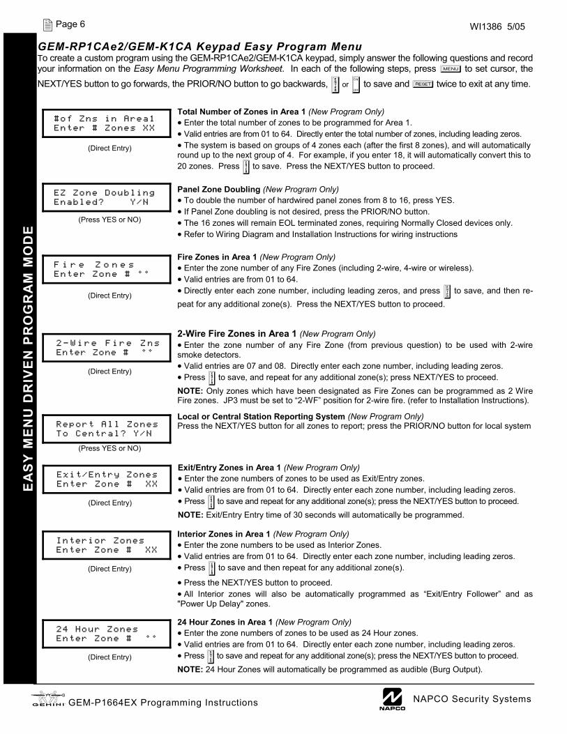
GEM-RP1CAe2/GEM-K1CA Keypad Easy Program Menu To create a custom program using the GEM-RP1CAe2/GEM-K1CA keypad, simply answer the following questions and record your information on the Easy Menu Programming Worksheet. In each of the following steps, press R to set cursor, the NEXT/YES button to go forwards, the PRIOR/NO button to go backwards, U or D to save and C twice to exit at any time.
Total Number of Zones in Area 1 (New Program Only) • Enter the total number of zones to be programmed for Area 1. • Valid entries are from 01 to 64. Directly enter the total number of zones, including leading zeros. • The system is based on groups of 4 zones each (after the first 8 zones), and will automatically round up to the next group of 4. For example, if you enter 18, it will automatically convert this to 20 zones. Press U to save. Press the NEXT/YES button to proceed. Panel Zone Doubling (New Program Only) • To double the number of hardwired panel zones from 8 to 16, press YES. • If Panel Zone doubling is not desired, press the PRIOR/NO button. • The 16 zones will remain EOL terminated zones, requiring Normally Closed devices only. • Refer to Wiring Diagram and Installation Instructions for wiring instructions Fire Zones in Area 1 (New Program Only) • Enter the zone number of any Fire Zones (including 2-wire, 4-wire or wireless). • Valid entries are from 01 to 64. • Directly enter each zone number, including leading zeros, and press U to save, and then re-peat for any additional zone(s). Press the NEXT/YES button to proceed. 2-Wire Fire Zones in Area 1 (New Program Only) • Enter the zone number of any Fire Zone (from previous question) to be used with 2-wire smoke detectors. • Valid entries are 07 and 08. Directly enter each zone number, including leading zeros. • Press U to save, and repeat for any additional zone(s); press NEXT/YES to proceed. NOTE: Only zones which have been designated as Fire Zones can be programmed as 2 Wire Fire zones. JP3 must be set to “2-WF” position for 2-wire fire. (refer to Installation Instructions). Local or Central Station Reporting System (New Program Only) Press the NEXT/YES button for all zones to report; press the PRIOR/NO button for local system Exit/Entry Zones in Area 1 (New Program Only) • Enter the zone numbers of zones to be used as Exit/Entry zones. • Valid entries are from 01 to 64. Directly enter each zone number, including leading zeros. • Press U to save and repeat for any additional zone(s); press the NEXT/YES button to proceed. NOTE: Exit/Entry Entry time of 30 seconds will automatically be programmed. Interior Zones in Area 1 (New Program Only) • Enter the zone numbers to be used as Interior Zones. • Valid entries are from 01 to 64. Directly enter each zone number, including leading zeros. • Press U to save and then repeat for any additional zone(s).
• Press the NEXT/YES button to proceed. • All Interior zones will also be automatically programmed as “Exit/Entry Follower” and as "Power Up Delay" zones. 24 Hour Zones in Area 1 (New Program Only) • Enter the zone numbers of zones to be used as 24 Hour zones. • Valid entries are from 01 to 64. Directly enter each zone number, including leading zeros. • Press U to save and repeat for any additional zone(s); press the NEXT/YES button to proceed. NOTE: 24 Hour Zones will automatically be programmed as audible (Burg Output).
EA
SY
ME
NU
DR
IVE
N P
RO
GR
AM
MO
DE
(Direct Entry)
#of Zns in Area1 Enter # Zones XX
(Press YES or NO)
EZ Zone Doubling Enabled? Y/N
(Direct Entry)
F i r e Z o n e s Enter Zone # °°
(Direct Entry)
2 - W i r e F i r e Z n s Enter Zone # °°
(Press YES or NO)
Report All Zones To Central? Y/N
(Direct Entry)
Exit/Entry Zones Enter Zone # XX
(Direct Entry)
Interior Zones Enter Zone # XX
(Direct Entry)
24 Hour Zones Enter Zone # °°
L NAPCO Security Systems X GEM-P1664EX Programming Instructions
Page 7 WI1386 5/05 E
AS
Y M
EN
U D
RIV
EN
PR
OG
RA
M M
OD
E
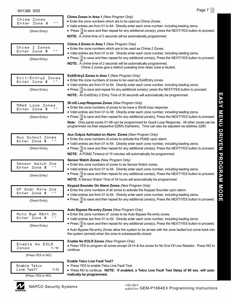
Chime Zones in Area 1 (New Program Only) • Enter the zone numbers which are to be used as Chime Zones. • Valid entries are from 01 to 64. Directly enter each zone number, including leading zeros. • Press U to save and then repeat for any additional zone(s), press the NEXT/YES button to proceed. NOTE: A chime time of 2 seconds will be automatically programmed. Chime 2 Zones in Area 1 (New Program Only) • Enter the zone numbers which are to be used as Chime 2 Zones. • Valid entries are from 01 to 64. Directly enter each zone number, including leading zeros. • Press U to save and then repeat for any additional zone(s), Press the NEXT/YES button to proceed. NOTE: A chime time of 2 seconds will be automatically programmed. Chime 2 zones give a distinct pulsating tone when zone is faulted. Exit/Entry2 Zones in Area 1 (New Program Only) • Enter the zone numbers of zones to be used as Exit/Entry zones. • Valid entries are from 01 to 64. Directly enter each zone number, including leading zeros. • Press U to save and repeat for any additional zone(s); press the NEXT/YES button to proceed. NOTE: An Exit/Entry 2 Entry Time of 30 seconds will automatically be programmed. 50 mS Loop Response Zones (New Program Only) • Enter the zone numbers of zones to be have a 50mS loop response. • Valid entries are from 01 to 08. Directly enter each zone number, including leading zeros. • Press U to save and then repeat for any additional zone(s), Press the NEXT/YES button to proceed. Note: Only panel zones 01-08 can be programmed for Quick Loop Response. All other zones can be programmed via their respective EZM's (hardwire). Time can also be adjusted via address 2280. Aux Output Activated on Alarm Zones (New Program Only) • Enter the zone numbers of zones to activate the PGM2 upon alarm. • Valid entries are from 01 to 64. Directly enter each zone number, including leading zeros. • Press U to save and then repeat for any additional zone(s), Press the NEXT/YES button to proceed. NOTE: A PGM2 Timeout of 15 minutes will automatically be programmed.
Sensor Watch Zones (New Program Only) • Enter the zone numbers of zones to be Sensor Watch zones. • Valid entries are from 01 to 64. Directly enter each zone number, including leading zeros. • Press U to save and then repeat for any additional zone(s), Press the NEXT/YES button to proceed. NOTE: A Sensor Watch Time of 24 hours will automatically be programmed.
Keypad Sounder On Alarm Zones (New Program Only) • Enter the zone numbers of all zones to activate the Keypad Sounder upon alarm. • Valid entries are from 01 to 64. Directly enter each zone number, including leading zeros. • Press U to save and then repeat for any additional zone(s), Press the NEXT/YES button to proceed. Auto Bypass Re-entry Zones (New Program Only) • Enter the zone numbers of zones to be Auto Bypass Re-entry zones. • Valid entries are from 01 to 64. Directly enter each zone number, including leading zeros. • Press U to save and then repeat for any additional zone(s), Press the NEXT/YES button to proceed. • Auto Bypass Re-entry Zones allow the system to be armed with the zone faulted but come back into the system (armed) when the zone is subsequently closed. Enable No EOLR Zones (New Program Only) • Press YES to program all zones except 24 Hr & fire zones for No End Of Line Resistor. Press NO to continue. Enable Telco Line Fault Test? • Press YES to enable Telco Line Fault Test. • Press NO to continue. NOTE: If enabled, a Telco Line Fault Test Delay of 60 sec. will auto-matically be programmed.
(Direct Entry)
Chime Zones Enter Zone # °°
(Direct Entry)
Chime 2 Zones Enter Zone # °°
(Direct Entry)
Exit/Entry2 Zones Enter Zone # °°
(Direct Entry)
50mS Loop Zones Enter Zone # °°
(Direct Entry)
Aux Output Zones Enter Zone # °°
(Direct Entry)
Sensor Watch Zns Enter Zone # °°
(Direct Entry)
KP Sndr Alrm Zns Enter Zone # °°
(Direct Entry)
Auto Byp REnt Zn Enter Zone # °°
(Press YES or NO)
Enable No EOLR Zones Y/N
(Press YES or NO)
Enable Telco Line Test? Y/N

X GEM-P1664EX Programming Instructions L NAPCO Security Systems
Page 8 WI1386 5/05 E
AS
Y M
EN
U D
RIV
EN
PR
OG
RA
M M
OD
E
Enable Burg Output Chirp on KeyFob? • Press the NEXT/YES button to enable Burg Output Chirp on KeyFob Arm / Disarm. • Press the PRIOR/NO button to continue. NOTE: The Burg Output will chirp once on Keyfob Arm and twice on Keyfob Disarm. Enable SIA CP-01 Features? • Press the NEXT/YES button to enable. • Press the PRIOR/NO button to continue. The SIA CP-01 Features are designed to reduce the incidence of false alarms. NOTE: Do not enable unless reporting, otherwise system trouble Fail to Communicate may occur.
Number of Keypads in Area 1 • Enter the total number of Keypads to be installed in Area 1. • Valid entries are from 01 to 07. Directly enter the number of keypads, including leading zeros. Press U to save. Press the NEXT/YES button to proceed. NOTE: Area 2-4 keypads must be assigned in Direct Address Programming. See Keypad Options.
Central Station Receiver 1 Telephone Number • Enter telephone number of up to 16 digits. • Press 1 through 9 for digits 1–9; G 0 for a zero and 0 for a blank (•). • Press G 1 through G 5 for letters B–F, respectively. • Pre-Dial Delay = “D” (G 4); Dial-Tone Detection = “E” (G 5). • Press U to save and press the NEXT/YES button to proceed. NOTE: Central Station Receiver 2 and 3 Telephone Numbers must be entered in Direct Ad-
dress Programming. See CS Receiver Options.
Central Station Receiver 1 Account Number • Enter an account number of up to four digits. • Press 0 through 9 for digits 0–9, and G 0 for a blank (•). • Press U to save and press the NEXT/YES button to proceed. NOTE: Central Station Receiver 2 and 3 Account Numbers must be entered in Direct Address Programming. See CS Reporting Options.
Central Station Receiver 1 Format • From the table at the right enter the receiver format. • Press 0 through 9, and G0 for blank (•). • Press G1 through G4 for letters B–E. • Press U to save and press the NEXT/YES button to proceed.
Enter User Codes (Press R to set cursor.) For default program, enter up to 64 User Codes, with Area 1, 2, 3 & 4 Options. • Press the (R) button once to set the cursor to the User Code. • Press 0 through 9 to enter a code from 3 to 6 digits, leave blank (•) any trailing boxes. • Press R to set the cursor to the Area 1 Options Level. Refer to the table below for available op-
tions. For Area 2 Options, press the R button once again. For Area 3 & 4 Options, press R a third and fourth time. • If “Enable Global Ambush Code” (Address 1422) is enabled and “Global Ambush Code” (Address 2045) is not left blank (•), do not program the
first two digits of ANY User Code the same as the “Global Ambush Code”. See Address 2045 further in this manual for more information. • Press U to save. Note: Duplicate User Codes are not allowed; therefore a duplicate Code entered in the LCD Window will erase when U is
pressed. To proceed to the next User Code, press R to set the cursor to the User Number and change it using the number buttons. Press the NEXT/YES button to proceed.
(Direct Entry)
Central Phone #
(Direct Entry)
Central Station Account # (____)
DATA ENTRY
CS RECEIVER 1 FORMAT
•(blank)
Ademco Slow, Silent Knight Slow
2 Radionics Fast 3 Silent Knight Fast 4 Radionics, DCI, Franklin Slow 5 Universal High Speed B SIA C Ademco Point ID E Pager
(Direct Entry)
See WI for Info Rcvr Format (0)
Enter user code-> U01 123 - 9-
User# User Code Area 1 Area 2
Example: Program a code of “2222” for user 02, with area 1 options of “Arm/Disarm” and “User Program”. Enter “2222” for a user code, “• (blank) 9” for area 1 options and “• (blank) •(blank)” for area 2 options.
(Direct Entry)
# Area 1 Keypads Enter # KPs 01
(Press YES or NO)
Enable SIA CP-01? Y/N
(Press YES or NO)
Enable Burg Out Chirp? Y/N
USER AREA OPTIONS DATA ENTRIES L R
blank(•) blank(•) Disabled blank(•) 1 Arm/Disarm blank(•) 2 Arm Only blank(•) 3 Service blank(•) 4 Access blank(•) 5 Ambush blank(•) Add 8 * User Program
4 blank(•) Bypass Enable
OPTION ENABLED
USER OPTIONS USER CODE
(UP TO 6 DIGITS) AREA 1
OPTIONS AREA 2
OPTIONS AREA 3
OPTIONS
AREA 4 OPTIONS

L NAPCO Security Systems X GEM-P1664EX Programming Instructions
Page 9 WI1386 5/05 E
AS
Y M
EN
U D
RIV
EN
PR
OG
RA
M M
OD
E
RF Transmitter Points (Press R to set cursor.) For each transmitter enter: (For wireless systems only. Also see Quick Method, which follows) • The zone number (01–64) to which the transmitter will be mapped. • The 6-digit RF ID # and 1-digit checksum number printed on the transmitter and box, • The point number (1–2); enter “9” for unsupervised (all points). • Press U to save and NEXT/YES button to proceed when all transmitters have been entered.
NOTE: When programming the ID Code number, “0” through ”9” = 0 through 9 ; A = G 0 ; B = G 1 ; C = G 2 ; D = G 3 ; E = G 4 and “F” = G 5.
Quick "Enroll" Method: If a receiver is already installed in the panel, transmitter wireless points can be programmed automatically (“enrolled”) using the following procedure. NOTE: The transmitter point will be enrolled only if the signal strength is 3 or greater. 1. Enter the zone number to which the transmitter point will be mapped. 2. Press B to enter the Enroll Mode. The red and green LEDs on the keypad will flash and the
window will display as shown at left. 3. Open the loop of the point that is to be programmed (GEM-TRANS2 only). 4. Install the transmitter battery. The keypad will beep to indicate that the point has been successfully
enrolled. Multi-point transmitters can be mapped to successive zones simultaneously.
Key Fob Transmitters as Arm/Disarm & Control Devices (Press R to set cursor). Key fobs can be programmed as “Arm/Disarm” devices using their On/Off buttons (refer to
WI752). For each Key Fob Transmitter, enter: • The Key Fob Transmitter number (01–8). • The area number to which transmitter is assigned (0 to disable keyfob, 1 through 4). • The 6-digit RF ID # and 1-digit checksum number printed on the transmitter and box, • The Aux 1 Option (see key fob aux 1 & aux 2 options). • The Aux 2 Option (see key fob aux 1 & aux 2 options). • Press U to save and NEXT/YES button to proceed when all key fobs have been entered.
NOTE: When programming the ID Code number, “0” through ”9” = 0 through 9 ; A = G 0 ; B = G 1 ; C = G 2 ; D = G 3 ; E = G 4 and “F” = G 5.
Z N # X M I T # + C S P Z n 0 1 - 0 0 0 0 0 0 : 0 - 0
Zone # Xmitter Check Point Mapped to ID Sum #
Z N # X M I T # + C S P Z n 0 1 - 0 0 0 0 0 0 : 0 - 0
Z N # X M I T # + C S P Z N 0 1 - E N R O L L : A - -
Example. A 2-point transmitter has the RF ID number 287613:1. Map point 1 to Zone 6 and point 2 to Zone 9. 1. Enter the Enroll mode as described above. 2. Enter Zone “06”. 3. Open point-1 loop. 4. Install the battery. The keypad will beep once to indicate that
one point has been programmed. (Transmitter 287613:1, point
1 will be mapped to Zone 6). 5. Enter Zone “09”. 6. Close point-1 loop and open point-2 loop. 7. Remove the transmitter battery, then re-install it. The keypad
will beep once to indicate that one point has been programmed. (Transmitter 287613:1, point 2 is mapped to Zone 9).
KEY FOB ZONE ASSIGNMENT: Key fobs can also be assigned to zones to allow multiple wireless panic buttons on one alarm system, each reporting to a central station, a pager or having a description on the keypad that describes the person holding the key fob, the location where the person holding the key fob is stationed, or the special purpose of the key fob button being depressed. See the next page on Key Fob Transmitters as Zone Input Devices .
K F A X M I T # + C S O P 0 1 - 0 0 0 0 0 0 0 : 0 0 0
KF Area Xmitter Check Aux # ID Sum 1&2
CHANGING OR CANCELING A CODE: To change any code, merely program over the existing code as described above and press U to save. Similarly, to
cancel a code, blank out each number of the code and press U to save.
AREA OPTIONS EXPLANATION Disabled User Code not active in this area.
Arm/Disarm Allows User Code to arm/disarm this area. Arm Only Prevents User Code from disarming this area. Service A Service Code has restricted arm/disarm rights; if an area is armed with a Service Code, a “MONITOR ON” appears on the GEM-RP2ASe2 keypad and the
area can be disarmed with any valid User Code, including a Service Code. If the area is armed with OTHER than a Service Code, it CANNOT be dis-armed with a Service Code. This is typically used to allow tradesmen access to premises under control of the owner.
Access This is normally used to activate a door strike while an area is disarmed. Also program “Access Control on PGM2. Output” (Address 0719) and “PGM2 Output Access Control Timeout” (Address 0711).
* User Program User Program Option is enabled. To enable User Program Option for any user, add 8 to the data entry for Area Option (see example). Then, User Pro-gramming can be performed at any Keypad by a user code with user program enabled.
Related User Options:“Enable Global Ambush Code” (Address 1422), “Global Ambush Code” (Address 2045) & “Enable Manager's Mode” (Address 1421).
Ambush There are two types of Ambush Codes: (1) A 2-digit code (prefix) that is entered immediately prior to (and as part of) the regular User Code and (2) A separate and unique User Code. Disarming with an Ambush Code will cause a silent report to be sent to a central station. Thus, should a user be forced to disarm, he can silently signal an emergency while appearing to be merely disarming the system.
Bypass Enable Security Bypass--Bypass is enabled only with a security code.
X GEM-P1664EX Programming Instructions L NAPCO Security Systems
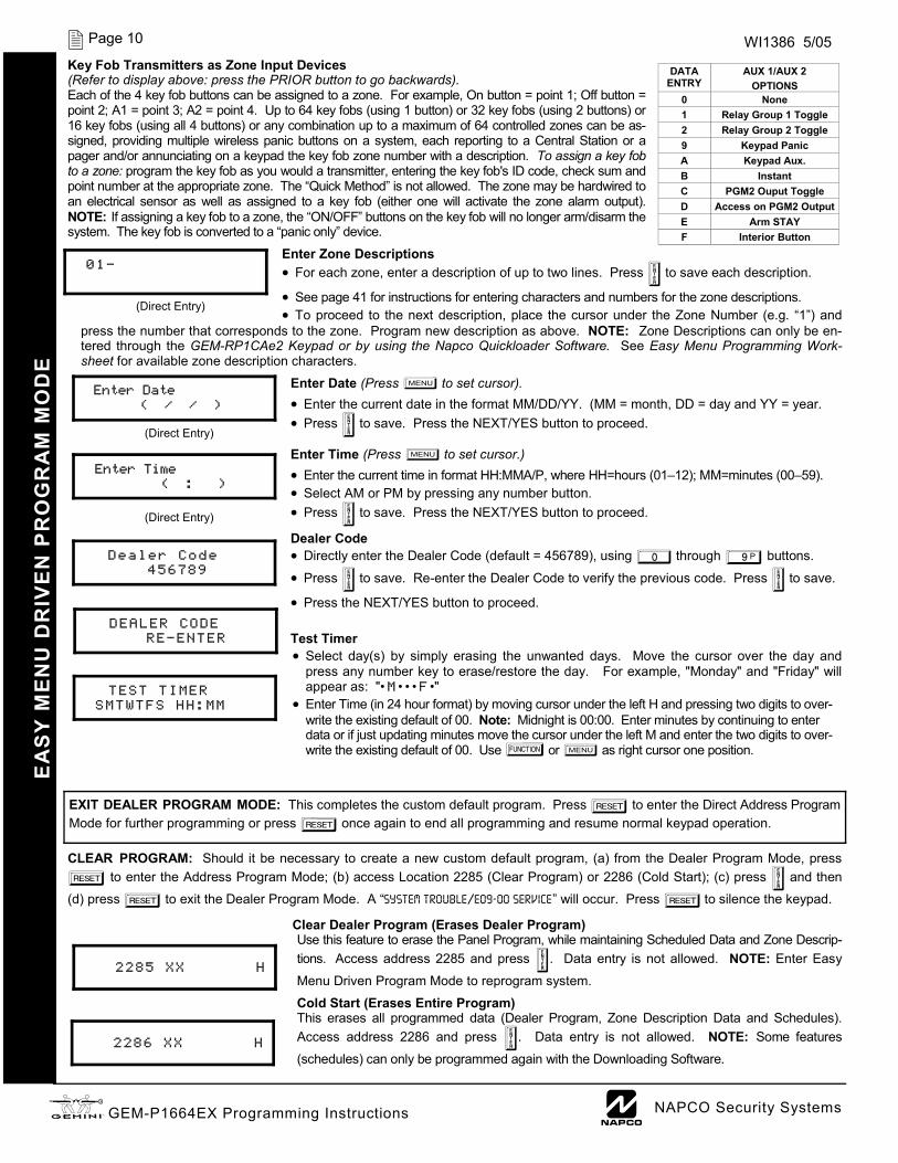
Page 10 WI1386 5/05 Key Fob Transmitters as Zone Input Devices (Refer to display above: press the PRIOR button to go backwards). Each of the 4 key fob buttons can be assigned to a zone. For example, On button = point 1; Off button = point 2; A1 = point 3; A2 = point 4. Up to 64 key fobs (using 1 button) or 32 key fobs (using 2 buttons) or 16 key fobs (using all 4 buttons) or any combination up to a maximum of 64 controlled zones can be as-signed, providing multiple wireless panic buttons on a system, each reporting to a Central Station or a pager and/or annunciating on a keypad the key fob zone number with a description. To assign a key fob to a zone: program the key fob as you would a transmitter, entering the key fob's ID code, check sum and point number at the appropriate zone. The “Quick Method” is not allowed. The zone may be hardwired to an electrical sensor as well as assigned to a key fob (either one will activate the zone alarm output). NOTE: If assigning a key fob to a zone, the “ON/OFF” buttons on the key fob will no longer arm/disarm the system. The key fob is converted to a “panic only” device.
Enter Zone Descriptions • For each zone, enter a description of up to two lines. Press U to save each description.
• See page 41 for instructions for entering characters and numbers for the zone descriptions. • To proceed to the next description, place the cursor under the Zone Number (e.g. “1”) and
press the number that corresponds to the zone. Program new description as above. NOTE: Zone Descriptions can only be en-tered through the GEM-RP1CAe2 Keypad or by using the Napco Quickloader Software. See Easy Menu Programming Work-sheet for available zone description characters.
Enter Date (Press R to set cursor). • Enter the current date in the format MM/DD/YY. (MM = month, DD = day and YY = year. • Press U to save. Press the NEXT/YES button to proceed.
Enter Time (Press R to set cursor.) • Enter the current time in format HH:MMA/P, where HH=hours (01–12); MM=minutes (00–59). • Select AM or PM by pressing any number button. • Press U to save. Press the NEXT/YES button to proceed.
Dealer Code • Directly enter the Dealer Code (default = 456789), using 0 through 9 buttons. • Press U to save. Re-enter the Dealer Code to verify the previous code. Press U to save.
• Press the NEXT/YES button to proceed.
Test Timer • Select day(s) by simply erasing the unwanted days. Move the cursor over the day and
press any number key to erase/restore the day. For example, "Monday" and "Friday" will appear as: "• M • • • F •"
• Enter Time (in 24 hour format) by moving cursor under the left H and pressing two digits to over-write the existing default of 00. Note: Midnight is 00:00. Enter minutes by continuing to enter data or if just updating minutes move the cursor under the left M and enter the two digits to over-write the existing default of 00. Use A or R as right cursor one position.
(Direct Entry)
Enter Date ( / / )
(Direct Entry)
Enter Time ( : )
Dealer Code
456789
DEALER CODE RE-ENTER
CLEAR PROGRAM: Should it be necessary to create a new custom default program, (a) from the Dealer Program Mode, press C to enter the Address Program Mode; (b) access Location 2285 (Clear Program) or 2286 (Cold Start); (c) press U and then (d) press C to exit the Dealer Program Mode. A “SYSTEM TROUBLE/E09-00 SERVICE” will occur. Press C to silence the keypad.
Clear Dealer Program (Erases Dealer Program) Use this feature to erase the Panel Program, while maintaining Scheduled Data and Zone Descrip-tions. Access address 2285 and press U. Data entry is not allowed. NOTE: Enter Easy Menu Driven Program Mode to reprogram system.
Cold Start (Erases Entire Program) This erases all programmed data (Dealer Program, Zone Description Data and Schedules). Access address 2286 and press U. Data entry is not allowed. NOTE: Some features (schedules) can only be programmed again with the Downloading Software.
EA
SY
ME
NU
DR
IVE
N P
RO
GR
AM
MO
DE
DATA ENTRY
AUX 1/AUX 2 OPTIONS
0 None 1 Relay Group 1 Toggle 2 Relay Group 2 Toggle 9 Keypad Panic A Keypad Aux. B Instant C PGM2 Ouput Toggle D Access on PGM2 Output E Arm STAY F Interior Button
(Direct Entry)
01-
EXIT DEALER PROGRAM MODE: This completes the custom default program. Press C to enter the Direct Address Program Mode for further programming or press C once again to end all programming and resume normal keypad operation.
2285 XX H
2286 XX H
TEST TIMER
SMTWTFS HH:MM

L NAPCO Security Systems X GEM-P1664EX Programming Instructions
Page 11 WI1386 5/05
DIRECT ADDRESS OVERVIEW Direct Address Programming allows you to go directly to the address locations (up to 2287) and change the data entries manually in order to customize your control panel options. Whereas the Easy Menu Program Mode guides you through limited selections to get you started, Direct Address Program Mode allows you to change all options directly. It con-sists of up to 2287 address locations each with data entry locations as shown in the following diagram (below left). The data entry location accepts data in one of three formats: Binary, Decimal and Hexadecimal (explained below in "Address Mode Displays"). The following diagram (below right) illustrates a Decimal format data entry location (using a GEM-RP1CAe2 keypad). ADDRESS MODE DISPLAYS There are three types of address displays when programming in Direct Entry Program Mode, as follows:
A) Binary (Bit) Format Settings (such as Zone Features) display and accept data in "number" format. For example, Zone Features are turned on by the pressing of keypad buttons 1 through 8, with the activated Zone(s) displaying the corresponding decimal digit (replacing deactivated zones which are signified by dashes).
EXAMPLE: BIT Format with the GEM-RP1CAe2: Program Zones 2, 4, 5 and 7 as Exit/Entry Follower Zones.
DETERMINE THE DATA ENTRIES 1. Referring to ZONE FEATURES in the Programming Worksheets that follow, the Exit/Entry Follower for Zones 1
through 8 are located at address 0916.
DATA ENTRY LOCATION
ADDRESS LOCATIONS
0000
0000 TO
2287
DATA ENTRY LOCATION: (One of three formats):
• Binary (Bit) • Decimal • Hexadecimal
DIRECT ADDRESS PROGRAM MODE D
irect Address Program M
ode
GEM-RP1CAe2 Keypad Display Example
0 0 0 0 0 6 0 D
1 2
= ADDRESS LOCATION 1 2 = DATA ENTRY LOCATION
0916 - - - - - - - - B 0916 - 2 - 4 5 - 7 - B
DATA ENTRY LOCATION: Binary (Bit) Format
• No zones yet activated
Address 0916
"Exit/Entry Follower"
Address 0916
"Exit/Entry Follower"
DATA ENTRY LOCATION: Binary (Bit) Format
Press 2 4 5 and 7 in order to acti-vate Zones 2, 4, 5, and 7. (The "B" on the right indi-cates "Binary" format). Because "bit numbers" range from 0-7, these "option numbers" 2,4,5 and 7 correspond to "bit numbers" 1,3,4 and 6, respec-tively.
X GEM-P1664EX Programming Instructions L NAPCO Security Systems
Page 12 WI1386 5/05
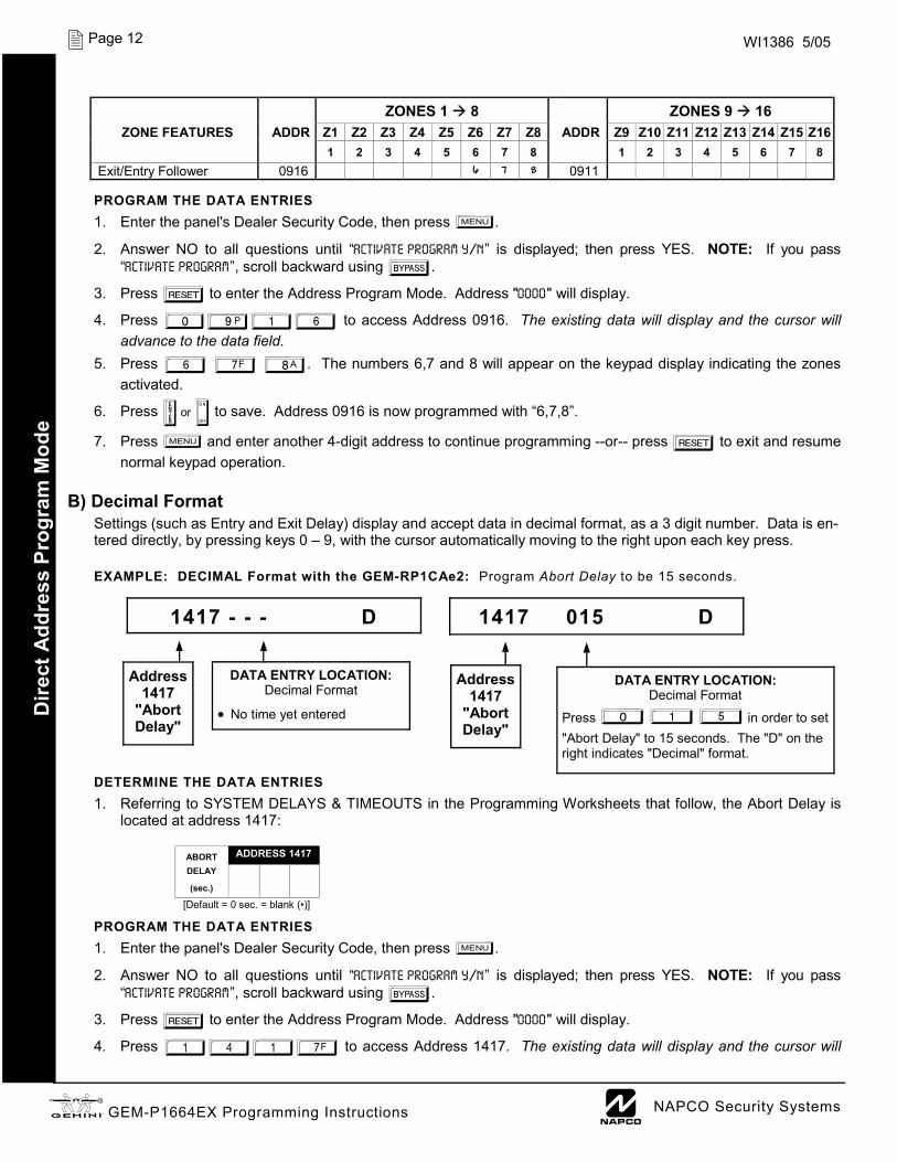
PROGRAM THE DATA ENTRIES 1. Enter the panel's Dealer Security Code, then press R.
2. Answer NO to all questions until “ACTIVATE PROGRAM Y/N” is displayed; then press YES. NOTE: If you pass “ACTIVATE PROGRAM”, scroll backward using B.
3. Press C to enter the Address Program Mode. Address "0000" will display.
4. Press 0916 to access Address 0916. The existing data will display and the cursor will advance to the data field.
5. Press 6 7 8. The numbers 6,7 and 8 will appear on the keypad display indicating the zones activated.
6. Press U or D to save. Address 0916 is now programmed with “6,7,8”.
7. Press R and enter another 4-digit address to continue programming --or-- press C to exit and resume normal keypad operation.
B) Decimal Format
Settings (such as Entry and Exit Delay) display and accept data in decimal format, as a 3 digit number. Data is en-tered directly, by pressing keys 0 – 9, with the cursor automatically moving to the right upon each key press. EXAMPLE: DECIMAL Format with the GEM-RP1CAe2: Program Abort Delay to be 15 seconds. DETERMINE THE DATA ENTRIES 1. Referring to SYSTEM DELAYS & TIMEOUTS in the Programming Worksheets that follow, the Abort Delay is
located at address 1417: PROGRAM THE DATA ENTRIES 1. Enter the panel's Dealer Security Code, then press R.
2. Answer NO to all questions until “ACTIVATE PROGRAM Y/N” is displayed; then press YES. NOTE: If you pass “ACTIVATE PROGRAM”, scroll backward using B.
3. Press C to enter the Address Program Mode. Address "0000" will display.
4. Press 1417 to access Address 1417. The existing data will display and the cursor will
Dire
ct A
ddre
ss P
rogr
am M
ode
1417 - - - D 1417 015 D
ZONES 1 8 ZONES 9 16 ZONE FEATURES ADDR Z1 Z2 Z3 Z4 Z5 Z6 Z7 Z8 ADDR Z9 Z10 Z11 Z12 Z13 Z14 Z15 Z16
1 2 3 4 5 6 7 8 1 2 3 4 5 6 7 8 Exit/Entry Follower 0916 6 7 8 0911
DATA ENTRY LOCATION: Decimal Format
• No time yet entered
Address 1417
"Abort Delay"
DATA ENTRY LOCATION: Decimal Format
Press 0 1 5 in order to set "Abort Delay" to 15 seconds. The "D" on the right indicates "Decimal" format.
ABORT ADDRESS 1417 DELAY (sec.)
[Default = 0 sec. = blank (•)]
Address 1417
"Abort Delay"

L NAPCO Security Systems X GEM-P1664EX Programming Instructions
Page 13 WI1386 5/05 D
irect Address Program M
ode advance to the data field.
5. Press 015. The numbers 015 will appear on the keypad display indicating the number of seconds entered.
6. Press U or D to save. Address 1417 is now programmed with a 15-second Abort Delay.
7. Press R and enter another 4-digit address to continue programming--or--press C to exit and re-sume normal keypad operation.
C) Hexadecimal Format
Data such as Report Codes displays and accepts data by means of a Hexadecimal display. Data is entered di-rectly, by pressing keys 1 – 9, G0 for zero, and G 1 through G 5 for hex B through F (11-15), with the cursor automatically moving to the right upon key press. See table below. EXAMPLE: HEXADECIMAL Format with the GEM-RP1CAe2: Program Chime Timeout to be 2 seconds.
DETERMINE THE DATA ENTRIES 1. Referring to SYSTEM DELAYS & TIMEOUTS in the Programming Worksheets that follow, the Chime Timeout
is located at address 1418. In the "Chime Timeout Options" table, the data entries needed to assign a time-out of 2 seconds are "blank" and "8".
ENTRY TOTAL
PRESS N KEYPAD DISPLAYS
ENTRY TOTAL
PRESS N KEYPAD DISPLAYS
blank 0 • 8 8 8
1 1 1 9 9 9
2 2 2 10 G 0 0
3 3 3 11 G 1 B
4 4 4 12 G 2 C
5 5 5 13 G 3 D
6 6 6 14 G 4 E
7 7 7 15 G 5 F
HEXADECIMAL ENTRIES
CHIME ADDRESS 1418 TIMEOUT (¼sec.)
[Default = 2 ¼sec. = ½ sec.]
DATA ENTRY LOCATION: Decimal Format
• No time yet entered
DATA ENTRY LOCATION: Decimal Format
Press 0 8 in order to set "Chime Timeout" to 2 seconds. The "H" on the right indicates "Hexadecimal" format.
Address 1418
"Chime Timeout"
1418 - - H 1418 - 8 H
Address 1418
"Chime Timeout"
2 seconds
CHIME TIMEOUT OPTIONS TIMEOUT
LEFT RIGHT blank (•) blank (•) 0 x ¼sec. = 0 sec. blank (•) 2 2 x ¼sec. = ½ sec. blank (•) 3 3 x ¼sec. = ¾ sec. blank (•) 4 4 x ¼sec. = 1 sec. blank (•) 5 5 x ¼sec. = 1.25 sec. blank (•) 6 6 x ¼sec. = 1.5 sec. blank (•) 7 7 x ¼sec. = 1.75 sec. blank (•) 8 8 x ¼sec. = 2 sec.
F F 255 x ¼sec. = 63.25
DATA ENTRIES
X GEM-P1664EX Programming Instructions L NAPCO Security Systems
Page 14 WI1386 5/05 D
irect
Add
ress
Pro
gram
Mod
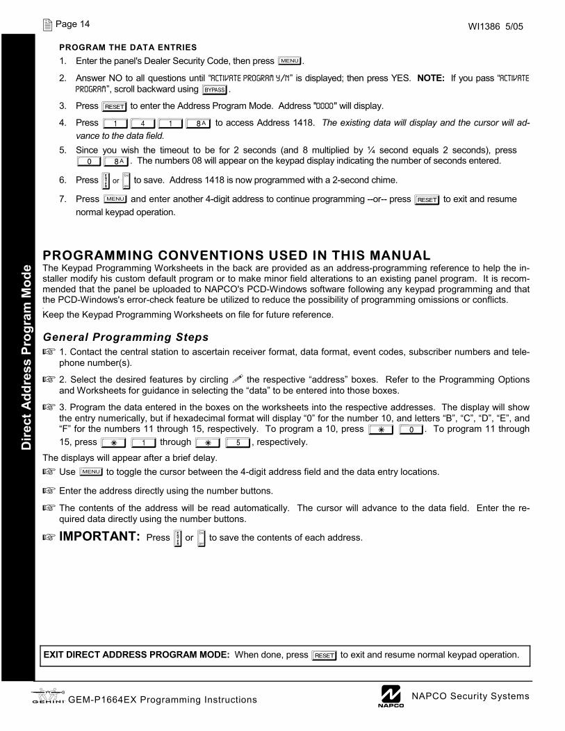
e PROGRAM THE DATA ENTRIES 1. Enter the panel's Dealer Security Code, then press R.
2. Answer NO to all questions until “ACTIVATE PROGRAM Y/N” is displayed; then press YES. NOTE: If you pass “ACTIVATE PROGRAM”, scroll backward using B.
3. Press C to enter the Address Program Mode. Address "0000" will display.
4. Press 1418 to access Address 1418. The existing data will display and the cursor will ad-vance to the data field.
5. Since you wish the timeout to be for 2 seconds (and 8 multiplied by ¼ second equals 2 seconds), press 08. The numbers 08 will appear on the keypad display indicating the number of seconds entered.
6. Press U or D to save. Address 1418 is now programmed with a 2-second chime.
7. Press R and enter another 4-digit address to continue programming --or-- press C to exit and resume normal keypad operation.
PROGRAMMING CONVENTIONS USED IN THIS MANUAL The Keypad Programming Worksheets in the back are provided as an address-programming reference to help the in-staller modify his custom default program or to make minor field alterations to an existing panel program. It is recom-mended that the panel be uploaded to NAPCO's PCD-Windows software following any keypad programming and that the PCD-Windows's error-check feature be utilized to reduce the possibility of programming omissions or conflicts. 3
Keep the Keypad Programming Worksheets on file for future reference. General Programming Steps
1. Contact the central station to ascertain receiver format, data format, event codes, subscriber numbers and tele-phone number(s).
2. Select the desired features by circling the respective “address” boxes. Refer to the Programming Options and Worksheets for guidance in selecting the “data” to be entered into those boxes.
3. Program the data entered in the boxes on the worksheets into the respective addresses. The display will show the entry numerically, but if hexadecimal format will display “0” for the number 10, and letters “B”, “C”, “D”, “E”, and “F” for the numbers 11 through 15, respectively. To program a 10, press G 0. To program 11 through 15, press G 1 through G 5, respectively.
The displays will appear after a brief delay. Use R to toggle the cursor between the 4-digit address field and the data entry locations.
Enter the address directly using the number buttons.
The contents of the address will be read automatically. The cursor will advance to the data field. Enter the re-quired data directly using the number buttons.
IMPORTANT: Press U or D to save the contents of each address.
EXIT DIRECT ADDRESS PROGRAM MODE: When done, press C to exit and resume normal keypad operation.
L NAPCO Security Systems X GEM-P1664EX Programming Instructions
Page 15 WI1386 5/05
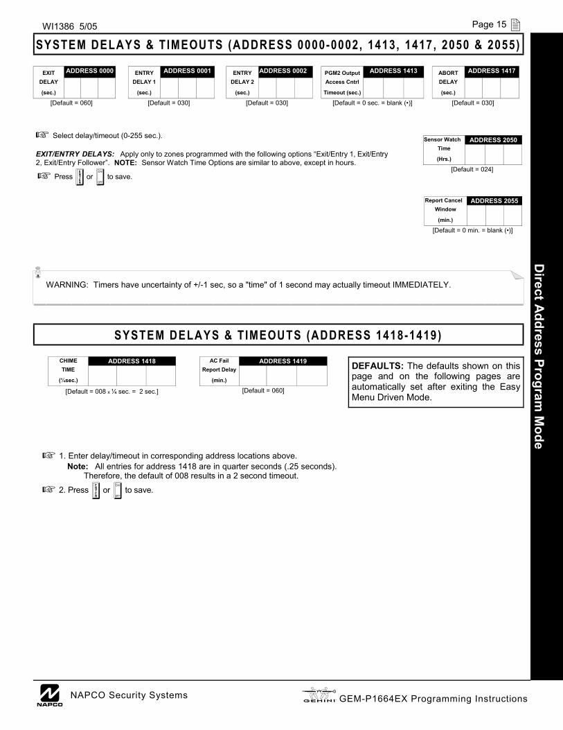
SYSTEM DELAYS & TIMEOUTS (ADDRESS 0000-0002, 1413, 1417, 2050 & 2055) D
irect Address Program M
ode
WARNING: Timers have uncertainty of +/-1 sec, so a "time" of 1 second may actually timeout IMMEDIATELY.
Select delay/timeout (0-255 sec.). EXIT/ENTRY DELAYS: Apply only to zones programmed with the following options “Exit/Entry 1, Exit/Entry 2, Exit/Entry Follower”. NOTE: Sensor Watch Time Options are similar to above, except in hours.
Press U or D to save.
SYSTEM DELAYS & TIMEOUTS (ADDRESS 1418-1419)
DEFAULTS: The defaults shown on this page and on the following pages are automatically set after exiting the Easy Menu Driven Mode.
1. Enter delay/timeout in corresponding address locations above. Note: All entries for address 1418 are in quarter seconds (.25 seconds).
Therefore, the default of 008 results in a 2 second timeout.
2. Press U or D to save.
EXIT ADDRESS 0000 DELAY (sec.)
[Default = 060]
ENTRY ADDRESS 0001
DELAY 1 (sec.)
[Default = 030]
PGM2 Output ADDRESS 1413 Access Cntrl
Timeout (sec.)
[Default = 0 sec. = blank (•)]
ABORT ADDRESS 1417 DELAY (sec.)
[Default = 030]
Sensor Watch ADDRESS 2050 Time (Hrs.)
[Default = 024]
Report Cancel ADDRESS 2055 Window
(min.)
[Default = 0 min. = blank (•)]
AC Fail ADDRESS 1419 Report Delay
(min.)
[Default = 060]
CHIME ADDRESS 1418 TIME
(¼sec.)
[Default = 008 x ¼ sec. = 2 sec.]
ENTRY ADDRESS 0002 DELAY 2
(sec.)
[Default = 030]
X GEM-P1664EX Programming Instructions L NAPCO Security Systems
Page 16 WI1386 5/05
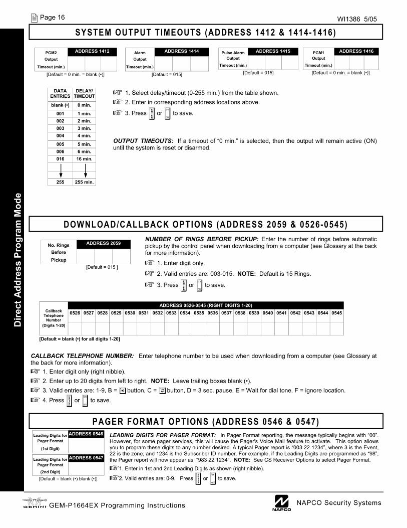
SYSTEM OUTPUT TIMEOUTS (ADDRESS 1412 & 1414-1416)
1. Select delay/timeout (0-255 min.) from the table shown. 2. Enter in corresponding address locations above.
3. Press U or D to save.
OUTPUT TIMEOUTS: If a timeout of “0 min.” is selected, then the output will remain active (ON) until the system is reset or disarmed.
DOWNLOAD/CALLBACK OPTIONS (ADDRESS 2059 & 0526-0545) NUMBER OF RINGS BEFORE PICKUP: Enter the number of rings before automatic pickup by the control panel when downloading from a computer (see Glossary at the back for more information).
1. Enter digit only.
2. Valid entries are: 003-015. NOTE: Default is 15 Rings.
3. Press U or D to save.
CALLBACK TELEPHONE NUMBER: Enter telephone number to be used when downloading from a computer (see Glossary at the back for more information).
1. Enter digit only (right nibble). 2. Enter up to 20 digits from left to right. NOTE: Leave trailing boxes blank (•). 3. Valid entries are: 1-9, B = *button, C = #button, D = 3 sec. pause, E = Wait for dial tone, F = ignore location. 4. Press U or D to save.
PAGER FORMAT OPTIONS (ADDRESS 0546 & 0547) LEADING DIGITS FOR PAGER FORMAT: In Pager Format reporting, the message typically begins with “00”. However, for some pager services, this will cause the Pager's Voice Mail feature to activate. This option allows you to program these digits to any number desired. A typical Pager report is “003 22 1234”, where 3 is the Event, 22 is the zone, and 1234 is the Subscriber ID number. For example, if the Leading Digits are programmed as “98”, the Pager report will now appear as “983 22 1234”. NOTE: See CS Receiver Options to select Pager Format.
1. Enter in 1st and 2nd Leading Digits as shown (right nibble).
2. Valid entries are: 0-9. Press U or D to save.
Callback
Telephone Number
ADDRESS 0526-0545 (RIGHT DIGITS 1-20) 0526 0527 0528 0529 0530 0531 0532 0533 0534 0535 0536 0537 0538 0539 0540 0541 0542 0543 0544 0545
(Digits 1-20)
[Default = blank (•) for all digits 1-20]
No. Rings ADDRESS 2059
Before Pickup
[Default = 015 ]
PGM2 ADDRESS 1412 Output
Timeout (min.)
[Default = 0 min. = blank (•)]
Alarm ADDRESS 1414 Output
Timeout (min.)
[Default = 015]
Pulse Alarm ADDRESS 1415
Output Timeout (min.)
[Default = 015]
PGM1 ADDRESS 1416 Output
Timeout (min.)
[Default = 0 min. = blank (•)]
DELAY/ TIMEOUT
blank (•) 0 min.
001 1 min. 002 2 min. 003 3 min. 004 4 min.
005 5 min. 006 6 min. 016 16 min.
255 255 min.
DATA ENTRIES
Leading Digits for ADDRESS 0546 Pager Format
(1st Digit)
Leading Digits for ADDRESS 0547 Pager Format
(2nd Digit) [Default = blank (•) blank (•)]
Dire
ct A
ddre
ss P
rogr
am M
ode

L NAPCO Security Systems X GEM-P1664EX Programming Instructions
Page 17 WI1386 5/05
GLOBAL SYSTEM EVENT/TROUBLE
SYSTEM RESPONSE ACTIVATED BY GLOBAL
EVENT/TROUBLE
ADDR TEST TIMER
TELCO FAILURE
RF RCVR. TROUBLE
MEMORY FAILURE
LOW BATTERY AC FAIL EZM
TAMPER Bell
Superv
1 2 3 4 5 6 7 8 Alarm Output 0836 Pulsed Alarm Output 0837 PGM1 Output 0838 PGM2 Output 0839 Report Event Telco 1 0840 Report Restore Telco 1 0841 Report Event Telco 3 0842 Report Restore Telco 3 0843
SYSTEM OPTIONS (ADDRESS 0836-0871 & 2045)
1. Select the desired option entering the option number (1-8) for each digit. 2. Enter corresponding option number in address location.
NOTE: Dark shaded data value box shows option not available. Press U or D to save.
GLOBAL AMBUSH CODE: It is the 2-digits entered immediately prior to the regular disarm code. If “Enable Global Ambush Code” (Address 1422) is selected and Address 2045 is left blank (•), then the 2-digit Global Ambush Code is “99”. If “Enable Global Ambush Code” is selected and Address 2045 is not left blank (•), then the 2-digit Global Ambush Code is the two digits entered in address 2045.
Enter in address location (both 1st and 2nd digits); valid entries are 1-9.
Press U or D to save.
Direct Address Program
Mode
[Default = blank (•) blank (•)]
Global 1st digit 2nd digit
Ambush Code
ADDRESS 2045
SYSTEM RESPONSE ACTIVATED BY AREA 1
EVENT/TROUBLE
AREA 1 SYSTEM EVENT/TROUBLE
ADDR AMBUSH KEYPAD PANIC
KEYPAD FIRE
KEYPAD AUX.
KEYPAD TAMPER
FAIL TO OPEN
FAIL TO CLOSE
Keyfob Low Batt
1 2 3 4 5 6 7 8
Pulsed Alarm Output 0856 Alarm Output 0857 PGM1 Output 0858 PGM2 Output 0860 Report Event Telco 1 0861 Report Event Telco 3 0863
[Default = blank (•) from address 0856-0863]
SYSTEM RESPONSE ACTIVATED BY AREA 2
EVENT/TROUBLE
AREA 2 SYSTEM EVENT/TROUBLE
ADDR AMBUSH KEYPAD PANIC
KEYPAD FIRE
KEYPAD AUX.
KEYPAD TAMPER
FAIL TO OPEN
FAIL TO CLOSE
Keyfob Low Batt
1 2 3 4 5 6 7 8
Pulsed Alarm Output 0864 Alarm Output 0865 PGM1 Output 0866 PGM2 Output 0868 Report Event Telco 1 0869 Report Event Telco 3 0871
[Default = blank (•) blank (•) from address 0864-0871]
[Default = blank (•) from address 0836-0843]. Note: If Test Timer is enabled (above), Digital Dialer Test is also enabled.
X GEM-P1664EX Programming Instructions L NAPCO Security Systems
Page 18 WI1386 5/05
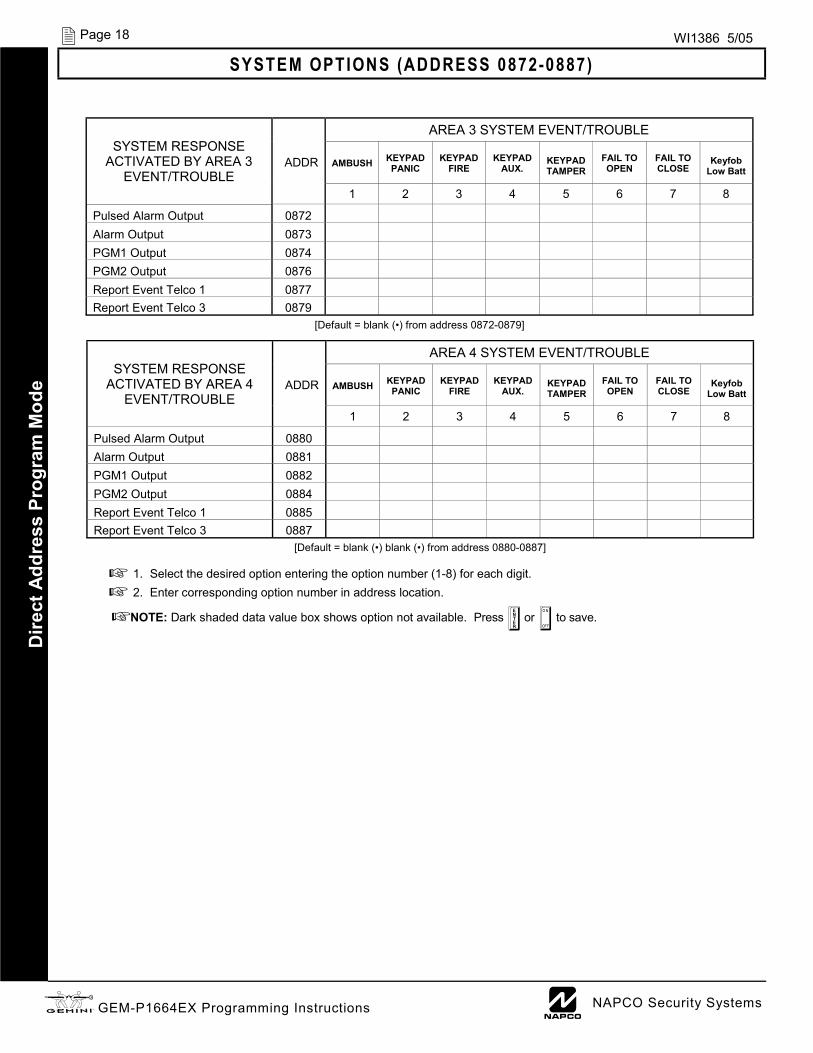
SYSTEM OPTIONS (ADDRESS 0872-0887)
1. Select the desired option entering the option number (1-8) for each digit. 2. Enter corresponding option number in address location.
NOTE: Dark shaded data value box shows option not available. Press U or D to save.
Dire
ct A
ddre
ss P
rogr
am M
ode
SYSTEM RESPONSE ACTIVATED BY AREA 3
EVENT/TROUBLE
AREA 3 SYSTEM EVENT/TROUBLE
ADDR AMBUSH KEYPAD PANIC
KEYPAD FIRE
KEYPAD AUX.
KEYPAD TAMPER
FAIL TO OPEN
FAIL TO CLOSE
Keyfob Low Batt
1 2 3 4 5 6 7 8
Pulsed Alarm Output 0872 Alarm Output 0873 PGM1 Output 0874 PGM2 Output 0876 Report Event Telco 1 0877 Report Event Telco 3 0879
[Default = blank (•) from address 0872-0879]
SYSTEM RESPONSE ACTIVATED BY AREA 4
EVENT/TROUBLE
AREA 4 SYSTEM EVENT/TROUBLE
ADDR AMBUSH KEYPAD PANIC
KEYPAD FIRE
KEYPAD AUX.
KEYPAD TAMPER
FAIL TO OPEN
FAIL TO CLOSE
Keyfob Low Batt
1 2 3 4 5 6 7 8
Pulsed Alarm Output 0880 Alarm Output 0881 PGM1 Output 0882 PGM2 Output 0884 Report Event Telco 1 0885 Report Event Telco 3 0887
[Default = blank (•) blank (•) from address 0880-0887]
L NAPCO Security Systems X GEM-P1664EX Programming Instructions
Page 19 WI1386 5/05
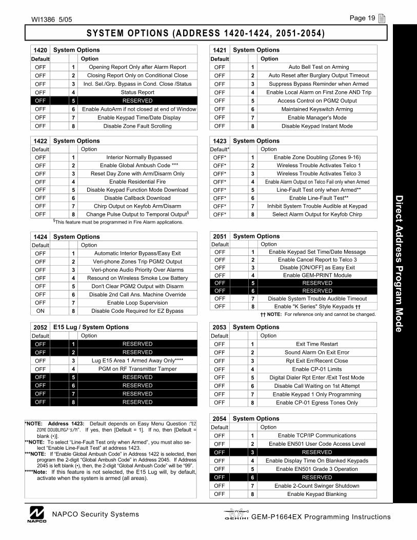
SYSTEM OPTIONS (ADDRESS 1420-1424, 2051-2054)
*NOTE: Address 1423: Default depends on Easy Menu Question :“EZ ZONE DOUBLING? Y/N”. If yes, then [Default = 1]. If no, then [Default = blank (•)].
**NOTE: To select “Line-Fault Test only when Armed”, you must also se-lect “Enable Line-Fault Test” at address 1423.
***NOTE: If “Enable Global Ambush Code” in Address 1422 is selected, then program the 2-digit “Global Ambush Code” in Address 2045. If Address 2045 is left blank (•), then, the 2-digit “Global Ambush Code” will be “99”.
****Note: If this feature is not selected, the E15 Lug will, by default, activate when the system is armed (all areas).
1420 System Options 1421 Default Option Default Option OFF 1 Opening Report Only after Alarm Report OFF 1 Auto Bell Test on Arming OFF 2 Closing Report Only on Conditional Close OFF 2 Auto Reset after Burglary Output Timeout OFF 3 Incl. Sel./Grp. Bypass in Cond. Close /Status OFF 3 Suppress Bypass Reminder when Armed OFF 4 Status Report OFF 4 Enable Local Alarm on First Zone AND Trip OFF 5 RESERVED OFF 5 Access Control on PGM2 Output OFF 6 Enable AutoArm if not closed at end of Window OFF 6 Maintained Keyswitch Arming OFF 7 Enable Keypad Time/Date Display OFF 7 Enable Manager's Mode OFF 8 Disable Zone Fault Scrolling OFF 8 Disable Keypad Instant Mode
System Options
1422 System Options 1423 System Options Default Option Default* Option OFF 1 Interior Normally Bypassed OFF* 1 Enable Zone Doubling (Zones 9-16) OFF 2 Enable Global Ambush Code *** OFF* 2 Wireless Trouble Activates Telco 1 OFF 3 Reset Day Zone with Arm/Disarm Only OFF* 3 Wireless Trouble Activates Telco 3 OFF 4 Enable Residential Fire OFF* 4 Enable Alarm Output on Telco Fail only when Armed OFF 5 Disable Keypad Function Mode Download OFF* 5 Line-Fault Test only when Armed** OFF 6 Disable Callback Download OFF* 6 Enable Line-Fault Test** OFF 7 Chirp Output on Keyfob Arm/Disarm OFF* 7 Inhibit System Trouble Audible at Keypad OFF 8 Change Pulse Output to Temporal Output§ OFF* 8 Select Alarm Output for Keyfob Chirp §This feature must be programmed in Fire Alarm applications.
2051 System Options Default Option
OFF 1 Enable Keypad Set Time/Date Message OFF 2 Enable Cancel Report to Telco 3 OFF 3 Disable [ON/OFF] as Easy Exit OFF 4 Enable GEM-PRINT Module OFF 5 RESERVED OFF 6 RESERVED OFF 7 Disable System Trouble Audible Timeout OFF 8 Enable "K Series" Style Keypads ††
†† NOTE: For reference only and cannot be changed.
1424 Default Option OFF 1 Automatic Interior Bypass/Easy Exit OFF 2 Veri-phone Zones Trip PGM2 Output OFF 3 Veri-phone Audio Priority Over Alarms OFF 4 Resound on Wireless Smoke Low Battery OFF 5 Don't Clear PGM2 Output with Disarm OFF 6 Disable 2nd Call Ans. Machine Override OFF 7 Enable Loop Supervision ON 8 Disable Code Required for EZ Bypass
System Options
Direct Address Program
Mode 2053
Default Option OFF 1 Exit Time Restart OFF 2 Sound Alarm On Exit Error OFF 3 Rpt Exit Err/Recent Close OFF 4 Enable CP-01 Limits OFF 5 Digital Dialer Rpt Enter /Exit Test Mode OFF 6 Disable Call Waiting on 1st Attempt OFF 7 Enable Keypad 1 Only Programming OFF 8 Enable CP-01 Egress Tones Only
System Options
2054 Default Option
OFF 1 Enable TCP/IP Communications OFF 2 Enable EN501 User Code Access Level OFF 3 RESERVED OFF 4 Enable Display Time On Blanked Keypads OFF 5 Enable EN501 Grade 3 Operation OFF 6 RESERVED OFF 7 Enable 2-Count Swinger Shutdown OFF 8 Enable Keypad Blanking
System Options
2052 E15 Lug / System Options Default Option OFF 1 RESERVED OFF 2 RESERVED OFF 3 Lug E15 Area 1 Armed Away Only**** OFF 4 PGM on RF Transmitter Tamper OFF 5 RESERVED OFF 6 RESERVED OFF 7 RESERVED OFF 8 RESERVED
X GEM-P1664EX Programming Instructions L NAPCO Security Systems
Page 20 WI1386 5/05 D
irect
Add
ress
Pro
gram
Mod
e
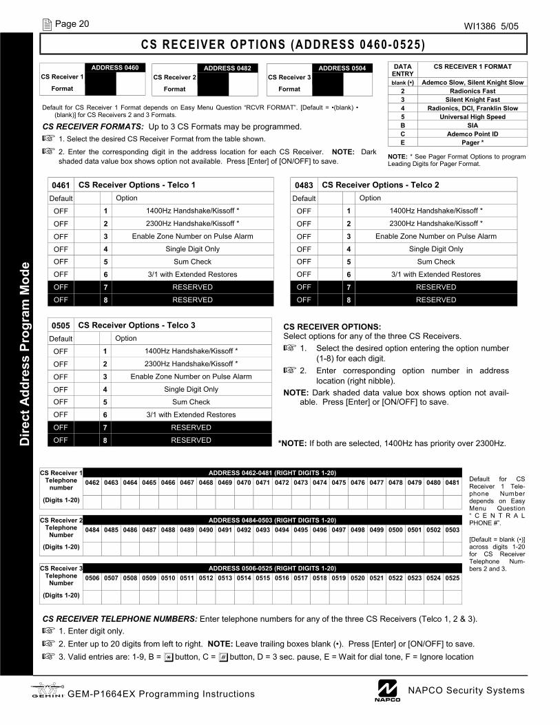
NOTE: * See Pager Format Options to program Leading Digits for Pager Format.
CS RECEIVER OPTIONS (ADDRESS 0460-0525)
Default for CS Receiver 1 Format depends on Easy Menu Question “RCVR FORMAT”. [Default = •(blank) •(blank)] for CS Receivers 2 and 3 Formats.
CS RECEIVER FORMATS: Up to 3 CS Formats may be programmed. 1. Select the desired CS Receiver Format from the table shown.
2. Enter the corresponding digit in the address location for each CS Receiver. NOTE: Dark shaded data value box shows option not available. Press [Enter] of [ON/OFF] to save.
DATA ENTRY
CS RECEIVER 1 FORMAT
blank (•) Ademco Slow, Silent Knight Slow 2 Radionics Fast 3 Silent Knight Fast 4 Radionics, DCI, Franklin Slow 5 Universal High Speed B SIA C Ademco Point ID E Pager *
CS RECEIVER OPTIONS: Select options for any of the three CS Receivers.
1. Select the desired option entering the option number (1-8) for each digit. 2. Enter corresponding option number in address location (right nibble).
NOTE: Dark shaded data value box shows option not avail-able. Press [Enter] or [ON/OFF] to save.
*NOTE: If both are selected, 1400Hz has priority over 2300Hz.
CS RECEIVER TELEPHONE NUMBERS: Enter telephone numbers for any of the three CS Receivers (Telco 1, 2 & 3). 1. Enter digit only. 2. Enter up to 20 digits from left to right. NOTE: Leave trailing boxes blank (•). Press [Enter] or [ON/OFF] to save. 3. Valid entries are: 1-9, B = *button, C = #button, D = 3 sec. pause, E = Wait for dial tone, F = Ignore location
Default for CS Receiver 1 Tele-phone Number depends on Easy Menu Question “ C E N T R A L PHONE #”. [Default = blank (•)] across digits 1-20 for CS Receiver Telephone Num-bers 2 and 3.
ADDRESS 0460 CS Receiver 1
Format
ADDRESS 0482 CS Receiver 2
Format
ADDRESS 0504 CS Receiver 3
Format
ADDRESS 0462-0481 (RIGHT DIGITS 1-20) 0462 0463 0464 0465 0466 0467 0468 0469 0470 0471 0472 0473 0474 0475 0476 0477 0478 0479 0480 0481
(Digits 1-20)
CS Receiver 1 Telephone
number
CS Receiver 2 Telephone
Number
ADDRESS 0484-0503 (RIGHT DIGITS 1-20) 0484 0485 0486 0487 0488 0489 0490 0491 0492 0493 0494 0495 0496 0497 0498 0499 0500 0501 0502 0503
(Digits 1-20)
CS Receiver 3 Telephone
Number
ADDRESS 0506-0525 (RIGHT DIGITS 1-20) 0506 0507 0508 0509 0510 0511 0512 0513 0514 0515 0516 0517 0518 0519 0520 0521 0522 0523 0524 0525
(Digits 1-20)
0461 CS Receiver Options - Telco 1 0483 Default Option Default Option
OFF 1 1400Hz Handshake/Kissoff * OFF 1 1400Hz Handshake/Kissoff *
OFF 2 2300Hz Handshake/Kissoff * OFF 2 2300Hz Handshake/Kissoff *
OFF 3 Enable Zone Number on Pulse Alarm OFF 3 Enable Zone Number on Pulse Alarm
OFF 4 Single Digit Only OFF 4 Single Digit Only
OFF 5 Sum Check OFF 5 Sum Check
OFF 6 3/1 with Extended Restores OFF 6 3/1 with Extended Restores
OFF 7 RESERVED OFF 7 RESERVED
OFF 8 RESERVED OFF 8 RESERVED
CS Receiver Options - Telco 2
0505 Default Option
OFF 1 1400Hz Handshake/Kissoff *
OFF 2 2300Hz Handshake/Kissoff *
OFF 3 Enable Zone Number on Pulse Alarm
OFF 4 Single Digit Only
OFF 5 Sum Check
OFF 6 3/1 with Extended Restores
OFF 7 RESERVED
OFF 8 RESERVED
CS Receiver Options - Telco 3

L NAPCO Security Systems X GEM-P1664EX Programming Instructions
Page 21 WI1386 5/05
CS SUBSCRIBER ID OPTIONS (ADDRESS 0560-0667)
Default for CS Telco 1 Subscriber Event ID Number (Area 1) depends on Easy Menu Question “ACCOUNT #”. [Default = blank (•) blank (•) blank (•) blank (•)] for all other ID Numbers. CS TELCO SUBSCRIBER ID NUMBERS: Enter the Subscriber Opening/Closing and Event ID Numbers for any of the 3 CS Receivers.
1. Enter 3 or 4 digits (depending on the CS receiver format) for each subscriber number from left to right. NOTE: Leave trailing boxes blank (•).
2. Valid entries are: 1-9, 0 and B-F. NOTE: A is not permitted. Press [Enter] or ON/OFF] to save.
Direct Address Program
Mode
CS Telco 1 Sub-scriber Event ID Number (Area 2)
ADDRESS 0580-0583 (RIGHT DIGITS 1-4)
0580 0581 0582 0583
CS Telco 1 Sub-
scriber Opening/Closing ID Number
(Area 2)
ADDRESS 0564-0567 (RIGHT DIGITS 1-4)
0564 0565 0566 0567
CS Telco 2 Sub-scriber Event ID Number (Area 2)
ADDRESS 0616-0619 (RIGHT DIGITS 1-4)
0616 0617 0618 0619
CS Telco 2 Sub-scriber Opening/
Closing ID Number (Area 2)
ADDRESS 0600-0603 (RIGHT DIGITS 1-4)
0600 0601 0602 0603
CS Telco 3 Sub-scriber Event ID Number (Area 2)
ADDRESS 0652-0655 (RIGHT DIGITS 1-4)
0652 0653 0654 0655
CS Telco 3 Sub-
scriber Opening/Closing ID Number
(Area 4)
ADDRESS 0644-0647 (RIGHT DIGITS 1-4)
0644 0645 0646 0647
CS Telco 1 Sub-scriber Event ID Number (Area 1)
ADDRESS 0576-0579 (RIGHT DIGITS 1-4)
0576 0577 0578 0579
CS Telco 1 Sub-
scriber Opening/Closing ID Number
(Area 1)
ADDRESS 0560-0563 (RIGHT DIGITS 1-4)
0560 0561 0562 0563
CS Telco 2 Sub-scriber Event ID Number (Area 1)
ADDRESS 0612-0615 (RIGHT DIGITS 1-4)
0612 0613 0614 0615
CS Telco 2 Sub-
scriber Opening/Closing ID Number
(Area 1)
ADDRESS 0596-0599 (RIGHT DIGITS 1-4)
0596 0597 0598 0599
CS Telco 3 Sub-scriber Event ID Number (Area 1)
ADDRESS 0648-0651 (RIGHT DIGITS 1-4)
0648 0649 0650 0651
CS Telco 3 Sub-scriber Opening/
Closing ID Number (Area 3)
ADDRESS 0640-0643 (RIGHT DIGITS 1-4)
0640 0641 0642 0643
CS Telco 1 Sub-scriber Event ID
Number (System)
ADDRESS 0592-0595 (RIGHT DIGITS 1-4)
0592 0593 0594 0595
CS Telco 2 Sub-scriber Event ID
Number (System)
ADDRESS 0628-0631 (RIGHT DIGITS 1-4)
0628 0629 0630 0631
CS Telco 3 Sub-scriber Event ID
Number (System)
ADDRESS 0664-0667 (RIGHT DIGITS 1-4)
0664 0665 0666 0667
CS Telco 1 Sub-
scriber Opening/Closing ID Number
(Area 4)
ADDRESS 0572-0575 (RIGHT DIGITS 1-4)
0572 0573 0574 0575
CS Telco 1 Sub-
scriber Opening/Closing ID Number
(Area 3)
ADDRESS 0568-0571 (RIGHT DIGITS 1-4)
0568 0569 0570 0571
CS Telco 3 Sub-
scriber Opening/Closing ID Number
(Area 2)
ADDRESS 0636-0639 (RIGHT DIGITS 1-4)
0636 0637 0638 0639
CS Telco 3 Sub-scriber Opening/
Closing ID Number (Area 1)
ADDRESS 0632-0635 (RIGHT DIGITS 1-4)
0632 0633 0634 0635
CS Telco 2 Sub-scriber Opening/
Closing ID Number (Area 4)
ADDRESS 0608-0611 (RIGHT DIGITS 1-4)
0608 0609 0610 0611
CS Telco 2 Sub-
scriber Opening/Closing ID Number
(Area 3)
ADDRESS 0604-0607 (RIGHT DIGITS 1-4)
0604 0605 0606 0607
CS Telco 1 Sub-scriber Event ID Number (Area 4)
ADDRESS 0588-0591 (RIGHT DIGITS 1-4)
0588 0589 0590 0591
CS Telco 1 Sub-scriber Event ID Number (Area 3)
ADDRESS 0584-0587 (RIGHT DIGITS 1-4)
0584 0585 0586 0587
CS Telco 2 Sub-scriber Event ID Number (Area 4)
ADDRESS 0624-0627 (RIGHT DIGITS 1-4)
0624 0625 0626 0627
CS Telco 2 Sub-scriber Event ID Number (Area 3)
ADDRESS 0620-0623 (RIGHT DIGITS 1-4)
0620 0621 0622 0623
CS Telco 3 Sub-scriber Event ID Number (Area 4)
ADDRESS 0660-0663 (RIGHT DIGITS 1-4)
0660 0661 0662 0663
CS Telco 3 Sub-scriber Event ID Number (Area 3)
ADDRESS 0656-0659 (RIGHT DIGITS 1-4)
0656 0657 0658 0659

X GEM-P1664EX Programming Instructions L NAPCO Security Systems
Page 22 WI1386 5/05
CS SYSTEM REPORTING CODES: 1. Enter in corresponding address loca-
tion (left and right digits). NOTE: Left digit is the first digit and
right digit is the second digit in a two digit CS receiver format.
2. Valid entries are: 1-9, 0 and B-F. NOTE: A is not permitted. 3. To disable a code leave boxes blank
(•). NOTE: Dark shaded data value box
shows option not available. 4. Press U or D to save.
[Default = blank (•) blank (•) from address 0670-0682] [Default = blank (•) blank (•) from address 0683-0705]
CS SYSTEM REPORTING CODES
ADDR Alarm Restore blank (•) 0670
Trouble blank (•) 0671
Trouble Restore blank (•) 0672
Xmitter Low Battery blank (•) 0673
Xmitter Supervision blank (•) 0674
Xmitter Tamper blank (•) 0675
RESERVED blank (•) 0676 blank (•) Opening blank (•) 0677
Closing blank (•) 0678 Opening after Alarm blank (•) 0679
Conditional Close blank (•) 0680
Cancel blank (•) 0681
Test Timer 0682
ADDRESS 0670-0682 CS SYSTEM
REPORTING CODES
ADDRESS 0683-0708
ADDR Telco Fail 0683
RF Rec. Trouble 0684
Memory Fail 0685
Low Battery 0686
Panel AC Fail 0687
EZM Tamper 0688
Alarm Output Superv. 0689 Ambush 0698
Panic 0699 Fire 0700
Auxiliary * 0701
Tamper 0702
Fail to Open 0703
Fail to Close 0704
Keyfob Low Battery 0705
CS SYSTEM REPORTING OPTIONS (ADDRESS 0670-0705) D
irect
Add
ress
Pro
gram
Mod
e
CS AREA & SYSTEM REPORTING OPTIONS (ADDRESS 0785, 0786 & 0788)
[Default = blank (•) blank (•)]
DISABLE OPENING REPORTS
LEFT DIGIT RIGHT DIGIT (SUM OF DATA VALUES)
blank (•)
ADDRESS 0785
* NOTE: If neither Touch-tone Dialing nor Touch-tone w/Rotary Backup is selected, then system defaults automatically to Rotary Dialing. Leave blank (•) to select Rotary Dialing.
CS SYSTEM REPORTING OPTIONS: 1. Select the desired option entering the option number (1-8) for each digit. 2. Enter corresponding option number in address location.
NOTE: Dark shaded data value box shows op-tion not available. 3. Press U or D to save.
RIGHT DATA VALUES
(CIRCLE ) AREA
1 AREA 1 2 AREA 2 4 AREA 3 8 AREA 4
0788 Default Option
OFF 1 Backup Report on Telco 1 & 2
OFF 2 Touch-tone Dialing Only *
OFF 3 Touch-tone Dialing w/Rotary Backup *
OFF 4 RESERVED
OFF 5 Cancel Next Test Timer on any Report
OFF 6 Disable Wait for Silence (Pager Format)
OFF 7 Disable Wait for Handshake on Transmit
OFF 8 Disable Auto Dial Tone Detect
CS System Report Options
[Default = blank (•) blank (•)]
DISABLE CLOSING REPORTS
LEFT DIGIT RIGHT DIGIT (SUM OF DATA VALUES)
blank (•)
ADDRESS 0786
RIGHT DATA VALUES
(CIRCLE ) AREA
1 AREA 1 2 AREA 2 4 AREA 3 8 AREA 4
OPENING REPORT OPTIONS: 1. Select the desired option by circling the data values for each digit (left and right). 2. Add the data values (ex: F=15=(1+2+4+8) from the selected options. See page 13). 3. Enter in address location (left and right digits).
NOTE: Dark shaded data value box shows option not available. Press U or D to save.

L NAPCO Security Systems X GEM-P1664EX Programming Instructions
Page 23 WI1386 5/05 D
irect Address Program M
ode
ZONE ANDING T IME WINDOW (ADDRESS 2061) Zone ANDing Time Window: With Zone ANDing enabled, the system will go into alarm only if any two zones in a group are tripped within a specified period of time. With this address, this time window is adjustable between 1 and 255 seconds. The factory default is 60 seconds. Note: If the address is programmed to 0, the panel defaults to 60 seconds.
1. Enter digit only.
2. Valid entries are: 001-255. NOTE: Default is 60 seconds. Press U or D to save.
ADDRESS 2061
[Default = 060 ]
Zone ANDing Time
Window (seconds)
KEYPAD UNBLANKING TIME WINDOW (ADDRESS 2060) Keypad Unblanking Time Window: If a keypad (RP1, RP2) is Blanked/System event mode, enabling the keypad to normal requires a Set/Unset code + Enter (level2/3/4) to come alive. The keypad will stay alive (Normal) for 128 seconds (default) or for a time in a programmable in an EEProm location in seconds. This location, 2060, contains a 3 digit decimal and is called Keypad Un-blanking Period. During exit/entry delay all keypads will always come ALIVE (Normal).
1. Enter digit only.
2. Valid entries are: 001-255. NOTE: Default is 60 seconds. Press U or D to save.
ADDRESS 2060
[Default = 128 ]
Keypad Un-blanking Time
Window (seconds)
CLOCK ADJUSTMENTS (ADDRESS 2281)
2281 Default Option
OFF 1 Enable Daylight Saving Time
OFF 2 Clock Source (Internal Panel )*
OFF 3 Line Frequency--Enable 50Hz **
OFF 4 RESERVED
OFF 5 RESERVED
OFF 6 RESERVED
OFF 7 RESERVED
OFF 8 RESERVED
Clock Adjustments Clock Adjustments: 1. Select the desired option entering the option number (1-8) for each digit. 2. Enter corresponding option number in address location.
NOTE: Dark shaded rows indicate option not avail-able. 3. Press U or D to save.
*[Default = AC Source used] **[Default = 60Hz]
X GEM-P1664EX Programming Instructions L NAPCO Security Systems
Page 24 WI1386 5/05
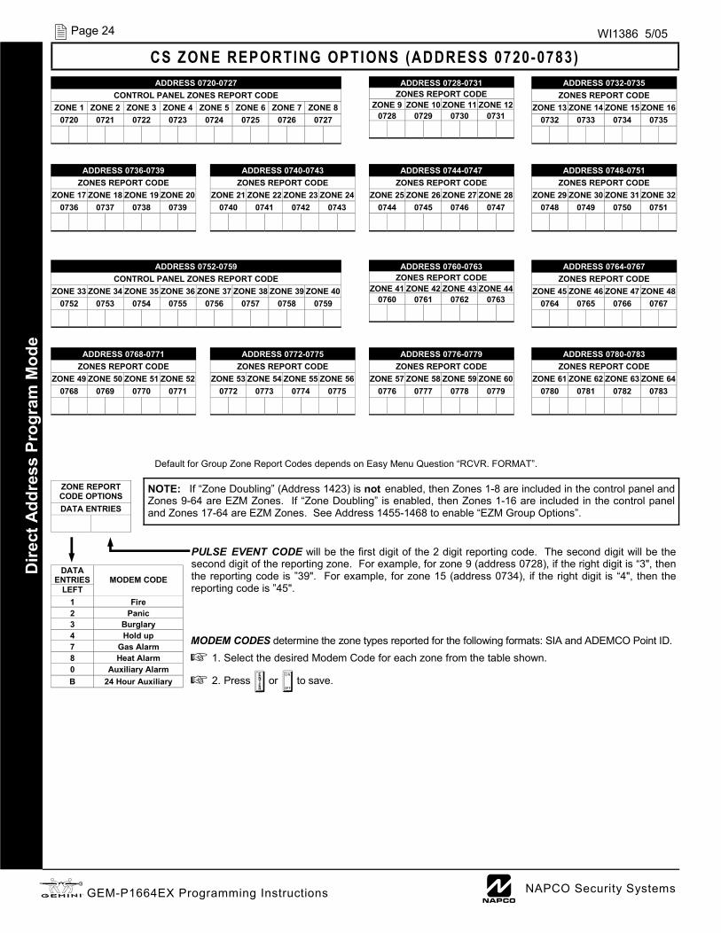
Default for Group Zone Report Codes depends on Easy Menu Question “RCVR. FORMAT”.
CS ZONE REPORTING OPTIONS (ADDRESS 0720-0783) ADDRESS 0720-0727
CONTROL PANEL ZONES REPORT CODE ZONE 1 ZONE 2 ZONE 3 ZONE 4 ZONE 5 ZONE 6 ZONE 7 ZONE 8
0720 0721 0722 0723 0724 0725 0726 0727
ADDRESS 0728-0731 ZONES REPORT CODE
ZONE 9 ZONE 10 ZONE 11 ZONE 12 0728 0729 0730 0731
ADDRESS 0732-0735 ZONES REPORT CODE
ZONE 13 ZONE 14 ZONE 15 ZONE 16 0732 0733 0734 0735
ADDRESS 0744-0747 ZONES REPORT CODE
ZONE 25 ZONE 26 ZONE 27 ZONE 28 0744 0745 0746 0747
ADDRESS 0748-0751 ZONES REPORT CODE
ZONE 29 ZONE 30 ZONE 31 ZONE 32 0748 0749 0750 0751
ADDRESS 0736-0739 ZONES REPORT CODE
ZONE 17 ZONE 18 ZONE 19 ZONE 20 0736 0737 0738 0739
ADDRESS 0740-0743 ZONES REPORT CODE
ZONE 21 ZONE 22 ZONE 23 ZONE 24 0740 0741 0742 0743
NOTE: If “Zone Doubling” (Address 1423) is not enabled, then Zones 1-8 are included in the control panel and Zones 9-64 are EZM Zones. If “Zone Doubling” is enabled, then Zones 1-16 are included in the control panel and Zones 17-64 are EZM Zones. See Address 1455-1468 to enable “EZM Group Options”.
PULSE EVENT CODE will be the first digit of the 2 digit reporting code. The second digit will be the second digit of the reporting zone. For example, for zone 9 (address 0728), if the right digit is “3", then the reporting code is ”39". For example, for zone 15 (address 0734), if the right digit is “4", then the reporting code is ”45".
MODEM CODES determine the zone types reported for the following formats: SIA and ADEMCO Point ID. 1. Select the desired Modem Code for each zone from the table shown.
2. Press U or D to save.
Dire
ct A
ddre
ss P
rogr
am M
ode
ZONE REPORT CODE OPTIONS DATA ENTRIES
DATA ENTRIES
MODEM CODE
LEFT 1 Fire 2 Panic 3 Burglary 4 Hold up 7 Gas Alarm 8 Heat Alarm 0 Auxiliary Alarm B 24 Hour Auxiliary
ADDRESS 0752-0759 CONTROL PANEL ZONES REPORT CODE
ZONE 33 ZONE 34 ZONE 35 ZONE 36 ZONE 37 ZONE 38 ZONE 39 ZONE 40 0752 0753 0754 0755 0756 0757 0758 0759
ADDRESS 0760-0763 ZONES REPORT CODE
ZONE 41 ZONE 42 ZONE 43 ZONE 44 0760 0761 0762 0763
ADDRESS 0764-0767 ZONES REPORT CODE
ZONE 45 ZONE 46 ZONE 47 ZONE 48 0764 0765 0766 0767
ADDRESS 0776-0779 ZONES REPORT CODE
ZONE 57 ZONE 58 ZONE 59 ZONE 60 0776 0777 0778 0779
ADDRESS 0780-0783 ZONES REPORT CODE
ZONE 61 ZONE 62 ZONE 63 ZONE 64 0780 0781 0782 0783
ADDRESS 0768-0771 ZONES REPORT CODE
ZONE 49 ZONE 50 ZONE 51 ZONE 52 0768 0769 0770 0771
ADDRESS 0772-0775 ZONES REPORT CODE
ZONE 53 ZONE 54 ZONE 55 ZONE 56 0772 0773 0774 0775

L NAPCO Security Systems X GEM-P1664EX Programming Instructions
Page 25 WI1386 5/05
CS USER REPORTING OPTIONS (ADDRESS 0800-0835) D
irect Address Program M
ode
USERS 1 8 USERS 9 16 ADDR U1 U2 U3 U4 U5 U6 U7 U8 ADDR U9 U10 U11 U12 U13 U14 U15 U16
1 2 3 4 5 6 7 8 1 2 3 4 5 6 7 8 Enable Opening Report, Telco 1 0800 0801
Enable Closing Report, Telco 1 0809 0810
Enable Opening Report, Telco 3 0818 0819
Enable Closing Report, Telco 3 0827 0828
Enable Users to Report Opening and Closings
USERS 17 24 USERS 25 32 ADDR U17 U18 U19 U20 U21 U22 U23 U24 ADDR U25 U26 U27 U28 U29 U30 U31 U32
1 2 3 4 5 6 7 8 1 2 3 4 5 6 7 8 Enable Opening Report, Telco 1 0802 0803
Enable Closing Report, Telco 1 0811 0812
Enable Opening Report, Telco 3 0820 0821
Enable Closing Report, Telco 3 0829 0830
Enable Users to Report Opening and Closings
CS USER REPORTING OPTIONS: [Default = blank (•) from address 0800-0835]
1. Select the desired option entering the option number (1-8) for each digit.
2. At the keypad, enter corresponding option number in address location. NOTE: Dark shaded data value box shows option not available.
3. Press U or D to save.
USERS 49 56 USERS 57 64 Enable Users to Report Opening
and Closings ADDR U49 U50 U51 U52 U53 U54 U55 U56 ADDR U57 U58 U59 U60 U61 U62 U63 U64
1 2 3 4 5 6 7 8 1 2 3 4 5 6 7 8 Enable Opening Report, Telco 1 0806 0807
Enable Closing Report, Telco 1 0815 0816
Enable Opening Report, Telco 3 0824 0825
Enable Closing Report, Telco 3 0833 0834
USERS 65 68 Enable Users to Report Opening
and Closings ADDR U65 U66 U67 U68
1 2 3 4 5 6 7 8 Enable Opening Report, Telco 1 0808
Enable Closing Report, Telco 1 0817
Enable Opening Report, Telco 3 0826
Enable Closing Report, Telco 3 0835
User 65 = Auto Arming/Disarming User 66 = Quickloader Remote Arming/Disarming User 67 = Easy Arming (Opening not applicable) User 68 = Keyswitch Arming NOTE: These opening events will report as the user number shown. Also, Keyfobs 1-8 (see Easy Menu Program Driven Mode) will report as Users 57-64, respectively.
USERS 33 40 USERS 41 48 Enable Users to Report Opening
and Closings ADDR U33 U34 U35 U36 U37 U38 U39 U40 ADDR U41 U42 U43 U44 U45 U46 U47 U48
1 2 3 4 5 6 7 8 1 2 3 4 5 6 7 8 Enable Opening Report, Telco 1 0804 0805
Enable Closing Report, Telco 1 0813 0814
Enable Opening Report, Telco 3 0822 0823
Enable Closing Report, Telco 3 0831 0832

X GEM-P1664EX Programming Instructions L NAPCO Security Systems
Page 26 WI1386 5/05
Default depends on Easy Menu Question “# OF ZNS IN AREA 1 ENTER # ZONES” and “EZ ZONE DOUBLING? Y/N”. For example, if 64 Zones are used and Zone Doubling is not enabled, then all 14 Groups will be automatically enabled. If 64 Zones are used and Zone Doubling is enabled, then only Groups 1-12 will be automatically enabled.
NOTE: If “Zone Doubling” (Address 1423, option 1) is not enabled, then Zones 1-8 are included in the control panel and Zones 9-64 (Groups 1-14) are EZM Zones. If “Zone Doubling” is enabled, then Zones 1-16 are included in the control panel and Zones 17-64 (Groups 1-12) are EZM Zones (and Groups 13 and 14 must not be used).
EZM GROUP OPTIONS: Up to 14 Groups of 4 Zones each may be pro-grammed depending on the number of Zones used and which EZM mod-ules are connected. Each Group represents 4 Zones.
1. Select EZM type from the table shown.
2. Enter either blank (•) or "1" in corresponding address locations above.
NOTE: Dark shaded data value box shows option not available. 3. Press U or D to save. D
irect
Add
ress
Pro
gram
Mod
e EZM GROUP OPTIONS (ADDRESS 1455-1468)
EZM Group 1 ADDRESS 1455
EZM Group 2 ADDRESS 1456
EZM Group 3 ADDRESS 1457
EZM Group 4 ADDRESS 1458
EZM Group 5 ADDRESS 1459
EZM Group 6 ADDRESS 1460
EZM TYPE DATA
ENTRIES
OPTION
blank (•) Not used (No EZM present)
1 4-Zone EZM
EZM Group 7 ADDRESS 1461
EZM Group 8 ADDRESS 1462
EZM Group 9 ADDRESS 1463
EZM Group 10 ADDRESS 1464
EZM Group 11 ADDRESS 1465
EZM Group 12 ADDRESS 1466
EZM Group 13 ADDRESS 1467
EZM Group 14 ADDRESS 1468
EZM GROUP NORMAL DOUBLED
1 9-12 17-20 2 13-16 21-24 3 17-20 25-28 4 21-24 29-32 5 25-28 33-36 6 29-32 37-40 7 33-36 41-44 8 37-40 45-48 9 41-44 49-52
10 45-48 53-56 11 49-52 57-60 12 53-56 61-64 13 57-60 14 61-64
ZONES COVERED

L NAPCO Security Systems X GEM-P1664EX Programming Instructions
Page 27 WI1386 5/05 D
irect Address Program M
ode
OUTPUT TURNS OFF UPON DISARM: Select options for any of the 4 Outputs. By default, the ability to turn off an output upon disarm is not allowed. For example, the ability to silence an Area 1 through Area 4 output via an Area 1 keypad is not enabled by default. To enable selected area output control, enter the number (1,2,3,4) accordingly. For example, if you wish to grant an Area 1 keypad the ability to turn off an Area 2 PGM2 output, enter "2" in Address 1485.
Enter digit in address location. NOTE: Dark shaded data value box shows option not available. Press U or D to save.
AREA BELL CONTROL OPTIONS (ADDRESS 1473-1488)
1481 PGM1 Output Turns Off upon Disarm Default Option: Disarming Area 1:
ON 1 Area 1 PGM1 Output Silenced OFF 2 Area 2 PGM1 Output Silenced OFF 3 Area 3 PGM1 Output Silenced OFF 4 Area 4 PGM1 Output Silenced
1482 PGM1 Output Turns Off upon Disarm Default Option: Disarming Area 2:
ON 1 Area 1 PGM1 Output Silenced OFF 2 Area 2 PGM1 Output Silenced OFF 3 Area 3 PGM1 Output Silenced OFF 4 Area 4 PGM1 Output Silenced
1485 PGM2 Output Turns Off upon Disarm Default Option: Disarming Area 1:
ON 1 Area 1 PGM2 Burg Output Silenced OFF 2 Area 2 PGM2 Burg Output Silenced OFF 3 Area 3 PGM2 Burg Output Silenced OFF 4 Area 4 PGM2 Burg Output Silenced
1486 PGM2 Output Turns Off upon Disarm Default Option: Disarming Area 2:
ON 1 Area 1 PGM2 Burg Output Silenced OFF 2 Area 2 PGM2 Burg Output Silenced OFF 3 Area 3 PGM2 Burg Output Silenced OFF 4 Area 4 PGM2 Burg Output Silenced
1473 Burglary Output Turns Off upon Disarm Default Option: Disarming Area 1:
ON 1 Area 1 Burg Output Silenced OFF 2 Area 2 Burg Output Silenced OFF 3 Area 3 Burg Output Silenced OFF 4 Area 4 Burg Output Silenced
1474 Burglary Output Turns Off upon Disarm Default Option: Disarming Area 2:
ON 1 Area 1 Burg Output Silenced OFF 2 Area 2 Burg Output Silenced OFF 3 Area 3 Burg Output Silenced OFF 4 Area 4 Burg Output Silenced
1477 Pulsed Burg Output Turns Off upon Disarm Default Option: Disarming Area 1:
ON 1 Area 1 Pulsed Burg Output Silenced OFF 2 Area 2 Pulsed Burg Output Silenced OFF 3 Area 3 Pulsed Burg Output Silenced OFF 4 Area 4 Pulsed Burg Output Silenced
1478 Pulsed Burg Output Turns Off upon Disarm Default Option: Disarming Area 2:
ON 1 Area 1 Pulsed Burg Output Silenced OFF 2 Area 2 Pulsed Burg Output Silenced OFF 3 Area 3 Pulsed Burg Output Silenced OFF 4 Area 4 Pulsed Burg Output Silenced
1475 Burglary Output Turns Off upon Disarm Default Option: Disarming Area 3:
ON 1 Area 1 Burg Output Silenced OFF 2 Area 2 Burg Output Silenced OFF 3 Area 3 Burg Output Silenced OFF 4 Area 4 Burg Output Silenced
1476 Burglary Output Turns Off upon Disarm Default Option: Disarming Area 4:
ON 1 Area 1 Burg Output Silenced OFF 2 Area 2 Burg Output Silenced OFF 3 Area 3 Burg Output Silenced OFF 4 Area 4 Burg Output Silenced
1479 Pulsed Burg Output Turns Off upon Disarm Default Option: Disarming Area 3:
ON 1 Area 1 Pulsed Burg Output Silenced OFF 2 Area 2 Pulsed Burg Output Silenced OFF 3 Area 3 Pulsed Burg Output Silenced OFF 4 Area 4 Pulsed Burg Output Silenced
1480 Pulsed Burg Output Turns Off upon Disarm Default Option: Disarming Area 4:
ON 1 Area 1 Pulsed Burg Output Silenced OFF 2 Area 2 Pulsed Burg Output Silenced OFF 3 Area 3 Pulsed Burg Output Silenced OFF 4 Area 4 Pulsed Burg Output Silenced
1483 PGM1 Output Turns Off upon Disarm Default Option: Disarming Area 3:
ON 1 Area 1 PGM1 Output Silenced OFF 2 Area 2 PGM1 Output Silenced OFF 3 Area 3 PGM1 Output Silenced OFF 4 Area 4 PGM1 Output Silenced
1484 PGM1 Output Turns Off upon Disarm Default Option: Disarming Area 4:
ON 1 Area 1 PGM1 Output Silenced OFF 2 Area 2 PGM1 Output Silenced OFF 3 Area 3 PGM1 Output Silenced OFF 4 Area 4 PGM1 Output Silenced
1487 PGM2 Output Turns Off upon Disarm Default Option: Disarming Area 3:
ON 1 Area 1 PGM2 Burg Output Silenced OFF 2 Area 2 PGM2 Burg Output Silenced OFF 3 Area 3 PGM2 Burg Output Silenced OFF 4 Area 4 PGM2 Burg Output Silenced
1488 PGM2 Output Turns Off upon Disarm Default Option: Disarming Area 4:
ON 1 Area 1 PGM2 Burg Output Silenced OFF 2 Area 2 PGM2 Burg Output Silenced OFF 3 Area 3 PGM2 Burg Output Silenced OFF 4 Area 4 PGM2 Burg Output Silenced

X GEM-P1664EX Programming Instructions L NAPCO Security Systems
Page 28 WI1386 5/05
Enable Keypad Options
Enable Keypad Options ADDR Keypad
Fire Keypad
Aux. Keypad Panic RSRVD Ambush
Easy Arming
Panel Access RSRVD
1 2 3 4 5 6 7 8
Keypad 1 Options 1440
Keypad 2 Options 1441
Keypad 3 Options 1442
Keypad 4 Options 1443 Keypad 5 Options 1444 Keypad 6 Options 1445 Keypad 7 Options 1446
[Default = blank (•) from address 1440-1446]
KEYPAD OPTIONS (ADDRESS 0723-0736 & 1055-1058) D
irect
Add
ress
Pro
gram
Mod
e KEYPAD OPTIONS (ADDRESS 1425-1431, 1440-1446)
Enable Keypad Type & Activation
Enable Keypad Type Keypad Area Assignment KEYPAD TYPE: Up to 7 key-pads may be programmed, if they are connected.
NOTE: See Keypad Configura-tion Mode. 1. Select keypad type for each
keypad from the tables shown.
2. Enter data in corresponding address locations.
3. Press U or D to save.
ADDR
Blank (•) = Burg Keypad 2 = Wizard
Blank (•) = Disabled 1 = Area 1 2 = Area 2 3 = Area 3 4 = Area 4
Keypad 1 1425 Keypad 2 1426 Keypad 3 1427 Keypad 4 1428 Keypad 5 1429 Keypad 6 1430 Keypad 7 1431
[Default = blank (•) from address 1425-1431
ENABLE KEYPAD OPTIONS: Select options for any of the 7 keypads. 1. Select the desired option entering the option number (1-8) for each digit.
2. At the keypad, enter corresponding option number in address location. NOTE: Dark shaded data value box shows option not available.
3. Press U or D to save.

L NAPCO Security Systems X GEM-P1664EX Programming Instructions
Page 29 WI1386 5/05 D
irect Address Program M
ode TEMPERATURE DISPLAY AT KEYPAD (ADDRESS 1666-1668)
Temperature Display at the Keypad The temperature is displayed instead of the date on line 2 of the GEM-RP1CAe2 keypad. The keypad will display from –22F to 140F (or -30C to 60C). Fahrenheit is the default setting, select Celsius by enabling address 1668 option 2. When this Tempera-ture Display Option is enabled, Zone 6 becomes the input for the “Napco Temperature Sensor” module and Zone 6 of the panel becomes inoperative; if Zone Doubling is selected, zones 6, 14 will be inoperative. Address 1668 option 3 enables Zone 6 to report a temperature problem. Address 1666 (options 1-7) set the lower limit tempera-ture value and address 1667 (options 1-7) sets the upper limit temperature value (both values are set in binary). If the temperature detected by the panel is above or below these set limits, the panel will report an alarm on Zone 6. To function and report properly, Zone 6 must be selected as a reporting zone, 24hr zone in area 1 and auto-resetable. At both 1666 and 1667 addresses, option 8 sets positive or negative temperature. If the temperature of 0 degrees is required, "negative zero" (-0) degrees must be used (+0 or an empty location is not a valid temperature). To simulate the sensor module, a power supply can be connected to Zone 6 and set from .55v to 3.05v to display the whole temperature range. Temperature values are read and updated every 5 seconds. To report an outer limit temperature, the temperature must be out of limits for 2 seconds. To avoid false alarm reports, the limits have a threshold of 5 degrees in the software. Two new logs have been created for temperature out of limits and restore. If the G key is depressed and held down for 2 seconds, the date will display for 5 seconds.
1668 Default Option
OFF 1 Enable Temperature Display Option OFF 2 Select Degrees Celsius OFF 3 Report Temperature Alarm (Zone 6) OFF 4 Reserved OFF 5 Reserved OFF 6 Reserved OFF 7 Reserved OFF 8 Reserved
Enable Temperature Options
1666 Default Option
OFF 1 Binary Temperature Value 1° OFF 2 Binary Temperature Value 2° OFF 3 Binary Temperature Value 4° OFF 4 Binary Temperature Value 8° OFF 5 Binary Temperature Value 16° OFF 6 Binary Temperature Value 32° OFF 7 Binary Temperature Value 64° OFF 8 Enable for Negative Temperature Value
Temperature Lower Limit 1667 Default Option
OFF 1 Binary Temperature Value 1° OFF 2 Binary Temperature Value 2° OFF 3 Binary Temperature Value 4° OFF 4 Binary Temperature Value 8° OFF 5 Binary Temperature Value 16° OFF 6 Binary Temperature Value 32° OFF 7 Binary Temperature Value 64° OFF 8 Enable for Negative Temperature Value
Temperature Upper Limit
- -ZONE 6 TEMPERATURE SENSOR--

X GEM-P1664EX Programming Instructions L NAPCO Security Systems
Page 30 WI1386 5/05 D
irect
Add
ress
Pro
gram
Mod
e
AREA ARMING OPTIONS (ADDRESS 1469-1472)
PRIORITY AREA ARMING: 1. Select option from the table shown.
2. Enter either blank (•) or "1" in corresponding address location. NOTE: Dark shaded data value box shows option not available.
3. Press U or D to save.
PRIORITY ARMING/AREA 1 DATA ENTRIES OPTION
blank (•) Not Used Enabled 1
PRIORITY ARMING/AREA 2 DATA ENTRIES OPTION
blank (•) Not Used Enabled 1
Priority Arming Area 1
ADDRESS 1469
[Default = blank (•)]
Priority Arming Area 2
ADDRESS 1470
[Default = blank (•)]
ZONE INTEGRATION TIME (ADDRESS 2062) Zone Integration Time: The panel Zone Integration (Response) time can be adjusted to a new global value. Address 2062 accepts three decimal digits which are multiplied by 10 milli-seconds to get a new value that replaces the default value of 750ms. If the loca-tion is set to 000, the system will default to 750ms internally. The maximum value is 255. If a value above 255 is entered the system will display 000 to request a re-entry.
Note: Only the panel zones’ integration times are programmable. EZM’s will continue to use either 50 or 750 ms as selected by jumpers on the EZM. In addition, zone responses are enabled only when armed.
1. Enter digit only.
2. Valid entries are: 001-750. NOTE: Default is 750ms (075 x 10ms).
3. Press U or D to save.
ADDRESS 2062
[Default = 075 x 10ms]
Zone Integration
Time (x 10ms)
PRIORITY ARMING/AREA 3 DATA ENTRIES OPTION
blank (•) Not Used Enabled 1
PRIORITY ARMING/AREA 4 DATA ENTRIES OPTION
blank (•) Not Used Enabled 1
Priority Arming Area 3
ADDRESS 1471
[Default = blank (•)]
Priority Arming Area 4
ADDRESS 1472
[Default = blank (•)]
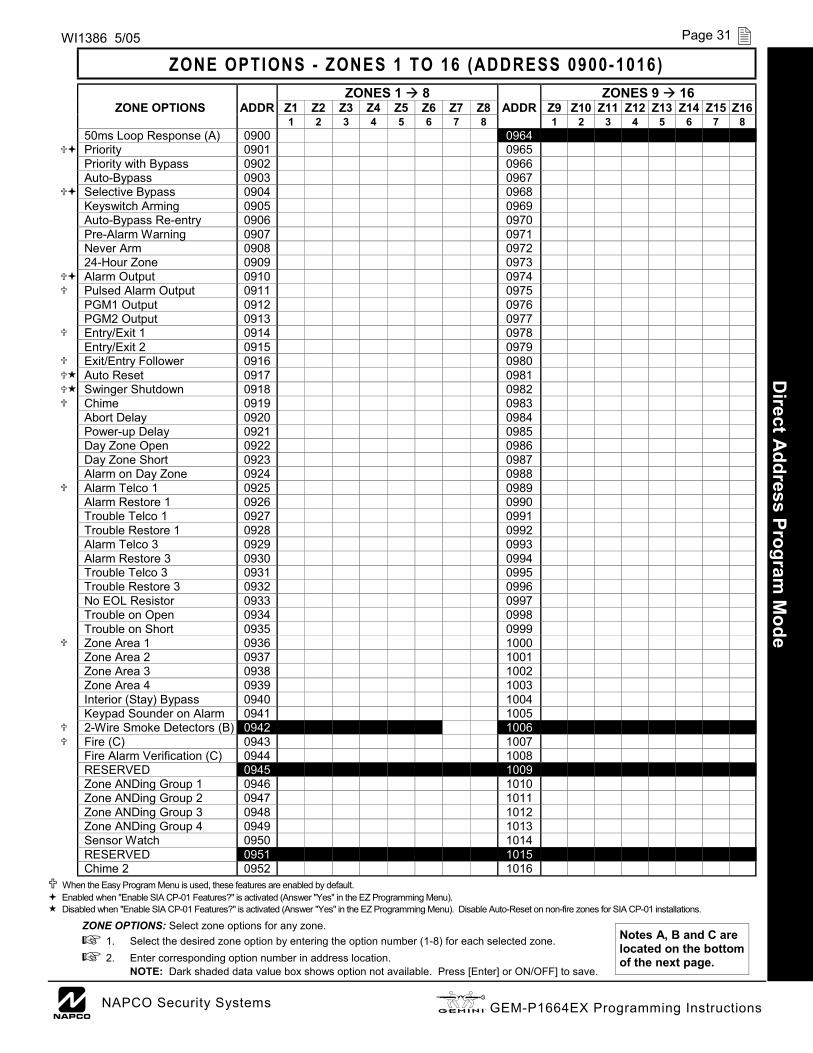
L NAPCO Security Systems X GEM-P1664EX Programming Instructions
Page 31 WI1386 5/05
ZONE OPTIONS - ZONES 1 TO 16 (ADDRESS 0900-1016) D
irect Address Program M
ode
ZONES 1 8 ZONES 9 16 ZONE OPTIONS ADDR Z1 Z2 Z3 Z4 Z5 Z6 Z7 Z8 ADDR Z9 Z10 Z11 Z12 Z13 Z14 Z15 Z16
1 2 3 4 5 6 7 8 1 2 3 4 5 6 7 8 50ms Loop Response (A) 0900 0964 Priority 0901 0965 Priority with Bypass 0902 0966 Auto-Bypass 0903 0967 Selective Bypass 0904 0968 Keyswitch Arming 0905 0969 Auto-Bypass Re-entry 0906 0970 Pre-Alarm Warning 0907 0971 Never Arm 0908 0972 24-Hour Zone 0909 0973 Alarm Output 0910 0974
Pulsed Alarm Output 0911 0975 PGM1 Output 0912 0976 PGM2 Output 0913 0977
Entry/Exit 1 0914 0978 Entry/Exit 2 0915 0979
Exit/Entry Follower 0916 0980 Auto Reset 0917 0981 Swinger Shutdown 0918 0982
Chime 0919 0983 Abort Delay 0920 0984 Power-up Delay 0921 0985 Day Zone Open 0922 0986 Day Zone Short 0923 0987 Alarm on Day Zone 0924 0988
Alarm Telco 1 0925 0989 Alarm Restore 1 0926 0990 Trouble Telco 1 0927 0991 Trouble Restore 1 0928 0992 Alarm Telco 3 0929 0993 Alarm Restore 3 0930 0994 Trouble Telco 3 0931 0995 Trouble Restore 3 0932 0996 No EOL Resistor 0933 0997 Trouble on Open 0934 0998 Trouble on Short 0935 0999
Zone Area 1 0936 1000 Zone Area 2 0937 1001
Zone Area 3 0938 1002
Keypad Sounder on Alarm 0941 1005 2-Wire Smoke Detectors (B) 0942 1006 Fire (C) 0943 1007 Fire Alarm Verification (C) 0944 1008 RESERVED 0945 1009 Zone ANDing Group 1 0946 1010 Zone ANDing Group 2 0947 1011 Zone ANDing Group 3 0948 1012 Zone ANDing Group 4 0949 1013 Sensor Watch 0950 1014 RESERVED 0951 1015 Chime 2 0952 1016
When the Easy Program Menu is used, these features are enabled by default. Enabled when "Enable SIA CP-01 Features?" is activated (Answer "Yes" in the EZ Programming Menu). Disabled when "Enable SIA CP-01 Features?" is activated (Answer "Yes" in the EZ Programming Menu). Disable Auto-Reset on non-fire zones for SIA CP-01 installations.
Interior (Stay) Bypass 0940 1004 Zone Area 4 0939 1003
ZONE OPTIONS: Select zone options for any zone. 1. Select the desired zone option by entering the option number (1-8) for each selected zone. 2. Enter corresponding option number in address location.
NOTE: Dark shaded data value box shows option not available. Press [Enter] or ON/OFF] to save.
Notes A, B and C are located on the bottom of the next page.

X GEM-P1664EX Programming Instructions L NAPCO Security Systems
Page 32 WI1386 5/05
ZONE OPTIONS - ZONES 17 TO 32 (ADDRESS 1029-1144) D
irect
Add
ress
Pro
gram
Mod
e
ZONES 17 → 24 ZONES 25 → 32 ZONE FEATURES ADDR Z17 Z18 Z19 Z20 Z21 Z22 Z23 Z24 ADDR Z25 Z26 Z27 Z28 Z29 Z30 Z31 Z32 1 2 3 4 5 6 7 8 1 2 3 4 5 6 7 8 Priority 1029 1093 Priority with Bypass 1030 1094 Auto-Bypass 1031 1095 Selective Bypass 1032 1096 Keyswitch Arming 1033 1097 Auto-Bypass Re-entry 1034 1098 Pre-Alarm Warning 1035 1099 Never Arm 1036 1100 24-Hour Zone 1037 1101 Alarm Output 1038 1102 Pulsed Alarm Output 1039 1103 PGM1 Output 1040 1104 PGM2 Output 1041 1105 Entry/Exit 1 1042 1106 Entry/Exit 2 1043 1107 Exit/Entry Follower 1044 1108 Auto Reset 1045 1109 Swinger Shutdown 1046 1110 Chime 1047 1111 Abort Delay 1048 1112 Power-up Delay 1049 1113 Day Zone Open 1050 1114 Day Zone Short 1051 1115 Alarm on Day Zone 1052 1116 Alarm Telco 1 1053 1117 Alarm Restore 1 1054 1118 Trouble Telco 1 1055 1119 Trouble Restore 1 1056 1120 Alarm Telco 3 1057 1121 Alarm Restore 3 1058 1122 Trouble Telco 3 1059 1123 Trouble Restore 3 1060 1124 No EOL Resistor 1061 1125 Trouble on Open 1062 1126 Trouble on Short 1063 1127 Zone Area 1 1064 1128 Zone Area 2 1065 1129
Interior (Stay) Bypass 1068 1132 Keypad Sounder on Alarm 1069 1133 Fire (C) 1071 1135 Fire Alarm Verification (C) 1072 1136 Zone ANDing Group 1 1074 1138 Zone ANDing Group 2 1075 1139 Zone ANDing Group 3 1076 1140 Zone ANDing Group 4 1077 1141 Sensor Watch 1078 1142 RESERVED 1079 1143 Chime 2 1080 1144
When the Easy Program Menu is used, these features are enabled by default. Enabled when "Enable SIA CP-01 Features?" is activated (Answer "Yes" in the EZ Programming Menu). Disabled when "Enable SIA CP-01 Features?" is activated (Answer "Yes" in the EZ Programming Menu). Disable Auto-Reset on non-fire zones for SIA CP-01 installations.
Zone Area 3 1066 1130 Zone Area 4 1067 1131
NOTES: (A) 50ms Loop Response only available for zones 1-8. If Zone Doubling is enabled, Zones 9-16 will follow the loop response programming for Zones 1-8. For all other Zones, loop response is determined by jumpers on the GEM-EZM8 and/or keypad configuration on the GEM-RP1CAe2 or GEM-K1CA.
(B) 2-wire Smoke Detectors only available for zones 7 & 8, and Fire must also be selected. (C) If Fire Alarm Verification is selected, then Fire must also be selected. DEFAULTS: The zone options indicated are automatically set after exiting the Easy Menu Driven Mode.
• Priority, Selective Bypass, Alarm Output, Auto Reset, Swinger Shutdown and Zone Area 1 are enabled for the total number of zones entered in “# OF ZONES IN AREA1 ENTER # ZONES”. • Alarm Telco 1 is enabled for the zone number(s) entered in “REPORT ALL ZONES TO CENTRAL ZONES? Y/N”. • Entry/Exit 1 and Chime are enabled for the zone number(s) entered in “ENTRY/EXIT ZONES ENTER ZONE #”. • Exit/Entry Follower and Interior Bypass are enabled for the zone number(s) entered in “INTERIOR ZONES ENTER ZONE #”. • Pulse Alarm Output is enabled for the zone number(s) entered in “FIRE ZONES ENTER ZONE #” or “2-WIRE FIRE ZNS ENTER ZONE #”. • Fire is enabled for the zone number(s) entered in “FIRE ZONES ENTER ZONE #”. • 2-Wire Smoke Detector is enabled for the zone number(s) entered in “2-WIRE FIRE ZNS ENTER ZONE #”.

L NAPCO Security Systems X GEM-P1664EX Programming Instructions
Page 33 WI1386 5/05
ZONE OPTIONS - ZONES 33 TO 48 (ADDRESS 1157-1272) D
irect Address Program M
ode
ZONES 33 40 ZONES 41 48 ZONE OPTIONS ADDR Z33 Z34 Z35 Z36 Z37 Z38 Z39 Z40 ADDR Z41 Z42 Z43 Z44 Z45 Z46 Z47 Z48
1 2 3 4 5 6 7 8 1 2 3 4 5 6 7 8 50ms Loop Response (A) Priority 1157 1221 Priority with Bypass 1158 1222 Auto-Bypass 1159 1223 Selective Bypass 1160 1224 Keyswitch Arming 1161 1225 Auto-Bypass Re-entry 1162 1226 Pre-Alarm Warning 1163 1227 Never Arm 1164 1228 24-Hour Zone 1165 1229 Alarm Output 1166 1230
Pulsed Alarm Output 1167 1231 PGM1 Output 1168 1232 PGM2 Output 1169 1233
Entry/Exit 1 1170 1234 Entry/Exit 2 1171 1235
Exit/Entry Follower 1172 1236 Auto Reset 1173 1237 Swinger Shutdown 1174 1238
Chime 1175 1239 Abort Delay 1176 1240 Power-up Delay 1177 1241 Day Zone Open 1178 1242 Day Zone Short 1179 1243 Alarm on Day Zone 1180 1244
Alarm Telco 1 1181 1245 Alarm Restore 1 1182 1246 Trouble Telco 1 1183 1247 Trouble Restore 1 1184 1248 Alarm Telco 3 1185 1249 Alarm Restore 3 1186 1250 Trouble Telco 3 1187 1251 Trouble Restore 3 1188 1252 No EOL Resistor 1189 1253 Trouble on Open 1190 1254 Trouble on Short 1191 1255
Zone Area 1 1192 1256 Zone Area 2 1193 1257
Interior (Stay) Bypass 1196 1260 Keypad Sounder on Alarm 1197 1261
2-Wire Smoke Detectors (B) 1198 1262 Fire (C) 1199 1263 Fire Alarm Verification (C) 1200 1264 RESERVED 1201 1265 Zone ANDing Group 1 1202 1266 Zone ANDing Group 2 1203 1267 Zone ANDing Group 3 1204 1268 Zone ANDing Group 4 1205 1269 Sensor Watch 1206 1270 RESERVED 1207 1271 Chime 2 1208 1272
When the Easy Program Menu is used, these features are enabled by default. Enabled when "Enable SIA CP-01 Features?" is activated (Answer "Yes" in the EZ Programming Menu). Disabled when "Enable SIA CP-01 Features?" is activated (Answer "Yes" in the EZ Programming Menu). Disable Auto-Reset on non-fire zones for SIA CP-01 installations.
Zone Area 3 1194 1258 Zone Area 4 1195 1259
ZONE OPTIONS: Select zone options for any zone. 1. Select the desired zone option by entering the option number (1-8) for each selected zone. 2. Enter corresponding option number in address location.
NOTE: Dark shaded data value box shows option not available. Press [Enter] or ON/OFF] to save.

X GEM-P1664EX Programming Instructions L NAPCO Security Systems
Page 34 WI1386 5/05
ZONE OPTIONS - ZONES 49 TO 64 (ADDRESS 1285-1400) D
irect
Add
ress
Pro
gram
Mod
e
ZONES 49 → 56 ZONES 57 → 64 ZONE FEATURES ADDR Z49 Z50 Z51 Z52 Z53 Z54 Z55 Z56 ADDR Z57 Z58 Z59 Z60 Z61 Z62 Z63 Z64 1 2 3 4 5 6 7 8 1 2 3 4 5 6 7 8 Priority 1285 1349 Priority with Bypass 1286 1350 Auto-Bypass 1287 1351 Selective Bypass 1288 1352 Keyswitch Arming 1289 1353 Auto-Bypass Re-entry 1290 1354 Pre-Alarm Warning 1291 1355 Never Arm 1292 1356 24-Hour Zone 1293 1357 Alarm Output 1294 1358 Pulsed Alarm Output 1295 1359 PGM1 Output 1296 1360 PGM2 Output 1297 1361 Entry/Exit 1 1298 1362 Entry/Exit 2 1299 1363 Exit/Entry Follower 1300 1364 Auto Reset 1301 1365 Swinger Shutdown 1302 1366 Chime 1303 1367 Abort Delay 1304 1368 Power-up Delay 1305 1369 Day Zone Open 1306 1370 Day Zone Short 1307 1371 Alarm on Day Zone 1308 1372 Alarm Telco 1 1309 1373 Alarm Restore 1 1310 1374 Trouble Telco 1 1311 1375 Trouble Restore 1 1312 1376 Alarm Telco 3 1313 1377 Alarm Restore 3 1314 1378 Trouble Telco 3 1315 1379 Trouble Restore 3 1316 1380 No EOL Resistor 1317 1381 Trouble on Open 1318 1382 Trouble on Short 1319 1383 Zone Area 1 1320 1384 Zone Area 2 1321 1385
Interior (Stay) Bypass 1324 1388 Keypad Sounder on Alarm 1325 1389 Fire (C) 1327 1391 Fire Alarm Verification (C) 1328 1392 Zone ANDing Group 1 1330 1394 Zone ANDing Group 2 1331 1395 Zone ANDing Group 3 1332 1396 Zone ANDing Group 4 1333 1397 Sensor Watch 1334 1398 RESERVED 1335 1399 Chime 2 1336 1400
When the Easy Program Menu is used, these features are enabled by default. Enabled when "Enable SIA CP-01 Features?" is activated (Answer "Yes" in the EZ Programming Menu). Disabled when "Enable SIA CP-01 Features?" is activated (Answer "Yes" in the EZ Programming Menu). Disable Auto-Reset on non-fire zones for SIA CP-01 installations.
Zone Area 3 1322 1386 Zone Area 4 1323 1387
NOTES: (A) 50ms Loop Response only available for zones 1-8. If Zone Doubling is enabled, Zones 9-16 will follow the loop response programming for Zones 1-8. For all other Zones, loop response is determined by jumpers on the GEM-EZM8 and/or keypad configuration on the GEM-RP1CAe2 or GEM-K1CA.
(B) 2-wire Smoke Detectors only available for zones 7 & 8, and Fire must also be selected. (C) If Fire Alarm Verification is selected, then Fire must also be selected. DEFAULTS: The zone options indicated are automatically set after exiting the Easy Menu Driven Mode.
Priority, Selective Bypass, Alarm Output, Auto Reset, Swinger Shutdown and Zone Area 1 are enabled for the total number of zones entered in “# OF ZONES IN AREA1 ENTER # ZONES”. Alarm Telco 1 is enabled for the zone number(s) entered in “REPORT ALL ZONES TO CENTRAL ZONES? Y/N”. Entry/Exit 1 and Chime are enabled for the zone number(s) entered in “ENTRY/EXIT ZONES ENTER ZONE #”. Exit/Entry Follower and Interior Bypass are enabled for the zone number(s) entered in “INTERIOR ZONES ENTER ZONE #”. Pulse Alarm Output is enabled for the zone number(s) entered in “FIRE ZONES ENTER ZONE #” or “2-WIRE FIRE ZNS ENTER ZONE #”. Fire is enabled for the zone number(s) entered in “FIRE ZONES ENTER ZONE #”. 2-Wire Smoke Detector is enabled for the zone number(s) entered in “2-WIRE FIRE ZNS ENTER ZONE #”.

L NAPCO Security Systems X GEM-P1664EX Programming Instructions
Page 35 WI1386 5/05
EXTERNAL RELAY CONTROL (ADDRESS 1489-1648) ADDRESS 1489-1493 (RELAY EVENT 1)
1489 1490 1491 1492 1493 RELAY # AREA TIMEOUT EVENT ID COND.
Direct Address Program
Mode
[Default = blank (•) from address 1489-1648].
ADDRESS 1494-1498 (RELAY EVENT 2) 1494 1495 1496 1497 1498
RELAY # AREA TIMEOUT EVENT ID COND.
ADDRESS 1499-1503 (RELAY EVENT 3) 1499 1500 1501 1502 1503
RELAY # AREA TIMEOUT EVENT ID COND.
ADDRESS 1564-1568 (RELAY EVENT 16) 1564 1565 1566 1567 1568
RELAY # AREA TIMEOUT EVENT ID COND.
ADDRESS 1504-1508 (RELAY EVENT 4) 1504 1505 1506 1507 1508
RELAY # AREA TIMEOUT EVENT ID COND.
ADDRESS 1509-1513 (RELAY EVENT 5) 1509 1510 1511 1512 1513
RELAY # AREA TIMEOUT EVENT ID COND.
ADDRESS 1514-1518 (RELAY EVENT 6) 1514 1515 1516 1517 1518
RELAY # AREA TIMEOUT EVENT ID COND.
ADDRESS 1549-1553 (RELAY EVENT 13) 1549 1550 1551 1552 1553
RELAY # AREA TIMEOUT EVENT ID COND.
ADDRESS 1544-1548 (RELAY EVENT 12) 1544 1545 1546 1547 1548
RELAY # AREA TIMEOUT EVENT ID COND.
ADDRESS 1539-1543 (RELAY EVENT 11) 1539 1540 1541 1542 1543
RELAY # AREA TIMEOUT EVENT ID COND.
ADDRESS 1534-1538 (RELAY EVENT 10) 1534 1535 1536 1537 1538
RELAY # AREA TIMEOUT EVENT ID COND.
ADDRESS 1529-1533 (RELAY EVENT 9) 1529 1530 1531 1532 1533
RELAY # AREA TIMEOUT EVENT ID COND.
ADDRESS 1524-1528 (RELAY EVENT 8) 1524 1525 1526 1527 1528
RELAY # AREA TIMEOUT EVENT ID COND.
ADDRESS 1519-1523 (RELAY EVENT 7) 1519 1520 1521 1522 1523
RELAY # AREA TIMEOUT EVENT ID COND.
ADDRESS 1559-1563 (RELAY EVENT 15) 1559 1560 1561 1562 1563
RELAY # AREA TIMEOUT EVENT ID COND.
ADDRESS 1554-1558 (RELAY EVENT 14) 1554 1555 1556 1557 1558
RELAY # AREA TIMEOUT EVENT ID COND.
ADDRESS 1574-1578 (RELAY EVENT 18) 1574 1575 1576 1577 1578
RELAY # AREA TIMEOUT EVENT ID COND.
ADDRESS 1569-1573 (RELAY EVENT 17) 1569 1570 1571 1572 1573
RELAY # AREA TIMEOUT EVENT ID COND.
ADDRESS 1579-1583 (RELAY EVENT 19) 1579 1580 1581 1582 1583
RELAY # AREA TIMEOUT EVENT ID COND.
ADDRESS 1589-1593 (RELAY EVENT 21) 1589 1590 1591 1592 1593
RELAY # AREA TIMEOUT EVENT ID COND.
ADDRESS 1584-1588 (RELAY EVENT 20) 1584 1585 1586 1587 1588
RELAY # AREA TIMEOUT EVENT ID COND.
ADDRESS 1594-1598 (RELAY EVENT 22) 1594 1595 1596 1597 1598
RELAY # AREA TIMEOUT EVENT ID COND.
ADDRESS 1604-1608 (RELAY EVENT 24) 1604 1605 1606 1607 1608
RELAY # AREA TIMEOUT EVENT ID COND.
ADDRESS 1599-1603 (RELAY EVENT 23) 1599 1600 1601 1602 1603
RELAY # AREA TIMEOUT EVENT ID COND.
ADDRESS 1609-1613 (RELAY EVENT 25) 1609 1610 1611 1612 1613
RELAY # AREA TIMEOUT EVENT ID COND.
ADDRESS 1619-1623 (RELAY EVENT 27) 1619 1620 1621 1622 1623
RELAY # AREA TIMEOUT EVENT ID COND.
ADDRESS 1614-1618 (RELAY EVENT 26) 1614 1615 1616 1617 1618
RELAY # AREA TIMEOUT EVENT ID COND.
ADDRESS 1624-1628 (RELAY EVENT 28) 1624 1625 1626 1627 1628
RELAY # AREA TIMEOUT EVENT ID COND.
ADDRESS 1634-1638 (RELAY EVENT 30) 1634 1635 1636 1637 1638
RELAY # AREA TIMEOUT EVENT ID COND.
ADDRESS 1629-1633 (RELAY EVENT 29) 1629 1630 1631 1632 1633
RELAY # AREA TIMEOUT EVENT ID COND.
ADDRESS 1639-1643 (RELAY EVENT 31) 1639 1640 1641 1642 1643
RELAY # AREA TIMEOUT EVENT ID COND.
ADDRESS 1644-1648 (RELAY EVENT 32) 1644 1645 1646 1647 1648
RELAY # AREA TIMEOUT EVENT ID COND. TO PROGRAM,
SEE NEXT PAGE
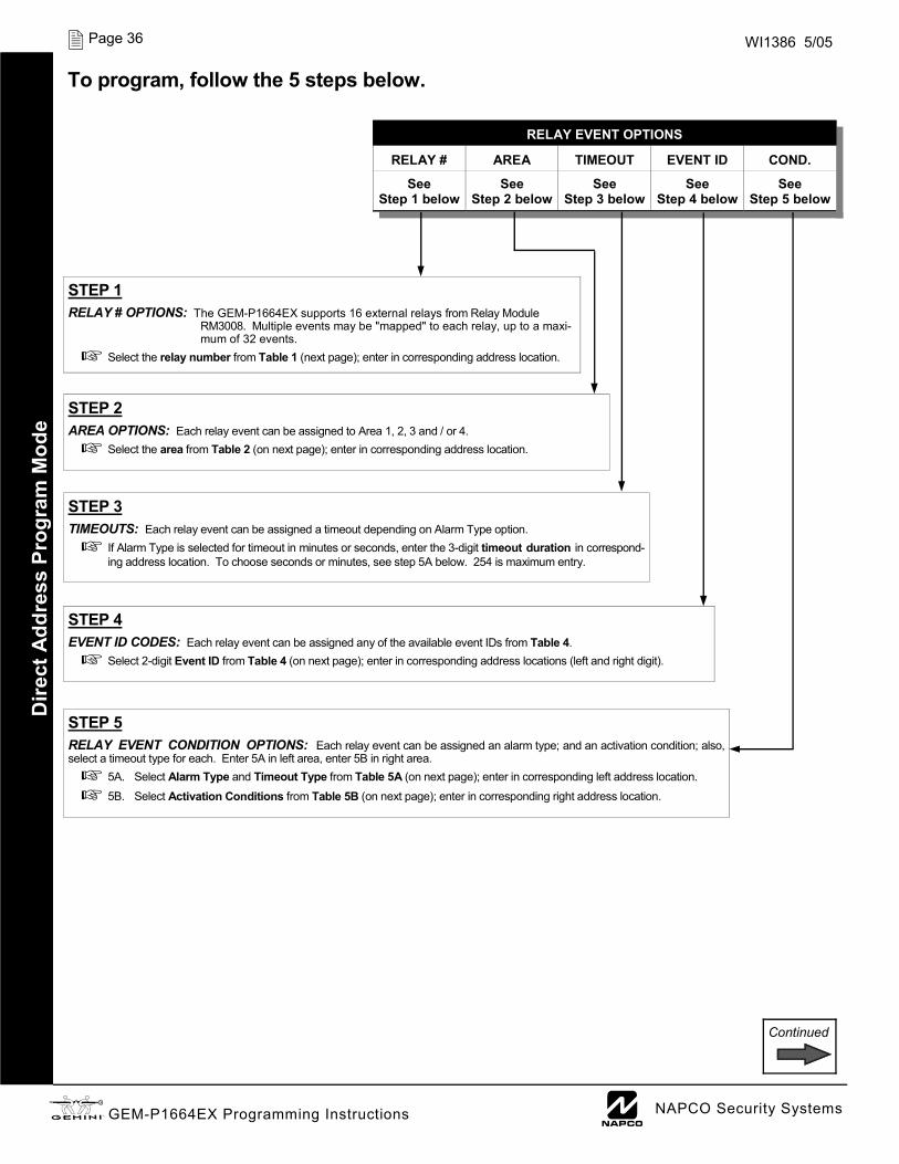
X GEM-P1664EX Programming Instructions L NAPCO Security Systems
Page 36 WI1386 5/05
Continued
RELAY EVENT OPTIONS
RELAY # AREA TIMEOUT EVENT ID COND.
See Step 1 below
See Step 2 below
See Step 3 below
See Step 4 below
See Step 5 below
To program, follow the 5 steps below.
STEP 4
EVENT ID CODES: Each relay event can be assigned any of the available event IDs from Table 4. Select 2-digit Event ID from Table 4 (on next page); enter in corresponding address locations (left and right digit).
STEP 5
RELAY EVENT CONDITION OPTIONS: Each relay event can be assigned an alarm type; and an activation condition; also, select a timeout type for each. Enter 5A in left area, enter 5B in right area.
5A. Select Alarm Type and Timeout Type from Table 5A (on next page); enter in corresponding left address location. 5B. Select Activation Conditions from Table 5B (on next page); enter in corresponding right address location.
STEP 2
AREA OPTIONS: Each relay event can be assigned to Area 1, 2, 3 and / or 4. Select the area from Table 2 (on next page); enter in corresponding address location.
STEP 1
RELAY # OPTIONS: The GEM-P1664EX supports 16 external relays from Relay Module RM3008. Multiple events may be "mapped" to each relay, up to a maxi-mum of 32 events.
Select the relay number from Table 1 (next page); enter in corresponding address location.
STEP 3
TIMEOUTS: Each relay event can be assigned a timeout depending on Alarm Type option. If Alarm Type is selected for timeout in minutes or seconds, enter the 3-digit timeout duration in correspond-ing address location. To choose seconds or minutes, see step 5A below. 254 is maximum entry.
Dire
ct A
ddre
ss P
rogr
am M
ode
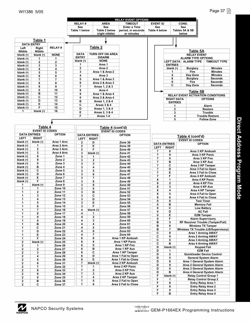
L NAPCO Security Systems X GEM-P1664EX Programming Instructions
Page 37 WI1386 5/05
Table 4 (cont'd) EVENT ID CODES
DATA ENTRIES OPTION LEFT RIGHT
2 D Zone 38 2 E Zone 39 2 F Zone 40 3 blank (•) Zone 41 3 1 Zone 42 3 2 Zone 43 3 3 Zone 44 3 4 Zone 45 3 5 Zone 46 3 6 Zone 47 3 7 Zone 48 3 8 Zone 49 3 9 Zone 50 3 0 Zone 51 3 B Zone 52 3 C Zone 53 3 D Zone 54 3 E Zone 55 3 F Zone 56 4 blank (•) Zone 57 4 1 Zone 58 4 2 Zone 59 4 3 Zone 60 4 4 Zone 61 4 5 Zone 62 4 6 Zone 63 4 7 Zone 64 6 8 Area 1 KP Ambush 6 9 Area 1 KP Panic 6 0 Area 1 KP Fire 6 B Area 1 KP Aux 6 C Area 1 KP Tamper 6 D Area 1 Fail to Open 6 E Area 1 Fail to Close 7 blank (•) Area 2 KP Ambush 7 1 Area 2 KP Panic 7 2 Area 2 KP Fire 7 3 Area 2 KP Aux 7 4 Area 2 KP Tamper 7 5 Area 2 Fail to Open 7 6 Area 2 Fail to Close
LEFT DATA ENTRIES
ALARM TYPE TIMEOUT TYPE
blank (•) Burglary Minutes 1 Fire Minutes 4 Day Zone Minutes 8 Burglary Seconds 9 Fire Seconds C Day Zone Seconds
Table 5A RELAY EVENT
ALARM TYPE OPTIONS
RIGHT DATA ENTRIES
OPTIONS
1 Alarm 2 Restore 3 Trouble 4 Trouble Restore 5 Follow Zone
Table 5B RELAY EVENT ACTIVATION CONDITIONS
Table 2 DATA
ENTRY TURN OFF ON AREA
DISARM blank (•) NONE
1 Area 1 2 Area 2 3 Area 1 & Area 2 4 Area 3 5 Area 1 & Area 3 6 Area 2 & Area 3 7 Areas 1, 2 & 3 8 Area 4 9 Area 1 & Area 4 0 Area 2 & Area 4 B Areas 1, 2 & 4 C Areas 3 & 4 D Areas 1, 3 & 4 E Areas 2, 3 & 4 F Areas 1-4 D
irect Address Program M
ode
Table 4 (cont'd) EVENT ID CODES
DATA ENTRIES OPTION LEFT RIGHT
B 6 Wireless TX Tamper B 7 Wireless TX Trouble (LB/Supervisory) C 8 Area 1 Arming AWAY C 9 Area 2 Arming AWAY C 0 Area 3 Arming AWAY C B Area 4 Arming AWAY D blank (•) Keypad Fail D 1 EZM Fail D 2 Quickloader Device Control D 5 General System Alarm D 8 Area 1 General System Alarm D 9 Area 2 General System Alarm D 0 Area 3 General System Alarm D B Area 4 General System Alarm F blank (•) Relay Control Group 1 F 1 Relay Control Group 2 F 8 Entry Relay Area 1 F 9 Entry Relay Area 2 F 0 Entry Relay Area 3 F B Entry Relay Area 4
7 E Area 3 Fail to Close 7 F Area 4 KP Ambush 8 1 Area 4 KP Panic 8 2 Area 4 KP Fire 8 3 Area 4 KP Aux 8 4 Area 4 KP Tamper 8 5 Area 4 Fail to Open 8 6 Area 4 Fail to Close 0 8 Test Timer 0 B Memory Fail 0 C Low Battery 0 D AC Fail 0 E EZM Tamper 0 F Alarm Supervisory B 5 RF Receiver Trouble (Tamper/Fail)
7 8 Area 3 KP Ambush 7 9 Area 3 KP Panic 7 0 Area 3 KP Fire 7 B Area 3 KP Aux 7 C Area 3 KP Tamper 7 D Area 3 Fail to Open
Table 1 DATA ENTRY
Left Nibble
Right Nibble
blank (•) blank (•) NONE blank (•) 1 1 blank (•) 2 2 blank (•) 3 3 blank (•) 4 4 blank (•) 5 5 blank (•) 6 6 blank (•) 7 7 blank (•) 8 8 blank (•) 9 9 blank (•) 0 10 blank (•) B 11 blank (•) C 12 blank (•) D 13 blank (•) E 14 blank (•) F 15
1 blank (•) 16
RELAY #
Table 4 EVENT ID CODES
DATA ENTRIES OPTION LEFT RIGHT
blank (•) blank (•) Area 1 Arm blank (•) 1 Area 2 Arm blank (•) 2 Area 3 Arm blank (•) 3 Area 4 Arm blank (•) 8 Zone 1 blank (•) 9 Zone 2 blank (•) 0 Zone 3 blank (•) B Zone 4 blank (•) C Zone 5 blank (•) D Zone 6 blank (•) E Zone 7 blank (•) F Zone 8
1 blank (•) Zone 9 1 1 Zone 10 1 2 Zone 11 1 3 Zone 12 1 4 Zone 13 1 5 Zone 14 1 6 Zone 15 1 7 Zone 16 1 8 Zone 17 1 9 Zone 18 1 0 Zone 19 1 B Zone 20 1 C Zone 21 1 D Zone 22 1 E Zone 23 1 F Zone 24 2 blank (•) Zone 25 2 1 Zone 26 2 2 Zone 27 2 3 Zone 28 2 4 Zone 29 2 5 Zone 30 2 6 Zone 31 2 7 Zone 32 2 8 Zone 33 2 9 Zone 34 2 0 Zone 35 2 B Zone 36 2 C Zone 37
RELAY EVENT OPTIONS RELAY # AREA TIMEOUT EVENT ID COND.
See Table 1 below
See Table 2 below (right nibble)
Enter a Time period, in seconds
or minutes
See Table 4 below
See Tables 5A & 5B
below

X GEM-P1664EX Programming Instructions L NAPCO Security Systems
Page 38 WI1386 5/05
RF RECEIVER & SUPERVISORY T IMER OPTIONS (ADDRESS 2029-2044 & 2056) RF RECEIVERS: Up to 2 RF Receivers may be pro-grammed.
1. Select the number of receivers from the table shown.
2. Enter number in address location shown.
3. Press U or D to save.
RF SUPERVISORY TIMERS: RF Supervisory Timers may be programmed for each type of trans-mitter used. A transmitter will send a transmission every time it is tripped, when there is NO activity, the transmitter sends a status transmission about once an hour. If the receiver does NOT receive ANY signal (a trip or a status) from a transmitter in the time specified for transmitter type, a system trouble “WIRELESS TROUBLE/E04-NN SERVICE” will be displayed at the keypad.
1. Select timer delay from the table shown. Timers are programmed in increments of 30 minutes each. Valid entries are [3] through [F] (90 minutes-450 minutes).
2. Enter in corresponding address locations below (right nibble).
3. Press U or D to save.
NOTE: These timers apply only to Supervised RF Transmitters (see RF Transmitters in Easy Menu Driven Mode Programming).
DATA ENTRIES
blank (•) None 1 1 2 2
RF RECEIVER(S)
Default for Number of Receivers depends on Easy Menu Question for RF Transmitters.
ADDRESS 2056 LEFT DIGIT
Number of RF Receivers RIGHT DIGIT
blank (•)
[Default = blank (•) from address 2029-2044]. Default = 8 (240 minutes)
RF SUPERVISORY TIMER RF TRANSMITTER
RF SUPERVISORY DELAY TIME (Select timer delay from the table at right)
Type 0 Window/Door, 2 Pt. 2029 Type 1 Window/Door, 2 Pt. 2030 Type 2 Window/Door, 2 Pt. 2031 Type 3 Window/Door, 2 Pt. 2032 Type 4 RESERVED Type 5 PIR 2034 Type 6 PIR 2035 Type 7 Smoke Detector 2036 Type 8 Smoke Detector 2037 Type 9 RESERVED Type A Dual Tech. 2039 Type B RESERVED Type C Window/Door, 4 Pt. 2041 Type D PIR 2042 Type E Smoke Detector 2043 Type F Napco Glass Break 2044
ADDR RF SUPERVISORY TIMERS DATA ENTRIES DELAY
3 90 min. 4 120 min. 5 150 min. 6 180 min. 7 210 min. 8 240 min. 9 270 min. 0 300 min. B 330 min. C 360 min. D 390 min. E 420 min.
450 min. F
Dire
ct A
ddre
ss P
rogr
am M
ode

L NAPCO Security Systems X GEM-P1664EX Programming Instructions
Page 39 WI1386 5/05
CLEAR PROGRAM OPTIONS (ADDRESS 2285 & 2286)
Clear Dealer Program (Erases Dealer Program)
This erases the dealer program. Use this feature to start a customized default program. Program Data and Sys-tem Status Memory is erased where Scheduled Data and Zone Descriptions are maintained.
Access address 2285, then press U or D. Data entry is not allowed. NOTE: Enter Easy Menu Driven Program Mode to program system again.
Cold Start (Erases Entire Program) This erases the entire program including Dealer Pro-gram by erasing Program Data, Zone Description Data and System Status Data (similar to a new panel).
Access address 2286, then press U or D. Data entry is not allowed. NOTE: Some features (schedules) can only be programmed again with the Downloading Software. If power fails, time and date restarts at 00:00:00 and a date of 01-01-04 (January 1, 2004).
2285 XX H
2286 XX H
USER PROGRAM MODE
PRELIMINARY INFORMATION The User Program Mode is covered in detail in the operating instructions for the keypad in use.
The Program Mode cannot be accessed while the communicator is transmitting except during the first three minutes after power-up. After entering codes or data, press the save U or D button. Data will not be stored into memory unless this button is pressed.
If the keypad is in the Program Mode and no activity is detected for longer than 4 minutes, a steady tone will sound. Press the C button to silence the sounder and exit the User Program Mode.
If a GEM-RP2ASe2/GEM-K2AS keypad is used, see WI1387.
NOTE: For ease of programming, it is recommended that a GEM K1CA (or GEM-RP1CAe2) be used. See Keypad Configuration Mode.
Direct Address Program
Mode

X GEM-P1664EX Programming Instructions L NAPCO Security Systems
Page 40 WI1386 5/05
ACCESSING USER PROGRAM MODE
1. Press EEEEEER
2. Press Q Until “ACTIVATE PROGRAM Y/N” appears on LCD screen.
3. Press P To Enter User Program Mode
4. Press C To Exit User Program Mode when finished
New Panel (Default User Code = 123) Existing Panel (Any Code with User Program Option Enabled)
USER CODES
Up to 64 User Codes may be programmed. NOTE: In this mode, only the code is pro-grammable; the accompanying Area Options must be programmed in the Dealer Program Mode (see page 5).
Use the A button to place the cursor over the User Number.
Enter a User Number (01–8) using the number buttons. The cursor will then advance to the User Code and read the existing code, if any.
Enter the new User Code using the number buttons (0-9). If an old code is displayed, program over it. To erase the digit at the cursor, press G 0 button.
Press the U button to save the code in memory.
Repeat this procedure for each user. To proceed to Zone-Description programming, press the NEXT button or the PRIOR but-ton.
GEM-K1CAe2 Keypad (Direct Entry)
Enter user code U01 123 - 9-
Programming User Codes with GEM-K1CA Keypad
To Program User Codes
1. Set Cursor Position using the R button.
2. Enter 2-digit User Number (01-64) directly using number but-tons (0-9).
3. Enter Code (1-6 digits) directly using number buttons (0-9).
4. Press the U button to save
each code.
NOTE: Press G 0 button to clear character at cursor. To continue press P or Q button.
G E M IN I
E n t e r u s e r c o d e U 0 1 1 2 3 - -
ARMED
COMPUTER IZED SECURITY SYSTEM
STATUS
R 1 2 3 B 4 5 6 C 7 8 9 0
U NEXT/YES P PRIOR/NO Q
AREA G
User Code NOT USED
Dire
ct A
ddre
ss P
rogr
am M
ode

L NAPCO Security Systems X GEM-P1664EX Programming Instructions
Page 41 WI1386 5/05
(Direct Entry)
ZONE DESCRIPTIONS (GEM-RP1CAE2 / GEM-K1CA KEYPADS) Enter an identifying description for each zone. Characters are selected by pressing keypad buttons multiple times, "Cell Phone" style. Buttons 1 through 9 plus 0 and G are used, as per the following table:
Press [A or R] to move cursor right. Press [B] to move cursor left.
Notes: 1. After releasing the number button for 2 seconds, the character will be accepted and the cursor advanced to the
right. 2. After releasing the number button, if a new number button is pressed before the 2 second window expires, the cur-
rent character will be accepted and the cursor automatically advanced to the right. The first of the 4 characters of this new number button will be displayed.
3. To erase an existing entry, use [A or R] or [B] to move the cursor below the character to be changed. Enter a new character to overwrite the old, or press zero to delete the character.
4. To generate lowercase characters, the [G] button must be pressed and held down while pressing the number button. If the G button is released during the 2 second window, the current character will change to uppercase. Press U or D to save.
To advance to the next zone (or to any other zone), move the cursor to the displayed zone number (i.e., “01”) using R (or A) and B. Change the zone number using keys 0 through 9. Enter two digits for the zone number (after entering the first digit, the cursor will automatically advance to the second digit). When the second zone number digit is entered, the cursor will automatically advance to the right, allowing the description locations to be en-tered. Always press U or D to save each zone description.
Enter Date (Press the R (or A) button to set cursor.) Enter the current date in the format MM/DD/YY, where MM = the month (01–12); DD=the day (01–31); and YY=the year. Press U or D to save. Press NEXT button to proceed. Enter Time (Press the R (or A) button to set cursor.) Enter the current time in the format HH:MMA/P, where HH=hours (01–12); MM=minutes (00–59). Select AM or PM by pressing any number button, then press U
or D once again to save. NOTE: To enter the date and time, GEM-RP1CAe2/GEM-K1CA keypad (version 9A or greater) must be used and “Enable Keypad Time/Date Display” (Address 1420) must be enabled.
01-
(Direct Entry)
(Direct Entry)
Enter Date ( / / )
Enter Time ( : )
PRESS: CHARACTERS DISPLAYED IN SEQUENCE
HOLD G AND PRESS:
CHARACTERS DISPLAYED IN SEQUENCE
[1] ABC1 [1] abc1
[2] DEF2 [2] def2
[3] GHI3 [3] ghi3
[4] JKL4 [4] jkl4
[5] MNO5 [5] mno5
[6] PQR6 [6] pqr6
[7] STU7 [7] stu7
[8] VWX8 [8] vwx8
[9] YZ90 [9] yz90
[0] (SPACE) • - . ( ) , / : ? # [0] (Reserved) Direct Address Program
Mode

X GEM-P1664EX Programming Instructions L NAPCO Security Systems
Page 42 WI1386 5/05
KEYPAD CONFIGURATION MODE
This section will focus on configuring the GEM-RP1CAe2/GEM-K1CA Keypads. If there is more than one keypad in the system, we recommend that either a GEM-RP1CAe2 or a GEM-K1CA keypad be used for programming. KEYPAD INSTALLATION Several types of keypads may be used with the GEM-P1664EX: the GEM-RP1CAe2/GEM-K1CA, the GEM-RP2ASe2/GEM-K2AS, the GEM-RP3DGTL/GEM-K3DGTL, and the GEM-RP4RFC/GEM-K4RF series (see WI1387). Each must be assigned an address number (1–7) and each requires its own configuration procedure (see CONFIGURING THE KEYPADS, which follows, and DIRECT ADDRESS KEYPAD AREA OPTIONS). At least 1 keypad must be used; only 1 is required for a single-area Commercial Burglary installation. GEM-RP1CAe2/GEM-K1CA - is a 2-line combination fire/burglary/access keypad capable of supporting 4 EZM zones and a
PGM output. The GEM-RP1CAe2 or GEM-K1CA is recommended for programming. See "Important Note" on page 2 for more information regarding the buttons on the GEM-RP1CAe2/GEM-K1CA keypads.
CONFIGURING THE KEYPADS A total of up to 7 keypads may be connected to the panel. GEM-RP1CAe2/GEM-K1CA, GEM-RP2ASe2/GEM-K2AS, GEM-RP3DGTL/GEM-K3DGTL, and GEM-RP4RFC/GEM-K4RF series keypads may be intermixed but require different configuration pro-cedures, as described below and in WI1387.
Configuring the GEM-RP1CAe2/GEM-K1CA Keypad Each GEM-RP1CAe2/GEM-K1CA keypad must be configured for (a) keypad tactile beep; (b) entry sounder; (c) keypad address; (d) compatibility number; (e) EZM address; and (f) zone response. To enter the Keypad Configuration Mode: 1. Move jumper JP1 (located in the center of the control panel board) from Pins 1-2 (top two) to Pins 2-3 (bottom
two). NOTE: See Wiring Diagram at the end of this manual. 2. After about 15 seconds, the display will read “XX OUT OF SYSTEM”, where XX indicates the keypad address. 3. Press 11123 R and proceed as follows. (Repeat the following procedure for all keypads).
Keypad Tactile Beep Upon entering the Keypad Configuration Mode, “KEYPAD BEEP ON” will be displayed, indicating that the tactile beep, which sounds when any button is pressed, is on. To turn off the tactile beep, press the U or D button (the U or D button will
toggle the tactile beep on and off). Press A or R to continue or press C to exit. Entry Sounder To turn off the keypad entry sounder during entry time, press U or D (the U or
D button will toggle the entry sounder on and off). Press A or R to con-
tinue or press C to exit. Keypad Address If more than one keypad is installed, each must be assigned a unique keypad address (that is, no two keypads may be numbered alike):
Keypads must be numbered consecutively (missing numbers are not permitted)
To assign the keypad number, proceed as follows: 1. Enter the assigned keypad number 01–07, then press U or D to save. A
valid number will be acknowledged by a short beep; an invalid number will be rejected by a long beep.
2. Press A or R to continue or press C to exit.
Keypad Beep ON
NORMAL KEYPAD CONFIGURE
Entry Sounder ON
Keypad Address 01

L NAPCO Security Systems X GEM-P1664EX Programming Instructions
Page 43 WI1386 5/05
Compatibility Number (Not Applicable) THIS FEATURE IS NOT COMPATIBLE WITH THE GEM-P1664EX CON-TROL PANEL. DO NOT CHANGE THIS SETTING. Press the A or R button to continue or press the C button to exit.
EZM Address The keypad's internal EZM (Expansion Zone Module) may be utilized to provide four additional wired zones. Whether used alone or in conjunction with optional GEM-EZM series modules or other keypad EZMs, it must be assigned a unique address (or Group number, see Keypad Programming Workbook) similar to its keypad address. If no other EZMs are to be used,
designate the keypad as Group “01” at the “EZM ADDRESS 00” display. In multiple-EZM systems, enter an assigned group number “01” through “14”. (Each EZM must have a unique assigned group number, starting with “01” and pro-ceeding consecutively.) Press the A or R button to continue or press the C button to exit.
Zone Response The normal loop response of each keypad expansion zone is 750mS, how-ever the response time of any zone can be reduced to 50mS as follows. 1. Of the following, circle the number(s) in parentheses associated with the zone(s) to be changed: Zone 1=(1); Zone 2=(2); Zone 3=(4); Zone 4=(8) 2. Add up the circled numbers.
3. At the keypad, enter the sum as a two-digit number “01” through “15” on the display, then press U or D. Example. Change Zones 2, 3 and 4 to 50mS response.
1. Circle numbers for Zones 2, 3 and 4: (2), (4) and (8). 2. Add up the circled numbers: 2 + 4 + 8 = 14. 3. Enter “14” at the keypad, then press the U or D button.
Press the A or R button to continue or press the C button to exit.
Program Control Message (Not Applicable) THIS FEATURE IS NOT COMPATIBLE WITH THE GEM-P1664EX CON-TROL PANEL. Press the A or R button to continue (the display will loop back through selections, for changes) or press the C button to exit the Key-
pad Configuration Mode (display will read “01 OUT OF SYSTEM”). Then replace Jumper JP1 across Pins 1–2 (top two).
New Compat # 0000
EZM Address 01
Zone Response 00
Program Control Message # ?

X GEM-P1664EX Programming Instructions L NAPCO Security Systems
Page 44 WI1386 5/05
EASY MENU PROGRAMMING WORKSHEET - 1 OF 4 N
ame:
Ad
dres
s:
Acco
unt N
umbe
r:
Inst
alle
r:
Zone
Dou
blin
g?: Y
es
No
A
rea
1: #
of K
eypa
ds (1
-7) =
Are
a 1:
# o
f Zon
es (1
-64)
=
NO
TE: A
rea
2-4
Zone
s an
d Ke
ypad
s ar
e se
lect
ed in
Dire
ct A
ddre
ss M
ode.
See
Zon
e O
ptio
ns a
nd K
eypa
d O
ptio
ns.
Ente
r Fire
Zon
es (1
-64)
: ___
____
___
Yes
N
o
2-W
ire F
ire Z
ones
?: Z
one
7 Ye
s
No
Zo
ne 8
Ente
r Ent
ry/E
xit Z
ones
(1-6
4): _
____
____
_ En
ter I
nter
ior Z
ones
(1-6
4): _
____
____
_
Rep
ort a
ll Zo
nes
to C
entr
al?:
Yes
N
o
Cen
tral
Sta
tion
Rec
eive
r 1 T
elep
hone
Num
ber:
Cen
tral
Sta
tion
Rec
eive
r 1 A
ccou
nt N
umbe
r:
Cen
tral
Sta
tion
Rec
eive
r 1 F
orm
at:
blan
k (•)
= A
dem
co S
low
, Sile
nt K
nigh
t Slo
w
2 =
Radi
onic
s Fa
st
3 =
Sile
nt K
nigh
t Fas
t
4 =
Radi
onic
s, D
CI, F
rank
lin S
low
5 =
Univ
ersa
l Hig
h Sp
eed
B =
SIA
C =
Adem
co P
oint
ID
E =
Page
r
Use
r Cod
es:
USER
#
CODE
(u
p to
6 di
gits
) AR
EA 1
OPTI
ONS
AREA
2 OP
TION
S AR
EA 3
OPTI
ONS
1
2
3
4
5
6
7
8
9
10
11
12
13
14
15
16
AREA
4 OP
TION
S
USER
#
CODE
(u
p to
6 di
gits
) AR
EA 1
OPTI
ONS
AREA
2 OP
TION
S AR
EA 3
OPTI
ONS
17
18
19
20
21
22
23
24
25
26
27
28
29
30
31
32
AREA
4 OP
TION
S
USER
#
CODE
(u
p to
6 di
gits
) AR
EA 1
OPTI
ONS
AREA
2 OP
TION
S AR
EA 3
OPTI
ONS
33
34
35
36
37
38
39
40
41
42
43
44
45
46
47
48
AREA
4 OP
TION
S
USER
#
CODE
(u
p to
6 di
gits
) AR
EA 1
OPTI
ONS
AREA
2 OP
TION
S AR
EA 3
OPTI
ONS
49
50
51
52
53
54
55
56
57
58
59
60
61
62
63
64
AREA
4 OP
TION
S

L NAPCO Security Systems X GEM-P1664EX Programming Instructions
Page 45 WI1386 5/05
EASY MENU PROGRAMMING WORKSHEET - 2 OF 4 RF Transmitter Points:
XMTR # ZONE #
CHECK SUM
POINT #
1
2
3
4
5
6
7
8
9
10
11
12
13
14
15
16
RF ID (printed on xmtr box)
XMTR # ZONE #
CHECK SUM
POINT #
17
18
19
20
21
22
23
24
25
26
27
28
29
30
31
32
RF ID (printed on xmtr box)
Key Fob Transmitters: KEY FOB # Area CHECK SUM
OPTION 1
OPTION 2
1
2
3
4
5
6
7
8
RF ID (printed on xmtr box)
XMTR # ZONE #
CHECK SUM
POINT #
33
34
35
36
37
38
39
40
41
42
43
44
45
46
47
48
RF ID (printed on xmtr box)
XMTR # ZONE #
CHECK SUM
POINT #
49
50
51
52
53
54
55
56
57
58
59
60
61
62
63
64
RF ID (printed on xmtr box)

X GEM-P1664EX Programming Instructions L NAPCO Security Systems
Page 46 WI1386 5/05
EASY MENU PROGRAMMING WORKSHEET - 3 OF 4 Zone Descriptions 1-32
ZN #
1
2
3
4
5
6
7
8
9
10
11
12
13
14
15
16
17
18
19
20
21
22
23
24
25
26
27
28
29
30
31
32
1 2 3 4 5 6 7 8 9 10 11 12 13 14 15 16 17 18 19 20 21 22 23 24 25 26 27 28 29
CHARACTERS AVAILABLE (See below)
Dealer Code:
Characters Available for Zone Descriptions ! @ # $ % ^ & * ( ) _ + ! ¦ | { } [ ] ` , . < > ? 1 2 3 4 5 6 7 8 9 0 a b c e d f g h i j k l m n o p q r s t u v w x y z A B C D E F G H I J K L M N O P Q R S T U V W X Y
For Zones 33-64, see next page

L NAPCO Security Systems X GEM-P1664EX Programming Instructions
Page 47 WI1386 5/05
EASY MENU PROGRAMMING WORKSHEET - 4 OF 4 Zone Descriptions 33-64
ZN #
33
34
35
36
37
38
39
40
41
42
43
44
45
46
47
48
49
50
51
52
53
54
55
56
57
58
59
60
61
62
63
64
1 2 3 4 5 6 7 8 9 10 11 12 13 14 15 16 17 18 19 20 21 22 23 24 25 26 27 28 29
CHARACTERS AVAILABLE (See below)
Dealer Code:
Characters Available for Zone Descriptions ! @ # $ % ^ & * ( ) _ + ! ¦ | { } [ ] ` , . < > ? 1 2 3 4 5 6 7 8 9 0 a b c e d f g h i j k l m n o p q r s t u v w x y z A B C D E F G H I J K L M N O P Q R S T U V W X Y
For Zones 1-32, see previous
page

X GEM-P1664EX Programming Instructions L NAPCO Security Systems
Page 48 WI1386 5/05
ALPHABETICAL INDEX
1 1400HZ HANDSHAKE/KISSOFF .................................................................................20
2 2300HZ HANDSHAKE/KISSOFF .................................................................................20 24 HOUR AUXILIARY MODEM CODE ........................................................................24 24 HOUR ZONES IN AREA 1 ........................................................................................6 24-HOUR ZONE--ZONE OPTION ............................................................ 31, 32, 33, 34 2-WIRE FIRE ZONES IN AREA 1 ..................................................................................6 2-WIRE SMOKE DETECTORS--ZONE OPTION ................................................. 31, 33
3 3/1 WITH EXTENDED RESTORES .............................................................................20
5 50 MS LOOP RESPONSE ZONES ...............................................................................7 50 MS LOOP RESPONSE--ZONE OPTION ...............................................................31
A ABORT DELAY (ADDRESS 1417) ..............................................................................15 ABORT DELAY--ZONE OPTION .............................................................. 31, 32, 33, 34 AC FAIL .........................................................................................................................17 AC FAIL REPORT DELAY (ADDRESS 1419) .............................................................15 ACCESS CONTROL ON PGM2 OUTPUT ..................................................................19 ACCESSING USER PROGRAM MODE .....................................................................40 ACTIVATE DOWNLOAD FUNCTION--OVERVIEW .....................................................4 ACTIVATE PROGRAM .................................................................................................40 ADDRESS MODE DISPLAYS ......................................................................................11 ADEMCO POINT ID .....................................................................................................20 ADEMCO POINT ID MODEM CODES ........................................................................24 ADEMCO SLOW ...........................................................................................................20 ALARM ON DAY ZONE--ZONE OPTION ................................................. 31, 32, 33, 34 ALARM OUTPUT (ADDRESS 0836) ...........................................................................17 ALARM OUTPUT (ADDRESS 0857) ...........................................................................17 ALARM OUTPUT (ADDRESS 0865) ...........................................................................17 ALARM OUTPUT (ADDRESS 0873) ...........................................................................18 ALARM OUTPUT (ADDRESS 0881) ...........................................................................18 ALARM OUTPUT SUPERV. (ADDRESS 0689) ..........................................................22 ALARM OUTPUT TIMEOUT (ADDRESS 1414) ..........................................................16 ALARM OUTPUT--ZONE OPTION ........................................................... 31, 32, 33, 34 ALARM RESTORE (ADDRESS 0670) .........................................................................22 ALARM RESTORE 1--ZONE OPTION ..................................................... 31, 32, 33, 34 ALARM RESTORE 3--ZONE OPTION ..................................................... 31, 32, 33, 34 ALARM TELCO 1--ZONE OPTION ........................................................... 31, 32, 33, 34 ALARM TELCO 3--ZONE OPTION ........................................................... 31, 32, 33, 34 AMBUSH .......................................................................................................................17 AMBUSH (ADDRESS 0698) ........................................................................................22 AMBUSH KEYPAD OPTION ........................................................................................28 AREA 1 SYSTEM EVENT/TROUBLE ..........................................................................17 AREA 2 SYSTEM EVENT/TROUBLE ..........................................................................17 AREA 3 SYSTEM EVENT/TROUBLE ..........................................................................18 AREA 4 SYSTEM EVENT/TROUBLE ..........................................................................18 AREA ARMING OPTIONS (ADDRESS 1469-1472) ...................................................30 AREA BELL CONTROL OPTIONS (ADDRESS 1473-1488) ......................................27 AREA BURG OUTPUT SILENCED .............................................................................27 AREA OPTIONS ........................................................................................................ 8, 9 AUTO ARMING/DISARMING (USER 65) ....................................................................25 AUTO BELL TEST ON ARMING ..................................................................................19 AUTO BYPASS RE-ENTRY ZONES .............................................................................7 AUTO RESET AFTER BURGLARY OUTPUT TIMEOUT ...........................................19 AUTO RESET--ZONE OPTION ................................................................ 31, 32, 33, 34
AUTO-BYPASS RE-ENTRY--ZONE OPTION ..........................................31, 32, 33, 34 AUTO-BYPASS--ZONE OPTION ..............................................................31, 32, 33, 34 AUTOMATIC INTERIOR BYPASS/EASY EXIT .......................................................... 19 AUX OUTPUT ACTIVATED ON ALARM ZONES ........................................................ 7 AUXILIARY (ADDRESS 0701) .................................................................................... 22 AUXILIARY ALARM MODEM CODE .......................................................................... 24
B BACKUP REPORT ON TELCO 1 & 2 ......................................................................... 22 BELL SUPERV ............................................................................................................. 17 BINARY (BIT) FORMAT - OVERVIEW ....................................................................... 11 BINARY TEMPERATURE VALUES ............................................................................ 29 BIT FORMAT - OVERVIEW ........................................................................................ 11 BURG OUTPUT SILENCED ....................................................................................... 27 BURGLARY MODEM CODE ....................................................................................... 24 BURGLARY OUTPUT TURNS OFF UPON DISARM (ADDRESS 1473-1480) ........ 27 BYPASS ENABLE ......................................................................................................... 9
C CALLBACK METHOD--OVERVIEW ............................................................................. 4 CALLBACK TELEPHONE NUMBER .......................................................................... 16 CANCEL (ADDRESS 0681) ........................................................................................ 22 CANCEL NEXT TEST TIMER ON ANY REPORT ..................................................... 22 CELSIUS (SELECT) .................................................................................................... 29 CENTRAL STATION RECEIVER 1 ACCOUNT NUMBER .......................................... 8 CENTRAL STATION RECEIVER 1 FORMAT .............................................................. 8 CENTRAL STATION RECEIVER 1 TELEPHONE NUMBER ...................................... 8 CENTRAL STATION REPORTING SYSTEM .............................................................. 6 CHANGE PULSE OUTPUT TO TEMPORAL OUTPUT ............................................. 19 CHANGING OR CANCELING A CODE ........................................................................ 9 CHIME 2 ZONES IN AREA 1 ........................................................................................ 7 CHIME 2--ZONE OPTION .........................................................................31, 32, 33, 34 CHIME ADDRESS TIME (ADDRESS 1418) ............................................................... 15 CHIME ZONES IN AREA 1 ........................................................................................... 7 CHIME--ZONE OPTION ............................................................................31, 32, 33, 34 CHIRP OUTPUT ON KEYFOB ARM/DISARM ........................................................... 19 CLEAR DEALER PROGRAM (ADDRESS 2285) ................................................. 10, 39 CLEAR PROGRAM OPTIONS (ADDRESS 2285 & 2286) ........................................ 39 CLOCK ADJUSTMENTS (ADDRESS 2281) .............................................................. 23 CLOCK SOURCE (INTERNAL PANEL) ..................................................................... 23 CLOSING (ADDRESS 0678) ....................................................................................... 22 CLOSING REPORT ONLY ON CONDITIONAL CLOSE ........................................... 19 CLOSING REPORT, ENABLE .................................................................................... 25 COLD START (ADDRESS 2286) ................................................................................ 10 COLD START (ADDRESS 2286) ................................................................................ 39 COMPATIBILITY NUMBER ......................................................................................... 43 CONDITIONAL CLOSE (ADDRESS 0680) ................................................................. 22 CONFIGURING THE KEYPADS ................................................................................. 42 CONVENTIONS USED IN THIS MANUAL ................................................................. 14 CREATE A CUSTOM PROGRAM ................................................................................ 6 CS AREA & SYSTEM REPORTING OPTIONS (ADDRESS 0785) ........................... 22 CS AREA & SYSTEM REPORTING OPTIONS (ADDRESS 0786) ........................... 22 CS AREA & SYSTEM REPORTING OPTIONS (ADDRESS 0788) ........................... 22 CS RECEIVER 1 FORMAT ......................................................................................... 20 CS RECEIVER 1 FORMAT (ADDRESS 0460) ........................................................... 20 CS RECEIVER 1-3 TELEPHONE NUMBER .............................................................. 20 CS RECEIVER 2 FORMAT (ADDRESS 0482) ........................................................... 20 CS RECEIVER 3 FORMAT (ADDRESS 0504) ........................................................... 20 CS RECEIVER OPTIONS - TELCO 1 (ADDRESS 0461) .......................................... 20 CS RECEIVER OPTIONS - TELCO 2 (ADDRESS 0483) .......................................... 20 CS RECEIVER OPTIONS - TELCO 3 (ADDRESS 0505) .......................................... 20 CS SUBSCRIBER ID OPTIONS (ADDRESS 0560-0667) ......................................... 21 CS SYSTEM REPORT OPTIONS ADDRESS 0788 .................................................. 22 CS SYSTEM REPORTING CODES (ADDRESS 0670-0682) ................................... 22 CS SYSTEM REPORTING CODES (ADDRESS 0683-0708) ................................... 22 CS SYSTEM REPORTING OPTIONS ........................................................................ 22

L NAPCO Security Systems X GEM-P1664EX Programming Instructions
Page 49 WI1386 5/05
ALPHABETICAL INDEX (CONT'D) CS SYSTEM REPORTING OPTIONS (ADDRESS 0670-0705) .................................22 CS USER REPORTING OPTIONS (ADDRESS 0800-0835) ......................................25 CS ZONE REPORTING OPTIONS (ADDRESS 0720-0783) ......................................24 CUSTOM DEALER CODE--PROGRAMMING ..............................................................5 CUSTOM DEFAULT PROGRAM ...................................................................................5
D DAY ZONE OPEN--ZONE OPTION ......................................................... 31, 32, 33, 34 DAY ZONE SHORT--ZONE OPTION ....................................................... 31, 32, 33, 34 DEALER CODE ............................................................................................................10 DEALER CODE--CHANGING ........................................................................................5 DEALER PROGRAM - CLEARING ..............................................................................10 DEALER PROGRAM - PRELIMINARY INFORMATION ...............................................5 DEALER PROGRAM MODE--ACCESSING ..................................................................5 DEALER PROGRAM MODE--OVERVIEW ...................................................................4 DECIMAL FORMAT - OVERVIEW ..............................................................................12 DEFAULT DEALER CODE ............................................................................................5 DEFAULT PROGRAM--CUSTOMIZING .......................................................................5 DEGREES CELSIUS (SELECT) ..................................................................................29 DIGITAL DIALER RPT ENTER /EXIT TEST MODE ...................................................19 DIRECT ADDRESS ......................................................................................................11 DIRECT ADDRESS PROGRAM MODE ......................................................................11 DIRECT ADDRESS PROGRAM MODE--OVERVIEW ..................................................4 DISABLE [ON/OFF] AS EASY EXIT ............................................................................19 DISABLE 2ND CALL ANS. MACHINE OVERRIDE ....................................................19 DISABLE AUTO DIAL TONE DETECT ........................................................................22 DISABLE CALL WAITING ON 1ST ATTEMPT ...........................................................19 DISABLE CALLBACK DOWNLOAD ............................................................................19 DISABLE CLOSING REPORTS (ADDRESS 0786) ....................................................22 DISABLE CODE REQUIRED FOR EZ BYPASS .........................................................19 DISABLE KEYPAD FUNCTION MODE DOWNLOAD ................................................19 DISABLE KEYPAD INSTANT MODE ..........................................................................19 DISABLE OPENING REPORTS (ADDRESS 0785) ....................................................22 DISABLE SYSTEM TROUBLE AUDIBLE TIMEOUT ..................................................19 DISABLE WAIT FOR HANDSHAKE ON TRANSMIT ..................................................22 DISABLE WAIT FOR SILENCE (PAGER FORMAT) ..................................................22 DISABLE ZONE FAULT SCROLLING .........................................................................19 DISARMING AREAS 1-4 (BURG OUTPUT SILENCED) ............................................27 DON'T CLEAR PGM2 OUTPUT WITH DISARM .........................................................19 DOWNLOAD FUNCTION--OVERVIEW ........................................................................4 DOWNLOAD/CALLBACK OPTIONS (ADDRESS 0526-0545) ...................................16 DOWNLOAD/CALLBACK OPTIONS (ADDRESS 2059) ............................................16 DOWNLOADING FROM A COMPUTER--OVERVIEW .................................................4
E E15 LUG / SYSTEM OPTIONS (ADDRESS 2052) .....................................................19 EASY ARMING (USER 67) ..........................................................................................25 EASY ARMING KEYPAD OPTION ..............................................................................28 EASY MENU DRIVEN PROGRAM MODE ....................................................................5 EASY MENU PROGRAMMING WORKSHEET - NEW ACCOUNT ...........................44 EASY MENU PROGRAMMING WORKSHEET - RF TRANSMITTER POINTS ........45 EASY MENU PROGRAMMING WORKSHEET - ZONE DESCRIPTIONS 1-32 .......46 EASY MENU PROGRAMMING WORKSHEET - ZONE DESCRIPTIONS 33-64 .....47 EASY MENU-DRIVEN PROGRAM MODE--OVERVIEW .............................................4 EASY PROGRAM MENU ...............................................................................................6 ENABLE "K SERIES" STYLE KEYPADS ....................................................................19 ENABLE 2-COUNT SWINGER SHUTDOWN .............................................................19 ENABLE ALARM OUTPUT ON TELCO FAIL ONLY WHEN ARMED ........................19 ENABLE AUTOARM IF NOT CLOSED AT END OF WINDOW .................................19 ENABLE BURG OUTPUT CHIRP ON KEYFOB? .........................................................8 ENABLE CANCEL REPORT TO TELCO 3 .................................................................19 ENABLE CLOSING REPORT, TELCO ........................................................................25 ENABLE CP-01 EGRESS TONES ONLY ...................................................................19 ENABLE CP-01 LIMITS ................................................................................................19 ENABLE DAYLIGHT SAVING TIME ............................................................................23 ENABLE DISPLAY TIME ON BLANKED KEYPADS ..................................................19 ENABLE EN501 GRADE 3 OPERATION ....................................................................19
ENABLE EN501 USER CODE ACCESS LEVEL ....................................................... 19 ENABLE FOR NEGATIVE TEMPERATURE VALUE ................................................. 29 ENABLE GEM-PRINT MODULE ................................................................................. 19 ENABLE GLOBAL AMBUSH CODE ........................................................................... 19 ENABLE KEYPAD 1 ONLY PROGRAMMING ........................................................... 19 ENABLE KEYPAD BLANKING .................................................................................... 19 ENABLE KEYPAD OPTIONS (ADDRESS 1440-1446) .............................................. 28 ENABLE KEYPAD SET TIME/DATE MESSAGE ....................................................... 19 ENABLE KEYPAD TIME/DATE DISPLAY .................................................................. 19 ENABLE KEYPAD TYPE & ACTIVATION (ADDRESS 1425-1431) .......................... 28 ENABLE LINE-FAULT TEST ....................................................................................... 19 ENABLE LOCAL ALARM ON FIRST ZONE AND TRIP ............................................. 19 ENABLE LOOP SUPERVISION .................................................................................. 19 ENABLE MANAGER'S MODE .................................................................................... 19 ENABLE NO EOLR ZONES .......................................................................................... 7 ENABLE OPENING REPORT, TELCO ...................................................................... 25 ENABLE RESIDENTIAL FIRE ..................................................................................... 19 ENABLE SIA CP-01 FEATURES? ................................................................................ 8 ENABLE TCP/IP COMMUNICATIONS ....................................................................... 19 ENABLE TELCO LINE FAULT TEST? ......................................................................... 7 ENABLE TEMPERATURE DISPLAY OPTION ........................................................... 29 ENABLE TEMPERATURE OPTIONS (ADDRESS 1668) .......................................... 29 ENABLE USERS TO REPORT OPENING AND CLOSINGS .................................... 25 ENABLE ZONE DOUBLING (ZONES 9-16) ............................................................... 19 ENABLE ZONE NUMBER ON PULSE ALARM .......................................................... 20 ENTER DATE .............................................................................................................. 10 ENTER TIME ............................................................................................................... 10 ENTER USER CODES .................................................................................................. 8 ENTER ZONE DESCRIPTIONS ................................................................................. 10 ENTRY DELAY (ADDRESS 0001) .............................................................................. 15 ENTRY DELAY 2 (ADDRESS 0002) ........................................................................... 15 ENTRY/EXIT 1--ZONE OPTION ...............................................................31, 32, 33, 34 ENTRY/EXIT 2--ZONE OPTION ...............................................................31, 32, 33, 34 ERASING DEALER PROGRAM ................................................................................. 10 ERASING DEALER PROGRAM (ADDRESS 2285) ................................................... 39 ERASING ENTIRE PROGRAM ................................................................................... 10 ERASING ENTIRE PROGRAM (ADDRESS 2286) .................................................... 39 EXIT DEALER PROGRAM MODE .............................................................................. 10 EXIT DELAY (ADDRESS 0000) .................................................................................. 15 EXIT TIME RESTART ................................................................................................. 19 EXIT/ENTRY DELAYS ................................................................................................ 15 EXIT/ENTRY FOLLOWER--ZONE OPTION ............................................31, 32, 33, 34 EXIT/ENTRY ZONES IN AREA 1 ................................................................................. 6 EXIT/ENTRY2 ZONES IN AREA 1 ............................................................................... 7 EXTERNAL RELAY CONTROL (ADDRESS 1489-1648) .......................................... 35 EZM ADDRESS ........................................................................................................... 43 EZM GROUP OPTIONS (ADDRESS 1455-1468) ...................................................... 26 EZM TAMPER .............................................................................................................. 17 EZM TAMPER (ADDRESS 0688) ............................................................................... 22
F FAIL TO CLOSE .......................................................................................................... 17 FAIL TO CLOSE (ADDRESS 0704) ............................................................................ 22 FAIL TO OPEN ............................................................................................................ 17 FAIL TO OPEN (ADDRESS 0703) .............................................................................. 22 FIRE (ADDRESS 0700) ............................................................................................... 22 FIRE ALARM VERIFICATION --ZONE OPTION ........................................................ 32 FIRE ALARM VERIFICATION--ZONE OPTION ............................................. 31, 33, 34 FIRE MODEM CODE ................................................................................................... 24 FIRE ZONES IN AREA 1 ............................................................................................... 6 FIRE--ZONE OPTION ...............................................................................31, 32, 33, 34 FIRMWARE VERSION .................................................................................................. 2 FRANKLIN SLOW ........................................................................................................ 20 FUNCTION MODE--OVERVIEW .................................................................................. 4
G GAS ALARM MODEM CODE ..................................................................................... 24

X GEM-P1664EX Programming Instructions L NAPCO Security Systems
Page 50 WI1386 5/05
ALPHABETICAL INDEX (CONT'D)
GEM-P1664EX WIRING DIAGRAM ............................................................................60 GENERAL PROGRAMMING STEPS ..........................................................................14 GLOBAL AMBUSH CODE (ADDRESS 2045) .............................................................17 GLOBAL SYSTEM EVENT/TROUBLE ........................................................................17
H HEAT ALARM MODEM CODE ....................................................................................24 HEXADECIMAL FORMAT TYPE - OVERVIEW ..........................................................13 HOLD UP MODEM CODE ...........................................................................................24
I INCL. SEL./GRP. BYPASS IN COND. CLOSE /STATUS ...........................................19 INHIBIT SYSTEM TROUBLE AUDIBLE AT KEYPAD ................................................19 INTERIOR (STAY) BYPASS--ZONE OPTION ......................................... 31, 32, 33, 34 INTERIOR NORMALLY BYPASSED ...........................................................................19 INTERIOR ZONES IN AREA 1 ......................................................................................6 INTERNAL EZM ............................................................................................................43
J JACK (J3)--OVERVIEW ..................................................................................................4
K KEY FOB TRANSMITTERS AS ARM/DISARM & CONTROL DEVICES .....................9 KEY FOB TRANSMITTERS AS ZONE INPUT DEVICES ..........................................10 KEY FOB ZONE ASSIGNMENT ....................................................................................9 KEYFOB LOW BATT ....................................................................................................17 KEYFOB LOW BATTERY (ADDRESS 0705) ..............................................................22 KEYFOBS 1-8 (USERS 57-64) ....................................................................................25 KEYPAD ADDRESS .....................................................................................................42 KEYPAD AUX. ..............................................................................................................17 KEYPAD AUX. KEYPAD OPTION ...............................................................................28 KEYPAD CONFIGURATION MODE ............................................................................42 KEYPAD ENTRY SOUNDER .......................................................................................42 KEYPAD FIRE ..............................................................................................................17 KEYPAD FIRE KEYPAD OPTION ...............................................................................28 KEYPAD NUMBER - ASSIGNING ...............................................................................42 KEYPAD OPTIONS (ADDRESS 1425-1431) ..............................................................28 KEYPAD OPTIONS (ADDRESS 1440-1446) ..............................................................28 KEYPAD PANIC ...........................................................................................................17 KEYPAD PANIC KEYPAD OPTION ............................................................................28 KEYPAD PROGRAMMING--OVERVIEW ......................................................................4 KEYPAD SOUNDER ON ALARM ZONES ....................................................................7 KEYPAD SOUNDER ON ALARM--ZONE OPTION ................................. 31, 32, 33, 34 KEYPAD TACTILE BEEP .............................................................................................42 KEYPAD TAMPER .......................................................................................................17 KEYPAD TYPE & ACTIVATION (ADDRESS 1425-1431) ..........................................28 KEYPAD UNBLANKING TIME WINDOW (ADDRESS 2060) .....................................23 KEYSWITCH ARMING (USER 68) ..............................................................................25 KEYSWITCH ARMING--ZONE OPTION .................................................. 31, 32, 33, 34
L LEADING DIGITS FOR PAGER FORMAT (ADDRESS 0546) ...................................16 LEADING DIGITS FOR PAGER FORMAT (ADDRESS 0547) ...................................16 LINE FREQUENCY--ENABLE 50HZ ...........................................................................23 LINE-FAULT TEST ONLY WHEN ARMED .................................................................19 LOCAL DOWNLOADING--OVERVIEW .........................................................................4 LOCAL OR CENTRAL STATION REPORTING SYSTEM ............................................6 LOOP RESPONSE .......................................................................................................43 LOOP RESPONSE ZONES ...........................................................................................7 LOW BATTERY (ADDRESS 0686) ..............................................................................22 LUG E15 AREA 1 ARMED AWAY ONLY ....................................................................19
M MAINTAINED KEYSWITCH ARMING ........................................................................ 19 MEMORY FAIL (ADDRESS 0685) .............................................................................. 22 MEMORY FAILURE ..................................................................................................... 17 MODEM CODES ......................................................................................................... 24
N NEGATIVE TEMPERATURE VALUE ENABLE .......................................................... 29 NEVER ARM--ZONE OPTION ..................................................................31, 32, 33, 34 NO EOL RESISTOR--ZONE OPTION ......................................................31, 32, 33, 34 NO. RINGS BEFORE PICKUP (ADDRESS 2059) ..................................................... 16 NUMBER OF KEYPADS IN AREA 1 ............................................................................ 8 NUMBER OF RF RECEIVERS (ADDRESS 2056) ..................................................... 38 NUMBER OF RINGS BEFORE PICKUP (ADDRESS 2059) ..................................... 16
O OPENING (ADDRESS 0677) ...................................................................................... 22 OPENING AFTER ALARM (ADDRESS 0679) ........................................................... 22 OPENING REPORT ONLY AFTER ALARM REPORT .............................................. 19 OPENING REPORT, ENABLE .................................................................................... 25 OUTPUT TURNS OFF UPON DISARM ..................................................................... 27
P PAGER FORMAT OPTIONS (ADDRESS 0546 & 0547) ........................................... 16 PAGER FORMAT REPORTING ................................................................................. 16 PANEL AC FAIL (ADDRESS 0687) ............................................................................ 22 PANEL ACCESS KEYPAD OPTION .......................................................................... 28 PANEL ZONE DOUBLING ............................................................................................ 6 PANIC (ADDRESS 0699) ............................................................................................ 22 PANIC MODEM CODE ................................................................................................ 24 PCI2000/3000 COMPUTER INTERFACE--OVERVIEW .............................................. 4 PGM ON RF TRANSMITTER TAMPER ..................................................................... 19 PGM1 OUTPUT (ADDRESS 0838) ............................................................................. 17 PGM1 OUTPUT (ADDRESS 0858) ............................................................................. 17 PGM1 OUTPUT (ADDRESS 0866) ............................................................................. 17 PGM1 OUTPUT (ADDRESS 0874) ............................................................................. 18 PGM1 OUTPUT (ADDRESS 0882) ............................................................................. 18 PGM1 OUTPUT TIMEOUT (ADDRESS 1416) ........................................................... 16 PGM1 OUTPUT TURNS OFF UPON DISARM (ADDRESS 1481-1488) .................. 27 PGM1 OUTPUT--ZONE OPTION .............................................................31, 32, 33, 34 PGM2 BURG OUTPUT SILENCED ............................................................................ 27 PGM2 OUTPUT (ADDRESS 0839) ............................................................................. 17 PGM2 OUTPUT (ADDRESS 0860) ............................................................................. 17 PGM2 OUTPUT (ADDRESS 0868) ............................................................................. 17 PGM2 OUTPUT (ADDRESS 0876) ............................................................................. 18 PGM2 OUTPUT (ADDRESS 0884) ............................................................................. 18 PGM2 OUTPUT ACCESS CNTRL TIMEOUT (ADDRESS 1413) ............................. 15 PGM2 OUTPUT TIMEOUT (ADDRESS 1412) ........................................................... 16 PGM2 OUTPUT--ZONE OPTION .............................................................31, 32, 33, 34 POWER-UP DELAY--ZONE OPTION ......................................................31, 32, 33, 34 PRE-ALARM WARNING--ZONE OPTION ...............................................31, 32, 33, 34 PRIORITY ARMING AREA 1 (ADDRESS 1469) ........................................................ 30 PRIORITY ARMING AREA 2 (ADDRESS 1470) ........................................................ 30 PRIORITY ARMING AREA 3 (ADDRESS 1471) ........................................................ 30 PRIORITY ARMING AREA 4 (ADDRESS 1472) ........................................................ 30 PRIORITY WITH BYPASS--ZONE OPTION ............................................31, 32, 33, 34 PRIORITY--ZONE OPTION ......................................................................31, 32, 33, 34 PROGRAM CONTROL MESSAGE ............................................................................ 43 PROGRAM USER CODES ......................................................................................... 40 PROGRAMMING - DIRECT ADDRESS ..................................................................... 11 PROGRAMMING CONVENTIONS USED IN THIS MANUAL ................................... 14 PROGRAMMING OPTIONS ......................................................................................... 4 PROGRAMMING OVERVIEW ...................................................................................... 4 PROGRAMMING STEPS - GENERAL ....................................................................... 14 PULSE ALARM OUTPUT (ADDRESS 1415) ............................................................. 16
L NAPCO Security Systems X GEM-P1664EX Programming Instructions
Page 51 WI1386 5/05
ALPHABETICAL INDEX (CONT'D) PULSE EVENT CODE ..................................................................................................24 PULSED ALARM OUTPUT (ADDRESS 0837) ...........................................................17 PULSED ALARM OUTPUT (ADDRESS 0856) ...........................................................17 PULSED ALARM OUTPUT (ADDRESS 0864) ...........................................................17 PULSED ALARM OUTPUT (ADDRESS 0872) ...........................................................18 PULSED ALARM OUTPUT (ADDRESS 0880) ...........................................................18 PULSED ALARM OUTPUT--ZONE OPTION ........................................... 31, 32, 33, 34
Q QUICK METHOD - WIRELESS POINTS .......................................................................9 QUICKLOADER REMOTE ARMING/DISARMING (USER 66) ..................................25
R RADIONICS FAST ........................................................................................................20 RADIONICS, DCI ..........................................................................................................20 RELAY CONTROL (EXTERNAL) (ADDRESS 1489-1648) .........................................35 REMOTE DOWNLOADING--OVERVIEW .....................................................................4 REPORT CANCEL WINDOW (ADDRESS 2055) ........................................................15 REPORT EVENT TELCO 1 (ADDRESS 0840) ...........................................................17 REPORT EVENT TELCO 1 (ADDRESS 0861) ...........................................................17 REPORT EVENT TELCO 1 (ADDRESS 0869) ...........................................................17 REPORT EVENT TELCO 1 (ADDRESS 0877) ...........................................................18 REPORT EVENT TELCO 1 (ADDRESS 0885) ...........................................................18 REPORT EVENT TELCO 3 (ADDRESS 0842) ...........................................................17 REPORT EVENT TELCO 3 (ADDRESS 0863) ...........................................................17 REPORT EVENT TELCO 3 (ADDRESS 0871) ...........................................................17 REPORT EVENT TELCO 3 (ADDRESS 0879) ...........................................................18 REPORT EVENT TELCO 3 (ADDRESS 0887) ...........................................................18 REPORT OPENING AND CLOSINGS ........................................................................25 REPORT RESTORE TELCO 1 (ADDRESS 0841) .....................................................17 REPORT RESTORE TELCO 3 (ADDRESS 0843) .....................................................17 REPORT TEMPERATURE ALARM (ZONE 6) ............................................................29 REPORTING OPTIONS (ADDRESS 0785) .................................................................22 REPORTING OPTIONS (ADDRESS 0786) .................................................................22 REPORTING OPTIONS (ADDRESS 0788) .................................................................22 RESET DAY ZONE WITH ARM/DISARM ONLY ........................................................19 RESOUND ON WIRELESS SMOKE LOW BATTERY ................................................19 RESPONSE TIME (ZONE) ...........................................................................................30 RF RCVR.TROUBLE ....................................................................................................17 RF REC. TROUBLE (ADDRESS 0684) .......................................................................22 RF RECEIVER & SUPERVISORY TIMER OPTIONS (ADDRESS 2029-2044) .........38 RF RECEIVER & SUPERVISORY TIMER OPTIONS (ADDRESS 2056) ..................38 RF SUPERVISORY TIMERS .......................................................................................38 RF TRANSMITTER POINTS--PROGRAMMING ...........................................................9 RPT EXIT ERR/RECENT CLOSE ................................................................................19
S SCHEMATIC WIRING DIAGRAM ................................................................................60 SECURITY BYPASS ......................................................................................................9 SELECT ALARM OUTPUT FOR KEYFOB CHIRP .....................................................19 SELECT DEGREES CELSIUS ....................................................................................29 SELECTIVE BYPASS--ZONE OPTION .................................................... 31, 32, 33, 34 SENSOR WATCH TIME (ADDRESS 2050) ................................................................15 SENSOR WATCH ZONES .............................................................................................7 SENSOR WATCH--ZONE OPTION .......................................................... 31, 32, 33, 34 SIA .............................................................................................................................20 SIA MODEM CODES ...................................................................................................24 SIGNAL STRENGTH ......................................................................................................9 SILENT KNIGHT FAST ................................................................................................20 SILENT KNIGHT SLOW ...............................................................................................20 SINGLE DIGIT ONLY ...................................................................................................20 SOUND ALARM ON EXIT ERROR .............................................................................19 STATUS REPORT ........................................................................................................19 SUM CHECK .................................................................................................................20 SUPPRESS BYPASS REMINDER WHEN ARMED ...................................................19 SWINGER SHUTDOWN--ZONE OPTION ............................................... 31, 32, 33, 34
SYSTEM DELAYS & TIMEOUTS (ADDRESS 0000-0002) ....................................... 15 SYSTEM DELAYS & TIMEOUTS (ADDRESS 1413) ................................................. 15 SYSTEM DELAYS & TIMEOUTS (ADDRESS 1417) ................................................. 15 SYSTEM DELAYS & TIMEOUTS (ADDRESS 1418-1419) ....................................... 15 SYSTEM DELAYS & TIMEOUTS (ADDRESS 2050) ................................................. 15 SYSTEM DELAYS & TIMEOUTS (ADDRESS 2055) ................................................. 15 SYSTEM OPTIONS (ADDRESS 0836-0871) ............................................................. 17 SYSTEM OPTIONS (ADDRESS 0872-0887) ............................................................. 18 SYSTEM OPTIONS (ADDRESS 1420) ...................................................................... 19 SYSTEM OPTIONS (ADDRESS 1421) ...................................................................... 19 SYSTEM OPTIONS (ADDRESS 1422) ...................................................................... 19 SYSTEM OPTIONS (ADDRESS 1423) ...................................................................... 19 SYSTEM OPTIONS (ADDRESS 1424) ...................................................................... 19 SYSTEM OPTIONS (ADDRESS 2045) ...................................................................... 17 SYSTEM OPTIONS (ADDRESS 2051) ...................................................................... 19 SYSTEM OPTIONS (ADDRESS 2051-2054) ............................................................. 19 SYSTEM OPTIONS (ADDRESS 2053) ...................................................................... 19 SYSTEM OPTIONS (ADDRESS 2054) ...................................................................... 19 SYSTEM OUTPUT TIMEOUTS (ADDRESS 1412) .................................................... 16 SYSTEM OUTPUT TIMEOUTS (ADDRESS 1414-1416) .......................................... 16 SYSTEM PROGRAMMING OPTIONS ......................................................................... 4 SYSTEM REPORTING OPTIONS (ADDRESS 0785) ............................................... 22 SYSTEM REPORTING OPTIONS (ADDRESS 0786) ............................................... 22 SYSTEM REPORTING OPTIONS (ADDRESS 0788) ............................................... 22 SYSTEM RESPONSE ACTIVATED BY AREA 1 EVENT/TROUBLE ....................... 17 SYSTEM RESPONSE ACTIVATED BY AREA 2 EVENT/TROUBLE ....................... 17 SYSTEM RESPONSE ACTIVATED BY AREA 3 EVENT/TROUBLE ....................... 18 SYSTEM RESPONSE ACTIVATED BY AREA 4 EVENT/TROUBLE ....................... 18 SYSTEM RESPONSE ACTIVATED BY GLOBAL EVENT/TROUBLE ...................... 17
T TABLE OF CONTENTS ................................................................................................. 3 TAMPER (ADDRESS 0702) ........................................................................................ 22 TELCO 1, 2 & 3 CS RECEIVER .................................................................................. 20 TELCO FAIL (ADDRESS 0683) .................................................................................. 22 TELCO FAILURE ......................................................................................................... 17 TELEPHONE NUMBER CS RECEIVER 1-3 .............................................................. 20 TEMPERATURE DISPLAY AT KEYPAD (ADDRESS 1666-1668) ............................ 29 TEMPERATURE DISPLAY AT THE KEYPAD ........................................................... 29 TEMPERATURE LOWER LIMIT (ADDRESS 1666) .................................................. 29 TEMPERATURE SENSOR (ZONE 6) ........................................................................ 29 TEMPERATURE UPPER LIMIT (ADDRESS 1667) ................................................... 29 TEST TIMER .......................................................................................................... 10, 17 TEST TIMER (ADDRESS 0682) ................................................................................. 22 TOTAL NUMBER OF ZONES IN AREA 1 .................................................................... 6 TOUCH-TONE DIALING ONLY .................................................................................. 22 TOUCH-TONE DIALING W/ROTARY BACKUP ........................................................ 22 TRANSFER DATA TO CONTROL PANEL--OVERVIEW ............................................ 4 TRANSMITTER POINTS (RF)--PROGRAMMING ....................................................... 9 TROUBLE (ADDRESS 0671) ...................................................................................... 22 TROUBLE ON OPEN--ZONE OPTION ....................................................31, 32, 33, 34 TROUBLE ON SHORT--ZONE OPTION ..................................................31, 32, 33, 34 TROUBLE RESTORE (ADDRESS 0672) ................................................................... 22 TROUBLE RESTORE 1--ZONE OPTION .................................................31, 32, 33, 34 TROUBLE RESTORE 3--ZONE OPTION .................................................31, 32, 33, 34 TROUBLE TELCO 1--ZONE OPTION ......................................................31, 32, 33, 34 TROUBLE TELCO 3--ZONE OPTION ......................................................31, 32, 33, 34
U UNATTENDED PANEL--OVERVIEW ........................................................................... 4 UNIVERSAL HIGH SPEED ......................................................................................... 20 USER 65 = AUTO ARMING/DISARMING .................................................................. 25 USER 66 = QUICKLOADER REMOTE ARMING/DISARMING ................................. 25 USER 67 = EASY ARMING ......................................................................................... 25 USER 68 = KEYSWITCH ARMING ............................................................................ 25 USER AREA OPTIONS ................................................................................................. 8 USER CODES - PROGRAMMING ............................................................................. 40 USER CODES--CHANGING OR CANCELING ............................................................ 9
X GEM-P1664EX Programming Instructions L NAPCO Security Systems
Page 52 WI1386 5/05
ALPHABETICAL INDEX (CONT'D)
USER CODES--ENTERING ...........................................................................................8 USER PROGRAM MODE - OVERVIEW .....................................................................39 USERS 57-64 = KEYFOBS 1-8 ...................................................................................25 USERS TO REPORT OPENING AND CLOSINGS ....................................................25
V VERI-PHONE AUDIO PRIORITY OVER ALARMS .....................................................19 VERI-PHONE ZONES TRIP PGM2 OUTPUT .............................................................19 VERSION FIRMWARE ...................................................................................................2
W WIRELESS POINTS .......................................................................................................9 WIRELESS TROUBLE ACTIVATES TELCO 1 ...........................................................19 WIRELESS TROUBLE ACTIVATES TELCO 3 ...........................................................19 WIRING DIAGRAM .......................................................................................................60 WORKSHEET - NEW ACCOUNT ................................................................................44 WORKSHEET - RF TRANSMITTER POINTS .............................................................45 WORKSHEET - ZONE DESCRIPTIONS 1-32 ...........................................................46 WORKSHEET - ZONE DESCRIPTIONS 33-64 .........................................................47
X XMITTER LOW BATTERY (ADDRESS 0673) ............................................................22 XMITTER SUPERVISION (ADDRESS 0674) ..............................................................22 XMITTER TAMPER (ADDRESS 0675) ........................................................................22
Z ZONE 6 TEMPERATURE SENSOR ............................................................................29 ZONE ANDING GROUP 1--ZONE OPTION ............................................. 31, 32, 33, 34 ZONE ANDING GROUP 2--ZONE OPTION ............................................. 31, 32, 33, 34 ZONE ANDING GROUP 3--ZONE OPTION ............................................. 31, 32, 33, 34 ZONE ANDING GROUP 4--ZONE OPTION ............................................. 31, 32, 33, 34 ZONE ANDING TIME WINDOW (ADDRESS 2061) ...................................................23 ZONE AREA 1--ZONE OPTION ............................................................... 31, 32, 33, 34 ZONE AREA 2--ZONE OPTION ............................................................... 31, 32, 33, 34 ZONE AREA 3--ZONE OPTION ............................................................... 31, 32, 33, 34 ZONE AREA 4--ZONE OPTION ............................................................... 31, 32, 33, 34 ZONE DESCRIPTIONS ................................................................................................41 ZONE DESCRIPTIONS--ENTERING ..........................................................................10 ZONE INTEGRATION TIME (ADDRESS 2062) ..........................................................30 ZONE OPTIONS - ZONES 1 TO 16 (ADDRESS 0900-1016) ....................................31 ZONE OPTIONS - ZONES 17 TO 32 (ADDRESS 1029-1144) ..................................32 ZONE OPTIONS - ZONES 33 TO 48 (ADDRESS 1157-1272) ..................................33 ZONE OPTIONS - ZONES 49 TO 64 (ADDRESS 1285-1400) ..................................34 ZONE RESPONSE .......................................................................................................43 ZONE RESPONSE TIME (ADDRESS 2062) ..............................................................30

L NAPCO Security Systems X GEM-P1664EX Programming Instructions
Page 53 WI1386 5/05
ADDRESS NUMBER INDEX
(ADDRESS 0000) ...................................................... EXIT DELAY .................................................................... 15 (ADDRESS 0000-0002) ............................................. SYSTEM DELAYS & TIMEOUTS .................................... 15 (ADDRESS 0001) ...................................................... ENTRY DELAY ................................................................ 15 (ADDRESS 0002) ...................................................... ENTRY DELAY 2 ............................................................. 15 (ADDRESS 0460) ...................................................... CS RECEIVER 1 FORMAT ............................................. 20 (ADDRESS 0461) ...................................................... CS RECEIVER OPTIONS - TELCO 1 ............................. 20 (ADDRESS 0482) ...................................................... CS RECEIVER 2 FORMAT ............................................. 20 (ADDRESS 0483) ...................................................... CS RECEIVER OPTIONS - TELCO 2 ............................. 20 (ADDRESS 0504) ...................................................... CS RECEIVER 3 FORMAT ............................................. 20 (ADDRESS 0505) ...................................................... CS RECEIVER OPTIONS - TELCO 3 ............................. 20 (ADDRESS 0526-0545) ............................................. DOWNLOAD/CALLBACK OPTIONS ............................... 16 (ADDRESS 0546 & 0547) .......................................... PAGER FORMAT OPTIONS ........................................... 16 (ADDRESS 0546) ...................................................... LEADING DIGITS FOR PAGER FORMAT ...................... 16 (ADDRESS 0547) ...................................................... LEADING DIGITS FOR PAGER FORMAT ...................... 16 (ADDRESS 0560-0667) ............................................. CS SUBSCRIBER ID OPTIONS ...................................... 21 (ADDRESS 0670) ...................................................... ALARM RESTORE .......................................................... 22 (ADDRESS 0670-0682) ............................................. CS SYSTEM REPORTING CODES ................................ 22 (ADDRESS 0670-0705) ............................................. CS SYSTEM REPORTING OPTIONS ............................ 22 (ADDRESS 0671) ...................................................... TROUBLE ........................................................................ 22 (ADDRESS 0672) ...................................................... TROUBLE RESTORE ..................................................... 22 (ADDRESS 0673) ...................................................... XMITTER LOW BATTERY .............................................. 22 (ADDRESS 0674) ...................................................... XMITTER SUPERVISION ............................................... 22 (ADDRESS 0675) ...................................................... XMITTER TAMPER ......................................................... 22 (ADDRESS 0677) ...................................................... OPENING ........................................................................ 22 (ADDRESS 0678) ...................................................... CLOSING ......................................................................... 22 (ADDRESS 0679) ...................................................... OPENING AFTER ALARM .............................................. 22 (ADDRESS 0680) ...................................................... CONDITIONAL CLOSE ................................................... 22 (ADDRESS 0681) ...................................................... CANCEL .......................................................................... 22 (ADDRESS 0682) ...................................................... TEST TIMER ................................................................... 22 (ADDRESS 0683) ...................................................... TELCO FAIL .................................................................... 22 (ADDRESS 0683-0708) ............................................. CS SYSTEM REPORTING CODES ................................ 22 (ADDRESS 0684) ...................................................... RF REC. TROUBLE ........................................................ 22 (ADDRESS 0685) ...................................................... MEMORY FAIL ................................................................ 22 (ADDRESS 0686) ...................................................... LOW BATTERY ............................................................... 22 (ADDRESS 0687) ...................................................... PANEL AC FAIL .............................................................. 22 (ADDRESS 0688) ...................................................... EZM TAMPER ................................................................. 22 (ADDRESS 0689) ...................................................... ALARM OUTPUT SUPERV. ............................................ 22 (ADDRESS 0698) ...................................................... AMBUSH ......................................................................... 22 (ADDRESS 0699) ...................................................... PANIC .............................................................................. 22 (ADDRESS 0700) ...................................................... FIRE ................................................................................. 22 (ADDRESS 0701) ...................................................... AUXILIARY ...................................................................... 22 (ADDRESS 0702) ...................................................... TAMPER .......................................................................... 22 (ADDRESS 0703) ...................................................... FAIL TO OPEN ................................................................ 22 (ADDRESS 0704) ...................................................... FAIL TO CLOSE .............................................................. 22 (ADDRESS 0705) ...................................................... KEYFOB LOW BATTERY ............................................... 22 (ADDRESS 0720-0783) ............................................. CS ZONE REPORTING OPTIONS ................................. 24 (ADDRESS 0785) ...................................................... CS AREA & SYSTEM REPORTING OPTIONS .............. 22 (ADDRESS 0785) ...................................................... DISABLE OPENING REPORTS ...................................... 22 (ADDRESS 0785) ...................................................... REPORTING OPTIONS .................................................. 22 (ADDRESS 0785) ...................................................... SYSTEM REPORTING OPTIONS .................................. 22 (ADDRESS 0786) ...................................................... CS AREA & SYSTEM REPORTING OPTIONS .............. 22 (ADDRESS 0786) ...................................................... DISABLE CLOSING REPORTS ...................................... 22 (ADDRESS 0786) ...................................................... REPORTING OPTIONS .................................................. 22 (ADDRESS 0786) ...................................................... SYSTEM REPORTING OPTIONS .................................. 22 (ADDRESS 0788) ...................................................... CS AREA & SYSTEM REPORTING OPTIONS .............. 22 (ADDRESS 0788) ...................................................... CS SYSTEM REPORT OPTIONS ................................... 22
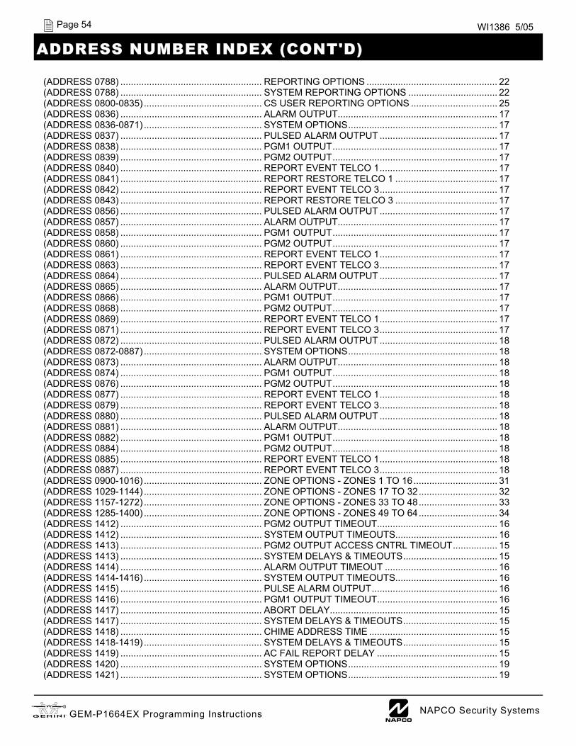
X GEM-P1664EX Programming Instructions L NAPCO Security Systems
Page 54 WI1386 5/05
ADDRESS NUMBER INDEX (CONT'D)
(ADDRESS 0788) ...................................................... REPORTING OPTIONS .................................................. 22 (ADDRESS 0788) ...................................................... SYSTEM REPORTING OPTIONS .................................. 22 (ADDRESS 0800-0835) ............................................. CS USER REPORTING OPTIONS ................................. 25 (ADDRESS 0836) ...................................................... ALARM OUTPUT ............................................................. 17 (ADDRESS 0836-0871) ............................................. SYSTEM OPTIONS ......................................................... 17 (ADDRESS 0837) ...................................................... PULSED ALARM OUTPUT ............................................. 17 (ADDRESS 0838) ...................................................... PGM1 OUTPUT ............................................................... 17 (ADDRESS 0839) ...................................................... PGM2 OUTPUT ............................................................... 17 (ADDRESS 0840) ...................................................... REPORT EVENT TELCO 1 ............................................. 17 (ADDRESS 0841) ...................................................... REPORT RESTORE TELCO 1 ....................................... 17 (ADDRESS 0842) ...................................................... REPORT EVENT TELCO 3 ............................................. 17 (ADDRESS 0843) ...................................................... REPORT RESTORE TELCO 3 ....................................... 17 (ADDRESS 0856) ...................................................... PULSED ALARM OUTPUT ............................................. 17 (ADDRESS 0857) ...................................................... ALARM OUTPUT ............................................................. 17 (ADDRESS 0858) ...................................................... PGM1 OUTPUT ............................................................... 17 (ADDRESS 0860) ...................................................... PGM2 OUTPUT ............................................................... 17 (ADDRESS 0861) ...................................................... REPORT EVENT TELCO 1 ............................................. 17 (ADDRESS 0863) ...................................................... REPORT EVENT TELCO 3 ............................................. 17 (ADDRESS 0864) ...................................................... PULSED ALARM OUTPUT ............................................. 17 (ADDRESS 0865) ...................................................... ALARM OUTPUT ............................................................. 17 (ADDRESS 0866) ...................................................... PGM1 OUTPUT ............................................................... 17 (ADDRESS 0868) ...................................................... PGM2 OUTPUT ............................................................... 17 (ADDRESS 0869) ...................................................... REPORT EVENT TELCO 1 ............................................. 17 (ADDRESS 0871) ...................................................... REPORT EVENT TELCO 3 ............................................. 17 (ADDRESS 0872) ...................................................... PULSED ALARM OUTPUT ............................................. 18 (ADDRESS 0872-0887) ............................................. SYSTEM OPTIONS ......................................................... 18 (ADDRESS 0873) ...................................................... ALARM OUTPUT ............................................................. 18 (ADDRESS 0874) ...................................................... PGM1 OUTPUT ............................................................... 18 (ADDRESS 0876) ...................................................... PGM2 OUTPUT ............................................................... 18 (ADDRESS 0877) ...................................................... REPORT EVENT TELCO 1 ............................................. 18 (ADDRESS 0879) ...................................................... REPORT EVENT TELCO 3 ............................................. 18 (ADDRESS 0880) ...................................................... PULSED ALARM OUTPUT ............................................. 18 (ADDRESS 0881) ...................................................... ALARM OUTPUT ............................................................. 18 (ADDRESS 0882) ...................................................... PGM1 OUTPUT ............................................................... 18 (ADDRESS 0884) ...................................................... PGM2 OUTPUT ............................................................... 18 (ADDRESS 0885) ...................................................... REPORT EVENT TELCO 1 ............................................. 18 (ADDRESS 0887) ...................................................... REPORT EVENT TELCO 3 ............................................. 18 (ADDRESS 0900-1016) ............................................. ZONE OPTIONS - ZONES 1 TO 16 ................................ 31 (ADDRESS 1029-1144) ............................................. ZONE OPTIONS - ZONES 17 TO 32 .............................. 32 (ADDRESS 1157-1272) ............................................. ZONE OPTIONS - ZONES 33 TO 48 .............................. 33 (ADDRESS 1285-1400) ............................................. ZONE OPTIONS - ZONES 49 TO 64 .............................. 34 (ADDRESS 1412) ...................................................... PGM2 OUTPUT TIMEOUT .............................................. 16 (ADDRESS 1412) ...................................................... SYSTEM OUTPUT TIMEOUTS ....................................... 16 (ADDRESS 1413) ...................................................... PGM2 OUTPUT ACCESS CNTRL TIMEOUT ................. 15 (ADDRESS 1413) ...................................................... SYSTEM DELAYS & TIMEOUTS .................................... 15 (ADDRESS 1414) ...................................................... ALARM OUTPUT TIMEOUT ........................................... 16 (ADDRESS 1414-1416) ............................................. SYSTEM OUTPUT TIMEOUTS ....................................... 16 (ADDRESS 1415) ...................................................... PULSE ALARM OUTPUT ................................................ 16 (ADDRESS 1416) ...................................................... PGM1 OUTPUT TIMEOUT .............................................. 16 (ADDRESS 1417) ...................................................... ABORT DELAY ................................................................ 15 (ADDRESS 1417) ...................................................... SYSTEM DELAYS & TIMEOUTS .................................... 15 (ADDRESS 1418) ...................................................... CHIME ADDRESS TIME ................................................. 15 (ADDRESS 1418-1419) ............................................. SYSTEM DELAYS & TIMEOUTS .................................... 15 (ADDRESS 1419) ...................................................... AC FAIL REPORT DELAY .............................................. 15 (ADDRESS 1420) ...................................................... SYSTEM OPTIONS ......................................................... 19 (ADDRESS 1421) ...................................................... SYSTEM OPTIONS ......................................................... 19

L NAPCO Security Systems X GEM-P1664EX Programming Instructions
Page 55 WI1386 5/05
ADDRESS NUMBER INDEX (CONT'D)
(ADDRESS 1422) ...................................................... SYSTEM OPTIONS ......................................................... 19 (ADDRESS 1423) ...................................................... SYSTEM OPTIONS ......................................................... 19 (ADDRESS 1424) ...................................................... SYSTEM OPTIONS ......................................................... 19 (ADDRESS 1425-1431) ............................................. ENABLE KEYPAD TYPE & ACTIVATION ....................... 28 (ADDRESS 1425-1431) ............................................. KEYPAD OPTIONS ......................................................... 28 (ADDRESS 1425-1431) ............................................. KEYPAD TYPE & ACTIVATION ...................................... 28 (ADDRESS 1440-1446) ............................................. ENABLE KEYPAD OPTIONS .......................................... 28 (ADDRESS 1440-1446) ............................................. KEYPAD OPTIONS ......................................................... 28 (ADDRESS 1455-1468) ............................................. EZM GROUP OPTIONS .................................................. 26 (ADDRESS 1469) ...................................................... PRIORITY ARMING AREA 1 ........................................... 30 (ADDRESS 1469-1472) ............................................. AREA ARMING OPTIONS .............................................. 30 (ADDRESS 1470) ...................................................... PRIORITY ARMING AREA 2 ........................................... 30 (ADDRESS 1471) ...................................................... PRIORITY ARMING AREA 3 ........................................... 30 (ADDRESS 1472) ...................................................... PRIORITY ARMING AREA 4 ........................................... 30 (ADDRESS 1473-1480) ............................................. BURGLARY OUTPUT TURNS OFF UPON DISARM ..... 27 (ADDRESS 1473-1488) ............................................. AREA BELL CONTROL OPTIONS ................................. 27 (ADDRESS 1481-1488) ............................................. PGM1 OUTPUT TURNS OFF UPON DISARM ............... 27 (ADDRESS 1489-1648) ............................................. EXTERNAL RELAY CONTROL ...................................... 35 (ADDRESS 1489-1648) ............................................. RELAY CONTROL (EXTERNAL) .................................... 35 (ADDRESS 1666) ...................................................... TEMPERATURE LOWER LIMIT ..................................... 29 (ADDRESS 1666-1668) ............................................. TEMPERATURE DISPLAY AT KEYPAD ........................ 29 (ADDRESS 1667) ...................................................... TEMPERATURE UPPER LIMIT ...................................... 29 (ADDRESS 1668) ...................................................... ENABLE TEMPERATURE OPTIONS ............................. 29 (ADDRESS 2029-2044) ............................................. RF RECEIVER & SUPERVISORY TIMER OPTIONS ..... 38 (ADDRESS 2045) ...................................................... GLOBAL AMBUSH CODE ............................................... 17 (ADDRESS 2045) ...................................................... SYSTEM OPTIONS ......................................................... 17 (ADDRESS 2050) ...................................................... SENSOR WATCH TIME .................................................. 15 (ADDRESS 2050) ...................................................... SYSTEM DELAYS & TIMEOUTS .................................... 15 (ADDRESS 2051) ...................................................... SYSTEM OPTIONS ......................................................... 19 (ADDRESS 2051-2054) ............................................. SYSTEM OPTIONS ......................................................... 19 (ADDRESS 2052) ...................................................... E15 LUG / SYSTEM OPTIONS ....................................... 19 (ADDRESS 2053) ...................................................... SYSTEM OPTIONS ......................................................... 19 (ADDRESS 2054) ...................................................... SYSTEM OPTIONS ......................................................... 19 (ADDRESS 2055) ...................................................... REPORT CANCEL WINDOW ......................................... 15 (ADDRESS 2055) ...................................................... SYSTEM DELAYS & TIMEOUTS .................................... 15 (ADDRESS 2056) ...................................................... NUMBER OF RF RECEIVERS ........................................ 38 (ADDRESS 2056) ...................................................... RF RECEIVER & SUPERVISORY TIMER OPTIONS ..... 38 (ADDRESS 2059) ...................................................... DOWNLOAD/CALLBACK OPTIONS ............................... 16 (ADDRESS 2059) ...................................................... NO. RINGS BEFORE PICKUP ........................................ 16 (ADDRESS 2059) ...................................................... NUMBER OF RINGS BEFORE PICKUP ......................... 16 (ADDRESS 2060) ...................................................... KEYPAD UNBLANKING TIME WINDOW ....................... 23 (ADDRESS 2061) ...................................................... ZONE ANDING TIME WINDOW ..................................... 23 (ADDRESS 2062) ...................................................... ZONE INTEGRATION TIME ............................................ 30 (ADDRESS 2062) ...................................................... ZONE RESPONSE TIME ................................................ 30 (ADDRESS 2281) ...................................................... CLOCK ADJUSTMENTS ................................................. 23 (ADDRESS 2285) ...................................................... ERASING DEALER PROGRAM ...................................... 39 (ADDRESS 2286) ...................................................... COLD START .................................................................. 39

X GEM-P1664EX Programming Instructions L NAPCO Security Systems
Page 56 WI1386 5/05 G
EM-P
1664
EX W
iring
Dia
gram
GEM-P1664EX WIRING DIAGRAM