Manual Caravan
530
CESSNA INTRODUCTION MODEL 208 G1000 U.S. NOTICE AT THE TIME OF ISSUANCE, THIS INFORMATION MANUAL WAS AN EXACT DUPLICATE OF THE OFFICIAL PILOT’S OPERATING HANDBOOK AND FAA APPROVED AIRPLANE FLIGHT MANUAL AND IS TO BE USED FOR GENERAL PURPOSES ONLY. IT WILL NOT BE KEPT CURRENT AND, THEREFORE, CANNOT BE USED AS A SUBSTITUTE FOR THE OFFICIAL PILOT’S OPERATING HANDBOOK AND FAA APPROVED AIRPLANE FLIGHT MANUAL INTENDED FOR OPERATION OF THE AIRPLANE. THE PILOT’S OPERATING HANDBOOK MUST BE CARRIED IN THE AIRPLANE AND AVAILABLE TO THE PILOT AT ALL TIMES. Revision 1 i
-
Upload
larissajunqueirafranco -
Category
Documents
-
view
128 -
download
4
Transcript of Manual Caravan
CESSNA INTRODUCTIONMODEL 208 G1000
U.S.
NOTICE
AT THE TIME OF ISSUANCE, THIS INFORMATION MANUALWAS AN EXACT DUPLICATE OF THE OFFICIAL PILOT’SOPERATING HANDBOOK AND FAA APPROVED AIRPLANEFLIGHT MANUAL AND IS TO BE USED FOR GENERALPURPOSES ONLY.
IT WILL NOT BE KEPT CURRENT AND, THEREFORE, CANNOTBE USED AS A SUBSTITUTE FOR THE OFFICIAL PILOT’SOPERATING HANDBOOK AND FAA APPROVED AIRPLANEFLIGHT MANUAL INTENDED FOR OPERATION OF THEAIRPLANE.
THE PILOT’S OPERATING HANDBOOK MUST BE CARRIED INTHE AIRPLANE AND AVAILABLE TO THE PILOT AT ALL TIMES.
Revision 1 i
INTRODUCTION CESSNAMODEL 208 G1000
U.S.
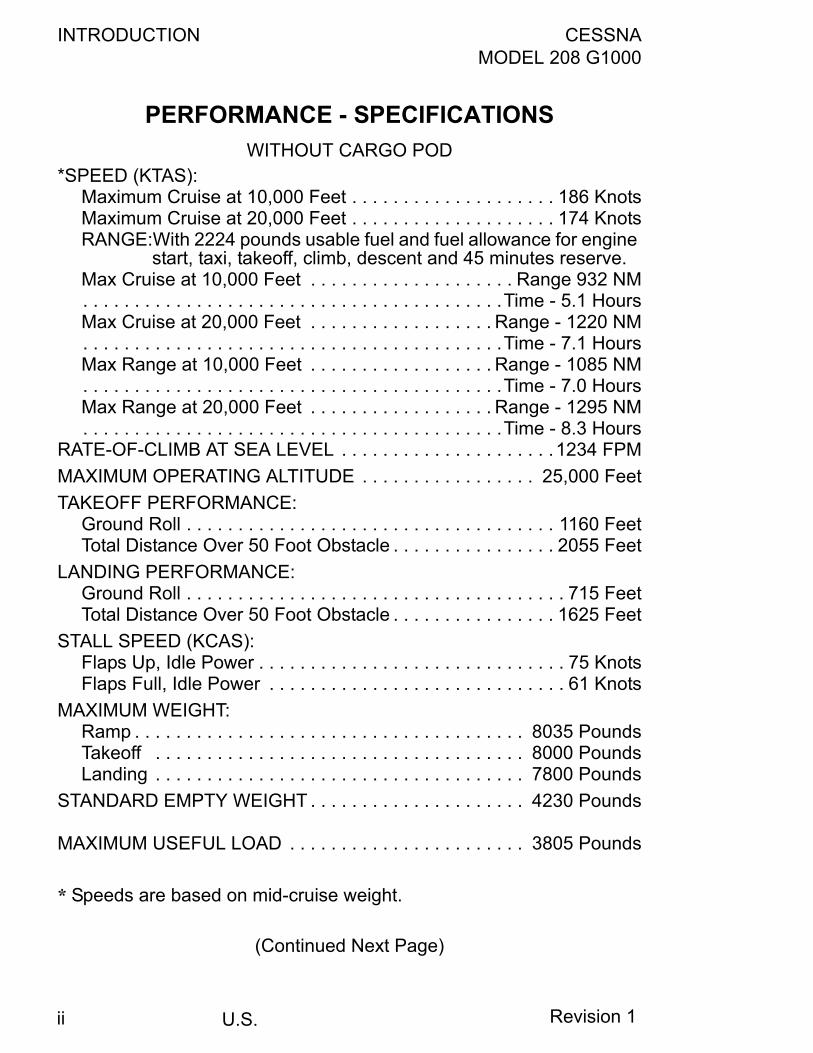
PERFORMANCE - SPECIFICATIONSWITHOUT CARGO POD
*SPEED (KTAS):Maximum Cruise at 10,000 Feet . . . . . . . . . . . . . . . . . . . . 186 KnotsMaximum Cruise at 20,000 Feet . . . . . . . . . . . . . . . . . . . . 174 KnotsRANGE:With 2224 pounds usable fuel and fuel allowance for engine
start, taxi, takeoff, climb, descent and 45 minutes reserve.Max Cruise at 10,000 Feet . . . . . . . . . . . . . . . . . . . . Range 932 NM. . . . . . . . . . . . . . . . . . . . . . . . . . . . . . . . . . . . . . . . .Time - 5.1 HoursMax Cruise at 20,000 Feet . . . . . . . . . . . . . . . . . . Range - 1220 NM. . . . . . . . . . . . . . . . . . . . . . . . . . . . . . . . . . . . . . . . .Time - 7.1 HoursMax Range at 10,000 Feet . . . . . . . . . . . . . . . . . . Range - 1085 NM. . . . . . . . . . . . . . . . . . . . . . . . . . . . . . . . . . . . . . . . .Time - 7.0 HoursMax Range at 20,000 Feet . . . . . . . . . . . . . . . . . . Range - 1295 NM. . . . . . . . . . . . . . . . . . . . . . . . . . . . . . . . . . . . . . . . .Time - 8.3 Hours
RATE-OF-CLIMB AT SEA LEVEL . . . . . . . . . . . . . . . . . . . . .1234 FPMMAXIMUM OPERATING ALTITUDE . . . . . . . . . . . . . . . . . 25,000 FeetTAKEOFF PERFORMANCE:
Ground Roll . . . . . . . . . . . . . . . . . . . . . . . . . . . . . . . . . . . . 1160 FeetTotal Distance Over 50 Foot Obstacle . . . . . . . . . . . . . . . . 2055 Feet
LANDING PERFORMANCE:Ground Roll . . . . . . . . . . . . . . . . . . . . . . . . . . . . . . . . . . . . . 715 FeetTotal Distance Over 50 Foot Obstacle . . . . . . . . . . . . . . . . 1625 Feet
STALL SPEED (KCAS):Flaps Up, Idle Power . . . . . . . . . . . . . . . . . . . . . . . . . . . . . . 75 KnotsFlaps Full, Idle Power . . . . . . . . . . . . . . . . . . . . . . . . . . . . . 61 Knots
MAXIMUM WEIGHT:Ramp . . . . . . . . . . . . . . . . . . . . . . . . . . . . . . . . . . . . . . 8035 PoundsTakeoff . . . . . . . . . . . . . . . . . . . . . . . . . . . . . . . . . . . . 8000 PoundsLanding . . . . . . . . . . . . . . . . . . . . . . . . . . . . . . . . . . . . 7800 Pounds
STANDARD EMPTY WEIGHT . . . . . . . . . . . . . . . . . . . . . 4230 Pounds
MAXIMUM USEFUL LOAD . . . . . . . . . . . . . . . . . . . . . . . 3805 Pounds
* Speeds are based on mid-cruise weight.
(Continued Next Page)
Revision 1ii
CESSNA INTRODUCTIONMODEL 208 G1000
U.S.
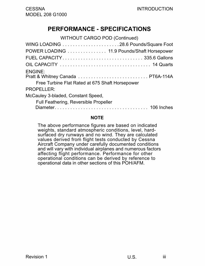
PERFORMANCE - SPECIFICATIONSWITHOUT CARGO POD (Continued)
WING LOADING . . . . . . . . . . . . . . . . . . . . . . 28.6 Pounds/Square FootPOWER LOADING . . . . . . . . . . . . . . . 11.9 Pounds/Shaft HorsepowerFUEL CAPACITY. . . . . . . . . . . . . . . . . . . . . . . . . . . . . . . 335.6 Gallons OIL CAPACITY . . . . . . . . . . . . . . . . . . . . . . . . . . . . . . . . . . . 14 QuartsENGINE:Pratt & Whitney Canada . . . . . . . . . . . . . . . . . . . . . . . . . . . PT6A-114A
Free Turbine Flat Rated at 675 Shaft HorsepowerPROPELLER:McCauley 3-bladed, Constant Speed,
Full Feathering, Reversible Propeller Diameter. . . . . . . . . . . . . . . . . . . . . . . . . . . . . . . . . . . . 106 Inches
NOTEThe above performance figures are based on indicatedweights, standard atmospheric conditions, level, hard-surfaced dry runways and no wind. They are calculatedvalues derived from flight tests conducted by CessnaAircraft Company under carefully documented conditionsand will vary with individual airplanes and numerous factorsaffecting flight performance. Performance for otheroperational conditions can be derived by reference tooperational data in other sections of this POH/AFM.
Revision 1 iii

INTRODUCTION CESSNAMODEL 208 G1000
U.S.
PERFORMANCE - SPECIFICATIONSWITH CARGO POD
* SPEED (KTAS):Maximum Cruise at 10,000 Feet . . . . . . . . . . . . . . . . . . . . 177 KnotsMaximum Cruise at 20,000 Feet . . . . . . . . . . . . . . . . . . . . 165 KnotsRANGE:With 2224 pounds usable fuel and fuel allowance for engine
start, taxi, takeoff, climb, descent and 45 minutes reserve.Max Cruise at 10,000 Feet . . . . . . . . . . . . . . . . . . . Range - 891 NM. . . . . . . . . . . . . . . . . . . . . . . . . . . . . . . . . . . . . . . . .Time - 5.1 HoursMax Cruise at 20,000 Feet . . . . . . . . . . . . . . . . . . Range - 1155 NM. . . . . . . . . . . . . . . . . . . . . . . . . . . . . . . . . . . . . . . . .Time - 7.1 HoursMax Range at 10,000 Feet . . . . . . . . . . . . . . . . . . Range - 1028 NM. . . . . . . . . . . . . . . . . . . . . . . . . . . . . . . . . . . . . . . . .Time - 6.9 HoursMax Range at 20,000 Feet . . . . . . . . . . . . . . . . . . Range - 1199 NM. . . . . . . . . . . . . . . . . . . . . . . . . . . . . . . . . . . . . . . . .Time - 7.9 Hours
RATE-OF-CLIMB AT SEA LEVEL . . . . . . . . . . . . . . . . . . . . . 1175 FPMMAXIMUM OPERATING ALTITUDE . . . . . . . . . . . . . . . . . 25,000 FeetTAKEOFF PERFORMANCE:
Ground Roll . . . . . . . . . . . . . . . . . . . . . . . . . . . . . . . . . . . . 1170 FeetTotal Distance Over 50 Foot Obstacle . . . . . . . . . . . . . . . 2090 Feet
LANDING PERFORMANCE:Ground Roll . . . . . . . . . . . . . . . . . . . . . . . . . . . . . . . . . . . . . 710 FeetTotal Distance Over 50 Foot Obstacle . . . . . . . . . . . . . . . . 1600 Feet
STALL SPEED (KCAS):Flaps Up, Idle Power . . . . . . . . . . . . . . . . . . . . . . . . . . . . . . 75 KnotsFlaps Full, Idle Power . . . . . . . . . . . . . . . . . . . . . . . . . . . . . 61 Knots
MAXIMUM WEIGHT:Ramp . . . . . . . . . . . . . . . . . . . . . . . . . . . . . . . . . . . . . . 8035 PoundsTakeoff . . . . . . . . . . . . . . . . . . . . . . . . . . . . . . . . . . . . . 8000 PoundsLanding . . . . . . . . . . . . . . . . . . . . . . . . . . . . . . . . . . . . 7800 Pounds
STANDARD EMPTY WEIGHT . . . . . . . . . . . . . . . . . . . . . 4230 PoundsMAXIMUM USEFUL LOAD . . . . . . . . . . . . . . . . . . . . . . . 3805 Pounds
* Speeds are based on mid-cruise weight.
(Continued Next Page)
Revision 1iv
CESSNA INTRODUCTIONMODEL 208 G1000
U.S.
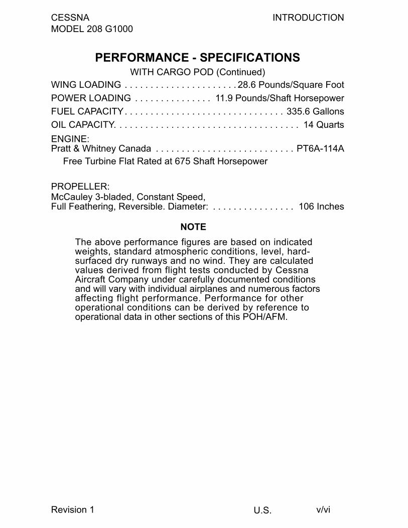
PERFORMANCE - SPECIFICATIONSWITH CARGO POD (Continued)
WING LOADING . . . . . . . . . . . . . . . . . . . . . . 28.6 Pounds/Square FootPOWER LOADING . . . . . . . . . . . . . . . 11.9 Pounds/Shaft HorsepowerFUEL CAPACITY. . . . . . . . . . . . . . . . . . . . . . . . . . . . . . . 335.6 GallonsOIL CAPACITY. . . . . . . . . . . . . . . . . . . . . . . . . . . . . . . . . . . . 14 QuartsENGINE:Pratt & Whitney Canada . . . . . . . . . . . . . . . . . . . . . . . . . . . PT6A-114A
Free Turbine Flat Rated at 675 Shaft Horsepower
PROPELLER:McCauley 3-bladed, Constant Speed,Full Feathering, Reversible. Diameter: . . . . . . . . . . . . . . . . 106 Inches
NOTEThe above performance figures are based on indicatedweights, standard atmospheric conditions, level, hard-surfaced dry runways and no wind. They are calculatedvalues derived from flight tests conducted by CessnaAircraft Company under carefully documented conditionsand will vary with individual airplanes and numerous factorsaffecting flight performance. Performance for otheroperational conditions can be derived by reference tooperational data in other sections of this POH/AFM.
Revision 1 v/vi

CESSNA INTRODUCTIONMODEL 208 G1000
U.S.
Cessna Aircraft Company
Model 208 G1000
This manual incorporates information issued in the Pilot's OperatingHandbook and FAA approved Airplane Flight Manual at Revision 1,Dated 5 June 2008 (Part Number 208PHBUS-01).
COPYRIGHT © 2008CESSNA AIRCRAFT COMPANY
WICHITA, KANSAS, USA
208IMBUS-01 vii/viii

CESSNA INTRODUCTIONMODEL 208 G1000
U.S. xv
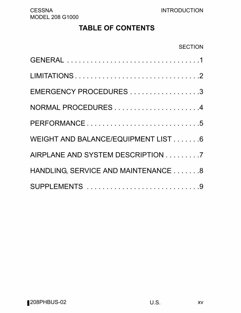
TABLE OF CONTENTS
SECTION
GENERAL . . . . . . . . . . . . . . . . . . . . . . . . . . . . . . . . . .1
LIMITATIONS . . . . . . . . . . . . . . . . . . . . . . . . . . . . . . . .2
EMERGENCY PROCEDURES . . . . . . . . . . . . . . . . . .3
NORMAL PROCEDURES . . . . . . . . . . . . . . . . . . . . . .4
PERFORMANCE . . . . . . . . . . . . . . . . . . . . . . . . . . . . .5
WEIGHT AND BALANCE/EQUIPMENT LIST . . . . . . .6
AIRPLANE AND SYSTEM DESCRIPTION . . . . . . . . .7
HANDLING, SERVICE AND MAINTENANCE . . . . . . .8
SUPPLEMENTS . . . . . . . . . . . . . . . . . . . . . . . . . . . . .9
208PHBUS-02

INTRODUCTION CESSNA MODEL 208 G1000
U.S.xvi
This Page Intentionally Left Blank
208PHBUS-02
CESSNA SECTION 1MODEL 208 G1000 GENERAL
U.S. 1-1
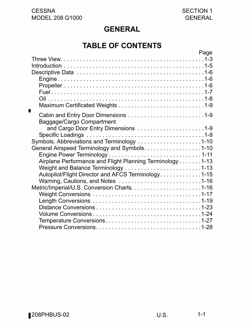
GENERAL
TABLE OF CONTENTSPage
Three View. . . . . . . . . . . . . . . . . . . . . . . . . . . . . . . . . . . . . . . . . . . . .1-3Introduction . . . . . . . . . . . . . . . . . . . . . . . . . . . . . . . . . . . . . . . . . . . .1-5Descriptive Data . . . . . . . . . . . . . . . . . . . . . . . . . . . . . . . . . . . . . . . .1-6
Engine . . . . . . . . . . . . . . . . . . . . . . . . . . . . . . . . . . . . . . . . . . . . . .1-6Propeller . . . . . . . . . . . . . . . . . . . . . . . . . . . . . . . . . . . . . . . . . . . .1-6Fuel . . . . . . . . . . . . . . . . . . . . . . . . . . . . . . . . . . . . . . . . . . . . . . . .1-7Oil . . . . . . . . . . . . . . . . . . . . . . . . . . . . . . . . . . . . . . . . . . . . . . . . .1-8Maximum Certificated Weights . . . . . . . . . . . . . . . . . . . . . . . . . . .1-9
Cabin and Entry Door Dimensions . . . . . . . . . . . . . . . . . . . . . . . .1-9Baggage/Cargo Compartment and Cargo Door Entry Dimensions . . . . . . . . . . . . . . . . . . . . .1-9Specific Loadings . . . . . . . . . . . . . . . . . . . . . . . . . . . . . . . . . . . . .1-9
Symbols, Abbreviations and Terminology . . . . . . . . . . . . . . . . . . . .1-10General Airspeed Terminology and Symbols. . . . . . . . . . . . . . . . . .1-10
Engine Power Terminology . . . . . . . . . . . . . . . . . . . . . . . . . . . . . 1-11Airplane Performance and Flight Planning Terminology . . . . . . .1-13Weight and Balance Terminology . . . . . . . . . . . . . . . . . . . . . . . .1-13Autopilot/Flight Director and AFCS Terminology. . . . . . . . . . . . .1-15Warning, Cautions, and Notes . . . . . . . . . . . . . . . . . . . . . . . . . .1-16
Metric/Imperial/U.S. Conversion Charts. . . . . . . . . . . . . . . . . . . . . .1-16Weight Conversions . . . . . . . . . . . . . . . . . . . . . . . . . . . . . . . . . .1-17Length Conversions . . . . . . . . . . . . . . . . . . . . . . . . . . . . . . . . . .1-19Distance Conversions . . . . . . . . . . . . . . . . . . . . . . . . . . . . . . . . .1-23Volume Conversions . . . . . . . . . . . . . . . . . . . . . . . . . . . . . . . . . .1-24Temperature Conversions . . . . . . . . . . . . . . . . . . . . . . . . . . . . . .1-27Pressure Conversions. . . . . . . . . . . . . . . . . . . . . . . . . . . . . . . . .1-28
208PHBUS-02

SECTION 1 CESSNAGENERAL MODEL 208 G1000
U.S.1-2
This Page Intentionally Left Blank
208PHBUS-02
CESSNA SECTION 1MODEL 208 G1000 GENERAL
U.S. 1-3
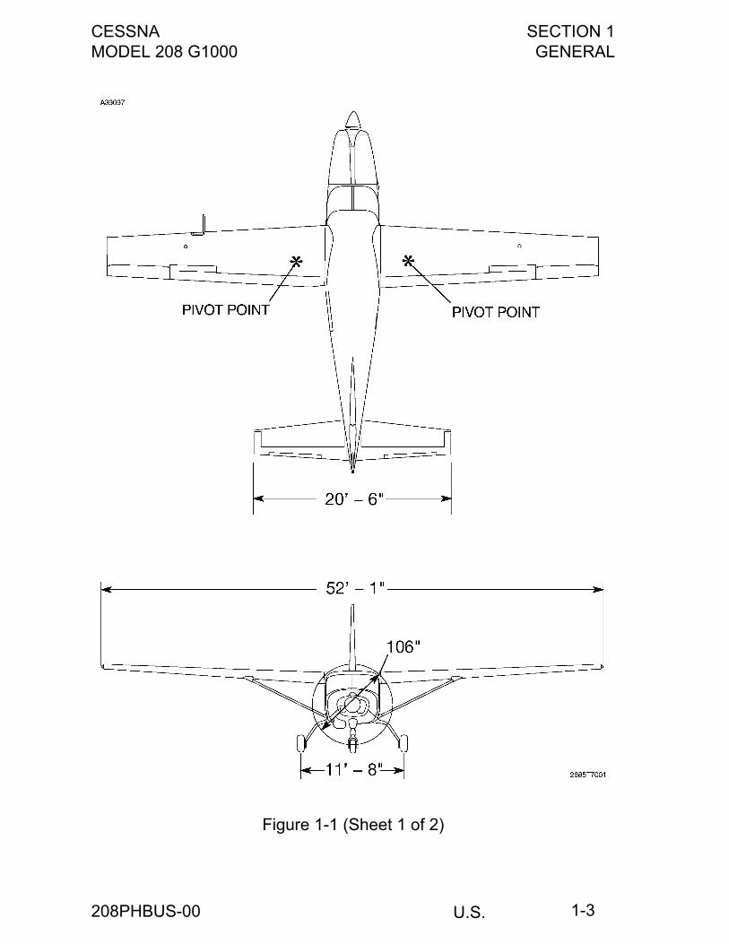
Figure 1-1 (Sheet 1 of 2)
208PHBUS-00
SECTION 1 CESSNAGENERAL MODEL 208 G1000
U.S.1-4
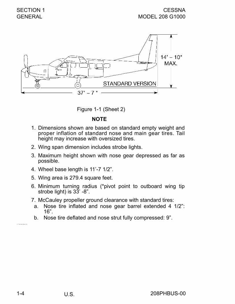
Figure 1-1 (Sheet 2)
NOTE
1. Dimensions shown are based on standard empty weight andproper inflation of standard nose and main gear tires. Tailheight may increase with oversized tires.
2. Wing span dimension includes strobe lights.
3. Maximum height shown with nose gear depressed as far aspossible.
4. Wheel base length is 11’-7 1/2”.
5. Wing area is 279.4 square feet.
6. Minimum turning radius (*pivot point to outboard wing tipstrobe light) is 33’ -8”.
7. McCauley propeller ground clearance with standard tires: a. Nose tire inflated and nose gear barrel extended 4 1/2”:
16”. b. Nose tire deflated and nose strut fully compressed: 9”.
1-1*. Three View (Sheet 2 of 2)
208PHBUS-00
CESSNA SECTION 1MODEL 208 G1000 GENERAL
U.S. 1-5
INTRODUCTIONThis POH/AFM contains 9 sections, and includes the material requiredto be furnished to the pilot by Federal Aviation Regulations andadditional information provided by Cessna Aircraft Company. Thishandbook constitutes the FAA Approved Airplane Flight Manual.
WARNING
• This POH/AFM is not intended to be a guide forbasic flight instruction or a training manual andshould not be used as one. It is not a substitutefor adequate and competent flight instruction,pilot skill, and pilot knowledge of currentAirworthiness Directives, applicable federalaviation regulations and/or advisory circulars.
• Assuring the airworthiness of the airplane is theresponsibility of the airplane owner or operator.Determining if the airplane is safe for flight is theresponsibility of the pilot in command. The pilotis also responsible for adhering to the operatinglimitations set forth by instrument markings,placards, and this POH/AFM.
Section 1 provides basic data and information of general interest. Italso contains definitions or explanations of symbols, abbreviations, andterminology commonly used.
208PHBUS-00
SECTION 1 CESSNAGENERAL MODEL 208 G1000
U.S.1-6
DESCRIPTIVE DATA
ENGINENumber of Engines . . . . . . . . . . . . . . . . . . . . . . . . . . . . . . . . . . . . . 1Engine Manufacturer . . . . . . . . . . . . . Pratt & Whitney Canada, Inc.Engine Model Number . . . . . . . . . . . . . . . . . . . . . . . . . . PT6A-114AEngine Type: Free turbine, two-shaft engine utilizing a compressor section havingthree axial stages and one centrifugal stage, an annular reverse-flowcombustion chamber, a one-stage compressor turbine, a one-stagepower turbine, and a single exhaust. The power turbine drives thepropeller through a two-stage planetary gearbox at the front of theengine.
Horsepower . . . . . . . . . . . . . . . . Flat rated at 675 shaft horsepower.
PROPELLERMcCauley:
Propeller Manufacturer . . . . . . . . . . . McCauley Accessory DivisionPropeller Model Number . . . . . . . . . . . . . . . 3GFR34C703/106GA-0Number of Blades . . . . . . . . . . . . . . . . . . . . . . . . . . . . . . . . . . . . . . 3Propeller Diameter. . . . . . . . . . . . . . . . . . . . . . Maximum 106 Inches
Minimum 104 InchesPropeller Type: Constant-speed, full-feathering, reversible, hydraulically-actuatedaluminum-bladed propeller, with a feathered blade angle of 88°, alow pitch blade angle of 15.6°, and a maximum reverse blade angleof -14° (30-inch station).
Hartzell:Propeller Manufacturer . . . . . . . . . . . . . .Hartzell Propeller ProductsPropeller Model Number . . . . . . . . . . . . . . . . . HC-B3MN-3/M10083Number of Blades . . . . . . . . . . . . . . . . . . . . . . . . . . . . . . . . . . . . . . 3Propeller Diameter. . . . . . . . . . . . . . . . . . . . . . Maximum 100 Inches
Minimum 100 Inches(No cutoff approved)
Propeller Type: Constant-speed, full-feathering, reversible, hydraulically-actuatedcomposite-bladed propeller, with a feathered blade angle of 78.4°, alow pitch blade angle of 9°, and a maximum reverse blade angle of-18° (42-inch station).
208PHBUS-02
CESSNA SECTION 1MODEL 208 G1000 GENERAL
U.S. 1-7
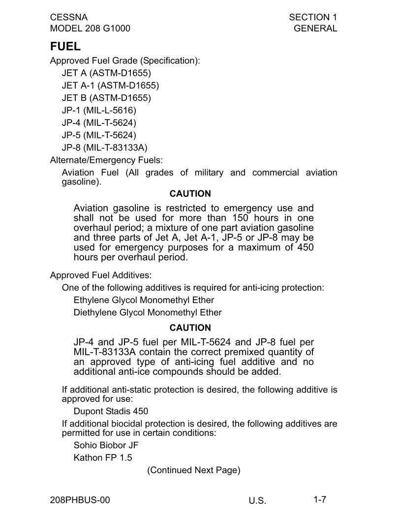
FUELApproved Fuel Grade (Specification):
JET A (ASTM-D1655)JET A-1 (ASTM-D1655)JET B (ASTM-D1655)JP-1 (MIL-L-5616)JP-4 (MIL-T-5624)JP-5 (MIL-T-5624)JP-8 (MIL-T-83133A)
Alternate/Emergency Fuels:Aviation Fuel (All grades of military and commercial aviationgasoline).
CAUTION
Aviation gasoline is restricted to emergency use andshall not be used for more than 150 hours in oneoverhaul period; a mixture of one part aviation gasolineand three parts of Jet A, Jet A-1, JP-5 or JP-8 may beused for emergency purposes for a maximum of 450hours per overhaul period.
Approved Fuel Additives:One of the following additives is required for anti-icing protection:
Ethylene Glycol Monomethyl EtherDiethylene Glycol Monomethyl Ether
CAUTION
JP-4 and JP-5 fuel per MIL-T-5624 and JP-8 fuel perMIL-T-83133A contain the correct premixed quantity ofan approved type of anti-icing fuel additive and noadditional anti-ice compounds should be added.
If additional anti-static protection is desired, the following additive isapproved for use:
Dupont Stadis 450If additional biocidal protection is desired, the following additives arepermitted for use in certain conditions:
Sohio Biobor JFKathon FP 1.5
(Continued Next Page)
208PHBUS-00
SECTION 1 CESSNAGENERAL MODEL 208 G1000
U.S.1-8
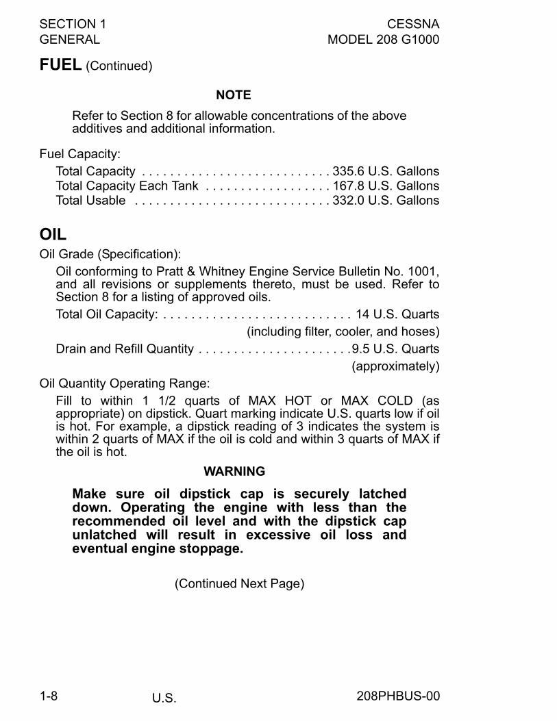
FUEL (Continued)
NOTE
Refer to Section 8 for allowable concentrations of the aboveadditives and additional information.
Fuel Capacity:Total Capacity . . . . . . . . . . . . . . . . . . . . . . . . . . . 335.6 U.S. GallonsTotal Capacity Each Tank . . . . . . . . . . . . . . . . . . 167.8 U.S. GallonsTotal Usable . . . . . . . . . . . . . . . . . . . . . . . . . . . . 332.0 U.S. Gallons
OILOil Grade (Specification):
Oil conforming to Pratt & Whitney Engine Service Bulletin No. 1001,and all revisions or supplements thereto, must be used. Refer toSection 8 for a listing of approved oils.Total Oil Capacity: . . . . . . . . . . . . . . . . . . . . . . . . . . . 14 U.S. Quarts
(including filter, cooler, and hoses)Drain and Refill Quantity . . . . . . . . . . . . . . . . . . . . . .9.5 U.S. Quarts
(approximately)Oil Quantity Operating Range:
Fill to within 1 1/2 quarts of MAX HOT or MAX COLD (asappropriate) on dipstick. Quart marking indicate U.S. quarts low if oilis hot. For example, a dipstick reading of 3 indicates the system iswithin 2 quarts of MAX if the oil is cold and within 3 quarts of MAX ifthe oil is hot.
WARNING
Make sure oil dipstick cap is securely latcheddown. Operating the engine with less than therecommended oil level and with the dipstick capunlatched will result in excessive oil loss andeventual engine stoppage.
(Continued Next Page)
208PHBUS-00
CESSNA SECTION 1MODEL 208 G1000 GENERAL
U.S. 1-9
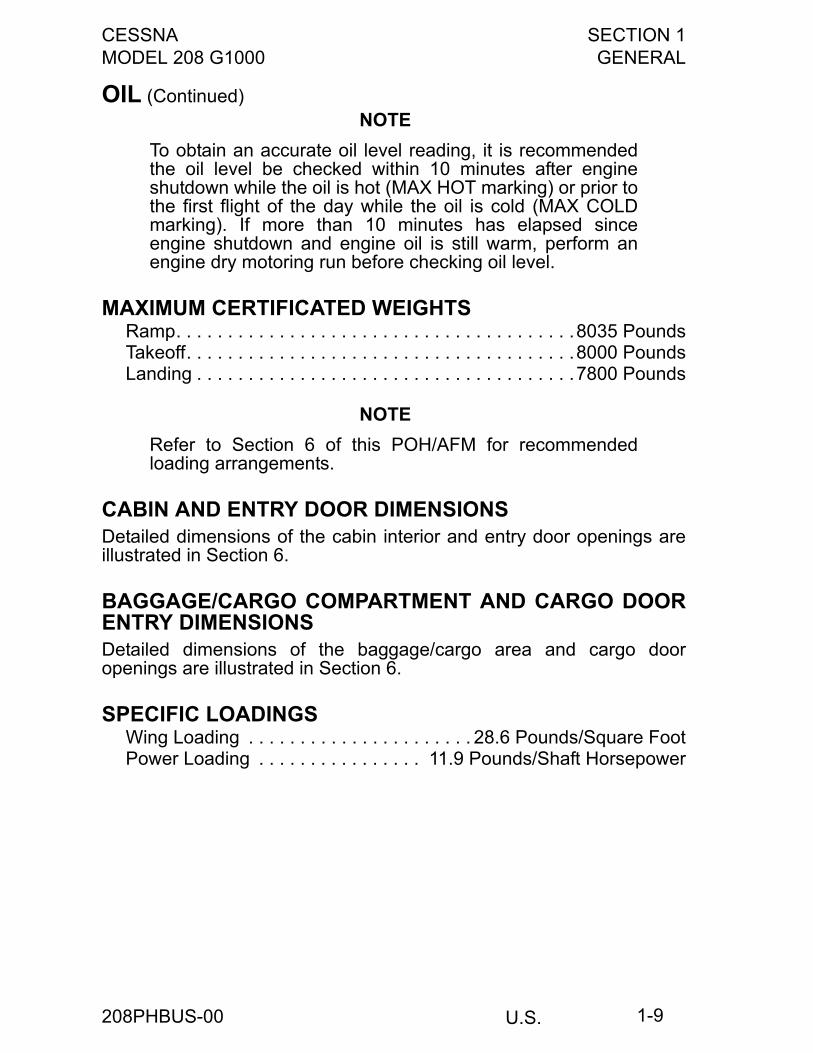
OIL (Continued) NOTE
To obtain an accurate oil level reading, it is recommendedthe oil level be checked within 10 minutes after engineshutdown while the oil is hot (MAX HOT marking) or prior tothe first flight of the day while the oil is cold (MAX COLDmarking). If more than 10 minutes has elapsed sinceengine shutdown and engine oil is still warm, perform anengine dry motoring run before checking oil level.
MAXIMUM CERTIFICATED WEIGHTSRamp. . . . . . . . . . . . . . . . . . . . . . . . . . . . . . . . . . . . . . .8035 PoundsTakeoff. . . . . . . . . . . . . . . . . . . . . . . . . . . . . . . . . . . . . .8000 PoundsLanding . . . . . . . . . . . . . . . . . . . . . . . . . . . . . . . . . . . . .7800 Pounds
NOTE
Refer to Section 6 of this POH/AFM for recommendedloading arrangements.
CABIN AND ENTRY DOOR DIMENSIONSDetailed dimensions of the cabin interior and entry door openings areillustrated in Section 6.
BAGGAGE/CARGO COMPARTMENT AND CARGO DOORENTRY DIMENSIONSDetailed dimensions of the baggage/cargo area and cargo dooropenings are illustrated in Section 6.
SPECIFIC LOADINGSWing Loading . . . . . . . . . . . . . . . . . . . . . . 28.6 Pounds/Square FootPower Loading . . . . . . . . . . . . . . . . 11.9 Pounds/Shaft Horsepower
208PHBUS-00
SECTION 1 CESSNAGENERAL MODEL 208 G1000
U.S.1-10
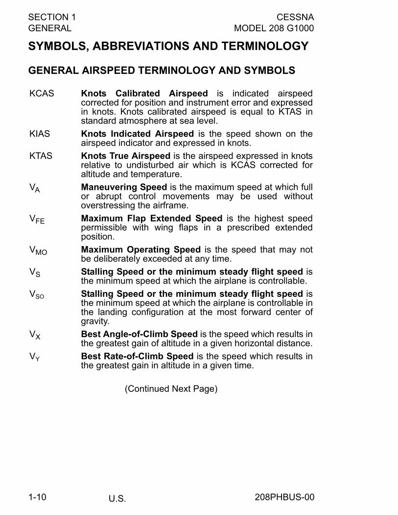
SYMBOLS, ABBREVIATIONS AND TERMINOLOGY
GENERAL AIRSPEED TERMINOLOGY AND SYMBOLS
(Continued Next Page)
KCAS Knots Calibrated Airspeed is indicated airspeedcorrected for position and instrument error and expressedin knots. Knots calibrated airspeed is equal to KTAS instandard atmosphere at sea level.
KIAS Knots Indicated Airspeed is the speed shown on theairspeed indicator and expressed in knots.
KTAS Knots True Airspeed is the airspeed expressed in knotsrelative to undisturbed air which is KCAS corrected foraltitude and temperature.
VA Maneuvering Speed is the maximum speed at which fullor abrupt control movements may be used withoutoverstressing the airframe.
VFE Maximum Flap Extended Speed is the highest speedpermissible with wing flaps in a prescribed extendedposition.
VMO Maximum Operating Speed is the speed that may notbe deliberately exceeded at any time.
VS Stalling Speed or the minimum steady flight speed isthe minimum speed at which the airplane is controllable.
VSO Stalling Speed or the minimum steady flight speed isthe minimum speed at which the airplane is controllable inthe landing configuration at the most forward center ofgravity.
VX Best Angle-of-Climb Speed is the speed which results inthe greatest gain of altitude in a given horizontal distance.
VY Best Rate-of-Climb Speed is the speed which results inthe greatest gain in altitude in a given time.
208PHBUS-00
CESSNA SECTION 1MODEL 208 G1000 GENERAL
U.S. 1-11
SYMBOLS, ABBREVIATIONS AND TERMINOLOGY(Continued)
ENGINE POWER TERMINOLOGY
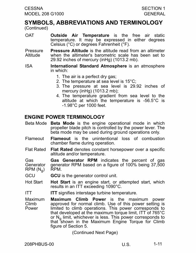
OAT Outside Air Temperature is the free air statictemperature. It may be expressed in either degreesCelsius (°C) or degrees Fahrenheit (°F).
PressureAltitude
Pressure Altitude is the altitude read from an altimeterwhen the altimeter's barometric scale has been set to29.92 inches of mercury (inHg) (1013.2 mb).
ISA International Standard Atmosphere is an atmospherein which:
1. The air is a perfect dry gas;2. The temperature at sea level is 15°C;3. The pressure at sea level is 29.92 inches of
mercury (inHg) (1013.2 mb);4. The temperature gradient from sea level to the
altitude at which the temperature is -56.5°C is-1.98°C per 1000 feet.
Beta Mode Beta Mode is the engine operational mode in whichpropeller blade pitch is controlled by the power lever. Thebeta mode may be used during ground operations only.
Flameout Flameout is the unintentional loss of combustionchamber flame during operation.
Flat Rated Flat Rated denotes constant horsepower over a specificaltitude and/or temperature.
GasGeneratorRPM (Ng)
Gas Generator RPM indicates the percent of gasgenerator RPM based on a figure of 100% being 37,500RPM.
GCU GCU is the generator control unit.
Hot Start Hot Start is an engine start, or attempted start, whichresults in an ITT exceeding 1090°C.
ITT ITT signifies interstage turbine temperature.
MaximumClimbPower
Maximum Climb Power is the maximum powerapproved for normal climb. Use of this power setting islimited to climb operations. This power corresponds tothat developed at the maximum torque limit, ITT of 765°Cor Ng limit, whichever is less. This power corresponds tothat shown in the Maximum Engine Torque for Climbfigure of Section 5.
(Continued Next Page)
208PHBUS-00
SECTION 1 CESSNAGENERAL MODEL 208 G1000
U.S.1-12
SYMBOLS, ABBREVIATIONS AND TERMINOLOGY(Continued)
MaximumRatedPower
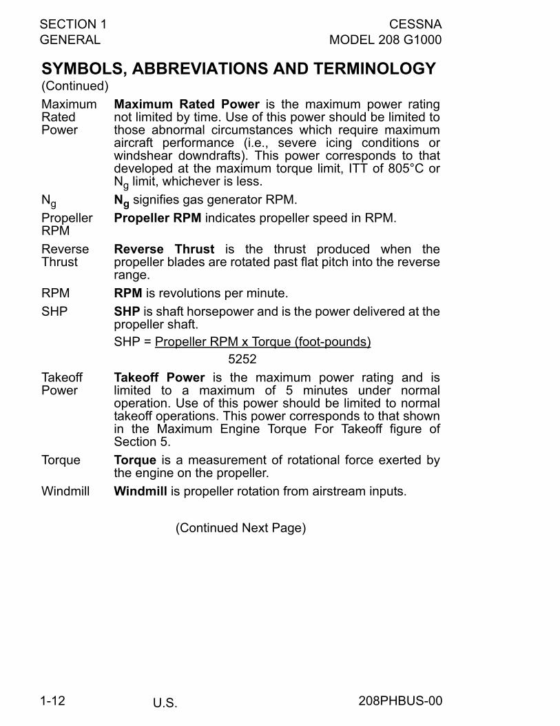
Maximum Rated Power is the maximum power ratingnot limited by time. Use of this power should be limited tothose abnormal circumstances which require maximumaircraft performance (i.e., severe icing conditions orwindshear downdrafts). This power corresponds to thatdeveloped at the maximum torque limit, ITT of 805°C orNg limit, whichever is less.
Ng Ng signifies gas generator RPM.
PropellerRPM
Propeller RPM indicates propeller speed in RPM.
ReverseThrust
Reverse Thrust is the thrust produced when thepropeller blades are rotated past flat pitch into the reverserange.
RPM RPM is revolutions per minute.
SHP SHP is shaft horsepower and is the power delivered at thepropeller shaft.SHP = Propeller RPM x Torque (foot-pounds)
5252
TakeoffPower
Takeoff Power is the maximum power rating and islimited to a maximum of 5 minutes under normaloperation. Use of this power should be limited to normaltakeoff operations. This power corresponds to that shownin the Maximum Engine Torque For Takeoff figure ofSection 5.
Torque Torque is a measurement of rotational force exerted bythe engine on the propeller.
Windmill Windmill is propeller rotation from airstream inputs.
(Continued Next Page)
208PHBUS-00
CESSNA SECTION 1MODEL 208 G1000 GENERAL
U.S. 1-13
SYMBOLS, ABBREVIATIONS AND TERMINOLOGY(Continued)
AIRPLANE PERFORMANCE AND FLIGHT PLANNINGTERMINOLOGY
WEIGHT AND BALANCE TERMINOLOGY
(Continued Next Page)
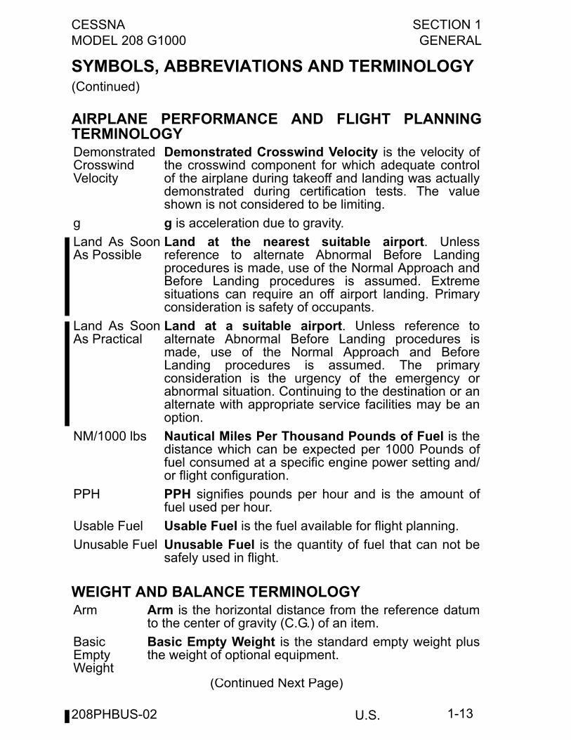
DemonstratedCrosswindVelocity
Demonstrated Crosswind Velocity is the velocity ofthe crosswind component for which adequate controlof the airplane during takeoff and landing was actuallydemonstrated during certification tests. The valueshown is not considered to be limiting.
g g is acceleration due to gravity.
Land As SoonAs Possible
Land at the nearest suitable airport. Unlessreference to alternate Abnormal Before Landingprocedures is made, use of the Normal Approach andBefore Landing procedures is assumed. Extremesituations can require an off airport landing. Primaryconsideration is safety of occupants.
Land As SoonAs Practical
Land at a suitable airport. Unless reference toalternate Abnormal Before Landing procedures ismade, use of the Normal Approach and BeforeLanding procedures is assumed. The primaryconsideration is the urgency of the emergency orabnormal situation. Continuing to the destination or analternate with appropriate service facilities may be anoption.
NM/1000 lbs Nautical Miles Per Thousand Pounds of Fuel is thedistance which can be expected per 1000 Pounds offuel consumed at a specific engine power setting and/or flight configuration.
PPH PPH signifies pounds per hour and is the amount offuel used per hour.
Usable Fuel Usable Fuel is the fuel available for flight planning.
Unusable Fuel Unusable Fuel is the quantity of fuel that can not besafely used in flight.
Arm Arm is the horizontal distance from the reference datumto the center of gravity (C.G.) of an item.
BasicEmptyWeight
Basic Empty Weight is the standard empty weight plusthe weight of optional equipment.
208PHBUS-02
SECTION 1 CESSNAGENERAL MODEL 208 G1000
U.S.1-14
SYMBOLS, ABBREVIATIONS AND TERMINOLOGY(Continued)
Center of Gravity (C.G.)
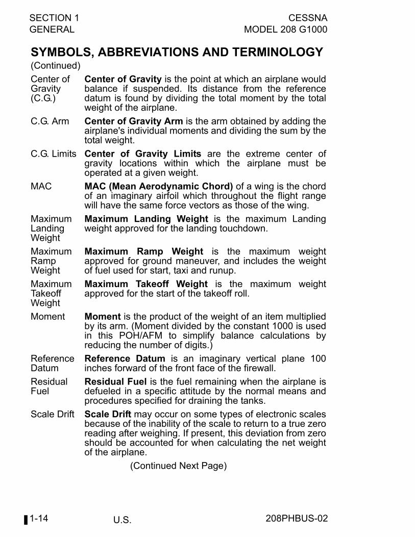
Center of Gravity is the point at which an airplane wouldbalance if suspended. Its distance from the referencedatum is found by dividing the total moment by the totalweight of the airplane.
C.G. Arm Center of Gravity Arm is the arm obtained by adding theairplane's individual moments and dividing the sum by thetotal weight.
C.G. Limits Center of Gravity Limits are the extreme center ofgravity locations within which the airplane must beoperated at a given weight.
MAC MAC (Mean Aerodynamic Chord) of a wing is the chordof an imaginary airfoil which throughout the flight rangewill have the same force vectors as those of the wing.
MaximumLandingWeight
Maximum Landing Weight is the maximum Landingweight approved for the landing touchdown.
MaximumRampWeight
Maximum Ramp Weight is the maximum weightapproved for ground maneuver, and includes the weightof fuel used for start, taxi and runup.
MaximumTakeoffWeight
Maximum Takeoff Weight is the maximum weightapproved for the start of the takeoff roll.
Moment Moment is the product of the weight of an item multipliedby its arm. (Moment divided by the constant 1000 is usedin this POH/AFM to simplify balance calculations byreducing the number of digits.)
ReferenceDatum
Reference Datum is an imaginary vertical plane 100inches forward of the front face of the firewall.
ResidualFuel
Residual Fuel is the fuel remaining when the airplane isdefueled in a specific attitude by the normal means andprocedures specified for draining the tanks.
Scale Drift Scale Drift may occur on some types of electronic scalesbecause of the inability of the scale to return to a true zeroreading after weighing. If present, this deviation from zeroshould be accounted for when calculating the net weightof the airplane.
(Continued Next Page)
208PHBUS-02
CESSNA SECTION 1MODEL 208 G1000 GENERAL
U.S. 1-15
AUTOPILOT/FLIGHT DIRECTOR AND AFCSTERMINOLOGY
CAUTION
A thorough understanding of the difference between anautopilot, a flight director, and an AFCS is requiredbefore operating any of the components of the GarminG1000/GFC 700 Flight Control System. Refer toGarmin Cockpit Resource Guide (CRG) for completeoperating details.
SYMBOLS, ABBREVIATIONS AND TERMINOLOGY(Continued)
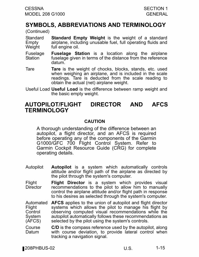
StandardEmptyWeight
Standard Empty Weight is the weight of a standardairplane, including unusable fuel, full operating fluids andfull engine oil.
FuselageStation
Fuselage Station is a location along the airplanefuselage given in terms of the distance from the referencedatum.
Tare Tare is the weight of chocks, blocks, stands, etc. usedwhen weighing an airplane, and is included in the scalereadings. Tare is deducted from the scale reading toobtain the actual (net) airplane weight.
Useful Load Useful Load is the difference between ramp weight andthe basic empty weight.
Autopilot Autopilot is a system which automatically controlsattitude and/or flight path of the airplane as directed bythe pilot through the system's computer.
FlightDirector
Flight Director is a system which provides visualrecommendations to the pilot to allow him to manuallycontrol the airplane attitude and/or flight path in responseto his desires as selected through the system's computer.
AutomatedFlightControlSystem(AFCS)
AFCS applies to the union of autopilot and flight directorsystems which allows the pilot to manage his flight byobserving computed visual recommendations while theautopilot automatically follows these recommendations asselected by the pilot using the system's controls.
CourseDatum
C/D is the compass reference used by the autopilot, alongwith course deviation, to provide lateral control whentracking a navigation signal.
208PHBUS-02
SECTION 1 CESSNAGENERAL MODEL 208 G1000
U.S.1-16
WARNINGS, CAUTIONS, AND NOTES
WARNING
An operating procedure, technique, or maintenancepractice which may result in personal injury or lossof life if not carefully obeyed.
CAUTION
An operating procedure, technique, or maintenancepractice which may result in damage to equipment if notcarefully obeyed.
NOTE
An operating procedure, technique, or maintenancecondition which is considered essential to emphasize.
METRIC/IMPERIAL/U.S. CONVERSION CHARTSThe following charts have been provided to help international operatorsconvert U.S. measurement supplied with the POH/AFM into metric andimperial measurements.The standard followed for measurement units shown is the NationalInstitute of Standards Technology (NIST), Publication 811, "Guide forthe Use of the International System of Units (SI)."Please refer to the following pages for these charts.
208PHBUS-00
CESSNA SECTION 1MODEL 208 G1000 GENERAL
U.S. 1-17
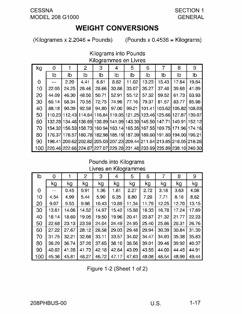
WEIGHT CONVERSIONS
Figure 1-2 (Sheet 1 of 2)
208PHBUS-00
SECTION 1 CESSNAGENERAL MODEL 208 G1000
U.S.1-18
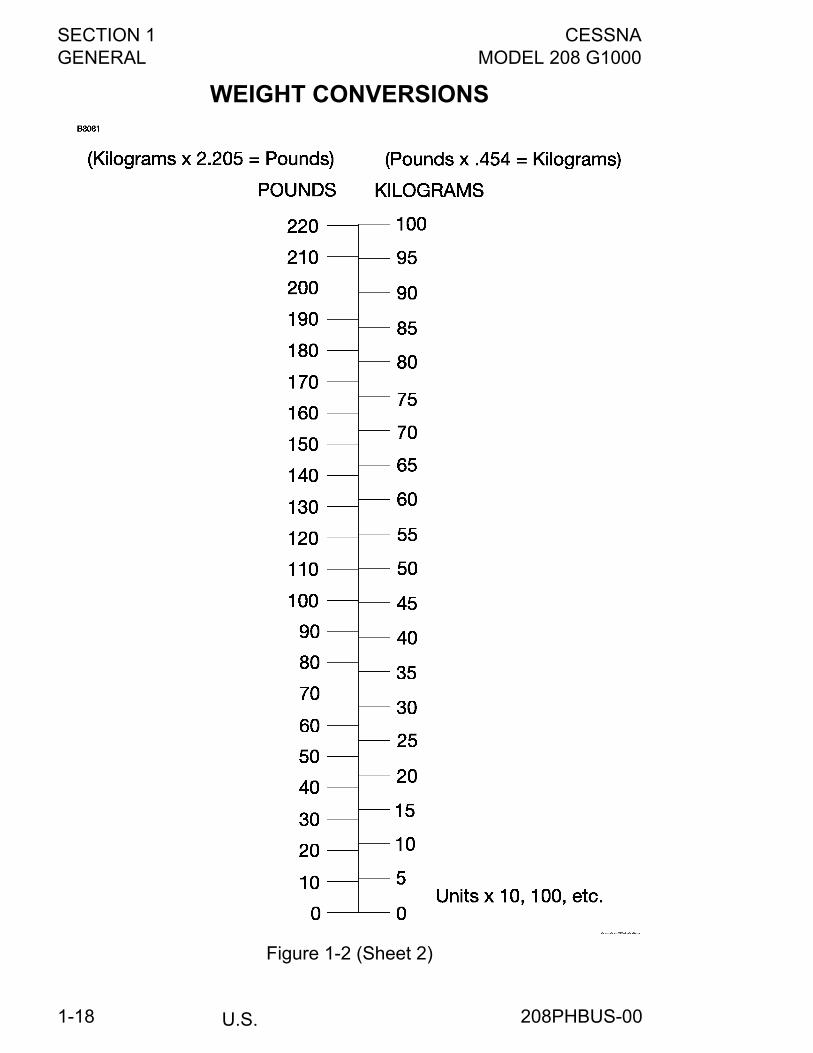
WEIGHT CONVERSIONS
Figure 1-2 (Sheet 2)
208PHBUS-00
CESSNA SECTION 1MODEL 208 G1000 GENERAL
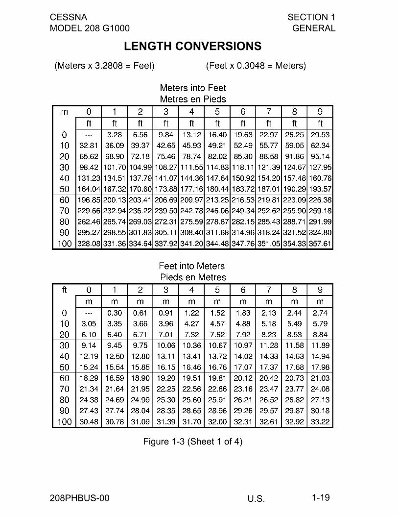
U.S. 1-19
LENGTH CONVERSIONS
Figure 1-3 (Sheet 1 of 4)
208PHBUS-00
SECTION 1 CESSNAGENERAL MODEL 208 G1000
U.S.1-20
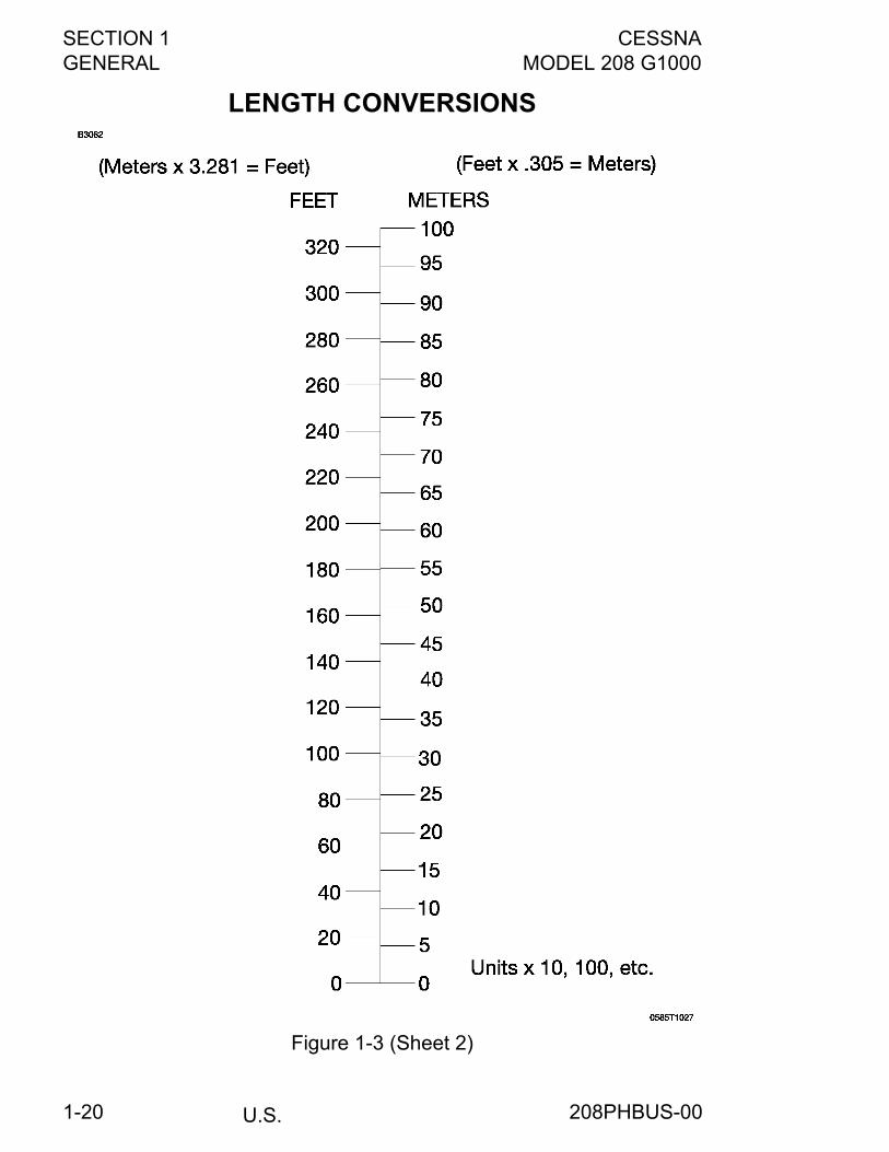
LENGTH CONVERSIONS
Figure 1-3 (Sheet 2)
208PHBUS-00
CESSNA SECTION 1MODEL 208 G1000 GENERAL
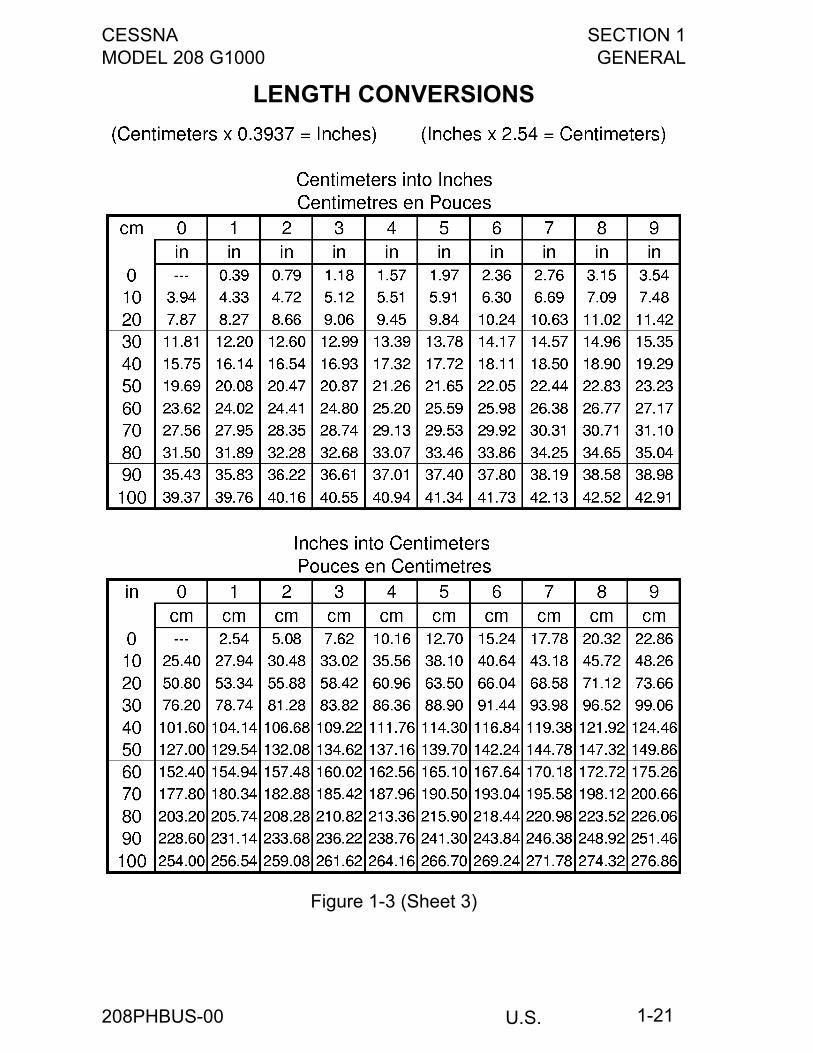
U.S. 1-21
LENGTH CONVERSIONS
Figure 1-3 (Sheet 3)
208PHBUS-00
SECTION 1 CESSNAGENERAL MODEL 208 G1000
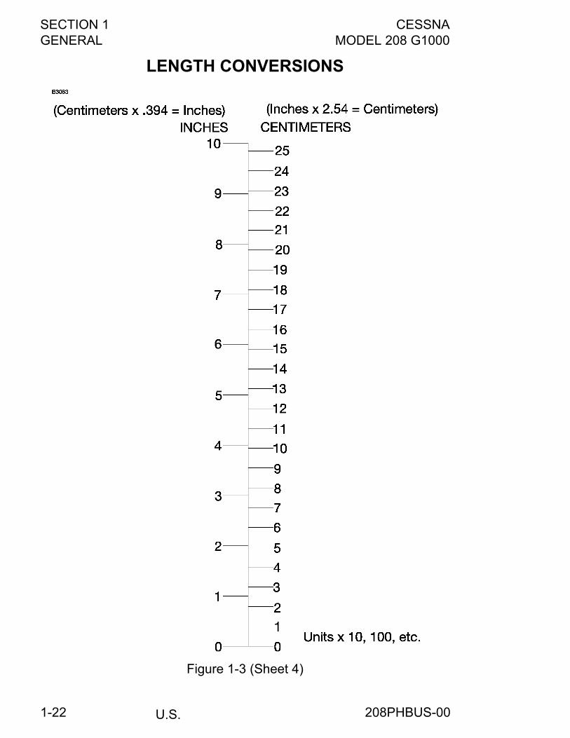
U.S.1-22
LENGTH CONVERSIONS
Figure 1-3 (Sheet 4)
208PHBUS-00
CESSNA SECTION 1MODEL 208 G1000 GENERAL
U.S. 1-23
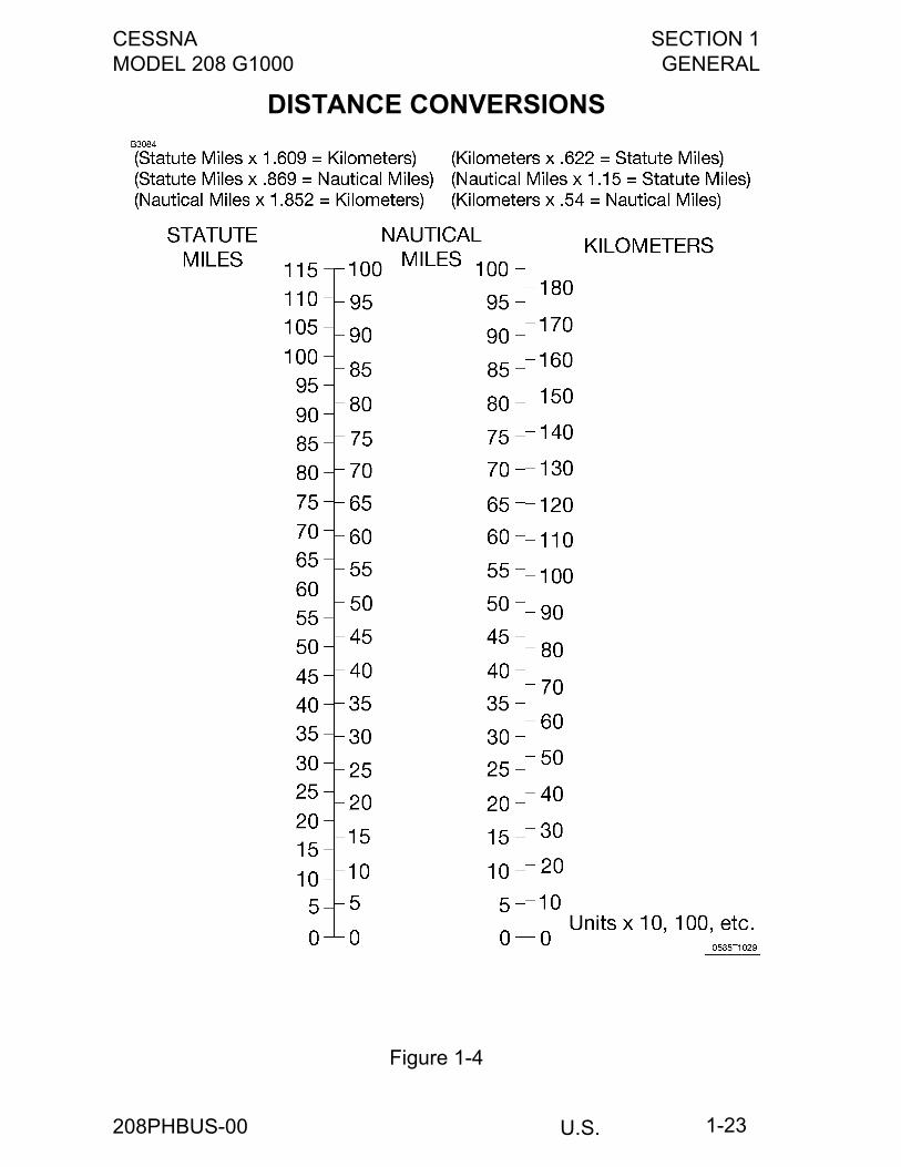
DISTANCE CONVERSIONS
Figure 1-4
208PHBUS-00
SECTION 1 CESSNAGENERAL MODEL 208 G1000
U.S.1-24
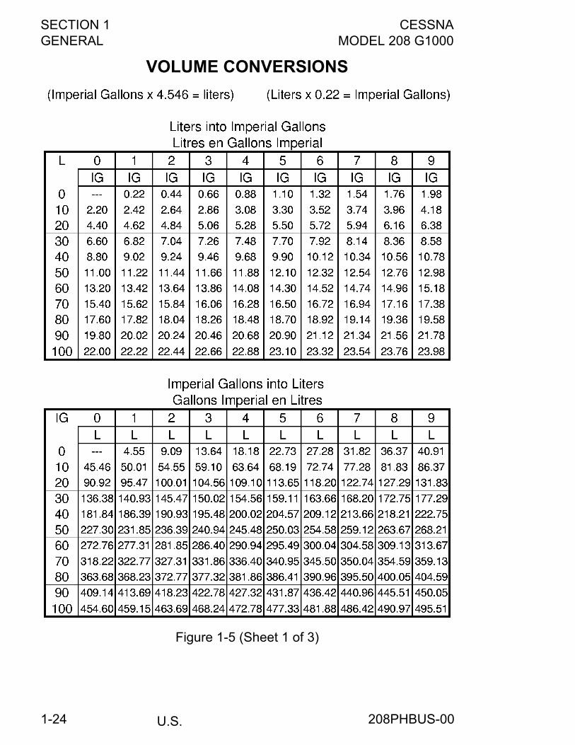
VOLUME CONVERSIONS
Figure 1-5 (Sheet 1 of 3)
208PHBUS-00
CESSNA SECTION 1MODEL 208 G1000 GENERAL
U.S. 1-25
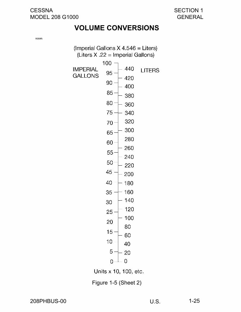
VOLUME CONVERSIONS
Figure 1-5 (Sheet 2)
208PHBUS-00
SECTION 1 CESSNAGENERAL MODEL 208 G1000
U.S.1-26
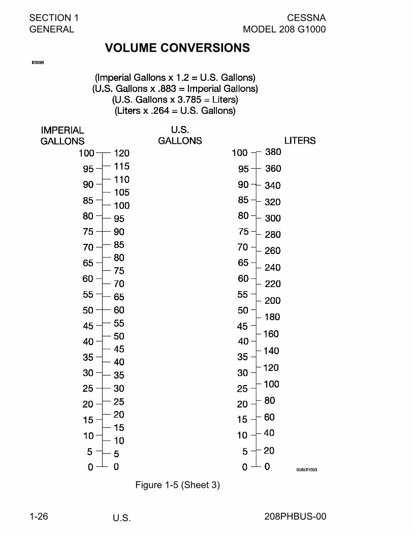
VOLUME CONVERSIONS
Figure 1-5 (Sheet 3)
208PHBUS-00
CESSNA SECTION 1MODEL 208 G1000 GENERAL
U.S. 1-27
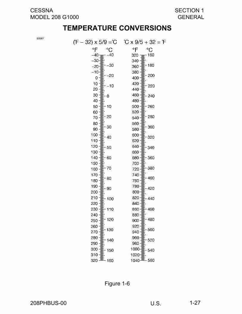
TEMPERATURE CONVERSIONS
Figure 1-6
208PHBUS-00
SECTION 1 CESSNAGENERAL MODEL 208 G1000
U.S.1-28
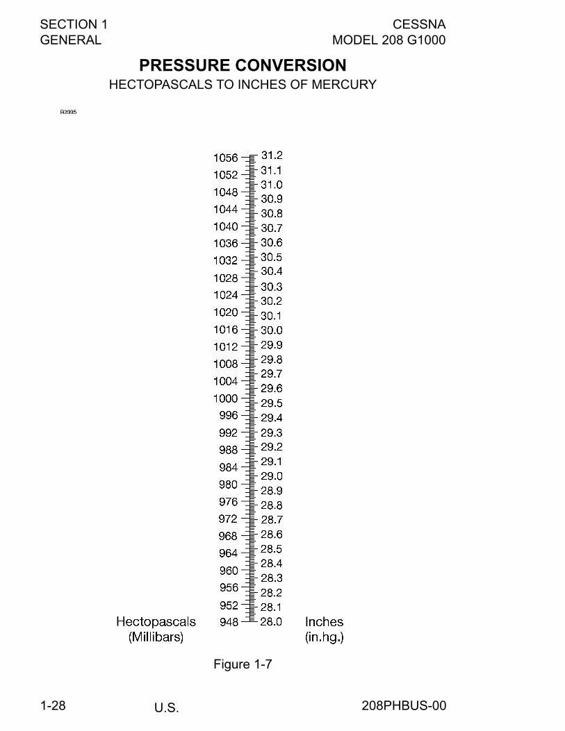
PRESSURE CONVERSIONHECTOPASCALS TO INCHES OF MERCURY
Figure 1-7
208PHBUS-00
CESSNA SECTION 2MODEL 208 G1000 LIMITATIONS
U.S.FAA APPROVED
2-1
LIMITATIONS
TABLE OF CONTENTSPage
Introduction . . . . . . . . . . . . . . . . . . . . . . . . . . . . . . . . . . . . . . . . . . . .2-3Airspeed Limitations . . . . . . . . . . . . . . . . . . . . . . . . . . . . . . . . . . . . .2-4Airspeed Indicator Markings . . . . . . . . . . . . . . . . . . . . . . . . . . . . . . .2-5Power Plant Limitations . . . . . . . . . . . . . . . . . . . . . . . . . . . . . . . . . . .2-6Power Plant Instrument Markings . . . . . . . . . . . . . . . . . . . . . . . . . .2-10Miscellaneous Instrument Markings . . . . . . . . . . . . . . . . . . . . . . . . 2-11Preflight . . . . . . . . . . . . . . . . . . . . . . . . . . . . . . . . . . . . . . . . . . . . . .2-12Visual and Tactile Check . . . . . . . . . . . . . . . . . . . . . . . . . . . . . . . . .2-12Weight Limits . . . . . . . . . . . . . . . . . . . . . . . . . . . . . . . . . . . . . . . . . .2-12Center of Gravity Limits . . . . . . . . . . . . . . . . . . . . . . . . . . . . . . . . . .2-13Maneuver Limits . . . . . . . . . . . . . . . . . . . . . . . . . . . . . . . . . . . . . . .2-13Flight Load Factor Limits . . . . . . . . . . . . . . . . . . . . . . . . . . . . . . . . .2-14Flight Crew Limits . . . . . . . . . . . . . . . . . . . . . . . . . . . . . . . . . . . . . .2-14Kinds of Operations Equipment List . . . . . . . . . . . . . . . . . . . . . . . .2-14Fuel Limitations . . . . . . . . . . . . . . . . . . . . . . . . . . . . . . . . . . . . . . . .2-24Maximum Operating Altitude Limit . . . . . . . . . . . . . . . . . . . . . . . . . .2-27Outside Air Temperature Limits . . . . . . . . . . . . . . . . . . . . . . . . . . . .2-27Maximum Passenger Seating Limits . . . . . . . . . . . . . . . . . . . . . . . .2-27Other Limitations . . . . . . . . . . . . . . . . . . . . . . . . . . . . . . . . . . . . . . .2-28
Flap Limitations . . . . . . . . . . . . . . . . . . . . . . . . . . . . . . . . . . . . . .2-28Standby Electric System . . . . . . . . . . . . . . . . . . . . . . . . . . . . . . .2-28
Type II, Type III or Type IV Anti-ice Fluid Takeoff Limitations . . . . .2-28Flap Limitations . . . . . . . . . . . . . . . . . . . . . . . . . . . . . . . . . . . . . .2-28Airspeed Limitations . . . . . . . . . . . . . . . . . . . . . . . . . . . . . . . . . .2-28
Flight in Known Icing Visual Cues . . . . . . . . . . . . . . . . . . . . . . . . . .2-29
(Continued Next Page)
208PHBUS-02
SECTION 2 CESSNALIMITATIONS MODEL 208 G1000
U.S.FAA APPROVED
2-2
Table of Contents (Continued)Page
G1000 Limitations . . . . . . . . . . . . . . . . . . . . . . . . . . . . . . . . . . . . . 2-30Operational Approvals . . . . . . . . . . . . . . . . . . . . . . . . . . . . . . . . . . 2-31Garmin GFC-700 AFCS . . . . . . . . . . . . . . . . . . . . . . . . . . . . . . . . . 2-32L3 Communications WX 500 Stormscope . . . . . . . . . . . . . . . . . . . 2-33Traffic Advisory System (TAS) . . . . . . . . . . . . . . . . . . . . . . . . . . . . 2-33Terrain Awareness and Warning System (TAWS-B) . . . . . . . . . . . 2-33Optional Equipment User’s Guide . . . . . . . . . . . . . . . . . . . . . . . . . 2-33Placards . . . . . . . . . . . . . . . . . . . . . . . . . . . . . . . . . . . . . . . . . . . . . 2-34
208PHBUS-02
CESSNA SECTION 2MODEL 208 G1000 LIMITATIONS
U.S.FAA APPROVED
2-3
INTRODUCTIONSection 2 includes operating limitations, instrument markings, andbasic placards necessary for the safe operation of the airplane, itsengine, standard/non-standard systems and standard/non-standardequipment.
WARNING
The limitations included in this section and inSection 9 have been approved by the FederalAviation Administration. Observance of theseoperating limitations is required by federal aviationregulations.
NOTE
• Operation in countries other than the United States mayrequire observance of other limitations, procedures orperformance data.
• Refer to Section 9 of this POH/AFM for amendedoperating limitations, procedures, performance data andother necessary information for supplemental systems.
• The airspeeds listed in Airspeed Limitations chart, andAirspeed Indicator Markings chart are based onAirspeed Calibration data shown in Section 5 with thenormal static source. If the alternate static source isbeing used, ample margins should be observed to allowfor the airspeed calibration variations between thenormal and alternate static sources as shown in Section5.
Your Cessna is certificated under FAA Type Certificate No. A37CE asCessna Model No. 208.
208PHBUS-00
SECTION 2 CESSNALIMITATIONS MODEL 208 G1000
U.S.FAA APPROVED
2-4
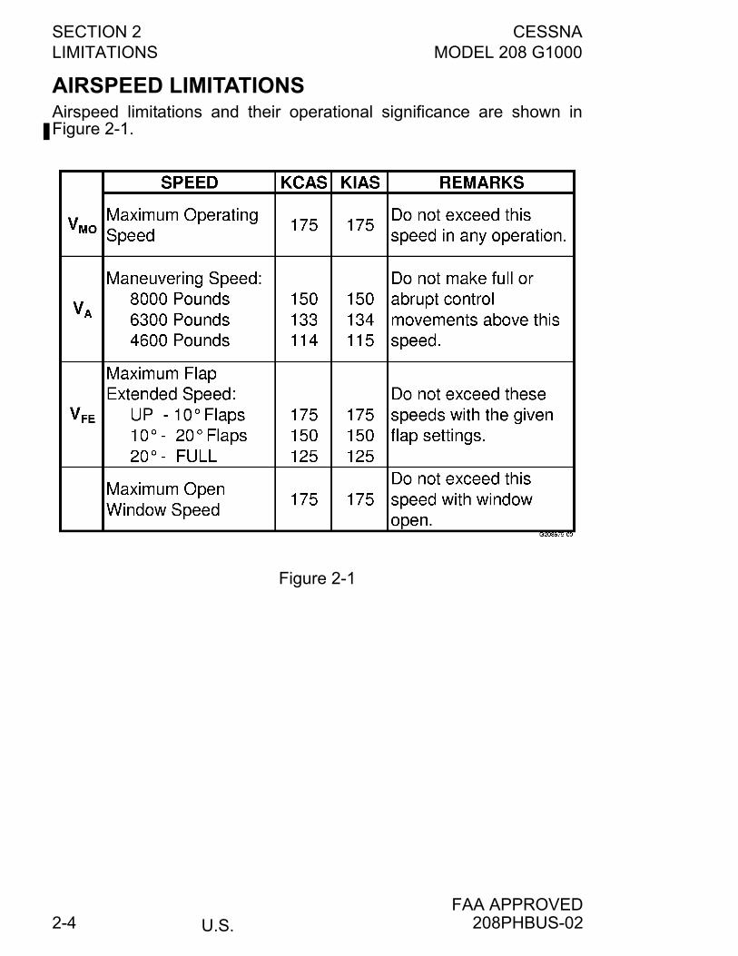
AIRSPEED LIMITATIONSAirspeed limitations and their operational significance are shown inFigure 2-1.
Figure 2-1
208PHBUS-02
CESSNA SECTION 2MODEL 208 G1000 LIMITATIONS
U.S.FAA APPROVED
2-5
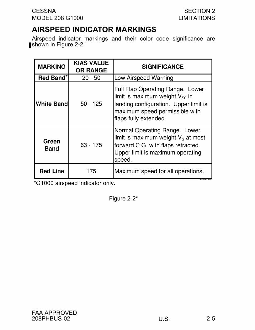
AIRSPEED INDICATOR MARKINGSAirspeed indicator markings and their color code significance areshown in Figure 2-2.
Figure 2-2*
208PHBUS-02
SECTION 2 CESSNALIMITATIONS MODEL 208 G1000
U.S.FAA APPROVED
2-6
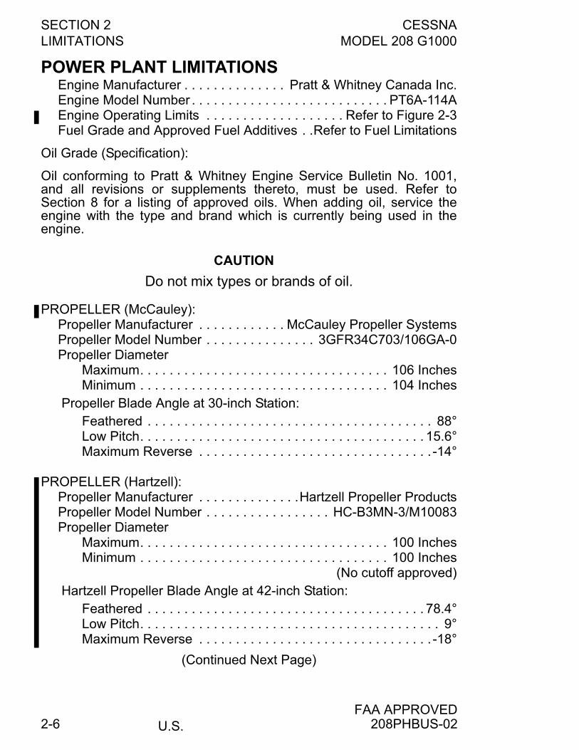
POWER PLANT LIMITATIONSEngine Manufacturer . . . . . . . . . . . . . . Pratt & Whitney Canada Inc.Engine Model Number . . . . . . . . . . . . . . . . . . . . . . . . . . . PT6A-114AEngine Operating Limits . . . . . . . . . . . . . . . . . . . Refer to Figure 2-3Fuel Grade and Approved Fuel Additives . .Refer to Fuel Limitations
Oil Grade (Specification):
Oil conforming to Pratt & Whitney Engine Service Bulletin No. 1001,and all revisions or supplements thereto, must be used. Refer toSection 8 for a listing of approved oils. When adding oil, service theengine with the type and brand which is currently being used in theengine.
CAUTION
Do not mix types or brands of oil.
PROPELLER (McCauley):Propeller Manufacturer . . . . . . . . . . . . McCauley Propeller SystemsPropeller Model Number . . . . . . . . . . . . . . . 3GFR34C703/106GA-0Propeller Diameter
Maximum. . . . . . . . . . . . . . . . . . . . . . . . . . . . . . . . . . 106 InchesMinimum . . . . . . . . . . . . . . . . . . . . . . . . . . . . . . . . . . 104 Inches
Propeller Blade Angle at 30-inch Station:Feathered . . . . . . . . . . . . . . . . . . . . . . . . . . . . . . . . . . . . . . . 88°Low Pitch. . . . . . . . . . . . . . . . . . . . . . . . . . . . . . . . . . . . . . . 15.6°Maximum Reverse . . . . . . . . . . . . . . . . . . . . . . . . . . . . . . . . -14°
PROPELLER (Hartzell):Propeller Manufacturer . . . . . . . . . . . . . .Hartzell Propeller ProductsPropeller Model Number . . . . . . . . . . . . . . . . . HC-B3MN-3/M10083Propeller Diameter
Maximum. . . . . . . . . . . . . . . . . . . . . . . . . . . . . . . . . . 100 InchesMinimum . . . . . . . . . . . . . . . . . . . . . . . . . . . . . . . . . . 100 Inches
(No cutoff approved)Hartzell Propeller Blade Angle at 42-inch Station:
Feathered . . . . . . . . . . . . . . . . . . . . . . . . . . . . . . . . . . . . . . 78.4°Low Pitch. . . . . . . . . . . . . . . . . . . . . . . . . . . . . . . . . . . . . . . . . 9°Maximum Reverse . . . . . . . . . . . . . . . . . . . . . . . . . . . . . . . . -18°
(Continued Next Page)
208PHBUS-02
CESSNA SECTION 2MODEL 208 G1000 LIMITATIONS
U.S.FAA APPROVED
2-7
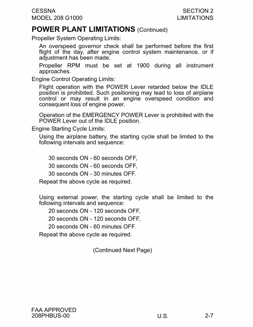
POWER PLANT LIMITATIONS (Continued)
Propeller System Operating Limits:An overspeed governor check shall be performed before the firstflight of the day, after engine control system maintenance, or ifadjustment has been made.Propeller RPM must be set at 1900 during all instrumentapproaches.
Engine Control Operating Limits:Flight operation with the POWER Lever retarded below the IDLEposition is prohibited. Such positioning may lead to loss of airplanecontrol or may result in an engine overspeed condition andconsequent loss of engine power.
Operation of the EMERGENCY POWER Lever is prohibited with thePOWER Lever out of the IDLE position.
Engine Starting Cycle Limits:Using the airplane battery, the starting cycle shall be limited to thefollowing intervals and sequence:
30 seconds ON - 60 seconds OFF,30 seconds ON - 60 seconds OFF,30 seconds ON - 30 minutes OFF.
Repeat the above cycle as required.
Using external power, the starting cycle shall be limited to thefollowing intervals and sequence:
20 seconds ON - 120 seconds OFF,20 seconds ON - 120 seconds OFF,20 seconds ON - 60 minutes OFF.
Repeat the above cycle as required.
(Continued Next Page)
208PHBUS-00

SECTION 2 CESSNALIMITATIONS MODEL 208 G1000
U.S.FAA APPROVED
2-8
POWER PLANT LIMITATIONS (Continued)
ENGINE OPERATING LIMITS
Figure 2-3 (Sheet 1 of 2)
208PHBUS-00
CESSNA SECTION 2MODEL 208 G1000 LIMITATIONS
U.S.FAA APPROVED
2-9
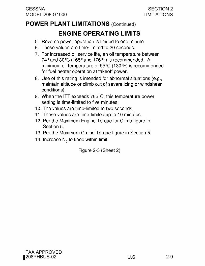
POWER PLANT LIMITATIONS (Continued)
ENGINE OPERATING LIMITS
Figure 2-3 (Sheet 2)
208PHBUS-02
SECTION 2 CESSNALIMITATIONS MODEL 208 G1000
U.S.FAA APPROVED
2-10
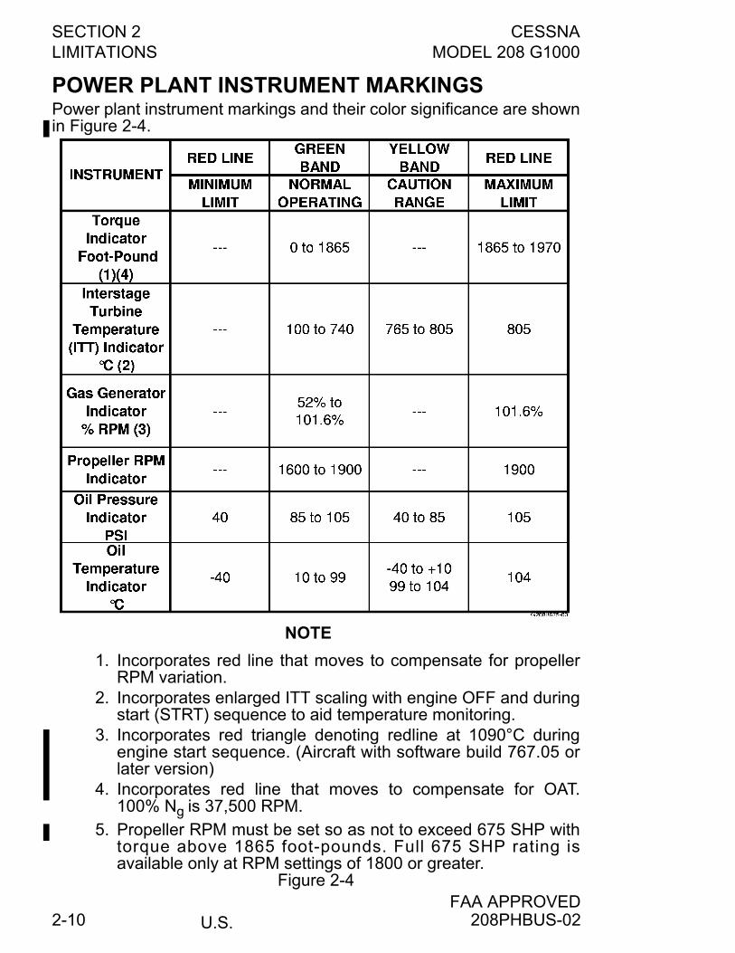
POWER PLANT INSTRUMENT MARKINGSPower plant instrument markings and their color significance are shownin Figure 2-4.
NOTE
1. Incorporates red line that moves to compensate for propellerRPM variation.
2. Incorporates enlarged ITT scaling with engine OFF and duringstart (STRT) sequence to aid temperature monitoring.
3. Incorporates red triangle denoting redline at 1090°C duringengine start sequence. (Aircraft with software build 767.05 orlater version)
4. Incorporates red line that moves to compensate for OAT.100% Ng is 37,500 RPM.
5. Propeller RPM must be set so as not to exceed 675 SHP withtorque above 1865 foot-pounds. Full 675 SHP rating isavailable only at RPM settings of 1800 or greater.
Figure 2-4
208PHBUS-02
CESSNA SECTION 2MODEL 208 G1000 LIMITATIONS
U.S.FAA APPROVED
2-11
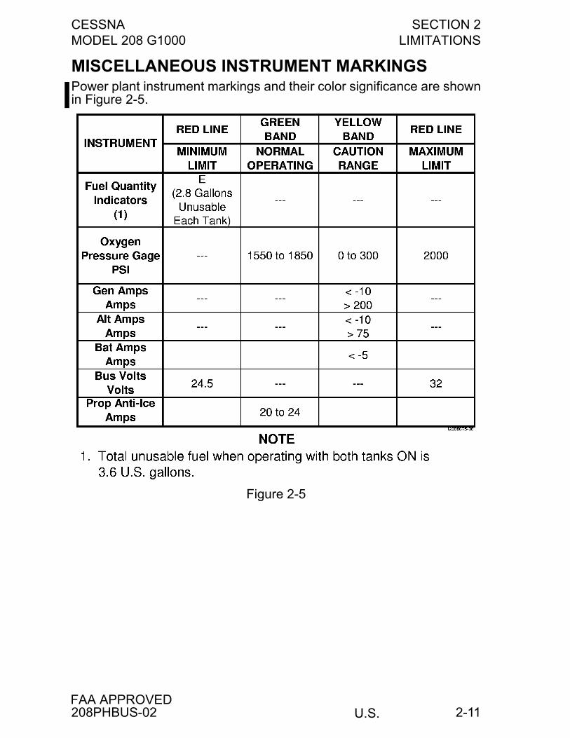
MISCELLANEOUS INSTRUMENT MARKINGSPower plant instrument markings and their color significance are shownin Figure 2-5.
Figure 2-5
208PHBUS-02
SECTION 2 CESSNALIMITATIONS MODEL 208 G1000
U.S.FAA APPROVED
2-12
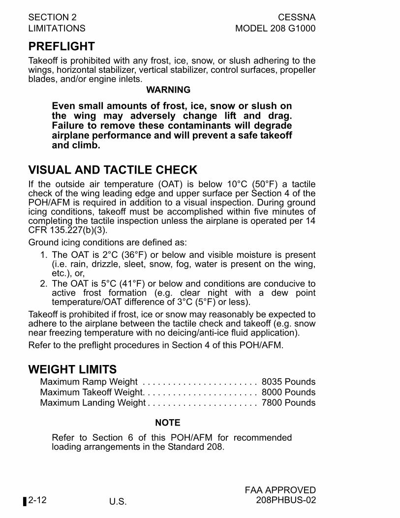
PREFLIGHTTakeoff is prohibited with any frost, ice, snow, or slush adhering to thewings, horizontal stabilizer, vertical stabilizer, control surfaces, propellerblades, and/or engine inlets.
WARNING
Even small amounts of frost, ice, snow or slush onthe wing may adversely change lift and drag.Failure to remove these contaminants will degradeairplane performance and will prevent a safe takeoffand climb.
VISUAL AND TACTILE CHECKIf the outside air temperature (OAT) is below 10°C (50°F) a tactilecheck of the wing leading edge and upper surface per Section 4 of thePOH/AFM is required in addition to a visual inspection. During groundicing conditions, takeoff must be accomplished within five minutes ofcompleting the tactile inspection unless the airplane is operated per 14CFR 135.227(b)(3).Ground icing conditions are defined as:
1. The OAT is 2°C (36°F) or below and visible moisture is present(i.e. rain, drizzle, sleet, snow, fog, water is present on the wing,etc.), or,
2. The OAT is 5°C (41°F) or below and conditions are conducive toactive frost formation (e.g. clear night with a dew pointtemperature/OAT difference of 3°C (5°F) or less).
Takeoff is prohibited if frost, ice or snow may reasonably be expected toadhere to the airplane between the tactile check and takeoff (e.g. snownear freezing temperature with no deicing/anti-ice fluid application).Refer to the preflight procedures in Section 4 of this POH/AFM.
WEIGHT LIMITSMaximum Ramp Weight . . . . . . . . . . . . . . . . . . . . . . . 8035 PoundsMaximum Takeoff Weight. . . . . . . . . . . . . . . . . . . . . . . 8000 PoundsMaximum Landing Weight . . . . . . . . . . . . . . . . . . . . . . 7800 Pounds
NOTE
Refer to Section 6 of this POH/AFM for recommendedloading arrangements in the Standard 208.
208PHBUS-02
CESSNA SECTION 2MODEL 208 G1000 LIMITATIONS
U.S.FAA APPROVED
2-13
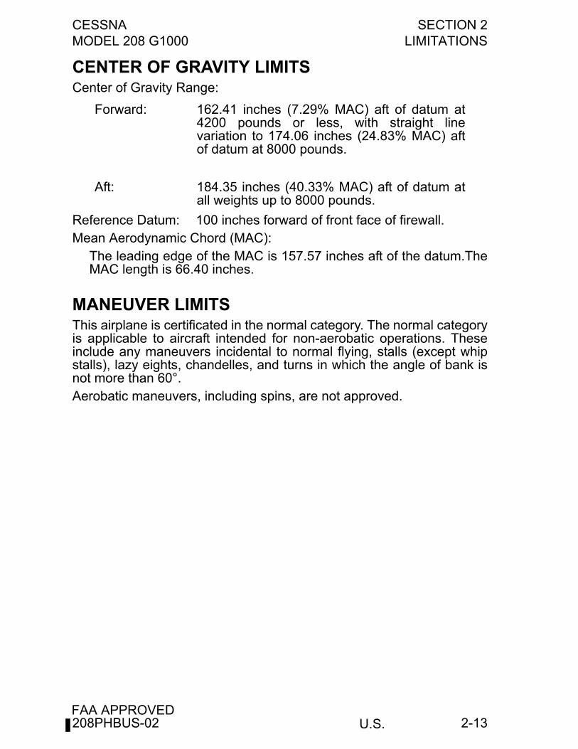
CENTER OF GRAVITY LIMITSCenter of Gravity Range:
Reference Datum: 100 inches forward of front face of firewall.Mean Aerodynamic Chord (MAC):
The leading edge of the MAC is 157.57 inches aft of the datum.TheMAC length is 66.40 inches.
MANEUVER LIMITSThis airplane is certificated in the normal category. The normal categoryis applicable to aircraft intended for non-aerobatic operations. Theseinclude any maneuvers incidental to normal flying, stalls (except whipstalls), lazy eights, chandelles, and turns in which the angle of bank isnot more than 60°.Aerobatic maneuvers, including spins, are not approved.
Forward: 162.41 inches (7.29% MAC) aft of datum at4200 pounds or less, with straight linevariation to 174.06 inches (24.83% MAC) aftof datum at 8000 pounds.
Aft: 184.35 inches (40.33% MAC) aft of datum atall weights up to 8000 pounds.
208PHBUS-02
SECTION 2 CESSNALIMITATIONS MODEL 208 G1000
U.S.FAA APPROVED
2-14
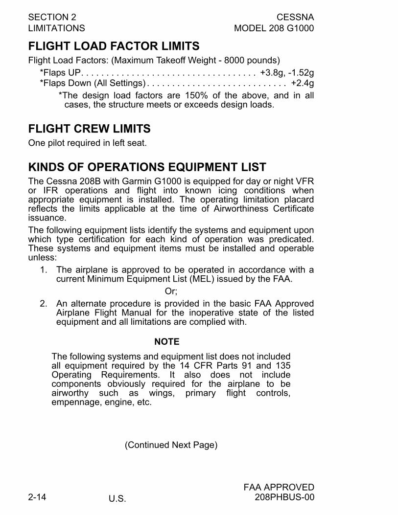
FLIGHT LOAD FACTOR LIMITSFlight Load Factors: (Maximum Takeoff Weight - 8000 pounds)
*Flaps UP. . . . . . . . . . . . . . . . . . . . . . . . . . . . . . . . . . . +3.8g, -1.52g*Flaps Down (All Settings) . . . . . . . . . . . . . . . . . . . . . . . . . . . . +2.4g
*The design load factors are 150% of the above, and in allcases, the structure meets or exceeds design loads.
FLIGHT CREW LIMITSOne pilot required in left seat.
KINDS OF OPERATIONS EQUIPMENT LISTThe Cessna 208B with Garmin G1000 is equipped for day or night VFRor IFR operations and flight into known icing conditions whenappropriate equipment is installed. The operating limitation placardreflects the limits applicable at the time of Airworthiness Certificateissuance.The following equipment lists identify the systems and equipment uponwhich type certification for each kind of operation was predicated.These systems and equipment items must be installed and operableunless:
1. The airplane is approved to be operated in accordance with acurrent Minimum Equipment List (MEL) issued by the FAA.
Or;2. An alternate procedure is provided in the basic FAA Approved
Airplane Flight Manual for the inoperative state of the listedequipment and all limitations are complied with.
NOTE
The following systems and equipment list does not includedall equipment required by the 14 CFR Parts 91 and 135Operating Requirements. It also does not includecomponents obviously required for the airplane to beairworthy such as wings, primary flight controls,empennage, engine, etc.
(Continued Next Page)
208PHBUS-00
CESSNA SECTION 2MODEL 208 G1000 LIMITATIONS
U.S.FAA APPROVED
2-15
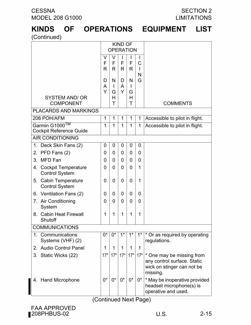
KINDS OF OPERATIONS EQUIPMENT LIST(Continued)
(Continued Next Page)
KIND OF OPERATION
SYSTEM AND/ OR COMPONENT
VFR
DAY
VFR
NIGHT
IFR
DAY
IFR
NIGHT
ICING
COMMENTS
PLACARDS AND MARKINGS
208 POH/AFM 1 1 1 1 1 Accessible to pilot in flight.
Garmin G1000TM
Cockpit Reference Guide1 1 1 1 1 Accessible to pilot in flight.
AIR CONDITIONING
1. Deck Skin Fans (2) 0 0 0 0 0
2. PFD Fans (2) 0 0 0 0 0
3. MFD Fan 0 0 0 0 0
4. Cockpit TemperatureControl System
0 0 0 0 1
5. Cabin TemperatureControl System
0 0 0 0 1
6. Ventilation Fans (2) 0 0 0 0 0
7. Air ConditioningSystem
0 0 0 0 0
8. Cabin Heat FirewallShutoff
1 1 1 1 1
COMMUNICATIONS
1. CommunicationsSystems (VHF) (2)
0* 0* 1* 1* 1* * Or as required by operating regulations.
2. Audio Control Panel 1 1 1 1 1
3. Static Wicks (22) 17* 17* 17* 17* 17* * One may be missing from any control surface. Static wick on stinger can not be missing.
4. Hand Microphone 0* 0* 0* 0* 0* * May be inoperative provided headset microphone(s) is operative and used.
208PHBUS-02
SECTION 2 CESSNALIMITATIONS MODEL 208 G1000
U.S.FAA APPROVED
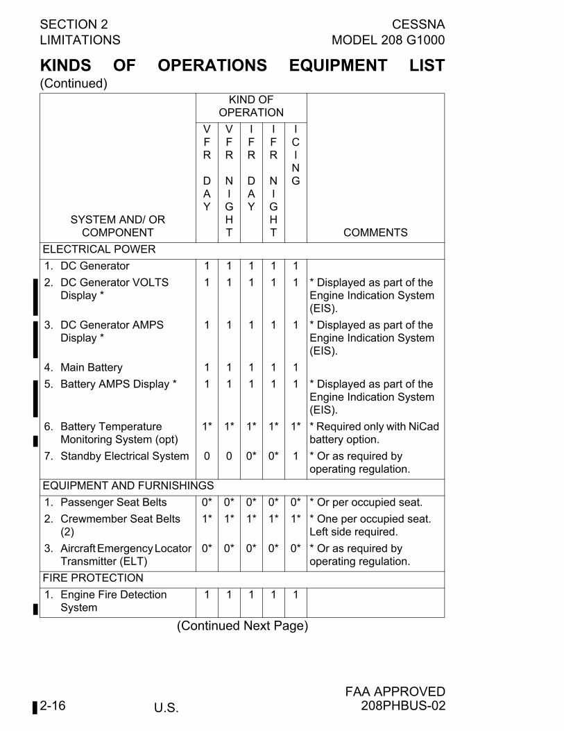
2-16
KINDS OF OPERATIONS EQUIPMENT LIST(Continued)
(Continued Next Page)
KIND OF OPERATION
SYSTEM AND/ OR COMPONENT
VFR
DAY
VFR
NIGHT
IFR
DAY
IFR
NIGHT
ICING
COMMENTS
ELECTRICAL POWER
1. DC Generator 1 1 1 1 1
2. DC Generator VOLTS Display *
1 1 1 1 1 * Displayed as part of the Engine Indication System (EIS).
3. DC Generator AMPS Display *
1 1 1 1 1 * Displayed as part of the Engine Indication System (EIS).
4. Main Battery 1 1 1 1 1
5. Battery AMPS Display * 1 1 1 1 1 * Displayed as part of the Engine Indication System (EIS).
6. Battery Temperature Monitoring System (opt)
1* 1* 1* 1* 1* * Required only with NiCad battery option.
7. Standby Electrical System 0 0 0* 0* 1 * Or as required byoperating regulation.
EQUIPMENT AND FURNISHINGS
1. Passenger Seat Belts 0* 0* 0* 0* 0* * Or per occupied seat.
2. Crewmember Seat Belts (2)
1* 1* 1* 1* 1* * One per occupied seat. Left side required.
3. Aircraft Emergency Locator Transmitter (ELT)
0* 0* 0* 0* 0* * Or as required by operating regulation.
FIRE PROTECTION
1. Engine Fire Detection System
1 1 1 1 1
208PHBUS-02
CESSNA SECTION 2MODEL 208 G1000 LIMITATIONS
U.S.FAA APPROVED
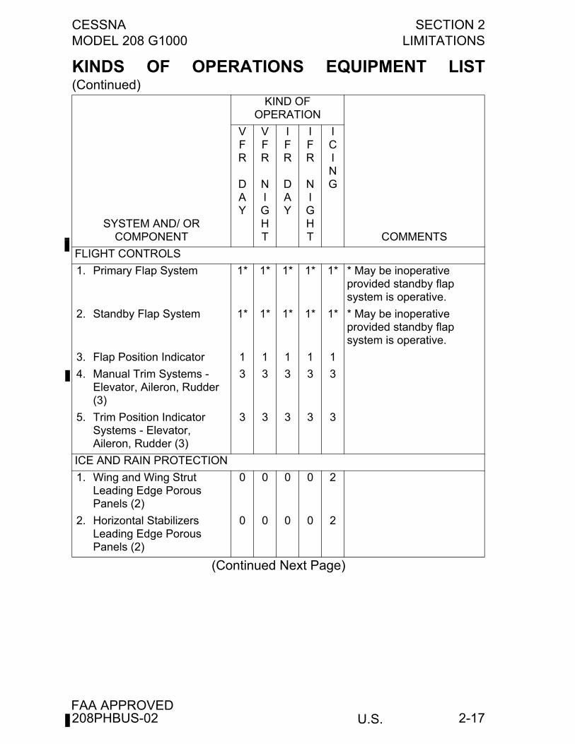
2-17
KINDS OF OPERATIONS EQUIPMENT LIST(Continued)
(Continued Next Page)
KIND OF OPERATION
SYSTEM AND/ OR COMPONENT
VFR
DAY
VFR
NIGHT
IFR
DAY
IFR
NIGHT
ICING
COMMENTS
FLIGHT CONTROLS
1. Primary Flap System 1* 1* 1* 1* 1* * May be inoperative provided standby flap system is operative.
2. Standby Flap System 1* 1* 1* 1* 1* * May be inoperative provided standby flap system is operative.
3. Flap Position Indicator 1 1 1 1 1
4. Manual Trim Systems - Elevator, Aileron, Rudder (3)
3 3 3 3 3
5. Trim Position Indicator Systems - Elevator, Aileron, Rudder (3)
3 3 3 3 3
ICE AND RAIN PROTECTION
1. Wing and Wing Strut Leading Edge Porous Panels (2)
0 0 0 0 2
2. Horizontal Stabilizers Leading Edge Porous Panels (2)
0 0 0 0 2
208PHBUS-02
SECTION 2 CESSNALIMITATIONS MODEL 208 G1000
U.S.FAA APPROVED
2-18
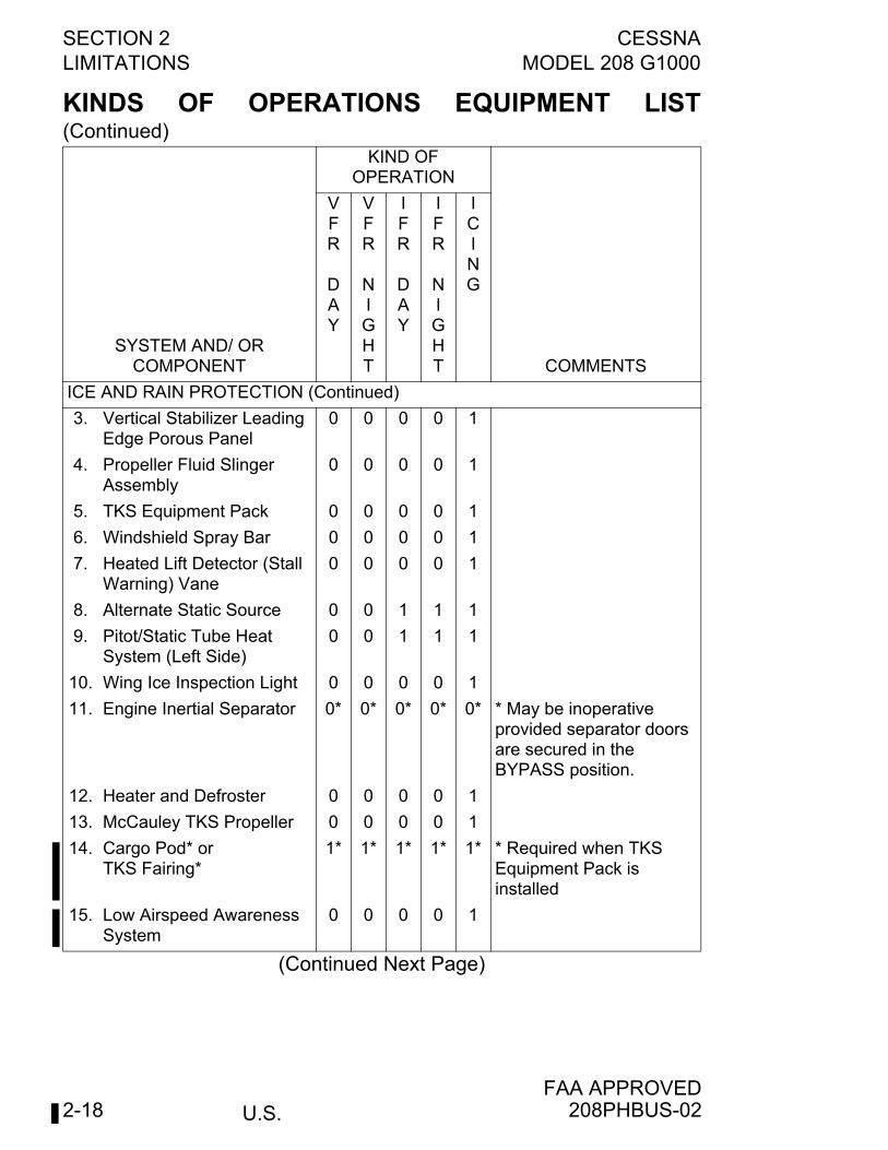
KINDS OF OPERATIONS EQUIPMENT LIST(Continued)
(Continued Next Page)
KIND OF OPERATION
SYSTEM AND/ OR COMPONENT
VFR
DAY
VFR
NIGHT
IFR
DAY
IFR
NIGHT
ICING
COMMENTS
ICE AND RAIN PROTECTION (Continued)
3. Vertical Stabilizer Leading Edge Porous Panel
0 0 0 0 1
4. Propeller Fluid Slinger Assembly
0 0 0 0 1
5. TKS Equipment Pack 0 0 0 0 1
6. Windshield Spray Bar 0 0 0 0 1
7. Heated Lift Detector (Stall Warning) Vane
0 0 0 0 1
8. Alternate Static Source 0 0 1 1 1
9. Pitot/Static Tube Heat System (Left Side)
0 0 1 1 1
10. Wing Ice Inspection Light 0 0 0 0 1
11. Engine Inertial Separator 0* 0* 0* 0* 0* * May be inoperative provided separator doors are secured in the BYPASS position.
12. Heater and Defroster 0 0 0 0 1
13. McCauley TKS Propeller 0 0 0 0 1
14. Cargo Pod* or TKS Fairing*
1* 1* 1* 1* 1* * Required when TKS Equipment Pack isinstalled
15. Low Airspeed Awareness System
0 0 0 0 1
208PHBUS-02
CESSNA SECTION 2MODEL 208 G1000 LIMITATIONS
U.S.FAA APPROVED
2-19
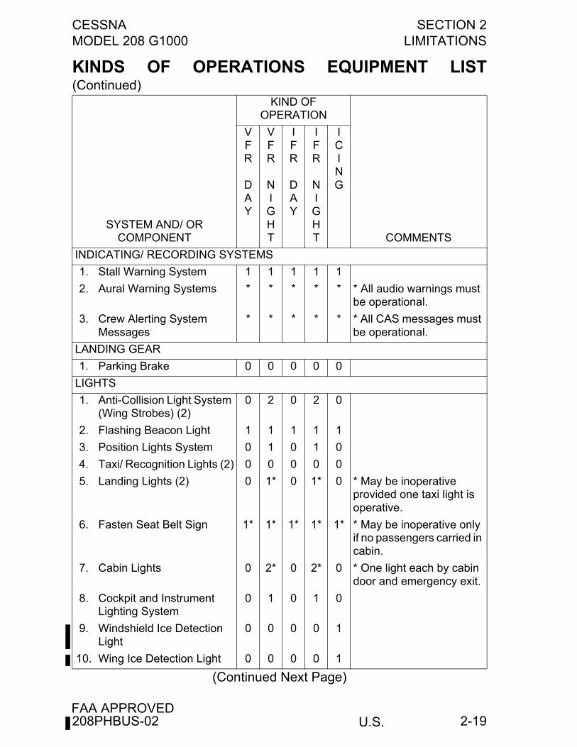
KINDS OF OPERATIONS EQUIPMENT LIST(Continued)
(Continued Next Page)
KIND OF OPERATION
SYSTEM AND/ ORCOMPONENT
VFR
DAY
VFR
NIGHT
IFR
DAY
IFR
NIGHT
ICING
COMMENTS
INDICATING/ RECORDING SYSTEMS
1. Stall Warning System 1 1 1 1 1
2. Aural Warning Systems * * * * * * All audio warnings must be operational.
3. Crew Alerting SystemMessages
* * * * * * All CAS messages must be operational.
LANDING GEAR
1. Parking Brake 0 0 0 0 0
LIGHTS
1. Anti-Collision Light System (Wing Strobes) (2)
0 2 0 2 0
2. Flashing Beacon Light 1 1 1 1 1
3. Position Lights System 0 1 0 1 0
4. Taxi/ Recognition Lights (2) 0 0 0 0 0
5. Landing Lights (2) 0 1* 0 1* 0 * May be inoperative provided one taxi light is operative.
6. Fasten Seat Belt Sign 1* 1* 1* 1* 1* * May be inoperative only if no passengers carried in cabin.
7. Cabin Lights 0 2* 0 2* 0 * One light each by cabin door and emergency exit.
8. Cockpit and Instrument Lighting System
0 1 0 1 0
9. Windshield Ice Detection Light
0 0 0 0 1
10. Wing Ice Detection Light 0 0 0 0 1
208PHBUS-02
SECTION 2 CESSNALIMITATIONS MODEL 208 G1000
U.S.FAA APPROVED
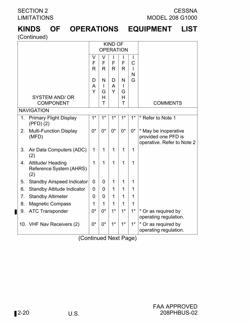
2-20
KINDS OF OPERATIONS EQUIPMENT LIST(Continued)
(Continued Next Page)
KIND OF OPERATION
SYSTEM AND/ OR COMPONENT
VFR
DAY
VFR
NIGHT
IFR
DAY
IFR
NIGHT
ICING
COMMENTS
NAVIGATION
1. Primary Flight Display (PFD) (2)
1* 1* 1* 1* 1* * Refer to Note 1
2. Multi-Function Display (MFD)
0* 0* 0* 0* 0* * May be inoperative provided one PFD is operative. Refer to Note 2
3. Air Data Computers (ADC) (2)
1 1 1 1 1
4. Attitude/ Heading Reference System (AHRS) (2)
1 1 1 1 1
5. Standby Airspeed Indicator 0 0 1 1 1
6. Standby Attitude Indicator 0 0 1 1 1
7. Standby Altimeter 0 0 1 1 1
8. Magnetic Compass 1 1 1 1 1
9. ATC Transponder 0* 0* 1* 1* 1* * Or as required by operating regulation.
10. VHF Nav Receivers (2) 0* 0* 1* 1* 1* * Or as required by operating regulation.
208PHBUS-02
CESSNA SECTION 2MODEL 208 G1000 LIMITATIONS
U.S.FAA APPROVED
2-21
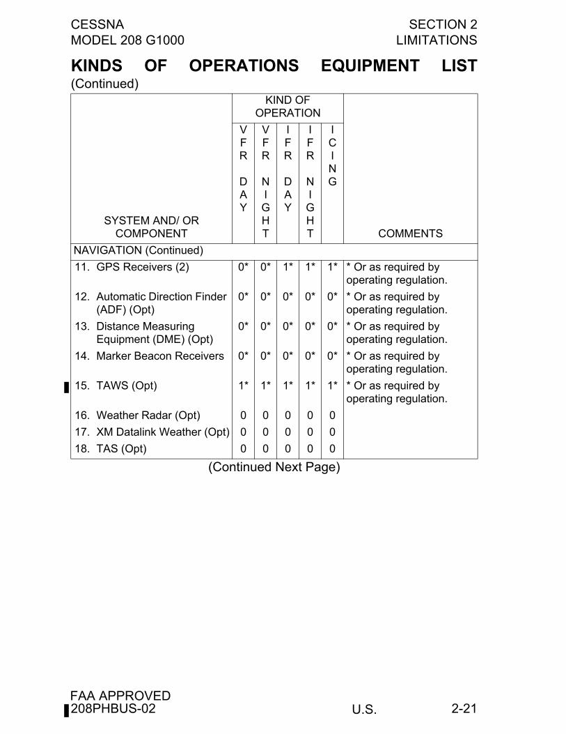
KINDS OF OPERATIONS EQUIPMENT LIST(Continued)
(Continued Next Page)
KIND OF OPERATION
SYSTEM AND/ OR COMPONENT
VFR
DAY
VFR
NIGHT
IFR
DAY
IFR
NIGHT
ICING
COMMENTS
NAVIGATION (Continued)
11. GPS Receivers (2) 0* 0* 1* 1* 1* * Or as required by operating regulation.
12. Automatic Direction Finder (ADF) (Opt)
0* 0* 0* 0* 0* * Or as required by operating regulation.
13. Distance Measuring Equipment (DME) (Opt)
0* 0* 0* 0* 0* * Or as required by operating regulation.
14. Marker Beacon Receivers 0* 0* 0* 0* 0* * Or as required by operating regulation.
15. TAWS (Opt) 1* 1* 1* 1* 1* * Or as required by operating regulation.
16. Weather Radar (Opt) 0 0 0 0 0
17. XM Datalink Weather (Opt) 0 0 0 0 0
18. TAS (Opt) 0 0 0 0 0
208PHBUS-02
SECTION 2 CESSNALIMITATIONS MODEL 208 G1000
U.S.FAA APPROVED
2-22
KINDS OF OPERATIONS EQUIPMENT LIST(Continued)
(Continued Next Page)
KIND OF OPERATION
SYSTEM AND/ OR COMPONENT
VFR
DAY
VFR
NIGHT
IFR
DAY
IFR
NIGHT
ICING
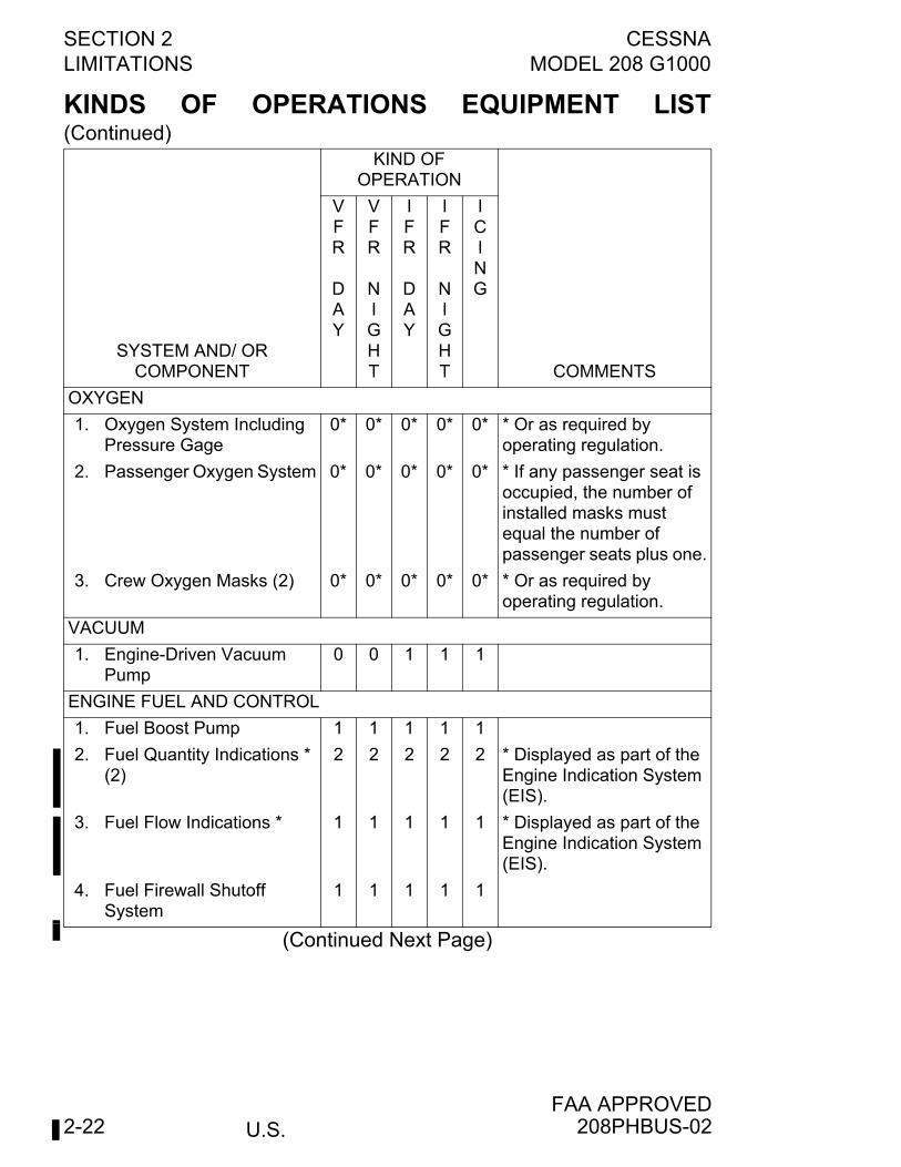
COMMENTS
OXYGEN
1. Oxygen System Including Pressure Gage
0* 0* 0* 0* 0* * Or as required by operating regulation.
2. Passenger Oxygen System 0* 0* 0* 0* 0* * If any passenger seat is occupied, the number of installed masks must equal the number of passenger seats plus one.
3. Crew Oxygen Masks (2) 0* 0* 0* 0* 0* * Or as required by operating regulation.
VACUUM
1. Engine-Driven Vacuum Pump
0 0 1 1 1
ENGINE FUEL AND CONTROL
1. Fuel Boost Pump 1 1 1 1 1
2. Fuel Quantity Indications * (2)
2 2 2 2 2 * Displayed as part of the Engine Indication System (EIS).
3. Fuel Flow Indications * 1 1 1 1 1 * Displayed as part of the Engine Indication System (EIS).
4. Fuel Firewall Shutoff System
1 1 1 1 1
208PHBUS-02
CESSNA SECTION 2MODEL 208 G1000 LIMITATIONS
U.S.FAA APPROVED
2-23
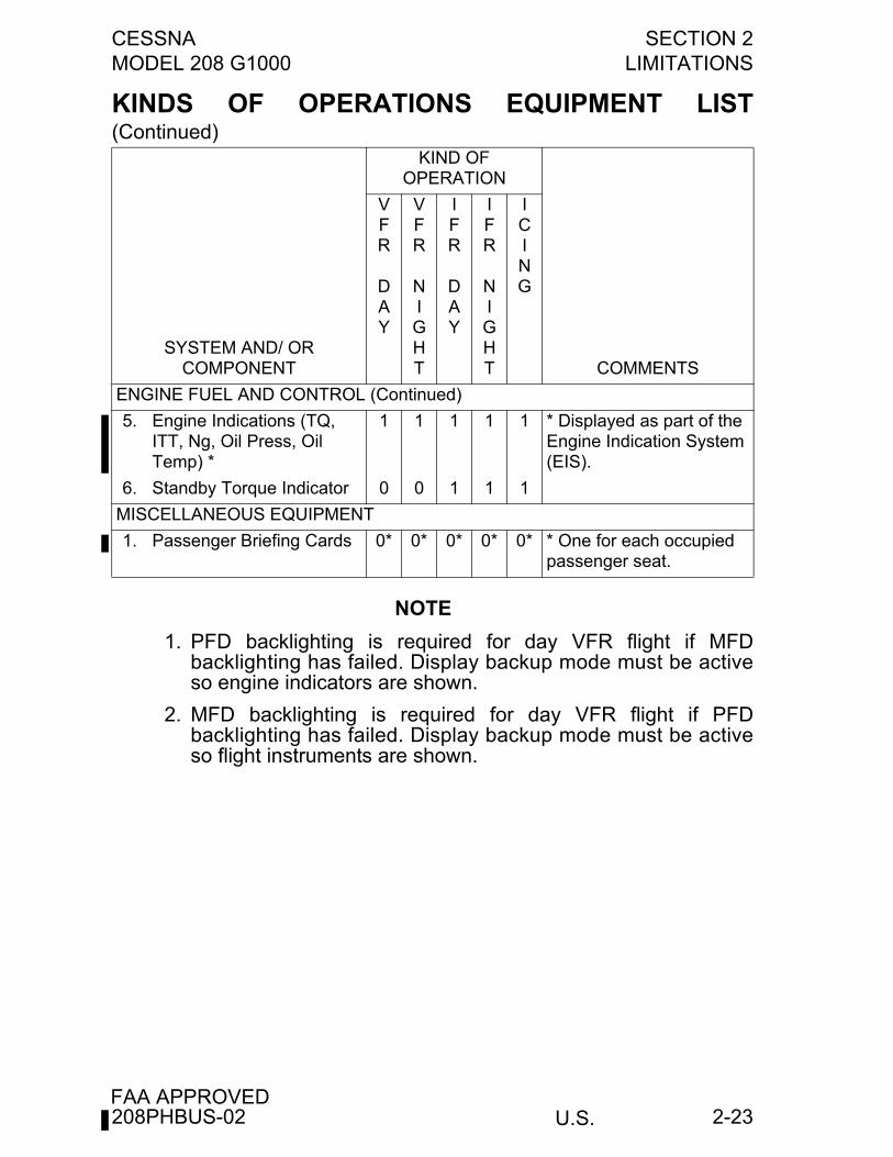
KINDS OF OPERATIONS EQUIPMENT LIST(Continued)
NOTE
1. PFD backlighting is required for day VFR flight if MFDbacklighting has failed. Display backup mode must be activeso engine indicators are shown.
2. MFD backlighting is required for day VFR flight if PFDbacklighting has failed. Display backup mode must be activeso flight instruments are shown.
KIND OF OPERATION
SYSTEM AND/ OR COMPONENT
VFR
DAY
VFR
NIGHT
IFR
DAY
IFR
NIGHT
ICING
COMMENTS
ENGINE FUEL AND CONTROL (Continued)
5. Engine Indications (TQ, ITT, Ng, Oil Press, Oil Temp) *
1 1 1 1 1 * Displayed as part of the Engine Indication System (EIS).
6. Standby Torque Indicator 0 0 1 1 1
MISCELLANEOUS EQUIPMENT
1. Passenger Briefing Cards 0* 0* 0* 0* 0* * One for each occupied passenger seat.
208PHBUS-02
SECTION 2 CESSNALIMITATIONS MODEL 208 G1000
U.S.FAA APPROVED
2-24
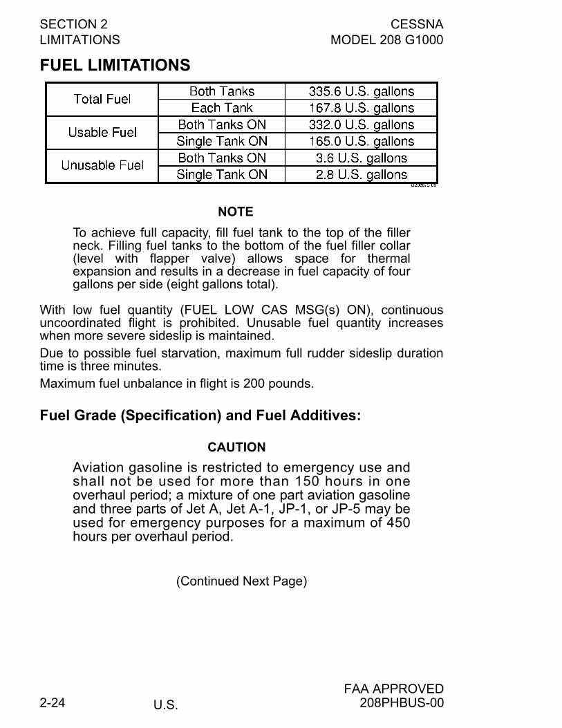
FUEL LIMITATIONS
NOTE
To achieve full capacity, fill fuel tank to the top of the fillerneck. Filling fuel tanks to the bottom of the fuel filler collar(level with flapper valve) allows space for thermalexpansion and results in a decrease in fuel capacity of fourgallons per side (eight gallons total).
With low fuel quantity (FUEL LOW CAS MSG(s) ON), continuousuncoordinated flight is prohibited. Unusable fuel quantity increaseswhen more severe sideslip is maintained.Due to possible fuel starvation, maximum full rudder sideslip durationtime is three minutes.Maximum fuel unbalance in flight is 200 pounds.
Fuel Grade (Specification) and Fuel Additives:
CAUTION
Aviation gasoline is restricted to emergency use andshall not be used for more than 150 hours in oneoverhaul period; a mixture of one part aviation gasolineand three parts of Jet A, Jet A-1, JP-1, or JP-5 may beused for emergency purposes for a maximum of 450hours per overhaul period.
(Continued Next Page)
208PHBUS-00
CESSNA SECTION 2MODEL 208 G1000 LIMITATIONS
U.S.FAA APPROVED
2-25
FUEL LIMITATIONS (Continued)
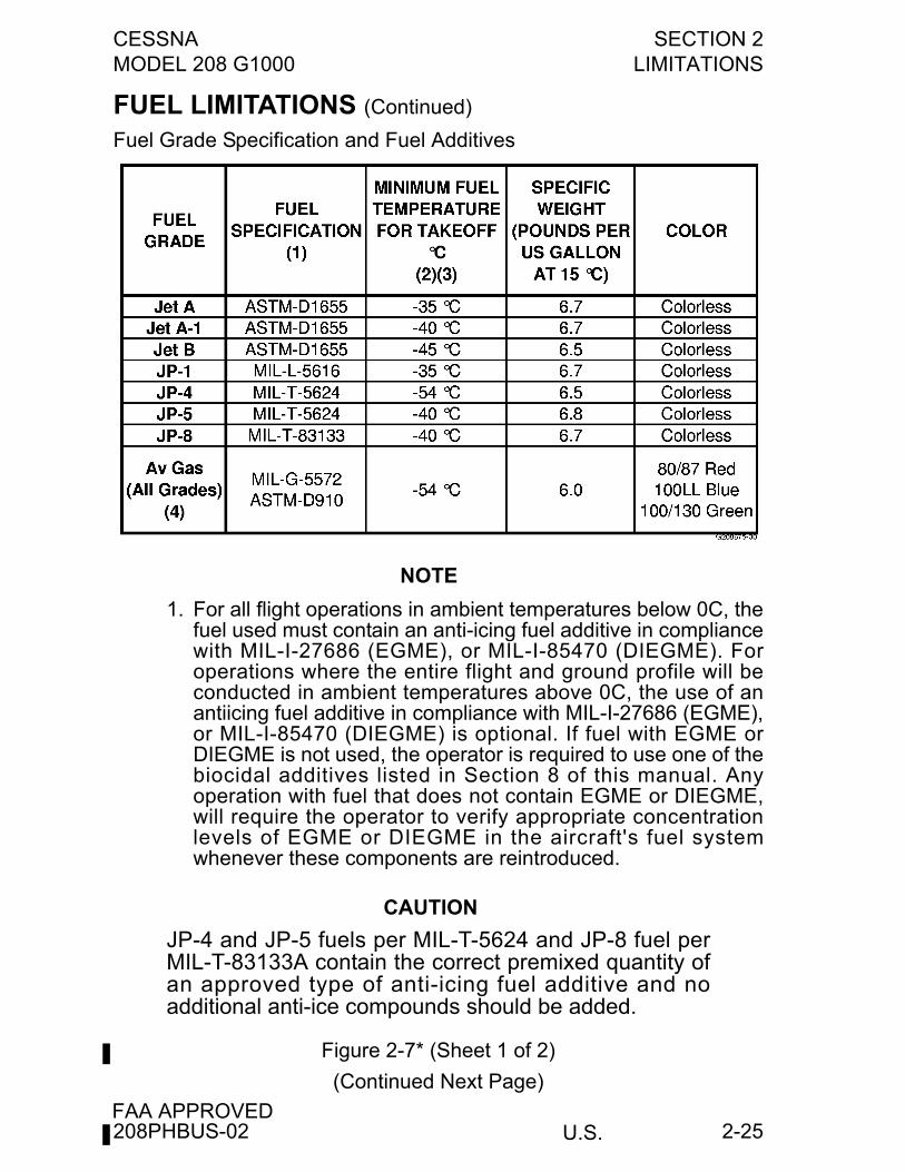
Fuel Grade Specification and Fuel Additives
NOTE
1. For all flight operations in ambient temperatures below 0C, thefuel used must contain an anti-icing fuel additive in compliancewith MIL-I-27686 (EGME), or MIL-I-85470 (DIEGME). Foroperations where the entire flight and ground profile will beconducted in ambient temperatures above 0C, the use of anantiicing fuel additive in compliance with MIL-I-27686 (EGME),or MIL-I-85470 (DIEGME) is optional. If fuel with EGME orDIEGME is not used, the operator is required to use one of thebiocidal additives listed in Section 8 of this manual. Anyoperation with fuel that does not contain EGME or DIEGME,will require the operator to verify appropriate concentrationlevels of EGME or DIEGME in the aircraft's fuel systemwhenever these components are reintroduced.
CAUTION
JP-4 and JP-5 fuels per MIL-T-5624 and JP-8 fuel perMIL-T-83133A contain the correct premixed quantity ofan approved type of anti-icing fuel additive and noadditional anti-ice compounds should be added.
Figure 2-7* (Sheet 1 of 2)
(Continued Next Page)
208PHBUS-02
SECTION 2 CESSNALIMITATIONS MODEL 208 G1000
U.S.FAA APPROVED
2-26
FUEL LIMITATIONS (Continued)
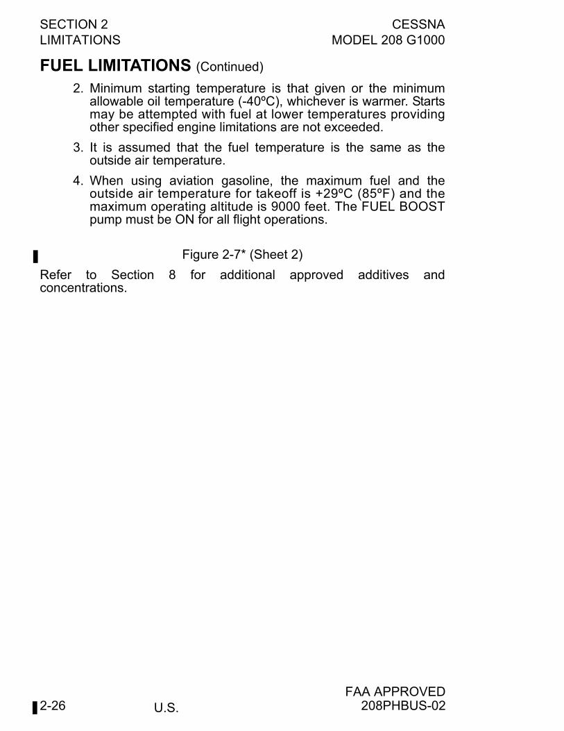
2. Minimum starting temperature is that given or the minimumallowable oil temperature (-40ºC), whichever is warmer. Startsmay be attempted with fuel at lower temperatures providingother specified engine limitations are not exceeded.
3. It is assumed that the fuel temperature is the same as theoutside air temperature.
4. When using aviation gasoline, the maximum fuel and theoutside air temperature for takeoff is +29ºC (85ºF) and themaximum operating altitude is 9000 feet. The FUEL BOOSTpump must be ON for all flight operations.
Figure 2-7* (Sheet 2)
Refer to Section 8 for additional approved additives andconcentrations.
208PHBUS-02
CESSNA SECTION 2MODEL 208 G1000 LIMITATIONS
U.S.FAA APPROVED
2-27
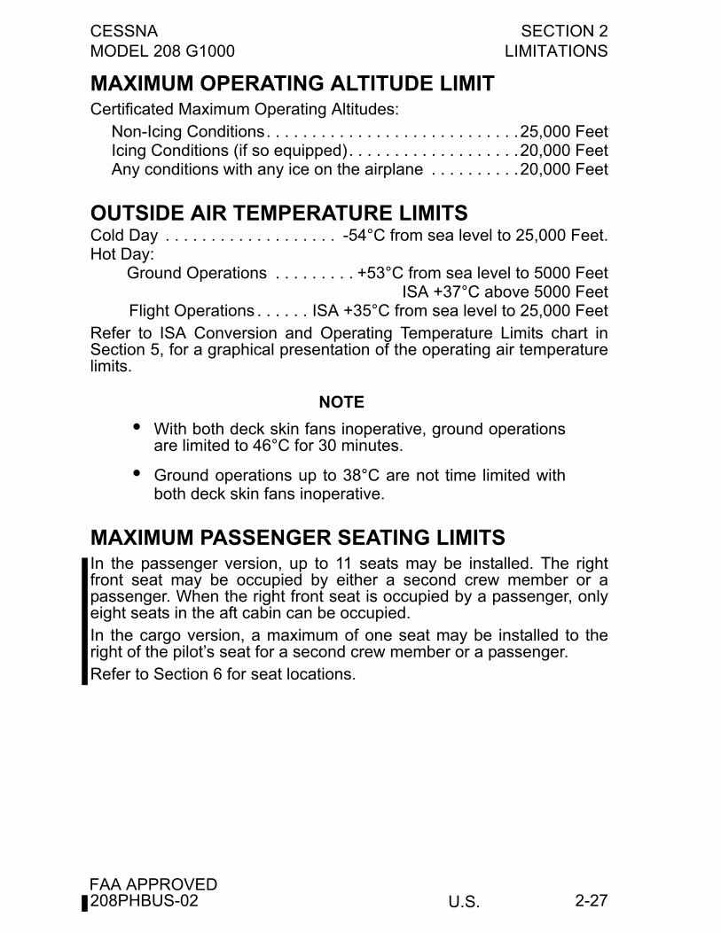
MAXIMUM OPERATING ALTITUDE LIMITCertificated Maximum Operating Altitudes:
Non-Icing Conditions. . . . . . . . . . . . . . . . . . . . . . . . . . . .25,000 FeetIcing Conditions (if so equipped). . . . . . . . . . . . . . . . . . .20,000 FeetAny conditions with any ice on the airplane . . . . . . . . . .20,000 Feet
OUTSIDE AIR TEMPERATURE LIMITSCold Day . . . . . . . . . . . . . . . . . . . -54°C from sea level to 25,000 Feet.Hot Day:
Ground Operations . . . . . . . . . +53°C from sea level to 5000 FeetISA +37°C above 5000 Feet
Flight Operations . . . . . . ISA +35°C from sea level to 25,000 FeetRefer to ISA Conversion and Operating Temperature Limits chart inSection 5, for a graphical presentation of the operating air temperaturelimits.
NOTE
• With both deck skin fans inoperative, ground operationsare limited to 46°C for 30 minutes.
• Ground operations up to 38°C are not time limited withboth deck skin fans inoperative.
MAXIMUM PASSENGER SEATING LIMITSIn the passenger version, up to 11 seats may be installed. The rightfront seat may be occupied by either a second crew member or apassenger. When the right front seat is occupied by a passenger, onlyeight seats in the aft cabin can be occupied.In the cargo version, a maximum of one seat may be installed to theright of the pilot’s seat for a second crew member or a passenger.Refer to Section 6 for seat locations.
208PHBUS-02

SECTION 2 CESSNALIMITATIONS MODEL 208 G1000
U.S.FAA APPROVED
2-28
OTHER LIMITATIONS
FLAP LIMITATIONSApproved Takeoff Range . . . . . . . . . . . . . . . . . . . . . . . . . . UP to 20°Approved Landing Range . . . . . . . . . . . . . . . . . . . . . . . .UP to FULLApproved Landing Range in Icing Conditions . . . . . . . . . . UP to 20°
STANDBY ELECTRIC SYSTEMWhen operating the standby electrical system, the maximum electricalload is 75 amps from sea level to 21,000 feet. To ensure adequatealternator cooling at higher altitudes, reduce maximum standbyelectrical system load 5 amps per 1000 feet above 21,000 feet.
TYPE II, TYPE III OR TYPE IV ANTI-ICE FLUIDTAKEOFF LIMITATIONS
FLAP LIMITATIONSTakeoff Flaps Setting . . . . . . . . . . . . . . . . . . . . . . . . . . . . . . . . . . .UP
AIRSPEED LIMITATIONSTakeoff Rotation Speed . . . . . . . . . . . . . . . . . . . . . . . . . . . . 89 KIAS
208PHBUS-02
CESSNA SECTION 2MODEL 208 G1000 LIMITATIONS
U.S.FAA APPROVED
2-29
FLIGHT IN KNOWN ICING VISUAL CUESAs Required by AD 96-09-15, Paragraph (a) (1)
WARNING
Severe icing may result from environmentalconditions outside of those for which the airplaneis certificated. Flight in freezing rain, freezingdrizzle, or mixed icing conditions (supercooledliquid water and ice crystals) may result in icebuild-up on protected surfaces exceeding thecapability of the ice protection system, or mayresult in ice forming aft of the protected surfaces.This ice may not be shed using the ice protectionsystems, and may seriously degrade theperformance and controllability of the airplane.
During flight, severe icing conditions that exceed those for which theairplane is certificated shall be determined by the following visual cues.If one or more of these visual cues exists, immediately request priorityhandling from Air Traffic Control to facilitate a route or an altitudechange to exit the icing conditions.
1. Unusually extensive ice is accreted on the airframe in areas notnormally observed to collect ice.
2. Accumulation of ice on the upper or lower surface of the wing aftof the protected area.
3. Heavy ice accumulations on the windshield, or when ice forms aftof the curved sections on the windshield.
4. Ice forms aft of the protected surfaces of the wing struts.Since the autopilot may mask tactile cues that indicate adversechanges in handling characteristics, use of the autopilot is prohibitedwhen any of the visual cues specified above exist, or when unusuallateral trim requirements or autopilot trim warnings are encounteredwhile the airplane is in icing conditions.
208PHBUS-02
SECTION 2 CESSNALIMITATIONS MODEL 208 G1000
U.S.FAA APPROVED
2-30
G1000 LIMITATIONSThe current Garmin G1000 Cockpit Reference Guide (CRG) PartNumber and System Software Version that must be available to thepilot during flight are displayed on the MFD AUX group, SYSTEMSTATUS page.GPS based IFR enroute, oceanic and terminal navigation is prohibitedunless the pilot verifies the currency of the database or verifies eachselected waypoint for accuracy by reference to current approved data.RNAV/GPS instrument approaches must be accomplished inaccordance with approved instrument approach procedures that areretrieved from the G1000 navigation database. The G1000 databasemust incorporate the current update cycle.Use of the NAVIGATION MAP page for pilotage navigation isprohibited. The Navigation Map is intended only to enhance situationalawareness. Navigation is to be conducted using only current charts,data and authorized navigation facilities.Use of the TERRAIN PROXIMITY information for primary terrainavoidance is prohibited. The Terrain Proximity map is intended only toenhance situational awareness. It is the pilot’s responsibility to provideterrain clearance at all times. In addition, Terrain Proximity informationis not available in locations north of 75° North latitude or south of 60°South latitude due to the absence of terrain data in these geographicalareas.Navigation using the G1000 is not authorized north of 72° North latitudeor south of 70° South latitude due to unsuitability of the magnetic fieldsnear the Earth's poles. In addition, operations are not authorized in thefollowing regions:
1. North of 65° North latitude between longitude 75° W and 120° W(Northern Canada).
2. North of 70° North latitude between longitude 70° W and 128° W(Northern Canada).
3. North of 70° North latitude between longitude 85° E and 114° E(Northern Russia).
4. South of 55° South latitude between longitude 120° E and 165° E(region south of Australia and New Zealand).
(Continued Next Page)
208PHBUS-02
CESSNA SECTION 2MODEL 208 G1000 LIMITATIONS
U.S.FAA APPROVED
2-31
G1000 LIMITATIONS (Continued)
The COM 1/2 (split COM) function of the Audio Panel is not approvedfor use. During COM 1/2 operation, transmission by one crew memberinhibits reception by the other crew member.The fuel quantity, fuel used and fuel remaining functions of the G1000are advisory information only and must be verified by the pilot.Dispatch with GIA1, 2, PFD, or MFD cooling advisory message isprohibited.
OPERATIONAL APPROVALSThe Garmin G1000 GPS receivers are approved under TSO C145aClass 3. The Garmin G1000 system has been demonstrated capableof, and has been shown to meet the accuracy requirements for, thefollowing operations provided it is receiving usable navigation data.These do not constitute operational approvals.
1. Enroute, terminal, non-precision instrument approach operationsusing GPS and WAAS (including "GPS", "or GPS", and "RNAV"approaches), and approach procedures with vertical guidance(including "LNAV/VNAV", "LNAV + V", and "LPV") within the U.S.National Airspace System in accordance with AC 20-138A.
2. As a required Long Range Navigation (LRN) system for use inthe following types of airspace when used in conjunction withGarmin WAAS Fault Detection/Exclusion Prediction Program,part number 006-A0154-01 or later approved version:a. Oceanic/Remote - RNP-10 (per FAA AC 20-138A, FAA
Notice 8110-60, FAA Order 8400-12A, and FAA Order 8700-1). Both GPS receivers are required to be operating andreceiving usable signals except for routes requiring only oneLong Range Navigation (LRN) sensor.
NOTE
Each display computes an independent navigation solutionbased on the on-side GPS sensor. However, either displaywill automatically revert to the cross-side sensor if theon-side sensor fails or if the cross-side sensor isdetermined to be more accurate. A “BOTH ON GPS1” or“BOTH ON GPS2” message does not necessarily meanthat one GPS has failed. Refer to the MFD AUX-GPSSTATUS page to determine the status of the unused GPS.
(Continued Next Page)
208PHBUS-02
SECTION 2 CESSNALIMITATIONS MODEL 208 G1000
U.S.FAA APPROVED
2-32
OPERATIONAL APPROVALS (Continued)b. North Atlantic (NAT) Minimum Navigational Performance
Specifications (MNPS) Airspace per AC 91-49 and AC120-33. Both GPS receivers are required to be operatingand receiving usable signals except for routes requiring onlyone Long Range Navigation sensor.
c. Enroute and Terminal including RNP5/BRNAV and PRNAV(RNP-1) - In accordance with JAA TGL-10, ACJ 20X4, AC90-96A, and AC 90-100A, provided the FMS is receivingusable navigation information from one or more GPSreceivers.
GARMIN GFC 700 AUTOMATED FLIGHT CONTROLSYSTEM (AFCS)
1. The GFC 700 AFCS preflight test must be successfullycompleted prior to use of the autopilot, flight director or manualelectric trim.
2. A pilot, with the seat belt fastened, must occupy the left pilot’sseat during all autopilot operations.
3. The autopilot and yaw damper must be off during all takeoff andlandings.
4. Autopilot maximum engagement speed . . . . . . . . . . . 175 KIASAutopilot minimum engagement speed . . . . . . . . . . . . . 80 KIASElectric Trim maximum operating speed . . . . . . . . . . . 175 KIAS
5. The autopilot must be disengaged below 200 feet AGL duringapproach operations and below 800 feet AGL during all otheroperations.
6. ILS approaches using the autopilot/flight director are limited toCategory I approaches only.
7. Raw data ILS approaches below 400 feet AGL are prohibited. 8. Use of the autopilot is prohibited when the audio panel is
inoperative (since the aural alert will not be provided whenautopilot is disengaged).
9. When conducting a missed approach, use of the autopilot isprohibited until a rate of climb is established that will meet allaltitude requirements of the missed approach procedure.
10.Autopilot operations with the yaw damper (YD) disengaged areprohibited.
208PHBUS-02
CESSNA SECTION 2MODEL 208 G1000 LIMITATIONS
U.S.FAA APPROVED
2-33
L3 COMMUNICATIONS WX 500 STORMSCOPE (ifinstalled)Use of the WEATHER MAP (WX-500 Stormscope) for hazardousweather (thunderstorm) penetration is prohibited. LTNG information onthe NAVIGATION MAP or WEATHER MAP is approved only as an aidto hazardous weather avoidance, not penetration.User’s guide should be available to the pilot in flight.
TRAFFIC ADVISORY SYSTEM (TAS) (if installed)Use of the TRAFFIC MAP to maneuver the airplane to avoid traffic isprohibited. TAS is intended for advisory use only. TAS is intended onlyto help the pilot to visually locate traffic. It is the responsibility of thepilot to see and maneuver to avoid traffic.TAS is unable to detect any intruding aircraft without an operatingtransponder. TAS can detect and track aircraft with either an ATCRBS(operating in Mode A or C) or Mode S transponders.ATC procedures and the “see and avoid concept” will continue to be theprimary means of aircraft separation. However, if communication is lostwith ATC, TAS adds a significant backup for collision avoidance.
TERRAIN AWARENESS AND WARNING SYSTEM (TAWS-B) (if installed)Use of the Terrain Awareness and Warning System (TAWS-B) tonavigate to avoid terrain or obstacles is prohibited. TAWS-B is onlyapproved as an aid to help the pilot to see-and-avoid terrain orobstacles.TAWS-B must be inhibited when landing at a location not included inthe airport database.Use of TAWS-B is prohibited when operating using the QFE altimetersetting (altimeter indicates 0 feet altitude when the airplane is on therunway).The pilot is authorized to deviate from the current ATC clearance onlyto the extent necessary to comply with TAWS-B warnings.
TAWS-B is not available in locations north of 75° North latitude or southof 60° South latitude due to the absence of terrain data in thesegeographical areas.
OPTIONAL EQUIPMENT USER’S GUIDEThe pilot is responsible for ensuring the appropriate user’s guide(s) forall optional equipment installed in the aircraft is accessible to the pilot inflight.
208PHBUS-02
SECTION 2 CESSNALIMITATIONS MODEL 208 G1000
U.S.FAA APPROVED
2-34
PLACARDS
WARNING
The following information must be displayed in theform of composite or individual placards. As aminimum, the exact wording of these placards isrequired as specified in this section. Placardwording can be from part numbered placardsobtained from Cessna Aircraft Company orequivalent placards installed by an approved repairstation in accordance with normal maintenancepractices/procedures.
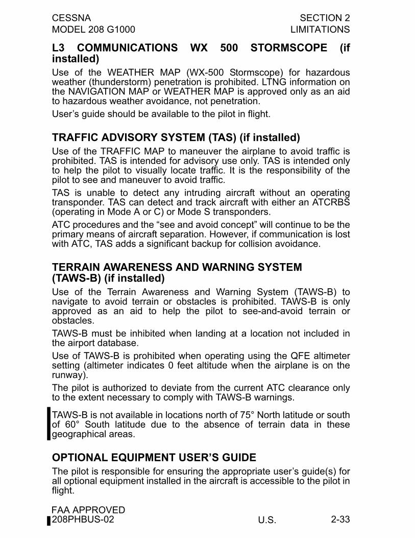
1. In full view of the pilot on the sunvisor or windshield trim strip onairplanes equipped for flight into known icing:
In full view of the pilot on the sunvisor or windshield trim strip onairplanes not equipped for flight into known icing:
(Continued Next Page)
208PHBUS-02
CESSNA SECTION 2MODEL 208 G1000 LIMITATIONS
U.S.FAA APPROVED
2-35
PLACARDS (Continued)
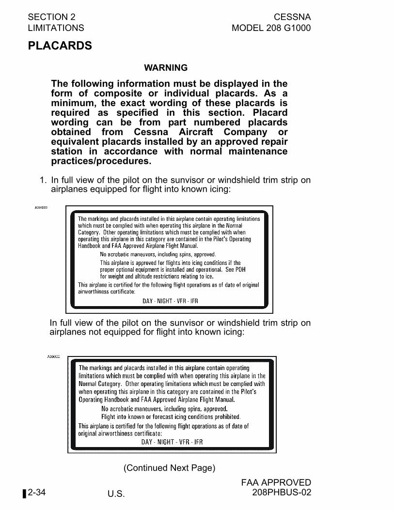
2. On pedestal:
3. On control lock:
4. On left sidewall below and forward of instrument panel and (whenright flight instrument panel is installed) on right sidewall belowand forward of instrument panel:
5. On sunvisor or windshield trim-strip:
6. Above Pilot PFD:
(Continued Next Page)
DO NOT TAKEOFF WITH ICE/FROST/SNOW ON THE AIRCRAFT
CAUTIONCONTROL LOCK
REMOVE BEFORE STARTING ENGINE
MAX WT. MANEUVER SPEED 148 KIASSEE POH FOR OTHER WEIGHTS
208PHBUS-02
SECTION 2 CESSNALIMITATIONS MODEL 208 G1000
U.S.FAA APPROVED
2-36
PLACARDS (Continued)
7. A calibration card must be provided to indicate the accuracy ofthe magnetic compass in 30° increments.
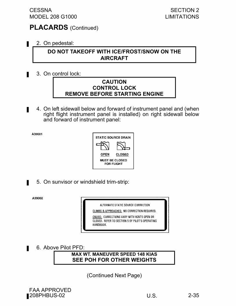
8. Near wing flap position indicator:
9. Below power lever:
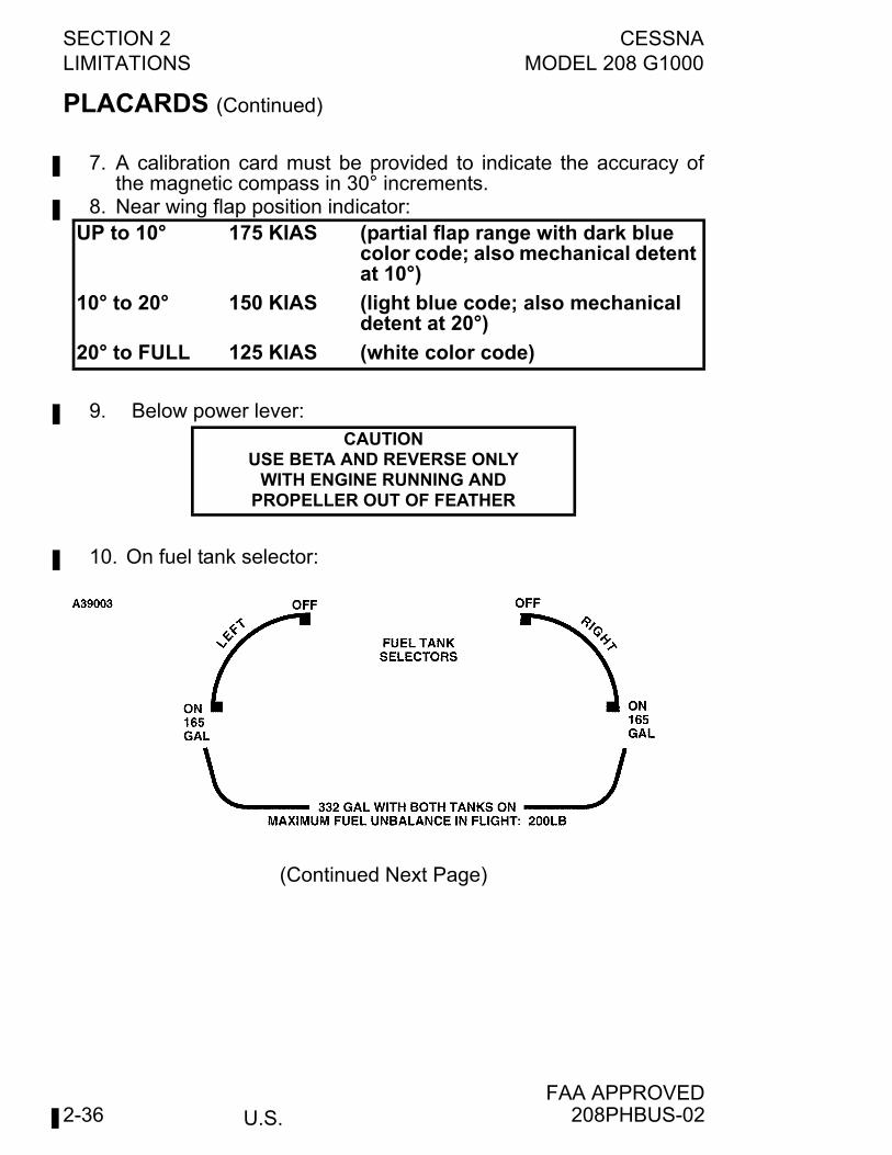
10. On fuel tank selector:
(Continued Next Page)
UP to 10° 175 KIAS (partial flap range with dark blue color code; also mechanical detent at 10°)
10° to 20° 150 KIAS (light blue code; also mechanical detent at 20°)
20° to FULL 125 KIAS (white color code)
CAUTIONUSE BETA AND REVERSE ONLY
WITH ENGINE RUNNING ANDPROPELLER OUT OF FEATHER
208PHBUS-02

CESSNA SECTION 2MODEL 208 G1000 LIMITATIONS
U.S.FAA APPROVED
2-37
PLACARDS (Continued)
11. Adjacent to each outboard fuel tank filler cap:
12. Adjacent to each inboard fuel tank filler cap (when installed)
(Continued Next Page)
208PHBUS-02
SECTION 2 CESSNALIMITATIONS MODEL 208 G1000
U.S.FAA APPROVED
2-38
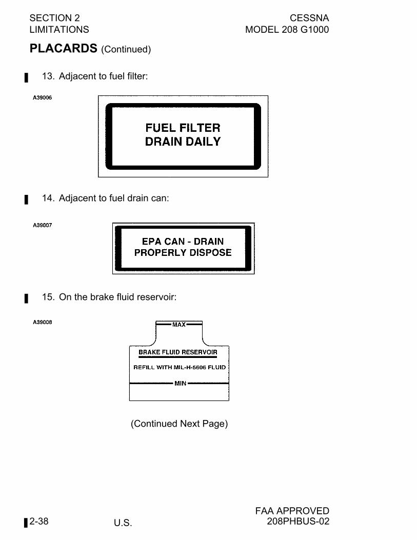
PLACARDS (Continued)
13. Adjacent to fuel filter:
14. Adjacent to fuel drain can:
15. On the brake fluid reservoir:
(Continued Next Page)
208PHBUS-02
CESSNA SECTION 2MODEL 208 G1000 LIMITATIONS
U.S.FAA APPROVED
2-39
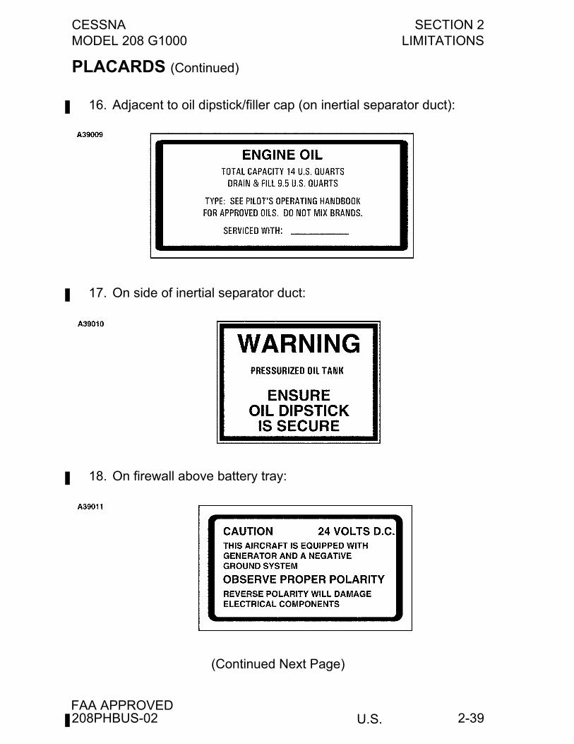
PLACARDS (Continued)
16. Adjacent to oil dipstick/filler cap (on inertial separator duct):
17. On side of inertial separator duct:
18. On firewall above battery tray:
(Continued Next Page)
208PHBUS-02
SECTION 2 CESSNALIMITATIONS MODEL 208 G1000
U.S.FAA APPROVED
2-40
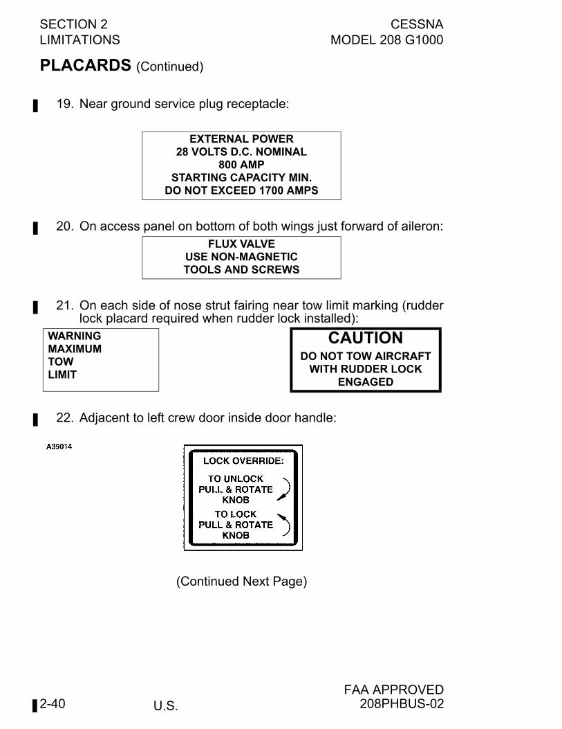
PLACARDS (Continued)
19. Near ground service plug receptacle:
20. On access panel on bottom of both wings just forward of aileron:
21. On each side of nose strut fairing near tow limit marking (rudderlock placard required when rudder lock installed):
22. Adjacent to left crew door inside door handle:
(Continued Next Page)
EXTERNAL POWER28 VOLTS D.C. NOMINAL
800 AMPSTARTING CAPACITY MIN.
DO NOT EXCEED 1700 AMPS
FLUX VALVEUSE NON-MAGNETICTOOLS AND SCREWS
WARNING MAXIMUM TOW LIMIT
CAUTIONDO NOT TOW AIRCRAFT
WITH RUDDER LOCK ENGAGED
208PHBUS-02
CESSNA SECTION 2MODEL 208 G1000 LIMITATIONS
U.S.FAA APPROVED
2-41
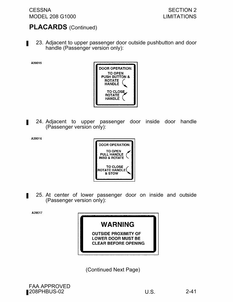
PLACARDS (Continued)
23. Adjacent to upper passenger door outside pushbutton and doorhandle (Passenger version only):
24. Adjacent to upper passenger door inside door handle(Passenger version only):
25. At center of lower passenger door on inside and outside(Passenger version only):
(Continued Next Page)
208PHBUS-02
SECTION 2 CESSNALIMITATIONS MODEL 208 G1000
U.S.FAA APPROVED
2-42
PLACARDS (Continued)
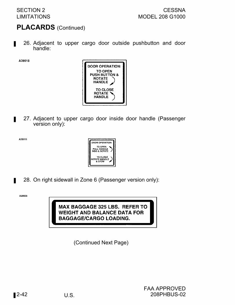
26. Adjacent to upper cargo door outside pushbutton and doorhandle:
27. Adjacent to upper cargo door inside door handle (Passengerversion only):
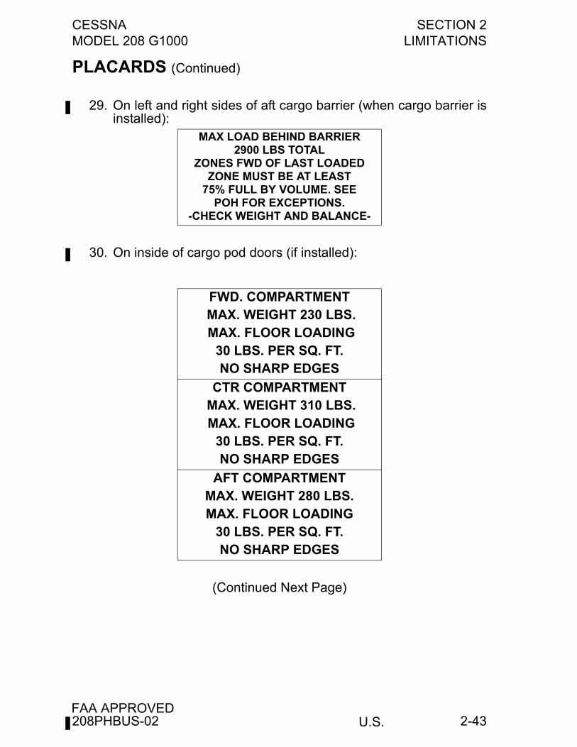
28. On right sidewall in Zone 6 (Passenger version only):
(Continued Next Page)
208PHBUS-02
CESSNA SECTION 2MODEL 208 G1000 LIMITATIONS
U.S.FAA APPROVED
2-43
PLACARDS (Continued)
29. On left and right sides of aft cargo barrier (when cargo barrier isinstalled):
30. On inside of cargo pod doors (if installed):
(Continued Next Page)
MAX LOAD BEHIND BARRIER2900 LBS TOTAL
ZONES FWD OF LAST LOADEDZONE MUST BE AT LEAST
75% FULL BY VOLUME. SEEPOH FOR EXCEPTIONS.
-CHECK WEIGHT AND BALANCE-
FWD. COMPARTMENT MAX. WEIGHT 230 LBS. MAX. FLOOR LOADING
30 LBS. PER SQ. FT. NO SHARP EDGES
CTR COMPARTMENT MAX. WEIGHT 310 LBS. MAX. FLOOR LOADING
30 LBS. PER SQ. FT.NO SHARP EDGES
AFT COMPARTMENTMAX. WEIGHT 280 LBS.MAX. FLOOR LOADING
30 LBS. PER SQ. FT.NO SHARP EDGES
208PHBUS-02
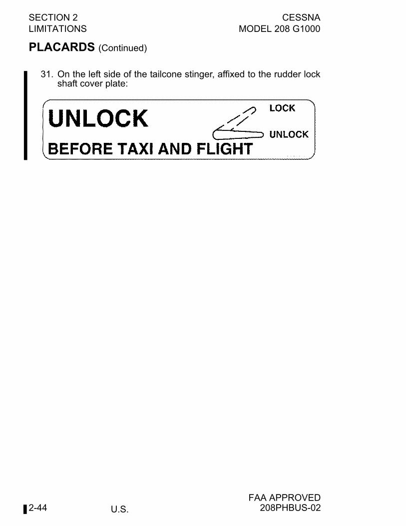
SECTION 2 CESSNALIMITATIONS MODEL 208 G1000
U.S.FAA APPROVED
2-44
PLACARDS (Continued)
31. On the left side of the tailcone stinger, affixed to the rudder lockshaft cover plate:
208PHBUS-02
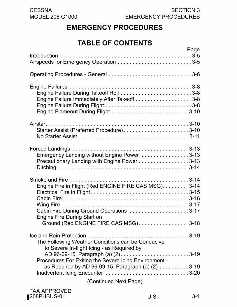
CESSNA SECTION 3MODEL 208 G1000 EMERGENCY PROCEDURES
U.S.FAA APPROVED
3-1
EMERGENCY PROCEDURES
TABLE OF CONTENTSPage
Introduction . . . . . . . . . . . . . . . . . . . . . . . . . . . . . . . . . . . . . . . . . . . .3-5Airspeeds for Emergency Operation . . . . . . . . . . . . . . . . . . . . . . . . .3-5
Operating Procedures - General . . . . . . . . . . . . . . . . . . . . . . . . . . . .3-6
Engine Failures . . . . . . . . . . . . . . . . . . . . . . . . . . . . . . . . . . . . . . . . .3-8Engine Failure During Takeoff Roll . . . . . . . . . . . . . . . . . . . . . . . .3-8Engine Failure Immediately After Takeoff . . . . . . . . . . . . . . . . . . 3-8Engine Failure During Flight . . . . . . . . . . . . . . . . . . . . . . . . . . . . .3-8Engine Flameout During Flight . . . . . . . . . . . . . . . . . . . . . . . . . 3-10
Airstart . . . . . . . . . . . . . . . . . . . . . . . . . . . . . . . . . . . . . . . . . . . . . . .3-10Starter Assist (Preferred Procedure) . . . . . . . . . . . . . . . . . . . . . .3-10No Starter Assist . . . . . . . . . . . . . . . . . . . . . . . . . . . . . . . . . . . . . 3-11
Forced Landings . . . . . . . . . . . . . . . . . . . . . . . . . . . . . . . . . . . . . . 3-13Emergency Landing without Engine Power . . . . . . . . . . . . . . . .3-13Precautionary Landing with Engine Power . . . . . . . . . . . . . . . . .3-13Ditching . . . . . . . . . . . . . . . . . . . . . . . . . . . . . . . . . . . . . . . . . . . 3-14
Smoke and Fire . . . . . . . . . . . . . . . . . . . . . . . . . . . . . . . . . . . . . . . .3-14Engine Fire in Flight (Red ENGINE FIRE CAS MSG). . . . . . . . 3-14Electrical Fire in Flight. . . . . . . . . . . . . . . . . . . . . . . . . . . . . . . . .3-15Cabin Fire . . . . . . . . . . . . . . . . . . . . . . . . . . . . . . . . . . . . . . . . . .3-16Wing Fire. . . . . . . . . . . . . . . . . . . . . . . . . . . . . . . . . . . . . . . . . . .3-17Cabin Fire During Ground Operations . . . . . . . . . . . . . . . . . . . .3-17Engine Fire During Start on
Ground (Red ENGINE FIRE CAS MSG) . . . . . . . . . . . . . . . . 3-18
Ice and Rain Protection . . . . . . . . . . . . . . . . . . . . . . . . . . . . . . . . . .3-19The Following Weather Conditions can be Conducive
to Severe In-flight Icing - as Required byAD 96-09-15, Paragraph (a) (2) . . . . . . . . . . . . . . . . . . . . . . .3-19
Procedures For Exiting the Severe Icing Environment -as Required by AD 96-09-15, Paragraph (a) (2) . . . . . . . . . .3-19
Inadvertent Icing Encounter . . . . . . . . . . . . . . . . . . . . . . . . . . . .3-20
(Continued Next Page)
208PHBUS-01
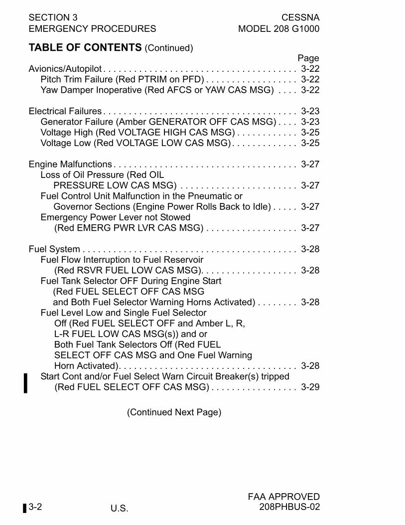
SECTION 3 CESSNAEMERGENCY PROCEDURES MODEL 208 G1000
U.S.FAA APPROVED
3-2
TABLE OF CONTENTS (Continued)Page
Avionics/Autopilot . . . . . . . . . . . . . . . . . . . . . . . . . . . . . . . . . . . . . . 3-22Pitch Trim Failure (Red PTRIM on PFD) . . . . . . . . . . . . . . . . . . 3-22Yaw Damper Inoperative (Red AFCS or YAW CAS MSG) . . . . 3-22
Electrical Failures . . . . . . . . . . . . . . . . . . . . . . . . . . . . . . . . . . . . . . 3-23Generator Failure (Amber GENERATOR OFF CAS MSG) . . . . 3-23Voltage High (Red VOLTAGE HIGH CAS MSG) . . . . . . . . . . . . 3-25Voltage Low (Red VOLTAGE LOW CAS MSG) . . . . . . . . . . . . . 3-25
Engine Malfunctions . . . . . . . . . . . . . . . . . . . . . . . . . . . . . . . . . . . . 3-27Loss of Oil Pressure (Red OIL PRESSURE LOW CAS MSG) . . . . . . . . . . . . . . . . . . . . . . . 3-27Fuel Control Unit Malfunction in the Pneumatic or Governor Sections (Engine Power Rolls Back to Idle) . . . . . 3-27Emergency Power Lever not Stowed
(Red EMERG PWR LVR CAS MSG) . . . . . . . . . . . . . . . . . . 3-27
Fuel System . . . . . . . . . . . . . . . . . . . . . . . . . . . . . . . . . . . . . . . . . . 3-28Fuel Flow Interruption to Fuel Reservoir
(Red RSVR FUEL LOW CAS MSG). . . . . . . . . . . . . . . . . . . 3-28Fuel Tank Selector OFF During Engine Start
(Red FUEL SELECT OFF CAS MSGand Both Fuel Selector Warning Horns Activated) . . . . . . . . 3-28
Fuel Level Low and Single Fuel SelectorOff (Red FUEL SELECT OFF and Amber L, R,L-R FUEL LOW CAS MSG(s)) and orBoth Fuel Tank Selectors Off (Red FUELSELECT OFF CAS MSG and One Fuel WarningHorn Activated). . . . . . . . . . . . . . . . . . . . . . . . . . . . . . . . . . . 3-28
Start Cont and/or Fuel Select Warn Circuit Breaker(s) tripped (Red FUEL SELECT OFF CAS MSG) . . . . . . . . . . . . . . . . . 3-29
(Continued Next Page)
208PHBUS-02
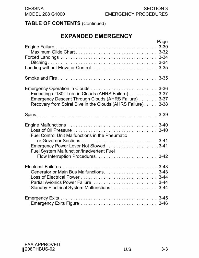
CESSNA SECTION 3MODEL 208 G1000 EMERGENCY PROCEDURES
U.S.FAA APPROVED
3-3
TABLE OF CONTENTS (Continued)
EXPANDED EMERGENCYPage
Engine Failure . . . . . . . . . . . . . . . . . . . . . . . . . . . . . . . . . . . . . . . . 3-30Maximum Glide Chart . . . . . . . . . . . . . . . . . . . . . . . . . . . . . . . . 3-32
Forced Landings . . . . . . . . . . . . . . . . . . . . . . . . . . . . . . . . . . . . . . 3-34Ditching . . . . . . . . . . . . . . . . . . . . . . . . . . . . . . . . . . . . . . . . . . . 3-34
Landing without Elevator Control . . . . . . . . . . . . . . . . . . . . . . . . . . 3-35
Smoke and Fire . . . . . . . . . . . . . . . . . . . . . . . . . . . . . . . . . . . . . . . 3-35
Emergency Operation in Clouds . . . . . . . . . . . . . . . . . . . . . . . . . . 3-36Executing a 180° Turn in Clouds (AHRS Failure) . . . . . . . . . . . 3-37Emergency Descent Through Clouds (AHRS Failure) . . . . . . . 3-37Recovery from Spiral Dive in the Clouds (AHRS Failure) . . . . . 3-38
Spins . . . . . . . . . . . . . . . . . . . . . . . . . . . . . . . . . . . . . . . . . . . . . . . 3-39
Engine Malfunctions . . . . . . . . . . . . . . . . . . . . . . . . . . . . . . . . . . . 3-40Loss of Oil Pressure . . . . . . . . . . . . . . . . . . . . . . . . . . . . . . . . . 3-40Fuel Control Unit Malfunctions in the Pneumatic
or Governor Sections . . . . . . . . . . . . . . . . . . . . . . . . . . . . . . 3-41Emergency Power Lever Not Stowed . . . . . . . . . . . . . . . . . . . . .3-41Fuel System Malfunction/Inadvertent Fuel
Flow Interruption Procedures . . . . . . . . . . . . . . . . . . . . . . . . 3-42
Electrical Failures . . . . . . . . . . . . . . . . . . . . . . . . . . . . . . . . . . . . . .3-43Generator or Main Bus Malfunctions. . . . . . . . . . . . . . . . . . . . . 3-43Loss of Electrical Power . . . . . . . . . . . . . . . . . . . . . . . . . . . . . . 3-44Partial Avionics Power Failure . . . . . . . . . . . . . . . . . . . . . . . . . 3-44Standby Electrical System Malfunctions . . . . . . . . . . . . . . . . . . 3-44
Emergency Exits . . . . . . . . . . . . . . . . . . . . . . . . . . . . . . . . . . . . . . 3-45Emergency Exits Figure . . . . . . . . . . . . . . . . . . . . . . . . . . . . . . 3-46
208PHBUS-02
SECTION 3 CESSNAEMERGENCY PROCEDURES MODEL 208 G1000
U.S.FAA APPROVED
3-4
This Page Intentionally Left Blank
208PHBUS-02
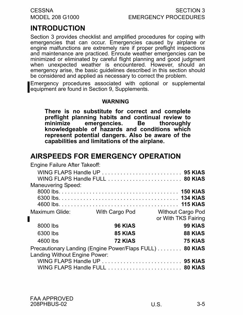
CESSNA SECTION 3MODEL 208 G1000 EMERGENCY PROCEDURES
U.S.FAA APPROVED
3-5
INTRODUCTIONSection 3 provides checklist and amplified procedures for coping withemergencies that can occur. Emergencies caused by airplane orengine malfunctions are extremely rare if proper preflight inspectionsand maintenance are practiced. Enroute weather emergencies can beminimized or eliminated by careful flight planning and good judgmentwhen unexpected weather is encountered. However, should anemergency arise, the basic guidelines described in this section shouldbe considered and applied as necessary to correct the problem. Emergency procedures associated with optional or supplementalequipment are found in Section 9, Supplements.
WARNING
There is no substitute for correct and completepreflight planning habits and continual review tominimize emergencies. Be thoroughlyknowledgeable of hazards and conditions whichrepresent potential dangers. Also be aware of thecapabilities and limitations of the airplane.
AIRSPEEDS FOR EMERGENCY OPERATIONEngine Failure After Takeoff:
WING FLAPS Handle UP . . . . . . . . . . . . . . . . . . . . . . . . . . 95 KIASWING FLAPS Handle FULL . . . . . . . . . . . . . . . . . . . . . . . . 80 KIAS
Maneuvering Speed:8000 lbs. . . . . . . . . . . . . . . . . . . . . . . . . . . . . . . . . . . . . . . 150 KIAS6300 lbs. . . . . . . . . . . . . . . . . . . . . . . . . . . . . . . . . . . . . . . 134 KIAS4600 lbs. . . . . . . . . . . . . . . . . . . . . . . . . . . . . . . . . . . . . . . 115 KIAS
Maximum Glide: With Cargo Pod Without Cargo Pod or With TKS Fairing
8000 lbs 96 KIAS 99 KIAS6300 lbs 85 KIAS 88 KIAS4600 lbs 72 KIAS 75 KIAS
Precautionary Landing (Engine Power/Flaps FULL) . . . . . . . . 80 KIASLanding Without Engine Power:
WING FLAPS Handle UP . . . . . . . . . . . . . . . . . . . . . . . . . . 95 KIASWING FLAPS Handle FULL . . . . . . . . . . . . . . . . . . . . . . . . 80 KIAS
208PHBUS-02
SECTION 3 CESSNAEMERGENCY PROCEDURES MODEL 208 G1000
U.S.FAA APPROVED
3-6
GENERAL
OPERATING PROCEDURES - GENERALThe operating procedures contained in this manual have beendeveloped and recommended by Cessna Aircraft Company and areapproved for use in the operation of this airplane.This section contains the Emergency and Abnormal Procedures foryour airplane. For your convenience, definitions of these terms arelisted in Section I. Operating procedures in this airplane flight manualare organized into Emergency, Abnormal, and Normal Procedures.Normal procedures are those recommended for routine day-to-daypreflight, flight, and postflight operation and include expanded systemsinformation and procedures. Some checks, as noted in the LimitationsSection of this airplane flight manual, are required to assure propersystem integrity.The Garmin G1000 Integrated Avionics System monitors most of theairplane systems for faults or failures and displays this information tothe crew as messages in the Crew Alerting System (CAS) portion of thePrimary Flight Display (PFD) in front of each pilot. Some Garmin G1000faults are also displayed as messages in the Primary Flight Display(PFD) or Multi Function Display (MFD). These messages are listedwithin the appropriate portion of the Emergency and Abnormalprocedures sections of the FAA Approved POH/AFM or appropriateGarmin Cockpit Reference Guide for the 208 series aircraft.Emergency procedures are generally associated with Red CASMSG(s) or Garmin G1000 messages. Some procedures, such asMaximum Glide/Emergency Landing, are not associated with anyparticular message, but can involve one or more messages. Allemergency procedures are organized by appropriate systems andinclude each Red CAS or Garmin message if applicable exactly as itappears on the PFD, or MFD. Emergency Procedures requireimmediate pilot recognition and corrective action by the crew. Red CASMSG(s) will flash and pressing the WARNING softkey will silence therepeating chime and change the CAS MSG to steady.
(Continued Next Page)
208PHBUS-02
CESSNA SECTION 3MODEL 208 G1000 EMERGENCY PROCEDURES
U.S.FAA APPROVED
3-7
OPERATING PROCEDURES - GENERAL (Continued)
Some emergency situations require immediate memorized correctiveaction. These numbered steps are printed in boxes within theemergency procedures and should be accomplished without the aid ofthe checklist.Abnormal Procedures are general procedures that can be associatedwith one or more Amber CAS, or Garmin G1000 messages. Someprocedures are not associated with any particular CAS or GarminG1000 message but can involve one or more messages. Theseprocedures are organized by related systems.An Abnormal Procedure is one requiring the use of special systemsand/or the alternate use of regular systems that will maintain anacceptable level of airworthiness. These procedures require immediatepilot awareness and subsequent crew action may be required. AmberCAS MSG(s) will initially flash. Pressing the CAUTION softkey willchange the CAS message to a steady state.
NOTE
• White CAS MSG(s) provide general information, indicatethe need for additional crew awareness and the possiblenecessity of future pilot action.
• In order to avoid confusion due to multiple messages, atcritical times, some CAS MSG(s) are inhibited when aLine Replaceable Unit (LRU), such as the GEA-71(Garmin Engine Airframe Computer), has failed.
• Generally, the following Emergency and AbnormalProcedures do not direct the pilot to check/reset circuitbreakers. This is considered basic airmanship and canbe accomplished at the pilot's discretion.
• Except where specific action is required, theseprocedures do not specify action when on the ground.Conditions resulting in a Red or Amber message shouldbe corrected prior to flight. Reasons for White CASMSG(s) should be determined prior to flight.
• If a Red or Amber CAS MSG occurs in flight,consideration should be given to landing at an airportwhere corrective maintenance can be performed.
208PHBUS-02
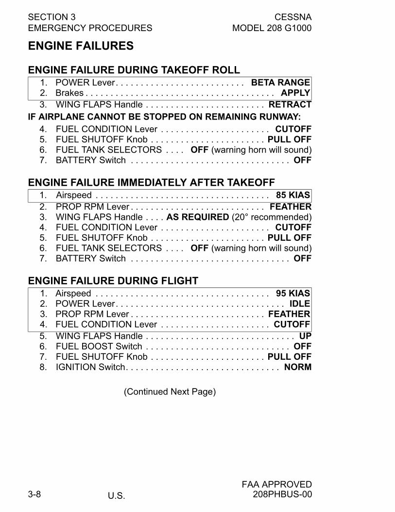
SECTION 3 CESSNAEMERGENCY PROCEDURES MODEL 208 G1000
U.S.FAA APPROVED
3-8
ENGINE FAILURES
ENGINE FAILURE DURING TAKEOFF ROLL
3. WING FLAPS Handle . . . . . . . . . . . . . . . . . . . . . . . . RETRACTIF AIRPLANE CANNOT BE STOPPED ON REMAINING RUNWAY:
4. FUEL CONDITION Lever . . . . . . . . . . . . . . . . . . . . . . CUTOFF5. FUEL SHUTOFF Knob . . . . . . . . . . . . . . . . . . . . . . . PULL OFF6. FUEL TANK SELECTORS . . . . OFF (warning horn will sound)7. BATTERY Switch . . . . . . . . . . . . . . . . . . . . . . . . . . . . . . . . OFF
ENGINE FAILURE IMMEDIATELY AFTER TAKEOFF
2. PROP RPM Lever . . . . . . . . . . . . . . . . . . . . . . . . . . . FEATHER3. WING FLAPS Handle . . . . AS REQUIRED (20° recommended)4. FUEL CONDITION Lever . . . . . . . . . . . . . . . . . . . . . . CUTOFF5. FUEL SHUTOFF Knob . . . . . . . . . . . . . . . . . . . . . . . PULL OFF6. FUEL TANK SELECTORS . . . . OFF (warning horn will sound)7. BATTERY Switch . . . . . . . . . . . . . . . . . . . . . . . . . . . . . . . . OFF
ENGINE FAILURE DURING FLIGHT
5. WING FLAPS Handle . . . . . . . . . . . . . . . . . . . . . . . . . . . . . . UP6. FUEL BOOST Switch . . . . . . . . . . . . . . . . . . . . . . . . . . . . . OFF7. FUEL SHUTOFF Knob . . . . . . . . . . . . . . . . . . . . . . . PULL OFF8. IGNITION Switch. . . . . . . . . . . . . . . . . . . . . . . . . . . . . . . NORM
(Continued Next Page)
1. POWER Lever. . . . . . . . . . . . . . . . . . . . . . . . . . BETA RANGE2. Brakes . . . . . . . . . . . . . . . . . . . . . . . . . . . . . . . . . . . . . . APPLY
1. Airspeed . . . . . . . . . . . . . . . . . . . . . . . . . . . . . . . . . . . 85 KIAS
1. Airspeed . . . . . . . . . . . . . . . . . . . . . . . . . . . . . . . . . . . 95 KIAS2. POWER Lever. . . . . . . . . . . . . . . . . . . . . . . . . . . . . . . . . . IDLE3. PROP RPM Lever . . . . . . . . . . . . . . . . . . . . . . . . . . . FEATHER4. FUEL CONDITION Lever . . . . . . . . . . . . . . . . . . . . . . CUTOFF
208PHBUS-00
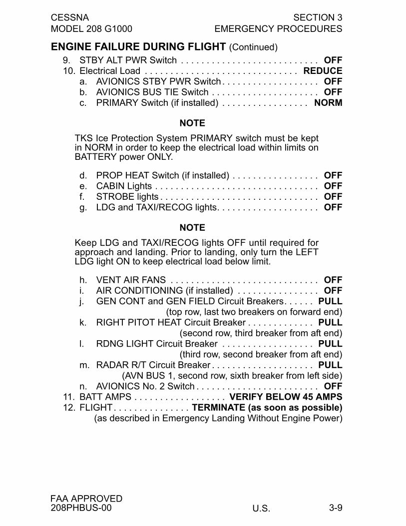
CESSNA SECTION 3MODEL 208 G1000 EMERGENCY PROCEDURES
U.S.FAA APPROVED
3-9
ENGINE FAILURE DURING FLIGHT (Continued)
9. STBY ALT PWR Switch . . . . . . . . . . . . . . . . . . . . . . . . . . . OFF10. Electrical Load . . . . . . . . . . . . . . . . . . . . . . . . . . . . . . REDUCE
a. AVIONICS STBY PWR Switch . . . . . . . . . . . . . . . . . . . OFFb. AVIONICS BUS TIE Switch . . . . . . . . . . . . . . . . . . . . . OFFc. PRIMARY Switch (if installed) . . . . . . . . . . . . . . . . . NORM
NOTE
TKS Ice Protection System PRIMARY switch must be keptin NORM in order to keep the electrical load within limits onBATTERY power ONLY.
d. PROP HEAT Switch (if installed) . . . . . . . . . . . . . . . . . OFFe. CABIN Lights . . . . . . . . . . . . . . . . . . . . . . . . . . . . . . . . OFFf. STROBE lights . . . . . . . . . . . . . . . . . . . . . . . . . . . . . . . OFFg. LDG and TAXI/RECOG lights. . . . . . . . . . . . . . . . . . . . OFF
NOTE
Keep LDG and TAXI/RECOG lights OFF until required forapproach and landing. Prior to landing, only turn the LEFTLDG light ON to keep electrical load below limit.
h. VENT AIR FANS . . . . . . . . . . . . . . . . . . . . . . . . . . . . . OFFi. AIR CONDITIONING (if installed) . . . . . . . . . . . . . . . . OFFj. GEN CONT and GEN FIELD Circuit Breakers. . . . . . PULL
(top row, last two breakers on forward end)k. RIGHT PITOT HEAT Circuit Breaker . . . . . . . . . . . . . PULL
(second row, third breaker from aft end)l. RDNG LIGHT Circuit Breaker . . . . . . . . . . . . . . . . . . PULL
(third row, second breaker from aft end)m. RADAR R/T Circuit Breaker . . . . . . . . . . . . . . . . . . . . PULL
(AVN BUS 1, second row, sixth breaker from left side)n. AVIONICS No. 2 Switch . . . . . . . . . . . . . . . . . . . . . . . . OFF
11. BATT AMPS . . . . . . . . . . . . . . . . . . VERIFY BELOW 45 AMPS12. FLIGHT. . . . . . . . . . . . . . . TERMINATE (as soon as possible)
(as described in Emergency Landing Without Engine Power)
208PHBUS-00
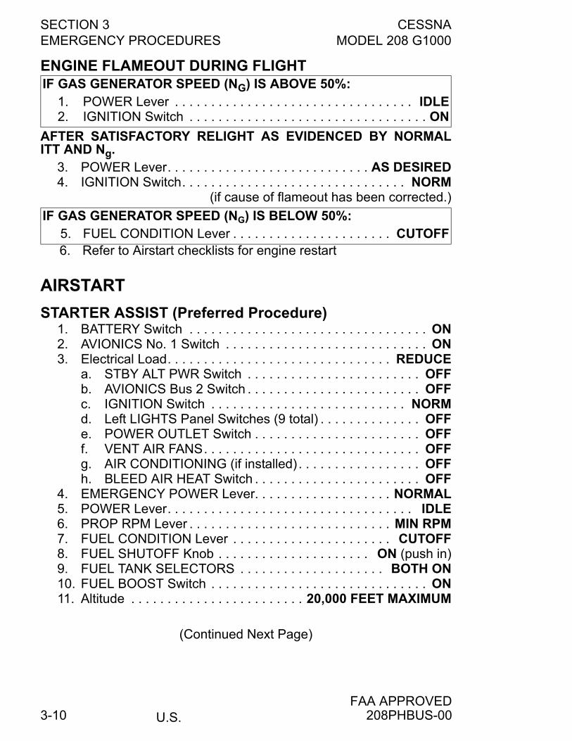
SECTION 3 CESSNAEMERGENCY PROCEDURES MODEL 208 G1000
U.S.FAA APPROVED
3-10
ENGINE FLAMEOUT DURING FLIGHT
AFTER SATISFACTORY RELIGHT AS EVIDENCED BY NORMALITT AND Ng.
3. POWER Lever. . . . . . . . . . . . . . . . . . . . . . . . . . . . AS DESIRED4. IGNITION Switch. . . . . . . . . . . . . . . . . . . . . . . . . . . . . . . NORM
(if cause of flameout has been corrected.)
6. Refer to Airstart checklists for engine restart
AIRSTART
STARTER ASSIST (Preferred Procedure)1. BATTERY Switch . . . . . . . . . . . . . . . . . . . . . . . . . . . . . . . . . ON2. AVIONICS No. 1 Switch . . . . . . . . . . . . . . . . . . . . . . . . . . . . ON3. Electrical Load. . . . . . . . . . . . . . . . . . . . . . . . . . . . . . . REDUCE
a. STBY ALT PWR Switch . . . . . . . . . . . . . . . . . . . . . . . . OFFb. AVIONICS Bus 2 Switch . . . . . . . . . . . . . . . . . . . . . . . . OFFc. IGNITION Switch . . . . . . . . . . . . . . . . . . . . . . . . . . . NORMd. Left LIGHTS Panel Switches (9 total) . . . . . . . . . . . . . . OFFe. POWER OUTLET Switch . . . . . . . . . . . . . . . . . . . . . . . OFFf. VENT AIR FANS. . . . . . . . . . . . . . . . . . . . . . . . . . . . . . OFFg. AIR CONDITIONING (if installed) . . . . . . . . . . . . . . . . . OFFh. BLEED AIR HEAT Switch . . . . . . . . . . . . . . . . . . . . . . . OFF
4. EMERGENCY POWER Lever. . . . . . . . . . . . . . . . . . . NORMAL5. POWER Lever. . . . . . . . . . . . . . . . . . . . . . . . . . . . . . . . . . IDLE6. PROP RPM Lever . . . . . . . . . . . . . . . . . . . . . . . . . . . . MIN RPM7. FUEL CONDITION Lever . . . . . . . . . . . . . . . . . . . . . . CUTOFF8. FUEL SHUTOFF Knob . . . . . . . . . . . . . . . . . . . . . ON (push in)9. FUEL TANK SELECTORS . . . . . . . . . . . . . . . . . . . . BOTH ON10. FUEL BOOST Switch . . . . . . . . . . . . . . . . . . . . . . . . . . . . . . ON11. Altitude . . . . . . . . . . . . . . . . . . . . . . . . 20,000 FEET MAXIMUM
(Continued Next Page)
IF GAS GENERATOR SPEED (NG) IS ABOVE 50%:1. POWER Lever . . . . . . . . . . . . . . . . . . . . . . . . . . . . . . . . . IDLE2. IGNITION Switch . . . . . . . . . . . . . . . . . . . . . . . . . . . . . . . . . ON
IF GAS GENERATOR SPEED (NG) IS BELOW 50%:5. FUEL CONDITION Lever . . . . . . . . . . . . . . . . . . . . . . CUTOFF
208PHBUS-00

CESSNA SECTION 3MODEL 208 G1000 EMERGENCY PROCEDURES
U.S.FAA APPROVED
3-11
STARTER ASSIST (Preferred Procedure) (Continued)
12. STARTER Switch . . . . . . . . . . . . . . . . . START and OBSERVEa. IGNITION ON CAS MSG . . . . . . . . . . . . . . . . . CHECK ONb. Engine Oil Pressure Indication. . . . . . . . . . . . . . . . CHECKc. Ng . . . . . . . . . . . . . . . . . . . . . . . . . . . . . . . . . 12% MINIMUM
13. FUEL CONDITION Lever . . . . . . . . LOW IDLE and OBSERVEa. FFLOW PPH . . . . . . . . . . . . . . . . . . . . . . . . . . 90-140 pphb. ITT . . . . . . . . . . . . . . . . . . . MONITOR (1090°C maximum)c. Ng . . . . . . . . . . . . . . . . . . . . . . . . . . . . . . . . . 52% MINIMUM
14. STARTER Switch . . . . . . . . . . . . . . . . . . . . . . . . . . . . . . . . OFF
WARNING
If conditions exist such as heavy precipitation ornearly empty fuel tanks, turn the IGNITION SwitchON.
15. FUEL BOOST Switch . . . . . . . . . . . . . . . . . . . . . . . . . . . NORM(unless it cycles on and off; then leave ON)
16. FUEL CONDITION Lever . . . . . . . . . . . . . . . . . . . . . HIGH IDLE17. PROP RPM Lever. . . . . . . . . . . . . . . . . . . . . . . . . . . . . . . . SET18. POWER Lever . . . . . . . . . . . . . . . . . . . . . . . . . . . . . . . . . . SET19. STBY ALT PWR Switch . . . . . . . . . . . . . . . . . . . . . . . . . . . . ON20. AVIONICS No. 2 Switch . . . . . . . . . . . . . . . . . . . . . . . . . . . . ON21. Electrical equipment . . . . . . . . . . . . . . . . . . . . . AS REQUIRED
NO STARTER ASSIST1. BATTERY Switch . . . . . . . . . . . . . . . . . . . . . . . . . . . . . . . . . ON2. GENERATOR Switch . . . . . . . . . . . . . . . . . . . . . . . . . . . . . TRIP
a. STBY ALT PWR Switch . . . . . . . . . . . . . . . . . . . . . . . . OFFb. AVIONICS Bus 2 Switch. . . . . . . . . . . . . . . . . . . . . . . . OFFc. Left LIGHTS Panel Switches (9 total). . . . . . . . . . . . . . OFFd. POWER OUTLET Switch. . . . . . . . . . . . . . . . . . . . . . . OFFe. VENT AIR FANS . . . . . . . . . . . . . . . . . . . . . . . . . . . . . OFFf. AIR CONDITIONING (if installed) . . . . . . . . . . . . . . . . OFFg. BLEED AIR HEAT Switch. . . . . . . . . . . . . . . . . . . . . . . OFF
3. EMERGENCY POWER Lever . . . . . . . . . . . . . . . . . . NORMAL4. POWER Lever . . . . . . . . . . . . . . . . . . . . . . . . . . . . . . . . . . IDLE5. PROP RPM Lever. . . . . . . . . . . . . . . . . . . . . . . . . . . . MIN RPM
(Continued Next Page)
208PHBUS-00
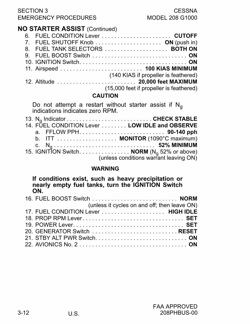
SECTION 3 CESSNAEMERGENCY PROCEDURES MODEL 208 G1000
U.S.FAA APPROVED
3-12
NO STARTER ASSIST (Continued)6. FUEL CONDITION Lever . . . . . . . . . . . . . . . . . . . . . . CUTOFF7. FUEL SHUTOFF Knob . . . . . . . . . . . . . . . . . . . . . ON (push in)8. FUEL TANK SELECTORS . . . . . . . . . . . . . . . . . . . . BOTH ON9. FUEL BOOST Switch . . . . . . . . . . . . . . . . . . . . . . . . . . . . . . ON10. IGNITION Switch. . . . . . . . . . . . . . . . . . . . . . . . . . . . . . . . . . ON11. Airspeed . . . . . . . . . . . . . . . . . . . . . . . . . . 100 KIAS MINIMUM
(140 KIAS if propeller is feathered)12. Altitude . . . . . . . . . . . . . . . . . . . . . . . . . 20,000 feet MAXIMUM
(15,000 feet if propeller is feathered)CAUTION
Do not attempt a restart without starter assist if Ngindications indicates zero RPM.
13. Ng Indicator . . . . . . . . . . . . . . . . . . . . . . . . . . . CHECK STABLE14. FUEL CONDITION Lever . . . . . . . . LOW IDLE and OBSERVE
a. FFLOW PPH. . . . . . . . . . . . . . . . . . . . . . . . . . . 90-140 pphb. ITT . . . . . . . . . . . . . . . . . . . MONITOR (1090°C maximum)c. Ng . . . . . . . . . . . . . . . . . . . . . . . . . . . . . . . . 52% MINIMUM
15. IGNITION Switch. . . . . . . . . . . . . . . . NORM (Ng 52% or above)(unless conditions warrant leaving ON)
WARNING
If conditions exist, such as heavy precipitation ornearly empty fuel tanks, turn the IGNITION SwitchON.
16. FUEL BOOST Switch . . . . . . . . . . . . . . . . . . . . . . . . . . . NORM(unless it cycles on and off; then leave ON)
17. FUEL CONDITION Lever . . . . . . . . . . . . . . . . . . . . HIGH IDLE18. PROP RPM Lever . . . . . . . . . . . . . . . . . . . . . . . . . . . . . . . . SET19. POWER Lever. . . . . . . . . . . . . . . . . . . . . . . . . . . . . . . . . . . SET20. GENERATOR Switch . . . . . . . . . . . . . . . . . . . . . . . . . . . RESET21. STBY ALT PWR Switch. . . . . . . . . . . . . . . . . . . . . . . . . . . . . ON22. AVIONICS No. 2 . . . . . . . . . . . . . . . . . . . . . . . . . . . . . . . . . . ON
208PHBUS-00
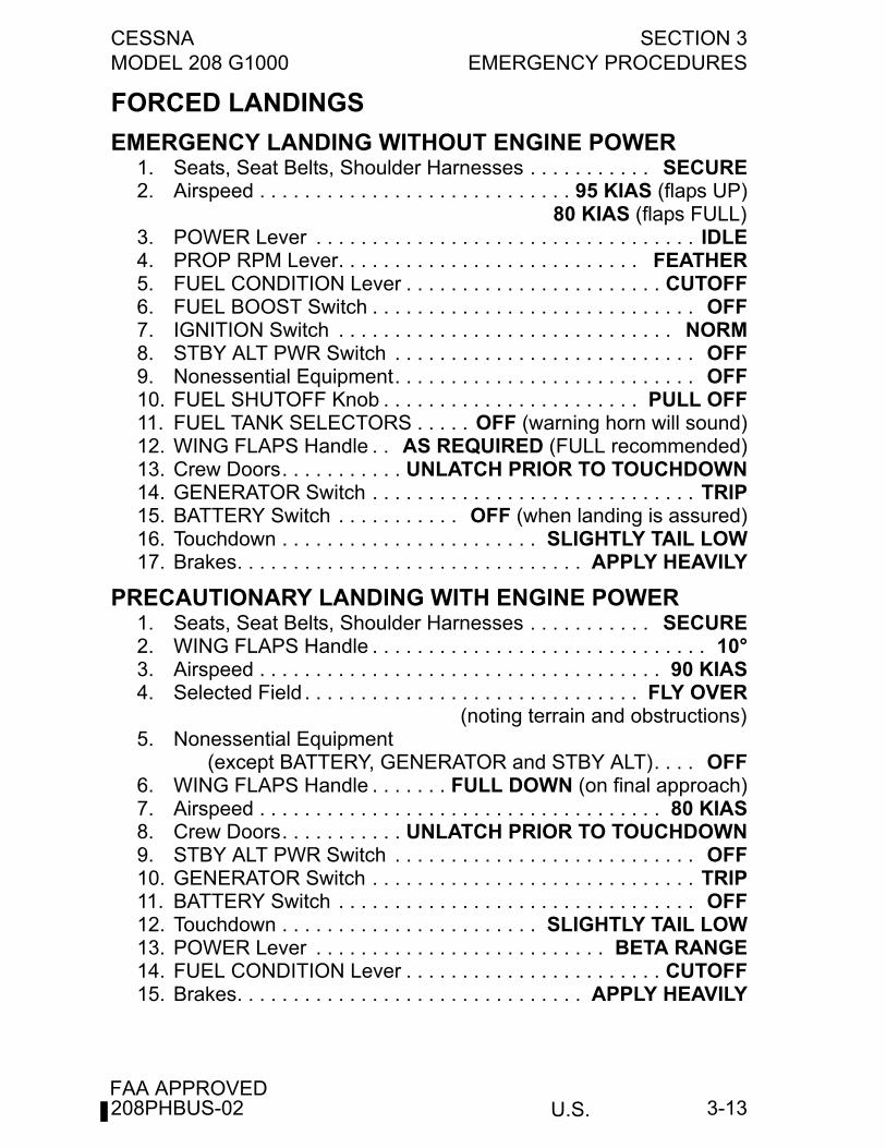
CESSNA SECTION 3MODEL 208 G1000 EMERGENCY PROCEDURES
U.S.FAA APPROVED
3-13
FORCED LANDINGS
EMERGENCY LANDING WITHOUT ENGINE POWER1. Seats, Seat Belts, Shoulder Harnesses . . . . . . . . . . . SECURE2. Airspeed . . . . . . . . . . . . . . . . . . . . . . . . . . . . 95 KIAS (flaps UP)
80 KIAS (flaps FULL)3. POWER Lever . . . . . . . . . . . . . . . . . . . . . . . . . . . . . . . . . . IDLE4. PROP RPM Lever. . . . . . . . . . . . . . . . . . . . . . . . . . . FEATHER5. FUEL CONDITION Lever . . . . . . . . . . . . . . . . . . . . . . . CUTOFF6. FUEL BOOST Switch . . . . . . . . . . . . . . . . . . . . . . . . . . . . . OFF7. IGNITION Switch . . . . . . . . . . . . . . . . . . . . . . . . . . . . . . NORM8. STBY ALT PWR Switch . . . . . . . . . . . . . . . . . . . . . . . . . . . OFF9. Nonessential Equipment. . . . . . . . . . . . . . . . . . . . . . . . . . . OFF10. FUEL SHUTOFF Knob . . . . . . . . . . . . . . . . . . . . . . . PULL OFF11. FUEL TANK SELECTORS . . . . . OFF (warning horn will sound)12. WING FLAPS Handle . . AS REQUIRED (FULL recommended)13. Crew Doors. . . . . . . . . . . UNLATCH PRIOR TO TOUCHDOWN14. GENERATOR Switch . . . . . . . . . . . . . . . . . . . . . . . . . . . . . TRIP15. BATTERY Switch . . . . . . . . . . . OFF (when landing is assured)16. Touchdown . . . . . . . . . . . . . . . . . . . . . . . SLIGHTLY TAIL LOW17. Brakes. . . . . . . . . . . . . . . . . . . . . . . . . . . . . . . APPLY HEAVILY
PRECAUTIONARY LANDING WITH ENGINE POWER1. Seats, Seat Belts, Shoulder Harnesses . . . . . . . . . . . SECURE2. WING FLAPS Handle . . . . . . . . . . . . . . . . . . . . . . . . . . . . . . 10°3. Airspeed . . . . . . . . . . . . . . . . . . . . . . . . . . . . . . . . . . . . 90 KIAS4. Selected Field . . . . . . . . . . . . . . . . . . . . . . . . . . . . . . FLY OVER
(noting terrain and obstructions)5. Nonessential Equipment
(except BATTERY, GENERATOR and STBY ALT). . . . OFF6. WING FLAPS Handle . . . . . . . FULL DOWN (on final approach)7. Airspeed . . . . . . . . . . . . . . . . . . . . . . . . . . . . . . . . . . . . 80 KIAS8. Crew Doors. . . . . . . . . . . UNLATCH PRIOR TO TOUCHDOWN9. STBY ALT PWR Switch . . . . . . . . . . . . . . . . . . . . . . . . . . . OFF10. GENERATOR Switch . . . . . . . . . . . . . . . . . . . . . . . . . . . . . TRIP11. BATTERY Switch . . . . . . . . . . . . . . . . . . . . . . . . . . . . . . . . OFF12. Touchdown . . . . . . . . . . . . . . . . . . . . . . . SLIGHTLY TAIL LOW13. POWER Lever . . . . . . . . . . . . . . . . . . . . . . . . . . BETA RANGE14. FUEL CONDITION Lever . . . . . . . . . . . . . . . . . . . . . . . CUTOFF15. Brakes. . . . . . . . . . . . . . . . . . . . . . . . . . . . . . . APPLY HEAVILY
208PHBUS-02
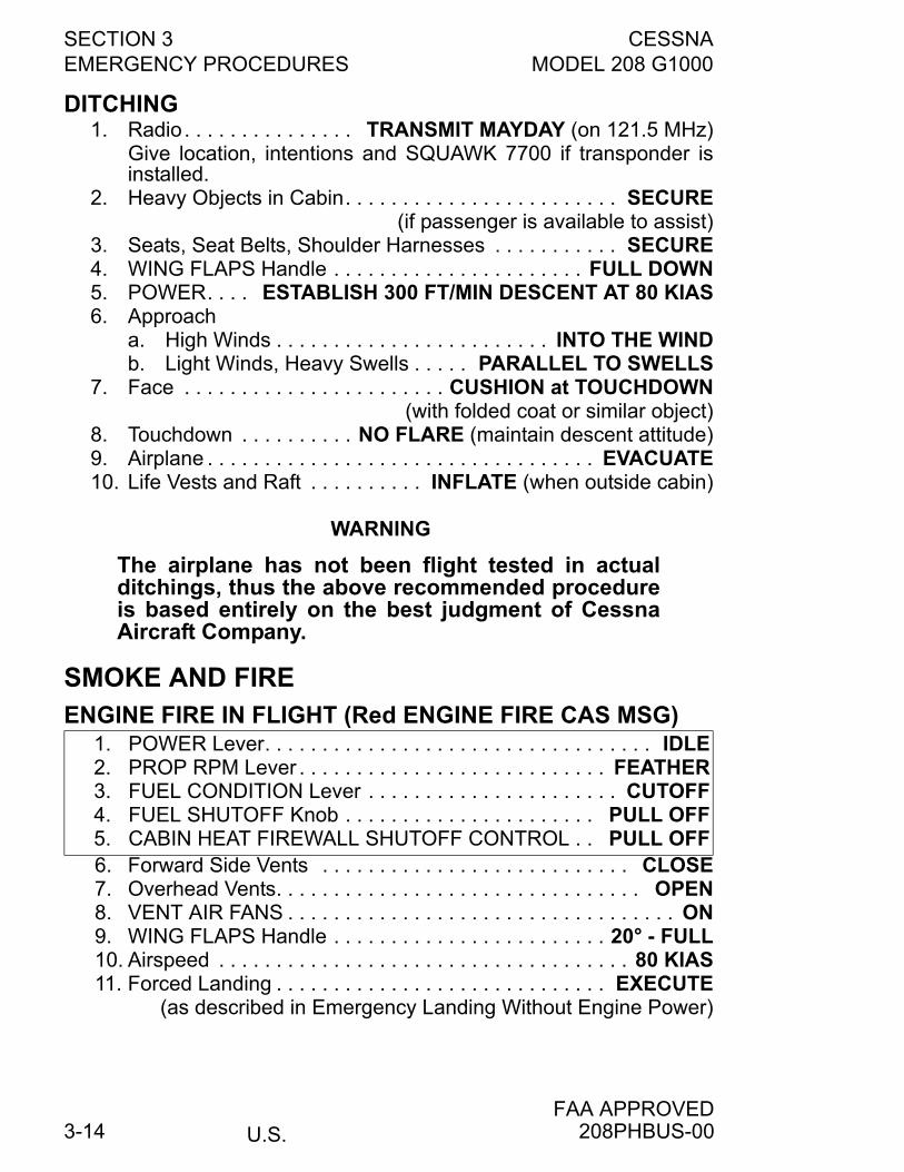
SECTION 3 CESSNAEMERGENCY PROCEDURES MODEL 208 G1000
U.S.FAA APPROVED
3-14
DITCHING1. Radio. . . . . . . . . . . . . . . TRANSMIT MAYDAY (on 121.5 MHz)
Give location, intentions and SQUAWK 7700 if transponder isinstalled.
2. Heavy Objects in Cabin. . . . . . . . . . . . . . . . . . . . . . . . SECURE(if passenger is available to assist)
3. Seats, Seat Belts, Shoulder Harnesses . . . . . . . . . . . SECURE4. WING FLAPS Handle . . . . . . . . . . . . . . . . . . . . . . FULL DOWN5. POWER. . . . ESTABLISH 300 FT/MIN DESCENT AT 80 KIAS6. Approach
a. High Winds . . . . . . . . . . . . . . . . . . . . . . . . INTO THE WINDb. Light Winds, Heavy Swells . . . . . PARALLEL TO SWELLS
7. Face . . . . . . . . . . . . . . . . . . . . . . . CUSHION at TOUCHDOWN(with folded coat or similar object)
8. Touchdown . . . . . . . . . . NO FLARE (maintain descent attitude)9. Airplane . . . . . . . . . . . . . . . . . . . . . . . . . . . . . . . . . . EVACUATE10. Life Vests and Raft . . . . . . . . . . INFLATE (when outside cabin)
WARNING
The airplane has not been flight tested in actualditchings, thus the above recommended procedureis based entirely on the best judgment of CessnaAircraft Company.
SMOKE AND FIREENGINE FIRE IN FLIGHT (Red ENGINE FIRE CAS MSG)
6. Forward Side Vents . . . . . . . . . . . . . . . . . . . . . . . . . . . CLOSE7. Overhead Vents. . . . . . . . . . . . . . . . . . . . . . . . . . . . . . . . OPEN8. VENT AIR FANS . . . . . . . . . . . . . . . . . . . . . . . . . . . . . . . . . . ON9. WING FLAPS Handle . . . . . . . . . . . . . . . . . . . . . . . . 20° - FULL10. Airspeed . . . . . . . . . . . . . . . . . . . . . . . . . . . . . . . . . . . . 80 KIAS11. Forced Landing . . . . . . . . . . . . . . . . . . . . . . . . . . . . . EXECUTE
(as described in Emergency Landing Without Engine Power)
1. POWER Lever. . . . . . . . . . . . . . . . . . . . . . . . . . . . . . . . . . IDLE2. PROP RPM Lever . . . . . . . . . . . . . . . . . . . . . . . . . . . FEATHER3. FUEL CONDITION Lever . . . . . . . . . . . . . . . . . . . . . . CUTOFF4. FUEL SHUTOFF Knob . . . . . . . . . . . . . . . . . . . . . . PULL OFF5. CABIN HEAT FIREWALL SHUTOFF CONTROL . . PULL OFF
208PHBUS-00
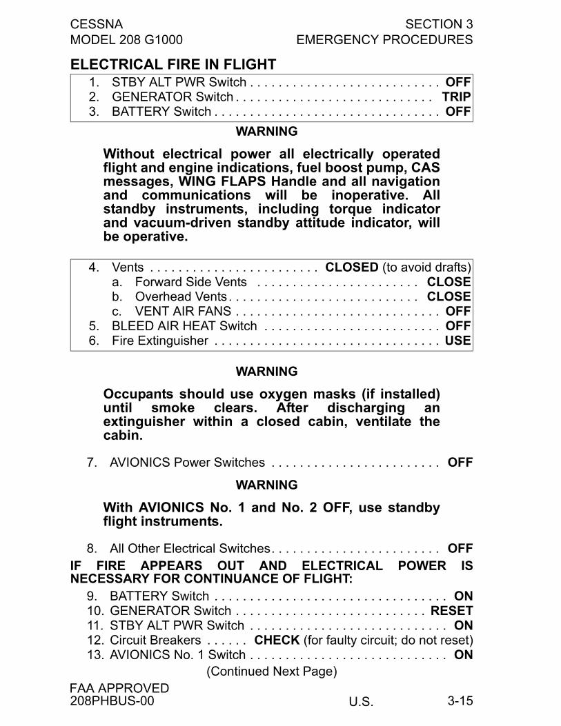
CESSNA SECTION 3MODEL 208 G1000 EMERGENCY PROCEDURES
U.S.FAA APPROVED
3-15
ELECTRICAL FIRE IN FLIGHT
WARNING
Without electrical power all electrically operatedflight and engine indications, fuel boost pump, CASmessages, WING FLAPS Handle and all navigationand communications will be inoperative. Allstandby instruments, including torque indicatorand vacuum-driven standby attitude indicator, willbe operative.
WARNING
Occupants should use oxygen masks (if installed)until smoke clears. After discharging anextinguisher within a closed cabin, ventilate thecabin.
7. AVIONICS Power Switches . . . . . . . . . . . . . . . . . . . . . . . . OFF
WARNING
With AVIONICS No. 1 and No. 2 OFF, use standbyflight instruments.
8. All Other Electrical Switches. . . . . . . . . . . . . . . . . . . . . . . . OFFIF FIRE APPEARS OUT AND ELECTRICAL POWER ISNECESSARY FOR CONTINUANCE OF FLIGHT:
9. BATTERY Switch . . . . . . . . . . . . . . . . . . . . . . . . . . . . . . . . . ON10. GENERATOR Switch . . . . . . . . . . . . . . . . . . . . . . . . . . . RESET11. STBY ALT PWR Switch . . . . . . . . . . . . . . . . . . . . . . . . . . . . ON12. Circuit Breakers . . . . . . CHECK (for faulty circuit; do not reset)13. AVIONICS No. 1 Switch . . . . . . . . . . . . . . . . . . . . . . . . . . . . ON
(Continued Next Page)
1. STBY ALT PWR Switch . . . . . . . . . . . . . . . . . . . . . . . . . . . OFF2. GENERATOR Switch . . . . . . . . . . . . . . . . . . . . . . . . . . . . TRIP3. BATTERY Switch . . . . . . . . . . . . . . . . . . . . . . . . . . . . . . . . OFF
4. Vents . . . . . . . . . . . . . . . . . . . . . . . . CLOSED (to avoid drafts)a. Forward Side Vents . . . . . . . . . . . . . . . . . . . . . . . CLOSEb. Overhead Vents. . . . . . . . . . . . . . . . . . . . . . . . . . . CLOSEc. VENT AIR FANS . . . . . . . . . . . . . . . . . . . . . . . . . . . . . OFF
5. BLEED AIR HEAT Switch . . . . . . . . . . . . . . . . . . . . . . . . . OFF6. Fire Extinguisher . . . . . . . . . . . . . . . . . . . . . . . . . . . . . . . . USE
208PHBUS-00
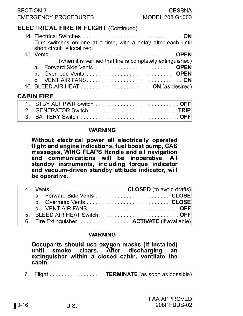
SECTION 3 CESSNAEMERGENCY PROCEDURES MODEL 208 G1000
U.S.FAA APPROVED
3-16
ELECTRICAL FIRE IN FLIGHT (Continued)
14. Electrical Switches . . . . . . . . . . . . . . . . . . . . . . . . . . . . . . . . ONTurn switches on one at a time, with a delay after each untilshort circuit is localized.
15. Vents . . . . . . . . . . . . . . . . . . . . . . . . . . . . . . . . . . . . . . . . OPEN(when it is verified that fire is completely extinguished)
a. Forward Side Vents . . . . . . . . . . . . . . . . . . . . . . . . . OPENb. Overhead Vents . . . . . . . . . . . . . . . . . . . . . . . . . . . . OPENc. VENT AIR FANS. . . . . . . . . . . . . . . . . . . . . . . . . . . . . . . ON
16. BLEED AIR HEAT . . . . . . . . . . . . . . . . . . . . . . . ON (as desired)
CABIN FIRE
WARNING
Without electrical power all electrically operatedflight and engine indications, fuel boost pump, CASmessages, WING FLAPS Handle and all navigationand communications will be inoperative. Allstandby instruments, including torque indicatorand vacuum-driven standby attitude indicator, willbe operative.
WARNING
Occupants should use oxygen masks (if installed)until smoke clears. After discharging anextinguisher within a closed cabin, ventilate thecabin.
7. Flight . . . . . . . . . . . . . . . . . . TERMINATE (as soon as possible)
1. STBY ALT PWR Switch . . . . . . . . . . . . . . . . . . . . . . . . . . . OFF2. GENERATOR Switch . . . . . . . . . . . . . . . . . . . . . . . . . . . . TRIP3. BATTERY Switch . . . . . . . . . . . . . . . . . . . . . . . . . . . . . . . . OFF
4. Vents. . . . . . . . . . . . . . . . . . . . . . . . . CLOSED (to avoid drafts)a. Forward Side Vents . . . . . . . . . . . . . . . . . . . . . . . . CLOSEb. Overhead Vents . . . . . . . . . . . . . . . . . . . . . . . . . . . CLOSEc. VENT AIR FANS . . . . . . . . . . . . . . . . . . . . . . . . . . . . . OFF
5. BLEED AIR HEAT Switch . . . . . . . . . . . . . . . . . . . . . . . . . . OFF6. Fire Extinguisher. . . . . . . . . . . . . . . . . ACTIVATE (if available)
208PHBUS-02
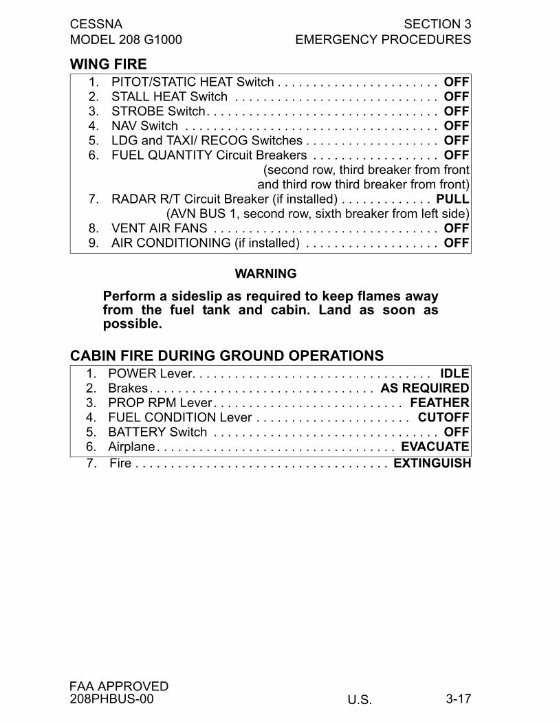
CESSNA SECTION 3MODEL 208 G1000 EMERGENCY PROCEDURES
U.S.FAA APPROVED
3-17
WING FIRE
WARNING
Perform a sideslip as required to keep flames awayfrom the fuel tank and cabin. Land as soon aspossible.
CABIN FIRE DURING GROUND OPERATIONS
7. Fire . . . . . . . . . . . . . . . . . . . . . . . . . . . . . . . . . . . . EXTINGUISH
1. PITOT/STATIC HEAT Switch . . . . . . . . . . . . . . . . . . . . . . . OFF2. STALL HEAT Switch . . . . . . . . . . . . . . . . . . . . . . . . . . . . . OFF3. STROBE Switch. . . . . . . . . . . . . . . . . . . . . . . . . . . . . . . . . OFF4. NAV Switch . . . . . . . . . . . . . . . . . . . . . . . . . . . . . . . . . . . . OFF5. LDG and TAXI/ RECOG Switches . . . . . . . . . . . . . . . . . . . OFF6. FUEL QUANTITY Circuit Breakers . . . . . . . . . . . . . . . . . . OFF
(second row, third breaker from frontand third row third breaker from front)
7. RADAR R/T Circuit Breaker (if installed) . . . . . . . . . . . . . PULL(AVN BUS 1, second row, sixth breaker from left side)
8. VENT AIR FANS . . . . . . . . . . . . . . . . . . . . . . . . . . . . . . . . OFF9. AIR CONDITIONING (if installed) . . . . . . . . . . . . . . . . . . . OFF
1. POWER Lever. . . . . . . . . . . . . . . . . . . . . . . . . . . . . . . . . . IDLE2. Brakes. . . . . . . . . . . . . . . . . . . . . . . . . . . . . . . . AS REQUIRED3. PROP RPM Lever . . . . . . . . . . . . . . . . . . . . . . . . . . . FEATHER4. FUEL CONDITION Lever . . . . . . . . . . . . . . . . . . . . . . CUTOFF5. BATTERY Switch . . . . . . . . . . . . . . . . . . . . . . . . . . . . . . . . OFF6. Airplane. . . . . . . . . . . . . . . . . . . . . . . . . . . . . . . . . . EVACUATE
208PHBUS-00
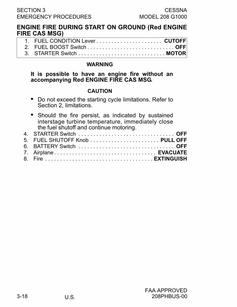
SECTION 3 CESSNAEMERGENCY PROCEDURES MODEL 208 G1000
U.S.FAA APPROVED
3-18
ENGINE FIRE DURING START ON GROUND (Red ENGINEFIRE CAS MSG)
WARNING
It is possible to have an engine fire without anaccompanying Red ENGINE FIRE CAS MSG.
CAUTION
• Do not exceed the starting cycle limitations. Refer toSection 2, limitations.
• Should the fire persist, as indicated by sustainedinterstage turbine temperature, immediately closethe fuel shutoff and continue motoring.
4. STARTER Switch . . . . . . . . . . . . . . . . . . . . . . . . . . . . . . . . OFF5. FUEL SHUTOFF Knob . . . . . . . . . . . . . . . . . . . . . . . PULL OFF6. BATTERY Switch . . . . . . . . . . . . . . . . . . . . . . . . . . . . . . . . OFF7. Airplane . . . . . . . . . . . . . . . . . . . . . . . . . . . . . . . . . . EVACUATE8. Fire . . . . . . . . . . . . . . . . . . . . . . . . . . . . . . . . . . . . EXTINGUISH
1. FUEL CONDITION Lever . . . . . . . . . . . . . . . . . . . . . . CUTOFF2. FUEL BOOST Switch . . . . . . . . . . . . . . . . . . . . . . . . . . . . . OFF3. STARTER Switch . . . . . . . . . . . . . . . . . . . . . . . . . . . . . MOTOR
208PHBUS-00
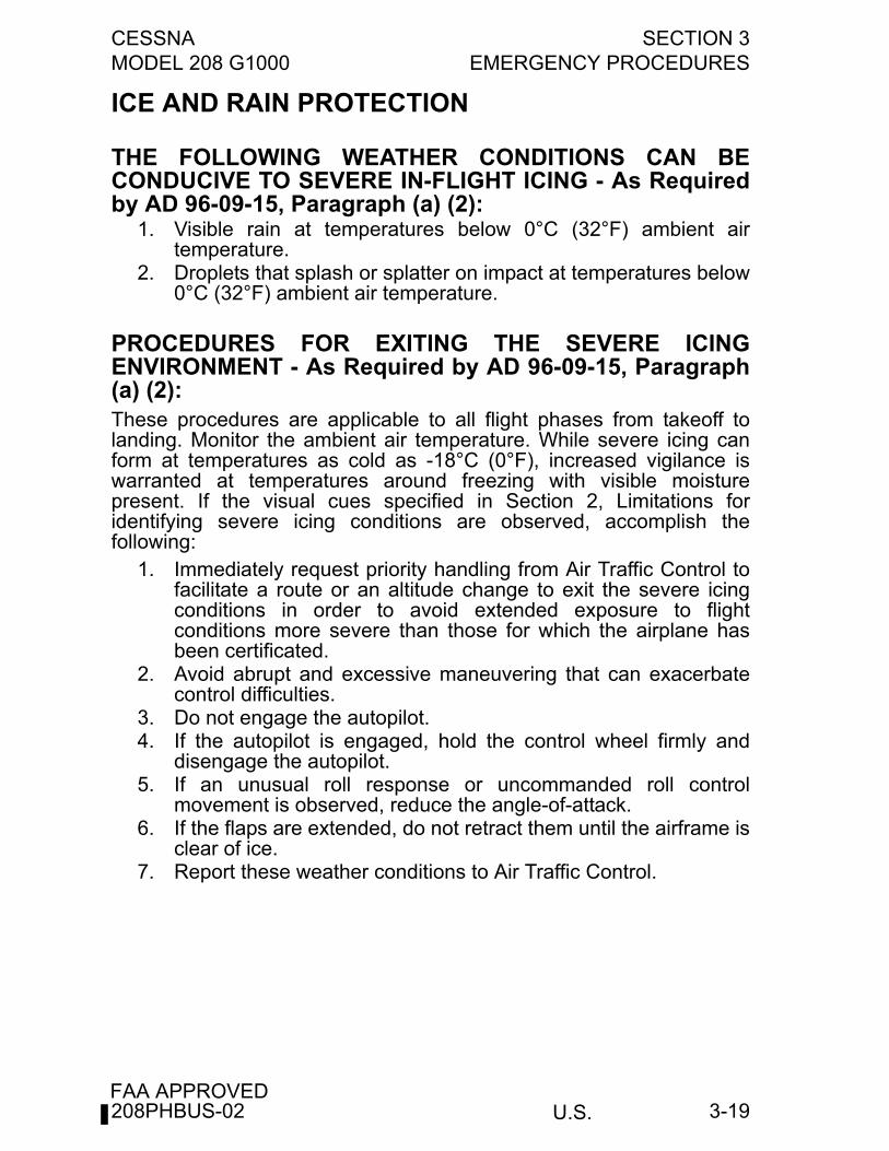
CESSNA SECTION 3MODEL 208 G1000 EMERGENCY PROCEDURES
U.S.FAA APPROVED
3-19
ICE AND RAIN PROTECTION
THE FOLLOWING WEATHER CONDITIONS CAN BECONDUCIVE TO SEVERE IN-FLIGHT ICING - As Requiredby AD 96-09-15, Paragraph (a) (2):
1. Visible rain at temperatures below 0°C (32°F) ambient airtemperature.
2. Droplets that splash or splatter on impact at temperatures below0°C (32°F) ambient air temperature.
PROCEDURES FOR EXITING THE SEVERE ICINGENVIRONMENT - As Required by AD 96-09-15, Paragraph(a) (2):These procedures are applicable to all flight phases from takeoff tolanding. Monitor the ambient air temperature. While severe icing canform at temperatures as cold as -18°C (0°F), increased vigilance iswarranted at temperatures around freezing with visible moisturepresent. If the visual cues specified in Section 2, Limitations foridentifying severe icing conditions are observed, accomplish thefollowing:
1. Immediately request priority handling from Air Traffic Control tofacilitate a route or an altitude change to exit the severe icingconditions in order to avoid extended exposure to flightconditions more severe than those for which the airplane hasbeen certificated.
2. Avoid abrupt and excessive maneuvering that can exacerbatecontrol difficulties.
3. Do not engage the autopilot.4. If the autopilot is engaged, hold the control wheel firmly and
disengage the autopilot.5. If an unusual roll response or uncommanded roll control
movement is observed, reduce the angle-of-attack.6. If the flaps are extended, do not retract them until the airframe is
clear of ice.7. Report these weather conditions to Air Traffic Control.
208PHBUS-02
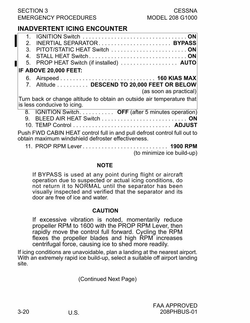
SECTION 3 CESSNAEMERGENCY PROCEDURES MODEL 208 G1000
U.S.FAA APPROVED
3-20
INADVERTENT ICING ENCOUNTER
8. IGNITION Switch. . . . . . . . . . . OFF (after 5 minutes operation)9. BLEED AIR HEAT Switch . . . . . . . . . . . . . . . . . . . . . . . . . . . ON10. TEMP Control . . . . . . . . . . . . . . . . . . . . . . . . . . . . . . . ADJUST
Push FWD CABIN HEAT control full in and pull defrost control full out toobtain maximum windshield defroster effectiveness.
11. PROP RPM Lever . . . . . . . . . . . . . . . . . . . . . . . . . . . 1900 RPM(to minimize ice build-up)
NOTE
If BYPASS is used at any point during flight or aircraftoperation due to suspected or actual icing conditions, donot return it to NORMAL until the separator has beenvisually inspected and verified that the separator and itsdoor are free of ice and water.
CAUTION
If excessive vibration is noted, momentarily reducepropeller RPM to 1600 with the PROP RPM Lever, thenrapidly move the control full forward. Cycling the RPMflexes the propeller blades and high RPM increasescentrifugal force, causing ice to shed more readily.
If icing conditions are unavoidable, plan a landing at the nearest airport.With an extremely rapid ice build-up, select a suitable off airport landingsite.
(Continued Next Page)
1. IGNITION Switch . . . . . . . . . . . . . . . . . . . . . . . . . . . . . . . . . ON2. INERTIAL SEPARATOR. . . . . . . . . . . . . . . . . . . . . . . BYPASS3. PITOT/STATIC HEAT Switch . . . . . . . . . . . . . . . . . . . . . . . . ON4. STALL HEAT Switch . . . . . . . . . . . . . . . . . . . . . . . . . . . . . . . ON5. PROP HEAT Switch (if installed) . . . . . . . . . . . . . . . . . . AUTO
IF ABOVE 20,000 FEET:6. Airspeed . . . . . . . . . . . . . . . . . . . . . . . . . . . . . . 160 KIAS MAX7. Altitude . . . . . . . . . . DESCEND TO 20,000 FEET OR BELOW
(as soon as practical)Turn back or change altitude to obtain an outside air temperature thatis less conducive to icing.
208PHBUS-01
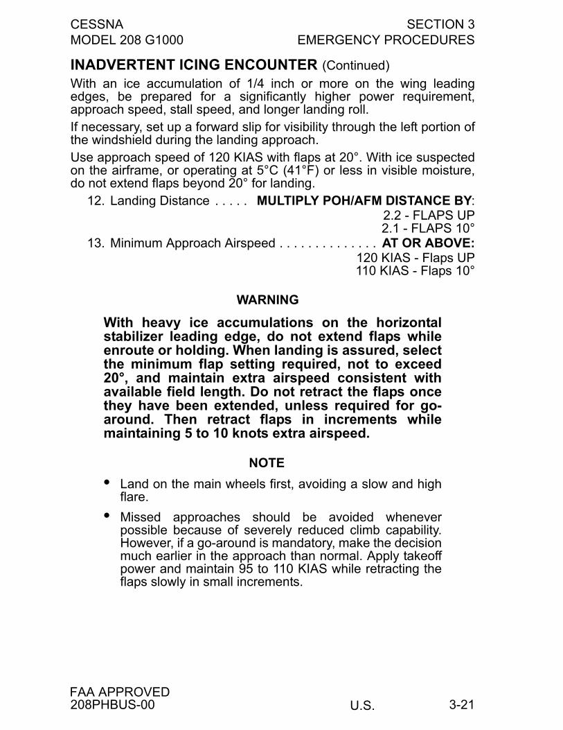
CESSNA SECTION 3MODEL 208 G1000 EMERGENCY PROCEDURES
U.S.FAA APPROVED
3-21
INADVERTENT ICING ENCOUNTER (Continued)
With an ice accumulation of 1/4 inch or more on the wing leadingedges, be prepared for a significantly higher power requirement,approach speed, stall speed, and longer landing roll.If necessary, set up a forward slip for visibility through the left portion ofthe windshield during the landing approach.Use approach speed of 120 KIAS with flaps at 20°. With ice suspectedon the airframe, or operating at 5°C (41°F) or less in visible moisture,do not extend flaps beyond 20° for landing.
12. Landing Distance . . . . . MULTIPLY POH/AFM DISTANCE BY:2.2 - FLAPS UP2.1 - FLAPS 10°
13. Minimum Approach Airspeed . . . . . . . . . . . . . . AT OR ABOVE:120 KIAS - Flaps UP110 KIAS - Flaps 10°
WARNING
With heavy ice accumulations on the horizontalstabilizer leading edge, do not extend flaps whileenroute or holding. When landing is assured, selectthe minimum flap setting required, not to exceed20°, and maintain extra airspeed consistent withavailable field length. Do not retract the flaps oncethey have been extended, unless required for go-around. Then retract flaps in increments whilemaintaining 5 to 10 knots extra airspeed.
NOTE
• Land on the main wheels first, avoiding a slow and highflare.
• Missed approaches should be avoided wheneverpossible because of severely reduced climb capability.However, if a go-around is mandatory, make the decisionmuch earlier in the approach than normal. Apply takeoffpower and maintain 95 to 110 KIAS while retracting theflaps slowly in small increments.
208PHBUS-00
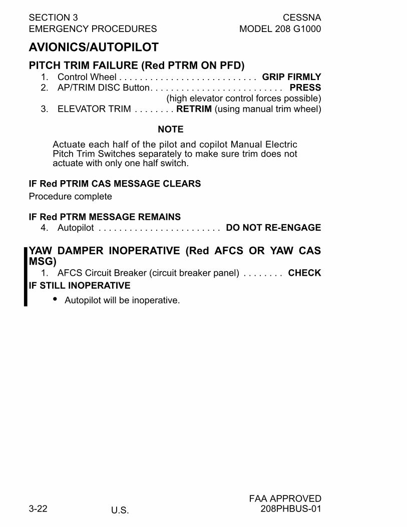
SECTION 3 CESSNAEMERGENCY PROCEDURES MODEL 208 G1000
U.S.FAA APPROVED
3-22
AVIONICS/AUTOPILOT
PITCH TRIM FAILURE (Red PTRM ON PFD)1. Control Wheel . . . . . . . . . . . . . . . . . . . . . . . . . . . GRIP FIRMLY2. AP/TRIM DISC Button. . . . . . . . . . . . . . . . . . . . . . . . . . PRESS
(high elevator control forces possible)3. ELEVATOR TRIM . . . . . . . . RETRIM (using manual trim wheel)
NOTE
Actuate each half of the pilot and copilot Manual ElectricPitch Trim Switches separately to make sure trim does notactuate with only one half switch.
IF Red PTRIM CAS MESSAGE CLEARSProcedure complete
IF Red PTRM MESSAGE REMAINS4. Autopilot . . . . . . . . . . . . . . . . . . . . . . . . DO NOT RE-ENGAGE
YAW DAMPER INOPERATIVE (Red AFCS OR YAW CASMSG)
1. AFCS Circuit Breaker (circuit breaker panel) . . . . . . . . CHECKIF STILL INOPERATIVE
• Autopilot will be inoperative.
208PHBUS-01
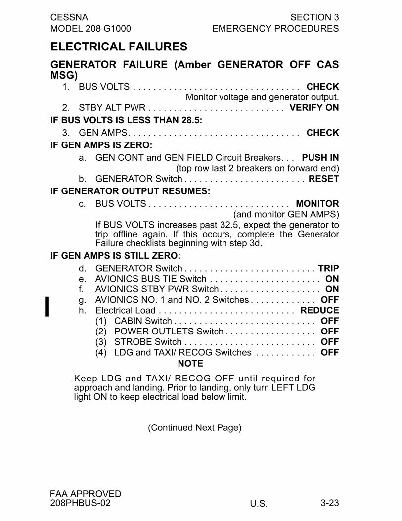
CESSNA SECTION 3MODEL 208 G1000 EMERGENCY PROCEDURES
U.S.FAA APPROVED
3-23
ELECTRICAL FAILURES
GENERATOR FAILURE (Amber GENERATOR OFF CASMSG)
1. BUS VOLTS . . . . . . . . . . . . . . . . . . . . . . . . . . . . . . . . . CHECKMonitor voltage and generator output.
2. STBY ALT PWR . . . . . . . . . . . . . . . . . . . . . . . . . . . VERIFY ONIF BUS VOLTS IS LESS THAN 28.5:
3. GEN AMPS. . . . . . . . . . . . . . . . . . . . . . . . . . . . . . . . . . CHECKIF GEN AMPS IS ZERO:
a. GEN CONT and GEN FIELD Circuit Breakers. . . PUSH IN(top row last 2 breakers on forward end)
b. GENERATOR Switch . . . . . . . . . . . . . . . . . . . . . . . . RESETIF GENERATOR OUTPUT RESUMES:
c. BUS VOLTS . . . . . . . . . . . . . . . . . . . . . . . . . . . . MONITOR(and monitor GEN AMPS)
If BUS VOLTS increases past 32.5, expect the generator totrip offline again. If this occurs, complete the GeneratorFailure checklists beginning with step 3d.
IF GEN AMPS IS STILL ZERO:d. GENERATOR Switch . . . . . . . . . . . . . . . . . . . . . . . . . . TRIPe. AVIONICS BUS TIE Switch . . . . . . . . . . . . . . . . . . . . . . ONf. AVIONICS STBY PWR Switch . . . . . . . . . . . . . . . . . . . . ONg. AVIONICS NO. 1 and NO. 2 Switches . . . . . . . . . . . . . OFFh. Electrical Load . . . . . . . . . . . . . . . . . . . . . . . . . . . REDUCE
(1) CABIN Switch . . . . . . . . . . . . . . . . . . . . . . . . . . . . OFF(2) POWER OUTLETS Switch . . . . . . . . . . . . . . . . . . OFF(3) STROBE Switch . . . . . . . . . . . . . . . . . . . . . . . . . . OFF(4) LDG and TAXI/ RECOG Switches . . . . . . . . . . . . OFF
NOTE
Keep LDG and TAXI/ RECOG OFF until required forapproach and landing. Prior to landing, only turn LEFT LDGlight ON to keep electrical load below limit.
(Continued Next Page)
208PHBUS-02
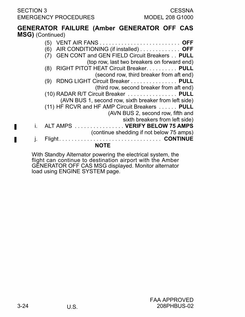
SECTION 3 CESSNAEMERGENCY PROCEDURES MODEL 208 G1000
U.S.FAA APPROVED
3-24
GENERATOR FAILURE (Amber GENERATOR OFF CASMSG) (Continued)
(5) VENT AIR FANS . . . . . . . . . . . . . . . . . . . . . . . . . . OFF(6) AIR CONDITIONING (if installed) . . . . . . . . . . . . . OFF(7) GEN CONT and GEN FIELD Circuit Breakers . . PULL
(top row, last two breakers on forward end)(8) RIGHT PITOT HEAT Circuit Breaker. . . . . . . . . . PULL
(second row, third breaker from aft end)(9) RDNG LIGHT Circuit Breaker . . . . . . . . . . . . . . . PULL
(third row, second breaker from aft end)(10) RADAR R/T Circuit Breaker . . . . . . . . . . . . . . . . PULL
(AVN BUS 1, second row, sixth breaker from left side)(11) HF RCVR and HF AMP Circuit Breakers . . . . . . PULL
(AVN BUS 2, second row, fifth andsixth breakers from left side)
i. ALT AMPS . . . . . . . . . . . . . . . . VERIFY BELOW 75 AMPS(continue shedding if not below 75 amps)
j. Flight . . . . . . . . . . . . . . . . . . . . . . . . . . . . . . . . . CONTINUE NOTE
With Standby Alternator powering the electrical system, theflight can continue to destination airport with the AmberGENERATOR OFF CAS MSG displayed. Monitor alternatorload using ENGINE SYSTEM page.
208PHBUS-02
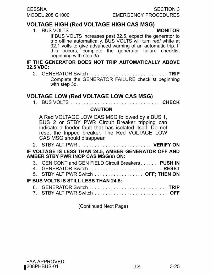
CESSNA SECTION 3MODEL 208 G1000 EMERGENCY PROCEDURES
U.S.FAA APPROVED
3-25
VOLTAGE HIGH (Red VOLTAGE HIGH CAS MSG)1. BUS VOLTS . . . . . . . . . . . . . . . . . . . . . . . . . . . . . . . MONITOR
If BUS VOLTS increases past 32.5, expect the generator totrip offline automatically. BUS VOLTS will turn red/ white at32.1 volts to give advanced warning of an automatic trip. Ifthis occurs, complete the generator failure checklistbeginning with step 3a.
IF THE GENERATOR DOES NOT TRIP AUTOMATICALLY ABOVE32.5 VDC:
2. GENERATOR Switch . . . . . . . . . . . . . . . . . . . . . . . . . . . . . TRIPComplete the GENERATOR FAILURE checklist beginningwith step 3d.
VOLTAGE LOW (Red VOLTAGE LOW CAS MSG)1. BUS VOLTS . . . . . . . . . . . . . . . . . . . . . . . . . . . . . . . . . CHECK
CAUTION
A Red VOLTAGE LOW CAS MSG followed by a BUS 1,BUS 2 or STBY PWR Circuit Breaker tripping canindicate a feeder fault that has isolated itself. Do notreset the tripped breaker. The Red VOLTAGE LOWCAS MSG should disappear.
2. STBY ALT PWR . . . . . . . . . . . . . . . . . . . . . . . . . . . VERIFY ONIF VOLTAGE IS LESS THAN 24.5, AMBER GENERATOR OFF ANDAMBER STBY PWR INOP CAS MSG(s) ON:
3. GEN CONT and GEN FIELD Circuit Breakers . . . . . . PUSH IN4. GENERATOR Switch . . . . . . . . . . . . . . . . . . . . . . . . . . . RESET5. STBY ALT PWR Switch . . . . . . . . . . . . . . . . . . OFF; THEN ON
IF BUS VOLTS IS STILL LESS THAN 24.5:6. GENERATOR Switch . . . . . . . . . . . . . . . . . . . . . . . . . . . . . TRIP7. STBY ALT PWR Switch . . . . . . . . . . . . . . . . . . . . . . . . . . . OFF
(Continued Next Page)
208PHBUS-01
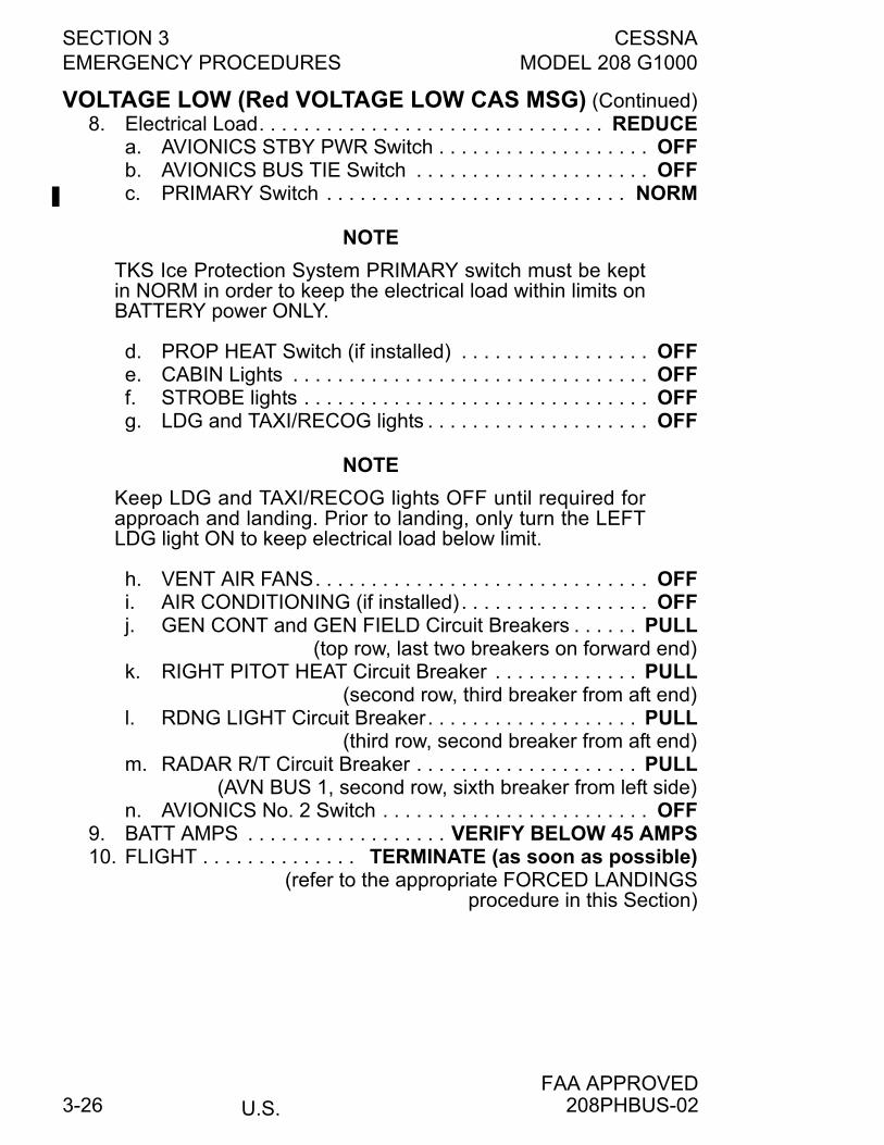
SECTION 3 CESSNAEMERGENCY PROCEDURES MODEL 208 G1000
U.S.FAA APPROVED
3-26
VOLTAGE LOW (Red VOLTAGE LOW CAS MSG) (Continued)8. Electrical Load. . . . . . . . . . . . . . . . . . . . . . . . . . . . . . . REDUCE
a. AVIONICS STBY PWR Switch . . . . . . . . . . . . . . . . . . . OFFb. AVIONICS BUS TIE Switch . . . . . . . . . . . . . . . . . . . . . OFFc. PRIMARY Switch . . . . . . . . . . . . . . . . . . . . . . . . . . . NORM
NOTE
TKS Ice Protection System PRIMARY switch must be keptin NORM in order to keep the electrical load within limits onBATTERY power ONLY.
d. PROP HEAT Switch (if installed) . . . . . . . . . . . . . . . . . OFFe. CABIN Lights . . . . . . . . . . . . . . . . . . . . . . . . . . . . . . . . OFFf. STROBE lights . . . . . . . . . . . . . . . . . . . . . . . . . . . . . . . OFFg. LDG and TAXI/RECOG lights . . . . . . . . . . . . . . . . . . . . OFF
NOTE
Keep LDG and TAXI/RECOG lights OFF until required forapproach and landing. Prior to landing, only turn the LEFTLDG light ON to keep electrical load below limit.
h. VENT AIR FANS. . . . . . . . . . . . . . . . . . . . . . . . . . . . . . OFFi. AIR CONDITIONING (if installed) . . . . . . . . . . . . . . . . . OFFj. GEN CONT and GEN FIELD Circuit Breakers . . . . . . PULL
(top row, last two breakers on forward end)k. RIGHT PITOT HEAT Circuit Breaker . . . . . . . . . . . . . PULL
(second row, third breaker from aft end)l. RDNG LIGHT Circuit Breaker. . . . . . . . . . . . . . . . . . . PULL
(third row, second breaker from aft end)m. RADAR R/T Circuit Breaker . . . . . . . . . . . . . . . . . . . . PULL
(AVN BUS 1, second row, sixth breaker from left side)n. AVIONICS No. 2 Switch . . . . . . . . . . . . . . . . . . . . . . . . OFF
9. BATT AMPS . . . . . . . . . . . . . . . . . . VERIFY BELOW 45 AMPS10. FLIGHT . . . . . . . . . . . . . . TERMINATE (as soon as possible)
(refer to the appropriate FORCED LANDINGSprocedure in this Section)
208PHBUS-02
CESSNA SECTION 3MODEL 208 G1000 EMERGENCY PROCEDURES
U.S.FAA APPROVED
3-27
ENGINE MALFUNCTIONS
LOSS OF OIL PRESSURE (Red OIL PRESS LOW CASMSG)
1. Oil Pressure Indication . . . . . . . . . . . . . . . . . . . . . . . MONITOR
CAUTION
If oil pressure indications confirm warning CAS MSG,proceed in accordance with Engine Failures checklistsor at the discretion of the pilot and consistent withsafety, continue engine operation in preparation for anemergency landing as soon as possible.
FUEL CONTROL UNIT MALFUNCTION IN THEPNEUMATIC OR GOVERNOR SECTIONS (Engine PowerRolls Back To Idle)
CAUTION
The EMERGENCY POWER lever overrides normal fuelcontrol functions and results in the direct operation ofthe fuel metering valve. Utilize slow and smoothmovement of the EMERGENCY POWER lever to avoidengine surges, and/or exceeding ITT, Ng, and torquelimits.
EMERGENCY POWER LEVER NOT STOWED (Red EMERGPWR LVR CAS MSG)
1. EMERGENCY POWER Lever . . . . . . . . . . . VERIFY NORMAL
1. POWER Lever . . . . . . . . . . . . . . . . . . . . . . . . . . . . . . . . . IDLE2. EMERGENCY POWER Lever . . . . . . . . . . . . . . . . . . . . . . USE
(maintain 65% Ng minimum during flight)
208PHBUS-01
SECTION 3 CESSNAEMERGENCY PROCEDURES MODEL 208 G1000
U.S.FAA APPROVED
3-28
FUEL SYSTEM
FUEL FLOW INTERRUPTION TO FUEL RESERVOIR (RedRSVR FUEL LOW CAS MSG)
4. If Red RSVR FUEL LOW CAS MSG remains and there is usablefuel in the wing tanks:a. Carefully monitor engine indications and Amber FUEL
PRESS LOW CAS MSG for signs of fuel starvation.b. Land as soon as possible and determine cause of Red
RSVR FUEL LOW warning.
WARNING
If there are signs of fuel starvation, prepare for aforced landing (as described in Emergency LandingWithout Engine Power).
FUEL TANK SELECTOR OFF DURING ENGINE START(Red FUEL SELECT OFF CAS MSG And Both FuelSelector Warning Horns Activated)
FUEL LEVEL LOW AND SINGLE FUEL SELECTOR OFF(Red FUEL SELECT OFF and Amber L, R, OR L-R FUELLOW CAS MSG(s)) and/or BOTH FUEL TANK SELECTORSOFF (Red FUEL SELECT OFF CAS MSG AND ONE FUELWARNING HORN ACTIVATED)
1. FUEL TANK SELECTORS . . . . . . . . . . . . . . . . . . . . BOTH ON2. Fuel Balance . . . . . . . . . . . . . . . . . . . . . . . . . . . . . . . MONITOR
Maximum 200 pounds imbalance.
1. FUEL TANK SELECTORS . . . . . . . . . . . . . . . . . . . . BOTH ON2. IGNITION Switch. . . . . . . . . . . . . . . . . . . . . . . . . . . . . ON3. FUEL BOOST Switch . . . . . . . . . . . . . . . . . . . . . . . . . . . . . ON
1. FUEL TANK SELECTORS . . . . . . . . . . . . . . . . . . . . BOTH ON
208PHBUS-01
CESSNA SECTION 3MODEL 208 G1000 EMERGENCY PROCEDURES
U.S.FAA APPROVED
3-29
START CONT AND/OR FUEL SELECT WARN CIRCUITBREAKER(S) TRIPPED (Red FUEL SELECT OFF CASMSG)
1. Tripped Circuit Breaker(s). . . . . . . . . . . . . . . . . . . . . . . . RESET
NOTE
With either the START CONT or FUEL SELECT WARNCircuit Breaker tripped, the Red FUEL SELECT OFF CASMSG will be displayed and the FUEL SELECT WARNINGHORNS will be inoperative.
CAUTION
Do not reset circuit breakers more than once and onlyafter a 2 minute cool off period.
208PHBUS-01

SECTION 3 CESSNAEMERGENCY PROCEDURES MODEL 208 G1000
U.S.FAA APPROVED
3-30
EXPANDED EMERGENCY
ENGINE FAILUREIf an engine failure occurs during the takeoff roll, the most importantthing to do is stop the airplane on the remaining runway. Those extraitems on the checklist will provide added safety after a failure of thistype. Prompt lowering of the nose to maintain airspeed and establish a glideattitude is the first response to an engine failure after takeoff.Feathering the propeller substantially reduces drag, thereby providingincreased glide distance. In most cases, the landing should be plannedstraight ahead with only small changes in direction to avoidobstructions. Altitude and airspeed are seldom sufficient to execute a180° gliding turn necessary to return to the runway. The checklistprocedures assume that adequate time exists to secure the fuel andelectrical systems prior to touchdown. After an engine failure in flight, the best glide speed, as shown in Figure3-1, should be established as quickly as possible. Propeller featheringis dependent on existing circumstances and is at the discretion of thepilot. Maximum RPM selection will provide increased gas generatorwindmilling speed for emergency restarts in the event of a starterfailure. On the other hand, to obtain the maximum glide, the propellermust be feathered.
(Continued Next Page)
208PHBUS-01
CESSNA SECTION 3MODEL 208 G1000 EMERGENCY PROCEDURES
U.S.FAA APPROVED
3-31
ENGINE FAILURE (Continued)
While gliding toward a suitable landing area, an effort should be madeto identify the cause of the power loss. An engine failure might beidentified by abnormal temperatures, mechanical noises or highvibration levels in conjunction with the power loss. A flameout will benoticed by a drop in ITT, torque and% Ng.
CAUTION
Do not attempt to restart an engine that is definitelyknown to have failed.
A flameout can result from the engine running out of fuel, or by unstableengine operation. Unstable engine operation such as a compressorsurge (possible due to a bleed valve malfunction) can be identifiable byan audible popping noise just before flameout. Once the fuel supplyhas been restored to the engine or cause of unstable engine operationeliminated, the engine can be restarted.The best airstart technique is to initiate the relight procedureimmediately after a flameout occurs, provided the pilot is certain thatthe flameout was not the result of some malfunction that might make ithazardous to attempt a relight.Regardless of airspeed or altitude, there is always the possibility thatthe engine can light up successfully just as soon as the ignition isturned on. In an emergency, turn on the ignition just as soon aspossible after flameout, provided the gas generator speed has notdropped below 50%. Under these circumstances, it is not necessary toshut off the fuel or feather the propeller. The POWER lever, however,should be retarded to IDLE position.
CAUTION
The pilot should determine the reason for power lossbefore attempting an airstart.
If a flameout has occurred and the gas generator speed has droppedbelow 50%, the FUEL CONDITION lever should be moved to theCUTOFF position before an airstart is attempted.
(Continued Next Page)
208PHBUS-01
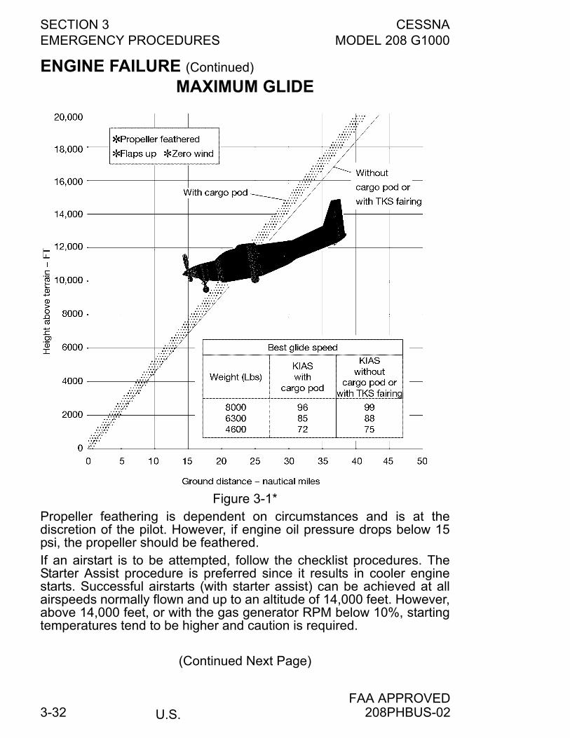
SECTION 3 CESSNAEMERGENCY PROCEDURES MODEL 208 G1000
U.S.FAA APPROVED
3-32
ENGINE FAILURE (Continued)
Propeller feathering is dependent on circumstances and is at thediscretion of the pilot. However, if engine oil pressure drops below 15psi, the propeller should be feathered.If an airstart is to be attempted, follow the checklist procedures. TheStarter Assist procedure is preferred since it results in cooler enginestarts. Successful airstarts (with starter assist) can be achieved at allairspeeds normally flown and up to an altitude of 14,000 feet. However,above 14,000 feet, or with the gas generator RPM below 10%, startingtemperatures tend to be higher and caution is required.
(Continued Next Page)
MAXIMUM GLIDE
Figure 3-1*
208PHBUS-02
CESSNA SECTION 3MODEL 208 G1000 EMERGENCY PROCEDURES
U.S.FAA APPROVED
3-33
ENGINE FAILURE (Continued)
CAUTION
The FUEL CONDITION lever can be movedmomentarily to CUTOFF and then back to LOW IDLE ifovertemperature tendencies are encountered. Thisreduces the flow of fuel to the combustion chamber.
If the engine starter is inoperative, follow the No Starter Assist checklistprocedures for an airstart.
CAUTION
• If a rise in Ng and ITT are not indicated within 10seconds, place FUEL CONDITION lever to cutoffand abort start. Refer to Emergency ProceduresEngine Failure During Flight and EmergencyLanding Without Engine Power.
• Emergency airstarts can be attempted below 10%Ng and outside the normal airspeed envelope, butITT should be c losely moni tored. the FUELCONDITION lever can be moved alternately to cutoffand then back to low idle i f overtemperaturetendencies are encountered.
• Do not attempt an airstart without starter assist with0% Ng.
208PHBUS-01
SECTION 3 CESSNAEMERGENCY PROCEDURES MODEL 208 G1000
U.S.FAA APPROVED
3-34
FORCED LANDINGSIf all attempts to restart the engine fail and a forced landing is imminent,select a suitable field and prepare for the landing as discussed underthe Emergency Landing Without Engine Power checklist.Before attempting an off-airport landing with engine power available,one should fly over the landing area at a safe but low altitude to inspectthe terrain for obstructions and surface conditions, proceeding asdiscussed in the Precautionary Landing With Engine Power checklist.
NOTE
The overhead fuel tank selectors control shutoff valves atthe wing fuel tank outlets. To minimize the possibility of afire, these selectors can be set to the OFF position duringthe final phase of an approach to an “off-airport” landing.With the selectors turned OFF, there is adequate fuel in thefuel reservoir tank for 3 minutes of maximum continuouspower operation or approximately 9 minutes idle poweroperation. A warning horn will sound with both fuelselectors turned OFF. If the noise of the warning horn is toodistracting, it can be silenced by pulling the START CONTcircuit breaker.
WARNING
If the precautionary landing is aborted, turn the fueltank selectors to the on position after initiating thebalked landing.
DITCHINGPrepare for ditching by securing or jettisoning heavy objects located inthe baggage area and collect folded coats for protection of occupants’faces at touchdown. Transmit Mayday message on 121.5 MHz givinglocation and intentions and squawk 7700. Avoid a landing flarebecause of difficulty in judging height over a water surface.
208PHBUS-01
CESSNA SECTION 3MODEL 208 G1000 EMERGENCY PROCEDURES
U.S.FAA APPROVED
3-35
LANDING WITHOUT ELEVATOR CONTROLUsing power lever and elevator trim control, trim for approximately 500fpm descent with 20° flaps at 85 KIAS. Then control the glide angle byadjusting power. If required, make small trim changes to maintainapproximately 85 KIAS as power is adjusted during the approach. The landing flare can be accomplished by a gentle power reductionaccompanied by nose up trim. At forward C.G. loadings, it can benecessary to make a small power increase in the final flare stage tobring the nose up and prevent touchdown on the nose first. Aftertouchdown, move the POWER lever to idle.
SMOKE AND FIREIn the event a fire is encountered, the following information will behelpful in dealing with the emergency as quickly and safely as possible.The preflight checklist in Section 4 is provided to aid the pilot indetecting conditions which could contribute to an airplane fire. As a firerequires a combustible material, oxygen and a source of ignition, closepreflight inspection should be given to the engine compartment and theunderside of the wing and fuselage. Leaks in the fuel or oil systems canlead to a ground or in-flight fire.
WARNING
Flight should not be attempted with known fuel oroil leaks. The presence of fuel or unusual oil stainscan be an indication of system leaks and should becorrected prior to flight.
Probable causes of an engine fire are a malfunction of the fuel controlunit and improper starting procedures. Improper procedures such asstarting with the EMERGENCY POWER lever out of NORMAL positionor introducing fuel into the engine when gas generator speed is below10% RPM will cause a hot start which can result in an engine fire. In theevent that this occurs, proceed in accordance with the Engine FireDuring Start On Ground checklist.If an airplane fire is discovered on the ground or during takeoff, but priorto committed flight, the airplane should be stopped and evacuated assoon as practical.
(Continued Next Page)
208PHBUS-01
SECTION 3 CESSNAEMERGENCY PROCEDURES MODEL 208 G1000
U.S.FAA APPROVED
3-36
SMOKE AND FIRE (Continued)
Engine fires originating in flight must be controlled as quickly aspossible in an attempt to prevent major structural damage. Immediatelyshut off all fuel to the engine and shut down the engine. Close the cabinheat firewall shutoff control and forward side vents to avoid drawing fireinto the cabin, open the overhead vents, extend 10° to FULL flaps andslow down to 80-85 KIAS. This provides a positive cabin pressure inrelation to the engine compartment. An engine restart should not beattempted.An open foul weather window produces a low pressure in the cabin. Toavoid drawing the fire into the cabin, the foul weather window should bekept closed.A fire or smoke in the cabin should be controlled by identifying andshutting down the faulty system. Smoke can be removed by openingthe cabin ventilation controls. When the smoke is intense, the pilot canchoose to expel the smoke through the foul weather window. The foulweather window should be closed immediately if the fire becomes moreintense when the window is opened.The initial indication of an electrical fire is usually the odor of burninginsulation. The checklist for this problem should result in elimination ofthe fire.
EMERGENCY OPERATION IN CLOUDS If the vacuum pump fails in flight, the standby attitude indicator will notbe accurate. The pilot must rely on the attitude and heading information(from the AHRS) shown on the PFD indicators. With valid HDG or GPS/NAV inputs, autopilot operation will not be affected.
If a single AHRS unit fails in flight (red X’s shown through the PFDattitude and heading indicators), the pilot must rely on the cross-sideAHRS for attitude and heading information.
The autopilot will not operate if a single AHRS unit fails. The pilot mustmanually fly the airplane with crosside AHRS input. Refer to Section 7,Airplane and Systems Description, for additional details on autopilotoperations.
The following instructions assume a dual AHRS failure and that thepilot is not very proficient at instrument flying.
208PHBUS-02
CESSNA SECTION 3MODEL 208 G1000 EMERGENCY PROCEDURES
U.S.FAA APPROVED
3-37
EXECUTING A 180° TURN IN CLOUDS (AHRS FAILURE)
Upon inadvertently entering the clouds, an immediate turn to reversecourse and return to VFR conditions should be made as follows:
DUAL AHRS FAILURE1. Note the non-stabilized magnetic compass heading.2. Set rudder trim to the neutral position.3. Using the standby attitude indicator, initiate a 15° bank left turn.
Keep feet off rudder pedals. Maintain altitude and 15° bankangle. Continue the turn for 60 seconds, then roll back to levelflight.
4. When the compass card becomes sufficiently stable, check theaccuracy of the turn by verifying that the compass headingapproximates the reciprocal of the original heading.
5. If necessary, adjust the heading by keeping the wings level andusing the rudder to make skidding turns (the compass will readmore accurately) to complete the course reversal.
6. Maintain altitude and airspeed by cautious application ofelevator control. Keep the roll pointer and index aligned andsteer only with rudder.
EMERGENCY DESCENT THROUGH CLOUDS (AHRSFAILURE)
When returning to VFR flight after a 180° turn is not practical, a descentthrough the clouds to VFR conditions below can be appropriate. Ifpossible, obtain an ATC clearance for an emergency descent throughthe clouds.
DUAL AHRS FAILURE
Choose an easterly or westerly heading to minimize non-stabilizedmagnetic compass card sensitivity. Occasionally check the compassheading and make minor corrections to hold an approximate course.The autopilot will not operate if the AHRS unit fails. The pilot mustmanually fly the airplane without AHRS input.
(Continued Next Page)
208PHBUS-01
SECTION 3 CESSNAEMERGENCY PROCEDURES MODEL 208 G1000
U.S.FAA APPROVED
3-38
DUAL AHRS FAILURE (Continued)
Before descending into the clouds, prepare for a stabilized descent asfollows:
1. Set rudder trim to neutral position.2. Turn pitot heat on.3. Set power for a 500 to 800 feet per minute rate of descent.4. Set the elevator trim for a stabilized descent at 115 KIAS.5. Use the standby attitude indicator roll pointer and index to keep
wings level.6. Check trend of compass card movement and make cautious
corrections with rudder to stop the turn.7. Upon breaking out of clouds, resume normal cruising flight.
RECOVERY FROM SPIRAL DIVE IN THE CLOUDS (AHRSFAILURE)
DUAL AHRS FAILURE
If a spiral is entered while in the clouds, continue as follows:1. Retard POWER lever to idle position.2. Remove feet from rudder pedals.3. Stop turn by carefully leveling the wings using aileron control to
align the roll index and roll pointer of the standby attitudeindicator.
4. Cautiously apply elevator back pressure to slowly reduce theairspeed to 115 KIAS.
5. Adjust the elevator trim control to maintain an 115 KIAS glide.6. Set rudder trim to neutral position.7. Use aileron control to maintain wings level (keep roll pointer and
index aligned) and constant heading. 8. Resume EMERGENCY DESCENT THROUGH THE CLOUDS
procedure. 9. Upon breaking out of clouds, resume normal cruising flight.
208PHBUS-01
CESSNA SECTION 3MODEL 208 G1000 EMERGENCY PROCEDURES
U.S.FAA APPROVED
3-39
SPINSIntentional spins are prohibited in this airplane. Should an inadvertentspin occur, the following recovery technique can be used.
1. RETARD POWER LEVER TO IDLE POSITION.2. PLACE AILERONS IN NEUTRAL POSITION.3. APPLY AND HOLD FULL RUDDER OPPOSITE TO THE
DIRECTION OF ROTATION.4. IMMEDIATELY AFTER THE RUDDER REACHES THE STOP,
MOVE THE CONTROL WHEEL BRISKLY FORWARD FARENOUGH TO BREAK THE STALL. Full down elevator will berequired at aft center of gravity loadings to assure optimumrecoveries.
5. HOLD THESE CONTROL INPUTS UNTIL ROTATION STOPS.Premature relaxation of the control inputs may extend therecovery.
6. AS ROTATION STOPS, NEUTRALIZE RUDDER AND MAKE ASMOOTH RECOVERY FROM THE RESULTING DIVE.
208PHBUS-02
SECTION 3 CESSNAEMERGENCY PROCEDURES MODEL 208 G1000
U.S.FAA APPROVED
3-40
ENGINE MALFUNCTIONS
LOSS OF OIL PRESSUREThe complete loss of oil pressure, as evidenced by the Red OILPRESS LOW CAS MSG and confirmed by the oil pressure indicationreading, implies that the pilot will eventually lose control of the propelleras the propeller springs and counterweights drive the propeller bladesinto feather. Also, the engine will eventually seize. Therefore, if the pilotelects to continue to operate the engine after loss of oil pressure,engine and propeller operation should be closely monitored forindication of the onset of propeller feathering or engine seizure and theengine failure checklist should be completed at that time. Operation of the engine at a reduced power setting (preferably at theminimum power required for the desired flight regime) will generallyprolong the time to loss of engine/propeller thrust.Operation of the engine with the oil pressure in the yellow band is notconsidered critical, but is a cause for concern and should be toleratedonly for the completion of the flight. Continued monitoring of the oilpressure gauge will provide an early indication of dropping oil pressuredue to insufficient oil supply or a malfunctioning oil pump, and will givethe pilot additional time to divert to a suitable emergency landing areawith the engine operating.
208PHBUS-01
CESSNA SECTION 3MODEL 208 G1000 EMERGENCY PROCEDURES
U.S.FAA APPROVED
3-41
FUEL CONTROL UNIT MALFUNCTION IN THEPNEUMATIC OR GOVERNOR SECTIONSA malfunction in the pneumatic or governor sections of the fuel controlunit can cause engine power to decrease to minimum flow idle.Symptoms of this type failure would be an ITT indication in the typicalidle range of 500°C to 600°C, Ng of 48% or above (increases withaltitude), and no engine response to POWER lever movement. If thistype of malfunction has occurred, the EMERGENCY POWER lever(fuel control manual override) can be used to restore engine power. Touse the manual override system, place the POWER lever at its IDLEposition and move the EMERGENCY POWER lever forward of its IDLEgate and advance as required.
CAUTION
When using the fuel control manual override system,engine response can be more rapid than when usingthe POWER lever. Utilize slow and smooth movementof the EMERGENCY POWER lever to avoid enginesurges, and/or exceeding ITT, Ng, and torque limits.
NOTE
• When using EMERGENCY POWER lever, monitor gasgenerator RPM when reducing power near idle, to keepit from decreasing below 65% in flight.
• The EMERGENCY POWER lever can have a deadband, such that no engine response is observed duringthe initial forward travel from the IDLE position.
EMERGENCY POWER LEVER NOT STOWEDThe Red EMERG PWR LVR CAS message was designed to alert thepilot of the Emergency Power Lever position prior to and during theengine start sequence. If the Emergency Power Lever is moved fromthe NORMAL position at any time with the engine running, no CASmessage will be displayed.
208PHBUS-01
SECTION 3 CESSNAEMERGENCY PROCEDURES MODEL 208 G1000
U.S.FAA APPROVED
3-42
FUEL SYSTEM MALFUNCTION/INADVERTENTFUEL FLOW INTERRUPTION PROCEDURESFuel flows by gravity from the wing tanks, through fuel tank shutoffvalves at the inboard end of each wing tank, and on to the reservoirlocated under the center cabin floorboard. After engine start, the mainejector pump (located in the reservoir) provides fuel to the engine-driven fuel pump at approximately 10 psi.If the main ejector pump should malfunction, a pressure switch willactivate the Amber FUEL PRESS LOW CAS MSG as well as turn onthe auxiliary boost pump (when the FUEL BOOST Switch is in theNORM position) anytime the fuel pressure drops below approximately4.75 psi.Anytime the level of fuel in the reservoir drops to approximately one halffull, the Red RSVR FUEL LOW CAS MSG will illuminate. If this occurs,the pilot should immediately verify that both FUEL TANK SELECTORS(located in the overhead panel) are ON and turn on the ignition andFUEL BOOST Switches.
WARNING
There is only enough fuel in the reservoir forapproximately 1-1/2 minutes of engine operation atmaximum continuous power after illumination ofthe Red RESERVOIR FUEL LOW CAS MSG.
If the FUEL TANK SELECTORS have been left off, turning them on willquickly fill the reservoir and extinguish the Red RSVR FUEL LOW CASMSG. Once the cause of the Red RSVR FUEL LOW condition hasbeen determined and corrected (CAS MSG extinguished), the ignitionand FUEL BOOST Switches can be returned to their NORM positions.A fuel selector off warning system advises the pilot if both fuel tankselectors are in the OFF position before engine start, if either fuel tankselector is OFF during engine start, or if one FUEL TANK SELECTORis OFF and the fuel level in the tank being used drops belowapproximately 25 gallons. The warning system includes a Red CASMSG labeled FUEL SELECT OFF and two warning horns. If the FUELSELECT WARN circuit breaker has popped or the START CONT circuitbreaker has been pulled (possibly for ground maintenance), the RedFUEL SELECT OFF CAS MSG will be illuminated even with both FUELTANK SELECTORS in the ON position. This is a warning to the pilotthat the fuel selector off warning system has been deactivated. SeeSection 7 for further details on the fuel selector off warning system.
208PHBUS-01
CESSNA SECTION 3MODEL 208 G1000 EMERGENCY PROCEDURES
U.S.FAA APPROVED
3-43
ELECTRICAL FAILURES
GENERATOR OR MAIN BUS MALFUNCTIONSIllumination of the VOLTAGE LOW CAS MSG is a warning that thepower distribution bus voltage is low enough to start discharging thebattery. BUS VOLTS reading is used to verify the low bus voltage. A lowor zero reading of the GEN AMPS confirms that the charge isinsufficient or generator output current is zero. If the GENERATOROFF CAS MSG is illuminated, it indicates that the generator contactorhas disconnected the generator from the power distribution bus. Themost likely causes of a generator trip (disconnection) are line surges,tripped circuit breakers or accidental switch operation. In these cases,follow the checklist procedures to restore generator operation.The airplane is equipped with two starter contactors. One is used forstarts on external power and the other for battery starts. If eithercontactor does not open after reaching approximately 46% Ng, theamber STARTER ON CAS MSG will remain illuminated. In most caseswhen this occurs, the generator will not transfer to the generator mode,and the GENERATOR OFF CAS MSG will remain illuminated. Underthese conditions, it will be necessary to shut down the engine usingchecklist procedures and correct the malfunction prior to flight.Illumination of the Amber GENERATOR AMPS CAS MSG indicates 1of 2 conditions:
1. The current load on the generator is above its rated value forthat flight condition. The pilot should reduce the electrical load,or change flight conditions as noted in the 300 Amp StarterGenerator supplement.
2. The reverse current protection of the GCU has failed. If the GENAMPS is below -10 amps the pilot should disconnect thegenerator from the electrical system by tripping theGENERATOR Switch.
The electrical power distribution system consists of a primary powerdistribution bus in the engine compartment which receives power fromthe battery and the generator, and two (No. 1 and No. 2) main powerbuses located in the circuit breaker panel. The main buses are eachconnected to the power distribution bus by three feeder cables. Eachfeeder cable is protected by a fuse link and a circuit breaker. Thismultiple feeder system provides automatic isolation of a feeder cableground fault. If one of the three 30-amp feeder circuit breakers on eitherbus opens, it should be assumed that a feeder cable ground fault hasbeen isolated, and attempted resetting of these breakers prior totroubleshooting is not recommended. The electrical load on theaffected bus should be maintained below the remaining 60-amperecapacity.
208PHBUS-02
SECTION 3 CESSNAEMERGENCY PROCEDURES MODEL 208 G1000
U.S.FAA APPROVED
3-44
LOSS OF ELECTRICAL POWERThe design of the electrical power system, due to the self-excitingfeature of the generator and the multiple protected busing system,minimizes the possibility of a complete electrical power loss. However,a fault to ground (airframe) on the generator or battery cables can beidentified by one or more of the following: illumination of theGENERATOR OFF CAS MSG, sudden dimming of lights, contactorchattering, circuit breaker tripping, or arching noises. Monitoring GENAMPS, ALT AMPS, BAT AMPS, and BUS VOLTS on the ELECTRICALsection of the EIS Systems page will provide further informationconcerning the location of the fault, or the system affected by the fault.In the event of the above indications, the portion of the systemcontaining the fault should be isolated. Following the checklistprocedures for Generator Failure should result in restoration ofelectrical power to the distribution buses. The electrical section of theEIS Systems page should be monitored to assure that ground faultcurrents have been shut off and the capacity of the remaining powersource(s) is not exceeded.
PARTIAL AVIONICS POWER FAILUREAvionics power is supplied to the No. 1 and No. 2 avionics buses fromthe power distribution bus in the engine compartment through separateprotected feeder cables. In the event of a feeder cable failure, bothavionics buses can be connected to the remaining feeder by closing theguarded AVIONICS BUS TIE Switch. If a ground fault has occurred onone feeder, it will be necessary to verify the avionics power switch/breaker associated with the affected feeder is off before the AVIONICSBUS TIE Switch will restore power to both avionics buses. Themaximum avionics load with one feeder should be limited to 30amperes. Nonessential avionics equipment should be turned off.
STANDBY ELECTRICAL SYSTEM MALFUNCTIONSAn operational check of the standby electrical system is performed byfollowing the Normal Procedures, Before Takeoff checklist. With thegenerator supplying the electrical load and the STBY ALT PWR SwitchON, both the Amber STBY PWR ON CAS MSG and STBY PWR INOPCAS MSG, should be extinguished.The ALT AMPS should indicate zero amps. If the STBY PWR INOPCAS MSG is illuminated, it indicates that the alternator has no output. Ifa line voltage surge or temporary condition has tripped the ACU(alternator control unit), then cycling the STBY ALT PWR Switch toOFF, then back ON, can reset the ACU and restore standby power.
(Continued Next Page)
208PHBUS-01
CESSNA SECTION 3MODEL 208 G1000 EMERGENCY PROCEDURES
U.S.FAA APPROVED
3-45
STANDBY ELECTRICAL SYSTEM MALFUNCTIONS(Continued)
If, due to a power system malfunction, the standby electrical system iscarrying part of the electrical load (more than 10 amps), the STBY PWRON CAS MSG will be illuminated and the ALT AMPS in the EISSystems page will indicate the amount of current being supplied by thestandby electrical system.To attempt to restore main power, refer to the Section 3 emergencyprocedures for Generator Failure. If this attempt is successful, thestandby electrical system will revert to its normal no-load condition andthe STBY PWR ON CAS MSG will extinguish. If main electrical powercannot be restored, reduce nonessential loads as necessary to remainwithin the 75-amp capability of the standby electrical system. Loads inexcess of this capability will be indicated by an Amber ALTNR AMPSCAS MSG.If the reverse current protection of the ACU fails, an Amber ALTNRAMPS CAS MSG will display when the reverse current is detected tobe less than -8 amps. The pilot should disconnect the standbyalternator by turning the STBY ALT PWR Switch OFF.
EMERGENCY EXITSUse of the crew entry doors, the passenger entry doors, and the cargodoors for emergency ground egress from the Standard 208B isillustrated in Figure 3-2. Emergency ground egress from theCargomaster is accomplished by exiting the airplane through the leftand right crew entry doors as shown in Figure 3-2.
WARNING
• Do not attempt to exit the Cargomaster throughthe cargo doors. Since the inside of the upperdoor has no handle, exit from the airplanethrough these doors is not possible.
• When exiting the airplane, avoid the propellerarea.
(Continued Next Page)
208PHBUS-01
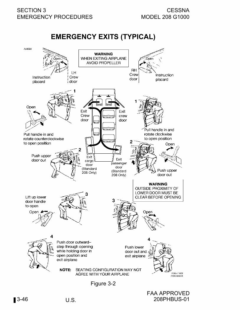
SECTION 3 CESSNAEMERGENCY PROCEDURES MODEL 208 G1000
U.S.FAA APPROVED
3-46
EMERGENCY EXITS (TYPICAL)
Figure 3-2
208PHBUS-01
CESSNA SECTION 3MODEL 208 G1000 ABNORMAL PROCEDURES
U.S.FAA APPROVED
3-47
ABNORMAL PROCEDURES
TABLE OF CONTENTSPage
Abnormal Landing . . . . . . . . . . . . . . . . . . . . . . . . . . . . . . . . . . . . . .3-51Landing with Flat Main Tire . . . . . . . . . . . . . . . . . . . . . . . . . . . . .3-51Landing with Flat Nose Tire. . . . . . . . . . . . . . . . . . . . . . . . . . . . .3-51
Avionics/Autopilot. . . . . . . . . . . . . . . . . . . . . . . . . . . . . . . . . . . . . . .3-52Aileron Mistrim (AIL OR AIL Indication PFD) . . . . . . . . . . . .3-52Elevator Mistrim (ELE OR ELE Indication PFD) . . . . . . . . . . .3-52Rudder Mistrim (RUD OR RUD Indication PFD) . . . . . . . . .3-53Altitude Miscompare
(Amber ALT MISCOMP Indication PFD) . . . . . . . . . . . . . . . . .3-53Airspeed Miscompare
(Amber IAS MISCOMP Indication PFD) . . . . . . . . . . . . . . . . .3-55Pitch/Roll/Heading Miscompare
(Amber PIT/ROL/HDG MISCOMP Indication PFD) . . . . . . . .3-57Display Unit Failure . . . . . . . . . . . . . . . . . . . . . . . . . . . . . . . . . . .3-58Dual GPS Failure
(Amber “DR” or “LOI” on HSI Indication PFD) . . . . . . . . . . . .3-59Audio Panel Failure. . . . . . . . . . . . . . . . . . . . . . . . . . . . . . . . . . .3-60Loss of Radio Tuning Functions . . . . . . . . . . . . . . . . . . . . . . . . .3-61Transponder Failure . . . . . . . . . . . . . . . . . . . . . . . . . . . . . . . . . .3-61Failed Airspeed, Altitude, and/or Vertical Speed
(Red “X” on PFD Airspeed, Altitude,and/or Vertical Speed Indicators). . . . . . . . . . . . . . . . . . . . . . .3-61
Failed Attitude and/or Heading (Attitude Failand/or Red “X” over Heading Display on PFD) . . . . . . . . . . . .3-62
Loss of Navigation Data (Lateral Deviation Barnot Present and/or Glideslope Index Clears). . . . . . . . . . . . . .3-64
Inaccurate Overspeed Warning. . . . . . . . . . . . . . . . . . . . . . . . . .3-64Inaccurate Flight Director Display . . . . . . . . . . . . . . . . . . . . . . . .3-65Both PFDs Displaying Same ADC (Amber BOTH ON
ADC 1/2 CAS MSG). . . . . . . . . . . . . . . . . . . . . . . . . . . . . . . . .3-65Both PFDs Displaying Same AHRS (Amber BOTH ON
AHRS 1/2 CAS MSG) . . . . . . . . . . . . . . . . . . . . . . . . . . . . . . .3-66Both PFDs Displaying Same GPS (Amber BOTH ON
GPS 1/2 CAS MSG) . . . . . . . . . . . . . . . . . . . . . . . . . . . . . . . 3-66(Continued Next Page)
208PHBUS-02
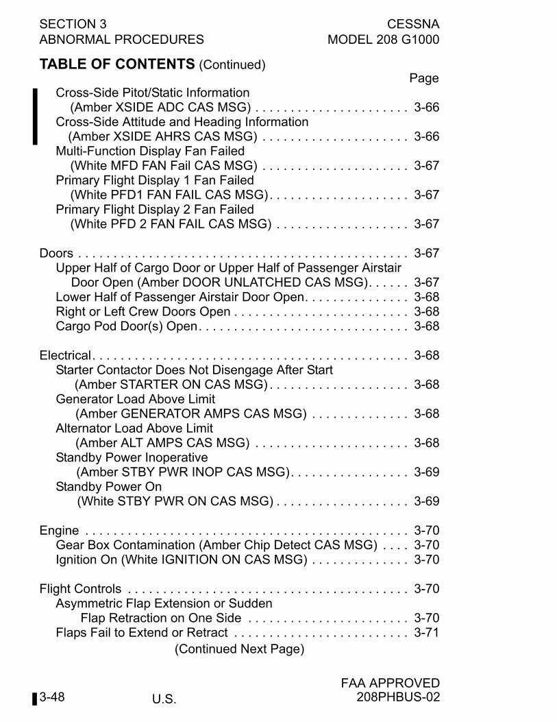
U.S.
SECTION 3 CESSNAABNORMAL PROCEDURES MODEL 208 G1000
FAA APPROVED3-48
TABLE OF CONTENTS (Continued)Page
Cross-Side Pitot/Static Information(Amber XSIDE ADC CAS MSG) . . . . . . . . . . . . . . . . . . . . . . 3-66
Cross-Side Attitude and Heading Information(Amber XSIDE AHRS CAS MSG) . . . . . . . . . . . . . . . . . . . . . 3-66
Multi-Function Display Fan Failed(White MFD FAN Fail CAS MSG) . . . . . . . . . . . . . . . . . . . . . 3-67
Primary Flight Display 1 Fan Failed(White PFD1 FAN FAIL CAS MSG). . . . . . . . . . . . . . . . . . . . 3-67
Primary Flight Display 2 Fan Failed(White PFD 2 FAN FAIL CAS MSG) . . . . . . . . . . . . . . . . . . . 3-67
Doors . . . . . . . . . . . . . . . . . . . . . . . . . . . . . . . . . . . . . . . . . . . . . . . 3-67Upper Half of Cargo Door or Upper Half of Passenger Airstair
Door Open (Amber DOOR UNLATCHED CAS MSG). . . . . . 3-67Lower Half of Passenger Airstair Door Open. . . . . . . . . . . . . . . 3-68Right or Left Crew Doors Open . . . . . . . . . . . . . . . . . . . . . . . . . 3-68Cargo Pod Door(s) Open. . . . . . . . . . . . . . . . . . . . . . . . . . . . . . 3-68
Electrical. . . . . . . . . . . . . . . . . . . . . . . . . . . . . . . . . . . . . . . . . . . . . 3-68Starter Contactor Does Not Disengage After Start
(Amber STARTER ON CAS MSG) . . . . . . . . . . . . . . . . . . . . 3-68Generator Load Above Limit
(Amber GENERATOR AMPS CAS MSG) . . . . . . . . . . . . . . 3-68Alternator Load Above Limit
(Amber ALT AMPS CAS MSG) . . . . . . . . . . . . . . . . . . . . . . 3-68Standby Power Inoperative
(Amber STBY PWR INOP CAS MSG). . . . . . . . . . . . . . . . . 3-69Standby Power On
(White STBY PWR ON CAS MSG) . . . . . . . . . . . . . . . . . . . 3-69
Engine . . . . . . . . . . . . . . . . . . . . . . . . . . . . . . . . . . . . . . . . . . . . . . 3-70Gear Box Contamination (Amber Chip Detect CAS MSG) . . . . 3-70Ignition On (White IGNITION ON CAS MSG) . . . . . . . . . . . . . . 3-70
Flight Controls . . . . . . . . . . . . . . . . . . . . . . . . . . . . . . . . . . . . . . . . 3-70Asymmetric Flap Extension or Sudden
Flap Retraction on One Side . . . . . . . . . . . . . . . . . . . . . . . 3-70Flaps Fail to Extend or Retract . . . . . . . . . . . . . . . . . . . . . . . . . 3-71
(Continued Next Page)
208PHBUS-02
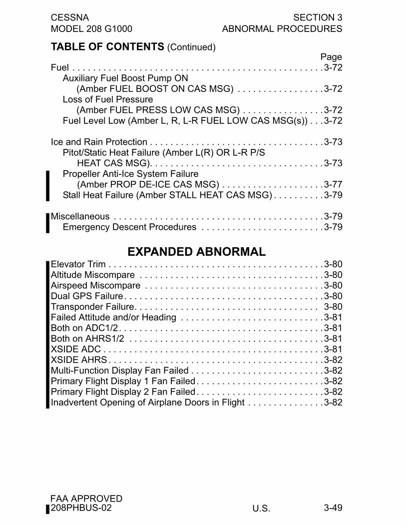
CESSNA SECTION 3MODEL 208 G1000 ABNORMAL PROCEDURES
U.S.FAA APPROVED
3-49
TABLE OF CONTENTS (Continued)Page
Fuel . . . . . . . . . . . . . . . . . . . . . . . . . . . . . . . . . . . . . . . . . . . . . . . . .3-72Auxiliary Fuel Boost Pump ON
(Amber FUEL BOOST ON CAS MSG) . . . . . . . . . . . . . . . . .3-72Loss of Fuel Pressure
(Amber FUEL PRESS LOW CAS MSG) . . . . . . . . . . . . . . . .3-72Fuel Level Low (Amber L, R, L-R FUEL LOW CAS MSG(s)) . . .3-72
Ice and Rain Protection . . . . . . . . . . . . . . . . . . . . . . . . . . . . . . . . . .3-73Pitot/Static Heat Failure (Amber L(R) OR L-R P/S
HEAT CAS MSG). . . . . . . . . . . . . . . . . . . . . . . . . . . . . . . . . .3-73Propeller Anti-Ice System Failure
(Amber PROP DE-ICE CAS MSG) . . . . . . . . . . . . . . . . . . . .3-77Stall Heat Failure (Amber STALL HEAT CAS MSG) . . . . . . . . . .3-79
Miscellaneous . . . . . . . . . . . . . . . . . . . . . . . . . . . . . . . . . . . . . . . . .3-79Emergency Descent Procedures . . . . . . . . . . . . . . . . . . . . . . . .3-79
EXPANDED ABNORMALElevator Trim . . . . . . . . . . . . . . . . . . . . . . . . . . . . . . . . . . . . . . . . . .3-80Altitude Miscompare . . . . . . . . . . . . . . . . . . . . . . . . . . . . . . . . . . . .3-80Airspeed Miscompare . . . . . . . . . . . . . . . . . . . . . . . . . . . . . . . . . . .3-80Dual GPS Failure. . . . . . . . . . . . . . . . . . . . . . . . . . . . . . . . . . . . . . .3-80Transponder Failure. . . . . . . . . . . . . . . . . . . . . . . . . . . . . . . . . . . . 3-80Failed Attitude and/or Heading . . . . . . . . . . . . . . . . . . . . . . . . . . . .3-81Both on ADC1/2. . . . . . . . . . . . . . . . . . . . . . . . . . . . . . . . . . . . . . . .3-81Both on AHRS1/2 . . . . . . . . . . . . . . . . . . . . . . . . . . . . . . . . . . . . . .3-81XSIDE ADC . . . . . . . . . . . . . . . . . . . . . . . . . . . . . . . . . . . . . . . . . . .3-81XSIDE AHRS . . . . . . . . . . . . . . . . . . . . . . . . . . . . . . . . . . . . . . . . . .3-82Multi-Function Display Fan Failed . . . . . . . . . . . . . . . . . . . . . . . . . .3-82Primary Flight Display 1 Fan Failed. . . . . . . . . . . . . . . . . . . . . . . . .3-82Primary Flight Display 2 Fan Failed. . . . . . . . . . . . . . . . . . . . . . . . .3-82Inadvertent Opening of Airplane Doors in Flight . . . . . . . . . . . . . . .3-82
208PHBUS-02
U.S.
SECTION 3 CESSNAABNORMAL PROCEDURES MODEL 208 G1000
FAA APPROVED3-50
This Page Intentionally Left Blank
208BPHBUS-02
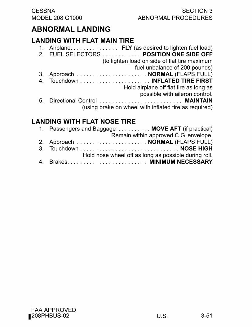
CESSNA SECTION 3MODEL 208 G1000 ABNORMAL PROCEDURES
U.S.FAA APPROVED
3-51
ABNORMAL LANDING
LANDING WITH FLAT MAIN TIRE1. Airplane. . . . . . . . . . . . . . . FLY (as desired to lighten fuel load)2. FUEL SELECTORS . . . . . . . . . . . . POSITION ONE SIDE OFF
(to lighten load on side of flat tire maximumfuel unbalance of 200 pounds)
3. Approach . . . . . . . . . . . . . . . . . . . . . . NORMAL (FLAPS FULL)4. Touchdown . . . . . . . . . . . . . . . . . . . . . . INFLATED TIRE FIRST
Hold airplane off flat tire as long aspossible with aileron control.
5. Directional Control . . . . . . . . . . . . . . . . . . . . . . . . . . MAINTAIN(using brake on wheel with inflated tire as required)
LANDING WITH FLAT NOSE TIRE1. Passengers and Baggage . . . . . . . . . . MOVE AFT (if practical)
Remain within approved C.G. envelope.2. Approach . . . . . . . . . . . . . . . . . . . . . . NORMAL (FLAPS FULL)3. Touchdown . . . . . . . . . . . . . . . . . . . . . . . . . . . . . . . NOSE HIGH
Hold nose wheel off as long as possible during roll.4. Brakes. . . . . . . . . . . . . . . . . . . . . . . . . MINIMUM NECESSARY
208PHBUS-02
U.S.
SECTION 3 CESSNAABNORMAL PROCEDURES MODEL 208 G1000
FAA APPROVED3-52
AVIONICS/AUTOPILOT
AILERON MISTRIM (AIL OR AIL INDICATION PFD)1. Control Wheel . . . . . . . . . . . . . . . . . . . . . . . . . . . GRIP FIRMLY2. AP/TRIM DISC Button. . . . . . . . . . . . . . . . . . . . . . . . . . PRESS
(high aileron control forces possible)
NOTE
The YAW DAMPER does not need to be disconnected forthis procedure. Therefore it is permissible to use the LEFThalf of either Manual Electric Pitch Trim Switch or 1 press ofthe AP button on the Autopilot Mode Control panel todisconnect the autopilot.
3. AILERON TRIM. . . . . . . . . . . . . . . . . . . . . . . . . . . . . . . RETRIM4. Autopilot . . . . . . . . . . . . . . . . . . . . . . . . . ENGAGE (as desired)
ELEVATOR MISTRIM (ELE OR ELE INDICATION PFD)1. Control Wheel . . . . . . . . . . . . . . . . . . . . . . . . . . . GRIP FIRMLY2. AP/TRIM DISC Button. . . . . . . . . . . . . . . . . . . . . . . . . . PRESS
(high elevator control forces possible)
NOTE
The yaw damper does not need to be disconnected for thisprocedure. Therefore it is permissible to use the LEFT halfof either Manual Electric Pitch Trim Switch or one press ofthe AP button on the Autopilot Mode Control panel todisconnect the autopilot.
3. Elevator Trim Switch . . . . . . . . . . . . . . . . . . . . . AS REQUIRED4. Autopilot . . . . . . . . . . . . . . . . . . . . . . . . . ENGAGE (as desired)
208PHBUS-02
CESSNA SECTION 3MODEL 208 G1000 ABNORMAL PROCEDURES
U.S.FAA APPROVED
3-53
RUDDER MISTRIM (RUD OR RUD INDICATION PFD)1. Rudder Pedals . . . . . . . . . . . . . . . . . . . . . . . . . . HOLD FIRMLY2. AP/TRIM DISC Button . . . . . . . . . . . . . . . . . . . . . . . . . . PRESS
(high rudder control forces possible)3. RUDDER TRIM. . . . . . . . . . . . . . . . . . . . . . . . . AS REQUIRED4. Autopilot and Yaw Damper . . . . . . . . . . . ENGAGE (as desired)
ALTITUDE MISCOMPARE (Amber ALT MISCOMPINDICATION PFD)
1. Altimeter Settings . . . . . . . . . . . . . . . . . . . . . . . . . . . . . VERIFY(both pilot and copilot have the correct altimeter setting)
IF ANNUNCIATION DOES NOT CLEAR2. Pilot and Copilot Altitude. . . . . . . . . . . . . . . . . . . . . . COMPARE
(with Standby Altimeter)
WARNING
The Standby Altimeter uses the same staticsources as the pilot’s side air data computer(ADC1). Do not use Standby Altimeter as solesource in determining correct altitude.
IF COPILOT PFD AND STANDBY ALTIMETER AGREE (PILOT PFDDIFFERS)
3. SENSOR Softkey (pilot PFD) . . . . . . . . . . . . . . . . . . . . . PRESS4. ADC2 Softkey . . . . . . . . . . . . . . . . . . . . . . . . . . . . . . . . . PRESS5. PFD ADI Displays . . . . . . . . . . . . . . . . . . . . . . . . . . . CONFIRM
(“BOTH ON ADC2” is displayed on both PFDs)
IF PILOT PFD AND STANDBY ALTIMETER AGREE (COPILOT PFDDIFFERS)
6. Autopilot . . . . . . . . . . . . . . . . DISENGAGE (altitude hold mode)7. ALT STATIC . . . . . . . . . . . . . . . . . . . . . . . . . . . PULL FULL ON
NOTE
The alternate static source is connected to the left PFD andstandby instruments only. Refer to Section 5, Performancefor airspeed and altimeter corrections.
(Continued Next Page)
208PHBUS-01
U.S.
SECTION 3 CESSNAABNORMAL PROCEDURES MODEL 208 G1000
FAA APPROVED3-54
ALTITUDE MISCOMPARE (Amber ALT MISCOMPINDICATION PFD) (Continued)
IF PILOT PFD AND STANDBY ALTIMETER AGREE (COPILOT PFDSTILL DIFFERS)
6. Compare indicated altitude to GPS altitude on MFD AUX-GPSSTATUS page to aid in determining which primary system ismost accurate.
NOTE
• When comparing indicated altitude to GPS altitude,deviations from standard temperature or pressure cancause indicated altitude to deviate from GPS altitude.These errors are largest at high altitude and can amountto over 2,500 feet under some conditions. However,below 10,000 feet with the correct local altimeter settingset, GPS altitude will usually be within 600 feet or betterof the correct indicated altitude. Use the followingguidelines to help estimate correct altitude for non-standard conditions:
• Temperatures WARMER than standard can cause GPSaltitude to read HIGHER than indicated altitude.
• Pressures LOWER than standard can cause GPSaltitude to read HIGHER than indicated altitude.
IF ABLE TO IDENTIFY ACCURATE ALTITUDE SOURCE5. Use SENSOR REVERSION to select most accurate ADC on
both PFDs.6. Land as soon as practical.
IF UNABLE TO IDENTIFY ACCURATE ALTITUDE SOURCE5. Land as soon as practical. Consider diversion to visual
conditions.6. Maintain altitudes based on LOWEST indicated altitude.7. ATC . . . . . . . . . . . ADVISE (of inability to verify correct altitude)8. If unable to descend into visual conditions, plan ILS approach
with course intercept well outside the Final Approach Fix (FAF).9. Once glideslope is captured, determine most accurate altitude
source when crossing FAF.
(Continued Next Page)
208PHBUS-01
CESSNA SECTION 3MODEL 208 G1000 ABNORMAL PROCEDURES
U.S.FAA APPROVED
3-55
ALTITUDE MISCOMPARE (Amber ALT MISCOMPINDICATION PFD) (Continued)
10. Reference ILS Decision Height to most accurate altimeter basedon FAF crossing.
WARNING
TAWS alerts are based on GPS altitude and positioninformation and are independent of ADC data. If aTAWS alert is received, it should be consideredvalid and appropriate terrain avoidance actionshould be taken.
AIRSPEED MISCOMPARE (Amber IAS MISCOMPINDICATION PFD)
1. Pilot and Copilot Airspeed . . . . . . . . . . . . . . . . . . . . COMPARE(with Standby Airspeed Indicator)
WARNING
The Standby Airspeed Indicator uses the samePitot-Static sources as the pilot’s side air datacomputer (ADC1). Do not use Standby AirspeedIndicator as sole source in determining correctairspeed.
(Continued Next Page)
208PHBUS-01
U.S.
SECTION 3 CESSNAABNORMAL PROCEDURES MODEL 208 G1000
FAA APPROVED3-56
AIRSPEED MISCOMPARE (Amber IAS MISCOMPINDICATION PFD) (Continued)
IF STANDBY AIRSPEED AND COPILOT PFD AGREE (PILOT PFDDIFFERS)
2. SENSOR Softkey (pilot PFD) . . . . . . . . . . . . . . . . . . . . PRESS3. ADC2 Softkey . . . . . . . . . . . . . . . . . . . . . . . . . . . . . . . . PRESS4. PFD ADI Displays . . . . . . . . . . . . . . . . . . . . . . . . . . . CONFIRM
(“BOTH ON ADC2” is displayed on both PFDs)
IF PILOT PFD AND STANDBY AIRSPEED AGREE (COPILOT PFDDIFFERS)
2. Pilot and Copilot ALTITUDE . . . . . . . . . . . . . . . . . . . . . . . NOTE
IF ALTITUDES AGREE3. Airspeed . . . . . . . . . 120 KIAS MINIMUM (on slowest indicator)4. Monitor all three airspeed indicators during changes in power
setting or altitude to determine which indicators are inaccurate.Indications of inaccurate airspeed include:a. No change in indicated airspeed when power changed and
altitude maintained.b. Indicated airspeed increases when climbing or decreases
when descending.5. Use SENSOR REVERSION to select most accurate ADC on the
affected PFD.6. Airspeed . . . . . . . . . . . . . . . . . . . RESUME NORMAL SPEEDS
IF ALTITUDES DO NOT AGREE3. Refer to Abnormal Procedures, ALT MISCOMP procedure to
determine most accurate ADC.
208PHBUS-01
CESSNA SECTION 3MODEL 208 G1000 ABNORMAL PROCEDURES
U.S.FAA APPROVED
3-57
PITCH/ROLL/HEADING MISCOMPARE (Amber PIT/ROLL/HDG MISCOMP INDICATION PFD)This message is displayed when the G1000 detects a differencebetween the pilot’s and copilot’s attitude or heading information(displayed in the upper right of the PFD). Refer to GARMIN G1000Cockpit Reference Guide for additional information.
PITCH OR ROLL MISCOMP INDICATION1. Refer to STANDBY ATTITUDE indicator to determine which
AHRS is providing the most accurate data.2. Use SENSOR REVERSION to select the most accurate AHRS
on the affected PFD.
HEADING MISCOMP1. Refer to Magnetic Compass to determine which AHRS is
providing the most accurate heading information.2. Use SENSOR REVERSION to select the most accurate AHRS
on the affected PFD.
NOTE
The magnetic compass is influenced by air conditioning. Itmust be turned OFF prior to referencing magnetic compassheading then may be reselected ON.
208PHBUS-01
U.S.
SECTION 3 CESSNAABNORMAL PROCEDURES MODEL 208 G1000
FAA APPROVED3-58
DISPLAY UNIT FAILUREThis is indicated by a complete loss of image on a display. If onlyindividual elements of the display are failed, refer to appropriateprocedures for the individual failures.
IF PILOT’S PFD1. DISPLAY BACKUP Button . . . . . . . . . . . . . PRESS (if required)
Flight and EICAS information will be displayed on the MFD. EISinformation will not be displayed on copilot’s PFD.
NOTE
The PFD CDI SYNC and BARO SYNC settings must be ONto allow the copilot’s PFD controls to affect settings on theMFD. These settings are accessible using the PFD MENUbutton.
2. Flight Director . . . . . . . . . . . . . . . . . . . . . . . . . . . . . TRANSFER(Press XFR button to operating PFD)
3. FD/AUTOPILOT Modes . . . . . . RESELECT and REENGAGE(as required)
4. Transponder . . . . . . . . . . . SWITCH (to operating transponder)5. COM and NAV Radios. . . . . . . . . . . . . . . . . . . . . . . . . SWITCH
(to operating Com and Nav radios)6. PFD Controls. . . . . . . . . . . . . . . . . . . . . USE OPERATING PFD
(for required data entry (Com, Nav, Baro setting, etc.))
IF MFD1. DISPLAY BACKUP Button . . . . . . . . . . . . . . . . . . . . . . PRESS
(EIS information will be displayed only on pilot’s PFD)
IF COPILOT’S PFDNo action is necessary. Normal operation on pilot’s PFD and MFD willnot be affected by loss of copilot’s PFD.
208PHBUS-02
CESSNA SECTION 3MODEL 208 G1000 ABNORMAL PROCEDURES
U.S.FAA APPROVED
3-59
DUAL GPS FAILURE (Amber “DR” OR “LOI” ON HSIINDICATION PFD)
IF ALTERNATE NAVIGATION SOURCES (ILS, LOC, VOR, DME,ADF) ARE AVAILABLE
1. Navigation. . . . . . . . . . . . . . . . . . USE ALTERNATE SOURCES
IF NO ALTERNATE NAVIGATION SOURCES ARE AVAILABLEDead reckoning (DR) mode active when the airplane is greater than 30nautical miles from the destination airport.
1. Navigation. . . . . . . . . . . . . . . . . . . . . . . . . . . . . . . . . . . . . . USE(the airplane symbol and magenta course
line on the map display)
WARNING
• All information normally derived from GPS turnsamber. All of this information will become moreinaccurate over time.
• TAWS is inoperative.
NOTE
• DR mode uses heading, airspeed, and the last knownGPS position to estimate the airplane’s current position.
• All maps with an airplane symbol show a ghostedairplane and a “DR” label.
(Continued Next Page)
208PHBUS-01
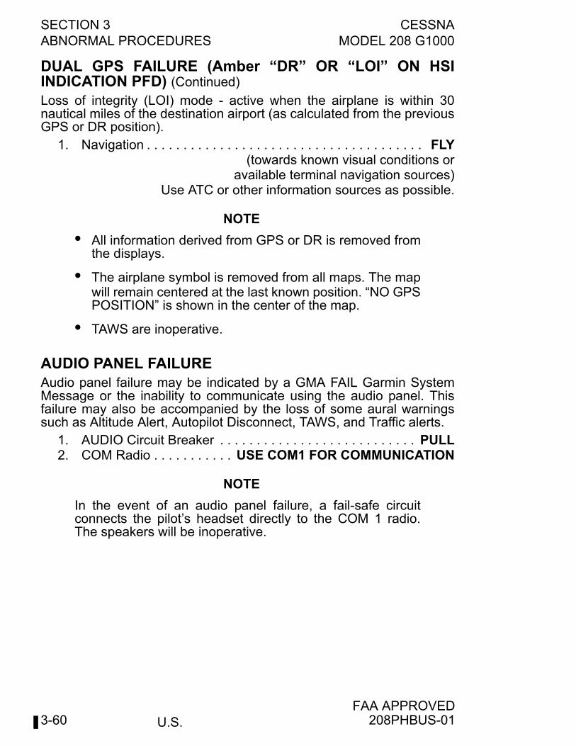
U.S.
SECTION 3 CESSNAABNORMAL PROCEDURES MODEL 208 G1000
FAA APPROVED3-60
DUAL GPS FAILURE (Amber “DR” OR “LOI” ON HSIINDICATION PFD) (Continued)
Loss of integrity (LOI) mode - active when the airplane is within 30nautical miles of the destination airport (as calculated from the previousGPS or DR position).
1. Navigation . . . . . . . . . . . . . . . . . . . . . . . . . . . . . . . . . . . . . . FLY(towards known visual conditions or
available terminal navigation sources)Use ATC or other information sources as possible.
NOTE
• All information derived from GPS or DR is removed fromthe displays.
• The airplane symbol is removed from all maps. The mapwill remain centered at the last known position. “NO GPSPOSITION” is shown in the center of the map.
• TAWS are inoperative.
AUDIO PANEL FAILUREAudio panel failure may be indicated by a GMA FAIL Garmin SystemMessage or the inability to communicate using the audio panel. Thisfailure may also be accompanied by the loss of some aural warningssuch as Altitude Alert, Autopilot Disconnect, TAWS, and Traffic alerts.
1. AUDIO Circuit Breaker . . . . . . . . . . . . . . . . . . . . . . . . . . . PULL2. COM Radio . . . . . . . . . . . USE COM1 FOR COMMUNICATION
NOTE
In the event of an audio panel failure, a fail-safe circuitconnects the pilot’s headset directly to the COM 1 radio.The speakers will be inoperative.
208PHBUS-01
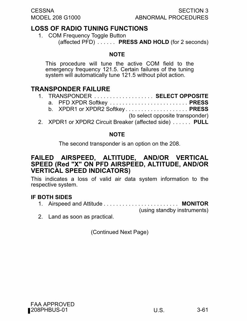
CESSNA SECTION 3MODEL 208 G1000 ABNORMAL PROCEDURES
U.S.FAA APPROVED
3-61
LOSS OF RADIO TUNING FUNCTIONS1. COM Frequency Toggle Button
(affected PFD) . . . . . . PRESS AND HOLD (for 2 seconds)
NOTE
This procedure will tune the active COM field to theemergency frequency 121.5. Certain failures of the tuningsystem will automatically tune 121.5 without pilot action.
TRANSPONDER FAILURE1. TRANSPONDER . . . . . . . . . . . . . . . . . . . SELECT OPPOSITE
a. PFD XPDR Softkey . . . . . . . . . . . . . . . . . . . . . . . . . PRESSb. XPDR1 or XPDR2 Softkey . . . . . . . . . . . . . . . . . . . . PRESS
(to select opposite transponder)2. XPDR1 or XPDR2 Circuit Breaker (affected side) . . . . . . PULL
NOTE
The second transponder is an option on the 208.
FAILED AIRSPEED, ALTITUDE, AND/OR VERTICALSPEED (Red "X" ON PFD AIRSPEED, ALTITUDE, AND/ORVERTICAL SPEED INDICATORS)This indicates a loss of valid air data system information to therespective system.
IF BOTH SIDES1. Airspeed and Attitude . . . . . . . . . . . . . . . . . . . . . . . . MONITOR
(using standby instruments)2. Land as soon as practical.
(Continued Next Page)
208PHBUS-01
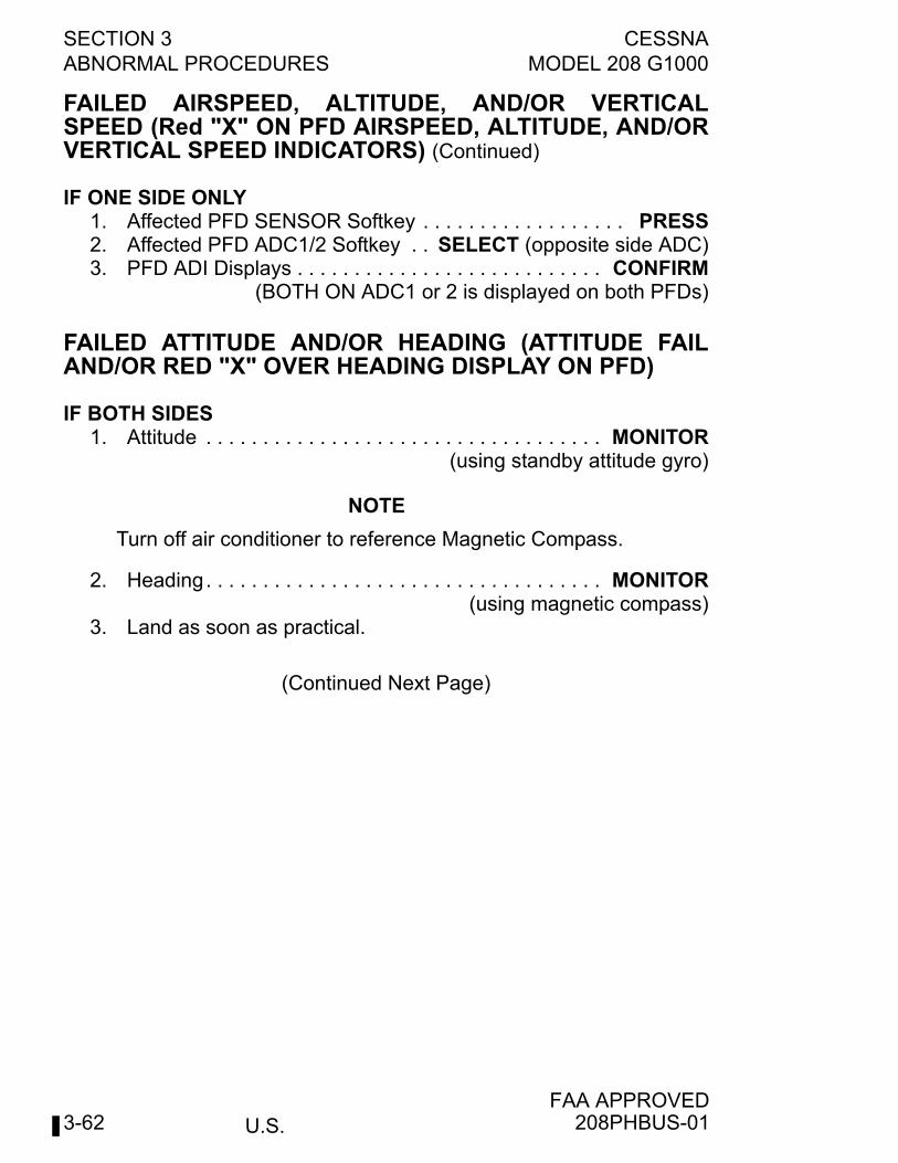
U.S.
SECTION 3 CESSNAABNORMAL PROCEDURES MODEL 208 G1000
FAA APPROVED3-62
FAILED AIRSPEED, ALTITUDE, AND/OR VERTICALSPEED (Red "X" ON PFD AIRSPEED, ALTITUDE, AND/ORVERTICAL SPEED INDICATORS) (Continued)
IF ONE SIDE ONLY1. Affected PFD SENSOR Softkey . . . . . . . . . . . . . . . . . . PRESS2. Affected PFD ADC1/2 Softkey . . SELECT (opposite side ADC)3. PFD ADI Displays . . . . . . . . . . . . . . . . . . . . . . . . . . . CONFIRM
(BOTH ON ADC1 or 2 is displayed on both PFDs)
FAILED ATTITUDE AND/OR HEADING (ATTITUDE FAILAND/OR RED "X" OVER HEADING DISPLAY ON PFD)
IF BOTH SIDES1. Attitude . . . . . . . . . . . . . . . . . . . . . . . . . . . . . . . . . . . MONITOR
(using standby attitude gyro)
NOTE
Turn off air conditioner to reference Magnetic Compass.
2. Heading. . . . . . . . . . . . . . . . . . . . . . . . . . . . . . . . . . . MONITOR(using magnetic compass)
3. Land as soon as practical.
(Continued Next Page)
208PHBUS-01
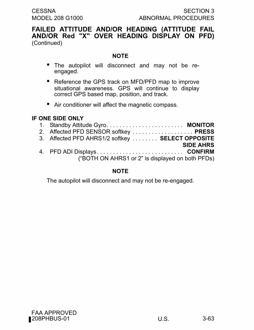
CESSNA SECTION 3MODEL 208 G1000 ABNORMAL PROCEDURES
U.S.FAA APPROVED
3-63
FAILED ATTITUDE AND/OR HEADING (ATTITUDE FAILAND/OR Red "X" OVER HEADING DISPLAY ON PFD)(Continued)
NOTE
• The autopilot will disconnect and may not be re-engaged.
• Reference the GPS track on MFD/PFD map to improvesituational awareness. GPS will continue to displaycorrect GPS based map, position, and track.
• Air conditioner will affect the magnetic compass.
IF ONE SIDE ONLY1. Standby Attitude Gyro. . . . . . . . . . . . . . . . . . . . . . . . MONITOR2. Affected PFD SENSOR softkey . . . . . . . . . . . . . . . . . . . PRESS3. Affected PFD AHRS1/2 softkey . . . . . . . . SELECT OPPOSITE
SIDE AHRS4. PFD ADI Displays . . . . . . . . . . . . . . . . . . . . . . . . . . . CONFIRM
(“BOTH ON AHRS1 or 2” is displayed on both PFDs)
NOTE
The autopilot will disconnect and may not be re-engaged.
208PHBUS-01
U.S.
SECTION 3 CESSNAABNORMAL PROCEDURES MODEL 208 G1000
FAA APPROVED3-64
LOSS OF NAVIGATION DATA (LATERAL DEVIATION BARNOT PRESENT AND/OR GLIDESLOPE INDEX CLEARS)This indicates a loss of data from the selected NAV source. Refer toGARMIN G1000 Cockpit Reference Guide for additional information.
1. Opposite NAV Source . . . . . . . . . . . . . . . . . . . . . . . . . SELECT2. PFD HSI Displays . . . . . . . . . . . . . . . . . CONFIRM OPPOSITE
(“LOC1/LOC2” or “VOR1/VOR2” is displayed on both PFDs)
INACCURATE OVERSPEED WARNINGIndicated by overspeed warning tone sounding when airspeed is belowthe limit speed.
1. AIRSPEED . . . . . . . . . . . . . . . . . . . . . . . . . . . CROSS CHECK(with opposite PFD)
2. AIRSPEED . . . . . . . . . . . . . . . . . . . . . . REDUCE (as required)
IF BOTH AIRSPEEDS INDICATE BELOW VMO AND TONE STILLSOUNDS
3. AIRSPEED Circuit Breaker . . . . . . . . . . . . . . . . . . . . . . . . PULL(fifth row, eighth breaker from aft)
4. Land as soon as practical.
IF AIRSPEEDS DO NOT AGREE3. Refer to IAS MISCOMP procedure.
208PHBUS-02
CESSNA SECTION 3MODEL 208 G1000 ABNORMAL PROCEDURES
U.S.FAA APPROVED
3-65
INACCURATE FLIGHT DIRECTOR DISPLAYIndicated by one or both flight directors commanding attitude contraryto intended flight path.
1. AP/TRIM DISC Button . . . . . . . . . . . . . . . . . . . . . . . . . . PRESS2. Attitude . . . . . . . . . . . . . . . . . . . . CROSS CHECK BOTH PFDs
(with the Standby Attitude Indicator)3. Flight Director Modes . . . . . . . . . . . . . RESELECT (as desired)
NOTE
If continued use of the flight director is desired, it isrecommended that only basic modes (i.e., ROL and PIT) beselected initially. If this proves satisfactory, HDG and ALTmay then be selected. Make sure navigation systems areset up correctly prior to attempting to engage NAV mode.
4. Autopilot . . . . . . . . . . . . . . . . . . . . . . . ENGAGE AS DESIRED(if flight director commands are appropriate)
BOTH PFDs DISPLAYING SAME ADC (Amber BOTH ONADC1/2 CAS MSG)
1. PFD SENSOR softkey . . . . . . . . . . . . . . . . . . . PRESS on PFD(displaying data from opposite side ADC)
2. PFD ADC1/2 softkey. . . . . . . . . . . . . . SELECT ON-SIDE ADC(ADC1 for Pilot PFD, ADC2 for copilot PFD)
3. PFD Displays . . . . . . . . . . . . . . . . . . . . . . . . . . . . . . CONFIRM(“BOTH ON ADC1 or 2” message clears on both PFDs and no
Red “X” on PFD 1/2 Airspeed indicator)
208PHBUS-02
U.S.
SECTION 3 CESSNAABNORMAL PROCEDURES MODEL 208 G1000
FAA APPROVED3-66
BOTH PFDs DISPLAYING SAME AHRS (Amber BOTH ONAHRS1/2 CAS MSG)
1. PFD SENSOR softkey. . . . . . . . . . . . . . . . . . . . PRESS on PFD(displaying data from opposite side AHRS)
2. PFD AHRS1/2 softkey. . . . . . . . . . . . SELECT ON-SIDE AHRS(AHRS1 for Pilot PFD, AHRS2 for copilot PFD)
3. PFD Displays. . . . . . . . . . . . . . . . . . . . . . . . . . . . . . . CONFIRM(“BOTH ON AHRS1 or 2” message clears on both PFDs and no
Red “X” on PFD 1/2 Attitude)
BOTH PFDs DISPLAYING SAME GPS (Amber BOTH ONGPS1/2 CAS MSG)
1. GPS Status . . . . . . . . . . . . . . . . . . . . . . . . . . . . . . . . . . CHECKa. Select MFD . . . . . . . . . . . . . . . . AUX-GPS STATUS PAGEb. Select GPS1 then GPS2 softkeys and verify sufficient
satellite reception.
CROSS-SIDE PITOT/STATIC INFORMATION (Amber XSIDEADC CAS MSG)
1. Either PFD SENSOR softkey . . . . . . . . . . . . . . . . . . . . PRESS2. PFD ADC1/2 softkey . . . . . . . . . . . . . . SELECT ON-SIDE ADC
(ADC1 for Pilot PFD, ADC2 for copilot PFD)3. PFD Displays. . . . . . . . . . . . . . . . . . . . . . . . . . . . . . . CONFIRM
(“BOTH ON ADC1 or 2” message displays on both PFDs)4. Repeat procedure on opposite PFD.5. PFD Displays. . . . . . . . . . . . . . . . . . . . . . . . . . . . . . . CONFIRM
(“BOTH ON ADC1 or 2” message clears on both PFDs)
CROSS-SIDE ATTITUDE AND HEADING INFORMATION(Amber XSIDE AHRS CAS MSG)
1. Either PFD SENSOR softkey . . . . . . . . . . . . . . . . . . . . PRESS2. PFD AHRS1/2 softkey. . . . . . . . . . . . SELECT ON-SIDE AHRS
(AHRS1 for Pilot PFD, AHRS2 for copilot PFD)3. PFD Displays. . . . . . . . . . . . . . . . . . . . . . . . . . . . . . . CONFIRM
(“BOTH ON AHRS1 or 2” message displays on both PFDs)4. Repeat procedure on opposite PFD.5. PFD Displays. . . . . . . . . . . . . . . . . . . . . . . . . . . . . . . CONFIRM
(“BOTH ON AHRS1 or 2” message clears on both PFDs)
208PHBUS-02
CESSNA SECTION 3MODEL 208 G1000 ABNORMAL PROCEDURES
U.S.FAA APPROVED
3-67
MULTI-FUNCTION DISPLAY FAN FAILED (White MFD FANFAIL CAS MSG)
1. DECK SKIN FAN Circuit Breaker . . . . . . . . . . . . . . . CHECK IN
PRIMARY FLIGHT DISPLAY 1 FAN FAILED (White PFD1FAN FAIL CAS MSG)
1. DECK SKIN FAN Circuit Breaker . . . . . . . . . . . . . . . CHECK IN
PRIMARY FLIGHT DISPLAY 2 FAN FAILED (White PFD 2FAN FAIL CAS MSG)
1. DECK SKIN FAN Circuit Breaker . . . . . . . . . . . . . . . CHECK IN
DOORS
UPPER HALF OF CARGO DOOR OR UPPER HALF OFPASSENGER AIRSTAIR DOOR OPEN (Amber DOORUNLATCHED CAS MSG)
1. Airspeed . . . . . . . . . . . . . . . MAINTAIN LESS THAN 100 KIAS2. WING FLAPS . . . . . . . . . . . . . . . . . . . . . . . . . . . . . . . . . . FULL
Wing downwash with flaps extended will move the doors neartheir normally closed position.
3. If available or practical, have a second crew member go aft toclose and latch door.
4. SEAT BELT/NO SMOKE Light . . . . . . . . . . . . . . . . . . . . . . . ON5. If landing is required with door open:
a. Approach and Landing . . . . . . . . . . . . . . . . . . . . . NORMAL
208PHBUS-01
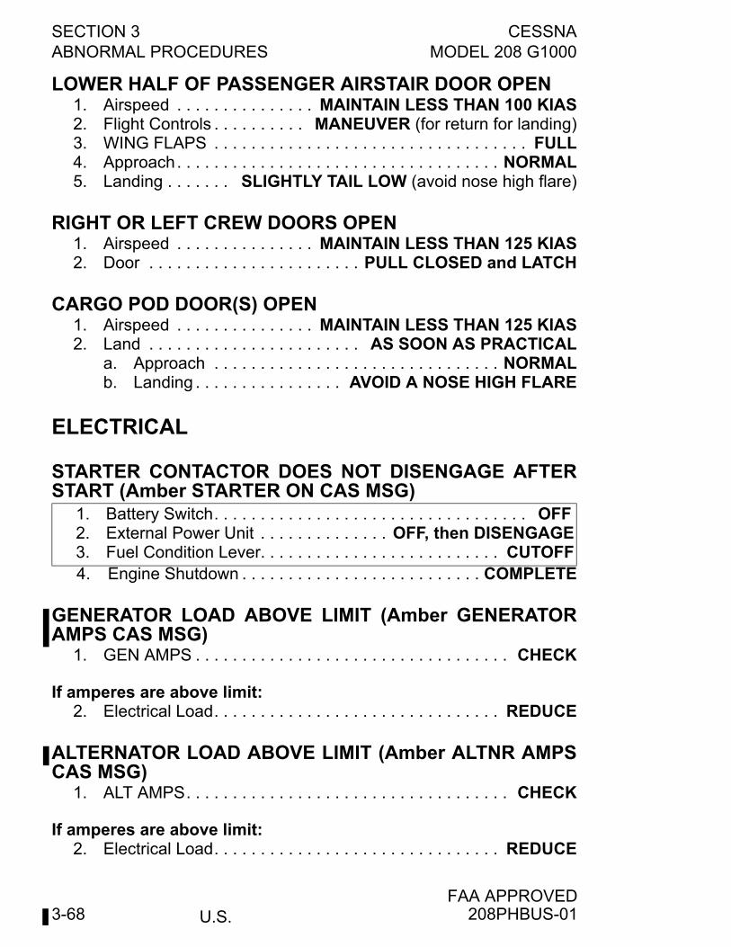
U.S.
SECTION 3 CESSNAABNORMAL PROCEDURES MODEL 208 G1000
FAA APPROVED3-68
LOWER HALF OF PASSENGER AIRSTAIR DOOR OPEN1. Airspeed . . . . . . . . . . . . . . . MAINTAIN LESS THAN 100 KIAS2. Flight Controls . . . . . . . . . . MANEUVER (for return for landing)3. WING FLAPS . . . . . . . . . . . . . . . . . . . . . . . . . . . . . . . . . . FULL4. Approach. . . . . . . . . . . . . . . . . . . . . . . . . . . . . . . . . . . NORMAL5. Landing . . . . . . . SLIGHTLY TAIL LOW (avoid nose high flare)
RIGHT OR LEFT CREW DOORS OPEN1. Airspeed . . . . . . . . . . . . . . . MAINTAIN LESS THAN 125 KIAS2. Door . . . . . . . . . . . . . . . . . . . . . . . PULL CLOSED and LATCH
CARGO POD DOOR(S) OPEN1. Airspeed . . . . . . . . . . . . . . . MAINTAIN LESS THAN 125 KIAS2. Land . . . . . . . . . . . . . . . . . . . . . . . AS SOON AS PRACTICAL
a. Approach . . . . . . . . . . . . . . . . . . . . . . . . . . . . . . . NORMALb. Landing . . . . . . . . . . . . . . . . AVOID A NOSE HIGH FLARE
ELECTRICAL
STARTER CONTACTOR DOES NOT DISENGAGE AFTERSTART (Amber STARTER ON CAS MSG)
4. Engine Shutdown . . . . . . . . . . . . . . . . . . . . . . . . . . COMPLETE
GENERATOR LOAD ABOVE LIMIT (Amber GENERATORAMPS CAS MSG)
1. GEN AMPS . . . . . . . . . . . . . . . . . . . . . . . . . . . . . . . . . . CHECK
If amperes are above limit:2. Electrical Load. . . . . . . . . . . . . . . . . . . . . . . . . . . . . . . REDUCE
ALTERNATOR LOAD ABOVE LIMIT (Amber ALTNR AMPSCAS MSG)
1. ALT AMPS. . . . . . . . . . . . . . . . . . . . . . . . . . . . . . . . . . . CHECK
If amperes are above limit:2. Electrical Load. . . . . . . . . . . . . . . . . . . . . . . . . . . . . . . REDUCE
1. Battery Switch. . . . . . . . . . . . . . . . . . . . . . . . . . . . . . . . . . OFF2. External Power Unit . . . . . . . . . . . . . . OFF, then DISENGAGE3. Fuel Condition Lever. . . . . . . . . . . . . . . . . . . . . . . . . . CUTOFF
208PHBUS-01
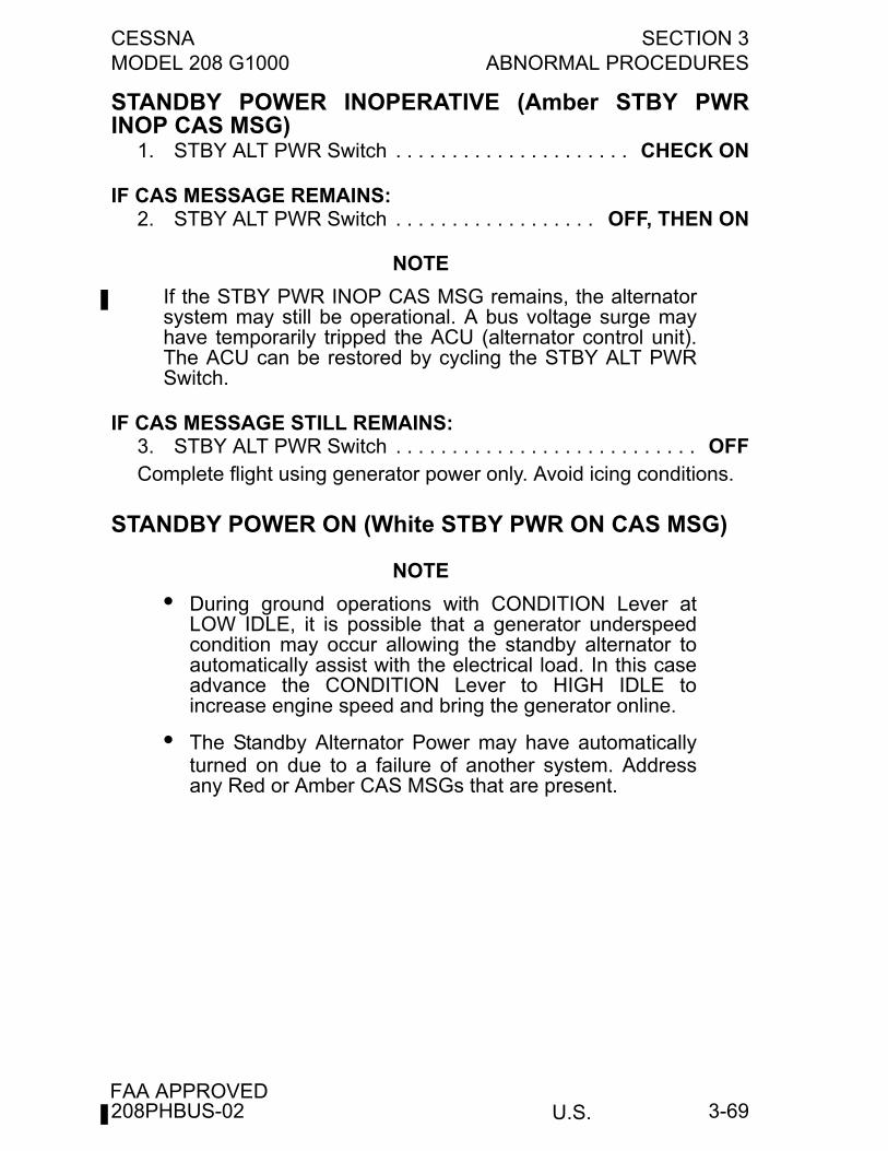
CESSNA SECTION 3MODEL 208 G1000 ABNORMAL PROCEDURES
U.S.FAA APPROVED
3-69
STANDBY POWER INOPERATIVE (Amber STBY PWRINOP CAS MSG)
1. STBY ALT PWR Switch . . . . . . . . . . . . . . . . . . . . . CHECK ON
IF CAS MESSAGE REMAINS:2. STBY ALT PWR Switch . . . . . . . . . . . . . . . . . . OFF, THEN ON
NOTE
If the STBY PWR INOP CAS MSG remains, the alternatorsystem may still be operational. A bus voltage surge mayhave temporarily tripped the ACU (alternator control unit).The ACU can be restored by cycling the STBY ALT PWRSwitch.
IF CAS MESSAGE STILL REMAINS:3. STBY ALT PWR Switch . . . . . . . . . . . . . . . . . . . . . . . . . . . OFFComplete flight using generator power only. Avoid icing conditions.
STANDBY POWER ON (White STBY PWR ON CAS MSG)
NOTE
• During ground operations with CONDITION Lever atLOW IDLE, it is possible that a generator underspeedcondition may occur allowing the standby alternator toautomatically assist with the electrical load. In this caseadvance the CONDITION Lever to HIGH IDLE toincrease engine speed and bring the generator online.
• The Standby Alternator Power may have automaticallyturned on due to a failure of another system. Addressany Red or Amber CAS MSGs that are present.
208PHBUS-02
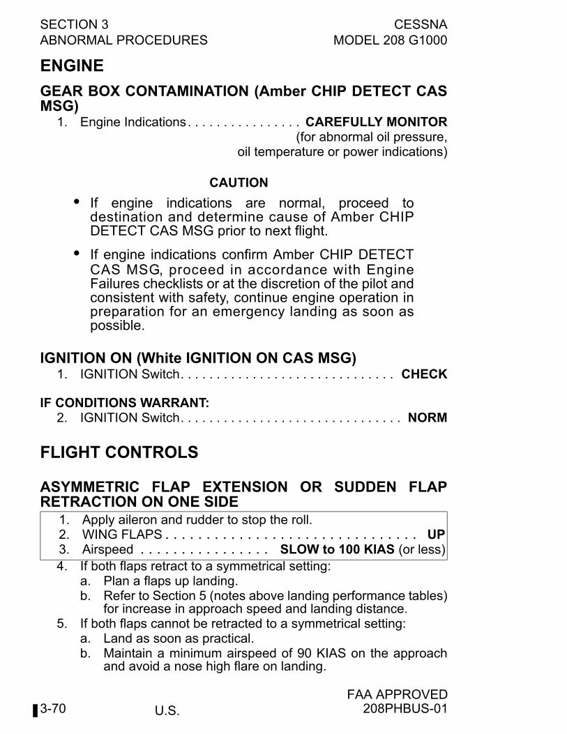
U.S.
SECTION 3 CESSNAABNORMAL PROCEDURES MODEL 208 G1000
FAA APPROVED3-70
ENGINE
GEAR BOX CONTAMINATION (Amber CHIP DETECT CASMSG)
1. Engine Indications. . . . . . . . . . . . . . . . CAREFULLY MONITOR(for abnormal oil pressure,
oil temperature or power indications)
CAUTION
• If engine indications are normal, proceed todestination and determine cause of Amber CHIPDETECT CAS MSG prior to next flight.
• If engine indications confirm Amber CHIP DETECTCAS MSG, proceed in accordance with EngineFailures checklists or at the discretion of the pilot andconsistent with safety, continue engine operation inpreparation for an emergency landing as soon aspossible.
IGNITION ON (White IGNITION ON CAS MSG)1. IGNITION Switch. . . . . . . . . . . . . . . . . . . . . . . . . . . . . . CHECK
IF CONDITIONS WARRANT:2. IGNITION Switch. . . . . . . . . . . . . . . . . . . . . . . . . . . . . . . NORM
FLIGHT CONTROLS
ASYMMETRIC FLAP EXTENSION OR SUDDEN FLAPRETRACTION ON ONE SIDE
4. If both flaps retract to a symmetrical setting:a. Plan a flaps up landing.b. Refer to Section 5 (notes above landing performance tables)
for increase in approach speed and landing distance.5. If both flaps cannot be retracted to a symmetrical setting:
a. Land as soon as practical.b. Maintain a minimum airspeed of 90 KIAS on the approach
and avoid a nose high flare on landing.
1. Apply aileron and rudder to stop the roll.2. WING FLAPS . . . . . . . . . . . . . . . . . . . . . . . . . . . . . . . UP3. Airspeed . . . . . . . . . . . . . . . . SLOW to 100 KIAS (or less)
208PHBUS-01
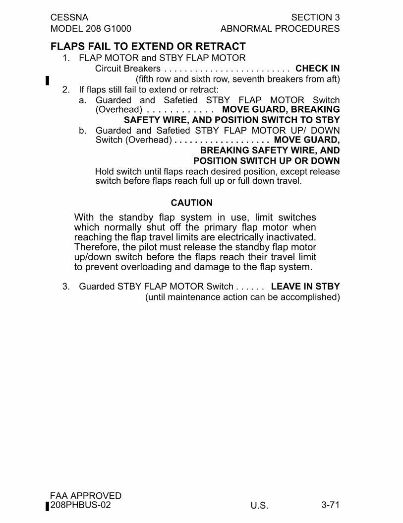
CESSNA SECTION 3MODEL 208 G1000 ABNORMAL PROCEDURES
U.S.FAA APPROVED
3-71
FLAPS FAIL TO EXTEND OR RETRACT1. FLAP MOTOR and STBY FLAP MOTOR
Circuit Breakers . . . . . . . . . . . . . . . . . . . . . . . . . CHECK IN(fifth row and sixth row, seventh breakers from aft)
2. If flaps still fail to extend or retract:a. Guarded and Safetied STBY FLAP MOTOR Switch
(Overhead) . . . . . . . . . . . . MOVE GUARD, BREAKINGSAFETY WIRE, AND POSITION SWITCH TO STBY
b. Guarded and Safetied STBY FLAP MOTOR UP/ DOWNSwitch (Overhead) . . . . . . . . . . . . . . . . . . . MOVE GUARD,
BREAKING SAFETY WIRE, ANDPOSITION SWITCH UP OR DOWN
Hold switch until flaps reach desired position, except releaseswitch before flaps reach full up or full down travel.
CAUTION
With the standby flap system in use, limit switcheswhich normally shut off the primary flap motor whenreaching the flap travel limits are electrically inactivated.Therefore, the pilot must release the standby flap motorup/down switch before the flaps reach their travel limitto prevent overloading and damage to the flap system.
3. Guarded STBY FLAP MOTOR Switch . . . . . . LEAVE IN STBY(until maintenance action can be accomplished)
208PHBUS-02
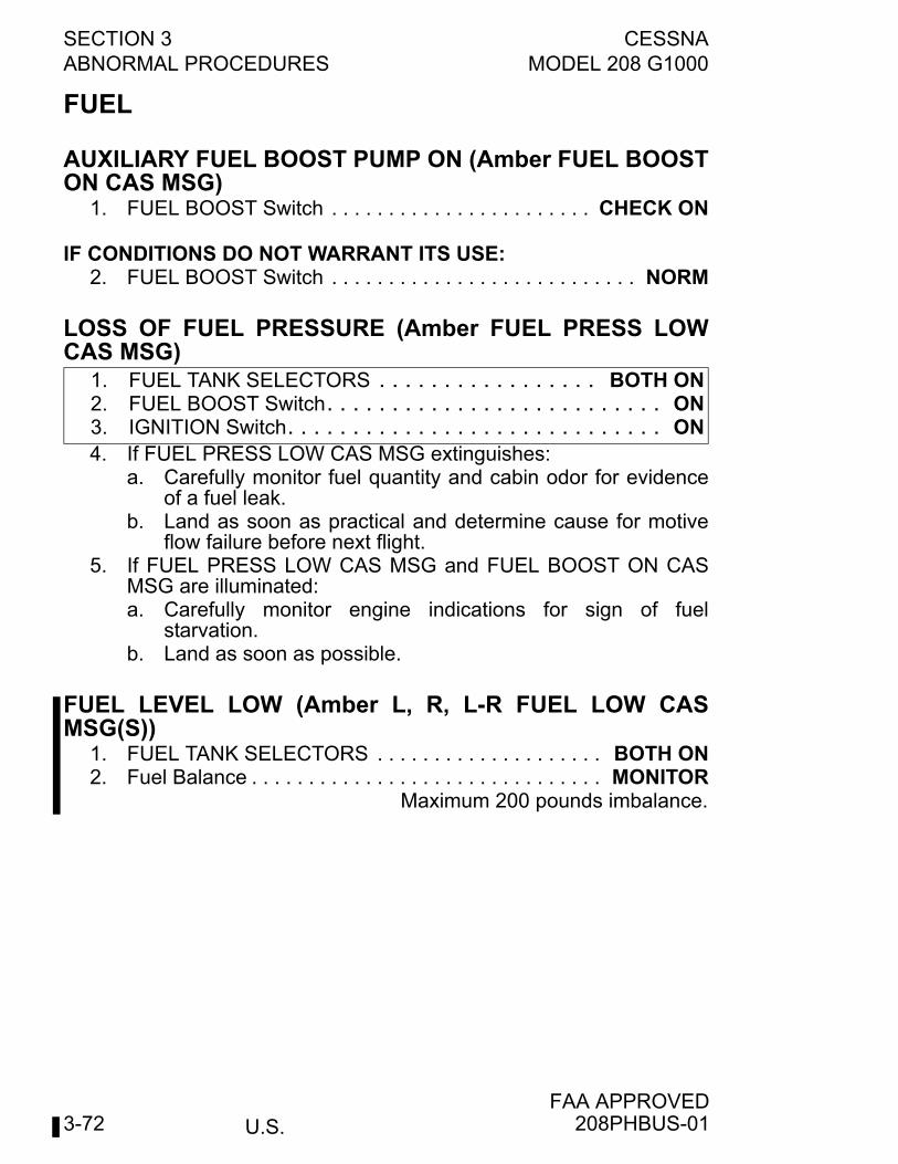
U.S.
SECTION 3 CESSNAABNORMAL PROCEDURES MODEL 208 G1000
FAA APPROVED3-72
FUEL
AUXILIARY FUEL BOOST PUMP ON (Amber FUEL BOOSTON CAS MSG)
1. FUEL BOOST Switch . . . . . . . . . . . . . . . . . . . . . . . CHECK ON
IF CONDITIONS DO NOT WARRANT ITS USE:2. FUEL BOOST Switch . . . . . . . . . . . . . . . . . . . . . . . . . . . NORM
LOSS OF FUEL PRESSURE (Amber FUEL PRESS LOWCAS MSG)
4. If FUEL PRESS LOW CAS MSG extinguishes:a. Carefully monitor fuel quantity and cabin odor for evidence
of a fuel leak.b. Land as soon as practical and determine cause for motive
flow failure before next flight.5. If FUEL PRESS LOW CAS MSG and FUEL BOOST ON CAS
MSG are illuminated:a. Carefully monitor engine indications for sign of fuel
starvation.b. Land as soon as possible.
FUEL LEVEL LOW (Amber L, R, L-R FUEL LOW CASMSG(S))
1. FUEL TANK SELECTORS . . . . . . . . . . . . . . . . . . . . BOTH ON2. Fuel Balance . . . . . . . . . . . . . . . . . . . . . . . . . . . . . . . MONITOR
Maximum 200 pounds imbalance.
1. FUEL TANK SELECTORS . . . . . . . . . . . . . . . . . BOTH ON2. FUEL BOOST Switch. . . . . . . . . . . . . . . . . . . . . . . . . . ON3. IGNITION Switch. . . . . . . . . . . . . . . . . . . . . . . . . . . . . ON
208PHBUS-01
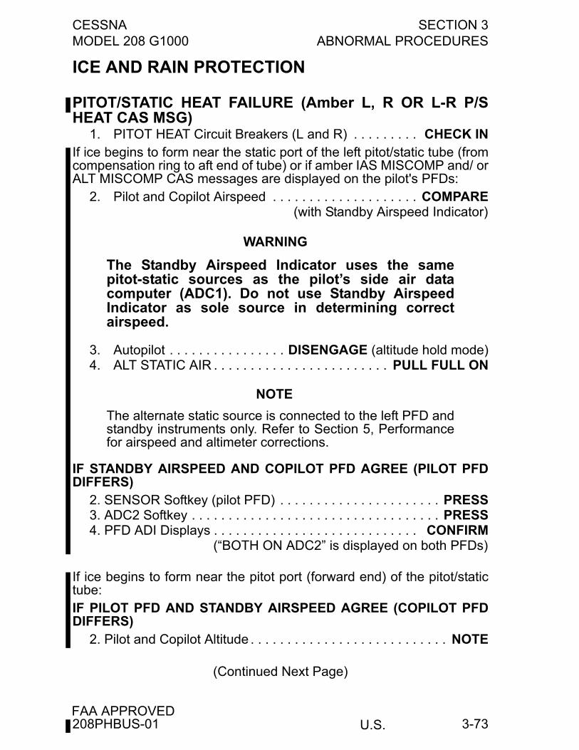
CESSNA SECTION 3MODEL 208 G1000 ABNORMAL PROCEDURES
U.S.FAA APPROVED
3-73
ICE AND RAIN PROTECTION
PITOT/STATIC HEAT FAILURE (Amber L, R OR L-R P/SHEAT CAS MSG)
1. PITOT HEAT Circuit Breakers (L and R) . . . . . . . . . CHECK INIf ice begins to form near the static port of the left pitot/static tube (fromcompensation ring to aft end of tube) or if amber IAS MISCOMP and/ orALT MISCOMP CAS messages are displayed on the pilot's PFDs:
2. Pilot and Copilot Airspeed . . . . . . . . . . . . . . . . . . . . COMPARE(with Standby Airspeed Indicator)
WARNING
The Standby Airspeed Indicator uses the samepitot-static sources as the pilot’s side air datacomputer (ADC1). Do not use Standby AirspeedIndicator as sole source in determining correctairspeed.
3. Autopilot . . . . . . . . . . . . . . . . DISENGAGE (altitude hold mode)4. ALT STATIC AIR . . . . . . . . . . . . . . . . . . . . . . . . PULL FULL ON
NOTE
The alternate static source is connected to the left PFD andstandby instruments only. Refer to Section 5, Performancefor airspeed and altimeter corrections.
IF STANDBY AIRSPEED AND COPILOT PFD AGREE (PILOT PFDDIFFERS)
2. SENSOR Softkey (pilot PFD) . . . . . . . . . . . . . . . . . . . . . . PRESS3. ADC2 Softkey . . . . . . . . . . . . . . . . . . . . . . . . . . . . . . . . . . PRESS4. PFD ADI Displays . . . . . . . . . . . . . . . . . . . . . . . . . . . . CONFIRM
(“BOTH ON ADC2” is displayed on both PFDs)
If ice begins to form near the pitot port (forward end) of the pitot/statictube:IF PILOT PFD AND STANDBY AIRSPEED AGREE (COPILOT PFDDIFFERS)
2. Pilot and Copilot Altitude . . . . . . . . . . . . . . . . . . . . . . . . . . . NOTE
(Continued Next Page)
208PHBUS-01
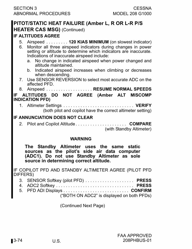
U.S.
SECTION 3 CESSNAABNORMAL PROCEDURES MODEL 208 G1000
FAA APPROVED3-74
PITOT/STATIC HEAT FAILURE (Amber L, R OR L-R P/S HEATER CAS MSG) (Continued)
IF ALTITUDES AGREE5. Airspeed . . . . . . . . . 120 KIAS MINIMUM (on slowest indicator)6. Monitor all three airspeed indicators during changes in power
setting or altitude to determine which indicators are inaccurate.Indications of inaccurate airspeed include:a. No change in indicated airspeed when power changed and
altitude maintained.b. Indicated airspeed increases when climbing or decreases
when descending.7. Use SENSOR REVERSION to select most accurate ADC on the
affected PFD.8. Airspeed . . . . . . . . . . . . . . . . . . . RESUME NORMAL SPEEDS
IF ALTITUDES DO NOT AGREE (Amber ALT MISCOMPINDICATION PFD)
1. Altimeter Settings . . . . . . . . . . . . . . . . . . . . . . . . . . . . . VERIFY(both pilot and copilot have the correct altimeter setting)
IF ANNUNCIATION DOES NOT CLEAR
2. Pilot and Copilot Altitude . . . . . . . . . . . . . . . . . . . . . COMPARE(with Standby Altimeter)
WARNING
The Standby Altimeter uses the same staticsources as the pilot’s side air data computer(ADC1). Do not use Standby Altimeter as solesource in determining correct altitude.
IF COPILOT PFD AND STANDBY ALTIMETER AGREE (PILOT PFDDIFFERS)
3. SENSOR Softkey (pilot PFD) . . . . . . . . . . . . . . . . . . . . PRESS4. ADC2 Softkey . . . . . . . . . . . . . . . . . . . . . . . . . . . . . . . . PRESS5. PFD ADI Displays . . . . . . . . . . . . . . . . . . . . . . . . . . . CONFIRM
(“BOTH ON ADC2” is displayed on both PFDs)
(Continued Next Page)
208PHBUS-01
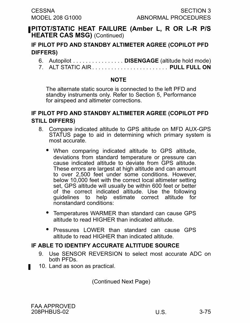
CESSNA SECTION 3MODEL 208 G1000 ABNORMAL PROCEDURES
U.S.FAA APPROVED
3-75
PITOT/STATIC HEAT FAILURE (Amber L, R OR L-R P/SHEATER CAS MSG) (Continued)
IF PILOT PFD AND STANDBY ALTIMETER AGREE (COPILOT PFD DIFFERS)
6. Autopilot . . . . . . . . . . . . . . . . DISENGAGE (altitude hold mode)7. ALT STATIC AIR . . . . . . . . . . . . . . . . . . . . . . . . PULL FULL ON
NOTE
The alternate static source is connected to the left PFD andstandby instruments only. Refer to Section 5, Performancefor airspeed and altimeter corrections.
IF PILOT PFD AND STANDBY ALTIMETER AGREE (COPILOT PFD STILL DIFFERS)
8. Compare indicated altitude to GPS altitude on MFD AUX-GPSSTATUS page to aid in determining which primary system ismost accurate.
• When comparing indicated altitude to GPS altitude,deviations from standard temperature or pressure cancause indicated altitude to deviate from GPS altitude.These errors are largest at high altitude and can amountto over 2,500 feet under some conditions. However,below 10,000 feet with the correct local altimeter settingset, GPS altitude will usually be within 600 feet or betterof the correct indicated altitude. Use the followingguidelines to help estimate correct altitude fornonstandard conditions:
• Temperatures WARMER than standard can cause GPSaltitude to read HIGHER than indicated altitude.
• Pressures LOWER than standard can cause GPSaltitude to read HIGHER than indicated altitude.
IF ABLE TO IDENTIFY ACCURATE ALTITUDE SOURCE
9. Use SENSOR REVERSION to select most accurate ADC onboth PFDs.
10. Land as soon as practical.
(Continued Next Page)
208PHBUS-02
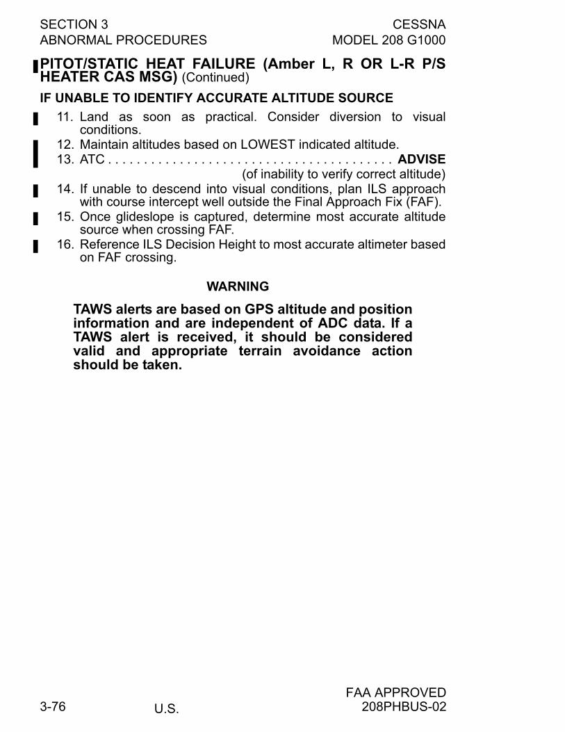
U.S.
SECTION 3 CESSNAABNORMAL PROCEDURES MODEL 208 G1000
FAA APPROVED3-76
PITOT/STATIC HEAT FAILURE (Amber L, R OR L-R P/SHEATER CAS MSG) (Continued)
IF UNABLE TO IDENTIFY ACCURATE ALTITUDE SOURCE
11. Land as soon as practical. Consider diversion to visualconditions.
12. Maintain altitudes based on LOWEST indicated altitude.13. ATC . . . . . . . . . . . . . . . . . . . . . . . . . . . . . . . . . . . . . . . . ADVISE
(of inability to verify correct altitude)14. If unable to descend into visual conditions, plan ILS approach
with course intercept well outside the Final Approach Fix (FAF).15. Once glideslope is captured, determine most accurate altitude
source when crossing FAF.16. Reference ILS Decision Height to most accurate altimeter based
on FAF crossing.
WARNING
TAWS alerts are based on GPS altitude and positioninformation and are independent of ADC data. If aTAWS alert is received, it should be consideredvalid and appropriate terrain avoidance actionshould be taken.
208PHBUS-02
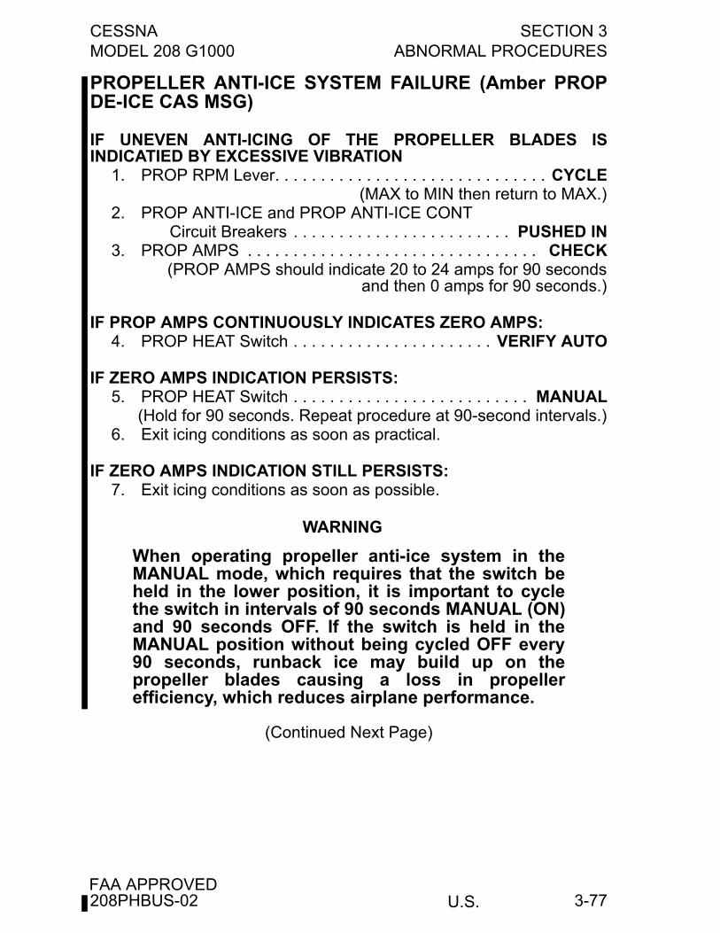
CESSNA SECTION 3MODEL 208 G1000 ABNORMAL PROCEDURES
U.S.FAA APPROVED
3-77
PROPELLER ANTI-ICE SYSTEM FAILURE (Amber PROPDE-ICE CAS MSG)
IF UNEVEN ANTI-ICING OF THE PROPELLER BLADES ISINDICATIED BY EXCESSIVE VIBRATION
1. PROP RPM Lever. . . . . . . . . . . . . . . . . . . . . . . . . . . . . . CYCLE(MAX to MIN then return to MAX.)
2. PROP ANTI-ICE and PROP ANTI-ICE CONT Circuit Breakers . . . . . . . . . . . . . . . . . . . . . . . . PUSHED IN
3. PROP AMPS . . . . . . . . . . . . . . . . . . . . . . . . . . . . . . . . CHECK(PROP AMPS should indicate 20 to 24 amps for 90 seconds
and then 0 amps for 90 seconds.)
IF PROP AMPS CONTINUOUSLY INDICATES ZERO AMPS:4. PROP HEAT Switch . . . . . . . . . . . . . . . . . . . . . . VERIFY AUTO
IF ZERO AMPS INDICATION PERSISTS:5. PROP HEAT Switch . . . . . . . . . . . . . . . . . . . . . . . . . . MANUAL
(Hold for 90 seconds. Repeat procedure at 90-second intervals.)6. Exit icing conditions as soon as practical.
IF ZERO AMPS INDICATION STILL PERSISTS:7. Exit icing conditions as soon as possible.
WARNING
When operating propeller anti-ice system in theMANUAL mode, which requires that the switch beheld in the lower position, it is important to cyclethe switch in intervals of 90 seconds MANUAL (ON)and 90 seconds OFF. If the switch is held in theMANUAL position without being cycled OFF every90 seconds, runback ice may build up on thepropeller blades causing a loss in propellerefficiency, which reduces airplane performance.
(Continued Next Page)
208PHBUS-02
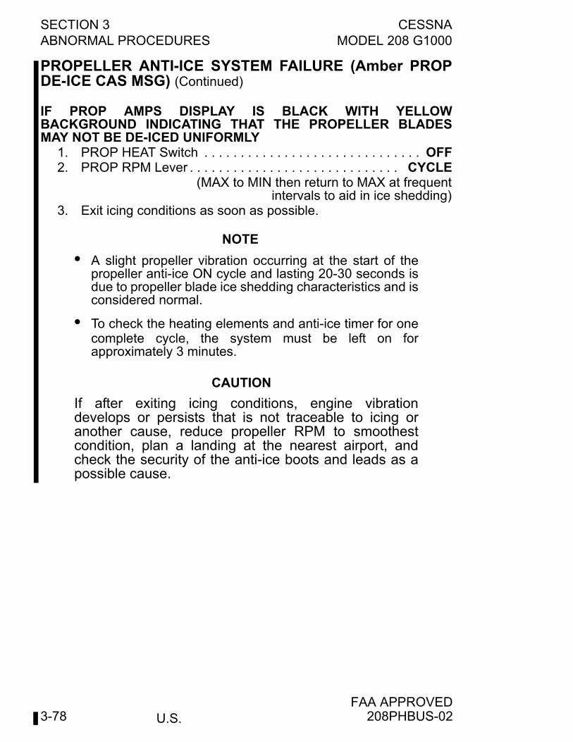
U.S.
SECTION 3 CESSNAABNORMAL PROCEDURES MODEL 208 G1000
FAA APPROVED3-78
PROPELLER ANTI-ICE SYSTEM FAILURE (Amber PROPDE-ICE CAS MSG) (Continued)
IF PROP AMPS DISPLAY IS BLACK WITH YELLOWBACKGROUND INDICATING THAT THE PROPELLER BLADESMAY NOT BE DE-ICED UNIFORMLY
1. PROP HEAT Switch . . . . . . . . . . . . . . . . . . . . . . . . . . . . . . OFF2. PROP RPM Lever . . . . . . . . . . . . . . . . . . . . . . . . . . . . . CYCLE
(MAX to MIN then return to MAX at frequentintervals to aid in ice shedding)
3. Exit icing conditions as soon as possible.
NOTE
• A slight propeller vibration occurring at the start of thepropeller anti-ice ON cycle and lasting 20-30 seconds isdue to propeller blade ice shedding characteristics and isconsidered normal.
• To check the heating elements and anti-ice timer for onecomplete cycle, the system must be left on forapproximately 3 minutes.
CAUTION
If after exiting icing conditions, engine vibrationdevelops or persists that is not traceable to icing oranother cause, reduce propeller RPM to smoothestcondition, plan a landing at the nearest airport, andcheck the security of the anti-ice boots and leads as apossible cause.
208PHBUS-02
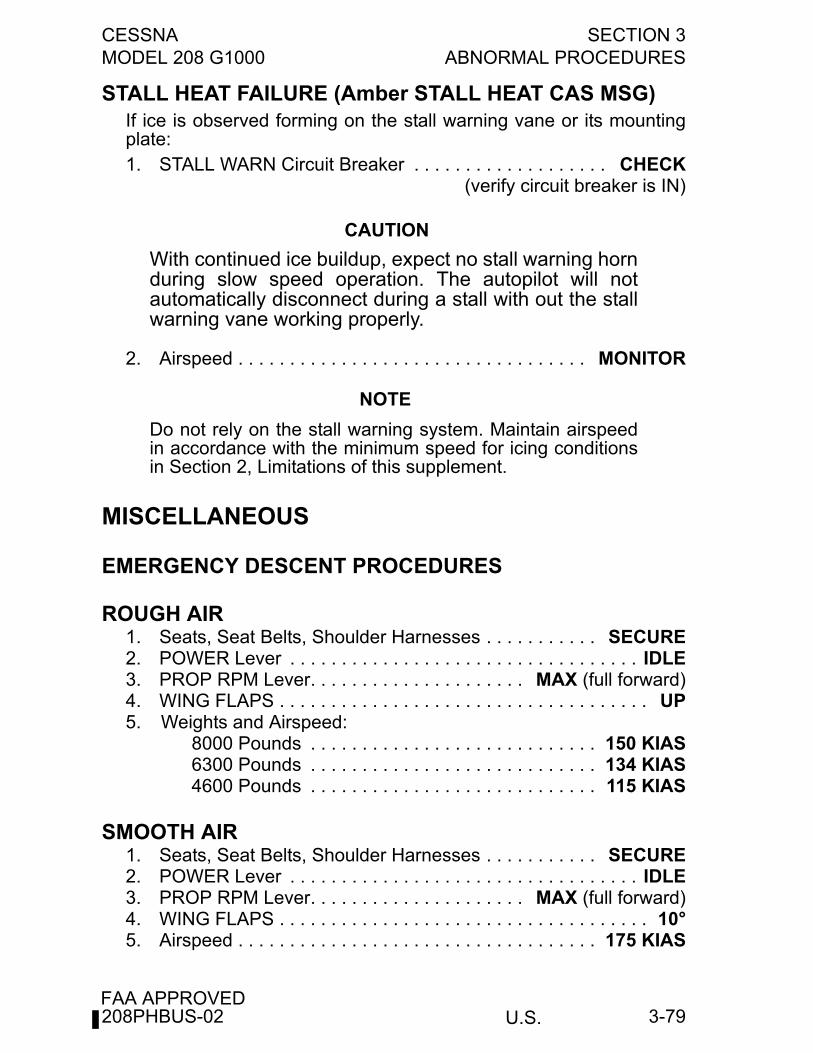
CESSNA SECTION 3MODEL 208 G1000 ABNORMAL PROCEDURES
U.S.FAA APPROVED
3-79
STALL HEAT FAILURE (Amber STALL HEAT CAS MSG)If ice is observed forming on the stall warning vane or its mountingplate:1. STALL WARN Circuit Breaker . . . . . . . . . . . . . . . . . . . CHECK
(verify circuit breaker is IN)
CAUTION
With continued ice buildup, expect no stall warning hornduring slow speed operation. The autopilot will notautomatically disconnect during a stall with out the stallwarning vane working properly.
2. Airspeed . . . . . . . . . . . . . . . . . . . . . . . . . . . . . . . . . . MONITOR
NOTE
Do not rely on the stall warning system. Maintain airspeedin accordance with the minimum speed for icing conditionsin Section 2, Limitations of this supplement.
MISCELLANEOUS
EMERGENCY DESCENT PROCEDURES
ROUGH AIR1. Seats, Seat Belts, Shoulder Harnesses . . . . . . . . . . . SECURE2. POWER Lever . . . . . . . . . . . . . . . . . . . . . . . . . . . . . . . . . . IDLE3. PROP RPM Lever. . . . . . . . . . . . . . . . . . . . . MAX (full forward)4. WING FLAPS . . . . . . . . . . . . . . . . . . . . . . . . . . . . . . . . . . . . UP5. Weights and Airspeed:
8000 Pounds . . . . . . . . . . . . . . . . . . . . . . . . . . . . 150 KIAS6300 Pounds . . . . . . . . . . . . . . . . . . . . . . . . . . . . 134 KIAS4600 Pounds . . . . . . . . . . . . . . . . . . . . . . . . . . . . 115 KIAS
SMOOTH AIR1. Seats, Seat Belts, Shoulder Harnesses . . . . . . . . . . . SECURE2. POWER Lever . . . . . . . . . . . . . . . . . . . . . . . . . . . . . . . . . . IDLE3. PROP RPM Lever. . . . . . . . . . . . . . . . . . . . . MAX (full forward)4. WING FLAPS . . . . . . . . . . . . . . . . . . . . . . . . . . . . . . . . . . . . 10°5. Airspeed . . . . . . . . . . . . . . . . . . . . . . . . . . . . . . . . . . . 175 KIAS
208PHBUS-02
U.S.
SECTION 3 CESSNAABNORMAL PROCEDURES MODEL 208 G1000
FAA APPROVED3-80
EXPANDED ABNORMAL
ELEVATOR MISTRIMIndicates a mistrim of the elevator while the autopilot is engaged. Theautopilot will normally trim automatically as required. However, duringrapid acceleration, deceleration, or configuration changes, momentaryillumination of this message may occur accompanied by minorfluctuations in the flight path. If the autopilot is disconnected while thismessage is displayed, high elevator control forces are possible. In theevent of a sustained illumination, the following procedure should befollowed:
ALTITUDE MISCOMPAREThis message is displayed when the G1000 detects a difference of 200feet or greater between the pilot’s and copilot’s altitude information(displayed in the upper right of the PFD). Refer to GARMIN G1000Cockpit Reference Guide for additional information.
AIRSPEED MISCOMPAREThis message is displayed when the G1000 detects a difference of 7KIAS or greater between the pilot’s and copilot’s airspeed information(10 KIAS difference during takeoff or landing roll). Refer to GARMING1000 Cockpit Reference Guide for additional information.
DUAL GPS FAILUREWhen both GPS receivers are inoperative, the G1000 system will enterone of two modes: Dead Reckoning mode (DR) or Loss Of Integritymode (LOI). The mode is indicated on the HSI by an amber “DR” or“LOI”. Which mode is active depends on the distance from thedestination airport in the active flight plan.
TRANSPONDER FAILURETransponder failure may be indicated by a red “X” across thetransponder display or failure of the transponder to accept codes ormode changes from the PFD.
208PHBUS-02
CESSNA SECTION 3MODEL 208 G1000 ABNORMAL PROCEDURES
U.S.FAA APPROVED
3-81
FAILED ATTITUDE AND/OR HEADING
This message indicates a loss of pitch, roll, and/or heading informationfrom AHRS. Refer to GARMIN G1000 Cockpit Reference Guide foradditional information. Interference from GPS repeaters operatinginside nearby hangars can cause an intermittent loss of attitude andheading displays while the aircraft is on the ground. This is usuallyaccompanied by a BOTH ON GPS1/2 message. Moving the aircraftmore than 100 yards away from the source of the interference shouldalleviate the condition.
BOTH ON ADC1/2This message is displayed on both PFDs and indicates that both pilot’sand copilot’s PFDs are displaying data from the same Air DataComputer. Normally the pilot’s side displays ADC1 and the copilot’sside displays ADC 2. Refer to GARMIN G1000 Cockpit ReferenceGuide for additional information.
BOTH ON AHRS1/2This message is displayed on both PFDs and indicates that both pilot’sand copilot’s PFDs are displaying data from the same Attitude HeadingReference System. Normally the pilot’s side displays AHRS1 and thecopilot’s side displays AHRS 2. Refer to GARMIN G1000 CockpitReference Guide for additional information.
XSIDE ADCThis message is displayed on both PFDs and indicates that both PFDsare displaying data from the opposite side Air Data Computer. Normallythe pilot’s side displays ADC1 and the copilot’s side displays ADC 2.Refer to GARMIN G1000 Cockpit Reference Guide for additionalinformation.
208PHBUS-02
U.S.
SECTION 3 CESSNAABNORMAL PROCEDURES MODEL 208 G1000
FAA APPROVED3-82
XSIDE AHRSThis message is displayed on both PFDs and indicates that both PFDsare displaying data from the opposite side Attitude Heading ReferenceSystem. Normally the pilot’s side displays ADC1 and the copilot’s sidedisplays ADC 2. Refer to GARMIN G1000 Cockpit Reference Guide foradditional information.
MULTI-FUNCTION DISPLAY FAN FAILEDAn overheat condition may arise in the associated display. In this case,screen brightness will be reduced automatically by 50% to lowerinternal temperature. Use reversionary capabilities, if necessary.
PRIMARY FLIGHT DISPLAY 1 FAN FAILEDAn overheat condition may arise in the associated display. In this case,screen brightness will be reduced automatically by 50% to lowerinternal temperature. Use reversionary capabilities, if necessary.
PRIMARY FLIGHT DISPLAY 2 FAN FAILEDAn overheat condition may arise in the associated display. In this case,screen brightness will be reduced automatically by 50% to lowerinternal temperature. Use reversionary capabilities, if necessary.
INADVERTENT OPENING OF AIRPLANE DOORS INFLIGHTIf any of the airplane doors should inadvertently open in flight, theairplane should be slowed to 125 KIAS or less to reduce buffeting of thedoors. If the upper cargo door is open, slow to 100 KIAS or less andlower flaps to full down so that wing downwash will move the doortowards its normally closed position. Closing the upper cargo door (orupper half of the passenger door on the Standard 208) can beaccomplished after airspeed has been reduced by pulling the doorforcefully closed and latching the door. If the door cannot be closed inflight, a landing should be made as soon as practical in accordancewith the checklist procedures. On Cargo Versions, an open cargo doorcannot be closed in flight since the inside of the upper door has nohandle.If any cargo pod doors inadvertently open in flight, the airplane shouldbe slowed to 125 KIAS or less and landed as soon as practical. Duringthe landing, avoid a nose-high flare to prevent dragging an open rearcargo pod door on the runway.
208PHBUS-02
CESSNA SECTION 4MODEL 208 G1000 NORMAL PROCEDURES
U.S.FAA APPROVED
4-1
NORMAL PROCEDURES
TABLE OF CONTENTSPage
Introduction . . . . . . . . . . . . . . . . . . . . . . . . . . . . . . . . . . . . . . . . . . . .4-3Airspeeds for Normal Operation . . . . . . . . . . . . . . . . . . . . . . . . . . . .4-3
CHECKLIST PROCEDURESPreflight Inspection Warnings . . . . . . . . . . . . . . . . . . . . . . . . . . . . . .4-5Preflight Inspection . . . . . . . . . . . . . . . . . . . . . . . . . . . . . . . . . . . . . .4-6
Preflight Inspection . . . . . . . . . . . . . . . . . . . . . . . . . . . . . . . . . . . .4-6Cabin. . . . . . . . . . . . . . . . . . . . . . . . . . . . . . . . . . . . . . . . . . . . . . .4-6Left Side . . . . . . . . . . . . . . . . . . . . . . . . . . . . . . . . . . . . . . . . . . . .4-8Left Wing, Leading Edge. . . . . . . . . . . . . . . . . . . . . . . . . . . . . . . .4-8Left Wing, Trailing Edge . . . . . . . . . . . . . . . . . . . . . . . . . . . . . . .4-10Measured Fuel Depth vs. Fuel Quantity . . . . . . . . . . . . . . . . . . . 4-11Empennage. . . . . . . . . . . . . . . . . . . . . . . . . . . . . . . . . . . . . . . . .4-12Right Wing, Trailing Edge . . . . . . . . . . . . . . . . . . . . . . . . . . . . . .4-13Right Wing, Leading Edge . . . . . . . . . . . . . . . . . . . . . . . . . . . . .4-13Nose . . . . . . . . . . . . . . . . . . . . . . . . . . . . . . . . . . . . . . . . . . . . . .4-15
Before Starting Engine. . . . . . . . . . . . . . . . . . . . . . . . . . . . . . . . . . .4-17Starting Engine (Battery Start) . . . . . . . . . . . . . . . . . . . . . . . . . . . . .4-18Starting Engine (External Power Start) . . . . . . . . . . . . . . . . . . . . . .4-20Taxiing . . . . . . . . . . . . . . . . . . . . . . . . . . . . . . . . . . . . . . . . . . . . . . .4-22Before Takeoff . . . . . . . . . . . . . . . . . . . . . . . . . . . . . . . . . . . . . . . . .4-22Takeoff . . . . . . . . . . . . . . . . . . . . . . . . . . . . . . . . . . . . . . . . . . . . . . .4-25
Normal Takeoff . . . . . . . . . . . . . . . . . . . . . . . . . . . . . . . . . . . . . .4-25Short Field Takeoff . . . . . . . . . . . . . . . . . . . . . . . . . . . . . . . . . . .4-25Type II, Type III or Type IV Anti-ice Fluid Takeoff . . . . . . . . . . . .4-26
Enroute Climb . . . . . . . . . . . . . . . . . . . . . . . . . . . . . . . . . . . . . . . . .4-26Cruise Climb . . . . . . . . . . . . . . . . . . . . . . . . . . . . . . . . . . . . . . . .4-26Maximum Performance Climb. . . . . . . . . . . . . . . . . . . . . . . . . . .4-27
Cruise . . . . . . . . . . . . . . . . . . . . . . . . . . . . . . . . . . . . . . . . . . . . . . .4-28Descent . . . . . . . . . . . . . . . . . . . . . . . . . . . . . . . . . . . . . . . . . . . . . .4-28Before Landing . . . . . . . . . . . . . . . . . . . . . . . . . . . . . . . . . . . . . . . .4-29Landing . . . . . . . . . . . . . . . . . . . . . . . . . . . . . . . . . . . . . . . . . . . . . .4-30
Normal Landing. . . . . . . . . . . . . . . . . . . . . . . . . . . . . . . . . . . . . .4-30Short Field Landing . . . . . . . . . . . . . . . . . . . . . . . . . . . . . . . . . . .4-30Balked Landing . . . . . . . . . . . . . . . . . . . . . . . . . . . . . . . . . . . . . .4-30
(Continued Next Page)
208PHBUS-02
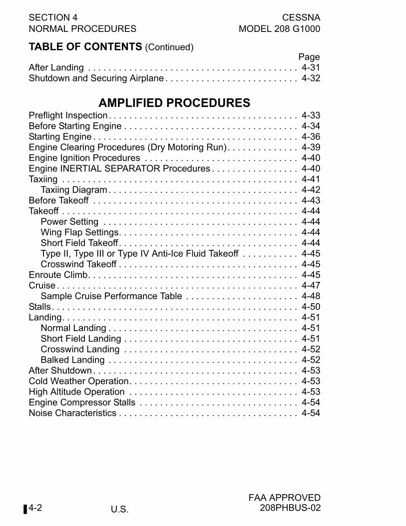
SECTION 4 CESSNANORMAL PROCEDURES MODEL 208 G1000
U.S.FAA APPROVED
4-2
TABLE OF CONTENTS (Continued)Page
After Landing . . . . . . . . . . . . . . . . . . . . . . . . . . . . . . . . . . . . . . . . . 4-31Shutdown and Securing Airplane . . . . . . . . . . . . . . . . . . . . . . . . . . 4-32
AMPLIFIED PROCEDURESPreflight Inspection. . . . . . . . . . . . . . . . . . . . . . . . . . . . . . . . . . . . . 4-33Before Starting Engine . . . . . . . . . . . . . . . . . . . . . . . . . . . . . . . . . . 4-34Starting Engine . . . . . . . . . . . . . . . . . . . . . . . . . . . . . . . . . . . . . . . . 4-36Engine Clearing Procedures (Dry Motoring Run). . . . . . . . . . . . . . 4-39Engine Ignition Procedures . . . . . . . . . . . . . . . . . . . . . . . . . . . . . . 4-40Engine INERTIAL SEPARATOR Procedures . . . . . . . . . . . . . . . . . 4-40Taxiing . . . . . . . . . . . . . . . . . . . . . . . . . . . . . . . . . . . . . . . . . . . . . . 4-41
Taxiing Diagram. . . . . . . . . . . . . . . . . . . . . . . . . . . . . . . . . . . . . 4-42Before Takeoff . . . . . . . . . . . . . . . . . . . . . . . . . . . . . . . . . . . . . . . . 4-43Takeoff . . . . . . . . . . . . . . . . . . . . . . . . . . . . . . . . . . . . . . . . . . . . . . 4-44
Power Setting . . . . . . . . . . . . . . . . . . . . . . . . . . . . . . . . . . . . . . 4-44Wing Flap Settings. . . . . . . . . . . . . . . . . . . . . . . . . . . . . . . . . . . 4-44Short Field Takeoff . . . . . . . . . . . . . . . . . . . . . . . . . . . . . . . . . . . 4-44Type II, Type III or Type IV Anti-Ice Fluid Takeoff . . . . . . . . . . . 4-45Crosswind Takeoff . . . . . . . . . . . . . . . . . . . . . . . . . . . . . . . . . . . 4-45
Enroute Climb. . . . . . . . . . . . . . . . . . . . . . . . . . . . . . . . . . . . . . . . . 4-45Cruise . . . . . . . . . . . . . . . . . . . . . . . . . . . . . . . . . . . . . . . . . . . . . . . 4-47
Sample Cruise Performance Table . . . . . . . . . . . . . . . . . . . . . . 4-48Stalls. . . . . . . . . . . . . . . . . . . . . . . . . . . . . . . . . . . . . . . . . . . . . . . . 4-50Landing. . . . . . . . . . . . . . . . . . . . . . . . . . . . . . . . . . . . . . . . . . . . . . 4-51
Normal Landing . . . . . . . . . . . . . . . . . . . . . . . . . . . . . . . . . . . . . 4-51Short Field Landing . . . . . . . . . . . . . . . . . . . . . . . . . . . . . . . . . . 4-51Crosswind Landing . . . . . . . . . . . . . . . . . . . . . . . . . . . . . . . . . . 4-52Balked Landing . . . . . . . . . . . . . . . . . . . . . . . . . . . . . . . . . . . . . 4-52
After Shutdown. . . . . . . . . . . . . . . . . . . . . . . . . . . . . . . . . . . . . . . . 4-53Cold Weather Operation. . . . . . . . . . . . . . . . . . . . . . . . . . . . . . . . . 4-53High Altitude Operation . . . . . . . . . . . . . . . . . . . . . . . . . . . . . . . . . 4-53Engine Compressor Stalls . . . . . . . . . . . . . . . . . . . . . . . . . . . . . . . 4-54Noise Characteristics . . . . . . . . . . . . . . . . . . . . . . . . . . . . . . . . . . . 4-54
208PHBUS-02
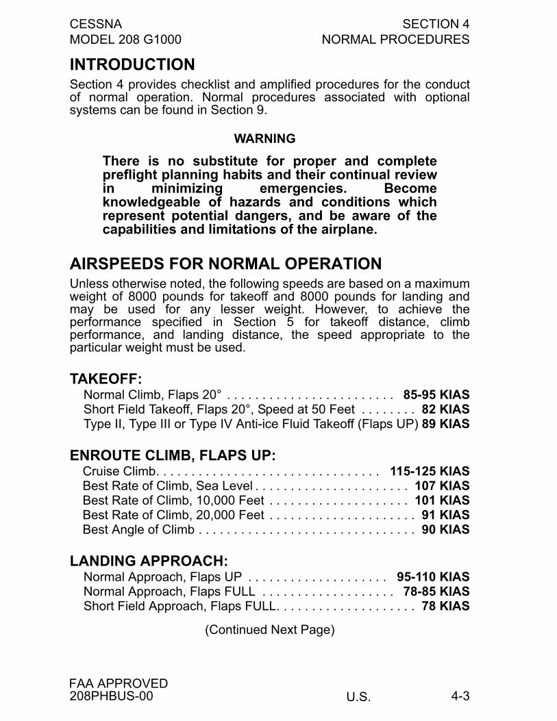
CESSNA SECTION 4MODEL 208 G1000 NORMAL PROCEDURES
U.S.FAA APPROVED
4-3
INTRODUCTIONSection 4 provides checklist and amplified procedures for the conductof normal operation. Normal procedures associated with optionalsystems can be found in Section 9.
WARNING
There is no substitute for proper and completepreflight planning habits and their continual reviewin minimizing emergencies. Becomeknowledgeable of hazards and conditions whichrepresent potential dangers, and be aware of thecapabilities and limitations of the airplane.
AIRSPEEDS FOR NORMAL OPERATIONUnless otherwise noted, the following speeds are based on a maximumweight of 8000 pounds for takeoff and 8000 pounds for landing andmay be used for any lesser weight. However, to achieve theperformance specified in Section 5 for takeoff distance, climbperformance, and landing distance, the speed appropriate to theparticular weight must be used.
TAKEOFF:Normal Climb, Flaps 20° . . . . . . . . . . . . . . . . . . . . . . . . 85-95 KIASShort Field Takeoff, Flaps 20°, Speed at 50 Feet . . . . . . . . 82 KIASType II, Type III or Type IV Anti-ice Fluid Takeoff (Flaps UP) 89 KIAS
ENROUTE CLIMB, FLAPS UP:Cruise Climb. . . . . . . . . . . . . . . . . . . . . . . . . . . . . . . . 115-125 KIASBest Rate of Climb, Sea Level . . . . . . . . . . . . . . . . . . . . . . 107 KIASBest Rate of Climb, 10,000 Feet . . . . . . . . . . . . . . . . . . . . 101 KIASBest Rate of Climb, 20,000 Feet . . . . . . . . . . . . . . . . . . . . . 91 KIASBest Angle of Climb . . . . . . . . . . . . . . . . . . . . . . . . . . . . . . . 90 KIAS
LANDING APPROACH:Normal Approach, Flaps UP . . . . . . . . . . . . . . . . . . . . 95-110 KIASNormal Approach, Flaps FULL . . . . . . . . . . . . . . . . . . . 78-85 KIASShort Field Approach, Flaps FULL. . . . . . . . . . . . . . . . . . . . 78 KIAS
(Continued Next Page)
208PHBUS-00
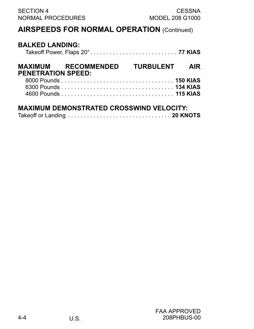
SECTION 4 CESSNANORMAL PROCEDURES MODEL 208 G1000
U.S.FAA APPROVED
4-4
AIRSPEEDS FOR NORMAL OPERATION (Continued)
BALKED LANDING:Takeoff Power, Flaps 20° . . . . . . . . . . . . . . . . . . . . . . . . . . . 77 KIAS
MAXIMUM RECOMMENDED TURBULENT AIRPENETRATION SPEED:
8000 Pounds . . . . . . . . . . . . . . . . . . . . . . . . . . . . . . . . . . . 150 KIAS6300 Pounds . . . . . . . . . . . . . . . . . . . . . . . . . . . . . . . . . . . 134 KIAS4600 Pounds . . . . . . . . . . . . . . . . . . . . . . . . . . . . . . . . . . . 115 KIAS
MAXIMUM DEMONSTRATED CROSSWIND VELOCITY:Takeoff or Landing . . . . . . . . . . . . . . . . . . . . . . . . . . . . . . . . 20 KNOTS
208PHBUS-00
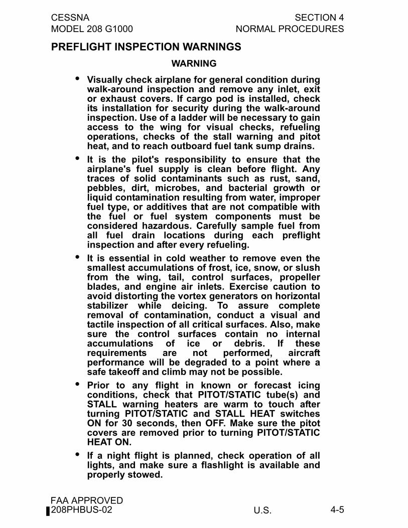
CESSNA SECTION 4MODEL 208 G1000 NORMAL PROCEDURES
U.S.FAA APPROVED
4-5
PREFLIGHT INSPECTION WARNINGS
WARNING
• Visually check airplane for general condition duringwalk-around inspection and remove any inlet, exitor exhaust covers. If cargo pod is installed, checkits installation for security during the walk-aroundinspection. Use of a ladder will be necessary to gainaccess to the wing for visual checks, refuelingoperations, checks of the stall warning and pitotheat, and to reach outboard fuel tank sump drains.
• It is the pilot's responsibility to ensure that theairplane's fuel supply is clean before flight. Anytraces of solid contaminants such as rust, sand,pebbles, dirt, microbes, and bacterial growth orliquid contamination resulting from water, improperfuel type, or additives that are not compatible withthe fuel or fuel system components must beconsidered hazardous. Carefully sample fuel fromall fuel drain locations during each preflightinspection and after every refueling.
• It is essential in cold weather to remove even thesmallest accumulations of frost, ice, snow, or slushfrom the wing, tail, control surfaces, propellerblades, and engine air inlets. Exercise caution toavoid distorting the vortex generators on horizontalstabilizer while deicing. To assure completeremoval of contamination, conduct a visual andtactile inspection of all critical surfaces. Also, makesure the control surfaces contain no internalaccumulations of ice or debris. If theserequirements are not performed, aircraftperformance will be degraded to a point where asafe takeoff and climb may not be possible.
• Prior to any flight in known or forecast icingconditions, check that PITOT/STATIC tube(s) andSTALL warning heaters are warm to touch afterturning PITOT/STATIC and STALL HEAT switchesON for 30 seconds, then OFF. Make sure the pitotcovers are removed prior to turning PITOT/STATICHEAT ON.
• If a night flight is planned, check operation of alllights, and make sure a flashlight is available andproperly stowed.
208PHBUS-02
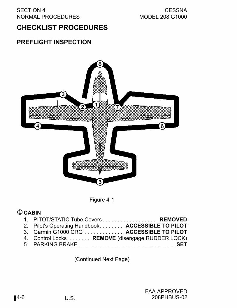
SECTION 4 CESSNANORMAL PROCEDURES MODEL 208 G1000
U.S.FAA APPROVED
4-6
CHECKLIST PROCEDURES
PREFLIGHT INSPECTION
CABIN1. PITOT/STATIC Tube Covers . . . . . . . . . . . . . . . . . . REMOVED2. Pilot's Operating Handbook. . . . . . . . ACCESSIBLE TO PILOT3. Garmin G1000 CRG . . . . . . . . . . . . . ACCESSIBLE TO PILOT4. Control Locks . . . . . . . REMOVE (disengage RUDDER LOCK)5. PARKING BRAKE . . . . . . . . . . . . . . . . . . . . . . . . . . . . . . . . SET
(Continued Next Page)
Figure 4-1
208PHBUS-02
CESSNA SECTION 4MODEL 208 G1000 NORMAL PROCEDURES
U.S.FAA APPROVED
4-7
CABIN (Continued)6. All Switches . . . . . . . . . . . . . . . . . . . . . . . . . . . . . . . . . . . . OFF7. Circuit Breakers . . . . . . . . . . . . . . . . . . . . . . . . . . . . . . . . . . . IN8. ALT STATIC AIR . . . . . . . . . . . . . . . . . . . . . . . . . . . . . . . . . OFF9. INERTIAL SEPARATOR T-Handle . . . . . . . . . . . . . . . NORMAL10. STBY FLAP MOTOR Switch . . . . . . . . . . . . GUARDED NORM11. OXYGEN SUPPLY PRESSURE (if installed) . . . . . . . . CHECK12. Oxygen Masks (if installed). . . . . . . . . . . . CHECK AVAILABLE13. FUEL TANK SELECTOR Valves . . . . . . . . . . . . . . . BOTH ON
(feel against stop)14. VENTILATION FANS/ AIR CONDITIONING (if installed) . . OFF15. BLEED AIR HEAT Switch . . . . . . . . . . . . . . . . . . . . OFF (down)16. EMERGENCY POWER Lever . . . . . . . . . . . . . . . . . . NORMAL17. TRIM Controls. . . . . . . . . . . . . . . . . . . . . . . . . . . . . . . . . . . SET18. FUEL SHUTOFF Knob . . . . . . . . . . . . . . . . . . . . . . ON (push in)19. CABIN HEAT FIREWALL SHUTOFF Control . . . . . . CHECK IN20. BATTERY Switch . . . . . . . . . . . . . . . . . . . . . . . . . . . . . . . . . ON
(verify deck skin fans audible and airflow from each fan)21. AVIONICS No. 1 Switch . . . . . . . . . . . . . . . . . . . . . . . . . . . . ON22. PFD 1 . . . . . . . . . . . . . . . . . . . . . . . CHECK (verify PFD 1 - ON)23. AVIONICS No. 2 Switch . . . . . . . . . . . . . . . . . . . . . . . . . . . . ON24. PFD 2 and MFD . . . . . . . CHECK (verify PFD2 and MFD - ON)25. FUEL QTY . . . . . . . . . . . . . . . . . . . . . . . . . CHECK QUANTITY26. ENGINE Softkey . . . . . . . . . . . . . . . . . . . . . . SELECT SYSTEM27. SYSTEM Softkey . . . . . . . . . . . . . . . . . . RST FUEL (if desired)Reset Fuel Totalizer if desired. Select ENGINE Softkey to return tomain page.28. WING FLAPS Handle . . . . . . . . . . . . . . . . . . . . . . FULL DOWN29. PITOT/STATIC and
STALL HEAT Switches . . . . . . . . . . ON FOR 30 SECONDS;THEN OFF
30. AVIONICS No. 1 and No. 2 Switches . . . . . . . . . . . . . . . . . OFF31. BATTERY Switch . . . . . . . . . . . . . . . . . . . . . . . . . . . . . . . . OFF
208PHBUS-00
SECTION 4 CESSNANORMAL PROCEDURES MODEL 208 G1000
U.S.FAA APPROVED
4-8
LEFT SIDE1. WING LIGHT. . . . . . . . . . . . . . . . . . . CHECK (verify condition)2. Fuel Reservoir Drain (bottom of fuselage
or left side of cargo pod) . . . . . . . . . DRAIN (using fuel sampler)Drain to check for water, sediment, and proper fuel before eachflight and after each refueling. If water is observed, takeadditional samples until clear. Take repeated samples from allfuel drain points (see Section 7, Fuel System Schematic for allnine drain locations) until all contamination has been removed.
NOTE
Properly dispose of samples from all fuel drains. Aviationturbine fuel will deteriorate asphalt surfaces.
3. Main Landing Gear . . . . . . . . . . . . . . . . . . . . . . . . . . . . CHECK(check proper tire inflation and condition of gear)
4. Inboard Fuel Tank Sump and External SumpQuick-Drain Valves . . . . . . . . . . DRAIN (using fuel sampler)
Drain to check for water, sediment, and proper fuel before eachflight and after each refueling. If water is observed, takeadditional samples until clear. Take repeated samples from allfuel drain points until all contamination has been removed.
LEFT WING Leading Edge
WARNING
It is essential in cold weather to remove even thesmallest accumulations of frost, ice, snow, or slushfrom the wing and control surfaces. To assurecomplete removal of contamination, conduct avisual and tactile inspection up to two feet behindthe protected surfaces at one location along thewing span as a minimum. Also, make sure thecontrol surfaces contain no internal accumulationsof ice or debris. If these requirements are notperformed, aircraft performance will be degraded toa point where a safe takeoff and climb may not bepossible.
(Continued Next Page)
208PHBUS-00
CESSNA SECTION 4MODEL 208 G1000 NORMAL PROCEDURES
U.S.FAA APPROVED
4-9
LEFT WING Leading Edge (Continued)
WARNING
• Prior to any flight in known or forecast icingconditions, check that PITOT/STATIC tube(s) andSTALL warning heaters are warm to touch afterturning PITOT/STATIC and STALL HEAT switchesON for 30 seconds, then OFF. Make sure the pitotcovers are removed prior to turning PITOT/STATIC HEAT ON.
1. Wing Tie-Down . . . . . . . . . . . . . . . . . . . . . . . . . . DISCONNECT2. Stall Warning Vane . . . . . . . . . . . . . . . . . . . . . . . . . . . . CHECK
(verify freedom of movement, audible warning and warmth)Ensure the elevator control is off the forward stop in order tocheck audible warning.
3. PITOT/STATIC Tube. . . . . . . . . . . . . . . . . . . . . . . . . . . CHECK(verify security, openings for stoppage and warmth)
4. LDG and TAXI/RECOG Lights . . . . . . . . . . . . . . . . . . . CHECK(verify condition and cleanliness)
5. Fuel Quantity . . . . . . . . . . . . . . . . . . . . . . . VISUALLY CHECKSee Measured Fuel Depth vs. Fuel Quantity chart in Section 4.
6. Fuel Filler Cap . . . . . . . . . . . . . . . . . . . . . . . . . . . . . . SECURE7. Outboard Fuel Tank Sump
Quick-Drain Valve. . . . . . . . . . . DRAIN (using fuel sampler)Drain to check for water, sediment and proper fuel before eachflight and after each refueling. If water is observed, takeadditional samples until clear. Take repeated samples from allfuel drain points until all contamination has been removed.
8. NAV and STROBE Lights . . . . . . . . . . . . . . . . . . . . . . . CHECK(verify condition and cleanliness)
208PHBUS-02
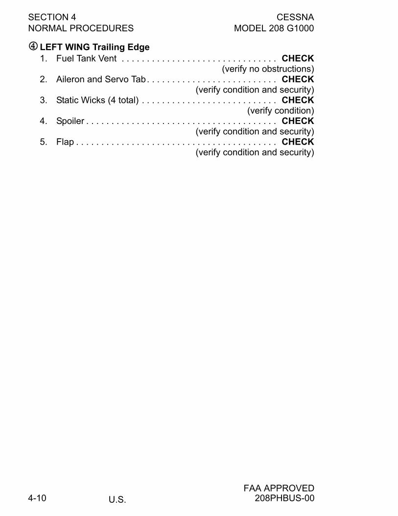
SECTION 4 CESSNANORMAL PROCEDURES MODEL 208 G1000
U.S.FAA APPROVED
4-10
LEFT WING Trailing Edge1. Fuel Tank Vent . . . . . . . . . . . . . . . . . . . . . . . . . . . . . . . CHECK
(verify no obstructions)2. Aileron and Servo Tab. . . . . . . . . . . . . . . . . . . . . . . . . . CHECK
(verify condition and security)3. Static Wicks (4 total) . . . . . . . . . . . . . . . . . . . . . . . . . . . CHECK
(verify condition)4. Spoiler . . . . . . . . . . . . . . . . . . . . . . . . . . . . . . . . . . . . . . CHECK
(verify condition and security)5. Flap . . . . . . . . . . . . . . . . . . . . . . . . . . . . . . . . . . . . . . . . CHECK
(verify condition and security)
208PHBUS-00
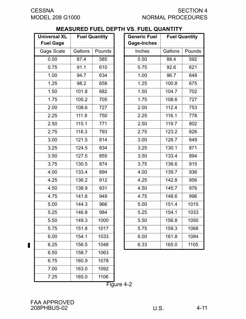
CESSNA SECTION 4MODEL 208 G1000 NORMAL PROCEDURES
U.S.FAA APPROVED
4-11
MEASURED FUEL DEPTH VS. FUEL QUANTITYUniversal XL
Fuel GageFuel Quantity Generic Fuel
Gage-InchesFuel Quantity
Gage Scale Gallons Pounds Inches Gallons Pounds
0.50 87.4 585 0.50 88.4 592
0.75 91.1 610 0.75 92.6 621
1.00 94.7 634 1.00 96.7 648
1.25 98.2 658 1.25 100.8 675
1.50 101.8 682 1.50 104.7 702
1.75 105.2 705 1.75 108.6 727
2.00 108.6 727 2.00 112.4 753
2.25 111.9 750 2.25 116.1 778
2.50 115.1 771 2.50 119.7 802
2.75 118.3 793 2.75 123.2 826
3.00 121.5 814 3.00 126.7 849
3.25 124.5 834 3.25 130.1 871
3.50 127.5 855 3.50 133.4 894
3.75 130.5 874 3.75 136.6 915
4.00 133.4 894 4.00 139.7 936
4.25 136.2 912 4.25 142.8 956
4.50 138.9 931 4.50 145.7 976
4.75 141.6 949 4.75 148.6 996
5.00 144.3 966 5.00 151.4 1015
5.25 146.8 984 5.25 154.1 1033
5.50 149.3 1000 5.50 156.8 1050
5.75 151.8 1017 5.75 159.3 1068
6.00 154.1 1033 6.00 161.8 1084
6.25 156.5 1048 6.33 165.0 1105
6.50 158.7 1063
6.75 160.9 1078
7.00 163.0 1092
7.25 165.0 1106
Figure 4-2
208PHBUS-02
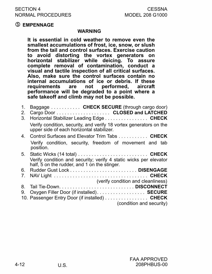
SECTION 4 CESSNANORMAL PROCEDURES MODEL 208 G1000
U.S.FAA APPROVED
4-12
EMPENNAGEWARNING
It is essential in cold weather to remove even thesmallest accumulations of frost, ice, snow, or slushfrom the tail and control surfaces. Exercise cautionto avoid distorting the vortex generators onhorizontal stabilizer while deicing. To assurecomplete removal of contamination, conduct avisual and tactile inspection of all critical surfaces.Also, make sure the control surfaces contain nointernal accumulations of ice or debris. If theserequirements are not performed, aircraftperformance will be degraded to a point where asafe takeoff and climb may not be possible.
1. Baggage . . . . . . . . . . . CHECK SECURE (through cargo door)2. Cargo Door . . . . . . . . . . . . . . . . . . . . CLOSED and LATCHED3. Horizontal Stabilizer Leading Edge . . . . . . . . . . . . . . . . CHECK
Verify condition, security, and verify 18 vortex generators on theupper side of each horizontal stabilizer.
4. Control Surfaces and Elevator Trim Tabs . . . . . . . . . . . CHECKVerify condition, security, freedom of movement and tabposition.
5. Static Wicks (14 total) . . . . . . . . . . . . . . . . . . . . . . . . . . CHECKVerify condition and security; verify 4 static wicks per elevatorhalf, 5 on the rudder, and 1 on the stinger.
6. Rudder Gust Lock . . . . . . . . . . . . . . . . . . . . . . . . . DISENGAGE7. NAV Light . . . . . . . . . . . . . . . . . . . . . . . . . . . . . . . . . . . CHECK
(verify condition and cleanliness)8. Tail Tie-Down. . . . . . . . . . . . . . . . . . . . . . . . . . . . DISCONNECT9. Oxygen Filler Door (if installed) . . . . . . . . . . . . . . . . . . SECURE10. Passenger Entry Door (if installed) . . . . . . . . . . . . . . . . CHECK
(condition and security)
208PHBUS-00
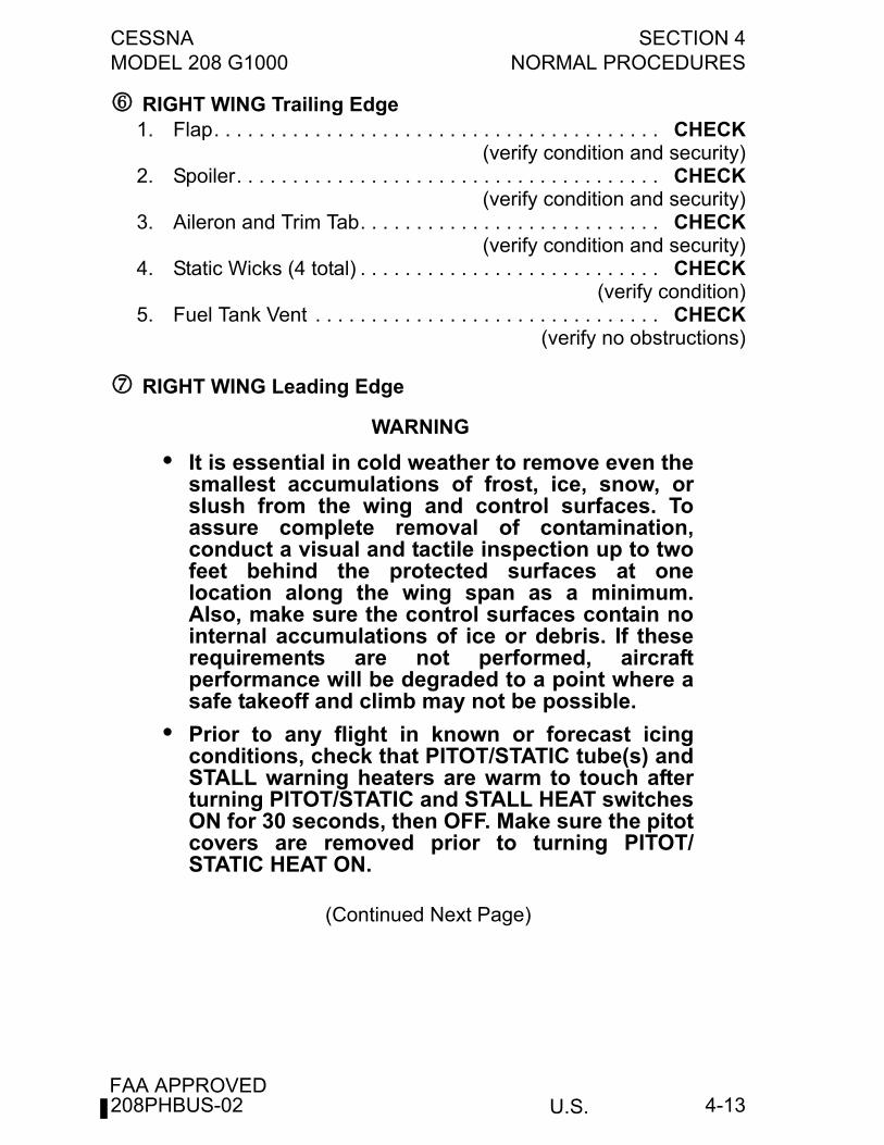
CESSNA SECTION 4MODEL 208 G1000 NORMAL PROCEDURES
U.S.FAA APPROVED
4-13
RIGHT WING Trailing Edge1. Flap. . . . . . . . . . . . . . . . . . . . . . . . . . . . . . . . . . . . . . . . CHECK
(verify condition and security)2. Spoiler. . . . . . . . . . . . . . . . . . . . . . . . . . . . . . . . . . . . . . CHECK
(verify condition and security)3. Aileron and Trim Tab. . . . . . . . . . . . . . . . . . . . . . . . . . . CHECK
(verify condition and security)4. Static Wicks (4 total) . . . . . . . . . . . . . . . . . . . . . . . . . . . CHECK
(verify condition)5. Fuel Tank Vent . . . . . . . . . . . . . . . . . . . . . . . . . . . . . . . CHECK
(verify no obstructions)
RIGHT WING Leading Edge
WARNING
• It is essential in cold weather to remove even thesmallest accumulations of frost, ice, snow, orslush from the wing and control surfaces. Toassure complete removal of contamination,conduct a visual and tactile inspection up to twofeet behind the protected surfaces at onelocation along the wing span as a minimum.Also, make sure the control surfaces contain nointernal accumulations of ice or debris. If theserequirements are not performed, aircraftperformance will be degraded to a point where asafe takeoff and climb may not be possible.
• Prior to any flight in known or forecast icingconditions, check that PITOT/STATIC tube(s) andSTALL warning heaters are warm to touch afterturning PITOT/STATIC and STALL HEAT switchesON for 30 seconds, then OFF. Make sure the pitotcovers are removed prior to turning PITOT/STATIC HEAT ON.
(Continued Next Page)
208PHBUS-02
SECTION 4 CESSNANORMAL PROCEDURES MODEL 208 G1000
U.S.FAA APPROVED
4-14
RIGHT WING Leading Edge (Continued)1. NAV and STROBE Lights . . . . . . . . . . . . . . . . . . . . . . . CHECK
(verify condition and cleanliness)2. Fuel Quantity . . . . . . . . . . . . . . . . . . . . . . . . VISUALLY CHECK
See Measured Fuel Depth vs. Fuel Quantity chart in Section 4.3. Fuel Filler Cap. . . . . . . . . . . . . . . . . . . . . . . . . . . . . . . SECURE4. Outboard Fuel Tank Sump Quick-Drain Valve
(if airplane parked with onewing low on a sloping ramp) . . . DRAIN (using fuel sampler)
Drain to check for water, sediment and proper fuel before eachflight and after each refueling. If water is observed, takeadditional samples until clear. Take repeated samples from allfuel drain points until all contamination has been removed.
5. LND and TAXI/ RECOG Lights . . . . . . . . . . . . . . . . . . . CHECK(verify condition and cleanliness)
6. PITOT/STATIC Tube . . . . . . . . . . . . . . . . . . . . . . . . . . . CHECK(verify security, openings for stoppage and warmth)
7. Radome (if installed) . . . . . . . . . . . . . . . . . . . . . . . . . . . CHECK (verify condition and security)
8. Wing Tie-Down . . . . . . . . . . . . . . . . . . . . . . . . . . DISCONNECT9. Inboard Fuel Tank Sump and External Sump
Quick-Drain Valves . . . . . . . . . . DRAIN (using fuel sampler)Drain to check for water, sediment, and proper fuel before eachflight and after each refueling. If water is observed, takeadditional samples until clear. Take repeated samples from allfuel drain points until all contamination has been removed.
10. Main Landing Gear . . . . . . . . . . . . . . . . . . . . . . . . . . . . CHECK(check proper tire inflation and condition of gear)
208PHBUS-02
CESSNA SECTION 4MODEL 208 G1000 NORMAL PROCEDURES
U.S.FAA APPROVED
4-15
NOSE
WARNING
It is essential in cold weather to remove even thesmallest accumulations of frost, ice, snow, or slushfrom the propeller blades and spinner, and the airinlets (starter/generator, oil cooler and engineinlets). To assure complete removal ofcontamination, conduct a visual and tactileinspection of all critical surfaces. If theserequirements are not performed, aircraftperformance will be degraded to a point where asafe takeoff and climb may not be possible.
1. Right Crew Door . . . . . . . . . . . . . . . . . . . . . . . . . . . . . CLOSED2. Exhaust Cover (if installed). . . . . . . . . . . . . . . . . . . . . REMOVE3. Cowling . . . . . . . . . . . . . . . . . . . . . . . . . . . . . . . . . . . . . . . OPEN
(right side of upper cowling for access andcheck condition and security)
4. Engine (right side). . . . . . . . . . . . . . . . . . . . . . . . . . . . . CHECK(verify general condition, security, fuel and oil
leakage and damage to any components)
WARNING
Avoid touching the output connectors or couplingnuts or ignition excitor with bare hands.
5. Battery . . . . . . . . . . . . . . . . . . . . . . . . . . . . . . . . . . . . . CHECK(verify condition and power cables security)
6. Exhaust System . . . . . . . . . . . . . . . . . . . . . . . . . . . . . . CHECK(verify condition, security, cracks, distortion and damage)
7. Cowling . . . . . . . . . . . . . . . . . . CLOSE and LATCH (right side)8. Propeller Anchor . . . . . . . . . . . . . . . . . . . . . . . . . . . . . REMOVE9. Air Inlet Covers . . . . . . . . . . . . . . . . . . . . . . . . . . . . . . REMOVE10. Air Inlets . . . . . . . . . . . . . . . . . . . . . . . . . . . . . . . . . . . . CHECK
Check starter/generator blast tube opening and oil cooler inlet(right) and engine induction air inlet (left) for condition,restrictions, and debris.
(Continued Next Page)
208PHBUS-00
SECTION 4 CESSNANORMAL PROCEDURES MODEL 208 G1000
U.S.FAA APPROVED
4-16
NOSE (Continued)11. Propeller . . . . . . . . . . . . . . . . . . . . . . . . . . . . . . . . . . . . CHECK
Inspect blades for nicks, gouges, looseness of material, erosionand cracks. Also, inspect blades for lightning strike (darkenedarea near tips), boots for security, condition and evidence ofgrease and oil leaks.
12. Propeller Spinner. . . . . . . . . . . . . . . . . . . . . . . . . . . . . . CHECK (verify condition and security)
13. Nose Wheel Strut and Tire . . . . . . . . . . . . . . . . . . . . . . CHECKCheck condition, red over-travel indicator block and cable intact(not fallen into view), and proper inflation of tire.
14. Cowling . . . . . . . . . . . . . . . . . . . . . . . . . . . . . . . . . . . . . . OPEN(left side of upper cowling for access and check condition andsecurity)
15. Engine (left side) . . . . . . . . . . . . . . . . . . . . . . . . . . . . . . CHECK(verify general condition, security, fuel, no oil leakage, and nodamage to any components)
16. INERTIAL SEPARATOR Bypass Outlet . . . . CHECK CLOSED(verify duct free of debris)
17. Oil Dipstick/Filler Cap . . . . . . . . . . . . . . . . . . . . . . . . . . CHECKCheck oil level. Check dipstick/ filler cap SECURE. Fill to within1 1/2 quarts of MAX HOT or MAX COLD (as appropriate) ondipstick. Markings indicate U.S. quarts low if oil is hot.
WARNING
Make sure the oil dipstick cap is securely latcheddown. Operating the engine with less than therecommended oil level and with the dipstick capunlatched will result in excessive oil loss andeventual engine stoppage.
18. Electrical Power Box Circuit Breakers and Diodes . . . . CHECK(verify all circuit breakers, including standby
alternators are IN and diodes are clear)19. Standby Alternator and Belt. . . . . . . . . . . . . CHECK (condition)20. Fuel Filter . . . . . . . . . . CHECK FUEL FILTER BYPASS FLAG
(for proper location - flush)
(Continued Next Page)
208PHBUS-01
CESSNA SECTION 4MODEL 208 G1000 NORMAL PROCEDURES
U.S.FAA APPROVED
4-17
NOSE (Continued)21. Brake Fluid Reservoir . . . . . . . . . . . . . . . . . . . . CHECK LEVEL22. Cowling . . . . . . . . . . . . . . . . . . . . CLOSE and LATCH (left side)23. Fuel Filter Quick-Drain Valve . . . . . DRAIN (using fuel sampler)
Drain to check for water, sediment, and proper fuel before eachflight and after each refueling. If water is observed, takeadditional samples until clear. Take repeated samples from allfuel drain points until all contamination has been removed.
24. Fuel Drain Can . . . . . . . . . . . . . . . . . . . . . . DRAIN (until empty)25. Fuel Pump Drain Reservoir . . . . . . . . . . . . DRAIN (until empty)
BEFORE STARTING ENGINE1. Preflight Inspection . . . . . . . . . . . . . . . . . . . . . . . . . COMPLETE
(verify weight and balance is checked and tail stand is removedand stowed)
2. All Key Locking Cabin Doors . . . . . . . . . . . . . . . . . UNLOCKED(except cargo configured aircraft)
Cargo door can be locked if no passengers occupy cargosection of airplane.
3. Passenger Briefing . . . . . . . . . . . . . . . . . . . . . . . . . COMPLETE4. Cabin Doors . . . . . . . . . . . . . . . . . LATCHED (check aft doors)5. Left Crew Door Lock Override Knob and
Right Crew Door Inside Lock . . . . . . . . . . . . . . UNLOCKED6. PARKING BRAKE. . . . . . . . . . . . . . . . . . . . . . . . . . . . . . . . SET
(depress brake pedals and pull control out)7. Control Lock . . . . . . . . . . . . . . . . . . . . . . . . . . . . . . . . REMOVE8. Seats, Seat Belts, Shoulder Harnesses ADJUST and SECURE
(crew seat lock indicator pin(s) extended)
WARNING
Failure to correctly use seat belts and shoulderharnesses could result in serious or fatal injury inthe event of an accident.
9. Switches . . . . . . . . . . . . . . . . . . . . . . . . . . . . . . . . . . . . . . . OFF10. IGNITION Switch . . . . . . . . . . . . . . . . . . . . . . . . . . . . . . NORM11. Circuit Breakers . . . . . . . . . . . . . . . . . . . . . . . . . . . . CHECK IN12. FUEL TANK SELECTORS . . . . . . . . . . . . . . . . . . . . BOTH ON13. VENTILATION FANS/ AIR CONDITIONING . . . . . . . . . . . OFF14. BLEED AIR HEAT Switch . . . . . . . . . . . . . . . . . . . . OFF (down)
(Continued Next Page)
208PHBUS-00
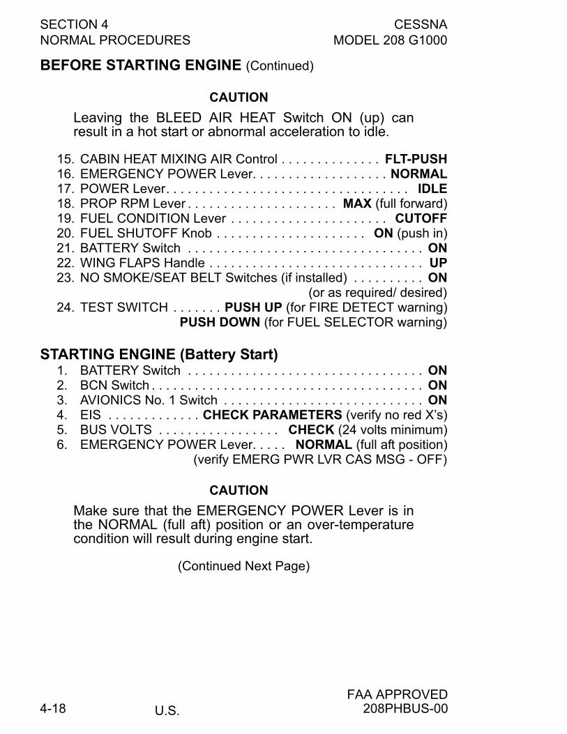
SECTION 4 CESSNANORMAL PROCEDURES MODEL 208 G1000
U.S.FAA APPROVED
4-18
BEFORE STARTING ENGINE (Continued)
CAUTION
Leaving the BLEED AIR HEAT Switch ON (up) canresult in a hot start or abnormal acceleration to idle.
15. CABIN HEAT MIXING AIR Control . . . . . . . . . . . . . . FLT-PUSH16. EMERGENCY POWER Lever. . . . . . . . . . . . . . . . . . . NORMAL17. POWER Lever. . . . . . . . . . . . . . . . . . . . . . . . . . . . . . . . . . IDLE18. PROP RPM Lever . . . . . . . . . . . . . . . . . . . . . MAX (full forward)19. FUEL CONDITION Lever . . . . . . . . . . . . . . . . . . . . . . CUTOFF20. FUEL SHUTOFF Knob . . . . . . . . . . . . . . . . . . . . . ON (push in)21. BATTERY Switch . . . . . . . . . . . . . . . . . . . . . . . . . . . . . . . . . ON22. WING FLAPS Handle . . . . . . . . . . . . . . . . . . . . . . . . . . . . . . UP23. NO SMOKE/SEAT BELT Switches (if installed) . . . . . . . . . . ON
(or as required/ desired)24. TEST SWITCH . . . . . . . PUSH UP (for FIRE DETECT warning)
PUSH DOWN (for FUEL SELECTOR warning)
STARTING ENGINE (Battery Start)1. BATTERY Switch . . . . . . . . . . . . . . . . . . . . . . . . . . . . . . . . . ON2. BCN Switch . . . . . . . . . . . . . . . . . . . . . . . . . . . . . . . . . . . . . . ON3. AVIONICS No. 1 Switch . . . . . . . . . . . . . . . . . . . . . . . . . . . . ON4. EIS . . . . . . . . . . . . . CHECK PARAMETERS (verify no red X’s)5. BUS VOLTS . . . . . . . . . . . . . . . . . CHECK (24 volts minimum)6. EMERGENCY POWER Lever. . . . . NORMAL (full aft position)
(verify EMERG PWR LVR CAS MSG - OFF)
CAUTION
Make sure that the EMERGENCY POWER Lever is inthe NORMAL (full aft) position or an over-temperaturecondition will result during engine start.
(Continued Next Page)
208PHBUS-00
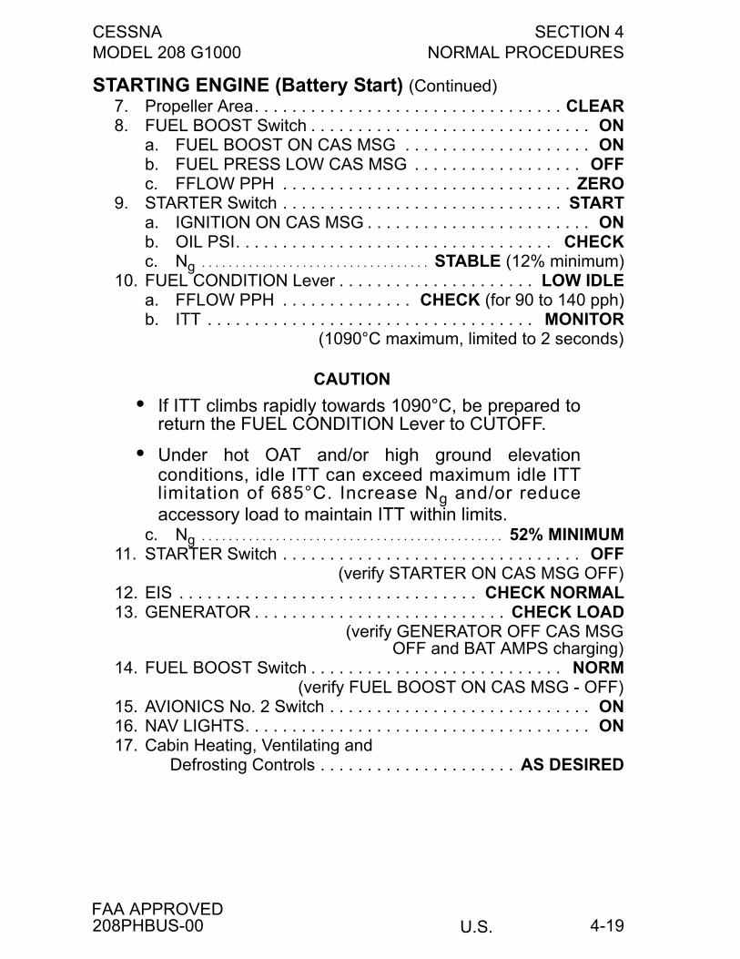
CESSNA SECTION 4MODEL 208 G1000 NORMAL PROCEDURES
U.S.FAA APPROVED
4-19
STARTING ENGINE (Battery Start) (Continued)7. Propeller Area. . . . . . . . . . . . . . . . . . . . . . . . . . . . . . . . . CLEAR8. FUEL BOOST Switch . . . . . . . . . . . . . . . . . . . . . . . . . . . . . . ON
a. FUEL BOOST ON CAS MSG . . . . . . . . . . . . . . . . . . . . ONb. FUEL PRESS LOW CAS MSG . . . . . . . . . . . . . . . . . . OFFc. FFLOW PPH . . . . . . . . . . . . . . . . . . . . . . . . . . . . . . . ZERO
9. STARTER Switch . . . . . . . . . . . . . . . . . . . . . . . . . . . . . . STARTa. IGNITION ON CAS MSG . . . . . . . . . . . . . . . . . . . . . . . . ONb. OIL PSI. . . . . . . . . . . . . . . . . . . . . . . . . . . . . . . . . . CHECKc. Ng . . . . . . . . . . . . . . . . . . . . . . . . . . . . . . . . . . STABLE (12% minimum)
10. FUEL CONDITION Lever . . . . . . . . . . . . . . . . . . . . . LOW IDLEa. FFLOW PPH . . . . . . . . . . . . . . CHECK (for 90 to 140 pph)b. ITT . . . . . . . . . . . . . . . . . . . . . . . . . . . . . . . . . . . MONITOR
(1090°C maximum, limited to 2 seconds)
CAUTION
• If ITT climbs rapidly towards 1090°C, be prepared toreturn the FUEL CONDITION Lever to CUTOFF.
• Under hot OAT and/or high ground elevationconditions, idle ITT can exceed maximum idle ITTlimitation of 685°C. Increase Ng and/or reduceaccessory load to maintain ITT within limits.
c. Ng . . . . . . . . . . . . . . . . . . . . . . . . . . . . . . . . . . . . . . . . . . . . . 52% MINIMUM11. STARTER Switch . . . . . . . . . . . . . . . . . . . . . . . . . . . . . . . . OFF
(verify STARTER ON CAS MSG OFF)12. EIS . . . . . . . . . . . . . . . . . . . . . . . . . . . . . . . . CHECK NORMAL13. GENERATOR . . . . . . . . . . . . . . . . . . . . . . . . . . . CHECK LOAD
(verify GENERATOR OFF CAS MSGOFF and BAT AMPS charging)
14. FUEL BOOST Switch . . . . . . . . . . . . . . . . . . . . . . . . . . . NORM(verify FUEL BOOST ON CAS MSG - OFF)
15. AVIONICS No. 2 Switch . . . . . . . . . . . . . . . . . . . . . . . . . . . . ON16. NAV LIGHTS. . . . . . . . . . . . . . . . . . . . . . . . . . . . . . . . . . . . . ON17. Cabin Heating, Ventilating and
Defrosting Controls . . . . . . . . . . . . . . . . . . . . . AS DESIRED
208PHBUS-00
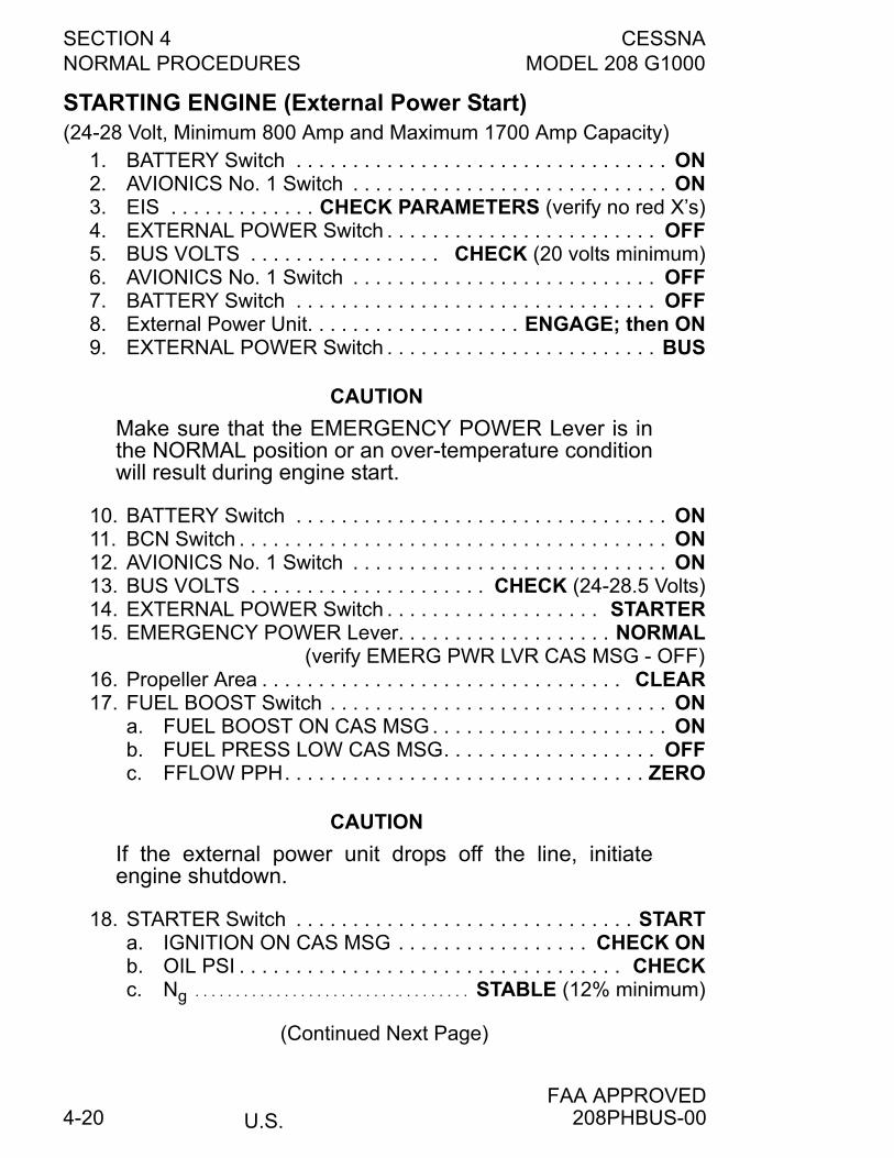
SECTION 4 CESSNANORMAL PROCEDURES MODEL 208 G1000
U.S.FAA APPROVED
4-20
STARTING ENGINE (External Power Start)(24-28 Volt, Minimum 800 Amp and Maximum 1700 Amp Capacity)
1. BATTERY Switch . . . . . . . . . . . . . . . . . . . . . . . . . . . . . . . . . ON2. AVIONICS No. 1 Switch . . . . . . . . . . . . . . . . . . . . . . . . . . . . ON3. EIS . . . . . . . . . . . . . CHECK PARAMETERS (verify no red X’s)4. EXTERNAL POWER Switch . . . . . . . . . . . . . . . . . . . . . . . . OFF5. BUS VOLTS . . . . . . . . . . . . . . . . . CHECK (20 volts minimum)6. AVIONICS No. 1 Switch . . . . . . . . . . . . . . . . . . . . . . . . . . . OFF7. BATTERY Switch . . . . . . . . . . . . . . . . . . . . . . . . . . . . . . . . OFF8. External Power Unit. . . . . . . . . . . . . . . . . . . ENGAGE; then ON9. EXTERNAL POWER Switch . . . . . . . . . . . . . . . . . . . . . . . . BUS
CAUTION
Make sure that the EMERGENCY POWER Lever is inthe NORMAL position or an over-temperature conditionwill result during engine start.
10. BATTERY Switch . . . . . . . . . . . . . . . . . . . . . . . . . . . . . . . . . ON11. BCN Switch . . . . . . . . . . . . . . . . . . . . . . . . . . . . . . . . . . . . . . ON12. AVIONICS No. 1 Switch . . . . . . . . . . . . . . . . . . . . . . . . . . . . ON13. BUS VOLTS . . . . . . . . . . . . . . . . . . . . . CHECK (24-28.5 Volts)14. EXTERNAL POWER Switch . . . . . . . . . . . . . . . . . . . STARTER15. EMERGENCY POWER Lever. . . . . . . . . . . . . . . . . . . NORMAL
(verify EMERG PWR LVR CAS MSG - OFF)16. Propeller Area . . . . . . . . . . . . . . . . . . . . . . . . . . . . . . . . CLEAR17. FUEL BOOST Switch . . . . . . . . . . . . . . . . . . . . . . . . . . . . . . ON
a. FUEL BOOST ON CAS MSG . . . . . . . . . . . . . . . . . . . . . ONb. FUEL PRESS LOW CAS MSG. . . . . . . . . . . . . . . . . . . OFFc. FFLOW PPH. . . . . . . . . . . . . . . . . . . . . . . . . . . . . . . . ZERO
CAUTION
If the external power unit drops off the line, initiateengine shutdown.
18. STARTER Switch . . . . . . . . . . . . . . . . . . . . . . . . . . . . . . STARTa. IGNITION ON CAS MSG . . . . . . . . . . . . . . . . . CHECK ONb. OIL PSI . . . . . . . . . . . . . . . . . . . . . . . . . . . . . . . . . . CHECKc. Ng . . . . . . . . . . . . . . . . . . . . . . . . . . . . . . . . . . STABLE (12% minimum)
(Continued Next Page)
208PHBUS-00
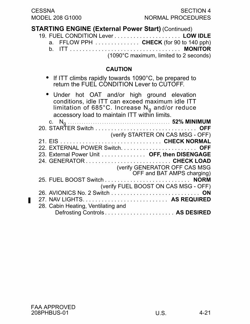
CESSNA SECTION 4MODEL 208 G1000 NORMAL PROCEDURES
U.S.FAA APPROVED
4-21
STARTING ENGINE (External Power Start) (Continued)19. FUEL CONDITION Lever . . . . . . . . . . . . . . . . . . . . . LOW IDLE
a. FFLOW PPH . . . . . . . . . . . . . . CHECK (for 90 to 140 pph)b. ITT . . . . . . . . . . . . . . . . . . . . . . . . . . . . . . . . . . . MONITOR
(1090°C maximum, limited to 2 seconds)
CAUTION
• If ITT climbs rapidly towards 1090°C, be prepared toreturn the FUEL CONDITION Lever to CUTOFF.
• Under hot OAT and/or high ground elevationconditions, idle ITT can exceed maximum idle ITTlimitation of 685°C. Increase Ng and/or reduceaccessory load to maintain ITT within limits.
c. Ng . . . . . . . . . . . . . . . . . . . . . . . . . . . . . . . . . . . . . . . . . . . . . 52% MINIMUM20. STARTER Switch . . . . . . . . . . . . . . . . . . . . . . . . . . . . . . . . OFF
(verify STARTER ON CAS MSG - OFF)21. EIS . . . . . . . . . . . . . . . . . . . . . . . . . . . . . . . . CHECK NORMAL22. EXTERNAL POWER Switch. . . . . . . . . . . . . . . . . . . . . . . . OFF23. External Power Unit . . . . . . . . . . . . . . OFF, then DISENGAGE24. GENERATOR . . . . . . . . . . . . . . . . . . . . . . . . . . . CHECK LOAD
(verify GENERATOR OFF CAS MSGOFF and BAT AMPS charging)
25. FUEL BOOST Switch . . . . . . . . . . . . . . . . . . . . . . . . . . . NORM(verify FUEL BOOST ON CAS MSG - OFF)
26. AVIONICS No. 2 Switch . . . . . . . . . . . . . . . . . . . . . . . . . . . . ON27. NAV LIGHTS. . . . . . . . . . . . . . . . . . . . . . . . . . . AS REQUIRED28. Cabin Heating, Ventilating and
Defrosting Controls . . . . . . . . . . . . . . . . . . . . . . AS DESIRED
208PHBUS-01
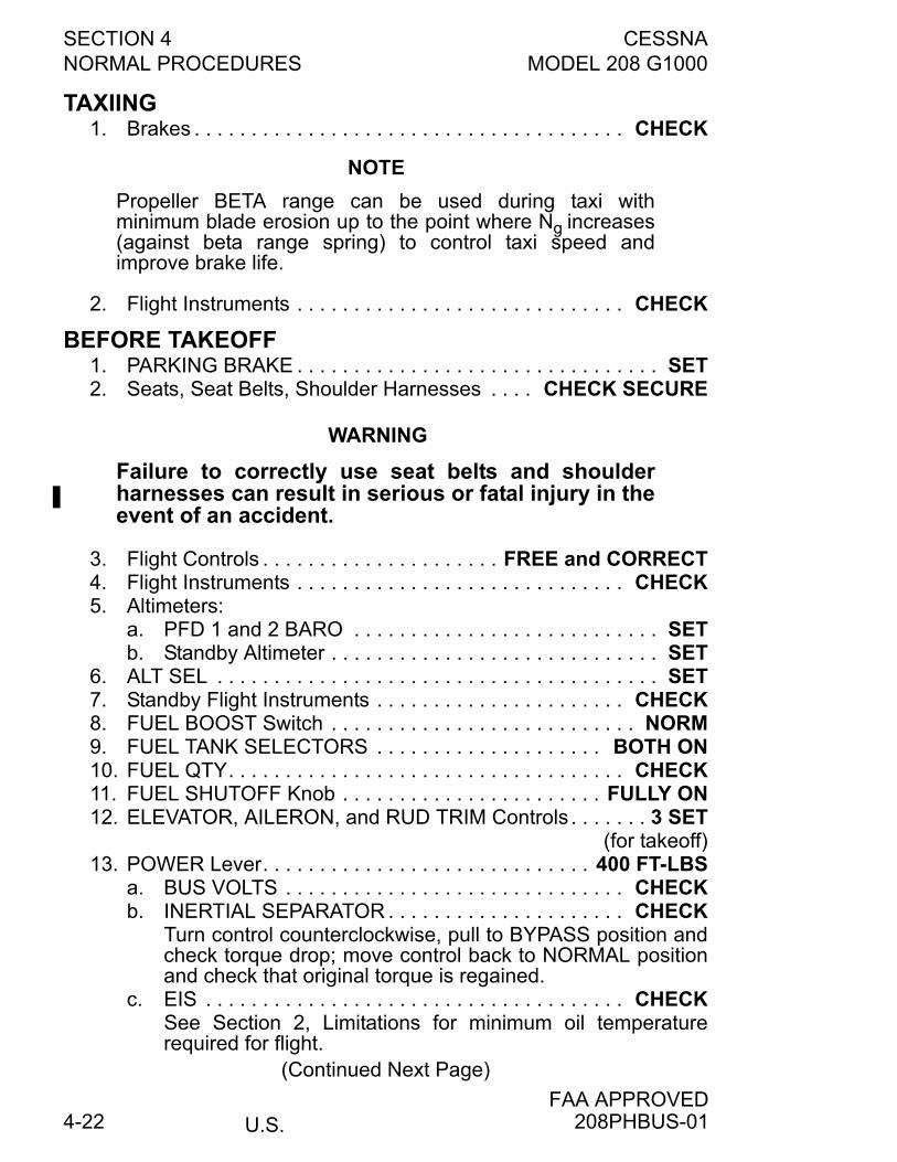
SECTION 4 CESSNANORMAL PROCEDURES MODEL 208 G1000
U.S.FAA APPROVED
4-22
TAXIING1. Brakes . . . . . . . . . . . . . . . . . . . . . . . . . . . . . . . . . . . . . . CHECK
NOTE
Propeller BETA range can be used during taxi withminimum blade erosion up to the point where Ng increases(against beta range spring) to control taxi speed andimprove brake life.
2. Flight Instruments . . . . . . . . . . . . . . . . . . . . . . . . . . . . . CHECK
BEFORE TAKEOFF1. PARKING BRAKE . . . . . . . . . . . . . . . . . . . . . . . . . . . . . . . . SET2. Seats, Seat Belts, Shoulder Harnesses . . . . CHECK SECURE
WARNING
Failure to correctly use seat belts and shoulderharnesses can result in serious or fatal injury in theevent of an accident.
3. Flight Controls . . . . . . . . . . . . . . . . . . . . . FREE and CORRECT4. Flight Instruments . . . . . . . . . . . . . . . . . . . . . . . . . . . . . CHECK5. Altimeters:
a. PFD 1 and 2 BARO . . . . . . . . . . . . . . . . . . . . . . . . . . . SETb. Standby Altimeter . . . . . . . . . . . . . . . . . . . . . . . . . . . . . SET
6. ALT SEL . . . . . . . . . . . . . . . . . . . . . . . . . . . . . . . . . . . . . . . SET7. Standby Flight Instruments . . . . . . . . . . . . . . . . . . . . . . CHECK8. FUEL BOOST Switch . . . . . . . . . . . . . . . . . . . . . . . . . . . NORM9. FUEL TANK SELECTORS . . . . . . . . . . . . . . . . . . . . BOTH ON10. FUEL QTY. . . . . . . . . . . . . . . . . . . . . . . . . . . . . . . . . . . CHECK11. FUEL SHUTOFF Knob . . . . . . . . . . . . . . . . . . . . . . . FULLY ON12. ELEVATOR, AILERON, and RUD TRIM Controls . . . . . . . 3 SET
(for takeoff)13. POWER Lever. . . . . . . . . . . . . . . . . . . . . . . . . . . . . 400 FT-LBS
a. BUS VOLTS . . . . . . . . . . . . . . . . . . . . . . . . . . . . . . CHECKb. INERTIAL SEPARATOR . . . . . . . . . . . . . . . . . . . . . CHECK
Turn control counterclockwise, pull to BYPASS position andcheck torque drop; move control back to NORMAL positionand check that original torque is regained.
c. EIS . . . . . . . . . . . . . . . . . . . . . . . . . . . . . . . . . . . . . CHECKSee Section 2, Limitations for minimum oil temperaturerequired for flight.
(Continued Next Page)
208PHBUS-01
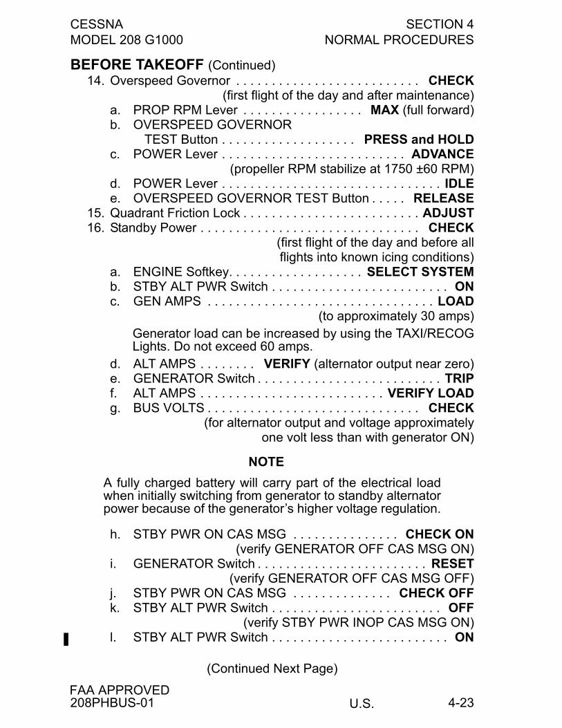
CESSNA SECTION 4MODEL 208 G1000 NORMAL PROCEDURES
U.S.FAA APPROVED
4-23
BEFORE TAKEOFF (Continued)14. Overspeed Governor . . . . . . . . . . . . . . . . . . . . . . . . . . CHECK
(first flight of the day and after maintenance)a. PROP RPM Lever . . . . . . . . . . . . . . . . . MAX (full forward)b. OVERSPEED GOVERNOR
TEST Button . . . . . . . . . . . . . . . . . . . PRESS and HOLDc. POWER Lever . . . . . . . . . . . . . . . . . . . . . . . . . . ADVANCE
(propeller RPM stabilize at 1750 ±60 RPM)d. POWER Lever . . . . . . . . . . . . . . . . . . . . . . . . . . . . . . . IDLEe. OVERSPEED GOVERNOR TEST Button . . . . . RELEASE
15. Quadrant Friction Lock . . . . . . . . . . . . . . . . . . . . . . . . . ADJUST16. Standby Power . . . . . . . . . . . . . . . . . . . . . . . . . . . . . . . CHECK
(first flight of the day and before allflights into known icing conditions)
a. ENGINE Softkey. . . . . . . . . . . . . . . . . . . SELECT SYSTEMb. STBY ALT PWR Switch . . . . . . . . . . . . . . . . . . . . . . . . . ONc. GEN AMPS . . . . . . . . . . . . . . . . . . . . . . . . . . . . . . . . LOAD
(to approximately 30 amps)Generator load can be increased by using the TAXI/RECOGLights. Do not exceed 60 amps.
d. ALT AMPS . . . . . . . . VERIFY (alternator output near zero)e. GENERATOR Switch . . . . . . . . . . . . . . . . . . . . . . . . . . TRIPf. ALT AMPS . . . . . . . . . . . . . . . . . . . . . . . . . . VERIFY LOADg. BUS VOLTS . . . . . . . . . . . . . . . . . . . . . . . . . . . . . . CHECK
(for alternator output and voltage approximatelyone volt less than with generator ON)
NOTE
A fully charged battery will carry part of the electrical loadwhen initially switching from generator to standby alternatorpower because of the generator’s higher voltage regulation.
h. STBY PWR ON CAS MSG . . . . . . . . . . . . . . . CHECK ON(verify GENERATOR OFF CAS MSG ON)
i. GENERATOR Switch . . . . . . . . . . . . . . . . . . . . . . . . RESET(verify GENERATOR OFF CAS MSG OFF)
j. STBY PWR ON CAS MSG . . . . . . . . . . . . . . CHECK OFFk. STBY ALT PWR Switch . . . . . . . . . . . . . . . . . . . . . . . . OFF
(verify STBY PWR INOP CAS MSG ON)l. STBY ALT PWR Switch . . . . . . . . . . . . . . . . . . . . . . . . . ON
(Continued Next Page)
208PHBUS-01
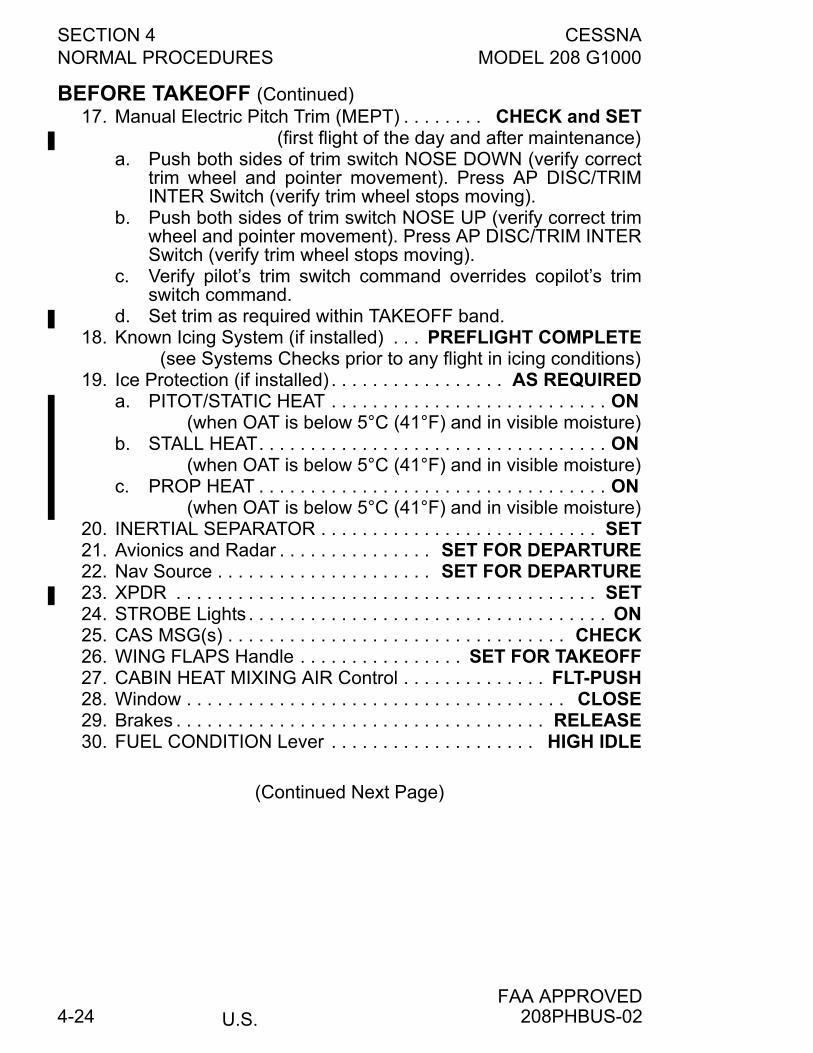
SECTION 4 CESSNANORMAL PROCEDURES MODEL 208 G1000
U.S.FAA APPROVED
4-24
BEFORE TAKEOFF (Continued)17. Manual Electric Pitch Trim (MEPT) . . . . . . . . CHECK and SET
(first flight of the day and after maintenance)a. Push both sides of trim switch NOSE DOWN (verify correct
trim wheel and pointer movement). Press AP DISC/TRIMINTER Switch (verify trim wheel stops moving).
b. Push both sides of trim switch NOSE UP (verify correct trimwheel and pointer movement). Press AP DISC/TRIM INTERSwitch (verify trim wheel stops moving).
c. Verify pilot’s trim switch command overrides copilot’s trimswitch command.
d. Set trim as required within TAKEOFF band.18. Known Icing System (if installed) . . . PREFLIGHT COMPLETE
(see Systems Checks prior to any flight in icing conditions)19. Ice Protection (if installed) . . . . . . . . . . . . . . . . . AS REQUIRED
a. PITOT/STATIC HEAT . . . . . . . . . . . . . . . . . . . . . . . . . . . ON (when OAT is below 5°C (41°F) and in visible moisture)
b. STALL HEAT. . . . . . . . . . . . . . . . . . . . . . . . . . . . . . . . . . ON (when OAT is below 5°C (41°F) and in visible moisture)
c. PROP HEAT . . . . . . . . . . . . . . . . . . . . . . . . . . . . . . . . . . ON (when OAT is below 5°C (41°F) and in visible moisture)
20. INERTIAL SEPARATOR . . . . . . . . . . . . . . . . . . . . . . . . . . . SET21. Avionics and Radar . . . . . . . . . . . . . . . SET FOR DEPARTURE22. Nav Source . . . . . . . . . . . . . . . . . . . . . SET FOR DEPARTURE23. XPDR . . . . . . . . . . . . . . . . . . . . . . . . . . . . . . . . . . . . . . . . . SET24. STROBE Lights . . . . . . . . . . . . . . . . . . . . . . . . . . . . . . . . . . . ON25. CAS MSG(s) . . . . . . . . . . . . . . . . . . . . . . . . . . . . . . . . . CHECK26. WING FLAPS Handle . . . . . . . . . . . . . . . . SET FOR TAKEOFF27. CABIN HEAT MIXING AIR Control . . . . . . . . . . . . . . FLT-PUSH28. Window . . . . . . . . . . . . . . . . . . . . . . . . . . . . . . . . . . . . . CLOSE29. Brakes . . . . . . . . . . . . . . . . . . . . . . . . . . . . . . . . . . . . RELEASE30. FUEL CONDITION Lever . . . . . . . . . . . . . . . . . . . . HIGH IDLE
(Continued Next Page)
208PHBUS-02
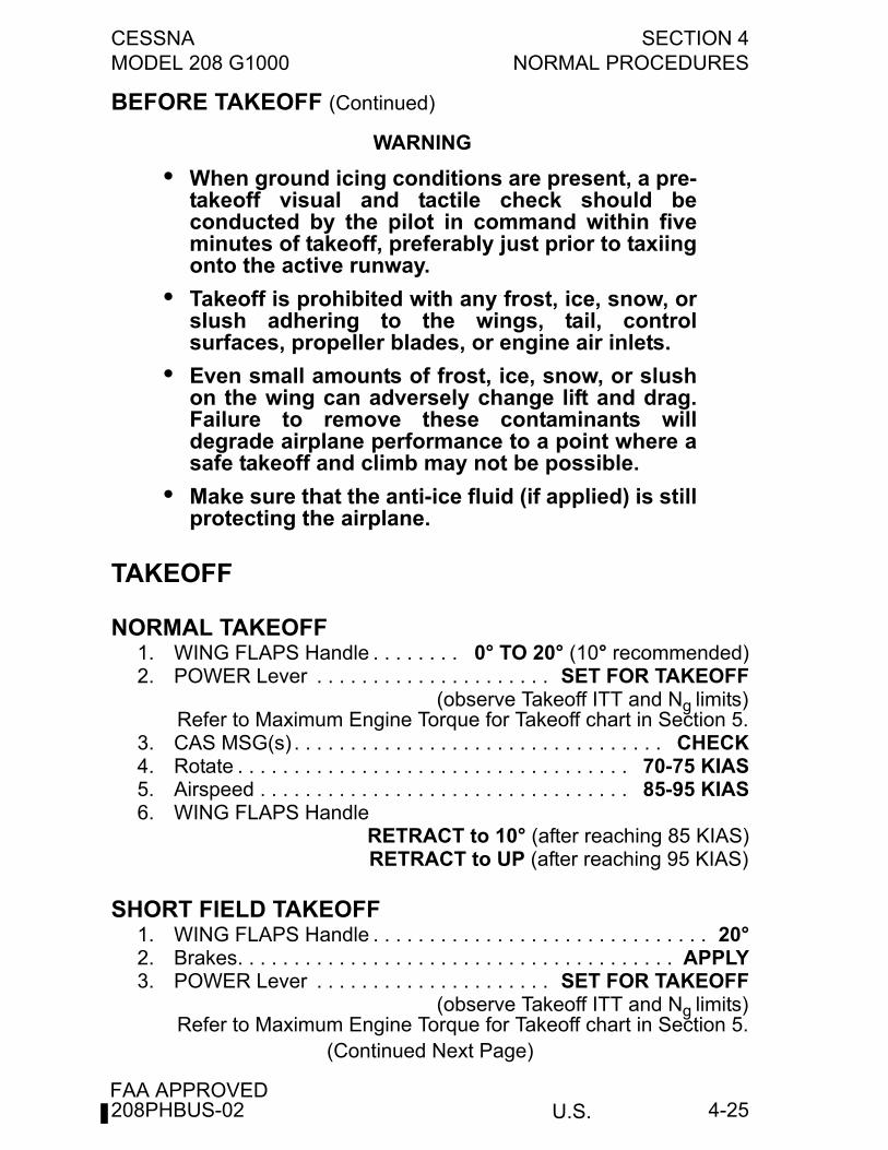
CESSNA SECTION 4MODEL 208 G1000 NORMAL PROCEDURES
U.S.FAA APPROVED
4-25
BEFORE TAKEOFF (Continued)
WARNING
• When ground icing conditions are present, a pre-takeoff visual and tactile check should beconducted by the pilot in command within fiveminutes of takeoff, preferably just prior to taxiingonto the active runway.
• Takeoff is prohibited with any frost, ice, snow, orslush adhering to the wings, tail, controlsurfaces, propeller blades, or engine air inlets.
• Even small amounts of frost, ice, snow, or slushon the wing can adversely change lift and drag.Failure to remove these contaminants willdegrade airplane performance to a point where asafe takeoff and climb may not be possible.
• Make sure that the anti-ice fluid (if applied) is stillprotecting the airplane.
TAKEOFF
NORMAL TAKEOFF1. WING FLAPS Handle . . . . . . . . 0° TO 20° (10° recommended)2. POWER Lever . . . . . . . . . . . . . . . . . . . . . SET FOR TAKEOFF
(observe Takeoff ITT and Ng limits)Refer to Maximum Engine Torque for Takeoff chart in Section 5.
3. CAS MSG(s) . . . . . . . . . . . . . . . . . . . . . . . . . . . . . . . . . CHECK4. Rotate . . . . . . . . . . . . . . . . . . . . . . . . . . . . . . . . . . . 70-75 KIAS5. Airspeed . . . . . . . . . . . . . . . . . . . . . . . . . . . . . . . . . 85-95 KIAS6. WING FLAPS Handle
RETRACT to 10° (after reaching 85 KIAS)RETRACT to UP (after reaching 95 KIAS)
SHORT FIELD TAKEOFF1. WING FLAPS Handle . . . . . . . . . . . . . . . . . . . . . . . . . . . . . . 20°2. Brakes. . . . . . . . . . . . . . . . . . . . . . . . . . . . . . . . . . . . . . . APPLY3. POWER Lever . . . . . . . . . . . . . . . . . . . . . SET FOR TAKEOFF
(observe Takeoff ITT and Ng limits)Refer to Maximum Engine Torque for Takeoff chart in Section 5.
(Continued Next Page)
208PHBUS-02
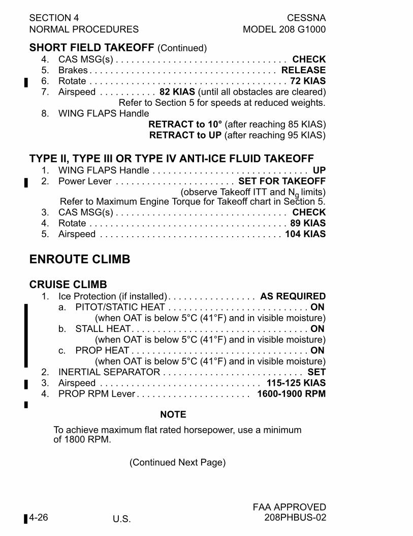
SECTION 4 CESSNANORMAL PROCEDURES MODEL 208 G1000
U.S.FAA APPROVED
4-26
SHORT FIELD TAKEOFF (Continued)4. CAS MSG(s) . . . . . . . . . . . . . . . . . . . . . . . . . . . . . . . . . CHECK5. Brakes . . . . . . . . . . . . . . . . . . . . . . . . . . . . . . . . . . . . RELEASE6. Rotate . . . . . . . . . . . . . . . . . . . . . . . . . . . . . . . . . . . . . . 72 KIAS7. Airspeed . . . . . . . . . . . 82 KIAS (until all obstacles are cleared)
Refer to Section 5 for speeds at reduced weights.8. WING FLAPS Handle
RETRACT to 10° (after reaching 85 KIAS)RETRACT to UP (after reaching 95 KIAS)
TYPE II, TYPE III OR TYPE IV ANTI-ICE FLUID TAKEOFF1. WING FLAPS Handle . . . . . . . . . . . . . . . . . . . . . . . . . . . . . . UP2. Power Lever . . . . . . . . . . . . . . . . . . . . . . . SET FOR TAKEOFF
(observe Takeoff ITT and Ng limits)Refer to Maximum Engine Torque for Takeoff chart in Section 5.
3. CAS MSG(s) . . . . . . . . . . . . . . . . . . . . . . . . . . . . . . . . . CHECK4. Rotate . . . . . . . . . . . . . . . . . . . . . . . . . . . . . . . . . . . . . . 89 KIAS5. Airspeed . . . . . . . . . . . . . . . . . . . . . . . . . . . . . . . . . . . 104 KIAS
ENROUTE CLIMB
CRUISE CLIMB1. Ice Protection (if installed) . . . . . . . . . . . . . . . . . AS REQUIRED
a. PITOT/STATIC HEAT . . . . . . . . . . . . . . . . . . . . . . . . . . . ON (when OAT is below 5°C (41°F) and in visible moisture)
b. STALL HEAT. . . . . . . . . . . . . . . . . . . . . . . . . . . . . . . . . . ON (when OAT is below 5°C (41°F) and in visible moisture)
c. PROP HEAT . . . . . . . . . . . . . . . . . . . . . . . . . . . . . . . . . . ON (when OAT is below 5°C (41°F) and in visible moisture)
2. INERTIAL SEPARATOR . . . . . . . . . . . . . . . . . . . . . . . . . . . SET3. Airspeed . . . . . . . . . . . . . . . . . . . . . . . . . . . . . . . 115-125 KIAS4. PROP RPM Lever . . . . . . . . . . . . . . . . . . . . . . 1600-1900 RPM
NOTE
To achieve maximum flat rated horsepower, use a minimumof 1800 RPM.
(Continued Next Page)
208PHBUS-02
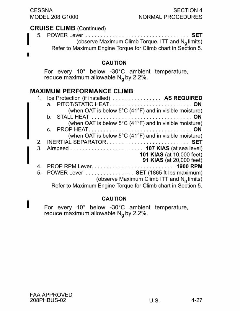
CESSNA SECTION 4MODEL 208 G1000 NORMAL PROCEDURES
U.S.FAA APPROVED
4-27
CRUISE CLIMB (Continued)5. POWER Lever . . . . . . . . . . . . . . . . . . . . . . . . . . . . . . . . . . SET
(observe Maximum Climb Torque, ITT and Ng limits)Refer to Maximum Engine Torque for Climb chart in Section 5.
CAUTION
For every 10° below -30°C ambient temperature,reduce maximum allowable Ng by 2.2%.
MAXIMUM PERFORMANCE CLIMB1. Ice Protection (if installed) . . . . . . . . . . . . . . . . AS REQUIRED
a. PITOT/STATIC HEAT . . . . . . . . . . . . . . . . . . . . . . . . . . . ON (when OAT is below 5°C (41°F) and in visible moisture)
b. STALL HEAT . . . . . . . . . . . . . . . . . . . . . . . . . . . . . . . . . ON (when OAT is below 5°C (41°F) and in visible moisture)
c. PROP HEAT. . . . . . . . . . . . . . . . . . . . . . . . . . . . . . . . . . ON (when OAT is below 5°C (41°F) and in visible moisture)
2. INERTIAL SEPARATOR . . . . . . . . . . . . . . . . . . . . . . . . . . . SET3. Airspeed . . . . . . . . . . . . . . . . . . . . . . . . 107 KIAS (at sea level)
101 KIAS (at 10,000 feet)91 KIAS (at 20,000 feet)
4. PROP RPM Lever. . . . . . . . . . . . . . . . . . . . . . . . . . . 1900 RPM5. POWER Lever . . . . . . . . . . . . . . . . SET (1865 ft-lbs maximum)
(observe Maximum Climb ITT and Ng limits)Refer to Maximum Engine Torque for Climb chart in Section 5.
CAUTION
For every 10° below -30°C ambient temperature,reduce maximum allowable Ng by 2.2%.
208PHBUS-02
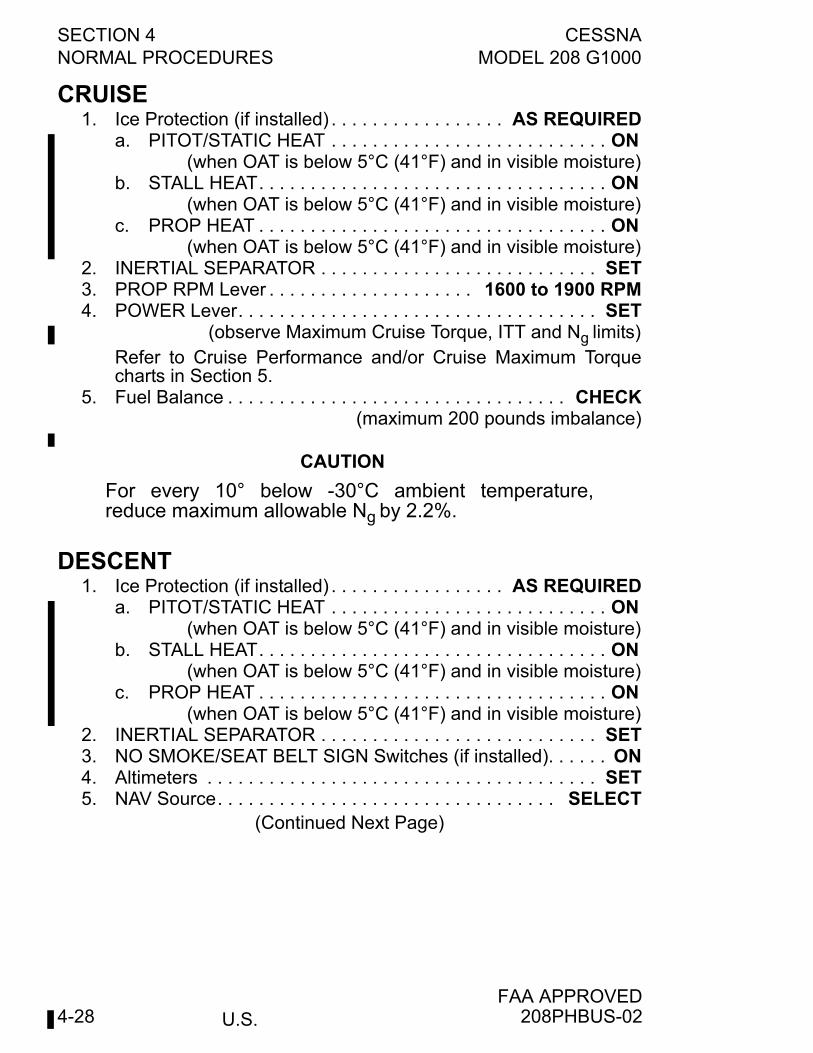
SECTION 4 CESSNANORMAL PROCEDURES MODEL 208 G1000
U.S.FAA APPROVED
4-28
CRUISE1. Ice Protection (if installed) . . . . . . . . . . . . . . . . . AS REQUIRED
a. PITOT/STATIC HEAT . . . . . . . . . . . . . . . . . . . . . . . . . . . ON (when OAT is below 5°C (41°F) and in visible moisture)
b. STALL HEAT. . . . . . . . . . . . . . . . . . . . . . . . . . . . . . . . . . ON (when OAT is below 5°C (41°F) and in visible moisture)
c. PROP HEAT . . . . . . . . . . . . . . . . . . . . . . . . . . . . . . . . . . ON (when OAT is below 5°C (41°F) and in visible moisture)
2. INERTIAL SEPARATOR . . . . . . . . . . . . . . . . . . . . . . . . . . . SET3. PROP RPM Lever . . . . . . . . . . . . . . . . . . . . 1600 to 1900 RPM4. POWER Lever. . . . . . . . . . . . . . . . . . . . . . . . . . . . . . . . . . . SET
(observe Maximum Cruise Torque, ITT and Ng limits)Refer to Cruise Performance and/or Cruise Maximum Torquecharts in Section 5.
5. Fuel Balance . . . . . . . . . . . . . . . . . . . . . . . . . . . . . . . . . CHECK(maximum 200 pounds imbalance)
CAUTION
For every 10° below -30°C ambient temperature,reduce maximum allowable Ng by 2.2%.
DESCENT1. Ice Protection (if installed) . . . . . . . . . . . . . . . . . AS REQUIRED
a. PITOT/STATIC HEAT . . . . . . . . . . . . . . . . . . . . . . . . . . . ON (when OAT is below 5°C (41°F) and in visible moisture)
b. STALL HEAT. . . . . . . . . . . . . . . . . . . . . . . . . . . . . . . . . . ON (when OAT is below 5°C (41°F) and in visible moisture)
c. PROP HEAT . . . . . . . . . . . . . . . . . . . . . . . . . . . . . . . . . . ON (when OAT is below 5°C (41°F) and in visible moisture)
2. INERTIAL SEPARATOR . . . . . . . . . . . . . . . . . . . . . . . . . . . SET3. NO SMOKE/SEAT BELT SIGN Switches (if installed). . . . . . ON4. Altimeters . . . . . . . . . . . . . . . . . . . . . . . . . . . . . . . . . . . . . . SET5. NAV Source. . . . . . . . . . . . . . . . . . . . . . . . . . . . . . . . . SELECT
(Continued Next Page)
208PHBUS-02
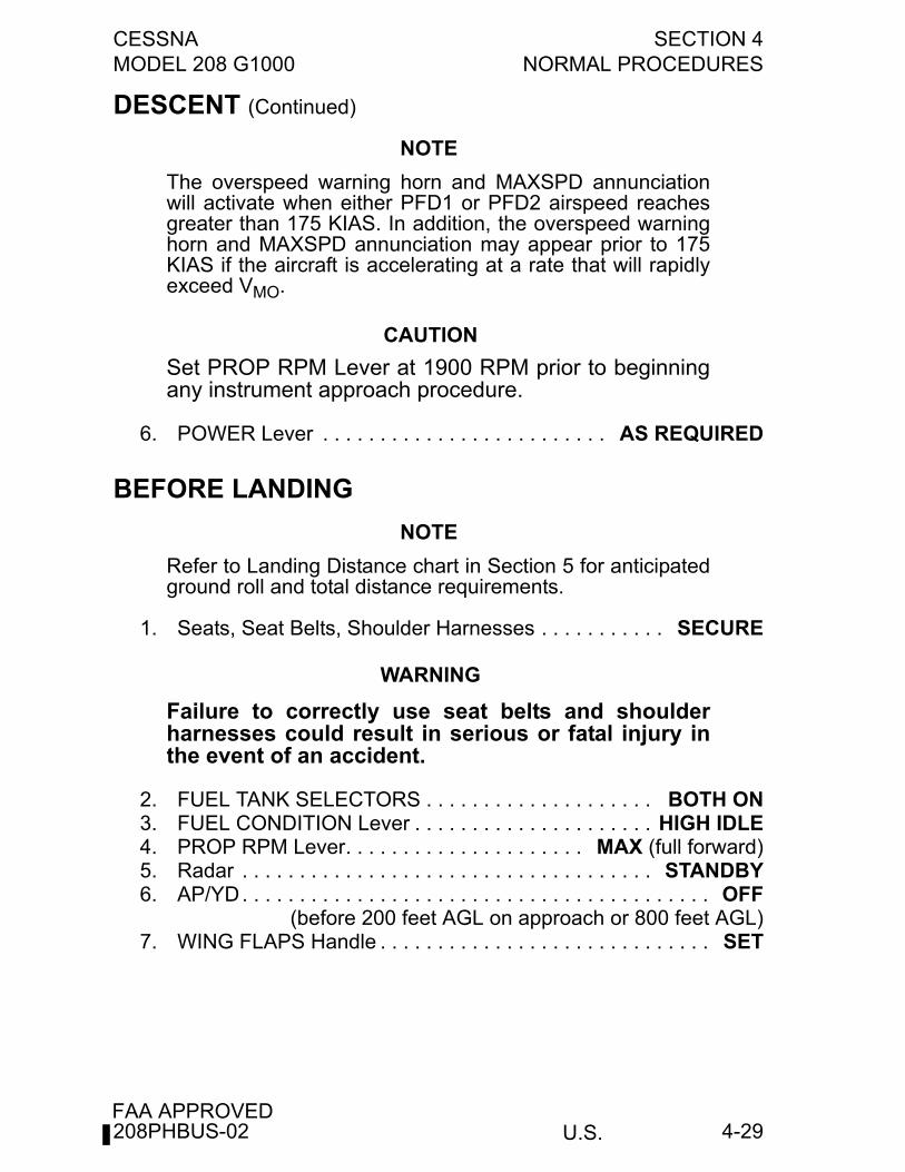
CESSNA SECTION 4MODEL 208 G1000 NORMAL PROCEDURES
U.S.FAA APPROVED
4-29
DESCENT (Continued)
NOTE
The overspeed warning horn and MAXSPD annunciationwill activate when either PFD1 or PFD2 airspeed reachesgreater than 175 KIAS. In addition, the overspeed warninghorn and MAXSPD annunciation may appear prior to 175KIAS if the aircraft is accelerating at a rate that will rapidlyexceed VMO.
CAUTION
Set PROP RPM Lever at 1900 RPM prior to beginningany instrument approach procedure.
6. POWER Lever . . . . . . . . . . . . . . . . . . . . . . . . . AS REQUIRED
BEFORE LANDING
NOTE
Refer to Landing Distance chart in Section 5 for anticipatedground roll and total distance requirements.
1. Seats, Seat Belts, Shoulder Harnesses . . . . . . . . . . . SECURE
WARNING
Failure to correctly use seat belts and shoulderharnesses could result in serious or fatal injury inthe event of an accident.
2. FUEL TANK SELECTORS . . . . . . . . . . . . . . . . . . . . BOTH ON3. FUEL CONDITION Lever . . . . . . . . . . . . . . . . . . . . . HIGH IDLE4. PROP RPM Lever. . . . . . . . . . . . . . . . . . . . . MAX (full forward)5. Radar . . . . . . . . . . . . . . . . . . . . . . . . . . . . . . . . . . . . STANDBY6. AP/YD. . . . . . . . . . . . . . . . . . . . . . . . . . . . . . . . . . . . . . . . . OFF
(before 200 feet AGL on approach or 800 feet AGL)7. WING FLAPS Handle . . . . . . . . . . . . . . . . . . . . . . . . . . . . . SET
208PHBUS-02
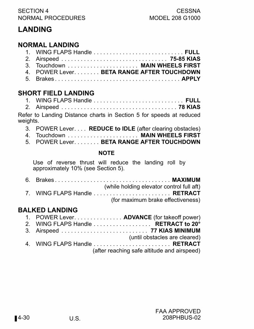
SECTION 4 CESSNANORMAL PROCEDURES MODEL 208 G1000
U.S.FAA APPROVED
4-30
LANDING
NORMAL LANDING1. WING FLAPS Handle . . . . . . . . . . . . . . . . . . . . . . . . . . . . FULL 2. Airspeed . . . . . . . . . . . . . . . . . . . . . . . . . . . . . . . . . 75-85 KIAS3. Touchdown . . . . . . . . . . . . . . . . . . . . . . MAIN WHEELS FIRST4. POWER Lever. . . . . . . . BETA RANGE AFTER TOUCHDOWN5. Brakes . . . . . . . . . . . . . . . . . . . . . . . . . . . . . . . . . . . . . . . APPLY
SHORT FIELD LANDING1. WING FLAPS Handle . . . . . . . . . . . . . . . . . . . . . . . . . . . . FULL2. Airspeed . . . . . . . . . . . . . . . . . . . . . . . . . . . . . . . . . . . . 78 KIAS
Refer to Landing Distance charts in Section 5 for speeds at reducedweights.
3. POWER Lever. . . . REDUCE to IDLE (after clearing obstacles)4. Touchdown . . . . . . . . . . . . . . . . . . . . . . MAIN WHEELS FIRST5. POWER Lever. . . . . . . . BETA RANGE AFTER TOUCHDOWN
NOTE
Use of reverse thrust will reduce the landing roll byapproximately 10% (see Section 5).
6. Brakes . . . . . . . . . . . . . . . . . . . . . . . . . . . . . . . . . . . . MAXIMUM(while holding elevator control full aft)
7. WING FLAPS Handle . . . . . . . . . . . . . . . . . . . . . . . . RETRACT(for maximum brake effectiveness)
BALKED LANDING1. POWER Lever. . . . . . . . . . . . . . . ADVANCE (for takeoff power)2. WING FLAPS Handle . . . . . . . . . . . . . . . . . . RETRACT to 20°3. Airspeed . . . . . . . . . . . . . . . . . . . . . . . . . . . 77 KIAS MINIMUM
(until obstacles are cleared)4. WING FLAPS Handle . . . . . . . . . . . . . . . . . . . . . . . . RETRACT
(after reaching safe altitude and airspeed)
208PHBUS-02
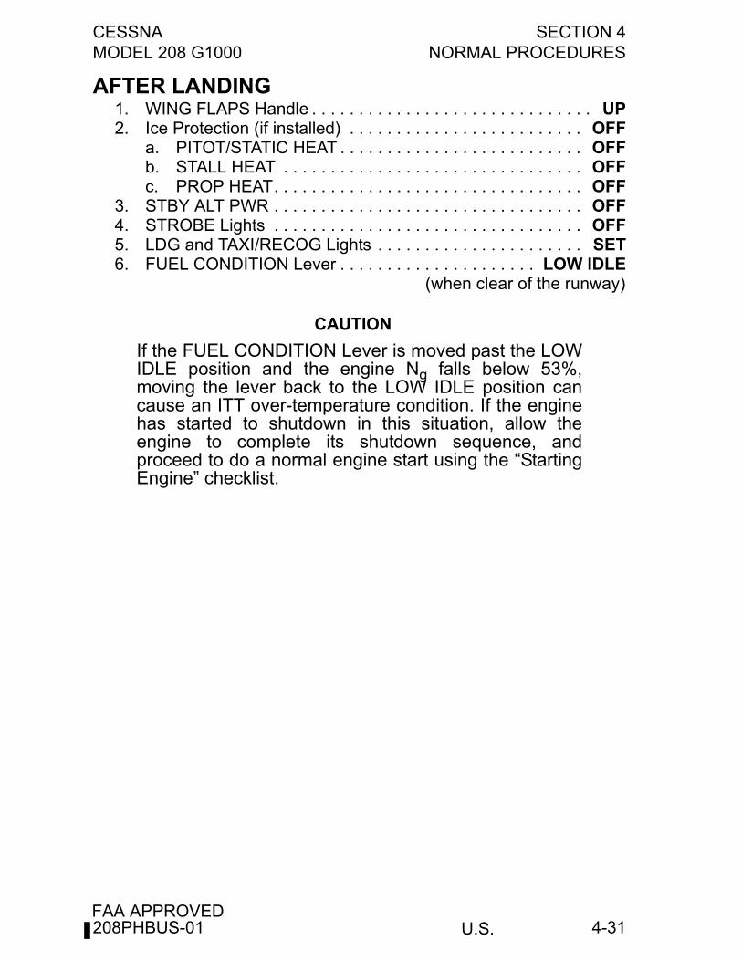
CESSNA SECTION 4MODEL 208 G1000 NORMAL PROCEDURES
U.S.FAA APPROVED
4-31
AFTER LANDING1. WING FLAPS Handle . . . . . . . . . . . . . . . . . . . . . . . . . . . . . . UP2. Ice Protection (if installed) . . . . . . . . . . . . . . . . . . . . . . . . . OFF
a. PITOT/STATIC HEAT . . . . . . . . . . . . . . . . . . . . . . . . . . OFFb. STALL HEAT . . . . . . . . . . . . . . . . . . . . . . . . . . . . . . . . OFFc. PROP HEAT. . . . . . . . . . . . . . . . . . . . . . . . . . . . . . . . . OFF
3. STBY ALT PWR . . . . . . . . . . . . . . . . . . . . . . . . . . . . . . . . . OFF4. STROBE Lights . . . . . . . . . . . . . . . . . . . . . . . . . . . . . . . . . OFF5. LDG and TAXI/RECOG Lights . . . . . . . . . . . . . . . . . . . . . . SET6. FUEL CONDITION Lever . . . . . . . . . . . . . . . . . . . . . LOW IDLE
(when clear of the runway)
CAUTION
If the FUEL CONDITION Lever is moved past the LOWIDLE position and the engine Ng falls below 53%,moving the lever back to the LOW IDLE position cancause an ITT over-temperature condition. If the enginehas started to shutdown in this situation, allow theengine to complete its shutdown sequence, andproceed to do a normal engine start using the “StartingEngine” checklist.
208PHBUS-01
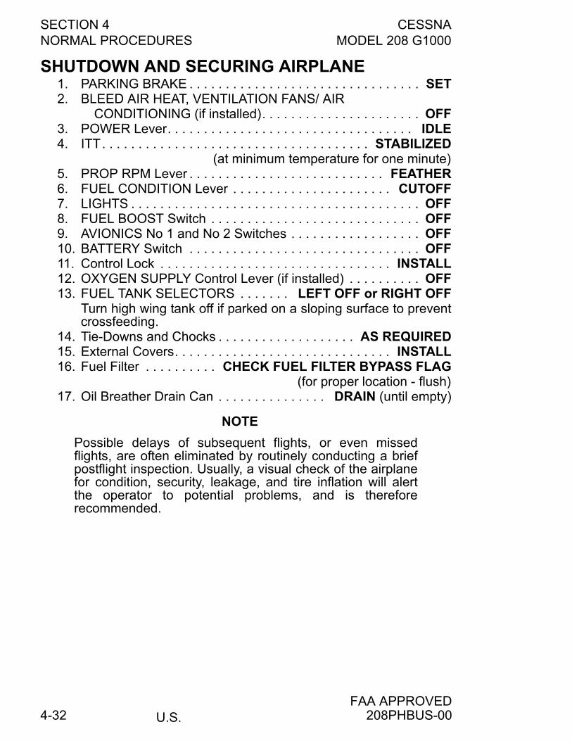
SECTION 4 CESSNANORMAL PROCEDURES MODEL 208 G1000
U.S.FAA APPROVED
4-32
SHUTDOWN AND SECURING AIRPLANE1. PARKING BRAKE . . . . . . . . . . . . . . . . . . . . . . . . . . . . . . . . SET2. BLEED AIR HEAT, VENTILATION FANS/ AIR
CONDITIONING (if installed). . . . . . . . . . . . . . . . . . . . . . OFF3. POWER Lever. . . . . . . . . . . . . . . . . . . . . . . . . . . . . . . . . . IDLE4. ITT. . . . . . . . . . . . . . . . . . . . . . . . . . . . . . . . . . . . . STABILIZED
(at minimum temperature for one minute)5. PROP RPM Lever . . . . . . . . . . . . . . . . . . . . . . . . . . . FEATHER6. FUEL CONDITION Lever . . . . . . . . . . . . . . . . . . . . . . CUTOFF7. LIGHTS . . . . . . . . . . . . . . . . . . . . . . . . . . . . . . . . . . . . . . . . OFF8. FUEL BOOST Switch . . . . . . . . . . . . . . . . . . . . . . . . . . . . . OFF9. AVIONICS No 1 and No 2 Switches . . . . . . . . . . . . . . . . . . OFF10. BATTERY Switch . . . . . . . . . . . . . . . . . . . . . . . . . . . . . . . . OFF11. Control Lock . . . . . . . . . . . . . . . . . . . . . . . . . . . . . . . . INSTALL12. OXYGEN SUPPLY Control Lever (if installed) . . . . . . . . . . OFF13. FUEL TANK SELECTORS . . . . . . . LEFT OFF or RIGHT OFF
Turn high wing tank off if parked on a sloping surface to preventcrossfeeding.
14. Tie-Downs and Chocks . . . . . . . . . . . . . . . . . . . AS REQUIRED15. External Covers. . . . . . . . . . . . . . . . . . . . . . . . . . . . . . INSTALL16. Fuel Filter . . . . . . . . . . CHECK FUEL FILTER BYPASS FLAG
(for proper location - flush)17. Oil Breather Drain Can . . . . . . . . . . . . . . . DRAIN (until empty)
NOTE
Possible delays of subsequent flights, or even missedflights, are often eliminated by routinely conducting a briefpostflight inspection. Usually, a visual check of the airplanefor condition, security, leakage, and tire inflation will alertthe operator to potential problems, and is thereforerecommended.
208PHBUS-00
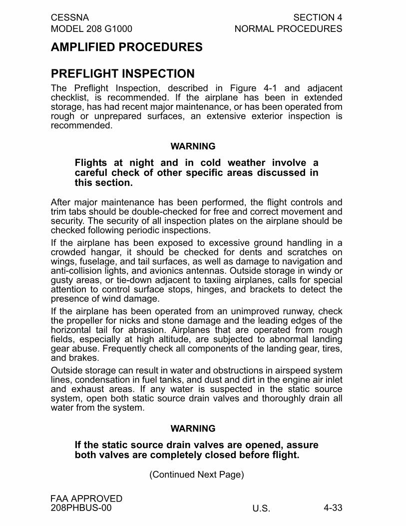
CESSNA SECTION 4MODEL 208 G1000 NORMAL PROCEDURES
U.S.FAA APPROVED
4-33
AMPLIFIED PROCEDURES
PREFLIGHT INSPECTIONThe Preflight Inspection, described in Figure 4-1 and adjacentchecklist, is recommended. If the airplane has been in extendedstorage, has had recent major maintenance, or has been operated fromrough or unprepared surfaces, an extensive exterior inspection isrecommended.
WARNING
Flights at night and in cold weather involve acareful check of other specific areas discussed inthis section.
After major maintenance has been performed, the flight controls andtrim tabs should be double-checked for free and correct movement andsecurity. The security of all inspection plates on the airplane should bechecked following periodic inspections.If the airplane has been exposed to excessive ground handling in acrowded hangar, it should be checked for dents and scratches onwings, fuselage, and tail surfaces, as well as damage to navigation andanti-collision lights, and avionics antennas. Outside storage in windy orgusty areas, or tie-down adjacent to taxiing airplanes, calls for specialattention to control surface stops, hinges, and brackets to detect thepresence of wind damage.If the airplane has been operated from an unimproved runway, checkthe propeller for nicks and stone damage and the leading edges of thehorizontal tail for abrasion. Airplanes that are operated from roughfields, especially at high altitude, are subjected to abnormal landinggear abuse. Frequently check all components of the landing gear, tires,and brakes.Outside storage can result in water and obstructions in airspeed systemlines, condensation in fuel tanks, and dust and dirt in the engine air inletand exhaust areas. If any water is suspected in the static sourcesystem, open both static source drain valves and thoroughly drain allwater from the system.
WARNING
If the static source drain valves are opened, assureboth valves are completely closed before flight.
(Continued Next Page)
208PHBUS-00
SECTION 4 CESSNANORMAL PROCEDURES MODEL 208 G1000
U.S.FAA APPROVED
4-34
PREFLIGHT INSPECTION (Continued)
If any water is detected in the fuel system, the inboard fuel tank sumpand external sump quick-drain valves, fuel reservoir quick-drain valve,and fuel filter quick-drain valve should all be thoroughly drained untilthere is no evidence of water or sediment contamination. If the airplaneis parked with one wing low on a sloping ramp, draining of the outboardfuel tank sump quick-drain valves (if installed) is also recommended.Prolonged storage of the airplane will result in a water buildup in thefuel which "leaches out" the fuel additive. An indication of this is whenan excessive amount of water accumulates in the fuel tank sumps.Refer to Section 8 for fuel additive servicing.To prevent loss of fuel in flight, make sure the fuel tank filler caps aretightly sealed after any fuel system check or servicing. Fuel systemvents should also be inspected for obstructions, ice or water, especiallyafter exposure to cold, wet weather.The interior inspection will vary according to the planned flight and theoptional equipment installed. Prior to high-altitude flights, it is importantto check the condition and quantity of oxygen face masks and hoseassemblies. The oxygen supply system (if installed) should befunctionally checked to ensure that it is in working order and that anadequate supply of oxygen is available.
BEFORE STARTING ENGINE
WARNING
• It is the responsibility of the pilot in command tomake sure that the airplane is correctly loadedwithin the weight and center of gravity limitsprior to takeoff.
• Failure to correctly use seat belts and shoulderharnesses could result in serious or fatal injuryin the event of an accident.
(Continued Next Page)
208PHBUS-00
CESSNA SECTION 4MODEL 208 G1000 NORMAL PROCEDURES
U.S.FAA APPROVED
4-35
BEFORE STARTING ENGINE (Continued)
The Before Starting Engine checklist procedures should be followedclosely to assure a satisfactory engine start. Most of the checklist itemsare self-explanatory. Those items that may require further explanationare noted in the following discussion.When setting electrical switches prior to engine start, only those lightingswitches that are necessary for a night-time engine start should beturned on. All other switches, including exterior lights, anti-ice, deice,ventilation fans/ air conditioning (if installed) switches, should be turnedoff. The BLEED AIR HEAT Switch should be off to prevent excessivecompressor bleed during the engine start. Also, the standby powerswitch should be off during engine starts.
CAUTION
Leaving the BLEED AIR HEAT Switch ON can result ina hot start or abnormal acceleration to idle.
The generator switch is spring-loaded to the ON position. When thestarter switch is placed in the START or MOTOR position, the generatorcontrol unit (GCU) opens the generator contactor. When the starterswitch is returned to the OFF position after an engine start, the GCUcloses the generator contactor, thereby placing the generator on theline.The IGNITION Switch is left in the NORM position for engine startingwith the starter motor (non-windmilling start). In this position, theigniters are energized when the starter switch is placed in the STARTposition. Ignition is automatically terminated when the starter switch isturned OFF.
CAUTION
It is especially important to verify that theEMERGENCY POWER Lever is in the NORMALposition (aft of the IDLE gate) during engine starts. Withthe lever forward of this gate, excessive quantities offuel will be discharged through the fuel nozzles whenthe FUEL CONDITION Lever is moved to the LOWIDLE position and a hot start will result.
(Continued Next Page)
208PHBUS-00
SECTION 4 CESSNANORMAL PROCEDURES MODEL 208 G1000
U.S.FAA APPROVED
4-36
BEFORE STARTING ENGINE (Continued)
Before starting the engine, the POWER Lever is placed at the IDLEposition (against the BETA gate), the propeller control lever is moved tothe MAX RPM position (full forward), and the FUEL CONDITION Leveris stowed in the CUTOFF position.
CAUTION
The propeller reversing linkage can be damaged if thePOWER Lever is moved aft of the IDLE position whenthe engine is not running and the propeller is feathered.
STARTING ENGINEThe Starting Engine checklist procedures should be followed closely toassure a satisfactory engine start. With the FUEL CONDITION Lever inthe CUTOFF position, move the starter switch to the START position;verify that the STARTER ON and IGNITION ON CAS MSG(s) aredisplayed. Next, check for a positive indication of engine oil pressure.After Ng stabilizes (minimum of 12%), move the FUEL CONDITIONLever to the LOW IDLE position and verify fuel flow in the generalrange of 90 to 140 pph. After the engine "lights off" and duringacceleration to idle (approximately 52% Ng), monitor ITT and Ng.Maximum ITT during engine start is 1090°C, limited to 2 seconds.Typically, the ITT during start is well below this maximum value. Afterthe engine has stabilized at idle, the STARTER ON CAS MSG shouldbe OFF. If this CAS MSG remains ON, it indicates the starter has notbeen automatically disengaged during the engine starting sequencedue to a failed speed sensor.
CAUTION
If no ITT rise is observed within 10 seconds aftermoving the FUEL CONDITION Lever to the LOW IDLEposition, or ITT rapidly approaches 1090°C, move theFUEL CONDITION Lever to CUTOFF and perform theEngine Clearing Procedure in this section.
(Continued Next Page)
208PHBUS-00
CESSNA SECTION 4MODEL 208 G1000 NORMAL PROCEDURES
U.S.FAA APPROVED
4-37
STARTING ENGINE (Continued)
After the engine reaches stabilized idle (52% Ng or above), return thestarter switch to the OFF position. With a cold engine or after making abattery start (high initial generator load into battery), it may benecessary to advance the POWER Lever slightly ahead of the idledetent to maintain a minimum idle of 52% Ng. To assure maintainingthe minimum Ng and ITT within limits, advance the POWER Lever toobtain approximately 55% Ng before turning the starter switch OFF (thegenerator contactor closes when the starter switch is turned OFF).
CAUTION
Under hot OAT and/or high ground elevation conditions,idle ITT can exceed maximum idle ITT limitation of685°C. Increase Ng and/or reduce accessory load tomaintain ITT within limits.
NOTE
If the STARTER ENERGIZED CAS MSG fails to go outafter the starter switch has been moved to the OFFposition, the start contactor can be closed and thegenerator will not function. Perform an engine shutdown.
Engine starts can be made with airplane battery power or with anexternal power unit (EPU). However, it is recommended that an EPU beused when the ambient air temperature is less than -18°C (0°F). Referto Cold Weather Operation in this section when ambient temperature isbelow -18°C (0°F).
CAUTION
• In the event the external power unit drops off the lineduring engine start, a loss of electrical power to thestarter will result which could cause a hot start.Should a loss of external power occur, immediatelyplace the FUEL CONDITION Lever to CUTOFF,monitor ITT, and make sure the engine is shuttingdown. Turn the external power switch off and placethe starter switch to the MOTOR position to aid inreducing ITT if necessary.
(Continued Next Page)
208PHBUS-00
SECTION 4 CESSNANORMAL PROCEDURES MODEL 208 G1000
U.S.FAA APPROVED
4-38
STARTING ENGINE (Continued)
• When an external power unit is used, make sure theunit is negatively grounded and regulated to 28 voltsDC with a capability of providing a minimum of 800amperes during the starting cycle. External powerunits with output exceeding 1700 amperes shall notbe used.
Before engine starting with the airplane battery, check the BUS VOLTSfor a minimum of 24 volts. Monitor ITT during each engine start toguard against a hot start. The operator must be ready to immediatelyabort the start if ITT exceeds 1090°C or is rapidly approaching this limit.Usually, hot starts are not a problem if the normal starting proceduresare followed.
CAUTION
A minimum battery voltage of 24 volts is not always anindication that the battery is near full charge or in goodcondition. Therefore, if gas generator acceleration inthe initial part of the start is less than normallyobserved, return the FUEL CONDITION Lever toCUTOFF and discontinue the start. Recharge thebattery or use an external power unit before attemptinganother start.
If the starter accelerates the gas generator rapidly above 20%, suspectgear train decouple. Do not continue start. Rapid acceleration through35% Ng suggests a start on the secondary nozzles. Anticipate a hotstart.After an aborted start for whatever reason, it is essential before the nextstart attempt to allow adequate time to drain off unburned fuel. Failureto drain all residual fuel from the engine could lead to a hot start, a hotstreak leading to hot section damage, or the torching of burning fuelfrom engine exhaust on the next successful ignition.A dry motoring, within starter limitations after confirming that all fueldrainage has stopped, will ensure that no fuel is trapped before thenext start.
208PHBUS-00
CESSNA SECTION 4MODEL 208 G1000 NORMAL PROCEDURES
U.S.FAA APPROVED
4-39
ENGINE CLEARING PROCEDURES (DRYMOTORING RUN)The following procedure is used to clear an engine at any time when itis deemed necessary to remove internally trapped fuel and vapor, or ifthere is evidence of a fire within the engine. Air passing through theengine serves to purge fuel, vapor, or fire from the combustion section,gas generator turbine, power turbine, and exhaust system.
1. FUEL CONDITION Lever . . . . . . . . . . . . . . . . . . . . . . . CUTOFF2. IGNITION Switch . . . . . . . . . . . . . . . . . . . . . . . . . . . . . . NORM3. BATTERY Switch . . . . . . . . . . . . . . . . . . . . . . . . . . . . . . . . . ON
(to supply current for the starter motor)4. AVIONICS No 1 Switch. . . . . . . . . . . . . . . . . . . . . . . . . . . . . ON5. FUEL SHUTOFF Knob . . . . . . . . . . . . . . . . . . OPEN (push in)6. FUEL BOOST Switch . . . . . . . . . . . . . . . . . . . . . . . . . . . . . OFF
WARNING
If fire is suspected, leave the FUEL BOOST switchOFF, otherwise turn it ON to provide lubrication forthe engine-driven fuel pump elements.
7. STARTER Switch . . . . . . . . . . . . . . . . . . . . . . . . . . . . . MOTOR
CAUTION
• Do not exceed the starting cycle limitations; refer toSection 2.
• Should a fire persist, as indicated by sustained ITT,close the FUEL SHUTOFF Knob and continuemotoring the engine.
8. STARTER Switch . . . . . . . . . . . . . . . . . . . . . . . . . . . . . . . . OFF9. FUEL BOOST Switch . . . . . . . . . . . . . . . . . . . . . . . . . . . . . OFF10. AVIONICS No 1 Switch. . . . . . . . . . . . . . . . . . . . . . . . . . . . OFF11. FUEL SHUTOFF Knob . . . . . . . . . . . . . . . . . CLOSED (pull out)12. BATTERY Switch . . . . . . . . . . . . . . . . . . . . . . . . . . . . . . . . OFF
Allow the required cooling period for the starter before any furtherstarting operation is attempted.
208PHBUS-00
SECTION 4 CESSNANORMAL PROCEDURES MODEL 208 G1000
U.S.FAA APPROVED
4-40
ENGINE IGNITION PROCEDURESFor most operations, the IGNITION Switch is left in the NORM position.With the switch in this position, ignition is on only when the starterswitch is in the START position.
NOTE
The use of ignition for extended periods of time will reduceignition system component life.
The IGNITION Switch should be turned ON to provide continuousignition under the following conditions:
1. Emergency engine starts without starter assist (refer to Section 3,AIRSTART).
2. Operation on wet or contaminated runways.3. Flight in heavy precipitation.4. Flight in moderate or greater turbulence.5. During inadvertent icing encounters prior to the INERTIAL
SEPARATOR being selected to BYPASS.6. When near fuel exhaustion as indicated by Red RSVR FUEL
LOW CAS MSG.Refer to Section 7, Engine Ignition System, for further details regardingthe ignition system.
ENGINE INERTIAL SEPARATOR PROCEDURESAn INERTIAL SEPARATOR system is built into the engine air inlet ductto prevent ice buildups on the compressor inlet screen. The INERTIALSEPARATOR control should be moved to the BYPASS position prior torunning the engine during ground or flight operation in visible moisture(clouds, rain, snow or ice crystals) with an OAT of 5°C (41°F) or less.The BYPASS mode can also be used for ground operations or takeoffswith dusty, sandy field conditions to minimize ingestion of foreignparticles into the compressor. Refer to charts in Section 5 forperformance changes associated with the INERTIAL SEPARATOR inthe BYPASS mode.The NORMAL mode is used for all other operating conditions, since itprovides substantial inlet ram recovery. This results in more efficientengine operation and higher critical altitude for a particular powersetting.Do not return the INERTIAL SEPARATOR to NORMAL until afterengine shutdown and inspection if icing conditions are encountered.Refer to Section 7, Engine Air Induction System for further detailsregarding the INERTIAL SEPARATOR.
208PHBUS-00
CESSNA SECTION 4MODEL 208 G1000 NORMAL PROCEDURES
U.S.FAA APPROVED
4-41
TAXIINGPOWER Lever BETA range can be used during taxi to control taxispeed and improve brake life. A leaf spring is installed in the controlquadrant which the POWER Lever contacts and provides the pilot witha noticeable "feel". With the POWER Lever moved to this position inthe BETA range, the propeller is near zero thrust in a static, 52% idlecondition. Besides acting as a zero thrust reference during taxi, thisPOWER Lever position (lever against spring) is used after landing tominimize brake wear. POWER Lever movement further aft of the BETArange will result in increased engine power and reverse thrust from thepropeller blades.
CAUTION
• The use of reverse thrust should be minimized,especially on unprepared surfaces, to minimizepropeller blade erosion and possible damage.
• Do not leave the POWER Lever in the BETA rangefor extended periods (greater than 30 seconds)when parked with a right crosswind to avoid damageto the cargo pod.
NOTE
During low-speed taxi with a strong tailwind, or whenstopped with a strong tailwind, a moderate vibration canoccur as a result of reverse airflow through the propellerdisk with the blades at a positive pitch angle. This vibrationcan be significantly reduced by placing the POWER Leverin the BETA range, or it can be eliminated by turning theairplane into the wind.
Refer to the Taxiing Diagram figure for additional taxiing instructions.
208PHBUS-00
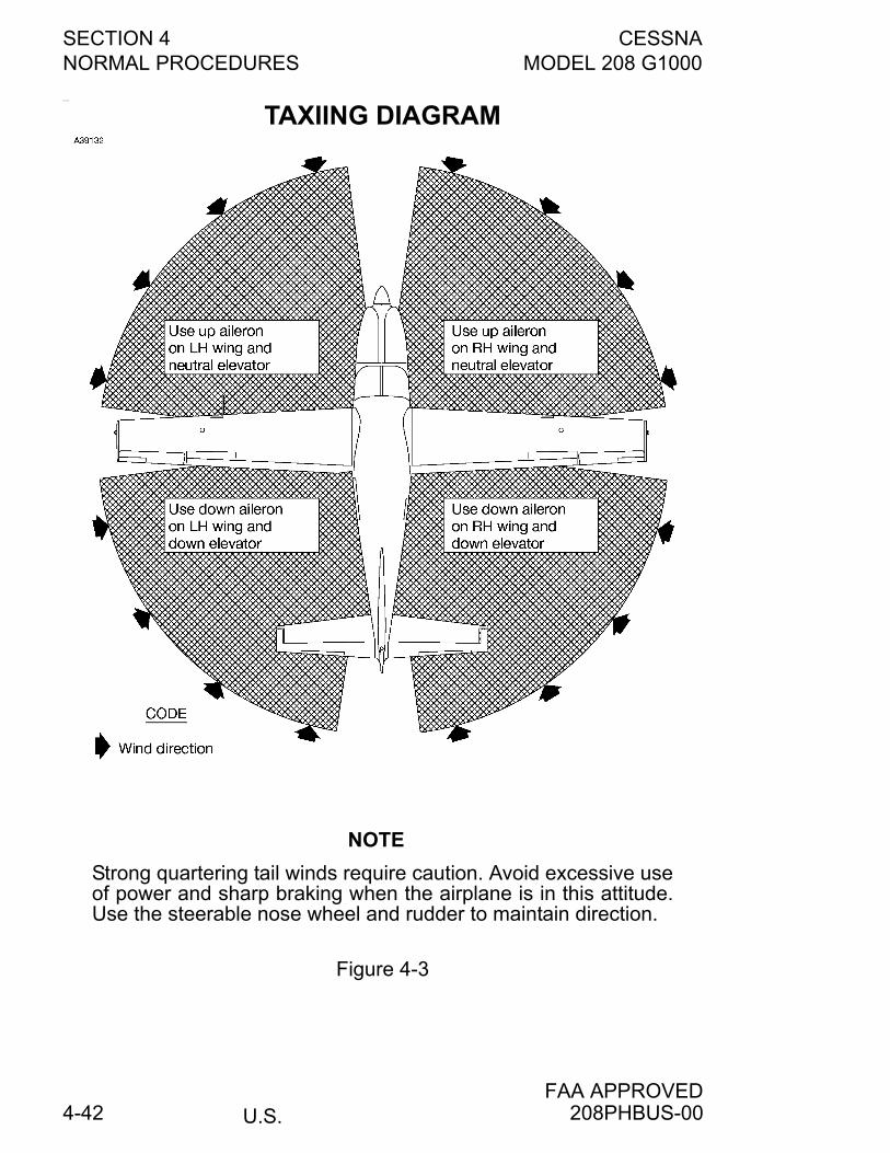
SECTION 4 CESSNANORMAL PROCEDURES MODEL 208 G1000
U.S.FAA APPROVED
4-42
__
TAXIING DIAGRAM
NOTE
Strong quartering tail winds require caution. Avoid excessive useof power and sharp braking when the airplane is in this attitude.Use the steerable nose wheel and rudder to maintain direction.
Figure 4-3
208PHBUS-00
CESSNA SECTION 4MODEL 208 G1000 NORMAL PROCEDURES
U.S.FAA APPROVED
4-43
BEFORE TAKEOFFThe FUEL TANK SELECTORS are normally both ON for takeoff and allflight operations. However, one side can be turned OFF as required tobalance the fuel load.
WARNING
• Do not exceed 200 pounds fuel imbalance inflight.
• To obtain accurate fuel quantity indicatorreadings, verify the airplane is parked in alaterally level condition; or, if in flight, make surethe airplane is in a coordinated and stabilizedcondition.
When checking the INERTIAL SEPARATOR with engine power set at400 foot-pounds, it is typical to see an approximate 25 foot-pound dropin torque when the T-handle is pulled to the BYPASS position. Thistorque drop will vary some with wind conditions during static check.A neutral index mark is added to the pedestal cover which correspondsto the zero degree trim tab position. As loadings vary towards theforward C.G. limit or aft C.G. limit, elevator trim settings towards thenose up and nose down ends of this takeoff range, respectively, willprovide comfortable control wheel forces during takeoff and initial climb.Prior to takeoff, the FUEL CONDITION Lever is moved forward to theHIGH IDLE position (approximately 65% Ng) to remain in this positionuntil after landing. The higher gas generator idle speed for flightprovides faster engine acceleration when adding power (from an idlecondition) on approach or for a balked landing go-around.
208PHBUS-00
SECTION 4 CESSNANORMAL PROCEDURES MODEL 208 G1000
U.S.FAA APPROVED
4-44
TAKEOFF
POWER SETTINGRefer to the Maximum Engine Torque for Takeoff chart in Section 5 todetermine the torque corresponding to the surface altitude and OATconditions. This torque should be obtainable without exceeding 805°CITT or 101.6% Ng.Takeoff roll is most smoothly initiated by gradually advancing thePOWER Lever until propeller RPM nears 1900. Smoothly release thebrakes and continue advancing the POWER Lever until the takeofftorque is reached.
NOTE
As airspeed increases during takeoff, an increase in torqueat a fixed POWER Lever position is normal and need not bereduced provided the torque limit (1865 foot-pounds) is notexceeded.
WING FLAP SETTINGSA flap setting of 20° is recommended for all takeoffs unless a strongcrosswind exists at which time 10° flaps may be preferred. Use of 20°flaps provides for a lower liftoff speed, as well as a reduction in groundroll and total distance over an obstacle compared to takeoff with flapsup.Flap settings greater than 20° are not approved for takeoff.
SHORT FIELD TAKEOFFIf an obstruction dictates the use of a steep climb angle after liftoff,accelerate to and climb at an obstacle clearance speed of 82 KIAS with20° flaps. Takeoff performance data is shown in Section 5 based on thisspeed and configuration.
NOTE
The 82 KIAS obstacle clearance speed is a recommendedsafe speed under all conditions, including turbulence andcomplete engine failure. The actual VX speed with flaps 20°is 77 KIAS at maximum takeoff weight as noted in the ClimbGradient - Takeoff Flap Setting - Flaps 20 chart in Section 5.
After clearing the obstacle, and reaching a safe altitude, the flaps canbe retracted slowly as the airplane accelerates to the normal climbairspeed.
(Continued Next Page)
208PHBUS-02
CESSNA SECTION 4MODEL 208 G1000 NORMAL PROCEDURES
U.S.FAA APPROVED
4-45
SHORT FIELD TAKEOFF (Continued)
Minimum ground roll takeoffs are accomplished by using 20° flaps,lifting the nose wheel off the ground as soon as practical and leavingthe ground in a slightly tail-low attitude. However, after liftoff theairplane should be leveled immediately to accelerate to a safe climbairspeed.
TYPE II, TYPE III OR TYPE IV ANTI-ICE FLUID TAKEOFFWhen Type II, Type III or Type IV anti-ice fluid is applied to the airplane,a rotation speed of 89 KIAS with flaps UP is required. Use of flaps UPallows the airplane to accelerate to a higher rotation speed without anyliftoff tendencies, which is required for the Type II, Type III or Type IVanti-ice fluid to be effective. Takeoff performance data shown in Section5 is based on this speed and configuration.
CROSSWIND TAKEOFFTakeoffs into strong crosswinds normally are performed with FLAPS10° or 20°. With the ailerons partially deflected into the wind, theairplane is accelerated to a speed higher than normal, and then rotatedto prevent settling back to the runway. When clear of the ground, makea coordinated turn into the wind to correct for drift. The use of flaps 10°will improve directional control, but will also increase the takeoffdistance. Increase the flaps 20° short field takeoff lift off and 50 feetobstacle speeds by 7 knots, if flaps 10° is used for takeoff.
ENROUTE CLIMBNormally, maximum climb power is maintained during the climb tocruise altitude. Adjust the POWER Lever as required to preventexceeding maximum climb torque, maximum climb ITT of 765°C, ormaximum climb Ng of 101.6%, whichever occurs first.At lower altitudes and cool outside air temperatures (belowapproximately 10,000 feet), the engine will reach the torque limit beforereaching the ITT or Ng limit. As the climb progresses and the torque ismaintained by POWER Lever advancement, the ITT and Ng willincrease until an altitude is reached where ITT or Ng will dictatePOWER Lever positioning. When operating near the ITT limit, advancePOWER Lever slowly to allow the current ITT to be indicated. The rateof power (and temperature) increase of the engine is greater than theresponse rate of the ITT indicating system; therefore, a rapid POWERLever advance could allow an over-temperature condition to existmomentarily in the engine before the over-temperature would beindicated.
(Continued Next Page)
208PHBUS-02
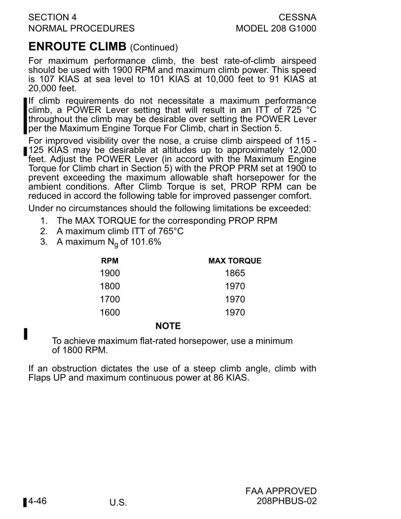
SECTION 4 CESSNANORMAL PROCEDURES MODEL 208 G1000
U.S.FAA APPROVED
4-46
ENROUTE CLIMB (Continued)
For maximum performance climb, the best rate-of-climb airspeedshould be used with 1900 RPM and maximum climb power. This speedis 107 KIAS at sea level to 101 KIAS at 10,000 feet to 91 KIAS at20,000 feet.If climb requirements do not necessitate a maximum performanceclimb, a POWER Lever setting that will result in an ITT of 725 °Cthroughout the climb may be desirable over setting the POWER Leverper the Maximum Engine Torque For Climb, chart in Section 5.For improved visibility over the nose, a cruise climb airspeed of 115 -125 KIAS may be desirable at altitudes up to approximately 12,000feet. Adjust the POWER Lever (in accord with the Maximum EngineTorque for Climb chart in Section 5) with the PROP PRM set at 1900 toprevent exceeding the maximum allowable shaft horsepower for theambient conditions. After Climb Torque is set, PROP RPM can bereduced in accord the following table for improved passenger comfort. Under no circumstances should the following limitations be exceeded:
1. The MAX TORQUE for the corresponding PROP RPM2. A maximum climb ITT of 765°C3. A maximum Ng of 101.6%
NOTE
To achieve maximum flat-rated horsepower, use a minimumof 1800 RPM.
If an obstruction dictates the use of a steep climb angle, climb withFlaps UP and maximum continuous power at 86 KIAS.
RPM MAX TORQUE
1900 1865
1800 1970
1700 1970
1600 1970
208PHBUS-02
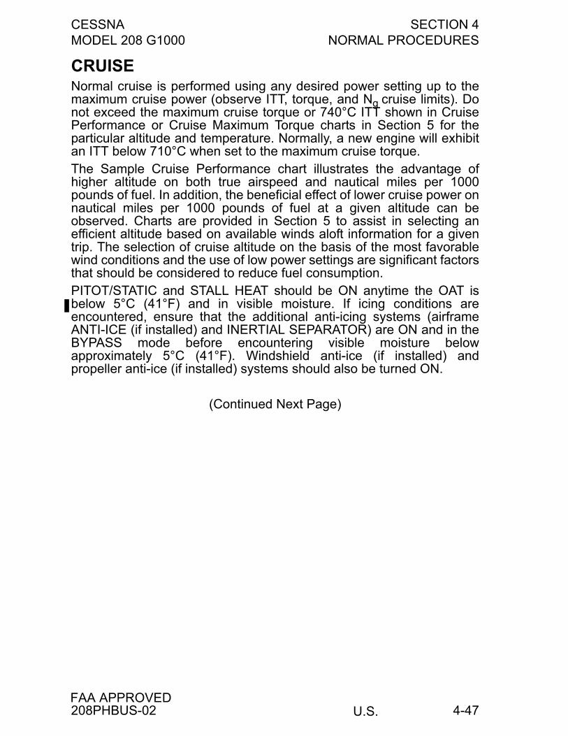
CESSNA SECTION 4MODEL 208 G1000 NORMAL PROCEDURES
U.S.FAA APPROVED
4-47
CRUISENormal cruise is performed using any desired power setting up to themaximum cruise power (observe ITT, torque, and Ng cruise limits). Donot exceed the maximum cruise torque or 740°C ITT shown in CruisePerformance or Cruise Maximum Torque charts in Section 5 for theparticular altitude and temperature. Normally, a new engine will exhibitan ITT below 710°C when set to the maximum cruise torque.The Sample Cruise Performance chart illustrates the advantage ofhigher altitude on both true airspeed and nautical miles per 1000pounds of fuel. In addition, the beneficial effect of lower cruise power onnautical miles per 1000 pounds of fuel at a given altitude can beobserved. Charts are provided in Section 5 to assist in selecting anefficient altitude based on available winds aloft information for a giventrip. The selection of cruise altitude on the basis of the most favorablewind conditions and the use of low power settings are significant factorsthat should be considered to reduce fuel consumption.PITOT/STATIC and STALL HEAT should be ON anytime the OAT isbelow 5°C (41°F) and in visible moisture. If icing conditions areencountered, ensure that the additional anti-icing systems (airframeANTI-ICE (if installed) and INERTIAL SEPARATOR) are ON and in theBYPASS mode before encountering visible moisture belowapproximately 5°C (41°F). Windshield anti-ice (if installed) andpropeller anti-ice (if installed) systems should also be turned ON.
(Continued Next Page)
208PHBUS-02
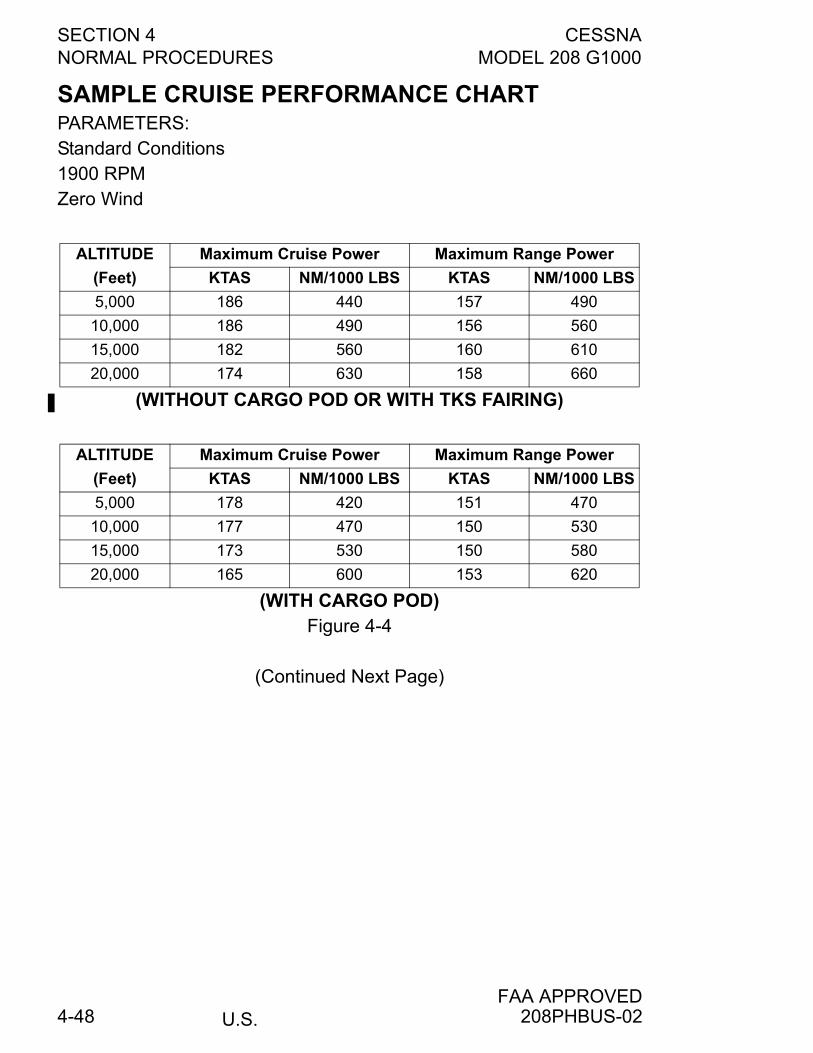
SECTION 4 CESSNANORMAL PROCEDURES MODEL 208 G1000
U.S.FAA APPROVED
4-48
SAMPLE CRUISE PERFORMANCE CHARTPARAMETERS:Standard Conditions1900 RPMZero Wind
(WITHOUT CARGO POD OR WITH TKS FAIRING)
(WITH CARGO POD)Figure 4-4
(Continued Next Page)
ALTITUDE
(Feet)
Maximum Cruise Power Maximum Range Power
KTAS NM/1000 LBS KTAS NM/1000 LBS
5,000 186 440 157 490
10,000 186 490 156 560
15,000 182 560 160 610
20,000 174 630 158 660
ALTITUDE
(Feet)
Maximum Cruise Power Maximum Range Power
KTAS NM/1000 LBS KTAS NM/1000 LBS
5,000 178 420 151 470
10,000 177 470 150 530
15,000 173 530 150 580
20,000 165 600 153 620
208PHBUS-02
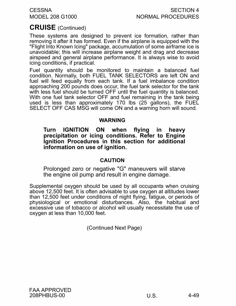
CESSNA SECTION 4MODEL 208 G1000 NORMAL PROCEDURES
U.S.FAA APPROVED
4-49
CRUISE (Continued)
These systems are designed to prevent ice formation, rather thanremoving it after it has formed. Even if the airplane is equipped with the"Flight Into Known Icing" package, accumulation of some airframe ice isunavoidable; this will increase airplane weight and drag and decreaseairspeed and general airplane performance. It is always wise to avoidicing conditions, if practical.Fuel quantity should be monitored to maintain a balanced fuelcondition. Normally, both FUEL TANK SELECTORS are left ON andfuel will feed equally from each tank. If a fuel imbalance conditionapproaching 200 pounds does occur, the fuel tank selector for the tankwith less fuel should be turned OFF until the fuel quantity is balanced.With one fuel tank selector OFF and fuel remaining in the tank beingused is less than approximately 170 lbs (25 gallons), the FUELSELECT OFF CAS MSG will come ON and a warning horn will sound.
WARNING
Turn IGNITION ON when flying in heavyprecipitation or icing conditions. Refer to EngineIgnition Procedures in this section for additionalinformation on use of ignition.
CAUTION
Prolonged zero or negative "G" maneuvers will starvethe engine oil pump and result in engine damage.
Supplemental oxygen should be used by all occupants when cruisingabove 12,500 feet. It is often advisable to use oxygen at altitudes lowerthan 12,500 feet under conditions of night flying, fatigue, or periods ofphysiological or emotional disturbances. Also, the habitual andexcessive use of tobacco or alcohol will usually necessitate the use ofoxygen at less than 10,000 feet.
(Continued Next Page)
208PHBUS-00
SECTION 4 CESSNANORMAL PROCEDURES MODEL 208 G1000
U.S.FAA APPROVED
4-50
CRUISE (Continued)
WARNING
• Operation up to the maximum allowableoperating altitude is predicated on theavailability and use of supplemental oxygenabove 12,500 feet as specified by 14 CFR 91.211.
• Smoking is prohibited when using oxygen. Oil,grease, soap, lipstick, lip balm, and other fattymaterials constitute a serious fire hazard when incontact with oxygen. Be sure hands and clothingare oil-free before handling oxygen equipment.
STALLSStall characteristics are conventional and aural warning is provided bya stall warning horn which sounds between 5 and 10 knots above thestall in all configurations.Idle-power stall speeds at maximum weight for both forward and aftC.G. are presented in Section 5.
NOTE
Practice of stalls should be done conservatively and withsufficient altitude for a safe recovery.
208PHBUS-00
CESSNA SECTION 4MODEL 208 G1000 NORMAL PROCEDURES
U.S.FAA APPROVED
4-51
LANDING
NORMAL LANDINGNormal landing approaches can be made with power-on or idle powerwith any flap setting desired and the PROP RPM Lever set at 1900.Use of FULL flaps is normally preferred to minimize touchdown speedand subsequent need for braking. For a given flap setting, surfacewinds and turbulence are usually the primary factors in determining themost comfortable approach speed.Actual touchdown should be made with idle power and on the mainwheels first, just slightly above stall speed. The nose wheel is thengently lowered to the runway, the POWER Lever repositioned to theBETA range, and brakes applied as required. When clear of therunway, reposition the FUEL CONDITION Lever from HIGH IDLE toLOW IDLE. This will reduce cabin and exterior noise levels as well asreduce braking requirements when the POWER Lever is positionedahead of the REVERSE range. Landings on rough or soft fields areaccomplished in a similar manner except that the nose wheel islowered to the runway at a lower speed to prevent excessive nose gearloads.
NOTE
The use of BETA range after touchdown is recommendedto reduce brake wear. Generally, the POWER Lever can bemoved aft of the IDLE gate until it contacts a spring in thecontrol quadrant without substantial propeller erosion fromloose debris on the runway or taxiway.
SHORT FIELD LANDINGFor short field landings, make a power approach at 78 KIAS with thePROP RPM lever at MAX (full forward) and with full flaps. After allapproach obstacles are cleared, reduce power to idle. Maintain 78KIAS approach speed by lowering the nose of the airplane. Touchdownshould be made with the POWER Lever at IDLE, and on the mainwheels first. Immediately after touchdown, lower the nose gear,reposition the POWER Lever against the spring in the BETA range, andapply heavy braking as required.For maximum brake effectiveness after all three wheels are on theground, hold full nose up elevator and apply maximum possible brakepressure without sliding the tires.
(Continued Next Page)
208PHBUS-00
SECTION 4 CESSNANORMAL PROCEDURES MODEL 208 G1000
U.S.FAA APPROVED
4-52
SHORT FIELD LANDING (Continued)
The landing performance in Section 5 is based on the aboveprocedure. A reduction in ground roll of approximately 10% will resultfrom the use of reverse thrust (POWER Lever full aft to provideincreased power from the gas generator and a reverse thrust propellerblade angle).
CAUTION
To minimize propeller blade erosion or possiblepropeller blade damage, reverse thrust should be usedonly when necessary to shorten the ground roll.Bringing the propeller out of reverse beforedecelerating through approximately 25 knots willminimize propeller erosion.
CROSSWIND LANDINGFor crosswind approaches, either the wing-low, crab or combinationmethod can be used. A flap setting between 10° and 30° isrecommended. Use a minimum flap setting for the field length. Aftertouchdown, lower the nose wheel and maintain control. Maintain astraight course using the steerable nose wheel, ailerons, andoccasional braking if necessary.
BALKED LANDINGIn a balked landing (go-around) climb, the wing flap setting should bereduced to 20° after takeoff power is applied. After all obstacles arecleared and a safe altitude and airspeed are obtained, the WINGFLAPS should be retracted.
208PHBUS-00
CESSNA SECTION 4MODEL 208 G1000 NORMAL PROCEDURES
U.S.FAA APPROVED
4-53
AFTER SHUTDOWNIf dusty conditions exist or if the last flight of the day has beencompleted, install engine inlet covers to protect the engine from debris.The covers can be installed after the engine has cooled (ITT indicatorshowing "off scale" temperature). Secure the propeller to preventwindmilling since no oil pressure is available for engine lubricationwhen the engine is not running.
COLD WEATHER OPERATIONSpecial consideration should be given to the operation of the airplanefuel system during the winter season or prior to any flight in coldtemperatures. Proper preflight draining of the fuel system is especiallyimportant and will eliminate any free water accumulation. The use of anadditive is required for anti-ice protection. Refer to Section 8 forinformation on the proper use of additives.Cold weather often causes conditions which require special care priorto flight. Operating the elevator and aileron trim tabs through their fulltravel in both directions will assure smooth operation by reducing anystiffness in these systems caused by the cold weather effects onsystem lubrication. Even small accumulations of frost, ice, snow orslush must be removed, particularly from wing, tail and all controlsurfaces to assure satisfactory flight performance and handling. Also,control surfaces must be free of any internal accumulations of ice orsnow.The use of an external pre-heater reduces wear and abuse to theengine and the electrical system. Pre-heat will lower the viscosity of theoil trapped in the oil cooler, prior to starting in extremely coldtemperatures.Use of an GPU is recommended when ambient temperatures arebelow -18°C (0°F). Assure that oil temperature is in the green band(10°C to 99°C) prior to takeoff.If snow or slush covers the takeoff surface, allowance must be made fortakeoff distances which will be increasingly extended as the snow orslush depth increases. The depth and consistency of this cover can, infact, prevent takeoff in many instances.
HIGH ALTITUDE OPERATIONAt altitudes above 20,000 feet, a compressor surge can be experiencedif engine power is rapidly re-applied immediately after a powerreduction. This characteristic is not detrimental to the engine and canbe eliminated completely by turning BLEED AIR HEAT ON andadjusting the TEMP HOT knob to at least the one-half setting.
208PHBUS-00
SECTION 4 CESSNANORMAL PROCEDURES MODEL 208 G1000
U.S.FAA APPROVED
4-54
ENGINE COMPRESSOR STALLSAn engine compressor stall can be noted by a single or multiple loudpopping noise from the engine compartment. This situation can beresolved by reducing the engine power to a point where the "popping"discontinues, and slowly advancing the throttle to the necessary settingfor continued flight. The use of BLEED AIR HEAT can also helpeliminate engine compressor stalls if this situation is encountered.
NOISE CHARACTERISTICSIncreased emphasis on improving the quality of our environmentrequires renewed effort on the part of all pilots to minimize the effect ofairplane noise on the public.We, as pilots, can demonstrate our concern for environmentalimprovement, by application of the following suggested procedures,and thereby tend to build public support for aviation:
1. Pilots operating aircraft under VFR over outdoor assemblies ofpersons, recreational and park areas, and other noise-sensitiveareas should make every effort to fly not less than 2000 feetabove the surface, weather permitting, even though flight at alower level can be consistent with the provisions of governmentregulations.
2. During departure from or approach to an airport, climb aftertakeoff and descent for landing should be made so as to avoidprolonged flight at low altitude near noise-sensitive areas.
NOTE
The above recommended procedures do not apply wherethey would conflict with Air Traffic Control clearances orinstructions, or where, in the pilot's judgment, an altitude ofless than 2000 feet is necessary for him to adequatelyexercise his duty to see and avoid other aircraft.
The certificated noise level for the Model 208 at 8000 pounds maximumweight is 79.0 dB(A). These measurements were obtained using atakeoff profile. No determination has been made by the FederalAviation Administration that the noise levels of this airplane are orshould be acceptable or unacceptable for operation at, into, or out of,any airport.
208PHBUS-00
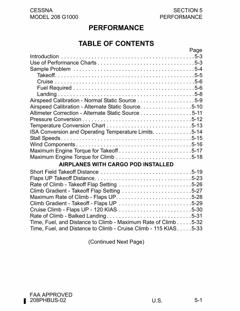
CESSNA SECTION 5MODEL 208 G1000 PERFORMANCE
U.S.FAA APPROVED
5-1
PERFORMANCE
TABLE OF CONTENTSPage
Introduction . . . . . . . . . . . . . . . . . . . . . . . . . . . . . . . . . . . . . . . . . . . .5-3Use of Performance Charts . . . . . . . . . . . . . . . . . . . . . . . . . . . . . . . .5-3Sample Problem . . . . . . . . . . . . . . . . . . . . . . . . . . . . . . . . . . . . . . . .5-4
Takeoff. . . . . . . . . . . . . . . . . . . . . . . . . . . . . . . . . . . . . . . . . . . . . .5-5Cruise . . . . . . . . . . . . . . . . . . . . . . . . . . . . . . . . . . . . . . . . . . . . . .5-6Fuel Required . . . . . . . . . . . . . . . . . . . . . . . . . . . . . . . . . . . . . . . .5-6Landing . . . . . . . . . . . . . . . . . . . . . . . . . . . . . . . . . . . . . . . . . . . . .5-8
Airspeed Calibration - Normal Static Source . . . . . . . . . . . . . . . . . . .5-9Airspeed Calibration - Alternate Static Source. . . . . . . . . . . . . . . . .5-10Altimeter Correction - Alternate Static Source . . . . . . . . . . . . . . . . . 5-11Pressure Conversion . . . . . . . . . . . . . . . . . . . . . . . . . . . . . . . . . . . .5-12Temperature Conversion Chart . . . . . . . . . . . . . . . . . . . . . . . . . . . .5-13ISA Conversion and Operating Temperature Limits. . . . . . . . . . . . .5-14Stall Speeds . . . . . . . . . . . . . . . . . . . . . . . . . . . . . . . . . . . . . . . . . . .5-15Wind Components . . . . . . . . . . . . . . . . . . . . . . . . . . . . . . . . . . . . . .5-16Maximum Engine Torque for Takeoff . . . . . . . . . . . . . . . . . . . . . . . .5-17Maximum Engine Torque for Climb . . . . . . . . . . . . . . . . . . . . . . . . .5-18
AIRPLANES WITH CARGO POD INSTALLEDShort Field Takeoff Distance . . . . . . . . . . . . . . . . . . . . . . . . . . . . . .5-19Flaps UP Takeoff Distance. . . . . . . . . . . . . . . . . . . . . . . . . . . . . . . .5-23Rate of Climb - Takeoff Flap Setting . . . . . . . . . . . . . . . . . . . . . . . .5-26Climb Gradient - Takeoff Flap Setting . . . . . . . . . . . . . . . . . . . . . . .5-27Maximum Rate of Climb - Flaps UP. . . . . . . . . . . . . . . . . . . . . . . . .5-28Climb Gradient - Takeoff - Flaps UP . . . . . . . . . . . . . . . . . . . . . . . .5-29Cruise Climb - Flaps UP - 120 KIAS . . . . . . . . . . . . . . . . . . . . . . . .5-30Rate of Climb - Balked Landing . . . . . . . . . . . . . . . . . . . . . . . . . . . .5-31Time, Fuel, and Distance to Climb - Maximum Rate of Climb . . . . .5-32Time, Fuel, and Distance to Climb - Cruise Climb - 115 KIAS. . . . .5-33
(Continued Next Page)
208PHBUS-02
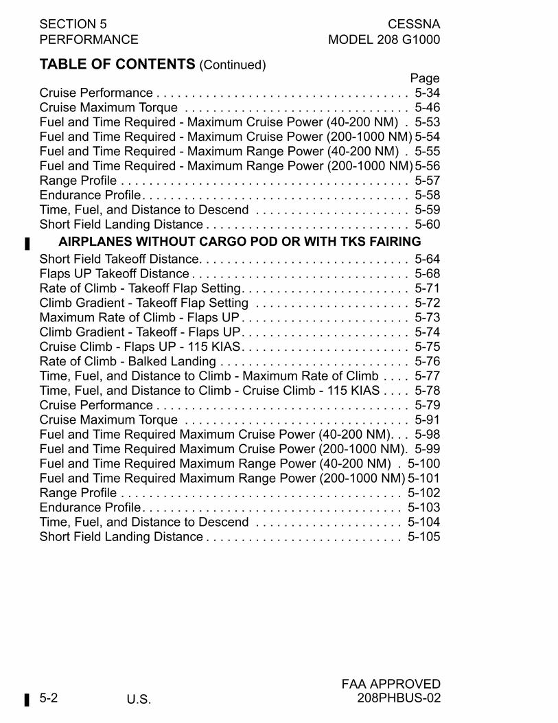
SECTION 5 CESSNAPERFORMANCE MODEL 208 G1000
U.S.FAA APPROVED
5-2
TABLE OF CONTENTS (Continued)Page
Cruise Performance . . . . . . . . . . . . . . . . . . . . . . . . . . . . . . . . . . . . 5-34Cruise Maximum Torque . . . . . . . . . . . . . . . . . . . . . . . . . . . . . . . . 5-46Fuel and Time Required - Maximum Cruise Power (40-200 NM) . 5-53Fuel and Time Required - Maximum Cruise Power (200-1000 NM) 5-54Fuel and Time Required - Maximum Range Power (40-200 NM) . 5-55Fuel and Time Required - Maximum Range Power (200-1000 NM) 5-56Range Profile . . . . . . . . . . . . . . . . . . . . . . . . . . . . . . . . . . . . . . . . . 5-57Endurance Profile. . . . . . . . . . . . . . . . . . . . . . . . . . . . . . . . . . . . . . 5-58Time, Fuel, and Distance to Descend . . . . . . . . . . . . . . . . . . . . . . 5-59Short Field Landing Distance . . . . . . . . . . . . . . . . . . . . . . . . . . . . . 5-60
AIRPLANES WITHOUT CARGO POD OR WITH TKS FAIRINGShort Field Takeoff Distance. . . . . . . . . . . . . . . . . . . . . . . . . . . . . . 5-64Flaps UP Takeoff Distance . . . . . . . . . . . . . . . . . . . . . . . . . . . . . . . 5-68Rate of Climb - Takeoff Flap Setting. . . . . . . . . . . . . . . . . . . . . . . . 5-71Climb Gradient - Takeoff Flap Setting . . . . . . . . . . . . . . . . . . . . . . 5-72Maximum Rate of Climb - Flaps UP . . . . . . . . . . . . . . . . . . . . . . . . 5-73Climb Gradient - Takeoff - Flaps UP. . . . . . . . . . . . . . . . . . . . . . . . 5-74Cruise Climb - Flaps UP - 115 KIAS. . . . . . . . . . . . . . . . . . . . . . . . 5-75Rate of Climb - Balked Landing . . . . . . . . . . . . . . . . . . . . . . . . . . . 5-76Time, Fuel, and Distance to Climb - Maximum Rate of Climb . . . . 5-77Time, Fuel, and Distance to Climb - Cruise Climb - 115 KIAS . . . . 5-78Cruise Performance . . . . . . . . . . . . . . . . . . . . . . . . . . . . . . . . . . . . 5-79Cruise Maximum Torque . . . . . . . . . . . . . . . . . . . . . . . . . . . . . . . . 5-91Fuel and Time Required Maximum Cruise Power (40-200 NM). . . 5-98Fuel and Time Required Maximum Cruise Power (200-1000 NM). 5-99Fuel and Time Required Maximum Range Power (40-200 NM) . 5-100Fuel and Time Required Maximum Range Power (200-1000 NM) 5-101Range Profile . . . . . . . . . . . . . . . . . . . . . . . . . . . . . . . . . . . . . . . . 5-102Endurance Profile. . . . . . . . . . . . . . . . . . . . . . . . . . . . . . . . . . . . . 5-103Time, Fuel, and Distance to Descend . . . . . . . . . . . . . . . . . . . . . 5-104Short Field Landing Distance . . . . . . . . . . . . . . . . . . . . . . . . . . . . 5-105
208PHBUS-02
CESSNA SECTION 5MODEL 208 G1000 PERFORMANCE
U.S.FAA APPROVED
5-3
INTRODUCTIONPerformance data charts on the following pages are presented so thatyou may know what to expect from the airplane under variousconditions, and also, to facilitate the planning of flights in detail and withreasonable accuracy. The data in the charts has been computed fromactual flight tests using average piloting techniques and an airplaneand engine in good condition and equipped with a Hartzell propeller.Airplanes equipped with a McCauley propeller will have comparableperformance and should also use the data shown.
WARNING
To make sure that performance in this section canbe duplicated, the airplane and engine must bemaintained in good condition. Pilot proficiency andproper preflight planning using data necessary forall flight phases is also required to assure expectedperformance with ample margins of safety.
It should be noted that the performance information presented in therange and endurance profile charts allows for 45 minutes reserve fuelat the specified cruise power and altitude. Some indeterminatevariables such as engine and propeller condition, and air turbulencemay account for variations of 10% or more in range and endurance.Therefore, it is important to utilize all available information to estimatethe fuel required for the particular flight.Notes have been provided on various graphs and tables toapproximate performance with the inertial separator in BYPASS and/orcabin heat on. The effect will vary, depending upon airspeed,temperature, and altitude. At lower altitudes, where operation on thetorque limit is possible, the effect of the inertial separator will be less,depending upon how much power can be recovered after the separatorvanes have been extended.In some cases, performance charts in this section include data fortemperatures which are outside of the ISA Conversion and OperatingTemperature Limits chart. This data has been included to aid ininterpolation.
USE OF PERFORMANCE CHARTS
Performance data is presented in tabular or graphical form to illustratethe effect of different variables. Sufficiently detailed information isprovided in the tables so that conservative values can be selected andused to determine the particular performance figure with reasonableaccuracy.
208PHBUS-00
SECTION 5 CESSNAPERFORMANCE MODEL 208 G1000
U.S.FAA APPROVED
5-4
SAMPLE PROBLEMThe following sample flight problem utilizes information from thevarious charts to determine the predicted performance data for a typicalflight of an airplane equipped with a cargo pod. A similar calculationcan be made for an airplane without a cargo pod using charts identifiedas appropriate for this configuration. The following information isknown:
AIRPLANE CONFIGURATION (CARGO POD INSTALLED)Takeoff weight 7850 PoundsUsable fuel 2224 Pounds
TAKEOFF CONDITIONSField pressure altitude 3500 FeetTemperature 16°C (standard + 8°C)Wind component along runway 12 Knot HeadwindField length 4000 Feet
CRUISE CONDITIONSTotal distance 650 Nautical MilesPressure altitude 11,500 FeetTemperature 8°CExpected wind enroute 10 Knot Headwind
LANDING CONDITIONSField pressure altitude 1500 FeetTemperature 25°CField length 3000 Feet
208PHBUS-00
CESSNA SECTION 5MODEL 208 G1000 PERFORMANCE
U.S.FAA APPROVED
5-5
TAKEOFFThe Short Field Takeoff Distance chart shows distances that are basedon the short field technique. Conservative distances can be establishedby reading the chart at the next higher value of weight, altitude andtemperature. For example, in this particular sample problem, the takeoffdistance information presented for a weight of 8000 pounds, pressurealtitude of 4000 feet and a temperature of 20°C should be used andresults in the following:Ground roll 1540 FeetTotal distance to clear a 50-foot obstacle 2705 FeetThese distances are well within the available takeoff field length.However, a correction for the effect of wind may be made based onNote 2 of the takeoff chart. The correction for a 12 knot headwind is:
12 Knots11 Knots X 10% = 11% Decrease
This results in the following distances, corrected for wind:
Ground roll, zero wind 1540 FeetDecrease in ground roll
(1540 feet X 11%) -169 Feet
Corrected ground roll 1371 Feet
Total distance to clear a50-foot obstacle, zero wind 2705 Feet
Decrease in total distance(2705 feet X 11%) -298 Feet
Corrected total distanceto clear a 50-foot obstacle 2407 Feet
The Maximum Engine Torque For Takeoff chart should be consulted fortakeoff power setting. For the above ambient conditions, the powersetting is:
Takeoff torque 1865 Ft-Lbs
The Maximum Engine Torque For Climb chart should be consulted forclimb power setting from field elevation to cruise altitude. For the aboveambient conditions, the power setting is:
Field Elevation Maximum Climb Torque 1740 Ft-lbsCruise Altitude Maximum Climb Torque 1360 Ft-lbs
208PHBUS-00
SECTION 5 CESSNAPERFORMANCE MODEL 208 G1000
U.S.FAA APPROVED
5-6
CRUISEThe cruising altitude should be selected based on a consideration oftrip length, winds aloft, and the airplane’s performance. A cruisingaltitude and the expected wind enroute have been given for this sampleproblem. However, the power setting selection for cruise must bedetermined based on several considerations. These include the cruiseperformance characteristics presented in the Cruise Performance,Cruise Maximum Torque charts, Fuel and Time Required, and theRange and Endurance Profile charts.The Range Profile chart shows range at maximum cruise power andalso at maximum range power. For this sample problem, maximumcruise power and 1900 RPM will be used.The Cruise Performance chart for 12,000 feet pressure altitude isentered using 10°C temperature. These values most nearly correspondto the planned altitude and expected temperature conditions. Thetorque setting for maximum cruise power is 1285 Ft-Lbs torque at 1900RPM which results in the following:
True Airspeed 165 KnotsCruise Fuel Flow 306 PPH
FUEL REQUIREDThe total fuel requirement for the flight may be estimated using theperformance information in the Time, Fuel, and Distance to Climb chart,Cruise Performance chart, and Time, Fuel, and Distance to Descendchart or in the Fuel and Time Required (Maximum Cruise Power) chartand Fuel and Time Required (Maximum Range Power) chart. Thelonger detailed method will be used for this sample problem, but theuse of Fuel and Time Required (Maximum Cruise Power) or Fuel andTime Required (Maximum Range Power) charts will provide the desiredinformation for most flight planning purposes.Assuming a maximum climb, Time, Fuel, and Distance to Climb(Maximum Rate Climb) chart may be used to determine the time, fueland distance to climb by reading values for a weight of 8000 poundsand a temperature 20°C above standard. The difference between thevalues shown in the table for 4000 feet and 12,000 feet results in thefollowing:
Time 11 MinutesFuel 65 PoundsDistance 21 Nautical Miles
(Continued Next Page)
208PHBUS-00
CESSNA SECTION 5MODEL 208 G1000 PERFORMANCE
U.S.FAA APPROVED
5-7
FUEL REQUIRED (Continued)
Similarly, Time, Fuel, and Distance to Descend chart shows that adescent from 12,000 feet to sea level results in the following:
Time 15 MinutesFuel 74 PoundsDistance 43 Nautical Miles
The distances shown on the climb and descent charts are for zerowind. A correction for the effect of wind may be made as follows:
Distance during climb with no wind 21 Nautical Miles
Decrease in distance due to wind(16/60 X 10 knot headwind) -2 Nautical Miles
Corrected distance to climb 19 Nautical Miles
Similarly, the distance for descent may be corrected for the effect ofwind and results in 40 nautical miles.The cruise distance is then determined by subtracting the distanceduring climb and distance during descent.
Total distance 650 Nautical Miles
Distance during climb and descent -59 Nautical Miles
Cruise distance 591 Nautical Miles
With an expected 10 knot headwind, the ground speed for cruise ispredicted to be:
165 Knots-10 Knots155 Knots
Therefore, the time required for the cruise portion of the trip is:591 Nautical Miles = 3.8 Hours
155 KnotsThe fuel required for cruise is:
3.8 hours X 306 pounds/hour = 1163 PoundsA 45-minute reserve requires:
45 X 306 pounds/hour = 230 Pounds60
(Continued Next Page)
208PHBUS-00
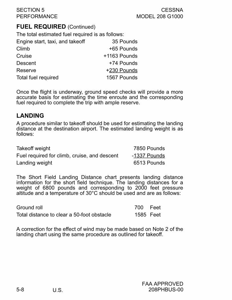
SECTION 5 CESSNAPERFORMANCE MODEL 208 G1000
U.S.FAA APPROVED
5-8
FUEL REQUIRED (Continued)
The total estimated fuel required is as follows:Engine start, taxi, and takeoff 35 PoundsClimb +65 PoundsCruise +1163 PoundsDescent +74 PoundsReserve +230 PoundsTotal fuel required 1567 Pounds
Once the flight is underway, ground speed checks will provide a moreaccurate basis for estimating the time enroute and the correspondingfuel required to complete the trip with ample reserve.
LANDINGA procedure similar to takeoff should be used for estimating the landingdistance at the destination airport. The estimated landing weight is asfollows:
Takeoff weight 7850 PoundsFuel required for climb, cruise, and descent -1337 PoundsLanding weight 6513 Pounds
The Short Field Landing Distance chart presents landing distanceinformation for the short field technique. The landing distances for aweight of 6800 pounds and corresponding to 2000 feet pressurealtitude and a temperature of 30°C should be used and are as follows:
Ground roll 700 FeetTotal distance to clear a 50-foot obstacle 1585 Feet
A correction for the effect of wind may be made based on Note 2 of thelanding chart using the same procedure as outlined for takeoff.
208PHBUS-00
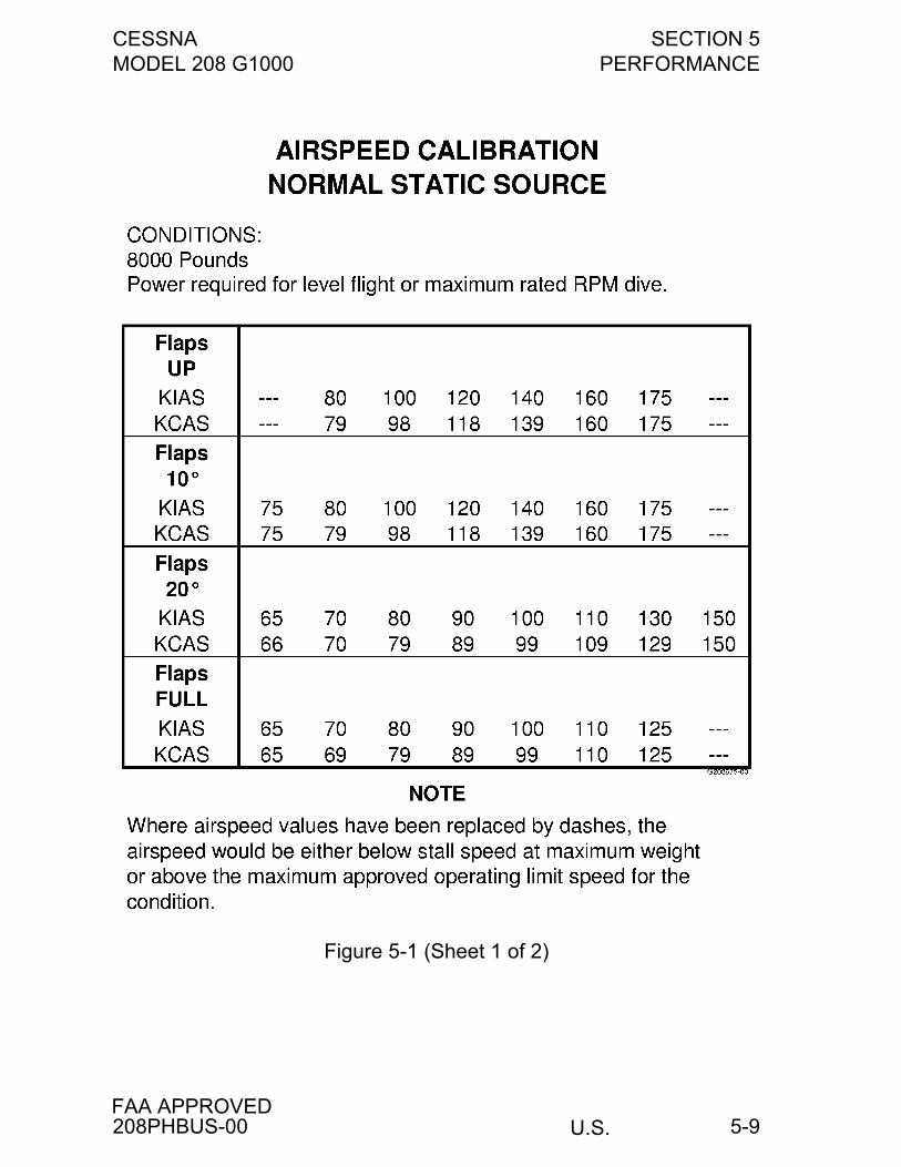
CESSNA SECTION 5MODEL 208 G1000 PERFORMANCE
U.S.FAA APPROVED
5-9
Figure 5-1 (Sheet 1 of 2)
208PHBUS-00
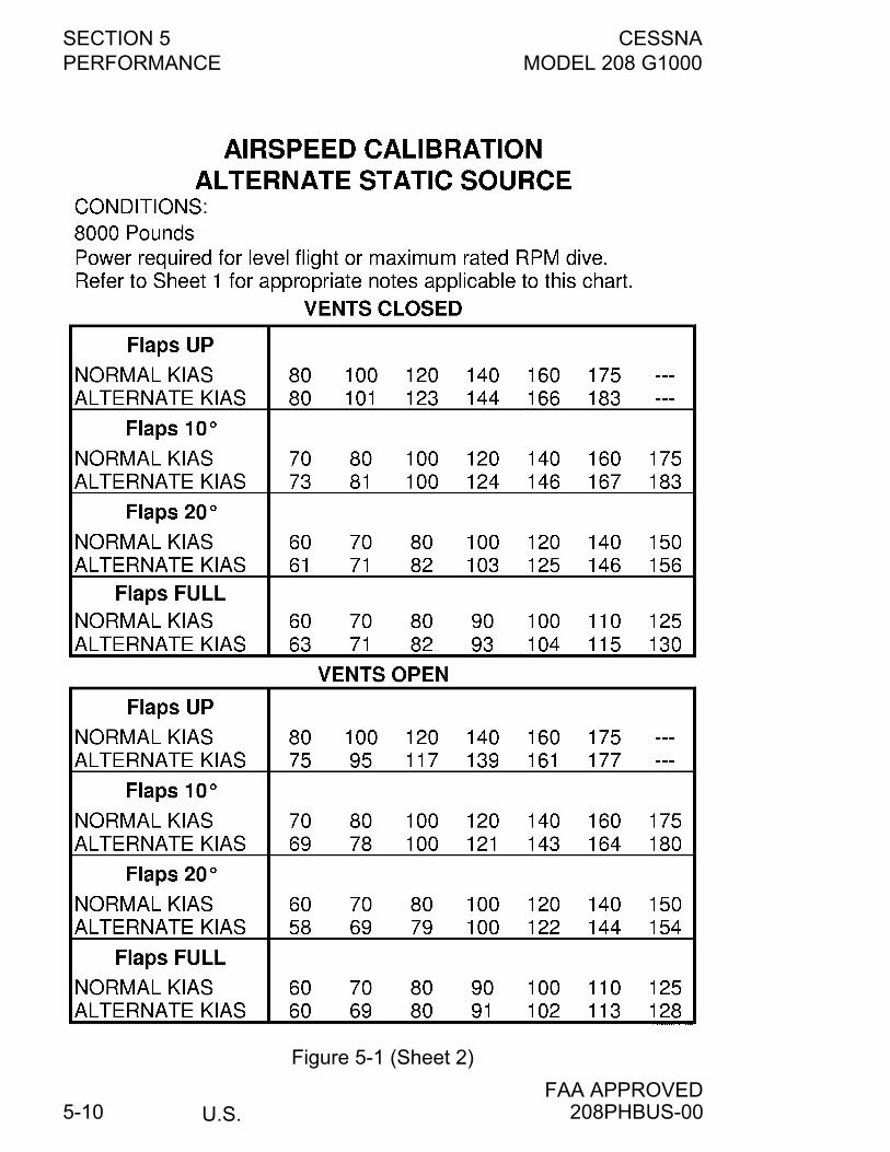
SECTION 5 CESSNAPERFORMANCE MODEL 208 G1000
U.S.FAA APPROVED
5-10
Figure 5-1 (Sheet 2)
208PHBUS-00
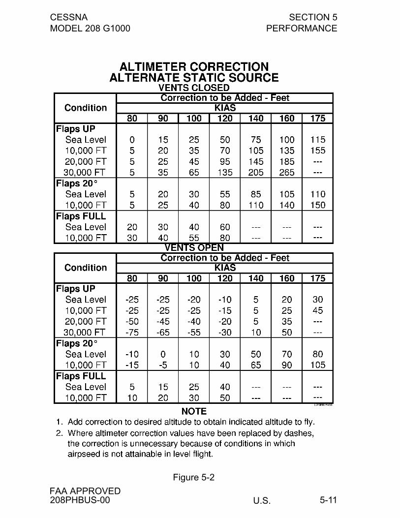
CESSNA SECTION 5MODEL 208 G1000 PERFORMANCE
U.S.FAA APPROVED
5-11
Figure 5-2
208PHBUS-00
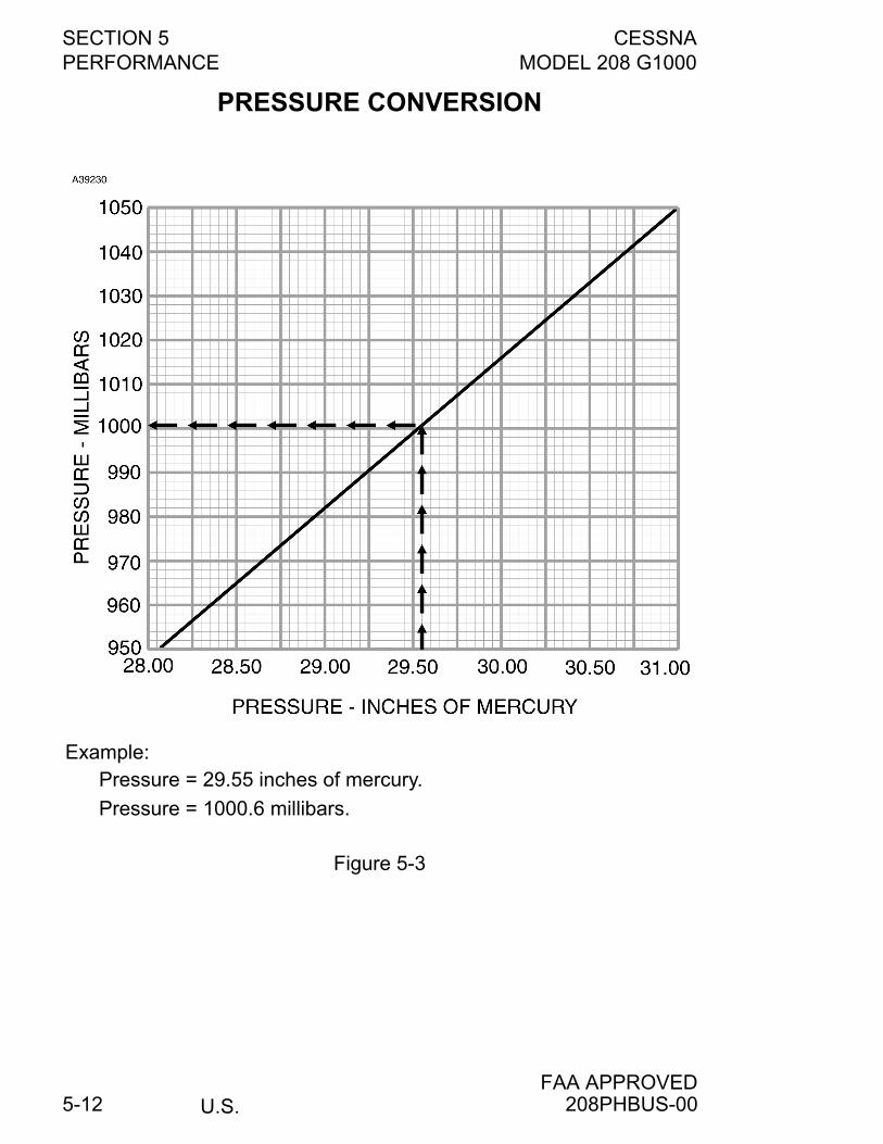
SECTION 5 CESSNAPERFORMANCE MODEL 208 G1000
U.S.FAA APPROVED
5-12
PRESSURE CONVERSION
Example: Pressure = 29.55 inches of mercury.
Pressure = 1000.6 millibars.
Figure 5-3
208PHBUS-00
CESSNA SECTION 5MODEL 208 G1000 PERFORMANCE
U.S.FAA APPROVED
5-13
TEMPERATURE CONVERSION CHART
Figure 5-4
208PHBUS-00
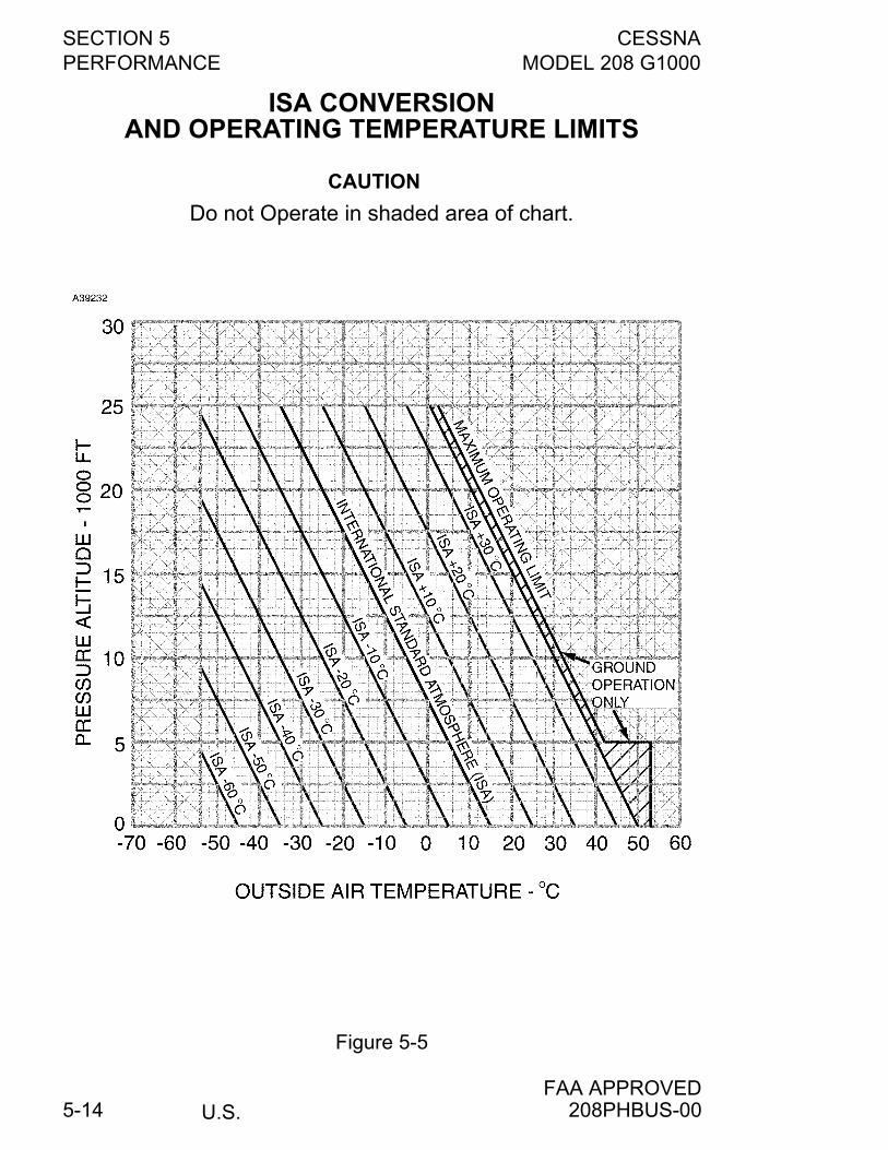
SECTION 5 CESSNAPERFORMANCE MODEL 208 G1000
U.S.FAA APPROVED
5-14
ISA CONVERSIONAND OPERATING TEMPERATURE LIMITS
CAUTION
Do not Operate in shaded area of chart.
Figure 5-5
208PHBUS-00
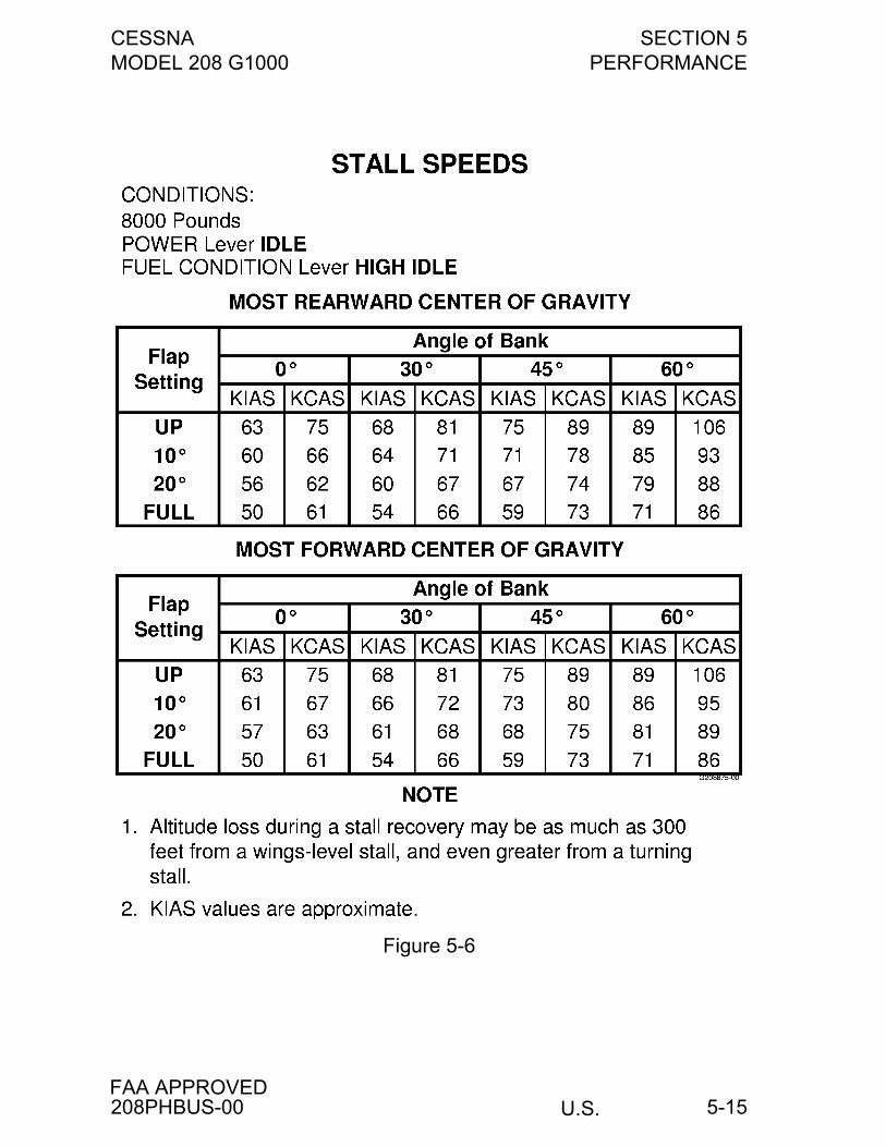
CESSNA SECTION 5MODEL 208 G1000 PERFORMANCE
U.S.FAA APPROVED
5-15
Figure 5-6
208PHBUS-00
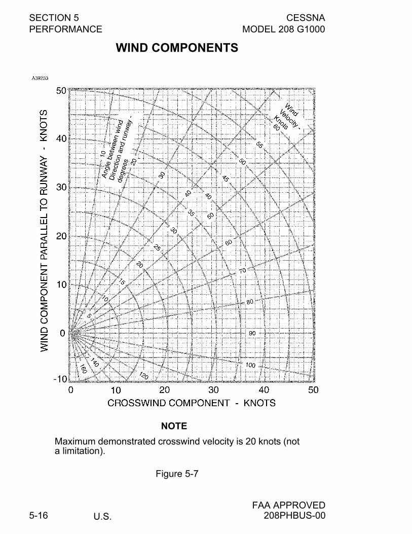
SECTION 5 CESSNAPERFORMANCE MODEL 208 G1000
U.S.FAA APPROVED
5-16
WIND COMPONENTS
NOTE
Maximum demonstrated crosswind velocity is 20 knots (nota limitation).
Figure 5-7
208PHBUS-00
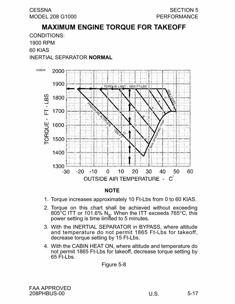
CESSNA SECTION 5MODEL 208 G1000 PERFORMANCE
U.S.FAA APPROVED
5-17
MAXIMUM ENGINE TORQUE FOR TAKEOFFCONDITIONS:1900 RPM60 KIASINERTIAL SEPARATOR NORMAL
NOTE
1. Torque increases approximately 10 Ft-Lbs from 0 to 60 KIAS.
2. Torque on this chart shall be achieved without exceeding805°C ITT or 101.6% Ng. When the ITT exceeds 765°C, thispower setting is time limited to 5 minutes.
3. With the INERTIAL SEPARATOR in BYPASS, where altitudeand temperature do not permit 1865 Ft-Lbs for takeoff,decrease torque setting by 15 Ft-Lbs.
4. With the CABIN HEAT ON, where altitude and temperature donot permit 1865 Ft-Lbs for takeoff, decrease torque setting by65 Ft-Lbs.
Figure 5-8
208PHBUS-00
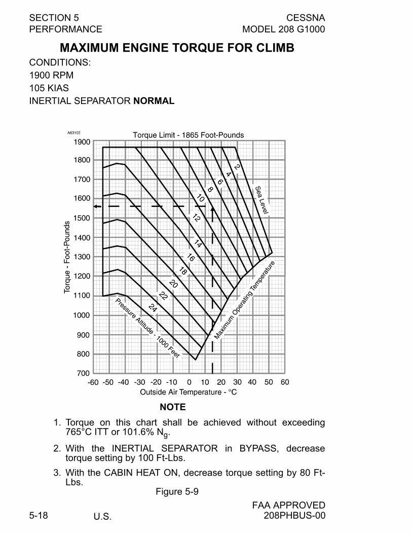
SECTION 5 CESSNAPERFORMANCE MODEL 208 G1000
U.S.FAA APPROVED
5-18
MAXIMUM ENGINE TORQUE FOR CLIMBCONDITIONS:1900 RPM105 KIASINERTIAL SEPARATOR NORMAL
NOTE
1. Torque on this chart shall be achieved without exceeding765°C ITT or 101.6% Ng.
2. With the INERTIAL SEPARATOR in BYPASS, decreasetorque setting by 100 Ft-Lbs.
3. With the CABIN HEAT ON, decrease torque setting by 80 Ft-Lbs.
Figure 5-9
208PHBUS-00
CESSNA SECTION 5MODEL 208 G1000 PERFORMANCE
U.S.FAA APPROVED
5-19
Figure 5-10 (Sheet 1 of 4)
208PHBUS-00
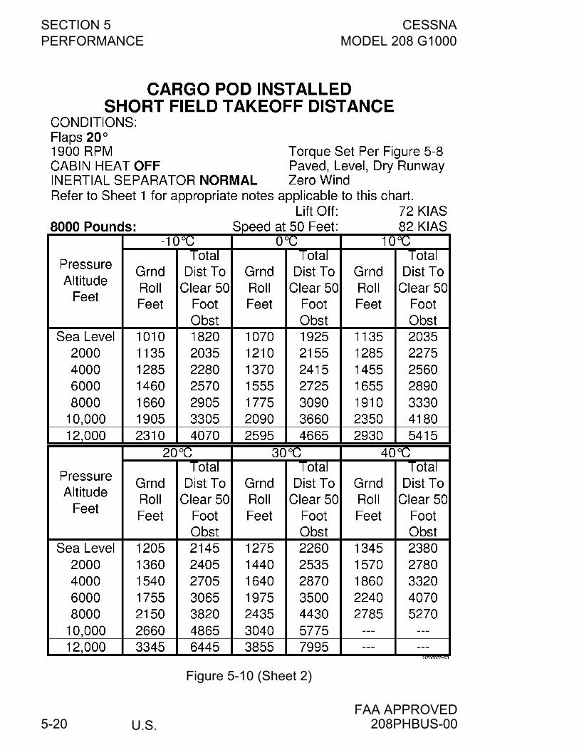
SECTION 5 CESSNAPERFORMANCE MODEL 208 G1000
U.S.FAA APPROVED
5-20
Figure 5-10 (Sheet 2)
208PHBUS-00
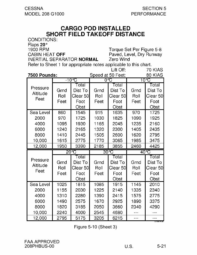
CESSNA SECTION 5MODEL 208 G1000 PERFORMANCE
U.S.FAA APPROVED
5-21
Figure 5-10 (Sheet 3)
208PHBUS-00
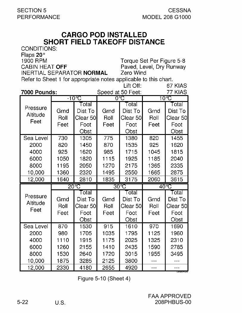
SECTION 5 CESSNAPERFORMANCE MODEL 208 G1000
U.S.FAA APPROVED
5-22
Figure 5-10 (Sheet 4)
208PHBUS-00
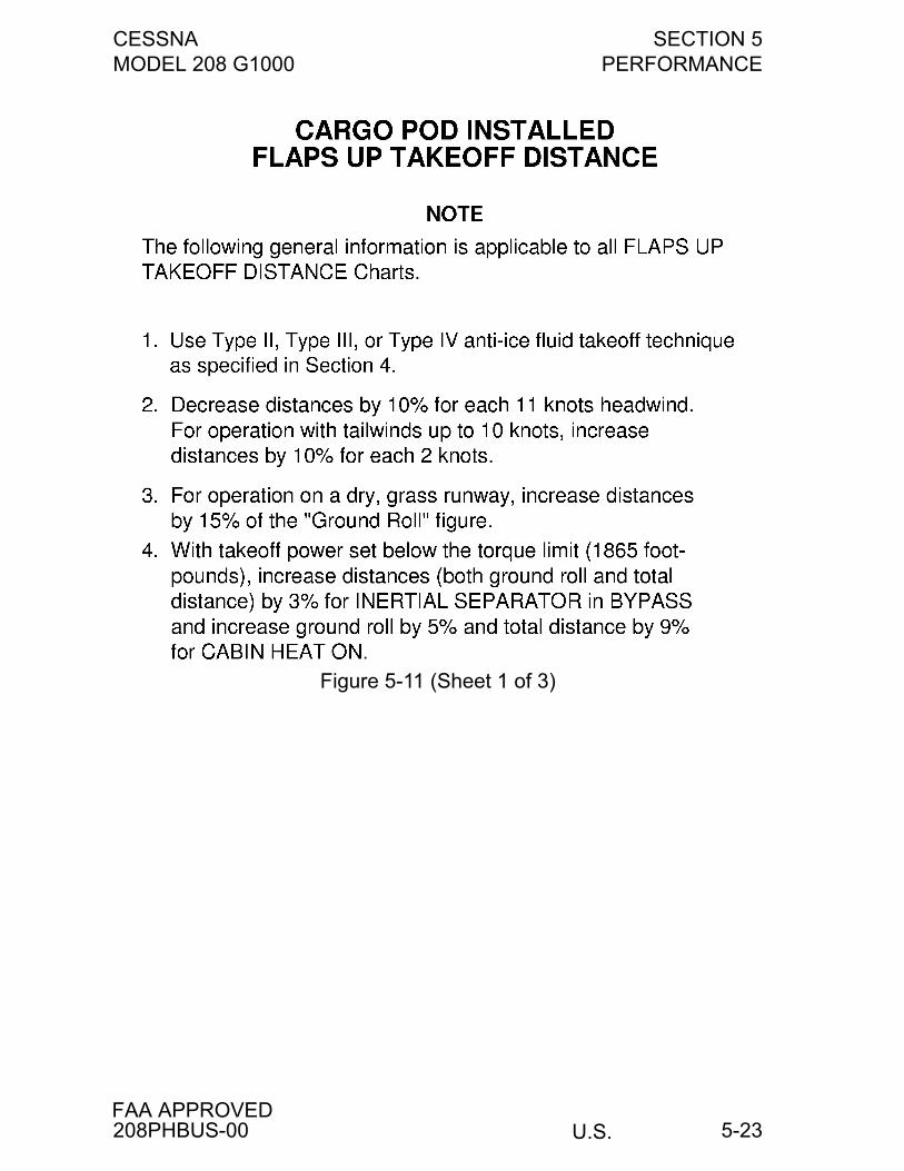
CESSNA SECTION 5MODEL 208 G1000 PERFORMANCE
U.S.FAA APPROVED
5-23
Figure 5-11 (Sheet 1 of 3)
208PHBUS-00
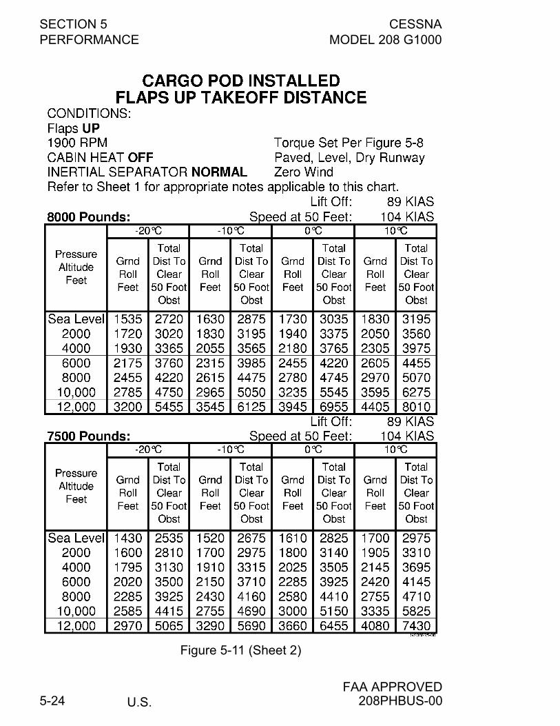
SECTION 5 CESSNAPERFORMANCE MODEL 208 G1000
U.S.FAA APPROVED
5-24
Figure 5-11 (Sheet 2)
208PHBUS-00
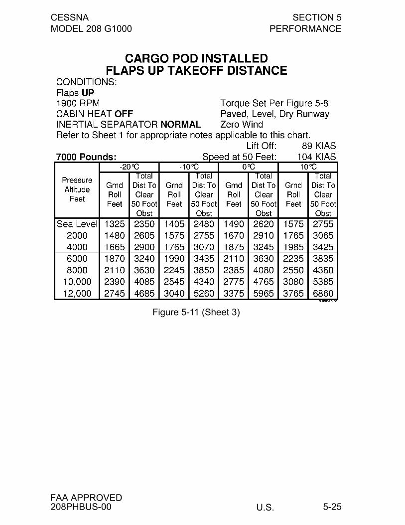
CESSNA SECTION 5MODEL 208 G1000 PERFORMANCE
U.S.FAA APPROVED
5-25
Figure 5-11 (Sheet 3)
208PHBUS-00
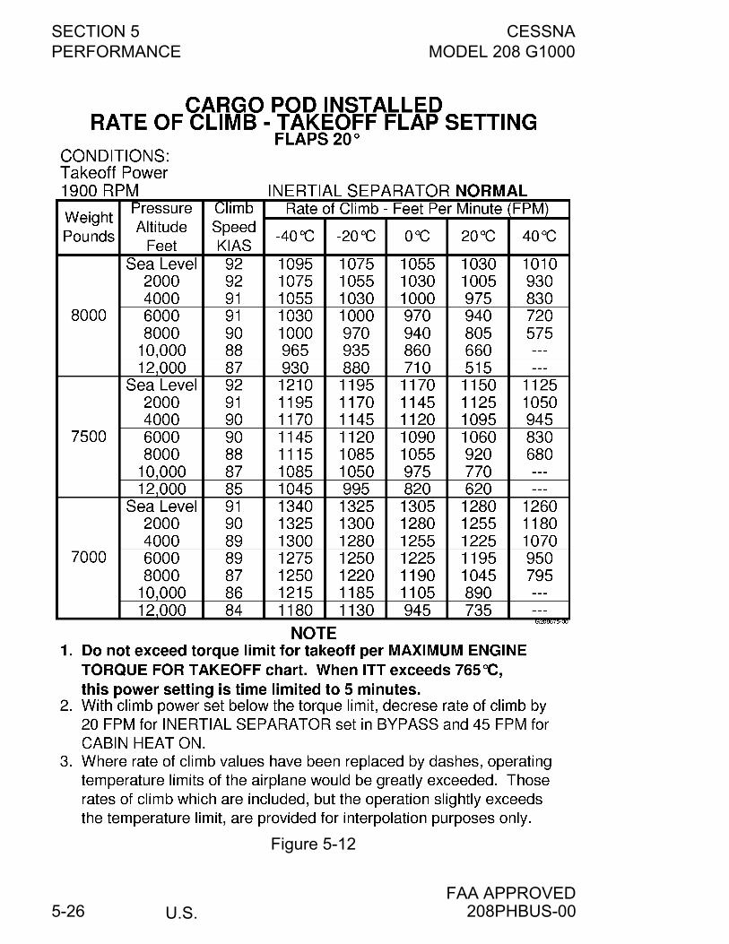
SECTION 5 CESSNAPERFORMANCE MODEL 208 G1000
U.S.FAA APPROVED
5-26
Figure 5-12
208PHBUS-00
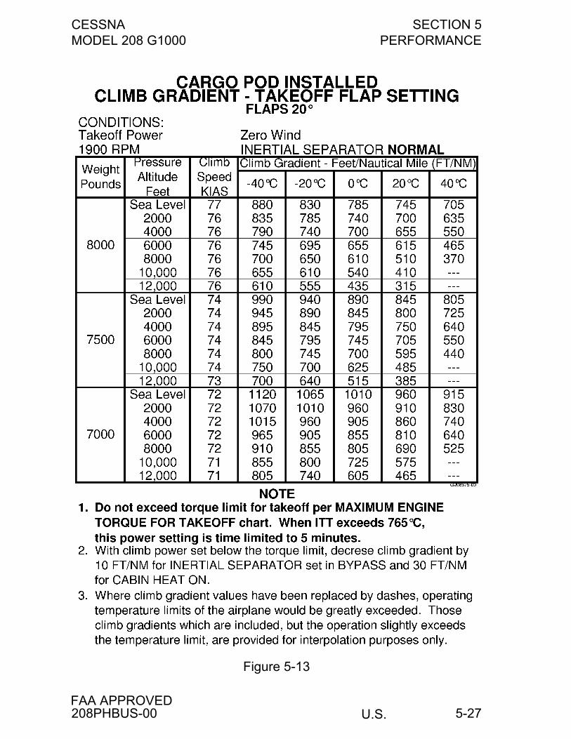
CESSNA SECTION 5MODEL 208 G1000 PERFORMANCE
U.S.FAA APPROVED
5-27
Figure 5-13
208PHBUS-00
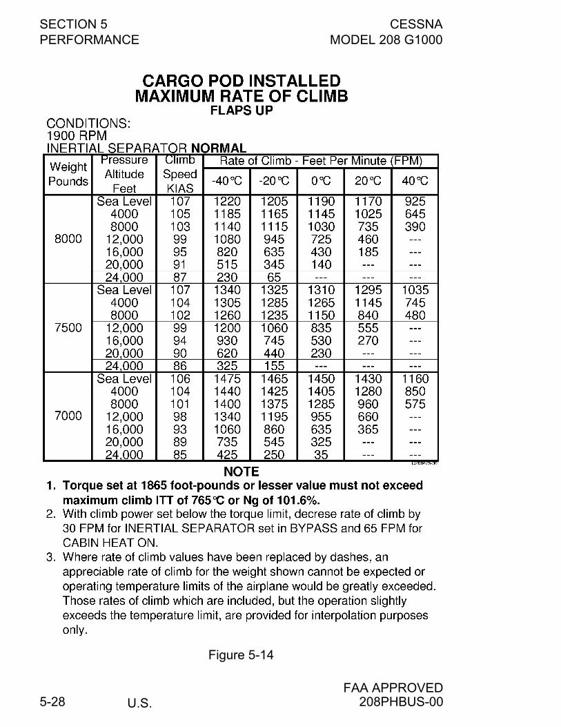
SECTION 5 CESSNAPERFORMANCE MODEL 208 G1000
U.S.FAA APPROVED
5-28
Figure 5-14
208PHBUS-00
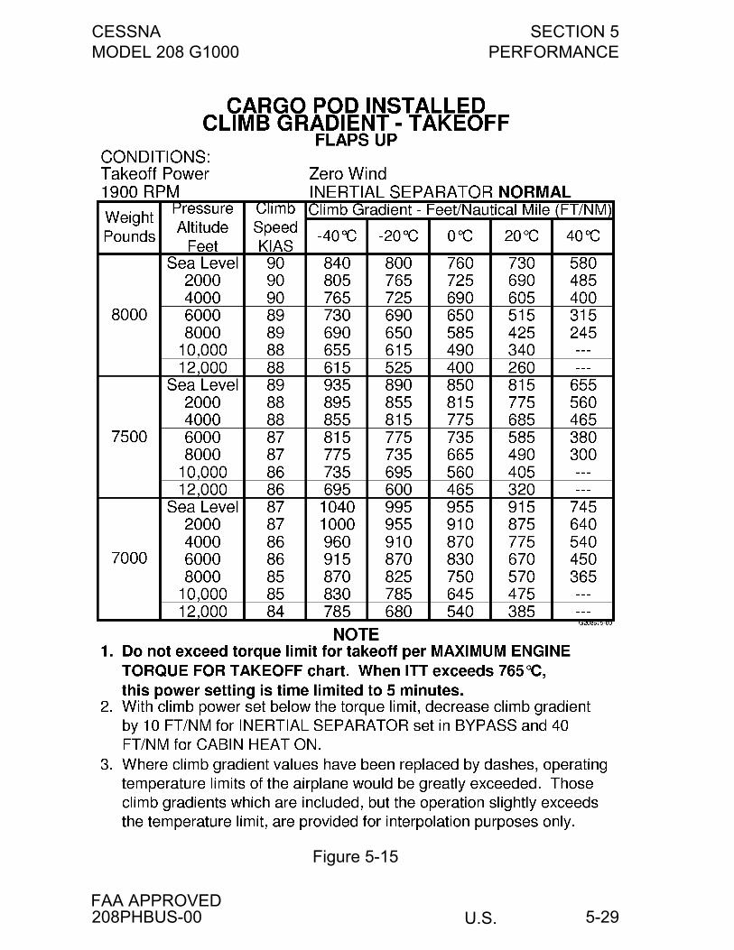
CESSNA SECTION 5MODEL 208 G1000 PERFORMANCE
U.S.FAA APPROVED
5-29
Figure 5-15
208PHBUS-00
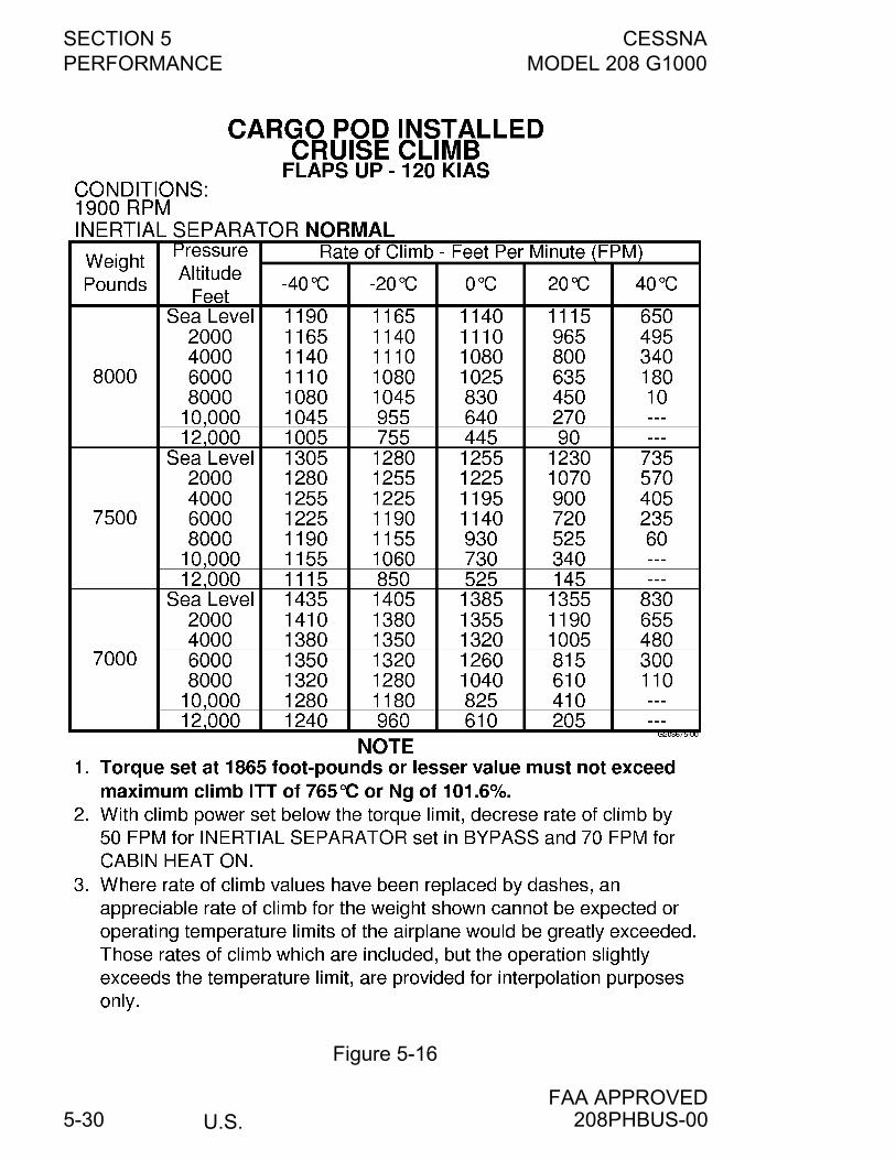
SECTION 5 CESSNAPERFORMANCE MODEL 208 G1000
U.S.FAA APPROVED
5-30
Figure 5-16
208PHBUS-00
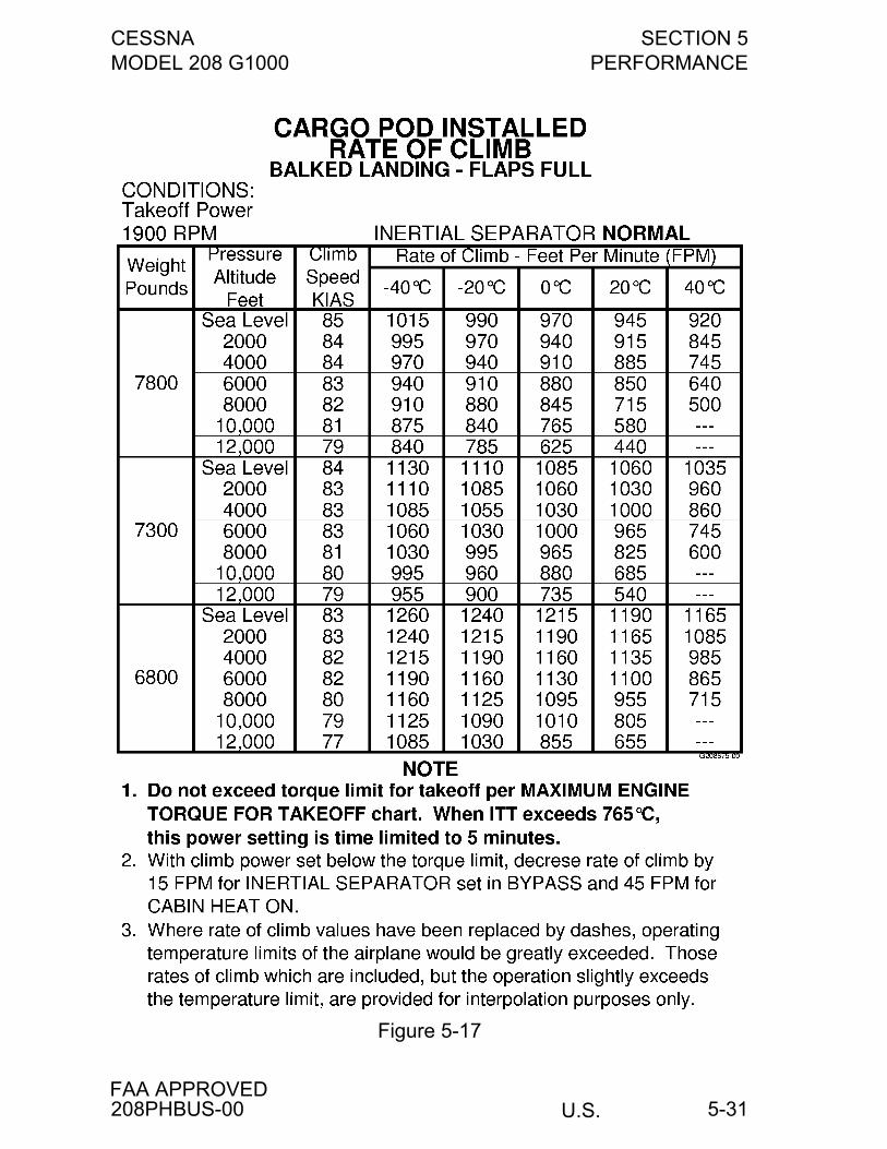
CESSNA SECTION 5MODEL 208 G1000 PERFORMANCE
U.S.FAA APPROVED
5-31
Figure 5-17
208PHBUS-00
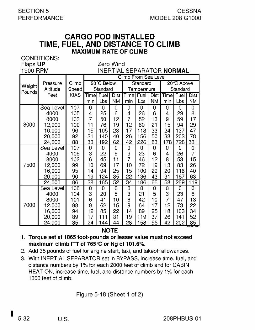
SECTION 5 CESSNAPERFORMANCE MODEL 208 G1000
U.S.5-32
Figure 5-18 (Sheet 1 of 2)
208PHBUS-01
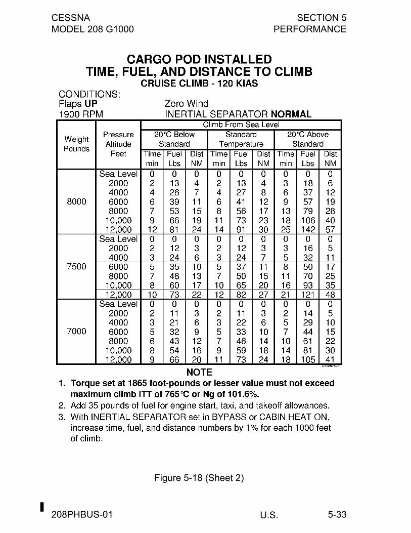
CESSNA SECTION 5MODEL 208 G1000 PERFORMANCE
U.S.
5-33
Figure 5-18 (Sheet 2)
208PHBUS-01
SECTION 5 CESSNAPERFORMANCE MODEL 208 G1000
U.S.5-34
Figure 5-19 (Sheet 1 of 12)
208PHBUS-01
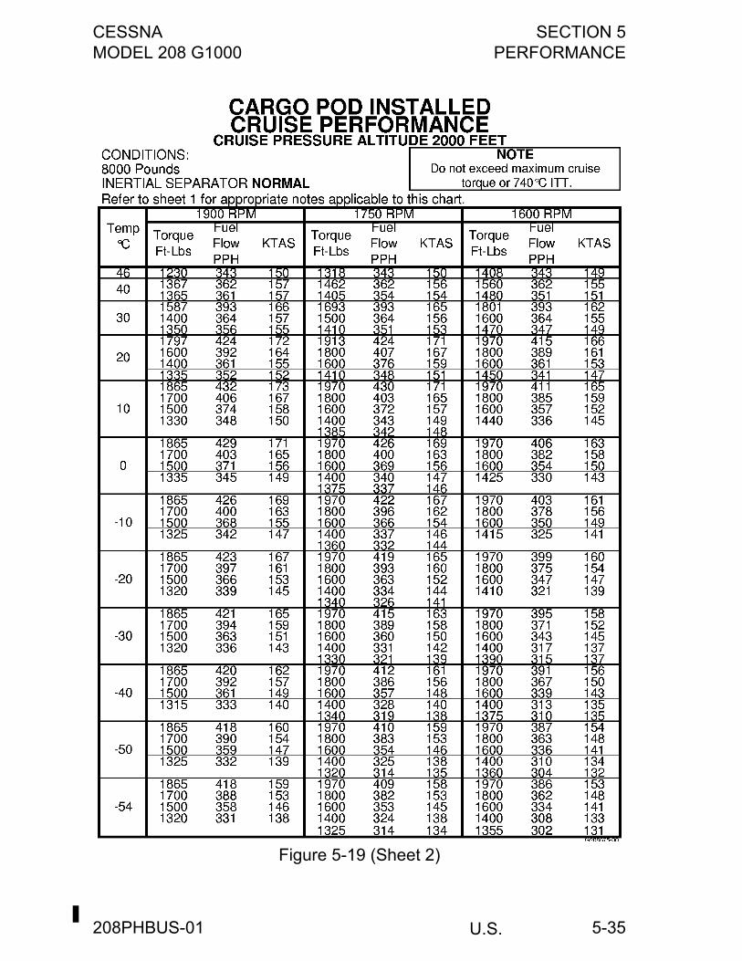
CESSNA SECTION 5MODEL 208 G1000 PERFORMANCE
U.S.
5-35
Figure 5-19 (Sheet 2)
208PHBUS-01
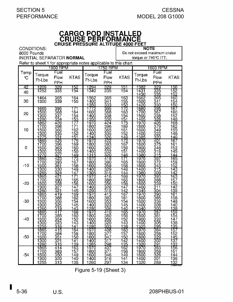
SECTION 5 CESSNAPERFORMANCE MODEL 208 G1000
U.S.5-36
Figure 5-19 (Sheet 3)
208PHBUS-01
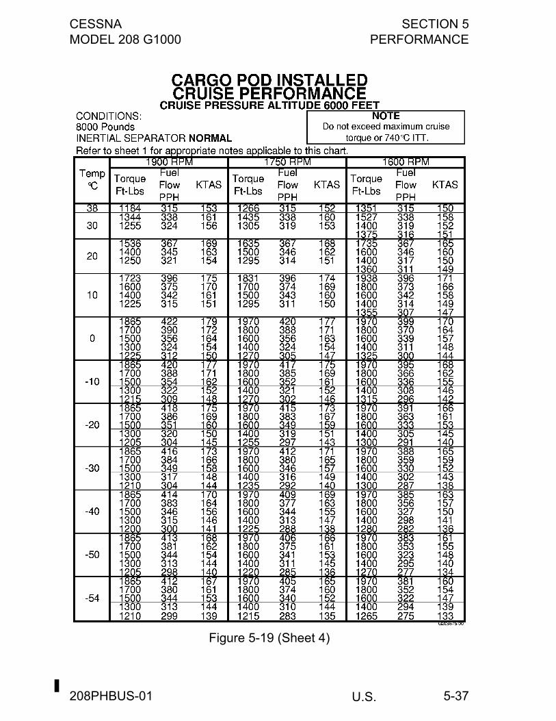
CESSNA SECTION 5MODEL 208 G1000 PERFORMANCE
U.S.
5-37
Figure 5-19 (Sheet 4)
208PHBUS-01
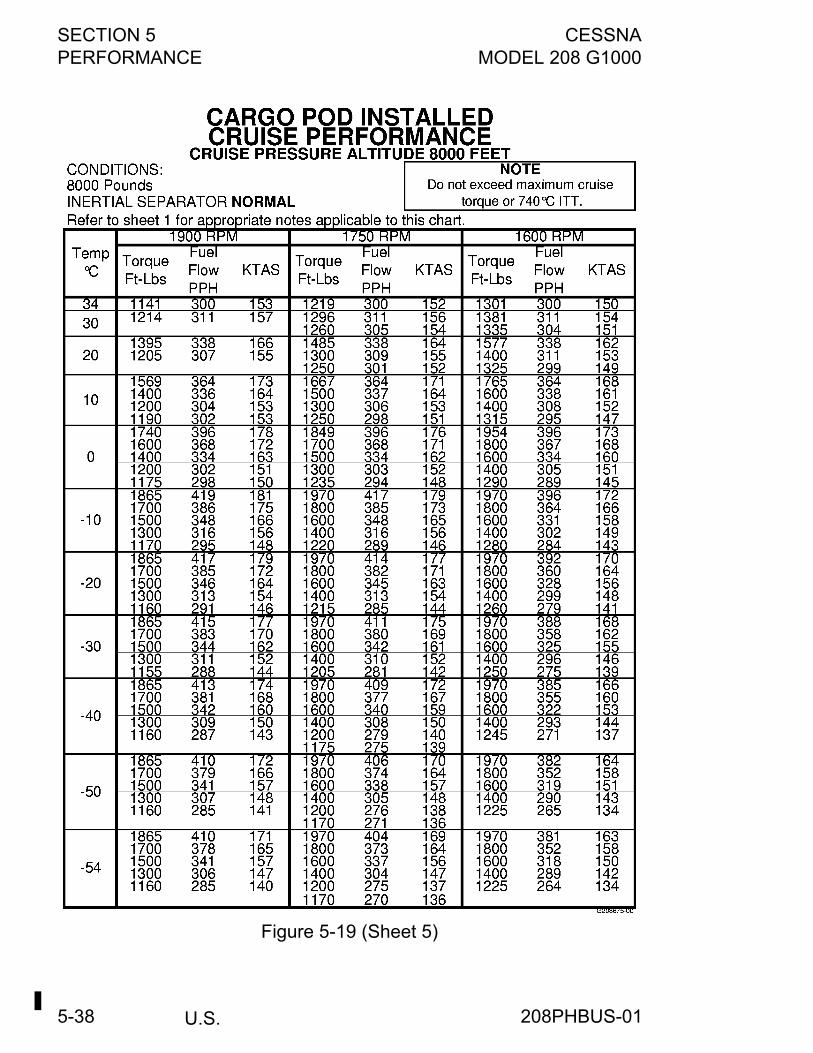
SECTION 5 CESSNAPERFORMANCE MODEL 208 G1000
U.S.5-38
Figure 5-19 (Sheet 5)
208PHBUS-01
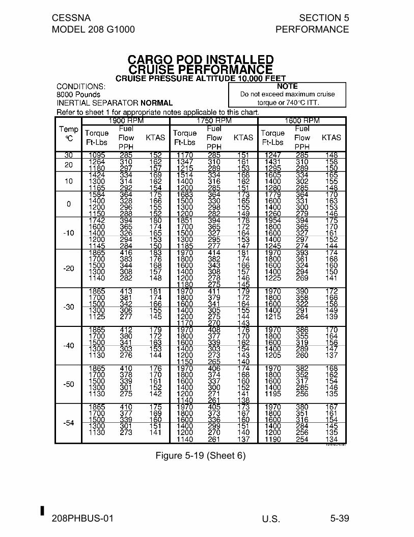
CESSNA SECTION 5MODEL 208 G1000 PERFORMANCE
U.S.
5-39
Figure 5-19 (Sheet 6)
208PHBUS-01
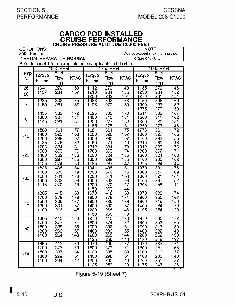
SECTION 5 CESSNAPERFORMANCE MODEL 208 G1000
U.S.5-40
Figure 5-19 (Sheet 7)
208PHBUS-01

CESSNA SECTION 5MODEL 208 G1000 PERFORMANCE
U.S.
5-41
Figure 5-19 (Sheet 8)
208PHBUS-01
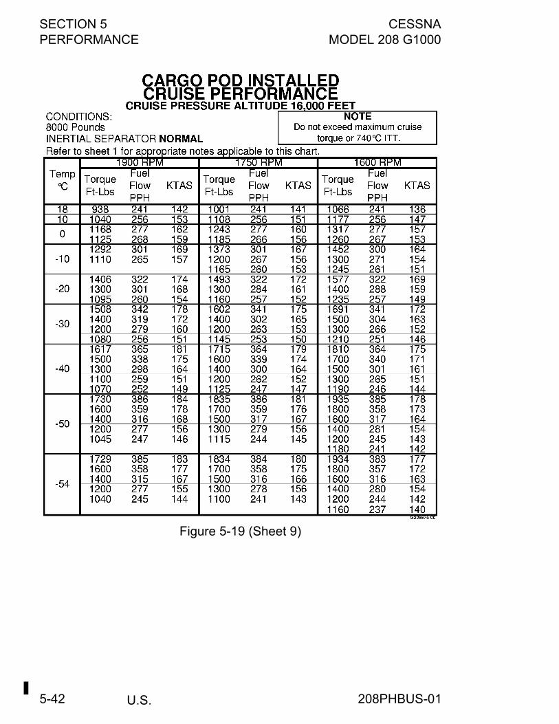
SECTION 5 CESSNAPERFORMANCE MODEL 208 G1000
U.S.5-42
Figure 5-19 (Sheet 9)
208PHBUS-01
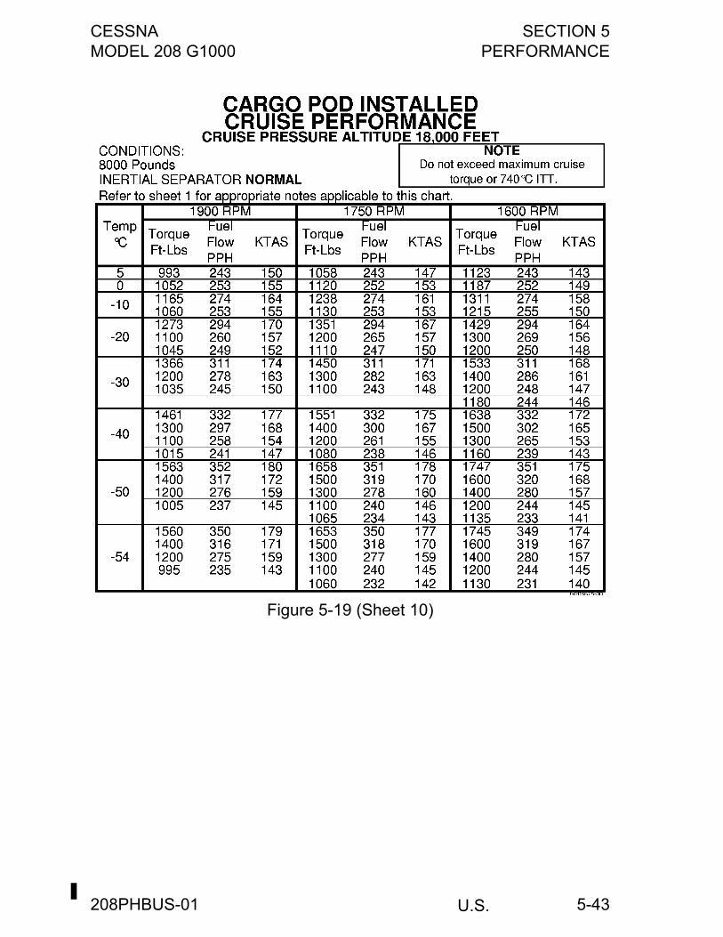
CESSNA SECTION 5MODEL 208 G1000 PERFORMANCE
U.S.
5-43
Figure 5-19 (Sheet 10)
208PHBUS-01
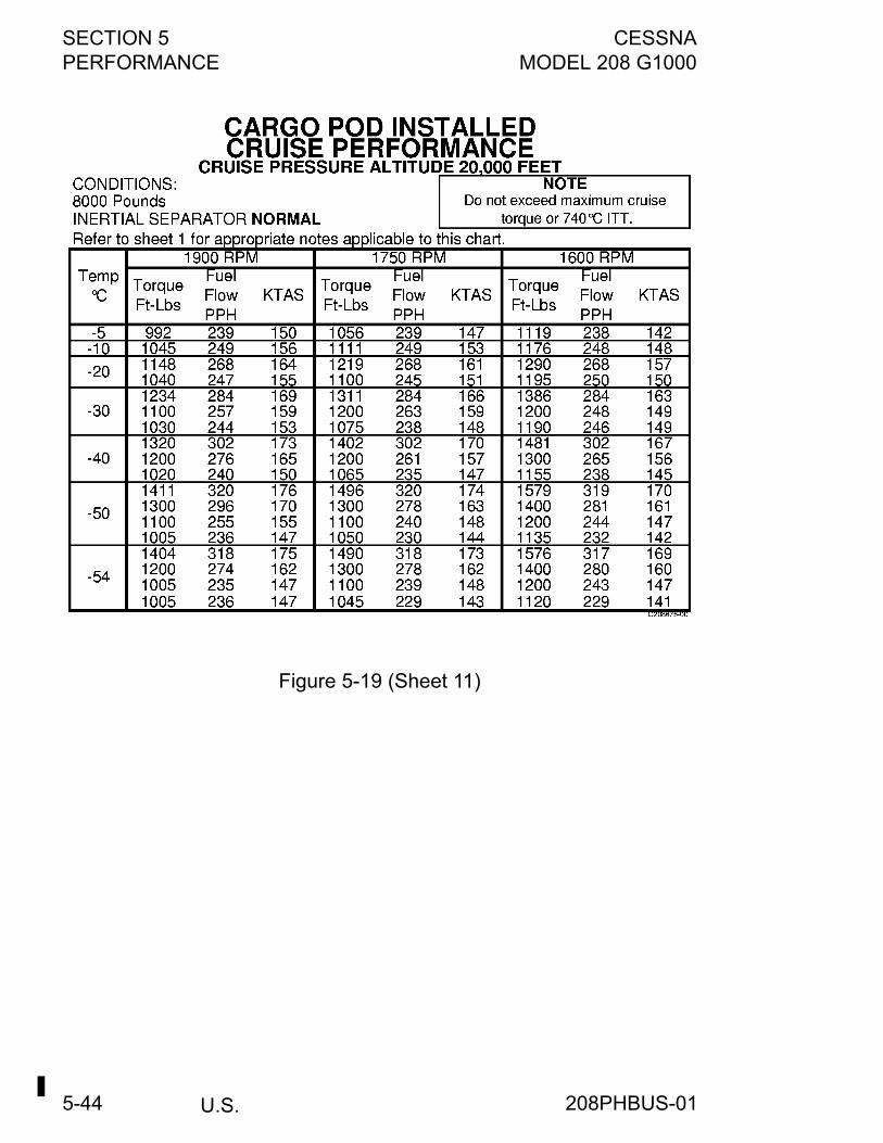
SECTION 5 CESSNAPERFORMANCE MODEL 208 G1000
U.S.5-44
Figure 5-19 (Sheet 11)
208PHBUS-01
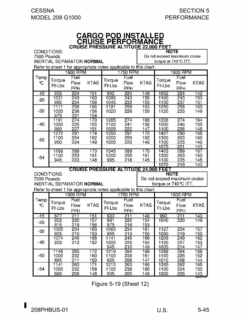
CESSNA SECTION 5MODEL 208 G1000 PERFORMANCE
U.S.
5-45
Figure 5-19 (Sheet 12)
208PHBUS-01
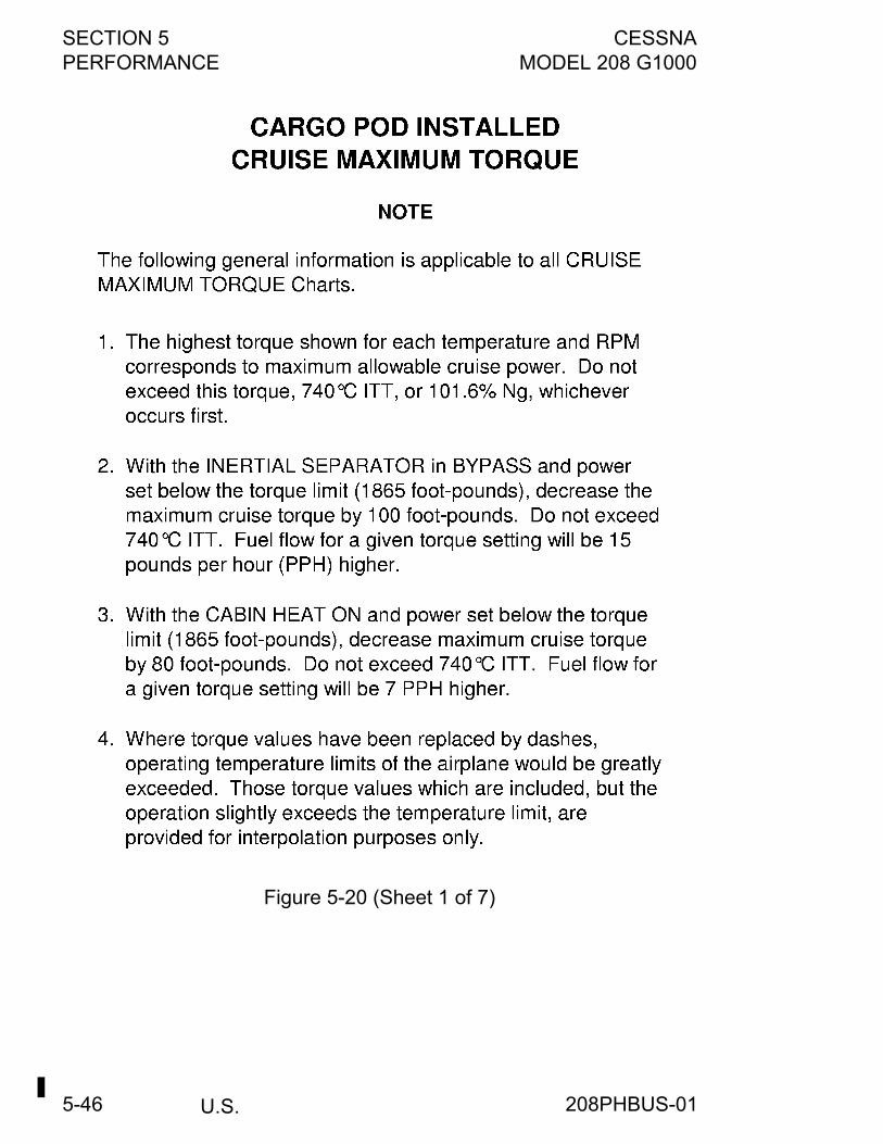
SECTION 5 CESSNAPERFORMANCE MODEL 208 G1000
U.S.5-46
Figure 5-20 (Sheet 1 of 7)
208PHBUS-01
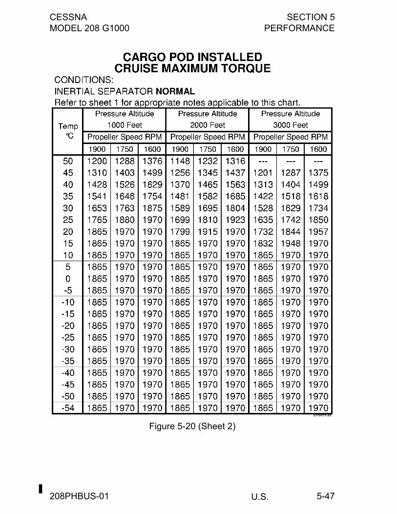
CESSNA SECTION 5MODEL 208 G1000 PERFORMANCE
U.S.
5-47
Figure 5-20 (Sheet 2)
208PHBUS-01
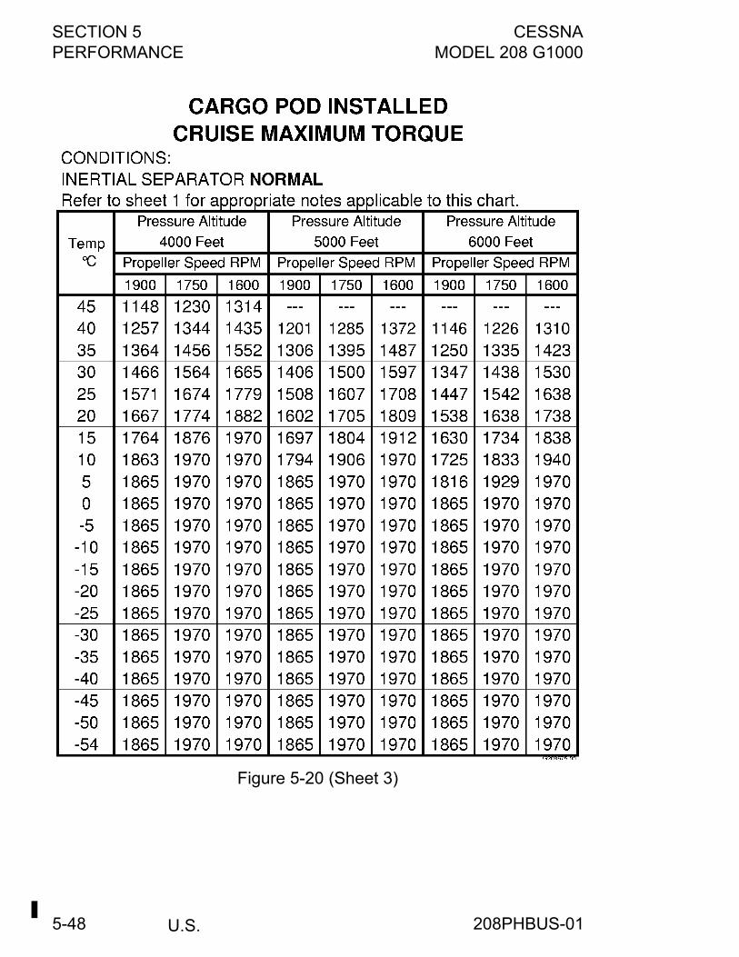
SECTION 5 CESSNAPERFORMANCE MODEL 208 G1000
U.S.5-48
Figure 5-20 (Sheet 3)
208PHBUS-01
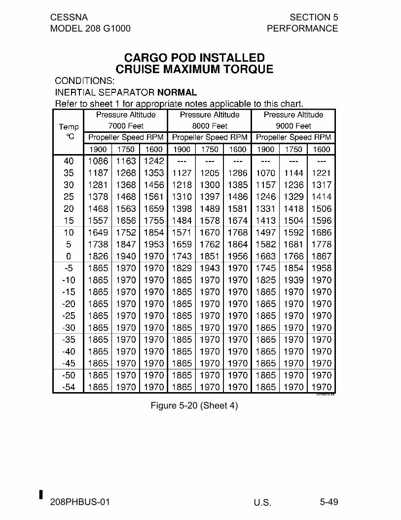
CESSNA SECTION 5MODEL 208 G1000 PERFORMANCE
U.S.
5-49
Figure 5-20 (Sheet 4)
208PHBUS-01
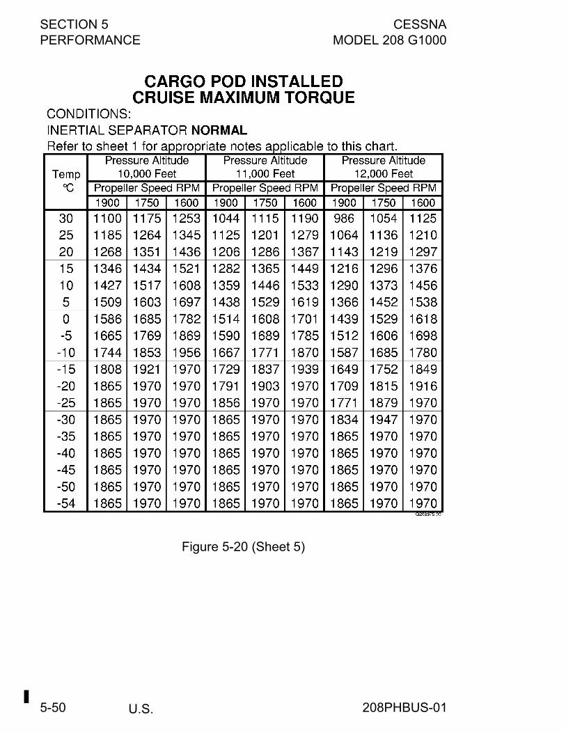
SECTION 5 CESSNAPERFORMANCE MODEL 208 G1000
U.S.5-50
Figure 5-20 (Sheet 5)
208PHBUS-01
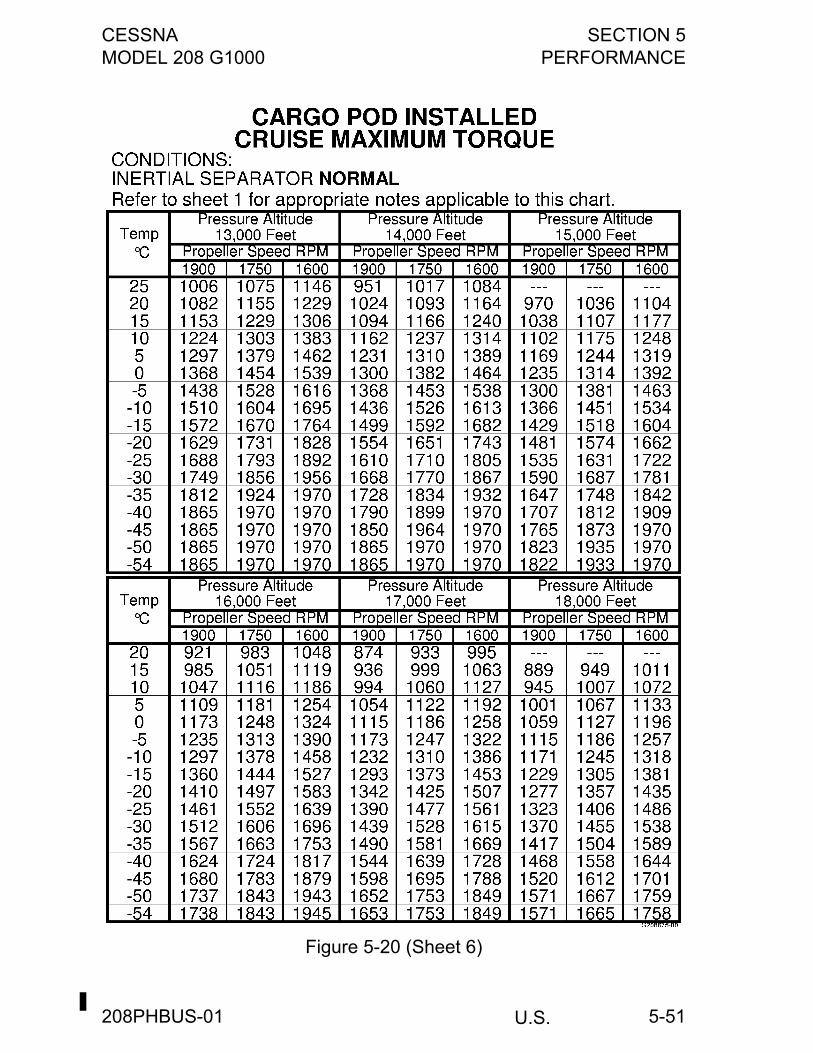
CESSNA SECTION 5MODEL 208 G1000 PERFORMANCE
U.S.
5-51
Figure 5-20 (Sheet 6)
208PHBUS-01
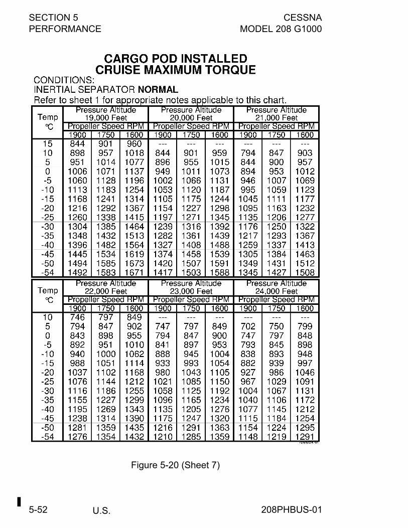
SECTION 5 CESSNAPERFORMANCE MODEL 208 G1000
U.S.5-52
Figure 5-20 (Sheet 7)
208PHBUS-01
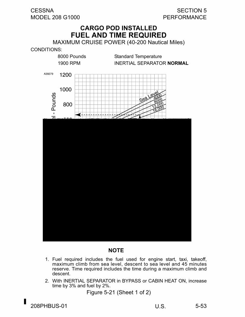
CESSNA SECTION 5MODEL 208 G1000 PERFORMANCE
U.S.
5-53
CARGO POD INSTALLEDFUEL AND TIME REQUIRED
MAXIMUM CRUISE POWER (40-200 Nautical Miles)CONDITIONS:
8000 Pounds Standard Temperature
1900 RPM INERTIAL SEPARATOR NORMAL
NOTE
1. Fuel required includes the fuel used for engine start, taxi, takeoff,maximum climb from sea level, descent to sea level and 45 minutesreserve. Time required includes the time during a maximum climb anddescent.
2. With INERTIAL SEPARATOR in BYPASS or CABIN HEAT ON, increasetime by 3% and fuel by 2%.
Figure 5-21 (Sheet 1 of 2)
208PHBUS-01
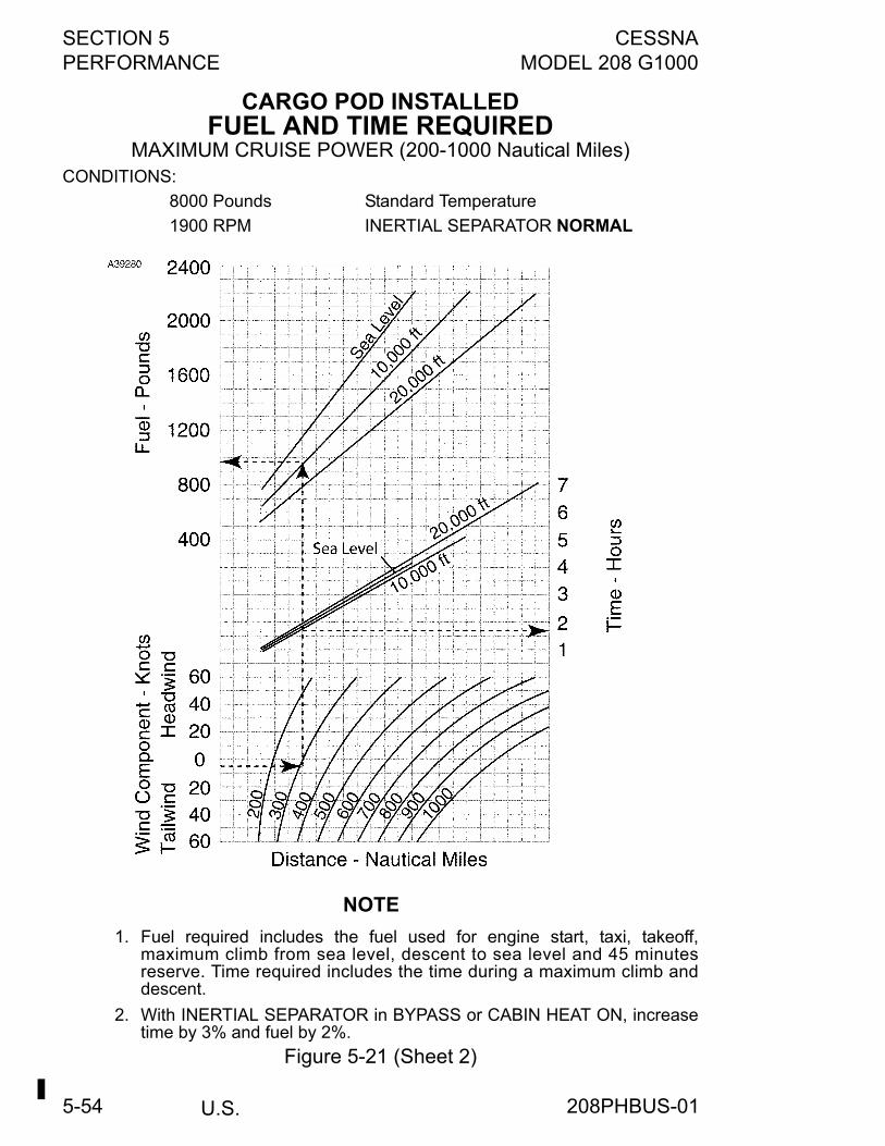
SECTION 5 CESSNAPERFORMANCE MODEL 208 G1000
U.S.5-54
CARGO POD INSTALLEDFUEL AND TIME REQUIRED
MAXIMUM CRUISE POWER (200-1000 Nautical Miles)CONDITIONS:
8000 Pounds Standard Temperature
1900 RPM INERTIAL SEPARATOR NORMAL
NOTE
1. Fuel required includes the fuel used for engine start, taxi, takeoff,maximum climb from sea level, descent to sea level and 45 minutesreserve. Time required includes the time during a maximum climb anddescent.
2. With INERTIAL SEPARATOR in BYPASS or CABIN HEAT ON, increasetime by 3% and fuel by 2%.
Figure 5-21 (Sheet 2)
208PHBUS-01
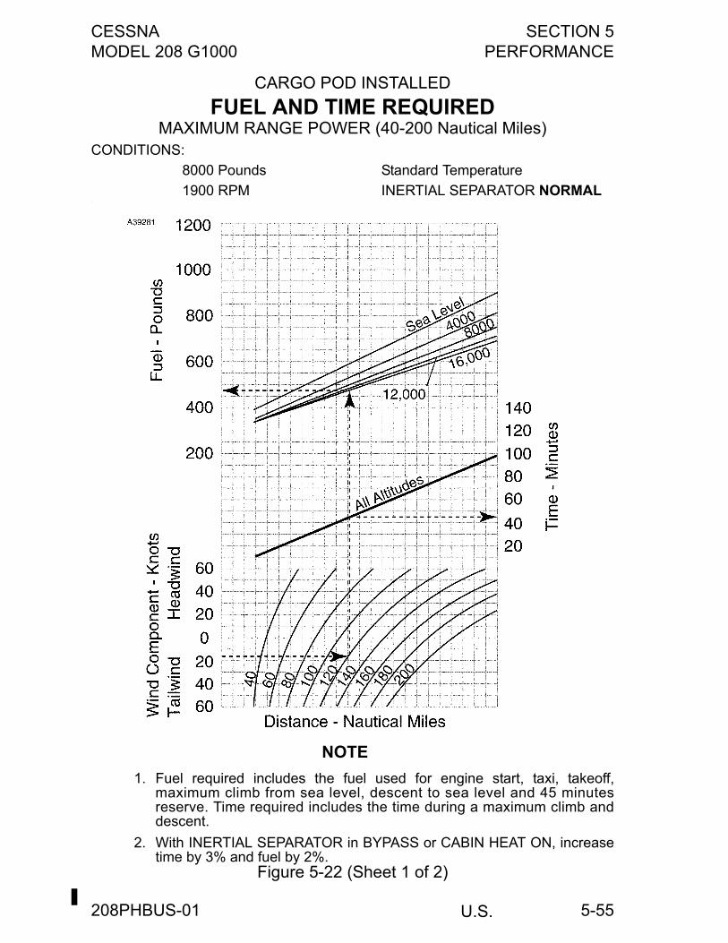
CESSNA SECTION 5MODEL 208 G1000 PERFORMANCE
U.S.
5-55
CARGO POD INSTALLED
FUEL AND TIME REQUIREDMAXIMUM RANGE POWER (40-200 Nautical Miles)
CONDITIONS:
8000 Pounds Standard Temperature
1900 RPM INERTIAL SEPARATOR NORMAL.
NOTE
1. Fuel required includes the fuel used for engine start, taxi, takeoff,maximum climb from sea level, descent to sea level and 45 minutesreserve. Time required includes the time during a maximum climb anddescent.
2. With INERTIAL SEPARATOR in BYPASS or CABIN HEAT ON, increasetime by 3% and fuel by 2%.
Figure 5-22 (Sheet 1 of 2)
208PHBUS-01
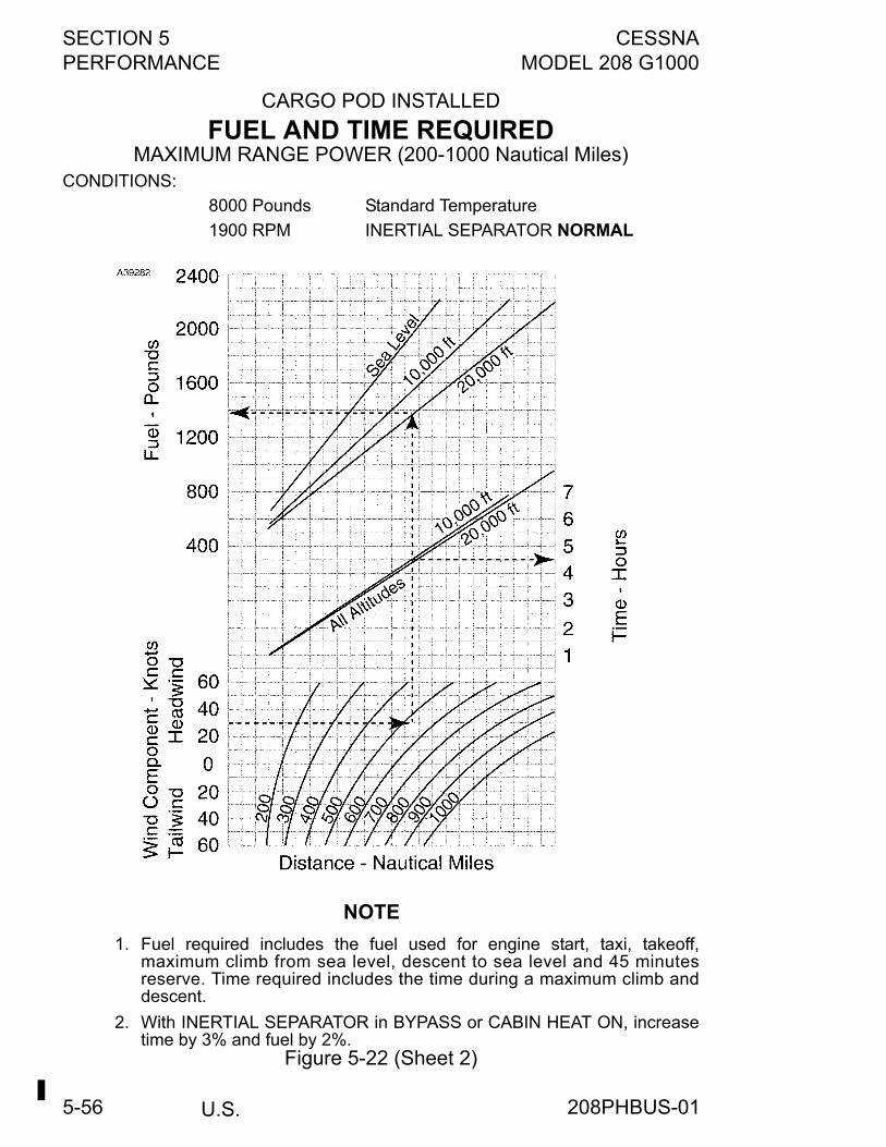
SECTION 5 CESSNAPERFORMANCE MODEL 208 G1000
U.S.5-56
CARGO POD INSTALLED
FUEL AND TIME REQUIREDMAXIMUM RANGE POWER (200-1000 Nautical Miles)
CONDITIONS:
8000 Pounds Standard Temperature
1900 RPM INERTIAL SEPARATOR NORMAL
NOTE
1. Fuel required includes the fuel used for engine start, taxi, takeoff,maximum climb from sea level, descent to sea level and 45 minutesreserve. Time required includes the time during a maximum climb anddescent.
2. With INERTIAL SEPARATOR in BYPASS or CABIN HEAT ON, increasetime by 3% and fuel by 2%.
Figure 5-22 (Sheet 2)
208PHBUS-01
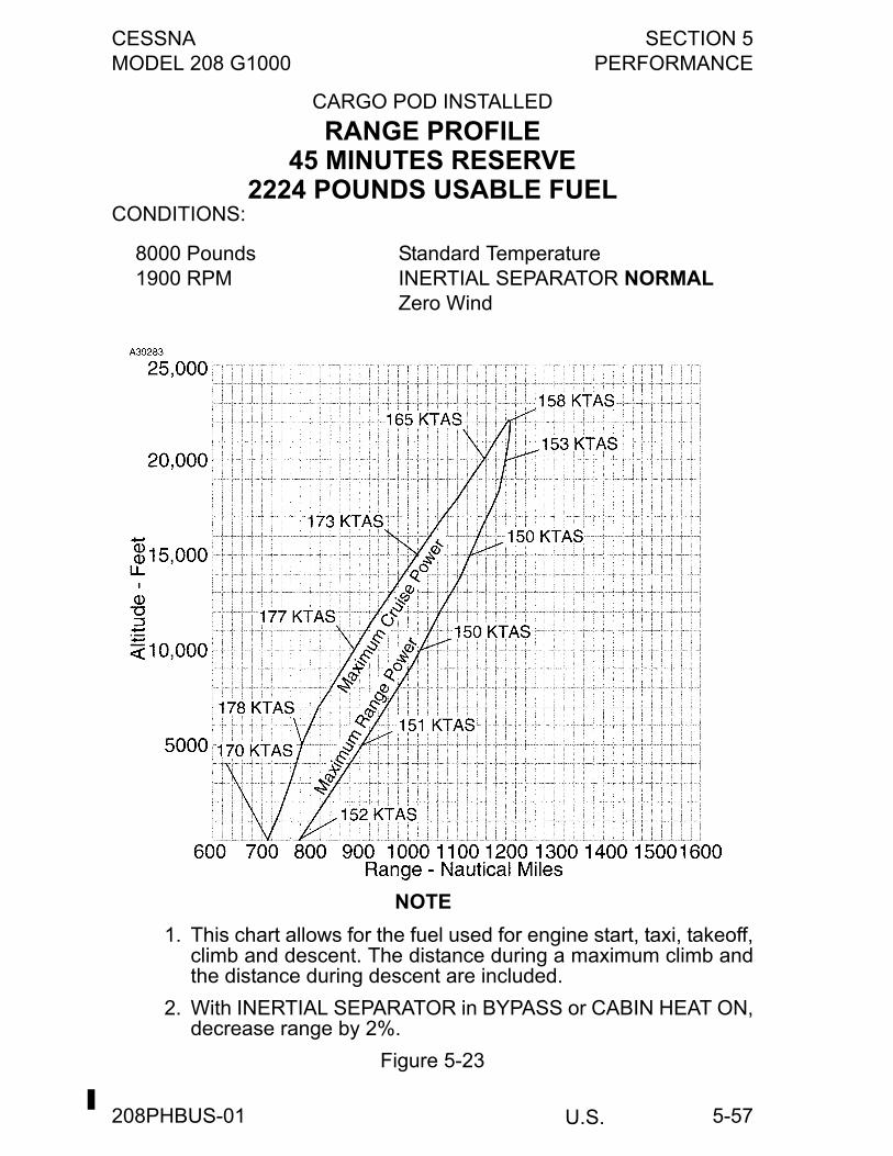
CESSNA SECTION 5MODEL 208 G1000 PERFORMANCE
U.S.
5-57
CARGO POD INSTALLED
RANGE PROFILE45 MINUTES RESERVE
2224 POUNDS USABLE FUELCONDITIONS:
.
NOTE
1. This chart allows for the fuel used for engine start, taxi, takeoff,climb and descent. The distance during a maximum climb andthe distance during descent are included.
2. With INERTIAL SEPARATOR in BYPASS or CABIN HEAT ON,decrease range by 2%.
Figure 5-23
8000 Pounds1900 RPM
Standard TemperatureINERTIAL SEPARATOR NORMALZero Wind
208PHBUS-01
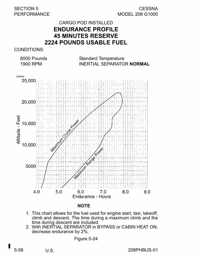
SECTION 5 CESSNAPERFORMANCE MODEL 208 G1000
U.S.5-58
CARGO POD INSTALLED
ENDURANCE PROFILE45 MINUTES RESERVE
2224 POUNDS USABLE FUELCONDITIONS:
NOTE
1. This chart allows for the fuel used for engine start, taxi, takeoff,climb and descent. The time during a maximum climb and thetime during descent are included.
2. With INERTIAL SEPARATOR in BYPASS or CABIN HEAT ON,decrease endurance by 2%.
Figure 5-24
8000 Pounds1900 RPM
Standard TemperatureINERTIAL SEPARATOR NORMAL
208PHBUS-01
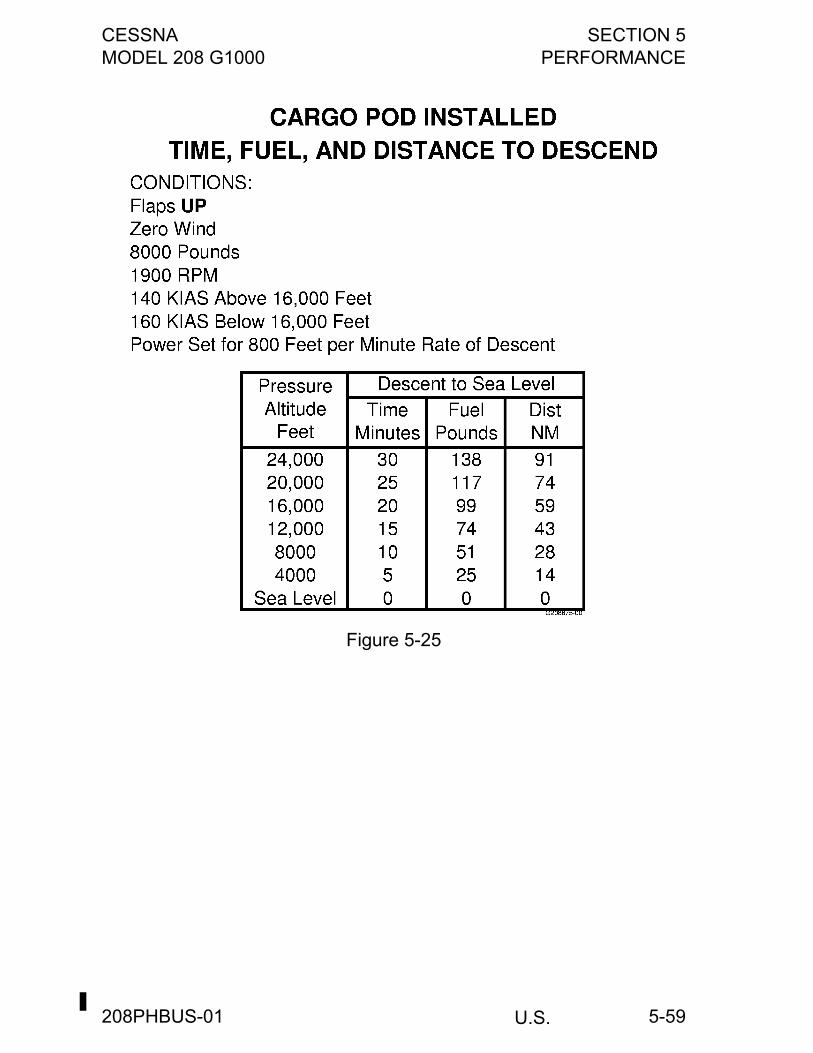
CESSNA SECTION 5MODEL 208 G1000 PERFORMANCE
U.S.
5-59
Figure 5-25
208PHBUS-01
SECTION 5 CESSNAPERFORMANCE MODEL 208 G1000
U.S.FAA APPROVED
5-60
Figure 5-26 (Sheet 1 of 4)
208PHBUS-00
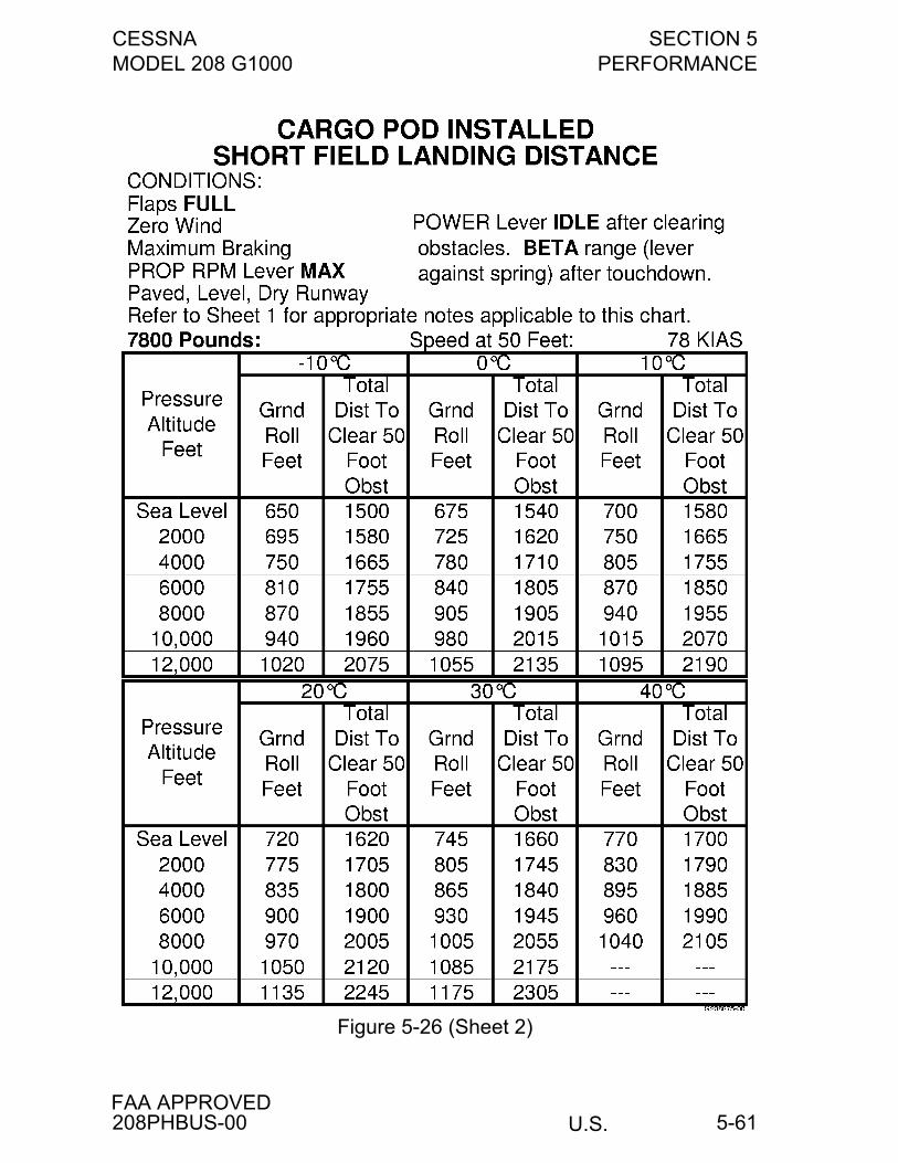
CESSNA SECTION 5MODEL 208 G1000 PERFORMANCE
U.S.FAA APPROVED
5-61
Figure 5-26 (Sheet 2)
208PHBUS-00
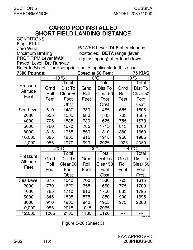
SECTION 5 CESSNAPERFORMANCE MODEL 208 G1000
U.S.FAA APPROVED
5-62
Figure 5-26 (Sheet 3)
208PHBUS-00

CESSNA SECTION 5MODEL 208 G1000 PERFORMANCE
U.S.FAA APPROVED
5-63
Figure 5-26 (Sheet 4)
208PHBUS-00
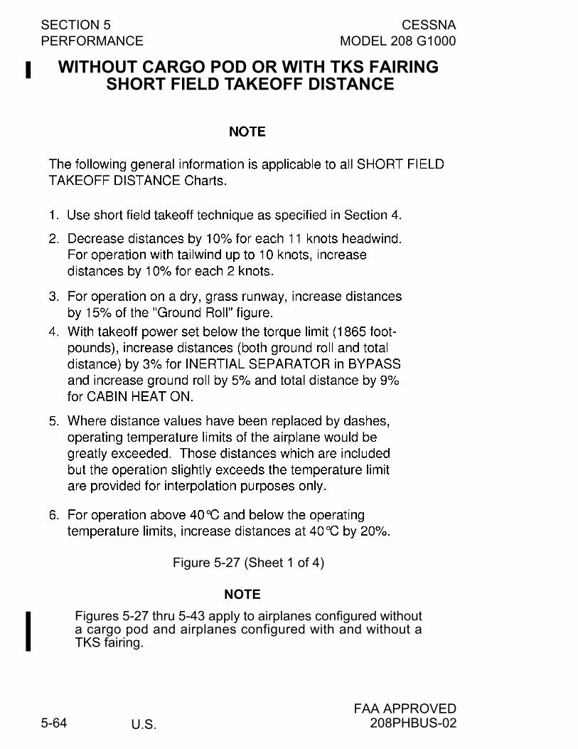
SECTION 5 CESSNAPERFORMANCE MODEL 208 G1000
U.S.FAA APPROVED
5-64
WITHOUT CARGO POD OR WITH TKS FAIRING SHORT FIELD TAKEOFF DISTANCE
Figure 5-27 (Sheet 1 of 4)
NOTE
Figures 5-27 thru 5-43 apply to airplanes configured withouta cargo pod and airplanes configured with and without aTKS fairing.
208PHBUS-02
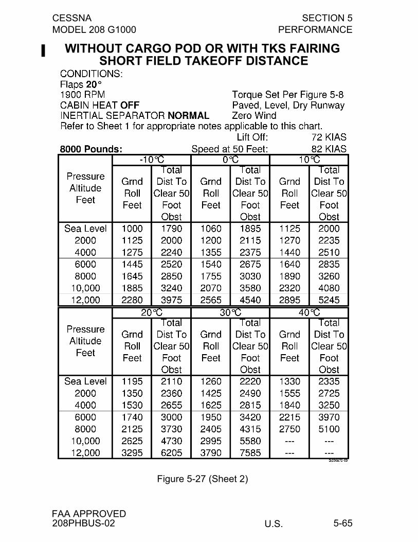
CESSNA SECTION 5MODEL 208 G1000 PERFORMANCE
U.S.FAA APPROVED
5-65
WITHOUT CARGO POD OR WITH TKS FAIRING SHORT FIELD TAKEOFF DISTANCE
Figure 5-27 (Sheet 2)
208PHBUS-02
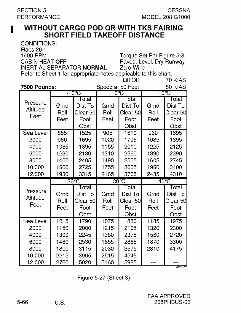
SECTION 5 CESSNAPERFORMANCE MODEL 208 G1000
U.S.FAA APPROVED
5-66
WITHOUT CARGO POD OR WITH TKS FAIRING SHORT FIELD TAKEOFF DISTANCE
Figure 5-27 (Sheet 3)
208PHBUS-02
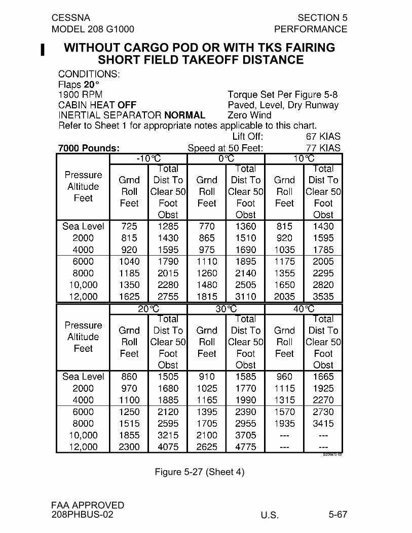
CESSNA SECTION 5MODEL 208 G1000 PERFORMANCE
U.S.FAA APPROVED
5-67
WITHOUT CARGO POD OR WITH TKS FAIRING SHORT FIELD TAKEOFF DISTANCE
Figure 5-27 (Sheet 4)
208PHBUS-02
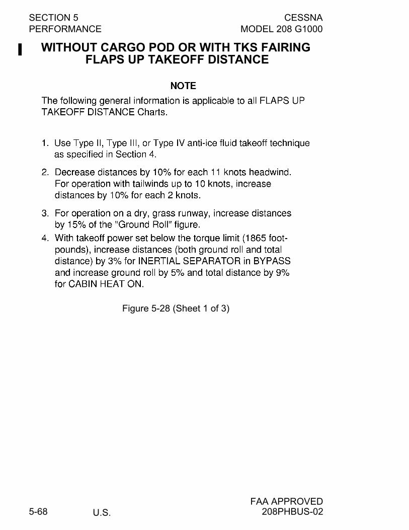
SECTION 5 CESSNAPERFORMANCE MODEL 208 G1000
U.S.FAA APPROVED
5-68
WITHOUT CARGO POD OR WITH TKS FAIRING FLAPS UP TAKEOFF DISTANCE
Figure 5-28 (Sheet 1 of 3)
208PHBUS-02
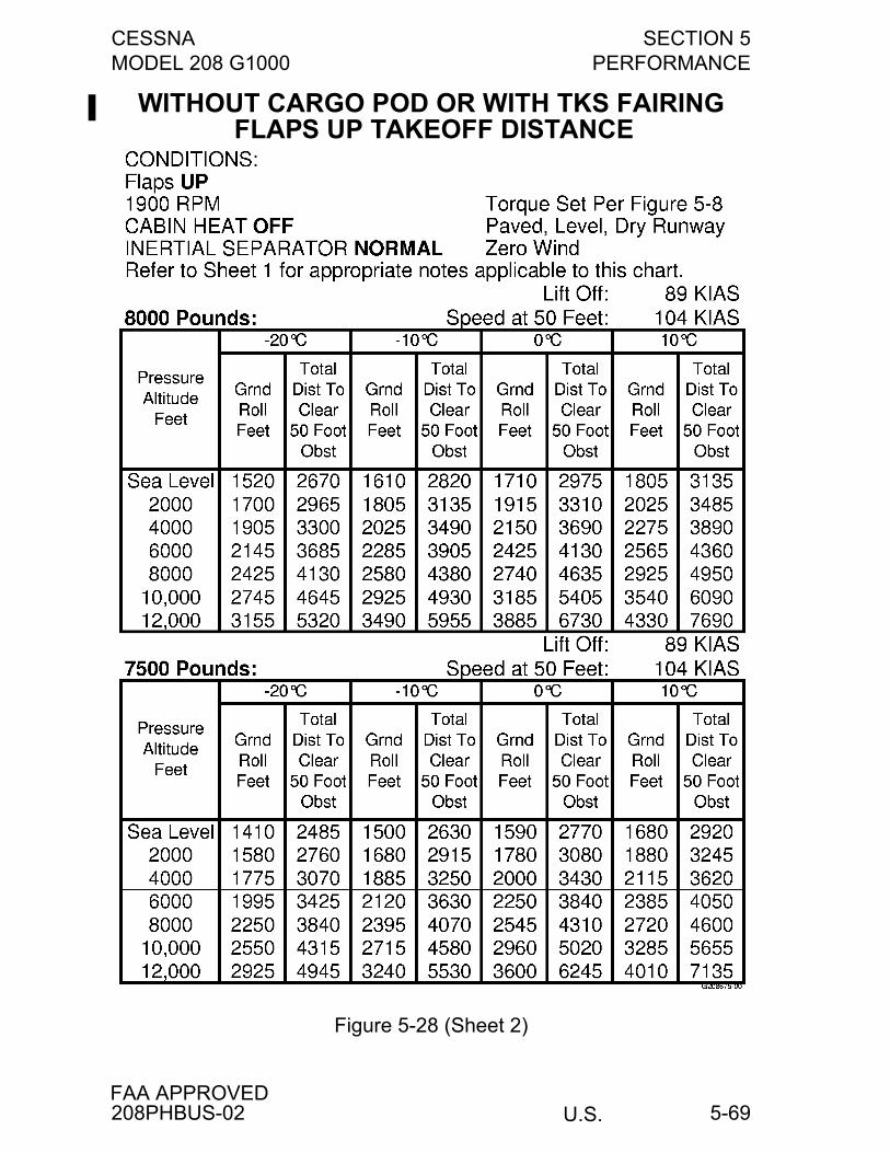
CESSNA SECTION 5MODEL 208 G1000 PERFORMANCE
U.S.FAA APPROVED
5-69
WITHOUT CARGO POD OR WITH TKS FAIRING FLAPS UP TAKEOFF DISTANCE
Figure 5-28 (Sheet 2)
208PHBUS-02
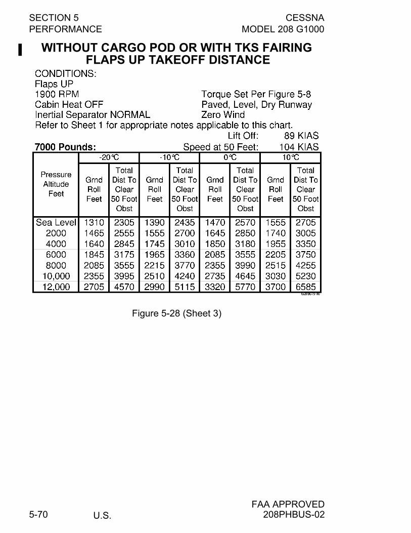
SECTION 5 CESSNAPERFORMANCE MODEL 208 G1000
U.S.FAA APPROVED
5-70
WITHOUT CARGO POD OR WITH TKS FAIRING FLAPS UP TAKEOFF DISTANCE
Figure 5-28 (Sheet 3)
208PHBUS-02

CESSNA SECTION 5MODEL 208 G1000 PERFORMANCE
U.S.FAA APPROVED
5-71
WITHOUT CARGO POD OR WITH TKS FAIRING RATE OF CLIMB - TAKEOFF FLAP SETTING
Figure 5-29
208PHBUS-02
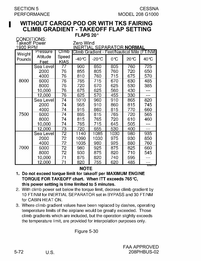
SECTION 5 CESSNAPERFORMANCE MODEL 208 G1000
U.S.FAA APPROVED
5-72
WITHOUT CARGO POD OR WITH TKS FAIRING CLIMB GRADIENT - TAKEOFF FLAP SETTING
Figure 5-30
208PHBUS-02
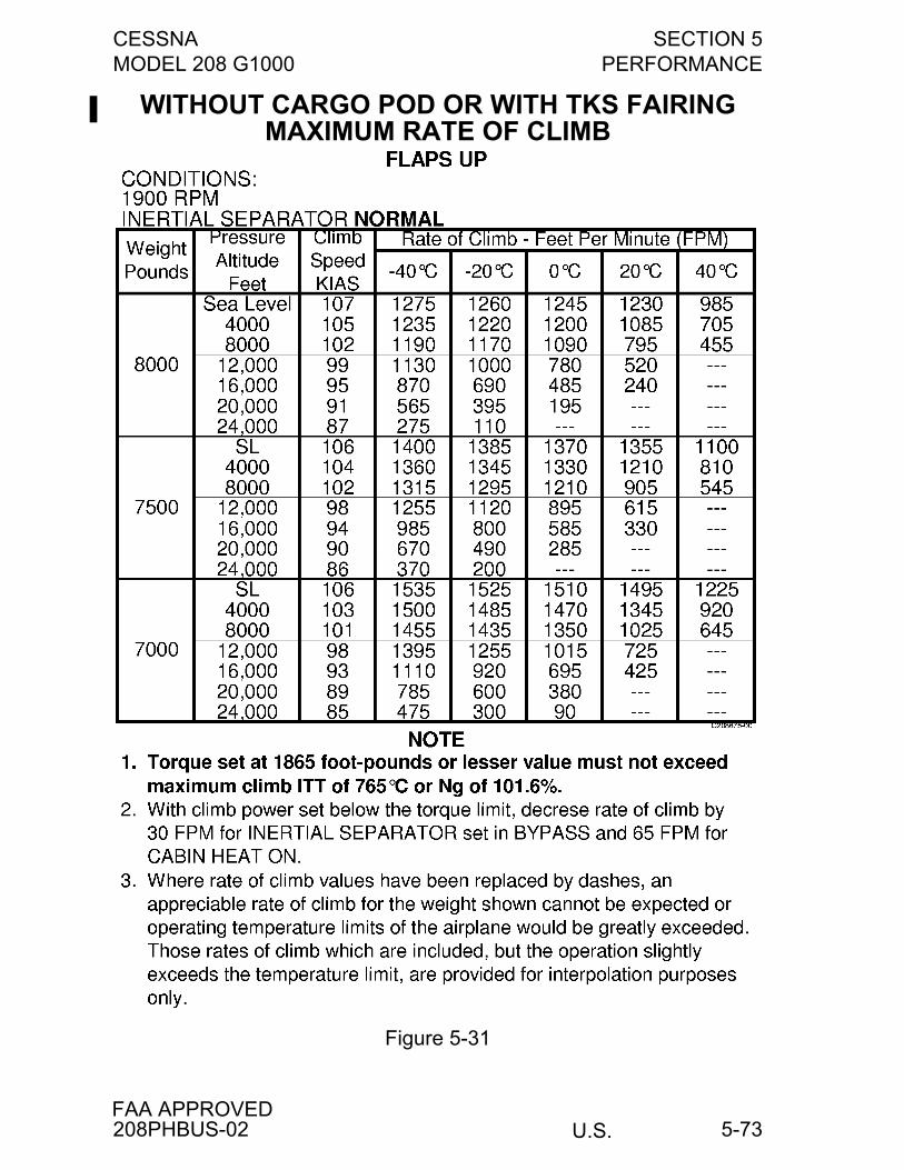
CESSNA SECTION 5MODEL 208 G1000 PERFORMANCE
U.S.FAA APPROVED
5-73
WITHOUT CARGO POD OR WITH TKS FAIRING MAXIMUM RATE OF CLIMB
Figure 5-31
208PHBUS-02
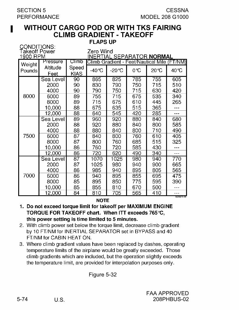
SECTION 5 CESSNAPERFORMANCE MODEL 208 G1000
U.S.FAA APPROVED
5-74
WITHOUT CARGO POD OR WITH TKS FAIRING CLIMB GRADIENT - TAKEOFF
Figure 5-32
208PHBUS-02
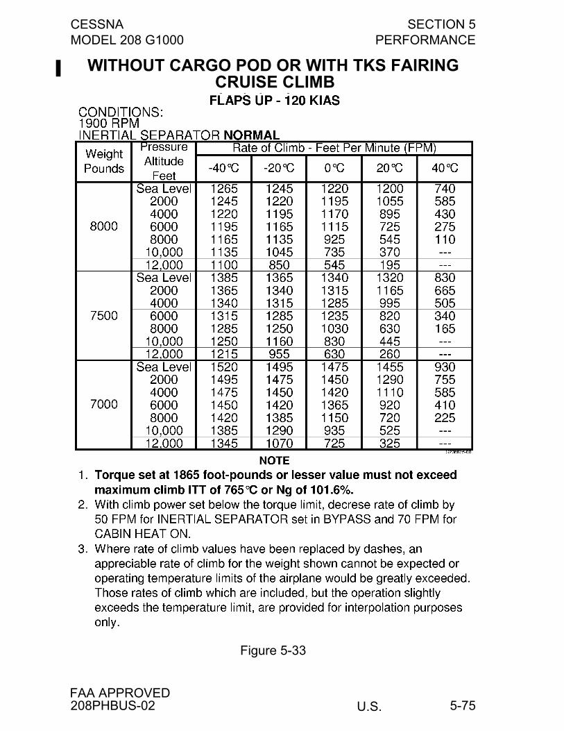
CESSNA SECTION 5MODEL 208 G1000 PERFORMANCE
U.S.FAA APPROVED
5-75
WITHOUT CARGO POD OR WITH TKS FAIRING CRUISE CLIMB
Figure 5-33
208PHBUS-02
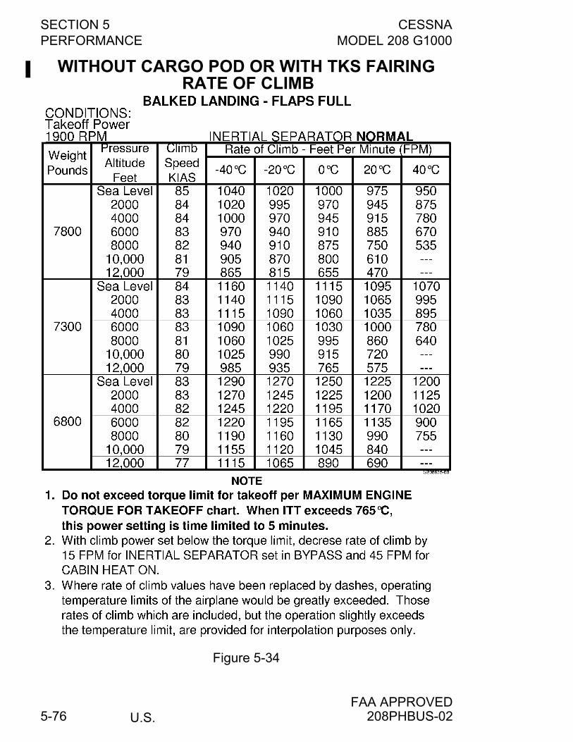
SECTION 5 CESSNAPERFORMANCE MODEL 208 G1000
U.S.FAA APPROVED
5-76
WITHOUT CARGO POD OR WITH TKS FAIRING RATE OF CLIMB
Figure 5-34
208PHBUS-02
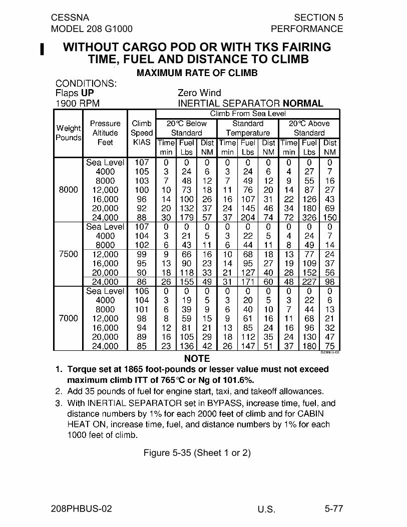
CESSNA SECTION 5MODEL 208 G1000 PERFORMANCE
U.S.
5-77
WITHOUT CARGO POD OR WITH TKS FAIRING TIME, FUEL AND DISTANCE TO CLIMB
Figure 5-35 (Sheet 1 or 2)
208PHBUS-02
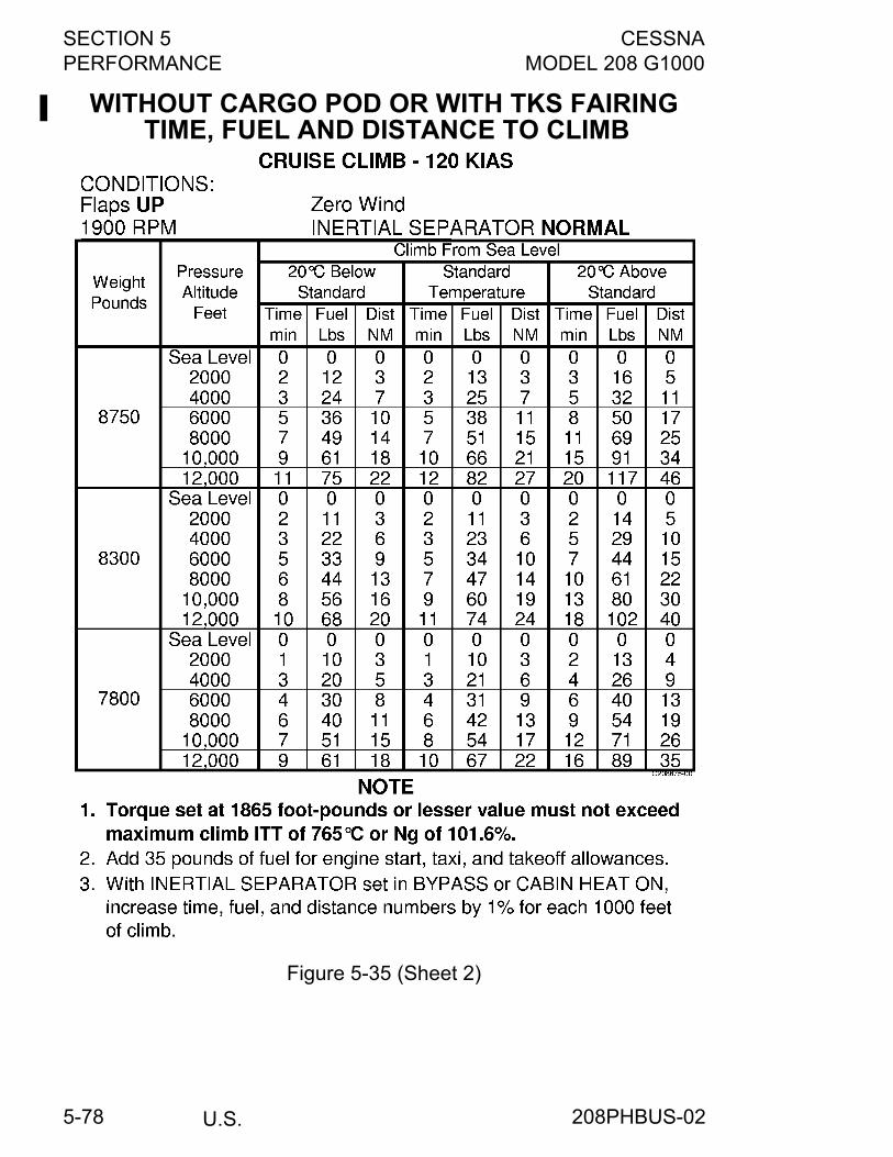
SECTION 5 CESSNAPERFORMANCE MODEL 208 G1000
U.S.5-78
WITHOUT CARGO POD OR WITH TKS FAIRING TIME, FUEL AND DISTANCE TO CLIMB
Figure 5-35 (Sheet 2)
208PHBUS-02
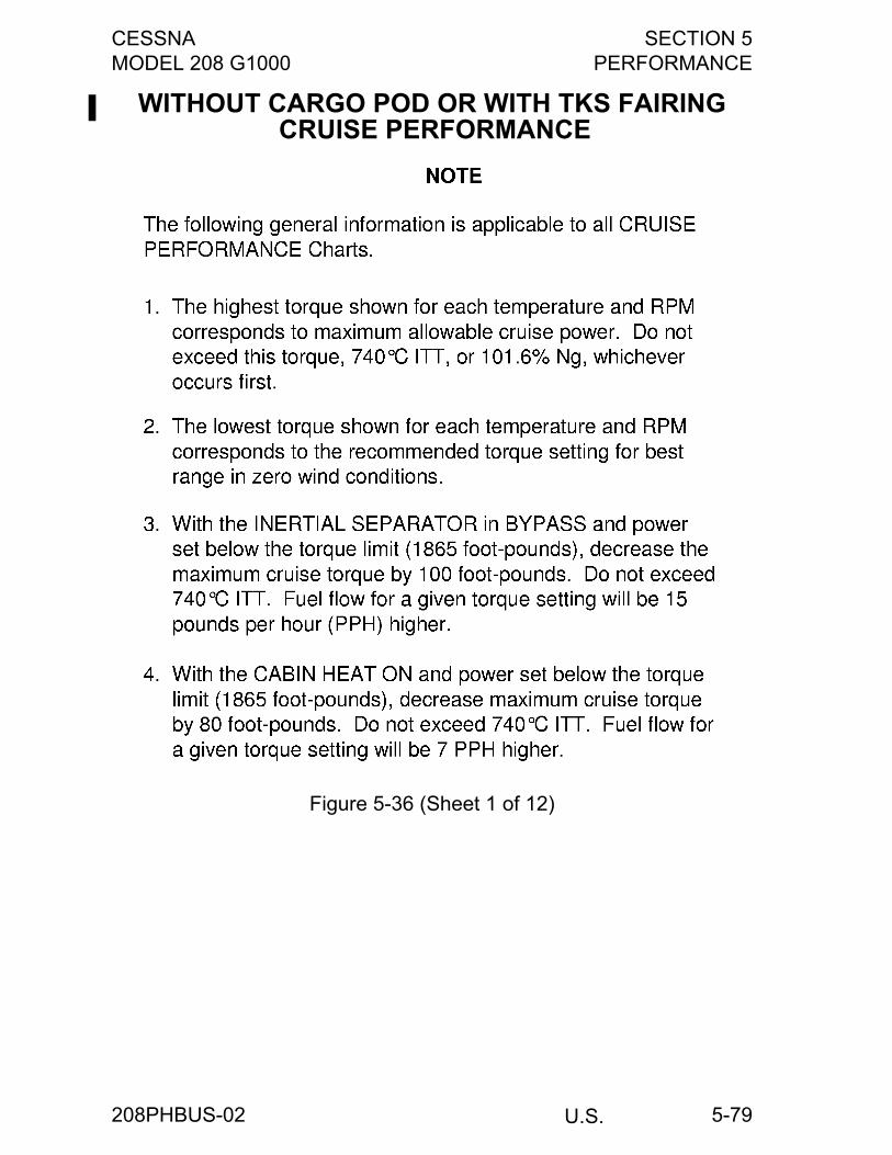
CESSNA SECTION 5MODEL 208 G1000 PERFORMANCE
U.S.
5-79
WITHOUT CARGO POD OR WITH TKS FAIRING CRUISE PERFORMANCE
Figure 5-36 (Sheet 1 of 12)
208PHBUS-02
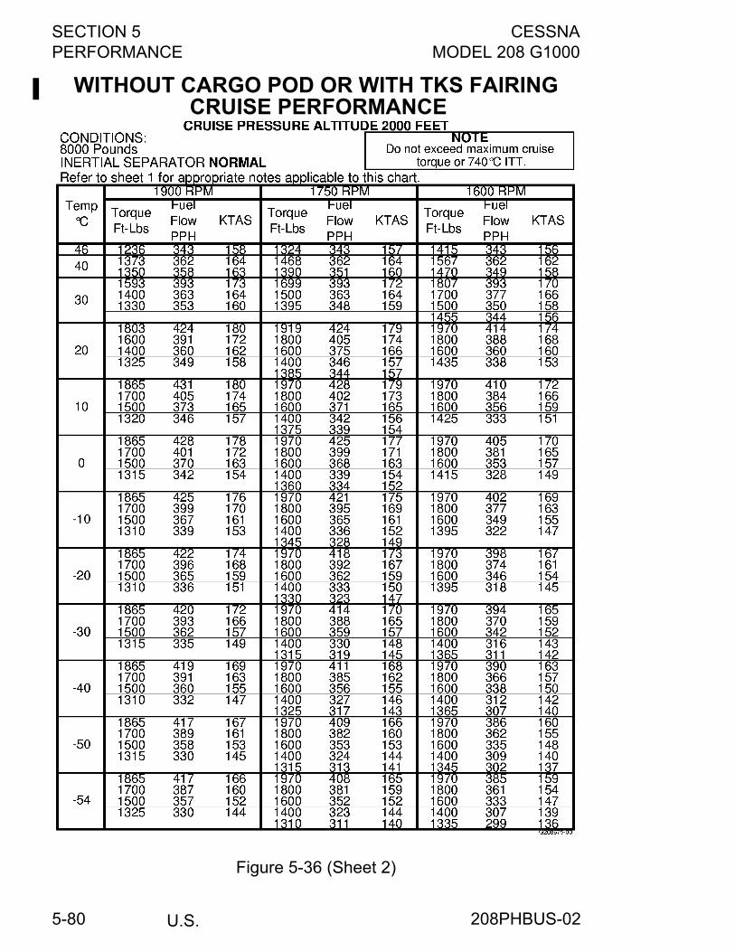
SECTION 5 CESSNAPERFORMANCE MODEL 208 G1000
U.S.5-80
WITHOUT CARGO POD OR WITH TKS FAIRING CRUISE PERFORMANCE
Figure 5-36 (Sheet 2)
208PHBUS-02
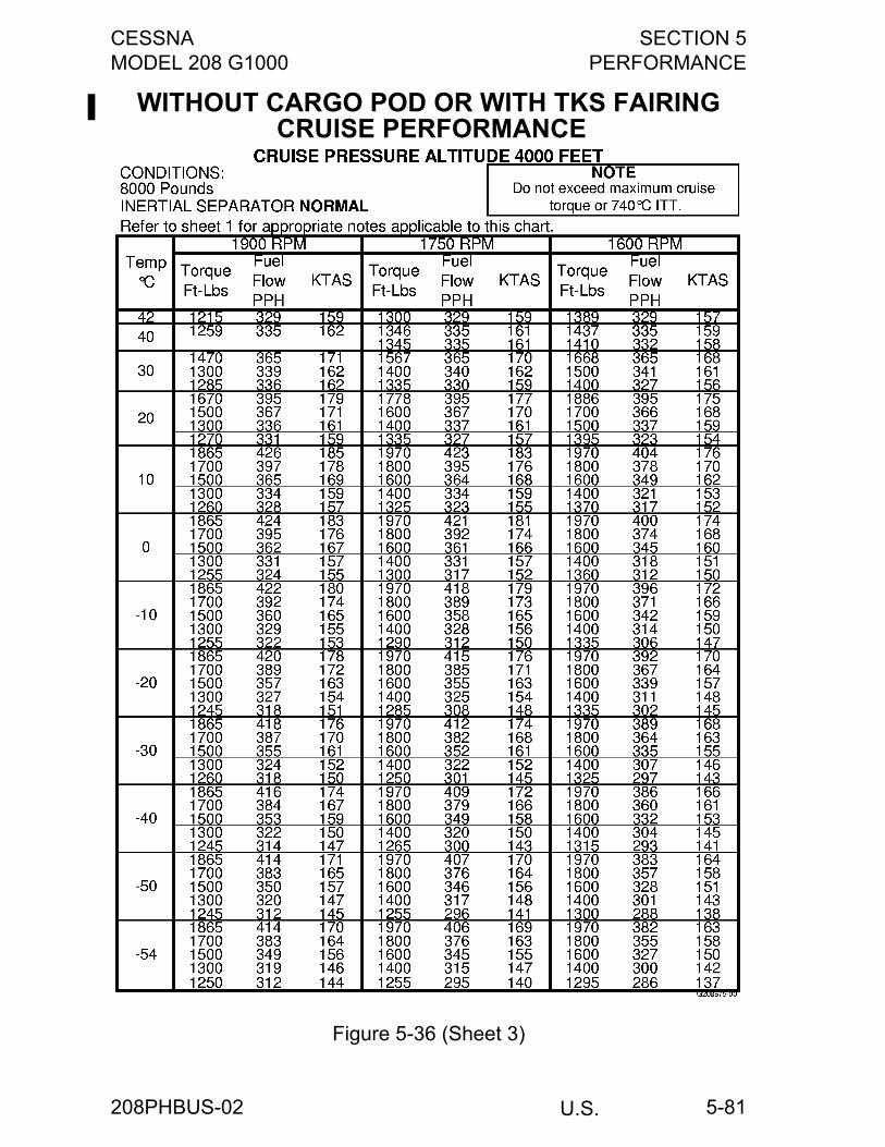
CESSNA SECTION 5MODEL 208 G1000 PERFORMANCE
U.S.
5-81
WITHOUT CARGO POD OR WITH TKS FAIRING CRUISE PERFORMANCE
Figure 5-36 (Sheet 3)
208PHBUS-02
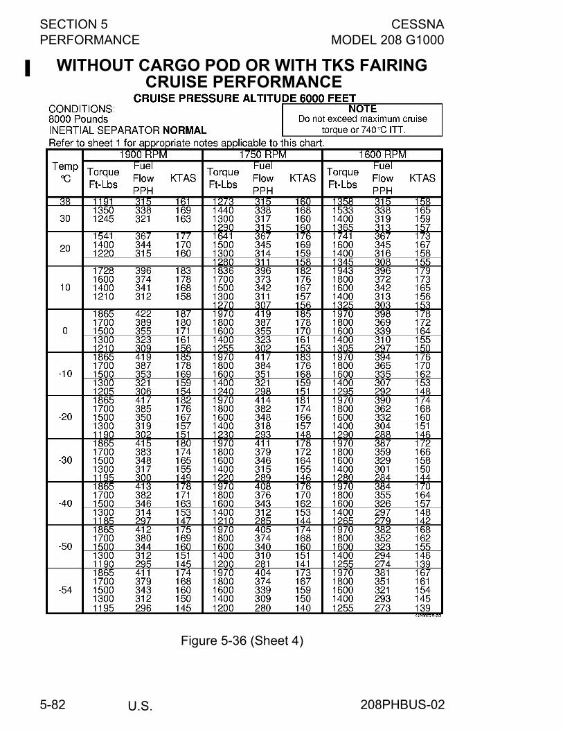
SECTION 5 CESSNAPERFORMANCE MODEL 208 G1000
U.S.5-82
WITHOUT CARGO POD OR WITH TKS FAIRING CRUISE PERFORMANCE
Figure 5-36 (Sheet 4)
208PHBUS-02

CESSNA SECTION 5MODEL 208 G1000 PERFORMANCE
U.S.
5-83
WITHOUT CARGO POD OR WITH TKS FAIRING CRUISE PERFORMANCE
Figure 5-36 (Sheet 5)
208PHBUS-02

SECTION 5 CESSNAPERFORMANCE MODEL 208 G1000
U.S.5-84
WITHOUT CARGO POD OR WITH TKS FAIRING CRUISE PERFORMANCE
Figure 5-36 (Sheet 6)
208PHBUS-02
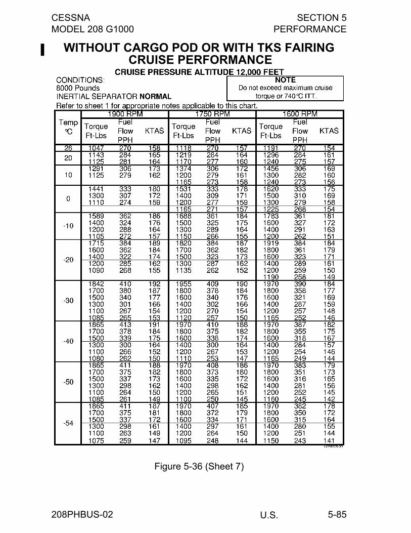
CESSNA SECTION 5MODEL 208 G1000 PERFORMANCE
U.S.
5-85
WITHOUT CARGO POD OR WITH TKS FAIRING CRUISE PERFORMANCE
Figure 5-36 (Sheet 7)
208PHBUS-02
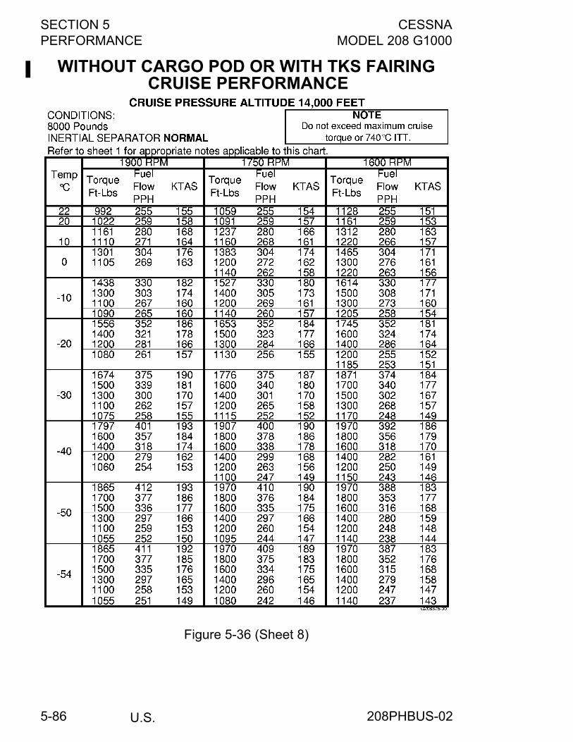
SECTION 5 CESSNAPERFORMANCE MODEL 208 G1000
U.S.5-86
WITHOUT CARGO POD OR WITH TKS FAIRING CRUISE PERFORMANCE
Figure 5-36 (Sheet 8)
208PHBUS-02
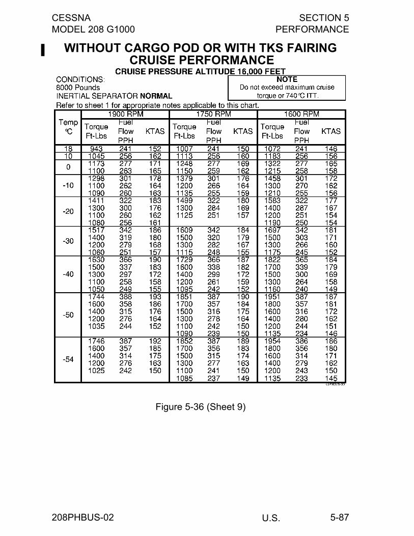
CESSNA SECTION 5MODEL 208 G1000 PERFORMANCE
U.S.
5-87
WITHOUT CARGO POD OR WITH TKS FAIRING CRUISE PERFORMANCE
Figure 5-36 (Sheet 9)
208PHBUS-02
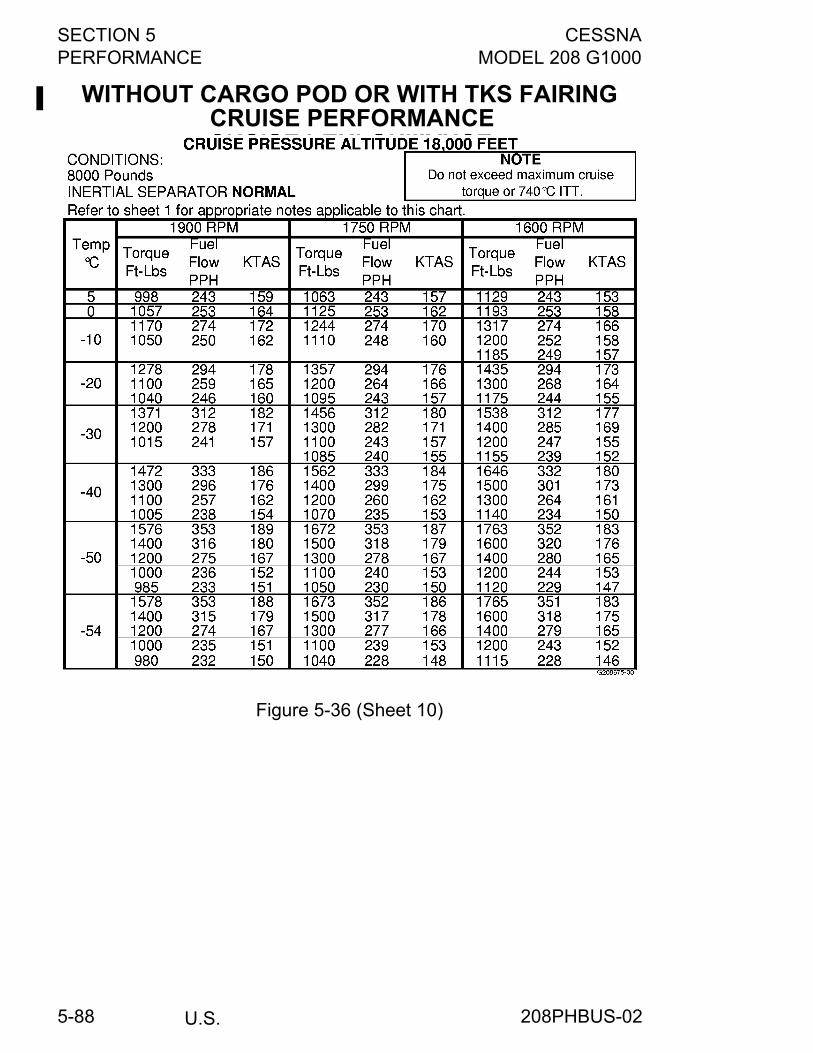
SECTION 5 CESSNAPERFORMANCE MODEL 208 G1000
U.S.5-88
WITHOUT CARGO POD OR WITH TKS FAIRING CRUISE PERFORMANCE
Figure 5-36 (Sheet 10)
208PHBUS-02
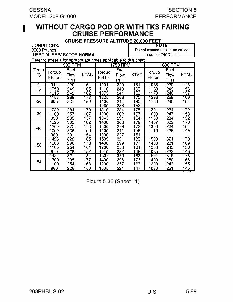
CESSNA SECTION 5MODEL 208 G1000 PERFORMANCE
U.S.
5-89
WITHOUT CARGO POD OR WITH TKS FAIRINGCRUISE PERFORMANCE
Figure 5-36 (Sheet 11)
208PHBUS-02
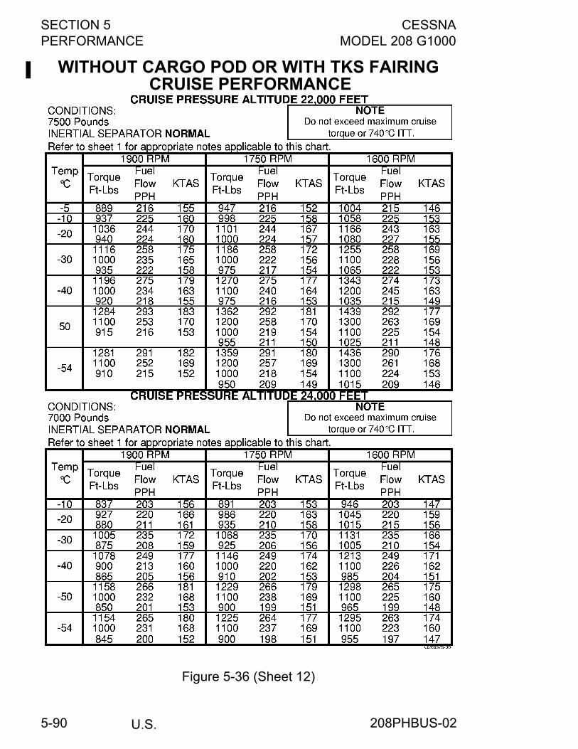
SECTION 5 CESSNAPERFORMANCE MODEL 208 G1000
U.S.5-90
WITHOUT CARGO POD OR WITH TKS FAIRING CRUISE PERFORMANCE
Figure 5-36 (Sheet 12)
208PHBUS-02
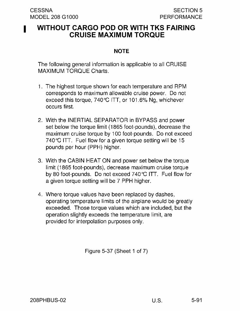
CESSNA SECTION 5MODEL 208 G1000 PERFORMANCE
U.S.
5-91
WITHOUT CARGO POD OR WITH TKS FAIRING CRUISE MAXIMUM TORQUE
Figure 5-37 (Sheet 1 of 7)
208PHBUS-02

SECTION 5 CESSNAPERFORMANCE MODEL 208 G1000
U.S.5-92
WITHOUT CARGO POD OR WITH TKS FAIRING CRUISE MAXIMUM TORQUE
Figure 5-37 (Sheet 2)
208PHBUS-02

CESSNA SECTION 5MODEL 208 G1000 PERFORMANCE
U.S.
5-93
WITHOUT CARGO POD OR WITH TKS FAIRING CRUISE MAXIMUM TORQUE
Figure 5-37 (Sheet 3)
208PHBUS-02
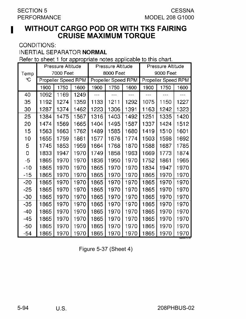
SECTION 5 CESSNAPERFORMANCE MODEL 208 G1000
U.S.5-94
WITHOUT CARGO POD OR WITH TKS FAIRING CRUISE MAXIMUM TORQUE
Figure 5-37 (Sheet 4)
208PHBUS-02
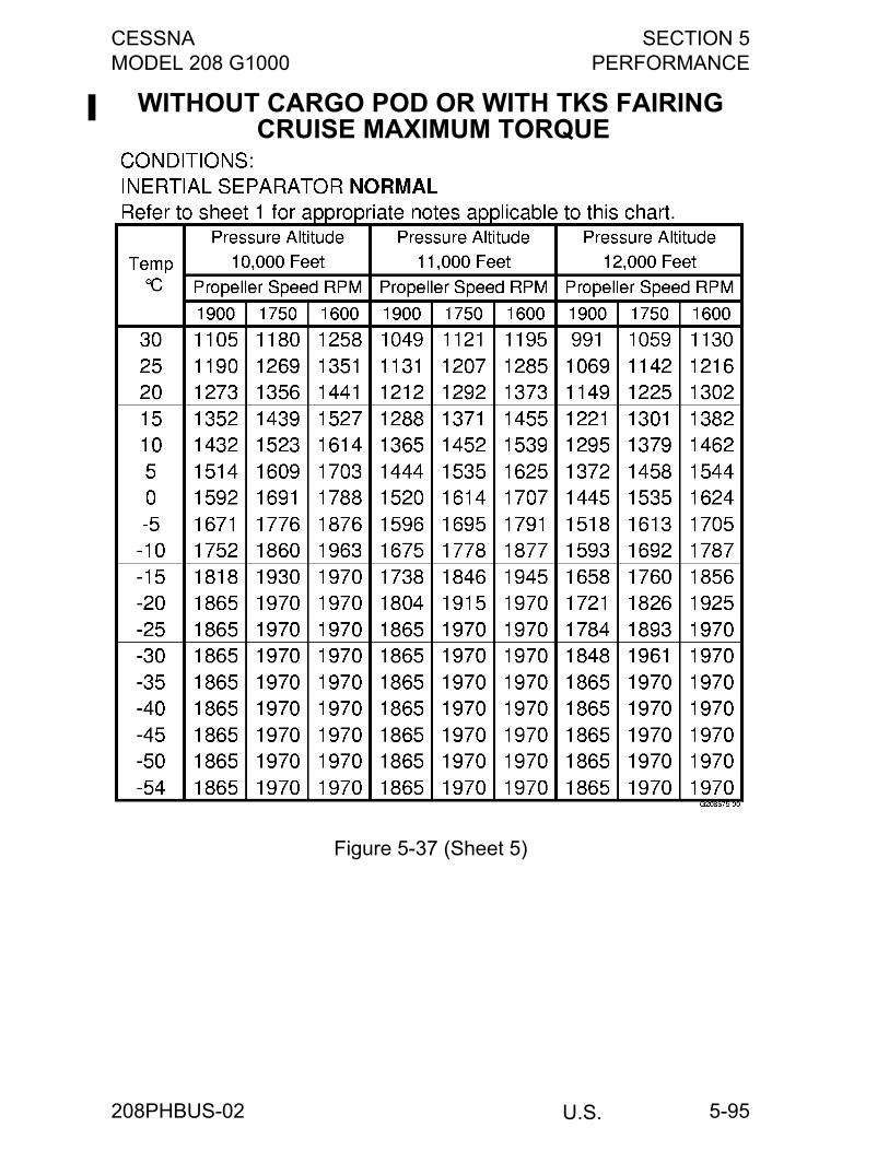
CESSNA SECTION 5MODEL 208 G1000 PERFORMANCE
U.S.
5-95
WITHOUT CARGO POD OR WITH TKS FAIRING CRUISE MAXIMUM TORQUE
Figure 5-37 (Sheet 5)
208PHBUS-02
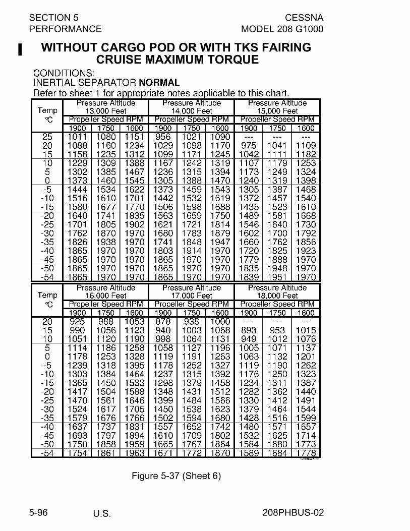
SECTION 5 CESSNAPERFORMANCE MODEL 208 G1000
U.S.5-96
WITHOUT CARGO POD OR WITH TKS FAIRING CRUISE MAXIMUM TORQUE
Figure 5-37 (Sheet 6)
208PHBUS-02
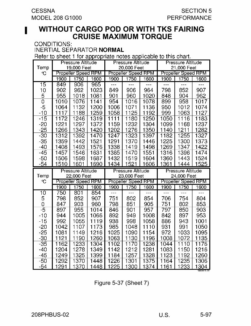
CESSNA SECTION 5MODEL 208 G1000 PERFORMANCE
U.S.
5-97
WITHOUT CARGO POD OR WITH TKS FAIRING CRUISE MAXIMUM TORQUE
Figure 5-37 (Sheet 7)
208PHBUS-02
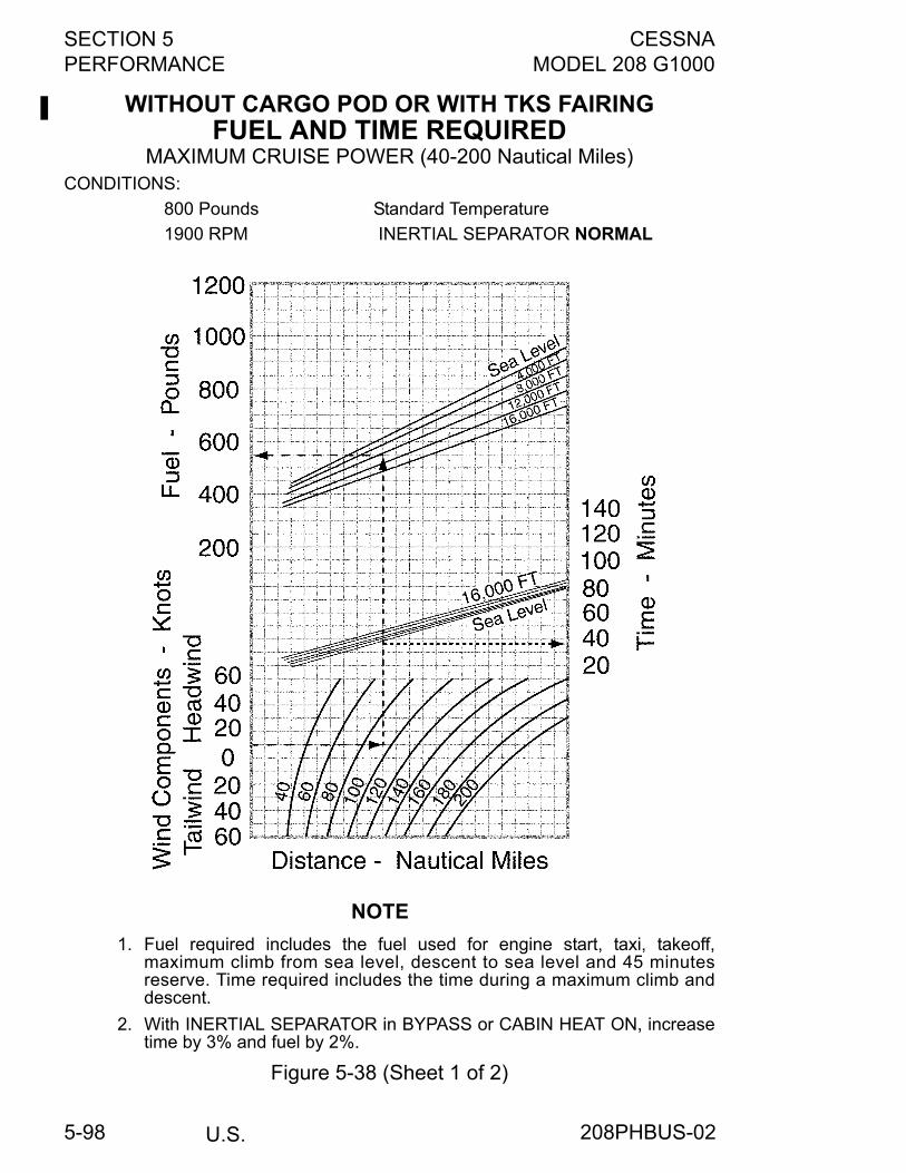
SECTION 5 CESSNAPERFORMANCE MODEL 208 G1000
U.S.5-98
WITHOUT CARGO POD OR WITH TKS FAIRINGFUEL AND TIME REQUIRED
MAXIMUM CRUISE POWER (40-200 Nautical Miles)CONDITIONS:
800 Pounds Standard Temperature
1900 RPM INERTIAL SEPARATOR NORMAL
NOTE
1. Fuel required includes the fuel used for engine start, taxi, takeoff,maximum climb from sea level, descent to sea level and 45 minutesreserve. Time required includes the time during a maximum climb anddescent.
2. With INERTIAL SEPARATOR in BYPASS or CABIN HEAT ON, increasetime by 3% and fuel by 2%.
Figure 5-38 (Sheet 1 of 2)
208PHBUS-02
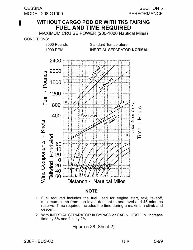
CESSNA SECTION 5MODEL 208 G1000 PERFORMANCE
U.S.
5-99
WITHOUT CARGO POD OR WITH TKS FAIRINGFUEL AND TIME REQUIRED
MAXIMUM CRUISE POWER (200-1000 Nautical Miles)CONDITIONS:
8000 Pounds Standard Temperature
1900 RPM INERTIAL SEPARATOR NORMAL
NOTE
1. Fuel required includes the fuel used for engine start, taxi, takeoff,maximum climb from sea level, descent to sea level and 45 minutesreserve. Time required includes the time during a maximum climb anddescent.
2. With INERTIAL SEPARATOR in BYPASS or CABIN HEAT ON, increasetime by 3% and fuel by 2%.
Figure 5-38 (Sheet 2)
208PHBUS-02
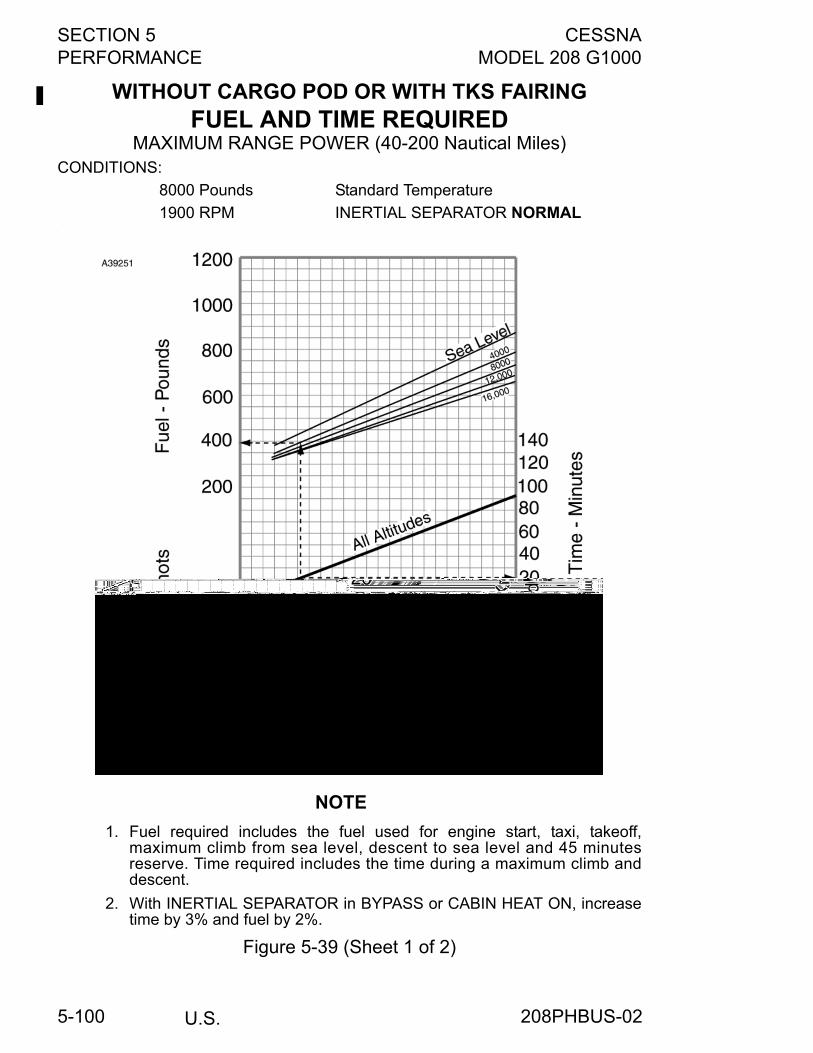
SECTION 5 CESSNAPERFORMANCE MODEL 208 G1000
U.S.5-100
WITHOUT CARGO POD OR WITH TKS FAIRINGFUEL AND TIME REQUIRED
MAXIMUM RANGE POWER (40-200 Nautical Miles)CONDITIONS:
8000 Pounds Standard Temperature
1900 RPM INERTIAL SEPARATOR NORMAL.
NOTE
1. Fuel required includes the fuel used for engine start, taxi, takeoff,maximum climb from sea level, descent to sea level and 45 minutesreserve. Time required includes the time during a maximum climb anddescent.
2. With INERTIAL SEPARATOR in BYPASS or CABIN HEAT ON, increasetime by 3% and fuel by 2%.
Figure 5-39 (Sheet 1 of 2)
208PHBUS-02
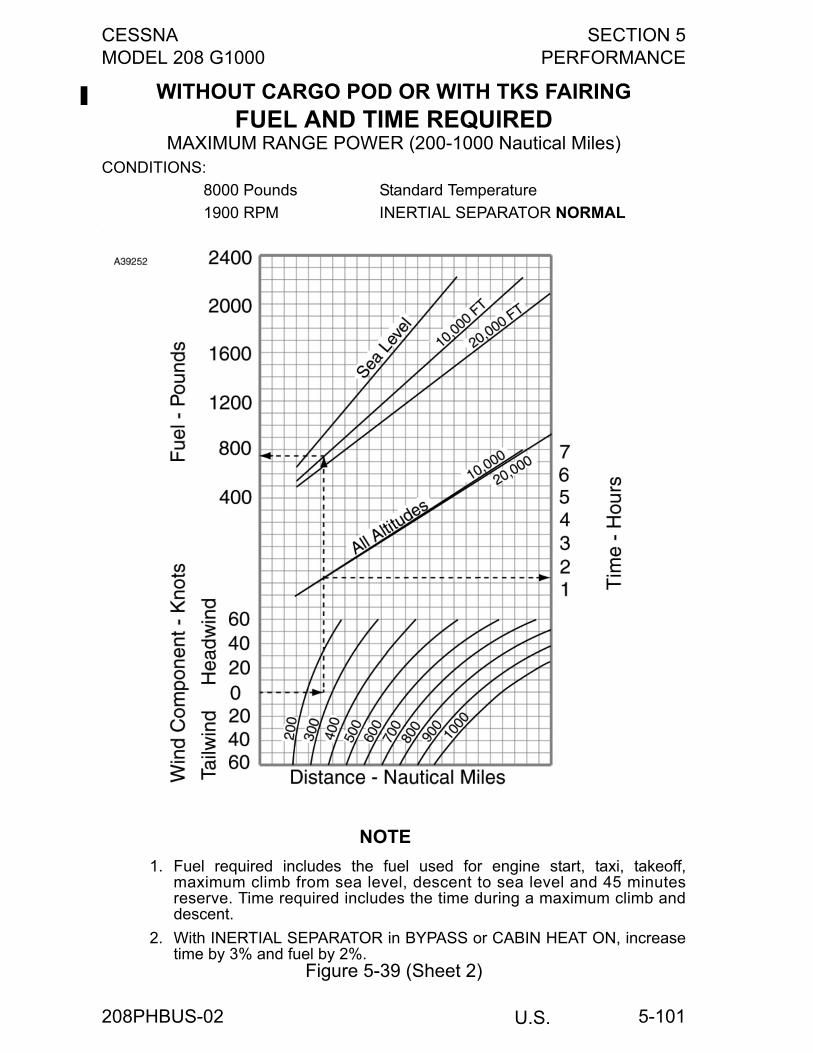
CESSNA SECTION 5MODEL 208 G1000 PERFORMANCE
U.S.
5-101
WITHOUT CARGO POD OR WITH TKS FAIRINGFUEL AND TIME REQUIRED
MAXIMUM RANGE POWER (200-1000 Nautical Miles)CONDITIONS:
8000 Pounds Standard Temperature
1900 RPM INERTIAL SEPARATOR NORMAL.
NOTE
1. Fuel required includes the fuel used for engine start, taxi, takeoff,maximum climb from sea level, descent to sea level and 45 minutesreserve. Time required includes the time during a maximum climb anddescent.
2. With INERTIAL SEPARATOR in BYPASS or CABIN HEAT ON, increasetime by 3% and fuel by 2%.
Figure 5-39 (Sheet 2)
208PHBUS-02
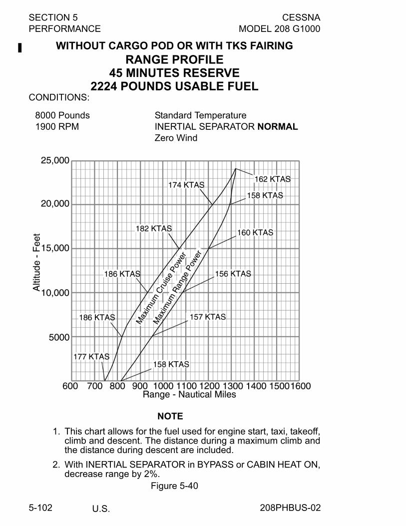
SECTION 5 CESSNAPERFORMANCE MODEL 208 G1000
U.S.5-102
WITHOUT CARGO POD OR WITH TKS FAIRINGRANGE PROFILE
45 MINUTES RESERVE2224 POUNDS USABLE FUEL
CONDITIONS:
NOTE
1. This chart allows for the fuel used for engine start, taxi, takeoff,climb and descent. The distance during a maximum climb andthe distance during descent are included.
2. With INERTIAL SEPARATOR in BYPASS or CABIN HEAT ON,decrease range by 2%.
Figure 5-40
8000 Pounds1900 RPM
Standard TemperatureINERTIAL SEPARATOR NORMALZero Wind
208PHBUS-02
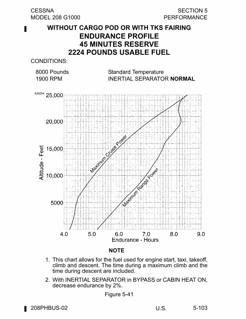
CESSNA SECTION 5MODEL 208 G1000 PERFORMANCE
U.S.
5-103
WITHOUT CARGO POD OR WITH TKS FAIRINGENDURANCE PROFILE45 MINUTES RESERVE
2224 POUNDS USABLE FUELCONDITIONS:
NOTE
1. This chart allows for the fuel used for engine start, taxi, takeoff,climb and descent. The time during a maximum climb and thetime during descent are included.
2. With INERTIAL SEPARATOR in BYPASS or CABIN HEAT ON,decrease endurance by 2%.
Figure 5-41
8000 Pounds1900 RPM
Standard TemperatureINERTIAL SEPARATOR NORMAL
208PHBUS-02
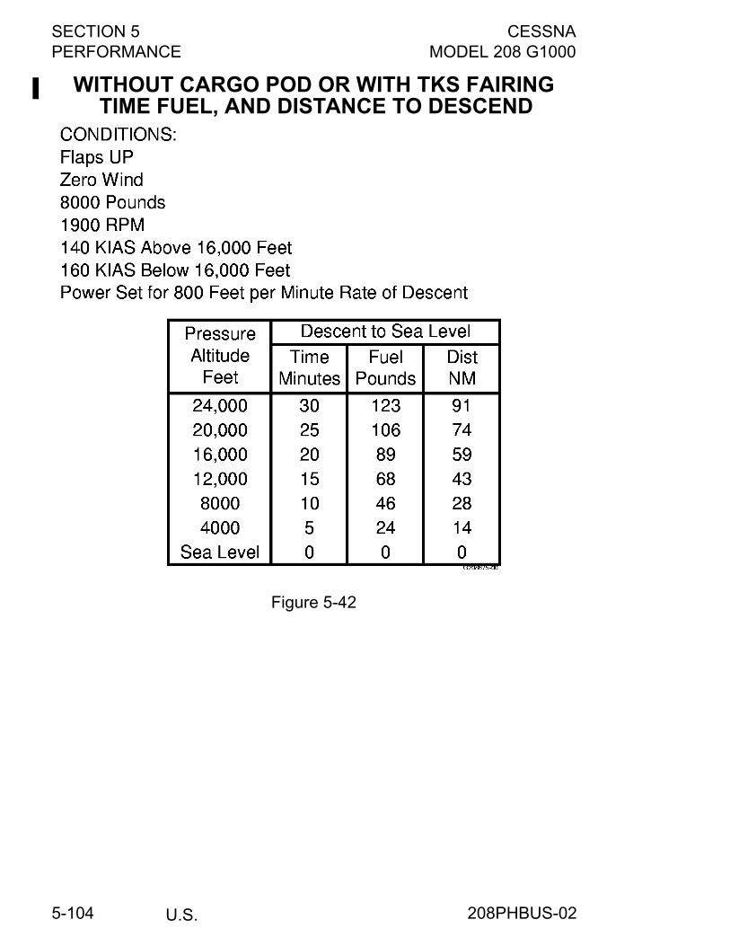
SECTION 5 CESSNAPERFORMANCE MODEL 208 G1000
U.S.5-104
WITHOUT CARGO POD OR WITH TKS FAIRING TIME FUEL, AND DISTANCE TO DESCEND
Figure 5-42
208PHBUS-02
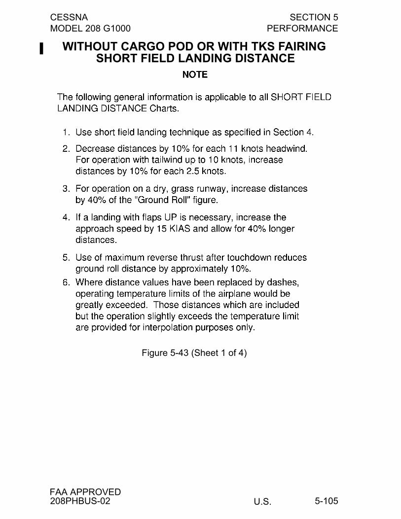
CESSNA SECTION 5MODEL 208 G1000 PERFORMANCE
U.S.FAA APPROVED
5-105
WITHOUT CARGO POD OR WITH TKS FAIRING SHORT FIELD LANDING DISTANCE
Figure 5-43 (Sheet 1 of 4)
208PHBUS-02
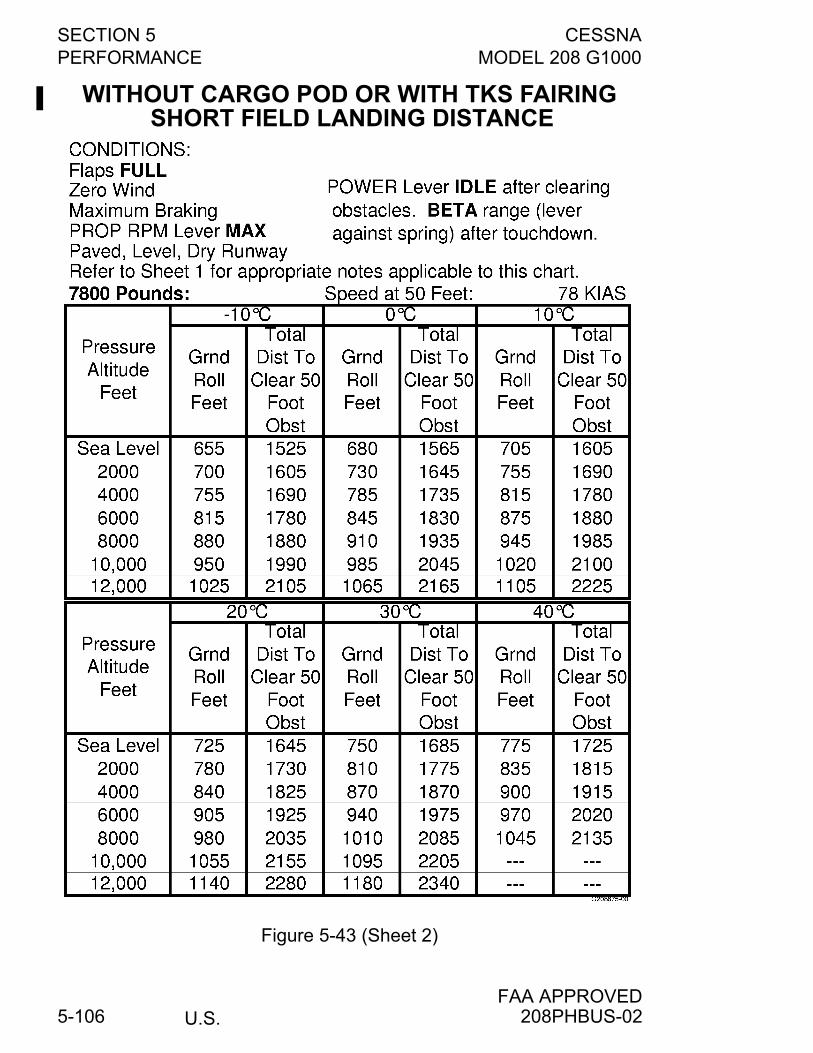
SECTION 5 CESSNAPERFORMANCE MODEL 208 G1000
U.S.FAA APPROVED
5-106
WITHOUT CARGO POD OR WITH TKS FAIRING SHORT FIELD LANDING DISTANCE
Figure 5-43 (Sheet 2)
208PHBUS-02
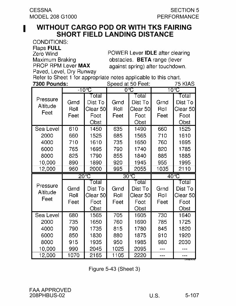
CESSNA SECTION 5MODEL 208 G1000 PERFORMANCE
U.S.FAA APPROVED
5-107
WITHOUT CARGO POD OR WITH TKS FAIRING SHORT FIELD LANDING DISTANCE
Figure 5-43 (Sheet 3)
208PHBUS-02
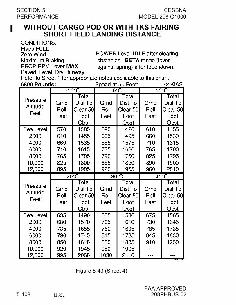
SECTION 5 CESSNAPERFORMANCE MODEL 208 G1000
U.S.FAA APPROVED
5-108
WITHOUT CARGO POD OR WITH TKS FAIRING SHORT FIELD LANDING DISTANCE
Figure 5-43 (Sheet 4)
208PHBUS-02
CESSNA SECTION 6MODEL 208 G1000 WEIGHT AND BALANCE/EQUIPMENT LIST
U.S. 6-1
WEIGHT AND BALANCE/EQUIPMENT LIST
TABLE OF CONTENTSPage
Introduction . . . . . . . . . . . . . . . . . . . . . . . . . . . . . . . . . . . . . . . . . . . .6-3Airplane Weighing Form . . . . . . . . . . . . . . . . . . . . . . . . . . . . . . . . . .6-4Weight and Balance Record . . . . . . . . . . . . . . . . . . . . . . . . . . . . . . .6-5Airplane Weighing Procedures . . . . . . . . . . . . . . . . . . . . . . . . . . . . .6-6Weight and Balance. . . . . . . . . . . . . . . . . . . . . . . . . . . . . . . . . . . . . .6-8
Weight and Balance Plotter. . . . . . . . . . . . . . . . . . . . . . . . . . . . . 6-11Crew and Passenger Loading . . . . . . . . . . . . . . . . . . . . . . . . . . . . . 6-11Baggage/Cargo Loading . . . . . . . . . . . . . . . . . . . . . . . . . . . . . . . . .6-12
Cargo Pod . . . . . . . . . . . . . . . . . . . . . . . . . . . . . . . . . . . . . . . . . .6-17Maximum Zone/Compartment Loadings . . . . . . . . . . . . . . . . . . .6-17Center of Gravity Precautions . . . . . . . . . . . . . . . . . . . . . . . . . . .6-18
Cargo Load Restraint. . . . . . . . . . . . . . . . . . . . . . . . . . . . . . . . . . . .6-19Prevention of Movement . . . . . . . . . . . . . . . . . . . . . . . . . . . . . . .6-19
Transportation of Hazardous Materials . . . . . . . . . . . . . . . . . . . . . .6-21Equipment List . . . . . . . . . . . . . . . . . . . . . . . . . . . . . . . . . . . . . . . . .6-21Cabin Internal Dimensions. . . . . . . . . . . . . . . . . . . . . . . . . . . . . . . .6-22Pod Internal Dimensions and Load Markings . . . . . . . . . . . . . . . . .6-23Cargo Barrier and Barrier Nets . . . . . . . . . . . . . . . . . . . . . . . . . . . .6-24Cargo Partition Nets . . . . . . . . . . . . . . . . . . . . . . . . . . . . . . . . . . . .6-25Cargo Tie-Down Attachments . . . . . . . . . . . . . . . . . . . . . . . . . . . . .6-26Floor Track, Anchor Plate and
Plywood Floor Arrangement . . . . . . . . . . . . . . . . . . . . . . . . . . . .6-28Maximum Cargo Sizes. . . . . . . . . . . . . . . . . . . . . . . . . . . . . . . . . . .6-29Cabin Internal Loading Arrangements . . . . . . . . . . . . . . . . . . . . . . .6-30Cargo Pod Loading Arrangements . . . . . . . . . . . . . . . . . . . . . . . . .6-33Loading-Tie-Down by Zone and Load . . . . . . . . . . . . . . . . . . . . . . .6-34Typical Cargo Restraint Methods. . . . . . . . . . . . . . . . . . . . . . . . . . .6-35Weight and Moment Tables . . . . . . . . . . . . . . . . . . . . . . . . . . . . . . .6-36Sample Loading Problem . . . . . . . . . . . . . . . . . . . . . . . . . . . . . . . .6-44Center of Gravity Limits . . . . . . . . . . . . . . . . . . . . . . . . . . . . . . . . . .6-46Center of Gravity Moment Envelope . . . . . . . . . . . . . . . . . . . . . . . .6-47
208PHBUS-02

SECTION 6 CESSNAWEIGHT AND BALANCE/EQUIPMENT LIST MODEL 208 G1000
U.S.6-2
This Page Intentionally Left Blank
208PHBUS-02
CESSNA SECTION 6MODEL 208 G1000 WEIGHT AND BALANCE/EQUIPMENT LIST
U.S. 6-3
INTRODUCTIONThis section describes the procedure for establishing the basic emptyweight and moment of the airplane. Sample forms are provided forreference. Procedures for calculating the weight and moment forvarious operations are also provided.In order to achieve the performance and flight characteristics which aredesigned into the airplane, it must be flown within approved weight andcenter of gravity limits. Although the airplane offers flexibility of loading,it cannot be flown with full fuel tanks and a full complement ofpassengers or a normal crew and both cabin and cargo pod (ifinstalled) loading zones filled to maximum capacity. The pilot mustutilize the loading flexibility to ensure the airplane does not exceed itsmaximum weight limits and is loaded within the center of gravity rangebefore takeoff.Weight is important because it is a basis for many flight and structuralcharacteristics. As weight increases, takeoff speed must be greatersince stall speeds are increased, the rate of acceleration decreases,and the required takeoff distance increases. Weight in excess of themaximum takeoff weight may be a contributing factor to an accident,especially when coupled with other factors such as temperature, fieldelevation, and runway conditions, all of which may adversely affect theairplane's performance. Climb, cruise, and landing performance willalso be affected. Flights at excess weight are possible, and may bewithin the performance capability of the airplane, but loads for whichthe airplane was not designed may be imposed on the structure,especially during landing.The pilot should routinely determine the balance of the airplane since itis possible to be within the maximum weight limit and still exceed thecenter of gravity limits. An airplane loading which exceeds the forwardcenter of gravity limit may place heavy loads on the nose wheel, andthe airplane will be slightly more difficult to rotate for takeoff or flare forlanding. If the center of gravity is too far aft, the airplane may rotateprematurely on takeoff, depending on trim settings.
(Continued Next Page)
208PHBUS-00
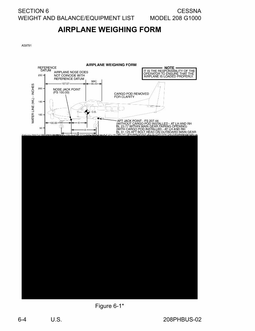
SECTION 6 CESSNAWEIGHT AND BALANCE/EQUIPMENT LIST MODEL 208 G1000
U.S.6-4
AIRPLANE WEIGHING FORM
Figure 6-1*
208PHBUS-02
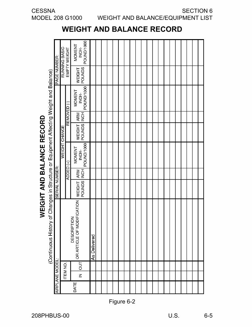
CESSNA SECTION 6MODEL 208 G1000 WEIGHT AND BALANCE/EQUIPMENT LIST
U.S. 6-5
WEIGHT AND BALANCE RECORD
Figure 6-2
208PHBUS-00
SECTION 6 CESSNAWEIGHT AND BALANCE/EQUIPMENT LIST MODEL 208 G1000
U.S.6-6
INTRODUCTION (Continued)
A properly loaded airplane; however, will perform as intended. Beforethe airplane is licensed, a basic empty weight, center of gravity (C.G.)and moment are computed. Specific information regarding the weight,arm, moment, and installed equipment for this airplane as deliveredfrom the factory can be found in the plastic envelope in the back of thisPOH/AFM. Using the basic empty weight and moment, the pilot candetermine the weight and moment for the loaded airplane by computingthe total weight and moment and then determining whether they arewithin the approved Center of Gravity Moment Envelope.
WARNING
It is the responsibility of the pilot to make sure thatthe airplane is loaded properly. Operation outsideof prescribed weight and balance limitations couldresult in an accident and serious or fatal injury.
AIRPLANE WEIGHING PROCEDURES1. Preparation:
a. Remove all snow, ice or water which may be on theairplane.
b. Inflate tires to recommended operating pressure.c. Lock open fuel tank sump quick-drains and fuel reservoir
quick-drain to drain all fuel.d. For aircraft with non-standard (optional) equipment installed,
see the appropriate POH/AFM supplement for additionalweighing procedures.
e. Service engine oil as required to obtain a normal fullindication (MAX HOT or MAX COLD, as appropriate, ondipstick).
f. Slide to move pilot and front passenger seats to position theseat locking pins on the back legs of each seat at FuselageStation 145.0. Aft passenger seats (if installed) haverecommended fixed positions and should be located, usinga Fuselage Station location code on the seat rails, asdescribed in the Cabin Internal Loading Arrangementsfigure. In the event the aft seats were moved toaccommodate a custom loading, they should be returned tothe standard locations prior to weighing.
g. Raise flaps to fully retracted positions.h. Place all control surfaces in neutral position.
(Continued Next Page)
208PHBUS-01
CESSNA SECTION 6MODEL 208 G1000 WEIGHT AND BALANCE/EQUIPMENT LIST
U.S. 6-7
AIRPLANE WEIGHING PROCEDURES (Continued)2. Leveling:
a. Place scales under each wheel (minimum scale capacity,2000 pounds nose, 4000 pounds each main). The mainlanding gear must be supported by stands, blocks, etc., onthe main gear scales to a position at least four inches higherthan the nose gear as it rests on an appropriate scale. Thisinitial elevated position will compensate for the difference inwaterline station between the main and nose gear so thatfinal leveling can be accomplished solely by deflating thenose gear tire.
b. Deflate the nose tire to properly center the bubble in thelevel (see Airplane Weighing Form). Since the nose gearstrut contains an oil snubber for shock absorption ratherthan an air/oil strut, it can not be deflated to aid in airplaneleveling.
3. Weighing:a. Weigh airplane in a closed hangar to avoid errors caused by
air currents.b. With the airplane level and brakes released, record the
weight shown on each scale. Deduct the tare from eachreading.
4. Measuring:a. Obtain measurement A by measuring horizontally (along
airplane centerline) from a line stretched between the mainwheel centers to a plumb bob dropped from the center of thenose jack point located below the firewall and housed withinthe nose strut fairing.
b. Obtain measurement B by measuring horizontally andparallel to the airplane centerline, from center of nose wheelaxle, left side, to a plumb bob dropped from the line betweenthe main wheel centers. Repeat on right side and calculatethe average of the measurements.
5. Using weights from step 3 and measurements from step 4, theairplane weight and C.G. can be determined.
6. Basic Empty Weight may be determined by completing theAirplane Weighing Form in this section.
208PHBUS-00
SECTION 6 CESSNAWEIGHT AND BALANCE/EQUIPMENT LIST MODEL 208 G1000
U.S.6-8
WEIGHT AND BALANCEThe following information will enable you to operate your Cessna withinthe prescribed weight and center of gravity limitations. To figure weightand balance, use the Sample Loading Problem, Weight and MomentTables, and Center of Gravity Moment Envelope as follows:
1. Take the basic empty weight and moment from appropriateweight and balance records carried in your airplane, and enterthem in the column titled, “YOUR AIRPLANE” on the SampleLoading Problem.
NOTE
In addition to the basic empty weight and moment noted onthese records, the C.G. arm (Fuselage Station) is alsoshown, but need not be used on the Sample LoadingProblem. The moment which is shown must be divided by1000 and this value used as the moment/1000 on theloading problem.
2. Use the Weight and Moment Tables to determine the moment/1000 for each additional item to be carried; then list these on theloading problem.
NOTE
Information on the Weight and Moment Tables for differentfuel grades is based on average fuel density at fueltemperatures of 60°F. However, fuel weight increasesapproximately 0.1 pounds per gallon for each 25°Fdecrease in fuel temperature. Therefore, whenenvironmental conditions are such that the fuel temperatureis different than shown in the chart heading, a new fuelweight calculation should be made using the 0.1 poundsper gallon increase in fuel weight for each 25°F decrease infuel temperature. Assume the tanks are completely filledand the fuel temperature is at 35°F (25°F below the 60°Fnoted on the chart).
(Continued Next Page)
208PHBUS-02
CESSNA SECTION 6MODEL 208 G1000 WEIGHT AND BALANCE/EQUIPMENT LIST
U.S. 6-9
WEIGHT AND BALANCE (Continued)3. Calculate the revised fuel weight by multiplying the total usable
fuel by the sum of the average density (stated on chart) plus theincrease in density estimated for the lower fuel temperature. Inthis particular sample, as shown by the calculation below, theresulting fuel weight increase due to lower fuel temperature willbe 33.6 pounds over the 2224 pounds (for 332 gallons) shownon the chart, which might be significant in an actual loadingsituation:
332 gallons X (6.7 + 0.1 pounds per gallon) = 2257.6 poundsrevised fuel weight.
Then calculate the revised fuel moment. The revised moment isin direct proportion to the revised fuel weight:
The revised moment of X = 413.4. This value would be used on theSample Loading Problem as the moment/1000 in conditionsrepresented by this sample.
(Continued Next Page)
X (revised moment)407.2 (average moment)
= 2257.6 (revised weight)= 2224 (average weight)
X = (407.2 X 2257.6) / 2224
208PHBUS-02
SECTION 6 CESSNAWEIGHT AND BALANCE/EQUIPMENT LIST MODEL 208 G1000
U.S.6-10
WEIGHT AND BALANCE (Continued)
NOTE
Information on the Weight and Moment Tables for crew,passenger, and cargo is based on the pilot and frontpassenger sliding seats positioned for average occupants(e.g., Fuselage Station 135.5), the aft passenger fixed seats(if installed) in the recommended position, and the baggageor cargo uniformly loaded around the center (e.g., FuselageStation 168.4 in Zone 1) of the zone fore and aft boundaries(e.g., Fuselage Stations 155.4 and 181.5 in Zone 1) shownon the Cabin Internal Loading Arrangements figure. Forloadings which may differ from these, the LoadingArrangements figure and Sample Loading Problem listsFuselage Stations for these items to indicate their forwardand aft C.G. range limitations. Additional momentcalculations, based on the actual weight and C.G. arm(Fuselage Station) of the item being loaded, must be madeif the position of the load is different from that shown on theWeight and Moment Tables. For example, if seats are inany position other than stated on the Cabin InternalLoading Arrangements figure, the moment must becalculated by multiplying the occupant weight times the armin inches. A point nine inches forward of the intersection ofthe seat bottom and seat back (with cushions compressed)can be assumed to be the occupant C.G. For a reference indetermining the arm, the forward face of the raised aftcargo floor is Fuselage Station 284.0.
Total the weights and moments/1000 and plot these values on theCenter of Gravity Moment Envelope to determine whether the pointfalls within the envelope, and if the loading is acceptable.
WARNING
It is the responsibility of the pilot to make sure thatthe airplane is correctly loaded. Operation outsideof prescribed weight and balance limitations couldresult in an accident and serious or fatal injury.
208PHBUS-02
CESSNA SECTION 6MODEL 208 G1000 WEIGHT AND BALANCE/EQUIPMENT LIST
U.S. 6-11
WEIGHT AND BALANCE PLOTTERA Weight and Balance Plotter is available to quickly determine theweight and balance of the airplane when loading. If the plotter shows amarginal condition developing, or if there is a question concerning theresults in any way, then a more precise weight and balance should bedetermined using the weight and balance procedure in this section.Instructions for use of the plotter are included on the plotter.
CREW AND PASSENGER LOADINGThe pilot and front passenger positions have six-way adjustable seats.These seats slide fore and aft on tracks that have adjustment holes forseat position. The Standard 208 has aft passenger seating with three configurationsof Commuter Seating. The first Commuter Seating configuration has two individual,fixed-position passenger seats on the left side of the cabin, and threetwo-place fixed-position, bench seats located on the right side of thecabin in a staggered arrangement.The second Commuter Seating configuration includes four individual,fixed-position, passenger seats on the left side of the cabin and fourindividual, fixed-position passenger seats on the right side of the cabinin a side-by-side arrangement.The third Commuter Seating configuration has three individual, fixedposition passenger seats on the left side of the cabin, and threetwo-place fixed-position, bench seats located on the right side of thecabin in a side-by-side arrangement.
WARNING
None of the airplane seats are approved forinstallation facing aft.
208PHBUS-02
SECTION 6 CESSNAWEIGHT AND BALANCE/EQUIPMENT LIST MODEL 208 G1000
U.S.6-12
BAGGAGE/CARGO LOADING
CABIN CARGO AREATo facilitate the carrying of large or bulky items, all aft seats and thefront passenger seat may be removed from the airplane. If a cargobarrier and its three barrier nets are available for installation, removal ofthe front passenger seat may not be desired. Mission requirements willdictate whether the barrier is to be used and the number of seatsremoved. If seats are removed for hauling cargo and the cargo barrierand its nets added, the basic empty weight and C.G. moment of theairplane should be adjusted so that these values accurately representthe weight and moment of the airplane before loading. To calculate thenew weight and moment, refer to the airplane equipment list andacquire the weight and C.G. arm of each item of equipment to beremoved or added, then record these values on Figure 6-2, SampleWeight and Balance Record, to assist in the calculation. For each itemof equipment, multiply its weight by its C.G. arm to provide the momentfor that item. Subtract weights of removed items (seats) and addweights of installed items (cargo barrier and its nets) to the originalbasic empty weight to provide a new basic empty weight. Likewise,subtract the moments of removed items and add the moments ofinstalled items to the original moment to provide a new airplanemoment. (Remember that the moment value is to be divided by 1000 toreduce the number of digits.) The new basic empty weight andmoment/1000 can be used as illustrated in the Sample LoadingProblem when figuring airplane loading with the selected items ofequipment removed/installed. With all the seats except the pilot's seat removed, a large cabin volume(341.4 cubic feet, less the volume required for the pilot) is available forbaggage/cargo. If a cargo barrier is installed, the total volume availablefor cargo behind the barrier is 254 cubic feet. Cargo can be loadedthrough the large, almost square, two-piece cargo door. The floor is flatfrom the firewall at Fuselage Station 100.0, except in the rudder pedalarea, to the aft side of the cargo door (Fuselage Station 284.0), and hasa 200 pound per square foot allowable loading. Strategically locatednutplates are provided which will allow the installation of plywoodflooring for ease of loading and distribution of concentrated loads.Between Fuselage Station 284.0 and 308.0, additional baggage/cargospace is provided on a raised floorboard approximately five inchesabove the main floorboard.
(Continued Next Page)
208PHBUS-00
CESSNA SECTION 6MODEL 208 G1000 WEIGHT AND BALANCE/EQUIPMENT LIST
U.S. 6-13
CABIN CARGO AREA (Continued)
In the area of the removed front passenger seat, I section seat tracksare installed from Fuselage Station 125.0 to 159.98, and tie-down blockassemblies (available from any Cessna Dealer) which clamp to thetracks can be installed to serve as tie-down attach points. FromFuselage Station 158 aft to the raised baggage/cargo floor, the seattracks are designed to receive quick-release tie-down fittings which canbe snapped into the tracks at intervals of one inch. The raisedbaggage/cargo floor contains eight anchor plates to which quick-release tie-down fittings can be attached. If rope, cable or other fittingsare used for tie-downs, they should be rated at a minimum of 2100pounds when used with all fittings noted in the table on the Cargo Tie-Down Attachments figure, except the double-stud quick-release tie-downs which require a 3150 pound rating. Maximum allowable cargoloads will be determined by the individual zone weight limitations andby the airplane weight and C.G. limitations. The number of tie-downsrequired is dependent on the load(s) to be secured. The Cargo Tie-Down Attachments figure shows the maximum allowable cargo weightfor each type of cargo tie-down attachment.
CAUTION
The maximum load values listed in each zone arepredicated on all cargo being tied down within thezones.
Each zone should be loaded to at least 75% full by volume prior toloading the next zone. In addition, if the load in Zone 5 exceeds 400pounds, a cargo partition net (if available) is required aft of the load orthe load must be secured to the floor.
(Continued Next Page)
208PHBUS-00
SECTION 6 CESSNAWEIGHT AND BALANCE/EQUIPMENT LIST MODEL 208 G1000
U.S.6-14
CABIN CARGO AREA (Continued)
A cargo barrier and three barrier nets are available for installationdirectly behind the pilot's and front passenger's seats. The barrier andnets preclude loose cargo from moving forward into the pilot's and frontpassenger's stations during an abrupt deceleration. The barrierconsists of a U-shaped assembly of honeycomb compositeconstruction. The assembly attaches to the four pilot and frontpassenger seat rails at the bottom at Fuselage Station 153.0 and to thewing carry-thru spar at the top at approximately Fuselage Station 166.0.The cargo barrier nets consist of three nets: one for the left sidewall,one for the right sidewall, and one for the center. The left and right netsfill in the space between the barrier assembly and the airplanesidewalls. The side nets are fastened to the airplane sidewalls and theedge of the barrier with six quick-release fasteners each, three on eachside. The center net fills in the opening in the top center of the barrier.The center net is fastened with four fasteners, two on each side.Horizontal lines, labeled 75, are marked on the aft side of the cargobarrier. Placards above the horizontal lines caution that the maximumallowable load behind the barrier is 2900 pounds total, and that zonesforward of the last loaded zone must be at least 75% full by volume.Refer to the Cargo Barrier and Barrier Nets figure for additional details.
WARNING
• When utilized, the cargo barrier and its attachednets provide cargo forward crash load restraintand protection of the pilot and front passenger;however, the cargo must still be secured toprevent it from shifting due to takeoff, flight,landing, and taxi accelerations anddecelerations. On the Standard 208, ifpassengers as well as cargo, are located aft ofthe barrier, cargo placement must allowmovement and exit of the passengers and thecargo must be secured for crash load restraintconditions. Refer to Cargo Load Restraint in thissection for additional information concerningcargo restraint with and without a cargo barrier.
• Make sure the barrier net fasteners are securedfor takeoff, landing, and inflight operations, andare momentarily detached only for movement ofthe nets for loading/unloading of items throughthe crew area.
(Continued Next Page)
208PHBUS-00
CESSNA SECTION 6MODEL 208 G1000 WEIGHT AND BALANCE/EQUIPMENT LIST
U.S. 6-15
CABIN CARGO AREA (Continued)
Cargo partition nets are available and can be installed to divide thecargo area into convenient compartments. Partitions may be installed inall of the five locations at Fuselage Station 181.5, 208.0, 234.0, 259.0,and 284.0. The cargo partitions are constructed of canvas with nylonwebbing reinforcement straps crisscrossing the partition for addedstrength. The ends of the straps have quick-release fasteners whichattach to the floor tracks and two floor-mounted anchor plates locatedjust forward of the raised cargo floor and other anchor plates on thesidewalls and ceiling. Four straps have adjustable buckles fortightening the straps during installation of the partition. Refer to theCargo Partition Nets figure for additional details.Zones divided by cargo partitions can be loaded without additional tie-downs if a total loaded density for each partitioned zone does notexceed 9.75 pounds per cubic foot and the zone is more than 75% full.Cargo loading that does not meet these requirements must be securedto the cabin floor.
CAUTION
The maximum cargo partition load is the sum of anytwo zones. No more than two adjacent zones can bedivided by one partition. The partitions are designed toprevent the cargo from shifting forward and aft in flight.They should not be considered adequate to withstandcrash loads and do not replace the need for a cargobarrier.
(Continued Next Page)
208PHBUS-02
SECTION 6 CESSNAWEIGHT AND BALANCE/EQUIPMENT LIST MODEL 208 G1000
U.S.6-16
CABIN CARGO AREA (Continued)
Various tie-down belt assemblies and tie-down ring anchors areavailable for securing cargo within the airplane. The belts may also beused for tying down the airplane. A standard configuration is offeredand contains three 3000-pound rated belt assemblies with ratchet-typeadjusters and six single-stud, quick-release tie-down ring anchors. Aheavy-duty configuration consists of three 5000-pound rated belts withratchet-type adjusters and six double-stud, quick-release anchors.Three 5000-pound rated belts with overcenter-type locking devices arealso available for heavy-duty use. The six single-stud and double-studtie-down ring anchors are also available separately. The single-studanchors can be attached to any tie-down point in the airplane whichisn’t placarded for attachment for partition nets only, whereas thedouble-stud anchors can be attached to the aft seat tracks only. Seethe Cargo Tie-Down Attachments figure for maximum load ratings andtie-down ring anchor spacing restrictions.Refer to Maximum Zone/Compartment Loading for maximum zoneweight limits.
CAUTION
The maximum zone weight limits in each zone arepredicated on all cargo being tied down within thezones.
208PHBUS-02
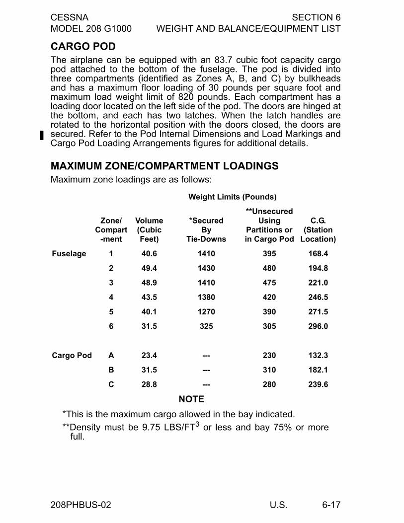
CESSNA SECTION 6MODEL 208 G1000 WEIGHT AND BALANCE/EQUIPMENT LIST
U.S. 6-17
CARGO PODThe airplane can be equipped with an 83.7 cubic foot capacity cargopod attached to the bottom of the fuselage. The pod is divided intothree compartments (identified as Zones A, B, and C) by bulkheadsand has a maximum floor loading of 30 pounds per square foot andmaximum load weight limit of 820 pounds. Each compartment has aloading door located on the left side of the pod. The doors are hinged atthe bottom, and each has two latches. When the latch handles arerotated to the horizontal position with the doors closed, the doors aresecured. Refer to the Pod Internal Dimensions and Load Markings andCargo Pod Loading Arrangements figures for additional details.
MAXIMUM ZONE/COMPARTMENT LOADINGSMaximum zone loadings are as follows:
NOTE
*This is the maximum cargo allowed in the bay indicated.
**Density must be 9.75 LBS/FT3 or less and bay 75% or morefull.
Weight Limits (Pounds)
Zone/Compart
-ment
Volume (Cubic Feet)
*SecuredBy
Tie-Downs
**Unsecured Using
Partitions or in Cargo Pod
C.G.(Station
Location)
Fuselage 1 40.6 1410 395 168.4
2 49.4 1430 480 194.8
3 48.9 1410 475 221.0
4 43.5 1380 420 246.5
5 40.1 1270 390 271.5
6 31.5 325 305 296.0
Cargo Pod A 23.4 --- 230 132.3
B 31.5 --- 310 182.1
C 28.8 --- 280 239.6
208PHBUS-02
SECTION 6 CESSNAWEIGHT AND BALANCE/EQUIPMENT LIST MODEL 208 G1000
U.S.6-18
CENTER OF GRAVITY PRECAUTIONSSince the airplane can be used for cargo missions, carrying varioustypes of cargo in a variety of loading configurations, precautions mustbe taken to protect the forward and aft C.G. limits. Load planning shouldinclude a careful comparison of the mission requirements with thevolume and weight limitation in each loading zone and the final airplaneC.G. Cargo loaded in the forward zones may need to be balanced byloading cargo in one or more aft zones. Conversely, loadings can notbe concentrated in the rear of the airplane, but must be compensatedby forward cargo to maintain balance. Under ideal conditions, loadingsshould be accomplished with heavy items on the bottom and the loaddistributed uniformly around the C.G. of the cabin cargo area zone and/or cargo pod compartment. Loading personnel must maintain strictaccountability for loading correctly and accurately, but may not alwaysbe able to achieve an ideal loading. A means of protecting the C.G. aftlimit is provided by supplying an aft C.G. location warning area between38.33% MAC and the maximum allowable aft C.G. of 40.33% MAC.The warning area is indicated by shading on the C.G. MomentEnvelope and C.G. Limits figures.
CAUTION
• This shaded area should be used only if accurateC.G. determination can be obtained.
• Exercise caution while loading or unloading heavycargo through the cargo doors. An ideal loading inevery other respect can still cause tail tipping andstructural damage if proper weight distribution isignored. For example, heavy cargo loaded troughthe doors and placed momentarily in zones 4 and 5,plus the weight of personnel required to move it to aforward zone, could cause an out-of-balancecondition during loading.
208PHBUS-02
CESSNA SECTION 6MODEL 208 G1000 WEIGHT AND BALANCE/EQUIPMENT LIST
U.S. 6-19
CARGO LOAD RESTRAINT
PREVENTION OF MOVEMENTCargo restraint requires the prevention of movement in five principaldirections: forward, aft, upward (vertical), left (side), and right (side).These movements are the result of forces exerted upon the cargo dueto acceleration or deceleration of the airplane in takeoffs and landingsas well as forces due to air turbulence in flight. Correct restraintprovides the proper relationship between airplane configuration (with orwithout barrier), weight of the cargo, and the restraint required.Restraint is required for flight, landing, taxi loads, and for crash loads.Cargo must be tied down for flight, landing, and taxi load, and/or crashload. When a cargo barrier is not installed, all cargo must be preventedfrom movement in the five principal directions and secured to providecrash load restraint. The maximum rated loads specified for loadingswithout a barrier in the table in the Cargo Tie-Down Attachments figureshould be used for each tie-down. Consistent use of these loadingcriteria is important, and it is the responsibility of the pilot to make surethe cargo is restrained properly. When a cargo barrier is installed, cargoaft of the barrier must also be secured to prevent movement in the fiveprincipal directions, but only to the extent that shifting due to flight,landing, and taxi loads is provided. The maximum rated loads specifiedfor loadings with a barrier installed shown in the table in the Cargo Tie-Down Attachments figure should be used for each tie-down. With abarrier installed, all cargo must be loaded such that loading zonesforward of the last loaded zone must be 75% full by volume.
(Continued Next Page)
208PHBUS-00
SECTION 6 CESSNAWEIGHT AND BALANCE/EQUIPMENT LIST MODEL 208 G1000
U.S.6-20
PREVENTION OF MOVEMENT (Continued)
WARNING
In special loading arrangements which allow thecarriage of passengers as well as cargo behind thebarrier in the Standard 208, all cargo must besecured to prevent movement in the five principaldirections and provide the same crash loadrestraint as though a barrier was not installed usingthe maximum rated loads specified for loadingwithout a barrier. In this arrangement, cargoplacement must allow for movement and exit of thepassengers. The pilot must be responsible to makesure proper load restraint in all loadings.
Refer to the Typical Cargo Restraint Methods figure for diagrams oftypical cargo tie-down methods for prevention of movement. Also, thecargo partition nets available for the airplane can be installed atFuselage Stations 181.5, 208.0, 234.0, 259.0 and 284.0 to divide thecabin cargo area into compartments. If the partitions are used, theymust be used in conjunction with the cargo barrier. Since partitions arenot designed to withstand crash loads, they cannot be considered as areplacement for the barrier. Each partition will withstand the forwardand aft operational loads applied during takeoff, flight, and landing byany two zones forward or aft of the partition. Use of the partitions willallow loading of the zones without tying down the cargo if the loaddensity is not more than 9.75 pounds per cubic foot and the zone ismore than 75% full. Cargo loading that does not meet theserequirements must be secured to the cabin floor.
LOADING OF PIERCING OR PENETRATING ITEMSRegardless of cargo location, items of a piercing or penetrating natureshall be located so that other cargo is loaded between the barrier/nets,cargo partitions, and rear wall and the piercing or penetrating items toprovide a buffer. The density of this cargo shall be sufficient to restrainthe piercing or penetrating items from passing through the barrier/nets,partitions, and rear wall under critical emergency landing conditions. Ifthe condition cannot be complied with, the piercing or penetrating itemsshall be tied down separately.
208PHBUS-02
CESSNA SECTION 6MODEL 208 G1000 WEIGHT AND BALANCE/EQUIPMENT LIST
U.S. 6-21
TRANSPORTATION OF HAZARDOUS MATERIALSSpecial protection of the airplane and training of personnel are keyconsiderations in conducting approved transportation of hazardousmaterials.Protection against the damaging effects of leakage of hazardousmaterials has not been provided in the cabin cargo area or cargo pod.Therefore provisions should be made to ensure this protection ifcarriage of these materials is planned.In addition to the pilot-in-command and flight crew member (if used),other personnel such as cargo receiving and loading personnel shouldbe properly trained concerning the acceptance, handling, storage,loading and unloading of hazardous materials if these materials are tobe carried. Information and regulations pertaining to the airtransportation of hazardous materials is outlined in the Code of FederalRegulations (CFR) Title 49 and in the International Civil AviationOrganization (ICAO) Technical Instructions for the Safe Transport ofDangerous Goods by Air.
EQUIPMENT LISTFor a complete list of equipment installed in the airplane as deliveredfrom the manufacturer, refer to the equipment list furnished with theairplane.
208PHBUS-02
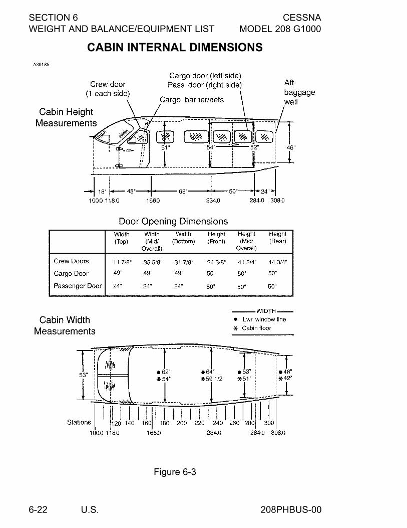
SECTION 6 CESSNAWEIGHT AND BALANCE/EQUIPMENT LIST MODEL 208 G1000
U.S.6-22
CABIN INTERNAL DIMENSIONS
Figure 6-3
208PHBUS-00
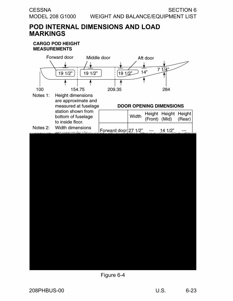
CESSNA SECTION 6MODEL 208 G1000 WEIGHT AND BALANCE/EQUIPMENT LIST
U.S. 6-23
POD INTERNAL DIMENSIONS AND LOAD MARKINGS
Figure 6-4
208PHBUS-00
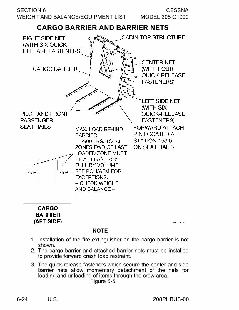
SECTION 6 CESSNAWEIGHT AND BALANCE/EQUIPMENT LIST MODEL 208 G1000
U.S.6-24
CARGO BARRIER AND BARRIER NETS
NOTE
1. Installation of the fire extinguisher on the cargo barrier is notshown.
2. The cargo barrier and attached barrier nets must be installedto provide forward crash load restraint.
3. The quick-release fasteners which secure the center and sidebarrier nets allow momentary detachment of the nets forloading and unloading of items through the crew area.
Figure 6-5
208PHBUS-00
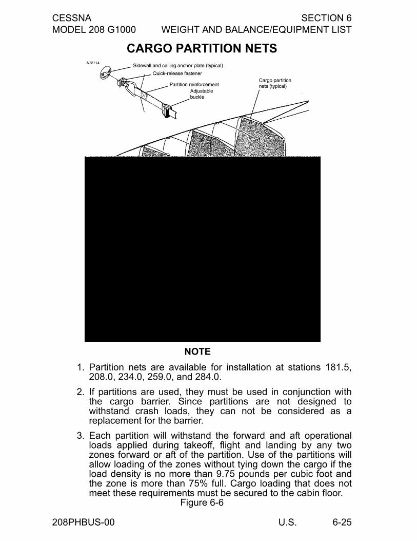
CESSNA SECTION 6MODEL 208 G1000 WEIGHT AND BALANCE/EQUIPMENT LIST
U.S. 6-25
CARGO PARTITION NETS
NOTE
1. Partition nets are available for installation at stations 181.5,208.0, 234.0, 259.0, and 284.0.
2. If partitions are used, they must be used in conjunction withthe cargo barrier. Since partitions are not designed towithstand crash loads, they can not be considered as areplacement for the barrier.
3. Each partition will withstand the forward and aft operationalloads applied during takeoff, flight and landing by any twozones forward or aft of the partition. Use of the partitions willallow loading of the zones without tying down the cargo if theload density is no more than 9.75 pounds per cubic foot andthe zone is more than 75% full. Cargo loading that does notmeet these requirements must be secured to the cabin floor.
Figure 6-6
208PHBUS-00
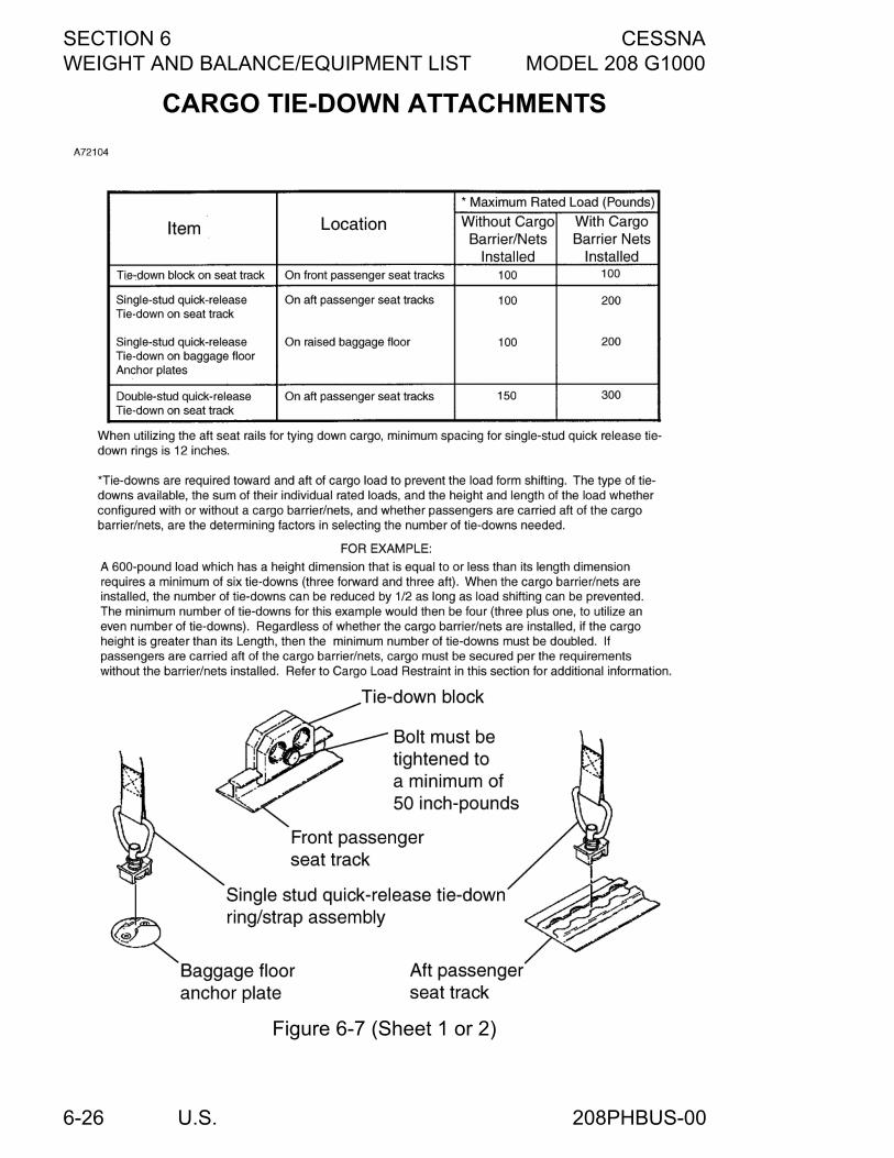
SECTION 6 CESSNAWEIGHT AND BALANCE/EQUIPMENT LIST MODEL 208 G1000
U.S.6-26
CARGO TIE-DOWN ATTACHMENTS
Figure 6-7 (Sheet 1 or 2)
208PHBUS-00
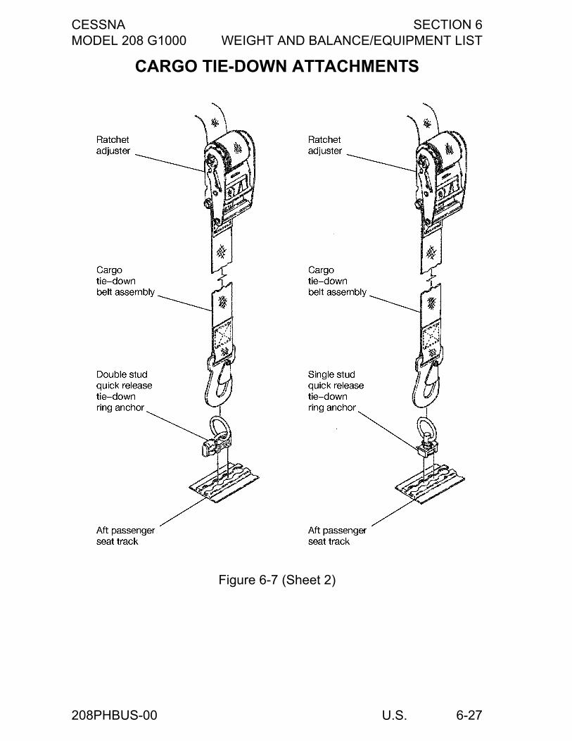
CESSNA SECTION 6MODEL 208 G1000 WEIGHT AND BALANCE/EQUIPMENT LIST
U.S. 6-27
CARGO TIE-DOWN ATTACHMENTS
Figure 6-7 (Sheet 2)
208PHBUS-00
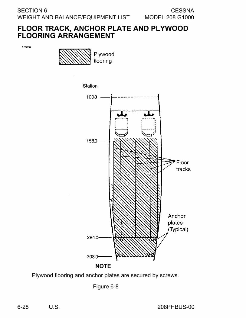
SECTION 6 CESSNAWEIGHT AND BALANCE/EQUIPMENT LIST MODEL 208 G1000
U.S.6-28
FLOOR TRACK, ANCHOR PLATE AND PLYWOOD FLOORING ARRANGEMENT
NOTE
Plywood flooring and anchor plates are secured by screws.
Figure 6-8
208PHBUS-00
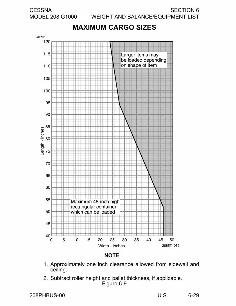
CESSNA SECTION 6MODEL 208 G1000 WEIGHT AND BALANCE/EQUIPMENT LIST
U.S. 6-29
MAXIMUM CARGO SIZES
NOTE
1. Approximately one inch clearance allowed from sidewall andceiling.
2. Subtract roller height and pallet thickness, if applicable.Figure 6-9
208PHBUS-00
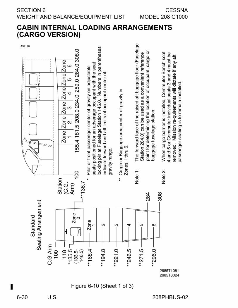
SECTION 6 CESSNAWEIGHT AND BALANCE/EQUIPMENT LIST MODEL 208 G1000
U.S.6-30
CABIN INTERNAL LOADING ARRANGEMENTS (CARGO VERSION)
Figure 6-10 (Sheet 1 of 3)
208PHBUS-02

CESSNA SECTION 6MODEL 208 G1000 WEIGHT AND BALANCE/EQUIPMENT LIST
U.S. 6-31
CABIN INTERNAL LOADING ARRANGEMENTS (PASSENGER VERSION)
(Continued Next Page)Figure 6-10 (Sheet 2)*
208PHBUS-02
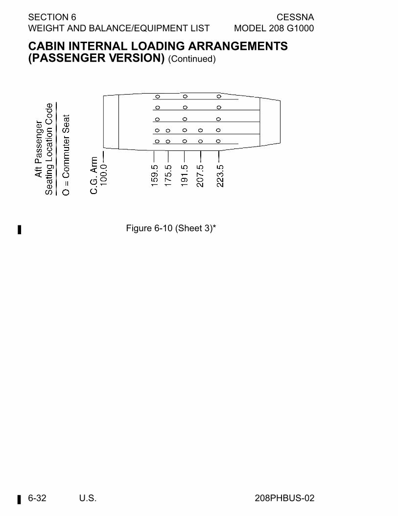
SECTION 6 CESSNAWEIGHT AND BALANCE/EQUIPMENT LIST MODEL 208 G1000
U.S.6-32
CABIN INTERNAL LOADING ARRANGEMENTS (PASSENGER VERSION) (Continued)
Figure 6-10 (Sheet 3)*
208PHBUS-02
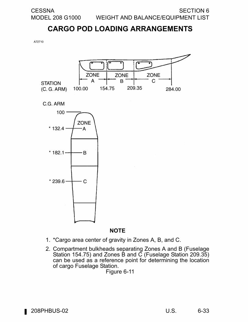
CESSNA SECTION 6MODEL 208 G1000 WEIGHT AND BALANCE/EQUIPMENT LIST
U.S. 6-33
CARGO POD LOADING ARRANGEMENTS
NOTE
1. *Cargo area center of gravity in Zones A, B, and C.
2. Compartment bulkheads separating Zones A and B (FuselageStation 154.75) and Zones B and C (Fuselage Station 209.35)can be used as a reference point for determining the locationof cargo Fuselage Station.
Figure 6-11
208PHBUS-02
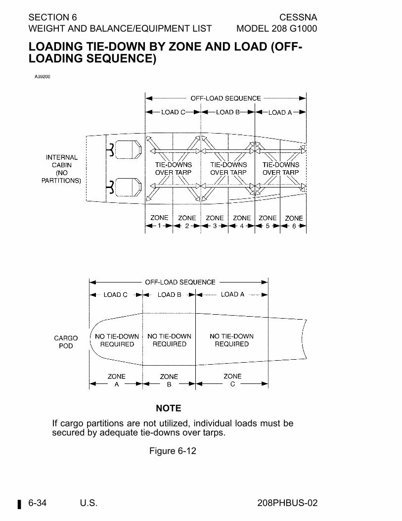
SECTION 6 CESSNAWEIGHT AND BALANCE/EQUIPMENT LIST MODEL 208 G1000
U.S.6-34
LOADING TIE-DOWN BY ZONE AND LOAD (OFF-LOADING SEQUENCE)
NOTE
If cargo partitions are not utilized, individual loads must besecured by adequate tie-downs over tarps.
Figure 6-12
208PHBUS-02
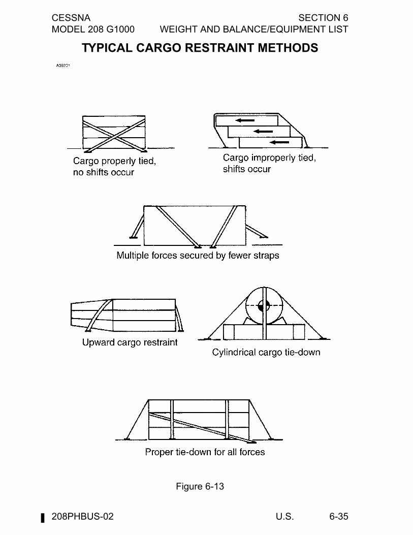
CESSNA SECTION 6MODEL 208 G1000 WEIGHT AND BALANCE/EQUIPMENT LIST
U.S. 6-35
TYPICAL CARGO RESTRAINT METHODS
Figure 6-13
208PHBUS-02
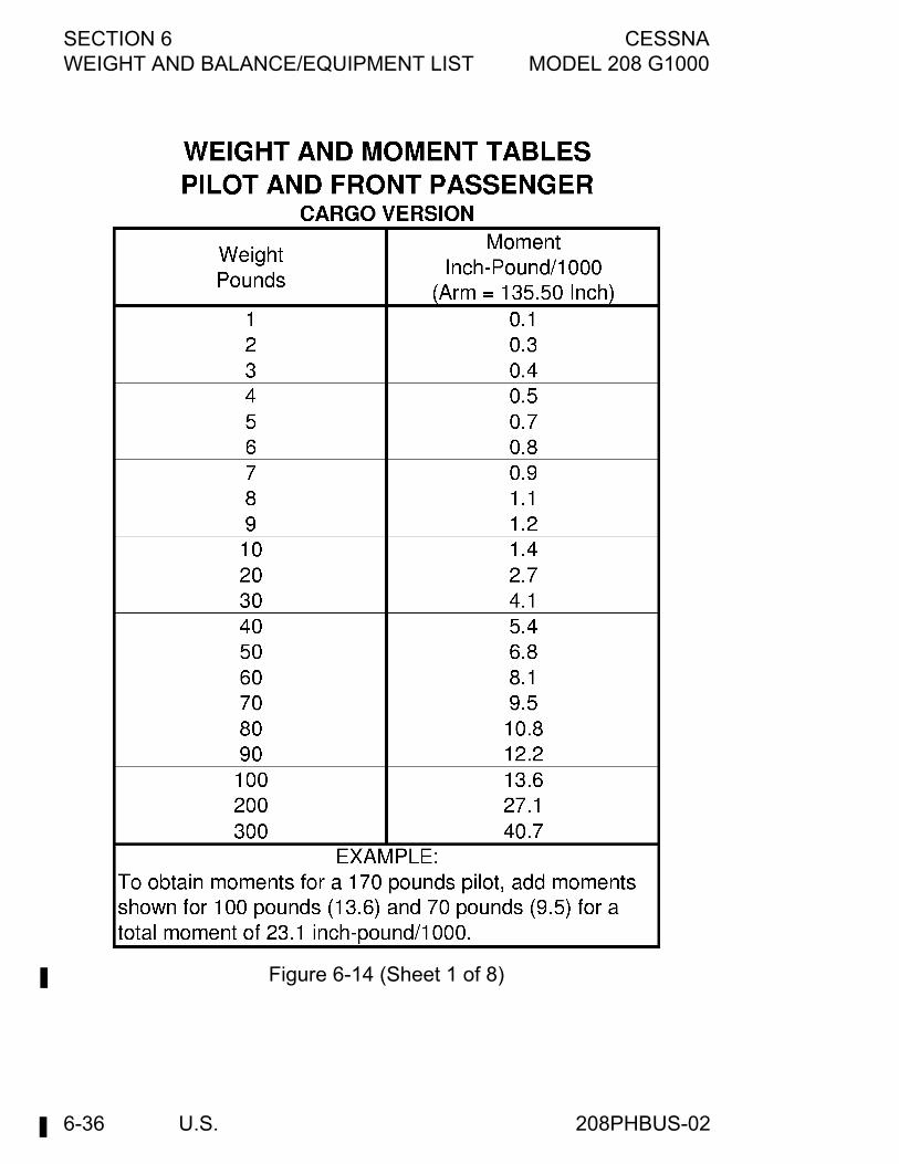
SECTION 6 CESSNAWEIGHT AND BALANCE/EQUIPMENT LIST MODEL 208 G1000
U.S.6-36
Figure 6-14 (Sheet 1 of 8)
208PHBUS-02
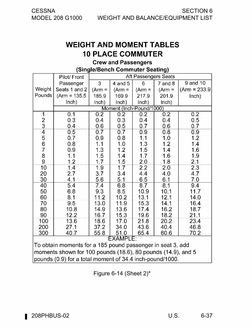
CESSNA SECTION 6MODEL 208 G1000 WEIGHT AND BALANCE/EQUIPMENT LIST
U.S. 6-37
Figure 6-14 (Sheet 2)*
208PHBUS-02
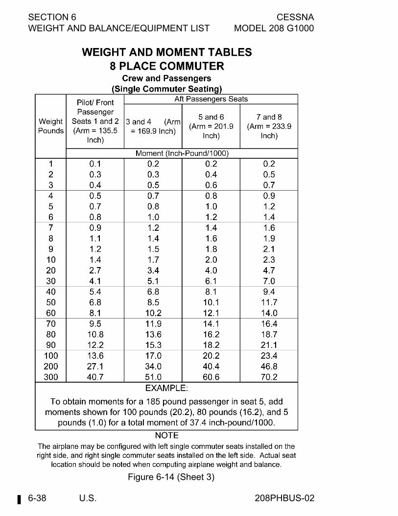
SECTION 6 CESSNAWEIGHT AND BALANCE/EQUIPMENT LIST MODEL 208 G1000
U.S.6-38
Figure 6-14 (Sheet 3)
208PHBUS-02
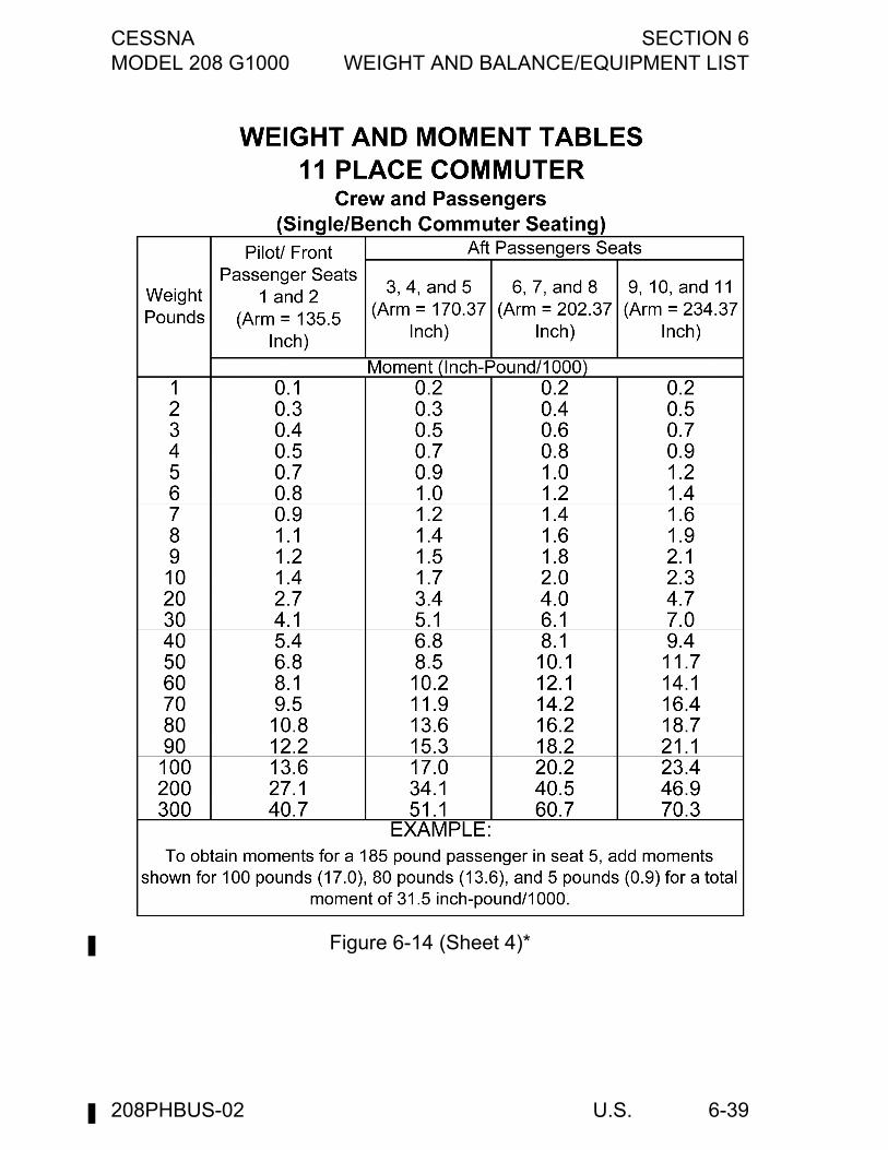
CESSNA SECTION 6MODEL 208 G1000 WEIGHT AND BALANCE/EQUIPMENT LIST
U.S. 6-39
Figure 6-14 (Sheet 4)*
208PHBUS-02
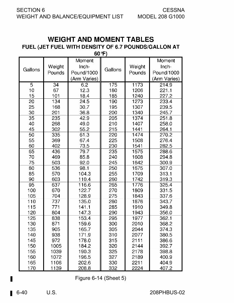
SECTION 6 CESSNAWEIGHT AND BALANCE/EQUIPMENT LIST MODEL 208 G1000
U.S.6-40
Figure 6-14 (Sheet 5)
208PHBUS-02
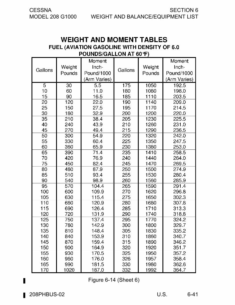
CESSNA SECTION 6MODEL 208 G1000 WEIGHT AND BALANCE/EQUIPMENT LIST
U.S. 6-41
Figure 6-14 (Sheet 6)
208PHBUS-02
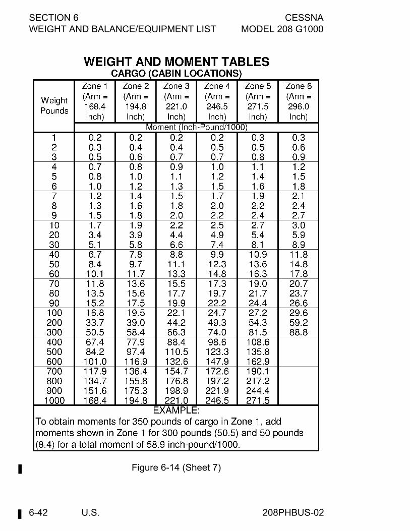
SECTION 6 CESSNAWEIGHT AND BALANCE/EQUIPMENT LIST MODEL 208 G1000
U.S.6-42
Figure 6-14 (Sheet 7)
208PHBUS-02
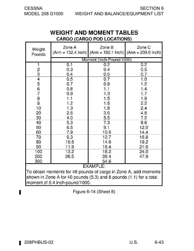
CESSNA SECTION 6MODEL 208 G1000 WEIGHT AND BALANCE/EQUIPMENT LIST
U.S. 6-43
Figure 6-14 (Sheet 8)
208PHBUS-02
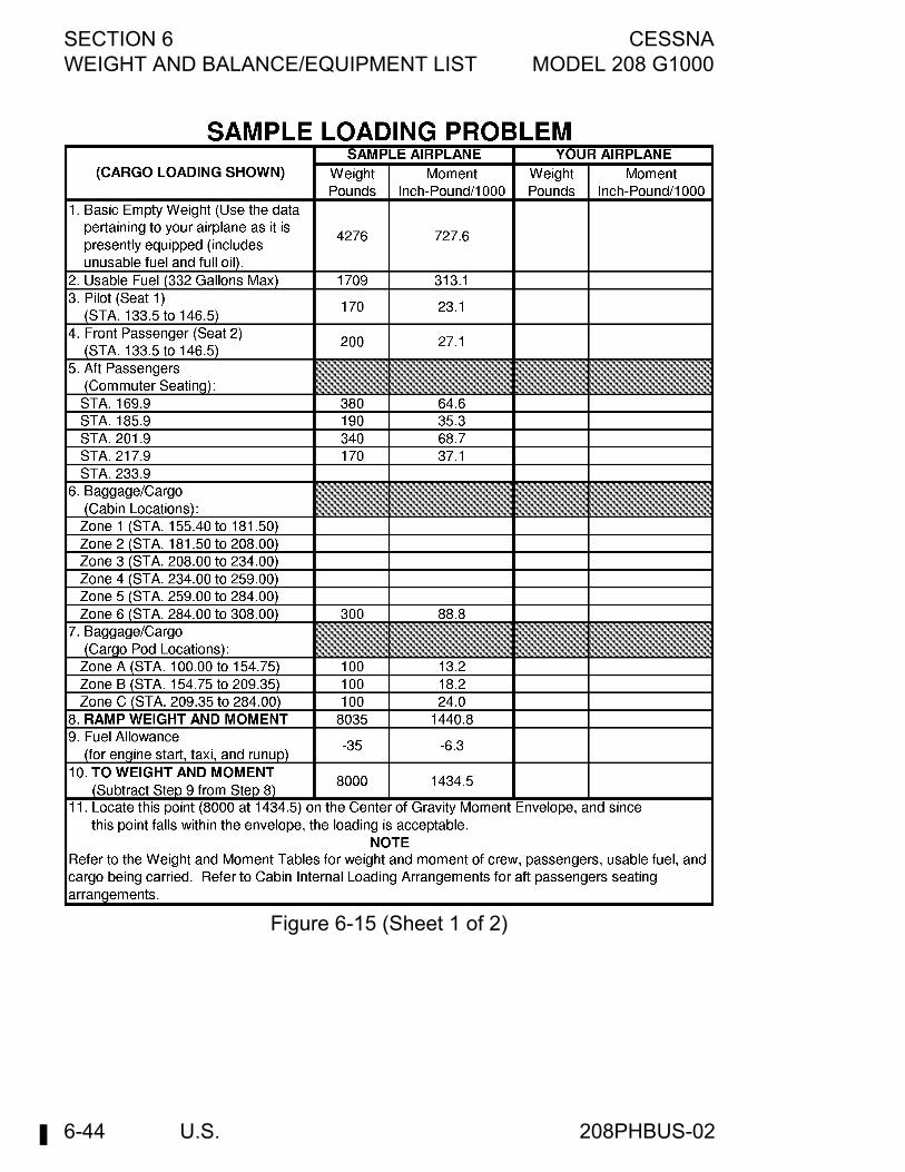
SECTION 6 CESSNAWEIGHT AND BALANCE/EQUIPMENT LIST MODEL 208 G1000
U.S.6-44
Figure 6-15 (Sheet 1 of 2)
208PHBUS-02

CESSNA SECTION 6MODEL 208 G1000 WEIGHT AND BALANCE/EQUIPMENT LIST
U.S. 6-45
Figure 6-15 (Sheet 2)
208PHBUS-02
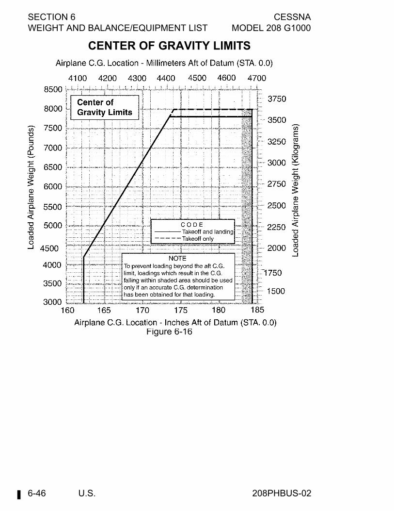
SECTION 6 CESSNAWEIGHT AND BALANCE/EQUIPMENT LIST MODEL 208 G1000
U.S.6-46
CENTER OF GRAVITY LIMITS
Figure 6-16
208PHBUS-02
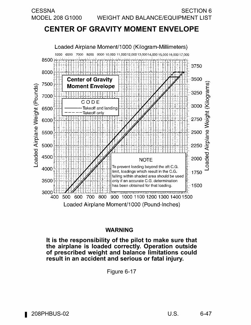
CESSNA SECTION 6MODEL 208 G1000 WEIGHT AND BALANCE/EQUIPMENT LIST
U.S. 6-47
CENTER OF GRAVITY MOMENT ENVELOPE
WARNING
It is the responsibility of the pilot to make sure thatthe airplane is loaded correctly. Operation outsideof prescribed weight and balance limitations couldresult in an accident and serious or fatal injury.
Figure 6-17
208PHBUS-02

SECTION 6 CESSNAWEIGHT AND BALANCE/EQUIPMENT LIST MODEL 208 G1000
U.S.6-48
This Page Intentionally Left Blank
208PHBUS-02
CESSNA SECTION 7MODEL 208 G1000 AIRPLANE AND SYSTEMS DESCRIPTION
U.S. 7-1
AIRPLANE & SYSTEMS DESCRIPTIONS
TABLE OF CONTENTSPage
Introduction . . . . . . . . . . . . . . . . . . . . . . . . . . . . . . . . . . . . . . . . . . . .7-7Airframe . . . . . . . . . . . . . . . . . . . . . . . . . . . . . . . . . . . . . . . . . . . . . . .7-7Cargo Pod . . . . . . . . . . . . . . . . . . . . . . . . . . . . . . . . . . . . . . . . . . . . .7-8Flight Controls . . . . . . . . . . . . . . . . . . . . . . . . . . . . . . . . . . . . . . . . . .7-9
Trim Systems . . . . . . . . . . . . . . . . . . . . . . . . . . . . . . . . . . . . . . . .7-9Flight Control and Trim System. . . . . . . . . . . . . . . . . . . . . . . . . .7-10
Instrument Panel . . . . . . . . . . . . . . . . . . . . . . . . . . . . . . . . . . . . . . .7-13Garmin Interfaces . . . . . . . . . . . . . . . . . . . . . . . . . . . . . . . . . . . .7-13Panel Layout . . . . . . . . . . . . . . . . . . . . . . . . . . . . . . . . . . . . . . . .7-14Control Pedestal . . . . . . . . . . . . . . . . . . . . . . . . . . . . . . . . . . . . .7-14Typical Instrument Panel. . . . . . . . . . . . . . . . . . . . . . . . . . . . . . .7-15Left Sidewall Switch and Circuit Breaker Panel . . . . . . . . . . . . .7-17Overhead Panel . . . . . . . . . . . . . . . . . . . . . . . . . . . . . . . . . . . . .7-17Overhead Panel . . . . . . . . . . . . . . . . . . . . . . . . . . . . . . . . . . . . .7-18Typical Left Sidewall Switch
and Circuit Breaker Panel . . . . . . . . . . . . . . . . . . . . . . . . . . . .7-19CAS Messages . . . . . . . . . . . . . . . . . . . . . . . . . . . . . . . . . . . . . . . .7-20Ground Control . . . . . . . . . . . . . . . . . . . . . . . . . . . . . . . . . . . . . . . .7-22
Minimum Turning Radius . . . . . . . . . . . . . . . . . . . . . . . . . . . . . .7-23Wing Flap System . . . . . . . . . . . . . . . . . . . . . . . . . . . . . . . . . . . . . .7-24Landing Gear System . . . . . . . . . . . . . . . . . . . . . . . . . . . . . . . . . . .7-25Baggage/Cargo Compartment . . . . . . . . . . . . . . . . . . . . . . . . . . . . .7-26Seats . . . . . . . . . . . . . . . . . . . . . . . . . . . . . . . . . . . . . . . . . . . . . . . .7-26
Pilot's and Copilot's Seats . . . . . . . . . . . . . . . . . . . . . . . . . . . . . .7-26Aft Passengers’ Seat (Commuter) (Passenger Version) . . . . . . .7-27Aft Passengers’ Seat (Utility) (Passenger Version) . . . . . . . . . . .7-27Headrests . . . . . . . . . . . . . . . . . . . . . . . . . . . . . . . . . . . . . . . . . .7-27Seat Belts and Shoulder Harnesses figure . . . . . . . . . . . . . . . . .7-28
Seat Belts and Shoulder Harnesses . . . . . . . . . . . . . . . . . . . . . . . .7-31Seat Belts, Strap, and Shoulder Harnesses (Pilot and Copilot’s
seats). . . . . . . . . . . . . . . . . . . . . . . . . . . . . . . . . . . . . . . . . . . .7-31Cabin Entry Doors . . . . . . . . . . . . . . . . . . . . . . . . . . . . . . . . . . . . . .7-33
Crew Entry Doors . . . . . . . . . . . . . . . . . . . . . . . . . . . . . . . . . . . .7-33Passenger Entry Door (Passenger Version Only). . . . . . . . . . . .7-34
(Continued Next Page)
208PHBUS-02
SECTION 7 CESSNAAIRPLANE AND SYSTEMS DESCRIPTION MODEL 208 G1000
U.S.7-2
TABLE OF CONTENTS (Continued)Page
Cargo Doors . . . . . . . . . . . . . . . . . . . . . . . . . . . . . . . . . . . . . . . . . . 7-37Cabin Windows . . . . . . . . . . . . . . . . . . . . . . . . . . . . . . . . . . . . . . . 7-39Control Locks . . . . . . . . . . . . . . . . . . . . . . . . . . . . . . . . . . . . . . . . . 7-39Engine . . . . . . . . . . . . . . . . . . . . . . . . . . . . . . . . . . . . . . . . . . . . . . 7-40
Typical Engine Components . . . . . . . . . . . . . . . . . . . . . . . . . . . 7-42Engine Controls . . . . . . . . . . . . . . . . . . . . . . . . . . . . . . . . . . . . . 7-43
Power Lever . . . . . . . . . . . . . . . . . . . . . . . . . . . . . . . . . . . . . . 7-43Emergency Power Lever . . . . . . . . . . . . . . . . . . . . . . . . . . . . 7-44Propeller Control Lever . . . . . . . . . . . . . . . . . . . . . . . . . . . . . 7-45Fuel Condition Lever . . . . . . . . . . . . . . . . . . . . . . . . . . . . . . . 7-45Quadrant Friction Lock. . . . . . . . . . . . . . . . . . . . . . . . . . . . . . 7-46
Engine Instrument System (EIS) . . . . . . . . . . . . . . . . . . . . . . . . 7-46Torque Indications . . . . . . . . . . . . . . . . . . . . . . . . . . . . . . . . . 7-47Propeller RPM Indications . . . . . . . . . . . . . . . . . . . . . . . . . . . 7-47ITT Indicator . . . . . . . . . . . . . . . . . . . . . . . . . . . . . . . . . . . . . . 7-47Gas Generator RPM Indications . . . . . . . . . . . . . . . . . . . . . . 7-47Fuel Flow Indications . . . . . . . . . . . . . . . . . . . . . . . . . . . . . . . 7-48Oil Pressure Indication . . . . . . . . . . . . . . . . . . . . . . . . . . . . . . 7-48Oil Temperature Gage . . . . . . . . . . . . . . . . . . . . . . . . . . . . . . 7-48
New Engine Break-In and Operation . . . . . . . . . . . . . . . . . . . . . . . 7-48Engine Lubrication System. . . . . . . . . . . . . . . . . . . . . . . . . . . . . . . 7-49Ignition System. . . . . . . . . . . . . . . . . . . . . . . . . . . . . . . . . . . . . . . . 7-50Air Induction System . . . . . . . . . . . . . . . . . . . . . . . . . . . . . . . . . . . 7-51Inertial Separator System. . . . . . . . . . . . . . . . . . . . . . . . . . . . . . . . 7-52
Engine Air Flow . . . . . . . . . . . . . . . . . . . . . . . . . . . . . . . . . . . . . 7-53Exhaust System . . . . . . . . . . . . . . . . . . . . . . . . . . . . . . . . . . . . . . . 7-54Engine Fuel System . . . . . . . . . . . . . . . . . . . . . . . . . . . . . . . . . . . . 7-54Cooling System . . . . . . . . . . . . . . . . . . . . . . . . . . . . . . . . . . . . . . . 7-55Starting System . . . . . . . . . . . . . . . . . . . . . . . . . . . . . . . . . . . . . . . 7-56Engine Accessories . . . . . . . . . . . . . . . . . . . . . . . . . . . . . . . . . . . . 7-56
Oil Pump . . . . . . . . . . . . . . . . . . . . . . . . . . . . . . . . . . . . . . . . . . 7-57Fuel Pump . . . . . . . . . . . . . . . . . . . . . . . . . . . . . . . . . . . . . . . . . 7-57Ng Tachometer-Generator . . . . . . . . . . . . . . . . . . . . . . . . . . . . . 7-57Propeller Tachometer-Generator . . . . . . . . . . . . . . . . . . . . . . . . 7-58Torquemeter. . . . . . . . . . . . . . . . . . . . . . . . . . . . . . . . . . . . . . . . 7-58Starter/Generator . . . . . . . . . . . . . . . . . . . . . . . . . . . . . . . . . . . . 7-58Interstage Turbine Temperature Sensing System . . . . . . . . . . . 7-58Propeller Governor . . . . . . . . . . . . . . . . . . . . . . . . . . . . . . . . . . 7-59
(Continued Next Page)
208PHBUS-02

CESSNA SECTION 7MODEL 208 G1000 AIRPLANE AND SYSTEMS DESCRIPTION
U.S. 7-3
TABLE OF CONTENTS (Continued)Page
Propeller Overspeed Governor . . . . . . . . . . . . . . . . . . . . . . . . . .7-59Engine Fire Detection System. . . . . . . . . . . . . . . . . . . . . . . . . . .7-60Engine Gear Reduction System . . . . . . . . . . . . . . . . . . . . . . . . .7-60Chip Detectors . . . . . . . . . . . . . . . . . . . . . . . . . . . . . . . . . . . . . .7-61Oil Breather Drain Can . . . . . . . . . . . . . . . . . . . . . . . . . . . . . . . .7-61
Propeller . . . . . . . . . . . . . . . . . . . . . . . . . . . . . . . . . . . . . . . . . . . . .7-61Propeller Anti-Ice Boots . . . . . . . . . . . . . . . . . . . . . . . . . . . . . . .7-62Overspeed Governor Test Switch . . . . . . . . . . . . . . . . . . . . . . . .7-64
Fuel System. . . . . . . . . . . . . . . . . . . . . . . . . . . . . . . . . . . . . . . . . . .7-64Fuel System Figure . . . . . . . . . . . . . . . . . . . . . . . . . . . . . . . . . . .7-66Fuel Quantity Data . . . . . . . . . . . . . . . . . . . . . . . . . . . . . . . . . . .7-67Firewall Fuel Shutoff Valve . . . . . . . . . . . . . . . . . . . . . . . . . . . . .7-68Fuel Tank Selectors. . . . . . . . . . . . . . . . . . . . . . . . . . . . . . . . . . .7-68Fuel Selectors Off Warning System . . . . . . . . . . . . . . . . . . . . . .7-68Fuel Boost Pump Switch . . . . . . . . . . . . . . . . . . . . . . . . . . . . . . .7-69Fuel Flow Indication . . . . . . . . . . . . . . . . . . . . . . . . . . . . . . . . . .7-70Fuel Quantity Indications. . . . . . . . . . . . . . . . . . . . . . . . . . . . . . .7-70Wing Tank Fuel Low CAS Message . . . . . . . . . . . . . . . . . . . . . .7-70Reservoir Fuel Low CAS Message . . . . . . . . . . . . . . . . . . . . . . .7-71Fuel Pressure Low Warning CAS Message . . . . . . . . . . . . . . . .7-71Fuel Boost Pump On CAS Message. . . . . . . . . . . . . . . . . . . . . .7-71Drain Valves . . . . . . . . . . . . . . . . . . . . . . . . . . . . . . . . . . . . . . . .7-71Fuel Drain Can . . . . . . . . . . . . . . . . . . . . . . . . . . . . . . . . . . . . . .7-72Fuel Pump Drain Reservoir. . . . . . . . . . . . . . . . . . . . . . . . . . . . .7-72
Brake System . . . . . . . . . . . . . . . . . . . . . . . . . . . . . . . . . . . . . . . . .7-73Electrical System . . . . . . . . . . . . . . . . . . . . . . . . . . . . . . . . . . . . . . .7-74
Standby Electrical System. . . . . . . . . . . . . . . . . . . . . . . . . . . . . .7-74Generator Control Unit . . . . . . . . . . . . . . . . . . . . . . . . . . . . . . . .7-75Ground Power Monitor . . . . . . . . . . . . . . . . . . . . . . . . . . . . . . . .7-75Battery Switch . . . . . . . . . . . . . . . . . . . . . . . . . . . . . . . . . . . . . . .7-75Starter Switch . . . . . . . . . . . . . . . . . . . . . . . . . . . . . . . . . . . . . . .7-76Ignition Switch . . . . . . . . . . . . . . . . . . . . . . . . . . . . . . . . . . . . . . .7-76Generator Switch . . . . . . . . . . . . . . . . . . . . . . . . . . . . . . . . . . . .7-76Standby Alternator Power Switch . . . . . . . . . . . . . . . . . . . . . . . .7-76Avionics Power Switches . . . . . . . . . . . . . . . . . . . . . . . . . . . . . .7-77Avionics Standby Power Switch . . . . . . . . . . . . . . . . . . . . . . . . .7-77Avionics Bus Tie Switch . . . . . . . . . . . . . . . . . . . . . . . . . . . . . . .7-77Typical Electrical System . . . . . . . . . . . . . . . . . . . . . . . . . . . . . .7-78
(Continued Next Page)
208PHBUS-02
SECTION 7 CESSNAAIRPLANE AND SYSTEMS DESCRIPTION MODEL 208 G1000
U.S.7-4
TABLE OF CONTENTS (Continued)Page
External Power Switch. . . . . . . . . . . . . . . . . . . . . . . . . . . . . . . . 7-81Circuit Breakers . . . . . . . . . . . . . . . . . . . . . . . . . . . . . . . . . . . . . 7-81Voltage and Amperage Display . . . . . . . . . . . . . . . . . . . . . . . . . 7-81Ground Service Plug Receptacle. . . . . . . . . . . . . . . . . . . . . . . . 7-82
Lighting Systems . . . . . . . . . . . . . . . . . . . . . . . . . . . . . . . . . . . . . . 7-82Exterior Lighting. . . . . . . . . . . . . . . . . . . . . . . . . . . . . . . . . . . . . 7-82
Navigation Lights . . . . . . . . . . . . . . . . . . . . . . . . . . . . . . . . . . 7-82Landing Lights . . . . . . . . . . . . . . . . . . . . . . . . . . . . . . . . . . . . 7-83Taxi/Recognition Lights . . . . . . . . . . . . . . . . . . . . . . . . . . . . . 7-83Strobe Lights . . . . . . . . . . . . . . . . . . . . . . . . . . . . . . . . . . . . . 7-83Flashing Beacon Light . . . . . . . . . . . . . . . . . . . . . . . . . . . . . . 7-84Courtesy Lights . . . . . . . . . . . . . . . . . . . . . . . . . . . . . . . . . . . 7-84
Interior Lighting . . . . . . . . . . . . . . . . . . . . . . . . . . . . . . . . . . . . . 7-84Garmin Displays, Optional ADF, and
HF Displays (if installed). . . . . . . . . . . . . . . . . . . . . . . . . . . 7-84Standby Indicator Control Knob. . . . . . . . . . . . . . . . . . . . . . . 7-85Switch/Circuit Breaker Panel Control Knob . . . . . . . . . . . . . . 7-85Circuit Breaker/Pedestal/Overhead Panel Knob . . . . . . . . . . 7-85Left Flood Lighting Control Knob . . . . . . . . . . . . . . . . . . . . . . 7-85Right Flood Lighting Control Knob. . . . . . . . . . . . . . . . . . . . . 7-85Control Wheel Maplight . . . . . . . . . . . . . . . . . . . . . . . . . . . . . 7-85Cabin Lights without Timer . . . . . . . . . . . . . . . . . . . . . . . . . . 7-86Cabin Lights with Timer (if installed) . . . . . . . . . . . . . . . . . . . 7-86Passenger Reading Lights (Passenger Version Only). . . . . . 7-86No Smoke/Seat Belt Sign (Passenger Version Only) . . . . . . 7-87
Cabin Heating, Ventilating And Defrosting System . . . . . . . . . . . . 7-87Bleed Air Heat Switch . . . . . . . . . . . . . . . . . . . . . . . . . . . . . . . . 7-88Temperature Selector Knob . . . . . . . . . . . . . . . . . . . . . . . . . . . . 7-88Cabin Heating, Ventilating and
Defrosting System (Cargo Version) figure . . . . . . . . . . . . . . . 7-89Mixing Air Push-Pull Control . . . . . . . . . . . . . . . . . . . . . . . . . . . 7-91Aft/Forward Cabin Push-Pull Control . . . . . . . . . . . . . . . . . . . . . 7-92Defrost/Forward Cabin Push-Pull Control . . . . . . . . . . . . . . . . . 7-92Cabin Heat Firewall Shutoff Knob . . . . . . . . . . . . . . . . . . . . . . . 7-92Vent Air Control Knobs . . . . . . . . . . . . . . . . . . . . . . . . . . . . . . . 7-93Instrument Panel Vent Knobs . . . . . . . . . . . . . . . . . . . . . . . . . . 7-93Ventilating Outlets . . . . . . . . . . . . . . . . . . . . . . . . . . . . . . . . . . . 7-93
Oxygen System . . . . . . . . . . . . . . . . . . . . . . . . . . . . . . . . . . . . . . . 7-93
(Continued Next Page)
208PHBUS-02
CESSNA SECTION 7MODEL 208 G1000 AIRPLANE AND SYSTEMS DESCRIPTION
U.S. 7-5
TABLE OF CONTENTS (Continued)Page
Pitot-Static System And Instruments . . . . . . . . . . . . . . . . . . . . . . . .7-94Airspeed Indicators . . . . . . . . . . . . . . . . . . . . . . . . . . . . . . . . . . .7-95Vertical Speed Indicators. . . . . . . . . . . . . . . . . . . . . . . . . . . . . . .7-95Altimeter (Standby Instrument Panel) . . . . . . . . . . . . . . . . . . . . .7-95
Vacuum System and Instruments . . . . . . . . . . . . . . . . . . . . . . . . . .7-96Attitude Indicator (Standby Instrument Panel). . . . . . . . . . . . . . .7-96Low-Vacuum Warning Flag . . . . . . . . . . . . . . . . . . . . . . . . . . . . .7-96Typical Vacuum System . . . . . . . . . . . . . . . . . . . . . . . . . . . . . . .7-97
Stall Warning System. . . . . . . . . . . . . . . . . . . . . . . . . . . . . . . . . . . .7-98Avionics Support Equipment . . . . . . . . . . . . . . . . . . . . . . . . . . . . . .7-99
Avionics Cooling Fan . . . . . . . . . . . . . . . . . . . . . . . . . . . . . . . . .7-99Microphone-Headset Installations . . . . . . . . . . . . . . . . . . . . . . .7-99Static Dischargers . . . . . . . . . . . . . . . . . . . . . . . . . . . . . . . . . . .7-10012 VDC Power Outlet . . . . . . . . . . . . . . . . . . . . . . . . . . . . . . . .7-100Auxiliary Audio Input Jack . . . . . . . . . . . . . . . . . . . . . . . . . . . . .7-101
Cabin Features . . . . . . . . . . . . . . . . . . . . . . . . . . . . . . . . . . . . . . .7-101Cabin Fire Extinguisher. . . . . . . . . . . . . . . . . . . . . . . . . . . . . . .7-101Sun Visors. . . . . . . . . . . . . . . . . . . . . . . . . . . . . . . . . . . . . . . . .7-102Chart and Storage Compartments. . . . . . . . . . . . . . . . . . . . . . .7-102
Miscellaneous Equipment . . . . . . . . . . . . . . . . . . . . . . . . . . . . . . .7-102Engine Inlet Covers and Propeller Anchors . . . . . . . . . . . . . . .7-102Crew Entry Step Assembly . . . . . . . . . . . . . . . . . . . . . . . . . . . .7-103Cargo Barrier and Nets . . . . . . . . . . . . . . . . . . . . . . . . . . . . . . .7-103Cargo Partitions . . . . . . . . . . . . . . . . . . . . . . . . . . . . . . . . . . . .7-103Cargo Door Restraining Net . . . . . . . . . . . . . . . . . . . . . . . . . . .7-103Cargo/Airplane Tie-down Equipment . . . . . . . . . . . . . . . . . . . .7-104Hoisting Rings . . . . . . . . . . . . . . . . . . . . . . . . . . . . . . . . . . . . . .7-104Relief Tube . . . . . . . . . . . . . . . . . . . . . . . . . . . . . . . . . . . . . . . .7-104Oil Quick-drain Valve. . . . . . . . . . . . . . . . . . . . . . . . . . . . . . . . .7-104
208PHBUS-02

SECTION 7 CESSNAAIRPLANE AND SYSTEMS DESCRIPTION MODEL 208 G1000
U.S.7-6
This Page Intentionally Left Blank
208PHBUS-02
CESSNA SECTION 7MODEL 208 G1000 AIRPLANE AND SYSTEMS DESCRIPTION
U.S. 7-7
INTRODUCTIONThis section provides description and operation of the airplane and itssystems. Refer to Section 9, Supplements for details of othersupplemental systems and equipment.
WARNING
Complete familiarity with the airplane and itssystems will not only increase the pilot'sproficiency and ensure optimum operation, butcould provide a basis for analyzing systemmalfunctions in case an emergency is encountered.Information in this section will assist in thatfamiliarization. The responsible pilot will want to beprepared to make proper and precise responses inevery situation.
AIRFRAMEThe airplane is an all-metal, high-wing, single-engine airplane equippedwith tricycle landing gear and designed for general utility purposes. Theconstruction of the fuselage is a conventional formed sheet metalbulkhead, stringer, and skin design referred to as semimonocoque.Major items of structure are the front and rear carry-through spars towhich the wings are attached, a bulkhead and forgings for main landinggear attachment and a bulkhead with attaching plates at its base for thestrut-to-fuselage attachment of the wing struts.The externally braced wings, having integral fuel tanks, are constructedof a front and rear spar with formed sheet metal ribs, doublers, andstringers. The entire structure is covered with aluminum skin. The frontspars are equipped with wing-to-fuselage and wing-to-strut attachfittings. The aft spars are equipped with wing-to-fuselage attach fittings.The integral fuel tanks are formed by the front and rear spars, upperand lower skins, and inboard and outboard closeout ribs. Extensive useof bonding is employed in the fuel tank area to reduce fuel tank sealing.Round-nosed ailerons and single-slot type flaps are made fromconventional formed sheet metal ribs and smooth aluminum skinconstruction. A slot lip spoiler, mounted above the outboard end ofeach flap, is of conventional construction. The left aileron incorporatesa servo tab while the right aileron incorporates a trimmable servo tab,both mounted on the outboard end of the aileron trailing edge.
(Continued Next Page)
208PHBUS-00
SECTION 7 CESSNAAIRPLANE AND SYSTEMS DESCRIPTION MODEL 208 G1000
U.S.7-8
AIRFRAME (Continued)
The empennage (tail assembly) consists of a conventional verticalstabilizer, rudder, horizontal stabilizer, and elevator. The verticalstabilizer consists of a forward and aft spar, sheet metal ribs andreinforcements, four skin panels, formed leading edge skins, and adorsal fin. The rudder is constructed of a forward and aft spar, formedsheet metal ribs and reinforcements, and a wrap-around skin panel.The top of the rudder incorporates a leading edge extension whichcontains a balance weight. The horizontal stabilizer is constructed of aforward and aft spar, ribs and stiffeners, four upper and four lower skinpanels, and two left and two right wrap-around skin panels which alsoform the leading edges. The horizontal stabilizer also contains dual jackscrew type actuators for the elevator trim tabs. Construction of theelevator consists of a forward and aft spar, sheet metal ribs, upper andlower skin panels, and wrap-around skin panels for the leading andtrailing edges. An elevator trim tab is attached to the trailing edge ofeach elevator by full length piano-type hinges. Dual pushrods fromeach actuator located in the horizontal stabilizer transmit actuatormovement to dual horns on each elevator trim tab to provide tabmovement. Both elevator tip leading edge extensions provideaerodynamic balance and incorporate balance weights. A row of vortexgenerators on the top of the horizontal stabilizer just forward of theelevator enhances nose down elevator and trim authority.To assure extended service life of the airplane, the entire airframe iscorrosion proofed. Internally, all assemblies and sub-assemblies arecoated with a chemical film conversion coating and are then epoxyprimed. Steel parts in contact with aluminum structure are given achromate dip before assembly. Externally, the complete airframe ispainted with an overall coat of polyurethane paint which enhancesresistance to corrosive elements in the atmosphere. Also, all controlcables for the flight control system are of stainless steel construction.
CARGO PODThe airplane may be equipped with a cargo pod which providesadditional cargo space. The pod attaches to the bottom of the fuselagewith screws and can be removed, if desired, for increased performanceand useful load. The pod is fabricated with a Nomex inner housing, alayer of Kevlar, and an outer layer of fiberglass. Complete instructionsfor removal and installation of the cargo pod are contained in theMaintenance Manual.
(Continued Next Page)
208PHBUS-00
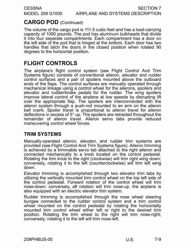
CESSNA SECTION 7MODEL 208 G1000 AIRPLANE AND SYSTEMS DESCRIPTION
U.S. 7-9
CARGO POD (Continued)
The volume of the cargo pod is 111.5 cubic feet and has a load-carryingcapacity of 1090 pounds. The pod has aluminum bulkheads that divideit into four separate compartments. Each compartment has a door onthe left side of the pod that is hinged at the bottom. Each door has twohandles that latch the doors in the closed position when rotated 90degrees to the horizontal position.
FLIGHT CONTROLSThe airplane's flight control system (see Flight Control And TrimSystems figure) consists of conventional aileron, elevator and ruddercontrol surfaces and a pair of spoilers mounted above the outboardends of the flaps. The control surfaces are manually operated throughmechanical linkage using a control wheel for the ailerons, spoilers andelevator and rudder/brake pedals for the rudder. The wing spoilersimprove lateral control of the airplane at low speeds by disrupting liftover the appropriate flap. The spoilers are interconnected with theaileron system through a push-rod mounted to an arm on the aileronbell crank. Spoiler travel is proportional to aileron travel for ailerondeflections in excess of 5° up. The spoilers are retracted throughout theremainder of aileron travel. Aileron servo tabs provide reducedmaneuvering control wheel forces.
TRIM SYSTEMSManually-operated aileron, elevator, and rudder trim systems areprovided (see Flight Control And Trim Systems figure). Aileron trimmingis achieved by a trimmable servo tab attached to the right aileron andconnected mechanically to a knob located on the control pedestal.Rotating the trim knob to the right (clockwise) will trim right wing down;conversely, rotating it to the left (counterclockwise) will trim left wingdown.Elevator trimming is accomplished through two elevator trim tabs byutilizing the vertically mounted trim control wheel on the top left side ofthe control pedestal. Forward rotation of the control wheel will trimnose-down; conversely, aft rotation will trim nose-up. the airplane isalso equipped with an electric elevator trim system. Rudder trimming is accomplished through the nose wheel steeringbungee connected to the rudder control system and a trim controlwheel mounted on the control pedestal by rotating the horizontallymounted trim control wheel either left or right to the desired trimposition. Rotating the trim wheel to the right will trim nose-right;conversely; rotating it to the left will trim nose-left.
208PHBUS-00
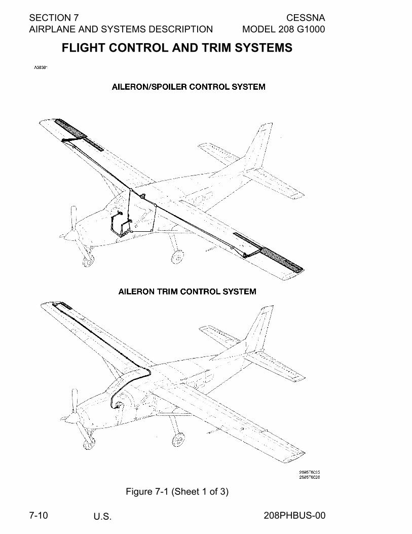
SECTION 7 CESSNAAIRPLANE AND SYSTEMS DESCRIPTION MODEL 208 G1000
U.S.7-10
FLIGHT CONTROL AND TRIM SYSTEMS
Figure 7-1 (Sheet 1 of 3)
208PHBUS-00
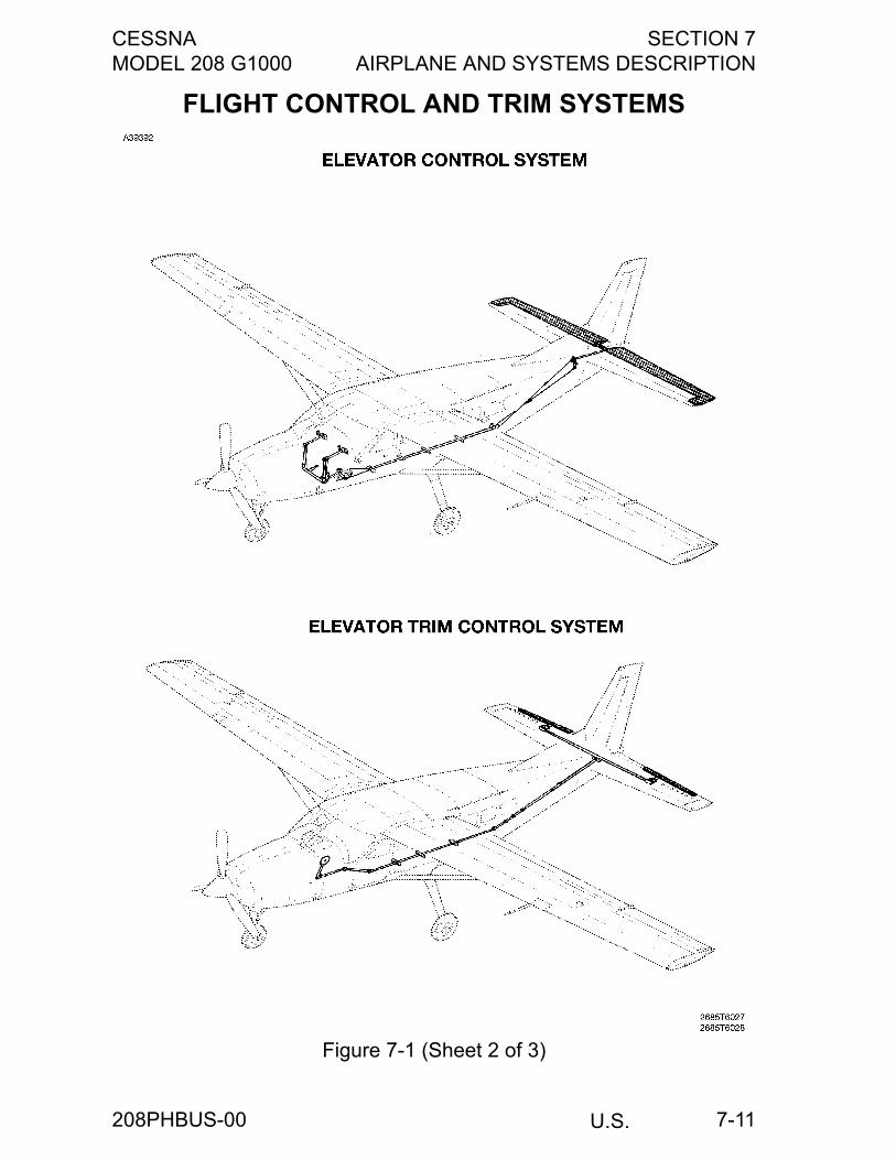
CESSNA SECTION 7MODEL 208 G1000 AIRPLANE AND SYSTEMS DESCRIPTION
U.S. 7-11
FLIGHT CONTROL AND TRIM SYSTEMS
Figure 7-1 (Sheet 2 of 3)
208PHBUS-00
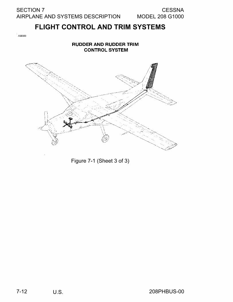
SECTION 7 CESSNAAIRPLANE AND SYSTEMS DESCRIPTION MODEL 208 G1000
U.S.7-12
FLIGHT CONTROL AND TRIM SYSTEMS
Figure 7-1 (Sheet 3 of 3)
208PHBUS-00
CESSNA SECTION 7MODEL 208 G1000 AIRPLANE AND SYSTEMS DESCRIPTION
U.S. 7-13
INSTRUMENT PANELThe instrument panel is designed around the Garmin G1000 IntegratedAvionics System. The instrument panel is of all metal construction andis installed in sections so equipment can be easily removed formaintenance. Equipment mounted on this panel is illustrated in theTypical Instrument Panel figure. Additional controls and displays aremounted on a pedestal extending from the center of the instrumentpanel to the floor, on a separate panel mounted on the left sidewall, andon an overhead panel.
GARMIN INTERFACESThe interfaces to the Garmin system are three Garmin Display Units(GDUs), an audio panel, and an autopilot mode controller. The threeGDUs are configured as two Primary Flight Displays (PFDs) and oneMultifunction Flight Display (MFD). Refer to the Garmin G1000 CRG forspecific operating information on all Garmin equipment.The PFDs, centered above the yokes in front of the pilot and copilot,show the primary flight instruments and display any Crew Alert System(CAS) messages and alerts. During reversionary operation (MFD orPFD 1 failure) or when the DISPLAY BACKUP switch is selected, theEngine Indication System (EIS) is shown on the PFD. The MFD, located between the two PFDs, depicts EIS informationalong the left side of the display and shows navigation, terrain, lightningand traffic data on the moving map. Flight management or displayconfiguration information can be shown on the MFD in place of themoving map pages.The Garmin audio panel is located between the pilot PFD and the MFD.It integrates all of the communication and navigation digital audiosignals, intercom system and marker beacon controls. A pushbuttonswitch labeled DISPLAY BACKUP allows manual selection ofreversionary mode for the PFDs and MFD.The Garmin autopilot mode controller, located above the MFD, is thepilot interface with the autopilot system.
208PHBUS-00
SECTION 7 CESSNAAIRPLANE AND SYSTEMS DESCRIPTION MODEL 208 G1000
U.S.7-14
PANEL LAYOUTTo the left of the pilot PFD is a switch panel which has many of theswitches necessary to operate the airplane systems. At lower left are acircuit breaker panel for avionics systems, the left fresh air outlet andpull knob, test switches for prop overspeed, fire detection, and fuelselection warning systems, microphone and headset jacks and analternate static source valve.Below the MFD are standby indicators for airspeed, attitude, altitude,and torque. Below these indicators are the parking brake, light dimmingcontrols, inertial separator control, and cabin heat controls. Provisionsare included for optional air conditioning controls and HF and ADFdisplays.At lower right are the map compartment, right fresh air outlet and pullknob, and microphone and headset jacks. At upper right are the hourmeter and ELT remote switch. Mounted above the glare shield is amagnetic compass. For details concerning the instruments, switches,and controls on this panel, refer in this section to the description of thesystems to which these items are related.
CONTROL PEDESTALA control pedestal, extending from the center of the instrument panel tothe floor, contains the EMERGENCY POWER Lever, power lever,PROP RPM Lever, FUEL CONDITION Lever, WING FLAP selector andposition indicator, elevator, rudder and aileron trim controls withposition indicators, the fuel shutoff valve control, cabin heat firewallshutoff valve control, a microphone, 12VDC power outlet, and anauxiliary audio input jackEquipment mounted on this panel is illustrated in the Typical InstrumentPanel figure. For details concerning the instruments, switches, andcontrols on the pedestal, refer in this section to the description of thesystems to which these items are related.
208PHBUS-00
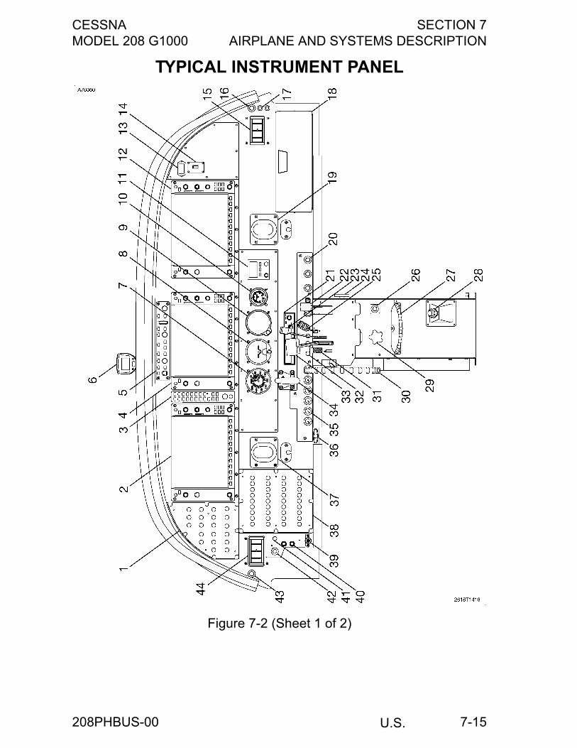
CESSNA SECTION 7MODEL 208 G1000 AIRPLANE AND SYSTEMS DESCRIPTION
U.S. 7-15
TYPICAL INSTRUMENT PANEL
Figure 7-2 (Sheet 1 of 2)
208PHBUS-00
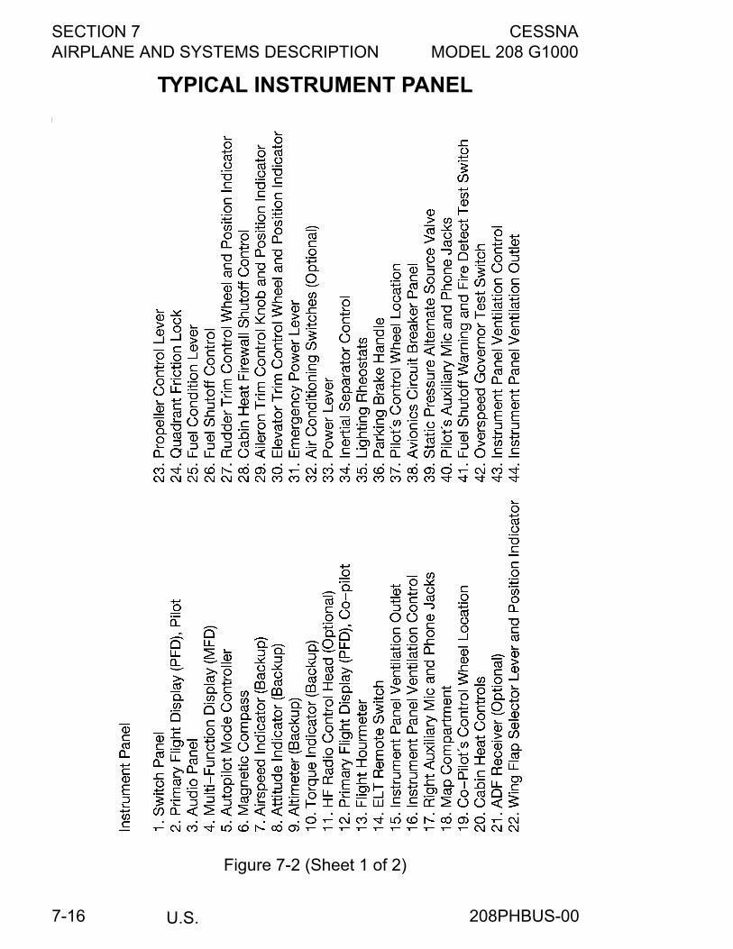
SECTION 7 CESSNAAIRPLANE AND SYSTEMS DESCRIPTION MODEL 208 G1000
U.S.7-16
TYPICAL INSTRUMENT PANEL
Figure 7-2 (Sheet 1 of 2)
208PHBUS-00
CESSNA SECTION 7MODEL 208 G1000 AIRPLANE AND SYSTEMS DESCRIPTION
U.S. 7-17
LEFT SIDEWALL SWITCH AND CIRCUIT BREAKERPANELMost of the engine control switches and non-avionics circuit breakersare located on a separate panel mounted on the left cabin sidewalladjacent to the pilot. Switches and controls on this panel are illustratedin the Typical Left Sidewall Switch and Circuit Breaker Panel figure. Fordetails concerning the instruments, switches, and controls on thispanel, refer to the ELECTRICAL EQUIPMENT descriptions in thissection.
OVERHEAD PANELThe overhead panel, located above and between the pilot and copilot,contains fuel selector controls, oxygen control and pressure gage, ventoutlets and controls, overhead lighting, and standby flap controls.Equipment mounted on this panel is illustrated in the Overhead Panelfigure. For details concerning the instruments, switches, and controlson the overhead panel, refer in this section to the description of thesystems to which these items are related.
208PHBUS-00
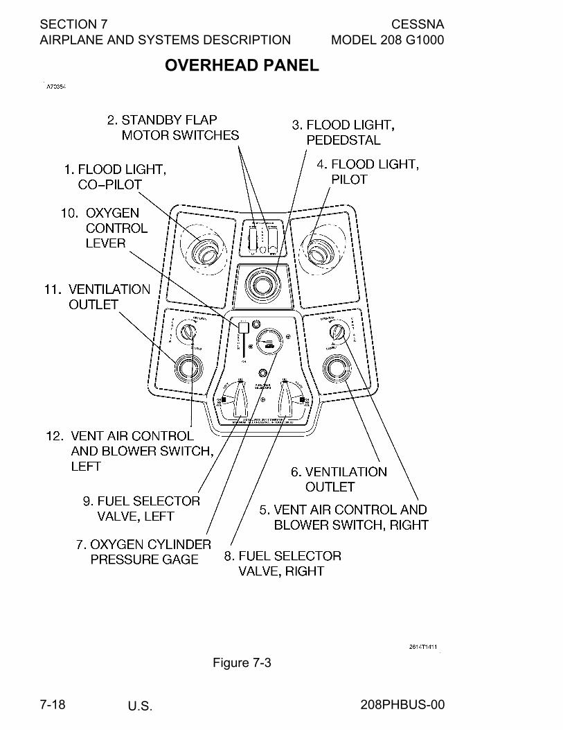
SECTION 7 CESSNAAIRPLANE AND SYSTEMS DESCRIPTION MODEL 208 G1000
U.S.7-18
OVERHEAD PANEL
Figure 7-3
208PHBUS-00

CESSNA SECTION 7MODEL 208 G1000 AIRPLANE AND SYSTEMS DESCRIPTION
U.S. 7-19
TYPICAL LEFT SIDEWALL SWITCH AND CIRCUIT BREAKER PANEL
Figure 7-4
208PHBUS-00
SECTION 7 CESSNAAIRPLANE AND SYSTEMS DESCRIPTION MODEL 208 G1000
U.S.7-20
CAS MESSAGES1. OIL PRESS LOW (RED) - Indicates engine oil pressure is less
than 40 psi.2. VOLTAGE LOW (RED) - Indicates electrical system bus voltage
is 24.5 volts or less and power is being supplied from the battery.3. VOLTAGE HIGH (RED) - Indicates electrical system bus voltage
is greater than 32.0 volts.
4. ENGINE FIRE (RED) - Indicates an excessive temperaturecondition and/or fire has occurred in the engine compartment.
5. RSVR FUEL LOW (RED) - Indicates the fuel level in the reservoirtank is approximately one-half or less. With the fuel reservoir full,there is adequate fuel for approximately 3 minutes of maximumcontinuous power or approximately 9 minutes at idle power.
6. EMERG PWR LVR (RED) - Indicates when the EmergencyPower Lever is out of the stowed (Normal) position prior to andduring the engine start (ITT in the OFF and STRT modes ONLY).
7. FUEL SELECT OFF (RED) - Indicates left and right fuel selectorsare both OFF at any time, or left fuel selector is OFF when righttank is low, or right fuel selector is OFF when the left tank is low;or that either left or right selectors are OFF when starter switch isON. It can also indicate that the FUEL SEL WARN circuit breakerhas been pulled.
8. GENERATOR OFF (AMBER) - Indicates that the generator is notconnected to the aircraft bus.
9. DOOR UNLATCHED (AMBER) - Indicates the upper cargo doorand/or upper aft passenger door (passenger version only) are notlatched.
10.L FUEL LEVEL LOW (AMBER) - Indicates fuel quantity in the leftfuel tank is 25 gallons (170 lbs) or less.
(Continued Next Page)
208PHBUS-02
CESSNA SECTION 7MODEL 208 G1000 AIRPLANE AND SYSTEMS DESCRIPTION
U.S. 7-21
CAS MESSAGES (Continued)
11.R FUEL LEVEL LOW (AMBER) - Indicates fuel quantity in theright fuel tank is 25 gallons (170 lbs) or less.
12.L-R FUEL LEVEL LOW (AMBER) Indicates fuel quantity in boththe left and right fuel tanks is 25 gallons (170 lbs) or less.
13.FUEL BOOST ON (AMBER) - Indicates the auxiliary fuel pump isoperating.
14.STBY PWR INOP (AMBER) - Indicates electrical power is notavailable from the standby alternator.
15.PROP DE-ICE (AMBER) - Indicates that one or more propellerblades are not heating, there is a malfunction in the monitoringsystem, or that the PROP ANTI-ICE circuit breaker is pulled.
16.FUEL PRESS LOW (AMBER) - Indicates fuel pressure in the fuelmanifold assembly is below 4.75 psi.
17.STARTER ON (AMBER) - Indicates the starter-generator isoperating in starter mode.
18.CHIP DETECT (AMBER) Indicates that metal chips have beendetected in either or both the accessory gearbox or reductiongearbox.
19.L P/S HEAT (AMBER) - Indicates that either the left side pitot/static vane heater system has malfunctioned or that the LEFTPITOT HEAT circuit breaker is pulled.
20.R P/S HEAT (AMBER) - Indicates that either the right side pitot/static vane heater system has malfunctioned or that the RIGHTPITOT HEAT circuit breaker is pulled.
21.L-R P/S HEAT (AMBER) - Indicates that either both pitot/staticvane heater systems (left and right) have malfunctioned or thatboth the LEFT and RIGHT PITOT HEAT circuit breakers arepulled.
22.STALL HEAT (AMBER) - Indicates that the stall warning heatersystem has malfunctioned or the STALL WARN circuit breaker ispulled in conditions below 19°C (66°F) or above 52°C (125°F).
(Continued Next Page)
208PHBUS-01
SECTION 7 CESSNAAIRPLANE AND SYSTEMS DESCRIPTION MODEL 208 G1000
U.S.7-22
CAS MESSAGES (Continued)
23.GENERATOR AMPS (AMBER) - Indicates that the generatoroutput is less than -10 amps or greater than 200 amps (-15/300with 300 amp starter generator).
24.ALTNR AMPS (AMBER) - Indicates that the alternator output isless than -10 amps or greater than 75 amps.
25.IGNITION ON (WHITE) - Indicates electrical power is beingsupplied to the engine ignition system.
26.STBY PWR ON (WHITE) - Indicates that the standby alternator isgenerating electrical power.
27.SPD NOT AVAIL (WHITE) - Indicates that the “SPD” key waspressed on Autopilot Mode Control panel.
GROUND CONTROL
Effective ground control while taxiing is accomplished through nosewheel steering by using the rudder pedals; left rudder pedal to steer leftand right rudder pedal to steer right. When a rudder pedal isdepressed, a spring-loaded steering bungee (which is connected to thenose gear and to the rudder bars) will turn the nose wheel through anarc of approximately 15° each side of center. By applying either left orright brake, the degree of turn may be increased up to 51.5°.
Moving the airplane by hand is most easily accomplished by attachinga tow bar (stowed in aft cargo compartment) to the nose gear fork axleholes. If a tow bar is not available, or pushing is required, use the wingstruts as push points. Do not use the propeller blades or spinner topush or pull the airplane. If the airplane is to be towed by vehicle, neverturn the nose wheel beyond the steering limit marks either side ofcenter. If excess force is exerted beyond the turning limit, a red over-travel indicator block (frangible stop) will fracture and the block,attached to a cable, will fall into view alongside the nose strut. Thisshould be checked routinely during preflight inspection to preventoperation with a damaged nose gear.
The minimum turning radius of the airplane, using differential brakingand nose wheel steering during taxi, is as shown in the MinimumTurning Radius figure.
208PHBUS-00
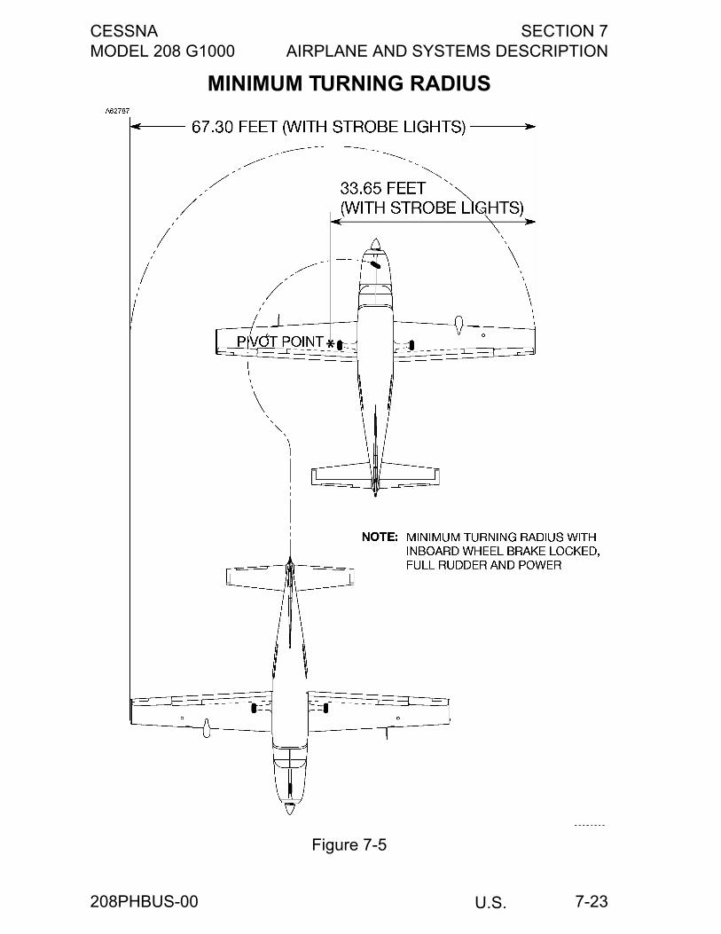
CESSNA SECTION 7MODEL 208 G1000 AIRPLANE AND SYSTEMS DESCRIPTION
U.S. 7-23
MINIMUM TURNING RADIUS
Figure 7-5
208PHBUS-00
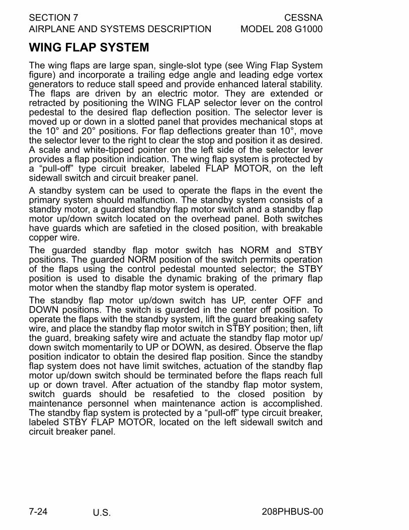
SECTION 7 CESSNAAIRPLANE AND SYSTEMS DESCRIPTION MODEL 208 G1000
U.S.7-24
WING FLAP SYSTEM
The wing flaps are large span, single-slot type (see Wing Flap Systemfigure) and incorporate a trailing edge angle and leading edge vortexgenerators to reduce stall speed and provide enhanced lateral stability.The flaps are driven by an electric motor. They are extended orretracted by positioning the WING FLAP selector lever on the controlpedestal to the desired flap deflection position. The selector lever ismoved up or down in a slotted panel that provides mechanical stops atthe 10° and 20° positions. For flap deflections greater than 10°, movethe selector lever to the right to clear the stop and position it as desired.A scale and white-tipped pointer on the left side of the selector leverprovides a flap position indication. The wing flap system is protected bya “pull-off” type circuit breaker, labeled FLAP MOTOR, on the leftsidewall switch and circuit breaker panel.A standby system can be used to operate the flaps in the event theprimary system should malfunction. The standby system consists of astandby motor, a guarded standby flap motor switch and a standby flapmotor up/down switch located on the overhead panel. Both switcheshave guards which are safetied in the closed position, with breakablecopper wire. The guarded standby flap motor switch has NORM and STBYpositions. The guarded NORM position of the switch permits operationof the flaps using the control pedestal mounted selector; the STBYposition is used to disable the dynamic braking of the primary flapmotor when the standby flap motor system is operated.The standby flap motor up/down switch has UP, center OFF andDOWN positions. The switch is guarded in the center off position. Tooperate the flaps with the standby system, lift the guard breaking safetywire, and place the standby flap motor switch in STBY position; then, liftthe guard, breaking safety wire and actuate the standby flap motor up/down switch momentarily to UP or DOWN, as desired. Observe the flapposition indicator to obtain the desired flap position. Since the standbyflap system does not have limit switches, actuation of the standby flapmotor up/down switch should be terminated before the flaps reach fullup or down travel. After actuation of the standby flap motor system,switch guards should be resafetied to the closed position bymaintenance personnel when maintenance action is accomplished.The standby flap system is protected by a “pull-off” type circuit breaker,labeled STBY FLAP MOTOR, located on the left sidewall switch andcircuit breaker panel.
208PHBUS-00
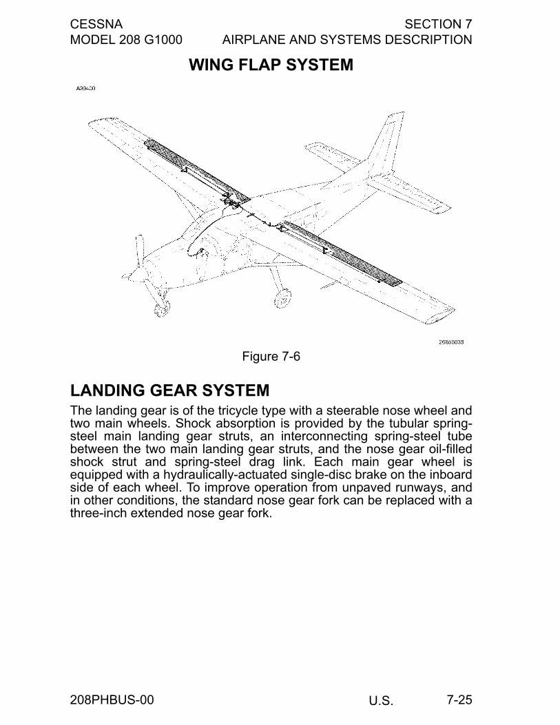
CESSNA SECTION 7MODEL 208 G1000 AIRPLANE AND SYSTEMS DESCRIPTION
U.S. 7-25
WING FLAP SYSTEM
LANDING GEAR SYSTEMThe landing gear is of the tricycle type with a steerable nose wheel andtwo main wheels. Shock absorption is provided by the tubular spring-steel main landing gear struts, an interconnecting spring-steel tubebetween the two main landing gear struts, and the nose gear oil-filledshock strut and spring-steel drag link. Each main gear wheel isequipped with a hydraulically-actuated single-disc brake on the inboardside of each wheel. To improve operation from unpaved runways, andin other conditions, the standard nose gear fork can be replaced with athree-inch extended nose gear fork.
Figure 7-6
208PHBUS-00
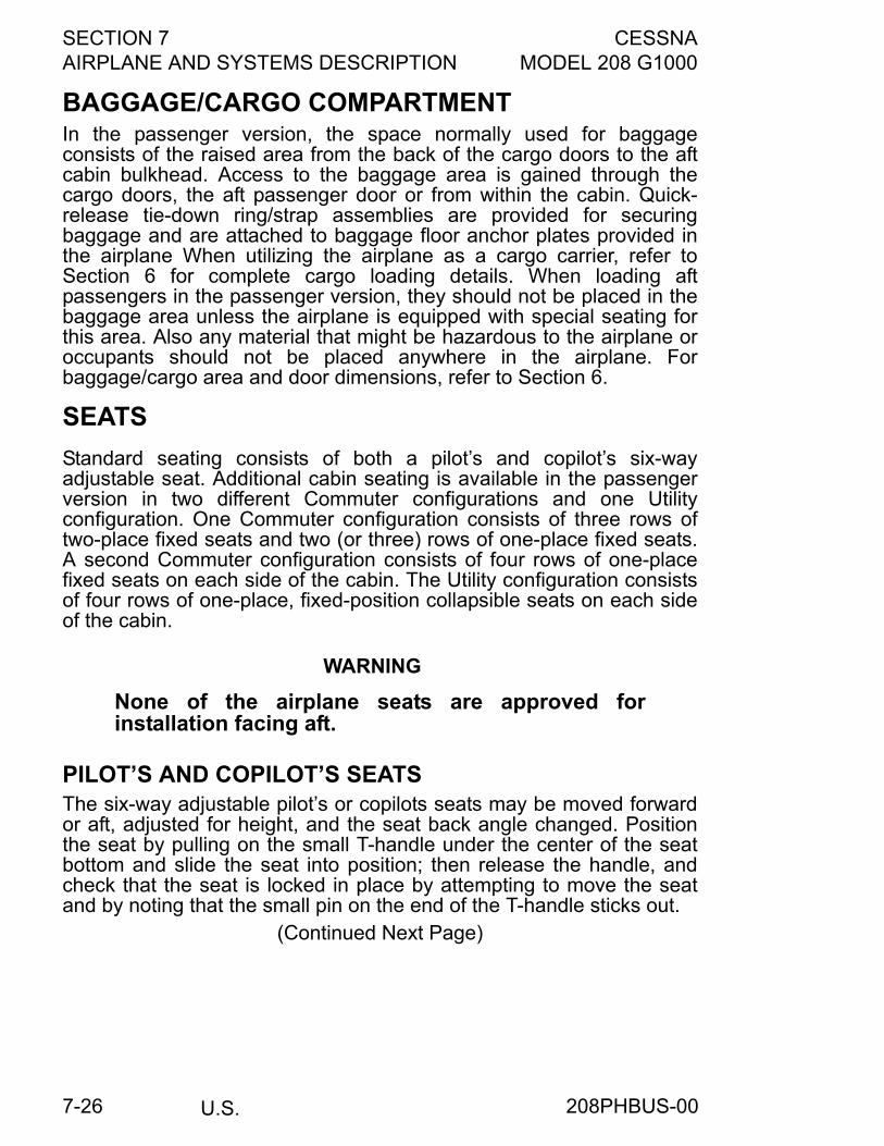
SECTION 7 CESSNAAIRPLANE AND SYSTEMS DESCRIPTION MODEL 208 G1000
U.S.7-26
BAGGAGE/CARGO COMPARTMENTIn the passenger version, the space normally used for baggageconsists of the raised area from the back of the cargo doors to the aftcabin bulkhead. Access to the baggage area is gained through thecargo doors, the aft passenger door or from within the cabin. Quick-release tie-down ring/strap assemblies are provided for securingbaggage and are attached to baggage floor anchor plates provided inthe airplane When utilizing the airplane as a cargo carrier, refer toSection 6 for complete cargo loading details. When loading aftpassengers in the passenger version, they should not be placed in thebaggage area unless the airplane is equipped with special seating forthis area. Also any material that might be hazardous to the airplane oroccupants should not be placed anywhere in the airplane. Forbaggage/cargo area and door dimensions, refer to Section 6.
SEATS
Standard seating consists of both a pilot’s and copilot’s six-wayadjustable seat. Additional cabin seating is available in the passengerversion in two different Commuter configurations and one Utilityconfiguration. One Commuter configuration consists of three rows oftwo-place fixed seats and two (or three) rows of one-place fixed seats.A second Commuter configuration consists of four rows of one-placefixed seats on each side of the cabin. The Utility configuration consistsof four rows of one-place, fixed-position collapsible seats on each sideof the cabin.
WARNING
None of the airplane seats are approved forinstallation facing aft.
PILOT’S AND COPILOT’S SEATSThe six-way adjustable pilot’s or copilots seats may be moved forwardor aft, adjusted for height, and the seat back angle changed. Positionthe seat by pulling on the small T-handle under the center of the seatbottom and slide the seat into position; then release the handle, andcheck that the seat is locked in place by attempting to move the seatand by noting that the small pin on the end of the T-handle sticks out.
(Continued Next Page)
208PHBUS-00
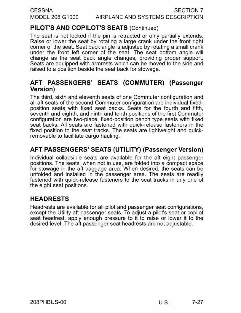
CESSNA SECTION 7MODEL 208 G1000 AIRPLANE AND SYSTEMS DESCRIPTION
U.S. 7-27
PILOT'S AND COPILOT'S SEATS (Continued)
The seat is not locked if the pin is retracted or only partially extends.Raise or lower the seat by rotating a large crank under the front rightcorner of the seat. Seat back angle is adjusted by rotating a small crankunder the front left corner of the seat. The seat bottom angle willchange as the seat back angle changes, providing proper support.Seats are equipped with armrests which can be moved to the side andraised to a position beside the seat back for stowage.
AFT PASSENGERS’ SEATS (COMMUTER) (PassengerVersion)The third, sixth and eleventh seats of one Commuter configuration andall aft seats of the second Commuter configuration are individual fixed-position seats with fixed seat backs. Seats for the fourth and fifth,seventh and eighth, and ninth and tenth positions of the first Commuterconfiguration are two-place, fixed-position bench type seats with fixedseat backs. All seats are fastened with quick-release fasteners in thefixed position to the seat tracks. The seats are lightweight and quick-removable to facilitate cargo hauling.
AFT PASSENGERS’ SEATS (UTILITY) (Passenger Version)Individual collapsible seats are available for the aft eight passengerpositions. The seats, when not in use, are folded into a compact spacefor stowage in the aft baggage area. When desired, the seats can beunfolded and installed in the passenger area. The seats are readilyfastened with quick-release fasteners to the seat tracks in any one ofthe eight seat positions.
HEADRESTSHeadrests are available for all pilot and passenger seat configurations,except the Utility aft passenger seats. To adjust a pilot’s seat or copilotseat headrest, apply enough pressure to it to raise or lower it to thedesired level. The aft passenger seat headrests are not adjustable.
208PHBUS-00
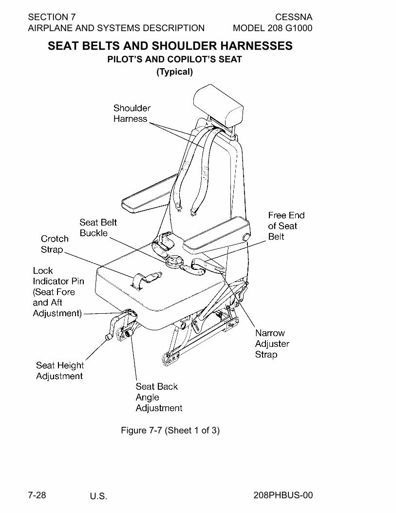
SECTION 7 CESSNAAIRPLANE AND SYSTEMS DESCRIPTION MODEL 208 G1000
U.S.7-28
SEAT BELTS AND SHOULDER HARNESSESPILOT’S AND COPILOT’S SEAT
(Typical)
Figure 7-7 (Sheet 1 of 3)
208PHBUS-00
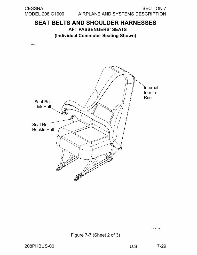
CESSNA SECTION 7MODEL 208 G1000 AIRPLANE AND SYSTEMS DESCRIPTION
U.S. 7-29
SEAT BELTS AND SHOULDER HARNESSESAFT PASSENGERS’ SEATS
(Individual Commuter Seating Shown)
Figure 7-7 (Sheet 2 of 3)
208PHBUS-00
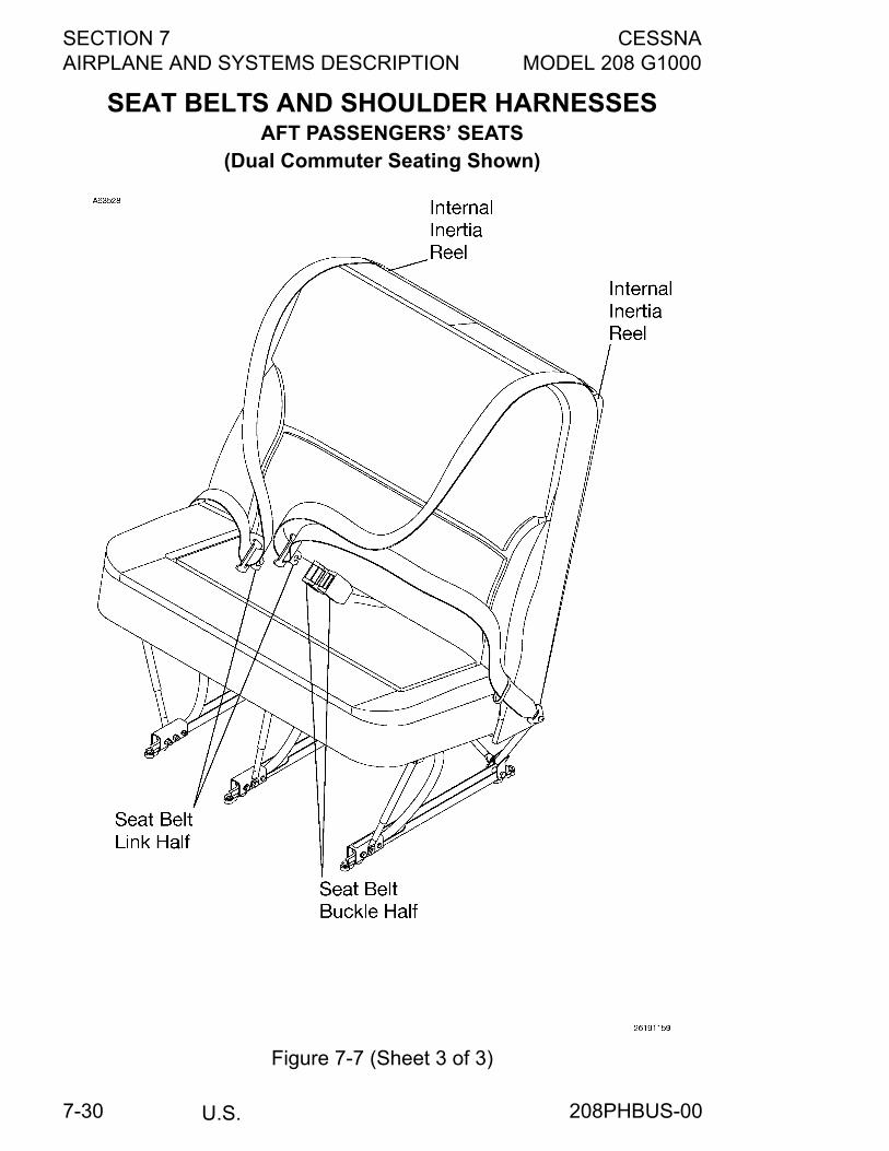
SECTION 7 CESSNAAIRPLANE AND SYSTEMS DESCRIPTION MODEL 208 G1000
U.S.7-30
SEAT BELTS AND SHOULDER HARNESSESAFT PASSENGERS’ SEATS
(Dual Commuter Seating Shown)
Figure 7-7 (Sheet 3 of 3)
208PHBUS-00
CESSNA SECTION 7MODEL 208 G1000 AIRPLANE AND SYSTEMS DESCRIPTION
U.S. 7-31
SEAT BELTS AND SHOULDER HARNESSESAll seat positions are equipped with seat belts and shoulder harnesses.The pilot’s and copilot’s seat positions are equipped with shoulderharnesses with inertia reels.
WARNING
Failure to correctly use seat belts and shoulderharnesses could result in serious or fatal injury inthe event of an accident.
SEAT BELTS, STRAP, AND SHOULDER HARNESSES(PILOT AND COPILOT SEATS)Both the pilot’s and copilot’s seat positions are equipped with a five-point restraint system which combines the function of conventional typeseat belts, a crotch strap, and an inertial reel equipped double-strapshoulder harness in a single assembly. The seat belts and crotch strapattach to fittings on the lower seat frame and the inertia reel for theshoulder harness attaches to the frame of the seat back.The right half of the seat belt contains the buckle, which is theconnection point for the left belt half, crotch strap, and shoulderharnesses. The left belt, crotch strap, and shoulder harnesses are fittedwith links which insert into the buckle. Both halves of the seat belt haveadjusters with narrow straps to enable the belt halves to be lengthenedprior to fastening.
(Continued Next Page)
208PHBUS-00
SECTION 7 CESSNAAIRPLANE AND SYSTEMS DESCRIPTION MODEL 208 G1000
U.S.7-32
SEAT BELTS, STRAP, AND SHOULDER HARNESSES(PILOT AND COPILOT SEATS) (Continued)
To use the restraint system, lengthen each half of the belt as necessaryby pulling the buckle (or connecting link) to the lap with one hand whilepulling outward on the narrow adjuster strap with the other hand. Insertthe left belt link into the left slot of the buckle. Bring the crotch strapupward and insert its link into the bottom slot in the buckle. Finally,position each strap of the shoulder harness over the shoulders andinsert their links into the upper slots in the buckle. the seat belts shouldbe tightened for a snug fit by grasping the free end of each belt andpulling up and inward.During flight operations, the inertia reel allows complete freedom ofupper body movement; however, in the event of a sudden deceleration,the reel will lock automatically to protect the occupant.
WARNING
Failure to correctly use seat belts and shoulderharnesses could result in serious or fatal injury inthe event of an accident.
Release of the belts, strap, and shoulder harnesses is accomplished bysimply twisting the front section of the buckle in either direction andpulling all connecting links free.
208PHBUS-00
CESSNA SECTION 7MODEL 208 G1000 AIRPLANE AND SYSTEMS DESCRIPTION
U.S. 7-33
CABIN ENTRY DOORSEntry to, and exit from the airplane is accomplished through a door oneach side of the cabin at the pilot’s and copilot’s positions and, on thePassenger Version only, through a two-piece, airstair-type door on theright side of the airplane aft of the wing (refer to Section 6 for cabin andcabin entry door dimensions). A cargo door on the left side of theairplane aft of the wing, also can be used for cabin entry.
CREW ENTRY DOORSThe left door for crew entry has a conventional exterior door handle, akey-operated door lock, a conventional interior door handle, a lockoverride knob, and an openable window. The right door for crew entryhas a conventional exterior door handle, a conventional interior doorhandle, and a manually-operated inside door lock. To open either entrydoor from outside the airplane (if unlocked), rotate the handle down andforward to the OPEN position. To close the door from inside theairplane, use the conventional door handle and door pull. The insidedoor handle is a three-position handle with OPEN, CLOSE andLATCHED positions. Place the handle in the CLOSE position and pullthe door shut; then rotate the handle forward to the LATCHED position.When the handle is rotated to the LATCHED position, an over-centeraction will hold it in that position.
CAUTION
Failure to correctly close and latch the left and rightcrew entry doors may cause the doors to open in flight.
A lock override knob on the inside of the left door for crew entryprovides a means of overriding the outside door lock from inside theairplane. To operate the override, pull the knob and rotate it in theplacarded direction to unlock or lock the door. Both crew doors shouldbe latched before flight, and should not be opened intentionally duringflight. To lock the doors for crew entry when leaving the airplane, lockthe right door with the manually-operated inside door lock, close the leftdoor, and, using the key, lock the door.
208PHBUS-00
SECTION 7 CESSNAAIRPLANE AND SYSTEMS DESCRIPTION MODEL 208 G1000
U.S.7-34
PASSENGER ENTRY DOOR (Passenger Version Only)The entry door for passengers consists of an upper and lower section.When opened, the upper section swings upward and the lower sectiondrops down providing integral steps to aid in boarding or exiting theairplane. The upper door section incorporates a conventional exteriordoor handle with a separate key-operated lock, a pushbutton exteriordoor release, and an interior door handle which snaps into a lockingreceptacle. The lower door section features a flush handle which isaccessible from either inside or outside the airplane. This handle isdesigned so that when the upper door is closed, the handle cannot berotated to the OPEN position. The lower door also contains integraldoor support cables and a door-lowering device. A cabin doorunlatched warning system is provided as a safety feature so that if theupper door is not properly latched, an Amber DOOR UNLATCHEDCAS MSG located on the PFD illuminates to alert the pilot.To enter the airplane through the passenger entry door, depress theexterior pushbutton door release, rotate the exterior door handle on theupper door section counterclockwise to the open position, and raise thedoor section to the overcenter position. Following this action, theautomatic door lift with the telescoping gas spring raises the door to thefull up position. When the upper section is open, release the lowersection by pulling up on the inside door handle and rotating the handleto the OPEN position. Lower the door section until it is supported by theintegral support cables. The door steps deploy automatically from theirstowed positions.
WARNING
The outside proximity of the lower door sectionmust be clear before opening the door.
(Continued Next Page)
208PHBUS-00
CESSNA SECTION 7MODEL 208 G1000 AIRPLANE AND SYSTEMS DESCRIPTION
U.S. 7-35
PASSENGER ENTRY DOOR (Passenger Version Only)(Continued)
To close the passenger entry door from the inside of the airplane, graspthe support cables of the lower door section and pull the door up untilthe top edge is within reach, then grasp the center of the door and pullinboard until the door is held snugly against the fuselage door frame.Rotate the inside handle forward to the CLOSE position and latch thelower door section. Check that the lower front and rear latches are correctly engaged. Afterthe lower door section is secured, grasp the pull strap on the upperdoor section and pull down and inboard. As the door nears the closedposition, pull inboard firmly to make sure the latching pawls engagecorrectly. When the latching pawls are engaged, rotate the insidehandle counterclockwise to the horizontal (latched) position, but do notuse excessive force. If the handle will not rotate easily, the door is notfully closed. Use a more firm closing motion to get the latching pawls toengage and rotate the door handle again to the latched position. Thensnap the interior handle into its locking receptacle.
CAUTION
Refer to Section 3, Emergency Procedures, for properoperational procedures to be followed if the passengerentry door should inadvertently open in flight.
To exit the airplane through the passenger entry door, pull the upperdoor section inside handle from its locked position receptacle, rotatingthe handle clockwise to the open position as you push the dooroutward. When the door is partially open, the automatic door lift willraise the upper door section to the fully open position. Next, rotate thedoor handle of the lower section up and aft to the open position andpush the door outward. The telescoping gas spring will lower the doorto its fully open position and the integral steps will deploy.
WARNING
The outside proximity of the lower door sectionmust be clear before opening the door.
(Continued Next Page)
208PHBUS-00
SECTION 7 CESSNAAIRPLANE AND SYSTEMS DESCRIPTION MODEL 208 G1000
U.S.7-36
PASSENGER ENTRY DOOR (Passenger Version Only)(Continued)
To close the passenger entry door from outside the airplane, raise thelower door section until the door is held firmly against the door frame inthe fuselage. Rotate the inside handle of the lower door section forwardand down to the CLOSE position. After the lower door section issecured, grasp the pull strap on the upper door section and pull down.As the door nears the closed position, grasp the edge of the door andpush inward firmly to make sure the latching pawls engage correctly.When engaged, rotate the outside door handle clockwise to thehorizontal (latched) position. After entering the airplane, snap theinterior handle of the upper door into its locking receptacle (unlesscargo obstructs access to the door). If desired when leaving theairplane parked, use the key in the outside key lock to lock the handlein the horizontal position.
WARNING
Do not use the outside key lock to lock the doorprior to flight. The door could not be opened fromthe inside if it were needed as an emergency exit.
CAUTION
Failure to properly latch the upper passenger doorsection will result in illumination of the Amber DOORWARNING CAS MSG. Inattention to this safety featuremay allow the upper cargo door to open in flight.
The exterior pushbutton-type lock release located on the upper doorsection just forward of the exterior door handle operates in conjunctionwith the interior door handle. It is used whenever it is desired to openthe door from outside the airplane while the interior door handle is inthe locked position. Depress the pushbutton to release the lock of theinterior door handle and to allow the exterior door handle to functionnormally to open the door.
208PHBUS-00
CESSNA SECTION 7MODEL 208 G1000 AIRPLANE AND SYSTEMS DESCRIPTION
U.S. 7-37
CARGO DOORSA two-piece cargo door is installed on the left side of the airplane justaft of the wing trailing edge. The cargo door is divided into an upperand a lower section. When opened, the upper section swings upwardand the lower section swings forward to create a large opening in theside of he fuselage which facilitates the loading of bulky cargo into thecabin. The upper section of the cargo door incorporates a conventionalexterior door handle with a separate key-operated lock, and, on thePassenger Version only, a pushbutton exterior emergency door releaseand an interior door handle which snaps into a locking receptacle. Theupper door also incorporates two telescoping door lifts which raise thedoor to the fully open position, when opened. A cargo door openwarning system is provided as a safety feature so that if the upper dooris not properly latched an Amber CAS MSG, labeled DOORUNLATCHED, located on the PFD, illuminates to alert the pilot. Thelower door section features a flush handle which is accessible fromeither inside or outside the airplane. The handle is designed so thatwhen the upper door is closed, the handle cannot be rotated to theopen position.
WARNING
In an emergency, do not attempt to exit the cargoversion through the cargo doors. Because theinside of the upper door has no handle, exit fromthe airplane through these doors without outsideassistance is not possible.
CAUTION
Failure to properly latch the upper cargo door sectionwill result in illumination of the Amber DOORWARNING CAS MSG. Inattention to this safety featuremay allow the upper cargo door to open in flight.
To open the cargo door from outside the airplane, depress the upperdoor section exterior pushbutton door release (Passenger Version only)and rotate the exterior door handle clockwise to the open position.Following this action, the telescoping door lifts will automatically raisethe door to the full up position. When the upper section is open, releasethe lower section by pulling up on the inside door handle and rotatingthe handle to the OPEN position. Open the door forward until it swingsaround next to the fuselage where it can be secured to the fuselage bya holding strap or chain.
(Continued Next Page)
208PHBUS-00
SECTION 7 CESSNAAIRPLANE AND SYSTEMS DESCRIPTION MODEL 208 G1000
U.S.7-38
CARGO DOORS (Continued)
To close the cargo door from outside the airplane, disconnect theholding strap or chain from the fuselage, swing the door aft to theclosed position, and hold the door firmly against the fuselage doorframe to assure engagement of the latching pawls. Rotate the insidehandle forward and down to the CLOSE position to latch the lower doorsection. After the lower door section is secured, grasp the pull strap onthe upper door section and pull down. As the door nears the closedposition, grasp the edge of the door and push inward firmly to assureengagement of the latching pawls. When engaged, the exterior doorhandle can be rotated counterclockwise to the horizontal (latched)position. On the Passenger Version only, after entering the airplane,snap the upper door interior handle into its locking receptacle (unlesscargo obstructs access to the door). If desired when leaving theairplane parked, use the key in the outside key lock to lock the handlein the horizontal position.To open the cargo door from inside the airplane (Passenger Versiononly), pull the inside door handle of the upper door section from itslocked position receptacle. Rotate the handle counterclockwise to thevertical position, and push the door outward. When the door is partiallyopen, the automatic door lifts will raise the upper door section to thefully open position. Next, rotate the door handle of the lower sectiondoor up and aft to the open position and push the aft end of the dooroutward. The door may be completely opened and secured to thefuselage with the holding strap or chain from outside.
WARNING
Do not attempt to exit the cargo version through thecargo doors. Because the inside of the upper doorhas no handle, exit from the airplane through thesedoors is not possible without outside assistance.
To close the cargo door from inside the airplane (Passenger Versiononly), disconnect the holding strap or chain from the fuselage andsecure it to the door. Pull the door aft to the closed position and hold theaft edge of the door firmly against the fuselage door frame to assureengagement of the latching pawls. Rotate the inside handle forwardand down to the CLOSE position to latch the lower door section (referto Section 2, Placards). After the lower door section is secured, graspthe pull strap on the upper door section and pull down. As the doornears the closed position, grasp the edge of the door and pull inwardfirmly to assure engagement of the latching pawls. When engaged, theinterior door handle can be rotated clockwise to the horizontal position.Snap the handle into its locking receptacle.
208PHBUS-00
CESSNA SECTION 7MODEL 208 G1000 AIRPLANE AND SYSTEMS DESCRIPTION
U.S. 7-39
CABIN WINDOWSThe airplane is equipped with a two-piece windshield reinforced with ametal center strip. The passenger version has sixteen cabin sidewindows of the fixed type including one each in the two crew entrydoors, two windows in the cargo door upper section, and one window inthe upper section of the passenger entry door. The pilot’s side windowincorporates a small triangular foul weather window. The foul weatherwindow may be opened for ground ventilation and additional viewing bytwisting the latch. The cargo version has only two cabin side windows,one in each crew entry door.
CONTROL LOCKSA control lock is provided to lock the aileron and elevator controlsurfaces to prevent damage to these systems by wind buffeting whilethe airplane is parked. The lock consists of a shaped steel rod and flag.The flag identifies it as a control lock and cautions about its removalbefore starting the engine. To install the control lock, align the hole inthe right side of the pilot’s control wheel shaft with the hole in the rightside of the shaft collar on the instrument panel and insert the rod intothe aligned holes. Installation of the lock will secure the ailerons in aneutral position and the elevators in a slightly trailing edge downposition. Proper installation of the lock will place the flag over the leftsidewall switch panel.The Ruder Gust Lock is a positive locking device consisting of abracket assembly and a bolt action lock attached to the rear bulkheadinside the tailcone stinger below the rudder. When engaged, the rudderis locked in the neutral position. A placard located below the lockhandle shaft on the left side of the tailcone explains the operation of therudder gust lock. The rudder gust lock is manually engaged anddisengaged on the ground by turning the airfoil-shaped handlemounted on the shaft projecting from the left side of the tailcone. Thelock is engaged by turning the handle downward so that its trailing edgepoints nearly due aft.
(Continued Next Page)
208PHBUS-00
SECTION 7 CESSNAAIRPLANE AND SYSTEMS DESCRIPTION MODEL 208 G1000
U.S.7-40
CONTROL LOCKS (Continued)
The Rudder Gust Lock has a fail-safe connection to the elevator controlsystem to ensure that it will always be disengaged before the airplanebecomes airborne. This fail-safe connection automatically disengagesthe lock when the elevator is deflected upward about one-fourth of itstravel from neutral. The pilot is responsible for disengaging the RudderGust Lock during the preflight inspection and operating the fail-safedisengagement mechanism by momentarily deflecting the elevator tothe full up position after the control lock is removed and before startingthe engine. If these procedures are not followed the rudder and rudderpedals will be locked in the neutral position making ground steeringimpossible. In the event that the engagement of the Rudder Gust Lockgoes completely unnoticed and the pilot commences a takeoff run withthe rudder system locked, the upward elevator deflection duringrotation will disengage the Rudder Gust Lock.Because of the fail-safe system, the elevator lock should always beengaged prior to engaging the Rudder Gust Lock when securing theairplane after shutdown.
NOTE
The control lock and any other type of locking device shouldbe removed or unlocked prior to starting the engine.
ENGINEThe Pratt & Whitney Canada Inc. PT6A-114A powerplant is a freeturbine engine. It utilizes two independent turbines; one driving acompressor in the gas generator section, and the second driving areduction gearing for the propeller.Inlet air enters the engine through an annular plenum chamber formedby the compressor inlet case where it is directed to the compressor.The compressor consists of three axial stages combined with a singlecentrifugal stage, assembled as an integral unit.A row of stator vanes located between each stage of compressor rotorblades diffuses the air, raises its static pressure and directs it to thenext stage of compressor rotor blades. The compressed air passesthrough diffuser ducts which turn it 90° in direction. It is then routedthrough straightening vanes into the combustion chamber.
(Continued Next Page)
208PHBUS-00
CESSNA SECTION 7MODEL 208 G1000 AIRPLANE AND SYSTEMS DESCRIPTION
U.S. 7-41
ENGINE (Continued)
The combustion chamber liner located in the gas generator caseconsists of an annular reverse-flow weldment provided with varyingsized perforations which allow entry of compressed air. The flow of airchanges direction to enter the combustion chamber liner where itreverses direction and mixes with fuel. The location of the combustionchamber liner eliminates the need for a long shaft between thecompressor and the compressor turbine, thus reducing the overalllength and weight of the engine.Fuel is injected into the combustion chamber liner by 14 simplexnozzles supplied by a dual manifold. the mixture is initially ignited bytwo spark igniters which protrude into the combustion chamber liner.The resultant gases expand from the combustion chamber liner,reverse direction and pass through the compressor turbine guide vaneto the compressor turbine. The turbine guide vanes ensure that theexpanding gases impinge on the turbine blades at the proper angle,with a minimum loss of energy. The still expanding gases pass forwardthrough a second set of stationary guide vanes to drive the powerturbine.The compressor and power turbines are located in the approximatecenter of the engine with their shafts extending in opposite directions.The exhaust gas from the power turbine is directed through an exhaustplenum to the atmosphere via a single exhaust port on the right side ofthe engine.The engine is flat rated at 675 shaft horsepower (1865 foot-poundstorque at 1900 RPM varying linearly to 1970 foot-pounds torque at1800 RPM). The speed of the gas generator (compressor) turbine (Ng)is 37,500 RPM at 100% Ng. Maximum permissible speed of the gasgenerator is 38,100 RPM which equals 101.6% Ng. The power turbinespeed is 33,000 RPM at a propeller shaft speed of 1900 RPM.All engine-driven accessories, with the exception of the propellertachometer-generator and the propeller governors, are mounted on theaccessory gearbox located at the rear of the engine. These are drivenby the compressor turbine with a coupling shaft which extends the drivethrough a conical tube in the oil tank center section.The engine oil supply is contained in an integral tank which forms partof the compressor inlet case. The tank has a drain and fill capacity of9.5 U.S. quarts and is provided with a dipstick and drain plug.The power turbine drives the propeller through a two-stage planetaryreduction gearbox located on the front of the engine. The gearboxembodies an integral torquemeter device which is instrumented toproved an accurate indication of the engine power output.
(Continued Next Page)
208PHBUS-00
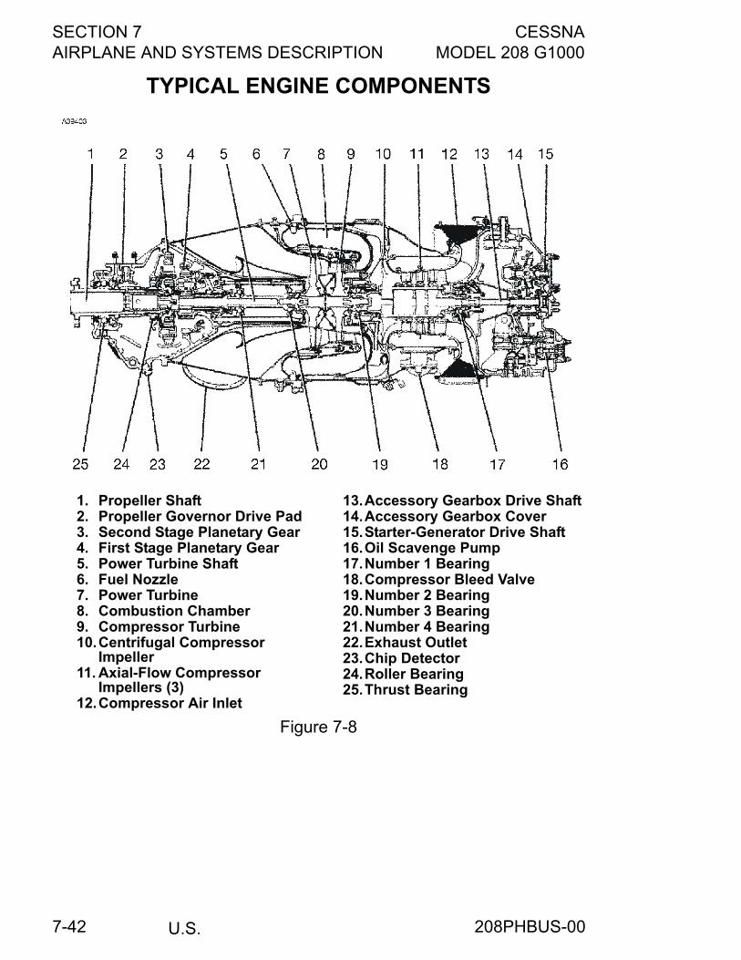
SECTION 7 CESSNAAIRPLANE AND SYSTEMS DESCRIPTION MODEL 208 G1000
U.S.7-42
TYPICAL ENGINE COMPONENTS
1. Propeller Shaft2. Propeller Governor Drive Pad3. Second Stage Planetary Gear4. First Stage Planetary Gear5. Power Turbine Shaft6. Fuel Nozzle7. Power Turbine8. Combustion Chamber9. Compressor Turbine10.Centrifugal Compressor
Impeller11. Axial-Flow Compressor
Impellers (3)12.Compressor Air Inlet
13.Accessory Gearbox Drive Shaft14.Accessory Gearbox Cover15.Starter-Generator Drive Shaft16.Oil Scavenge Pump17.Number 1 Bearing18.Compressor Bleed Valve19.Number 2 Bearing20.Number 3 Bearing21.Number 4 Bearing22.Exhaust Outlet23.Chip Detector24.Roller Bearing25.Thrust Bearing
Figure 7-8
208PHBUS-00
CESSNA SECTION 7MODEL 208 G1000 AIRPLANE AND SYSTEMS DESCRIPTION
U.S. 7-43
ENGINE CONTROLSThe engine is operated by four separate controls consisting of a powerlever, EMERGENCY POWER Lever, PROP RPM Lever, and a FUELCONDITION Lever. The power and FUEL CONDITION Levers areengine controls while the PROP RPM Lever controls propeller speedand feathering.
POWER LEVERThe power lever is connected through linkage to a cam assemblymounted in front of the fuel control unit at the rear of the engine. Thepower lever controls engine power through the full range frommaximum takeoff power back through idle to full reverse. The lever alsoselects propeller pitch when in the BETA range. The power lever hasMAX, IDLE, and BETA and REVERSE range positions. The range fromMAX position through IDLE enables the pilot to select the desiredpower output from the engine. The BETA range enables the pilot tocontrol propeller blade pitch from idle thrust back through a zero or no-thrust condition to maximum reverse thrust.
CAUTION
The propeller reversing linkage can be damaged if thepower lever is moved aft of the idle position when thepropeller is feathered.
208PHBUS-00
SECTION 7 CESSNAAIRPLANE AND SYSTEMS DESCRIPTION MODEL 208 G1000
U.S.7-44
EMERGENCY POWER LEVERThe EMERGENCY POWER Lever is connected through linkage to themanual override lever on the fuel control unit and governs fuel supply tothe engine should a pneumatic malfunction occur in the fuel controlunit. When the engine is operating, a failure of any pneumatic signalinput to the fuel control unit will result in the fuel flow decreasing tominimum idle (about 48% Ng at sea level and increasing with altitude).The EMERGENCY POWER Lever allows the pilot to restore power inthe event of such a failure. The EMERGENCY POWER Lever hasNORMAL, IDLE, and MAX positions. The NORMAL position is used forall normal engine operation when the fuel control unit is operatingnormally and engine power is selected by the power lever. The rangefrom IDLE position to MAX governs engine power and is used when apneumatic malfunction has occurred in the fuel control unit and thepower lever is ineffective. A mechanical stop in the lever slot requiresthat the EMERGENCY POWER Lever be moved to the left to clear thestop before it can be moved from the NORMAL (full aft) position to theIDLE position.
NOTE
The knob on the EMERGENCY POWER Lever hascrosshatching. The crosshatching is visible when the leveris in MAX position. Also, the EMERGENCY POWER Leveris annunciated by a Red CAS message on the PFDwhenever it is unstowed from the NORMAL position withthe ITT indications in either of the OFF or STRT modes.These precautions are intended to preclude starting of theengine with the EMERGENCY POWER Lever inadvertentlyplaced in any position other than NORMAL.
CAUTION
• The EMERGENCY POWER Lever and itsassociated manual override system are consideredto be an emergency system and should be used onlyin the event of a fuel control unit malfunction. Whenattempting a normal start, the pilot must ensure thatthe EMERGENCY POWER Lever is in the NORMAL(full aft) position; otherwise, an over-temperaturecondition may result.
• When using the fuel control manual override system,engine response may be more rapid than whenusing the power lever. Additional care is requiredduring engine acceleration to avoid exceedingengine limitations.
(Continued Next Page)
208PHBUS-01
CESSNA SECTION 7MODEL 208 G1000 AIRPLANE AND SYSTEMS DESCRIPTION
U.S. 7-45
EMERGENCY POWER LEVER (Continued)Operation of the EMERGENCY POWER Lever is prohibited with theprimary power lever out of the IDLE position. The EMERGENCYPOWER Lever overrides normal fuel control functions and results in thedirect operation of the fuel metering valve. The EMERGENCY POWERLever will override the automatic fuel governing and engineacceleration scheduling controlled during normal operation by theprimary power lever.
CAUTION
Inappropriate use of the EMERGENCY POWER Levermay adversely affect engine operation and durability.Use of the EMERGENCY POWER Lever during normaloperation of the power lever may result in enginesurges, or exceeding the ITT, NG, and torque limits.
PROPELLER CONTROL LEVERThe PROP RPM Lever is connected through linkage to the propellergovernor mounted on top of the front section of the engine, andcontrols propeller governor settings from the maximum RPM position tofull feather. The PROP RPM Lever has MAX, MIN, and FEATHERpositions. The MAX position is used when high RPM is desired andgoverns the propeller speed at 1900 RPM. PROP RPM Lever settingsfrom the MAX position to MIN permit the pilot to select the desiredengine RPM for cruise. The FEATHER position is used during normalengine shutdown to stop rotation of the power turbine and front sectionof the engine. Since lubrication is not available after the gas generatorsection of the engine has shut down, rotation of the forward section ofthe engine is not desirable. Also, feathering the propeller when theengine is shut down minimizes propeller windmilling during windyconditions. A mechanical stop in the lever slot requires that the PROPRPM Lever be moved to the left to clear the stop before it can bemoved into or out of the FEATHER position.
FUEL CONDITION LEVERThe FUEL CONDITION Lever is connected through linkage to acombined lever and stop mechanism on the fuel control unit. The leverand stop also function as an idle stop for the fuel control unit rod. TheFUEL CONDITION Lever controls the minimum RPM of the gasgenerator turbine (Ng) when the power lever is in the IDLE position.The FUEL CONDITION Lever has CUTOFF, LOW IDLE, and HIGHIDLE positions. The CUTOFF position shuts off all fuel to the enginefuel nozzles. LOW IDLE positions the control rod stop to provide anRPM of 52% Ng. HIGH IDLE positions the control rod stop to provide anRPM of 65% Ng.
208PHBUS-00
SECTION 7 CESSNAAIRPLANE AND SYSTEMS DESCRIPTION MODEL 208 G1000
U.S.7-46
QUADRANT FRICTION LOCKA quadrant friction lock, located on the right side of the pedestal, isprovided to minimize creeping of the engine controls once they havebeen set. The lock is a knurled knob which increases friction on theengine controls when rotated clockwise.
ENGINE INSTRUMENT SYSTEM (EIS)The G1000 Engine Indication System provides graphical indicators andnumeric values for engine, fuel, and electrical system parameters to thepilot. The EIS is shown in a vertical strip on the left side of the PFDduring engine starts and on the MFD during normal operation. If eitherthe MFD or PFD fails during flight, the EIS is shown on the remainingdisplay.The EIS consists of two pages that are selected using the ENGINEsoftkey. The ENGINE page provides indicators for Engine Torque,Engine ITT, Gas Generator RPM%, Propeller RPM, Oil Pressure, OilTemperature, Fuel Quantity, Fuel Flow, Battery Amps, Bus Voltage, andeither Anti-Ice Fluid Remaining or Propeller Amps. When the ENGINEsoftkey is pressed, the SYSTEM softkey will appear adjacent to theENGINE softkey. The SYSTEM page provides numerical values forparameters on the ENGINE page that are shown as indicators only.Torque, ITT, Ng% and Np RPM are displayed identically on theSYSTEM page. The SYSTEM page also provides numerical indicationfor fuel quantity, fuel totalizer (pounds remaining and pounds used),generator amps, standby alternator amps, battery amps, bus voltage,anti-ice remaining (gallons of fluid and hours remaining), and propelleramps.The engine and airframe unit provides data to the EIS, which displaysthe data for the ENGINE page described below. Engine operation ismonitored by: torque, ITT, Ng%, propeller RPM, oil pressure, oiltemperature, and fuel flow.
208PHBUS-00
CESSNA SECTION 7MODEL 208 G1000 AIRPLANE AND SYSTEMS DESCRIPTION
U.S. 7-47
TORQUE INDICATIONSTorque (TRQ) indication is displayed at the top of both the ENGINE andSYSTEM pages. The indicator is a round gage with a white pointer. Thetransmitter senses the difference between the engine torque pressureand the pressure in the engine case and transmits this data to theG1000. Normal operating range is indicated by a green arc thatextends from 0 to redline. Redline varies from 1865 to 1970 ft-lbsdepending on prop RPM.For normal cruise flight when prop RPM is between 1600-1900, a bluetorque “bug” is included on the arc. This indicates maximum allowedcruise torque per the cruise performance and maximum torque chartsin section 5, Performance. The blue advisory cruise torque bug locatedon the EIS torque indication is not to be used as the primary means ofsetting cruise torque. Always refer to the appropriate performance chartin Section 5 of the POH/AFM.
PROPELLER RPM INDICATIONSThe propeller RPM (PROP RPM) is indicated numerically below GasGenerator RPM. The digits are white with RPM between 0-1599 RPM,green between 1600-1900 RPM, and white with a red backgroundwhen RPM is greater than or equal to 1910. The instrument iselectrically operated from the propeller tachometer-generator which ismounted on the right side of the front case.
ITT INDICATIONInterstage Turbine Temperature (ITT) is indicated below torque and isround dial gage with a white pointer. This instrument displays gastemperature between the compressor and power turbines. With theengine off or during start ITT indicator displays a green band from100°C to 740°C, an Amber caution band from 766°C-805°C and aredline at 1090°C. The gage is graduated at 100 degree intervals from600°C to 1100°C.With the engine running a green arc indicates normal operating rangefrom 100°C to 740°C, an Amber caution region from 765°C-805°C witha redline at 805°C. The gage is graduated at 50 degree intervals from600°C-900°C. The digital readout flashes red when an over-temperature situation has occurred.
GAS GENERATOR RPM INDICATIONSGas generator RPM (Ng) is displayed below ITT using a round dialgage with a white pointer. RPM is displayed as a percentage ofmaximum gas generator RPM. The instrument is electrically operatedfrom the gas generator tachometer-generator mounted on the lowerright portion of the accessory case. The gage has tick marks at 0, 12,50, and 105% with a redline at 101.6%.
208PHBUS-00
SECTION 7 CESSNAAIRPLANE AND SYSTEMS DESCRIPTION MODEL 208 G1000
U.S.7-48
FUEL FLOW INDICATIONSDetails of the fuel flow indicator are included under Fuel System in alater paragraph in this section.
OIL PRESSURE INDICATIONOil Pressure (OIL PSI) is displayed using a varied color tape and 3 digitdisplay on the ENGINE page. Oil pressure is indicated using atransducer that senses oil pressure from the accessory case andtransmits the information to the G1000. Normal operation is indicatedfrom 85 to 105 psi; caution region is indicated by an amber bar from 40psi to less than 85 psi. Warning region is indicated by red lines and redflashing digits at less than 40 psi and greater that 105 psi
OIL TEMPERATURE INDICATION
Oil temperature (OIL °C) is displayed using a varied color tape anddigital display; the display can be 3 digits on the ENGINE page. Theinstrument is operated by an electrical-resistance type temperaturesensor. Normal operation is indicated between 10 and 99°C; AMBERcaution regions are indicated from -40 to less than 10°C and from 100to 104°C. Red lines are included at -41 and 105°C. Digits vary in colorbetween green, amber or red in correlation with the pointer and tape.
NEW ENGINE BREAK-IN AND OPERATIONThere are no specific break-in procedures required for the Pratt &Whitney Canada Inc. PT6A-114A turboprop engine. The engine may besafely operated throughout the normal ranges authorized by themanufacturer at the time of delivery of your airplane.
208PHBUS-00
CESSNA SECTION 7MODEL 208 G1000 AIRPLANE AND SYSTEMS DESCRIPTION
U.S. 7-49
ENGINE LUBRICATION SYSTEMThe lubrication system consists of a pressure system, a scavengesystem and a breather system. The main components of the lubricationsystem include an integral oil tank at the back of the engine, an oilpressure pump at the bottom of the oil tank, an external double-elementscavenge pump located on the back of the accessory case, an internaldouble-element scavenge pump located inside the accessory gearbox,an oil-to-fuel heater located on the top rear of the accessory case, anoil filter located internally on the right side of the oil tank, and an oilcooler located on the right side of the nose cowl.Oil is drawn from the bottom of the oil tank through a filter screen whereit passes through a pressure relief valve for regulation of oil pressure.The pressure oil is then delivered from the main oil pump to the oil filterwhere extraneous matter is removed from the oil and precluded fromfurther circulation. Pressure oil is then routed through passageways tothe engine bearings, reduction gears, accessory drives, torquemeter,and propeller governor. Also, pressure oil is routed to the oil-to-fuelheater where it then returns to the oil tankAfter cooling and lubricating the engine moving parts, oil is scavengedas follows:
1. Oil from the number 1 bearing compartment is returned by gravityinto the accessory gearbox.
2. Oil from the number 2 bearing is scavenged by the front elementof the internal scavenge pump back into the accessory gearbox.
3. Oil from the number 3 and number 4 bearings is scavenged bythe front element of the external scavenge pump into theaccessory gearbox.
4. Oil from the propeller governor, front thrust bearing, reductiongear accessory drives, and torquemeter is scavenged by the rearelement of the external scavenge pump where it is routed througha thermostatically-controlled oil cooler and then returned to the oiltank.
5. The rear element of the internal scavenge pump scavenges oilfrom the accessory case and routes it through the oil coolerwhere it then returns to the oil tank.
(Continued Next Page)
208PHBUS-00
SECTION 7 CESSNAAIRPLANE AND SYSTEMS DESCRIPTION MODEL 208 G1000
U.S.7-50
ENGINE LUBRICATION SYSTEM (Continued)
Breather air from the engine bearing compartments and from theaccessory and reduction gearboxes is vented overboard through acentrifugal breather installed in the accessory gearbox. The bearingcompartments are connected to the accessory gearbox by coredpassages and existing scavenge oil return lines. A bypass valve,immediately upstream of the front element of the internal scavengepump, vents the accessory gearbox when the engine is operating athigh power.An oil dipstick/filler cap is located at the rear of the engine on the leftside and is accessible when the left side of the upper cowling is raised.Markings which indicate U.S. quarts low if the oil is hot are provided onthe dipstick to facilitate oil servicing. The oil tank capacity is 9.5 U.S.quarts and total system capacity is 14 U.S. quarts. For engine oil typeand brand, refer to Section 8.
IGNITION SYSTEMThe ignition system consists of two igniters, an ignition exciter, twohigh-tension leads, an ignition monitor light, an ignition switch, and astarter switch. Engine ignition is provided by two igniters in the enginecombustion chamber. The igniters are energized by the ignition excitermounted on the engine mount on the right side of the enginecompartment. Electrical energy from the ignition exciter is transmittedthrough two high-tension leads to the igniters in the engine. The ignitionsystem is normally energized only during engine start.Ignition is controlled by an ignition switch and a starter switch locatedon the left sidewall switch and circuit breaker panel. The ignition switchhas two positions, ON and NORMAL. The NORMAL position of theswitch arms the ignition system so that ignition will be obtained whenthe starter switch is placed in the START position. The NORMALposition is used during all ground starts and during air starts with starterassist. The ON position of the switch provides continuous ignitionregardless of the position of the starter switch. This position is used forair starts without starter assist, for operation on water-covered runways,during flight in heavy precipitation, during inadvertent icing encountersuntil the inertial separator has been in bypass for 5 minutes, and whennear fuel exhaustion as indicated by illumination of the Red RSVRFUEL LOW CAS MSG.
(Continued Next Page)
208PHBUS-00
CESSNA SECTION 7MODEL 208 G1000 AIRPLANE AND SYSTEMS DESCRIPTION
U.S. 7-51
IGNITION SYSTEM (Continued)
The main function of the starter switch is control of the starter forrotating the gas generator portion of the engine during starting.However, it also provides ignition during starting. For purposes of thisdiscussion, only the ignition functions of the switch are described. Forother functions of the starter switch, refer to paragraph titled StartingSystem, in this section. The starter switch has three positions, OFF,START, and MOTOR. The OFF position shuts off the ignition systemand is the normal position at all times except during engine start orengine clearing. The START position energizes the engine ignitionsystem provided the ignition switch is in the NORMAL position. Afterthe engine has started during a ground or air start, the starter switchmust be manually positioned to OFF for generator operation.White IGNITION ON CAS MSG will illuminate when electrical power isbeing applied to the igniters. The ignition system is protected by a pull-off type circuit breaker, labeled IGN, on the left sidewall switch andcircuit breaker panel.
AIR INDUCTION SYSTEMThe engine air inlet is located at the front of the engine nacelle to theleft of the propeller spinner. Ram air entering the inlet flows throughducts and an inertial separator system and then enters the enginethrough a circular plenum chamber where it is directed to thecompressor by guide vanes. The compressor air inlet incorporates ascreen which will prevent entry of large articles, but does not filter theinlet air.
208PHBUS-00
SECTION 7 CESSNAAIRPLANE AND SYSTEMS DESCRIPTION MODEL 208 G1000
U.S.7-52
INERTIAL SEPARATOR SYSTEMAn inertial separator system in the engine air inlet duct preventsmoisture particles from entering the compressor air inlet plenum whenin bypass mode. The inertial separator consists of two movable vanesand a fixed airfoil which, during normal operation, route the inlet airthrough a gentle turn into the compressor air inlet plenum. Whenseparation of moisture particles is desired, the vanes are positioned sothat the inlet air is forced to execute a sharp turn in order to enter theinlet plenum. This sharp turn causes any moisture particles to separatefrom the inlet air and discharge overboard through the inertial separatoroutlet in the left side of the cowling.Inertial separator operation is controlled by a T-handle located on thelower instrument panel. The T-handle is labeled BYPASS-PULL,NORMAL-PUSH. The inertial separator control should be moved to theBYPASS position prior to running the engine during ground or flightoperation in visible moisture (clouds, rain, snow, ice crystals) with anOAT of 5°C (41°F) or less. It may also be used for ground operations ortakeoffs from dusty, sandy field conditions to minimize ingestion offoreign particles into the compressor. The NORMAL position is used forall other operations.The T-handle locks in the NORMAL position by rotating the handleclockwise 1/4 turn to its vertical position. To unlock, push forwardslightly and rotate the handle 90° counterclockwise. The handle canthen be pulled into the BYPASS position. Once moved to the BYPASSposition, air loads on the movable vanes hold them in this position.
CAUTION
Do not return the INERTIAL SEPARATOR to NORMALuntil after engine shutdown and inspection if icingconditions are encountered.
NOTE
When moving the inertial separator control from BYPASS toNORMAL position during flight, reduction of engine powerwill reduce the control forces.
(Continued Next Page)
208PHBUS-00
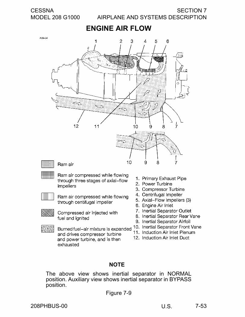
CESSNA SECTION 7MODEL 208 G1000 AIRPLANE AND SYSTEMS DESCRIPTION
U.S. 7-53
ENGINE AIR FLOW
NOTE
The above view shows inertial separator in NORMALposition. Auxiliary view shows inertial separator in BYPASSposition.
Figure 7-9
208PHBUS-00
SECTION 7 CESSNAAIRPLANE AND SYSTEMS DESCRIPTION MODEL 208 G1000
U.S.7-54
EXHAUST SYSTEMThe exhaust system consists of a primary exhaust pipe attached to theright side of the engine just aft of the propeller reduction gearbox. Asecondary exhaust duct, fitted over the end of the primary exhaust pipecarries the exhaust gases away from the cowling and into theslipstream. The juncture of the primary exhaust pipe and secondaryexhaust duct is located directly behind the oil cooler. Since thesecondary exhaust duct is of larger diameter than the primary exhaustpipe, a venturi effect is produced by the flow of exhaust. This venturieffect creates a suction behind the oil cooler which augments the flowof cooling air through the cooler. This additional airflow improves oilcooling during ground operation of the engine.
ENGINE FUEL SYSTEMThe engine fuel system consists of an oil-to-fuel heater, an engine-driven fuel pump, a fuel control unit, a flow divider and dump valve, adual fuel manifold with 14 simplex nozzles, and two fuel drain lines. Thesystem provides fuel flow to satisfy the speed and power demands ofthe engine.Fuel from the airplane reservoir is supplied to the oil-to-fuel heaterwhich utilizes heat from the engine lubricating oil system to preheat thefuel in the fuel system. A fuel temperature-sensing oil bypass valveregulates the fuel temperature by either allowing oil to flow through theheater circuit or bypass it to the engine oil tank.Fuel from the oil-to-fuel heater then enters the engine-driven fuel pumpchamber through a 74-micron inlet screen. The inlet screen is spring-loaded and should it become blocked, the increase in differentialpressure will overcome the spring and allow unfiltered fuel to flow intothe pump chamber. The pump increases the fuel pressure and deliversit to the fuel control unit via a 10-micron filter in the pump outlet. Abypass valve and cored passages in the pump body enables unfilteredhigh pressure fuel to flow to the fuel control unit in the event the outletfilter becomes blocked.
(Continued Next Page)
208PHBUS-00
CESSNA SECTION 7MODEL 208 G1000 AIRPLANE AND SYSTEMS DESCRIPTION
U.S. 7-55
ENGINE FUEL SYSTEM (Continued)
The fuel control unit consists of a fuel metering section, a temperaturecompensating section, and a gas generator (Ng) pneumatic governor.The fuel control unit determines the proper fuel schedule to provide thepower required as established by the power lever input. This isaccomplished by controlling the speed of the compressor turbine. Thetemperature compensating section alters the acceleration fuel scheduleto compensate for fuel density differences at different fueltemperatures, especially during engine start. The power turbinegovernor, located in the propeller governor housing, provides powerturbine overspeed protection in the event of propeller governor failure.This is accomplished by limiting fuel to the gas generator. Duringreverse thrust operation, maximum power turbine speed is controlledby the power turbine governor. The temperature compensator alters theacceleration fuel schedule of the fuel control unit to compensate forvariations in compressor inlet air temperature. Engine characteristicsvary with changes in inlet air temperature, and the acceleration fuelschedule must, in turn, be altered to prevent compressor stall and/orexcessive turbine temperatures.The flow divider schedules the metered fuel, from the fuel control unit,between the primary and secondary fuel manifolds. The fuel manifoldand nozzle assemblies supply fuel to the combustion chamber through10 primary and 4 secondary fuel nozzles, with the secondary nozzlescutting in above a preset value. All nozzles are operative at idle andabove.When the fuel cutoff valve in the fuel control unit closes during engineshutdown, both primary and secondary manifolds are connected to adump valve port and residual fuel in the manifolds is allowed to draininto the fuel can attached to the firewall where it can be drained daily.
COOLING SYSTEMNo external cooling provisions are provided for the PT6A-114A enginein this installation. however, the engine incorporates an extensiveinternal air system which provides for bearing compartment sealing andfor compressor and power turbine disk cooling. For additionalinformation on internal engine air systems, refer to the enginemaintenance manual for the airplane.
208PHBUS-00
SECTION 7 CESSNAAIRPLANE AND SYSTEMS DESCRIPTION MODEL 208 G1000
U.S.7-56
STARTING SYSTEMThe starting system consists of a starter-generator, a starter switch,and an Amber STARTER ON CAS MSG. The starter-generatorfunctions as a motor for engine starting and will motor the gasgenerator section until a speed of 46% Ng is reached, at which time, thestart cycle will automatically be terminated by a speed sensing switchlocated in the starter-generator. The starter-generator is controlled by athree-positioned starter switch located on the left sidewall switch andcircuit breaker panel. The switch has OFF, START, and MOTORpositions. The OFF position deenergizes the ignition and starter circuitsand is the normal position at all times except during engine start. TheSTART position of the switch energizes the starter-generator whichrotates the gas generator portion of the engine for starting. Also, theSTART position energizes the ignition system, provided the ignitionswitch is in the NORMAL position. When the engine has started, thestarter switch must be manually placed in the OFF position to de-energize the ignition system and activate the generator system. TheMOTOR position of the switch motors the engine without having theignition circuit energized and is used for motoring the engine when anengine start is not desired. This can be used for clearing fuel from theengine, washing the engine compressor, etc. The MOTOR position isspring-loaded to the OFF position. Also, an interlock between theMOTOR position of the starter switch and the ignition switch preventsthe starter from motoring unless the ignition switch is in the NORMALposition. This prevents unintentional motoring of the engine with theignition on. Starter contactor operation is indicated by an AmberSTARTER ON CAS MSG.
ENGINE ACCESSORIESAll engine-driven accessories, with the exception of the propellertachometer-generator and the propeller governors, are mounted on theaccessory gearbox. located at the rear of the engine. Theseaccessories are driven from the compressor turbine by a coupling shaftwhich extends the drive through a conical tube in the oil tank centersection.
208PHBUS-00
CESSNA SECTION 7MODEL 208 G1000 AIRPLANE AND SYSTEMS DESCRIPTION
U.S. 7-57
OIL PUMPPressure oil is circulated from the integral oil tank through the enginelubrication system by a self-contained, gear-type pressure pumplocated in the lowest part of the oil tank. The oil pump is contained in acast housing which is bolted to the front face of the accessorydiaphram, and is driven by the accessory gear shaft. The oil pump bodyincorporates a circular mounting boss to accommodate a check valve,located in the end of the filter housing. A second mounting boss on thepump accommodates a pressure relief valve.
FUEL PUMPThe engine-driven pump is mounted on the accessory gearbox at the 2o’clock position. The pump is driven through a gear shaft and splinedcoupling. The coupling splines are lubricated by oil mist from theauxiliary gearbox through a hole in the gear shaft. Another splinedcoupling shaft extends the drive to the fuel control unit which is boltedto the rear face of the pump. Fuel from the oil-to-fuel heater enters thefuel pump through a 74-micron inlet screen. Then, fuel enters the pumpgear chamber, is boosted to high pressure, and delivered to the fuelcontrol unit through a 10-micron pump outlet filter. A bypass valve andcored passages in the pump casing enable unfiltered high pressure fuelto flow from the pump gears to the fuel control unit should the outletfilter become blocked. An internal passage originating at the matingface with the fuel control unit returns bypass fuel from the fuel controlunit to the pump inlet downstream of the inlet screen. A pressureregulating valve in this line serves to pressurize the pump gearbushings.
Ng TACHOMETER-GENERATORThe Ng tachometer-generator produces an electric current which isused in conjunction with the gas generator% RPM indicator to indicategas generator RPM. The Ng tachometer-generator drive and mountpad is located at the 5 o’clock position on the accessory gearbox and isdriven from the internal scavenger pump.
208PHBUS-00

SECTION 7 CESSNAAIRPLANE AND SYSTEMS DESCRIPTION MODEL 208 G1000
U.S.7-58
PROPELLER TACHOMETER-GENERATORThe propeller tachometer-generator produces an electric signal whichis used in conjunction with the propeller RPM indicator. The propellertachometer- generator drive and mount pad is located on the right sideof the reduction gearbox case and rotates clockwise with a drive ratio of0.1273:1.
TORQUEMETERThe torquemeter is a hydro-mechanical torque measuring devicelocated inside the first stage reduction gear housing to provide anaccurate indication of engine power output. The difference between thetorquemeter pressure and the reduction gearbox internal pressureaccurately indicates the torque being produced. The two pressures areinternally routed to bosses located on the top of the reduction gearboxfront case and to a pressure transducer which is electrically connectedto the G1000 which indicates the correct torque. For standby indication,the pressures are routed to bosses on the top of the reductiongearcase front case and plumbed to the standby torque indicator.
STARTER-GENERATORThe starter-generator is mounted on the top of the accessory case atthe rear of the engine. The starter-generator is a 28-volt, 200-ampengine-driven unit that functions as a motor for engine starting and,after engine start, as a generator for the airplane electrical system.When operating as a starter, a speed sensing switch in the starter-generator will automatically shut down the starter, thereby providingoverspeed protection and automatic shutoff. The starter-generator is aircooled by an integral fan and by ram air ducted from the front of theengine cowling.
INTERSTAGE TURBINE TEMPERATURE SENSINGSYSTEMThe interturbine temperature sensing system is designed to provide theoperator with an accurate indication of engine operating temperaturestaken between the compressor and power turbines. The systemconsists of twin leads, two bus bars, and eight individual chromel-alumel thermocouple probes connected in parallel. Each probeprotrudes through a threaded boss on the power turbine stator housinginto an area adjacent to the leading edge of the power turbine vanes.The probe is secured to the boss by means of a floating, threadedfitting which is part of the thermocouple probe assembly. Shieldedleads connect each bus bar assembly to a terminal block whichprovides a connecting point for external leads to the ITT indicator in theairplane cabin.
208PHBUS-00
CESSNA SECTION 7MODEL 208 G1000 AIRPLANE AND SYSTEMS DESCRIPTION
U.S. 7-59
PROPELLER GOVERNORThe propeller governor is located in the 12 o’clock position on the frontcase of the reduction gearbox. Under normal conditions, the governoracts as a constant speed unit, maintaining the propeller speed selectedby the pilot by varying the propeller blade pitch to match the load to theengine torque. The propeller governor also has a power turbinegovernor section built into the unit. Its function is to protect the engineagainst a possible power turbine overspeed in the event of a propellergovernor failure. If such an overspeed should occur, a governing orificein the propeller governor is opened by flyweight action to bleed offcompressor discharge pressure through the governor and computingsection of the fuel control unit. When this occurs, compressor dischargepressure, acting on the fuel control unit governor bellows, decreasesand moves the metering valve in a closing direction, thus reducing fuelflow to the flow divider.
PROPELLER OVERSPEED GOVERNORThis propeller overspeed governor is located at the 10 o’clock positionon the front case of the reduction gearbox. The governor acts as asafeguard against propeller overspeed should the primary propellergovernor fail. The propeller overspeed governor regulates the flow of oilto the propeller pitch-change mechanism by means of a flyweight andspeeder spring arrangement similar to the primary propeller governor.Because it has no mechanical controls, the overspeed governor isequipped with a test solenoid that resets the governor below its normaloverspeed setting for ground test. The OVERSPEED GOVERNORPUSH TO TEST Switch is located on the left side of the instrumentpanel. For a discussion of this switch, refer to the paragraph titledPropellers in this section.
208PHBUS-02
SECTION 7 CESSNAAIRPLANE AND SYSTEMS DESCRIPTION MODEL 208 G1000
U.S.7-60
ENGINE FIRE DETECTION SYSTEMThe engine fire detection system consists of a heat sensor in theengine compartment, a Red ENGINE FIRE CAS MSG located on thePFD, and a warning horn above the pilot. The heat sensor consists ofthree flexible closed loops. When high engine compartmenttemperatures are experienced, the heat causes a change in resistancein the closed loops. This change in resistance is sensed by a controlbox, located on the aft side of the firewall, which will illuminate the RedENGINE FIRE CAS MSG and trigger the audible warning horn. Firewarning is initiated when temperatures in the engine compartmentexceed 425ºF (218ºC) on the first section (firewall), 625ºF (329ºC) onthe second section (around the exhaust), or 450ºF (232ºC) on the thirdsection (rear engine compartment).A test switch, labeled TEST SWITCH, FIRE DETECT - UP, is locatedon the lower left corner of the instrument panel. When this switch isplaced in the UP position, the Red ENGINE FIRE CAS MSG willilluminate on the CAS system and the warning horn will soundindicating that the fire warning circuitry is operational. The system isprotected by a pull-off type circuit breaker, labeled FIRE DET, on the leftsidewall switch and circuit breaker panel.
ENGINE GEAR REDUCTION SYSTEMThe reduction gear and propeller shaft, located in the front of theengine, are housed in two magnesium alloy castings which are boltedtogether at the exhaust outlet. The gearbox contains a two-stageplanetary gear train, three accessory drives, and propeller shaft. Thefirst-stage reduction gear is contained in the rear case, while thesecond-stage reduction gear, accessory drives, and propeller shaft arecontained in the front case. Torque from the power turbine istransmitted to the first-stage reduction gear, from there to the second-stage reduction gear, and then to the propeller shaft. The reductionratio is from a maximum power turbine speed of 33,000 RPM down to apropeller speed of 1900 RPM.The accessories, located on the front case of the reduction gearbox,are driven by a bevel gear mounted at the rear of the propeller shaftthrust bearing assembly. Drive shafts from the bevel drive gear transmitrotational power to the three pads which are located at the 12, 3 and 9o'clock positions. Propeller thrust loads are absorbed by a flanged ballbearing assembly located on the front face of the reduction gearboxcenter bore. The bevel drive gear adjusting spacer, thrust bearing, andseal runner are stacked and secured to the propeller shaft by a key-washer and spanner nut. A thrust bearing cover assembly is securedby bolts at the front flange of the reduction gearbox front case.
208PHBUS-02
CESSNA SECTION 7MODEL 208 G1000 AIRPLANE AND SYSTEMS DESCRIPTION
U.S. 7-61
CHIP DETECTORSTwo chip detectors are installed on the engine, one on the underside ofthe reduction gearbox case and one on the underside of the accessorygearbox case. The chip detectors trigger an Amber CHIP DETECTCAS MSG on the instrument panel. The CAS message will illuminatewhen metal chips are present in one or both of the chip detectors.Illumination of the Amber CHIP DETECT CAS MSG necessitates theneed for inspection of the engine for abnormal wear.
OIL BREATHER DRAIN CANModel 208 airplanes have an oil breather drain can mounted on theright lower engine mount truss. This can collects any engine oildischarge coming from the accessory pads for the alternator drivepulley, starter/generator, air conditioner compressor (if installed), andthe propeller shaft seal. This can should be drained after every flight. Adrain valve on the bottom right side of the engine cowling enables thepilot to drain the contents of the oil breather drain can into a suitablecontainer. The allowable quantity of oil discharge per hour of engineoperation is 14 cc for airplanes with air conditioning and 11 cc forairplanes without air conditioning. If the quantity of oil drained from thecan is greater than specified, the source of the leakage should beidentified and corrected prior to further flight.
PROPELLERThe airplane is equipped standard with a McCauley aluminum material,three-bladed propeller or an optional Hartzell composite material, threebladed propeller. The propeller is constant-speed, full-feathering,reversible, single-acting, governor-regulated propeller. A settingintroduced into the governor with the PROP RPM Lever establishes thepropeller speed. The propeller utilizes oil pressure which opposes theforce of springs and counter-weights to obtain correct pitch for theengine load. Oil pressure from the propeller governor drives the bladestoward low pitch (increases RPM) while the springs and counterweightsdrive the blades toward high pitch (decreasing RPM). The source of oilpressure for propeller operation is furnished by the engine oil system,boosted in pressure by the governor gear pump, and supplied to thepropeller hub through the propeller flange.
(Continued Next Page)
208PHBUS-02
SECTION 7 CESSNAAIRPLANE AND SYSTEMS DESCRIPTION MODEL 208 G1000
U.S.7-62
PROPELLER (continued)
To feather the propeller blades, the PROP RPM Lever on the controlpedestal is placed in the FEATHER position; counterweights and springtension will continue to twist the propeller blades through high pitch andinto the streamlined or feathered position. Unfeathering the propeller isaccomplished by positioning the PROP RPM Lever forward of thefeather gate. The unfeathering system uses engine oil pressure to forcethe propeller out of feather.Reversed propeller pitch is available for decreasing ground roll duringlanding. To accomplish reverse pitch, the power lever is retardedbeyond IDLE and well into the BETA range. Maximum reverse power isaccomplished by retarding the power lever to the MAX REVERSEposition which increases power output from the gas generator andpositions the propeller blades at full reverse pitch. An externallygrooved feedback ring is provided with the propeller.Motion of the feedback ring is proportional to propeller blade angle, andis picked up by a carbon block running in the feedback ring. Therelationship between the axial position of the feedback ring and thepropeller blade angle is used to maintain control of blade angle fromidle to full reverse.
CAUTION
The propeller reversing linkage can be damaged if thepower lever is moved aft of the idle position when thepropeller is feathered.
PROPELLER ANTI-ICE BOOTS
The propeller anti-ice system provides protection for the propeller bladesurfaces when inadvertent icing conditions are encountered. Thesystem is operated by a three-position toggle switch labeled PROPHEAT on the anti-ice switch panel. When the switch is placed in theAUTO (upper) position, electric current flows to an anti-ice timer, whichcycles the current simultaneously to the heating elements in the anti-iceboots on the three propeller blades in intervals of 90 seconds ON and90 seconds OFF. The anti-ice timer will reset when the anti-ice switch isplaced in the OFF position.
(Continued Next Page)
208PHBUS-02
CESSNA SECTION 7MODEL 208 G1000 AIRPLANE AND SYSTEMS DESCRIPTION
U.S. 7-63
PROPELLER ANTI-ICE BOOTS (continued)
This 90-second cycle allows ice to build up on the propeller boots, thensheds it during the ON cycle. Due to the propeller blade ice sheddingcharacteristics, a slight propeller vibration occurring at the start of thepropeller anti-ice ON cycle and lasting 20-30 seconds is considerednormal. However, if the vibration continues longer than 30 seconds, oris perceived by the pilot as being excessive, exercising the propellercontrol lever and returning it to the MAX position will shed theremaining ice on the blades. If the vibration continues, refer to thePropeller Anti-Ice System Malfunction checklist in Section 3.
NOTE
An oil-operated pressure switch installed in the electricalcircuit is utilized to prevent the propeller anti-ice systemfrom being turned on without the engine running. A failureof this switch during normal Propeller Heat operation will beannunciated by an Amber PROP DE-ICE CAS message.
The switch is off when placed in the middle position. In the event of amalfunction in the anti-ice timer, the switch can be held for 90 secondsin the MANUAL (lower) position to achieve emergency propelleranti-icing. When operating in the MANUAL switch position, it isimportant to cycle the switch in intervals of 90 seconds MANUAL (ON)and 90 seconds OFF, the same cycling that occurs when the switch isin the AUTO position.
WARNING
If the PROP HEAT Switch is held in the MANUALposition without being cycled every 90 seconds, iceon the boots melts and runs back past the bootsand refreezes. This build up of runback ice maycause a loss in propeller efficiency which reducesairplane performance.
Operation of the propeller anti-ice system can be checked bymonitoring the PROP AMPS display below BUS VOLTS on theEIS-ENGINE display. The system is protected by two pull-off typecircuit breakers, a control PROP ANTI-ICE CONT circuit breaker and aPROP ANTI-ICE circuit breaker. Both circuit breakers are located onthe left sidewall circuit-breaker panel.
208PHBUS-02
SECTION 7 CESSNAAIRPLANE AND SYSTEMS DESCRIPTION MODEL 208 G1000
U.S.7-64
OVERSPEED GOVERNOR TEST SWITCHAn overspeed governor test switch is located on the left side of theinstrument panel. The switch is the push-to-test type and is used to testthe propeller overspeed governor during engine run-up. The switch,when depressed, actuates a solenoid on the propeller overspeedgovernor which restricts propeller RPM when the power lever isadvanced. To check for proper operation of the overspeed governor,during engine run-up, depress the press-to-test switch and advance thepower lever until propeller RPM stabilizes; propeller RPM should notexceed 1750 +/- 60 RPM.
FUEL SYSTEMThe airplane fuel system (see Fuel System figure) consists of twovented, integral fuel tanks with shutoff valves, a fuel selectors offwarning system, a fuel reservoir, an ejector fuel pump, an electricauxiliary boost pump, a reservoir manifold assembly, a firewall shutoffvalve, a fuel filter, an oil-to-fuel heater, an engine-driven fuel pump, afuel control unit, a flow divider, dual manifolds, and 14 fuel nozzleassemblies. A fuel can and drain is also provided. Refer to the FuelQuantity Data Chart for information pertaining to this system.
WARNING
Unusable fuel levels for this airplane weredetermined in accordance with Federal AviationRegulations. Failure to operate the airplane incompliance with the fuel limitations specified inSection 2 may further reduce the amount of fuelavailable in flight.
Fuel flows from the tanks through the two fuel tank shutoff valves ateach tanks. The fuel tank shutoff valves are mechanically controlled bytwo fuel selectors, labeled LEFT, ON and OFF, located on the overheadpanel. By manipulating the fuel selectors, the pilot can select either leftor right fuel tanks or both at the same time. Normal operation is withboth tanks on. Fuel flows by gravity from the shutoff valves in each tankto the fuel reservoir.
(Continued Next Page)
208PHBUS-02
CESSNA SECTION 7MODEL 208 G1000 AIRPLANE AND SYSTEMS DESCRIPTION
U.S. 7-65
FUEL SYSTEM (Continued)
The reservoir is located at the low point in the fuel system whichmaintains a head of fuel around the ejector boost pump and auxiliaryboost pump which are contained within the reservoir. This head of fuelprevents pump cavitation in low-fuel quantity situations, especiallyduring in-flight maneuvering. Fuel in the reservoir is pumped by theejector boost pump or by the electric auxiliary boost pump to thereservoir manifold assembly. The ejector boost pump, which is drivenby motive fuel flow from the fuel control unit, normally provides fuel flowwhen the engine is operating. In the event of failure of the ejector boostpump, the electric boost pump will automatically turn on, therebysupplying fuel flow to the engine. The auxiliary boost pump is also usedto supply fuel flow during starting. Fuel in the reservoir manifold thenflows through a fuel shutoff valve located on the aft side of the firewall.This shutoff valve enables the pilot to cut off all fuel to the engine.After passing through the shutoff valve, fuel is routed through a fuelfilter located on the front side of the firewall. the fuel filter incorporates abypass feature which allows fuel to bypass the filter in the event thefilter becomes blocked with foreign material. A red filter bypass flag onthe top of the filter extends upward when the filter is bypassing fuel.Fuel from the filter is then routed through the oil-to-fuel heater to theengine-driven fuel pump where fuel is delivered under pressure to thefuel control unit. The fuel control unit meters the fuel and directs it to theflow divider which distributes the fuel to dual manifolds and 14 fuelnozzles located in the combustion chamber. For additional detailsconcerning the flow of fuel at the engine, refer to the Engine FuelSystem paragraph in this section.Fuel rejected by the engine on shutdown drains into a fireproof fuel canlocated on the front left side of the firewall. The can should be drainedduring preflight inspection. If left unattended, the can fuel will overflowoverboard.Fuel system venting is essential to system operation. Completeblockage of the vent system will result in decreased fuel flow andeventual engine stopage. Venting is accomplished by check valveequipped vent lines, one from each fuel tank, which protrude from thetrailing edge of the wing at the wing tips. also the fuel reservoir isvented to both wing tanks.
208PHBUS-02
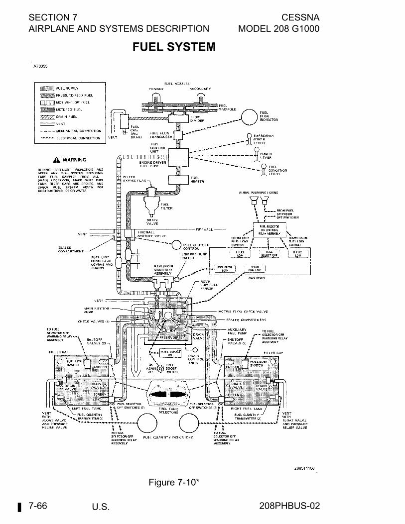
SECTION 7 CESSNAAIRPLANE AND SYSTEMS DESCRIPTION MODEL 208 G1000
U.S.7-66
FUEL SYSTEM
Figure 7-10*
208PHBUS-02
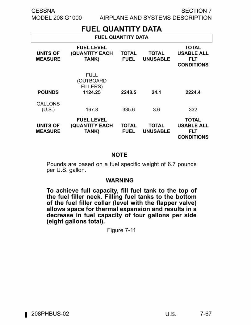
CESSNA SECTION 7MODEL 208 G1000 AIRPLANE AND SYSTEMS DESCRIPTION
U.S. 7-67
FUEL QUANTITY DATAFUEL QUANTITY DATA
UNITS OF MEASURE
FUEL LEVEL (QUANTITY EACH
TANK)TOTAL FUEL
TOTAL UNUSABLE
TOTAL USABLE ALL
FLT CONDITIONS
POUNDS
GALLONS(U.S.)
FULL(OUTBOARD
FILLERS)1124.25
167.8
2248.5
335.6
24.1
3.6
2224.4
332
UNITS OF MEASURE
FUEL LEVEL (QUANTITY EACH
TANK)TOTAL FUEL
TOTAL UNUSABLE
TOTAL USABLE ALL
FLT CONDITIONS
NOTE
Pounds are based on a fuel specific weight of 6.7 poundsper U.S. gallon.
WARNING
To achieve full capacity, fill fuel tank to the top ofthe fuel filler neck. Filling fuel tanks to the bottomof the fuel filler collar (level with the flapper valve)allows space for thermal expansion and results in adecrease in fuel capacity of four gallons per side(eight gallons total).
Figure 7-11
208PHBUS-02
SECTION 7 CESSNAAIRPLANE AND SYSTEMS DESCRIPTION MODEL 208 G1000
U.S.7-68
FIREWALL FUEL SHUTOFF VALVEA manual firewall fuel shutoff valve, located on the aft side of thefirewall, enables the pilot to shut off all fuel flow from the fuel reservoirto the engine. The shutoff valve is controlled by a red push-pull knoblabeled FUEL SHUTOFF-PULL OFF and located on the right side ofthe pedestal. The push-pull knob has a press-to-release button in thecenter which locks the knob in position when the button is released.
FUEL TANK SELECTORSTwo FUEL SELECTORS, one for each tank, are located on theoverhead console. The selectors, labeled LEFT, ON and OFF andRIGHT, ON and OFF, mechanically control the position of the two fueltank shutoff valves at each wing tank. When a fuel tank selector is inthe OFF position, the shutoff valves in the tank are closed. When in theON position, both shutoff valves in the tank are open, allowing fuel fromthat tank to flow to the reservoir. Normal fuel management is with bothfuel tank selectors in the ON position.Before refueling, or when the airplane is parked on a slope, turn off oneof the fuel tank selectors (if parked on a slope, turn high wing tank off).This action prevents crossfeeding from the fuller or higher tank andreduces any fuel seepage tendency from the wing tank vents.
FUEL SELECTORS OFF WARNING SYSTEMA fuel selectors off warning system is incorporated to alert the pilot ifone or both of the fuel tank selectors are in the OFF positioninadvertently. The system included redundant warning horns, a RedFUEL SELECT OFF CAS MSG, annunciation of selected tank,actuation switches, and miscellaneous electrical hardware. The dualaural warning system is powered through the START CONT circuitbreaker with a non-pullable FUEL SEL WARN circuit breaker installedin series to protect the integrity of the start system.
(Continued Next Page)
208PHBUS-02
CESSNA SECTION 7MODEL 208 G1000 AIRPLANE AND SYSTEMS DESCRIPTION
U.S. 7-69
FUEL SELECTORS OFF WARNING SYSTEM (continued)
The warning system functions as follows:1. If both the left and right fuel tank selectors are in the OFF
position (fuel tank shutoff valves are closed), the Red FUELSELECT OFF CAS MSG illuminates and one of the fuel selectoroff warning horns is activated;
2. During an engine start operation (STARTER switch in START orMOTOR position) with either the left or right fuel tank selectorsin the OFF position, the Red FUEL SELECT OFF CAS MSGilluminates and both of the fuel select off warning horns areactivated;
3. With one fuel tank selector in the OFF position and fuelremaining in the tank being used is less than approximately 25gallons, the Red FUEL SELECT OFF CAS MSG illuminates andone of the fuel selector off warning horns is activated.
The warning system has the ability to annunciate which fuel selector isselected off by displaying OFF next to the respective fuel quantityindicator on the EIS. There is no annunciation when the fuel selector isturned ON.If the FUEL SEL WARN circuit breaker has popped or the STARTCONT circuit breaker has been pulled (possible for groundmaintenance), the Red FUEL SELECT OFF CAS MSG will beilluminated even with both fuel tank selectors ON. This is a warning tothe pilot that the fuel selector warning system has been deactivated.A test switch, labeled TEST SWITCH, FUEL SELECT OFF - DN, islocated on the lower left corner of the instrument panel. When thisswitch is placed in the DOWN position, the two warning horns willsound simultaneously indicating that the fuel selector warning circuitryhorns are operational.
FUEL BOOST PUMP SWITCHAn auxiliary boost pump switch, located on the left sidewall switch andcircuit breaker panel, is labeled FUEL BOOST and has OFF, NORM,and ON positions. When the switch is in the OFF position, the auxiliaryboost pump is inoperative. When the switch is in the NORM position,the auxiliary boost pump is armed and will operate when fuel pressurein the fuel manifold assembly drops below 4.75 psi. This switch positionis used for all normal engine operation where main fuel flow is providedby the ejector boost pump and the auxiliary boost pump is used as astandby. When the auxiliary boost pump switch is placed in the ONposition, the auxiliary boost pump will operate continuously. Thisposition is used for engine start and any other time that the auxiliaryboost pump cycles on and off with the switch in the NORM position,and for all operations utilizing aviation gasoline.
208PHBUS-02
SECTION 7 CESSNAAIRPLANE AND SYSTEMS DESCRIPTION MODEL 208 G1000
U.S.7-70
FUEL FLOW INDICATION
A fuel flow indicator, located beneath the quantity indicators on both theENGINE and SYSTEM pages, indicates the fuel consumption of theengine in pounds per hour based on Jet A fuel. The indicator measuresthe flow of fuel downstream of the fuel control unit just before beingrouted into the flow divider. The fuel flow indicator receives power froma pull-off type circuit breaker labeled F FLOW NP & NG, on the leftsidewall switch and circuit breaker panel.
FUEL QUANTITY INDICATIONSFuel quantity is measured by four fuel quantity transmitters (two in eachtank) and indicated by two electrically-operated fuel quantity indicatorson the upper portion of the instrument panel. The fuel quantityindicators, which measure volume, are calibrated in pounds (based onthe weight of Jet A fuel on a standard day). An empty tank is indicatedby a red line and the letter E. When an indicator shows an empty tank,approximately 2.8 gallons remain in the tank as unusable fuel. The leftand right fuel quantity indicators each receive power from a pull-off typecircuit breaker. The breakers are labeled LEFT FUEL QTY and RIGHTFUEL QTY, respectively, and are located on the left sidewall switch andcircuit breaker panel.
WARNING
Because of the relatively long fuel tanks, fuelquantity indicator accuracy is affected byuncoordinated flight or a sloping ramp if readingthe indicators while on the ground. Therefore, toobtain accurate fuel quantity readings, verify thatthe airplane is parked in a laterally level condition,or if in flight, make sure the airplane is in acoordinated and stabilized condition.
WING TANK FUEL LOW CAUTION CAS MESSAGESTwo float sensors one for each wing tank will trigger the appropriateamber CAS message, L FUEL LEVEL LOW or R FUEL LEVEL LOWMSG. when the fuel in the respective tank is 25 gallons (170 lbs) orless. When the fuel quantity in each tank is less than 25 gallons (170lbs), amber L-R FUEL LEVEL LOW CAS MSG will replace thepreviously displayed L or R FUEL LEVEL LOW CAS message.
208PHBUS-02
CESSNA SECTION 7MODEL 208 G1000 AIRPLANE AND SYSTEMS DESCRIPTION
U.S. 7-71
RESERVOIR FUEL LOW WARNING CAS MESSAGEA Red RSVR FUEL LOW CAS MSG is located on the PFD, and willilluminate when the level of fuel in the reservoir drops to approximatelyone-half full. With the fuel reservoir full, there is adequate fuel forapproximately 3 minutes of maximum continuous power orapproximately 9 minutes at idle power.
FUEL PRESSURE LOW WARNING CAS MESSAGEAn Amber FUEL PRESS LOW CAS MSG is located on the PFD, andwill illuminate when fuel pressure in the reservoir fuel manifoldassembly is below 4.75 psi.
FUEL BOOST PUMP ON CAS MESSAGEAn Amber FUEL BOOST ON CAS MSG is located on the PFD and willilluminate when the auxiliary boost pump is operating, such as whenthe auxiliary boost pump Switch is placed in the ON position or whenthe auxiliary boost pump Switch is in the NORM position and fuelpressure in the fuel manifold assembly drops below 4.75 psi.
DRAIN VALVESThe fuel system is equipped with drain valves to provide a means forthe examination of fuel in the system for contamination and grade.Drain valves are located on the lower surface of each wing at theinboard end of the fuel tank, in fuel tank external sumps, on the left sideof the cargo pod for the reservoir tank, and on the underside of the fuelfilter. Outboard fuel tank drain valves and their use is recommended ifthe airplane is parked with one wing low on a sloping ramp. The drainvalves for the wing tanks and their external sumps are tool-operatedpoppet type and are flush-external mounted. The wing tank andexternal sump drain valves are constructed so that the Phillipsscrewdriver on the fuel sampler which is provided can be utilized todepress the valve and then twist to lock the drain valve in the openposition. The drain valve for the reservoir is controlled by a double-button push-pull drain control knob. When pulled out, fuel from thereservoir drains out the rear fuel drain pipe located adjacent to the drainvalve. The drain valve for the fuel filter consists of a drain pipe whichcan be depressed upward to drain fuel from the filter. The fuel samplercan be used in conjunction with these drain valves for fuel samplingand purging of the fuel system. The fuel tanks should be filled aftereach flight when practical to minimize condensation.
(Continued Next Page)
208PHBUS-02
SECTION 7 CESSNAAIRPLANE AND SYSTEMS DESCRIPTION MODEL 208 G1000
U.S.7-72
DRAIN VALVES (Continued)
Before each flight of the day and after each refueling, use a clearsampler and drain fuel from the inboard fuel tank sump, external sumpquick-drain valves, fuel reservoir quick-drain valve, and fuel filter quick-drain valve to determine if contaminants are present, and that theairplane has been fueled with the proper fuel. If the airplane is parkedwith one wing low on a sloping ramp, draining of the outboard fuel tanksump quick-drain valves is also recommended. If contamination isdetected, drain all fuel drain points again. Take repeated samples fromall fuel drain points until all contamination has been removed. If afterrepeated sampling, evidence of contamination still exists, the fuel tanksshould be completely drained and the fuel system cleaned. Do not flythe airplane with contaminated or unapproved fuel.
WARNING
JP-4 and other NAPHTHA based fuels can causesevere skin and eye irritation.
FUEL DRAIN CANWhen the engine is shut down, residual fuel in the engine drains into afuel drain can mounted on the front left side of the firewall. This canshould be drained once a day or at an interval not to exceed six engineshutdowns. A drain valve on the bottom side of the cowling enables thepilot to drain the contents of the fuel drain can into a suitable container.
FUEL PUMP DRAIN RESERVOIRTo control expended lubricating oil from the engine fuel pump drivecoupling area and provide a way to determine if fuel is leaking past thefuel pump seal, this airplanes is equipped with a drainable reservoir tocollect this allowable discharge of oil and any fuel seepage. Thereservoir is mounted on the front left side of the firewall. It should bedrained once a day or at an interval not to exceed six engineshutdowns. A drain valve on the bottom side of the cowling enables thepilot to drain the contents of the reservoir into a suitable container. Aquantity of up to 3 cc of oil and 20 cc of fuel discharge per hour ofengine operation is allowable. If the quantity of oil or fuel drained fromthe reservoir is greater than specified, the source of leakage should beidentified and corrected prior to further flight.
208PHBUS-02
CESSNA SECTION 7MODEL 208 G1000 AIRPLANE AND SYSTEMS DESCRIPTION
U.S. 7-73
BRAKE SYSTEMThe airplane has a single-disc, hydraulically-actuated brake on eachmain landing gear wheel. Each brake is connected, by a hydraulic line,to a master cylinder attached to each of the pilot's rudder pedals. Thebrakes are operated by applying pressure to the top of either the left(pilot's) or right (copilot's) set of rudder pedals, which areinterconnected. When the airplane is parked, both main wheel brakesmay be set by utilizing the parking brake which is operated by a handlebelow to the right of the pilot’s control wheel. To apply the parkingbrake, set the brakes with the rudder pedals and pull the handle aft. Torelease the parking brake, push the handle fully in.A brake fluid reservoir, located just forward of the firewall on the leftside of the engine compartment, provides additional brake fluid for thebrake master cylinders. The fluid in the reservoir should be checked forproper level prior to each flight.For maximum brake life, keep the brake system properly maintained.Airplanes are equipped with metallic type brakes, and require a specialbrake burn-in before delivery (or after brake replacement). Whenconditions permit, hard brake application is beneficial in that theresulting higher brake temperatures tend to maintain proper brakeglazing and will prolong the expected brake life. Conversely, thehabitual use of light and conservative brake application is detrimental tometallic brakes.Some of the symptoms of impending brake failure are: gradualdecrease in braking action after brake application, noisy or draggingbrakes, soft or spongy pedals, and excessive travel and weak brakingaction. If any of these symptoms appear, the brake system is in need ofimmediate attention. If, during taxi or landing roll, braking actiondecreases, let up on the pedals and then re-apply the brakes withheavy pressure. If the brakes become spongy or pedal travelincreases, pumping the pedals should build braking pressure. If onebrake becomes weak or fails, use the other brake sparingly while usingopposite rudder, as required, to offset the good brake.
208PHBUS-02

SECTION 7 CESSNAAIRPLANE AND SYSTEMS DESCRIPTION MODEL 208 G1000
U.S.7-74
ELECTRICAL SYSTEMThe airplane is equipped with a 28-volt, direct-current electrical system(see Typical Electrical System figure). The system uses a 24-voltsealed lead acid battery; located on the front right side of the firewall,as a source of electrical energy. A 200-amp engine-driven starter-generator is used to maintain the battery's state of charge. Power issupplied to most general electrical and all avionics circuits through twogeneral buses, two avionics buses, and a hot battery bus. The batterybus is energized continuously for cabin/courtesy lights and functionsrequiring power when the two general busses are off. The two generalbuses are on anytime the battery switch is turned on. All DC buses areon anytime the battery switch and the two avionics switches are turnedon.
STANDBY ELECTRICAL SYSTEMThe standby electrical system serves as a power source in the eventthe main generator system malfunctions in flight. The system includesan alternator operated at a 75-amp capacity rating. The alternator isbelt-driven from an accessory pad on the rear of the engine. Thesystem also includes an alternator control unit located forward of thecircuit breaker panel, a standby alternator contactor assembly on theleft front side of the firewall and two switches on the left sidewall switchpanel, labeled STBY ALT POWER and AVIONICS STBY PWR.Circuit protection and isolation is provided by two circuit breakers,labeled STBY PWR, on the left sidewall circuit breaker panel. Fieldexcitation to the alternator control unit is supplied through diode logicfrom a circuit breaker in the standby alternator relay assembly or fromthe HOURMETER/ACU circuit breaker in the main power relay box.Standby Electrical system monitoring is provided by CAS messages;White STBY PWR ON CAS MSG and Amber STBY PWR INOP CASMSG. Total amperage supplied from the standby electrical system canbe monitored on the EIS SYSTEMS DISPLAY. Additionally, an ALTNRAMPS CAS message is provided if the standby alternator amperagedraw exceeds normal operating ranges.
208PHBUS-02

CESSNA SECTION 7MODEL 208 G1000 AIRPLANE AND SYSTEMS DESCRIPTION
U.S. 7-75
GENERATOR CONTROL UNITThe generator control unit (GCU) is mounted inside the cabin on the leftforward fuselage sidewall. The unit provides the electrical controlfunctions necessary for the operation of the starter-generator. The GCUprovides for automatic starter cutoff when engine RPM is above 46%.Below 46%, the starter-generator functions as a starter, and above46%, the starter-generator functions as a generator when the starterswitch is OFF. The GCU provides voltage regulation plus high voltageprotection and reverse current protection. In the event of a high-voltageor reverse current condition, the generator is automaticallydisconnected from the buses. The generator contactor (controlled bythe GCU) connects the generator output to the airplane bus. If anyGCU function causes the generator contactor to de-energize, theAmber GENERATOR OFF CAS MSG will illuminate.
GROUND POWER MONITORThe ground power monitor is located inside the electrical power controlassembly mounted on the left hand side of the firewall in the enginecompartment. This unit senses the voltage level applied to the externalpower receptacle and will close the external power contactor when theapplied voltage is within the proper limits.
BATTERY SWITCHThe battery switch is a two-position toggle-type switch, labeledBATTERY, and is located on the left sidewall switch and circuit breakerpanel. The battery switch is ON in the forward position and OFF in theaft position. When the battery switch is in the ON position, batterypower is supplied to the two general buses. The OFF position cuts offpower to all buses except the battery bus.
208PHBUS-02

SECTION 7 CESSNAAIRPLANE AND SYSTEMS DESCRIPTION MODEL 208 G1000
U.S.7-76
STARTER SWITCHThe starter switch is a three-position toggle-type switch, labeledSTARTER, on the left sidewall switch and circuit breaker panel. Theswitch has OFF, START, and MOTOR positions. For additional detailsof the starter switch, refer to the Starting System paragraph in thissection.
IGNITION SWITCHThe ignition switch is a two-position toggle-type switch, labeledIGNITION, on the left sidewall switch and circuit breaker panel. Theswitch has ON and NORMAL positions. For additional details of theignition switch, refer to the Ignition System paragraph in this section.
GENERATOR SWITCHThe generator switch is a three-position toggle-type switch, labeledGENERATOR, on the left sidewall switch and circuit breaker panel. Theswitch has ON, RESET, and TRIP positions. With the switch in the ONposition, the GCU will automatically control the generator line contactorfor normal generator operation. The RESET and TRIP positions aremomentary positions and are spring-loaded to the ON position. If amomentary fault should occur in the generating system (as evidencedby the Amber GENERATOR OFF CAS MSG, Red VOLTAGE LOW CASMSG and/or Red VOLTAGE HIGH CAS MSG), the generator switchcan be momentarily placed in the RESET position to restore generatorpower. If erratic operation of the generating system is observed, thesystem can be shutoff by momentarily placing the generator switch tothe TRIP position. After a suitable waiting period, generator operationmay be recycled by placing the generator switch momentarily toRESET.
STANDBY ALTERNATOR POWER SWITCHThe standby alternator system switch is a two-position toggle-typeswitch, labeled STBY ALT POWER. There is also an amber LED abovethe switch that illuminates when the BATTERY switch is in the OFFposition with STBY ALT POWER in the ON position. This is an alert tothe operator to help prevent accidental discharging of the battery thatcan occur if the STBY ALT POWER switch is left ON after shutdown.
208PHBUS-02
CESSNA SECTION 7MODEL 208 G1000 AIRPLANE AND SYSTEMS DESCRIPTION
U.S. 7-77
AVIONICS POWER SWITCHESElectrical power from the airplane power distribution bus to the avionicsbuses (see Typical Electrical System figure) is controlled by two toggle-type switch breakers located on the left sidewall switch and circuitbreaker panel. One switch controls power to the number 1 avionics buswhile the other switch controls power to the number 2 avionics bus. Theswitches are labeled AVIONICS and are ON in the forward position andOFF in the aft position. The avionics power switches should be placedin the OFF position prior to turning the battery switch ON or OFF, orapplying an external power source. The number 1 AVIONICS Switchmust be ON prior to engine start to display EIS information.
AVIONICS STANDBY POWER SWITCHThe avionics standby power system switch is a guarded two-positionswitch/breaker, labeled AVIONICS STBY PWR. The guard coveringthis switch must be lifted in order to select the ON position. Whenswitched ON, the standby electrical system directly provides power tothe Avionics bus 1. When switched OFF, the standby electrical systemmay provide extra power to the avionics busses via the main powerdistribution bus, provided the STBY PWR circuit breakers on theelectrical busses are not pulled. When operating solely on standbypower, both AVIONICS 1 and 2 power switches should be OFF to avoidfeeding a possible fault in the primary power system.
AVIONICS BUS TIE SWITCHThe avionics bus tie switch is a two-position guarded toggle-type switchlocated on the left sidewall switch and circuit breaker panel. The switchconnects the number 1 and number 2 avionics buses together in theevent of failure of either bus feeder circuit. Because power for eachavionics bus is supplied from a separate current limiter on the powerdistribution bus, failure of a current limiter can cause failure of theaffected bus. Placing the bus tie switch to the ON position will restorepower to the failed bus. Operation without both bus feeder circuits mayrequire an avionics load reduction, depending on equipment installed.
208PHBUS-02
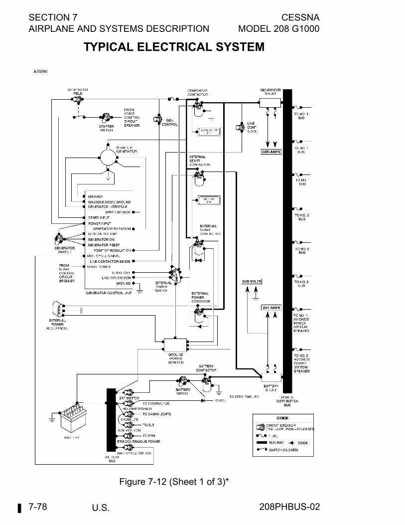
SECTION 7 CESSNAAIRPLANE AND SYSTEMS DESCRIPTION MODEL 208 G1000
U.S.7-78
TYPICAL ELECTRICAL SYSTEM
Figure 7-12 (Sheet 1 of 3)*
208PHBUS-02
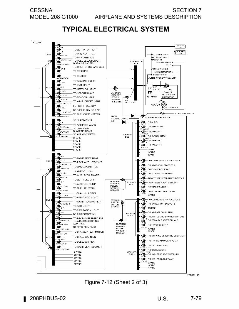
CESSNA SECTION 7MODEL 208 G1000 AIRPLANE AND SYSTEMS DESCRIPTION
U.S. 7-79
TYPICAL ELECTRICAL SYSTEM
Figure 7-12 (Sheet 2 of 3)
208PHBUS-02
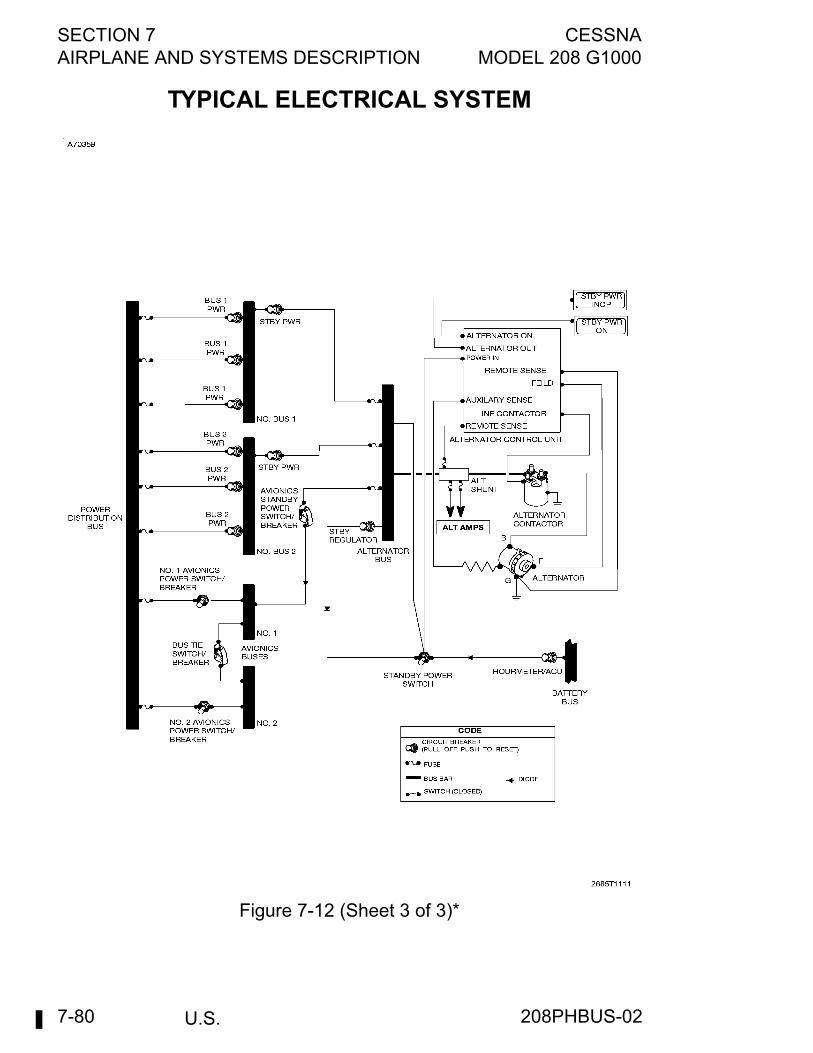
SECTION 7 CESSNAAIRPLANE AND SYSTEMS DESCRIPTION MODEL 208 G1000
U.S.7-80
TYPICAL ELECTRICAL SYSTEM
Figure 7-12 (Sheet 3 of 3)*
208PHBUS-02
CESSNA SECTION 7MODEL 208 G1000 AIRPLANE AND SYSTEMS DESCRIPTION
U.S. 7-81
EXTERNAL POWER SWITCHThe external power switch is a three-position guarded toggle-typeswitch located on the left sidewall switch and circuit breaker panel. Theswitch has OFF, STARTER, and BUS positions and is guarded in theOFF position. When the switch is in the OFF position, battery power issupplied to the main bus and to the starter-generator circuit, externalpower cannot be applied to the main bus, and, with the generatorswitch in the ON position, power is applied to the generator controlcircuit. When the external power switch is in the STARTER position,external power is applied to the starter circuit only and battery power issupplied to the main bus. No generator power is available in thisposition. When the external power switch is in the BUS position,external power is applied to the main bus and no power is available tothe starter. The battery, if desired, can be connected to the main busand external power by the battery switch; however, battery chargeshould be monitored to avoid overcharge.
CIRCUIT BREAKERSMost of the electrical circuits in the airplane are protected by pull-offtype circuit breakers mounted on the left sidewall switch and circuitbreaker panel. Should an overload occur in any circuit, the controllingcircuit breaker will trip, opening the circuit. After allowing the circuitbreaker to cool for approximately three minutes, it may be reset(pushed in). If the breaker trips again, it should not be reset untilcorrective action is taken.
WARNING
Make sure all circuit breakers are in before allflights. Never operate with tripped circuit breakerswithout a thorough knowledge of theconsequences.
VOLTAGE AND AMPERAGE DISPLAYThe status of the electrical system can be monitored on the MFD (non-reversionary mode). Battery current (BAT AMPS) and bus voltage(BUS VOLTS) are displayed on the default EIS-ENGINE display page.By pressing the ENGINE softkey and the SYSTEM softkey, the EISpages changes to the EIS-Systems display where generator current(GEN AMPS), and bus voltage (BUS VOLTS) can be monitoredsimultaneously. A negative display on BAT AMPS indicates batterydischarge, while a positive display indicates battery charging.
208PHBUS-02
SECTION 7 CESSNAAIRPLANE AND SYSTEMS DESCRIPTION MODEL 208 G1000
U.S.7-82
GROUND SERVICE PLUG RECEPTACLEA ground service plug receptacle permits the use of an external powersource for cold weather starting and during lengthy maintenance workon the electrical and avionics equipment. External power controlcircuitry is provided to prevent the external power and the battery frombeing connected together during starting. The external powerreceptacle is installed on the left side of the engine compartment nearthe firewall.The ground service circuit incorporates polarity reversal andovervoltage protection. Power from the external power source will flowonly if the ground service plug is correctly connected to the airplane. Ifthe plug is accidentally connected backwards or the ground servicevoltage is too high, no power will flow to the electrical system, therebypreventing any damage to electrical equipment.
LIGHTING SYSTEMS
EXTERIOR LIGHTINGExterior lighting consists of three navigation lights, two landing lights,two taxi/recognition lights, two strobe lights, a flashing beacon, and twounderwing courtesy lights. All exterior lights are controlled by toggleswitches located on the lighting control panel on the left side of theinstrument panel. The toggle switches are ON in the up position andOFF in the down position.
NAVIGATION LIGHTSConventional navigation lights are installed on the wing tips andtailcone stinger. The lights are protected by a pull-off type circuitbreaker, labeled NAV LIGHT, on the left sidewall switch and circuitbreaker panel.
208PHBUS-02
CESSNA SECTION 7MODEL 208 G1000 AIRPLANE AND SYSTEMS DESCRIPTION
U.S. 7-83
LANDING LIGHTSTwo landing lights are installed on the airplane, one in each wingleading edge mounted outboard. The lights provide illumination forwardand downward during takeoff and landing. The lights are protected bytwo pull-off type circuit breakers, labeled LEFT LDG LIGHT and RIGHTLDG LIGHT, on the left sidewall switch and circuit breaker panel.
NOTE
It is not recommended that the landing lights be used toenhance the conspicuity of the airplane in the traffic patternor enroute, because of their relatively short service life. thetaxi/recognition lights have considerably longer service lifeand are designed for this purpose, if desired.
TAXI/RECOGNITION LIGHTSTwo taxi/recognition lights are mounted inboard of each landing light ineach wing leading edge. The lights are focused to provide illuminationof the area forward of the airplane during ground operation and taxiing.the lights are also used to enhance the conspicuity of the airplane in thetraffic pattern or enroute. The taxi/recognition lights are protected by apull-off type circuit breaker, labeled TAXI LIGHT, on the left sidewallswitch and circuit breaker panel.
STROBE LIGHTSA high intensity strobe light system is installed on the airplane. Thesystem includes two strobe lights (with remote power supplies) locatedone on each wing tip. The lights are used to enhance anti-collisionprotection for the airplane and are required anti-collision lights for nightoperations. The strobe lights are protected by a pull-off type circuitbreaker, labeled STROBE LIGHT, on the left sidewall switch and circuitbreaker panel.
WARNING
Strobe lights should be turned off when taxiing.Ground operation of the high intensity anti-collision lights can be considerable annoyance toground personnel and other pilots. Do not operatethe anti-collision lights in conditions of fog, clouds,or haze as the reflection of the light beam cancause disorientation or vertigo.
208PHBUS-02
SECTION 7 CESSNAAIRPLANE AND SYSTEMS DESCRIPTION MODEL 208 G1000
U.S.7-84
FLASHING BEACON LIGHTA red flashing beacon light is installed on the top of the vertical fin asadditional anti-collision protection in flight and for recognition duringground operation. The light is visible through 360°. The flashing beaconlight circuit is protected by a pull-off type circuit breaker, labeledBEACON LIGHT, on the left sidewall switch and circuit breaker panel.
WARNING
The flashing beacon should not be used whenflying through clouds or overcast; the flashing lightreflected from water droplets or particles in theatmosphere, particularly at night, can causedisorientation or vertigo.
COURTESY LIGHTSTwo courtesy lights are installed, one under each wing. The lightsilluminate the area outside of the airplane adjacent to the crew entrydoors. The lights operate in conjunction with the cabin lights and arecontrolled by the cabin light switches as described in the Cabin Lightsparagraph in this section.
INTERIOR LIGHTINGInstrument and control panel lighting is provided by integral, flood andpost lights. Six lighting control knobs are grouped together on the lowerpart of the instrument panel to the left of the control pedestal. Thesecontrols vary the intensity of the lighting for the instrument panel,pedestal, overhead panel, left sidewall panel, LED panels, Garmindisplays, and internally lit instruments. The following paragraphsdescribe the function of these controls. The circuits for these lights areprotected by two pull-off type circuit breakers, labeled AVN/FLOODLIGHT and INST LIGHT, on the left sidewall switch and circuit breakerpanel. Other miscellaneous lighting provided or available includescontrol wheel map lights, cabin lights, passenger reading lights, and ano smoking/seat belt sign. Discussion of these lights and their controlsis also included in the following paragraphs.
GARMIN DISPLAYS, OPTIONAL ADF, AND HF DISPLAYS (ifinstalled)The knob labeled AVIONICS varies the intensity of the Garmin andoptional displays (if installed). Clockwise rotation of the knob increasesdisplay brightness and counterclockwise rotation decreases brightness.The displays cannot be dimmed to full dark. Rotating this knobcounterclockwise past the dimmest setting will place the displays inphotosensitive mode.
208PHBUS-02

CESSNA SECTION 7MODEL 208 G1000 AIRPLANE AND SYSTEMS DESCRIPTION
U.S. 7-85
STANDBY INDICATOR CONTROL KNOBThe knob labeled STANDBY IND varies the intensity of the integrallighting of the standby airspeed indicator, attitude indicator, altimeter,torque indicator, and magnetic compass. Clockwise rotation of the knobincreases light brightness and counterclockwise rotation decreasesbrightness.
SWITCH/CIRCUIT BREAKER PANEL CONTROL KNOBThe knob labeled SW/CB PANELS varies the intensity of the backlitLED panels. These panels are inscribed with labels for most of theswitches, controls, and circuit breakers mounted on the instrumentpanel. Clockwise rotation of the knob increases panel brightness andcounterclockwise rotation decreases brightness.
CIRCUIT BREAKER/PEDESTAL/OVERHEAD PANEL KNOBThe knob labeled CB/PED/OVHD varies the intensity of the lights thatilluminate the left sidewall switch and circuit breaker panel, the floodlight that illuminates the control pedestal, and the post lights thatilluminate the overhead panel. Clockwise rotation of the knob increasespanel brightness and counterclockwise rotation decreases brightness.
LEFT FLOOD LIGHTING CONTROL KNOBThis knob labeled LEFT FLOOD varies the brightness of the left sidefloodlight located on the right aft side of the overhead panel. Thisfloodlight may also be used to illuminate the left sidewall switch andcircuit breaker panel. Clockwise rotation of this control knob increaseslamp brightness while counterclockwise rotation decreases brightness.
RIGHT FLOOD LIGHTING CONTROL KNOBThis knob labeled RIGHT FLOOD varies the brightness of the right sidefloodlight located on the left aft side of the overhead panel. Clockwiserotation of this control knob increases lamp brightness whilecounterclockwise rotation decreases brightness.
CONTROL WHEEL MAPLIGHTSA control wheel maplight is mounted on the bottom of each controlwheel. These lights illuminate the lower portion of the cabin in front ofthe pilot and copilot, and are used for checking maps and other flightdata during night operation. Brightness of these lights is adjusted with arheostat control knob on the bottom of the control wheel. Rotating thenear side of the knob to the right increases light brightness and to theleft decreases brightness.
208PHBUS-02
SECTION 7 CESSNAAIRPLANE AND SYSTEMS DESCRIPTION MODEL 208 G1000
U.S.7-86
CABIN LIGHTS WITHOUT TIMERThe 208 cabin light system consists of three cabin lights installed on theinterior of the airplane and courtesy lights under each wing to facilitateboarding or loading cargo during night operations. One light is locatedabove the center cabin area, one above the aft cargo door, and oneabove the aft passenger door. Controls for the lighting system consists of one 2-way toggle switchlabeled CABIN on the lighting control panel as well as a rocker switchjust forward of both the aft passenger and cargo doors. All three ofthese switches will toggle all cabin on or off at any time regardless ofthe other switch positions.The circuit for the cabin lights is protected by a "pull-off" type circuitbreaker, labeled CABIN LTS, on the J-Box panel in the engine bay.
CABIN LIGHTS WITH TIMER (if installed)The 208 cabin light system with timer consists of three cabin lightsinstalled on the interior of the airplane and courtesy lights under eachwing to facilitate boarding or loading cargo during night operations. Onelight is located above the center cabin area, one above the aft cargodoor, and one above the aft passenger door.Controls for the lighting system consists of one 3-way momentaryswitch labeled CABIN on the lighting control panel as well as a rockerswitch just forward of both the aft passenger and cargo doors. Thepassenger door toggle switch will control all lights except the cargodoor light, while the cargo door toggle switch will control only the cargodoor light. The 3-way momentary switch labeled CABIN on the lightingcontrol panel will control all lights regardless of the other switchpositions.The timer circuitry includes a solid state timer that will turn off all lightsafter 30 minutes automatically unless they are switched off manually.The circuit for the cabin lights is protected by a pull-off type circuitbreaker, labeled CABIN LTS, on the J-Box panel in the engine bay.
PASSENGER READING LIGHTS (Passenger Version Only)Passenger reading lights may be installed near each of the aftpassengers positions. The lights are located in 14 small conveniencepanels above each seat. A pushbutton-type ON, OFF switch, mountedin each panel, controls the lights. The lights can be pivoted in theirmounting sockets to provide the most comfortable angle of illuminationfor the passenger.
208PHBUS-02

CESSNA SECTION 7MODEL 208 G1000 AIRPLANE AND SYSTEMS DESCRIPTION
U.S. 7-87
NO SMOKE/SEAT BELT SIGN (Passenger Version Only)A lighted warning sign may be installed in the airplane to facilitatewarning passengers of impending flight operations necessitating thefastening of seat belts and/or the extinguishing of all smoking materials.This installation consists of a small lighted panel mounted in the cabinheadliner immediately aft of the overhead console and two toggle-typeswitches, labeled SEAT BELT and NO SMOKE, on the lighting controlpanel. When these switches are placed in the ON position, the warningsigns illuminate, displaying the international graphic symbolism forfasten seat belts and no smoking to the rear cabin passengers. Thecircuit for the warning sign lights is protected by a pull-off type circuitbreaker, labeled SEAT BELT SIGN, on the left sidewall switch andcircuit breaker panel.
CABIN HEATING, VENTILATING AND DEFROSTINGSYSTEMThe temperature and volume of airflow to the cabin is regulated by thecabin heating, ventilating and defrosting system (see Cabin Heating,Ventilating and Defrosting System figure). In the heating system, hotcompressor outlet air is routed from the engine through a flow controlvalve, then through a mixer/muffler where it is mixed with cabin returnair or warm air from the compressor bleed valve (depending on thesetting of the mixing air valve) to obtain the correct air temperaturebefore the air is routed to the cabin air distribution system. Controls areprovided to direct the heated air to the forward and/or aft portions of thecabin for heating and to the windshield for defrosting. Ventilating air isobtained from an inlet on each side at the forward fuselage and throughtwo ram air inlets, one on each wing at the upper end of the wing struts.The wing inlet ventilating air is routed through the wing into a plenumchamber located in the center of the cabin top. The plenum distributesthe ventilating air to individual overhead outlets near each seatposition. Two electric blowers are available for the overhead ventilatingsystem. Details of this installation are presented in Section 9,Supplements.
208PHBUS-02
SECTION 7 CESSNAAIRPLANE AND SYSTEMS DESCRIPTION MODEL 208 G1000
U.S.7-88
BLEED AIR HEAT SWITCHA two-position toggle switch, labeled BLEED AIR HEAT, is located onthe cabin heat switch and control panel. The switch controls theoperation of the bleed air flow control valve. The ON position of theswitch opens the flow control valve, allowing hot bleed air to flow to thecabin heating system. The OFF position (down) closes the valve,shutting off flow of hot bleed air to the heating system.
TEMPERATURE SELECTOR KNOBA rotary temperature selector knob, labeled TEMP, is located on thecabin heat switch and control panel. The selector modulates theopening and closing action of the flow control valve to control theamount and temperature of air flowing into the cabin. Clockwiserotation of the knob increases the mass flow and temperature of the air.
NOTE
• If more cabin heat is needed while on the ground, movethe FUEL CONDITION Lever to HIGH IDLE and/orselect the GRD position (pulled out) of the mixing aircontrol.
• Some hysteresis may be encountered when adjustingbleed air temperature. The resulting amount andtemperature of bleed air may be different whenapproaching a particular temperature selector knobposition from a clockwise versus a counterclockwisedirection. Best results can usually be obtained by turningthe temperature selector knob full clockwise and thenslowly turning it counterclockwise to decrease bleedairflow to the desired amount.
A temperature sensor, located in the outlet duct from the mixer/muffleroperates in conjunction with the temperature selector knob. In theevent of a high temperature condition (overheat) in the outlet duct, thetemperature sensor will be energized, closing the flow control valve andthus shutting off the source of hot bleed air from the engine.
208PHBUS-02
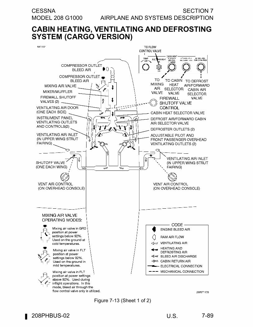
CESSNA SECTION 7MODEL 208 G1000 AIRPLANE AND SYSTEMS DESCRIPTION
U.S. 7-89
CABIN HEATING, VENTILATING AND DEFROSTING SYSTEM (CARGO VERSION)
Figure 7-13 (Sheet 1 of 2)
208PHBUS-02
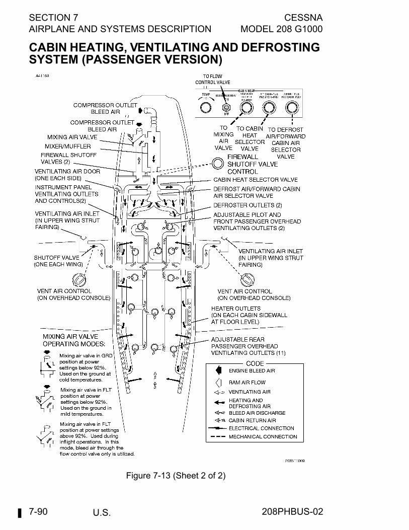
SECTION 7 CESSNAAIRPLANE AND SYSTEMS DESCRIPTION MODEL 208 G1000
U.S.7-90
CABIN HEATING, VENTILATING AND DEFROSTING SYSTEM (PASSENGER VERSION)
Figure 7-13 (Sheet 2 of 2)
208PHBUS-02

CESSNA SECTION 7MODEL 208 G1000 AIRPLANE AND SYSTEMS DESCRIPTION
U.S. 7-91
MIXING AIR PUSH-PULL CONTROLA push-pull control, labeled MIXING AIR, GRD-PULL, FLT-PUSH, islocated on the cabin heat switch and control panel. With the push-pullcontrol in the GRD position (pulled out), warm compressor bleed valveair is mixed with hot compressor outlet air in the mixer/muffler. Thismode is used during ground operation when warm compressor bleedvalve air is available (at power setting below 92% Ng) and can be usedas additional bleed air heat to augment the hot compressor outlet bleedair supply during periods of cold ambient temperature. With the push-pull control in the FLT position (pushed in), cabin return air is mixedwith the hot compressor outlet air in the mixer/muffler. This recirculationof cabin return air enables the heating system to maintain the desiredtemperature for proper cabin heating. If desired, the FLT position of thepush-pull control can be used on the ground when ambienttemperatures are mild and maximum heating is not required. In thismode, the excess warm compressor bleed valve air available at powersettings below 92% Ng is exhausted overboard from the mixing airvalve.
CAUTION
The mixing air push-pull control should always be in theFLT position (pushed in) when the airplane is in flight.Cabin return air must be allowed to flow through themixing valve and blend with hot compressor outlet airduring high engine power operation in order to maintainproper temperature in the cabin heat distributionsystem. If the FLT position is not used during flight, thesystem may overheat and cause an automaticshutdown.
208PHBUS-02
SECTION 7 CESSNAAIRPLANE AND SYSTEMS DESCRIPTION MODEL 208 G1000
U.S.7-92
AFT/FORWARD CABIN PUSH-PULL CONTROLA push-pull control, labeled AFT CABIN-PULL, FWD CABIN-PUSH, islocated on the cabin heat switch and control panel. With the control inthe AFT CABIN position (pulled out), heated air is directed to the aftcabin heater outlets located on the cabin sidewalls at floor level on thePassenger Version 208 and the outlets in the floor behind the pilot andcopilot on the Cargomaster.With the control in the FWD CABIN position (pushed in), heated air isdirected to the forward cabin through four heater outlets located behindthe instrument panel and/or the two windshield defroster outlets. Thepush-pull control can be positioned at any intermediate setting desiredfor proper distribution of heated air to the forward and aft cabin areas.
DEFROST/FORWARD CABIN PUSH-PULL CONTROLA push-pull control, labeled DEFROST-PULL, FWD CABIN-PUSH, islocated on the cabin heat switch and control panel. With the control inthe DEFROST position (pulled out), forward cabin air is directed to twodefroster outlets located at the base of the windshield (the aft/forwardcabin push-pull control also must be pushed in for availability of forwardcabin air for defrosting). With the defrost/forward cabin push-pullcontrol in the FWD CABIN position (pushed in), heated air will bedirected to the four heater outlets behind the instrument panel.
CABIN HEAT FIREWALL SHUTOFF KNOBA push-pull shutoff knob, labeled CABIN HEAT FIREWALL SHUTOFF,PULL OFF, is located on the lower right side of the pedestal. Whenpulled out, the knob actuates two firewall shutoff valves, one in thebleed air supply line to the cabin heating system and one in the cabinreturn air line, to the off position. This knob should normally be pushedin unless a fire is suspected in the engine compartment.
CAUTION
Do not place the cabin heat firewall shutoff knob in theOFF position when the mixing air control is in the GRDposition because a compressor stall will occur at lowpower settings when the compressor bleed valve isopen. The engine must be shut down to relieve backpressure on the valves prior to opening the valves.
208PHBUS-02
CESSNA SECTION 7MODEL 208 G1000 AIRPLANE AND SYSTEMS DESCRIPTION
U.S. 7-93
VENT AIR CONTROL KNOBSTwo vent air control knobs, labeled VENT AIR, are located on theoverhead console. The knobs control the operation of the shutoff valvesin each wing which control the flow of ventilating air to the cabin. Theknob on the right side of the console controls the right wing shutoffvalve and similarly, the knob on the left side controls the left wingshutoff valve. When the vent air control knobs are rotated to theCLOSE position, the wing shutoff valves are closed; rotating the knobsto the OPEN position progressively opens the wing shutoff valves.When the optional cabin ventilation fans are installed, rotating theknobs to the full OPEN position also turns on the ventilation fans.
INSTRUMENT PANEL VENT KNOBSTwo vent knobs, labeled VENT, PULL ON, are located one on eachside of the instrument panel. Each knob controls the flow of ventilatingair from an outlet located adjacent to each knob. Pulling each knobopens a small air door on the fuselage exterior which pulls in ram air fordistribution through the ventilating outlet.
VENTILATING OUTLETSTwo vent knobs, labeled VENT, PULL ON, are located one on eachside of the instrument panel. Each knob controls the flow of ventilatingair from an outlet located adjacent to that knob. Pulling each knobopens a small air door on the fuselage exterior which pulls in ram air fordistribution through the ventilating outlet.
OXYGEN SYSTEMSome Cargo Versions are equipped with a two-port oxygen systemhaving quick-don type masks for the pilot and passenger; other CargoVersions can be equipped with a two-port oxygen system utilizingconventional masks. The Passenger Version can be equipped with upto 17-port oxygen system utilizing conventional masks. Refer to Section9, Supplements, for complete details and operating instructions.
208PHBUS-02
SECTION 7 CESSNAAIRPLANE AND SYSTEMS DESCRIPTION MODEL 208 G1000
U.S.7-94
PITOT-STATIC SYSTEM AND INSTRUMENTSThere are two independent pitot-static systems on the airplane. The leftpitot-static system supplies ram air pressure to Air Data Computer #1and to the standby airspeed indicator, and supplies static pressure toAir Data Computer #1 and to the standby airspeed indicator, verticalspeed indicator, and altimeter. The right pitot-static system providesram air and static pressure to Air Data Computer #2. Each system iscomposed of a heated pitot-static tube mounted on the leading edge ofthe corresponding wing, a drain valve located on the sidewall beneaththe instrument panel, and the associated plumbing necessary toconnect the instruments and sources. In addition, the left systemincludes a static pressure alternate source valve located on the lowerleft corner of the instrument panel.The static pressure alternate source valve in the left system can beused if the static source is malfunctioning. This valve supplies staticpressure from inside the cabin instead of from the pitot-static tube. Iferroneous instrument readings are suspected due to water or ice in thepressure line going to the static pressure source, the alternate sourcevalve should be pulled on. Pressures within the cabin will vary withvents open or closed. Refer to Section 5, Performance for the effect ofvarying cabin pressures on airspeed and altimeter readings.The drain valves incorporated in each system, located on the sidewallbeneath the instrument panel, are used to drain suspected moistureaccumulation by lifting the drain valve lever to the OPEN position asindicated by the placard adjacent to the valve. The valve must bereturned to the CLOSED position prior to flight.A left and right pitot-static heat system is installed to assure properairspeed indications in the event icing conditions are encountered. Thesystem is designed to prevent ice formation rather than remove it. Thepitot-static heat system consists of a heating element in eachpitot-static tube, a two-position toggle switch, labeled PITOT/STATICHEAT, on the anti-ice switch panel, and two pull-off type circuitbreakers, labeled LEFT PITOT HEAT and RIGHT PITOT HEAT, on theleft sidewall switch and circuit breaker panel. When the pitot-static heatswitch is turned on, elements in the pitot-static tubes are heatedelectrically to maintain proper operation in possible icing conditions.Both pitot and static systems are monitored by the G1000 system forinsufficient current and alerting is provided to the flight crew by a singlechime and an Amber L P/S HEAT, R P/S HEAT, or L-R P/S HEAT CASmessages.
208PHBUS-02
CESSNA SECTION 7MODEL 208 G1000 AIRPLANE AND SYSTEMS DESCRIPTION
U.S. 7-95
AIRSPEED INDICATIORSThe Garmin PFDs are the primary sources of airspeed information.Standby airspeed information is depicted by a mechanical indicatorcalibrated in knots, connected to the left pitot-static system. Limitationand range markings (in KIAS) match the markings on the PFD as listedin Section 2, Limitations. The standby airspeed indicator is a true airspeed indicator and isequipped with a knob which works in conjunction with the airspeedindicator dial in a manner similar to the operation of a flight computer.To operate the indicator, first rotate the knob until pressure altitude isaligned with outside air temperature in degrees Centigrade. To obtainpressure altitude, momentarily set the barometric scale on the altimeterto 29.92 and read pressure altitude on the altimeter. Be sure to returnthe altimeter barometric scale to the original barometric setting afterpressure altitude has been obtained. Having set the knob to correct foraltitude and temperature, read the true airspeed shown in the windowby the indicator pointer. For best accuracy, the indicated airspeedshould be corrected to calibrated airspeed by referring to the AirspeedCalibration chart in Section 5, Performance. Knowing the calibratedairspeed, read true airspeed in the window opposite the calibratedairspeed.
VERTICAL SPEED INDICATIONThe vertical speed indication on the PFDs depict airplane rate of climbor descent in feet per minute. The pointers are actuated by atmosphericpressure changes resulting from changes of altitude as supplied by thestatic sources.
ALTIMETER (STANDBY INSTRUMENT PANEL)Airplane altitude is depicted by a barometric type altimeter. A knob nearthe lower left portion of the indicator provides adjustment of theinstrument's barometric scale to the current altimeter setting.
208PHBUS-02
SECTION 7 CESSNAAIRPLANE AND SYSTEMS DESCRIPTION MODEL 208 G1000
U.S.7-96
VACUUM SYSTEM AND INSTRUMENTSA vacuum system (see Typical Vacuum System figure) provides thesuction necessary to operate the standby attitude indicator. Vacuum isobtained by passing regulated compressor outlet bleed air through avacuum ejector. Bleed air flowing through an orifice in the ejectorcreates the suction necessary to operate the indicator. The vacuumsystem consists of the bleed air pressure regulator, a vacuum ejectoron the forward left side of the firewall, a vacuum relief valve andvacuum system air filter on the aft side of the firewall, and the standbyattitude indicator.
ATTITUDE INDICATOR (Standby Instrument Panel)Standby attitude information is depicted by a vacuum-driven attitudeindicator. Bank attitude is presented by a pointer at the top of theindicator relative to the bank scale which has index marks at 10°, 20°,30°, 60°, and 90° either side of the center mark. Pitch and roll attitudesare presented by a miniature airplane superimposed over a symbolichorizon area divided into two sections by a white horizon bar. Theupper blue sky and the lower ground area have arbitrary pitchreference lines useful for pitch attitude control. A knob at the bottom ofthe instrument is provided for inflight adjustment of the miniatureairplane to the horizon bar for a more accurate flight attitude indication.
LOW-VACUUM WARNING FLAGThe standby attitude indicator includes an orange low-vacuum warningflag (GYRO) that comes into view when the vacuum is below the levelnecessary for reliable gyroscope operation.
WARNING
The orange low-vacuum warning flag (gyro) is theonly indication of the loss of the vacuum system.
208PHBUS-02
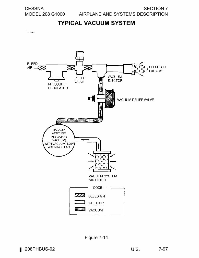
CESSNA SECTION 7MODEL 208 G1000 AIRPLANE AND SYSTEMS DESCRIPTION
U.S. 7-97
TYPICAL VACUUM SYSTEM
Figure 7-14
208PHBUS-02
SECTION 7 CESSNAAIRPLANE AND SYSTEMS DESCRIPTION MODEL 208 G1000
U.S.7-98
STALL WARNING SYSTEMThe airplane is equipped with a vane-type stall warning unit, in theleading edge of the left wing, which is electrically connected to a stallwarning horn located overhead of the pilot's position. The vane in thewing senses the change in airflow over the wing, and operates thewarning horn at airspeeds between 5 and 10 knots above the stall in allconfigurations.The stall warning system should be checked during the preflightinspection by momentarily turning on the battery switch and actuatingthe vane in the wing. The system is operational if the warning hornsounds as the vane is pushed upward. The elevator must be off theforward stop before the stall warning horn is enabled due to the factthat the aircraft is equipped with a stall warning ground disconnectswitch.A pull-off type circuit breaker, labeled STALL WRN, protects the stallwarning system. Also, it is provided to shut off the warning horn in theevent it should stick in the on position.
WARNING
This circuit breaker must be pushed in for landing.
The vane and sensor unit in the wing leading edge is equipped with aheating element. The heated part of the system is operated by theSTALL HEAT switch on the deice/anti-ice switch panel, and is protectedby the STALL WRN circuit breaker on the left sidewall switch and circuitbreaker panel.
208PHBUS-02
CESSNA SECTION 7MODEL 208 G1000 AIRPLANE AND SYSTEMS DESCRIPTION
U.S. 7-99
AVIONICS SUPPORT EQUIPMENTVarious avionics support equipment is installed in the airplane, andincludes a microphone/speaker, mic/phone jacks, avionics cooling fans,12VDC power outlets, an auxiliary audio input jack, and control surfacestatic dischargers. The following paragraphs discuss these items.Description and operation of radio equipment is covered in Section 9 ofthis POH/AFM.
AVIONICS COOLING FANTwo DC electric deck skin fans mounted on the underside of the cowldeck draw warm air from behind the instrument panel to maintainproper operating temperatures. In addition, three DC electric fans blowair directly onto the display heat sinks for prolonged equipment life. Thedeck skin fans will operate when the BATTERY switch is ON and theAVIONICS No. 1 power switch is on.
MICROPHONE-HEADSET INSTALLATIONSRadio communications are accomplished by the use of a hand-heldmicrophone and the airplane speaker, or by aviation-style headsets.The hand-held microphone stows in a hanger on the front of thepedestal and plugs into a mic jack located on the right side of thepedestal. It includes an integral push-to-talk button. The airplanespeakers are located above the pilot's and copilot's positions in thecabin headliner. The headsets plug into microphone and headset jacks located on theleft side of the instrument panel for the pilot and the right side of theinstrument panel for the copilot. Push-to-talk switches for the headsetsare mounted on the control wheels.Audio is controlled by the individual audio selector switches andadjusted for volume level by using the selected receiver volumecontrols. The system is designed so that microphones are voiceactivated, with transmission over the COM radios controlled by thepush-to-talk switches.
208PHBUS-02
SECTION 7 CESSNAAIRPLANE AND SYSTEMS DESCRIPTION MODEL 208 G1000
U.S.7-100
STATIC DISCHARGERSAs an aid in IFR flights, wick-type static dischargers are installed toimprove radio communications during flight through dust or variousforms of precipitation (rain, snow or ice crystals). Under P-Staticconditions, the build-up and discharge of static electricity from thetrailing edges of the wings, rudder, elevator, propeller tips, and radioantennas can result in loss of usable radio signals on allcommunications and navigation radio equipment. Usually the ADF isfirst to be affected and VHF communication equipment is the last to beaffected.Installation of static dischargers reduces interference from precipitationstatic, but it is possible to encounter severe precipitation staticconditions which might cause the loss of radio signals, even with staticdischargers installed. Whenever possible, avoid known severeprecipitation areas to prevent loss of dependable radio signals. Ifavoidance is impractical, minimize airspeed and anticipate temporaryloss of radio signals while in these areas.Static dischargers lose their effectiveness with age, and therefore,should be checked periodically (at least at every annual inspection) byqualified avionics technicians, etc. If testing equipment is not available,it is recommended that the wicks be replaced every two years,especially if the airplane is operated frequently in IFR conditions. Thedischarger wicks are designed to unscrew from their mounting bases tofacilitate replacement.
12VDC POWER OUTLETA power converter, located below the copilot seat, reduces theairplane's 28VDC power to 12VDC. This converter provides up to 10amps of power to operate portable devices such as notebook computerand audio players. The power output connector (POWER OUTLET12V) is located on the center pedestal (Refer to Typical InstrumentPanel figure).
208PHBUS-02
CESSNA SECTION 7MODEL 208 G1000 AIRPLANE AND SYSTEMS DESCRIPTION
U.S. 7-101
AUXILIARY AUDIO INPUT JACKAn auxiliary audio input jack (AUX AUDIO IN) is mounted on the loweraft face of the pedestal (Refer to Typical Instrument Panel figure). Itallows connection of entertainment audio devices such as cassette,compact disc, and MP3 players to play music over the airplane'sheadsets.The signal from AUX AUDIO IN is automatically muted during radiocommunications or pilot selection of crew intercom isolation modeslocated on the audio panel. The AUX key on the audio panel does notcontrol the AUX AUDIO IN signal. For a more complete description andoperating instructions of the audio panel, refer to the Garmin G1000CRG.
Since the entertainment audio input is not controlled by a switch, thereis no way to deselect the entertainment source except to disconnect thesource at the audio input connector.
CABIN FEATURES
CABIN FIRE EXTINGUISHERA portable fire extinguisher is installed on the cargo barrier in someCargo Versions and on the inside of the pilot’s entry door in other CargoVersions and the Passenger Version. The extinguisher in bothairplanes is readily accessible in case of fire. The extinguisher shouldbe checked prior to each flight to ensure that its bottle pressure, asindicated by the gage on the bottle, is within the green arc and theoperating lever lock pin is securely in place.To operate the fire extinguisher:
1. Loosen retaining clamp and remove extinguisher from bracket.2. Hold extinguisher upright, pull operating lever lock pin, and press
lever while directing the discharge at the base of the fire at thenear edge. Progress toward the back of the fire by moving thenozzle rapidly with a side-to-side sweeping motion.
CAUTION
Care must be taken not to direct the initial dischargedirectly at the burning surface at close range (less thanfive feet) because the high velocity stream may causesplashing and/or scattering of the burning material.
3. Anticipate approximately ten seconds of discharge duration.
(Continued Next Page)
208PHBUS-02
SECTION 7 CESSNAAIRPLANE AND SYSTEMS DESCRIPTION MODEL 208 G1000
U.S.7-102
CABIN FIRE EXTINGUISHER (Continued)
WARNING
Ventilate the cabin promptly after successfullyextinguishing the fire to reduce the gases producedby thermal decomposition. Occupants should useoxygen masks until the smoke clears.
Fire extinguishers should be recharged by a qualified fire extinguisheragency after each use. Such agencies are listed under “FireExtinguisher” in the telephone directory. After recharging, secure theextinguisher to its mounting bracket; do not allow it to lie loose on flooror seats.
SUN VISORSTwo sun visors are mounted overhead of the pilot and copilot. Thevisors are mounted on adjustable arms which enable them to be swungand telescoped into the desired windshield area.
CHART AND STORAGE COMPARTMENTSA map compartment is located in the lower right side of the instrumentpanel. A hinged door covers the compartment and can be opened togain access into the compartment. Storage pockets are also installedon the back of the pilot's and copilot's seats and along the bottom edgeof each crew entry door and can be used for stowage of maps andother small objects.
MISCELLANEOUS EQUIPMENT
ENGINE INLET COVERS AND PROPELLER ANCHORVarious covers and an anchor are available to close engine openingsand restrain the propeller during inclement weather conditions andwhen the airplane is parked for extended periods of time, such asovernight. The covers preclude the entrance of dust, moisture, bugs,etc. into the engine and engine compartment.Two covers are provided which plug into the two front inlets, therebyclosing off these openings. The engine inlet covers may be installedafter the engine has cooled down (ITT indicator showing off scaletemperature). To prevent the propeller from windmilling during windyconditions, the propeller anchor can be installed over a blade of thepropeller and its anchor strap secured around the nose gear or to thebracket located on the lower right-hand cowl.
208PHBUS-02
CESSNA SECTION 7MODEL 208 G1000 AIRPLANE AND SYSTEMS DESCRIPTION
U.S. 7-103
CREW ENTRY STEP ASSEMBLYThe airplane may be equipped with a crew entry step for each crewentry door. The step assembly attaches to the floorboard just inside theentry door and extends toward ground level, providing two steps forentering or exiting the airplane. When not in use, the step assemblyfolds and stows just inside the cabin, inboard of each entry door.
CARGO BARRIER AND NETSA cargo barrier and three cargo barrier nets may be installed directlybehind the pilot's and copilot's seats. The barrier and nets precludeloose cargo from moving forward into the pilot's and copilot's stationsduring an abrupt deceleration. The barrier consists of a U-shapedassembly of honeycomb composite construction. The assemblyattaches to the four seat rails at the bottom at station 153 and tostructure at the top at approximately station 166. The cargo barrier netsconsist of three nets: one for the left sidewall, one for the right sidewall,and one for the center. The left and right nets fill in the space betweenthe barrier assembly and the airplane sidewalls.The side nets are fastened to the airplane sidewalls and the edge of thebarrier with six anchor-type fasteners each, three on each side. Thecenter net fills in the opening in the top center of the barrier. The centernet is fastened with four anchor-type fasteners, two on each side.
CARGO PARTITIONSCargo partitions are available and can be installed to divide the cargoarea into convenient compartments. Partitions may be installed in all ofthe five locations at stations 188.7, 246.8, 282.0, 307.0, and 332.0. Thecargo partitions are constructed of canvas with nylon webbingreinforcement straps crisscrossing the partition for added strength. Theends of each strap have fittings which attach to the floor tracks andanchor-type fasteners on the sides and top of the fuselage. Four strapshave adjustable buckles for tightening the straps during installation ofthe partition.
CARGO DOOR RESTRAINING NETA restraining net may be installed on the inside of the airplane over thecargo door opening. The net precludes loose articles from falling outthe cargo door when the doors are opened. The restraining net consistsof two halves which part in the center of the door opening. The frontand rear halves slide fore and aft, respectively, on a rod to open the net.The net is attached to the sidewall by screws and nutplates along thefront and rear edges of the net. When the net is closed, the two halvesare held together by snap-type fasteners.
208PHBUS-02
SECTION 7 CESSNAAIRPLANE AND SYSTEMS DESCRIPTION MODEL 208 G1000
U.S.7-104
CARGO/AIRPLANE TIE-DOWN EQUIPMENTVarious items of tie-down equipment are available for securing cargowithin the airplane and/or tying down the airplane. This equipmentconsists of tie-down belt assemblies having various load ratings andadjustment devices and two types of quick-release tie-down ringanchors for securing the belts to the cabin seat tracks and anchorplates. Refer to Section 6 for the recommended use and restrictions ofthis equipment.
HOISTING RINGSProvisions are made for the installation of four hoisting rings whichattach to the left and right sides of both front and rear spar wing-to-fuselage attach fittings. Each hoisting ring consists of a hinge whichreplaces the washer on the attachment bolt of the fitting. The upper halfof the hinge contains a ring which is used for attaching the hoist whenthe airplane is being hoisted. When not in use, the upper hinge halffolds down out of the way. To gain access to the hoisting rings, wheninstalled, it is necessary to remove the wing-to-fuselage fairing strips.
RELIEF TUBEProvisions are made for the installation of a relief tube in the aft cabinarea on the Passenger Version. The relief tube is installed on the rightsidewall, just aft of the passenger entry door.
OIL QUICK-DRAIN VALVEAn oil quick-drain valve is available to replace the drain plug on thebottom of the engine oil tank, and provides quicker, cleaner draining ofthe engine oil. To drain the oil with this valve, slip a hose over the end ofthe valve, cut the safety wire securing the valve on-off lever in the offposition, and rotate the lever to the on position. After draining, rotatethe valve on-off lever to the off position, remove the hose to check forleakage, and resafety the on-off lever in the off position.
208PHBUS-02
CESSNA SECTION 8MODEL 208 G1000 HANDLING, SERVICE AND MAINTENANCE
U.S. 8-1
AIRPLANE HANDLING,SERVICE & MAINTENANCE
TABLE OF CONTENTSPage
Introduction . . . . . . . . . . . . . . . . . . . . . . . . . . . . . . . . . . . . . . . . . . . .8-3Identification Plate . . . . . . . . . . . . . . . . . . . . . . . . . . . . . . . . . . . . . . 8-4Cessna Owner Advisories . . . . . . . . . . . . . . . . . . . . . . . . . . . . . . . . .8-4
Publications. . . . . . . . . . . . . . . . . . . . . . . . . . . . . . . . . . . . . . . . . .8-5Airplane File. . . . . . . . . . . . . . . . . . . . . . . . . . . . . . . . . . . . . . . . . . . .8-6Airplane Inspection Periods . . . . . . . . . . . . . . . . . . . . . . . . . . . . . . . .8-6
FAA Required Inspections. . . . . . . . . . . . . . . . . . . . . . . . . . . . . . .8-6Cessna Progressive Care . . . . . . . . . . . . . . . . . . . . . . . . . . . . . . .8-7Cessna Customer Care Program . . . . . . . . . . . . . . . . . . . . . . . . .8-7PhaseCard Inspection. . . . . . . . . . . . . . . . . . . . . . . . . . . . . . . . . .8-8CESCOM System . . . . . . . . . . . . . . . . . . . . . . . . . . . . . . . . . . . . .8-8Engine Condition Trend Monitoring. . . . . . . . . . . . . . . . . . . . . . . .8-8Pilot Conducted Preventive Maintenance . . . . . . . . . . . . . . . . . . .8-9
Alterations or Repairs . . . . . . . . . . . . . . . . . . . . . . . . . . . . . . . . . . .8-10Ground Handling . . . . . . . . . . . . . . . . . . . . . . . . . . . . . . . . . . . . . . .8-10
Towing . . . . . . . . . . . . . . . . . . . . . . . . . . . . . . . . . . . . . . . . . . . . .8-10Parking . . . . . . . . . . . . . . . . . . . . . . . . . . . . . . . . . . . . . . . . . . . . 8-11Tie Down . . . . . . . . . . . . . . . . . . . . . . . . . . . . . . . . . . . . . . . . . . . 8-11Jacking . . . . . . . . . . . . . . . . . . . . . . . . . . . . . . . . . . . . . . . . . . . .8-12Leveling. . . . . . . . . . . . . . . . . . . . . . . . . . . . . . . . . . . . . . . . . . . .8-13
Servicing . . . . . . . . . . . . . . . . . . . . . . . . . . . . . . . . . . . . . . . . . . . . .8-14Oil . . . . . . . . . . . . . . . . . . . . . . . . . . . . . . . . . . . . . . . . . . . . . . . .8-15Fuel . . . . . . . . . . . . . . . . . . . . . . . . . . . . . . . . . . . . . . . . . . . . . . .8-17Landing Gear . . . . . . . . . . . . . . . . . . . . . . . . . . . . . . . . . . . . . . .8-24Oxygen . . . . . . . . . . . . . . . . . . . . . . . . . . . . . . . . . . . . . . . . . . . .8-24
Ground Deice/Anti-Ice Operations. . . . . . . . . . . . . . . . . . . . . . . . . .8-24Holdover Timetable (Type I, Type II, Type III,
and Type IV Fluids) . . . . . . . . . . . . . . . . . . . . . . . . . . . . . . . .8-28Essential Areas to be Deiced . . . . . . . . . . . . . . . . . . . . . . . . . . .8-34Essential Areas to Apply Anti-ice Fluid . . . . . . . . . . . . . . . . . . . .8-35Deice and Anti-Ice Fluid Direct Spray
Avoidance Areas . . . . . . . . . . . . . . . . . . . . . . . . . . . . . . . . . .8-36Deicing and Anti-Icing Application. . . . . . . . . . . . . . . . . . . . . . . .8-37
(Continued Next Page)
208PHBUS-02
SECTION 8 CESSNAHANDLING, SERVICE AND MAINTENANCE MODEL 208 G1000
U.S.8-2
TABLE OF CONTENTS (Continued)Page
Cleaning and Care . . . . . . . . . . . . . . . . . . . . . . . . . . . . . . . . . . . . . 8-38Windshield and Windows. . . . . . . . . . . . . . . . . . . . . . . . . . . . . . 8-38Windshield and Window Maintenance Procedures . . . . . . . . . . 8-38Cleaning Instructions . . . . . . . . . . . . . . . . . . . . . . . . . . . . . . . . . 8-38Windshield and Window Preventive Maintenance. . . . . . . . . . . 8-40Materials for Acrylic Windshields and Windows . . . . . . . . . . . . 8-41Painted Surfaces . . . . . . . . . . . . . . . . . . . . . . . . . . . . . . . . . . . . 8-42Stabilizer Abrasion Boot Care . . . . . . . . . . . . . . . . . . . . . . . . . . 8-43Propeller Care . . . . . . . . . . . . . . . . . . . . . . . . . . . . . . . . . . . . . . 8-43
Engine Care . . . . . . . . . . . . . . . . . . . . . . . . . . . . . . . . . . . . . . . . . . 8-44Engine Exterior/Compartment Cleaning . . . . . . . . . . . . . . . . . . 8-44Engine Compressor Wash. . . . . . . . . . . . . . . . . . . . . . . . . . . . . 8-45Compressor Turbine Blade Wash . . . . . . . . . . . . . . . . . . . . . . . 8-45
Interior Care . . . . . . . . . . . . . . . . . . . . . . . . . . . . . . . . . . . . . . . . . . 8-46Prolonged Out-of-Service Care . . . . . . . . . . . . . . . . . . . . . . . . . 8-47
Bulb Replacement During Flight. . . . . . . . . . . . . . . . . . . . . . . . . . . 8-48Bulb Replacement . . . . . . . . . . . . . . . . . . . . . . . . . . . . . . . . . . . 8-49
208PHBUS-02
CESSNA SECTION 8MODEL 208 G1000 HANDLING, SERVICE AND MAINTENANCE
U.S. 8-3
INTRODUCTIONThis section contains factory-recommended procedures for properground handling and routine care and servicing of your Cessna. It alsoidentifies certain inspection and maintenance requirements which mustbe followed if your airplane is to retain that new-plane performance anddependability. It is wise to follow a planned schedule of lubrication andpreventive maintenance based on climatic and flying conditionsencountered in your locality.Keep in touch with your Cessna Service Station and take advantage ofhis knowledge and experience. He knows your airplane and how tomaintain it. He will remind you when lubrications and oil changes arenecessary, and will advise you about other seasonal and periodicservices.
WARNING
The airplane should be regularly inspected andmaintained in accordance with information found inthe airplane Maintenance Manual and in companyissued Service Bulletins and Service Newsletters.All recommendations for product improvementscalled for by Service Bulletins should beaccomplished and the airplane should receiverepetitive and required inspections. Cessna doesnot condone modifications, whether bySupplemental Type Certificate or otherwise, unlessthese certificates are held and/or approved byCessna. Other modifications may void warrantieson the airplane since Cessna has no way ofknowing the full effect on the overall airplane.Operation of an airplane that has been modifiedmay be a risk to the occupants, and operatingprocedures and performance data set forth in thePOH/AFM may no longer be considered accuratefor the modified airplane.
208PHBUS-00
SECTION 8 CESSNAHANDLING, SERVICE AND MAINTENANCE MODEL 208 G1000
U.S.8-4
IDENTIFICATION PLATEAll correspondence regarding your airplane should include the SERIALNUMBER. The Serial Number, Model Number, Production Certificate(PC) Number and Type Certificate (TC) Number can be found on theIdentification Plate located on the forward doorpost of the left crew dooron early serial airplanes or on the left side of the tailcone below thehorizontal stabilizer on later serial airplanes. A Finish and Trim Plate islocated on the forward doorpost of the left crew door of all airplanesand contains a code describing the interior color scheme and exteriorpaint combination of the airplane. The code may be used in conjunctionwith an applicable Parts Catalog if finish and trim information is needed.
CESSNA OWNER ADVISORIESCessna Owner Advisories are sent to Cessna airplane owners at nocharge to inform them about mandatory and/or beneficial airplaneservice requirements and product improvements:
United States Airplane OwnersIf your airplane is registered in the U.S., appropriate Cessna OwnerAdvisories will be mailed automatically according to the latestairplane registration name and address provided to the FAA.To request a duplicate Owner Advisory to be sent to an addressdifferent from the FAA airplane registration address, pleasecomplete and return an Owner Advisory Application (otherwise noaction is required on your part).
International Airplane OwnersTo receive Cessna Owner Advisories, please complete and returnan Owner Advisory Application.
Receipt of a valid Owner Advisory Application will establish yourCessna Owner Advisory service (duplicate Owner Advisory service forU.S. airplane owners) for one year, after which you will be sent arenewal notice.
(Continued Next Page)
208PHBUS-00

CESSNA SECTION 8MODEL 208 G1000 HANDLING, SERVICE AND MAINTENANCE
U.S. 8-5
PUBLICATIONSThe following publications and flight operation aids are furnished in theairplane when delivered from the factory:
• CESCOM/CUSTOMER CARE PROGRAM HANDBOOK
• PILOT’S OPERATING HANDBOOK AND FAAAPPROVED AIRPLANE FLIGHT MANUAL (POH/AFM)
• FLIGHT MANUAL
• PILOT’S ABBREVIATED CHECKLIST
• CESSNA SALES AND SERVICE DIRECTORYThe following additional publications, plus many other supplies that areapplicable to your airplane, are available from your Cessna ServiceStation:
• INFORMATION MANUAL (Contains POH/AFMInformation)
• MAINTENANCE MANUALS and PARTS CATALOGS foryour airplane, engine, accessories, avionics, andautopilot.
Cessna Service Stations have a Customer Care Supplies andPublications Catalog covering all available items, many of which arekept on hand. The Cessna Service Station representative can place anorder for any item which is not in stock.
NOTE
A POH/AFM that is lost or destroyed may be replaced bycontacting your Cessna Service Station or Cessna ProductSupport. An affidavit containing the owner's name, airplaneserial number and registration number must be included inreplacement requests since the POH/AFM is identified for aspecific airplane only.
208PHBUS-00
SECTION 8 CESSNAHANDLING, SERVICE AND MAINTENANCE MODEL 208 G1000
U.S.8-6
AIRPLANE FILE1. To be displayed in the airplane at all times:
a. Aircraft Airworthiness Certificate (FAA Form 8100-2).b. Aircraft Registration Certificate (FAA Form 8050-3).c. Aircraft Radio Station License, if transmitter installed (FCC
Form 556).2. To be carried in the airplane at all times:
a. Pilot’s Operating Handbook and FAA Approved AirplaneFlight Manual.
b. Weight and Balance, and associated papers (latest copy ofthe Repair and Alteration Form, FAA Form 337, ifapplicable).
c. Equipment List.3. To be made available upon request:
a. Aircraft Maintenance Record.b. Engine Maintenance Record.c. Propeller Maintenance Record.d. Avionics Maintenance Record.
Most of the items listed are required by the United States FederalAviation Regulations. Since the Regulations of other nations mayrequire other documents and data, owners/operators of airplanes notregistered in the United States should check with their own aviationofficials to determine their individual requirements.Cessna recommends that these items, plus the Pilot’s Checklists,CESCOM/Customer Care Program Handbook; and Customer CareCard be carried in the airplane at all times.
AIRPLANE INSPECTION PERIODS
FAA REQUIRED INSPECTIONSAs required by Federal Aviation Regulations, all civil airplane of U.S.registry must undergo a complete inspection (annual) each 12 calendarmonths. In addition to the required ANNUAL inspection, airplaneoperated commercially (for hire) must have a complete inspectionevery 100 hours of operation.The FAA may require other inspections by the issuance ofairworthiness directives applicable to the airplane, engine, propeller,and components. It is the responsibility of the owner/operator to ensurecompliance with all applicable airworthiness directives and, when theinspections are repetitive, to take appropriate steps to preventinadvertent noncompliance.
(Continued Next Page)
208PHBUS-00
CESSNA SECTION 8MODEL 208 G1000 HANDLING, SERVICE AND MAINTENANCE
U.S. 8-7
FAA REQUIRED INSPECTIONS (Continued)
In lieu of the 100 HOUR and ANNUAL inspection requirements, anairplane may be inspected in accordance with a progressive inspectionschedule, which allows the work load to be divided into smalleroperations that can be accomplished in shorter time periods.The Cessna Progressive Care Program has been developed to providea modern progressive inspection schedule that satisfies the completeairplane inspection requirements of both the 100 HOUR and ANNUALinspections as applicable to Cessna airplanes. The program assists theowner/operator in his responsibility to comply with all FAA inspectionrequirements, while ensuring timely replacement of life-limited partsand adherence to factory-recommended inspection intervals andmaintenance procedures.
CESSNA PROGRESSIVE CAREThe Cessna Progressive Care Program has been designed to help yourealize maximum utilization of your airplane at a minimum cost anddowntime. Under this program, your airplane is inspected andmaintained in four operations. The four operations are recycled each400 hours and are recorded in a specially provided Aircraft InspectionLog as each operation is conducted.The Cessna Aircraft Company recommends Progressive Care forairplanes that are being flown 400 hours or more per year, and the 100-hour inspection for all other airplanes. The procedures for theProgressive Care Program and the 100-hour inspection have beencarefully worked out by the factory and are followed by the CessnaService Organization. The complete familiarity of Cessna AuthorizedCaravan Service Stations with Cessna equipment and factory-approved procedures provides the highest level of service for Cessnaowners/operators.Regardless of the inspection method selected by the owner/operator,he should keep in mind that FAR Part 43 and FAR Part 91 establishesthe requirement that properly certified agencies or personnelaccomplish all required FAA inspections and most of the manufacturerrecommended inspections.
CESSNA CUSTOMER CARE PROGRAMSpecific benefits and provisions of the Cessna Warranty plus otherimportant benefits are contained in the CESCOM/Customer CareProgram Handbook supplied with the airplane. Thoroughly review yourCESCOM/Customer Care Program Handbook and keep it in theairplane at all times.
(Continued Next Page)
208PHBUS-00
SECTION 8 CESSNAHANDLING, SERVICE AND MAINTENANCE MODEL 208 G1000
U.S.8-8
CESSNA CUSTOMER CARE PROGRAM (Continued)
Contact a Cessna Service Station either at 100 hours for the firstProgressive Care Operation, or for the first 100-hour inspectiondepending on the program chosen for the airplane. While theseimportant inspections will be performed by any Cessna CaravanService Station, in most cases it is preferable to have the facility wherethe airplane was purchased accomplish this work.
PHASECARD INSPECTIONAs an alternative to the 100-Hour and Annual inspection program, theCaravan may be inspected in accordance with the Cessna PhaseCardInspection Program. The Cessna PhaseCard Inspection Program isdesigned for Caravan operator’s who fly more than 400 hours per yearas a Part 135 operation. 14 CFR, Part 91 operators may also utilize thePhaseCard Inspection Program under the requirements of 14CFR, Part91.409 (d). The PhaseCard program provides the mechanic with step-by-step, easy-to-follow instructions for each inspection task. Actual fieldexperience has shown an average of 30% reduction in scheduledmaintenance labor hours over progressive or periodic type inspectionprograms. The higher the utilization, the more valuable the programbecomes.
CESCOM SYSTEMCESCOM is Cessna’s Computerized Maintenance Records System.This comprehensive system provides an accurate and simple methodof monitoring and scheduling inspections, Service Bulletins, ServiceKits, Airworthiness Directives as well as scheduled and unscheduledmaintenance activities. For detail information about CESCOM, refer tothe CESCOM Instruction Manual supplied with the airplane.
ENGINE CONDITION TREND MONITORINGPratt & Whitney Canada Engine Condition Trend Monitoring is asystem of recording engine instrument readings, correcting thereadings for ambient conditions, and comparing actual engineoperation to typical engine operating characteristics.It has been established that engine operating characteristics, such asoutput torque (Tq), propeller RPM (Np), interturbine temperature (ITT),gas generator RPM (Ng), and fuel flow (Wf) are predictable for variousengine types under specific ambient conditions.
(Continued Next Page)
208PHBUS-00
CESSNA SECTION 8MODEL 208 G1000 HANDLING, SERVICE AND MAINTENANCE
U.S. 8-9
ENGINE CONDITION TREND MONITORING (Continued)
Because airplane engines operate at a wide range of altitudes, outsideair temperatures, and airspeeds, corrections for varying ambientconditions are also incorporated into the Trend Monitoring process.Additional information about both of these methods may be obtainedfrom the following sources:
• Cessna Caravan Service Station.• Cessna Propeller Aircraft Product Support.• Pratt & Whitney Canada, Inc.
1000 Marie - Victorin, Longueuil, QuebecCanada, J4G 1A1Attention: Customer Support, Small TurbopropsMail Code: 1RC1Tel: (514) 677-9411
• The publication “Engine Condition Trend Monitoring and PowerManagement for PT6A-114, PT6A-114A Installed in the CessnaCaravan I” supplied in this Pilot’s Operation Handbook, or fromsources listed above.
• Pratt & Whitney Canada Aircraft Gas Turbine Operation InformationLetter, No. 23.
PILOT-CONDUCTED PREVENTIVE MAINTENANCEA certified pilot who owns or operates an airplane not used as an aircarrier is authorized by FAR Part 43 to perform limited maintenance onhis airplane. Refer to FAR Part 43 for a list of the specific maintenanceoperations that are allowed.
NOTE
Pilots operating airplanes of other than U.S. registry shouldrefer to the regulations of the country of certification forinformation on preventive maintenance that may beperformed by pilots.
A current 208 Series Maintenance Manual should be obtained prior toperforming any preventive maintenance to ensure that properprocedures are followed. The Cessna Service Station should becontacted for further information or for required maintenance that mustbe accomplished by appropriately licensed personnel.
208PHBUS-00
SECTION 8 CESSNAHANDLING, SERVICE AND MAINTENANCE MODEL 208 G1000
U.S.8-10
ALTERATIONS OR REPAIRSIt is essential that the FAA be contacted prior to any alterations on theairplane to ensure that airworthiness of the airplane is not violated.Alterations or repairs to the airplane must be accomplished by licensedpersonnel.
GROUND HANDLING
TOWINGThe airplane is most easily and safely maneuvered by hand with thetowbar attached to the nosewheel. The tow bar may be stowed in Zone6. Moving the airplane by hand will require that the individual steeringwith the tow bar be assisted by personnel pushing at the wing struts.
CAUTION
Do not push or pull the airplane using the propellerblades or control surfaces.
Use extreme caution during towing operations, especially when towingwith a vehicle. Do not exceed the nose gear turning angle limit (51.5°)on either side of center as shown by the steering limit marks.If excess force is exerted beyond the turning limit, a red over-travelindicator block (frangible stop) will fracture and the block, attached to acable, will fall into view alongside the nose strut. This should bechecked routinely during preflight inspection to prevent operation with adamaged nose gear.
CAUTION
Disengage rudder lock and remove any external rudderlocks before towing.
If the airplane is towed or pushed over a rough surface duringhangaring, watch that the normal cushioning action of the nose geardoes not cause excessive vertical movement of the tail and theresulting contact with low hangar doors or structure. A flat nose tire willalso increase tail height.
208PHBUS-00
CESSNA SECTION 8MODEL 208 G1000 HANDLING, SERVICE AND MAINTENANCE
U.S. 8-11
PARKINGWhen parking the airplane, head into the wind and set the parkingbrakes. Do not set the parking brakes during cold weather whenaccumulated moisture may freeze the brakes, or when the brakes areoverheated. Install the control wheel lock, engage the rudder lock, andchock the wheels (if the brakes are not utilized) to prevent airplanemovement. In severe weather and high wind conditions, tie the airplanedown as outlined in the tie down section.
CAUTION
Any time the airplane is loaded heavily, the footprintpressure (pressure of the airplane wheels upon thecontact surface of the parking area or runway) will beextremely high, and surfaces such as hot asphalt orsod may not adequately support the weight of theairplane. Precautions should be taken to avoid airplaneparking or movement on such surfaces.
TIE DOWNProper tie-down procedure is the best precaution against damage to the parked airplane by gusty or strong winds. To tie down the airplane securely, proceed as follows:
1. Head the airplane into the wind, if possible.2. Set the parking brake.
CAUTION
Do not set the parking brake during cold weather whenaccumulated moisture may freeze the brakes or whenthe brakes are overheated. If the brakes are notutilized, chock the nose and main wheels to preventairplane movement.
3. Install the control wheel lock and engage the rudder lock (ifinstalled).
4. Set aileron and elevator trim tabs to neutral position so that tabsfair with control surfaces.
(Continued Next Page)
208PHBUS-00
SECTION 8 CESSNAHANDLING, SERVICE AND MAINTENANCE MODEL 208 G1000
U.S.8-12
TIE DOWN (Continued)5. Install pitot tube cover(s), if available.6. Secure ropes or chains of sufficiently strong tensile strength to
the wing tie-down fittings and secure to ground anchors.7. Attach a rope or chain to the tail tie-down, and secure to a
ground anchor.8. If additional security is desired, attach a rope (no chains or
cables) to the nose gear torque link and secure to a groundanchor.
9. If dusty conditions exist, or the last flight of the day has beencompleted, install the two engine inlet covers to protect theengine from debris. The covers may be installed after the enginehas cooled down (ITT indicator showing “off scale”temperature).
10. To prevent the propeller from windmilling, install the propelleranchor over a blade of the propeller and secure its anchor straparound the nose gear or to the bracket located on the lower righthand cowl.
JACKINGSeveral jack points or jacking locations are available depending onwhether a cargo pod is installed. A fuselage jack point directly belowthe firewall and housed within the nose gear strut fairing is accessiblefor nose gear jacking regardless of the installation of a cargo pod. Twoadditional fuselage jack points are located at the main gear supports,but are not accessible with the cargo pod installed. Their use isgenerally reserved for maintenance such as main gear removal orraising the entire airplane whenever the cargo pod is not installed.Anytime the cargo pod is installed, if the main gear-to-fuselage fairingsare removed, jacks can be positioned adjacent to the sides of the cargopod and raised to engage the receptacle on the end of the jacks overthe head of the outboard bolt which secures the main gear attachtrunnion bearing cap (aft) on the left and right gear. These jackinglocations serve essentially the same purpose as the fuselage jackpoints at the main gear supports. An additional jack point on each maingear axle fitting is used primarily when the cargo pod is installed and itis desired to jack a single main gear for tire replacement, etc. If desired,jack stands with wing jack pads may be fabricated so that the front wingspar at stations 141.2 or 155.9 on each wing may be used as jackinglocations. A tail jack must be used in conjunction with wing jacking.
(Continued Next Page)
208PHBUS-00
CESSNA SECTION 8MODEL 208 G1000 HANDLING, SERVICE AND MAINTENANCE
U.S. 8-13
JACKING (Continued)
CAUTION
• A tail jack stand must be used when conductingmaintenance inside the tail section, and should beinstalled in most jacking operations. Be sure thestand is suitably heavy enough to keep the tail stableunder all conditions and is strong enough to supportthe airplane. Placing a jack stand under the nosejack point (if not used for jacking) will provideadditional stability.
• Do not use cargo pod structure for jacking or as ablocking surface.
• Raise the airplane no more than required for themaintenance being performed.
In some instances, it may be necessary to use a sling or hoisting ringsfor the initial lift, to be followed with jacking at the jack points. Refer tothe Maintenance Manual for procedures on jacking and hoisting, andinformation concerning jacking equipment.
LEVELINGLongitudinal leveling of the airplane for weighing will require that themain landing gear be supported by stands, blocks, etc., on the maingear scales to a position at least 4 inches higher than the nose gear asit rests on an appropriate scale. This initial elevated position willcompensate for the difference in waterline station between the mainand nose gear so that final leveling can be accomplished solely bydeflating the nose gear tire.
NOTE
Since the nose gear strut on this airplane contains an oilsnubber for shock absorption rather than an air/oil shockstrut, it cannot be deflated to aid in airplane leveling.
(Continued Next Page)
208PHBUS-00
SECTION 8 CESSNAHANDLING, SERVICE AND MAINTENANCE MODEL 208 G1000
U.S.8-14
LEVELING (Continued)
The airplane can also be leveled longitudinally by raising or loweringthe airplane at the jack points. Longitudinal leveling points are providedby backing out the two leveling screws located on the left side of thefuselage just forward of the cargo doors. Place a spirit level on thescrews, then deflate the nose gear tire (if placed on scales) or adjustthe jacks to center the bubble in the level. The pilot's seat rails can alsobe used for longitudinal leveling by moving the seat to the most forwardposition and placing the level on the rail just aft of the seat. To level theairplane laterally, center a spirit level across the seat rails aft of the pilotand right front passenger seats and raise or lower one side of theairplane. Refer to the 208 Series Maintenance Manual for additionalinformation.
SERVICINGIn addition to the PREFLIGHT INSPECTION covered in Section 4,COMPLETE servicing, inspection, and test requirements for yourairplane are detailed in the 208 Series Maintenance Manual. TheMaintenance Manual outlines all items that require attention at 100,200, and 400-hour intervals, plus those items that require servicing,inspection, and/or testing at special intervals.Since Cessna Service Stations have the training and equipmentnecessary to conduct all service, inspection, and test procedures inaccordance with applicable maintenance manuals, it is recommendedthat owner/operators contact the Cessna Service Station concerningthese requirements and begin scheduling the airplane for service at therecommended intervals.Cessna Progressive Care ensures that these requirements areaccomplished at the required intervals to comply with the 100-hour orANNUAL inspection as previously covered.Depending on various flight operations, your local Government AviationAgency may require additional service, inspections, or tests. For theseregulatory requirements, owners/operators should check with localaviation officials where the airplane is being operated.For quick and ready reference, quantities, materials, and specificationsfor frequently used service items are as follows:
208PHBUS-00
CESSNA SECTION 8MODEL 208 G1000 HANDLING, SERVICE AND MAINTENANCE
U.S. 8-15
OILOIL GRADE (SPECIFICATION)Oil conforming to Pratt & Whitney Engine Service Bulletin No. 1001,and all revisions or supplements thereto, must be used. The oils listedbelow comply with the engine manufacturers specification PWA521and have a viscosity Type II rating. These oils are fully approved for usein Pratt & Whitney Canada commercially operated engines. Whenadding oil, service the engine with the type and brand that is currentlybeing used in the engine. Refer to the airplane and enginemaintenance records for this information. Should oils of differentviscosities or brands be inadvertently mixed, the oil system servicinginstructions in the Maintenance Manual shall be carried out.
• BP Turbo Oil 2380• Exxon Turbo Oil ETO 85 (Third generation lubricant)• Aero Shell Turbine Oil 500• Aero Shell Turbine Oil 555• Aero Shell Turbine Oil 560 (Third generation lubricant)• Royco Turbine Oil 500• Royco Turbine Oil 555• Royco Turbine Oil 560 (Third generation lubricant)• Mobil Jet Oil II• Mobil Jet Oil 254 (Third generation lubricant)• Castrol 5000• Turbonycoil 600
CAUTION
• Do not mix brands or types of oils.
• When changing from an existing lubricantformulation to a “third generation” lubricantformulation (see list above), the engine manufacturerstrongly recommends that such a change shouldonly be made when an engine is new or freshlyoverhauled. For additional information on use of thirdgeneration oils, refer to the engine manufacturer’spertinent oil service bulletins.
(Continued Next Page)
208PHBUS-02
SECTION 8 CESSNAHANDLING, SERVICE AND MAINTENANCE MODEL 208 G1000
U.S.8-16
OIL (Continued)
NOTE
The oils listed above are recommended when operation willresult in frequent cold soaking at ambient temperatures of0°F (-18°C). Refer to Pratt & Whitney Engine ServiceBulletin No. 1001 for additional approved oils:
If one or more of the following conditions exist, the accessory gearboxscavenge pump inlet screen and any drained oil should be inspectedfor the presence of carbon particles, per airplane and enginemaintenance manual procedures and the engine manufacturer’spertinent engine and oil service bulletins:
1. Engine oil has been switched to a “third generation” lubricantduring mid-life.
2. High oil consumption.3. Oil leaking from engine intake.
If carbon particles are found, refer to the above referencedmaintenance manuals and service bulletins for corrective action.TOTAL OIL CAPACITY - 14 U.S. Quarts (including oil in filter, coolerand hoses).DRAIN AND REFILL QUANTITY - Approximately 9.5 U.S. Quarts.OIL QUANTITY OPERATING RANGE:
Fill to within 1.5 quarts of MAX HOT or MAX COLD (as appropriate)on dipstick. Quart markings indicate U.S. quarts low if oil is hot. Forexample, a dipstick reading of 3 indicates the system is within 2quarts of MAX, if the oil is cold and within 3 quarts of MAX if the oil ishot.
(Continued Next Page)
208PHBUS-00
CESSNA SECTION 8MODEL 208 G1000 HANDLING, SERVICE AND MAINTENANCE
U.S. 8-17
OIL (Continued)
WARNING
Make sure oil dipstick cap is securely latcheddown. Operating the engine with less than therecommended oil level and with the dipstick capunlatched will result in excessive oil loss andeventual engine stoppage.
NOTE
To obtain an accurate oil level reading, it is recommendedthe oil level be checked either within 10 minutes afterengine shutdown while the oil is hot (MAX HOT marking) orprior to the first flight of the day while the oil is cold (MAXCOLD marking). If more than 10 minutes has elapsed sinceengine shutdown and engine oil is still warm, perform anengine dry motoring run before checking oil level.
OIL DRAIN PERIODFor engines operated in corporate or utility airplanes with a typicalutilization of 50 hours per month or less, it is recommended the oil bechanged every 400 hours or 12 months, whichever occurs first. Forengines operated in high utilization commuter airline type operation, abasic oil drain period of 1200 hours or 12 months is recommended.Regardless of the degree of utilization, if operating in a sandy or dustyenvironment, the oil change interval must be at least every 6 months.
FUELAPPROVED FUEL GRADE (SPECIFICATION):
• Jet A (ASTM-D1655).• Jet A-1 (ASTM-D1655).• Jet B (ASTM-D1655).• JP-1 (MIL-L-5616).• JP-4 (MIL-T-5624).• JP-5 (MIL-T-5624).• JP-8 (MIL-T-83133A).
(Continued Next Page)
208PHBUS-02
SECTION 8 CESSNAHANDLING, SERVICE AND MAINTENANCE MODEL 208 G1000
U.S.8-18
FUEL (Continued)
ALTERNATE/EMERGENCY FUEL:• Aviation Fuel (All grades of military and commercial aviationgasoline).
CAUTION
Aviation gasoline is restricted to emergency use andshall not be used for more than 150 hours in oneoverhaul period. A mixture of one part aviation gasolineand three parts of Jet A, Jet A-1, JP-1, or JP-5 may beused for emergency purposes for a maximum of 450hours per overhaul period.
CAPACITY EACH TANK:• 167.8 U.S. Gallons.
CAUTION
To obtain accurate fuel quantity indicator readings,verify the airplane is parked in a laterally level condition,or, if in flight, make sure the airplane is in a coordinatedand stabilized condition.
FUEL ADDITIVESA variety of fuels may be used in the airplane. When operating inoutside air temperatures of 0°C or colder, each fuel must have ananti-icing additive, (EGME) or (DIEGME), incorporated or added to thefuel during refueling.Make sure the correct concentration of anti-icing additive is present inthe fuel if freezing temperatures will be present during any part of anyflight.It is recommended that fuel anti-icing additive be used to controlbacteria and fungi. The anti-ice additives EGME/DIEGME have shown(through service experience) that they provide acceptable protectionfrom microorganisms such as bacteria and fungi that can rapidlymultiply and cause serious corrosion in tanks and may block filters,screens and fuel metering equipment.
(Continued Next Page)
208PHBUS-02
CESSNA SECTION 8MODEL 208 G1000 HANDLING, SERVICE AND MAINTENANCE
U.S. 8-19
FUEL ADDITIVES (Continued)
CAUTION
• JP-4 and JP-5 fuels per MIL-T-5624 and JP-8 fuelper MIL-T-83133A contain the correct premixedquantity of an approved type of anti-icing fueladditive and no additional anti-ice compoundsshould be added.
• Proper mixing of EGME or DIEGME compound withthe fuel is extremely important. A concentration inexcess of that recommended (0.15% by volumemaximum) will result in detrimental effects to the fueltanks, such as deterioration of protective primer andsealants and damage to o-rings and seals in the fuelsystem and engine components.
• Use only blending equipment that is recommendedby the manufacturer to obtain proper proportioning.
PROCEDURE FOR ADDING FUEL ANTI-ICING ADDITIVEWhen the airplane is being refueled, use the following procedure toblend anti-icing additive to nontreated fuel:
1. Attach additive to refuel nozzle, making sure blender tubedischarges in the refueling stream.
2. Start refueling while simultaneously fully depressing and slippingring over trigger of blender.
WARNING
Anti-icing additives containing Ethylene GlycolMonomethyl Ether (EGME) are harmful if inhaled,swallowed, or absorbed through the skin, and willcause eye irritation. It is also combustible. Beforeusing this material, refer to all safety information onthe container.
(Continued Next Page)
208PHBUS-02
SECTION 8 CESSNAHANDLING, SERVICE AND MAINTENANCE MODEL 208 G1000
U.S.8-20
FUEL ADDITIVES (Continued)
CAUTION
• Diethylene Glycol Monomethyl Ether (DIEGME) isslightly toxic if swallowed and may cause eyeredness, swelling and irritation. It is alsocombustible. Before using this material, refer to allsafety information on the container.
• Assure the additive is directed into the flowing fuelstream with the additive flow started after the fuelflow starts and stopped before fuel flow stops. Do notallow concentrated additive to contact coated interiorof fuel tank or airplane painted surface.
• Use not less than 20 fluid ounces of additive per 156gallons of fuel or more than 20 fluid ounces ofadditive per 104 gallons of fuel.
PROCEDURE FOR CHECKING FUEL ADDITIVESProlonged storage of the airplane will result in a water buildup in thefuel which “leaches out” the additive. An indication of this is when anexcessive amount of water accumulates in the fuel tank sumps. Theconcentration of additive can be checked using an anti-icing additiveconcentration test kit. For additional information about this kit, refer toChapter 12 of the 208B Series Maintenance Manual. It is imperativethat the instructions for the test kit be followed explicitly when checkingthe additive concentration. The additive concentrations by volume forEGME/DIEGME shall be 0.10% minimum and 0.15% maximum, eitherindividually or mixed in a common tank. Fuel, when added to the tank,should have a minimum concentration of 0.10% by volume.
CAUTION
If the fuel additive concentration has fallen below0.035% by volume, the airplane should be defueled andrefueled.
(Continued Next Page)
208PHBUS-00
CESSNA SECTION 8MODEL 208 G1000 HANDLING, SERVICE AND MAINTENANCE
U.S. 8-21
FUEL ADDITIVES (Continued)
If additional anti-static protection is desired, the following additive isapproved for use:
• Dupont Stadis 450
CAUTION
Additives shall not exceed a maximum concentration of1 part per million by weight.
If additional biocidal protection is desired, an additive is permitted foruse in certain conditions. Fuel tank maintenance practices are of primeimportance in controlling microbial growth. However, other factors suchas climate, airplane design, route structure, and utilization also affectmicrobial growth; therefore, occasional use of a biocide may berequired.Biocide additive may be used on a limited basis, defined as intermittentor non-continuous use in a single application, to sterilize airplane fuelsystems suspected or found to be contaminated by microbialorganisms. For those operators, where the need for biocide use isdictated, Pratt & Whitney Canada recommends, as a guide, a dosageinterval of once a month. This interval can then be adjusted, eithergreater or lesser as an operator’s own experience dictates. An engineoperated in private and corporate airplanes, where utilization rates arerelatively low, may use the additive continuously. The followingadditives are permitted for use:
• Sohio Biobor JF• Kathon FP 1.5
CAUTION
Additive shall not exceed a maximum concentration of270 parts per million by weight.
208PHBUS-00
SECTION 8 CESSNAHANDLING, SERVICE AND MAINTENANCE MODEL 208 G1000
U.S.8-22
FUEL CONTAMINATIONFuel contamination is usually the result of foreign material present inthe fuel system and may consist of water, rust, sand, dirt, microbes, orbacterial growth. In addition, additives that are not compatible with fuelor fuel system components can cause the fuel to becomecontaminated.Before each flight and after each refueling, use a clear sampler anddrain at least one sampler full of fuel from the inboard fuel tank sumpquick-drain valves, fuel tank external sump quick-drain valves, fuelreservoir quick-drain valve (actuated by a push-pull drain control oncargo pod), and fuel filter quick-drain valve to determine if contaminantsare present and that the airplane has been fueled with the proper fuel. Ifthe airplane is parked with one wing low on a sloping ramp, draining ofthe outboard fuel tank sump quick-drain valves (if installed) is alsorecommended.If contamination is detected, drain all fuel drain points again. Takerepeated samples from all fuel drain points until all contamination hasbeen removed. If (after repeated sampling) evidence of contaminationstill exists, the fuel tanks should be completely drained and the fuelsystem cleaned.Do not fly the airplane with contaminated or unapproved fuel. Anytimethe filter bypass flag (red warning button) is found to be extended, thefilter element has become clogged. Disassemble the filter, clean theelement, and check the fuel system to determine the cause ofcontamination before further flight.In addition, owners/operators who are not acquainted with a particularfixed base operator must verify that the fuel supply has been checkedfor contamination and is properly filtered before allowing the airplane tobe serviced. Also, fuel tanks must be kept full between flights, providedweight and balance considerations will permit, to reduce the possibilityof water condensing on the inside walls of partially filled tanks.
(Continued Next Page)
208PHBUS-00
CESSNA SECTION 8MODEL 208 G1000 HANDLING, SERVICE AND MAINTENANCE
U.S. 8-23
FUEL CONTAMINATION (Continued)To further reduce the possibility of contaminated fuel, routinemaintenance of the fuel system must be performed in accordance withthe Airplane Maintenance Manual. Only the proper fuel, asrecommended in this POH/AFM, should be used, and fuel additivesmust not be used unless approved by Cessna and the Federal AviationAdministration.
WARNING
• It is the pilot’s responsibility to make sure thatthe airplane’s fuel supply is clean before flight.
• Do not fly the airplane with contaminated orunapproved fuel.
• Any traces of solid contaminants such as rust,sand, pebbles, dirt, microbes and bacterialgrowth or liquid contamination resulting fromwater, improper fuel type, or additives that arenot compatible with the fuel or fuel systemcomponents must be considered hazardous.
• Carefully sample fuel from all fuel drain locationsduring each preflight inspection and after everyrefueling.
208PHBUS-00
SECTION 8 CESSNAHANDLING, SERVICE AND MAINTENANCE MODEL 208 G1000
U.S.8-24
LANDING GEARNOSE WHEEL TIRE PRESSURE:
53-63 PSI on 6.50, 8-Ply Rated Tire.30-42 PSI on 22x8.00-8, 6-Ply Rated Tire.
MAIN WHEEL TIRE PRESSURE:83 PSI on 6.50-10, 8-Ply Rated Tires.48-52 PSI on 8.50-10, 8-Ply Rated Tires.35 PSI (minimum) on 29x11.00-10, 10-Ply Rated Tires.
NOSE GEAR SHOCK STRUT:Keep filled with MIL-H-5606 hydraulic fluid per filling instructionsplacard. No air pressure is required in strut.
BRAKES:Service brake fluid reservoir with MIL-H-5606 hydraulic fluid asplacarded on reservoir. Maintain fluid level between MIN and MAXmarkings.
OXYGENAVIATOR'S BREATHING OXYGEN:
Spec. No. MIL-O-27210.MAXIMUM PRESSURE (cylinder temperature stabilized after filling):
1850 psi at 21°C (70°F).Refer to Oxygen Supplements (Section 9) for filling pressures.
GROUND DEICE/ANTI-ICE OPERATIONSDuring cold weather operations, flight crews are responsible for makingsure that the airplane is free of ice contamination. Type I deice, andType II, Type III, or Type IV anti-ice fluids may be used sequentially toensure compliance with FAA regulations, which require that all criticalcomponents (wings, control surfaces and engine inlets as an example)be free of snow, ice, or frost before takeoff. The deicing process isintended to restore the airplane to a clean configuration so that neitheraerodynamic characteristics nor mechanical interference fromcontaminants will occur.
(Continued Next Page)
208PHBUS-00
CESSNA SECTION 8MODEL 208 G1000 HANDLING, SERVICE AND MAINTENANCE
U.S. 8-25
GROUND DEICE/ANTI-ICE OPERATIONS (Continued)
WARNING
Type II, Type III, and Type IV anti-ice fluid isdesigned for use on airplanes with a VR speed of 85knots or greater. Whenever Type II or Type IV anti-ice fluid is applied to the airplane, the takeoff flapsetting is limited to UP and the VR is 88 KCAS.Refer to Section 2 for limitations and Section 5 fortakeoff distances with flaps UP setting and liftoffspeeds in KIAS. The takeoff distance charts forflaps UP setting start with the airplane’s maximumweight for normal operations.
NOTE
It is recommended that flight crews refamiliarizethemselves seasonally with the following publications forexpanded deice and anti-ice procedures:
• Cessna 208 Series Maintenance Manual, Chapter 12.
• FAA Advisory Circular AC135-17, dated 14 December1994 or later.
• FAA Advisory Circular AC20-117, dated 17 December1982 or later.
• Cessna Aircraft Company SNL 08-1 and FAA notice8900.104: FAA-Approved deicing program updates,winter 2009-2010.
Deicing and anti-icing fluids are aqueous solutions which work bylowering the freezing point of water in either the liquid or crystal phase,thus delaying the onset of freezing. For this reason, they are referred toas Freezing Point Depressant (FPD) fluids. Deicing fluid is classified asType I. Anti-icing fluid is classified as Type II, Type III, or Type IV.Deicing and anti-icing with fluids may be performed as a one-step ortwo-step process. The one-step deicing procedure involves using TypeI deice fluid to remove ice and slush from the airplane prior to departureand to provide minimal anti-icing protection as provided in the Type Iholdover timetable (refer to FAA notice 8900.104, dated 11-25-09 orlater).
(Continued Next Page)
208PHBUS-02
SECTION 8 CESSNAHANDLING, SERVICE AND MAINTENANCE MODEL 208 G1000
U.S.8-26
GROUND DEICE/ANTI-ICE OPERATIONS (Continued)
The procedure involves applying Type II, Type III, or Type IV anti-icefluid to make sure the airplane remains clean after deicing. Type II,Type III, or Type IV fluid is used to provide longer-term anti-icingprotection. Type I, Type II, Type III, and Type IV fluids have timelimitation before refreezing begins, at which time additional deicing isrequired. This time limitation is referred to as “holdover time”. Becauseholdover time depends highly on a number of factors, charts canprovide only approximate estimates. It remains the responsibility of thepilot-in-command to determine the effectiveness of any deicing or anti-icing procedure. Refer to FAA notice 8900.104, dated 11-25-09 or laterfor Type I, Type II, Type III or Type IV fluids.
CAUTION
Type I, Type II, Type III, and Type IV fluids are notcompatible and may not be mixed. Additionally, mostmanufacturers prohibit the mixing of brands within atype. However, the same spray equipment may applyType I and Type III fluids. Line personnel should besupervised by the pilot in command to ensure properapplication of Type I deice, and Type II, Type III, orType IV anti-ice fluids.
NOTE
Deicing fluids are not intended for use in removing snowdeposits. Snow is best removed by mechanically sweepingor brushing it from the airplane structure. Use caution not todamage any airplane structure or antennas when removingsnow.
(Continued Next Page)
208PHBUS-02
CESSNA SECTION 8MODEL 208 G1000 HANDLING, SERVICE AND MAINTENANCE
U.S. 8-27
GROUND DEICE/ANTI-ICE OPERATIONS (Continued)
Deicing may be accomplished using the ambient temperature availablefrom a heated hangar or by mechanical means using a glycol-basedFreezing Point Depressant (FPD) Type I fluid. A heated hangar is anexcellent option to deice airplanes and must be utilized wheneverpossible. However, care must be exercised to make sure that all meltedprecipitation is removed from the airplane to prevent refreezing oncethe airplane is moved from the hangar to the flight line. Type I deicingfluids should be sprayed on the airplane (with engine shutdown) in amanner that minimizes heat loss of fluid to the air. The fluid should beapplied in a temperature range from 160°F to 180°F (71°C to 82°C)using a solid cone pattern of large coarse droplets. Fluid should besprayed as close as possible to the airplane surfaces, but not closerthan approximately 10 feet if a high-pressure nozzle is used.Application techniques for Type II, Type III, and Type IV fluids are thesame as Type I, except that since the airplane is already clean, theapplication should last only long enough to properly coat the airplanesurfaces. However, Type II, Type III, or Type IV fluid is sometimesheated and sprayed as a deicing fluid. For this case, it should beconsidered a Type I fluid as the heat may change the characteristics ofthe thickening agents in the fluid. Therefore, Type II, Type III, or Type IVfluid applied in this manner will not be as effective as it would be if itwere applied at ambient temperature.Refer to the Essential Areas to be Deiced figure for areas to spray TypeI deicing fluid, Essential Areas to Apply Anti-Ice Fluid figure for areas tospray Type II, Type III and Type IV anti-icing fluid, Deice and Anti-IceFluid Direct Spray Avoidance Areas figure for areas to avoid sprayingdirectly, and Deicing and Anti-icing Application figure for sequence ofapplication. Heated solutions of FPD are more effective than unheatedsolutions because thermal energy is used to melt the ice, snow, or frostformations. Type I deicing fluids are used in the diluted state, withspecific ratios of fluid-to-water dependent on ambient temperature.Type I deicing fluids have a very limited holdover time (refer to FAAnotice 8900.104, dated 11-25-09 or later).
(Continued Next Page)
208PHBUS-02

SECTION 8 CESSNAHANDLING, SERVICE AND MAINTENANCE MODEL 208 G1000
U.S.8-28
GROUND DEICE/ANTI-ICE OPERATIONS (Continued)
CAUTION
Type I fluids should never be used full strength(undiluted). Undiluted glycol fluid is quite viscous below14°F (-10°C) and can actually produce lift reductions ofabout 20 percent. Additionally, undiluted glycol has ahigher freezing point than a glycol/water mixture.
NOTE
• Deicing and anti-icing procedures must be closelycoordinated between the pilot in command and groundcrews, and carried out in a timely manner. Ultimateresponsibility for safety of flight rests with the pilot incommand, and any decisions to deice or anti-ice anairplane must be accomplished under his or her directsupervision.
• The first area to be deiced and anti-iced must be visiblefrom the cockpit and must be used to provide aconservative estimate for subsequent ice accumulationson unseen areas of the airplane before initiating takeoff.
• Due to the weight and C.G. changes that occur whiledeicing the airplane, a tail stand must be placed underthe tail to prevent the airplane from tipping on its tail.
HOLDOVER TIMETABLE (TYPE I, TYPE II, TYPE III, ANDTYPE IV FLUIDS)
NOTE
Refer to FAA notice 8900.104, dated 11-25-09 or later forholdover timetables.
The length of time that deicing and anti-icing fluids remain effective isknown as “holdover time”. The holdover timetables for Type I deicing,and Type II, Type III, or Type IV anti-icing fluids are only an estimationand vary depending on many factors (temperature, precipitation type,wind, and airplane skin temperature). The holdover times are based onthe mixture ratio appropriate for the OAT. Holdover times start when thelast application has begun.
(Continued Next Page)
208PHBUS-02
CESSNA SECTION 8MODEL 208 G1000 HANDLING, SERVICE AND MAINTENANCE
U.S. 8-29
HOLDOVER TIMETABLE (TYPE I, TYPE II, TYPE III, ANDTYPE IV FLUIDS) (Continued)
Guidelines for maximum holdover times anticipated by the FAA, incoordination with Transport Canada (TC) and the SAE G-12 AircraftGround Deicing Holdover Time Subcommittee generated the HOTguidelines published in FAA Notice 8900.104 for Type I, Type II, Type IIIor Type IV, and ISO Type I, Type II, Type III, or Type IV fluid mixtures.Type I HOTs are a function of weather conditions and outside airtemperature (OAT) while the HOTs for Type II, Type III, and Type IVfluids are primarily a function of the OAT, precipitation type andintensity, and percent FPD fluid concentration applied.
NOTE
The SAE no longer publishes HOT guidelines.
CAUTION
• Aircraft operators are solely responsible for ensuringthat holdover timetables contain current data.
• The tables are for use in departure planning only andshould be used in conjunction with pretakeoffcontamination check procedures.
• The time of protection will be shortened in heavyweather conditions. High wind velocity and jet blastmay cause a degradation of the protective film. Ifthese conditions occur, the time of protection may beshortened considerably. This is also the case whenfuel temperature is significantly lower than OAT.
NOTE
• Holdover timetables in FAA notice 8900.104, dated11-25-09 or later do not apply to other than SAE or ISOType I, Type II, Type III or Type IV fluids.
• The responsibility for the application of this data remainswith the user.
(Continued Next Page)
208PHBUS-02
SECTION 8 CESSNAHANDLING, SERVICE AND MAINTENANCE MODEL 208 G1000
U.S.8-30
HOLDOVER TIMETABLE (TYPE I, TYPE II, TYPE III, ANDTYPE IV FLUIDS) (Continued)
WARNING
When ground icing conditions are present, apretakeoff contamination check must be conductedby the pilot in command within 5 minutes of takeoff,preferably just prior to taxiing onto the activerunway. Critical areas of the airplane such asempennage, wings, windshield, control surfaces,and engine inlets must be checked to make surethey are free of ice, slush, and snow and that theanti-ice fluid is still protecting the airplane.
TYPE I DEICE FLUID
NOTE
• Freezing point of Type I fluid mixture must be at least10°C (18°F) below OAT.
• Holdover time starts when last application has begun.
• Type I fluid should be sprayed on the airplane (withengine off) in a manner which minimizes heat loss to theair. If possible, fluid should be sprayed in a solid conepattern of large coarse droplets at a temperature of160°F to 180°F. The fluid should be sprayed as close aspossible to the airplane surfaces, but not closer than 10feet if a high pressure nozzle is used.
WARNING
When ground icing conditions are present, apretakeoff contamination check should beconducted by the pilot in command within 5minutes of takeoff, preferably just prior to taxiingonto the active runway. Critical areas of theairplane such as empennage, wings, windshield,control surfaces, and engine inlets should bechecked to make sure they are free of ice, slush,and snow, and that the anti-ice fluid is stillprotecting the airplane.
208PHBUS-02
CESSNA SECTION 8MODEL 208 G1000 HANDLING, SERVICE AND MAINTENANCE
U.S. 8-31
TYPE II ANTI-ICE FLUID
NOTE
• Freezing point of Type II fluid mixture must be at least7°C (13°F) below OAT.
• Holdover time starts when last application has begun.
• Application techniques for Type II fluid are the same asfor Type I, except that since the airplane is alreadyclean, the application should last only long enough toproperly coat the airplane surfaces.
• Type II fluid can be applied undiluted at ambienttemperature to a "clean" airplane within three minutesafter deicing is completed, due to the limited holdovertimes of Type I deice fluid. Type II fluid is however,sometimes heated and sprayed as a deicing fluid. Forthis case, it should be considered a Type I fluid, as theheat may change the characteristics of the thickeningagents in the fluid. Type II fluid therefore, applied in thismanner, will not be as effective as it would be if it wereapplied at ambient temperature.
CAUTION
Some Type II fluids could form a thick or high strengthgel during “dry-out” and when rehydrated can freezerestricting movement of flight control surfaces, while inflight.
WARNING
When ground icing conditions are present, a pre-takeoff contamination check must be conducted bythe pilot in command within 5 minutes of takeoff,preferably just prior to taxiing onto the activerunway. Critical areas of the airplane such asempennage, wings, windshield, control surfaces,and engine inlets must be checked to make surethey are free of ice, slush, and snow and that theanti-ice fluid is still protecting the airplane.
208PHBUS-02
SECTION 8 CESSNAHANDLING, SERVICE AND MAINTENANCE MODEL 208 G1000
U.S.8-32
TYPE III ANTI-ICE FLUID
NOTE
• Freezing point of Type III fluid mixture must be at least7°C (13°F) below OAT.
• Holdover time starts when last application has begun.
• Application techniques for Type III fluid are the same asfor Type I, except that since the airplane is alreadyclean, the application should last only long enough toproperly coat the airplane surfaces.
• Type II fluid must be applied undiluted at ambienttemperature to a “clean” airplane within 3 minutes afterdeicing is completed due to the limited holdover times ofType I deice fluid. However, Type II fluid is sometimesheated and sprayed as a deicing fluid. For this case, itshould be considered a Type I fluid, as the heat maychange the characteristics of the thickening agents in thefluid. Therefore, Type II fluid applied in this manner willnot be as effective as it would be if it were applied atambient temperature.
WARNING
When ground icing conditions are present, a pre-takeoff contamination check must be conducted bythe pilot in command within 5 minutes of takeoff,preferably just prior to taxiing onto the activerunway. Critical areas of the airplane such asempennage, wings, windshield, control surfaces,and engine inlets must be checked to make surethey are free of ice, slush, and snow and that theanti-ice fluid is still protecting the airplane.
TYPE IV ANTI-ICE FLUID
CAUTION
The time of protection will be shortened in heavyweather conditions. Heavy precipitation rates, highmoisture content, high wind velocity, or jet blast mayreduce holdover time below the lowest time stated inthe range. Holdover time may be reduced whenairplane skin temperature is lower than OAT.
208PHBUS-02
CESSNA SECTION 8MODEL 208 G1000 HANDLING, SERVICE AND MAINTENANCE
U.S. 8-33
TYPE IV ANTI-ICE FLUID (Continued)
NOTE
• Freezing point of Type IV fluid mixture must be at least7°C (13°F) below OAT.
• Holdover time starts when last application has begun.
• Application techniques for Type IV fluid are the same asfor Type I, except that since the airplane is alreadyclean, the application should last only long enough toproperly coat the airplane surfaces.
• Type IV fluid can be applied undiluted at ambienttemperature to a "clean" airplane within three minutesafter deicing is completed, due to the limited holdovertimes of Type I deice fluid. Type IV fluid is however,sometimes heated and sprayed as a deicing fluid. Forthis case, it should be considered a Type I fluid, as theheat may change the characteristics of the thickeningagents in the fluid. Type IV fluid therefore, applied in thismanner, will not be as effective as it would be if it wereapplied at ambient temperature.
CAUTION
• Some Type IV fluids could form a thick or highstrength gel during “dry-out” and when rehydratedcan freeze restricting movement of flight controlsurfaces, while in flight.
• Some Type IV fluids exhibit poor aerodynamicelimination (flow-off) qualities at coldertemperatures.
• Heated areas of airplane (i.e., heated leading edge)should be avoided due to the fact that fluid may “dry-out” into hard globular nodules.
208PHBUS-02
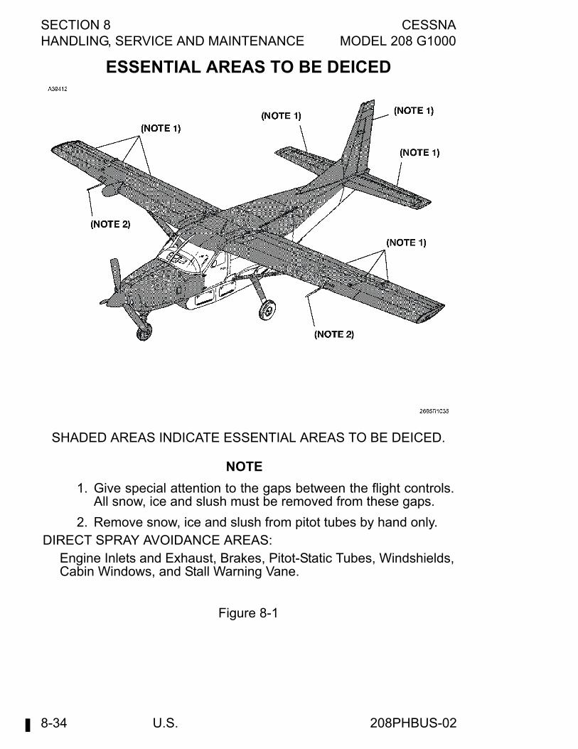
SECTION 8 CESSNAHANDLING, SERVICE AND MAINTENANCE MODEL 208 G1000
U.S.8-34
ESSENTIAL AREAS TO BE DEICED
SHADED AREAS INDICATE ESSENTIAL AREAS TO BE DEICED.
NOTE
1. Give special attention to the gaps between the flight controls.All snow, ice and slush must be removed from these gaps.
2. Remove snow, ice and slush from pitot tubes by hand only.DIRECT SPRAY AVOIDANCE AREAS:
Engine Inlets and Exhaust, Brakes, Pitot-Static Tubes, Windshields,Cabin Windows, and Stall Warning Vane.
Figure 8-1
208PHBUS-02
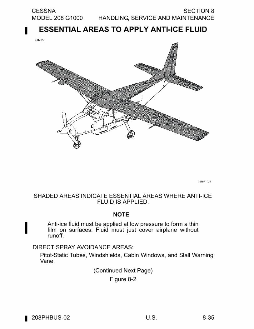
CESSNA SECTION 8MODEL 208 G1000 HANDLING, SERVICE AND MAINTENANCE
U.S. 8-35
ESSENTIAL AREAS TO APPLY ANTI-ICE FLUID
SHADED AREAS INDICATE ESSENTIAL AREAS WHERE ANTI-ICE FLUID IS APPLIED.
NOTE
Anti-ice fluid must be applied at low pressure to form a thinfilm on surfaces. Fluid must just cover airplane withoutrunoff.
DIRECT SPRAY AVOIDANCE AREAS:Pitot-Static Tubes, Windshields, Cabin Windows, and Stall WarningVane.
(Continued Next Page)
Figure 8-2
208PHBUS-02
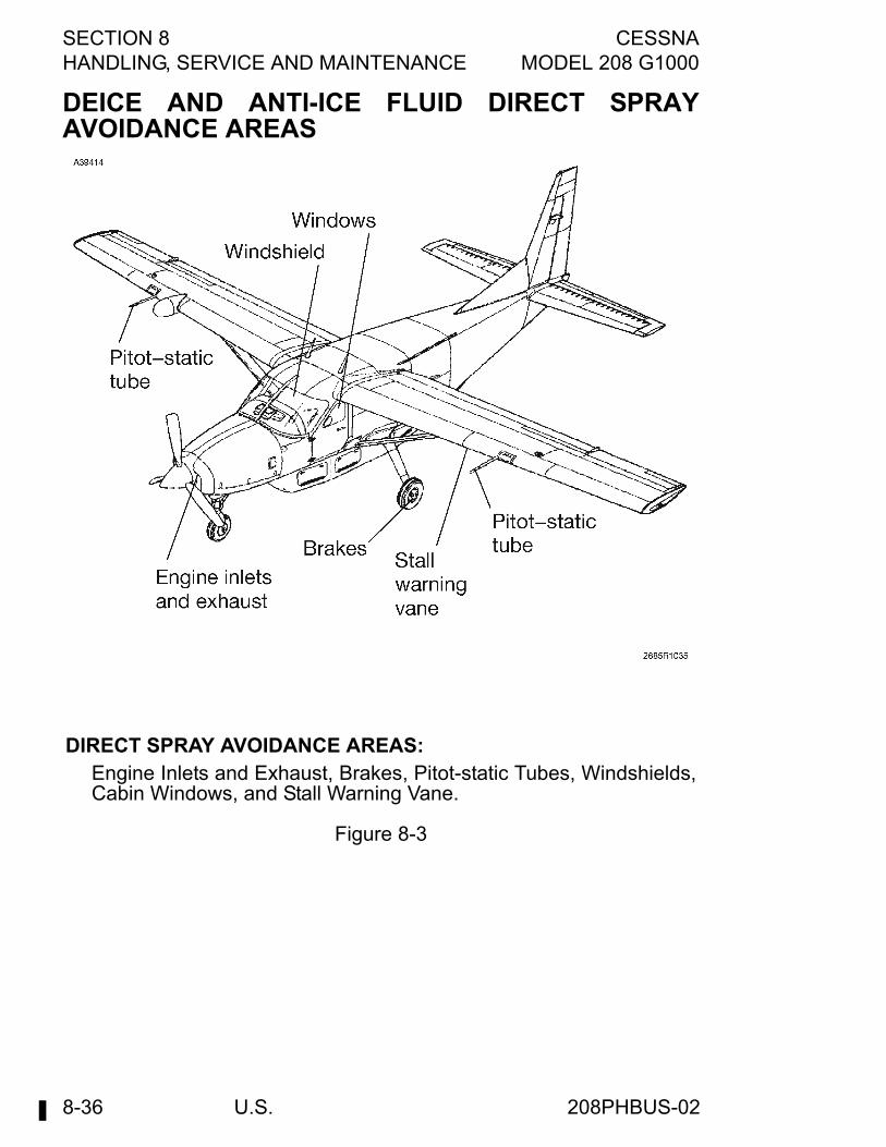
SECTION 8 CESSNAHANDLING, SERVICE AND MAINTENANCE MODEL 208 G1000
U.S.8-36
DEICE AND ANTI-ICE FLUID DIRECT SPRAYAVOIDANCE AREAS
DIRECT SPRAY AVOIDANCE AREAS:Engine Inlets and Exhaust, Brakes, Pitot-static Tubes, Windshields,Cabin Windows, and Stall Warning Vane.
Figure 8-3
208PHBUS-02
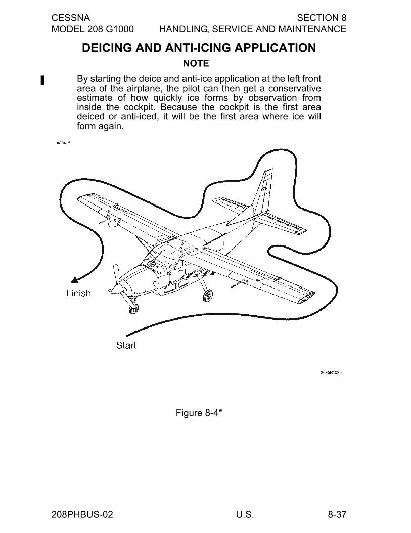
CESSNA SECTION 8MODEL 208 G1000 HANDLING, SERVICE AND MAINTENANCE
U.S. 8-37
DEICING AND ANTI-ICING APPLICATION NOTE
By starting the deice and anti-ice application at the left frontarea of the airplane, the pilot can then get a conservativeestimate of how quickly ice forms by observation frominside the cockpit. Because the cockpit is the first areadeiced or anti-iced, it will be the first area where ice willform again.
Figure 8-4*
208PHBUS-02
SECTION 8 CESSNAHANDLING, SERVICE AND MAINTENANCE MODEL 208 G1000
U.S.8-38
CLEANING AND CARE
WINDSHIELD AND WINDOWSThe windshield and windows are constructed of cast acrylic. Thesurface hardness of acrylic is approximately equal to that of copper orbrass. Do not use a canvas cover on the windshield unless freezingrain or sleet is anticipated. Canvas covers may scratch the plasticsurface. When cleaning and waxing the windshield and windows, useonly the following prescribed methods and materials.
WINDSHIELD AND WINDOW MAINTENANCEPROCEDURESThe following procedures provide the most current informationregarding cleaning and servicing windshields and windows. Impropercleaning or use of unapproved cleaning agents can cause damage tothese surfaces.
CLEANING INSTRUCTIONS
CAUTION
Windshields and windows can be easily damaged byimproper handling and cleaning techniques.
1. Place airplane inside hangar or in shaded area and allow to coolfrom heat of sun's direct rays.
2. Using clean (preferably running) water, flood the surface. Usebare hands with no jewelry to feel and dislodge any dirt orabrasive materials.
3. Using a mild soap or detergent (such as a dishwashing liquid) inwater, wash the surface. Again, use only the bare hand to providerubbing force. (A clean cloth may be used to transfer the soapsolution to the surface, but extreme care must be exercised toprevent scratching the surface.)
(Continued Next Page)
208PHBUS-00
CESSNA SECTION 8MODEL 208 G1000 HANDLING, SERVICE AND MAINTENANCE
U.S. 8-39
CLEANING INSTRUCTIONS (Continued)4. On acrylic windshields and windows, if soils which cannot be
removed by a mild detergent, Type II aliphatic naphtha appliedwith a soft clean cloth may be used as a cleaning solvent. Be sureto frequently refold the cloth to avoid redepositing soil and/orscratching the windshield and windows with any abrasiveparticles.
5. Rinse surface thoroughly with clean fresh water and dry with aclean cloth.
CAUTION
Do not use any of the following on, or for cleaning,windshields and windows: methanol, denaturedalcohol, gasoline, benzene, xylene, MEK, acetone,carbon tetrachloride, lacquer thinners, commercial orhousehold window cleaning sprays. When in doubtabout any product, do not use it.
6. Hard polishing wax should be applied to acrylic surfaces. (Thewax has an index of refraction nearly the same as transparentacrylic and will tend to mask any shallow scratches).
7. Acrylic surfaces may be polished using a polish meeting FederalSpecification P-P-560 applied per the manufacturer’sinstructions.
CAUTION
On acrylic surfaces, use only rain repellents thatconform to specification MIL-W-6882. Refer to theMaterials For Acrylic Windshields and Windows chartfor specific rain repellent products approved by Cessna.
NOTE
When applying or removing wax or polish, use a clean softcloth.
8. Windshields may have rain repellent applied per themanufacturer’s instructions. Caution must be used not to get rainrepellent on painted surfaces surrounding the windshield.
208PHBUS-00
SECTION 8 CESSNAHANDLING, SERVICE AND MAINTENANCE MODEL 208 G1000
U.S.8-40
WINDSHIELD AND WINDOW PREVENTIVEMAINTENANCE
CAUTION
Utilization of the following techniques will help minimizewindshield and window crazing.
1. Keep all surfaces of windshields and windows clean.2. If desired, wax acrylic surfaces.3. Carefully cover all surfaces during any painting, powerplant
cleaning or other procedure that calls for the use of any type ofsolvents or chemicals. The following coatings are approved foruse in protecting surfaces from solvent attack:a. White Spray Lab, MIL-C-6799, Type I, Class II.b. WPL-3 Masking Paper - St. Regis, Newton, MA.c. 5 X N - Poly-Spotstick - St. Regis, Newton, MA.d. Protex 40 - Mask Off Company, Monrovia, CA and
Southwest Paper Co., Wichita, KS.e. Protex 10VS - Mask Off Company, Monrovia, CA and
Southwest Paper Co., Wichita, KSf. Scotch 344 Black Tape - 3M Company
4. Do not park or store the airplane where it might be subjected todirect contact with or vapors from: methanol, denatured alcohol,gasoline, benzene, xylene, MEK, acetone, carbon tetrachloride,lacquer thinners, commercial or household window cleaningsprays, paint strippers, or other types of solvents.
5. Do not use solar screens or shields installed on inside of airplaneor leave sunvisors up against windshield. The reflected heat fromthese items causes elevated temperatures which acceleratecrazing.
6. Do not use power drill motor or powered device to clean, polish,or wax surfaces.
208PHBUS-00
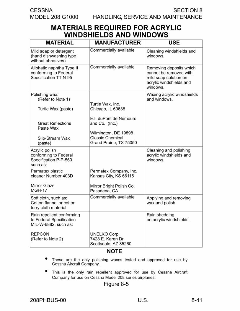
CESSNA SECTION 8MODEL 208 G1000 HANDLING, SERVICE AND MAINTENANCE
U.S. 8-41
MATERIALS REQUIRED FOR ACRYLIC WINDSHIELDS AND WINDOWS
MATERIAL MANUFACTURER USE
Mild soap or detergent(hand dishwashing typewithout abrasives)
Commercially available Cleaning windshields and windows.
Aliphatic naphtha Type IIconforming to FederalSpecification TT-N-95
Commercially available Removing deposits whichcannot be removed withmild soap solution onacrylic windshields andwindows.
Polishing wax:(Refer to Note 1)
Turtle Wax (paste)
Great ReflectionsPaste Wax
Slip-Stream Wax(paste)
Turtle Wax, Inc.Chicago, IL 60638
E.I. duPont de Nemoursand Co., (Inc.)
Wilmington, DE 19898Classic ChemicalGrand Prairie, TX 75050
Waxing acrylic windshieldsand windows.
Acrylic polishconforming to FederalSpecification P-P-560such as:
Permatex plasticcleaner Number 403D
Mirror GlazeMGH-17
Permatex Company, Inc.Kansas City, KS 66115
Mirror Bright Polish Co.Pasadena, CA
Cleaning and polishingacrylic windshields andwindows.
Soft cloth, such as:Cotton flannel or cottonterry cloth material
Commercially available Applying and removingwax and polish.
Rain repellent conformingto Federal SpecificationMIL-W-6882, such as:
REPCON(Refer to Note 2)
UNELKO Corp.7428 E. Karen Dr.Scottsdale, AZ 85260
Rain sheddingon acrylic windshields.
NOTE
• These are the only polishing waxes tested and approved for use byCessna Aircraft Company.
• This is the only rain repellent approved for use by Cessna AircraftCompany for use on Cessna Model 208 series airplanes.
Figure 8-5
208PHBUS-00
SECTION 8 CESSNAHANDLING, SERVICE AND MAINTENANCE MODEL 208 G1000
U.S.8-42
PAINTED SURFACESThe painted exterior surfaces of the Cessna 208B have a durable, long-lasting finish. Approximately 10 days are required for the paint to curecompletely; in most cases, the curing period will have been completedprior to delivery of the airplane. In the event that polishing or buffing isrequired within the curing period, it is recommended that the work bedone by someone experienced in handling uncured paint. Any CessnaService Station can accomplish this work.Generally, the painted surfaces can be kept bright by washing withwater and mild soap, followed by a rinse with water and drying withcloths or a chamois. Harsh or abrasive soaps or detergents that causecorrosion or scratches must never be used. Remove stubborn oil andgrease with a cloth moistened with Stoddard solvent.To seal any minor surface chips or scratches and protect againstcorrosion, the airplane must be waxed regularly with a good automotivewax applied in accordance with the manufacturer's instructions. If theairplane is operated in a sea coast or other salt water environment, itmust be washed and waxed more frequently to assure adequateprotection. Special care must be taken to seal around rivet heads andskin laps, which are the areas most susceptible to corrosion. A heaviercoating of wax on the leading edges of the wings and tail and on thecowl nose cap and propeller spinner will help reduce the abrasionencountered in these areas. Re application of wax will generally benecessary after cleaning with soap solutions or after chemical deicingoperations.When the airplane is parked outside in cold climates and it is necessaryto remove ice before flight, care must be taken to protect the paintedsurfaces during ice removal with chemical liquids. Isopropyl alcohol willsatisfactorily remove ice accumulations without damaging the paint.However, keep the isopropyl alcohol away from the windshield andcabin windows since it will attack the plastic and may cause it to craze.
208PHBUS-00
CESSNA SECTION 8MODEL 208 G1000 HANDLING, SERVICE AND MAINTENANCE
U.S. 8-43
STABILIZER ABRASION BOOT CAREIf the airplane is equipped with stabilizer abrasion boots, keep themclean and free from oil and grease, which can swell the rubber. Washthem with mild soap and water, using Form Tech AC cleaner or naphthato remove stubborn grease. Do not scrub the boots and be sure to wipeoff all solvent before it dries. Boots with loosened edges or small tearsmust be repaired. Your Cessna Service Station has the proper materialand knowledge how to do this correctly.
PROPELLER CAREAlways conduct a preflight inspection and occasionally wipe the bladeswith a cloth dampened with oil to clean off grass and bug stains,minimize corrosion, and assure a longer blade life. Waxing the bladeswith an automotive type paste wax on a regular basis will furtherminimize corrosion. Damaged or blistered paint must be repainted.During the preflight inspection, check the blades for nicks, gouges,scratches, corrosion pits, etc., the anti-ice boots for security, thepropeller hub for evidence of grease and oil leaks, and the propellerspinner for condition and security. Repair of small nicks and scratchesmay be performed by qualified mechanics in accordance withprocedures specified in FAA Advisory Circular 43.13-1A. However,whenever a significant amount of metal is removed, or in the case ofpreviously reworked blades that may be at or near minimum width andthickness limits, the appropriate McCauley Service Manual must beconsulted to determine if minimum allowable blade width and thicknesslimits have been exceeded. If these limits are exceeded, bladereplacement is required. After filing and polishing, the damaged areamust be inspected by the dye penetrant method to verify that alldamage has been removed and the blade is not cracked. The areashould then be reprotected by localized application of chemical film perMIL-C-5541 (e.g., Alodine) and repainted as necessary. Large nicks orscratches or other damage involving such things as bent blades,balance, diameter reduction, etc. must be corrected by an FAAapproved propeller repair station.
208PHBUS-00
SECTION 8 CESSNAHANDLING, SERVICE AND MAINTENANCE MODEL 208 G1000
U.S.8-44
ENGINE CARE
ENGINE EXTERIOR/COMPARTMENT CLEANINGThe engine exterior and compartment may be cleaned using a suitablesolvent. Most efficient cleaning is done using a spray-type cleaner.Before spray cleaning, make sure that protection is afforded forcomponents that might be adversely affected by the solvent. Refer tothe Maintenance Manual for proper lubrication of controls andcomponents after engine cleaning.The benefits of performance improvements and increased service lifeof hot section parts accruing from instituting a regular compressor washprogram cannot be overemphasized. A compressor wash ring isinstalled on the top of the engine adjacent to the induction air inletscreen to facilitate this maintenance program.Compressor washes can be performed by either motoring the enginewith the starter or running the engine. Depending on the nature of theoperating environment and the type of deposits in the engine gas path,either of the two wash methods can be used to remove salt or dirt andother baked-on deposits that accumulate over a period of time andcause engine performance deterioration. When the wash is performedsolely to remove salt deposits, it is known as a “desalination” wash. Awash performed to remove baked on deposits to improve engineperformance is known as a performance recovery wash. A motoringwash is conducted at a gas generator RPM of 14-25%; the runningwash is carried out at an Ng of approximately 60% (23,000 RPM). Thewater or cleaning mixture and rinsing solution, dependent on ambienttemperature, is injected at different pressure, depending on the washmethod being conducted.Operating environment determines the nature of the wash, thefrequency, and wash method recommended. If operating in acontinuously salt-laden environment, a desalination wash isrecommended following the last flight of the day by means of themotoring method. Occasionally, salt-laden environments maynecessitate a desalination wash each week using the motoring method.Less severe and more general operating environments are not asconducive to rapid deposit buildup but eventually can contribute toperformance deterioration and necessitate a performance recoverywash at intervals of 100-200 hours. In these general environments, amotoring wash is recommended for light soil and multiple motoring or arunning wash is suggested for heavy soil.
CAUTION
Always observe engine starting cycle limits whenconducting motoring wash procedures.
208PHBUS-00
CESSNA SECTION 8MODEL 208 G1000 HANDLING, SERVICE AND MAINTENANCE
U.S. 8-45
ENGINE COMPRESSOR WASHA number of cleaning agents are recommended for addition to water toform the cleaning solution used for compressor wash. However, themixture proportion of all the cleaning agents is not identical. Dependingon the prevalent ambient temperature, aviation kerosene and methanolmust be added to the cleaning solution in various proportions. Thequality of the water used is also important; any drinking quality water ispermissible for a motoring wash, but demineralized water only isrecommended for a running wash. Detailed information concerning thecleaning mixture components, mixture formulation, recommendedquantity and application equipment can be found in Pratt & WhitneyAircraft Gas Turbine Operation Information Letter No. 7.
COMPRESSOR TURBINE BLADE WASHPratt & Whitney Canada has developed a procedure for performing acompressor turbine blade motoring wash. This technique will facilitatethe removal of contaminants from the compressor turbine blade airfoilsurfaces, thereby minimizing sulphidation attack of these surfaces. Thisserves as an aid for obtaining optimum blade service life. With thismethod, a water or water/methanol solution is injected directly into thecombustion chamber by way of a special spray tube which is installedin one of the igniter plug ports. This method of engine wash does notreplace the need for a normal engine compressor wash forperformance recovery or desalination purposes.Compressor turbine blade washing is accomplished using water ofdrinking quality (potable) only at ambient temperatures of +2°C (36°F)and above. Use a water/methanol solution at ambient temperaturesbelow +2°C (36°F). Consult the Engine Maintenance Manual forsolution strength according to ambient temperature and review SpecialInstruction P & WC: 4-84 for washing procedures and limitations.
208PHBUS-00
SECTION 8 CESSNAHANDLING, SERVICE AND MAINTENANCE MODEL 208 G1000
U.S.8-46
INTERIOR CAREThe instrument panel, control wheel, and control knobs need only bewiped off with a damp cloth. Oil and grease on the control wheel andcontrol knobs can be removed with a cloth moistened with Stoddardsolvent. Volatile solvents, such as mentioned in paragraphs on care ofthe windshield, must never be used since they soften and craze theplastic.The plastic trim, headliner, door panels, and floor covering in the crewarea of both versions and the rear cabin headliner and sidewalls of thePassenger Version need only be wiped off with a damp cloth. In CargoVersions, the sidewalls, cargo doors, and overhead in the cargo areaare not easily soiled or stained. Dust and loose dirt must be picked upwith a vacuum cleaner. Stubborn dirt can be wiped off with a clothmoistened in clean water. Mild soap suds, used sparingly, will removegrease. The soap must be removed with a clean damp cloth.The protective plywood floor panels (if installed) and aft bulkheadcovering in the cargo area must be vacuum cleaned to remove dustand dirt. A cloth moistened with water will aid in removing heavy soil.Do not use excessive amounts of water, which would deteriorate theprotective floor panels.To remove dust and loose dirt from seating upholstery, clean the seatsregularly with a vacuum cleaner.Blot up any spilled liquid on the seats promptly with cleansing tissue orrags. Do not pat the spot; press the blotting material firmly and hold itfor several seconds. Continue blotting until no more liquid is taken up.Scrape off sticky materials with a dull knife, then spot-clean the area.Oily spots on the seats may be cleaned with household spot removers,used sparingly. Before using any solvent, read the instructions on thecontainer and test it on an obscure place on the fabric to be cleaned.Never saturate the fabric with a volatile solvent; it may damage thepadding and backing materials.Soiled seating upholstery may be cleaned with foam-type detergentused according to the manufacturer’s instructions. To minimize wettingthe fabric, keep the foam as dry as possible and remove it with avacuum cleaner.
208PHBUS-00
CESSNA SECTION 8MODEL 208 G1000 HANDLING, SERVICE AND MAINTENANCE
U.S. 8-47
PROLONGED OUT-OF-SERVICE CAREProlonged out-of-service care applies to all airplanes that will not beflown for an indefinite period (less than 60 days) but which are to bekept ready to fly with the least possible preparation. If the airplane is tobe stored temporarily or indefinitely, refer to the Airplane MaintenanceManual for proper storage procedures. The Maintenance Manualprovides amplification for the following procedures:
1. The procedure to be followed for preservation of an engine inservice depends on the period of inactivity and whether or notthe engine may be rotated during the inactive period. Theexpected period of inactivity must be established and referencemade to the Engine Preservation Schedule. The preservationcarried out must be recorded in the engine maintenance recordand on tags secured to the engine. The following preservationschedule lists procedures to be followed:
CAUTION
Under no circumstances should preservative oil besprayed into the compressor or exhaust ports of theengine. Dirt particles deposited on blades and vanesduring engine operation will adhere and alter the airfoilshape, adversely affecting compressor efficiency.
a. 0 to 7 Days - The engine may be left in an inactive state,with no preservation protection, provided the engine issheltered, humidity is not excessively high, and the engineis not subjected to extreme temperature changes that wouldproduce condensation.
b. 8 to 28 Days - An engine inactive for up to 28 days requiresno preservation provided all engine openings are sealed offand relative humidity in the engine is maintained at less than40%. Humidity control is maintained by placing desiccantbags and a humidity indicator on wooden racks in theengine exhaust duct. Suitable windows must be provided inthe exhaust closure to facilitate observation of the humidityindicators.
(Continued Next Page)
208PHBUS-00
SECTION 8 CESSNAHANDLING, SERVICE AND MAINTENANCE MODEL 208 G1000
U.S.8-48
PROLONGED OUT-OF-SERVICE CARE (Continued)
c. 29 to 90 Days - An engine inactive for a period exceeding 28days, but less than 91 days, need only have the fuel systempreserved, engine openings covered, and desiccant bagsand humidity indicators installed.
d. 91 Days and Over - An engine inactive over 90 days in theairframe or removed for long-term storage in a container,must, in addition to the 29 to 90 day procedure, have theengine oil drained and unused accessory drive padssprayed.
2. Place a cover over the pitot tube and install the two engine inletcovers. To prevent the propeller from windmilling, install thepropeller anchor over a blade of the propeller and secure thestrap around the nose gear or to the bracket located on thelower right hand cowl. Cover all other openings to prevent entryof foreign objects.
3. Keep the fuel tanks full to minimize condensation in the tanks.4. If the airplane will be out of service for 5 days or more,
disconnect the battery. If the battery is left in the airplane, it mustbe removed and serviced regularly to prevent discharge. If thebattery is removed from the airplane, check it regularly for stateof charge.
5. If the airplane is stored outside, tie-down the airplane inaccordance with the procedure in this section. Chock the noseand main wheels; do not set the parking brake if a long period ofinactivity is anticipated as brake seizing can result.
6. Every two weeks, move the airplane to prevent flat areas on thetires. Mark the tires with tape to ensure the tires are placedapproximately 90° from their previous position.
7. Drain all fuel drain points every 30 days and check for wateraccumulation. Prolonged storage of the airplane will result in awater buildup in the fuel which "leaches out" the fuel additive. Anindication of this is when an excessive amount of wateraccumulates at the fuel drain points. Refer to Fuel Additive inthis section for minimum allowable additive concentrations.
BULB REPLACEMENT DURING FLIGHTThe Bulb Replacement figure provides instructions to aid the pilot toreplace annunciator panel light bulbs without tools during flight. It issuggested that spare bulbs be stored in the map compartment.However, if a spare bulb is not available, an identical bulb, which isavailable from other lights listed herein can be substituted for thedefective bulb. For a listing of other bulb requirements and specifictools needed, refer to the Maintenance Manual for this airplane.
208PHBUS-00
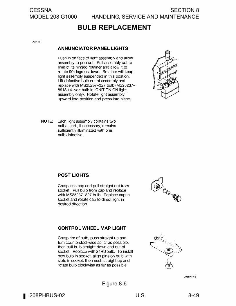
CESSNA SECTION 8MODEL 208 G1000 HANDLING, SERVICE AND MAINTENANCE
U.S. 8-49
BULB REPLACEMENT
Figure 8-6
208PHBUS-02

SECTION 8 CESSNAHANDLING, SERVICE AND MAINTENANCE MODEL 208 G1000
U.S.8-50
This Page Intentionally Left Blank
208PHBUS-02
CESSNA SECTION 9MODEL 208 G1000 SUPPLEMENTS
9-1
SUPPLEMENTS
INTRODUCTION
This section consists of a series of supplements, each covering a singlesystem which may be installed in the airplane. Each supplementcontains a brief description, and when applicable, Limitations,Emergency Procedures, Normal Procedures, and Performance.Operators should refer to each supplement to ensure that all limitationsand procedures appropriate for their airplane are observed.
NOTE
Some supplements contain references to equipmentmanufacturers pilot’s manuals which are supplied with theairplane at the time of delivery from the factory, orwhenever equipment is installed after delivery. Thesemanuals must be kept up-to-date with the latest revisionsissued by the publisher. These vendor manuals contain auser registration form or instructions for obtaining futurerevisions or changes.
WARNING
• Complete familiarity with the airplane and itssystems will not only increase the pilot'sproficiency and ensure optimum operation, butcould provide a basis for analyzing systemmalfunctions in case an emergency isencountered. Information in this section willassist in that familiarization. The responsiblepilot will want to be prepared to make proper andprecise responses in every situation.
• Limitations contained in the followingsupplements are FAA approved. Observance ofthese operating limitations is required by FederalAviation Regulations.
208PHBUS-02

SECTION 9 CESSNASUPPLEMENTS MODEL 208 G1000
9-2
This Page Intentionally Left Blank
208PHBUS-02