Manual Amplifier CLASSIC CA22, CA23, CA31 ... - Audio … · CA22, CA23, CA31, CA41 and CA51 car...
16
How to install and operate the DLS CA22, CA23, CA31, CA41 and CA51 car audio amplifiers. Welcome! This owners manual is written in easy english and uses a lot of drawings to simply the installation and use of the above amplifiers. Your DLS amplifiers must be installed correctly in order to work well. This manual will show you how to install the amplifier like a pro. Please read the entire manual before beginning the installation. Install the amplifier yourself if you feel confident with our instructions and if you have the proper tools. However if you feel unsure, turn over the installa- tion job to someone better suited to it. Warranty Service This amplifier is covered by warranty, depending on the conditions in the country where it is sold. If the amplifier is returned for service, please include the original dated receipt with the product. Technical Assistance For technical assistance ask the shop where the product was sold or the distributor in your very coun- try. You can always phone the DLS Helpdesk in Sweden + 46 31 84 00 60 or send an e-mail to [email protected]. Information can also be found on our WEB-site www.dls.se Contents Features…………………………….. 2 Installation…………………….……. 2 Tools and materials needed………. 3 Amplifier installation kit………….... 3 Routing Wires…………………….... 3 Wiring Power and Outputs……………..…. 4 Inputs and controls………………... 5 Input level control......................... 6 Grand Bass,Crossovers………….... 6 CA 31, CA 41, CA 51 Crossovers… 7 CA 22 and CA 23 speaker wiring: Front speakers…...……………….... 8 Subwoofer…………………………... 8 CA 31 speaker wiring: Front speakers…...……………….... 9 Subwoofer…………………………... 9 CA 41 speaker wiring: Four speakers…………………….... 10 Two speakers + bridged subwoofer. 10 Two way front system with active crossovers……………………. 11 CA 51 speaker wiring: Four speakers…………………….... 12 Subwoofer ...................................... 12 Testing……………………………….. 13 Troubleshooting……………………... 13 Professional tips…………………….. 14 Specifications………………………... 15
Transcript of Manual Amplifier CLASSIC CA22, CA23, CA31 ... - Audio … · CA22, CA23, CA31, CA41 and CA51 car...

How to install and operate the DLSCA22, CA23, CA31, CA41 and CA51car audio amplifiers.
Welcome!This owners manual is written in easy english anduses a lot of drawings to simply the installation anduse of the above amplifiers.
Your DLS amplifiers must be installed correctly inorder to work well. This manual will show you howto install the amplifier like a pro. Please read theentire manual before beginning the installation.Install the amplifier yourself if you feel confident withour instructions and if you have the proper tools.However if you feel unsure, turn over the installa-tion job to someone better suited to it.
Warranty ServiceThis amplifier is covered by warranty, dependingon the conditions in the country where it is sold. Ifthe amplifier is returned for service, please includethe original dated receipt with the product.
Technical Assistance
For technical assistance ask the shop where theproduct was sold or the distributor in your very coun-try.You can always phone the DLS Helpdesk in Sweden+ 46 31 84 00 60 or send an e-mail to [email protected] can also be found on our WEB-sitewww.dls.se
Contents
Features…………………………….. 2Installation…………………….……. 2Tools and materials needed………. 3Amplifier installation kit………….... 3Routing Wires…………………….... 3WiringPower and Outputs……………..…. 4Inputs and controls………………... 5Input level control......................... 6Grand Bass,Crossovers………….... 6CA 31, CA 41, CA 51 Crossovers… 7
CA 22 and CA 23 speaker wiring:Front speakers…...……………….... 8Subwoofer…………………………... 8
CA 31 speaker wiring:Front speakers…...……………….... 9Subwoofer…………………………... 9
CA 41 speaker wiring:Four speakers…………………….... 10Two speakers + bridged subwoofer. 10Two way front system withactive crossovers……………………. 11
CA 51 speaker wiring:Four speakers…………………….... 12Subwoofer...................................... 12
Testing……………………………….. 13Troubleshooting……………………... 13Professional tips…………………….. 14Specifications………………………... 15

All models include
RCA inputsHigh Level inputContinuos variable low pass and/or highpass crossoverBass boost feature (only on CA23 & CA41)Remote turn on / offAutomatic remote turn on/ off on high levelinput without connecting any remote wireElectronic protection circuitry againstshort-circuit, DC offset and thermal overload.Bridgeable design to direct full power toone or two subwoofers etc.
InstallationBefore you begin installation
Before you begin you need to read the manual, to havesome tools, cables and other material available. Thereis one such list of material on the following page.
Amplifier location
Important Allow air circulation around the amplifier.
2
Disconnect Battery
Before starting the instal-lation, always disconnectthe negative terminal ofthe battery.
The DLS Classic series of amplifiers have acompact design that allows great flexibility inmounting. You can mount it under a seat or in thetrunk.When you select a location, do remember that theamplifier generates a lot of heat.
Choose a location where air can circulate freelyaround the amplifier. Do not cover the amplifierwith carpets or hide behind trim panels.Do not mount the amplifier in an inverted or upsidedown position.
Check all locations and placements carefullybefore making any cuts, drilling any holes or ma-king any connections.
This is the best way tomount the amplifier to getthe best cooling.
CA22, 23, 31, 41 & 51
CA222 x 60 Watt RMS / 2 x 100 Watt max in 2 ohm1x 200 Watt RMS bridgedCA232 x 135 Watt RMS / 2 x 200 Watt max in 2 ohm1 x 400 Watt RMS bridgedCA312 x 65 Watt RMS / 2 x 90 Watt max in 2 ohm1 x 170 Watt RMS bridged1 x 170 W RMS on sub channelCA414 x 70 Watt RMS / 4 x 125 Watt max in 2 ohm2 x 200 Watt RMS bridgedCA51 4 x 50 Watt RMS / 4 x 80 Watt max in 2 ohm2 x 150 Watt RMS bridged1 x 170 Watt RMS on sub channel
All above RMS power ratings with 4 ohm loadat 13,8 Volt DC.
DLS logo on amplifier cooling flange
The DLS logo on top of the amplifier is attachedwith two hex. screws. The logo can be removedand twisted 90 or 180 degrees, and then screwedback in wanted position. The logo can be mountedin four different ways to match your installation.

Tools and material needed
Tools:Flat and Phillips screwdriversWire cutterWire stripperElectric drill with drillsCrimping toolDigital multimeter or test lampWire brush, scraper or a pieceof an abrasive sheet to removepaint for a good ground connectionGrease to protect the groundconnection from oxidation
Material:Speaker wire: minimum12 AWG = 4 mm2 for subwoofers13 – 16 AWG = 1,5-2,5 mm2 for otherspeakersSheet metal screws for mounting theamplifier to the amplifier board and theamplifier board to the car + some extrafor fuse holder, amplifier ground etc.Electrical insulation tape½ inch thick plywood or particle board forthe amplifier to be mounted upon.
Amplifier installation kit:If available,buy an amplifier installation kit. Itcontains normally all you need. This is what youhave to buy if you buy the items separately
20- 25 feet = 6- 7.5 meter power cable,minimum AWG 8 = 10 mm2 or heavier1 pc of fuseholder to install close to thecar battery + fuse 50 Ampere.20 feet of AWG 15 = 1,5 mm2 wire forremote turn on / off cable from radio.RCA-cable for input from radio.- 20 feet or 5 meter for trunk installations-12 feet or 2 – 3 meter for under seatinstallationsTwo ring crimp terminals –onefor connection to the battery plus and onefor the amplifier ground connection.Two heavy fork crimp terminals to connect+ and – to amplifer – but you do only needthem if you use heavy cable or to make theinstallation look nicer.Four to ten fork crimp terminals toconnect the speaker cables – but you doonly need them if you use heavy cables orwant the installation to look nicer.One fork crimp terminal to connect theremote wire to the amplifier, but you need itonly to make it look nicer.Four to eight splicers to connect speakercables to high level input cable, if high levelinput is used.Wire tiesInsulating grommet or insulating tube
Routing wires
Stereohead unit
3
Professional Tip:
If amplifier installation kits are available with diffe-rent size of power cable, chose the most heavypower cable to improve sound quality and to allowmore amplifiers to be installed now or later.
If possible buy AWG 4 = PL 21 mm2 cable for bestperformance.These are the minimum sizes we recommend forthe different models:CA22 10 mm2 (7AWG)CA23 16 mm2 (5AWG)CA31 21 mm2 (4AWG)CA41 21 mm2 (4AWG)CA51 21 mm2 (4AWG)This is for cable lengths up to 5 meters.The ground cable must have the same size.
CA22, 23, 31, 41 & 51

WiringPower and Outputs
Ground Terminal ( GND )
Remote terminal ( REM )
Use only one or two 30ampere ATC blade type fuses.CA 51 uses three 30 amperefuses. CA22 uses one 25 Afuse.
4
CA22, 23, 31, 41 & 51
Power+12V REM GND
Power terminal ( +12V)
Connect the fuse holder as close to the vehiclebattery + as possible, using AWG 8 = 10 mm2 orheavier cable. Use ring crimp terminal cable toconnect to battery +. Apply silicon grease to thefuse to prevent corrosion.Use a 50 Amp fuse for allamplifiers except for CA51that requires 80 Amp fuse.
Connect the battery cable by a crimp fork terminal (spade ) to the +12 Volt on the amplifier. If you use aAWG 8 = 10 mm2 or thinner cable, you can dowithout the crimp terminal and put the cable rightinto the connector.Be sure to use a rubber grommet or a plasticinsulating tube where the cable passes the firewallor other places when it can easily be jammed.Use ty-wraps to secure to existing cables in theengine compartment.
DLS
Power+12V REM GND
DLS FH1fuse holder
Connect to a good chassis ground. The groundconnection should be clean, unpainted metal toprovide a good electrical connection. Use a wirebrush, a scraper or a piece of an abrasive sheet toclean the metal. Use a lock washer or two to securecontact. Protect with silicon grease or by paintapplied afterwards.
Power(Green)
Protect(Red)
Power Light / Protect light
The power light (green ) comes on whenthe amplifier is turned on.
The protect light ( red ) comes onwhen the amplifier shuts down fromoverheating, or a short circuit ( spea-ker failure)
Power+12V REM GND
Fuses
For RCA cable signal input:Connect the radio power antenna lead = remoteturn on/off from the car stereo to the amplifierremote connection. This turns on the amplifierwhenever the car stereo is turned on.You can either use the built in remote cable in theRCA cable itself or use a separate cable as seenon page 4.Sometimes a small disturbance may enter theamplifier coming from the remote voltage , throughthe built in remote wire and into the RCA cable.Thus we recommend to use a separate remote wireand run the RCA lead separate from remote wire,power cables and speaker cables.You can either use a crimp fork terminal or insertthe cable directly into the amplifier terminal. If thereis no remote voltage available from the stereo, youmust connect to the ignition key through the radioor any accessories fuse.
For High Level input:We recommend you to connect the remote wire asdescribed above. The amplifier will produce softon / soft off operation this way. You must set the Hilevel/Low level switch to High level position in thiscase.In the case that there is no remote voltage availablefrom the car stereo or you want to simplify the in-stallation, the amplifier can be turned on/ turnedoff by the high level input voltage. This is done whenthe Hi level/Low level switch is set to Hi level posi-tion. There is a small disadvantage that this functiongives soft turn on operation but some pop soundwhen switching off.

ImportantOn CA22 & CA23 use either the low level or highlevel input, do not use both at same time.
Low level inputUse a pair of shielded stereo audio cables with RCAtype jack. Most trunk-mountamplifiers need a 20 feetRCA cable ( appr 5 – 6 me-ters). Most under the seatinstallations require 12 feet( 2 – 3 meters) RCA cables.Avoid placing the RCA cableclose to speaker cables,power cables and remotecontrol cable. Connect to input socket A/B. CA41and CA51 are also equipped with separate inputsfor channel C/D. CA31 & CA 51 has also a separateinput for the mono sub channel.
High Level InputConnect left and right speaker wires coming fromthe car stereo to the high level input as shown. Youmust connect both plus and minus as the inputsare balanced, connecting plus only gives lower leveland bad sound quality. By changing the polarity ofplus and minus, you can change the phase.
CA 22, CA23 & CA31
Hi level inputplug on amp.
CA31On CA31 the high level signal is fed internally tochannel C when using high level input.
Automatic turn on when using high level input.With the Hi/Low input swich set to Hi, the amplifierturns on automatically on high input. You dont needto connect a separate remote wire from your headunit.
Input and controls
Input WiringInputs may be low level from the RCA output of thecar stereo or high level from the car stereo speakeroutput. Low level = RCA is to prefer for the best soundquality.
CA41The CA41 four channel amplifier is connectedlikewise, however we have four channels.You can feed two channels from RCA and twochannels using high level input from rear speakercables.
Hi level input plug on amp for CH A/B.
Hi level input plug on amp for CH C/D.
5
RCA Output
Use RCA Outputs toconnect additionalamplifiers (not available onCA31 & CA51).
Input Output
A A
B B
Parallel input on CA 31, CA41 & CA51
On CA41 the PCD positioninternally connects the A/B and C/D inputs.
On CA31 & CA51 the PC (PE)position internally connects the A/B (C/D) input with the input forchannel C (E).In OFF-position you must use dualsignal cables or Y-splits.
CA51The CA51 five channel amplifier is connectedlikewise, however only Channels A, B, C and D canbe fed with high input. The signal is then connectedinternally to channel E.
High Input(C/D Ch) Violet: C ch.+
Violet/Black: C ch.-Green/Black: D ch.-Green: D ch.+
CA22, 23, 31, 41 & 51
Parallel Input CA31
Off PC
Parallel Input CA41
Off PCD
Parallel Input CA51
Off PE
High Input(A/B Ch) White: A ch.+
White/Black: A ch.-Grey/Black: B ch.-Grey: B ch.+
High Input(C/D Ch) White: A ch.+
White/Black: A ch.-Grey/Black: B ch.-Grey: B ch.+

Crossovers
Input Level control
The input level control, 5V – 0,25 V,matches the output of your radio tothe input of the amplifier. After instal-lation is complete, make sure the in-put of the amplifier is turned down allthe way ( counter-clockwise at 5V ).
All DLS Classic amplifiers include high pass filter( HPF ) and low pass filters ( LPF). On CA23 thehigh pass filter is used as a subsonic filter.All filters are continously variable and all filters canbe switched on and off. CA31 & CA51 also includesa subsonic filter.
The HPF ( high pass filter ) blocks very lowfrequencies from reaching the speakers. It is mostlyused at say 60 Hz to protect small speakers ( like6 inch and smaller ) from deep bass. It can also beused as subsonic filter to take away the verydeepest frequencies from a bass box. The typicalsetting is then around 25 – 40 Hz. In CA23 thehigh pass filter is designed as a subsonic filtervariable from 15 Hz to 150 Hz.The slope of the High pass filter is 12 dB / octave.The filter can be switched off if you want to run theamplifier in full range mode.
High Pass Filter / Subsonic filter
HPF
Off On
50Hz 220Hz
15Hz 500Hz
Low Pass Filter
LPF
Off On
80Hz 200Hz
50Hz 500Hz
The LPF ( low pass filter ) mostly used forsubwoofers. It will allow low frequencies only andblocks higher frequencies.A typical setting is 50 – 80 Hz.The filter can be switched in and out. In the CA23amplifier you can select between two differentslopes, 12 dB/ octave or 24 dB/ octave.Choose the slope and the setting that sounds bestin your car.
LPF
Off 24 dB
80Hz 200Hz
50Hz 500Hz
12dB
CA22 CA23
6
CA22 CA23
Subsonic
Off On
40Hz 100Hz
15Hz 150Hz
To ensure best possible performance from theamplifiers a switch is installed to select between Hiand Low input.When using High Level input:Push in the button to position”Hi Level”When using Low level input:Push out the button to position”Low Level”
If the switch is set to wrong position, the amplifierstill works, but the risk for disturbances or distortionincreases.
Hi / Low level input switch
CA22, 23, 31, 41 & 51
Hi levelLow level
Play a tape or CD, make sure all bass or treblesettings or equalizer are flat, and turn the volumeof the radio up until you just start to hear distortion.Turn the volume control down just a bit. On theamplifier increase the input level control ( clockwiseor to the right ) until you just start to hear distortion,then back the level control just a bit. Now your ra-dio and amplifier levels are matched.
Grand bass on CA23 & CA41
Grand Bass is used to increase the bass volumeat an interval of bass frequencies. You can selectthe center frequency between 25Hz and 80 Hzand the amplification between 0 dB ( noamplification ) and 18 dB ( full amplification ).The slope of the filter is 10 – 12 dB at maximumsetting.This function is used to compensate for the bassbox function and to adjust for your own taste ofbass. Set level control at 0 dB if you want it to beinoperative.
The phase control on CA31 & CA51 can be setcontinuously from 0 - 180 degrees. This is veryuseful when you want to adjust the bass sound forbest front stage image. Start on 0 and turn thecontrol slowly clockwise until you experience thatthe bass sound is coming from the front. If you dontget the result you want, also try tophase reverse the subwooferconnections and makea new adjustment.
Phase control CA31 & CA51
0 180
PHASE
Subsonic filter CA31 & CA51
The Subsonic filter blocks the verydeepest frequencies from reaching thesubwoofers. It has a fixed frequencyof 25 Hz and can be switched On / Off.For sub channels C (CA31) and E(CA51) only.
Subsonic
Off On
Level
5V 0,25V
Grand Bass
40Hz 60Hz
25Hz 80Hz 0dB 18dB

The CA41 is a four channel amplifier. It is mostlyused with a front system connected to channels C/D and a subwoofer connected to channel A/B. Youwill find speaker wiring and filter setting example onpage 10. Please observe the proper settings of thechannel A/B LPF multiplier switch and of the channelC/D HPF multiplier switch.The CA41 can also be used to feed a 2–way frontsystem with active crossovers between midbassesand tweeters. This is described in a speaker wiringand filter setting example on page 11.
Channel A/B is equipped very much like the CA22and CA23, however the LPF has a multiplier. Thusthe frequency range of the LPF can be varied from50 Hz – 500 Hz in the x1 position or 500 Hz – 5 kHzin the x10 position. This way we can use thisamplifier to feed a 2-way system, where themidbasses are feed from 80 Hz – 4 kHz.The tweeters connected to channel C/D , operatefrom 4 kHz upwards using the HPF in multiplier po-sition x 10 150 Hz – 5 kHz.
7
The CA51 is a five channel amplifier. On channelA/B, C/D the filter configuration is exactly the sameas for CA41.Channel E is a subwoofer mono channel with alowpass filter adjustable from 60 to 120 Hz. ChannelE has also a subsonic filter that can be switched IN-OUT. The subsonic filter has a fixed frequency of25 Hz. The CA51 has also a phase control variablefrom 0 - 180 degrees.
CA22, 23, 31, 41 & 51
Multiply
x1 x10
80/800Hz
Off On
200/2(k)Hz
50/500Hz 500/5(k)Hz
LPF
HPF50/500Hz 220/2(k)Hz
15/150Hz 500/5(k)HzOff On
Multiply
x1 x10
The CA31 is a three channel amplifier. It has avariable high pass filter, 50-150 Hz, for channel A/B. The C channel is for subwoofers and has asubsonic filter, a variable low pass filter, 50-120 Hz,and a phase control variable from 0 - 180 degrees.The subsonic filter can be switched IN-OUT and hasa fixed frequency of 25 Hz.
Crossovers of CA31, CA41 & CA51
CA-51

Two fullrange speakers to CA22 or CA23
LPF
Off On
80Hz 200Hz
50Hz 500Hz
CA22 CA23
LPF
Off 24 dB
80Hz 200Hz
50Hz 500Hz
12dB
With the HPF-filter in OFF position the amplifierallows the speakers to play fullrange. If you forsome reason want to limit the low bassreproduction switch on the HPF-filter. The typicalsetting is then around 25 – 40 Hz.
The LPF-filter should be OFF.
One subwoofer connected in bridge mode toCA22 or CA23
The HPF filter is here used as subsonic filter to takeaway the very deepest frequencies. The typical set-ting is around 25 – 40 Hz.
CA22 CA23
The LPF will allow low frequencies only and blockshigher frequencies. A typical setting is 70 – 90 Hz.In the CA23 amplifier you can select between twodifferent slopes, 12 dB/ octave or 24 dB/ octave.Choose the slope and the setting that sounds bestin your car.
LPF
Off On
80Hz 200Hz
50Hz 500Hz
LPF
Off 24 dB
80Hz 200Hz
50Hz 500Hz
12dB
Filter settings
NOTE!4 ohm minimum load when using bridge modeconnection. Lower impedances may damage theamplifier. In bridge mode the amplifier sees a 4ohm load as 2 ohm.
Filter settings
8
CA22, 23
Speaker wiring CA 22 & CA23
HPF
Off On
50Hz 220Hz
15Hz 500Hz
Subsonic
Off On
40Hz 100Hz
15Hz 150Hz
CA22 CA23HPF
Off On
50Hz 220Hz
15Hz 500Hz
Subsonic
Off On
40Hz 100Hz
15Hz 150Hz
CA22 CA23
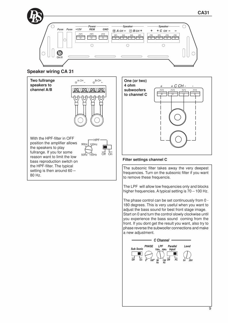
CA31
Speaker wiring CA 31
Two fullrangespeakers tochannel A/B
HPFWith the HPF-filter in OFFposition the amplifier allowsthe speakers to playfullrange. If you for somereason want to limit the lowbass reproduction switch onthe HPF-filter. The typicalsetting is then around 60 –80 Hz.
One (or two)4 ohmsubwoofersto channel C
Filter settings channel C
+ + C CH - -
The subsonic filter takes away the very deepestfrequencies. Turn on the subsonic filter if you wantto remove these frequencis.
The LPF will allow low frequencies only and blockshigher frequencies. A typical setting is 70 – 100 Hz.
The phase control can be set continuously from 0 -180 degrees. This is very useful when you want toadjust the bass sound for best front stage image.Start on 0 and turn the control slowly clockwise untilyou experience the bass sound coming from thefront. If you dont get the result you want, also try tophase reverse the subwoofer connections and makea new adjustment.
50Hz 150Hz Off On
120Hz90Hz
9
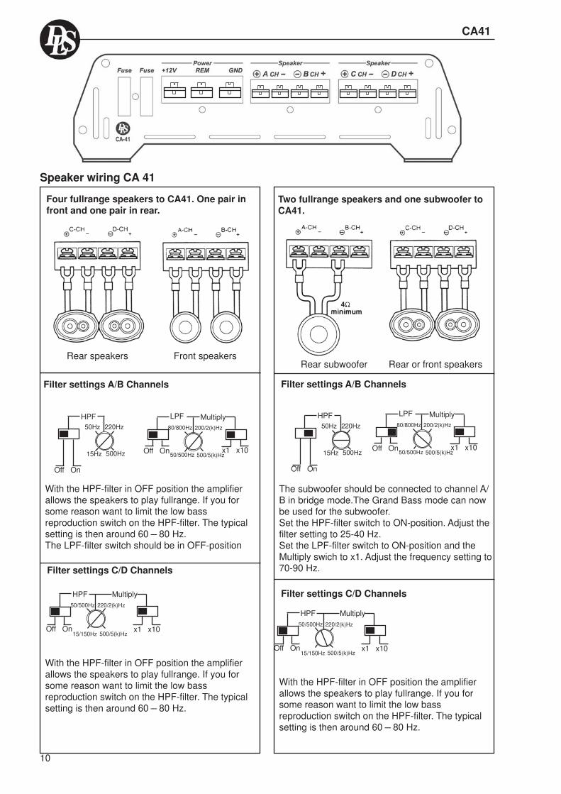
10
Two fullrange speakers and one subwoofer toCA41.
Rear subwoofer Rear or front speakers
Filter settings A/B Channels
The subwoofer should be connected to channel A/B in bridge mode.The Grand Bass mode can nowbe used for the subwoofer.Set the HPF-filter switch to ON-position. Adjust thefilter setting to 25-40 Hz.Set the LPF-filter switch to ON-position and theMultiply swich to x1. Adjust the frequency setting to70-90 Hz.
Filter settings C/D Channels
With the HPF-filter in OFF position the amplifierallows the speakers to play fullrange. If you forsome reason want to limit the low bassreproduction switch on the HPF-filter. The typicalsetting is then around 60 – 80 Hz.
HPF
Off On
50Hz 220Hz
15Hz 500Hz
Multiply
x1 x10
80/800Hz
Off On
200/2(k)Hz
50/500Hz 500/5(k)Hz
LPF
220/2(k)Hz
CA41
Speaker wiring CA 41
Four fullrange speakers to CA41. One pair infront and one pair in rear.
Rear speakers Front speakers
Filter settings A/B Channels
With the HPF-filter in OFF position the amplifierallows the speakers to play fullrange. If you forsome reason want to limit the low bassreproduction switch on the HPF-filter. The typicalsetting is then around 60 – 80 Hz.The LPF-filter switch should be in OFF-position
Multiply
x1 x10
80/800Hz
Off On
200/2(k)Hz
50/500Hz 500/5(k)Hz
LPF
HPF50/500Hz 220/2(k)Hz
15/150Hz 500/5(k)HzOff On
Multiply
x1 x10
HPF
Off On
50Hz 220Hz
15Hz 500Hz
Filter settings C/D Channels
With the HPF-filter in OFF position the amplifierallows the speakers to play fullrange. If you forsome reason want to limit the low bassreproduction switch on the HPF-filter. The typicalsetting is then around 60 – 80 Hz.
HPF50/500Hz
15/150Hz 500/5(k)HzOff On
Multiply
x1 x10

One 2-way speaker system to CA41 usingactive crossover between tweeter andmidrange
Midrange Tweeters
C D
Multiply
x1 x10
80/800Hz
Off On
200/2(k)Hz
50/500Hz 500/5(k)Hz
LPFHPF
Off On
50Hz 220Hz
15Hz 500Hz
Filter settings A/B Channels
Filter settings C/D Channels
We want a crossover point of 4 kHz between tweeterand midrange. If you for some reason want to limitthe low bass reproduction switch on the HPF-filter.The typical setting is then around 60 – 80 Hz. Switchthe LPF-filter switch to ON and the Multiply switchto x10 position. Now you can adjust the filter settingfrom 500 Hz to 5 kHz. Adjust the setting to 4 kHz.
Channel C/D are used for tweeters and must beset to play from 4 kHz and up. The HPF-filter switchmust be ON and the multiply swich in x 10 position.Now you can adjust the filter setting from 150Hz to5 kHz. Adjust the setting to 4 kHz.
11
CA41
Speaker wiring CA 41
HPF50/500Hz 220/2(k)Hz
15/150Hz 500/5(k)HzOff On
Multiply
x1 x10

CA51
Speaker wiring CA 51
Four fullrange speakers to CA51. One pair infront and one pair in rear.
Rear speakers Front speakers
Filter settings A/B Channels
With the HPF-filter in OFF position the amplifierallows the speakers to play fullrange. If you forsome reason want to limit the low bassreproduction switch on the HPF-filter. The typicalsetting is then around 60 – 80 Hz.The LPF-filter switch should be in OFF-position
Multiply
x1 x10
80/800Hz
Off On
200/2(k)Hz
50/500Hz 500/5(k)Hz
LPF
HPF50/500Hz 220/2(k)Hz
15/150Hz 500/5(k)HzOff On
Multiply
x1 x10
HPF
Off On
50Hz 220Hz
15Hz 500Hz
Filter settings C/D Channels
LPF
Off On
80Hz 200Hz
50Hz 500Hz
With the HPF-filter in OFF position the amplifierallows the speakers to play fullrange. If you forsome reason want to limit the low bassreproduction switch on the HPF-filter. The typicalsetting is then around 25 – 40 Hz.The LPF-filter switch should be in OFF-position
Subwoofer to CA51The CA51 is a five channel amplifier. On channelsA/B, C/D the filter configuration is exactly the sameas for CA41. For speaker connections on thesechannels you can use the examples for CA41.Channel E is a subwoofer mono channel with alowpass filter adjustable from 50 to 500 Hz. ChannelE has also a subsonic filter that can be switchedIN-OUT. The subsonic filter has a fixed frequencyof 25 Hz.You can connect one 4 ohm subwoofer to channelE.
Filter settings E Channel
The subsonic filter takes away the very deepestfrequencies. Turn on the subsonic filter if you wantto remove these frequencis.
The LPF will allow low frequencies only and blockshigher frequencies. A typical setting is 70 – 100 Hz.
The phase control can be set continuously from 0 -180 degrees. This is very useful when you want toadjust the bass sound for best front stage image.Start on 0 and turn the control slowly clockwise untilyou experience the bass sound coming from thefront. If you dont getthe result you want,also try to phase reversethe subwooferconnections and makea new adjustment.
12

13
TestingBefore you finish the installation, you should do thefollowing tests to make sure the wiring is correct andeverything is operating properly.
Reconnect Battery
When wiring is complete,reconnect the batterynegative terminal.
If problems occour during the installation, or later,this guide might help you to find out whats´s wrong.
THE AMPLIFIER IS DEAD:1. Check power lead, ground and remote connections at the amplifier using a multi meter.2. Check the battery terminal connections.3. Check the power lead fuse or circuit breaker. If fuse damage continues, inspect the power lead for short circuits.4. Check the amplifier protection fuses. Are these broken change to new ones with the same value. If short circuiting continues, contact your local DLS dealer. A fault may exist in the amplifier.5. To start the amplifier requires a remote voltage of 9-15 volt. Check the voltage with a multi meter.
AMPLIFIER PROTECTION FUSE BLOWS AT LOWVOLUME :1. One or more speaker cables are shorted. Make aninsulation test with a multi meter. The cables must nothave a connection to earth.
THE AMPLIFIER TURNS OFF AFTER 10 - 30 MINU-TES.The amplifier is overheating due to inadequate venti-lation. Check mounting position is free from obstruction.
Do this:1. Move the amplifier to a place with better ventil-
ation.2. Install one or two fans to cool down the heat-
sink.3. Overheating can also be caused by an
impedance load below the level permitted.
NO OUTPUT FROM ONE OR MORE SPEAKERS:
Check the following:1. Balance control position.2. Fader control position.3. Speaker cable connections to both amplifier and
drivers.4. Signal lead plugs and cables.5. Change left and right signal lead plugs in the
amplifier to see if the problem moves to a diffe-rent speaker, the lead has a fault.If the problem remains, the speaker or amplifierare at fault.
Troubleshooting
Test speaker connectionsMake sure the speakers are connected right. Usethe balance control on the head unit to make sureright channel is on right speaker etc. If speakersdon´t play at all, one or both speaker wires maybe disconnected.
Test power wiring
1. Turn on the head unit but do not turn up thevolume. The amplifier power light shouldcome on. If not, check the remote and +12volt wires. Also check the groundconnection.
2. Turn up the head units volume slightly. Allspeakers should operate. if not, check wiringconnections at amplifier and speakers.
CA22, 23, 31, 41 & 51

NOISE PROBLEMS
WHINING NOISE VARYING WITH ENGINEREVOLUTIONS:
Do this:1. Rewire the power supply (12 V) to source
unit direct from battery.2. Rewire ground wire from source unit to
clean position on chassis.3. Check all power connections to ensure that
they are clean and tight.4. Check quality of system ground connection.5. Install a Power Cap capacitor. This can be
helpful against most noise problems.
CONSTANT WHINING NOISE:
Do this:1. Ensure that all equipment has a common
ground point.2. Check quality of earth strap connection from
battery negative terminal to chassis.3. Disconnect signal cables from amplifier to
see if noise disappears. If so the leads arepicking up noise. Test this by laying a newcable over the seats and reconnecting to theamplifier. If the noise does not return, re-route original cable away from source ofinterference.If noise remains regardless of cable position,try to use so called Quasi-balanced signalcables. DLS PRO-cables areQuasibalanced.
SPEAKER POLARITY CHECK.
All speakers in a car audio system should beconnected in phase (the same polarity). All spea-ker cones must move in the same direction. Out ofphase speakers will cause a lack of bass, and apoor stereo soundstage.
Checking polarity:Hold the - connection of the speaker wire to the -terminal of a 1,5 Volt flashlight battery. Tap the +wire on to the + terminal of the battery, and observethe movement of the cone. The cone should moveoutwards when the wire touches the battery, andinwards when the battery is removed. If it is theother way around, the speaker has been connectedbackwards and it must be removed and connectedcorrectly.If your system also has a subwoofer connectedthrough a passive 6 or 12 dB crossover, try toconnect this with various polarity and judge whatsounds best. The phase shift in passive crossoverssometimes makes it necessary to change polarity.
+
-
+
-
Battery1,5 Volt
NOTE! Tweeters can not be tested this way,double check the connections instead.
Professional Tip:Professional Tip:
Professional Tip: Professional Tip:
Installing in trunkWhen installing the amplifier in the trunk, run thepower wires along the same path as the othervehicle wiring. Many cars have insulated channelsfor wiring. you will have to remove the door sill trimand the carpet.
Securing wiresUse wire ties to bundle together when possible.(But never bundle speaker wires or signal cablestogether with power wires.
Professional Tip:
Professional Tip:
Speaker and power wiresDo not run speaker and power wires next to eachother. Power wires can generate a ”siren” sound inthe speakers. Run speaker and power wires onopposite sides of the car.
Crimp connectionsPurchase crimp connectors and crimping tool.Connectors are color coded.
1. Strip 1/4 inch (6 mm) of insulation from the wire.2. Insert into connector3. Crimp tightly
14
CA22, 23, 31, 41 & 51
Specifications
We follow a policy of continuous advancement indevelopment.For this reason all or part of specifications & designsmay be changed without prior notice.
15
CA22, 23, 31, 41 & 51
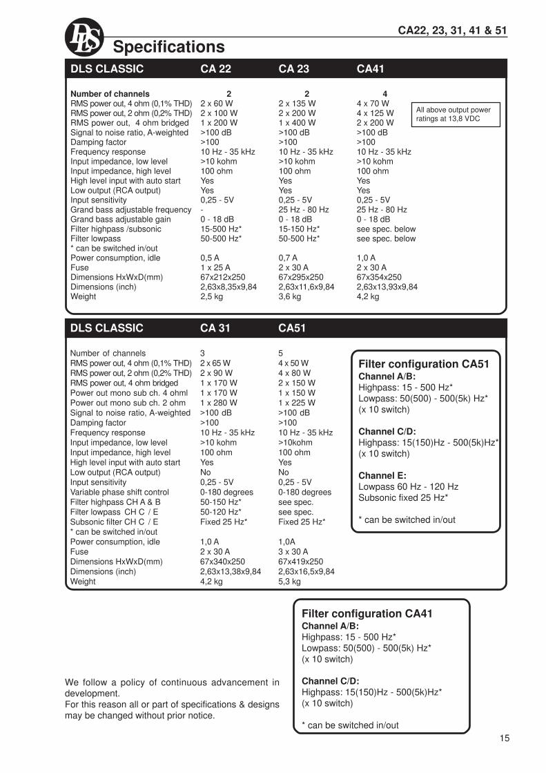
DLS CLASSIC CA 22 CA 23 CA41
Number of channels 2 2 4RMS power out, 4 ohm (0,1% THD) 2 x 60 W 2 x 135 W 4 x 70 WRMS power out, 2 ohm (0,2% THD) 2 x 100 W 2 x 200 W 4 x 125 WRMS power out, 4 ohm bridged 1 x 200 W 1 x 400 W 2 x 200 WSignal to noise ratio, A-weighted >100 dB >100 dB >100 dBDamping factor >100 >100 >100Frequency response 10 Hz - 35 kHz 10 Hz - 35 kHz 10 Hz - 35 kHzInput impedance, low level >10 kohm >10 kohm >10 kohmInput impedance, high level 100 ohm 100 ohm 100 ohmHigh level input with auto start Yes Yes YesLow output (RCA output) Yes Yes YesInput sensitivity 0,25 - 5V 0,25 - 5V 0,25 - 5VGrand bass adjustable frequency - 25 Hz - 80 Hz 25 Hz - 80 HzGrand bass adjustable gain 0 - 18 dB 0 - 18 dB 0 - 18 dBFilter highpass /subsonic 15-500 Hz* 15-150 Hz* see spec. belowFilter lowpass 50-500 Hz* 50-500 Hz* see spec. below* can be switched in/outPower consumption, idle 0,5 A 0,7 A 1,0 AFuse 1 x 25 A 2 x 30 A 2 x 30 ADimensions HxWxD(mm) 67x212x250 67x295x250 67x354x250Dimensions (inch) 2,63x8,35x9,84 2,63x11,6x9,84 2,63x13,93x9,84Weight 2,5 kg 3,6 kg 4,2 kg
DLS CLASSIC CA 31 CA51
Number of channels 3 5RMS power out, 4 ohm (0,1% THD) 2 x 65 W 4 x 50 WRMS power out, 2 ohm (0,2% THD) 2 x 90 W 4 x 80 WRMS power out, 4 ohm bridged 1 x 170 W 2 x 150 WPower out mono sub ch. 4 ohml 1 x 170 W 1 x 150 WPower out mono sub ch. 2 ohm 1 x 280 W 1 x 225 WSignal to noise ratio, A-weighted >100 dB >100 dBDamping factor >100 >100Frequency response 10 Hz - 35 kHz 10 Hz - 35 kHzInput impedance, low level >10 kohm >10kohmInput impedance, high level 100 ohm 100 ohmHigh level input with auto start Yes YesLow output (RCA output) No NoInput sensitivity 0,25 - 5V 0,25 - 5VVariable phase shift control 0-180 degrees 0-180 degreesFilter highpass CH A & B 50-150 Hz* see spec.Filter lowpass CH C / E 50-120 Hz* see spec.Subsonic filter CH C / E Fixed 25 Hz* Fixed 25 Hz** can be switched in/outPower consumption, idle 1,0 A 1,0AFuse 2 x 30 A 3 x 30 ADimensions HxWxD(mm) 67x340x250 67x419x250Dimensions (inch) 2,63x13,38x9,84 2,63x16,5x9,84Weight 4,2 kg 5,3 kg
Filter configuration CA41Channel A/B:Highpass: 15 - 500 Hz*Lowpass: 50(500) - 500(5k) Hz*(x 10 switch)
Channel C/D:Highpass: 15(150)Hz - 500(5k)Hz*(x 10 switch)
* can be switched in/out
Filter configuration CA51Channel A/B:Highpass: 15 - 500 Hz*Lowpass: 50(500) - 500(5k) Hz*(x 10 switch)
Channel C/D:Highpass: 15(150)Hz - 500(5k)Hz*(x 10 switch)
Channel E:Lowpass 60 Hz - 120 HzSubsonic fixed 25 Hz*
* can be switched in/out
All above output powerratings at 13,8 VDC

DLS Svenska ABP.O. Box 13029
SE-40251 Göteborg, SwedenTel: +46 31 840060Fax: +46 31 844021E-mail: [email protected]
www.dls.se


![BE NMPG: minutes … · Web viewSWIFT ON-GOING By Next Telco CA22 ( [Post Meeting] Action: NMPGs to inform co-chairs/SWIFT of their markets position so that the ‘Madrid’ table](https://static.fdocuments.net/doc/165x107/5f9c3166a6aa35736d7afcb9/be-nmpg-minutes-web-view-swift-on-going-by-next-telco-ca22-post-meeting.jpg)