Manual: 2001-06-19 Installation and Maintenance for Phil ...Pelethane Drop Tube Seal Drain path into...
38
ARB Approved Installation and Maintenance Manual For the Phil-Tite Phase I Vapor Recovery System Approved: June 19, 2001 Amended: July 12, 2002 Amended: September 16, 2003 Amended: April 27, 2004
Transcript of Manual: 2001-06-19 Installation and Maintenance for Phil ...Pelethane Drop Tube Seal Drain path into...

ARB Approved
Installation and Maintenance Manual
For the Phil-Tite Phase I Vapor Recovery System
Approved: June 19, 2001Amended: July 12, 2002
Amended: September 16, 2003Amended: April 27, 2004

Phil-Tite Installation and Maintenance Manual, Page 2
Summary of Maintenance Activities Required of thePhil-Tite Phase I Vapor Recovery System1
Component Interval Maintenance To Be PerformedPressure/Vacuum Vent Valve
Husky Model 4885Annual 1. Remove screws that hold top cover on.
2. Remove any debris that might be sitting inside the lowercover.
3. Check the drain holes in the lower cover for blockage.4. Do not remove the two (2) screens.5. Reinstall the top cover and retaining screws.6. Tighten the screws firmly.
Spill Container Drain ValvePhil-Tite “All Models withDrain Valves”
Every 3years
followingstartup
1. Remove standing liquid prior to testing (note: removestanding liquid following each fuel delivery).
2. Remove any debris or accumulated dirt from container.3. Test the drain valve using ARB procedure TP-201.1C or
TP-201.1D as applicable.4. If the drain valve passes testing, no further maintenance
is necessary. If the drain valve fails testing, continuewith steps 5 through 12.
5. Remove the snap-ring and foam filter from the inside ofcontainer. Inspect the foam filter, ensure that it is nottorn or damaged. Replace if necessary.
6. With the snap ring and foam filter removed, loosen theallen screw in the top clamp and remove the valveassembly by pulling up on the valve handle.
7. Remove the O-ring from the bottom of the container andinspect for cuts or damage. Replace if necessary.
8. Inspect the boot-screen assembly and ensure there areno cracks or cuts. If the boot-screen assembly requiresreplacement, loosen the allen screw on the bottomclamp and separate clamp-handle assembly from bootscreen assembly.
9. Inspect the O-ring on the shut off collar for cuts ordamage. Replace if necessary.
10. Reassemble the drain valve in reverse order. Ensurethat the valve assembly is properly adjusted so that theassembly moves up and down freely without binding.NOTE: The bail handle must snap into place whenmoved into the closed position.
11. Test the drain valve using ARB procedure TP-201.1C orTP-201.D as applicable. If a failure still persists,remove the container and inspect the flat lower sealbetween the riser and spill container. Replace ifnecessary.
12. Reinstall the container using the installation instructionsprovided and test the drain valve using ARB procedureTP-201.1C or TP-201-1D as applicable.
1 These maintenance requirements shall not circumvent use of the manufacturer’s installation andmaintenance instructions. Maintenance contractors or owner/operators shall refer to themanufacturers complete installation and maintenance instructions found herein to ensure that allmaintenance and torque requirements are met.

Phil-Tite Installation and Maintenance Manual, Page 3
Summary of Maintenance Activities Required of thePhil-Tite Phase I Vapor Recovery System1
Dust CapsOPW “All Models”
Annual Visually inspect the seal in cap and replace if damaged ormissing.
Vapor Recovery AdaptorPhil-Tite SWV-101-B
Annual The Phil-Tite rotatable adaptors are not field serviceablewith the exception of the vapor poppet or vapor poppet sealfound on the SWV-101-B.
1. Depress the vapor poppet and release. Ensure that thepoppet returns to the closed position. This will verifythat the spring mechanism is working properly.
2. Test the poppet seal by applying a soap solution to thepoppet while the underground storage tank is under apositive gauge pressure of at least 2.00 inches W.C. Ifthe facility continuously operates under vacuum, a bagtest may be used. Place a clear plastic bag over theadaptor and make sure it is sealed to the sides of theadaptor.
3. If no bubbles appear at the poppet area under positivepressure or the bag test shows no signs of the bagcollapsing, no further maintenance is required. Ifbubbles appear around the poppet seal or the bagcollapsed onto the adaptor, continue with steps 3through 10 to repair the poppet seal.
4. Remove the SWV-101-B adaptor from the spillcontainer riser using an installation tool (Phil-Tite ToolKit #T-7043-1)
5. Using a screwdriver, hook the snap ring on the inside ofthe adaptor and remove.
6. After removing the snap ring, remove the brass spider,spring and vapor poppet through the bottom of theadaptor.
7. With the vapor poppet removed inspect the poppet andpoppet seal for cuts, tears or damage. Replace ifnecessary.
8. Reassemble the vapor poppet spring and brass spiderin the reverse order from which they were removed.
9. Replace the snap ring and actuate the poppet by hand,making sure the assembly is secure and actuatesproperly.
10. Reinstall and properly torque the SWV-101-B using theprovided installation and maintenance instructions.
11. Re-test the poppet seal as described in step 1 in 2.
1 These maintenance requirements shall not circumvent use of the manufacturer’s installation andmaintenance instructions. Maintenance contractors or owner/operators shall refer to themanufacturers complete installation and maintenance instructions found herein to ensure that allmaintenance and torque requirements are met.

Phil-Tite Installation and Maintenance Manual, Page 4
Summary of Maintenance Activities Required of thePhil-Tite Phase I Vapor Recovery System1
Ball FloatsOPW “All Models”
Universal Valve Model 37Series
Every 3years
followingstartup
Every 3years
followingstartup
Visually inspect the valve for damage, contamination,corrosion, freedom of movement of the ball float and checkthe bleeder orifice for proper airflow. Replace if damaged orcorroded.
Inspect the Model 37 to ensure proper operation. Check toensure that the ball moves freely within the cage and thatthe bleed hole allows free airflow.
Drop TubesOPW 61T
Annual Visually inspect Drop Tube to see if it is installed and ensurethat the bottom of tube is within 6 inches of the bottom oftank. Test the drop tube seal with ARB procedure TP-201.1C or TP-201.1D as applicable. If the drop tube sealpasses testing, no further maintenance is required. If thedrop tube seal fails testing, replace the drop tube seal withOPW P/N: H11931M for 4” Tubes. Re-test the drop tubeseal with ARB procedure TP-201.1C or TP-201.1D asapplicable.
Drop Tube Overfill PreventionDevice
OPW 61SO-PT
Annual Annually, inspect the flapper in the 61-SO-PT to see that itis open by looking down the drop tube opening. Test the61-SO-PT seals with ARB procedure TP-201.1D. If thedrop tube passes testing, no further maintenance isrequired. If the drop tube fails testing, replace the drop tubeseal with Phil-Tite 85039-DT. Re-test the 61-SO-PT withARB procedure TP-201.1D. If this does not correct the leakthe 61-SO-PT needs to be replaced.
Tank Gauge ComponentsMorrison Brothers 305 Annual Visually inspect cap to see that it is not missing any seals
and is properly installed.
1 These maintenance requirements shall not circumvent use of the manufacturer’s installation andmaintenance instructions. Maintenance contractors or owner/operators shall refer to themanufacturers complete installation and maintenance instructions found herein to ensure that allmaintenance and torque requirements are met.

Phil-Tite Installation and Maintenance Manual, Page 5
Phil-Tite Phase I Vapor Recovery SystemInstallation, Operation and Maintenance Manual
Table of Contents
Equipment Manufacturer/Model Number Figure Page
Typical Installation (Product Side) A-1 7
Typical Installation (Vapor Side) A-2 8
Spill Container Phil-Tite B-1, B-2 9
85100-F = Product (standalone)85000-S = Product with Stainless Steel (SS) Sleeve85000-GS = Product with SS Sleeve and Gravel Shield85000-EXT = Product, external for sump configuration85100-15 = Product, 15-gallon capacity
85101-NV = Vapor (standalone)85001-NV-S = Vapor with Stainless Steel (SS) Sleeve85001-NV-GS = Vapor with SS Sleeve and Gravel Shield85001-NV-EXT= Vapor, external for sump configuration
Debris Bucket Phil-Tite PP-1005 TB (product)(required) B-3 12Phil-Tite PP-1005 TBP (vapor)(optional)
Product Adaptor Phil-Tite SWF-100-B C-1 13
Vapor Adaptor Phil-Tite SWV-101-B C-1 13
Riser Adaptor Phil-Tite M/F4X4 D-1 15
Dust Cap Morrison Brothers 323C-0100ACEVR (vapor) E-1 16Morrison Brothers 305C-0100ACEVR(product) E-1 16OPW 1711T-EVR (vapor) E-2 17OPW 634TT-EVR (product) E-2 17
Pressure/Vacuum Vent ValveHusky 4885 F-1 18
Tank Gauge Port ComponentsEver-Tite 4097AGBR (adaptor) G-1 19Ever-Tite 4097AGMBRNL (adaptor)Ever-Tite 4097MBR (cap)
Veeder-Root 312020-952 (cap & adaptor) G-2 20
Morrison Brothers 305XPA1100AKEVR G-3 21(cap and adaptor kit)
Morrison Brothers 305-0200AAEVR G-3 21(replacement adaptor)

Phil-Tite Installation and Maintenance Manual, Page 6
Morrison Brothers 305XP-110ACEVR G-3 21(replacement cap)
Extractor1 Universal V421 H-1 22OPW 233 H-2 23
Ball Float1 Universal 37 H-1 22OPW 53VML H-2 23OPW 30MV H-2 23
Drop Tube 1 OPW 61-T Straight Drop Tube I-1 25
Drop Tube Overfill Prevention Device 1
Phil-Tite 61SO-PT I-2 26
Riser Offset1 Phil-Tite M-6050 J-1 36
Double Fill1 Phil-Tite (configuration only) K-1 37
Sump Configuration1 Phil-Tite 85000-EXT-CA2 K-2 38
1 Component optional for vapor recovery system configuration; other requirements may apply.

Phil-Tite Installation and Maintenance Manual, Page 7
Figure A-1
Typical Product Side Installation Using Phil-Tite System
Pelethane Drop Tube Seal
Drain path into drop tube
Threaded Tank Riser
Phil-Tite Adaptor SWF-100B
Spill Container Lid
Phil-Tite Spill Container
Pelethane Seal
Drop tube opening must be submergedwhen liquid level is
6" deep
Tank Bung
Bottom of droptube should becut on 45 degreeangle
Dust Cap
Stainless Steel Sleeve
Large Buna Seal
1. Achieves 5 gallon capacity.2. Allows removal or installation
of container without ground
Phil-Tite Riser Adaptor M/F4X4Achieves square, flat sealing surface
Cast in concrete orattached to cntmnt. lid
breaking or lid disassembly.
Pelethane Seal
4 " m i n .
4" min.
Phil-Tite 61-SO-PT Overfill Prevention Device(OPTIONAL)

Phil-Tite Installation and Maintenance Manual, Page 8
Figure A-2
Typical Vapor Recovery Side Installation Using Phil-Tite System
Threaded tank riser
Phil-Tite Adaptor SWV-101B
Spill Container Lid
Stainless Steel Sleeve
Pelethane Seal
Tank Bung
Dust Cap
Ball Float Vent Valve (OPTIONAL)
Phil-Tite Spill Container
Threaded Fitting w/ Extractor
Large Buna Seal
1. Achieves 5 gallon capacity.
Bleed Hole
1. Sized to actuate at 90% tank capacityor 30 minutes prior to tank overfill.
of container without ground
2. Appropriate sizing may be based on SWRCBrequirements and manufacturers specifications.
Cast in concrete or attached to cntmnt. lid
2. Allows removal or installation
breaking or lid disassembly.
Pelethane Seal
4" min.
Achieves square, flat sealing surfacePhil-Tite Riser Adaptor M/F4X4

Phil-Tite Installation and Maintenance Manual, Page 9
Figure B-1
Phil-Tite Product Spill Containers, 85100-F, 85000-S, 85000-GS, 85000-EXT and 85100-15Phil-Tite Vapor Spill Containers, 85101-NV, 85001-NV-S, 85001-NV-GS, and 85001-NV-EXTAdd performance specs
Product Vapor Recovery

Phil-Tite Installation and Maintenance Manual, Page 10

Phil-Tite Installation and Maintenance Manual, Page 11
Figure B-2
Phil-Tite 85011 Spill Container Lid

Phil-Tite Installation and Maintenance Manual, Page 12
Figure B-3
Phil-Tite Debris BucketPart Number PP 1005 TB (Product) (required)Part Number PP 1005 TBP (Vapor) (optional)
Phil-Tite Hand Pump EP-400-VB (optional)

Phil-Tite Installation and Maintenance Manual, Page 13
Figure C-1
Phil-Tite SWF-100-B Rotatable Product Adaptor andPhil-Tite SWV-101B Rotatable Vapor Adaptor
Add toque, 360 performance specs
Product
Vapor Recovery

Phil-Tite Installation and Maintenance Manual, Page 14

Phil-Tite Installation and Maintenance Manual, Page 15
Figure D-1
Phil-Tite Model M/F4X4 Riser Adaptor

Phil-Tite Installation and Maintenance Manual, Page 16
Figure E-1
Morrison Brothers Adaptor Dust Caps323C-0100ACEVR (vapor adaptor dust cap)
305C-0100ACEVR (product adaptor dust cap)
TO BE FILLED OUT BYINSTALLER/MAINTENANCE PERSON
Name of Maintenance Service Company:_____________________________________________________
Address:_____________________________________________________
_____________________________________________________
Date of Install: ________________________________________
Name and Location of Install:_____________________________________________________
_____________________________________________________
Morrison Bros. Co.24th & Elm St.Dubuque, IA 52001
WARRANTY CARDAll Morrison products are thoroughly tested before shipment and onlymaterial found to be defective in manufacture will be replaced. Claimsmust be made within one year from the date of installation, andMorrison Bros. Co. will not allow claims for labor or consequentialdamage resulting from purchase, installation, or misapplication of theproduct.
Expiration Date: __________________________________
Item No: ________________________________________
This card must be returned to manufacturer forwarranty to be honored.

Phil-Tite Installation and Maintenance Manual, Page 17
Figure E-2
OPW 634TT-EVR and 1711T-EVR Dust Caps
Operation and Maintenance:Annually inspect seal for nicks, tears or deformations. If required replace with OPW P/N: H15005M for634TT and H10886M for 1711T.
Standard Product Warranty OPW warrants that products sold by it are free from defects in materials and workmanship for a period of one year from thedate of manufacture by OPW (ECO products two years from date of manufacture.) Proof of purchase may be required. As theexclusive remedy under this limited warranty, OPW, will at its sole discretion, repair, replace, or issue credit for future orders forany product that may prove defective within the one year date of manufacture period (repairs, replacements, or credits may besubject to prorated warranty for remainder of the original warranty period, complete proper warranty claim documentationrequired.) This warranty shall not apply to any product that has been altered in any way, which has been repaired by any partyother than a service representative authorized by OPW, or when failure is due to misuse, or improper installation or maintenance.OPW shall have no liability whatsoever for special, incidental or consequential damages to any party, and shall have no liabilityfor the cost of labor, freight, excavation, clean up, downtime, removal, reinstallation, loss of profit, or any other cost or charges. For any product certified to California 2001 standards, OPW warrants that product sold by it are free from defects in materialand workmanship for a period of one year from date of manufacture or one year from date of registration of installation not toexceed 15 months from date of manufacture by OPW.
THIS WARRANTY IS IN LIEU OF ALL OTHER WARRANTIES, EXPRESS OR IMPLIED, AND SPECIFICALLY THEWARRANTIES OF MERCHANTABILITY AND FITNESS FOR A PARTICULAR PURPOSE. THERE ARE NOWARRANTIES, WHICH EXTEND BEYOND THE DESCRIPTION ON THE FACE HEREOF.
P.O. Box 405003 * Cincinnati, Ohio 45240-50031-800-422-2525 Domestically513-870-3315 Internationally
www.opw-fc.com

Phil-Tite Installation and Maintenance Manual, Page 18
Figure F-1Send a copy to Art
Husky Model 4885 2-Inch Threaded Pressure/Vacuum Vent Valve
PRESSURE VACUUM VENT WARRANTYINFORMATION
Husky Corporation will, at its option, repair, replace,or credit the purchase price of any Husky manufacturedPressure Vacuum Vent which proves upon examinationby Husky, to be defective in material and/orworkmanship within EIGHTEEN (18) MONTHS fromthe date of shipment for any Husky Pressure VacuumVent, except as otherwise provided herein. For all otherHusky manufactured product, see Husky Form No.PS2002-Term (4/15/02) at www. husky.com. The warranty period on repaired or replacementproduct is only for the remainder of the warrantyperiod. Buyer must return the products to Husky,transportation charges prepaid. This Warranty does notapply to equipment or parts which have been installedimproperly, damaged by misuse, improper operation ormaintenance, or which are altered or repaired in anyway other than by Husky. The Warranty provisions contained herein applyONLY to original purchasers and subsequentcommercial purchasers within the warranty period whouse the equipment for commercial or industrialpurposes. THERE ARE NO OTHER WARRANTIESOF MERCHANTABILITY, FITNESS FOR APARTICULAR PURPOSE, OR OTHERWISE, ANDANY OTHER SUCH WARRANTIES ARE HEREBYSPECIFICALLY DISCLAIMED. Husky assumes NO LIABILITY for labor charges orother costs incurred by Buyer incidental to the service,adjustment, repair, return, removal or replacement ofproducts. HUSKY ASSUMES NO LIABILITY FORANY INCIDENTAL, CONSEQUENTIAL, OROTHER DAMAGES UNDER ANY WARRANTY,EXPRESS OR IMPLIED, AND ALL SUCHLIABILTY IS HEREBY EXPRESSLY EXCLUDED. Husky reserves the right to change or improve thedesign of any Husky fuel dispensing equipment withoutassuming any obligations to modify any fuel dispensingequipment previously manufactured.
HUSKY CORPORATION l 2325 HUSKY WAYl PACIFIC, MO 63069 www.husky.com PHONE: 800-325-3558
009063– 0 6/5/02
PRESSURE/VACUUM VENT MODEL 4885INSTALLATION AND MAINTENANCE
INSTRUCTIONS
INSTALLATIONThe P/V Vent is designed to fit on top of a 2" vent pipe.Remove the P/V Vent from the carton and visually inspect forany shipping damage.
Model 4885 Thread-On P/V VentApply fuel resistant pipe sealant to the threads on the 2” ventstack. Screw the P/V Vent onto the vent stack and tighten to arange of 20 to 50 ft-lbs with a suitable wrench. DO NOTOVER-TIGHTEN. Periodic maintenance is recommended (seebelow).
MAINTENANCEAnnually inspect the P/V Vent valve for foreign objectswithout removing the P/V Vent valve from the vent pipe byusing the following procedure:
1. Remove the screws that hold the top cover on.2. Remove any debris that might be sitting inside thelower cover.3. Check the drain holes in the lower cover for blockage.4. The two (2) screens should not be removed.5. Reinstall the top cover and retaining screws.6. Tighten the screws firmly.
NOTE: DO NOT ALTER OR COVER THE P/V VENTTESTING CRITERIA
Leak rate: Pressure = .05 CFH at 2” WC, Vacuum = .21 CFH at -4”WC.Cracking Pressure: 2 ½” to 3 ½” WC, Vacuum = -6” to -10” WC.Per ARB procedure TP-201.1E or the applicable ARB ExecutiveOrder.
HUSKY CORPORATION l 2325 HUSKY WAY l PACIFIC, MO 63069 www.husky.com PHONE: 800-325-3558
009041 – 6 9/19/03 (REVERSE SIDE IS 009063)

Phil-Tite Installation and Maintenance Manual, Page 19
Figure G-1
Ever-Tite Tank Gauge Port Components
Ever-Tite #4097AGBRAdaptor with Hex Base
Installation Instructions
1. Thread by hand to avoid cross threading.
2. Tighten adaptor to 75 to 100 foot-pounds torque.
WarrantyThe Company warrants its goods to be free from defects in materialand workmanship as represented in our catalogs or applicabledrawings and specifications agreed to by us at the timeof acceptance of the order by Ever-Tite Coupling Products.Our obligation under this warranty shall be limited to repairingor replenishing any parts which shall, within one (1) year aftershipment to the original purchaser, be demonstrated to bedefective. This warranty is expressly in lieu of all other warranties,express or implied, including the warranties of merchantabilityand fitness. No person, firm or corporation is authorizedto assume for us any other liability in connection with the saleof these goods.
Ever-Tite #4097MBR CapEver-Tite #4097AGMBRNLAdaptor
Phil-Tite Installation and Maintenance Manual, Page 20
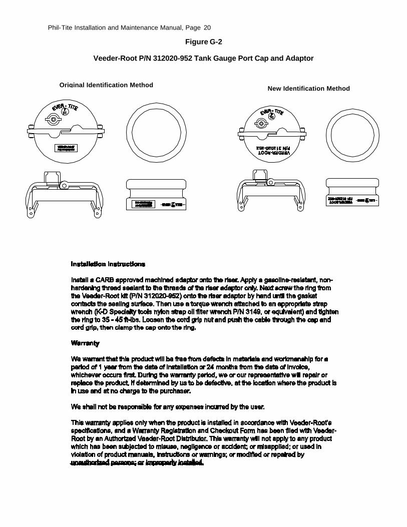
Figure G-2
Veeder-Root P/N 312020-952 Tank Gauge Port Cap and Adaptor
Original Identification Method New Identification Method

Phil-Tite Installation and Maintenance Manual, Page 21
Figure G-3
Morrison Brothers Tank Gauge Port Components305XPA & 305XPA1100AKEVR (cap and adaptor kit)
305 & 305-0200AAEVR (replacement adaptor)305XP & 305XP-110ACEVR (replacement cap)
305XP CapInstallation Instructions –
1. Apply a fuel resistant, non-hardening, anti-seize sealant (not adhesive) to cableconnector threads. Follow manufacturer’s instructions for installation of monitoringsystem.
2. Set cap on adapter3. Push down on lever arms.
305 AdapterInstallation Instructions –
1. Apply a fuel resistant, non-hardening, anti-seize sealant (not adhesive) to bodythreads.
2. Thread body on to riser pipe. Torque to 23-26 ft.-lb.
Morrison Bros. Co.24th & Elm St.Dubuque, IA 52001
WARRANTY CARDAll Morrison products are thoroughly tested before shipment and onlymaterial found to be defective in manufacture will be replaced. Claimsmust be made within one year from the date of installation, andMorrison Bros. Co. will not allow claims for labor or consequentialdamage resulting from purchase, installation, or misapplication of theproduct.
Expiration Date: __________________________________
Item No: ________________________________________
This card must be returned to manufacturer forwarranty to be honored.
TO BE FILLED OUT BYINSTALLER/MAINTENANCE PERSON
Name of Maintenance Service Company:_____________________________________________________
Address:_____________________________________________________
_____________________________________________________
Date of Install: ________________________________________
Name and Location of Install:_____________________________________________________
_____________________________________________________

Phil-Tite Installation and Maintenance Manual, Page 22
Figure H-1
Universal Model Number 37 Series Ball Float Vent ValveAnd Model V421 Series Extractor Fitting
Installation Instruction for Model 37 SeriesFloat Vent Valve and Model V421 Extractor Fitting
Universal Valve Co., Inc.478 Schiller StreetElizabeth, NJ 07206Phone: (800) 223 –0742Fax: (908) 351-0369 Copyright 2002 Universal Valve Co., Inc.
1. Apply a non-hardening, gasoline resistant, pipe compound to thethreads of Model 37 before installing the unit into the cageassembly of the Universal Model V421 Extractor Fitting.Tighten the Model 37 into the cage assembly to a torque ofapproximately 45 ft.-lbs.
2. Apply a non-hardening, gasoline resistant, pipe compound to thethreads of the cage assembly to facilitate removal at a later date.Install the cage assembly into the Model V421 to a torque ofapproximately 45 ft-lbs. Use caution when installing the cageassembly into the Model V421. Do not over tighten. Make surethe ball moves freely.
3. Apply a non-hardening, gasoline resistant, pipe compound to thethreads of the Extractor Fitting and hand tighten the assemblyinto the tank bung. Tighten the Extractor Assembly into the tankto a torque of approximately 150 ft.-lbs.
Maintenance
Every 3 following startup, inspect the Model 37 to ensure properoperation. Check to ensure that the ball moves freely within thecage and that the bleed hole allows free airflow.
WARNING! This product is only to be used on gravity dropsystems. DO NOT use this product if the tank is being filled bymeans of a pump.

Phil-Tite Installation and Maintenance Manual, Page 23
Figure H-2
OPW Model 53VML 30MV Ball Float Vent Valves and 233 Extractor
OPW Installation and Maintenance Instructions 53VML / 30MV SERIES BALL FLOATS AND 233 SERIES EXTRACTOR ASSEMBLIES
IMPORTANT: Please read these warnings and use the assembly instructions completely and carefully before starting. Failure to do so may cause product failure, or result in environmental contamination due to liquid leakage into the soil, creating hazardous spill conditions. IMPORTANT: Check to make sure the unit is intact and undamaged and all parts have been supplied. Never substitute parts for those supplied. Doing so may cause product failure and void warranty. WARNING-DANGER: Using electrically operated equipment near gasoline or gasoline vapors may result in a fire or explosion, causing personal injury and property damage. Be sure that the working area is free from such hazards, and always use proper precautions. NOTE: At all times when product is in the storage tank keep the riser pipe capped, so the vapors cannot escape into the environment. Notice: OPW products must be used in compliance with applicable federal, state, and local laws and regulations. Product selection should be based on physical specifications and limitations and compatibility with the environment and material to be handled. All illustrations and specifications in this literature are based on the latest production information available at the time of publication. Prices, materials, and specification are subject to change at any time, and models may be discontinued at any time, in either case, without notice or obligation.
WARNING: OPW Overfill Warning Systems should only be used on submerged pumping systems, and not w ith suction pump systems. OPW Overfill Warning Systems should only be used on gravity drop systems. DO NOT use w here Pump Off Unloading is used. IMPORTANT: Installing the incorrect length OPW 53VML or 30MV Ball Float Vent Valve for your specific application may result in delivery flow restriction at tank levels exceeding requirements established by the U.S. EPA. Always consult the appropriate tank charts and determine the specifics of your tank installation to determine the appropriate length OPW 53VML or 30MV to be installed. The illustration and instructions on the back of this sheet are intended to serve as a guide in this determination. Field Installation Instructions 1. Apply a non-hardening, gasoline resistant pipe compound on the ball float nipple threads. Install the
extractor cage-assembly onto the ball float nipple. To rques for, 3"NPT thread, 125 ft-lbs min. to 200 ft-lbs max, 2"NPT thread, 100 ft-lbs min. to 150 ft-lbs max. DO NOT USE TEFLON TAPE
2. Thread the 233 Series OPW Extractor Fitting into the tank bung fitting. Torque for, 4"NPT thread, 125" ft-lbs min. to 250 ft-lbs max. Thread the Ball Float and cage assembly into the 233 extractor fitting using the OPW 89 Extractor Wrench. Torque for, 3 3/ 4-8 thread, 75 ft-lbs min. to 150 ft-lbs max.
3. Make sure Ball Float moves freely, full stroke, without binding. 4. Preventative Maintenance - Every three years, remove and inspect the valve for damage,
contamination, corrosion, freedom of movement of the ball float, and check the bleeder orifice for proper airflow. Replace if damaged or corroded.
Important: Leave these instructions with Station Operator. Standard Product Warranty: OPW warrants that products sold by it are free from defects in materials and workmanship for a period of one year from the date of manufacture by OPW (ECO products two years from date of manufacture.) Proof of purchase may be required. As the exclusive remedy under this limited warranty, OPW, will at its sole discretion, repair, replace, or issue credit for future orders for any product that may prove defective within the one year date of manufacture period (repairs, replacements, or credits may be subject to prorated warranty for remainder of the original warranty period, complete proper warranty claim documentation required.) This warranty shall not apply to any product that has been altered in any way, which has been repaired by any party other than a service representative authorized by OPW, or when failure is due to misuse, or improper installation or maintenance. OPW shall have no liability whatsoever for special, incidental or consequential damages to any party, and shall have no liability for the cost of labor, freight, ex cavation, clean up, downtime, removal, reinstallation, loss of profit, or any other cost or charges.
For any product certified to California 2001 standards, OPW warrants that product sold by it are free from defects in material and workmanship for a period of one year from date of manufacture or one year from date of registration of installation not to exceed 15 months from date of manufacture by OPW. THIS WARRANTY IS IN LIEU OF ALL OTHER WARRANTIES, EXPRESS OR IMPLIED, AND SPECIFICALLY THE WARRANTIES OF MERCHANTABILITY AND FITNESS FOR A PARTICULAR PURPOSE. THERE ARE NO WARRANTIES, WHICH EXTEND BEYOND THE DESCRIPTION ON THE FACE HEREOF.
IMPORTANT: The figures in this installation and maintenance instruction may contain vapor recovery equipment (including model numbers) that is not certified by the California Air Resources Board (CARB) for a specific Phase I Vapor Recovery System. Please refer to Exhibit 1 of the appropriate CARB Phase I Executive Order for a list of certified Phase I Vapor Recovery System Equipment.

Phil-Tite Installation and Maintenance Manual, Page 24
Specifying OPW 53VML AND 30MV Ball Float Vent Valves IMPORTANT: Dimensions are for installations without Overfill Prevention Drop Tubes. See Drop Tube installation for reference on those installations. Specifying the Proper Length 53VML Series Ball Float Step 1: Determine Dimension "X": Consult the tank chart (provided by the tank manufacturer) to determine the distance that
corresponds to 10% of the total tank capacity Step 2: Determine Dimension "Y": Measure the dimension from the inside top of the tank to the top of the 4" threaded tank
"bung" fitting. Step 3: Add measurements "X" and "Y". Then subtract 1/4"and round up to the nearest length ball float. Specifying the Proper Length 30MV Series Ball Float Step 1: Determine Dimension "X": Consult the tank chart (provided by the tank manufacturer) to determine the distance that
corresponds to 308 gallons. Step 2: Determine Dimension "Y": Measure the dimension from the inside top of the tank to the top of the 4" threaded tank
"bung" fitting. Step 3: Add measurements "X" and "Y". Then subtract 1/4 " and round up to the nearest length ball float.
P.O. Box 405003 * Cincinnati, Ohio 45240-5003 1-800-422-2525 Domestically 513-870-3315 Internationally
www.opw-fc.com
Copyright, 2003- OPW Fueling Components Inc., Cincinnati, OH Printed in U.S.A. p/n H14111PA (9/ 03)

Phil-Tite Installation and Maintenance Manual, Page 25
Figure I-1
OPW 61T Drop Tube
O-Ring
Installation Instructions1. Cut the tube to a length so that it is not more than 6” from the bottom of the tank or per localcodes or requirements. Saw off the excess tube at a 45-degree angle and file off any sharpburrs.
Operation and Maintenance:Annually: Test the drop tube seal with ARB procedure TP-201.1C or TP-201.1D. If the droptube seal passes testing, no further maintenance is required. If the drop tube seal fails testing,replace the drop tube seal with OPW P/N: H11931M for 4” Tubes. Re-test the drop tube sealwith ARB procedure TP-201.1C or TP-201.1D.
Standard Product Warranty OPW warrants that products sold by it are free from defects in materials and workmanship for a period of one yearfrom the date of manufacture by OPW (ECO products two years from date of manufacture.) Proof of purchase maybe required. As the exclusive remedy under this limited warranty, OPW, will at its sole discretion, repair, replace, orissue credit for future orders for any product that may prove defective within the one year date of manufacture period(repairs, replacements, or credits may be subject to prorated warranty for remainder of the original warranty period,complete proper warranty claim documentation required.) This warranty shall not apply to any product that has beenaltered in any way, which has been repaired by any party other than a service representative authorized by OPW, orwhen failure is due to misuse, or improper installation or maintenance. OPW shall have no liability whatsoever forspecial, incidental or consequential damages to any party, and shall have no liability for the cost of labor, freight,excavation, clean up, downtime, removal, reinstallation, loss of profit, or any other cost or charges.
For any product certified to California 2001 standards, OPW warrants that productsold by it are free from defects in material and workmanship for a period of one yearfrom date of manufacture or one year from date of registration of installation not toexceed 15 months from date of manufacture by OPW.
THIS WARRANTY IS IN LIEU OF ALL OTHER WARRANTIES, EXPRESS OR IMPLIED, AND SPECIFICALLY THEWARRANTIES OF MERCHANTABILITY AND FITNESS FOR A PARTICULAR PURPOSE. THERE ARE NOWARRANTIES, WHICH EXTEND BEYOND THE DESCRIPTION ON THE FACE HEREOF.

Phil-Tite Installation and Maintenance Manual, Page 26
Figure I-2
Phil-Tite Model 61-SO-PT Drop Tube Overfill Prevention Device
MAY 2003
PHIL-TITE ENTERPRISES, INC.
INSTALLATION and MAINTENANCE INSTRUCTIONS FOR THEPHIL-TITE 61-SO-PT DROP TUBE OVERFILL PREVENTION VALVE.
IMPORTANT: Please read these assembly and installation instructions completelyand carefully before starting.
Installation & MaintenanceInstructions

Phil-Tite Installation and Maintenance Manual, Page 27
GENERAL INSTRUCTIONS
The Phil-Tite 61SO-PT Overfill Prevention Valve isdesigned for tight fill, gravity drop applications tohelp prevent accidental or intentional overfilling ofunderground storage tanks. It is installed in the USTdrop tube in place of a standard drop tube.The main 61SO-PT valve closes when liquid level isat 95% of the top of the tank. A small bypass valveremains open to allow the delivery hose to drain at3-5 gallons per minute. If the delivery truck valve isnot closed after initial shut-off, the bypass valve willclose and will restrict all fuel delivery.
The 61SO-PT models of the 61SO-PT are designedto be installed with a PHIL-TITE Spill Container andPHIL-TITE M/F 4 X 4 adaptor.
IMPORTANTRead these assembly and installation instructionscompletely and carefully prior to starting. Check tomake sure all parts have been provided. Use onlythe parts supplied; substitution of parts may causeproduct failure.
Failure to follow instructions may cause improperproduct operation or premature failure which maypermit storage tank overfill. An overfilled storagetank may create hazardous conditions and/orenvironmental contamination.
CAUTIONDo not remove elastic band from around float untilinstructed to do so, as damage to valve may result.
WARNINGFailure to properly connect delivery hose and elbow,and/or disconnecting a liquid filled delivery hose orelbow will result in a hazardous spill, which mayresult in personal injury, property damage, fire,explosion, and water and soil pollution.• Make sure all connections, including the hose
and elbow connections, between storage tankand transport are securely coupled.
• Make sure the lip seal and/or all gaskets in thedelivery elbow are properly in place to preventspills.
• Do not operate with damaged or missing parts,which prevent tight connections.
Normal Operation: A Hose ”Kick” and reduced flowsignal that the tank is full. Close transport deliveryvalve and drain hose into tank before disconnectingany hose fitting.
Overfilled Tank: Failure of the hose to drain afterclosing the delivery valve signals an overfilled tank.Do Not Disconnect any delivery hose fitting until theliquid level in the tank has been lowered to allow thehose to drain into the tank. Attention: In the eventyou are splashed, remove all wetted clothingimmediately. Do not go into an enclosed area andstay away from ignition sources.
IMPORTANTDetermine if the underground storage tank isequipped with a ball float vent valve asillustrated in Figure 16. In all systems, the shut-off point of the 61SO-PT must be reached beforethe ball float reduces flow to ensure properoverfill valve operation.
TOOLS NEEDED FOR INSTALLATION ANDASSEMBLY:1. Tape measure2. Hacksaw or cut-off saw, fine tooth; 24 teeth/inch3. Fine half round file4. PHIL-TITE Flaring tool5. Two-part sealant (supplied) (JB Weld 8276)
WARNINGUsing electrically operated equipment near gasolineor gasoline vapors may result in fire or explosion,causing personal injury and property damage.Check to assure the working area is free from suchhazards, and always use proper precautions.
Important: The figures in this installation andmaintenance instruction may contain vaporrecovery equipment (including model number)that is not certified by the California AirResources Board (ARB) for a specific Phase IVapor Recovery System. Please refer to Exhibit 1of the appropriate ARB Phase I Executive Orderfor a list of certified Phase I Vapor RecoverySystem Equipment.
HOW TO LOCATE THE POSITION OF THEPhil-Tite 61SO-PT (61-SO-PT) AT 95% TANKCAPACITY
The length of the upper tube and the placement ofthe 61S0-PT valve body determine the shut-offpoint. Following the standard instructions for the

Phil-Tite Installation and Maintenance Manual, Page 28
61SO-PT will provide for initial shutoff at 95%. Alllength measurements are in inches.
INSTRUCTIONS
1.) Find tank capacity (in gallons) from tankcalibration chart provided by tank manufacturer.
2.) Calculate 95% of capacity.
3.) Locate the 95% volume number on the tankcalibration chart.
4.) Find the dipstick number (X) which correspondsto the 95% tank volume. And, find the dipsticknumber (Y) which corresponds to the100%volume.
5.) Subtract the dipstick number (X) from the tankdiameter (Y) to find the upper tube referencenumber (Z).(Y) - (X) = (Z)
6.) Subtract 2" from (Z) to find the upper tube depth(C).(Z) - 2" = C
7.) Is C less than 6 ½” ?
NO Upper tube length is C plus the distancefrom the top of the M/F 4 X 4 Adapterinstalled on the riser pipe to the inside, toplip of the storage (A).
Upper Tube Length = C + (A)
YES Upper tube length is 6 ½” plus the distanceto the top of the Riser Adaptor (Dim “A”).
NOTE: You must find the actual tank capacitynumber that correlates to the 6 ½” + (A) depthfor the station records. This number may alsobe used for the purposes of calibrating anelectronic tank level system.
® Registered T.M. - Owens Corning Fiberglass Corporation
Bottom of storage tank
B To tank Bottom
A To Tank Top ID
Riser Including M/F 4X4 adaptor
Measure stick
EXAMPLE1.) For an Owens-Corning Model G-3 Fiberglass®
Tank Calibration Chart:Tank Capacity - 10,000 gal., nominal 9,403 gal.
NOTE: Use actual capacity only
2.) 95% of actual tank capacity = 0.95 x9403 gal. = 8933 gal.
3.) The closest number which is less than 8933 gal.Is 8910 gal. Choosing the closest number lessthan 95% of actual capacity ensures that theinitial shutoff will occur when the tank is no morethan 95% full.
4.) The calibration chart reading of 8910 gal.corresponds to a dipstick measurement of 82".
5.) Dipstick number (X) = 82"Tank diameter (Y) = 92"
(X) - (Y) = (Z) (92 "- 82" = 10")(Z) = 10"
6.) (Z) - 2" = C (10" - 2" = 8")C = 8"
7.) Is 8" less than 6 ½”?
NO Measure from the top of the M/F 4 X 4Adaptor to the inside, top lip, of the storagetank, measurement (A) (see Figure 1).
Upper tube length = 8” + (A)

Phil-Tite Installation and Maintenance Manual, Page 29
ASSEMBLY INSTRUCTIONS
IMPORTANT: Each of the numbered steps in theinstallation instructions are designed as a CHECKLIST to insure proper installation and trouble freeoperation of the 61SO-PT Overfill Prevention Valve.
Read and follow these steps carefully, checkingthem off as you proceed.
Figure numbers correspond to step numbers foreasy reference.
STEP 1: MEASURE MINIMUM UPPER TUBELENGTH REQUIREDInstall the PHIL-TITE M/F 4 X 4 adaptor on the tankriser (Refer to the Installation Instructions Supplied).Insert the 61SO-PT measuring stick through the riserpipe and hook it under the inside of the tank in thelengthwise direction. Mark the measuring stick atthe top of the PHIL-TITE M/F4 X 4 Adaptor (SeeFigure 1 &1A).
STEP 2: MARK THE MINIMUM UPPER TUBELENGTHUsing the measuring stick, transfer the minimumlength required measurement to the tube as shownin Figure 2. This is NOT a cut mark.
STEP 3: MEASURE DIMENSION A AND BUsing a tape measure, measure the distance fromthe top of the PHIL-TITE M/F 4 X 4 Adaptor to theinside top lip of the tank (Dim “A”). Measure fromthe top of the PHIL-TITE M/F 4 X 4 Adaptor to thebottom of the tank (Dim. “B”). See Figure 1. Theseresults will assist in determining proper position.
IMPORTANT: Inspect the riser pipe for any foreignmaterial. Over spray from tank relining or anyinternal burrs inside of pipe must be removed priorto installation. Failure to have an unobstructed riserpipe may prevent proper installation and operation ofthe valve. The 61SO-PT is designed to be installedinto schedule 40 riser pipes. The 61SO-PT cannotbe installed into schedule 80 riser pipes.
STEP 4: MARK THE 95% UPPER TUBE LEGNTHUse the result obtained for “C” from HOW TOLOCATE THE POSITION OF THE 61SO-PT AT95% TANK CAPACITY. Measure off a distanceequal to result “C” above the mark created in Step 2(furthest away from the valve). This is NOT a cutmark. This mark identifies the distance required toposition the valve at 95% tank capacity.
Bottom of storage tank
B To tank Bottom
A To Tank Top ID
Riser Including M/F 4X4 adaptor
Measure stick
Figure 1
Spill Collector
Drop Tube
Drop Tube Gasket
M/F 4X4 Adaptor
Tank Riser
Figure 1A
Measuring Stick
Seam
Transfer Mark From Stick to Upper Tube (Cut Line)
Figure 2
Phil-Tite Installation and Maintenance Manual, Page 30
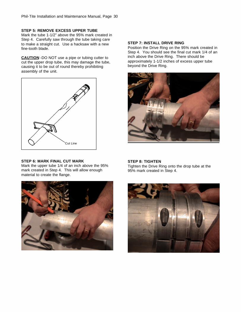
STEP 5: REMOVE EXCESS UPPER TUBEMark the tube 1-1/2” above the 95% mark created inStep 4. Carefully saw through the tube taking careto make a straight cut. Use a hacksaw with a newfine-tooth blade.
CAUTION -DO NOT use a pipe or tubing cutter tocut the upper drop tube, this may damage the tube,causing it to be out of round thereby prohibitingassembly of the unit.
Cut Line
STEP 6: MARK FINAL CUT MARKMark the upper tube 1/4 of an inch above the 95%mark created in Step 4. This will allow enoughmaterial to create the flange.
STEP 7: INSTALL DRIVE RINGPosition the Drive Ring on the 95% mark created inStep 4. You should see the final cut mark 1/4 of aninch above the Drive Ring. There should beapproximately 1-1/2 inches of excess upper tubebeyond the Drive Ring.
STEP 8: TIGHTENTighten the Drive Ring onto the drop tube at the95% mark created in Step 4.
Phil-Tite Installation and Maintenance Manual, Page 31
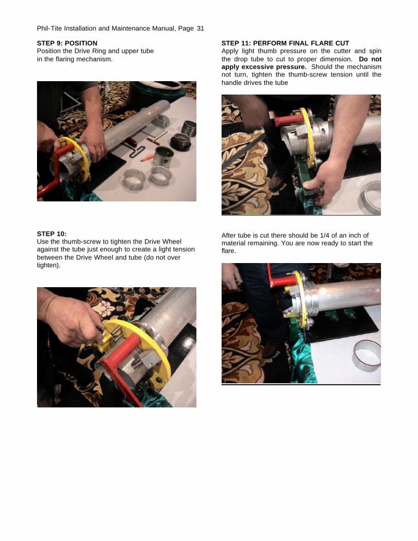
STEP 9: POSITIONPosition the Drive Ring and upper tubein the flaring mechanism.
STEP 10:Use the thumb-screw to tighten the Drive Wheelagainst the tube just enough to create a light tensionbetween the Drive Wheel and tube (do not overtighten).
STEP 11: PERFORM FINAL FLARE CUTApply light thumb pressure on the cutter and spinthe drop tube to cut to proper dimension. Do notapply excessive pressure. Should the mechanismnot turn, tighten the thumb-screw tension until thehandle drives the tube
After tube is cut there should be 1/4 of an inch ofmaterial remaining. You are now ready to start theflare.

Phil-Tite Installation and Maintenance Manual, Page 32
STEP 12: FIRST FLARING WHEEL POSITIONThe first position for the flaring wheel is on the lowermount (45 degrees).
Apply light tension using the Allen bolt and startspinning the tube. Apply continual pressure until thetube begins to flare slightly. Should the drivemechanism not turn, apply more pressure with thethumb-screw.
STEP 13: INTERMEDIATE FLARING POSITIONRe-Mount the Flaring Wheel on the next anglemount to increase the amount of flare. Repeat theflaring procedure as used in Step 10.
STEP 14: REMOVE THE FLARING WHEEL ANDDRIVE RINGAfter the flaring procedure is completed, thereshould be smooth, flat 90-degree flare. Remove theFlaring Wheel and Drive Ring from the upper tube.
STEP 15: INSPECTIONInspect the flare to ensure the flare is flat and even.

Phil-Tite Installation and Maintenance Manual, Page 33
Hold Float Down While Inserting Drop Tube
STEP 16: INSTALL DROP TUBE SEALInstall the drop tube seal supplied with thePHIL-TITE M/F 4X4.
STEP 17: LOWER TUBE ASSEMBLY If a vise is used, clamp on the valve body castingonly to avoid damage to the float. Mix the two-partepoxy provided until the color is uniform. Using themixing stick, generously apply epoxy to the first 6male threads on the valve body as shown in figure10. Make sure coverage is completely around thethreads, and work the sealant down into the threadprofile. Quickly thread the lower tube onto the valvebody. Tighten the tube securely by hand or with astrap wrench. Remove excess sealant and smoothsealant bead with water moistened mixing stick.
Important: Allow sealant (epoxy) to curefor 4-6 hours before installing into tank.
Apply Sealant completely around first 6 threads.
Figure 19
Note: After the sealant has cured and beforeinstalling the tube into the tank, a pressure test canbe performed on the valve to check for vaportightness. Seal off both ends of the tube withinflatable plumber’s plugs. Apply a maximum 10"W.C. (1/3 PSI) air pressure. If pressure does nothold and a leak can be located with soap solution,do not install the valve. Send the valve back toPHIL-TITE for warranty evaluation.Caution: Do not over-pressure. Excess pressurecan damage the valve
STEP 18: CUT LOWER TUBE AT 45° ANGLEMeasuring from the underside of the inlet tubeflange, mark the overall length of the drop tube adistance of (B) minus 6" or as per local codes orrequirements. Determine dimension (B) from themeasurements taken in Step 3, Figure 1 (Top of thePHIL-TITE M/F 4 X 4 Adaptor to the bottom of thetank). Saw off the excess tube at a 45-degree angle
and file off any sharp burrs (Refer to Figure 16).Optional: Install the PHIL-TITE Tank BottomProtector on the lower tube (Refer to Installationinstructions supplied with the 6110-PT Tank BottomProtector).
STEP 19: PREPARE TANK RISERFOR VALVE INSERTION
IMPORTANT: Inspect the riser pipe for any foreignmaterial. Over spray from tank relining or anyinternal burrs inside of pipe must be removed priorto installation. Failure to have an unobstructed riserpipe may prevent proper installation or operation ofthe valve. Thoroughly clean top of riser pipe.Important: Before installing the drop tube, allowthe sealant to cure for 4-6 hours.
STEP 20: REMOVE ELASTIC BANDRemove the elastic band securing the float to thevalve body. The float will move into an outwardposition.
STEP 21: INSTALL DROP TUBEMake sure the drop tube gasket is installed. Holdthe float down against the valve body and slowlyinsert the drop tube into the riser pipe. Do not forcethe valve into the riser pipe. If any obstruction orforeign matter interferes with smooth insertion of thevalve, the riser pipe must be cleared.
WARNINGFailure to follow the assembly and installationinstructions or use of excessive force to insertthe 61SO-PT will VOID THE WARRANTY!

Phil-Tite Installation and Maintenance Manual, Page 34
STEP 22: CHECK INSTALLATIONInsert the drop tube all the way into the tank until theflange and gasket seat onto the top of the Phil-TiteM/F 4 X 4 Adapter. The float will swing out into theoperating position as it passes into the tank.Make sure that the float is aligned along the lengthof the tank. The length of the tank can easily bedetermined by locating other manholes or pumpboxes that are installed around other tank fittings.Look into the drop tube and align the deflector withthe length of the tank. CAUTION: No obstruction inthe tank can be within 13" from the center of theriser pipe or the valve may not operate properly.
Align Float Along Length of Tank
Vapor Recovery Riser
Fill Riser
6” Max.
OPW 53V or 30MV Ball Float
13” Min. Clearance for Float
Tube Cut per Local Requirements
6” (or as per local requirements)
STEP 23: FINAL INSTALLATIONInstall a PHIL-TITE Spill Container according to themanufacturer’s installation instructions. Ensure thatthe drop tube does not rotate while tightening theSpill Container by observing the position of thedeflector. Install a PHIL-TITE Rotatable adaptor andtighten according to the manufacturer’s installationinstructions.
STEP 24: INSTALL WARNING PLATE
Slide the tie wrap over the warning plate ears andposition warning plate against riser pipeapproximately 1" below the adaptor. Tighten the tiewrap securely. The valve is now fully installed andin operating position.
STEP 25: VALVE REMOVALThe valve can be removed from the tank byremoving the PHIL-TITE Spill Container. Reinstallper the above instructions.
Figure 26
Figure 25

Phil-Tite Installation and Maintenance Manual, Page 35
Step 26: Electronic Liquid Level MonitoringIf an electronic level monitor is installed, it must be calibrated to match the top of the 61SO-PT valvebody, correlated to the 95% tank level dimension used during assembly.
PREVENTATIVE MAINTENANCEAnnually, inspect the flapper in the 61-SO-PT to see that it is open by looking down the drop tubeopening. Test the 61-SO-PT seals with ARB procedure TP-201.1D. If the drop tube passes testing, nofurther maintenance is required. If the drop tube fails testing, replace the drop tube seal with Phil-Tite85039-DT. Re-test the 61-SO-PT with ARB procedure TP-201.1D. If this does not correct the leak the61-SO-PT needs to be replaced.
CAUTION: Do not insert any foreign object into drop tube if flapper is in the closed position. Forexample a tank level measuring stick. This will damage the valve and void the Warranty.ALWAYS check the valve position before “sticking” the tank. If valve is in the closed position thetank is either over filled and you need to wait until the liquid level goes down or the 61SO-PT isdamaged and needs to be replaced.
Phil-Tite 61SO-PT Performance Specifications:This Overfill Prevention Valve has been manufactured and tested to, and met the following specifications:
Specification: Leak rate, Less than or equal to 0.17 CFH at 2.00"W.C.
Important: Leave these installation instructions and maintenance procedures with the station operator.

Phil-Tite Installation and Maintenance Manual, Page 36
Figure J-1
Phil-Tite Model M-6050 Vapor Recovery Riser Offset
Phil-Tite M-6050 Vapor Riser OffsetINSTALLATION:
(1) On the underground storage tank, measure the tank bungs from center to center and then subtract 16 inchesfrom that measurement. The result will match the size of the M-6050 Vapor Riser Offset required which alsoincludes additional space for connections or fittings.
Example: If the tank bungs measure out to 22 inches center to center and you subtract 16 inches, you will havea maximum size, 6-inch M-6050 Vapor Riser Offset for your application.
(2) Apply a gasoline resistant, non-hardening thread sealant to the TANK END ONLY of the M-6050 using thesealant manufacturers recommended instructions. The use of sealant on the spill container end varies bymanufacturer.
(3) By hand, thread the M-6050 into the pipe coupler or threaded fitting depending on your configuration (seefigures). By hand, thread the entire assembly onto the underground storage tank.
Note: If a Ball Float Vent Valve is to be installed, you must use a threaded connection to allow the installationand removal of the Ball Float Vent Valve.
(4) Tighten the M-6050 and threaded fittings to a torque value between the range of 150 and 200 Ft-lbs .
Offset Using Ball FloatOffset Using Straight Riser

Phil-Tite Installation and Maintenance Manual, Page 37
Figure K-1
Typical Phil-Tite Double Fill Configuration

Phil-Tite Installation and Maintenance Manual, Page 38
Figure K-2
Phil-Tite 85000-EXT-CA2 Sump ConfigurationUsing Fiberlite FL 36-inch diameter Raised Composite Cover
Phil-Tite 85000-EXT SpillContainer withpermanently installednylon ring (no stainlesssteel sleeve required).
Original Phil-Tite85000 Spill Containerswithout stainless steelsleeves.