Manual · 1.4 Theory of Operation The OMC-150 is a cup and vane anemometer. Cup and vane...
38
Manual | OMC-150 Status: Final | Not confidential Page 1 | 38 V2.13 Manual OMC-150 Version: 2.13 Status: Final Date: 25 October 2019 Author: Observator www.observator.com
Transcript of Manual · 1.4 Theory of Operation The OMC-150 is a cup and vane anemometer. Cup and vane...

Manual | OMC-150
Status: Final | Not confidential
Page 1 | 38
V2.13
Manual
OMC-150
Version: 2.13
Status: Final
Date: 25 October 2019
Author: Observator
www.observator.com

Manual | OMC-150
Status: Final | Not confidential
Page 2 | 38
V2.13
Document history
The Observator range is in continuous development and so specifications may be subject to change
without prior notice. When in doubt about the accuracy of this document, contact the Observator Group.
Reference documents
Type of document / tool Product type and name (incl. url)
Software N.A.
Datasheet OMC-150
Manual OMC-150
Revision history
Date Amendments Company, position
1992-11-01 Initial document creation Observator instruments
2000-5-29 V1.2 incorporating junction box
2003-8-27 V2.02 rewritten for ATEX certification,
incorporating plug connection
2004-1-29 V2.03 some typing errors corrected
2005-5-1 V2.04 minor error corrected (7core vs 8core)
2007-5-1 V2.05 annex G added
2013-4-1 V2.06 update certification (IECEx added) Review
version
2013-8-1 V2.07 Version 2.06 including all updated certificates
2015-12-1 V2.08 Update CE declaration
2016-12-1 V2.09 Update maintenance section
2017-5-1 V2.10 Update EU declaration
2019-1-2 V2.11 Update IP rating
2019-2-1 V2.12 Update DoC
2019-10-25 V2.13 Update DoC & style

Manual | OMC-150
Status: Final | Not confidential
Page 3 | 38
V2.13
Preface
This manual provides information for the best performance and safe application of the OMC-150
anemometer. This manual is intended for the engineers who are responsible for site planning, installation,
commissioning and maintenance of the intrinsically safe OMC-150 anemometer. Professional knowledge
on mechanical and electrical systems in potentially explosive atmospheres is required for the users of this
manual. This manual does not cover the OMC-156 junction box or the OMC-158 interface unit. These
units will come with their own documentation.
When an enumeration in this manual is numbered, it denotes a particular sequence. If the enumeration is
marked with dots, there is no special sequence.
Read this manual carefully before starting the installation of the Observator OMC-150 anemometer. Keep
this manual after installation for future reference.

Manual | OMC-150
Status: Final | Not confidential
Page 4 | 38
V2.13

Manual | OMC-150
Status: Final | Not confidential
Page 5 | 38
V2.13
Table of contents
1 Introduction ..................................................................................................................... 7
1.1 Utilisation ............................................................................................................................................. 7 1.2 General arrangement .......................................................................................................................... 7 1.3 Basic Specifications ............................................................................................................................ 8 1.4 Theory of Operation ............................................................................................................................ 8 1.5 Conditions of use. ................................................................................................................................ 8
2 Description ...................................................................................................................... 9
2.1 General ................................................................................................................................................ 9 2.2 Main parts ............................................................................................................................................ 9 2.3 Moving parts ........................................................................................................................................ 9 2.4 Electrical .............................................................................................................................................. 9 2.5 Layout of a wind system ...................................................................................................................... 9
3 Operation ........................................................................................................................10
3.1 General .............................................................................................................................................. 10 3.2 Measurement of wind speed ............................................................................................................. 10 3.3 Measurement of wind direction ......................................................................................................... 10
4 Safety ..............................................................................................................................11
4.1 Safety measures by the design of the OMC-150 anemometer ......................................................... 11 4.2 System integration - interconnection to the other system components ............................................ 11 4.3 Required personnel qualification and remaining risks ...................................................................... 12
5 Handling, transportation and storage ...........................................................................13
5.1 Handling ............................................................................................................................................ 13 5.2 Long term storage ............................................................................................................................. 13 5.3 Reshipping the instrument ................................................................................................................. 13
6 Installation ......................................................................................................................14
6.1 Unpacking.......................................................................................................................................... 14 6.2 Location of the sensor ....................................................................................................................... 14 6.3 Location of the sensor ....................................................................................................................... 14 6.4 Mounting / mechanical installation .................................................................................................... 14 6.5 Assembly of cup and vane ................................................................................................................ 15 6.6 Alignment of the wind vane ............................................................................................................... 16 6.7 Electrical installation .......................................................................................................................... 17
7 Commissioning ..............................................................................................................18
8 Faults, support, and service ..........................................................................................19
8.1 Faults ................................................................................................................................................. 19 8.2 Support, service and warranty........................................................................................................... 20
9 Maintenance ...................................................................................................................21
9.1 Maintenance schedule (preventive maintenance)............................................................................. 21 9.2 Removing the OMC-150 anemometer from its location .................................................................... 21 9.3 Recalibration...................................................................................................................................... 22

Manual | OMC-150
Status: Final | Not confidential
Page 6 | 38
V2.13
10 End of operational life ...................................................................................................23
Appendix A: Typical system layout .......................................................................................24
Appendix B: OMC-150 Specifications ....................................................................................26
Appendix C: Drawings ............................................................................................................27
Appendix D: Spare Parts ........................................................................................................30
Appendix E: OMC-150 Marking ..............................................................................................31
Appendix F: ATEX certificate .................................................................................................32
Appendix G: IECEx certificate ................................................................................................34
Appendix H: EU Declaration of Conformity ...........................................................................37

Manual | OMC-150
Status: Final | Not confidential
Page 7 | 38
V2.13
1 Introduction
1.1 Utilisation
The OMC-150 anemometer is designed to measure wind speed and wind direction in harsh environments
including potentially explosive atmospheres. Typical application areas are offshore industry, petrochemical
industry, and transportation. All exposed parts are made in non-corrosive materials, therefore the OMC-
150 anemometer is ultimate suitable for marine environment.
1.2 General arrangement
Figure 1 General Arrangement
Manual | OMC-150
Status: Final | Not confidential
Page 8 | 38
V2.13
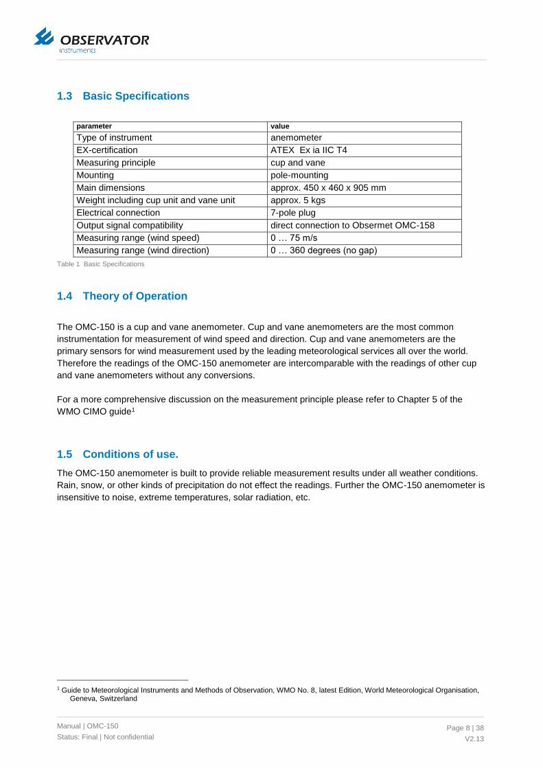
1.3 Basic Specifications
parameter value
Type of instrument anemometer
EX-certification ATEX Ex ia IIC T4
Measuring principle cup and vane
Mounting pole-mounting
Main dimensions approx. 450 x 460 x 905 mm
Weight including cup unit and vane unit approx. 5 kgs
Electrical connection 7-pole plug
Output signal compatibility direct connection to Obsermet OMC-158
Measuring range (wind speed) 0 … 75 m/s
Measuring range (wind direction) 0 … 360 degrees (no gap)
Table 1 Basic Specifications
1.4 Theory of Operation
The OMC-150 is a cup and vane anemometer. Cup and vane anemometers are the most common
instrumentation for measurement of wind speed and direction. Cup and vane anemometers are the
primary sensors for wind measurement used by the leading meteorological services all over the world.
Therefore the readings of the OMC-150 anemometer are intercomparable with the readings of other cup
and vane anemometers without any conversions.
For a more comprehensive discussion on the measurement principle please refer to Chapter 5 of the
WMO CIMO guide1
1.5 Conditions of use.
The OMC-150 anemometer is built to provide reliable measurement results under all weather conditions.
Rain, snow, or other kinds of precipitation do not effect the readings. Further the OMC-150 anemometer is
insensitive to noise, extreme temperatures, solar radiation, etc.
1 Guide to Meteorological Instruments and Methods of Observation, WMO No. 8, latest Edition, World Meteorological Organisation,
Geneva, Switzerland

Manual | OMC-150
Status: Final | Not confidential
Page 9 | 38
V2.13
2 Description
2.1 General
While reading this chapter please refer to the dimensional drawing in Appendix C:For detailed
specifications please refer to Appendix B:
2.2 Main parts
The OMC-150 anemometer consists of a sensor body and a mounting bracket. Note that the mounting
bracket, though it is sometimes referred to as OMC-157, is an integral part of the OMC-150 anemometer.
The mounting bracket has a mast clamp and an electrical plug connector. This clamp is designed for
mounting on a vertical pipe end.
2.3 Moving parts
The only moving parts are the cup unit and the vane unit. The vane unit is mounted on top of the sensor
body, and the cup unit is mounted under the sensor body. Both the cup unit and the vane unit are wind
driven. The wind speed sensor is a rotary cup type unit manufactured in stainless steel and polycarbonate.
The three cups are cone shaped for optimum response to varying winds. The vane unit is made in
stainless steel.
2.4 Electrical
The electrical circuit for wind speed measurement and the electrical circuit for wind direction measurement
are not interconnected. The speed sensor is a proximity switch with a 2-wire “NAMUR” signal on
connections E and F; the direction sensor is a dual wiper potentiometer with a 360 degree winding (no
gap). It has two supply connections A and B, and two wiper connections C and D. For details see section
3.3.
2.5 Layout of a wind system
The following accessories are supplied with the OMC-150 anemometer:
pigtail cable with mating connector to the OMC-150 anemometer
U-bolts with small mounting materials
In order to build a complete wind system, the following components may be required. These components
must be ordered separately:
OMC-156 Junction box for cable extension
Field cabling
OMC-158 interface unit
Calibration certificate (see also section 0)

Manual | OMC-150
Status: Final | Not confidential
Page 10 | 38
V2.13
See Appendix A: for a typical system layout. Note that the maximum length of the field cable, which runs
from the junction box (nearby the OMC-150 anemometer) through the Ex zone to the OMC-158-2
interface unit, is up to 1 km (depending on the cable quality).
3 Operation
3.1 General
The numbers in parenthesis refer to the item numbers on the assembly drawings in
3.2 Measurement of wind speed
The cup unit (6) is driven by the wind. There is an almost linear dependency between wind speed and
rotational velocity of the cup unit. The proportional factor is 1.68 meters per revolution. The cup unit is
connected to a shaft (12), which drives a metal slotted code cap (16). The transitions between the metal
partitions and the slots in this code cap generate pulses by means of an inductive proximity switch (10).
The code cap generates 8 pulses per revolution, so each pulse represents 0.21 meters
3.3 Measurement of wind direction
The stainless steel vane unit (4, 5) is driven by the wind. It turns until the counterweight (5) directs into the
wind direction. The position of the vane unit is transmitter through the shaft (12) and the coupling (17, 18)
to the dual wiper potentiometer (8). Figure 2 shows the typical output voltage in relation to the vane
position.
0 V
0 º 90 º 180 º 270 º 360 º
C
D
N E S W N
Figure 2 Output voltage on terminals C and D of the dual wiper potentiometer

Manual | OMC-150
Status: Final | Not confidential
Page 11 | 38
V2.13
4 Safety
4.1 Safety measures by the design of the OMC-150 anemometer
The OMC-150 anemometer is a Category 2 G device, certified for use in potential explosive atmospheres
(gas explosion) in zone 1 and zone 2. The method of protection of the OMC-150 anemometer is intrinsic
safety (Ex-i) according to EN-60079-0 and EN-60079-11. A risk analysis was performed on the
mechanical construction of the instrument, both for operation during normal use and for anticipated faults,
according to EN13463-1.
4.2 System integration - interconnection to the other system components
As the OMC-150 anemometer is an intrinsic safe device, it should be connected through certified zener
barriers. All connections A through F are 'floating' with respect to earth. The three zener barriers must
comply to the following safety description, while used with both channels (A-B, C-D or E-F) interconnected
with no earth return:
Zener barriers on connections A-B and C-D:
Ui 20V, Ii 150mA, Pi 125 mW
Zener barriers on connections E-F:
Ui 16V, Ii 52mA, Pi 169 mW
The zener barriers limit the voltage with respect to earth.
Examples of suitable barriers are given in Table 2.
Manufacturer Barrier Type for pins A-B
and C-D
Barrier Type for pin E-F Remarks
MTL2 7761Pac 77423
Pepperl & Fuchs Z961.H
CEAG4 SB-1761 SB-1351
Stahl 9002/22-093-040-00
Table 2 Applicable zener barriers
The OMC-158-2 interface unit does contain suitable barriers. No separate barriers are needed when the
OMC-158 -2 interface unit is applied.
Note that all components in the intrinsic safe loops of the OMC-150 anemometer must be suitable for use
in the designated zone.
2 MTL instruments , internet www.mtl-inst.com 3 The MTL 7742 is an active barrier which requires external power supply 4 CEAG Apparatenbau Hundsbach GmbH & Co. KG, internet www.ceag.de

Manual | OMC-150
Status: Final | Not confidential
Page 12 | 38
V2.13
4.3 Required personnel qualification and remaining risks
The engineers who handle the OMC-150 anemometer during installation, commissioning and
maintenance must have professional knowledge on mechanical and electrical systems in potentially
explosive atmospheres.
The engineers that are handling the OMC-150 anemometer at the point of installation must be aware of
the risks of working at height. Local Safety regulations on site must be adhered to. Adequate Personal
Protective Equipment must be used where necessary.
Remind that the cup unit and vane can easily turn, and can turn unexpected. Keep safe distance to these
moving parts during work at the sensor location.

Manual | OMC-150
Status: Final | Not confidential
Page 13 | 38
V2.13
5 Handling, transportation and storage
5.1 Handling
Keep the instrument in the protective Styrofoam package until installation. Care should be taken not to
damage the cup unit the vane unit. Take care that the small mounting materials will not be lost.
Once the installed, store the packing for later use (see section 5.3)
5.2 Long term storage
When not in use, store the OMC-150 anemometer in a dry place. Note that this is required, as the system
is only weatherproof when mounted in an upright position while the electrical plug is mated.
5.3 Reshipping the instrument
Whenever the OMC-150 anemometer is shipped, e.g. for calibration or repair, it should be shipped in the
original packing. If this is no longer available on site, replacement packing can be ordered from
Observator instruments B.V. or one of their world-wide agents or resellers. For contact information please
refer to section 8.2.
If the anemometer is shipped for calibration, please also include the vane unit and cup units, as those
parts are required during calibration.

Manual | OMC-150
Status: Final | Not confidential
Page 14 | 38
V2.13
6 Installation
6.1 Unpacking
The scope of supply of the OMC-150 anemometer consists of a foam filled cardboard box containing:
sensor body with integral mounting arm
cup unit
vane unit
U-bolts
mounting materials
5 meters cable with plug
Note that additional materials that were simultaneously ordered for the same order might be packed in the
OMC-150 box.
6.2 Location of the sensor
Ensure that the OMC-150 anemometer will be mounted on a location that is free from turbulence from
obstacles. Plan the OMC-150 anemometer in a free area as far as practicable. For guidance on the best
location refer to the WMO CIMO Guide 5. The location must be accessible for maintenance.
6.3 Location of the sensor
Ensure that the OMC-150 anemometer will be mounted on a location that is free from turbulence from
obstacles. Plan the OMC-150 anemometer in a free area as far as practicable. For guidance on the best
location refer to the WMO CIMO Guide 6. The location must be accessible for maintenance.
6.4 Mounting / mechanical installation
First connect the mounting clamp to the mast / pipe end. The top of the mounting clamp must be mounted
less than 30 mm under the end of the pipe to prevent the pipe end blocking the wind flow to the cup unit.
Securely tighten the nuts on the U-bolts, preventing the nuts vibrating loose.
Connect now the plug (bayonet). The plug must be protected against salt spray e.g. using vulcanising
tape. The sensor cable must be properly supported, and fastened to prevent exerting force on the
connector.
5 Guide to Meteorological Instruments and Methods of Observation, WMO No. 8, latest Edition, World Meteorological Organisation,
Geneva, Switzerland, ISBN 92-63-16008-2 6 Guide to Meteorological Instruments and Methods of Observation, WMO No. 8, latest Edition, World Meteorological Organisation,
Geneva, Switzerland, ISBN 92-63-16008-2

Manual | OMC-150
Status: Final | Not confidential
Page 15 | 38
V2.13
Figure 1 Mechanical installation
6.5 Assembly of cup and vane
The wind-sensors are shipped with the wind vane and cups disconnected from their appropriate units. On
the common unit, the upper spindle is for the wind direction sensor, and the lower spindle for the wind
speed sensor. To prevent damaging the wind vane and cups, properly mount the sensor/bracket
combination on the mast before fitting the wind vane and cup-unit. (this may not always possible)
The shafts of the OMC-150 anemometer and the inside of the cup unit and vane unit are conical. This
enables fastening of the capped nut without the shaft turning along.
The cup unit and the vane blade are made in light materials for optimum response on the wind. Both are
balanced to provide accurate measurement and to prevent vibration. Take care not to damage the cup
unit or the vane blade while mounting.

Manual | OMC-150
Status: Final | Not confidential
Page 16 | 38
V2.13
Place the vane unit and mounting materials on the upper shaft in the following sequence:
1) Vane unit 2) Plain washer 3) Capped nut
Place the cup unit and mounting materials on the lower shaft in the following sequence:
1) Cup unit 2) Spring washer 3) Capped nut
6.6 Alignment of the wind vane
The wind direction sensor needs alignment to North. The wind direction sensor has on the wind direction
head a dot marking (figure 2). This dot marking is in most cases opposite of the mounting arm and must
be aligned to North.
The wind direction vane can only be installed in one
position on the axis due to a small iron pin. With the
sensor installed in such a way that the dot in pointing to
the North the indicator will show the correct wind direction.
Locate the North direction, using a hand hold compass or
similar. Unscrew the nuts of the complete sensor and
rotate the sensor so, that the red dot points to the North.
Figure 2 North alignment dot
REMARK : Depending on local circumstances, it may be more practical to first align the wind vane with
the sensor mounting bracket and adjust the wind vane shaft until the LED’s light. The mounting bracket
can then be aligned to the North by rotating the complete mast, thus aligning the wind vane to the North.
Note that the accuracy of the wind direction reading of the OMC-150 anemometer depends fully on the
alignment of the vane!

Manual | OMC-150
Status: Final | Not confidential
Page 17 | 38
V2.13
6.7 Electrical installation
Connections
The OMC-150 anemometer is provided with a plug to connect the sensor (through a junction box) to the
field cabling. The anemometer has a 7-core signal cable with common screen wired to the plug.
connector
pin
sensor internal
wiring colour
sensor cable wire
colour
speed/
direction
description
A red white direction potentiometer supply (+3.3V)
B blue brown direction potentiometer supply (0V)
C orange green direction potentiometer signal 0º
D yellow yellow direction potentiometer signal 90º
E black grey speed NAMUR +
F brown pink speed NAMUR -
G yellow/green blue chassis
Table 3 Connector wiring
The field cables should be properly supported, and fastened to prevent exerting force on the terminals.
Cable extension
The length of extension cable is limited to a maximum of 240 m cabling in addition to the supplied 5
meters pigtail. A 3-pair instrumentation cable (control signal cable) with individual screened twisted pairs
and a minimum conductor size of 0.75 mm2 and blue outer sheath should be used. Further requirements
might apply, dependant on the installation site (e.g. minimum conductor size, halogen content, flame
retardancy, classification, etc.)
The total loop capacitance, loop inductance, and L/R ratio of the installation must be checked not to
exceed the allowed limits (EX installation requirements) using the parameters of the selected cable.

Manual | OMC-150
Status: Final | Not confidential
Page 18 | 38
V2.13
7 Commissioning
Commissioning procedure
It is impossible to calibrate the OMC-150 anemometer in the field. However, the following procedure
makes sure that the installation was successful.
1) Check the connections 2) Install the interface and (if applicable) the display instrument. Normally the OMC-150 anemometer is
powered through the interface unit. 3) Check the direction readings. A various wind directions, make sure that the change in reading
corresponds to the direction of the vane. For interpretation of the wind direction reading, remind that the wind direction is defined as the direction where the wind comes from. The readings should be reasonable
4) Check the wind speed reading. Table 4 can be used for estimation of the actual wind speed. The reading should be reasonable
Force
[Bft]
Speed Name
Conditions at sea Conditions on land
knots m/s
0 < 1 <0.2 Calm Sea like a mirror. Smoke rises vertically.
1 1-3 0.3-1.5 Light air Ripples only. Smoke drifts and leaves rustle.
2 4-6 1.6-3.3 Light breeze Small wavelets (0.2 m). Crests
have a glassy appearance.
Wind felt on face.
3 7-10 3.4-5.5 Gentle breeze Large wavelets (0.6 m), crests
begin to break.
Flags extended, leaves move.
4 11-16 5.5-7.9 Moderate
breeze
Small waves (1 m), some
whitecaps.
Dust and small branches move.
5 17-21 8.0-10.7 Fresh breeze Moderate waves (1.8 m), many
whitecaps.
Small trees begin to sway.
6 22-27 10.8-13.8 Strong breeze Large waves (3 m), probably
some spray.
Large branches move, wires
whistle, umbrellas are difficult to
control.
7 28-33 13.9-17.1 Near gale Mounting sea (4 m) with foam
blown in streaks downwind.
Whole trees in motion,
inconvenience in walking.
8 34-40 17.2-20.7 Gale Moderately high waves (5.5
m), crests break into spindrift.
Difficult to walk against wind.
Twigs and small branches blown
off trees.
9 41-47 20.8-24.4 Strong gale High waves (7 m), dense foam,
visibility affected.
Minor structural damage may
occur (shingles blown off roofs).
10 48-55 24.5-28.4 Storm Very high waves (9 m), heavy
sea roll, visibility impaired.
Surface generally white.
Trees uprooted, structural
damage likely.
11 56-63 28.5-32.6 Violent storm Exceptionally high waves (11
m), visibility poor.
Widespread damage to
structures.
12 64+ >32.6 Hurricane 14 m waves, air filled with
foam and spray, visibility bad.
Severe structural damage to
buildings, wide spread
devastation.
Table 4 Beaufort scale

Manual | OMC-150
Status: Final | Not confidential
Page 19 | 38
V2.13
8 Faults, support, and service
8.1 Faults
Manifestation of fault Possible cause Solution
zero reading for
both windspeed and
wind direction
electrical problem;
check if the sensor is powered;
check plug connection at
sensor,
check wiring
fixed reading for
wind direction ,
correct reading for
wind speed
vane is moving electrical problem;
check wiring;
vane is not
moving
mechanical problem;
check the sensor for dirt and
worn bearings
Contact
Observator in case
of bearings
reading for wind
speed too low (not
zero)
cup unit turning
too slow
wind flow is blocked; check the
location of the OMC-150
anemometer (any obstacles?)
move the OMC-
150 anemometer if
necessary
mechanical problem;
check the sensor for dirt and
worn bearings
Contact
Observator in case
of bearings
cup unit turning at
normal speed
misinterpretation of the output
signal (e.g. factor 10 or
conversion factor for m/s to
knots or MPH)
wind flow is blocked; check the
location of the OMC-150
anemometer (any obstacles?)
move the OMC-
150 anemometer if
necessary
zero reading for
wind speed, correct
reading for wind
direction
cup unit turning electrical problem;
check wiring
cup unit not
turning
mechanical problem; check the
sensor to for dirt and worn
bearings
Contact
Observator in case
of bearings
Table 5 Faults
Notes:
Regular maintenance as described in section 9 will prevent most faults in the operation of the OMC-150 anemometer.
Please refer to section 9 for details on the proposed solutions

Manual | OMC-150
Status: Final | Not confidential
Page 20 | 38
V2.13
8.2 Support, service and warranty
Support, service, and warranty on Obsermet equipment are provided by the company where the product
was purchased. Make sure that you have the following information available when contacting
Type and model of equipment
Serial number
Original order number and year of purchase
If it is impossible to find out where the instrument was purchased, please contact the manufacturer:
Observator instruments
Rietdekkerstraat 6
2984BM Ridderkerk
The Netherlands
Tel. + 31 180 463 411
Fax + 31 180 463 530
http://www.observator.com
Purchase of replacements:
Technical support:
Service and warranty:

Manual | OMC-150
Status: Final | Not confidential
Page 21 | 38
V2.13
9 Maintenance
9.1 Maintenance schedule (preventive maintenance)
Initial maintenance interval is 1 year under normal circumstances. Maintenance is best planned in the
season when outside work is most comfortable.
For critical applications (where wind data is of major importance) under severe conditions, an initial
maintenance interval of 6 months might be considered.
The maintenance interval can be adjusted depending on the maintenance experience.
Periodic maintenance comprises inspection on the following points.
check ball bearings; contact Observator when they need replacement.
check cabling and cable support
check mounting; retighten if necessary
clean the sensor if necessary
Refer to section 6 for more information about the mechanical aspects. If the ball bearings require
replacement, the OMC-150 anemometer must be removed from its location.
The OMC-150 may only be opened and serviced by a qualified engineer certified by Observator Instruments! An exchange service is available, contact your reseller or Observator Instruments if you require maintenance.
9.2 Removing the OMC-150 anemometer from its location
1) First remove the vane unit and the cup unit.
The cup unit and the vane blade are made in light materials for optimum response on the wind. Both are
balanced to provide accurate measurement and to prevent vibration.
Take care not to damage the cup unit or the vane blade while mounting or disassembly.
The shafts of the OMC-150 anemometer and the inner side of the cup unit and vane unit are conical. After
removal of the capped nut and washer or O-ring, it might require a careful tap to loose the cup unit or vane
unit from its shaft.
2) Unplug the electrical connector. Prevent water ingress in the cable part plug during the period that the OMC-150 anemometer is disconnected.
3) Loose the U-bolts and remove the OMC-150 body from its location.

Manual | OMC-150
Status: Final | Not confidential
Page 22 | 38
V2.13
9.3 Recalibration
If the OMC-150 anemometer is included in a calibration program, the recommended calibration interval is
2 years. If required, you can adjust this interval.
Calibration of wind speed sensor is only possible in a wind tunnel. Observator instruments b.v. provides
calibration services. For address details see section 8.2. Always include the cup unit and the vane unit
when the OMC-150 anemometer is shipped for recalibration.

Manual | OMC-150
Status: Final | Not confidential
Page 23 | 38
V2.13
10 End of operational life
If the OMC-150 is at the end of it operational life, it must be disposed in accordance to the local
regulations at that time. The main materials of the OMC-150 anemometer are stainless steel.

Manual | OMC-150
Status: Final | Not confidential
Page 24 | 38
V2.13
Appendix A: Typical system layout
Example with OMC-158-2

Manual | OMC-150
Status: Final | Not confidential
Page 25 | 38
V2.13
Example with OMC-158 (old):

Manual | OMC-150
Status: Final | Not confidential
Page 26 | 38
V2.13
Appendix B: OMC-150 Specifications
parameter value
Type of instrument Anemometer
Measuring principle Cup and vane
Certification ATEX Ex ia IIC T4 Gb
ATEX group and category II 2 G
ATEX Certificate number
IECEx 02 Ex ia IIC T4 Gb
IEXEx Certificate number
Measuring system ISO – Metric
Materials of exposed parts Stainless steel
Material of cups Polycarbonate with carbon black as antistatic
Ingress Protection IP-x6 according to EN-60529
Operation Temperature -25 … +70 deg. C
Humidity 5 … 90%
Measuring range (wind speed) 0 … 75 m/s
Accuracy (wind speed) Better than 2 %
Threshold (speed) Approx. 0.3 m/s
Distance constant 1.68 meters
Measuring range (wind direction) 0 … 360 º (no gap)
Direction accuracy (non-linearity etc.) 2 degrees
Output signal compatibility Direct connection to Obsermet OMC-158
Speed signal NAMUR signal according to IEC/EN-60947-5-6
Direction supply voltage 3.3 V nom.
Direction signals Dual 0..+3.3V analogue voltage signals
Electrical connector type ITT Canon CA 3102E 16S-1
Pigtail cable length 5 meters
Pigtail cable type Screened blue signal cable, LAPP Ölflex EB-CY
8x0.75 mm2 or equivalent.
Overall height (excluding mating plug) Approx. 905 mm
Overall width (vane mounted) Approx. 460 mm max.
Mounting method Pole-mounting bracket with U-bolts (M10) for
mounting on cylindrical or square pole
Clamping range 35 to 60 mm
Weight Approx. 5 kgs. excluding cable
Packing dimensions 1050 x 510 x 150 mm
Packing weight 10 kgs

Manual | OMC-150
Status: Final | Not confidential
Page 27 | 38
V2.13
Appendix C: Drawings
Filenr. Title Version Comment
OMC-150 OMC 150 21-5-03 Dimensional drawing
OMC-150-3 OMC 150 21-5-03 Assembly drawing
OMC-150-6 OMC 150 MOUNTINGARM 22-5-03 Assembly drawing

Manual | OMC-150
Status: Final | Not confidential
Page 28 | 38
V2.13
OMC-150 dimensional drawing
A3
OM
C 1
50
DR
AW
N:
SC
AL
E:
DA
TE
:
SIZ
E:
M.A
. m
m 1:2
.5
NA
ME
:
OM
C150
21-5
-03
124
36
5
54
0
230 115
21
0
54
28
450

Manual | OMC-150
Status: Final | Not confidential
Page 29 | 38
V2.13
OMC-150 Mounting Arm
A3
OM
C 1
50
MO
UN
TIN
GA
RM
31
21
30
DR
AW
N:
SC
ALE
:
FIL
EN
R.:
DA
TE
:
SIZ
E:
CH
EC
KE
D:
RE
MA
RK
S:
FA
X: +
31-(0
)180-4
63530
TE
L.: +
31-(0
)180-4
63422
OB
SE
RV
AT
OR
INS
TR
UM
EN
TS
B.V
.
M.A
.m
m
1:2
NA
ME
:
OM
C150-6
22-5
-03
150
67
250
575
ø54
63
213
100

Manual | OMC-150
Status: Final | Not confidential
Page 30 | 38
V2.13
Appendix D: Spare Parts
Spare Parts List
Reference is made to the item numbers in drawing filenr. OMC150-3 and OMC-150-6
Order number Name Dimensions Drawing
item no.
OMC-9169 Set
ball bearings
for speed or
direction shaft
Precision ball bearing 10x19x7mm 14
Retaining ring DIN-471A, St.st. 10mm
Precision ball bearing 8x22x9mm 13
Retaining ring DIN-471A, St.st. 8mm
Set of small
mounting
materials and
O-rings
2 O-rings small 28
2 O-rings 42x2mm NBR70 27
Plain washer M6 A2 DIN-125A 26
Spring washer M6 A2 DIN-127 25
Capped nut M6 A1 DIN-1587 24
OMC-9151 Dual Wiper Potentiometer SCP40-8266A 8
OMC-9156 Proximity switch P&F SJ3,5N 10
OMC-9166 Cup assembly for OMC-150 /
OMC-160
OMC-9155 Vane assembly 4
OMC-9150 Shaft for speed or direction head 12
Set of U-bolts 2 U-bolt St.st, 68mm pitch, M10 30
2 Plain washers M10
2 Nuts M10 A4

Manual | OMC-150
Status: Final | Not confidential
Page 31 | 38
V2.13
Appendix E: OMC-150 Marking
Project OMC-150Subject Marking plateRev E Date 12 July 2013Document no OMC-150 marking.xls
Manufacturer : Observator Instruments b.v.
Rietdekkerstraat 6
2984 BM Ridderkerk
The Netherlands
CE mark : 0344
Type : OMC-150
ATEX : II 2 G IECx IECEx: Ex ia IIC T4 Gb
CENELEC : Ex ia IIC T4 Gb
Certificate no. : DEKRA 13ATEX0119, IECEx DEK 13.0012
Parameters : pin A-B and C-D: Ui=20V Ii=150mA
Pi=125mW Ci=0nF Li=1mH
pin E-F: Ui=16V Ii=52mA Pi=169mW
Ci=50nF Li=250µH
Ta : - 25 ºC … 70 ºC
Year of manufacture : 2013
Serial no. : 15000
Notes: 0344 is the identification number of the notified body
that is involved in the production control stage
Year of manufacture according to actual year of manufacture
Serial number to be completed by adding three engraved digits
Material Specifications:
Size 85 X 90 mm
Mounting pop rivets or M3 bolts
Material Aluminum with adhesive layer or Stainless steel

Manual | OMC-150
Status: Final | Not confidential
Page 32 | 38
V2.13
Appendix F: ATEX certificate

Manual | OMC-150
Status: Final | Not confidential
Page 33 | 38
V2.13

Manual | OMC-150
Status: Final | Not confidential
Page 34 | 38
V2.13
Appendix G: IECEx certificate

Manual | OMC-150
Status: Final | Not confidential
Page 35 | 38
V2.13

Manual | OMC-150
Status: Final | Not confidential
Page 36 | 38
V2.13

Manual | OMC-150
Status: Final | Not confidential
Page 37 | 38
V2.13
Appendix H: EU Declaration of Conformity

Manual | OMC-150
Status: Final | Not confidential
Page 38 | 38
V2.13
© Copyright – Observator Group
Since 1924 Observator has evolved to be a trend-setting developer and supplier in a wide variety of
industries. Originating from the Netherlands, Observator has grown into an internationally oriented
company with a worldwide distribution network and offices in Australia, Germany, the Netherlands,
Singapore and the United Kingdom.
www.observator.com

![ACCUWIND - Methods for Classification of Cup Anemometers...form for use in the IEC61400-12-1 standard on power performance measure-ments [7], as well as for development of improved](https://static.fdocuments.net/doc/165x107/6128eff49f9b847357688529/accuwind-methods-for-classification-of-cup-anemometers-form-for-use-in-the.jpg)