MANUAL - 113251 - Computer Aided Drafting and Modeling Lab
50
113251 COMPUTER AIDED DRAFTING AND MODELING LABORATORY Ex.No:1(a) Study of Capabilities of Software for Drafting and Modeling Date: Aim: To study of capabilities of Solidworks for Drafting and Modeling. Whether you're a novice user or an experienced CAD professional, you'll soon be creating drawings using the numerous productivity-enhancing features in the software. These features include: A familiar Microsoft Windows environment. The ability to work with multiple open documents. Unparalleled DWG compatibility. These are just a few of the many features that we've included in the program to make the transition into CAD-based drawing a smooth one for new users. We've also incorporated many features that experienced CAD users have been requesting for years in a drawing package. You have chosen an affordable, high-quality software program to produce your drawings. We think you'll be pleased with the results! We encourage you to take a few moments to familiarize yourself with the information in this Help system. We've organized the following quick-reference topics to give you an overview of some of the program's features and to assist you in using the DWGeditor Help system. Because DWGeditor can read, write, and display DWG files without conversion, it is an obvious choice for Autodesk AutoCAD users. But the program provides other compatibility and productivity features that you will find indispensable. DWGeditor is a powerful drawing program that gives you the ability to create professional two-
-
Upload
karthi-keyan -
Category
Documents
-
view
106 -
download
4
Transcript of MANUAL - 113251 - Computer Aided Drafting and Modeling Lab
113251 COMPUTER AIDED DRAFTING AND MODELING LABORATORY
Ex.No:1(a) Study of Capabilities of Software for Drafting and ModelingDate:
Aim: To study of capabilities of Solidworks for Drafting and Modeling.
Whether you're a novice user or an experienced CAD professional, you'll soon be
creating drawings using the numerous productivity-enhancing features in the software. These
features include:
A familiar Microsoft Windows environment.
The ability to work with multiple open documents.
Unparalleled DWG compatibility.
These are just a few of the many features that we've included in the program to make the
transition into CAD-based drawing a smooth one for new users. We've also incorporated
many features that experienced CAD users have been requesting for years in a drawing
package. You have chosen an affordable, high-quality software program to produce your
drawings. We think you'll be pleased with the results!
We encourage you to take a few moments to familiarize yourself with the information in
this Help system. We've organized the following quick-reference topics to give you an
overview of some of the program's features and to assist you in using the DWGeditor Help
system. Because DWGeditor can read, write, and display DWG files without conversion, it is
an obvious choice for Autodesk AutoCAD users. But the program provides other
compatibility and productivity features that you will find indispensable. DWGeditor is a
powerful drawing program that gives you the ability to create professional two-dimensional
drawings and three-dimensional designs. But don't take our word for it-see a few samples for
yourself!
DWGeditor is designed for anyone who wants a fast and efficient CAD program with the
power and versatility of standard programs such as AutoCAD by Autodesk or MicroStation
by Bentley Systems, Inc., at an affordable price. Using today's advanced technology,
DWGeditor integrates the Microsoft Windows interface with a powerful CAD engine.
Understanding DWGeditor
DWGeditor is designed for anyone who wants a fast and efficient CAD program with
all the power and versatility of standard programs such as AutoCAD by Autodesk, Inc., or
MicroStation by Bentley Systems, Inc., at an affordable price. Using today's advanced
technology, DWGeditor integrates the Microsoft Windows interface with a powerful CAD
engine.
DWGeditor provides unparalleled compatibility with AutoCAD, using most of the
same file formats including those for drawings (.dwg files), linetypes, hatch patterns, and text
styles. You can also use AutoCAD menu files and run AutoLISP by Autodesk, Inc.,
programs. If you have written your own ADS (AutoCAD Development System by Autodesk)
programs, simply recompile them to link with the DWGeditor libraries provided on your
compact disc. Many third-party ADS programs already support DWGeditor. If you have a
program that is not already supported, ask your software vendor to provide an IntelliCAD-
compatible version of their program.
DWGeditor is more compatible with the AutoCAD program than any other CAD
product, delivers additional tools with advanced CAD features, and has a seamless Microsoft
Windows integration. This powerful program provides a superb combination of features for
CAD users like architects, engineers, and designers.
DWGeditor incorporates all the standard features found in other CAD programs,
along with features and capabilities you won't find anywhere else. Its multiple-document
interface (MDI) lets you open and work with several drawings at the same time. You can
easily copy drawing entities between drawings. In addition, the powerful Drawing Explorer
lets you manage information and settings and quickly copy layers, linetypes, and other
information between drawings.
DWGeditor greatly reduces the time and effort it takes to create and revise drawings.
Not only can you produce accurate drawings faster, you can also reuse the information in
your drawings. These are the primary reasons for making the transition to CAD from
traditional, manual drafting on paper.
As with any tool, however, to use it effectively, you need to be familiar with some of
the special features, functions, and concepts of CAD. If you are familiar with manual
drafting, you'll find some conceptual similarities in CAD as well as some differences.
Drawing to scale
In traditional, manual drafting, you usually determine the scale of the drawing before
you even start to draw, because you are working with a sheet of paper of a fixed size. You
may have to reduce or enlarge the entity you are drawing to fit within the confines of the
paper. When you create a drawing in DWGeditor, you draw everything full-size. You
determine the type of units in which your drawing is measured. If you are drawing a building,
one drawing unit might equal one inch. If you are drawing a map, one drawing unit might
equal one mile. Your drawing environment and the CAD drawing file itself are not limited to
the size of a particular sheet of paper.
As you draw, you can use commands such as Pan and Zoom to work on different
portions of the drawing and to magnify the display of the drawing to view small details.
These commands have no effect on the actual size of the entities in your drawing; they only
affect the way the drawing is displayed on your screen. Only when you print or plot your
drawing do you need to set the scale so that the printed drawing fits within a specific paper
size.
Using tools
In manual drafting, you use tools such as pencils, rulers, T-squares, templates, erasers,
and so on. When you create a drawing in DWGeditor, you use a mouse instead of a pencil,
and you use the mouse to select other tools—commands you select from a menu or a toolbar.
You use some tools to create basic entities, such as lines, circles, and arcs, and other
tools to modify existing entities (for example, to copy or move them or to change properties
such as color and linetype).
Organizing information
In traditional drafting, you often separate elements such as walls, dimensions,
structural steel members, and electrical plans onto separate, translucent overlays. When you
want to print the working drawings, you can create several different drawings by combining
different overlays.
When you create a drawing in DWGeditor, you use layers to organize elements in a
similar manner. However, the layers feature in CAD offers numerous advantages over
physical transparencies. The number of overlays you can combine to print a manually drafted
drawing is limited by the printing process. There is no such limitation in CAD. With
DWGeditor, you can define an unlimited number of layers, any of which can be visible or
invisible at any time. You can name each layer and assign each its own color and linetype.
You can also lock individual layers to ensure that information on those layers isn't altered
accidentally.
Drawing accurately
When you create a manual drawing, ensuring accuracy typically requires a lot of
measuring and rechecking. By contrast, DWGeditor offers a number of drawing aids that
assure accuracy from the start. For example, you create and modify entities based on an
underlying Cartesian coordinate system. Every location in the drawing has its own x,y,z
coordinates. You can also display a grid as a visual reference to your coordinate system.
Every location in the drawing has its own x, y, z-coordinate within the underlying
Cartesian coordinate system. Point 5, 2, 0 is 5 units to the right (along the x-axis), 2 units up
(along the y-axis), and 0 units (along the z-axis) from the origin (the 0,0, 0 point).
Settings such as snap and entity snaps allow you to draw accurately without
specifying coordinates. The snap setting forces the selected points to adhere to the grid
increment or to any other increment you set. Entity snaps let you snap to precise geometric
points on existing entities—for example, the end point of a line or the center of a circle.
Another setting, orthogonal, constrains lines so that they are drawn parallel to the vertical and
horizontal axes.
Paper-based drawings lack the high
degree of accuracy possible when
using CAD. Lines often overlap or
fail to meet adjacent lines.
Snap and entity snap force the cursor to adhere to a
specified increment or attach to key geometric
points on existing entities. You can also constrain
lines to vertical and horizontal axes.
Drawing efficiently
In paper-based, manual drafting, you often have to redraw the same entity several
times at different scales or from different vantage points. You may also need to redraw the
border and title block on each new sheet. One of the most powerful features of DWGeditor is
that when you create a drawing, you can reuse individual entities, borders, and title blocks as
often as you want. You need only draw an entity once; the final printed drawing can show the
entity at several different scales and viewpoints.
DWGeditor provides two drawing environments, or workspaces: model space and
paper space. You usually begin working in model space, creating the drawing (a floor plan, a
map, or a three-dimensional part) without regard to the final layout on paper. When you are
ready to print your drawing, you have the option to switch to paper space, where you lay out
the drawing as you want it to appear on a sheet of paper. For example, you can insert a
drawing file that contains the standard border and title block that you created. You can define
and arrange multiple views of the drawing at appropriate scales and with specific portions
visible or invisible—again, without having to redraw the border and title block for each view.
Reusing CAD drawings and entities
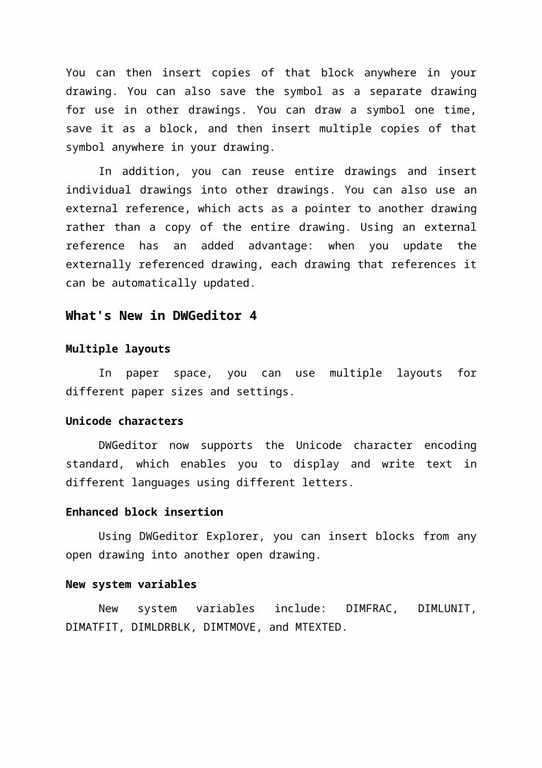
When you create a paper drawing manually, you can draw repetitive symbols by
tracing a plastic template. After you draw a symbol in DWGeditor, you can reuse that symbol
without having to redraw it. You simply save the symbol as a block. You can then insert
copies of that block anywhere in your drawing. You can also save the symbol as a separate
drawing for use in other drawings. You can draw a symbol one time, save it as a block, and
then insert multiple copies of that symbol anywhere in your drawing.
In addition, you can reuse entire drawings and insert individual drawings into other
drawings. You can also use an external reference, which acts as a pointer to another drawing
rather than a copy of the entire drawing. Using an external reference has an added advantage:
when you update the externally referenced drawing, each drawing that references it can be
automatically updated.
What's New in DWGeditor 4
Multiple layouts
In paper space, you can use multiple layouts for different paper sizes and settings.
Unicode characters
DWGeditor now supports the Unicode character encoding standard, which enables
you to display and write text in different languages using different letters.
Enhanced block insertion
Using DWGeditor Explorer, you can insert blocks from any open drawing into
another open drawing.
New system variables
New system variables include: DIMFRAC, DIMLUNIT, DIMATFIT, DIMLDRBLK,
DIMTMOVE, and MTEXTED.
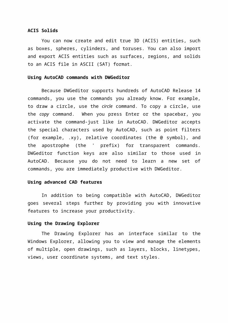
ACIS Solids
You can now create and edit true 3D (ACIS) entities, such as boxes, spheres,
cylinders, and toruses. You can also import and export ACIS entities such as surfaces,
regions, and solids to an ACIS file in ASCII (SAT) format.
Using AutoCAD commands with DWGeditor
Because DWGeditor supports hundreds of AutoCAD Release 14 commands, you use
the commands you already know. For example, to draw a circle, use the circle command. To
copy a circle, use the copy command. When you press Enter or the spacebar, you activate the
command-just like in AutoCAD. DWGeditor accepts the special characters used by
AutoCAD, such as point filters (for example, .xy), relative coordinates (the @ symbol), and
the apostrophe (the ' prefix) for transparent commands. DWGeditor function keys are also
similar to those used in AutoCAD. Because you do not need to learn a new set of commands,
you are immediately productive with DWGeditor.
Using advanced CAD features
In addition to being compatible with AutoCAD, DWGeditor goes several steps further
by providing you with innovative features to increase your productivity.
Using the Drawing Explorer
The Drawing Explorer has an interface similar to the Windows Explorer, allowing
you to view and manage the elements of multiple, open drawings, such as layers, blocks,
linetypes, views, user coordinate systems, and text styles.
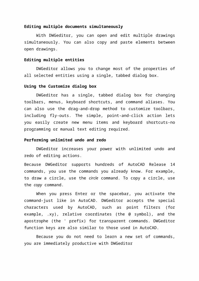
Editing multiple documents simultaneously
With DWGeditor, you can open and edit multiple drawings simultaneously. You can
also copy and paste elements between open drawings.
Editing multiple entities
DWGeditor allows you to change most of the properties of all selected entities using a
single, tabbed dialog box.
Using the Customize dialog box
DWGeditor has a single, tabbed dialog box for changing toolbars, menus, keyboard
shortcuts, and command aliases. You can also use the drag-and-drop method to customize
toolbars, including fly-outs. The simple, point-and-click action lets you easily create new
menu items and keyboard shortcuts-no programming or manual text editing required.
Performing unlimited undo and redo
DWGeditor increases your power with unlimited undo and redo of editing actions.
Because DWGeditor supports hundreds of AutoCAD Release 14 commands, you use the
commands you already know. For example, to draw a circle, use the circle command. To
copy a circle, use the copy command.
When you press Enter or the spacebar, you activate the command-just like in
AutoCAD. DWGeditor accepts the special characters used by AutoCAD, such as point filters
(for example, .xy), relative coordinates (the @ symbol), and the apostrophe (the ' prefix) for
transparent commands. DWGeditor function keys are also similar to those used in AutoCAD.
Because you do not need to learn a new set of commands, you are immediately
productive with DWGeditor
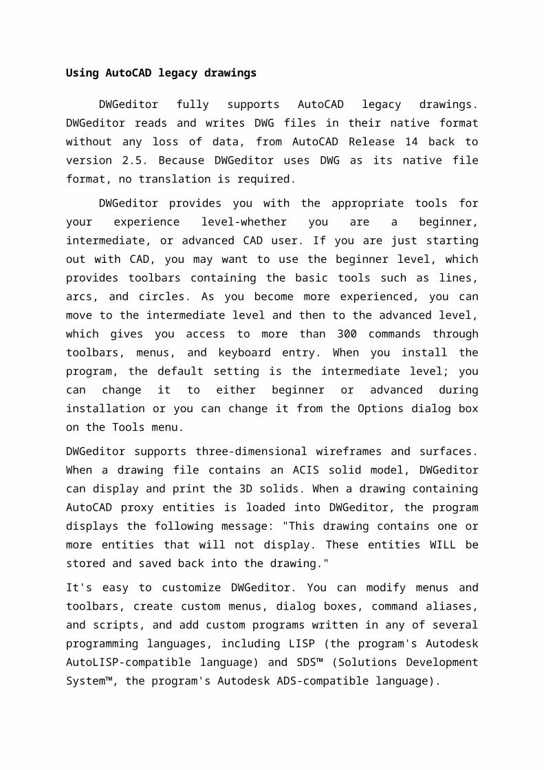
Using AutoCAD legacy drawings
DWGeditor fully supports AutoCAD legacy drawings. DWGeditor reads and writes
DWG files in their native format without any loss of data, from AutoCAD Release 14 back to
version 2.5. Because DWGeditor uses DWG as its native file format, no translation is
required.
DWGeditor provides you with the appropriate tools for your experience level-whether
you are a beginner, intermediate, or advanced CAD user. If you are just starting out with
CAD, you may want to use the beginner level, which provides toolbars containing the basic
tools such as lines, arcs, and circles. As you become more experienced, you can move to the
intermediate level and then to the advanced level, which gives you access to more than 300
commands through toolbars, menus, and keyboard entry. When you install the program, the
default setting is the intermediate level; you can change it to either beginner or advanced
during installation or you can change it from the Options dialog box on the Tools menu.
DWGeditor supports three-dimensional wireframes and surfaces. When a drawing file
contains an ACIS solid model, DWGeditor can display and print the 3D solids. When a
drawing containing AutoCAD proxy entities is loaded into DWGeditor, the program displays
the following message: "This drawing contains one or more entities that will not display.
These entities WILL be stored and saved back into the drawing."
It's easy to customize DWGeditor. You can modify menus and toolbars, create custom
menus, dialog boxes, command aliases, and scripts, and add custom programs written in any
of several programming languages, including LISP (the program's Autodesk AutoLISP-
compatible language) and SDS™ (Solutions Development System™, the program's Autodesk
ADS-compatible language).
You can run existing Autodesk AutoLISP applications in DWGeditor with little or no
modification. DWGeditor uses the appload command so you can easily load LISP programs.
DWGeditor reads files that contain dialog control language (DCL) statements as well, which
makes DWGeditor compatible with dialog boxes created for AutoCAD.
Result:
Ex.No:1(b)Study of Coordinate systemsDate:
Aim: To study of various coordinate systems in engineering Drawing.
Coordinate system
For accuracy in a drawing, you can locate specific points by entering coordinates as
you draw or modify entities. When you create two-dimensional entities, you enter two-
dimensional coordinates; for three-dimensional entities, you specify three-dimensional
coordinates. You can also specify coordinates in relation to other known locations or entities
in a drawing. In particular, when you work in three-dimensional drawings, it is often easier to
specify coordinates in relation to a two-dimensional working plane, called a user coordinate
system (UCS).
This section explains how to work with coordinates, including how to:
Use two-dimensional and three-dimensional coordinate systems.
Specify absolute and relative coordinates.
Specify polar, spherical, and cylindrical coordinates.
Define and manipulate user coordinate systems.
Using two-dimensional coordinates
When working in two dimensions, you specify points on the xy plane. You can
specify any point as an absolute coordinate (or Cartesian coordinate), using the exact x-
coordinate and y-coordinate locations in relation to the origin (the 0,0 coordinate point at
which the two axes intersect), or as a relative coordinate in relation to the previous point. You
can also specify points using relative or absolute polar coordinates, which locate a point using
a distance and an angle.
Using three-dimensional coordinates
Specifying coordinates in three-dimensional space is similar to working in two
dimensions, except that you also use the z-axis to locate coordinates. Three-dimensional
coordinates are represented in the format x,y,z (for example, 2,3,6).
Using the right-hand rule
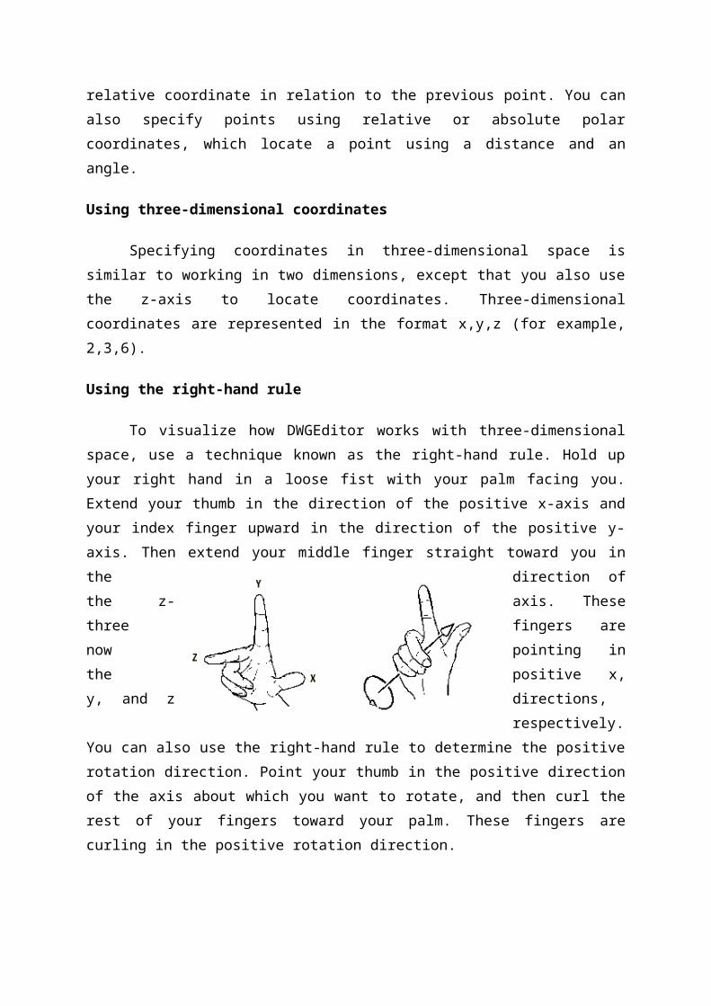
To visualize how DWGEditor works with three-dimensional space, use a technique
known as the right-hand rule. Hold up your right hand in a loose fist with your palm facing
you. Extend your thumb in the direction of the positive x-axis and your index finger upward
in the direction of the positive y-axis. Then extend your middle finger straight toward you in
the direction of the z-axis. These three fingers are now pointing in the positive x, y, and z
directions, respectively. You can also use the right-hand rule to determine the positive
rotation direction. Point your thumb in the positive direction of the axis about which you
want to rotate, and then curl the rest of your fingers toward your palm. These fingers are
curling in the positive rotation direction.
The right-hand rule helps you determine the positive direction of the x-, y-, and z-axes and
the positive rotation direction.
Entering absolute Cartesian coordinates
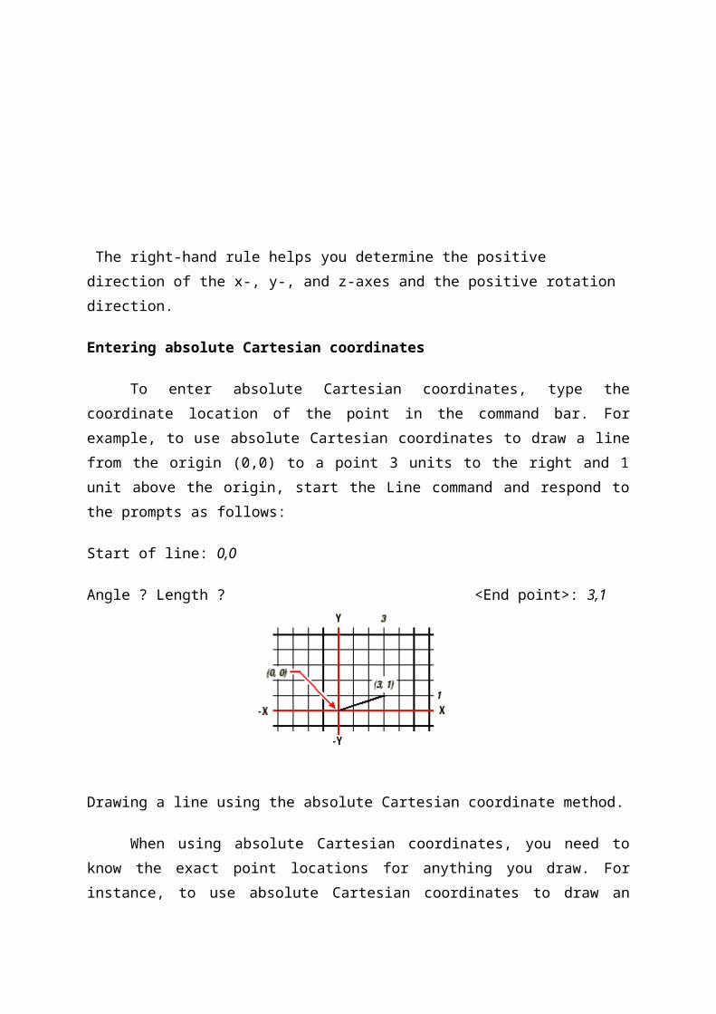
To enter absolute Cartesian coordinates, type the coordinate location of the point in
the command bar. For example, to use absolute Cartesian coordinates to draw a line from the
origin (0,0) to a point 3 units to the right and 1 unit above the origin, start the Line command
and respond to the prompts as follows:
Start of line: 0,0
Angle ? Length ? <End point>: 3,1
Drawing a line using the absolute Cartesian coordinate method.
When using absolute Cartesian coordinates, you need to know the exact point
locations for anything you draw. For instance, to use absolute Cartesian coordinates to draw
an 8.5-unit square with its lower left corner at 4,5, you must determine that the upper left
corner is at coordinate 4,13.5, the upper right corner at 12.5,13.5, and the lower right corner
at 12.5,5.
Entering polar coordinates
Using relative polar coordinates makes drawing a square tilted at a 45-degree angle a
simple task. Polar coordinates base the location of a point on a distance and angle from either
the origin (absolute coordinate) or from the previous point (relative coordinate).
To specify polar coordinates, type a distance and an angle, separated by the open
angle bracket (<). For example, to use relative polar coordinates to specify a point 1 unit
away from the previous point and at an angle of 45 degrees, type @1<45.
To draw the square from the example in the previous section, "Entering relative
Cartesian coordinates," this time tilted at a 45-degree angle, start the Line command, and then
respond to the prompts as follows:
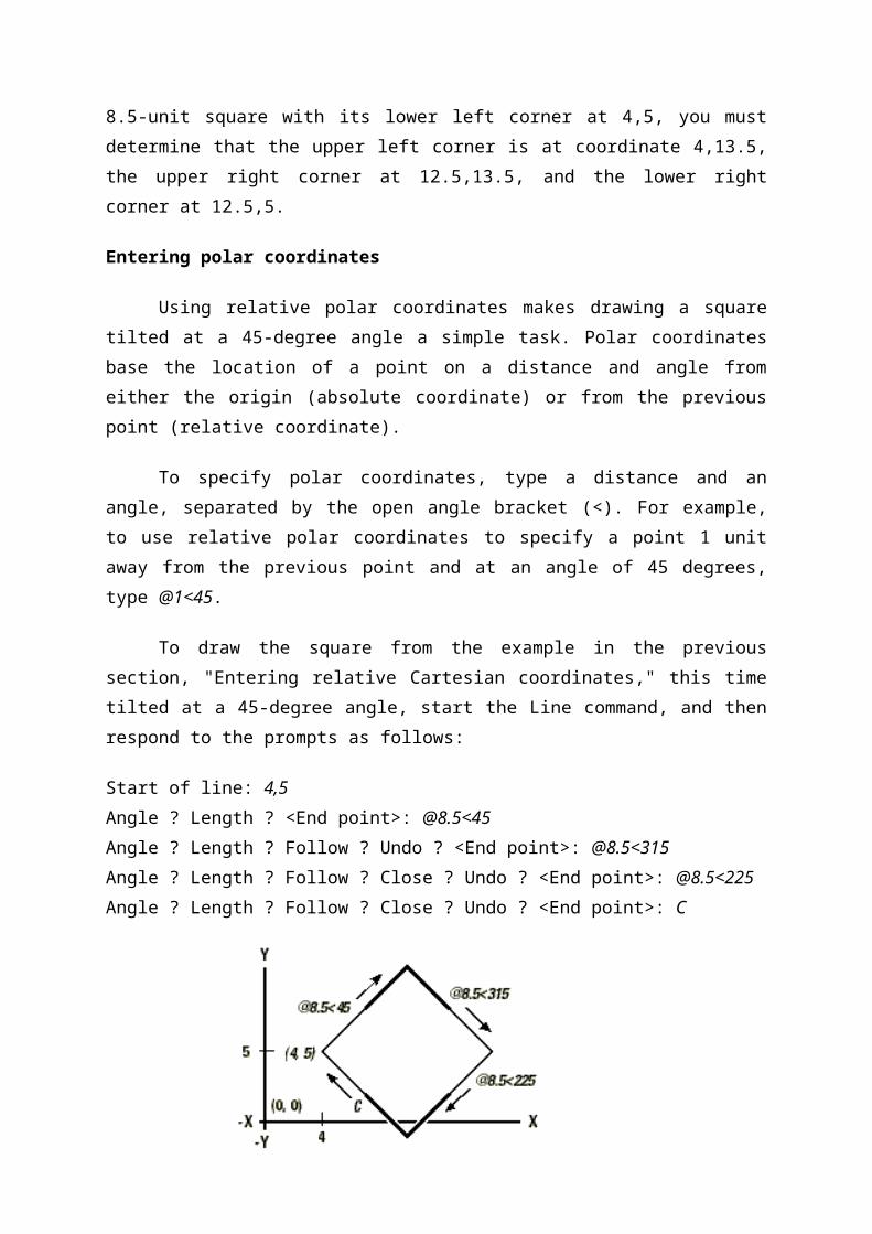
Start of line: 4,5
Angle ? Length ? <End point>: @8.5<45
Angle ? Length ? Follow ? Undo ? <End point>: @8.5<315
Angle ? Length ? Follow ? Close ? Undo ? <End point>: @8.5<225
Angle ? Length ? Follow ? Close ? Undo ? <End point>: C
Drawing a tilted square using the relative polar coordinates method; enter C to close.
NOTE: This example, like all examples in this guide, assumes the program's default settings:
Angles increase counterclockwise and decrease clockwise. Thus, an angle of 315 degrees is
the same as -45 degrees.
Entering spherical coordinates
When working in three-dimensional space, you can use spherical coordinates to
specify a three-dimensional point by entering its distance from either the origin (absolute
distance) or the last point (relative distance), along with its angle in the xy plane and its angle
up from the xy plane. In spherical format, you separate each angle with the open angle
bracket (<). Thus, to draw a line from the origin to a point 10.2500 drawing units away, at an
angle of 45 degrees from the x-axis and 35 degrees from the xy plane, start the Line
command, and then respond to the prompts as follows:
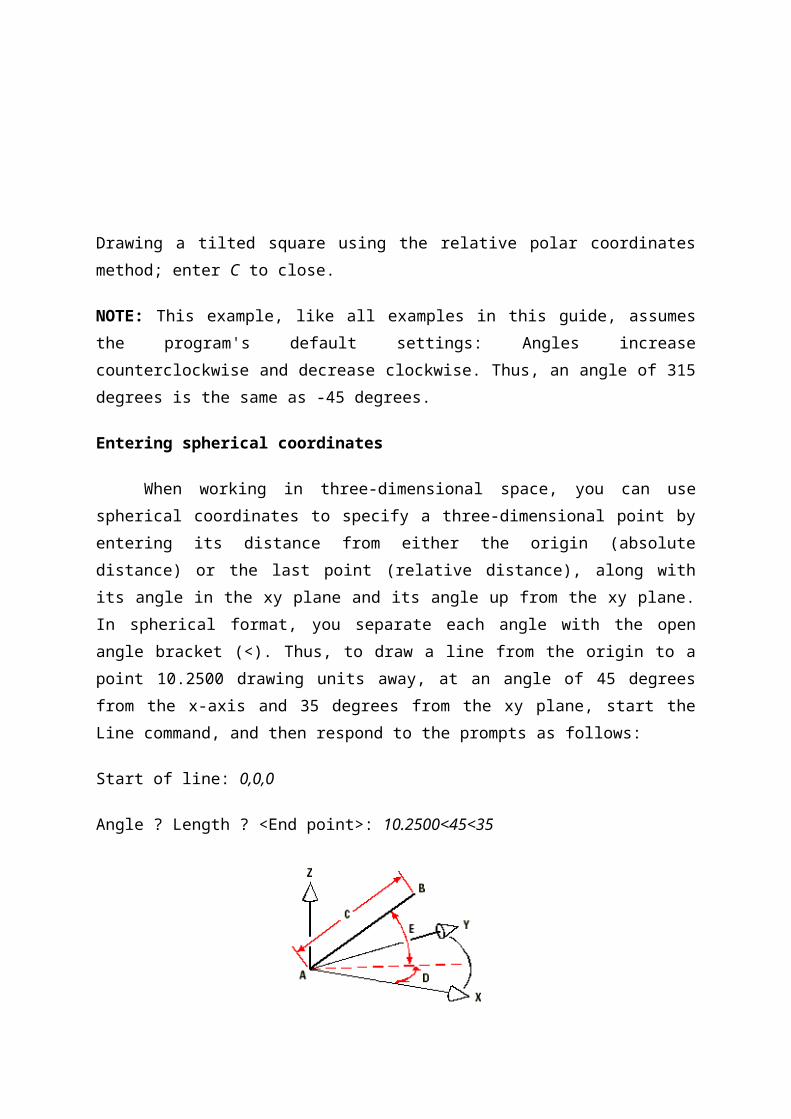
Start of line: 0,0,0
Angle ? Length ? <End point>: 10.2500<45<35
When you draw a line from a start point (A) to an endpoint (B) using spherical
coordinates, you specify its length (C, in this case 10.2500 units), the angle in the xy plane
(D, in this case 45 degrees), and the angle from the xy plane (E, in this case 35 degrees).
Entering cylindrical coordinates
When working in three-dimensional space, you can also use cylindrical coordinates to
specify a three-dimensional point. You specify a point by entering its distance from either the
origin (absolute distance) or the last point (relative distance), its angle in the xy plane, and its
z-coordinate value.In cylindrical format, you separate the distance and angle with the open
angle bracket (<) and separate the angle and z value with a comma. For example, to draw a
line from the last point to a point 7.4750 units away, at an angle of 27 degrees from the x-axis
in the xy plane and 3 units up in the z direction, start the Line command, and then respond to
the prompts as follows:
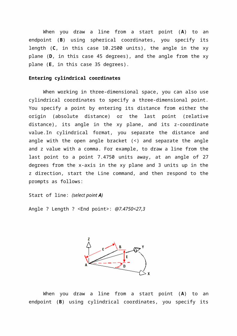
Start of line: (select point A)
Angle ? Length ? <End point>: @7.4750<27,3
When you draw a line from a start point (A) to an endpoint (B) using cylindrical
coordinates, you specify its length (C, in this case 7.4750), the angle in the xy plane (D, in
this case 27 degrees), and the distance in the z direction (E, in this case 3 units).
Defining user coordinate systems
When working in three-dimensional space, you can define a user coordinate system
(UCS) with its own 0,0,0 origin and orientation separate from the World Coordinate System.
You can create as many user coordinate systems as you want, and then save and recall them
as you need them to simplify construction of three-dimensional entities.
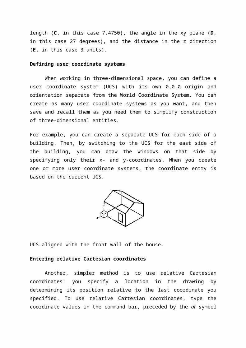
For example, you can create a separate UCS for each side of a building. Then, by switching
to the UCS for the east side of the building, you can draw the windows on that side by
specifying only their x- and y-coordinates. When you create one or more user coordinate
systems, the coordinate entry is based on the current UCS.
UCS aligned with the front wall of the house.
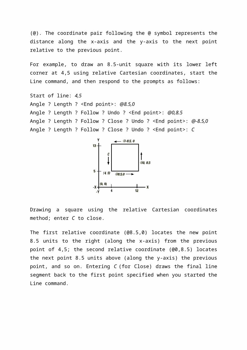
Entering relative Cartesian coordinates
Another, simpler method is to use relative Cartesian coordinates: you specify a
location in the drawing by determining its position relative to the last coordinate you
specified. To use relative Cartesian coordinates, type the coordinate values in the command
bar, preceded by the at symbol (@). The coordinate pair following the @ symbol represents
the distance along the x-axis and the y-axis to the next point relative to the previous point.
For example, to draw an 8.5-unit square with its lower left corner at 4,5 using relative
Cartesian coordinates, start the Line command, and then respond to the prompts as follows:
Start of line: 4,5
Angle ? Length ? <End point>: @8.5,0
Angle ? Length ? Follow ? Undo ? <End point>: @0,8.5
Angle ? Length ? Follow ? Close ? Undo ? <End point>: @-8.5,0
Angle ? Length ? Follow ? Close ? Undo ? <End point>: C
Drawing a square using the relative Cartesian coordinates method; enter C to close.
The first relative coordinate (@8.5,0) locates the new point 8.5 units to the right (along the x-
axis) from the previous point of 4,5; the second relative coordinate (@0,8.5) locates the next
point 8.5 units above (along the y-axis) the previous point, and so on. Entering C (for Close)
draws the final line segment back to the first point specified when you started the Line
command.
Result:
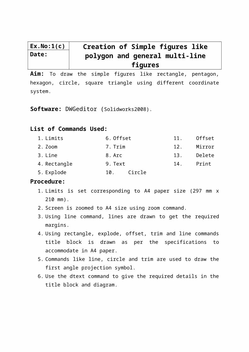
Ex.No:1(c) Creation of Simple figures like polygon and general multi-line figuresDate:
Aim: To draw the simple figures like rectangle, pentagon, hexagon, circle, square triangle
using different coordinate system.
Software: DWGeditor (Solidworks2008).
List of Commands Used:1. Limits
2. Zoom
3. Line
4. Rectangle
5. Explode
6. Offset
7. Trim
8. Arc
9. Text
10. Circle
11. Offset
12. Mirror
13. Delete
14. Print
Procedure:1. Limits is set corresponding to A4 paper size (297 mm x 210 mm).
2. Screen is zoomed to A4 size using zoom command.
3. Using line command, lines are drawn to get the required margins.
4. Using rectangle, explode, offset, trim and line commands title block is drawn as per
the specifications to accommodate in A4 paper.
5. Commands like line, circle and trim are used to draw the first angle projection
symbol.
6. Use the dtext command to give the required details in the title block and diagram.
7. Various command like line, rectangle, circle, offset, trim etc. are used to complete the
given simple figures diagram in absolute, relative Cartesian and polar coordinate
methods.
8. Use the trim and delete commands to remove any unwanted lines.
9. Use the dtext command to name the simple figures.
10. The views are printed on A4 sheet using the print command.
Result:Thus the required simple figures like rectangle, pentagon, hexagon, circle, square,
triangle are drawn using different coordinate system with the help of DWGeditor(Solid
Works2009).
Ex.No:2 Creation of Title Block with Projection symbolDate:Aim: TO create the title block with first angle projection symbol.
Software Used: Solidworks 2008.
List of Commands Used:1. Limits
2. Zoom
3. Line
4. Rectangle
5. Explode
6. Offset
7. Trim
8. Circle
9. Polygon
10. Dtext
11. Delete
12. Print
Procedure:1. Limits is set corresponding to A4 paper size (297 mm x 210 mm).
2. Screen is zoomed to A4 paper size using zoom command.
3. Using line command, lines are drawn to get the required margins.
4. Using rectangle, explodes, offset trim and line commands title block si drawn as per
the specifications.
5. Command like line, circle and trim are used to draw the first angle projection symbol.
6. Trim and delete commands are used to remove any unwanted lines.
7. The dtext command is used to give the required details in the title block.
8. The title block with first angle projection symbol is printed on A4 size sheet using the
print command.
Result:The required title block and first angle projection symbol is drawn with suitable dimensions
suing DWG Editor (Solid Works2009).
Ex.No:3 Drawing of Curves – Parabola, Involutes and SpiralDate:
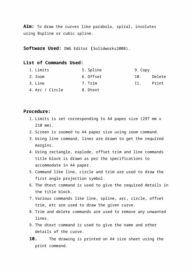
Aim: To draw the curves like parabola, spiral, involutes using Bspline or cubic spline.
Software Used: DWG Editor (Solidworks2008).
List of Commands Used:1. Limits
2. Zoom
3. Line
4. Arc / Circle
5. Spline
6. Offset
7. Trim
8. Dtext
9. Copy
10. Delete
11. Print
Procedure:1. Limits is set corresponding to A4 paper size (297 mm x 210 mm).
2. Screen is zoomed to A4 paper size using zoom command.
3. Using line command, lines are drawn to get the required margins.
4. Using rectangle, explode, offset trim and line commands title block is drawn as per
the specifications to accommodate in A4 paper.
5. Command like line, circle and trim are used to draw the first angle projection symbol.
6. The dtext command is used to give the required details in the title block.
7. Various commands like line, spline, arc, circle, offset trim, etc are used to draw the
given curve.
8. Trim and delete commands are used to remove any unwanted lines.
9. The dtext command is used to give the name and other details of the curve.
10. The drawing is printed on A4 size sheet using the print command.
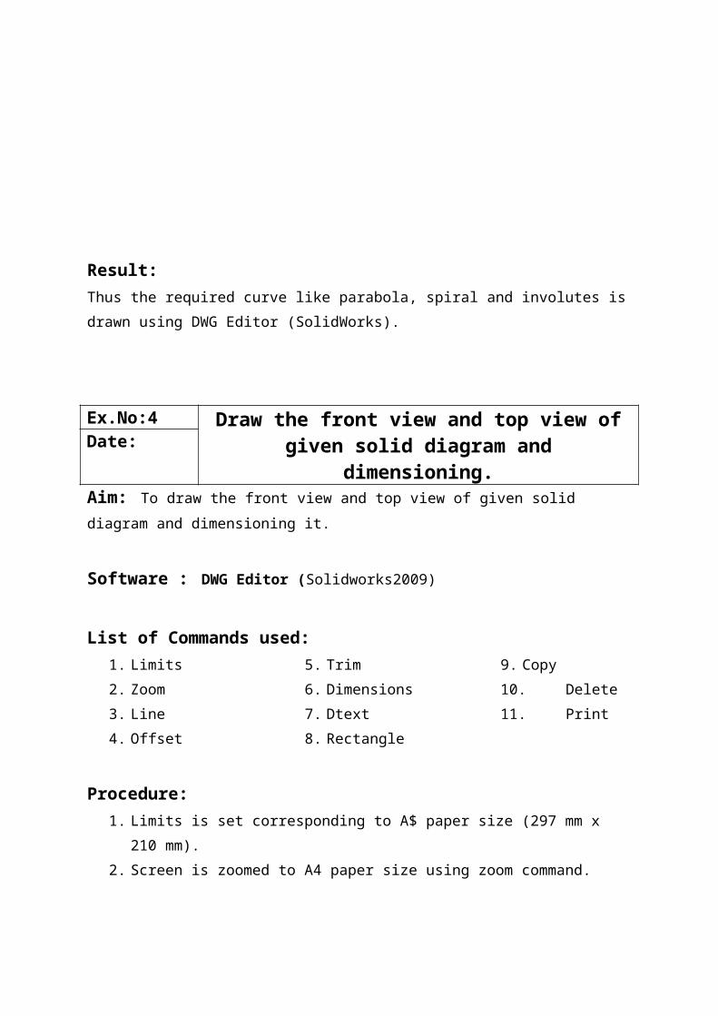
Result:Thus the required curve like parabola, spiral and involutes is drawn using DWG Editor
(SolidWorks).
Ex.No:4 Draw the front view and top view of given solid diagram and dimensioning.Date:
Aim: To draw the front view and top view of given solid diagram and dimensioning it.
Software : DWG Editor (Solidworks2009)
List of Commands used:1. Limits
2. Zoom
3. Line
4. Offset
5. Trim
6. Dimensions
7. Dtext
8. Rectangle
9. Copy
10. Delete
11. Print
Procedure:1. Limits is set corresponding to A$ paper size (297 mm x 210 mm).
2. Screen is zoomed to A4 paper size using zoom command.
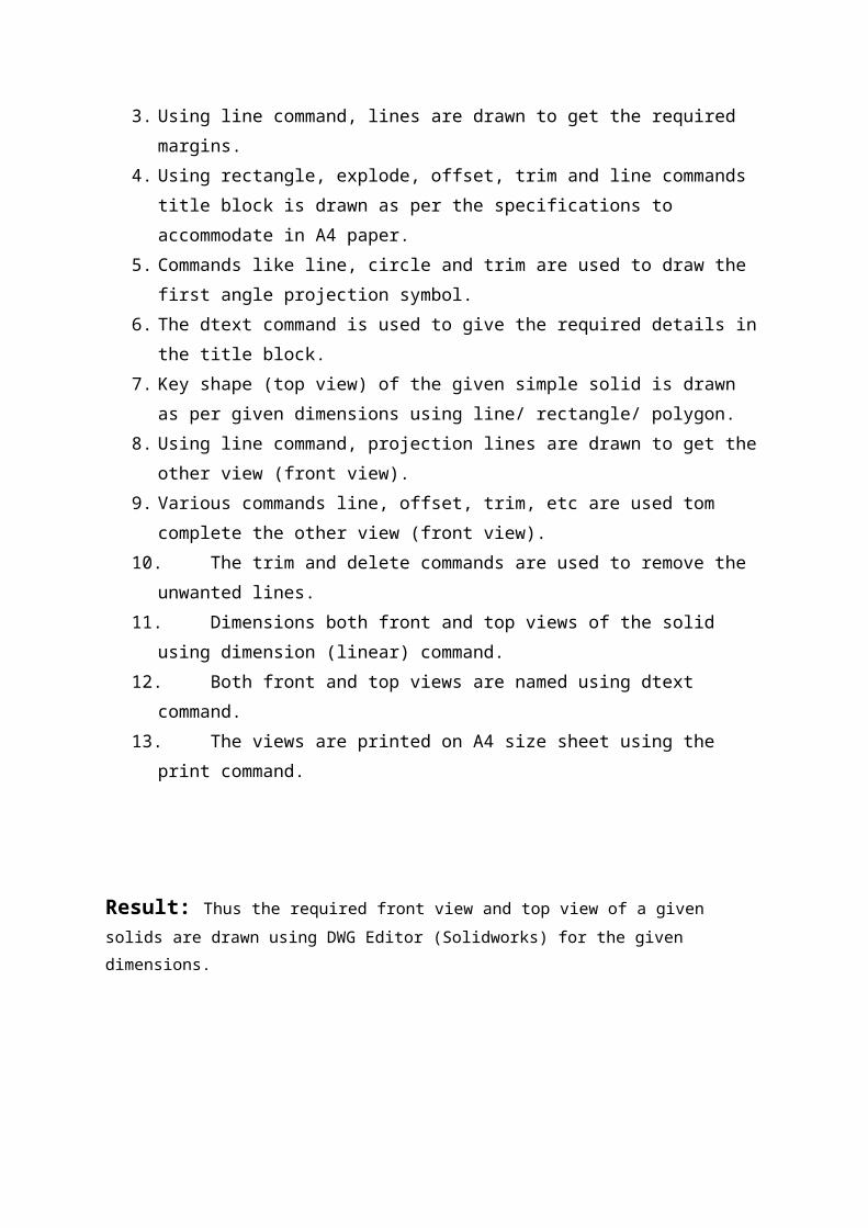
3. Using line command, lines are drawn to get the required margins.
4. Using rectangle, explode, offset, trim and line commands title block is drawn as per
the specifications to accommodate in A4 paper.
5. Commands like line, circle and trim are used to draw the first angle projection
symbol.
6. The dtext command is used to give the required details in the title block.
7. Key shape (top view) of the given simple solid is drawn as per given dimensions
using line/ rectangle/ polygon.
8. Using line command, projection lines are drawn to get the other view (front view).
9. Various commands line, offset, trim, etc are used tom complete the other view (front
view).
10. The trim and delete commands are used to remove the unwanted lines.
11. Dimensions both front and top views of the solid using dimension (linear) command.
12. Both front and top views are named using dtext command.
13. The views are printed on A4 size sheet using the print command.
Result: Thus the required front view and top view of a given solids are drawn using DWG Editor
(Solidworks) for the given dimensions.
(i).
(ii)
(iii)
(iv)

(v).
(vii).
(vi).
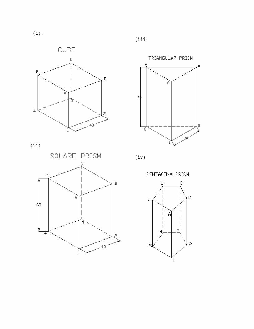
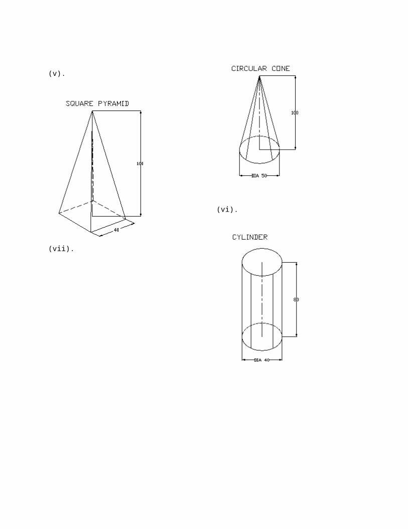
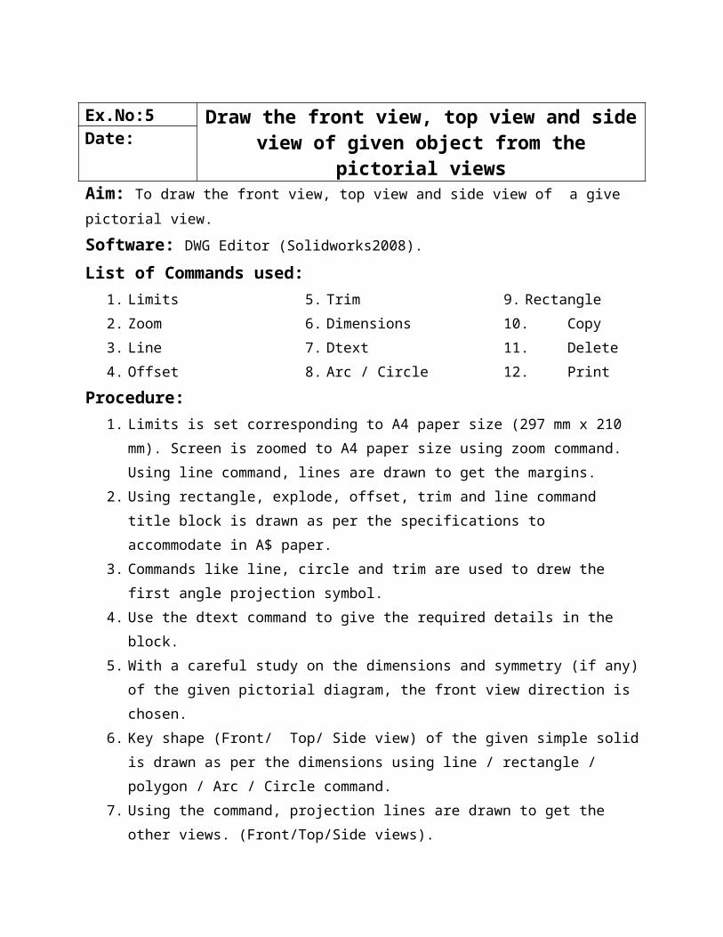
Ex.No:5
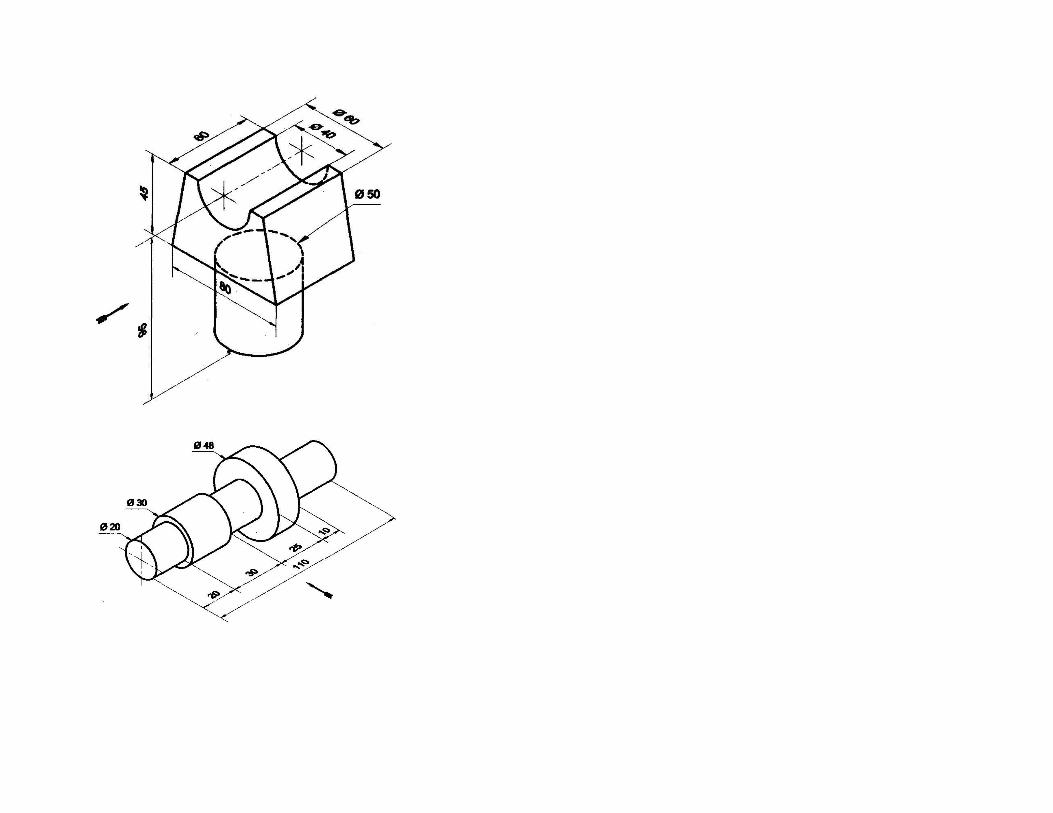
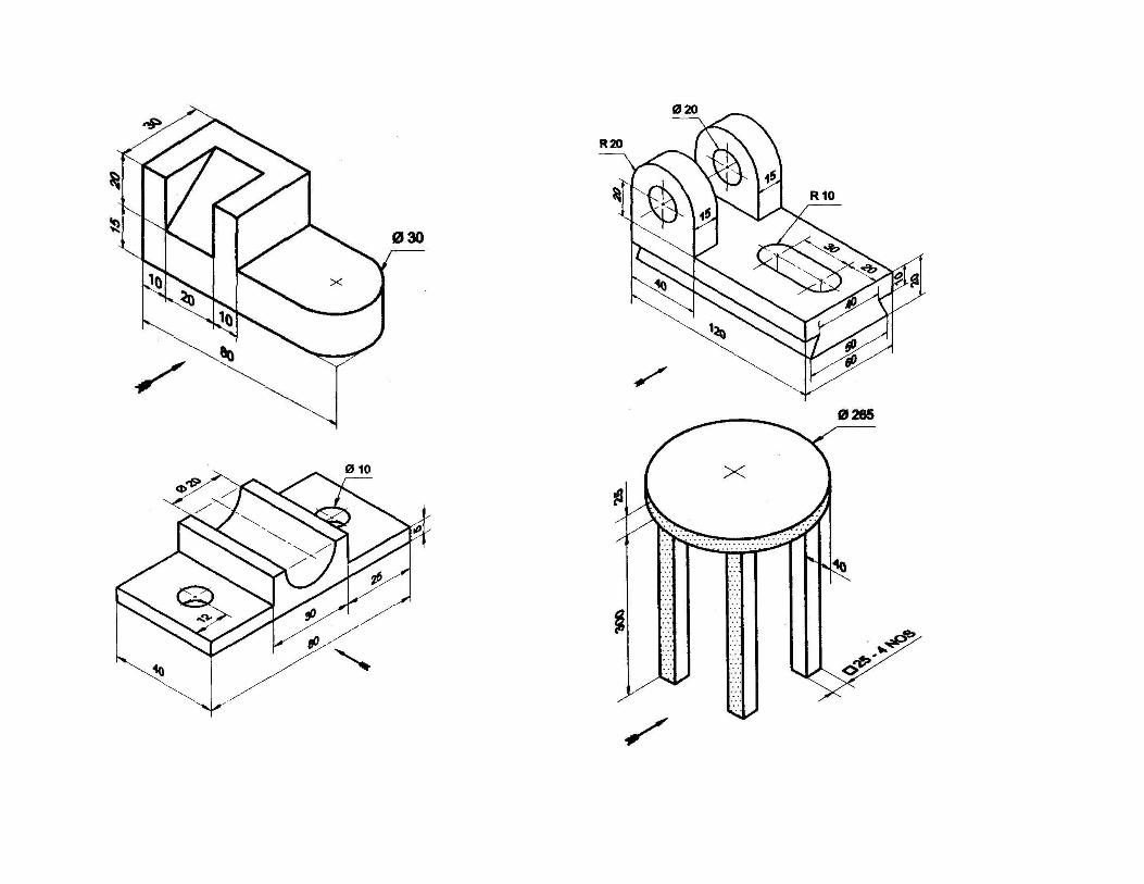
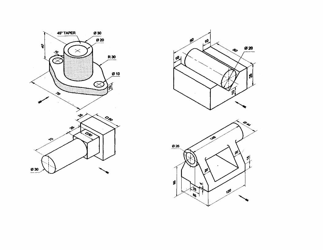
Draw the front view, top view and side view of given object from the pictorial views
Date:
Aim: To draw the front view, top view and side view of a give pictorial view.
Software: DWG Editor (Solidworks2008).
List of Commands used:1. Limits
2. Zoom
3. Line
4. Offset
5. Trim
6. Dimensions
7. Dtext
8. Arc / Circle
9. Rectangle
10. Copy
11. Delete
12. Print
Procedure:1. Limits is set corresponding to A4 paper size (297 mm x 210 mm). Screen is zoomed to
A4 paper size using zoom command. Using line command, lines are drawn to get the
margins.
2. Using rectangle, explode, offset, trim and line command title block is drawn as per the
specifications to accommodate in A$ paper.
3. Commands like line, circle and trim are used to drew the first angle projection symbol.
4. Use the dtext command to give the required details in the block.
5. With a careful study on the dimensions and symmetry (if any) of the given pictorial
diagram, the front view direction is chosen.
6. Key shape (Front/ Top/ Side view) of the given simple solid is drawn as per the
dimensions using line / rectangle / polygon / Arc / Circle command.
7. Using the command, projection lines are drawn to get the other views. (Front/Top/Side
views).
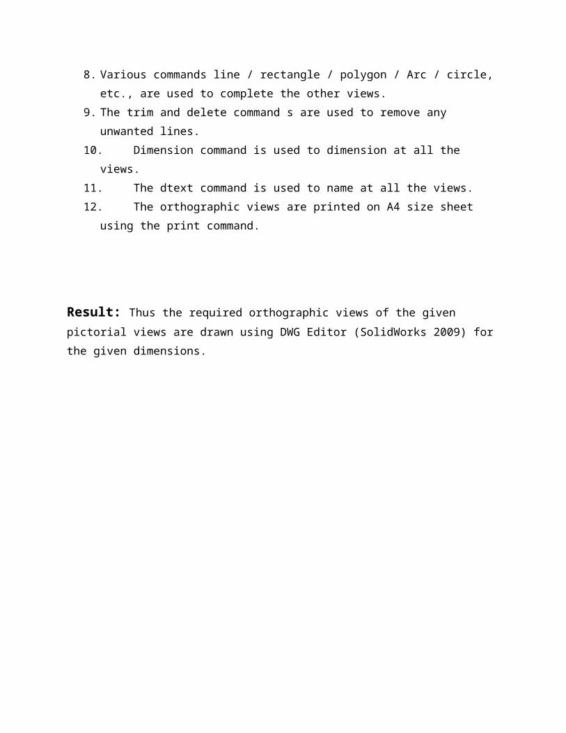
8. Various commands line / rectangle / polygon / Arc / circle, etc., are used to complete the
other views.
9. The trim and delete command s are used to remove any unwanted lines.
10. Dimension command is used to dimension at all the views.
11. The dtext command is used to name at all the views.
12. The orthographic views are printed on A4 size sheet using the print command.
Result: Thus the required orthographic views of the given pictorial views are drawn using
DWG Editor (SolidWorks 2009) for the given dimensions.
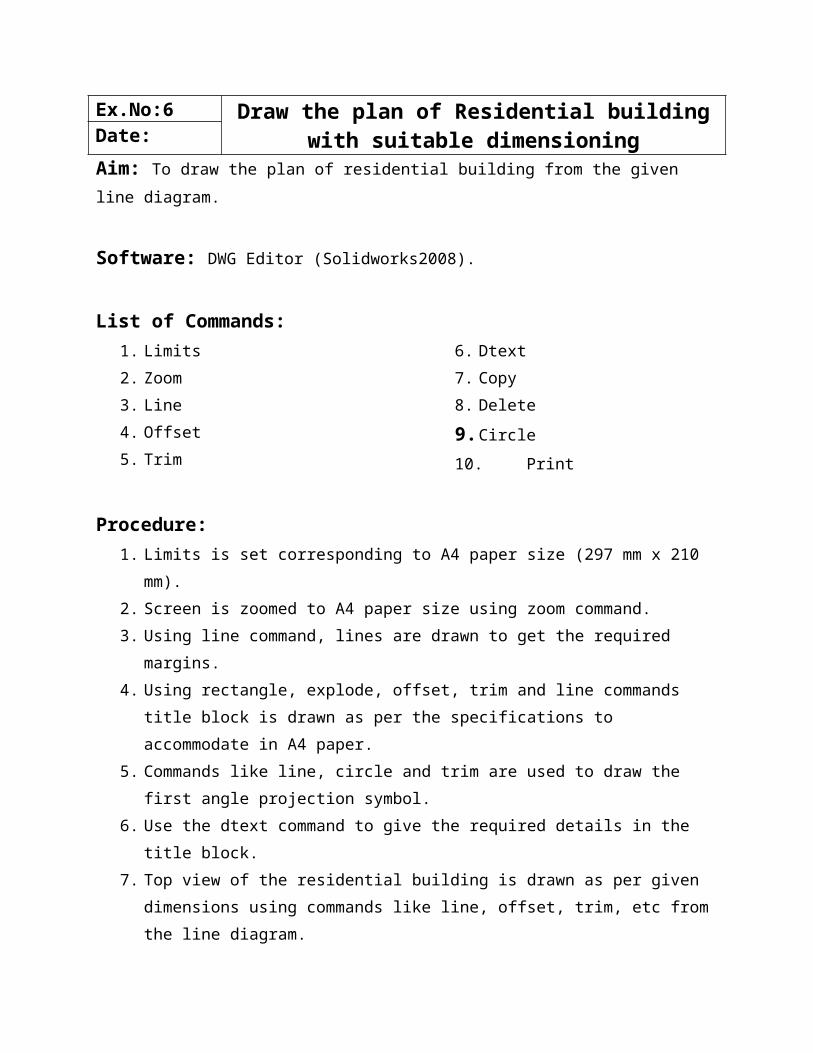
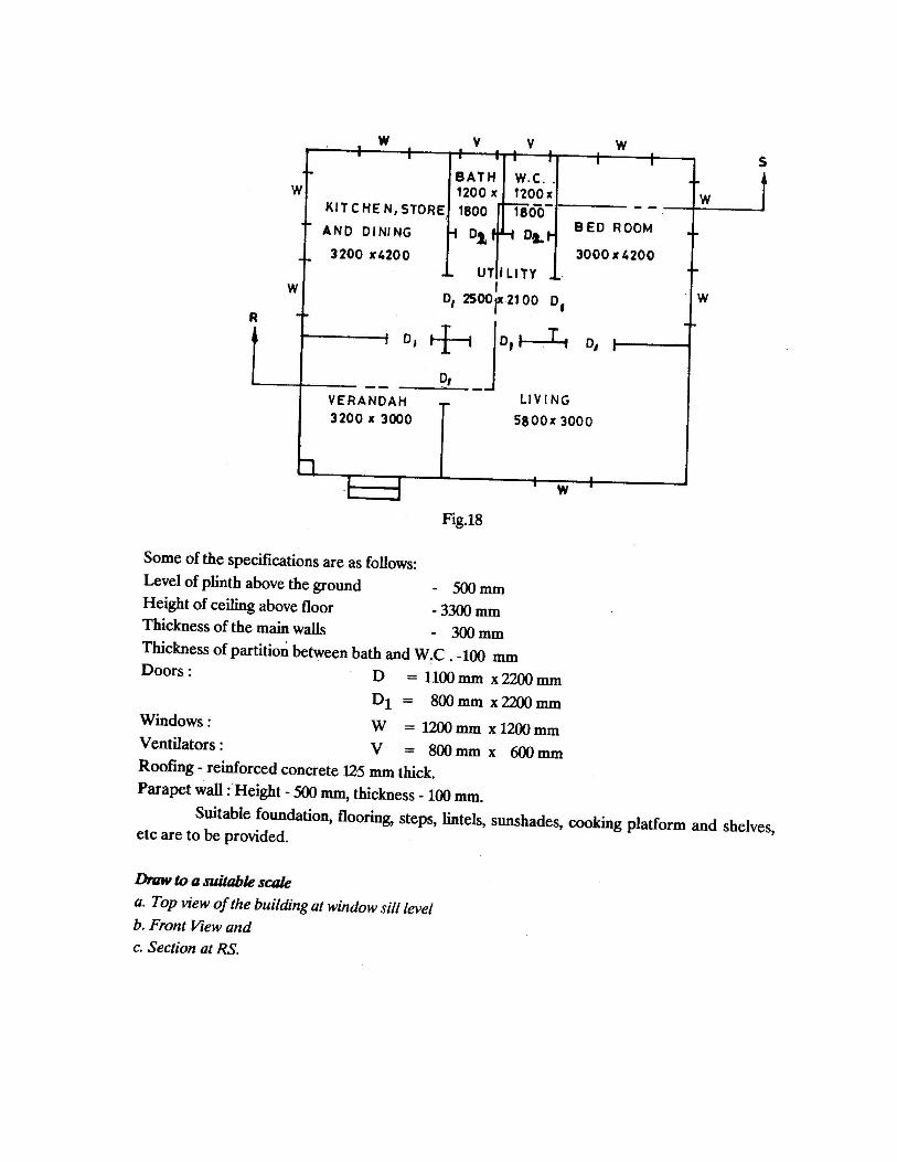
Ex.No:6 Draw the plan of Residential building with suitable dimensioningDate:
Aim: To draw the plan of residential building from the given line diagram.
Software: DWG Editor (Solidworks2008).
List of Commands:1. Limits
2. Zoom
3. Line
4. Offset
5. Trim
6. Dtext
7. Copy
8. Delete
9. Circle
10. Print
Procedure:1. Limits is set corresponding to A4 paper size (297 mm x 210 mm).
2. Screen is zoomed to A4 paper size using zoom command.
3. Using line command, lines are drawn to get the required margins.
4. Using rectangle, explode, offset, trim and line commands title block is drawn as per the
specifications to accommodate in A4 paper.
5. Commands like line, circle and trim are used to draw the first angle projection symbol.
6. Use the dtext command to give the required details in the title block.
7. Top view of the residential building is drawn as per given dimensions using commands
like line, offset, trim, etc from the line diagram.
8. Using line and copy commands doors, windows, sunshades and ventilator are drawn to
get the required size.
9. Use the trim and delete commands to remove any unwanted lines.
10. Dimensions are marked in all the rooms using dimension command.
11. Rooms are named using dtext command.
12. The views are printed on A4 size sheet using the print command.
Result:Thus the required plan of the residential building is drawn using DWG Editro (SolidWorks2009)
for the given line diagram.
Ex.No:7 DRAW A STEEL TRUSS WITH SUITABLE DIMENSIONINGDate:
Aim: To draw a steel truss from the given diagram with suitable dimensions.
Software: DWG Editor (Solidworks2008).
List of Commands:1. Limits
2. Zoom
3. Line
4. Offset
5. Trim
6. Dimension
7. Dtext
8. Copy
9. Delete
10. Circle
11. Arc
12. Mirror
13. Print
Procedure:1. Limits is set corresponding to A4 paper size (297 mm x 210 mm).
2. Screen is zoomed to A$ paper using zoom command.
3. Using line command, lines are drawn to get the required margins.
4. Using rectangle , explode, offset, trim amd line command title block is drawn as per the
specifications to accommodate in A$ paper.
5. Commands like line, circle (or) arc and trim are used to draw the first angle projection
symbol.
6. The given steel truss is drawn as per dimensions using commands like line, offset, trim,
mirror, etc are used to complete the steel truss.
7. Use the trim and delete commands to remove any unwanted lines.
8. Dimensions are marked using dimensions command.
9. Name the steel truss using dtext command.
10. The view are printed on A4 size sheet using the print command.
Result:Thus the required steel truss is drawn using DWG Editor (SolidWorks 2009) for the given steel
truss diagram.
Ex.No:8 Create a 3D model and generate 2D multiple and sectional viewsDate:
Aim: To create 3D model and generate 2D multiple and sectional views from the given pictorial
view with suitable dimensions.
Software: Solidworks2009
Procedure:1. Open the solid works software.
2. Go to file menu and choose new and then drawing.
3. First prepare the drawing sheet as per A4 format (landscape) from standard sheet size.
4. Select the sheet format foe editing.
5. Save the file in sheet format (slddrt) then close the drawing sheet window.
6. Margin is drawn using rectangle or line command, corresponding to A4 paper size
(297mm x 210).
7. Screen is zoomed to fit using zoom to fit command.
8. Using rectangle, line and trim commands title block is drawn as per the specifications to
accommodate in A4 paper.
9. Commands like line, circle and trim commands are used to draw the first angle projection
symbol.
10. Save the file as template file, then select file and save in save sheet format (slddrt) and
close the drawing window.
11. Go to file menu and choose new and then part.
12. Select any one plane (front, top and right) and draw the necessary drawing of the given
solid model in the sketcher mode using different commands by selecting icon such as
line, circle, rectangle, polygon, etc., the exit sketcher mode.
13. The drawn sketch is made to constrain by using smart dimension command.
14. Go to feature tab to choose extrude or revolved or loft command and select the feature to
be drawn to the given length.
15. In the case of pyramid or cone select feature geometry and plane (front, top, right) and
give offset distance as per the given drawing.
16. Save the object as part file format (prt).
17. Go to file menu select make drawing from part and then browse the corresponding
template file of slddrt sheet format.
18. Select the front view from the menu and place it in the sheet.
19. Project right side view, left side view and top view accordingly in the sheet as per the
first angle projection.
20. Section view is drawn by choosing view layout and section views.
21. Draw the section line as per the requirement and project the sectioned view in the
drawing sheet (use ctrl command in the key board for selecting location in A4 sheet).
22. Dimensions are marked as smart dimension command.
23. Name the all views using annotation command.
24. The views are printed on A$ size sheet using the print command.
Result:Thus the required multiple view and sectional views generate from given 3D model is
drawn using SolidWorks software.