CASTOR logging at RAL Rob Appleyard, James Adams and Kashyap Manjusha.

Manjusha Balachandran MSc : Masters Thesis Battle simulation
ૐ
Manjusha Balachandran
MSc Computer Animation 2007
Masters Thesis – Battle Simulation
September 10, 2007
Page 1

Manjusha Balachandran MSc : Masters Thesis Battle simulation
Abstract
This project has been an attempt to implement a battle scenario using Massive. It demonstrates the use of fuzzy logic in programming intelligent agent behaviours for battle simulation. It also demonstrates how each agent in the scenario uses complex battle rules to fight the opposing agent. Every team consists of two agents the tanks and the infantry. The tanks are the main elements of the battle. The infantry uses tanks as cover and when a tank is bombed the infantry seeks cover with a nearby tank.
The scenario consists of a realtime warfare scenario depicting the static warfare tactics. The battles begins with introducing the two opposing teams and ends with one of the teams getting destroyed.
Page 2

Manjusha Balachandran MSc : Masters Thesis Battle simulation
1. Introduction
1.1. The Historical and Theoretical Development of War
The human existence on earth dates back to about 8000 BC1 when, man lived a nomadic life. With the dawn of agriculture and domestication of animals, man began living a more domesticated life and this led to the development of large scale societies. With the evolution of societies there began a need for social security amongst them. This lead to the development of state governing institutions with centralized power. With the discovery of metals, man began to create weapons. All these factors contributed to an economic base which led to the emergence of warfare.
The earliest evidence of war can be dated to the 2300 BC in the kingdom of Sumer. The world’s first armies are the armies of Sumer and Egypt2.
During the wars in the ancient period, around 2300 BC, armies would force a strategic decision with a single battle. The fate of the empire turned on a single victory or defeat.
During the Iron Age, around 12th century BC the ability to remain at war increased exponentially due to the social and organizational complexities that existed. A single battle no longer decided the fate of the empires and with the increase in the military revolution the armies could draw upon the total mobilized resources of their states to support military operations.
Warfare has come a long way from its origin. Today the scene of warfare is extremely different from the battles of the past. The level of military capability and destructive power is what distinguishes modern warfare from ancient warfare. Modern warfare stresses on the usage of social, economic, and political resources of the state in support of military operations. The technological ability of target acquisition3 has been over lot of improvisations in the modern scenario.
Modern war is a war of speed, mobility, penetration, encirclement, envelopment, and, ultimately, of force annihilation4. The modern war is not a war of offense and defense but an operational level war. This operational level of war produces intense and destructive battles over shorter periods of time. Modern battles are also fought round the clock until all the objectives are achieved. All these factors have combined to produce a style of warfare that is itself qualitatively different from almost all war that has gone before.
1http://www2.hawaii.edu/~yakovee/theorigin.htm2http://www.au.af.mil/au/awc/awcgate/gabrmetz/gabr0004.htm3target acquisition is defined as detection and identification and location of a target with enough detail to permit effective weapon employment4http://www.au.af.mil/au/awc/awcgate/gabrmetz/gabr0020.htm
Page 3

Manjusha Balachandran MSc : Masters Thesis Battle simulation
1.2. Strategic and Tactics of Warfare
The rate of success of a war depends upon the Military strategy and tactics used in the war.
“Strategy can be defined as the planning level of war that is responsible for applying military means to achieve national aims; the planning level that develop war plans and theater goals”5
“Tactics is the planning level of war that deals with battle and engagement” 6
Carl Von Clausewitz the great military theorist defined "Tactics is the art of using troops in battle; strategy is the art of using battles to win the war."7
During the middle ages, strategy basically consisted of varying degrees such problems as fortification, maneuver, and supply. In the recent century given the size, training, and morale of forces, type and number of weapons available, terrain, weather, and quality and location of enemy forces, the tactics are dependent on strategic considerations.
1.2.1. The Historical and Theoretical Development of Strategy and Tactics
The historical roots of strategy and tactics date back to the origins of human warfare. The development of strategy and tactics parallels to some extent the growth, spread, and clash of civilizations; technological discoveries and refinements; and the evolution of modern state power, ideology, and nationalism.8
Different periods and places saw the use of different kinds of tactics:
Ancient Sumer (c.3000 BC) saw the existence of the dense tactical infantry formation of overlapping shields called the phalanx.
The Mediterranean region saw the dawn of modern military strategy and tactics. This period emphasized tactics like planning, keeping open lines of communication and supply, security, relentless pursuit of foes, and the use of surprise.
The Chinese military general, Sun Tzu (544 BC to 496 BC), he wrote the earliest and still the most revered military treatise in the world In it he outlines the importance of war for the state. He developed 5 governing factors of war: The Moral Law, Heaven,
5The Art of Maneuver, Pg 76 The Art of Maneuver, Pg 97http://www.molossia.org/milacademy/strategy.html8http://www.molossia.org/milacademy/strategy.html
Page 4
Manjusha Balachandran MSc : Masters Thesis Battle simulation
Earth, The Commander, and Method and Discipline9; in addition to 13 rules for warfare. Using these factors, one can determine who will win a battle and who will lose. Another important idea he developed was the notion that “All warfare is based on deception.”
In the middle ages the tactics emphasized on defensive fortifications, siege craft, and armored cavalry. With the introduction of developments like crossbow, longbow, halberd, pike, gunpowder the way war was conducted was revolutionized.
Gustav II Adolf, king of Sweden (r. 161132), is called the father of modern tactics because he reintroduced maneuver into military science. With Napoleon I, the age of modern warfare was born where battles were characterized with skirmishing and cannonading acts.10
The technological advances of the 19th century altered the scope of tactics and strategy. The volume, reach, and speed of mobilization of the warfare increased. Many technical devices like machine gun, the tank, the airplane, the submarine were used for mechanized warfare. Further the development of nuclear weapons revolutionized warfare.
1.2.2. Strategic and Tactical Principles of Warfare
The most common Strategic and Tactical Principles of warfare are: the objective, the offensive, surprise, security, unity of command, economy of force, mass, and maneuver. Most of these principles are interdependent.
Every military force has a clear objective. The offensive operations allow the choice of objectives; increases the possibility of surprise (stealth and deception) and security (protection against being surprised by enemy or losing the possibility of surprising the enemy). Unity of command, or cooperation, is essential to the pursuit of objectives, the ability to use all forces effectively (economy of force), and the concentration of superior force at a critical point (mass). Maneuver consists of the various ways in which troops can be deployed and moved to obtain offensive, mass, and surprise.
The different types of maneuver are: Offensive maneuver, ie. Penetration11 and envelopment12
9refer to http://www.sonshi.com/learn.html for more information regarding these individual factors10refer to http://www.molossia.org/milacademy/strategy.html for more information11penetration is one of the oldest maneuvers. It is a main attack that attempts to pierce the enemy line while secondary attacks up and down the enemy line prevent the freeing of the enemy reserves. 12envelopment is a maneuver in which a secondary attack attempts to hold the enemy's center while one (single envelopment) or both flanks (double envelopment) of the enemy are attacked or
Page 5
Manjusha Balachandran MSc : Masters Thesis Battle simulation
Defensiveoffensive maneuvers13
Turning movements14.
1.2.3. Tank Tactics
Tanks were first introduced in World War I15, but were clumsy and dependent on infantry. The role of those tanks was limited to support infantry charges. This tactic proved very effective, as the tanks could knock out the machine gun nests that plagued the infantry while the infantry could provide cover for the tanks in the probable event of a mechanical breakdown or in case the tank got stuck in rough terrain.
To ensure that the tanks could best support the infantry and vice versa, the tanks were spread out among infantry divisions, often in groups of three tanks. These groups, called "penny packets"
Tanks were employed in static warfare16 , trench warfare17 as well as mobile warfare18.
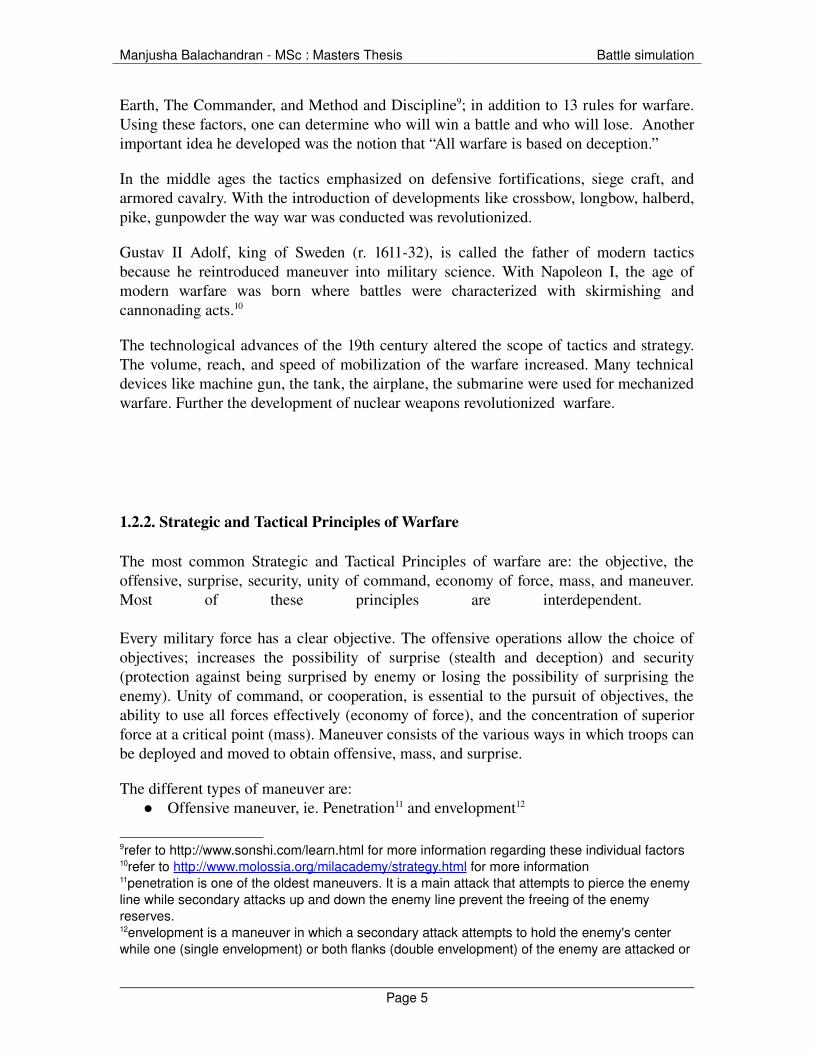
Figure 119 : The representation for Artillery, tank and Infantry. (This representation is used in figures below.)
overlapped in a push to the enemy's rear in order to threaten the enemy's communications and line of retreat. This forces the enemy to fight in several directions and possibly be destroyed in position. New variations include vertical envelopments (Airborne Troops or air mobile troops) and amphibious envelopments. 13Defensiveoffensive maneuvers include attack from a strong defensive position after the attacking enemy has exhausted in strength. 14Turning maneuvers are indirect approaches that attempt to swing wide around an enemy's flank to threaten enemy's supply and communication line. As a result, the enemy is forced to abandon a strong position or be cut off and encircled. 15http://www.tqnyc.org/NYC073871/static_warfare_ex3.htm16 static warfare consists of two opposing sides sending waves of infantry and tanks at the other side until one side runs out of troops and supplies.17 In trench warfare each side fortifies their position before moving on to attack the opposition.18 Mobile warfare is a very fast, but complicated kind of warfare.19 http://www.tqnyc.org/NYC073871/static_warfare_ex1.htm
Page 6

Manjusha Balachandran MSc : Masters Thesis Battle simulation
1.2.3.1. Static warfare20
1.2.3.1.1. Original troop deployment
Figure 221 : Tanks are spread out amongst the infantry, and supporting artillery is spread so that the entire opposing line of infantry can be targeted and the infantry has a wide bandwidth to attack enemy troops.
1.2.3.1.2. Attack movements
Figure 322 : When the attacks begin infantry and tanks attempt to overrun the enemy's defenses. More often than not, the enormous bonuses of defending rather than attacking result in the attackers being beaten back.
20 Refer to http://www.tqnyc.org/NYC073871/static_warfare_ex1.htm for more information21http://www.tqnyc.org/NYC073871/static_warfare_ex1.htm22http://www.tqnyc.org/NYC073871/mobile_warfare_ex2.htm
Page 7
Manjusha Balachandran MSc : Masters Thesis Battle simulation
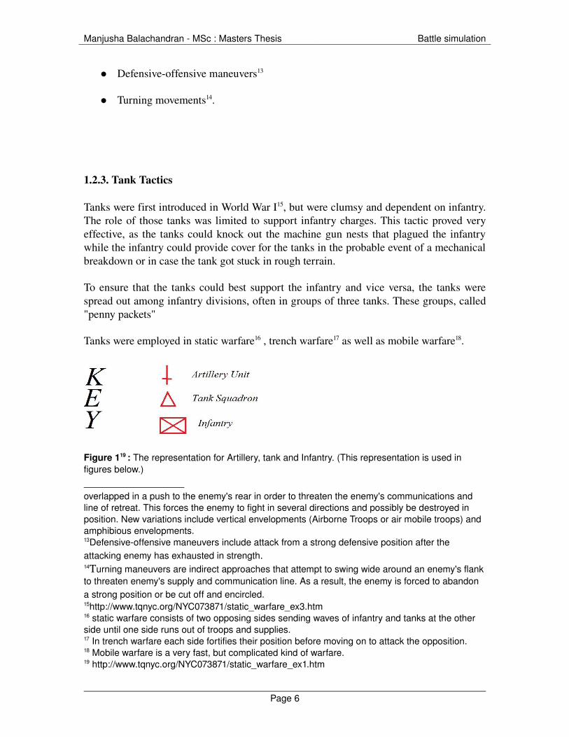
When the attacks begin infantry and tanks attempt to overrun the enemy's defenses. More often than not, the enormous bonuses of defending rather than attacking result in the attackers being beaten back.
Figure 423 : Having successfully beaten off the attacker's initial assault, the defenders (green) attempt an assault of their own. Having repelled green's assault, red might go on the offensive and so on and so forth. This may continue for months till one side runs out of enemys
1.2.3.2. Mobile warfare24
In mobile warfare, the tanks were not scattered among the infantry. Instead, the tanks would be grouped into a formation, called a panzer division. The factors which play a major role in mobile warfare essence of the entire division are range, speed, and cross country mobility.
23http://www.tqnyc.org/NYC073871/mobile_warfare_ex2.htm24 refer to http://www.tqnyc.org/NYC073871/mobile_warfare_ex2.htm#1 for more information
Page 8
Manjusha Balachandran MSc : Masters Thesis Battle simulation
1.2.3.2.1. Deployment
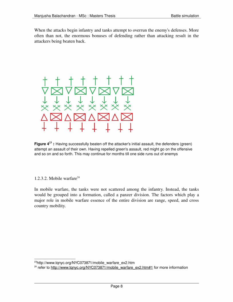
Figure 525: The troop deployment here is offensive in nature Red has grouped all of its tanks and artillery into one massive super while the infantry have been dug in.
Green has assumed the normal static formation. While green's troops are not particularly strong in any one point, they are at least equally ready for an attack on any part of the line.
1.2.3.2.2. Attack phase
Phase 1
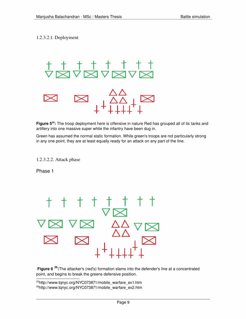
Figure 6 26:The attacker's (red's) formation slams into the defender's line at a concentrated point, and begins to break the greens defensive position.
25http://www.tqnyc.org/NYC073871/mobile_warfare_ex1.htm26http://www.tqnyc.org/NYC073871/mobile_warfare_ex2.htm
Page 9

Manjusha Balachandran MSc : Masters Thesis Battle simulation
Phase 2
Figure 7 27: Under the weight of the massive and fast moving tank assault, the defense breaks in the assaulted area.
Phase 3
Figure 8 28: Having effectively punched a hole through green's line of defense, red's tanks now fan out behind green, cutting off supply lines and lines of communication.
27http://www.tqnyc.org/NYC073871/mobile_warfare_ex2.htm28http://www.tqnyc.org/NYC073871/mobile_warfare_ex2.htm
Page 10
Manjusha Balachandran MSc : Masters Thesis Battle simulation
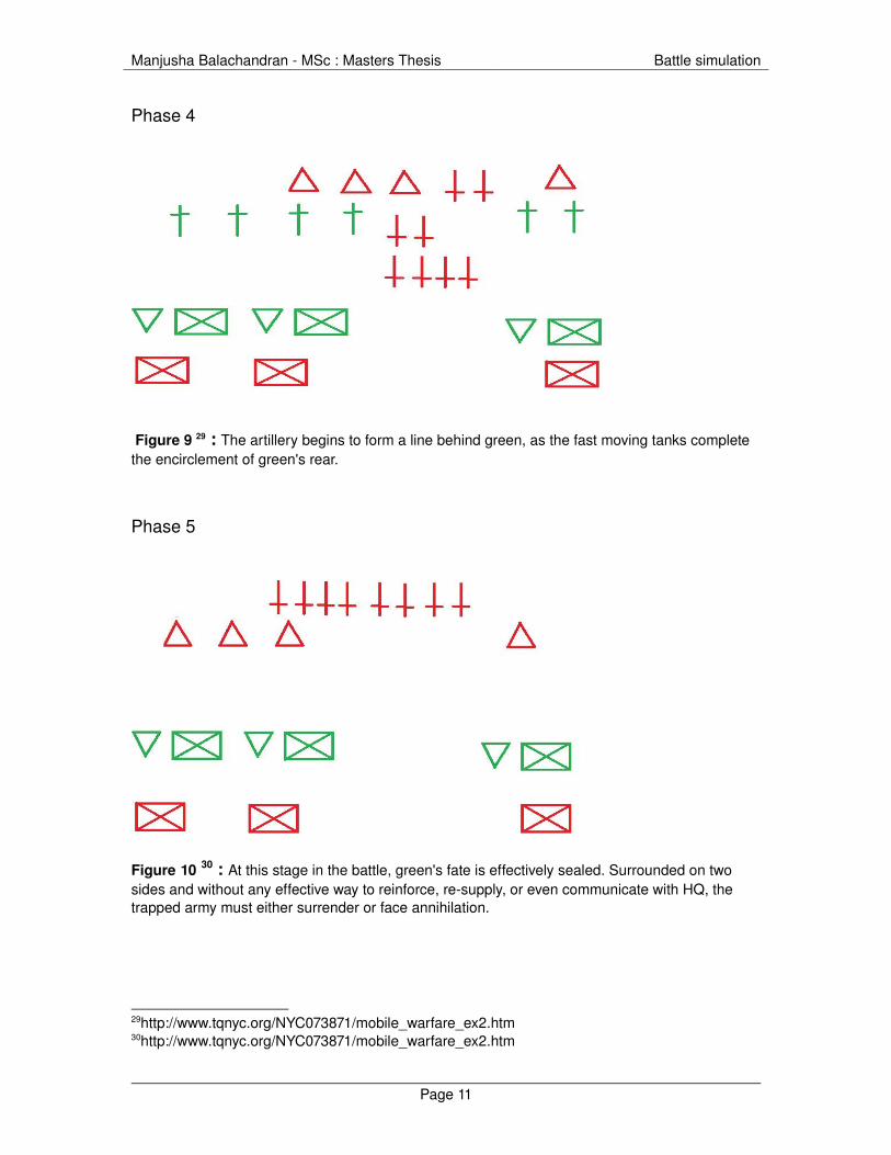
Phase 4
Figure 9 29 : The artillery begins to form a line behind green, as the fast moving tanks complete the encirclement of green's rear.
Phase 5
Figure 10 30 : At this stage in the battle, green's fate is effectively sealed. Surrounded on two sides and without any effective way to reinforce, resupply, or even communicate with HQ, the trapped army must either surrender or face annihilation.
29http://www.tqnyc.org/NYC073871/mobile_warfare_ex2.htm30http://www.tqnyc.org/NYC073871/mobile_warfare_ex2.htm
Page 11

Manjusha Balachandran MSc : Masters Thesis Battle simulation
1.2.4. Infantry tactics
The most important infantry tactics are as follows
1.2.4.1. Infantry movement over open ground
Figure 11 31: The different positions of the infantry movement
While the infantry is moving on the ground it has to ensure its safety which is generally done by making them as small a target as possible. A standing soldier is a much larger target than a laying or crouching one.The importance of making a smaller target is to force the enemy to make an accurate shot. The lying down position is good when the target size is concerned as it is the smallest but from a movement perspective it is not good to crawl on the ground as the speed of the infantry decreases. The movement position in terms of speed and smallest target is the crouched position. While moving from one place to another the infantry should move from cover32 to cover and in a zigzag pattern so that it becomes harder for the enemy to get an accurate shot of the person.
1.2.4.2. Flanking
Flanking refers to your side. The infantry must flank generally the sides and rear of the enemy as they form the most vulnerable points in the defensive positions.
31http://www.ladygamers.com/guides/basictactics.pdf32Cover is anything that hides and offers protection to the infantry such as, a brick wall, building, or a car.
Page 12

Manjusha Balachandran MSc : Masters Thesis Battle simulation
Figure 12 33: Here the red represents the enemy. The blue infantry flanks over from the sides
1.2.4.3. SilhouetteThe infantry must try and blend into the environment. It must place itself in areas that are harder for the enemy to see as well as spot where the infantry blend perfectly into the environment. If the infantry cannot blend into the environment then it has to make itself as indistinguishable from the environment as possible.
Figure 13 34: Here it is very easy to spot the person, as he is distinctively visible with the snow background. This could be a very dangerous position for the infantry.
33http://www.ladygamers.com/guides/basictactics.pdf34http://www.ladygamers.com/guides/basictactics.pdf
Page 13

Manjusha Balachandran MSc : Masters Thesis Battle simulation
Figure 14 35: Here the infantry has placed itself in a location where it is hardly impossible for it to be noticed.
The other infantry tactics are36: ● To deploy, forward.● To deploy, by the flank,● To extend intervals.● To close intervals.● To relieve skirmishers● To advance in line.● To retreat in line.● To march by the flank.● To fire, marching.● The rally.● The assembly.● To deploy a battalion, as skirmishers.● To rally the battalion, deployed as skirmishers.
35http://www.ladygamers.com/guides/basictactics.pdf36refer to http://home.att.net/%7ECap1MD/ScottSkirm.htm#A1ExInt for more information regarding the infantry tactics
Page 14
Manjusha Balachandran MSc : Masters Thesis Battle simulation
1.3. History of war simulation and gaming
This is based on an article by Colonel Wilbur Gray on the history of war gaming37.
Over the years, war games have evolved from games initially played for pleasure. The first war game was WeiHai ("encirclement"), a Chinese game which is also known as Go. In India a similar game was devised called the Indian Chaturanga. The game of chess was developed from this game which depicted armed combat. There were several other games developed on the model of chess.
In the year 1811 a Prussian fatherson team created their own version of the war game which became a rage during that period.
In 1876 war gaming was introduced as a part of the curriculum in the US Naval War College, established by William McCarty Little. He also produced a game called the ShiponShip which was a very complex tactical and strategic.
The birth of the modern hobby war games can be traced to the publication of the book Little Wars: A Game for Boys from Twelve Years to One Hundred and Fifty and for that More Intelligent Sort of Girl Who Likes Games and Books in 1913 by noted British science fiction author H.G. Wells, termed as the father of modern hobby war gaming. His strategy of gaming had simplistic rules with inexpensive mass produced toy soldiers. This made war gaming available to layman and no more limited to professional soldiers or the rich.
In 1953, the introduction of a cardboard and paper war game called Tactics by Robert from Baltimore brought a revolution in the field of commercial war gaming. In 1969, the publication of Strategy & Tactics by Christopher Wagner and later by James Dunnigan was another significant event in the evolution of commercial hobby war gaming.
Board war games had their fair demand till the 1980’s till technological versions of these games took over with the introduction of personal computers. The computer games were preferred due to their relevant advantages over the board games.
37 http://www.nhmgs.org/articles/historyofwargaming.html
Page 15

Manjusha Balachandran MSc : Masters Thesis Battle simulation
1.4. Designing Computer War Games
Every war game designed is based on the following aspects38.
Terrain39
Order of Battle40
Attrition41
Terrain Effects42
Victory Conditions43
Supply44
Artificial Intelligence Capability45
Scenario 46
The manual model does not translate directly to an automated version. Algorithms are used to create some adjustments and design modifications must be used.
1.4.1. The basic considerations of the algorithm
1.4.1.1 Positioning on terrain
The x,y,z coordinates system is used.
38 refer to http://www.hyw.com/Books/WargamesHandbook/71spec.htm for more information39 the terrain can vary from being a simple cell structure to 3D complex structures40 order of battle consists of consists of the list of units to be used in the model and the capabilities they need for interaction with the other elements of the model.41 Attrition consists of combat rules.42 Terrain effects consists of consists of effects of terrain on units and the interaction of the units with the terrain43 victory conditions specify the specifies the goals of units or groups of units.44 Suppy consists of the consummation of various units45 AI consists of consists of the rules for unit behavior, SOP's (Standard Operating Procedure) for combat and movement. Command control and panic for various units, Leadership behavior, etc.46 scenario represents the interaction of all these elements in different conditions
Page 16
Manjusha Balachandran MSc : Masters Thesis Battle simulation
1.4.1.2. Combat activity
The combat activity consists of the following:
Detect Sensors are used to determine if enemy forces are present and/or within range of weapons.
Check for Damage The damage can be caused by an enemy or from operational causes. Damages results in the physical47 and the psychological48 effects.
Fire or Flee System analyzes the situation.
If logic, or psychological effects the system withdraws from combat. Otherwise, it continues.
Repeat Above: To continue the simulation until end of time period allotted for operations, or victory conditions specify ending operations.
1.4.1.3. Victory calculationIt has to be done continuously and with great accuracy.
1.4.1.4. Scenario Deployment to rapidly explore many aspects of the simulation
1.4.1.5. Scenario GenerationUsing a library of scenario building blocks (maps, unit organizations, doctrinal
SOP’s (Standard Operating Procedure), etc.) the user can quickly build new scenarios or edit existing ones.
1.4.1.6. User Reports
These are used to provide the user with necessary information.
47 Physical Effects deal with the degradation of system performance.48 Psychological Effects deals with modifying troops to continue operations.
Page 17
Manjusha Balachandran MSc : Masters Thesis Battle simulation
1.4.2. Artificial Intelligence in War games
These are the routines which consist of complex rules that enables realistic battle simulations.
Doctrine is what drives AI; they are standard procedures that armed forces use when in combat. There are always deviations in the troop behavior when compared to what is there in the doctrine. This is due to the limitations of converting all theory into practice.49
49 Refer to http://www.hyw.com/Books/WargamesHandbook/74ai.htm for more information
Page 18

Manjusha Balachandran MSc : Masters Thesis Battle simulation
2. Previous work
A lot of research and development has gone into the simulation of warfare. Several analytical models and generic algorithms have been used to simulate the same. One such model used is the “monte carlo” model of tank battle simulation which provides a higher accuracy when compared to the other models.
This model was designed in cooperation with G. Franzen, P.O Nilsson, captain S Reinodt and G Weibull50.
The scope of the model has been limited to the following
1. Every tank fights from the same position during the whole battle.2. Movements of the tanks are taken into account during the initial phase3. The units are permitted to show as much as themselves as they wish during the
battle.4. The fight time t is calculated according to the equal interval method51
This model was programmed in FORTRAN II for IBM 7090. The program has the following features
1. The program can handle up to 15 units on each side and is contained in the core storage of the computer
2. Input data is read in as 97 data groups, constituting approximately 100 values3. The computer time is 0.3 min/play with 15 units against 94. The required accuracy in the output calls for 50 plays/game.5. The total running time is 15 min/game.
The properties of the unit are as follows.
1. In the simulation each state of the unit is assigned a notation which represents the state of the unit. Depending on the state of the unit various activities are assigned to the unit. The different states of the unit are as follows: Undamaged , Able to shoot only , Able to move only, Shocked , Out of action
2. The probability of discovery of a tank
The algorithm is as follows
50A monte carlo model for simulation of tank battles 51 All decisions and computations are performed at each step for current value of t.
Page 19
Manjusha Balachandran MSc : Masters Thesis Battle simulation
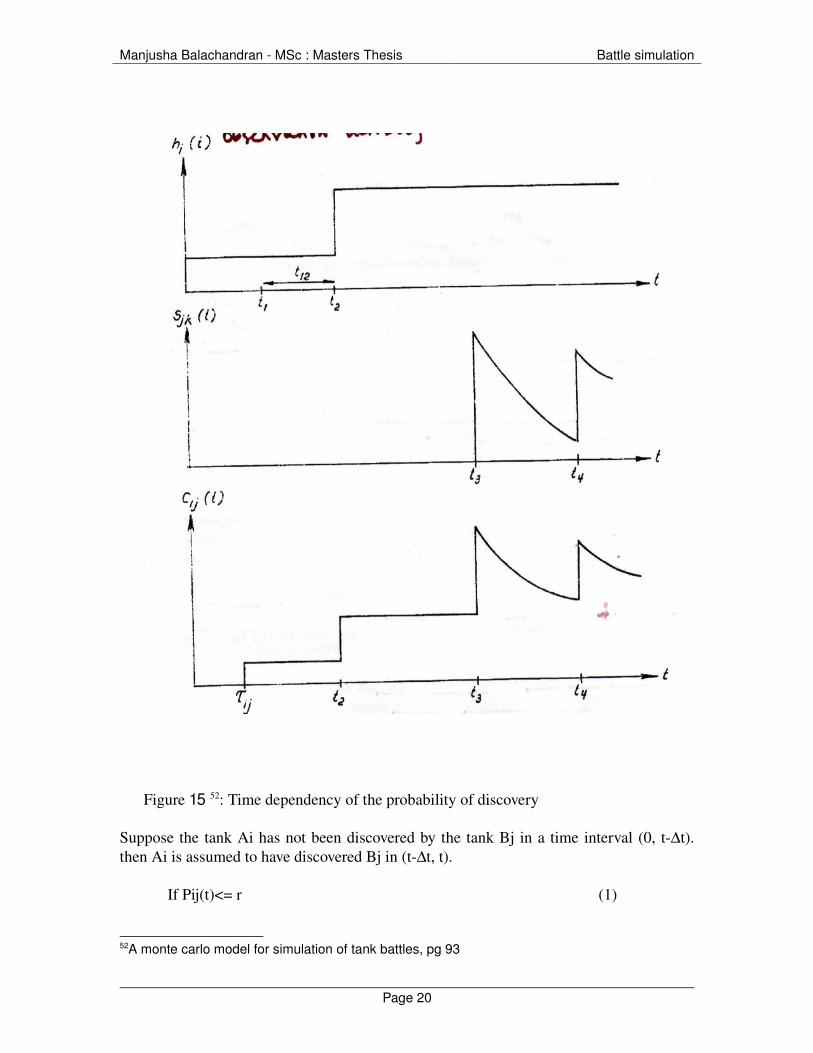
Figure 15 52: Time dependency of the probability of discovery
Suppose the tank Ai has not been discovered by the tank Bj in a time interval (0, t∆t). then Ai is assumed to have discovered Bj in (t∆t, t).
If Pij(t)<= r (1)
52A monte carlo model for simulation of tank battles, pg 93
Page 20

Manjusha Balachandran MSc : Masters Thesis Battle simulation
Where
r is the sample from rectuangular distribution R(0,1)
Pij(t) = Cij(t) ∆t
Cij(t)=(gij(t)(hi(t) + Sjk(t))kj) / dij (2)
The time dependence of Cij is expained in connection with fig 15
Gij(t)= 0 when t< τij
1 when t >= τij
Where
τij is the time when free visibility arises between Ai and Bj.
Hi(t) is a function measuring the observation activity of Ai
Sjk(t) is the function measuring the disclosure effect at time t of the kth shot from Bj
Kj is a constant measuring the exposed target, effect of camouflage for Bj.
Dij is the distance between Ai and Bj
3. The target rules in this model are deterministic. The rules are as follows
1. action rules for first target selection
The first target selection is performed in two ways. It could be a sudden contact53 or a surprise attack.54
2. change of target
A change of target is performed when the former target is out of action or in the shocked state. The selecting unit selects the unit which is the most dangerous target.
The algorithm is as follows.
53 Select the target and fire as soon as the target is discovered54 fire on orders given by company commanders
Page 21

Manjusha Balachandran MSc : Masters Thesis Battle simulation
Figure 16 55: Target Selection
If the undamaged units are not empty. Suppose k units belong to them, to select one of them proceed as follows fig 16
The selecting unit is denoted by Ai and the enemy units of undamaged class by B1,… B7. these are divided into three subclasses a11, a12 and a2 which are defined by parameter dBB in the following way
Bj is a member of a11 if
Di <dmin + dBB
Bj is not fired on
Bj is a member of a12 if
Dij <dmin + dBB
Bj is not fired on
Bj is a member of a2 if
Dij >= dmin + dBB
55A monte carlo model for simulation of tank battles
Page 22

Manjusha Balachandran MSc : Masters Thesis Battle simulation
Where
Dij is distance between Ai and Bj and
Dmin = min dij (i<=j<=k) (3)
Page 23
Manjusha Balachandran MSc : Masters Thesis Battle simulation
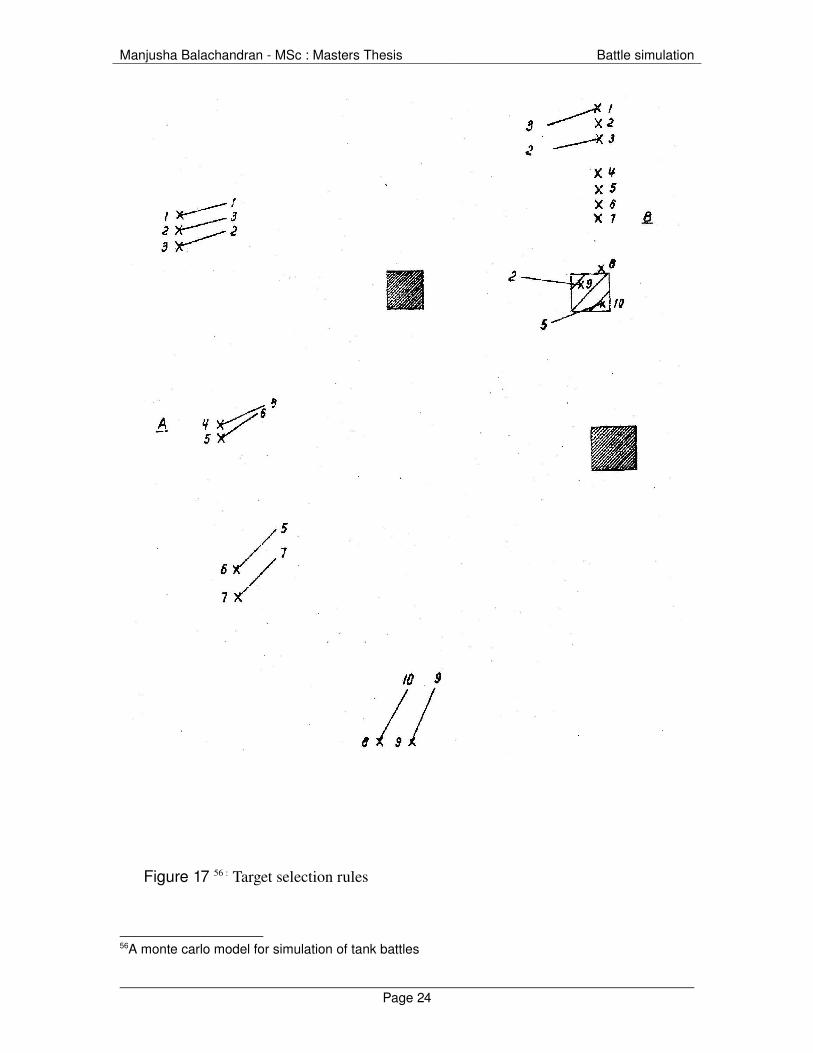
Figure 17 56 : Target selection rules
56A monte carlo model for simulation of tank battles
Page 24

Manjusha Balachandran MSc : Masters Thesis Battle simulation
In order to choose between the units of a subclass if there are more than one unit a general tactical rule for the target selection is used. – fire at the enemy unit which has a position in the enemy configuration corresponding to your own.
3. Coordination of target
This is used to generate a coordinate target selection for all units on one side to be used for simulation of surprise attacks
Depending on the enemy units that have been discovered the unit that has discovered the smallest number of enemy units selects target first. The selected enemy is then treated as fired on. This continues till every other unit has selected a target. This method gives a complete control on double firing.
1. According to this method the hit probabilities and other data is determined as follow:
For each combination of parameters hit probability is computed form a function of firing distance by linear interpolation
The other parameters taken into consideration are
a. firing unit:■ type of weapon (gun/missile)■ accuracy in estimated distance (2 levels)
b. target unit■ size of target(3 levels)■ velocity(2 levels)
2. when a unit is hit the damage is determined from the table of probabilities for possible transitions of the state
the probability is calculated as a function of firing distance
The time interval between the 2 firings are computed as tv+tf+tc (4)
Where
Page 25
Manjusha Balachandran MSc : Masters Thesis Battle simulation
tv is the sampled value from a given distribution
tf the flight tme for the last shot fired
tc constant value
2.1. Application
This model has been proposed for its usage in the weaponssystems study
Page 26

Manjusha Balachandran MSc : Masters Thesis Battle simulation
3. Fuzzy logic
3.1. History
The history of fuzzy logic dates back to 1965 when it was first published in the US by Lotfi Zadeh57, professor of systems theory at the University of California, Berkeley. From then on fuzzy logic has rapidly become one of the most successful technologies for developing sophisticated systems.
Fuzzy logic supports the generation of fast prototype and incremental optimization and delivers a more simple and transparent means of system design apart from being simple and easy to understand. This has enabled its usage in a variety of applications including the decision support data analysis applications, intelligence control and data processing applications, industrial automation and process control systems
A lot of research is being conducted in combining neural network and fuzzy logic, which is considered to be the technology of the future.
3.2. Introduction
Fuzzy logic can be defined as a problemsolving control system methodology that lends itself to implementation in systems ranging from simple, small, embedded microcontrollers to large, networked, multichannel PC or workstationbased data acquisition and control systems. It can be implemented in hardware, software, or a combination of both. 58
It is a simple, rulebased approach to a solving control problem rather than attempting to model a system mathematically. It requires numerical parameters in order to operate.
3.3. Features
FL offers several unique features such as
3.3.1. It is robust since it does not require precise, noisefree inputs. The output is smooth function despite a wide range of input variations.
57http://www.seattlerobotics.org/encoder/mar98/fuz/fl_part1.html#WHAT%20IS%20FUZZY%20LOGIC?58AI for Game Developers, Pg 190
Page 27
Manjusha Balachandran MSc : Masters Thesis Battle simulation
3.3.2. Fuzzy logic consists of userdefined rules which can be tweaked easily to improve or drastically alter system performance. The new rules can be easily incooperated into the system. Any reasonable number of inputs can be processed (18 or more) and numerous outputs (14 or more) generated,
3. The overall system cost and complexity low.
3.4. Implementation
The first step in implementing fuzzy logic is to decide exactly what is to be controlled and how59. The minimum number of possible input product combinations and corresponding output response conclusions using these terms have to be defined.
Linguistic variables are used to represent a fuzzy logic system's operating parameters. The rule matrix is a simple graphical tool for mapping the fuzzy logic control system rules. It accommodates two input variables and expresses their logical product (AND) as one output response variable.
3.4.1 Membership functions
The membership function is a graphical representation of the magnitude of participation of each input.
The rules use the input membership values as weighting factors to determine their influence or degree of membership60 on the fuzzy output sets. Once the functions are inferred, scaled, and combined, they are defuzzified into a crisp output which drives the system.
3.4.2. Putting it all together
The rulebase is evaluated according to the inputs. The antecedent blocks test the inputs and produce conclusions. The consequent blocks of some rules are satisfied while others are not. The conclusions are combined to form logical sums. These conclusions feed into the inference process where each response output member function's firing strength (0 to 1) is determined. The inputs can also be combined logically using the AND operator to produce output response values for all expected inputs. 59 Linguistic rules describing the control system consist of two parts; an antecedent block (between the IF and THEN) and a consequent block (following THEN). Depending on the system, it may not be necessary to evaluate every possible input combination.60 The degree of membership (DOM) is determined by plugging the selected input parameter (error or errordot) into the horizontal axis and projecting vertically to the upper boundary of the membership function(s).
Page 28

Manjusha Balachandran MSc : Masters Thesis Battle simulation
3.5. Fuzzy logic in massive
The general idea of fuzzy logic in massive is to represent continuously valued inputs and then combine them in rules to control outputs. The possible output values are also represented with fuzzy values.
It is implemented by creating a fuzzy logic network in the agents brain.
To create a fuzzy logic network various nodes in massive brain are used like input,fuzz, AND or OR, defuzz and output nodes.
Fuzzy values are defined by a membership function which is basically a simple curve. By applying the membership function to the input values, a degree of truth between 0 and 1 is generated. There are four standard membership function types in Massive
Figure 18 61: The membership function curves
Rules combine fuzzy values together to assert a fuzzy output value. There are several types of rules; AND62, OR63, NAND64 and NOR65.
Defuzzification is the process of turning fuzzy output values into 'crisp' output values.
The different defuzzification methods are:
Averaging function to produce a compromise value as the output
Crisp decision between the fuzzy values.
61http://nccastaff.bournemouth.ac.uk/jmacey/Massive/Fundamentals/html/step/02_02_11.html62 true when of the inputs are true63 true when at least any one of the inputs is true64 true when all of the inputs are not true.65 True when one of the inputs are not true
Page 29

Manjusha Balachandran MSc : Masters Thesis Battle simulation
3.6. Advantages Of Fuzzy Logic In Animation
In Massive, values in the environment changes over time and the trueness of certain fuzzy logic statements are constantly changing to reflect that.
Because the degree to which any rule is true affects the degree to which the fuzzy output is asserted, and this degree can change smoothly over time, changes in animation may be controlled smoothly.
For example consider a battle scene where the enemy soldier is approaching the agent. The agent could have different behaviors depending on the distance of the enemy soldier approaching the agent. When the enemy is far the agent could use the escaping tactics or even shoot at the enemy but when the enemy is near the agent must shoot at the enemy. Hence the behavior of the agent changes at every step creating a smooth animation.
Page 30

Manjusha Balachandran MSc : Masters Thesis Battle simulation
4. Massive software
Massive is the premier 3D animation system for the creation of behavioural simulation. It is used for generating crowdrelated visual effects for film and television.66
It is used to create intelligent characters that reacts to what is going around them. The reactions of the character determine what they do and how they do it. These are called as actions. These intelligent characters are called as agents.
Massive is a system for designing and simulating the behavior of the agents. Each agent can be designed with an individuality that distinguishes them within a crowd of agents.
4.1. Massive interface
Massive user interface consists of view window67, node window68, scene page69, Body page70, Brain Page 71, Motion Page72
4.2. Features of massive used in battle simulation
Massive has a lot of features, most of which have been used in this project and only those features have been documented in this report.
4.2.1. Channels
Channels are used to pass information between an agent's brain and it's body. Channels can be input or output nodes or both.
Refer to Appendix A for the list of channels.66 http://www.massivesoftware.com/whatismassive/] 67 displays the segments and geometry of the objects, and the terrain and the animation of the agents68 consists of the node work area, the node edit area, and the new node bar.69 used to edit the lights, cameras, groups, and terrain rendering options in the scene. lights and cameras can be imported and exported from Maya.70 The body page is used to edit the physical characteristics of an agent such as its segments, springs, geometry, cloth, materials, options and variation.71 is used for editing an agent's brain. It consists of nodes like input & output, timer & noise, fuzz & defuzz, and & or 72 The Motion Page is used to design the motions of an agent in the form of one or more motion trees
Page 31

Manjusha Balachandran MSc : Masters Thesis Battle simulation
4.2.2. Dynamics
Massive is capable of simulating realworld physics. Massive uses Rigid body dynamics to simulate the interaction of solid masses of virtually any shape or size involved in the simulation do not deform.
Dynamics can be used to enable terrain73, agent74, self collisions75, rotation constraints and springs76.
Refer to appendix A for dynamics related channels
4.2.3. Expressions
Expressions can be used in input nodes to modify or combine variables and channel values. Expressions can also be used to determine agent variable values.
4.2.4. Flowfiled
The flow field is directional information embedded into the alpha channel of the terrain map, which is useful for guiding agents around the terrain. It is made by placing flow splines onto the terrain and then clicking on the apply button to encode the flow field into the terrain map.
The flow field represents angles about the world Y axis from 0 to 360 degrees. When this data is referenced in an agent's input node. It is given relative to the agent's heading. The flow field can also be used to orient agents during placement by switching on the orient to flow flag for a generator.
4.2.5. Painting
The paint tool is used for painting the RGB channels of the terrain map. The terrain map can be used for placement of agents and as input data for agents.
73 collisions between any segment and the terrain model. 74 Collisions that occur between two segments from different agents.75 Collisions that occur between segments of the same agent but do not occur between a segment and it's parent.76 Are connected between segments of an agent
Page 32

Manjusha Balachandran MSc : Masters Thesis Battle simulation
4.2.6. Agent painting
Agents can also paint on the terrain beneath them as they move. In order for agent painting to work, the scene must contain a terrain and a terrain map.
Refer to appendix A for paint related channels
4.2.7. Placement
The most efficient way of creating multiple agents from one CDL is to create "instances" of the original agent. Instanced agents can differ from the original agent by the use of agent variables. A place editor is used for placing agents in the scene
Each instance shares data from the original agent to conserve memory and processor resources. An original agent will get default values for any agent variables. Instances are assigned their own values for the agent variables which can be used to vary segments, geometry, cloth, shader, textures and behavior.
4.2.8. Groups
An original agent and it's instances, along with some additional data, constitute a group.
A group contains of group name, CDL filename77, variables78 , locators79, a number of instanced agents
4.2.9. Spawning
Agents can also spawn from other agents using the spawn channel. For spawning to work, there need to be two existing agents, the spawner and the spawnee.
77 The CDL filename refers to the original agent's file. Group and agent in the scene page are associated by this field.78 Group variables can be used to override the agent variables. In this way the same original agent can be used with different variables in different places in the scene.79 Locators are used to specify the placement of instanced agents in the scene
Page 33

Manjusha Balachandran MSc : Masters Thesis Battle simulation
4.2.10. Rendering
Agent geometry and terrain geometry can be rendered using either hardware rendering80
or software rendering. 81
4.2.11. General Render FlowHardware rendering and software rendering differ in several key areas but follow a similar workflow. The general steps required are:
• Create render passes82.• Assign shaders to agents, terrain, and optionally lights for each render pass.• Create renders for the scene.• Write out files with the Sim dialog (these are the final images if rendering with
Velocity).• Render using resulting RIBs if using software rendering.
4.2.12. Sound
Sound allows an agent to perceive other agents, identify them, know where they are in relation to itself, and identify their current emotional state or action, in addition to communicating all this information about itself.
Sound can be used to keep agents from bumping into each other, or to cause some agents to follow others. Sound can be used to keep a group in formation by having an agent perceive the positions of its nearest neighbors and avoid getting too close, or too far ahead or behind. An agent can emit different frequencies to indicate to other agents its identity and status
Sound related channels
Refer to Appendix A for sound related channels
80 RenderMan renderers are used. The three RenderMan renderers Massive explicitly supports are Air, 3Delight, and Pixar's PRman renderer.81 Velocity renderer is used82 is a pass where you can assign specific shaders to agent geometry, terrain, and lights for that pass.
Page 34

Manjusha Balachandran MSc : Masters Thesis Battle simulation
4.2.13. Vision
Vision works in much the same way as sound, but there are differences between them. Vision requires much more processing than sound. It slows down the animation.
The second major difference is that vision is more precise than sound and enables the agent to make more precise decisions than with sound. Hence sound is used with environmental input that won't require highly specific reactions. Vision is used when environmental input that does require highly specific reactions.
Vision can distinguish between different segments of an agent and can also see terrain
Refer to Appendix A for Vision related channels
Page 35

Manjusha Balachandran MSc : Masters Thesis Battle simulation
5. Project Implementation
5.1. Aim of the project
The project aims at creating a realistic tank battle simulation. This simulation depicts the static warfare tactics of tank battles.
5.2. Scenario
The battle simulation consists of a war between two teams called the ‘red tanks’ and the ‘green tank’ in a dessert scenario. The simulation depicts a real time scenario which is inspired from the Bollywood movie ‘Border’ 83. The battle ends when one of the teams destroys maximum number of its enemy targets and surrounds the other not destroyed enemy targets.
The infantry simulation is a part of the tank battle simulation where the infantry uses the tank as a cover to attack the enemy in the whole war process.
The battle scene consists of a rigid terrain with buildings on one side. These buildings are guarded by the red tanks. The green tanks are placed on the other side of the terrain
The aim of the battle is that the red tanks must try to protect themselves and the buildings from being destroyed by the green tanks. The scenario is based on the green tanks being attackers and the red tanks being the defenders trying to protect the buildings. The green tanks at the same time must protect themselves from the being hit as well as protect the infantry that moves along with it
5.3 The setup file
The MAS file/massive scene consists of the following:
5.3.1. Agents
1. greentanks2. redtanks3. greeninfantry
83 http://www.imdb.com/title/tt0118751/. This movie is based on the India Pakistan fight in the year 1972..
Page 36

Manjusha Balachandran MSc : Masters Thesis Battle simulation
4. redinfantry5. redbuildings6. yellowbullets7. bluebullets8. antitankmines9. plantagents
5.3.2. Terrain
An uneven terrain with texture maps, flowfields and ground colour
5.3.3. Camera
A Massive scene has 4 cameras by default, each represented by a camera node. Animated camera nodes are created in order to create moving cameras.
The different animated camera options are:
off camera has no constraints
look at camera does not translate but rotates in place to keep target agent in center of view agent camera is constrained to agent axis of selected agent
segment camera is constrained to selected segment
pov camera is constrained to the agent's visionenabled segment,
if vision is on follow XZ camera follows agent in the XZ plane follow 3D camera follows agent in X, Y, and Z
5.3.4. Placement of the agents
The agents are placed in different formations to suit the desert scenario and the battle sequence
Page 37

Manjusha Balachandran MSc : Masters Thesis Battle simulation
5.4 Agents
The agents consists of a brain. They react to the surroundings depending on the fuzzy logic being programmed in the brain. The fuzzy logic decides how the agent reacts to the surroundings and what would be agents further course of action
5.4.1. Tank agent
The tank agent has the following features
1. Colour recognition
Recognize the enemy agent based on its color.
The behaviors based on color recognition are as follows:
In case of the same color
It must avoid each other and the other colour agents
It must not shoot the tanks and the agents of the same color
It must provide cover to the infantry of the same colour
It speeds when with other agents of the same colour
In case of different color
It must avoid the enemy agents
It should shoot when an enemy agent comes into the arena
It must choose the enemy target that is most dangerous
When an enemy agent is visible shoot until it is killed
When an enemy agent is killed, the tank must not shoot any more at that agent and choose a different enemy target
It must shoot in the direction of the target enemy agents
It slows down when encounter with enemy agents
Page 38

Manjusha Balachandran MSc : Masters Thesis Battle simulation
2. Terrain recognition
The tanks follow the steeps and slopes of the Terrain
3. Flowfield and ground colour recognition
The tanks can transition between different behaviour like reacting to the ground colour and the flowfields wherever necessary depending on the priorities of behaviour assigned to them
4. Vision
The tanks have a large vision to comprehend the advancement of the enemy agents from a distance
The green tanks can shoot from a distance as well as shoot the enemy when it is close to each other
5. Other features
The tanks try to prevent themselves from getting hit by trying to avoid themselves from the bullet by moving left and right depending on the position of the bullet
When the tank is shot at it changes its colour to black indicating that the tank is dead
A dead tank can no longer shoot at its enemy or move from its position
The tanks can shoot an enemy target while in motion or at a stationary position
A boundary has been defined for the agent to prevent the agents from going beyond the terrain.
Page 39

Manjusha Balachandran MSc : Masters Thesis Battle simulation
5.4.2. Bullet agents
The bullet agents have the following features:
The bullet agents are spawned out from the tank and the infantry agents
Different agents use bullets of different colors.
On a bullet colliding with an agent, should destroy the agents
5.4.3. Buildings
The buildings have the following features
They change in color when fired at them to show that the building is destroyed
5.4.4. Infantry agent
The infantry has the following features
1. Vision and color recognition
Recognize the enemy agent based on its colour.
The behaviours based on colour recognition are as follows:
In case of the same colour
It must avoid each other and the other agents
It must follow the tank agents of the same colour
It must not shoot the agents of the same colour
In case of different colour
It must avoid the enemy agents
It should shoot when an enemy agent comes into the arena
It must choose the enemy target that is most dangerous
Page 40
Manjusha Balachandran MSc : Masters Thesis Battle simulation
it must shoot at the enemy till it is killed.
When an enemy agent is killed, the infantry must not shoot any more at that agent and choose a different enemy target
Recognize the enemy agent based on its colour.
2.Terrain recognition
The infantry follows the steeps and slopes of the Terrain
3.Flowfield and ground colour recognition
The infantry can transition between different behaviour like reacting to the ground colour and the flowfields wherever necessary depending on the priorities of behaviour assigned to them
4. Vision
The infantry have a large vision to comprehend the advancement of the enemy agents from a distance
They can shoot from a distance as well as shoot the enemy when it is close to each other.
When the tank agent that is providing cover to the infantry is dead then the infantry seeks cover from the nearby tank agent of the same colour
5. Other features
The infantry tries to prevent themselves from getting hit by trying to avoid themselves from the bullet by moving left and right depending on the position of the bullet
When the infantry is shot change its colour to black and falls down indicating that the it is dead
Page 41
Manjusha Balachandran MSc : Masters Thesis Battle simulation
A dead infantry can no longer shoot at its enemy or move from its position
The infantry can shoot an enemy target while in motion or at a stationary position
A boundary has been defined for the agent to restrict the infantry movement within the boundary
5.4.5.. Antitank mines
When an enemy agent moves on these mines they change their colour to black indicating that they are dead.
5.4.6. Plant agents
They are obstacles on the path of the agents
5.5. The Fuzzy Pseudocode
5.5.1. Terrain avoidance
One challenge of the interaction with the environment is moving the agent over terrain in such a way that it adapts to the height and angle of the ground.
5.5.1.1. Logic:
■ If the terrain beneath the agent is high the agent should move upwards■ If the terrain beneath the agent is low the agent should move downwards■ If the terrain slopes upward the agent should tilt up■ If the terrain slopes downward the agent should tilt down■ If the terrain slopes to the right then the agent should tilt to the right■ If the terrain slopes to the left then the agent should tilt to the left
5.5.1.2. Fuzzy network:
Page 42

Manjusha Balachandran MSc : Masters Thesis Battle simulation
Figure 19 : Terrain adaptance
5.5.1.3. Implementation
1.To adapt to the height of the terrain
1a.Input:
Page 43
Manjusha Balachandran MSc : Masters Thesis Battle simulation
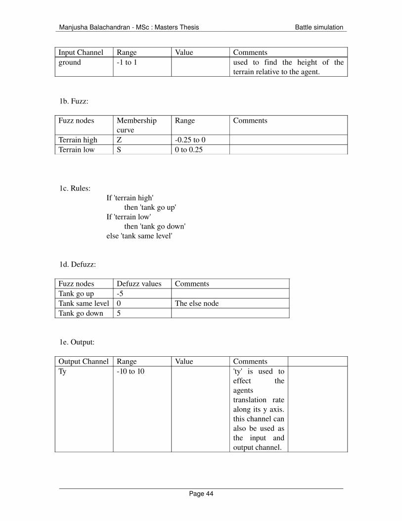
Input Channel Range Value Commentsground 1 to 1 used to find the height of the
terrain relative to the agent.
1b. Fuzz:
Fuzz nodes Membership curve
Range Comments
Terrain high Z 0.25 to 0Terrain low S 0 to 0.25
1c. Rules:If 'terrain high'
then 'tank go up'If 'terrain low'
then 'tank go down'else 'tank same level'
1d. Defuzz:
Fuzz nodes Defuzz values CommentsTank go up 5Tank same level 0 The else nodeTank go down 5
1e. Output:
Output Channel Range Value CommentsTy 10 to 10 'ty' is used to
effect the agents translation rate along its y axis. this channel can also be used as the input and output channel.
Page 44

Manjusha Balachandran MSc : Masters Thesis Battle simulation
2. To adapt to the slope of the terrain up and down
2a. Input:
Input Channel Range Value CommentsGround.dz 1 to 1 to find the
slope of terrain along agent z axes.
2b. Fuzz:
Fuzz nodes Membership curve
Range Comments
Terrain slope down
Z 0,5 to 0
Terrain slope up
S 0 to 0.5
2c. Rules:
If 'terrain slope down' then 'tank tilt forward'
If 'terrain slope up' then 'tank tilt backward'
else 'tank no tilt'
2d. Defuzz:
Fuzz nodes Defuzz values CommentsTank tilt forward
90
Tank no tilt 0 The else nodeTank tilt backwards
90
2e. Output:
Page 45

Manjusha Balachandran MSc : Masters Thesis Battle simulation
Output Channel Range Value CommentsRx 90 to 90 'rx' is used to
effect the agents rotation rate along its x axis. this channel can also be used as the input and output channel.
3. To adapt to the slope of the terrain left and right
3a. Input:
The input channel 'ground.dx' is used to find the slope of terrain along agent x axes.It is assigned a range between 1 to 1.
3b. Fuzz:
Fuzz nodes Membership curve
Range Comments
Terrain slope left
Z 0,5 to 0
Terrain slope right
S 0 to 0.5
3c. Rules:
If 'terrain slope left' then 'tank tilt left'
If 'terrain slope right' then 'tank tilt right'
else 'tank no tilt'
3d. Defuzz:
Fuzz nodes Defuzz values CommentsTank tilt left 90Tank no tilt 0 The else nodeTank tilt right 90
Page 46

Manjusha Balachandran MSc : Masters Thesis Battle simulation
3e. Output:
Output Channel Range Value CommentsRz 90 to 90 'rz' is used to effect the agents
rotation rate along its z axis. this channel can also be used as the input and output channel.
5.5.2.Vision
Vision is used by the agents to avoid collision with other agents and obstacles. Vision can be specified to a single segment of the body or the entire body. While simulating a tank battle simulation the vision is specified for a single segment. Here the hull segment is used to detect the presence of the other nearby agents in the scene. This includes the agent avoidance, the tank movement and the turret movemnet
5.5.2.1. Logic:
Vision is used to identify the tank by its colour
In case of same colour agents If the agent is to the left and near of the agent under consideration turn right If the agent is to the right and near of the agent under consideration turn left If the agent is to the centre and near of the agent under consideration slow the
agent and carry on the path In case of no obstacle on the path of the agent it carries on straight
In case of different colour agents■ If the agent is to the left and near of the agent under consideration turn right■ If the agent is to the right and near of the agent under consideration turn left■ If the agent is to the centre and near of the agent under consideration slow the
agent and carry on the path■ In case of no obstacle on the path of the agent it carries on straight
5.5.2.2 Fuzzy Network
Page 47

Manjusha Balachandran MSc : Masters Thesis Battle simulation
Figure 20 : Vision
5.5.2.3. Fuzzy logic:
1. Input:
Input Channel Range Value Commentsvision.h 0, 1 To identify the color of enemy
agentvision.x 1, 1 horizontal scan position offset to
align with agent space +ve z axisvision.z 0,1 distance
2. Fuzz:
Fuzz nodes Membership curve
Range Comments
Red Pi 0.1, 0.12, 0.15, 0.17
The colour of the nearby agent to decide if the agent is an enemy or not
Green Pi 0.28, 0.30, 0.35, 0.37
The colour of the nearby agent to decide if the agent is an enemy or not
Page 48

Manjusha Balachandran MSc : Masters Thesis Battle simulation
Right Pi 0.05, 0.27, 0.28, 1
The direction of the agent
Centre Lambda 0.18, 0 , 0.22 The direction of the agentLeft Pi 1, 0.29, 0.27,
0.02The direction of the agent
Near S 0.75, 0.85 The nearness of the agent
3. Rules for green tanks
If 'right and near and red and not dead and not paint and not flowfiled'Then turn left
If ‘left and near and red an not dead and not paint and not flowfiled'Then turn right
If ‘red and right and nearThen avoid
If red and left and near Then avoid
If red and centre and nearThen avoid and slow
Else normal speed
4. Rules for red tanks
If 'right and near and green and not dead and not paint and not flowfiled'Then turn left
If ‘left and near and green an not dead and not paint and not flowfiled'Then turn right
If ‘green and right and nearThen avoid
If green and left and near Then avoid
If green and centre and nearThen avoid and slow
Else normal speed
5. Defuzz:
Segment Defuzz nodes Defuzz values CommentsTurret Straight 0 The else node
Page 49

Manjusha Balachandran MSc : Masters Thesis Battle simulation
Turn left 300Turn right 300
Wheels Wheels left 50Wheels right 50Wheels straight 0 The else node
Tank left 120Tank right 120Tank straight 0 The else node
Slow 0.4Normal 1
6. Output
Segment Output Channel Range Value CommentsTurret Ry 300 to 300 'ry' is used to
effect the agents rotation rate along its y axis. this channel can also be used as the input and output channel.
Avg
Wheels Front_right_w:ry 50 to 50 BlendFront_left_w:ry 50 to 50 Blend
Ry 120 to 120 'ry' is used to effect the agents rotation rate along its y axis. this channel can also be used as the input and output channel.
avg
Tz 0 to 1 ‘tz’ is used to effect the agents translation rate along its z axis. this
Page 50
Manjusha Balachandran MSc : Masters Thesis Battle simulation
channel can be used both as the input and output channel
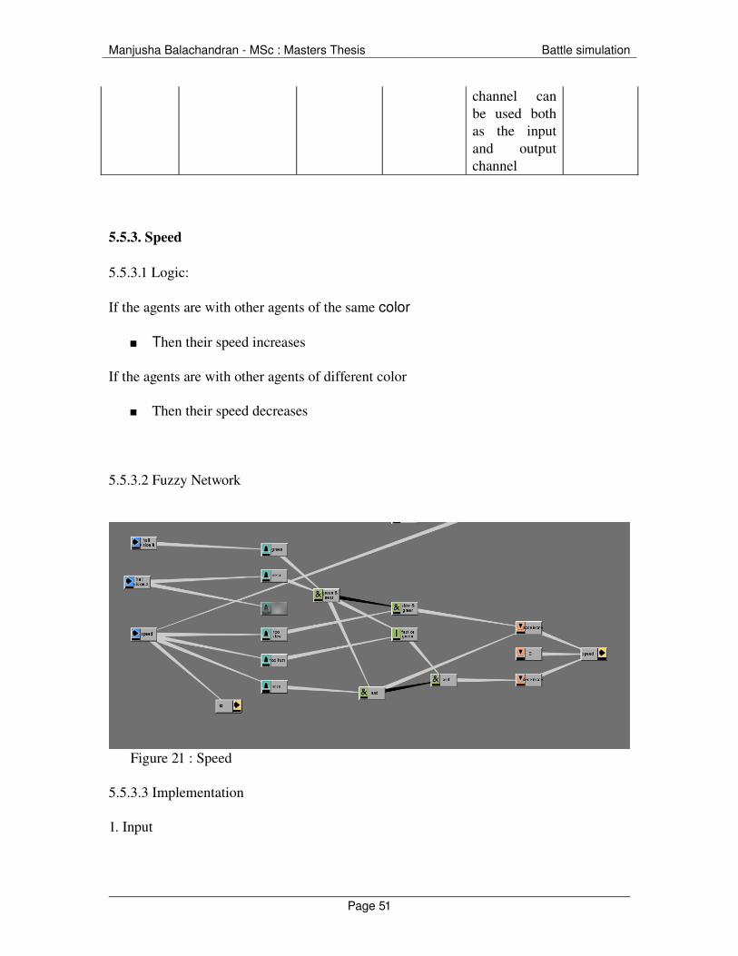
5.5.3. Speed
5.5.3.1 Logic:
If the agents are with other agents of the same color
Then their speed increases
If the agents are with other agents of different color
Then their speed decreases
5.5.3.2 Fuzzy Network
Figure 21 : Speed
5.5.3.3 Implementation
1. Input
Page 51
Manjusha Balachandran MSc : Masters Thesis Battle simulation
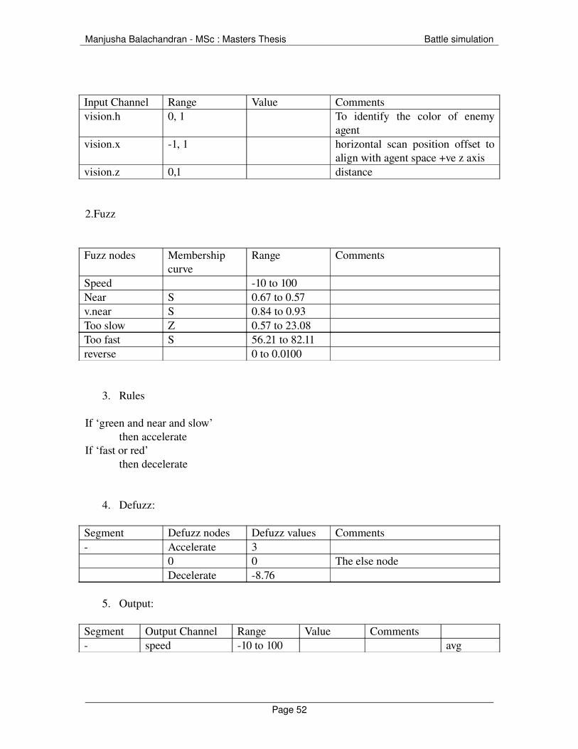
Input Channel Range Value Commentsvision.h 0, 1 To identify the color of enemy
agentvision.x 1, 1 horizontal scan position offset to
align with agent space +ve z axisvision.z 0,1 distance
2.Fuzz
Fuzz nodes Membership curve
Range Comments
Speed 10 to 100Near S 0.67 to 0.57v.near S 0.84 to 0.93Too slow Z 0.57 to 23.08Too fast S 56.21 to 82.11reverse 0 to 0.0100
3. Rules
If ‘green and near and slow’ then accelerate
If ‘fast or red’ then decelerate
4. Defuzz:
Segment Defuzz nodes Defuzz values Comments Accelerate 3
0 0 The else nodeDecelerate 8.76
5. Output:
Segment Output Channel Range Value Comments speed 10 to 100 avg
Page 52

Manjusha Balachandran MSc : Masters Thesis Battle simulation
5.5.4. Flow field
Flow fields are a convenient way to direct the agents along a set path. Agents are guided by the influence of vector definitions that populate a given space. It is also called a vector field, and is a collection of vectors associated to every point in a given space.
5.5.4.1. Logic:
■ If the orientation of the flowfield is to the left then turn left■ If the orientation of the flowfield is to the right then turn right■ If not continue the path ie go straight
5.5.4.2 Fuzzy Network:
Figure 22 : Flow field
5.5.4.3. Implementation:
1.Input:
Input Channel Range Value CommentsGround.flow 90 to 90
2. Fuzz:
Fuzz nodes Membership curve
Range Comments
Page 53

Manjusha Balachandran MSc : Masters Thesis Battle simulation
Left S check 38.89, 0.5Straight Lambda 37.41, 0.5,
31.62Right Z 0.25, 31.6835
3. Rules:
Here a priority node is assigned to the flow field.
If 'flow and left' then 'wheel_left', 'left'
If 'flow and right'then 'wheel_right', 'right'
If 'flow and straight'then ' straight', 'go on'
4. Defuzz:
Segment Defuzz nodes Defuzz values Commentswheel wheel_left 50 only the wheels rotatewheel straight 0wheel wheel_right 50 turn_right 90 whole body of tank rotates turn_left 90 go_on 0
5. Output:
Segment Output Channel Range Value Commentswheel front_right_ry 50, 50wheel front_left_ry 50, 50 ry 90, 90
5.5.5. Ground colour
Colour maps are two dimensional images assigned or 'mapped' to a three dimensional object. The colour maps in Massive use four colour channels; red, green, blue and alpha
Page 54

Manjusha Balachandran MSc : Masters Thesis Battle simulation
(or transparency). Colour maps can be imported, painted in Massive, or painted by the agents themselves during the simulation. Agents can read and respond to colour as they pass over the surface of the terrain. This helps agents to react differently to marked areas as well as follow paths.
5.5.5.1 Logic:
■ If the colour gradient path is to the right and front of the agent turn left ■ If the colour gradient path is to the right and back of the agent turn right ■ If the colour gradient path is to the left and front of the agent turn right ■ If the colour gradient path is to the left and back of the agent turn right
5.5.5.2 Fuzzy Network:
Figure 23 : Colour
5.5.5.3 Implementation:
1. Input:
Input Channel Range Value CommentsGround.b 0 to 1
2. Fuzz:Fuzz nodes Membership
curveRange Comments
Blue S 0,0.5
3. Rules If Blue and not dead then slow
Page 55

Manjusha Balachandran MSc : Masters Thesis Battle simulation
Else normal speed
4. Defuzz:Segment Defuzz nodes Defuzz values Comments Slow 0.03
Normal speed 1 The else node
5. Output:Segment Output Channel Range Value Comments tz 0 to 1 avg
5.5.6. Boundary
To create a boundary for the agents movements so that the agent will turn on reaching the end of the screen
5.5.6.1. Logic:i. If the terrain map colour is green turn left
ii. If not continue on its path, ie go straight
ground.g = the amount of green beneath the agent
5.5.6.2 Fuzzy Network:
Figure 24 : Boundary
5.5.6.3 Implementation:
1. Input:
Input Channel Range Value Comments
Page 56

Manjusha Balachandran MSc : Masters Thesis Battle simulation
Ground.g 0 to 1
2. Fuzz:
Fuzz nodes Membership curve
Range Comments
green S 0,1
3. Rules
If green then turn left
elsego straight
4. Defuzz:
Segment Defuzz nodes Defuzz values Comments straight 0
left 200
5. Output:
Segment Output Channel Range Value Comments ry 0, 200
5.5.7. The shooting controls
The infantry uses shooting controls to attack the enemy.
5.5.7.1. Logic:
If the tank near by is the enemy tank then shoot. If the enemy tank is dead then do not shoot in its direction. Choose the next closest enemy tank as the target.
5.5.7.2 Fuzzy Network:
Page 57

Manjusha Balachandran MSc : Masters Thesis Battle simulation
Figure 25 : Shooting rules
5.5.7.3 Implementation:
1. Input:
Input Channel Range Value Commentsvision.h 0, 1 To identify the color of enemy
agentvision.x 1, 1 horizontal scan position offset to
align with agent space +ve z axisvision.z 0,1 distance
2. Fuzz:
Fuzz nodes Membership curve
Range Comments
Red Pi 0.1, 0.12, 0.15, 0.17
The colour of the nearby agent to decide if the agent is an enemy or not
Green Pi 0.28, 0.30, 0.35, 0.37
The colour of the nearby agent to decide if the agent is an enemy or not
Right Pi 0.05, 0.27, 0.28, 1
The direction of the agent
Centre Lambda 0.18, 0 , 0.22 The direction of the agentLeft Pi 1, 0.29, 0.27,
0.02The direction of the agent
Page 58

Manjusha Balachandran MSc : Masters Thesis Battle simulation
Near S 0.75, 0.85 The nearness of the agent
3. Rules for green tanks
If red and right and near and not dead then shootIf red and left and near and not dead then shootIf red and centre and near and not dead then shootElse
No shooting
4. Rules for red tanks
If green and right and near and not dead then shootIf green and left and near and not dead then shootIf green and centre and near and not dead then shootElse
No shooting
5. Defuzz:
Segment Defuzz nodes Defuzz values Comments Shoot 100
Noshooting 0 The else node
6. Output:
Segment Output Channel Range Value Comments Bulletblue:spawn 0,100 Avg in case of green tanks Bulletyellow:spawn 0,100 avg in case of red tanks
5.5.8. The death rules
These are the rules followed by the agent when it is shot by an agent.
5.5.8.1. Logic:
If the agent bullet is at a distance less than 0.95 from the enemy then the agent is killed.
Page 59

Manjusha Balachandran MSc : Masters Thesis Battle simulation
5.5.8.2. Fuzzy Network:
Figure 26 : Death rules
5.5.8.3. Implementation:
1. Input
Input Channel Range Value CommentsSound.d 0.9 to 1vision.h 0 to 1Dead 0,1
2. Fuzz:Fuzz nodes Membership
curveRange Comments
yellow pi 0.2, 0.21, 0.23, 0.24
blue pi 0.5, 0.51, 0.53, 0.54
3. Rules for green tanks
If ‘sound.d >0.95’ and ‘bullet’ is yellow or ‘dead’ then change the colour to black
Page 60

Manjusha Balachandran MSc : Masters Thesis Battle simulation
4. Rules for red tanks
If ‘sound.d >0.95’ and ‘bullet’ is blue or ‘dead’ then change the colour to black
5. Output:
Segment Output Channel Range Value Comments Dead 0,1 Avg Clour 0,1 Avg
5.5.9 Reaction on Destroyed
5.5.9.1. Logic:
In case of the tank
Once the tank is hit the amplitude and the frequency of the sound emitted by it decreases. This is done so that the infantry following this tank can understand that the tank is dead
In case of the infantry
Once the infantry is shot it rotates in the rx axis to represent falling
5.5.9.2. Fuzzy Network:
Page 61
Manjusha Balachandran MSc : Masters Thesis Battle simulation
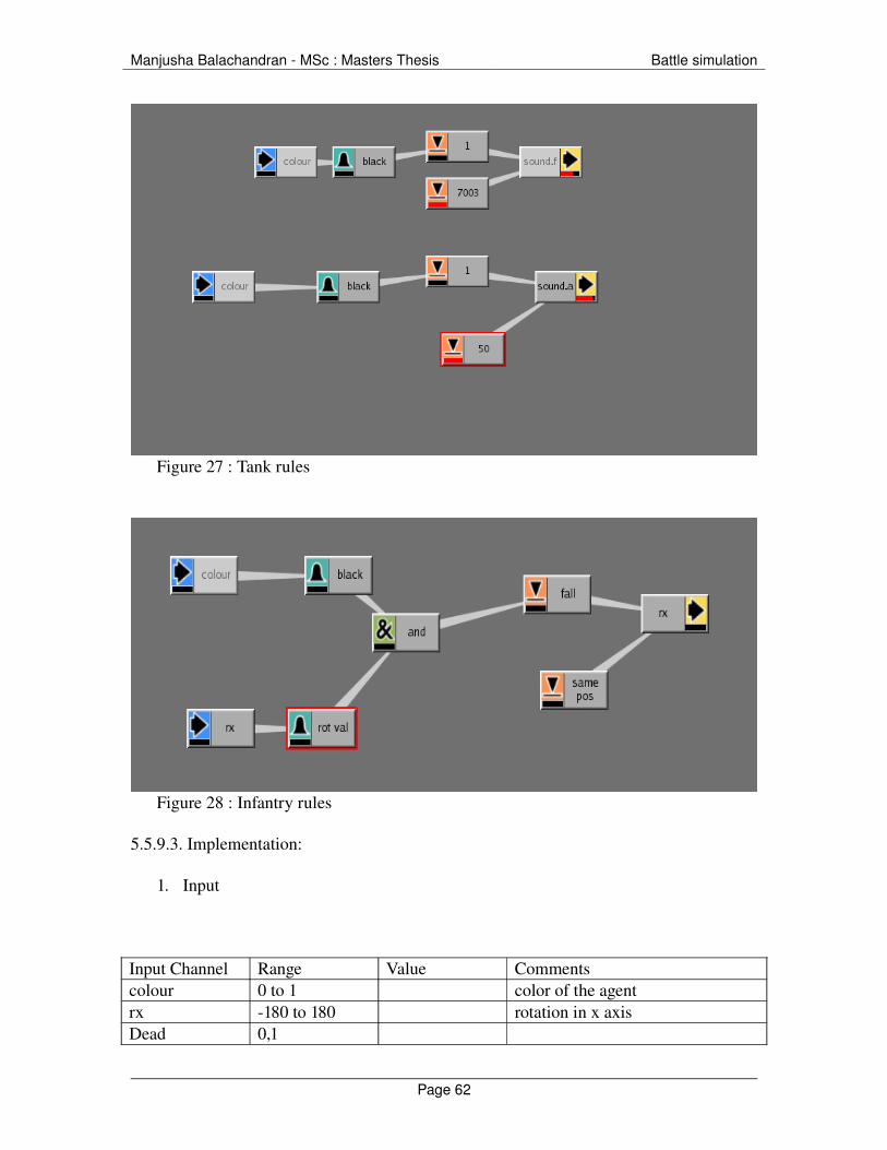
Figure 27 : Tank rules
Figure 28 : Infantry rules
5.5.9.3. Implementation:
1. Input
Input Channel Range Value Commentscolour 0 to 1 color of the agentrx 180 to 180 rotation in x axisDead 0,1
Page 62

Manjusha Balachandran MSc : Masters Thesis Battle simulation
2. Fuzz:
Fuzz nodes Membership curve
Range Comments
black S 0,1rotval S 32, 3
3. Rules for tanks
If ‘color’ black then 'sound.f' is 0then 'sound.a' is 0
4. Rules for infantry
If 'color' black then 'rx' is 180
5. Defuzz
Segment Defuzz nodes Defuzz values Comments 1 1 7003 7003 the else node 1 1 50 50 the else node fall 180 same position 0 the else node
5. Output:
Segment Output Channel Range Value Comments sound.f 1, 10000 Avg sound.a 1, 100 Avg
5.5.10. Flocking
Vision /Sound
Page 63

Manjusha Balachandran MSc : Masters Thesis Battle simulation
This includes the green agent avoidance, the infantry movement and the green infantry flocking by the green tanks
Sound can be used to keep agents from bumping into each other, or to cause some agents to follow others. This is very similar to using vision in agents
5.5.10.1. Logic:
If the agent is to the left and near of the agent under consideration turn right If the agent is to the right and near of the agent under consideration turn left If the agent is to the centre and near of the agent under consideration slow the
agent and carry on the path In case of no obstacle on the path of the agent it carries on straight If the agent is to the extreme left of the agent under consideration turn right If the agent is to the extreme right of the agent under consideration turn left
5.5.10.2. Fuzzy Network
Figure 29 : Flocking
5.5.10.3. Implementation
Page 64

Manjusha Balachandran MSc : Masters Thesis Battle simulation
1. Input
Input Channel Range Value Commentssound.d 0,1sound.x 180,180sound.froot:vision.hflow
2. Fuzz
Fuzz nodes Membership curve
Range Comments
near S 0.75, 0.86far Z 0.64, 0.83left Pi 170, 126, 80,
0centre Lambda 60, 0, 60right Pi 0, 81, 132, 170tank sound Pi 6738, 6838,
7193, 7325red Pi 0.10, 0.12, 0.15,
0.17green Pi 0.28, 0.30,
0.35, 0.37left Z 38, 0.5straight lambda 37, 0.5, 31right S 0.25, 31.68
3. Rules
If 'left and near and not flow and not dead' then turn right
If 'near and centre and not flow and not dead' then slow
If 'near and right and not flow and not dead' then turn left
If 'far, left and leader and not flow and not dead' then turn right
If 'far, right and leader and not flow and not dead' then turn left
Page 65

Manjusha Balachandran MSc : Masters Thesis Battle simulation
4. Defuzz
Segment Defuzz nodes Defuzz values Commentsright 90straight 0left 90slow 0normal 0.7
5. Output
Segment Output Channel Range Value Comments ry 90 to 90 tz 0 to 3
Page 66
Manjusha Balachandran MSc : Masters Thesis Battle simulation
6. To apply geometry/texture to the agents
A geometry , material node is used to assign geometry and textures to the agents
A renderman shader can be assigned to a material node, and even assign surface textures using variable names in order to allow the agent to dynamically choose texture maps.
6.1. Assigning renderman shaders
The shaders tab enables to assign shaders for each render pass to the material node.
The two types of renderman shaders that can be assigned are surface shader and displacement shaders.
The procedure followed while rendering using renderman are as follows
Create a render pass by using options>renderers
Assign a renderer to the renderpass and adjust the parameters as desired.
Select the material tab in the body page and select the shaders tab at the bottom of the window.
Select the appropriate render pass from the list
Then select a surface shader or a displacement shader. This opens up a RenderMan shader dialog with a variety of shader options to choose from. Adjsut the paramets of the shader as required and close the dialog box
This shader will now be used when the particular pass is rendered.
The same procedure can be followed to assign terrain shaders.
6.2. Rendering
Software rendering in Massive is not performed directly by Massive itself but by (1) a Renderman compatible renderer such as PRman, Air, or 3Delight, or (2) Mental Ray.
Page 67
Manjusha Balachandran MSc : Masters Thesis Battle simulation
The process requires RIB files (or .mi files for Mental Ray), which can be written out from Massive and contains instructions for the renderer. It also requires a program called massive.so (or run_program.exe for Air) which is called by the renderer during rendering and gives the renderer further information about the scene.
In a rendering pipeline, RIB files are written out with all the information about the scene, including geometry and shader data. Massive RIB files only contain a minimal amount of information and call upon the massive.so program to look at the agent files and get the rest of the information while the render is running.
6.2.1 Create a render
To create a renderer choose the option renders and create a new renderer.
Select the 'parameters' tab to set parameters for this new render.
Choose a render pass from the pulldown menu that reflects the software renderer Prman
This render will now render the agents and terrain using the shaders specified in that render pass..
6.2.2 To batch render
To batch render,the RIB and Sim files have to be written out.
Select Run: Sim from the main menu.
Set the start frame and the end frames.
Select sims under the output section and assign a desired path for the files
Select ribs under the output section. and assign a desired path for the files
Set the sims output format to amc.
Set the ribs file pattern to read 'Rib/men.#.rib'. (Or replace 'Rib/' with whatever file path is used.)
Choose the dynamic load option when using the PRman renderers.
Page 68

Manjusha Balachandran MSc : Masters Thesis Battle simulation
Now select the required rendered and hit the go button to run the sim and write out these files.
6.2.3. Render with script
These files are now written out and everything is ready for rendering. The rendering will be done from outside of Massive
Find the Rib and Sim directories and ensure the files have been written out.
A file 'render_script.sh' is created in the directory from which massive is launched.
This file is written out whenever you write out RIB files from Massive. It is a shell script that can be run from a Linux command line and contains a series of instructions to render each frame one by one.
Change the permissions on the script so you can run it by typing 'chmod 755 render_script.sh'.
Run the script by typing './render_script.sh'.
This renders each frames in a Tif format.
6.2.4. To create an Open Gl render
Select Run: Sim from the main menu.
Set the start frame and the end frames.
Select pics under the output section and assign a desired path for the files and hit the button go
Page 69
Manjusha Balachandran MSc : Masters Thesis Battle simulation
7. The final artwork
The scenes are rendered and imported into shake to create a better visual looking piece of work. The various changes created to the scene are as follows
The terrain and the sky are replaced to make the scene look more dramatic.
As the animation was imported to shake the terrain has lost its curves and looks flat.
As massive cannot imported animated obj file the movement of a tank in a real scenario looks a little artificial. In order to make the whole scene more believable, to hide the wheels that are not rotating, in a further version the tanks would be made more realistic, with dust on its wheels and shadows.
Page 70
Manjusha Balachandran MSc : Masters Thesis Battle simulation
8. The technical constraints during the entire project period
The massive version installed is very unstable and it crashes without any error messages.
When the system crashes it corrupts the files and also the different versions of the files
The system freezes on the usage of the collide command. While trying to implement a tank system reacting to dynamics on collision with the bullet the system froze without any error messages.
Sometimes when changes are made to the agent Massive does not register the changes immediately unless the system is restarted.
At times the agent the agent behaves not as expected in the view port even though the agent output behavior is right
This version of Massive cannot load many agents with complex geometry. the system freezes again. Sometimes even when it works the animation is too slow
While exporting Massive animation to Maya as particle disk cache format, Massive imports a pool of particles to which a geometry can be attached. In case of many agents Massive does not differentiate between the animation of different agents.
Page 71

Manjusha Balachandran MSc : Masters Thesis Battle simulation
9. The problems with the system.
Due to absence of Massive mocaop files, the system was restricted to the use of static obj files. The soldiers had to be implemented as a non animated object files. The simulation would have given them a more realistic look and feel.
As dynamics could not be implemented the tanks are shot on basis of approximation. The reaction of a tank after being bombed( i.e.tank blasting into pieces etc. could not be implemented)
Page 72
Manjusha Balachandran MSc : Masters Thesis Battle simulation
10. Conclusion
The aim of project was to develop a comprehensive, yet easy to implement, realistic battle simulation. The ease of use has certainly been achieved, as these agents can be used in different scenarios.
The system consists of a prototype that can be reused in any kind of a scenario. The agents use fuzzy rules to display intelligent behavior. This enables the agents to collect information of the terrain and the battlefield to make decisions. They have generic behaviors such as avoiding obstacles, avoiding enemies, following a leader, shooting the enemy, preventing themselves from being an enemy target, etc. Most of the decisions made by the agent in this system depends on the colour of the agent in its vision. The agent makes decisions at runtime depending on the scenario and the placement of the agents on the terrain.
The current implementation consists of multiple agents, the tanks and the infantry being the most important ones. The tanks and infantry follow some generic rules and some specific rules. As mentioned earlier, the decision making ability of the agents is based on the colour. The back bone of this simulation is recognising if an agent is an enemy or not from the colour of other agent. Based on this recognition factor, the infantry and the tanks act accordingly. The infantry always follows a tank for cover, and when the tank providing cover is dead, the infantry moves to the nearest tank of its own kind( in this case on basis of colour).
The buildings are destroyed when they are shot at by the tanks. There are anti tank mines placed over the terrain, which destroy agents of the enemy colour when the tanks go over them.
The simulation graphics look very simple. The disadvantage of massive is that it cannot import animated object files. Hence Massive animation has to be either exported to Maya or Houdini and animated object files can be attached to it. Even this process was complicated as the Maya particle disk cache files created were just a pool of particles. They could not be associated with separate agents.
The rules work very well and gives the flexibility to include more complicated rules if a scenario demands it. Complex rules can be created using dynamic simulations which could not be implemented in this case as the system could not handle the same due to Beta version limitations while performing dynamic calculations.
Page 73

Manjusha Balachandran MSc : Masters Thesis Battle simulation
Every step of this project was complex and had different challenges to offer. The infantry are 3D objects and simulation could have been made more realistic, if the infantry could be animated.
The experience to work in Massive was very interesting & a very good learning experience. To create intelligent agents displaying emergent behavior is always challenging.
Page 74
Manjusha Balachandran MSc : Masters Thesis Battle simulation
11. Future work
The tanks and the infantry consists of basic rules of tank and infantry tactics in a warfare.Hence the following can be done to make the simulation more realistic
Dynamics can be implemented in order to create more realistic simulations like the way a agent reacts with the force of being hit. The tanks can break down and the infantry fall down realistically on being shot.
To import predefined actions for each of the agents in Massive and to program to use those behaviors in order to create simulations would be an interesting task.
To create an user interface with the available options in Massive and to create a game out of the same would be another possible avenue.
To build agents that can understand the entire terrain map and the placements of the other agents at the point of simulation and behave accordingly.
To involve large number of agents in the simulation.
Page 75

Manjusha Balachandran MSc : Masters Thesis Battle simulation
12. Appendix A
Agent Channels
Channel description input / output
min max example
tx ty tz translation rate of agent
both inf inf ty
rx ry rz rotation rate of agent both inf inf rylx ly lz lean of agent in world
space (see lean)input 1 1 ly
collide indicates the occurance and depth of a collision with another agent
input 0 inf collide
collide.v velocity of collision input 0 inf collide.vcollide.x collide.y collide.z
location of collision in agent space
input inf inf collide.x
collide.vx collide.vy collide.vz
velocity vector of collision in agent coordinates
input int int collide.vx
collide.nx collide.ny collide.nz
normal vector of collision in agent coordinates
input 1 1 collide.nx
ground height of terrain relative to agent(see terrain)
input inf inf ground
ground.r ground.g ground.b ground.a
colour of terrain beneath agent
input 0 1 ground.r
ground.dx ground.dz
slope of terrain along agent x and z axes
input inf inf ground.dx
ground.r.dx ground.g.dx ground.b.dxground.r.dz ground.g.dz ground.b.dz
gradient of terrain R G and B withrespect to agent X and Z axes.
input inf inf ground.r.dx
balance.x balance.z
distance that agent is off balance in x and z
input inf inf balance.x
sound.f sound.a sound emmission / both 0 inf sound.f
Page 76

Manjusha Balachandran MSc : Masters Thesis Battle simulation
sound.f1f sound.f1asound.f2f sound.f2a
reception (see sound)
sound.d sound.x sound.z
see sound input sound.d
wind.x wind.y wind.z
velocity of wind (see wind)
both inf inf wind.x
wind.a wind.f amplitude and frequency of wind turbulence
output 0 inf wind.a
dynamics.active activates rigid body dynamics for the agent (see dynamics )
output 0 1 dynamics.active
vision.active switches off vision processing if set to zero (default value is one).
output 0 1 vision.active
active switches as agent off if set to zero
output 0 1 active
parent causes an agent to become parented to an agent with which it is colliding
output 0 1 parent
keyboard Ascii code for the key that was pressed. For realtime keyboard control of agents.
input 0 65535
keyboard
controller.joy1.xcontroller.joy1.ycontroller.joy2.xcontroller.joy2.ycontroller.joy3.xcontroller.joy3.ycontroller.slidercontroller.b1..controller.b8
Gamepad controller joysticks, d pad, trim slider and buttons. For realtime control of agents.
(see joystick/keyboard controls)
input 0 1 controller.joy3.x
servo.force magnitude of servo force to be used for all degrees of freedom for all segments (see
output 0 inf servo.force
Page 77

Manjusha Balachandran MSc : Masters Thesis Battle simulation
dynamics) paint.r, paint.g, paint.b, paint.a
level of red/green/blue/alpha channels that agent paints on the ground
output 0 1 paint.r
paint.size size of brush agent uses to paint on the ground
output 0 inf paint.size
colour colour of agent's skeleton
input/output 0 1 colour
Segment Channels
channel description input / output
min max
example
tx ty tz segment translation
both inf inf head:ty
rx ry rz segment rotation
both inf inf head:ry
x y z segment location in agent space
input inf inf head:y
lx ly lz lean of segment in world space (see lean )
input 1 1 head:ly
h height of segment above ground in world space
input inf inf r_hand:h
mass segment mass
output 0 inf head:mass
dynamics.active activates dynamics for the segment and it's descendants
output 0 1 head:dynamics.active
dynamics.detach specfies whether segment, if dynamic,
output 0 1 l_shoulder:dynamics.detach
Page 78
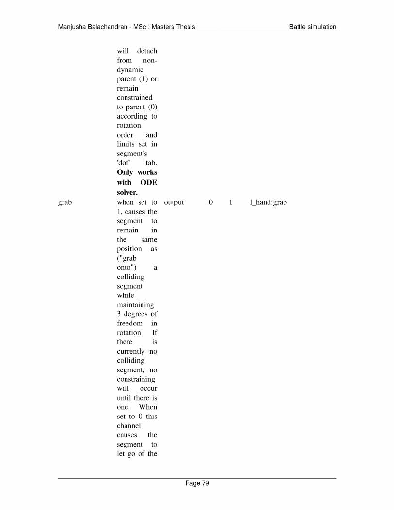
Manjusha Balachandran MSc : Masters Thesis Battle simulation
will detach from nondynamic parent (1) or remain constrained to parent (0) according to rotation order and limits set in segment's 'dof' tab. Only works with ODE solver.
grab when set to 1, causes the segment to remain in the same position as ("grab onto") a colliding segment while maintaining 3 degrees of freedom in rotation. If there is currently no colliding segment, no constraining will occur until there is one. When set to 0 this channel causes the segment to let go of the
output 0 1 l_hand:grab
Page 79

Manjusha Balachandran MSc : Masters Thesis Battle simulation
colliding segment. This channel can be switched on and off any number of times while the dynamics engine is still running. Only works with ODE solver.
force.xforce.yforce.z
External force applied to segment. Forces only have effect when dynamics is active
output inf inf r_shoulder:force.z
force.pxforce.pyforce.pz
Location in segment space at which force is applied.
output inf inf r_shoulder:force.px
force.rxforce.ryforce.rz
Torque applied to segment.
output inf inf head:force.ry
ground height of terrain under segment relative to agent (see terrain )
input inf inf r_foot:ground
ground.r ground.g ground.b ground.a
colour of terrain beneath segment
input 0 1 l_foot:ground.r
ground.r.dx ground.g.dx
gradient of terrain R G
input inf inf l_foot:ground.r.dx
Page 80
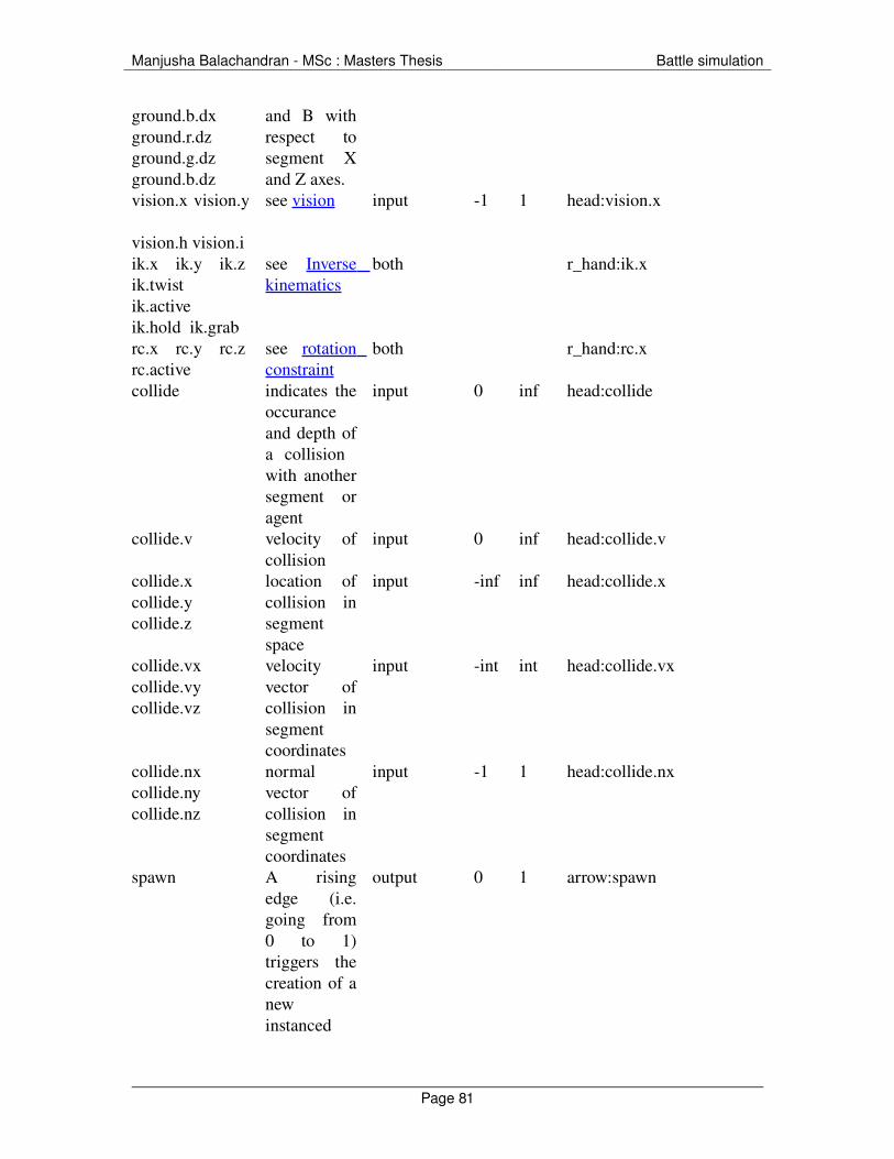
Manjusha Balachandran MSc : Masters Thesis Battle simulation
ground.b.dxground.r.dz ground.g.dz ground.b.dz
and B withrespect to segment X and Z axes.
vision.x vision.y
vision.h vision.i
see vision input 1 1 head:vision.x
ik.x ik.y ik.z ik.twistik.active ik.hold ik.grab
see Inverse kinematics
both r_hand:ik.x
rc.x rc.y rc.z rc.active
see rotation constraint
both r_hand:rc.x
collide indicates the occurance and depth of a collision with another segment or agent
input 0 inf head:collide
collide.v velocity of collision
input 0 inf head:collide.v
collide.x collide.y collide.z
location of collision in segment space
input inf inf head:collide.x
collide.vx collide.vy collide.vz
velocity vector of collision in segment coordinates
input int int head:collide.vx
collide.nx collide.ny collide.nz
normal vector of collision in segment coordinates
input 1 1 head:collide.nx
spawn A rising edge (i.e. going from 0 to 1) triggers the creation of a new instanced
output 0 1 arrow:spawn
Page 81

Manjusha Balachandran MSc : Masters Thesis Battle simulation
agent. The new agent will instanced from an original agent with the same name as the segment.
servo.force magnitude of servo force to be used for all degrees of freedom for the segment (see dynamics)
output 0 inf head:servo.force
servo.force.x servo.force.y servo.force.z
magnitude of servo force to be used for individual degrees of freedom for the segment (see dynamics)
output 0 inf head:servo.force.x
servo.rx servo.ry servo.rz
sets the target rotation values for the servos for the segment. Note that these values are overriden by actions (see dynamics)
output inf inf head:servo.rx
colour colour of segment
input/output 0 1 head:colour
Page 82

Manjusha Balachandran MSc : Masters Thesis Battle simulation
Action Channels
channel description input / output
min max
example
action A value of 1 triggers the action. A value of 2 triggers the action irrespective of latch state (see actions )
output 0 2 walk
action The activation level of the action
input 0 1 walk
action1>action2 Blends action2 over action1
output 0 1 walk>sidestepL
[channel]:scale Scales the action values applied to the channel.
output inf inf [head:ry]:scale
[channel]:offset Offsets the action values applied to the channel.
output inf inf [head:ry]:offset
[channel]:origin Sets the origin for scaling of the channel
output inf inf [r_toes:ik.y]:origin
action:rate Sets the playback rate. 0.5 causes the action to play at half speed. 1 causes it to play backwards.
both inf inf walk:rate
action:running A binary value indicating wether the the action is playing or not.
input 0 1 walk:running
action:phase The phase of the playback of the action
input 0 1 walk:phase
phase The phase of the most active playback on track 1
input 0 1 phase
phase2 ... phase8 The phase of the most active playback on tracks 2 to 8
input 0 1 phase5
action:phase_offset Sets the starting phase offset for the action.
output 0 1 walk:phase_offset
latch The state of the latch intput 0 1 latch
Page 83

Manjusha Balachandran MSc : Masters Thesis Battle simulation
for track 1
Page 84
Manjusha Balachandran MSc : Masters Thesis Battle simulation
13. Bibliography
1. Andersson, S. “A Monte Carlo Model for Simulation of Tank Battles.” 1966
2. “Attack phase”. Accessed on 1 Sep 2007<http://www.tqnyc.org/NYC073871/mobile_warfare_ex2.htm#1>
3. Creative Source. “The origin of civilization.” Accessed on 5 Sep 2007. <http://www2.hawaii.edu/~yakovee/theorigin.htm>
4. Dunnigan, J. “Designing Computer Games”. Posted in 1997. Accessed on 1 Sep 2007. <http://www.hyw.com/Books/WargamesHandbook/71spec.htm>
5. Dunnigan, J. “Designing Computer Games”. Posted in 1997. Accessed on 1 Sep 2007. <http://www.hyw.com/Books/WargamesHandbook/74ai.htm>
6. “Fundamentals of Massive Chapter 02 Lesson 02”. Accessed on 6 Sep 2007. <http://nccastaff.bournemouth.ac.uk/jmacey/Massive/Fundamentals/html/step/02_02_11.html>
7. Gabriel, R and Metz, K. “A Short History of War”. Posted on June 1992. Accessed on 1 Sep 2007. <http://www.au.af.mil/au/awc/awcgate/gabrmetz/gabr0004.htm>
8. Gray, C.“A Short History of Wargames” Posted on 30 Nov 2003. Accessed on 1 Sep 2007<http://www.nhmgs.org/articles/historyofwargaming.html>
9. Indy, “Basic Infantry tactics”. Accessed on 1 Sep 2007
Page 85

Manjusha Balachandran MSc : Masters Thesis Battle simulation
<http://www.ladygamers.com/guides/basictactics.pdf>
10. “Instruction for light infantry and rifle, or Skirmishers. A suppliment to titles III and IV. General Principles and the division of the Instruction”. Accessed on 1 Sep 2007. <http://home.att.net/%7ECap1MD/ScottSkirm.htm#A1ExInt >
11. Kaehler, S. “Fuzzy Logic – An Introduction. Part 1”. Accessed on 1 Sep 2007 <http://www.seattlerobotics.org/encoder/mar98/fuz/fl_part1.html#WHAT%20IS%20FUZZY%20LOGIC?>
12. Kaehler, S. “Fuzzy Logic – An Introduction. Part 1”. Accessed on 1 Sep 2007. <http://www.seattlerobotics.org/encoder/mar98/fuz/fl_part1.html#INTRODUCTION>
13. Leonhard, R. “Art of Maneuver”. 1991, Novata, CA.
14. Massive Software. 2007. “What is massive”. Accessed on 10 Sep 2007. <http://www.massivesoftware.com/whatismassive/] >
15. Sonshi.com. Sun Tzu "The Art of War". 2005. Accessed on 8 Sep 2007.<http://www.sonshi.com/learn.html >
16. “Tank Tactics Static Warfare”. Accessed on 3 Sep 2007 <http://www.tqnyc.org/NYC073871/static_warfare_ex3.htm>
17. “Tank Tactics Static Warfare”. Accessed on 3 Sep 2007<http://www.tqnyc.org/NYC073871/static_warfare_ex1.htm>
Page 86

Manjusha Balachandran MSc : Masters Thesis Battle simulation
18. “Tank Tactics Mobile Warfare “. Accessed on 3 Sep 2007<http://www.tqnyc.org/NYC073871/mobile_warfare_ex2.htm>
19. The Molossian Naval academy. “Military Strategy and Tactics". Accessed on 7 Sep 2007. <http://www.molossia.org/milacademy/strategy.html>
20. Seemann, G and Bourg, D. “AI for Game Developers” O'Reilly Media, CA. 2004 pg 190 uses fuzzy logic
21. Wikipedia. 2007. “Border” Accessed on 10 Sep 2007. <http://en.wikipedia.org/wiki/Border_(film)>
.
Page 87