MANITOU NORTH AMERICA, INC. - MidTN Equipment & · PDF fileMH25-4 Turbo Series 2-E3...
110
MSI30 D Turbo Series 2-E3 MH25-4 Turbo Series 2-E3 OPERATOR’S MANUAL THIS OPERATOR’S MANUAL MUST BE KEPT IN THE LIFT TRUCK AND MUST BE READ AND UNDERSTOOD BY OPERATORS. MANITOU NORTH AMERICA, INC. 6401 IMPERIAL DRIVE WACO, TX 76712-6803 For Parts Orders contact your Manitou North America Dealer or call: Manitou North America, Inc. Parts Dept. (800) 425-3727 or (254) 799-0232 Parts Dept. Fax (254) 867-6504 Email: [email protected] 647000AS R11-10
Transcript of MANITOU NORTH AMERICA, INC. - MidTN Equipment & · PDF fileMH25-4 Turbo Series 2-E3...
MSI30 D Turbo Series 2-E3MH25-4 Turbo Series 2-E3
OPERATOR’S MANUAL
THIS OPERATOR’S MANUAL MUST BE KEPT IN THE LIFT TRUCK AND MUST BE READ AND UNDERSTOOD BY OPERATORS.
MANITOU NORTH AMERICA, INC.6401 IMPERIAL DRIVEWACO, TX 76712-6803
For Parts Orders contact your Manitou North America Dealer or call:Manitou North America, Inc. Parts Dept. (800) 425-3727 or (254) 799-0232
Parts Dept. Fax (254) 867-6504 Email: [email protected]
647000ASR11-10

- INTRODUCTION TO SAFETY -
- ROUGH TERRAIN FORKLIFT TRUCK
GENERAL SAFETY STANDARDS - - - - - - - - - - - I
- SAFETY MESSAGES - - - - - - - - - - - - - - - - - - - - - - - - - - - - - - - - - - VII
- SAFETY DECALS - - - - - - - - - - - - - - - - - - - - - - - - - - - - - - - - - - - - - VIII
- TABLE OF CONTENTS -
- OPERATING AND SAFETY INSTRUCTIONS - - - - - - - - - - - - - 1 - 3
- DESCRIPTION - - - - - - - - - - - - - - - - - - - - - - - - - - - - - - - - - - 2 - 3
- MAINTENANCE - - - - - - - - - - - - - - - - - - - - - - - - - - - - - - - - - - 3 - 3

ROUGH TERRAIN FORKLIFT TRUCKGENERAL SAFETY STANDARDS
I

ROUGH TERRAIN FORKLIFT TRUCK GENERAL SAFETY STANDARDS
STUDY THE OPERATOR/SERVICE MANUALSThe information in this manual provides general instructions for the safe operation and maintenance of your forklift truck. This information is vital and must be clearly understood by the operator and serviceman. Study this manual and the Rough Terrain Forklift Safety Manual (part no. 422494) thoroughly and carefully before operating or servicing your forklift. Contact your dealer or Manitou North America, Inc. if you have any ques-tions concerning your forklift, its operation, service or parts. Keep both manuals in the literature box on the forklift available for reference. If either manual becomes illegible or is missing, contact your dealer for replace-ments immediately. This manual cannot cover every situation that might result in an accident. It is the respon-sibility of the operator to always remain alert for potential hazards and be prepared to avoid them!
ADDITIONAL RECOMMENDED LITERATURE:ANSI / ITSDF B56.6 is the national consensus standard for rough terrain forklift trucks. It contains rules about forklift safety, maintenance, safe operation, training, and supervision. Forklift owners should learn this standard and make it available for their operators, service personnel, and supervisors. These standards can be obtained, free of charge, from the Industrial Truck Standards Development Foundation (ITSDF) on their website at www.itsdf.org. The following references are examples from the standard, addressing forklift opera-tors:
A.) OPERATOR TRAINING QUALIFICATIONS1.) The user shall ensure that operators understand that safe operation is the operator’s responsibility. The user shall ensure that operators are knowledgeable of, and observe, all safety rules and practices.2.) Create an effective operator training program centered around user company’s policies, operating condi-tions, and rough terrain forklift trucks. The program should be presented completely to all new operators and not be condensed for those claiming previous experience.3.) Information on operator training is available from several sources, including rough terrain forklift truck manu-facturers, users, government agencies, etc.4.) An operator training program should consist of the following: a.) careful selection of the operator, considering physical qualifications, job attitude, and aptitude; b.) emphasis on safety of stock, equipment, operator, and other personnel; c.) citing of rules and why they were formulated; d.) basic fundamentals of rough terrain forklift truck and component design as related to safety, e.g., in.-lb (N-m) loading, mechanical limitations, center of gravity, stability, etc.; e.) introduction to equipment, control locations, and functions. Explain how they work when used properly and problems when used improperly. f.) supervise practice on operating course remote from normal activity and designed to simulate actual operations, e.g., lumber stacking, elevating shingles to the roof, etc.; g.) oral, written, and operational performance tests and evaluations during and at completion of the course; h.) refresher courses, which may be condensed versions of the primary course, and periodic “on job” operator evaluation; i.) understanding of nameplate data and operator instructions and warning information appearing on the rough terrain forklift truck.
B.) GENERAL SAFETY PRACTICES1.) Rough terrain forklift trucks can cause injury if improperly used or maintained.2.) Only authorized operators trained to adhere strictly to all operating instructions shall be permitted to operate rough terrain forklift trucks. Unusual operating conditions may require additional safety precautions, training, and special operating instructions.3.) Modifications and additions which affect capacity or safe operation shall not be preformed without the man-ufacturer’s prior written approval. Where such authorization is granted, capacity, operation, and maintenance instruction plates, tags, or decals shall be changed accordingly.4.) If the rough terrain forklift truck is equipped with front end attachment(s) or optional forks, the user shall see that the truck is marked to identify the forks or attachment(s), show the approximate weight of the truck and fork or attachment combination, and show the capacity of the truck with forks or attachment(s) at maximum elevation with load laterally centered.5.) The user shall see that all nameplates and caution and instruction markings are in place and legible.6.) The user shall consider that changes in load dimension may affect rough terrain forklift truck capacity.
II
ROUGH TERRAIN FORKLIFT TRUCK GENERAL SAFETY STANDARDS (cont.)
B.) GENERAL SAFETY PRACTICES (cont.)7.) Where steering can be accomplished with either hand and the steering mechanism is of a type that prevents road reactions from causing the handwheel to spin (power steering or equivalent), steering knobs may be used. When used, steering knobs shall be of a type that can be engaged by the operator’s hand from the top and shall be within the periphery of the steering handwheel.8.) Experience has shown that rough terrain forklift trucks which comply with stability requirements are stable when properly operated. However, improper operation, faulty maintenance, or poor housekeeping may con-tribute to a condition of instability and defeat the purpose of the requirements.9.) Users shall give consideration to special operating conditions. The amount of forward and rearward tilt to be used is governed by the application. Although the use of maximum rearward tilt is allowable under certain conditions, such as traveling with the load lowered, the stability of a rough terrain forklift truck as determined by standardized tests does not encompass consideration for excessive tilt at high elevations or the operation of trucks with excessive off-center loads.10.) Some of the conditions which may affect stability are ground and floor conditions, grade, speed, loading (rough terrain forklift trucks equipped with attachments behave as partially loaded trucks even when operated without a load on the attachment), dynamic and static forces, improper tire inflation, and the judgement exer-cised by the operator.
C.) OPERATING SAFETY RULES AND PRACTICES1.) Safe operation is the responsibility of the operator.2.) This equipment can be dangerous if not used properly. The operator shall develop safe working habits and also be aware of hazardous conditions in order to protect himself, other personnel, the rough terrain forklift truck, and other material.3.) The operator shall be familiar with the operation and function of all controls and instruments before under-taking to operate the rough terrain forklift truck.4.) Before operating any rough terrain forklift truck, truck operators shall have read and be familiar with the operator’s manual for the particular truck being operated.5.) Before starting to operate the rough terrain forklift truck: a.) be in operating position and fasten seat belt; b.) place directional controls in neutral; c.) apply brakes; d.) start engine.6.) Do not start or operate the rough terrain forklift truck, any of its functions, or attachments from any place other than the designated operator’s position.7.) Keep hands and feet inside the operator’s designated area or compartment. Do not put any part of the body outside the operator compartment of the rough terrain forklift truck.8.) Never put any part of the body into the mast structure or between the mast and the rough terrain forklift truck.9.) Never put any part of the body within the reach mechanism of the rough terrain forklift truck or other attach-ments.10.) Understand rough terrain forklift limitations and operate the truck in a safe manner so as not to cause injury to personnel.11.) Do not allow anyone to stand or pass under the elevated portion of any rough terrain forklift truck, whether empty or loaded.12.) Do not permit passengers to ride on rough terrain forklift trucks.13.) Check clearance carefully before driving under electrical lines, bridges, etc.14.) A rough terrain forklift truck is attended when the operator is less than 25 ft (7.6m) from the truck, which remains in his view.15.) A rough terrain forklift truck is unattended when the operator is 25ft (7.6m) or more from the truck, which remains in his view, or whenever the operator leaves the truck and it is not in his view.16.) Before leaving the operator’s position: a.) bring rough terrain forklift truck to a complete stop; b.) place directional controls in neutral; c.) apply the parking brake; d.) lower load-engaging means fully, unless supporting an occupied elevated platform; e.) stop the engine; f.) if the rough terrain forklift truck must be left on an incline, block the wheels; g.) fully lower the load-engaging means.17.) Maintain a safe distance from the edge of ramps, platforms, and other similar working surfaces.18.) Do no move railroad cars or trailer with a rough terrain forklift truck.
III

ROUGH TERRAIN FORKLIFT TRUCK GENERAL SAFETY STANDARDS (cont.)
C.) OPERATING SAFETY RULES AND PRACTICES (cont.)19.) Do not use a rough terrain forklift truck for opening or closing railroad car doors.20.) In areas classified as hazardous, use only rough terrain forklift trucks approved for use in those areas.21.) Report all accidents involving personnel, building structures, and equipment to the supervisor or asdirected.22.) Do not add to, or modify, the rough terrain forklift truck.23.) Do not block access to fire aisles, stairways, and fire equipment.24.) For rough terrain forklift trucks equipped with a differential lock, the lock should not be engaged when driving on the road or at high speeds or when turning. If the lock is engaged when turning, there could be loss of steering control.25.) Observe all traffic regulations including authorized speed limits. Under normal traffic conditions, keep to the right, maintain a safe distance, based on speed of travel, from the truck ahead; and keep the truck under control at all times.26.) Yield the right-of-way to pedestrians and emergency vehicles such as ambulances and fire trucks.27.) Do not pass another truck traveling in the same direction at intersections, blind spots, or at other danger-ous locations.28.) Slow down and sound the audible warning device(s) at cross-aisles and other locations where vision is obstructed.29.) Cross railroad tracks at an angle wherever possible. Do not park closer than 6 ft (1.8m) to the nearest rail of a railroad track.30.) Keep a clear view of the path of travel and observe other traffic, personnel, and safe clearances.31.) If the load being carried obstructs forward view, travel with the load trailing.32.) Ascend or descend grades slowly and with caution. a.) When ascending or descending grades in excess of 5%, loaded rough terrain forklift trucks should be driven with the load upgrade. b.) Unloaded rough terrain forklift trucks should be operated on all grades with the load-engaging means downgrade. c.) On all grades, the load and load-engaging means shall be tilted back, if applicable, and raised only as far as necessary to clear the road surface. d.) Avoid turning, if possible, and use extreme caution on grades, ramps, or inclines; normally travel straight up or down.33.) Under all travel conditions, operate the rough terrain forklift truck at a speed that will permit it to be brought to a stop in a safe manner.34.) Travel with load-engaging means or load low and, where possible, tilted back. Do not elevate the load except during stacking.35.) Make starts, stops, turns, or direction reversals in a smooth manner so as not to shift load and/or overturn the rough terrain forklift truck.36.) Do not indulge in stunt driving or horseplay.37.) Slow down for wet and slippery surfaces.38.) Before driving over a dockboard or bridge plate, be sure that it is properly secured. Drive carefully and slowly across the dockboard or bridge plate, and never exceed its rated capacity.39.) Do not drive rough terrain forklift trucks onto any elevator unless specifically authorized to do so. Approach elevators slowly, and then enter squarely after the elevator car is properly leveled. Once on the elevator, neu-tralize the controls, shut off engine, and set brakes. It is advisable that all other personnel leave the elevator before truck is allowed to enter or leave.40.) Avoid running over loose objects on the roadway surface.41.) When negotiating turns, reduce speed to a safe level, and turn steering handwheel in a smooth sweep-ing motion. Except when maneuvering at a very low speed, turn the steering handwheel at a moderate, even rate.42.) Use special care when traveling without load, as the risk of lateral overturning is greater.43.) Improper use of stabilizer controls (if so equipped) could cause rough terrain forklift truck upset. Always lower the carriage before operating stabilizer controls.44.) For rough terrain forklift trucks equipped with lateral leveling: a.) Always level the frame before raising the boom or mast, with or without a load. b.) Lateral leveling should not be used to position an elevated load; instead, lower the load and reposition the rough terrain forklift truck.45.) Handle only stable or safely arranged loads. a.) When handling off-center loads which cannot be centered, operate with extra caution. b.) Handle only loads within the capacity of the rough terrain forklift truck. c.) Handle loads exceeding the dimensions used to establish rough terrain forklift truck capacity
IV

with extra caution. Stability and maneuverability may be adversely affected.
ROUGH TERRAIN FORKLIFT TRUCK GENERAL SAFETY STANDARDS (cont.)
C.) OPERATING SAFETY RULES AND PRACTICES (cont.)46.) When attachments are used, extra care shall be taken in securing, manipulating, positioning, and trans-porting the load. Operate rough terrain forklift trucks equipped with attachments as partially loaded trucks when not handling a load.47.) Completely engage the load with the load-engaging means. Fork length should be at least two-thirds of load length. Where tilt is provided, carefully tilt the load backward to stabilize the load. Caution should be used in tilting backward with high or segmented loads.48.) Use extreme care when tilting load forward or backward, particularly when high tiering. Do not tilt forward with load-engaging means elevated except to pick up or deposit a load over a rack or stack. When stacking or tiering, use only enough backward tilt to stabilize the load.49.) The handling of suspended loads by means of a crane arm (boom) or other device can introduce dynamic forces affecting the stability of a rough terrain forklift truck. Grades and sudden starts, stops, and turns can cause the load to swing and create a hazard if not externally stabilized. When handling suspended loads: a.) do not exceed the truck manufacturer’s capacity of the rough terrain forklift truck as equipped for handling suspended loads. b.) only lift the load vertically and never drag it horizontally; c.) transport the load with the bottom of the load and the mast as low as possible; d.) with load elevated, maneuver the rough terrain forklift truck slowly and cautiously, and only to the extent necessary to permit lowering to the transport position; e.) use tag lines to restrain load swing whenever possible.50.) At the beginning of each shift and before operating the rough terrain forklift truck, check its condition,giving special attention to: a.) tires and their inflation pressure b.) warning devices c.) lights d.) lift and tilt systems, load-engaging means, chains, cables, and limit switches e.) brakes f.) steering mechanism g.) fuel system(s)51.) If the rough terrain forklift truck is found to be in need of repair or in any way unsafe, or if it contributes to an unsafe condition, the matter shall be reported immediately to the user’s designated authority, and the truck shall not be operated until it has been restored to safe operating condition.52.) If during operation the rough terrain forklift truck becomes unsafe in any way, the matter shall be reported immediately to the user’s designated authority, and the truck shall not be operated until it has been restored to safe operating condition.53.) Do not make repairs or adjustments unless specifically authorized to do so.54.) When refueling, smoking in the area shall not be permitted, the engine shall be stopped, and the operator shall not be on the rough terrain forklifttruck.55.) Spillage of oil or fuel shall be carefully and completely absorbed or evaporated and fuel tank cap replaced before restarting engine.56.) Do not use open flames when checking electrolyte level in storage batteries, liquid level in fuel tanks, or the condition of LPG fuel lines and connectors.57.) Do not lift personnel with the forklift. If the forklift must be used to lift people, precautions for the protection of the personnel must be taken (see ITSDF B56.6, chapter 5.15 Elevating Personnel).
V
VI
ROUGH TERRAIN FORKLIFT TRUCK GENERAL SAFETY STANDARDS (cont.)
D.) SUSPENDED LOADS
A jib or truss boom should ONLY be used to lift and place loads when the machine is stationary and the frame
is level. Transporting suspended loads must ALWAYS be done slowly and cautiously, with the boom and load
as low as possible. Use taglines to restrict loads from swinging, to avoid overturn.
The handling of suspended loads by means of a truss boom or other similar device can introduce dynamic
forces affecting the stability of the machine that are not considered in the stability criteria of industry test
standards. Grades and sudden starts, stops and turns can cause the load to swing and create a hazard.
Guidelines for “Free Rigging / Suspended Loads”
1. DO NOT exceed the rated capacity of the telescopic handler as equipped for handling suspended
loads. The weight of the rigging must be included as part of the load.
2. During transport, DO NOT raise the load more than 12 inches (305 mm) above the ground, or raise
the boom more than 45 degrees.
3. Only lift the load vertically – NEVER drag it horizontally.
4. Use multiple pickup points on the load when possible. Use taglines to restrain the load from swinging
and rotating.
5. Start, travel, turn and stop SLOWLY to prevent the load from swinging. DO NOT exceed walking
speed.
6. Inspect rigging before use. Rigging must be in good condition and in the U.S. comply with OSHA
regulation §1910.184, “Slings,” or §1926.251, “Rigging equipment for material handling.”
7. Rigging equipment attached to the forks must be secured such that it cannot move either sideways or
fore and aft. The load center must not exceed 24 inches (610 mm).
8. DO NOT lift the load with anyone on the load, rigging or lift equipment, and NEVER lift the load over
personnel.
9. Beware of the wind, which can cause suspended loads to swing, even with taglines.
10. DO NOT attempt to use frame-leveling to compensate for load swing.
U.S. OSHA regulations effective November 8, 2010 (29 CFR Part 1926, Subpart CC - Cranes and Derricks inConstruction) include requirements for employers that use powered industrial trucks ("forklifts") configuredto hoist (by means of a winch or hook) and move suspended loads horizontally. In particular, this regulationapplies to any rough-terrain forklift (e.g., "telescopic handler") equipped with a jib or truss boom with ahook (with or without a winch), or a hook assembly attached to the forks. [Note: This regulation is inaddition to the OSHA regulation that requires specific forklift operator training: §1910.178(l).]
When a forklift / telescopic handler is configured and used for hoisting, the employer must ensure that:
1. Forklift, lift equipment and rigging have been inspected (each shift, month and year) and are in good, safe condition and properly installed.
2. An operator's manual and applicable load charts are on the forklift.
3. Work zone ground conditions can support the equipment and load. Any hazardous conditions in the work area have been identified, and the operator notified.
4. Equipment is being used within its rated capacity and in accordance with the manufacturer'sinstructions.
WARNING
VII
5. Operator and crew members have been trained in the safe use and operation of the equipment, including how to avoid electrocution.
6. During use, no part of the equipment, load line or load will be within the minimum clearance distance specified by OSHA [10 feet (3.0 m), and more for lines rated over 50 kV] of any energized power line, and any taglines used are non-conductive.
7. In addition, for lift equipment with a rated capacity greater than 2000 lbs. (907 kg), the employer must ensure that:
a.) An accessible fire extinguisher is on the forklift;
b.) Monthly and annual inspections are performed and documented, and records retained (three months for monthly, one year for annual);
c.) Before November 10, 2014, operators must have had the additional training and qualification / certification required by OSHA regulations §1926.1427 and §1926.1430.
Note: Refer to the full text of the OSHA crane regulation (29 CFR Part 1926, Subpart CC) for a detailed description

ROUGH TERRAIN FORKLIFT TRUCK GENERAL SAFETY STANDARDS (cont.)
CONCLUSION:
1.) ATTEND OPERATOR TRAINING CLASSESThe forklift operator must clearly understand all instructions concerning the safe operation of the forklift and all
safety rules and regulations of the work site. They must have successfully completed a training coarse in
accordance with the Powered Industrial Truck Standard (29 CFR 1910.178) as described by the Occupational
Safety and Health Administration (OSHA). They must be qualified as to their visual, hearing, physical, and
mental ability to operate the equipment safely. NEVER use drugs or alcohol while operating a forklift! NEVER
operate or allow anyone to operate a forklift when mental alertness or coordination is impaired! An operator
on prescription or over-the-counter drugs must consult a medical professional regarding any side effects of the
medication that may impair their ability to safely operate the forklift.
2.) CREATE A MAINTENANCE PROGRAMOSHA recommends a maintenance log, listing repairs requested and completed, for each forklift. Also, “lock
out tag procedures” should be utilized. If the forklift malfunctions; park it safely, remove the key, tag “Do Not
Use”, and report the problem to the proper authority or authorized service personnel immediately.
ROUGH TERRAIN FORKLIFT TRUCK GENERAL SAFETY STANDARDS (cont.)
2.) CREATE A MAINTENANCE PROGRAM (cont.)For the best forklift performance and operation, a maintenance program is required. Use the hour meter on
the instrument panel to keep maintenance properly scheduled (see SECTION TWO - “Servicing Schedule”).
For repairs on major components (engine, transmission, etc.), contact your nearest dealer for a Repair Manual.
Do not operate a forklift that is damaged or does not function properly. Only authorized personnel may make
repairs or adjustments to the lift truck. After repairs, the lift truck must be tested for safe operation before
returning to service.
3.) FORKLIFT KNOWLEDGEForklift trucks can cause serious injury if improperly used or maintained. Study all of the manuals provided for
your forklift model. Learn the locations and meanings of all safety decals. If any decals are illegible or miss-
ing, have them replaced immediately. Make sure all safety features provided by the original manufacturer are
in place and function properly. Do not operate a forklift with damaged, missing or unsafe components. Have
it repaired by authorized service personnel. Learn the functions of all controls, gauges, indicator lights, etc. on
the forklift. Know the speed/gear ranges, braking and steering capabilities, load ratings and clearances. When
referring to the location of forklift components, the terms “left”, “right”, “front”, and “rear” are related to the oper-
ator seated normally, facing forward in the operator’s seat. If you have any questions about the forklift, con-
sult your supervisor. Failure to fully understand or obey safety warnings can result in serious injury or death!
4.) WORK SITE KNOWLEDGEBefore operating on a work site, learn the rules for movement of people, forklifts and all other traffic. Check
the size, weight, and condition of the loads you will be expected to handle. Verify that they are properly
secured and safe to transport. Learn where the loads are to be placed, planning your route for a safe
approach, watching for hazardous conditions. Will a signal man be required to help place the load? Remove
any debris which may cause tire damage or rupture. Plan your route around problem areas or have them cor-
rected. Inform the supervisor of any unsafe conditions observed at the site. Examples of hazards: power
lines, cables, low clearance structures, garage doors, telephone pole guide lines, fencing, loose lumber, build-
ing materials, drop-offs, trenches, rough/soft spots, oil spills, deep mud, steep inclines, railroad tracks, curbs,
etc.. NEVER approach power lines, gas lines or other utilities with the forklift! Always verify that local,
state/provincial and federal regulations have been met. Report any accidents involving personnel, building
structures, and equipment to the supervisor immediately. Always remain alert - conditions are constantly
changing at the work site!
TECHNICAL SUPPORTAll data provided in this manual is subject to production changes, addition of new models, and improved prod-
uct designs. If a question arises regarding your forklift, please consult your dealer or K-D Manitou, Inc. for the
latest information. When ordering service parts or requesting technical information, be prepared to quote the
applicable Model/Serial Numbers.
VIII

IX
SAFETY MESSAGES
NOTE THE SAFETY ALERT SYMBOL (SHOWN BELOW). IT IDENTIFIES POTENTIALHAZARDS WHICH, IF NOT AVOIDED MAY RESULT IN INJURY OR DEATH! Also, observethe safety messages places throughout this manual; providing special instructions, telling you when to take precautionsand to identify potential hazards. The safety messages are highlighted and outlined in a box similar to those shown in theexamples below.
SAFETY ALERT SYMBOL
Indicates an imminently hazardous situation which, if not avoided, will result in death orserious injury.
Indicates a potentially hazardous situation which, if not avoided, may result in death orserious injury!
Indicates a potentially hazardous situation which, if not avoided, may result in minor ormoderate injury. May also alert unsafe practices.
Provides information, special instructions or references about the lift truck.
NOTE or NOTICE
Precautions which must be taken to avoid damage to the lift truck.
IMPORTANT
CAUTION
WARNING
DANGER
CALIFORNIA PROPOSITION 65 WARNING
Diesel Engine Exhaust and some of its constituents are known to the State of California
to cause cancer, birth defects or other reproductive harm.
WARNING: Battery posts, terminals and related accesories and related accessories
contain lead and lead compounds. Wash hands after handling.

SAFETY DECALS
The purpose of this chapter is to introduce you to the safety messages, decals, and nameplates found on your forklift truck. The decals are identified by name, part number, location, and a brief description. (The forklift model logos, and other misc. decals not shown, can be found in your forklift parts manual.) The decals illustrated may not be exactly the same as those installed on your forklift; installation of the decals varies depending on the forklift model, series, decal updates, etc.. The size and location of some decals limit the amount of information that can be placed upon it. For this reason, additional detailed information not found on the decals is provided through-out this manual.
Every decal placed on the lift truck is important; they are constant reminders of safety and instructions that should never be taken for granted. Even experienced operators can be seriously injured or killed by ignor-ing, refusing to enforce, or forgetting to follow safe operating procedures! Do not assume you know all safety issues concerning the decals. Before operating the lift truck; learn the meaning(s) of the decals as described in this manual. If any decal becomes illegible or missing, have it replaced immediately! Always replace decals using the same decal part no., unless otherwise specified by the manufacturer. For replace-ment decals not found in your parts manual, contact your nearest dealer. If you have any questions, contact your supervisor or nearest dealer for advice before operating your forklift!
Before Starting - 801011(Boom equipped models). Location: on the brake fluid cover panel (to the left and below the dash panel).
Safety Instructions - 420792(Mast equipped models). Location: on or near the operator manual storage case, and/or on the dash panel.
Instructions for the forklift operator; before operating the forklift.
Use of Seat Belt - 801012(Boom equipped models). Location: to the right of the operator, near the hydraulic control lever.
Instructs the operator to always wear the seat belt during operations, and never jump from an over-turning forklift.
X
801011
SAFETY DECALS
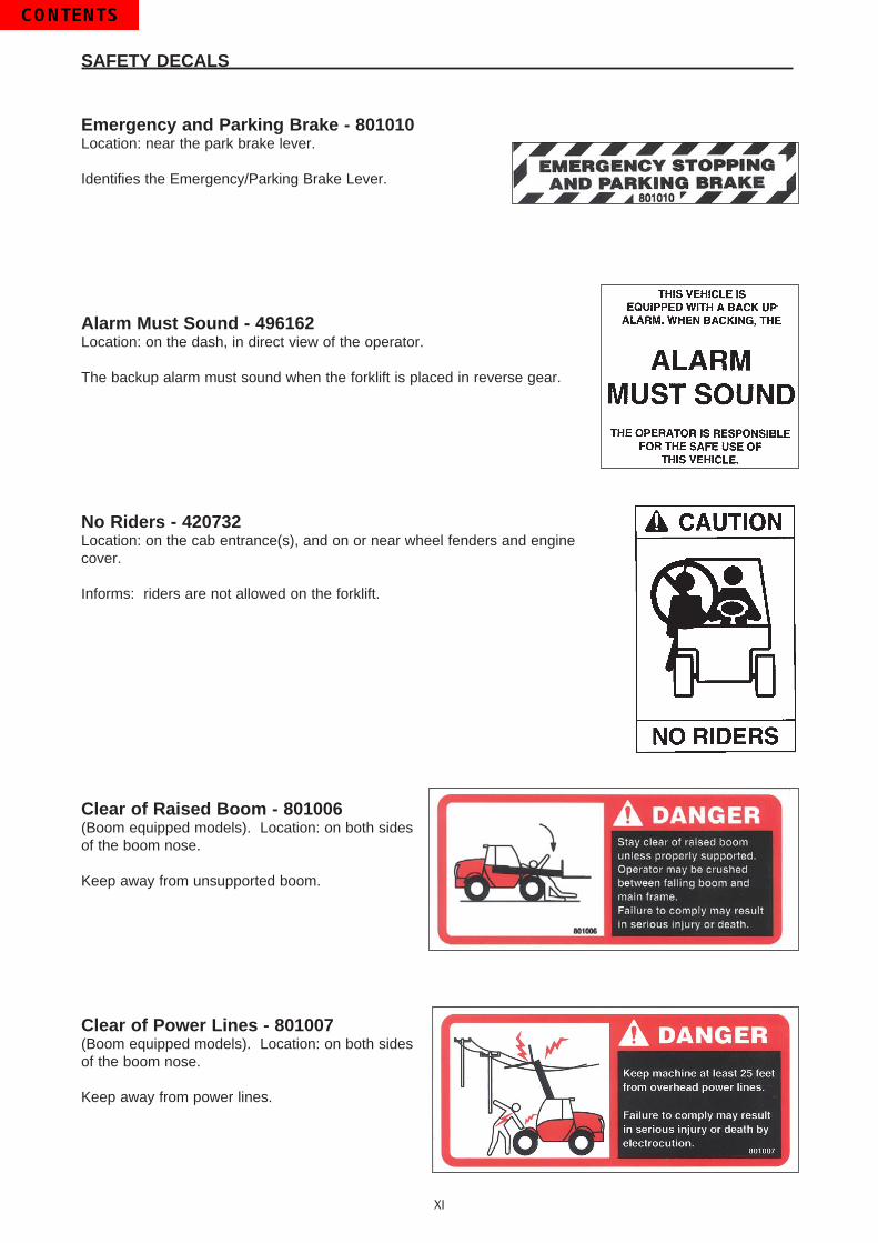
Emergency and Parking Brake - 801010Location: near the park brake lever.
Identifies the Emergency/Parking Brake Lever.
Alarm Must Sound - 496162Location: on the dash, in direct view of the operator.
The backup alarm must sound when the forklift is placed in reverse gear.
No Riders - 420732Location: on the cab entrance(s), and on or near wheel fenders and engine cover.
Informs: riders are not allowed on the forklift.
Clear of Raised Boom - 801006(Boom equipped models). Location: on both sides of the boom nose.
Keep away from unsupported boom.
Clear of Power Lines - 801007(Boom equipped models). Location: on both sides of the boom nose.
Keep away from power lines.
XI

SAFETY DECALS
Use of Frame Leveling - 801013(Boom equipped models). Location: to the right of the operator near the hydraulic control lever.
Frame leveling notice; load must be lowered.
Attachment and Boom Safety - 801009(Boom equipped models). Location: on both sides of the boom nose.
Important reminders of attachment and boom safety.
Hydraulic Coupling - 234805Location: near the quick-disconnect adapters.
Stop the engine and release hydraulic pressure before changing attachments.
Rotating Fan and Belt(s) - 801008Location: on the radiator near the fan, and on any fan belt/pulley cover(s).
Keep hands and clothing away from rotating fan and belts.
XII

SAFETY DECALS
Gear Shift Pattern - 33460(4-speed transmission models). Location: near the gear shift lever.
Identifies the gear shift pattern of the forklift transmission.
Steering Mode - 184276(4 wheel steer equipped models). Location: near the steering mode selection lever.
Identifies the steering mode selection.
Mineral Oil (Brake Reservoir) - 221322 or 234800 has been replaced by 164091.Location: near the brake fluid reservoir where applicable.
Refer to the Operator/Service Manual for the correct brake fluid(mineral oil) to be used in the brake system.
XIII
221322
234800

SAFETY DECALS
Hydraulic Oil - 234798 or 76573Location: on the hydraulic tank or filler cap.
Identifies the hydraulic reservoir (tank) or filler cap.
Hydraulic Oil - 61024Location: on the hydraulic tank.
Identifies the hydraulic reservoir (tank).
Anti-Freeze - 234799Location: on the radiator, near the radiator filler cap.
Indicates required minimum to maximum anti-freeze protection (-220F to -400F).
Diesel Fuel - 161101Location: on the fuel tank, near the filler cap.
Identifies the fuel tank, and use of diesel fuel.
No Step - 496735Location: varies, depending on the forklift model.
Instructs personnel not to use the designated area as a step.
Do Not Tow - 494918(Hydrostatic equipped models). Location: on the dash, in view of the operator.
Towing the forklift will damage the transmission; refer to the operator’s manual.
XIV
SAFETY DECALS
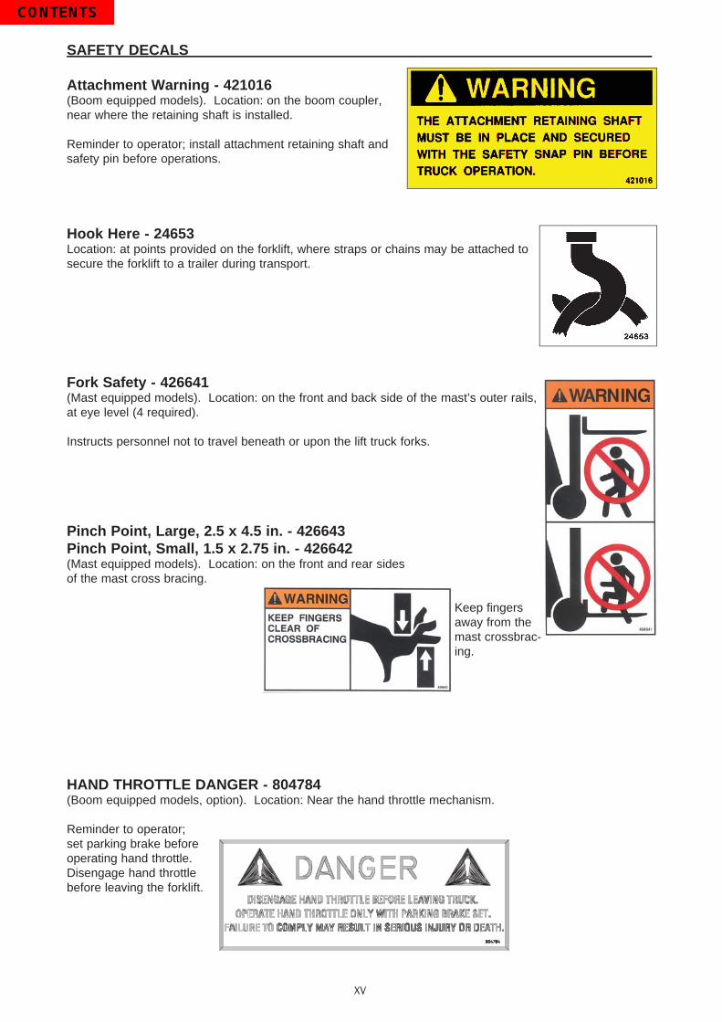
Attachment Warning - 421016(Boom equipped models). Location: on the boom coupler, near where the retaining shaft is installed.
Reminder to operator; install attachment retaining shaft and safety pin before operations.
Hook Here - 24653Location: at points provided on the forklift, where straps or chains may be attached to secure the forklift to a trailer during transport.
Fork Safety - 426641(Mast equipped models). Location: on the front and back side of the mast’s outer rails, at eye level (4 required).
Instructs personnel not to travel beneath or upon the lift truck forks.
Pinch Point, Large, 2.5 x 4.5 in. - 426643Pinch Point, Small, 1.5 x 2.75 in. - 426642(Mast equipped models). Location: on the front and rear sidesof the mast cross bracing.
Keep fingers away from the mast crossbrac-ing.
HAND THROTTLE DANGER - 804784(Boom equipped models, option). Location: Near the hand throttle mechanism.
Reminder to operator; set parking brake before operating hand throttle.Disengage hand throttle before leaving the forklift.
XV

SAFETY DECALS
Acid in Battery - 801014Location: in or near the batterystorage compartment.
Addresses battery hazards.
Jump Start Battery - 801015Location: in or near the battery storage compartment.
Jump start instructions.
Attachment Plate - 425995Location: on the optional removeable forklift attachment.
Important manufacturer information about the attachment. Record this information for use when contacting the maufacturer for parts and service.
Overhead Guard Data Plate - B6109Location: attached to the overhead guard.
Overhead guard conformity.
Forklift Data Plate - 496550(Boom equipped models)Forklift Data Plate - 496538(Mast equipped models)Location: within the operator’s compartment.
Important forklift truck identification. Record this information for use when contacting the manufacturer for parts and service.
XVI
496550 496538

1 - OPERATING AND SAFETY INSTRUCTIONS
2 - DESCRIPTION
3 - MAINTENANCE

1-1
1 - OPERATING AND SAFETY INSTRUCTIONS

1-2

1-3
TABLE OF CONTENTS
INSTRUCTIONS TO THE COMPANY MANAGER
THE OPERATORTHE LIFT TRUCK
A - THE LIFT TRUCK’S SUITABILITY FOR THE JOBB - ADAPTATION OF THE LIFT TRUCK TO STANDARD ENVIRONMENTAL CONDITIONSC - MODIFICATION OF THE LIFT TRUCK
THE INSTRUCTIONSTHE MAINTENANCE
INSTRUCTIONS FOR THE OPERATOR
PREAMBLEGENERAL INSTRUCTIONS
A - OPERATOR’S MANUALB - AUTHORIZATION FOR USEC - MAINTENANCED - MODIFICATION OF THE LIFT TRUCKE - LIFTING PEOPLE
OPERATING INSTRUCTIONS UNLADEN AND LADENA - BEFORE STARTING THE LIFT TRUCKB - DRIVER’S OPERATING INSTRUCTIONSC - ENVIRONMENTD - VISIBILITYE - STARTING THE LIFT TRUCKF - DRIVING THE LIFT TRUCKG - STOPPING THE LIFT TRUCKH - DRIVING THE LIFT TRUCK ON THE PUBLIC HIGHWAY
INSTRUCTIONS FOR HANDLING A LOADA - CHOICE OF ATTACHMENTSB - MASS OF LOAD AND CENTER OF GRAVITYC - TRANSVERSE ATTITUDE OF THE LIFT TRUCKD - TAKING UP A LOAD ON THE GROUNDE - TAKING UP AND LAYING A HIGH LOAD ON TIRES
MAINTENANCE INSTRUCTIONS OF THE LIFT TRUCK
GENERAL INSTRUCTIONSMAINTENANCELUBRICANT AND FUEL LEVELSHYDRAULICELECTRICITYWELDINGWASHING THE LIFT TRUCK
IF THE LIFT TRUCK IS NOT TO BE USED FOR A LONG TIME
INTRODUCTIONPREPARING THE LIFT TRUCKPROTECTING THE I.C. ENGINEPROTECTING THE LIFT TRUCKBRINGING THE LIFT TRUCK BACK INTO SERVICE
1 - 4
1 - 41 - 41 - 41 - 41 - 51 - 51 - 5
1 - 6
1 - 61 - 61 - 61 - 61 - 61 - 61 - 61 - 81 - 81 - 81 - 91 - 9
1 - 101 - 101 - 111 - 121 - 131 - 131 - 131 - 141 - 141 - 15
1 - 16
1 - 161 - 161 - 161 - 161 - 161 - 171 - 17
1 - 18
1 - 181 - 181 - 181 - 181 - 19

1-4
INSTRUCTIONS TO THE COMPANY MANAGER
THE OPERATOR
- Only qualified, authorized personnel can use the lift truck. This authorization is given in writing by the appropriate person in the establishment with respect to the use of lift trucks and must be carried permanently by the operator.
On the basis of experience, there are a number of possible situations in which operating the lift truck is prohibited. Such fore-seeable abnormal uses, the main ones being listed below, are strictly forbidden.- The foreseeable abnormal behavior of neglect, but not intending to put the machinery to any improper use.- The reflex reactions of a person in the event of a malfunction, incident, fault, etc. During operation of the lift truck.- Behavior resulting from application of the “principle of least action” when performing a task.- For certain machines, the foreseeable behavior of such persons as unauthorized: apprentices, teenagers, handicapped
persons and trainees tempted to drive a lift truck. Truck drivers tempted to operate a truck to win a bet, in competition or for their own personal experience.
The person in charge of the equipment must take these criteria into account when assessing whether or not a person will make a suitable driver.
WARNING
THE LIFT TRUCK
A - THE LIFT TRUCK’S SUITABILITY FOR THE JOB- MANITOU has ensured that this lift truck is suitable for use under the standard operating conditions defined in this operator’s manual, with a STATIC TEST COEFFICIENT OF 1.33 and a DYNAMIC TEST COEFFICIENT OF 1, as specified in harmonized norm EN 1726-1 for mast trucks.
- Before commissioning, the company manager must make sure that the lift truck is appropriate for the work to be done, and perform certain tests (in accordance with current legislation).
B - ADAPTATION OF THE LIFT TRUCK TO STANDARD ENVIRONMENTAL CONDITIONS- In addition to series equipment mounted on your lift truck, many options are available, such as: road lighting, stop lights, flashing light, reverse lights, reverse buzzer alarm, front light, rear light, etc.
- The operator must take into account the operating conditions to define the lift truck’s signalling and lighting equipment. Contact your dealer.
- Take into account climatic and atmospheric conditions of the site of utilization.. Protection against frost (see: 3 - MAINTENANCE: LUBRICANTS AND FUEL).. Adaptation of lubricants (ask your dealer for information).. I.C. engine filtration (see: 3 - MAINTENANCE: FILTERS CARTRIDGES AND BELTS).
For operation under average climatic conditions, i.e. between -15 °C and + 35 °C (5° to 95°F), correct levels of lubricants in all the circuits are provided in production. For operation under more severe climatic conditions, before starting up, it is necessary to drain all the circuits, then add the correct levels of lubri-cants properly suited to the relevant ambient temperatures. It is the same for the cooling fluid (Contact
your dealer for information, if necessary).
IMPORTANT
- A lift truck operating in an area without fire extinguishing equipment must be equipped with an individual extinguisher. There are solutions, consult your dealer.
Your lift truck is designed for outdoor use under normal atmospheric conditions and indoor use in suitably aerated and ventilated premises. It is prohibited to use the lift truck in areas where there is a risk of fire or which are potentially explosive (i.e. refineries, fuel or gas depots, stores of inflammable products…). For use in these areas, specific equipment is available (ask your dealer for information).
WARNING
- Our trucks comply with Directive 89/336/EC concerning electromagnetic compatibility (EMC), and with the corresponding harmonized norm EN 12895. Their proper operation is no longer guaranteed if they are used within areas in which the electromagnetic fields exceed the limit specified by that norm (10 V/m).
- Directive 2002/44/EC requires company managers to not expose their employees to excessive vibration doses. There is no recognized code of measurement for comparing the machines of different manufacturers. The actual doses received can therefore be measured only under actual operating conditions at the user’s premises.
- The following are some tips for minimizing these vibration doses:• Select the most suitable lift truck and attachment for the intended use.• Adapt the seat adjustment to the operator’s weight (according to lift truck model) and maintain it in good condition, as
well as the cab suspension. Inflate the tires in accordance with recommendations.• Ensure that the operators adapt their operating speed to suit the conditions on site.• As far as possible, arrange the site in such a way as to provide a flat running surface and remove obstacles and harmful
potholes.
1-5
C - MODIFICATION OF THE LIFT TRUCK- For your safety and that of others, you must not change the structure and settings of the various components used in your lift truck (hydraulic pressure, calibrating limiters, I.C. engine speed, addition of extra equipment, addition of counterweight, unapproved attachments, alarm systems, etc.) yourself. In this event, the manufacturer cannot be held responsible.
THE INSTRUCTIONS
- The operator’s manual must always be in good condition and kept in the place provided on the lift truck and in the language used by the operator.
- The operator’s manual and any plates or decals which are no longer legible or are damaged, must be replaced immediately.
THE MAINTENANCE
- Maintenance or repairs other than those detailed in part: 3 - MAINTENANCE must be carried out by qualified personnel (consult your dealer) and under the necessary safety conditions to maintain the health of the operator and any third party.
Your lift truck must be inspected periodically to ensure that it remains in compliance. The frequency of this inspection is defined by current legislation in the country in which the lift truck is used.
WARNING

1-6
INSTRUCTIONS FOR THE OPERATOR
PREAMBLE
The risk of accident while operating, servicing or repairing your lift truck can be reduced if you follow the safety instructions and safety measures detailed in this manual. Failure to respect the safety and operating instructions, or the instructions for repairing or servicing your lift truck can lead to serious injury or fatal accident.
DANGER
- Only the operations and maneuvers described in these operator’s manual must be performed. The manufacturer cannot predict all possible risky situations. Consequently, the safety instructions given in the operator’s manual and on the lift truck itself are not all inclusive.
- At any time, as an operator, you must envision, within reason, the possible risk to yourself, to others or to the lift truck itself when you use it.
GENERAL INSTRUCTIONS
A - OPERATOR’S MANUAL- Read the operator’s manual carefully.- The operator’s manual must always be in good condition and in the place provided for it on the lift truck.- You must report any plates and decals which are no longer legible or which are damaged.
B - AUTHORIZATION FOR USE
- Only qualified, authorized personnel may use the lift truck. This authorization is given in writing by the appropriate person in the company, in charge of using the lift truck, and must be permanently carried by the operator.
- The operator is not competent to authorize the driving of the lift truck by another person.
C - MAINTENANCE- The operator must immediately advise his superior if his lift truck is not in good working order or does not comply with the safety notice.
- The operator is prohibited from carrying out any repairs or adjustments himself, unless he has been trained for this purpose. He must keep the lift truck properly cleaned if this is among his responsibilities.
- The operator must carry out daily maintenance (see: 3 - MAINTENANCE: A - DAILY OR EVERY 10 HOURS SERVICE).- The operator must ensure tires are adapted to the nature of the ground (see area of the contact surface of the tires in the chapter: 2 - DESCRIPTION: FRONT AND REAR TIRES). There are optional solutions, consult your dealer.
. SAND tires.
. LAND tires.
. Snow chains.
Do not operate the lift truck if the tires are incorrectly inflated, damaged or excessively worn, Bad tires can put your safety or that of others at risk, or cause damage to the lift truck. The installation of foam inflated tires is prohibited and is not guaranteed by the manufacturer (prior authorization is required).
DANGER
D - MODIFICATION OF THE LIFT TRUCK- For your safety and that of others, you must not change the structure and settings of the various components used in your lift truck (hydraulic pressure, calibrating limiters, I.C. engine speed, addition of extra equipment, addition of counterweight, unapproved attachments, alarm systems, etc.) yourself. In this event, the manufacturer cannot be held responsible.
E - LIFTING PEOPLE- The use of working equipment and load lifting attachments to lift people is strictly forbidden.

1-7

1-8
OPERATING INSTRUCTIONS UNLADEN AND LADEN
A - BEFORE STARTING THE LIFT TRUCK- Carry out daily maintenance (see: 3 - MAINTENANCE: A - DAILY OR EVERY 10 HOURS SERVICE).- Make sure the lights, indicators and windscreen wipers are working properly.- Make sure the rear view mirrors are in good condition, clean and properly adjusted.- Make sure the horn and backup alarm work properly.
B - DRIVER’S OPERATING INSTRUCTIONS- Whatever his experience, the operator is advised to familiarize himself with the position and operation of all the controls and instruments before operating the lift truck.
- Wear clothes suited for driving the lift truck, avoid loose clothes.- Make sure you have the appropriate protective equipment for the job to be done.- Prolonged exposure to high noise levels may cause hearing problems. It is recommended to wear ear muffs to protect against excessive noise.
- Always face the lift truck when getting into and leaving the driving seat and use the handle(s) provided for this purpose. Do not jump out of the seat to get down.
- Always pay attention when using the lift truck. Do not listen to the radio or music using headphones or earphones.- Never operate the lift truck when hands or feet are wet or soiled with greasy substances.- For increased comfort, adjust the seat to your requirements and adopt the correct position in the driver’s cab.
Under no circumstances should the seat be adjusted while the lift truck is moving.CAUTION
- The operator must always be in his normal position in the driver’s cab. It is prohibited to have arms or legs, or generally any part of the body, protruding from the driver’s cab of the lift truck.
- The safety belt must be worn and adjusted to the operator’s size.- The control units must never in any event be used for any other than their intended purposes (e.g. climbing onto or down from the lift truck cab, etc.).
- If the control components are fitted with a forced operation (lever lock) device, it is forbidden to leave the cab without first putting these controls in neutral.
- It is prohibited to carry passengers either on the lift truck or in the cab.

1-9
C - ENVIRONMENT- Comply with site safety regulations.- If you have to use the lift truck in a dark area or at night, make sure it is equipped with working lights.- During handling operations, make sure that no one is in the way of the lift truck and its load.- Do not allow anybody to come near the working area of the lift truck or pass beneath an elevated load.- When using the lift truck on a transverse slope, before lifting the mast, follow the instructions given in the paragraph: INSTRUCTIONS FOR HANDLING A LOAD: C - TRANSVERSE ATTITUDE OF THE LIFT TRUCK.
- Traveling on a longitudinal slope:• Drive and brake gently.
• Moving without load: Forks or attachment facing downhill.
• Moving with load: Forks or attachment facing uphill. - Take into account the lift truck’s dimensions and its load before trying to negotiate a narrow or low passageway.- Never move onto a loading platform without having first checked:
• That it is suitably positioned and made fast.• That the unit to which it is connected (tractor, truck, etc.) will not shift.• That this platform is prescribed for the total weight of the lift truck to be loaded.• That this platform is prescribed for the size of the lift truck.
- Never move onto a foot bridge, floor or freight lift, without being certain that they are prescribed for the weight and size of the lift truck to be loaded and without having checked that they are in sound working order.
- Be careful in the area of loading bays, trenches, scaffolding, soft ground and manholes.- Make sure the ground is stable and firm under the wheels before lifting the load.- Make sure that the scaffolding, loading platform, pilings or ground is capable of bearing the load.- Never stack loads on uneven ground, they may tip over.- The load or the attachment must not be left just above a structure for long periods at a time because of the descending mast. In such a case, a constant watch must be kept and the height of the forks or the attachment readjusted if necessary.
- When working near aerial lines, ensure that the safety distance is sufficient between the working area of the lift truck and the aerial line.
You must consult your local electrical agency. You could be electrocuted or seriously injured if you operate or park the lift truck too close to power lines.DANGER
During high winds do not attempt moving loads that may catch the wind or cause the fork lift to be unstable.DANGER
D - VISIBILITY- The safety of people within the lift truck’s working area, as well as that of the lift truck itself and the operator are dependent on good operator visibility of the lift truck’s immediate vicinity in all situations and at all times.
- This lift truck has been designed to allow good operator visibility (direct or indirect by means of rear-view mirrors) of the immediate vicinity of the lift truck while traveling with no load and with the mast in the transport position.
- Special precautions must be taken if the size of the load restricts visibility towards the front:- moving in reverse,- site layout,- assisted by a person directing the maneuver (while standing outside the truck’s area of travel), making sure to keep this person clearly in view at all times,
- in any case, avoid reversing over long distances.- If visibility of your road is inadequate, ask someone to assist by directing the maneuver (while standing outside the truck’s area of travel), making sure to keep this person clearly in view at all times.
- Keep all components affecting visibility in a clean, properly adjusted state and in good working order (e.g. windscreens, windows, windscreen wipers, windscreen washers, driving and work lights, rear-view mirrors).

1-10
E - STARTING THE LIFT TRUCKSAFETY NOTICE
The lift truck must be started or maneuvered only when the operator is sitting in the driver’s cab, his seat belt fastened and properly adjusted.
WARNING- Never try to start the lift truck by pushing or towing it. Such operation may cause severe damage to the transmission. If necessary, to tow the lift truck in an emergency, the transmission must be placed in the neutral position (see: 3 - MAINTENANCE: G - OCCASIONAL MAINTENANCE).
- If using an emergency battery for start-up, use a battery with the same characteristics and respect battery polarity when connecting it. Connect at first the positive terminals before the negative terminals.
Failure to respect polarity between batteries can cause serious damage to the electrical circuit. The electrolyte in the battery may produce an explosive gas. Avoid flames and generation of sparks close to the batteries. Never disconnect a battery while it is charging.
WARNING
INSTRUCTIONS- Check the closing and locking of the hood(s).- For lift trucks operating on gas carburization, open the gas bottle.- Check that the forward/reverse selector is in neutral.- Turn the ignition key to the position I to activate the electrical system and the preheat.- Check the fuel level on the indicator.- Turn the ignition key fully: the I.C. engine should then start. Release the ignition key and let the I.C. engine run at idle.- Do not engage the starter motor for more than 15 seconds and carry out the preheating between unsuccessful attempts.- Make sure all the signal lights on the control instrument panel function correctly.- Check all control instruments when the I.C. engine is warm and at regular intervals during use, so as to quickly detect any problems and to be able to correct them without any delay.
- If an instrument does not show the correct display, stop the I.C. engine and immediately carry out the necessary operations.
F - DRIVING THE LIFT TRUCKSAFETY NOTICE
Operators’ attention is drawn to the risks involved in using the lift truck, in particular : - Risk of losing control. - Risk of losing lateral and frontal stability of the lift truck.The operator must remain in control of the lift truck. In the event of the lift truck overturning, do not try to leave the cab during the incident. YOUR BEST PROTECTION IS TO STAY FASTENED IN THE CAB.
DANGER
- Observe the company’s traffic regulations or, by default, the public highway code.- Do not carry out operations which exceed the capacities of your lift truck or attachments.- Always drive the lift truck with the forks or attachment in the transport position, i.e. at 12 in. from the ground and the carriage sloping backwards.
- Only carry loads which are balanced and properly anchored to avoid any risk of a load falling off.- Ensure that pallets, cases, etc, are in good order and suitable for the load to be lifted.- Familiarize yourself with the lift truck on the terrain where it will be used.- Ensure that the service brakes are working properly.- The loaded lift truck must not travel at speeds in excess of 7 mph.- Drive smoothly at an appropriate speed for the operating conditions (land configuration, load on the lift truck).- Do not use the hydraulic mast controls when the lift truck is moving.- Do not maneuver the lift truck with the mast in the raised position unless under exceptional circumstances and then with extreme caution, at very low speed and using gentle braking. Ensure that visibility is adequate.
- Take turns slowly.- In all circumstances make sure you are in control of your speed.- On damp, slippery or uneven terrain, drive slowly.- Brake gently, never abruptly.- Only use the lift truck’s forward/reverse selector from a stationary position and never do so abruptly.- Do not drive with your foot on the brake pedal.- Always remember that hydrostatic type steering is extremely sensitive to movement of the steering wheel, so turn it gently and not abruptly.
- Never leave the I.C. engine on when the lift truck is unattended.- Do not leave the cab when the lift truck has a raised load.- Look where you are going and always make sure you have good visibility along the route.

1-11
- Use the rear-view mirrors frequently.- Drive around obstacles.- Never drive on the edge of a ditch or steep slope.- It is dangerous to use two lift trucks simultaneously to handle heavy or large loads, since this operation requires particular precautions to be taken. It must only be used exceptionally and after risk analysis.
- The ignition switch has an emergency stop mechanism in case of an operating anomaly occurring in the case of lift trucks not fitted with a punch-operated cut-out.
INSTRUCTIONS- Always drive the lift truck with the forks or attachment to the transport position, i.e. at 12 in. from the ground and the carriage sloping backwards.
- For lift trucks with gearboxes, use the recommended gear (see: 2 - DESCRIPTION: INSTRUMENTS AND CONTROLS).- Release the parking brake.- Shift the forward/reverse selector to the selected direction of travel and accelerate gradually until the lift truck moves off.
G - STOPPING THE LIFT TRUCKSAFETY NOTICE- Never leave the ignition key in the lift truck during the operator’s absence.- When the lift truck is stationary, or if the operator has to leave his cab (even for a moment), place the forks or attachment on the ground, apply the parking brake and put the forward/reverse selector in neutral.
- Make sure that the lift truck is not stopped in any position that will interfere with the traffic flow and at least six feet from the track of a railway.
- In the event of prolonged parking on a site, protect the lift truck from bad weather, particularly from frost (check the level of antifreeze), close and lock all the lift truck accesses (doors, windows, cowls…).
INSTRUCTIONS- Park the lift truck on flat ground or on an incline less than 15 %.- Place the forward/reverse selector in neutral.- Apply the parking brake.- For lift trucks with gearboxes, place the gear lever in neutral.- Lower the forks or attachment to rest on the ground.- When using an attachment with a grab or jaws, or a bucket with hydraulic opening, close the attachment fully.- Before stopping the lift truck after a long working period, leave the I.C. engine idling for a few moments, to allow the coolant liquid and oil to lower the temperature of the I.C. engine and transmission. Do not forget this precaution, in the event of frequent stops or warm stalling of the I.C. engine, or else the temperature of certain parts will rise significantly due to the stopping of the cooling system, with the risk of badly damaging such parts.
- Stop the I.C. engine with the ignition switch.- Remove the ignition key.- Lock all the accesses to the lift truck (doors, windows, cowls…).- For lift trucks operating on gas carburization, shut the LPG bottle. For a long lasting stop, let the engine stop naturally by shutting the LPG bottle before switching off the ignition, so as to eliminate all the fuel in the feed tube.
1-12
H - DRIVING THE LIFT TRUCK ON THE PUBLIC HIGHWAYSAFETY INSTRUCTIONS- Operators driving on the public highway must comply with current highway code legislation.- The lift truck must comply with current road legislation. If necessary, there are optional solutions. Contact your dealer.
INSTRUCTIONS- Make sure the revolving light is in place, switch it on and verify its operation.- Check the good working order and cleanliness of lights, indicators and windscreen wiper.- Switch off the working headlights if the lift truck is fitted with them.- Put the attachment at 12 in. from the ground.- For lift trucks with gearboxes:On the road, set off in 3rd gear and go into 4th (as model of lift truck) when the conditions and state of the road allow. In hilly areas, set off in 2nd gear and go into 3rd when the conditions and state of the road allow.
Do not allow the lift truck to coast in neutral (using either the forward/reverse lever, gear shift lever or transmission cut-off button). Coasting on a slope will lead to excessive speed which may make the lift truck uncontrollable (steering, brakes) and may cause serious mechanical damage.
DANGER
DRIVING THE LIFT TRUCK WITH A FRONT-MOUNTED ATTACHMENT- You must comply with current regulations in your country, covering the possibility of driving on the public highway with a front-mounted attachment on your lift truck.
- If road legislation in your country authorizes circulation with a front-mounted attachment, you must at least:• Protect and report any sharp and/or dangerous edges on the attachment (see: 4 - ADAPTABLE ATTACHMENTS IN OPTION
ON THE RANGE: ATTACHMENT SHIELDS).• The attachment must not be loaded.• Make sure that the attachment does not mask the lighting range of the forward lights.• Make sure that current legislation in your country does not require other obligations.
OPERATING THE LIFT TRUCK WITH A TRAILER- For using a trailer, observe the regulations in force in your country (maximum travel speed, braking, maximum weight of trailer, etc.).
- Do not forget to connect the trailer’s electrical equipment to that of the lift truck.- The trailer’s braking system must comply with current legislation.- If pulling a trailer with assisted braking, the tractor lift truck must be equipped with a trailer braking mechanism. In this case, do not forget to connect the trailer braking equipment to the lift truck.
- The maximum vertical pull on the trailer hook must not exceed 650 ft/lb.- The authorized maximum train weight must not exceed the maximum weight authorized by the manufacturer (consult the manufacturer’s plate on your lift truck).
- For lift trucks with gearboxes:When driving with a trailer, set off in 2nd gear and go into 3rd when the conditions and state of the road allow. Do not exceed 4th gear to avoid overheating the internal combustion engine and the transmission.
IF NECESSARY, CONSULT YOUR DEALER.

1-13
INSTRUCTIONS FOR HANDLING A LOAD
A - CHOICE OF ATTACHMENTS- Only attachments approved by MANITOU can be used on its lift trucks.- Make sure the attachment is appropriate for the work to be done (see: 4 - ADAPTABLE ATTACHMENTS IN OPTION ON THE RANGE).
- Make sure the attachment is correctly installed and locked onto the lift truck carriage.- Make sure that your lift truck attachments work properly.- Comply with the load chart limits for the lift truck for the attachment used.- Do not exceed the rated capacity of the attachment.- Never lift a load in a sling without the attachment provided for the purpose. There are optional solutions ; contact your dealer.
B - MASS OF LOAD AND CENTER OF GRAVITY- Before taking up a load, you must know its mass and its center of gravity.- The load chart for your lift truck is valid for a load in which the longitudinal position of the center of gravity is 24 in. from the base of the forks (as model of lift truck) (fig. B1). For a higher center of gravity, contact your dealer.
- For irregular loads, determine the transverse center of gravity before any movement (fig. B2) and set it in the longitudinal axis of the lift truck.
CAUTION
Do not attempt to move a load heavier than the effective capacity defined on the lift truck load chart.
CAUTIONFor loads with a moving center of gravity (i.e., liquids), take into account the varia-tions of the center of gravity in order to determine the load to be handled (Consult your agent or dealer). Be vigilant and take extra care to limit these variations as much as possible.
500 mm
B1
B2
24 in.
1-14
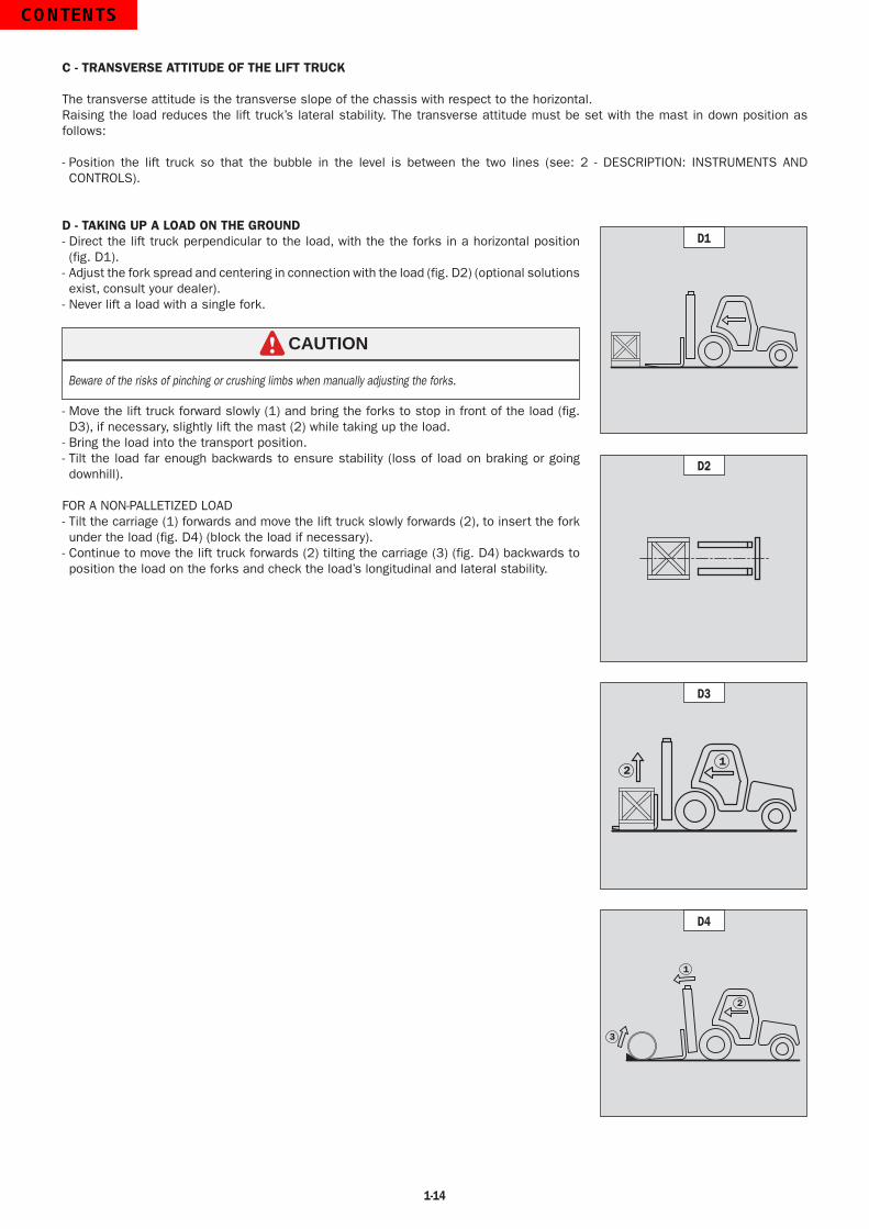
C - TRANSVERSE ATTITUDE OF THE LIFT TRUCK
The transverse attitude is the transverse slope of the chassis with respect to the horizontal.Raising the load reduces the lift truck’s lateral stability. The transverse attitude must be set with the mast in down position as follows:
- Position the lift truck so that the bubble in the level is between the two lines (see: 2 - DESCRIPTION: INSTRUMENTS AND CONTROLS).
D - TAKING UP A LOAD ON THE GROUND- Direct the lift truck perpendicular to the load, with the the forks in a horizontal position (fig. D1).
- Adjust the fork spread and centering in connection with the load (fig. D2) (optional solutions exist, consult your dealer).
- Never lift a load with a single fork.
CAUTION
Beware of the risks of pinching or crushing limbs when manually adjusting the forks.
- Move the lift truck forward slowly (1) and bring the forks to stop in front of the load (fig. D3), if necessary, slightly lift the mast (2) while taking up the load.
- Bring the load into the transport position.- Tilt the load far enough backwards to ensure stability (loss of load on braking or going downhill).
FOR A NON-PALLETIZED LOAD- Tilt the carriage (1) forwards and move the lift truck slowly forwards (2), to insert the fork under the load (fig. D4) (block the load if necessary).
- Continue to move the lift truck forwards (2) tilting the carriage (3) (fig. D4) backwards to position the load on the forks and check the load’s longitudinal and lateral stability.
D1
D2
12
D3
3
1
2
D4

1-15
E - TAKING UP AND LAYING A HIGH LOAD ON TIRES
WARNINGDo not raise the mast until you have first checked the level attitude of the lift truck (see : INSTRUCTIONS FOR HANDLING A LOAD : D - TRANSVERSE ATTITUDE OF THE LIFT TRUCK).
REMINDER: Make sure that the following operations can be performed with good visibility (see: OPERATIONS INSTRUCTIONS UNLADEN AND LADEN: D - VISIBILITY).
TAKING UP A HIGH LOAD ON TIRES- Ensure that the forks will easily pass under the load.- Keeping the mast vertical (1), advance the lift truck and raise the forks to level with the load (2) (fig. E1).
- Maneuver carefully and gently to bring the forks to stop in front of the load (fig. E2). Put the handbrake on and set the forward/reverse selector to neutral.
- Slightly lift the load (1) and incline the carriage (2) backwards to stabilize the load (fig. E3).
- Tilt the load sufficiently backwards to ensure its stability.- Release the hand brake. Reverse the lift truck (1) very carefully and gently to free the load. Lower the mast (2) to bring the load into transport position (fig. E4).
LAYING A HIGH LOAD ON TIRES- Arrange the load in the transport position in front of the pile (fig. E5).- Raise the mast (1) until the load is higher than the pile and move the lift truck forward (2) (fig. E6) very carefully and gently, until the load is over the pile. Put the handbrake on and set the forward/reverse selector to neutral.
- Place the load in a horizontal position by tilting the mast forwards (1) and lay it down on the pile (2) while checking the correct positioning of the load (fig. E7).
- Release the hand brake. Reverse the lift truck (1) very slowly and carefully to release the forks (fig. E8). Then set them into transport position.
1
2
E1
E2
1
2
E4
1
2
E3
E5
1
E81
2
E7
2
1
E6

1-16
MAINTENANCE INSTRUCTIONS OF THE LIFT TRUCK
GENERAL INSTRUCTIONS
- Ensure the area is sufficiently ventilated before starting the lift truck.- Wear clothes suitable for the maintenance of the lift truck, avoid wearing jewelery and loose clothes. Tie and protect your hair, if necessary.
- Stop the I.C. engine and remove the ignition key, when an intervention is necessary.- Read the operator’s manual carefully.- Carry out all repairs immediately, even if the repairs concerned are minor.- Repair all leaks immediately, even if the leak concerned is minor.- Make sure that the disposal of process materials and of spare parts is carried out in total safety and in a ecological way.- Beware of the risk of burning and splashing (exhaust, radiator, I.C. engine, etc.).
MAINTENANCE
- Perform the periodic service (see: 3 - MAINTENANCE) to keep your lift truck in good working conditions. Failure to perform the periodic service may cancel the contractual guarantee.
MAINTENANCE LOGBOOK- The maintenance operations carried out in accordance with the recommendations given in part: 3 - MAINTENANCE and the other inspection, servicing or repair operations or modifications performed on the lift truck or its attachments shall be recorded in a maintenance logbook. The entry for each operation shall include details of the date of the works, the names of the individuals or companies having performed them, the type of operation and its frequency, if applicable. The part numbers of any lift truck items replaced shall also be indicated.
LUBRICANT AND FUEL LEVELS
- Use the recommended lubricants (never use contaminated lubricants).- Do not fill the fuel tank when the I.C. engine is running.- Only fill up the fuel tank in areas specified for this purpose.- Do not fill the fuel tank to the maximum level.- Do not smoke or approach the lift truck with a flame, when the fuel tank is open or is being filled.
HYDRAULIC
- Any work on the load handling hydraulic circuit is forbidden except for the operations described in part: 3 - MAINTENANCE.- Do not attempt to loosen unions, hoses or any hydraulic component with the circuit under pressure.
BALANCING VALVE : It is dangerous to change the setting or remove the balancing valves or safety valves which may be fitted to your lift truck cylinders. These operations must only be performed by approved personnel (consult your dealer).
WARNING
The HYDRAULIC ACCUMULATORS which may be fitted on your lift truck, are under high pressure, it is dangerous to dismantle them. This operation must only be performed by approved personnel (consult your dealer).
WARNING
ELECTRICITY
Do not short-circuit the starter relay to start the lift truck. If the forward/reverse gear is not in neutral, the lift truck will start to move immediately!
DANGER
- Do not drop metallic items on the battery.- Disconnect the battery before working on the electrical circuit.
1-17
WELDING
- Disconnect the battery before any welding operations on the lift truck.- When carrying out electric welding work on the lift truck, connect the negative cable from the equipment directly to the part being welded, so as to avoid high tension current passing through the alternator.
- Never carry out welding or work which gives off heat on an assembled tire. The heat would increase the pressure which could cause the tire to explode.
- If the lift truck is equipped with an electronic control unit, disconnect this before starting to weld, to avoid the risk of causing irreparable damage to electronic components.
WASHING THE LIFT TRUCK
- Clean the lift truck or at least the area concerned before any intervention.- Remember to close and lock all accesses to the lift truck (doors, windows, cowls…).- During washing, avoid the articulations and electrical components and connections.- If necessary, protect against penetration of water, steam or cleaning agents, components susceptible of being damaged, particularly electrical components and connections and the injection pump.
- Clean the lift truck of any fuel, oil or grease trace.
FOR ANY INTERVENTION OTHER THAN REGULAR MAINTENANCE, CONSULT YOUR DEALER.

1-18
IF THE LIFT TRUCK IS NOT TO BE USED FOR A LONG TIME
INTRODUCTION
The following recommendations are intended to prevent the lift truck from being damaged when it is withdrawn from service for an extended period.For these operations, we recommend the use of protective products.Instructions for using the products are given on the packaging.
It is recommended that your dealer perform the following procedures for lift truck storage and returning it to service.IMPORTANT
PREPARING THE LIFT TRUCK
- Clean the lift truck thoroughly.- Check and repair any leakage of fuel, oil, water or air.- Replace or repair any worn or damaged parts.- Wash the painted surfaces of the lift truck in clear and cold water and dry them.- Touch up the paintwork if necessary.- Shut down the lift truck (see: OPERATING INSTRUCTIONS UNLADEN AND LADEN).- Make sure the mast cylinder rods are all in retracted position.- Release the pressure in the hydraulic circuits.
PROTECTING THE I.C. ENGINE
- Fill the tank with fuel (see: 3 - MAINTENANCE: A - DAILY OR EVERY 10 HOURS SERVICE).- Empty and replace the cooling liquid (see: 3 - MAINTENANCE: F - EVERY 2000 HOURS SERVICE).- Leave the I.C. engine running at idling speed for a few minutes, then switch off.- Replace the I.C. engine oil and oil filter (see: 3 - MAINTENANCE: D - EVERY 500 HOURS SERVICE).- Add a protective product to the engine oil.- Run the I.C. engine for a short time so that the oil and cooling liquid circulate inside.- Disconnect the battery and store it in a safe place away from the cold, after charging it to a maximum.- Remove the injectors and spray a protective product into each cylinder for two seconds with the piston in low neutral position.- Turn the crankshaft once slowly and install the injectors (see I.C. engine REPAIR MANUAL).- Remove the intake hose from the manifold or turbocharger and spray a protective product into the manifold or turbocharger.- Cap the intake manifold or turbocharger hole with waterproof adhesive tape.- Remove the exhaust pipe and spray a protective product into the exhaust manifold or turbocharger.- Install the exhaust pipe and block the outlet with waterproof adhesive tape.NOTE: The spray time is noted on the product packaging and must be increased by 50 % for turbo engines.- Open the filler plug, spray a protective product around the rocker arm shaft and install the filler plug.- Cap the fuel tank using waterproof adhesive tape.- Remove the drive belts and store them in a safe place.- Disconnect the engine cut-off solenoid on the injection pump and carefully insulate the connection.
PROTECTING THE LIFT TRUCK
- Set the lift truck on axle stands so that the tires are not in contact with the ground and release the handbrake.- Protect cylinder rods which will not be retracted, from corrosion.- Wrap the tires.NOTE: If the lift truck is to be stored outdoors, cover it with a waterproof tarpaulin.

1-19
BRINGING THE LIFT TRUCK BACK INTO SERVICE
- Remove the waterproof adhesive tape from all the holes.- Install the intake hose.- Install and reconnect the battery.- Remove the protection from the cylinder rods.- Perform the daily service (see: 3 - MAINTENANCE: A - DAILY OR EVERY 10 HOURS SERVICE).- Put the handbrake on and remove the axle stands.- Empty and replace the fuel and replace the fuel filter (see: 3 - MAINTENANCE: D - EVERY 500 HOURS SERVICE).- Install and set the tension in the drive belts (see: 3 - MAINTENANCE: C - EVERY 250 HOURS SERVICE).- Turn the I.C. engine using the starter, to allow the oil pressure to rise.- Reconnect the engine cut-off solenoid.- Lubricate the lift truck completely (see: 3 - MAINTENANCE: SERVICING SCHEDULE).
Insure the area is adequately ventilated before starting the lift truck.WARNING
- Start up the lift truck, following the safety instructions and regulations (see: OPERATING INSTRUCTIONS UNLADEN AND LADEN).- Run all the mast’s hydraulic movements, concentrating on the ends of travel for each cylinder.

1-20

2-1
2 - DESCRIPTION

2-2

2-3
TABLE OF CONTENTS
IDENTIFICATION OF THE LIFT TRUCK 2-4
CHARACTERISTICS MSI 30 T Series 2-E3 2-6
CHARACTERISTICS MH 25-4 T Series 2-E3 2-8
CHARACTERISTICS OF MASTS WITH ROLLERS MSI 30 T Series 2-E3 2-10
CHARACTERISTICS OF MASTS WITH ROLLERS MH 25-4 T Series 2-E3 2-11
FRONT AND REAR TIRES 2-12
DIMENSIONS AND LOAD CHART MSI 30 T Series 2-E3 2-16
DIMENSIONS AND LOAD CHART MH 25-4 T Series 2-E3 2-17
INSTRUMENTS AND CONTROLS 2-18
TOWING PIN AND HOOK 2-28
DESCRIPTION AND USE OF ELECTRIC AND HYDRAULIC OPTIONS 2-30
2-4
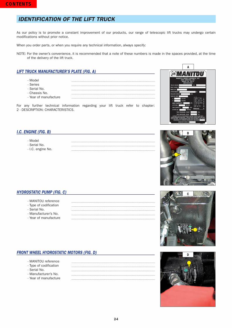
IDENTIFICATION OF THE LIFT TRUCK
As our policy is to promote a constant improvement of our products, our range of telescopic lift trucks may undergo certain modifications without prior notice.
When you order parts, or when you require any technical information, always specify:
NOTE: For the owner’s convenience, it is recommended that a note of these numbers is made in the spaces provided, at the time of the delivery of the lift truck.
LIFT TRUCK MANUFACTURER’S PLATE (FIG. A)
- Model- Series- Serial No.- Chassis No.- Year of manufacture
For any further technical information regarding your lift truck refer to chapter: 2 - DESCRIPTION: CHARACTERISTICS.
I.C. ENGINE (FIG. B)
- Model- Serial No.- I.C. engine No.
HYDROSTATIC PUMP (FIG. C)
- MANITOU reference- Type of codification- Serial No.- Manufacturer’s No.- Year of manufacture
FRONT WHEEL HYDROSTATIC MOTORS (FIG. D)
- MANITOU reference- Type of codification- Serial No.- Manufacturer’s No.- Year of manufacture
A
D
B
C

2-5
FRONT WHEEL REDUCERS (FIG. E)
- Type- Serial No.- Date
REAR WHEEL HYDROSTATIC MOTORS (FIG. F) MH 25-4 T Series 2-E3
- Type of codification- Motor No.- Manufacturer’s No.- Year of manufacture
OVERHEAD GUARD (FIG. G)
- Type- Serial No.
CAB (FIG. H)
- Model- Serial No.- Year of manufacture
MAST (FIG. I)
- Mast identification No.
ATTACHMENT MANUFACTURER’S PLATE (FIG. J)
- Model- Serial No.- Year of manufacture
E
F
G
H
I
J
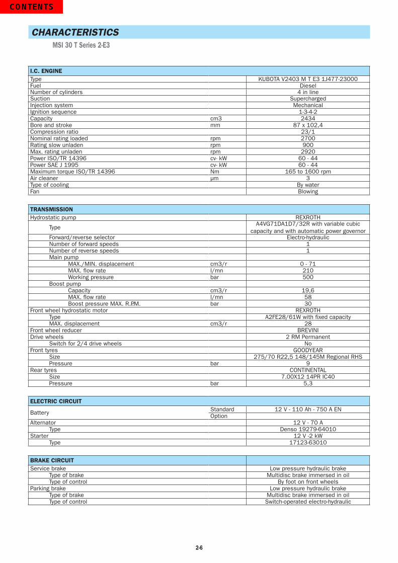
2-6
CHARACTERISTICS MSI 30 T Series 2-E3
I.C. ENGINEType KUBOTA V2403 M T E3 1J477-23000Fuel DieselNumber of cylinders 4 in lineSuction SuperchargedInjection system MechanicalIgnition sequence 1-3-4-2Capacity cm3 2434Bore and stroke mm 87 x 102,4Compression ratio 23/1Nominal rating loaded rpm 2700Rating slow unladen rpm 900Max. rating unladen rpm 2920Power ISO/TR 14396 cv- kW 60 - 44Power SAE J 1995 cv- kW 60 - 44Maximum torque ISO/TR 14396 Nm 165 to 1600 rpmAir cleaner µm 3Type of cooling By waterFan Blowing
TRANSMISSIONHydrostatic pump REXROTH
TypeA4VG71DA1D7/32R with variable cubic
capacity and with automatic power governorForward/reverse selector Electro-hydraulicNumber of forward speeds 1Number of reverse speeds 1Main pump
MAX./MIN. displacement cm3/r 0 - 71MAX. flow rate l/mn 210Working pressure bar 500
Boost pumpCapacity cm3/r 19,6MAX. flow rate l/mn 58Boost pressure MAX. R.P.M. bar 30
Front wheel hydrostatic motor REXROTHType A2FE28/61W with fixed capacityMAX. displacement cm3/r 28
Front wheel reducer BREVINIDrive wheels 2 RM Permanent
Switch for 2/4 drive wheels NoFront tyres GOODYEAR
Size 275/70 R22,5 148/145M Regional RHSPressure bar 9
Rear tyres CONTINENTALSize 7.00X12 14PR IC40Pressure bar 5,3
ELECTRIC CIRCUIT
Battery Standard 12 V - 110 Ah - 750 A ENOption
Alternator 12 V - 70 AType Denso 19279-64010
Starter 12 V -2 kWType 17123-63010
BRAKE CIRCUITService brake Low pressure hydraulic brake
Type of brake Multidisc brake immersed in oilType of control By foot on front wheels
Parking brake Low pressure hydraulic brakeType of brake Multidisc brake immersed in oilType of control Switch-operated electro-hydraulic

2-7
HYDRAULIC MOVEMENTSLifting movements
Unladen lifting m/s 0,5 (1.6 ft/sec)Laden lifting m/s 0,4 (1.3 ft/sec)Unladen lowering m/s 0,4 (1.3 ft/sec)Laden lowering m/s 0,5 (1.6 ft/sec)
HYDRAULIC CIRCUITHydraulic pump CASAPPA
Type Gear pumpCapacity cm3 26 (1.6 cu.in.)Max. rating capacity unladen l/mn 77 (20.3 gal)Flow rate at 1800 rpm l/mn 48 (12.7 gal)
FiltrationReturn µm 10Suction µm 100
Maximum service pressureDouble mast with all-round vision bar 185 (2682 psi)Triple mast with free-acting lift bar 185 (2682 psi)Double mast with free-acting lift bar 185 (2682 psi)Triple mast without free-acting lift barFront/rear tilting circuit bar 185/185 (2682 psi)Attachment circuit bar 185 (2682 psi)Steering circuit bar 125 (1812 psi)
SPECIFICATIONS AND WEIGHTSSpeed of movement for lift truck in standard configuration on flat ground (except particular conditions)
Front unladen km/h 20 (12.4mph) Rear unladen km/h 20 (12.4mph)
Standard mast DVT 3M30Lift height mm 3300 (129.9 in)Free lift height mm 130 (5.1)Overall height (retracted) mm 2300 (90.6 in)Overall height (extended) mm 4131 (162.6 in)
CarriageClass FEM2Awidth mm 1260 (49.6 in)
Weight of forks (each) kg 55 (121.3 lb)Rated load capacity kg 3000 (6614 lb)Rated load capacity with standard mast kg 3000 (6614 lb)Effective load capacity on forks with side-shift carriage kg 3000 (6614 lb)Distance from the centre of gravity of the load to the base of the forks 24 inLift truck weight without forks or mast kg 3959 (8728 lb)Lift truck weight with standard mast
Unladen kg 4704 (10371 lb)At rated load kg 7704 (16984 lb)
Axle weight with standard mast (transport position)Front unladen kg 1899 (4187 lb)Rear unladen kg 2805 (6184 lb)Front rated load kg 6782 (14952 lb)Rear rated load kg 922 (2033 lb)
Drag strain on the coupling hookUnladen (sliding) daN 1300 (2922 ft/lb)At rated load (transmission setting) daN 2400 (5395 ft/lb)
Pull strain with open carrier (according to standard ISO 8313) daN
SOUND AND VIBRATIONLevel of sound pressure in the driver’s cab LpA (according to standard NF EN 12053)
dB 82
Level of sound power ensured in the LwA environment (according to directive 2000/14/EC modified by directive 2005/88/EC)
dB measured/guaranteed
Average weighted acceleration on driver’s body (according to standard NF EN 13059)
m/s2
The average weighted acceleration transmitted to the driver’s hand/arm system (according to standard ISO 5349-2)
m/s2 <2,5
ezuniga
Line
ezuniga
Line
ezuniga
Line
ezuniga
Line
ezuniga
Line
ezuniga
Line
ezuniga
Line
ezuniga
Line
ezuniga
Line

2-8
CHARACTERISTICS MH 25-4 T Series 2-E3
TRANSMISSIONHydrostatic pump REXROTH
TypeA4VG71DA1D7/32R with variable cubic
capacity and with automatic power governorForward/reverse selector Electro-hydraulicNumber of forward speeds 1Number of reverse speeds 1Main pump
MAX./MIN. displacement cm3/r 0 - 71 (0 - 4.3 cu.in.)MAX. flow rate l/mn 210 (55.5 gal/min)Working pressure bar 500 (7250 psi)
Boost pumpCapacity cm3/r 19,6 (1.2 cu.in./r)MAX. flow rate l/mn 58 (15.3 gal/min)Boost pressure MAX. R.P.M. bar 30 (435 psi)
Front wheel hydrostatic motor REXROTHType A2FE28/61W with fixed capacityMAX. displacement cm3/r 28 (1.7 cu.in./r)
Front wheel reducer BREVINIRear wheel hydrostatic motor POCLAIN HYDRAULICS
Type MS02MAX. displacement cm3/r 398 (24.6 cu.in./r)
Drive wheels 4 RM PermanentSwitch for 2/4 drive wheels No
Front tires MICHELINSize 280/80 R20 133A8 XMCLPressure bar 4,4
Rear tires CONTINENTALSize 27.10-12 14PR IC30Pressure bar 7
I.C. ENGINEType KUBOTA V2403 M T E3 1J477-23000Fuel DieselNumber of cylinders 4 in lineSuction SuperchargedInjection system MechanicalIgnition sequence 1-3-4-2Capacity cm3 2434Bore and stroke mm 87 (3.4 in) x 102,4 (4.0 in)Compression ratio 23/1Nominal rating loaded rpm 2700Rating slow unladen rpm 900Max. rating unladen rpm 2920Power ISO/TR 14396 cv- kW 60 - 44Power SAE J 1995 cv- kW 60 - 44Maximum torque ISO/TR 14396 Nm 165 (122 ft/lb) at 1600 rpmAir cleaner µm 3Type of cooling By waterFan Blowing
ELECTRIC CIRCUIT
Battery Standard 12 V - 110 Ah - 750 A ENOption
Alternator 12 V - 70 AType Denso 19279-64010
Starter 12 V -2 kWType 17123-63010
BRAKE CIRCUITService brake Low pressure hydraulic brake
Type of brake Multidisc brake immersed in oilType of control By foot on front wheels
Parking brake Low pressure hydraulic brakeType of brake Multidisc brake immersed in oilType of control Switch-operated electro-hydraulic
ezuniga
Line

2-9
HYDRAULIC MOVEMENTSLifting movements
Unladen lifting m/s 0,6 (2 ft/sec)Laden lifting m/s 0,6 (2 ft/sec)Unladen lowering m/s 0,5 (1.6 ft/sec)Laden lowering m/s 0,6 (2 ft/sec)
HYDRAULIC CIRCUITHydraulic pump CASAPPA
Type Gear pumpCapacity cm3 26 (1.6 cu.in.)Max. rating capacity unladen l/mn 77 (20 gal/min)Flow rate at 1800 rpm l/mn 48 (12.7 gal/min)
FiltrationReturn µm 10Suction µm 100
Maximum service pressureDouble mast with all-round vision bar 170 (2465 psi)Triple mast with free-acting lift bar 180 (2610 psi)Double mast with free-acting lift barTriple mast without free-acting lift bar 180 (2610 psi)Front/rear tilting circuit bar 180/180 (2610 psi)Attachment circuit bar 180 (2610 psi)Steering circuit bar 125 (1813 psi)
SPECIFICATIONS AND WEIGHTSSpeed of movement for lift truck in standard configuration on flat ground (except particular conditions)
Front unladen km/h 14 (8.7 mph)Rear unladen km/h
Standard mast TSLL 3M30Lift height mm 3300 (130 in)Free lift height mm 0Overall height (retracted) mm 1835 (72.2 in)Overall height (extended) mm 4070 (160 in)
CarriageClass FEM2Awidth mm 1260 (49.6 in)
Weight of forks (each) kg 43 (94.8 lb)Rated load capacity kg 2500 (5512 lb)Rated load capacity with standard mast kg 2500 (5512 lb)Effective load capacity on forks with side-shift carriage kg 2400 (5291 lb)Distance from the centre of gravity of the load to the base of the forks 24 in.Lift truck weight without forks or mast kg 3594 (7923 lb)Lift truck weight with standard mast
Unladen kg 4340 (9568 lb)At rated load kg 6840 (15080 lb)
Axle weight with standard mast (transport position)Front unladen kg 1870 (4123 lb)Rear unladen kg 2470 (5445 lb)Front rated load kg 5620 (12390 lb)Rear rated load kg 1220 (2690 lb)
Drag strain on the coupling hookUnladen (sliding) daN 2300 (5170 ft/lb)At rated load (transmission setting) daN 3500 (7868 ft/lb)
Pull strain with open carrier (according to standard ISO 8313) daN
SOUND AND VIBRATIONLevel of sound pressure in the driver’s cab LpA (according to standard NF EN 12053)
dB 82
Level of sound power ensured in the LwA environment (according to directive 2000/14/EC modified by directive 2005/88/EC)
dB measured/guaranteed
Average weighted acceleration on driver’s body (according to standard NF EN 13059)
m/s2
The average weighted acceleration transmitted to the driver’s hand/arm system (according to standard ISO 5349-2)
m/s2 <2,5
ezuniga
Line
ezuniga
Line
ezuniga
Line
ezuniga
Line

2-10
CHARACTERISTICS OF MASTS WITH ROLLERS MSI 30 T Series 2-E3
DOUBLE MAST WITH ALL-ROUND VISION
MAST HL Z Y LL H H1 H2
3m00 119 10° 12° 5.3 85 153 12
3m30 131 10° 12° 5.3 91 165 12
3m50 139 10° 12° 5.3 94 173 12
3m70 147 10° 12° 5.3 101 181 9.4
4m00 159 10° 12° 5.3 108 193 7.8
4m50 179 10° 12° 5.3 118 212 7.8
5m00 198 6° 6° 5.3 128 232 7.8
5m50 218 6° 6° 5.3 138 252 7.8
6m00 238 6° 6° 5.3 149 271 6.2
DOUBLE MAST WITH TOTAL FREE-ACTING LIFT
MAST HL Z Y LL H H1 H2
3m00 120 10° 12° 55 85 150 6.3
3m30 132 10° 12° 61 91 161 6.3
3m50 140 10° 12° 65 94 169 6.3
3m70 147 10° 12° 71 101 177 6.3
4m00 159 10° 12° 79 108 189 6.3
4m50 179 10° 12° 88 118 209 6.3
TRIPLE MAST WITH TOTAL FREE-ACTING LIFT
MAST HL Z Y LL H H1 H2
3m70 147 10° 12° 51 81 177 1.5
4m00 159 10° 12° 55 85 189 1.5
4m30 171 10° 12° 61 91 201 1.5
4m70 187 10° 12° 65 94 217 1.5
5m00 199 6° 6° 71 101 228 1.5
5m50 218 6° 6° 79 108 248 1.5
6m00 238 6° 6° 88 118 268 1.5
6m50 258 6° 6° 98 128 287 1.5
7m00 277 6° 6° 108 138 307 1.5
HL : Lift height in inchesZ : Forward tiltingY : Backward tiltingLL : Free-acting lift in inchesH : Overall height with folded mast in inchesH1 : Overall height with spreaded out mast in inchesH2 : Carriage overshooting in inches
LL
H
HL
H1
H2
Z Y

2-11
CHARACTERISTICS OF MASTS WITH ROLLERS MH 25-4 T Series 2-E3
DOUBLE MAST WITH ALL-ROUND VISION
MAST HL Z Y LL H H1 H2
2m70 107 10° 12° 5.1 79 139 9.7
3m00 119 10° 12° 5.1 84 151 9.7
3m30 131 10° 12° 5.1 90 163 9.7
3m50 139 10° 12° 5.1 94 171 9.7
3m70 147 10° 12° 5.1 101 178 7.3
4m00 159 10° 12° 5.1 108 190 5.7
4m50 178 10° 12° 5.1 118 210 5.7
DOUBLE MAST WITH TOTAL FREE-ACTING LIFT
MAST HL Z Y LL H H1 H2
3m00 120 10° 12° 55 84 149 6.0
3m30 131 10° 12° 60.6 90.4 161 6.0
3m50 139 10° 12° 64.5 94.3 169 6.0
3m70 147 10° 12° 70.8 101 177 6.0
4m00 159 10° 12° 78.3 108 188 6.0
4m50 179 10° 12° 88.1 118 209 6.0
TRIPLE MAST WITH TOTAL FREE-ACTING LIFT
MAST HL Z Y LL H H1 H2
3m70 147 10° 12° 47.9 76.6 176 2.1
4m00 159 10° 12° 51.8 80.5 188 2.1
4m30 171 10° 12° 55.7 84.4 200 2.1
4m70 187 10° 12° 61.7 90.4 215 2.1
TRIPLE MAST WITHOUT FREE-ACTING LIFT
MAST HL Z Y LL H H1 H2
3m30 131 10° 12° 0 72.2 160 1.4
HL : Lift height in inchesZ : Forward tiltingY : Backward tiltingLL : Free-acting lift in inchesH : Overall height with folded mast in inchesH1 : Overall height with spreaded out mast in inchesH2 : Carriage overshooting in inches
LL
H
HL
H1
H2
Z Y
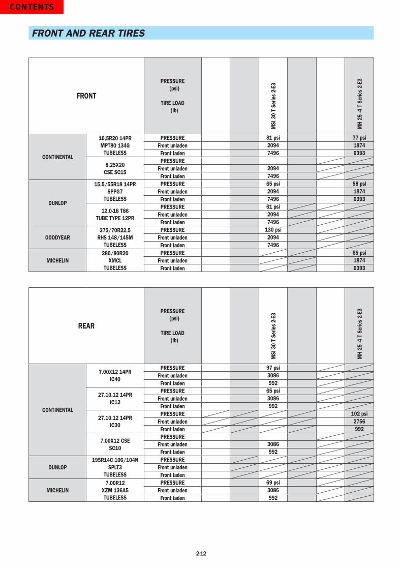
2-12
FRONT AND REAR TIRES
FRONT
PRESSURE(psi)
TIRE LOAD(lb)
MSI
30
T Se
ries
2-E3
MH
25 -4
T S
erie
s 2-
E3
CONTINENTAL
10,5R20 14PRMPT80 134G
TUBELESS
PRESSURE 81 psi 77 psiFront unladen 2094 1874Front laden 7496 6393
8,25X20CSE SC15
PRESSUREFront unladen 2094Front laden 7496
DUNLOP
15,5/55R18 14PRSPPG7
TUBELESS
PRESSURE 65 psi 58 psiFront unladen 2094 1874Front laden 7496 6393
12,0-18 T86TUBE TYPE 12PR
PRESSURE 61 psiFront unladen 2094Front laden 7496
GOODYEAR275/70R22,5
RHS 148/145MTUBELESS
PRESSURE 130 psiFront unladen 2094Front laden 7496
MICHELIN280/80R20
XMCLTUBELESS
PRESSURE 65 psiFront unladen 1874Front laden 6393
REAR
PRESSURE(psi)
TIRE LOAD(lb)
MSI
30
T Se
ries
2-E3
MH
25 -4
T S
erie
s 2-
E3
CONTINENTAL
7.00X12 14PRIC40
PRESSURE 97 psiFront unladen 3086Front laden 992
27.10.12 14PRIC12
PRESSURE 65 psiFront unladen 3086Front laden 992
27.10.12 14PRIC30
PRESSURE 102 psiFront unladen 2756Front laden 992
7.00X12 CSESC10
PRESSUREFront unladen 3086Front laden 992
DUNLOP195R14C 106/104N
SPLT3TUBELESS
PRESSUREFront unladenFront laden
MICHELIN7.00R12
XZM 136A5TUBELESS
PRESSURE 69 psiFront unladen 3086Front laden 992
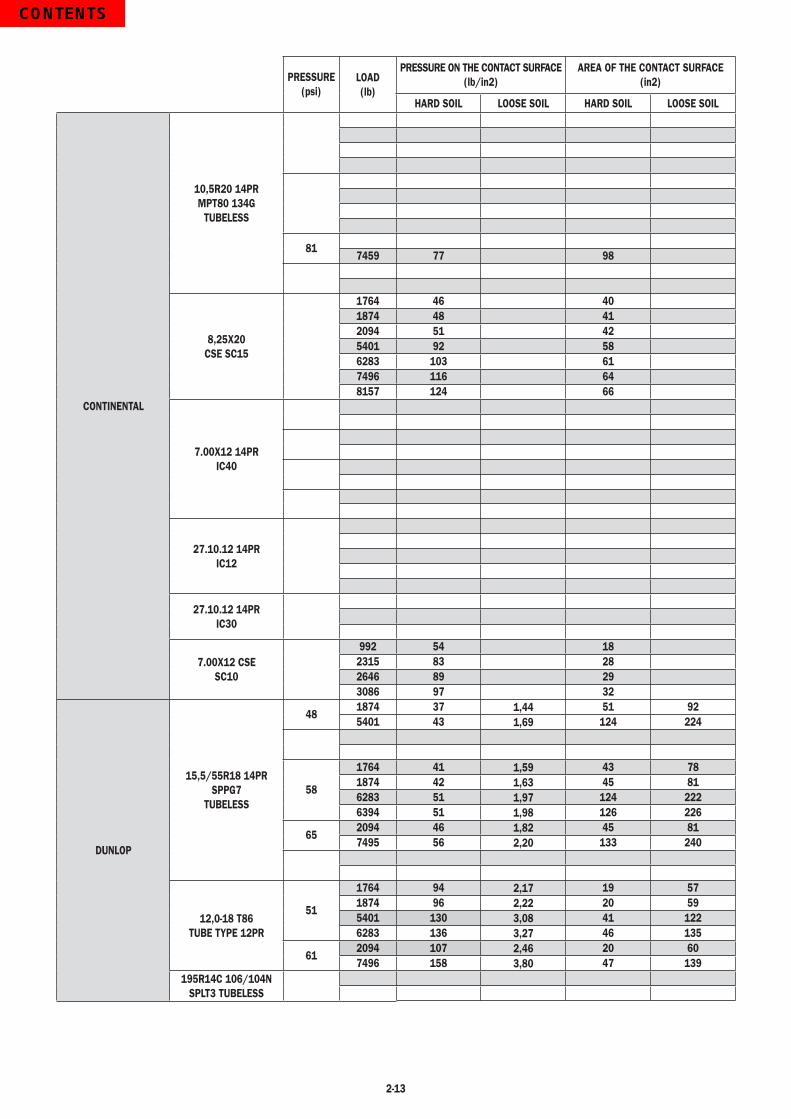
2-13
PRESSURE (psi)
LOAD(lb)
PRESSURE ON THE CONTACT SURFACE (lb/in2)
AREA OF THE CONTACT SURFACE (in2)
HARD SOIL LOOSE SOIL HARD SOIL LOOSE SOIL
CONTINENTAL
10,5R20 14PRMPT80 134G
TUBELESS
817459 77 98
8,25X20CSE SC15
1764 46 401874 48 412094 51 425401 92 586283 103 617496 116 648157 124 66
7.00X12 14PRIC40
27.10.12 14PRIC12
27.10.12 14PRIC30
7.00X12 CSESC10
992 54 182315 83 282646 89 293086 97 32
DUNLOP
15,5/55R18 14PRSPPG7
TUBELESS
481874 37 1,44 51 925401 43 1,69 124 224
58
1764 41 1,59 43 781874 42 1,63 45 816283 51 1,97 124 2226394 51 1,98 126 226
652094 46 1,82 45 817495 56 2,20 133 240
12,0-18 T86TUBE TYPE 12PR
51
1764 94 2,17 19 571874 96 2,22 20 595401 130 3,08 41 1226283 136 3,27 46 135
612094 107 2,46 20 607496 158 3,80 47 139
195R14C 106/104NSPLT3 TUBELESS

2-14
PRESSURE (psi)
LOAD(lb)
PRESSURE ON THE CONTACT SURFACE (lb/in2)
AREA OF THE CONTACT SURFACE (in2)
HARD SOIL LOOSE SOIL HARD SOIL LOOSE SOIL
GOODYEAR275/70R22,5
RHS 148/145MTUBELESS
131
MICHELIN
280/80R20XMCL
TUBELESS
59
64
65
7.00R12XZM 136A5TUBELESS
51992 46 222315 46 50
58
69992 50 203086 67 46
101

2-15

2-16
DIMENSIONS AND LOAD CHART MSI 30 T Series 2-E3
G - G1 - G2 - G3 = UnladenG* - G1* - G2* = Rated loadU = MSI 30 T Series 2-E3
DD : mm
mm
kg
mm
1
2
1
2
CAPACITE NOMINALERATED CAPACITYNENNKAPAZITÄTCAPACIDAD NOMINALCAPACITÀ NOMINALE
CAPACITES EFFECTIVESACTUAL CAPACITIESEFFEKTIVE KAPAZITÄTCAPACIDAD EFECTIVACAPACITÀ EFFETTIVA
CAPACITES EFFECTIVESACTUAL CAPACITIESEFFEKTIVE KAPAZITÄTCAPACIDAD EFECTIVACAPACITÀ EFFETTIVA
n°:
1 - Jusqu'à hauteur de levéeUp to height ofBis zur hubhöheHasta altura de elevaciónSino ad altezza di sollevamento
2 - Pour hauteur maximale deFor maximum height ofFür maximale HöhePara altura máxima dePer altezza massima di
MAT VERTICALVERTICAL MASTVERTIKALER MASTMASTIL VERTICALRAMPA VERTICALE
EQUIPEMENTATTACHMENTZUBEHÖREQUIPOATTREZZATURA
Q : kg
3300
3000
-
- - -3000 2750 1960
500 600 1100
- - -3000 2750 1960
60E-SS-B621100E-SS-B551100E-SS-B687
-
218157
SUIVANT NORME EN 1726-1 (ISO 1074)
A mm (inch) 1100 (43.3)B mm (inch) 1800 (70.9)C mm (inch) 630 (24.8)D mm (inch) 2980 (117)E mm (inch) 4080 (161)F mm (inch) 1046 (41.2)F1 mm (inch) 1102 (43.4)G mm (inch) 270 (10.6)G* mm (inch) 240 (9.4)G1 mm (inch) 260 (10.2)G1* mm (inch) 260 (10.2)G2 mm (inch) 215 (8.5)G2* mm (inch) 230 (9.1)G3 mm (inch) 270 (10.6)H mm (inch) 2300 (90.6)H1 mm (inch) 4193 (165)I mm (inch) 550 (21.7)J mm (inch) 1025 (40.4)K mm (inch) 1260 (49.6)L mm (inch) 45 (1.8)N mm (inch) 1450 (57.1)O mm (inch) 100 (3.9)P1 (°) 49.5P2 (°) 40.5P3 (°) 40R mm (inch) 2310 (90.9)S mm (inch) 4560 (180)T mm (inch) 2485 (97.8)U mm (inch) 2105 (82.9)
V mm (inch) 2635 (104)V1 mm (inch) 150 (5.9)W mm (inch) 1323 (52.1)Y (°) 12 (0.5)Z (°) 10 (0.4)
RATED CAPACITY
ACTUAL CAPACITIES(according to standard EN 1726-1)
1 - Up to height of
2 - For maximum height of
VERTICAL MAST
ATTACHMENT
ACTUAL CAPACITIES

2-17
DIMENSIONS AND LOAD CHART MH 25-4 T Series 2-E3
G - G1 - G2 - G3 = UnladenG* - G1* - G2* = Rated load
DD : mm
mm
kg
mm
1
2
1
2
CAPACITE NOMINALERATED CAPACITYNENNKAPAZITÄTCAPACIDAD NOMINALCAPACITÀ NOMINALE
CAPACITES EFFECTIVESACTUAL CAPACITIESEFFEKTIVE KAPAZITÄTCAPACIDAD EFECTIVACAPACITÀ EFFETTIVA
CAPACITES EFFECTIVESACTUAL CAPACITIESEFFEKTIVE KAPAZITÄTCAPACIDAD EFECTIVACAPACITÀ EFFETTIVA
n°:
1 - Jusqu'à hauteur de levée Up to height of Bis zur hubhöhe Hasta altura de elevación Sino ad altezza di sollevamento
2 - Pour hauteur maximale de For maximum height of Für maximale Höhe Para altura máxima de Per altezza massima di
MAT VERTICALVERTICAL MASTVERTIKALER MASTMASTIL VERTICALRAMPA VERTICALE
EQUIPEMENTATTACHMENTZUBEHÖREQUIPOATTREZZATURA
Q : kg
3300
2500
-
- - -2500 2290 1630
500 600 1100
- - -2500 2290 1630
55F-SS-A93155F-SS-A93255F-SS-A933
-
218136
SUIVANT NORME EN 1726-1 (ISO 1074)
DD : mm
mm
kg
mm
1
2
1
2
CAPACITE NOMINALERATED CAPACITYNENNKAPAZITÄTCAPACIDAD NOMINALCAPACITÀ NOMINALE
CAPACITES EFFECTIVESACTUAL CAPACITIESEFFEKTIVE KAPAZITÄTCAPACIDAD EFECTIVACAPACITÀ EFFETTIVA
CAPACITES EFFECTIVESACTUAL CAPACITIESEFFEKTIVE KAPAZITÄTCAPACIDAD EFECTIVACAPACITÀ EFFETTIVA
n°:
1 - Jusqu'à hauteur de levée Up to height of Bis zur hubhöhe Hasta altura de elevación Sino ad altezza di sollevamento
2 - Pour hauteur maximale de For maximum height of Für maximale Höhe Para altura máxima de Per altezza massima di
MAT VERTICALVERTICAL MASTVERTIKALER MASTMASTIL VERTICALRAMPA VERTICALE
EQUIPEMENTATTACHMENTZUBEHÖREQUIPOATTREZZATURA
Q : kg
3300
2500
-
- - -2500 2290 1630
500 600 1100
- - -2400 2200 1560
55F-SS-A93155F-SS-A93255F-SS-A933
-
242866
SUIVANT NORME EN 1726-1 (ANNEXE H)
RATED CAPACITY
ACTUAL CAPACITIES(according to standard EN 1726-1)
1 - Up to height of
2 - For maximum height of
VERTICAL MAST
ATTACHMENT
ACTUAL CAPACITIES
ROUGH TERRAIN (1) INDUSTRIAL FLOOR (2)
(1) The «rough terrain» load chart (according to EN 1726-1 appendix H) for use on natural, undeveloped, unleveled ground or on construction sites.
(2) The «industrial floor» load chart (according to EN 1726-1 ISO 1074) for use on firm, smooth, flat and prepared surfaces.
A mm (inch) 1100 (43.3)B mm (inch) 1800 (70.9)C mm (inch) 625 (24.6)D mm (inch) 2945 (116)E mm (inch) 4045 (159)F mm (inch) 1160 (45.7)F1 mm (inch) 1164 (45.9)G mm (inch) 265 (10.4)G* mm (inch) 235 (9.2)G1 mm (inch) 260 (10.2)G1* mm (inch) 260 (10.2)G2 mm (inch) 215 (8.5)G2* mm (inch) 230 (9.1)G3 mm (inch) 270 (10.6)H mm (inch) 1835 (72.2)H1 mm (inch) 4070 (160)I mm (inch) 520 (20.5)J mm (inch) 1025 (40.4)K mm (inch) 1260 (49.6)L mm (inch) 40 (1.6)N mm (inch) 1450 (57.0)O mm (inch) 100 (3.9)P1 (°) 49.5P2 (°) 40.5P3 (°) 44R mm (inch) 3045 (120)S mm (inch) 5090 (200)T mm (inch) 2500 (98.4)U mm (inch) 1990 (78.3)V mm (inch) 3265 (129)V1 mm (inch) 1080 (42.5)W mm (inch) 1450 (57.1)Y (°) 12Z (°) 10
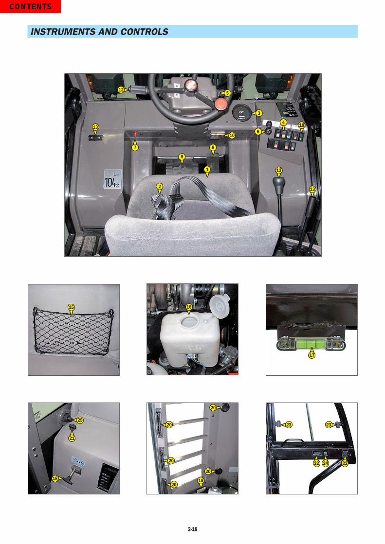
2-18
INSTRUMENTS AND CONTROLS
15 16
17
25
21
18
22
2323
24 22
512
7
3
6
4 18
13
13
8
9
1
2
13
10
20
20
20
20
20
19
2-19
DESCRIPTION
1 - DRIVER’S SEAT2 - SAFETY BELT3 - CONTROL AND SIGNAL LIGHTS PANEL4 - SWITCHES5 - HORN SWITCH6 - IGNITION SWITCH7 - BATTERY CUT-OFF8 - ACCELERATOR PEDAL9 - SERVICE BRAKE PEDAL AND TRANSMISSION CUT-OFF10 - FUSES AND RELAYS IN THE CAB11 - FUSES AND RELAYS UNDER THE CAB (NOT ILLUSTRATED)12 - FORWARD/NEUTRAL/REVERSE GEAR SELECTION13 - HYDRAULIC CONTROLS14 - DOCUMENT CLIP15 - DOCUMENT HOLDER NET16 - WINDSCREEN WASHER TANK17 - LEVEL INDICATOR18 - OVERHEAD GUARD LIFTING18 - CAB LIFTING (OPTION)19 - ROOF LIGHT (OPTION)20 - HEATING VENTS (OPTION)21 - HEATER CONTROL (OPTION)22 - DOOR LOCKS (OPTION)23 - LEFT SIDE WINDSCREEN OPENING HANDLES (OPTION)24 - LOCKING HANDLE FOR UPPER HALF DOOR (OPTION)25 - RELEASING BUTTON FOR UPPER HALF DOOR (OPTION)26 - STEERING WHEEL TILTING HANDLE (OPTION) (NOT ILLUSTRATED)
NOTE: All the terms such as: RIGHT, LEFT, FRONT, REAR are meant for an observer seated on driver’s seat facing foward.

2-20
1 - DRIVER’S SEAT
DESIGNED FOR MAXIMUM COMFORT, THIS SEAT CAN BE ADJUSTED AS FOLLOWS.
LONGITUDINAL ADJUSTMENT- Pull the locking lever 1 upwards.- Slide the seat to the required position.- Release the lever and ensure it returns to the lock position.
SEAT SUSPENSION ADJUSTMENT- Pull and lift up the locking lever 2 so as to place it into one of these five positions.
Position A : Light-weight driver (110 lb).Position B : Intermediate.Position C : Middle-weight driver.Position D : Intermediate.Position E : Heavy-weight driver (265 lb).
ANGLE ADJUSTMENT OF THE BACK-REST- Pull the locking lever 3 backwards.- Tilt the back-rest into one of the three possible positions.- Release the locking lever and ensure it returns to the lock position.
ANGLE ADJUSTMENT OF THE WHOLE SEAT- Lift up the locking lever 4.- Tilt the seat forwards or backwards.- Release the lever and ensure it returns to the lock position.
2 - SAFETY BELT
- Sit correctly on the seat.- Check that the seat belt is not twisted.- Place the seat belt at hip level.- Attach the seat belt and check that it locks.- Adjust the seat belt to your body shape without squeezing your hip and without over-slack.
Do not operate the lift truck with a defective seat belt (fixing, locking, cuts, tears, etc.). Repair or replace the seat belt immediately.WARNING
A
E
B
C
D
2
1
4
3

2-21
3 - CONTROL AND SIGNAL LIGHTS PANEL
CONTROL INSTRUMENTS
A - HOURMETER
B - FUEL LEVELRed zone B1 indicates that you are using the reserve supply and that time of use is limited.
SIGNAL LIGHTS
When activating the electrical system of the lift truck, all the red lamps and the panel’s buzzer must light to indicate their good working order. If one of the red lamps or the buzzer does not function, carry out the necessary repairs.
RED LAMP - HYDRAULIC RETURN FILTER CLOGGEDThe lamp and buzzer come on when the hydraulic return oil filter cartridge is clogged up. Stop the lift truck and carry out the necessary repairs (see cleaning and replacement requirements in chapter: 3 - MAINTENANCE: FILTERS CARTRIDGES AND BELTS).NOTE: This lamp comes on by cold weather or when starting the fork lift truck, it goes off when the hydraulic oil reaches the
working temperature.
NOT USED
RED I.C. ENGINE WATER TEMPERATURE LAMPIf the lamp and the buzzer come on when the lift truck is running, stop the I.C. engine immediately and investigate the cooling circuit for the cause of the malfunction.
RED PARKING BRAKE LAMPThis lamp comes on when the parking brake is applied.
RED BATTERY CHARGE WARNING INDICATOR LIGHTIf the red lamps and the buzzer come on, when the lift truck is running, stop the I.C. engine immediately and check the electrical circuit as well as the alternator belt.
RED I.C. ENGINE OIL PRESSURE LAMPIf the lamp and the buzzer come on when the lift truck is running, stop the I.C. engine immediately and look for the cause (see oil level in I.C. engine crankcase).
K - RED AIR FILTER CLOGGING INDICATOR LAMPThe lamp and the buzzer come on when the air filter cartridge is clogged up. Stop the lift truck and carry out the necessary repairs (see cleaning and replacement requirements in chapter: 3 - MAINTENANCE: FILTERS CARTRIDGES AND BELTS).
BLUE MAIN BEAM LAMP (OPTION)
GREEN INDICATOR LAMP (OPTION)
0000000 h
B
A
B1
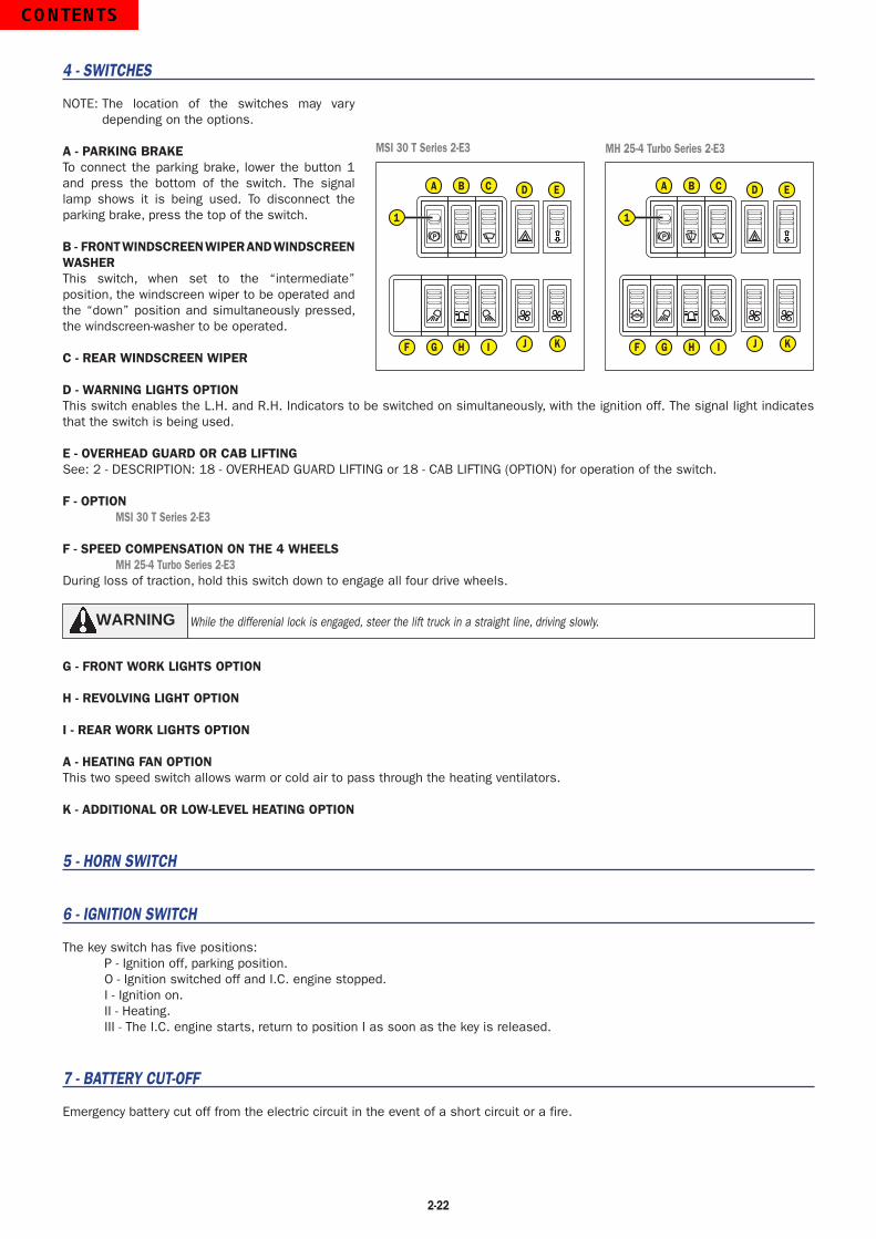
2-22
4 - SWITCHES
NOTE: The location of the switches may vary depending on the options.
A - PARKING BRAKETo connect the parking brake, lower the button 1 and press the bottom of the switch. The signal lamp shows it is being used. To disconnect the parking brake, press the top of the switch.
B - FRONT WINDSCREEN WIPER AND WINDSCREEN WASHERThis switch, when set to the “intermediate” position, the windscreen wiper to be operated and the “down” position and simultaneously pressed, the windscreen-washer to be operated.
C - REAR WINDSCREEN WIPER
D - WARNING LIGHTS OPTIONThis switch enables the L.H. and R.H. Indicators to be switched on simultaneously, with the ignition off. The signal light indicates that the switch is being used.
E - OVERHEAD GUARD OR CAB LIFTINGSee: 2 - DESCRIPTION: 18 - OVERHEAD GUARD LIFTING or 18 - CAB LIFTING (OPTION) for operation of the switch.
F - OPTION MSI 30 T Series 2-E3
F - SPEED COMPENSATION ON THE 4 WHEELS MH 25-4 Turbo Series 2-E3During loss of traction, hold this switch down to engage all four drive wheels.
While the differenial lock is engaged, steer the lift truck in a straight line, driving slowly.WARNING
G - FRONT WORK LIGHTS OPTION
H - REVOLVING LIGHT OPTION
I - REAR WORK LIGHTS OPTION
A - HEATING FAN OPTIONThis two speed switch allows warm or cold air to pass through the heating ventilators.
K - ADDITIONAL OR LOW-LEVEL HEATING OPTION
5 - HORN SWITCH
6 - IGNITION SWITCH
The key switch has five positions:P - Ignition off, parking position.O - Ignition switched off and I.C. engine stopped.I - Ignition on.II - Heating.III - The I.C. engine starts, return to position I as soon as the key is released.
7 - BATTERY CUT-OFF
Emergency battery cut off from the electric circuit in the event of a short circuit or a fire.
MSI 30 T Series 2-E3 MH 25-4 Turbo Series 2-E3
P
A B C D E
F G H I J K
1P
A B C D E
F G H I J K
1

2-23
8 - ACCELERATOR PEDAL
9 - SERVICE BRAKE PEDAL AND TRANSMISSION CUT-OFF
This pedal operates in two steps:- First, the pedal acts upon a hydraulic valve which progressively cuts off the hydrostatic transmission so as to carry out a slow approach with all the I.C. engine output.
- Then, the pedal acts upon a hydraulic valve which progressively makes the pressure in the brakes drop so as to immobilize the lift truck.
10 - FUSES AND RELAYS IN THE CAB
- Remove the casing to access fuses F1 to F24.
NOTE: Always replace a faulty fuse with another of equivalent rating. Never use a fuse that has been repaired.
F1 - OPTION Light switch power supply, horn and indicators (15A). F2 - OPTION Hazard warning lights power supply (10A). F3 - Rear windscreen wiper (7.5A). F4 - Stop I.C. engine electrovalve (5A). F5 - OPTION 1 Front work light (7.5 A). - OPTION 2 Front work lights (15A). F6 - OPTION Heating (15A). F7 - Control panel (5A). F8 - Front windscreen wiper and windscreen-washer (10A). F9 - OPTION Indicator power supply (10A). F10 - Reversing gear (10A). - OPTION Reversing light (10A). - OPTION Audible reversing alarm (10A). F11 - Parking brake (10A). - Sound alarm (10A). - OPTION stop switch (10A). F12 - OPTION Revolving light (7.5A). F13 - OPTION Right-hand sidelights (5A). F14 - OPTION Left-hand sidelights (5A). F15 - OPTION Right-hand indicators (7.5A). F16 - OPTION Left-hand indicators (7.5A). F17 - OPTION Dipped headlights (10A). F18 - OPTION Main headlights (10A). F19 - OPTION Roof light (3A). F20 - OPTION (+) permanent (3A). F21 - OPTION 1 Rear work light (7.5A). - OPTION 2 Rear work lights (15A). F22 - Differential lock (5A). MH 25-4 Turbo Series 2-E3 F23 - Starter (20A). F24 - Overhead guard or cab lifting (5A).
- Remove plate 1 to access relays K1 to K6 and B2. K1 - Safety system starting switch relay. K2 - OPTION Flashing unit. K3 - Reverse gear relay. K5 - Transmission cut-off relay. K6 - Forward gear relay. B2 - Buzzer.
11 - FUSES AND RELAYS UNDER THE CAB
Remove cover 1 in order to gain access to the fuses.
NOTE: Always replace a faulty fuse with another of equivalent rating. Never use a fuse that has been repaired.
F25 - Preheating I.C. engine (50A). F26 - Alternator (70A). F27 - Lift truck electrical equipment (70A). F28 - Overhead guard or cab lifting (50A).
K7 - Preheating relay. - OPTION diesel decongealant relay. - OPTION diesel decongealant fuse (15A).
7 8 9 10 11 12
1 2 3 4 5 6
13
22 2423
19 2120
14 15 16 17 18
1
K6K3
K5
K2 B2 K1
F27
F26
F28
F25
K7
1
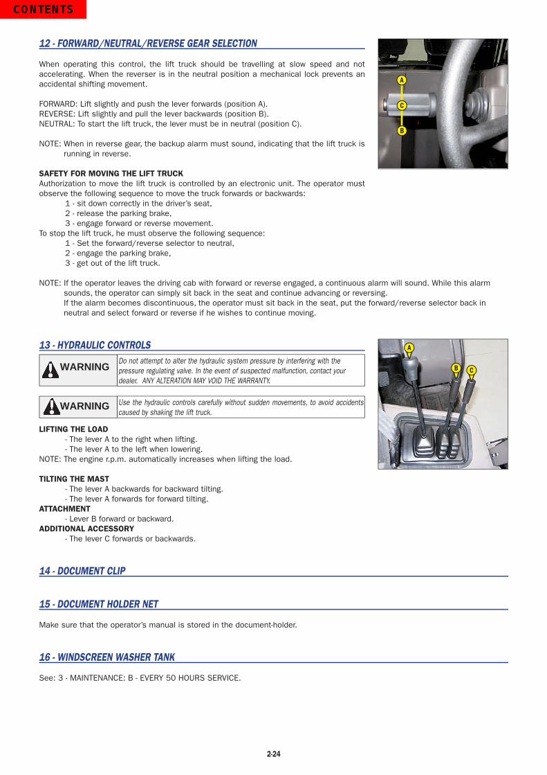
2-24
12 - FORWARD/NEUTRAL/REVERSE GEAR SELECTION
When operating this control, the lift truck should be travelling at slow speed and not accelerating. When the reverser is in the neutral position a mechanical lock prevents an accidental shifting movement.
FORWARD: Lift slightly and push the lever forwards (position A).REVERSE: Lift slightly and pull the lever backwards (position B).NEUTRAL: To start the lift truck, the lever must be in neutral (position C).
NOTE: When in reverse gear, the backup alarm must sound, indicating that the lift truck is running in reverse.
SAFETY FOR MOVING THE LIFT TRUCKAuthorization to move the lift truck is controlled by an electronic unit. The operator must observe the following sequence to move the truck forwards or backwards:
1 - sit down correctly in the driver’s seat,2 - release the parking brake,3 - engage forward or reverse movement.
To stop the lift truck, he must observe the following sequence:1 - Set the forward/reverse selector to neutral,2 - engage the parking brake,3 - get out of the lift truck.
NOTE: If the operator leaves the driving cab with forward or reverse engaged, a continuous alarm will sound. While this alarm sounds, the operator can simply sit back in the seat and continue advancing or reversing.If the alarm becomes discontinuous, the operator must sit back in the seat, put the forward/reverse selector back in neutral and select forward or reverse if he wishes to continue moving.
13 - HYDRAULIC CONTROLSDo not attempt to alter the hydraulic system pressure by interfering with the pressure regulating valve. In the event of suspected malfunction, contact your dealer. ANY ALTERATION MAY VOID THE WARRANTY.
WARNING
Use the hydraulic controls carefully without sudden movements, to avoid accidents caused by shaking the lift truck.
WARNING
LIFTING THE LOAD- The lever A to the right when lifting.- The lever A to the left when lowering.
NOTE: The engine r.p.m. automatically increases when lifting the load.
TILTING THE MAST- The lever A backwards for backward tilting.- The lever A forwards for forward tilting.
ATTACHMENT- Lever B forward or backward.
ADDITIONAL ACCESSORY- The lever C forwards or backwards.
14 - DOCUMENT CLIP
15 - DOCUMENT HOLDER NET
Make sure that the operator’s manual is stored in the document-holder.
16 - WINDSCREEN WASHER TANK
See: 3 - MAINTENANCE: B - EVERY 50 HOURS SERVICE.
A
C
B
A
B C

2-25
17 - LEVEL INDICATOR
Enables the operator to check that the lift truck is in the horizontal position.
18 - OVERHEAD GUARD LIFTING (WITHOUT DOORS)
CAUTION
Make sure that the mast is tilted fully forward and the engine is stopped before lifting the overhead guard.
CAUTION
Check for any objects left in the operator’s area which may interrupt the lifting operation.
UNLOCKING THE OVERHEAD GUARD- With the engine stopped, turn the ignition on in the lift truck.- Unlock the overhead guard by means of the lever 1 (fig. A) in position A.
LIFTING THE OVERHEAD GUARD- Press the top of the switch 2 (fig. B) until complete lifting of the overhead guard.- Put the lever 1 back into position B (fig. C).- Place the safety prop 3 onto its stop 4 (fig. D).
LOWERING THE OVERHEAD GUARD- Fold the safety prop back into its clip 5 (fig. E).- Lower the overhead guard into its initial position by pressing the bottom of the switch 2 (fig. B).
- Ensure that the overhead guard is locked.
CAUTION
Check for clearance and obstacles while lowering the overhead guard.
P
B2
D
3
4
A
1
BA
E
5
C
1
BA
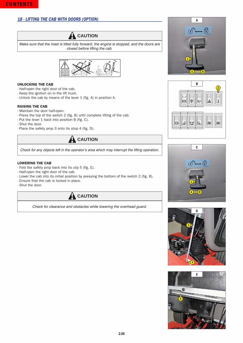
2-26
18 - LIFTING THE CAB WITH DOORS (OPTION)
CAUTION
Make sure that the mast is tilted fully forward, the engine is stopped, and the doors are closed before lifting the cab.
N°234878
UNLOCKING THE CAB- Half-open the right door of the cab.- Keep the ignition on in the lift truck.- Unlock the cab by means of the lever 1 (fig. A) in position A.
RAISING THE CAB- Maintain the door half-open.- Press the top of the switch 2 (fig. B) until complete lifting of the cab.- Put the lever 1 back into position B (fig. C).- Shut the door.- Place the safety prop 3 onto its stop 4 (fig. D).
CAUTION
Check for any objects left in the operator’s area which may interrupt the lifting operation.
LOWERING THE CAB- Fold the safety prop back into its clip 5 (fig. E).- Half-open the right door of the cab.- Lower the cab into its initial position by pressing the bottom of the switch 2 (fig. B).- Ensure that the cab is locked in place.- Shut the door.
CAUTION
Check for clearance and obstacles while lowering the overhead guard.
P
B2
D
3
4
A
1
BA
E
5
C
1
BA
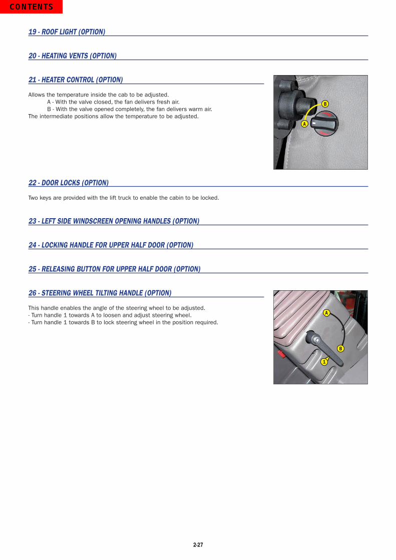
2-27
19 - ROOF LIGHT (OPTION)
20 - HEATING VENTS (OPTION)
21 - HEATER CONTROL (OPTION)
Allows the temperature inside the cab to be adjusted.A - With the valve closed, the fan delivers fresh air.B - With the valve opened completely, the fan delivers warm air.
The intermediate positions allow the temperature to be adjusted.
22 - DOOR LOCKS (OPTION)
Two keys are provided with the lift truck to enable the cabin to be locked.
23 - LEFT SIDE WINDSCREEN OPENING HANDLES (OPTION)
24 - LOCKING HANDLE FOR UPPER HALF DOOR (OPTION)
25 - RELEASING BUTTON FOR UPPER HALF DOOR (OPTION)
26 - STEERING WHEEL TILTING HANDLE (OPTION)
This handle enables the angle of the steering wheel to be adjusted.- Turn handle 1 towards A to loosen and adjust steering wheel.- Turn handle 1 towards B to lock steering wheel in the position required.
A
B
B
A
1

2-28
TOWING PIN AND HOOK
Located at the rear of the lift truck, this device is used to attach a trailer. Its capacity is limited for each lift truck by the authorized gross vehicle weight, tractive effort and maximum vertical force on the coupling point. This information is given on the manufacturer’s plate fixed to each lift truck (see : 2 - DESCRIPTION : IDENTIFICATION OF THE LIFT TRUCK).
- To use a trailer, see current regulations in your country (maximum running speed, braking, maximum weight of trailer, etc.).- Verify the trailer’s condition before using it (tire condition and pressures, electrical connection, hydraulic hose, braking system…).
Do not tow a trailer or accessory which is not in proper working order. Using a trailer in poor condition may effect the lift truck’s steering and braking, and safety.
WARNING
If a third party helps in coupling or uncoupling the trailer, they must be continually visible to the driver until the lift truck is parked and the I.C. engine is turned off.
WARNING
A - TOWING PIN
COUPLING AND UNCOUPLING THE TRAILER- To couple the trailer, position the lift truck as close as possible to the trailer ring.- Engage the parkbrake and switch off the I.C. engine.- Remove the clip 1, lift the trailer pin 2 and place or remove the trailer ring.
Risk of crushed fingers or hands! Keep hands and fingers clear while coupling the trailer! The safety clip 1 must be installed after coupling. Before uncoupling, make sure the trailer is blocked in place and independently supported.
WARNING
2
1

2-29

2-30
DESCRIPTION AND USE OF ELECTRIC AND HYDRAULIC OPTIONS
1 - REVOLVING LIGHT
The revolving light is removable to make it possible, for example, to reduce the height of the lift truck or to avoid theft.- Loosen nut 1 and remove the revolving light.- Protect mounting 2 with cap 3.
2 - LIGHT SWITCH, HORN AND INDICATOR SWITCH
The switch controls the visual and sound alarms.A - All lights are off, the direction indicators do not flash.B - The right hand direction indicators flash.C - The left hand direction indicators flash.D - The sidelights and the rear lights are on.E - The dipped headlights and the rear lights are on.F - The main beam headlights and the rear lights are on.G - Headlight signal.
Pressing the switch sounds the horn.NOTE : The positions D - E - F - G can be carried out without the ignition being on.
3 - FRONT LIGHTS
A - Left front indicator.B - Left front sidelight.C - Left front dipped headlight and main beam.D - Right front sidelight.E - Right front dipped headlight and main beam.F - Right front indicator.
4 - REAR LIGHTS (OPEN CAB MODEL)
A - Left rear indicator.B - Left tail light.C - Left rear stoplight.D - Right rear stoplight.E - Right tail light.F - Right rear indicator.
2
3
1
BDF A
E C
A C
B
D F
E
DG F
A C
BE

2-31
5 - REAR LIGHTS (ENCLOSED CAB MODEL)
A - Left rear indicator.B - Left tail light.C - Left rear stoplight.D - Right rear stoplight.E - Right tail light.F - Right rear indicator.
6 - REAR REVERSE LIGHT
7 - REVERSE BUZZER ALARM
8 - EMERGENCY STOP BUTTON
- I n the event of emergency, it lets you stop the I.C. Engine and stop all hydraulic movements.
- Turn the button to disable it before restarting the lift truck.
CAUTION
Be ready for hydraulic movements suddenly stopping when you press this button.
9 - ADAPTATION CONTROLS LIFTING/TILTING REVERSED
LIFTING OF THE LOAD- The lever A backwards when lifting.- The lever A forwards when lowering.
NOTE : The engine r.p.m. automatically increases when lifting the load.
TILT OF THE MAST- The lever A to the left for backward tilting.- The lever A to the right for forward tilting.
E
FD
B
CA
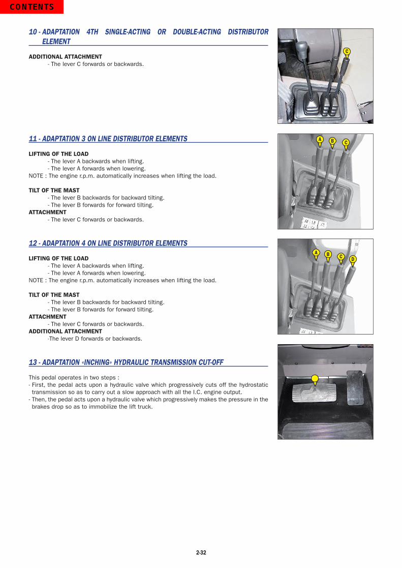
2-32
10 - ADAPTATION 4TH SINGLE-ACTING OR DOUBLE-ACTING DISTRIBUTOR ELEMENT
ADDITIONAL ATTACHMENT- The lever C forwards or backwards.
11 - ADAPTATION 3 ON LINE DISTRIBUTOR ELEMENTS
LIFTING OF THE LOAD- The lever A backwards when lifting.- The lever A forwards when lowering.
NOTE : The engine r.p.m. automatically increases when lifting the load.
TILT OF THE MAST- The lever B backwards for backward tilting.- The lever B forwards for forward tilting.
ATTACHMENT- The lever C forwards or backwards.
12 - ADAPTATION 4 ON LINE DISTRIBUTOR ELEMENTS
LIFTING OF THE LOAD- The lever A backwards when lifting.- The lever A forwards when lowering.
NOTE : The engine r.p.m. automatically increases when lifting the load.
TILT OF THE MAST- The lever B backwards for backward tilting.- The lever B forwards for forward tilting.
ATTACHMENT- The lever C forwards or backwards.
ADDITIONAL ATTACHMENT-The lever D forwards or backwards.
13 - ADAPTATION «INCHING» HYDRAULIC TRANSMISSION CUT-OFF
This pedal operates in two steps :- First, the pedal acts upon a hydraulic valve which progressively cuts off the hydrostatic transmission so as to carry out a slow approach with all the I.C. engine output.
- Then, the pedal acts upon a hydraulic valve which progressively makes the pressure in the brakes drop so as to immobilize the lift truck.
C
A B C
A B C D

3-1
3 - MAINTENANCE

3-2

3-3
TABLE OF CONTENTS
MANITOU ORIGINAL SPARE PARTS AND EQUIPMENT 3-4
FILTERS CARTRIDGES AND BELTS 3-5
LUBRICANTS AND FUEL 3-6
SERVICING SCHEDULE 3-8
A - DAILY OR EVERY 10 HOURS SERVICE 3-10
B - EVERY 50 HOURS SERVICE 3-12
C - EVERY 200 HOURS SERVICE 3-16
D - EVERY 500 HOURS SERVICE 3-18
E - EVERY 1000 HOURS SERVICE 3-22
F - EVERY 2000 HOURS OF SERVICE 3-26
G - OCCASIONAL MAINTENANCE 3-28

3-4
MANITOU ORIGINAL SPARE PARTS AND EQUIPMENT
OUR LIFT TRUCKS MUST BE SERVICED USING ORIGINAL MANITOU PARTS.
IF YOU USE PARTS WHICH ARE NOT ORIGINAL MANITOU PARTS,
YOU RISK - Legally - to be held responsible in the event of an accident.
- Technically - to generate operating failure or shorten the life of the lift truck.
THE USE OF COUNTERFEIT PARTS OR COMPONENTS NOT APPROVED BY THE MANUFACTURER,MEANS YOU LOSE THE BENEFIT OF THE CONTRACTUAL GUARANTEE.
BY USING ORIGINAL MANITOU PARTS FOR MAINTENANCE OPERATIONS,
YOU BENEFIT Through its network, MANITOU provides the user withEXPERTISE - Know-how and competence.
- The guarantee of high-quality work.
- Original replacement components.
- Help with preventive maintenance.
- Efficient help with diagnosis.
- Improvements due to experience feedback.
- Operator training.
- Only the MANITOU network has detailed knowledge of the design of the lift truck and therefore the best technical ability to provide maintenance.
ORIGINAL REPLACEMENT PARTS ARE DISTRIBUTED EXCLUSIVELY BY MANITOU AND ITS DEALER NETWORK.

3-5
I.C. ENGINE
I.C. ENGINE OIL FILTERPart number: 272192Change: 200 H
FUEL TANK BREATHERPart number: 222381Change: 1000 H
DRY AIR FILTER CARTRIDGEPart number: 227959Clean: 50 H*Change: 500 H*
ALTERNATOR BELTPart number: 747994Change: 500 H
SAFETY DRY AIR FILTER CARTRIDGEPart number: 227960Change: 1000 H*
CYCLONIC PRE-FILTER (OPTION)Part number: 588330Clean: 10 H
FUEL FILTER CARTRIDGEPart number: 748087Change: 500 H
AUTOMATIC VACUUM-CLEANING PRE-FILTER (OPTION)Part number: 240334
FUEL PRE-FILTERPart number: 272194Change: 500 H
*: This period is given for ref. only (see: 3 - MAINTENANCE: SERVICING SCHEDULE) for cleaning and changing.
HYDRAULIC
HYDRAULIC RETURN OIL FILTER CARTRIDGEPart number: 602096Change: 500 H
SUCTION STRAINER FOR HYDRAULIC OIL TANKPart number: 77402Clean: 1000 H
FILTER CAP FOR HYDRAULIC OIL TANKPart number: 62415Change: 1000 H
FILTERS CARTRIDGES AND BELTS

3-6
I.C. ENGINECOMPONENT CAPACITY RECOMMENDATION
I.C. ENGINE10 liter(2.6 gal)
Shell: Rotella 15w40Citgo: C-600 15w40
COOLING CIRCUIT10 liter(2.6 gal)
Tulco: 50/50 Premix Anti-freeze ( -34°F to 265°F)
FUEL TANK 73,5 Liters (19.4 gal) Diesel fuel (*)
LUBRICANTS AND FUEL
USE ONLY THE RECOMMENDED LUBRICANTS AND FUEL : - For topping up, lubricants may not be mixed.IMPORTANT
DIAGNOSTIC ANALYSIS OF OILSIf a service or maintenance contract has been organized with the dealer, a diagnostic analysis of engine, transmission and axle oils may be requested depending on the rate of use.
(*) RECOMMENDED FUEL SPECIFICATION:Use a high-quality fuel to obtain optimal performance of the I.C. engine.
• N590 diesel fuel type - Auto/C0/C1/C2/C3/C4• BS2869 Class A2• ASTM D975-91 Class 2-2DA, US DF1, US DF2, US DFA• JIS K2204 (1992) Grades 1, 2, 3 and Special Grade 3
HYDRAULICCOMPONENT CAPACITY RECOMMENDATION
HYDRAULIC OIL TANK95 Liters(25 gal)
Shell: Tellus T46Citgo: Transgard THF Lo-Temp
MASTCOMPONENT RECOMMENDATION
MAST LIFTING CHAINSShell: Rotella 15w40Citgo: C-600 15w40
GREASING OF THE MASTShell: Rentinax AmCitgo: Lithoplex CM-2
REAR AXLECOMPONENT RECOMMENDATION
SWIVEL PINS / WHEEL MOTOR PIVOTSSTEERING CONNECTING RODREAR AXLE OSCILLATION
Shell: Rentinax AmCitgo: Lithoplex CM-2
TRANSMISSIONCOMPONENT CAPACITY RECOMMENDATION
FRONT WHEELS REDUCERS1 Liter
(0.26 gal)
Shell: Spirax DH 80w90Citgo: Premium Gear MP 80w90

3-7
CAB (OPTION)COMPONENT RECOMMENDATION
CAB DOORShell: Rentinax AmCitgo: Lithoplex CM-2
WINDSCREEN WASHER TANK Windscreen washer fluid
OVERHEAD GUARDCOMPONENT RECOMMENDATION
WINDSCREEN WASHER TANK Windscreen washer fluid

3-8
SERVICING SCHEDULE
(*): Consult your dealer.
A = ADJUST, C = CHECK, G = GREASE, N = CLEAN,P = BLEED, R = REPLACE, V = DRAIN/CHANGE
AFTER THE FIRST 50 HOURS
DAILY OR EVERY
10 HOURS
50 HOURS
200 HOURS
1 YEAR OR 500 HOURS
1 YEAR OR
1000 HOURS
2 YEARS OR 2000 HOURS
4000 HOURS
OCCA
SIONA
LLY
I.C. ENGINEI.C. engine oil level C <<< <<< <<< <<< <<< <<<Cooling liquid level C <<< <<< <<< <<< <<< <<<Fuel level C <<< <<< <<< <<< <<< <<<Cyclonic pre-filter (OPTION) N <<< <<< <<< <<< <<< <<<Dry air filter cartridge N <<< R <<< <<< <<<Radiator core N <<< <<< <<< <<< <<<I.C. engine oil V V <<< <<< <<< <<<I.C. engine oil filter R R <<< <<< <<< <<<Fuel filter N <<< <<< <<< <<<Alternator/fan/crankshaft belt tension A C/A <<< <<< <<< <<<Fuel filter cartridge R R <<< <<< <<<Fuel pre-filter R R <<< <<< <<<Alternator/fan/crankshaft belt R <<< <<< <<<Fuel tank N <<< <<<Fuel tank breather R <<< <<<Safety dry air filter cartridge R <<< <<<I.C. engine silent blocks C* <<< <<<I.C. engine rates C* <<< <<<Valves clearances C* C* <<< <<<Cooling liquid V <<<Injection pump C* <<<Injectors C* <<<Radiator C* <<<Water pump and the thermostat C* <<<Alternator and the starter motor C* <<<Turbocompressor C* <<<Fuel circuit PTRANSMISSIONFront wheels reducers oil level C <<< <<< <<< <<< <<<Front wheels reducers oil V V <<<Hydrostatic transmission circuit pressures C* <<<Governing start of the hydrostatic transmission C* <<<Working order of the hydraulic valves for the transmission cut-off and accelerator
C* <<<
Wearing of brake discs C*TIRESTire pressure C <<< <<< <<< <<< <<< <<<Wheel nut torque C <<< <<< <<< <<< <<< <<<Condition of wheels and tires C* <<< <<<Wheel RMASTTension and alignment of the mast lifting chains C/A <<< <<< <<< <<< <<<Mast G <<< <<< <<< <<< <<<Mast lifting chains N/C/G <<< C* <<<Condition of mast unit C* <<<Chain rollers C* <<<Mast guide rollers C* <<<Mast bearing rollers C* <<<Thickness of the mast wearing plates C* <<<HYDRAULICHydraulic oil level C <<< <<< <<< <<< <<<Hydraulic return oil filter cartridge R R <<< <<< <<<Hydraulic oil V <<< <<<Suction strainer for hydraulic oil tank N <<< <<<Filter cap for hydraulic oil tank R <<< <<<Speeds of hydraulic movements C* <<< <<<Hydraulic pump tubular filter N* <<< <<<Condition of hoses and flexible pipes C* <<< <<<Condition of cylinders (leakage, shafts) C* <<< <<<Hydraulic circuit pressures C* <<<Hydraulic circuit outputs C* <<<Hydraulic oil tank N* <<<

3-9
A = ADJUST, C = CHECK, G = GREASE, N = CLEAN,P = BLEED, R = REPLACE, V = DRAIN/CHANGE
AFTER THE FIRST 50 HOURS
DAILY OR EVERY
10 HOURS
50 HOURS
200 HOURS
1 YEAR OR 500 HOURS
1 YEAR OR
1000 HOURS
2 YEARS OR 2000 HOURS
4000 HOURS
OCCA
SIONA
LLY
BRAKEBrake system pressure C* <<< <<<Brake A* <<< <<<Brake solenoid valve filter N* <<< <<<OVERHEAD GUARDWindscreen washer liquid level C <<< <<< <<< <<< <<<Seat belt C <<< <<<Condition of the rear view mirrors C* <<< <<<Structure C* <<< <<<Raising the overhead guard in the event of a breakdown XXXCAB (OPTION)Windscreen washer liquid level C <<< <<< <<< <<< <<<Cab door G <<< <<< <<< <<< <<<Seat belt C <<< <<<Condition of the rear view mirrors C* <<< <<<Structure C* <<< <<<Lift the cab in case of failure XXXELECTRICITYCondition of wiring harness and cables C* <<< <<<Lights and signals (OPTION) C* <<< <<<Warning indicators C* <<< <<<Battery failure RFront headlights (OPTION) AREAR AXLE
MSI 30 T Series 2-E3
Swivel pins G <<< <<< <<< <<< G/C*Steering connecting rod G <<< <<< <<< <<< <<<Rear axle oscillation G G/C* <<<Steering C* <<<Rear axle C**
MH 25-4 T Series 2-E3
Wheel motor pivots G <<< <<< <<< <<< G/C*Steering connecting rod G <<< <<< <<< <<< <<<Rear axle oscillation G <<< <<< <<< G/C* <<<Steering C* <<<Rear axle C*CHASSISStructure C* <<< <<<Bearings and articulation rings C* <<<ATTACHMENTSForks wear C* <<< <<< <<<Attachment carriage C* <<< <<<Condition of attachments C* <<< <<<LIFT TRUCKTow the lift truck XXXSling the lift truck XXXTransport the lift truck on a platform XXX

3-10
A - DAILY OR EVERY 10 HOURS SERVICE
A1 - I.C. ENGINE OIL LEVELCHECK
Park the lift truck on level ground with the I.C. engine stopped, and let the oil drain into the sump.
- Lift up the overhead guard or the cab (see : 2 - DESCRIPTION : INSTRUMENTS AND CONTROLS).
- Remove the dipstick 1 (fig. A1/1).- Clean the dipstick and check the level between the two MAXI and MINI notches.- If necessary, add oil (see : 3 - MAINTENANCE : LUBRICANTS AND FUEL) by the filler port 2 (fig. A1/2).
- Check visually that there is no leakage or seepage of oil from the I.C. engine.
A2 - COOLING LIQUID LEVELCHECK
Park the lift truck on level ground with the I.C. engine stopped, and allow the I.C. engine to cool.
- Lift up the overhead guard or the cab (see : 2 - DESCRIPTION : INSTRUMENTS AND CONTROLS).
- The liquid must be at the MAXIMUM level on the expansion pan 1 (fig. A2/1).- If necessary, add cooling liquid (see : 3 - MAINTENANCE : LUBRICANTS AND FUEL) through the filler port 2 (fig. A2/1).
- Check visually that there is no leakage from the radiator and hoses.
If the expansion pan is empty, check the level in the radiator before filling the expansion pan.
- Disassemble the cover plate 3 and the pre-filter 4 (fig. A2/2).- Slowly bring the radiator cap 5 (fig. A2/3) up to the safety stop.- Allow the pressure and the steam to escape.- Press down and turn the cap so as to release it.- Add cooling liquid through the filler port 6 (fig. A2/3) (see : 3 - MAINTENANCE : LUBRICANTS AND FUEL).
- Lubricate the filler neck lightly to help with installing and removal of the radiator cap.
To avoid risk of boiling water or steam, wait until the I.C. engine has cooled before removing the filler plug. If the cooling liquid is hot, add only hot cooling liquid. In an emergency, you can use water as a cooling liquid, then change the cooling circuit liquid as soon as possible (see : 3 - MAINTENANCE : F1 - COOLING LIQUID).
WARNING
A2/2
3
4
A1/1
1
A1/2
2
A2/1
2
1
A2/3
5
6
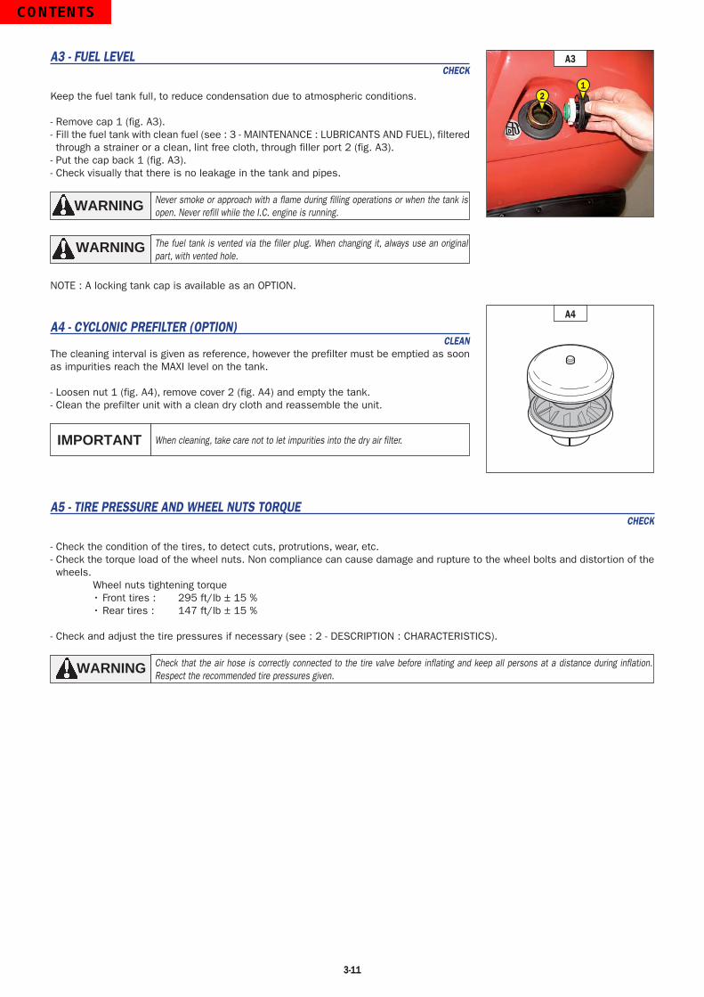
3-11
A3 - FUEL LEVELCHECK
Keep the fuel tank full, to reduce condensation due to atmospheric conditions.
- Remove cap 1 (fig. A3).- Fill the fuel tank with clean fuel (see : 3 - MAINTENANCE : LUBRICANTS AND FUEL), filtered through a strainer or a clean, lint free cloth, through filler port 2 (fig. A3).
- Put the cap back 1 (fig. A3).- Check visually that there is no leakage in the tank and pipes.
Never smoke or approach with a flame during filling operations or when the tank is open. Never refill while the I.C. engine is running.WARNING
The fuel tank is vented via the filler plug. When changing it, always use an original part, with vented hole.
WARNING
NOTE : A locking tank cap is available as an OPTION.
A4 - CYCLONIC PREFILTER (OPTION)CLEAN
The cleaning interval is given as reference, however the prefilter must be emptied as soon as impurities reach the MAXI level on the tank.
- Loosen nut 1 (fig. A4), remove cover 2 (fig. A4) and empty the tank.- Clean the prefilter unit with a clean dry cloth and reassemble the unit.
When cleaning, take care not to let impurities into the dry air filter.IMPORTANT
A5 - TIRE PRESSURE AND WHEEL NUTS TORQUECHECK
- Check the condition of the tires, to detect cuts, protrutions, wear, etc.- Check the torque load of the wheel nuts. Non compliance can cause damage and rupture to the wheel bolts and distortion of the wheels.
Wheel nuts tightening torque • Front tires : 295 ft/lb ± 15 % • Rear tires : 147 ft/lb ± 15 %
- Check and adjust the tire pressures if necessary (see : 2 - DESCRIPTION : CHARACTERISTICS).
Check that the air hose is correctly connected to the tire valve before inflating and keep all persons at a distance during inflation. Respect the recommended tire pressures given.
WARNING
A4
A3
12

3-12
B - EVERY 50 HOURS SERVICECARRY OUT THE OPERATIONS DESCRIBED PREVIOUSLY AS WELL AS THE FOLLOWING OPERATIONS.
B1 - DRY AIR FILTER CARTRIDGECheck - Clean
In case of use in a heavily dust laden atmosphere, there are pre-filtration cartridges (see : 3 - MAINTENANCE : FILTERS CARTRIDGES AND BELTS). Also, the checking and cleaning schedule of the cartridge must be increased.
If the clogging indicator light comes on, clean the cartridge as quickly as possible (1 hour maximum). The cartridge must not be cleaned more than seven times, after which the cartridge must be changed.IMPORTANT
- For the disassembly and reassembly of the cartridge, see : 3 - MAINTENANCE : D3 - DRY AIR FILTER CARTRIDGE.- Clean the filter cartridge using a compressed air jet (max. pressure 40 psi) directed from the top to the bottom and from the inside towards the outside, at lease 1 1/2 in. from the cartridge wall.
- Cleaning is completed when there is no more dust on the cartridge.
Avoid tearing or making a hole in the cartridge. The cartridge must not be blown anywhere near the air filter box. Never clean the cartridge by tapping it against a hard surface. Your eyes must be protected during this intervention.
IMPORTANT
- Clean the cartridge seal surfaces with a damp, clean lint-free cloth and grease with a silicone lubricant.- Check visually the outer condition of the air filter and its mounts. Verify the condition of the hoses and their mounts also.
Do not clean the dry air filter cartridge by washing it in liquid. Do not clean the safety cartridge located inside the filter cartridge, change it for a new one if it is dirty or damaged.IMPORTANT
B2 - RADIATOR CORECLEAN
In a heavy dust atmosphere, clean the radiator core every day. Do not use a water jet or high-pressure steam as this could damage the radiator fins.
IMPORTANT
- Lift up the overhead guard or the cab (see : 2 - DESCRIPTION : INSTRUMENTS AND CONTROLS).
In order to prevent the radiator becoming clogged, clean the radiator with a compressed air jet directed from outside to inside. This is the only way to clean the core of debris.
B3 - FRONT WHEELS REDUCERS OIL LEVELCHECK
Park the lift truck on level ground with the I.C. engine stopped.
- Check the oil level on each front wheel reducer.- Place the level plugs 1 (fig. B3) into a horizontal position.- Remove one of the level plugs, the oil must be flush with the port.- If necessary, add oil (see : 3 - MAINTENANCE : LUBRICANTS AND FUEL) through the same port.
- Replace the level plug 1 and tighten it (fig. B3) (tightening torque 47 ft/lbs).
B3
1 1

3-13
B4 - TENSION AND ALIGNMENT OF THE MAST LIFTING CHAINSCHECK - ADJUST
Park the lift truck on level ground with the mast in a vertical position and the forks lifted at approximately 8 in.
- Check the alignment of the mast lifting chains between the carriage’s chain fasteners and the chain rollers.
- Manually verify the chain tension, if necessary adjust as following while ensuring that the carriage is perpendicular to the mast.
- Loosen the nut 1 (fig. B4).- Loosen the lock nut 2 (fig. B4) of the chain tension adjuster.- Adjust the tension by tightening or loosening the nut 3 (fig. B4) while checking the alignment of the lifting chains.
- Then block the lock nut 2 (fig. B4) and the nut 3 (fig. B4).- Retighten the nut 1 (fig. B4).
In case of technical problems, consult your dealer.
IMPORTANT
B5 - MASTGREASE
To be carried out weekly, if the lift truck has been operated for less than 50 hours during the week.
In the event of prolonged use in an extremely dusty or oxidizing atmosphere, change this interval to 10 working hours or every day.
IMPORTANT
Clean and lubricate the following points with grease (see : 3 - MAINTENANCE : LUBRICANTS AND FUEL) and remove the surplus.
1 - Lubricators of the articulation axles at the foot of the mast (2 lubricators) (fig. B5/1).
2 - Lubricators of the tilt cylinders foot axles (2 lubricators) (fig. B5/2).3 - Lubricators of the tilt cylinders head axles (2 lubricators) (fig. B5/3).
B4
1
2
3
B5/2
2
B5/3
3
B5/1
1

3-14
B6 - HYDRAULIC OIL LEVELCHECK
Park the lift truck on level ground with the I.C. engine stopped, the mast tilted backwards and lowered as far as possible.
- Refer to gauge 1 (fig. B6/1).- The oil level is correct when it is at the level of the red point.- If necessary, add oil (see : 3 - MAINTENANCE : LUBRICANTS AND FUEL).- Lift up the overhead guard or the cab (see : 2 - DESCRIPTION : INSTRUMENTS AND CONTROLS).
- Remove cap 2 (fig. B6/2).- Add oil by filler port 3 (fig. B6/2).
Use a clean funnel and clean the oil nozzle before filling.IMPORTANT- Put the cap back.- Check visually that there is no leakage on the tank and pipes.
Always maintain the oil level at maximum as cooling depends on the oil flowing through the tank.
B7 - WINDSCREEN WASHER LIQUID LEVELCHECK
- Lift up the overhead guard or the cab (see : 2 - DESCRIPTION : INSTRUMENTS AND CONTROLS).
- Check visually the level.- If necessary add windscreen washer liquid (see : 3 - MAINTENANCE : LUBRICANTS AND FUEL) by filler port 1 (fig. B7).
B8 - CAB DOOR (OPTION)GREASE
- Clean and lubricate the points 1 (8 lubricators) (fig. B8) with grease (see : 3 - MAINTENANCE : LUBRICANTS AND FUEL) and remove the surplus.
B6/1
1
B6/2
3
2
B7
1
B8
1

3-15
B9 - REAR AXLE GREASE
MSI 30 T Series 2-E3
- Clean and lubricate the following points with grease (see : 3 - MAINTENANCE : LUBRICANTS AND FUEL) and remove the surplus.
1 - Lubricators of the swivel pins (6 lubricators) (fig. B9/1).2 - Lubricators of the steering cylinder head axles (4 lubricators) (fig. B9/2).3 - Lubricators of the rear axle oscillation pin (2 lubricators) (fig. B9/3).
B9 - REAR AXLE GREASE
MH 25-4 T Series 2-E3
- Clean and lubricate the following points with grease (see : 3 - MAINTENANCE : LUBRICANTS AND FUEL) and remove the surplus.
1 - Lubricators of the swivel pins (4 lubricators) (fig. B9/1).2 - Lubricators of the steering cylinder head axles (4 lubricators) (fig. B9/1).3 - Lubricators of the rear axle oscillation pin (2 lubricators) (fig. B9/2).
B9/1
1
1
1
B9/2
2 2
B9/3
3
B9/2
3
B9/1
22
1
1

3-16
C - EVERY 200 HOURS SERVICECarry out the operations described previously as well as the following operations.
C1 - I.C. ENGINE OILDRAIN
C2 - I.C. ENGINE OIL FILTERCHANGE
Park the lift truck on level ground, let the I.C. engine run at idle for a few minutes, then stop the I.C. engine.
DRAINING THE OIL- Lift up the overhead guard or the cab (see: 2 - DESCRIPTION: INSTRUMENTS AND CONTROLS).
- Place a container under drain plug 1 (fig. C1/1) and unscrew the drain plug.- Remove filling plug 2 (fig. C1/2) to ensure that the oil is drained properly.
Dispose of the drain oil in an ecological manner.IMPORTANT
REPLACEMENT OF THE FILTER- Remove I.C. engine oil filter 3 (fig. C1/3) and discard the filter and the filter seal.- Clean the filter bracket with a clean, lint-free cloth.- Fill the new engine oil filter (see: 3 - MAINTENANCE: FILTERS CARTRIDGES AND BELTS) and lightly grease the seal.
- Fit the oil filter onto its holder.- Tighten the oil filter by hand pressure only and lock the filter in place by a quarter turn.
FILLING UP THE OIL- Install and tighten drain plug 1 (fig. C1/1) (tightening torque 25 ft/lb).- Fill up with oil (see: 3 - MAINTENANCE: LUBRICANTS AND FUEL) by filler port 4 (fig. C1/2).
NOTE: For this operation, we recommend you use a funnel fitted with a hose.
- Wait a few minutes to allow the oil to settle into the sump.- Start the I.C. engine and let it run for a few minutes.- Check for possible leaks at the drain plug and the oil filter.- Stop the I.C. engine, wait a few minutes and check the level against the upper mark on dipstick 5 (fig. C1/4).
- Top up the level if necessary.
C1/1
1
C1/2
2
C1/3
3
4
C1/4
5

3-17
C3 - FUEL FILTERCLEAN
- Lift up the overhead guard or the cab (see: 2 - DESCRIPTION: INSTRUMENTS AND CONTROLS).
- Close the fuel valve 1 (fig. C3/1) by setting to position B.- Carefully clean the outside of the pre-filter and its holder, to prevent dust from getting into the system.
- Unscrew the retaining ring 2, remove the housing 3 (fig. C3/2) and clean the inside using a brush immersed in clean diesel oil.
- Remove the cartridge filter 4 (fig. C3/2) and dip in diesel oil to rinse.- Reassemble the unit.- Open the fuel valve 1 (fig. C3/1) by setting to position A.- Bleed the fuel circuit (see: 3 - MAINTENANCE: G1 - FUEL SYSTEM).
Dust and impurities in the fuel will cause the injection pump and injectors to wear more quickly. To avoid this, regularly clean the fuel filter.IMPORTANT
C4 - ALTERNATOR/FAN/CRANKSHAFT BELT TENSIONCHECK - ADJUST
- Lift up the overhead guard or the cab (see: 2 - DESCRIPTION: INSTRUMENTS AND CONTROLS).
- Check the belt for signs of wear and cracks and change if necessary (see: 3 - MAINTENANCE: FILTERS CARTRIDGES AND BELTS).
- Check the belt tension between the pulleys of the crankshaft and of the alternator.- Under pressure applied by the thumb, the tension should be between 1/4 and 3/8 in. (fig. C4/1).
- Carry out adjustments if necessary.- Loosen screws 1 (fig. C4/2) by two to three thread turns.- Swivel the alternator assembly so as to obtain the belt tension required.- Retighten screws 1 (fig. C4/2).
If the alternator belt has to be changed, check the tension again after the first 20 hours of operation.
IMPORTANT
C3/1
A
B1
C4/1
C3/2
4
3
2
C4/2
1
1

3-18
D - EVERY 500 HOURS SERVICECarry out the operations described previously as well as the following operations.
D1 - DRY AIR FILTER CARTRIDGECHANGE
In case of use in a heavily dust laden atmosphere, there are pre-filtration cartridges, see: 3 - MAINTENANCE: FILTERS CARTRIDGES AND BELTS. Also, checking and cleaning the cartridge must be increased (every 250 hours in a heavily laden dust atmosphere and with pre-filtration).
Change the cartridge in a clean location, with the I.C. engine stopped. Never run the I.C. engine with the air filter removed or damaged.
IMPORTANT- Lift up the overhead guard or the cab (see: 2 - DESCRIPTION: INSTRUMENTS AND CONTROLS).- Loosen the bolts and remove cover 1 (fig. D1).- Gently remove the cartridge 2 (fig. D1), taking care to avoid spilling the dust.- Leave the safety cartridge in place.- The following parts must be cleaned with a damp, clean lint-free cloth.
- The inside of the filter and cover.- The inside of the filter inlet hose.- The gasket surfaces in the filter and in the cover.
- Check pipes and connections between the air filter and the I.C. engine and the connection and condition of the clogging indicator on the filter.
- Before installing check the state of the new cartridge (see: 3 - MAINTENANCE: FILTERS CARTRIDGES AND BELTS).- Introduce the cartridge into the filter axis and push it in, pressing the edges and not the middle.- Reassemble the cover, guiding the valve downwards.
D2 - FUEL FILTER CARTRIDGECHANGE
- Lift up the overhead guard or the cab (see: 2 - DESCRIPTION: INSTRUMENTS AND CONTROLS).
- Carefully clean the outside of the filter and its holder, to prevent dust from getting into the system.
- Close the fuel valve 1 (fig. D2/1) by setting to position B.- Unscrew the retaining ring 2, remove the housing 3 (fig. D2/2) and clean the inside using a brush immersed in clean diesel oil.
- Discard the filter cartridge 4 (fig. D2/2).- Install a new cartridge (see: 3 - MAINTENANCE: FILTERS CARTRIDGES AND BELTS).
D1
2
1
D2/1
A
B1
D2/2
4
3
2

3-19
D3 - FUEL PRE-FILTERCHANGE
- Take the pre-filter 1 from the clip 2 (fig. D3/1).- Remove and discard the pre-filter 1 (fig. D3/2).- Fit a new pre-filter (see: 3 - MAINTENANCE: FILTERS CARTRIDGES AND BELTS).- Place the new pre-filter under the clip 2 (fig. D3/1).- Open the fuel valve 1 (fig. D2/1) by setting to position A.
D4 - ALTERNATOR/FAN/CRANKSHAFT BELTCHANGE
- Lift up the overhead guard or the cab (see: 2 - DESCRIPTION: INSTRUMENTS AND CONTROLS).- Loosen screws 1 (fig. D4) by two to three thread turns.- Swivel the alternator assembly so as to loosen the belt 2 (fig. D4) and replace with a new one (see: 3 - MAINTENANCE: FILTERS CARTRIDGES AND BELTS).
- Adjust the belt tension between the crankshaft and alternator pulleys.- Under pressure applied by the thumb, the tension should be between 1/4 to 3/8 in.- Re-tighten the screws 1 (fig. D4).
When installing a new alternator belt, check the tension again after the first 20 hours of operation.
IMPORTANT
D3/1
21
D3/2
1
D4
1
1
2

3-20
D5 - MAST LIFTING CHAINSCLEAN - CHECK - GREASE
- Wipe the mast lifting chains 1 (fig. D5) with a clean, lint-free cloth, then examine them closely for any signs of wear.
- Vigorously brush the chains to get rid of any foreign matter, use a stiff nylon brush and clean diesel fuel.
- Rinse the chains with a paint brush impregnated with clean diesel fuel and dry them with a compressed air jet.
- Moderately lubricate the chains (see: 3 - MAINTENANCE: LUBRICANTS AND FUEL).
In case of technical problems, consult your dealer.
IMPORTANT
D6 - HYDRAULIC RETURN OIL FILTER CARTRIDGECHANGE
Stop the I.C. engine and remove the pressure from the circuits by working the hydraulic controls.
Thoroughly clean the outside of the filter and its surroundings before any intervention, to prevent risk of polluting the hydraulic circuit.
IMPORTANT- Lift up the overhead guard or the cab (see: 2 - DESCRIPTION: INSTRUMENTS AND CONTROLS).- Remove the plug 1 (fig. D6/1).- Move the windscreen washer fluid tank to one side and unscrew the cap 2 (fig. D6/2) two to three turns.
- Wait a few moments while the oil flows into the tank.- Remove the cover and take out filter cartridge assembly 3 (fig. D6/3).- Place the assembly in a clean container and empty the bowl.- Remove the bowl 4 and the top 5 of the filter cartridge 6 (fig. D6/4) by a movement of rotation.- Install the bowl and the top onto a new cartridge (see: 3 - MAINTENANCE: FILTER ELEMENTS AND BELTS).
- Fit the assembly in place and retighten the cover 2 (fig D6/2).- Put the cap back 1 (fig. D6/1).
D5
1
D6/1
1
D6/2
2
D6/3
3
D6/4
5
6
4

3-21

3-22
E - EVERY 1000 HOURS SERVICECarry out the operations described previously as well as the following operations.
E1 - FUEL TANKCLEAN
E2 - FUEL TANK BREATHERCHANGE
While carrying out these operations, do not smoke or work near a flame.WARNING
Park the lift truck on level ground with the I.C. engine stopped.
- Inspect the fuel circuit and tank for leaks.- In the event of a leak, contact your dealer.
Never perform welding on the fuel system, this could cause an explosion or a fire.WARNING
- Place a container under drain plug 1 (fig. E1/1) and unscrew the plug.- Remove filling plug 2 (fig. E1/2) in order to ensure the fuel is drained properly.- Rinse out with 2.5 gallons of clean diesel through filler port 3 (fig. E1/2).- Install and tighten the drain plug (tightening torque 25 ft/lbs).- Fill the fuel tank with clean diesel filtered through the filler port.- Install the filling cap.- Remove the breather 4 from the underside of the counterweight 5 (fig. E1/3).- Dismantle the breather and replace with a new one (see: 3 - MAINTENANCE: FILTERS CARTRIDGES AND BELTS).
- Position the new breather beneath the counterweight 5 (fig. E1/3).- If necessary, bleed the fuel circuit (see: 3 - MAINTENANCE: G1 - FUEL SYSTEM).
E3 - SAFETY DRY AIR FILTER CARTRIDGECHANGE
- For the disassembly and reassembly of the dry air filter cartridge, see: 3 - MAINTENANCE: D1 - AIR FILTER CARTRIDGE.
- Gently remove the dry air filter safety cartridge 1 (fig. E3), taking care to avoid spilling the dust.- Clean the gasket surface on the filter with a damp, clean lint-free cloth.- Before installing, check the state of the new safety cartridge (see: 3 - MAINTENANCE: FILTERS AND BELTS).
- Introduce the cartridge into the filter axis and push it in, pressing the edges and not the middle.
NOTE: The period for changing the safety cartridge is given for reference only. It must be changed for every two changes of the dry air filter cartridge.
E1/1
1
E1/2
23
E3
1
E1/3
4 5

3-23
E4 - HYDRAULIC OILDRAIN
E5 - SUCTION STRAINER FOR HYDRAULIC OIL TANKCLEAN
E6 - FILTER CAP FOR HYDRAULIC OIL TANKCHANGE
Park the lift truck on level ground, the I.C. engine stopped and the mast lowered as far as possible.
Thoroughly clean the outside of the filter and its surroundings before any intervention, to prevent risk of polluting the hydraulic circuit.
IMPORTANT
DRAINING THE OIL- Lift up the overhead guard or the cab (see : 2 - DESCRIPTION : INSTRUMENTS AND CONTROLS).
- Place a container under drain plug 1 (fig. E4/1) and unscrew the plug.- Remove filler cap 2 (fig. E4/2) in order to ensure that the oil is drained properly.
Dispose of the drain oil in an ecological manner.IMPORTANT
CLEANING THE STRAINER- Disconnect the clogging indicator 3 (fig. E4/3).- Disconnect the hoses 4 (fig. E4/3) at the level of the hydraulic return oil filter 5 (fig. E4/3).
- Unscrew the four screws 6 (fig. E4/3) and remove the complete filter 5 (fig. E4/3).- Unscrew the suction strainer at the bottom of the tank, clean it with the help of a compressed air jet, check its condition and change it, if necessary (see : 3 - MAINTENANCE : FILTERS CARTRIDGES AND BELTS).
- Reassemble the strainer, the filter and re-connect the hoses and the clogging indicator.
FILLING UP THE OIL- Clean and install drain plug 1 (fig. E4/1) (tightening torque 25 ft/lbs).- Fill up with oil (see : 3 - MAINTENANCE : LUBRICANTS AND FUEL) by filler port 7 (fig. E4/2).
Use a clean funnel and clean the oil nozzle before filling.IMPORTANT
- Observe the oil level on dipstick 8 (fig. E4/4) ; the oil level should be at the level of the red point.
- Check for any possible leaks at the drain plug.- Replace filler plug 2 (fig. E4/2) with a new filler plug (see : 3 - MAINTENANCE : FILTERS CARTRIDGES AND BELTS).
POLLUTION ABATEMENT OF THE HYDRAULIC CIRCUIT- Let the I.C. engine run (accelerator pedal at halfway travel) for 5 minutes without using anything on the lift truck, then for 5 more minutes while using all the hydraulic movements (except the steering system).
- Accelerate the engine at full speed for 1 minute, then activate the steering system.- This operation makes a pollution abatement of the circuit possible through the hydraulic return oil filter.
E4/1
1
E4/2
7
2
E4/4
8
E4/3
3
46
6
4
5

3-24
E7 - SEAT BELTCHECK
SEAT BELT WITH TWO ANCHORING POINTS- Check the following points:
• Fixing of the anchoring points on the seat.• Cleanness of the strap and the locking mechanism.• Triggering of the locking mechanism.• Condition of the strap (cuts, curled edges).
REELED SEAT BELT WITH TWO ANCHORING POINTS- Check the points listed above together with the following points :
• The correct winding of the belt.• Condition of the reel guards.• Roller locking mechanism when the strap is given a sharp tug.
NOTE : After an accident, replace the seat belt.
Under no circumstances should you use the lift truck if the seat belt is damaged! Repair or replace the seat belt immediately!WARNING

3-25

3-26
F1/1
1
F1/2
2
F1/33
4
F1/4
5
6
F - EVERY 2000 HOURS OF SERVICECarry out the operations described previously as well as the following operations.
F1 - COOLING LIQUIDDRAIN
These operations are to be carried out if necessary or every two years at the beginning of winter. Park the lift truck on level ground with the I.C. engine stopped and cold.
DRAINING THE LIQUID- Lift up the overhead guard or the cab (see: 2 - DESCRIPTION: INSTRUMENTS AND CONTROLS).- Disassemble the lower hose 1 (fig. F1/1) of the radiator.- Unscrew the filler plug 2 (fig. F1/2) of the expansion tank and empty.- Remove the pre-filter 3 and the cover plate 4 (fig. F1/3).- Remove filling plug 5 (fig. F1/4) of the radiator.- Let the cooling circuit drain entirely while ensuring that the ports are not clogged.- Check the condition of the hoses as well as the fastening devices and change the hoses if necessary.
- Rinse the circuit with clean water and use a cleaning agent if necessary.
FILLING THE LIQUID- Reassemble the lower hose 1 (fig. F1/1).- Slowly fill the circuit with the cooling liquid (see: 3 - MAINTENANCE: LUBRICANTS AND FUEL) through the filler port 6 (fig. F1/4).
- Fill the expansion tank to the maximum level.- Run the I.C. engine at idle for a few minutes.- Check for any possible leaks.- Check the level and refill if necessary.- Install filling plug 5 (fig. F1/4).- Reassemble the cover plate 4 and the pre-filter 3 (fig. F1/3).- Retighten filler cap 2 (fig. F1/2).
To prevent corrosion the I.C. engine cooling system must be filled with a minimum mixture of 25 % ethylene glycol-based antifreeze.IMPORTANT

3-27
F2 - FRONT WHEELS REDUCERS OILDRAIN
This operation should be carried out once a year if the lift truck has not reached 2000 hours service within the year.
Park the lift truck on level ground with the I.C. engine stopped and the reducers oil still warm.
Dispose of the drain oil in an ecological manner.IMPORTANT
- Drain and change the oil on each front wheel reducer.- Place drain plug 1 (fig. F2) in position A.- Place a container under the drain plug and unscrew the plug.- Let the oil drain fully.- Place the drain port in position B, i.e. in a level port.- Fill up with oil (see : 3 - MAINTENANCE : LUBRICANTS AND FUEL) by level port 1 (fig. F2).- The level is correct when the oil level is flush with the edge of the hole.- Install and tighten the drain plug 1 (fig. F2) (tightening torque 47 ft/lbs).
F2
1
B
A

3-28
G - OCCASIONAL MAINTENANCE
G1 - FUEL SYSTEMBLEED
These operations are to be carried out only in the following cases:- A component of the fuel system replaced or drained.- A drained tank.- Running out of fuel.Ensure that the level of fuel in the tank is sufficient and bleed in the following order:
- Lift up the overhead guard or the cab (see: 2 - DESCRIPTION: INSTRUMENTS AND CONTROLS).
BLEEDING THE FUEL FILTER- Loosen bleed screw 1 (fig. G1/1).- Switch on the lift truck ignition until the diesel oil flows from the bleeder screw free of any air.- Tighten the bleed screw while the diesel fuel is flowing out.
BLEEDING THE INJECTION PUMP- Open the bleed valve 2 (fig. G1/2).- Switch on the lift truck ignition until the diesel oil flows from the bleeder screw free of any air.
- Seal the bleed valve while the diesel oil is flowing.
The I.C. engine is then ready to be started up.
NOTE: If the I.C. engine functions correctly for a short time then stops or functions irregularly, check for possible leaks in the low pressure circuit. If in doubt, contact your dealer.
G1/1
1
G1/2
2

3-29
G2 - WHEELCHANGE
- Park the lift truck, if possible on even and hard ground.- Put the warning lights on (option).- Immobilize the lift truck in both directions on the axle opposite to the wheel to be changed.
- Unlock the nuts of the wheel to be changed.
REAR WHEELFor this operation, we advise you to use an approved hydraulic jack.
- Place the jack under the counterweight. It must be situated in the middle and under the flat part of the counterweight (fig. G2/1).
- Lift the wheel until it lifts off the ground and fit security wedges under the rear axle (fig. G2/2).
- Completely unscrew the wheel nuts and remove them.- Free the wheel by reciprocating movements and roll it to the side.- Slip the new wheel on the wheel hub.- Install the nuts by hand, if necessary grease them.- Remove the security wedges and lower the lift truck with the jack.- Tighten the wheel nuts with a torque wrench (see : 3 - MAINTENANCE : A - DAILY OR EVERY 10 HOURS SERVICE for tightening torque).
FRONT WHEEL- Lift the carriage and tilt the mast backwards.- Put wedges under the foot of the mast on the side of the wheel to be changed (fig. G2/3).
- Tilt the mast forwards so as to lift the wheel.- Place wedges under the chassis as near as possible to the wheel (fig. G2/4).- Completely loosen the wheel nuts and remove them.- Remove the wheels by reciprocating movements and roll it on the side.- Slide the new wheel onto the hub.- Manually start the nuts, if necessary lubricate them.- Remove the wedges under the axle and lower the lift truck.- Tighten the wheel nuts with a torque wrench (see : 3 - MAINTENANCE : A - DAILY OR EVERY 10 HOURS SERVICE for tightening torque).
G2/1
G2/2
G2/3
G2/4

3-30
G3 - RAISING THE OVERHEAD GUARD OR THE CAB IN THE EVENT OF A BREAKDOWN
PROCEDURE IN THE EVENT OF HYDRAULIC FAILURE ON THE LIFTING SYSTEM
UNLOCKING THE OVERHEAD GUARD OR THE CAB:- Unlock the overhead guard by means of the lever 1 (fig. A) in position A.- With the cab model, close the doors.
RAISING THE OVERHEAD GUARD OR THE CAB:
Check that there is nothing laying on the driver’s seat or in the cab which could disrupt the operation of raising the cab.
CAUTION
- If necessary, raise the mast until it is approximately 20 in. above the overhead guard or the cab.- Unscrew the two screws 2 (fig. G3/2) on the roof and replace them with two eyes 3 (fig. G3/3).
- Pass a sling 4 around the mobile upright’s upper belt and fasten the ends of the sling onto the eyes 3 (fig. G3/3).
- Switch on the engine.- Gently raise the mast to tension the sling and raise the overhead guard or the cab about an inch.
- Return the lever 1 (fig. G3/1) to its initial position (position B).- Tilt the mast forwards and raise it slowly until you can insert the safety stay 5 (fig. G3/4) - Lower the mast to release and remove the sling.
G3/3
34
G3/4
5
G3/1
1
BA
G3/2
22

3-31
G4 - BREAKDOWN OF BATTERY
- Remove the exhaust pipe 1 (fig. G4/1).- Remove the cowl 2 (fig. G4/1) to access the battery 3 (fig. G4/2).- Bring an extra battery of the same type as the one used for the lift truck and battery cables.- Connect the extra battery while respecting the polarity.- Then, carry out the lifting of the overhead guard or cab (see: 2 - DESCRIPTION: INSTRUMENTS AND CONTROLS).
- Change the battery.
Handling and servicing a battery can be dangerous, take the following precautions : - Wear protective goggles. - Keep the battery horizontal. - Never smoke or work near an open flame. - Work in a well-ventilated area. - In the event of electrolyte being spilled onto the skin or splashed in the eyes,
rinse thoroughly with cold water for 15 minutes and call a doctor.
WARNING
G5 - FRONT HEADLAMPS (OPTION)ADJUST
RECOMMENDED SETTING(as per standard ECE-76/756 76/761 ECE20)Set to - 2% of the dipped beam in relation to the horizontal line of the headlamp.
ADJUSTING PROCEDURE- Park the lift truck unloaded, in the transport position, and perpendicular to a white wall on flat, level ground (fig. G5).- Check the tire pressures (see: 2 - DESCRIPTION: CHARACTERISTICS).
- Put the gear reverser lever in neutral and release the parking brake.
CALCULATING THE HEIGHT OF THE DIPPED BEAM (H2)• h1 = Height of the dipped beam in relation to the ground.• h2 = Height of the adjusted beam.• l = Distance between the dipped beam and the white wall.
MADE IN FRANCE
h1
+%
-%
h1h2
-2%
h2 = h1 - (l x 2 / 100)
l
G5
G4/1
1
2
G4/2
3

3-32
G6 - LIFT TRUCK TOWING
MSI 30 T Series 2-E3
NEVER try to push or pull the lift truck to start it! Such a maneuver would cause seri-ous damage to the hydrostatic transmission.
You must first remove the wheel reducers before any towing:
IMPORTANT
DANGER
While the wheel reducers are removed the forklift has no braking system! Properly block all wheels or secure the forklift to a drawbar and towing vehicle before removing
the wheel reducers!Tag the forklift, noting that it does not have a braking system.
The lift truck must be towed at very slow speed (less than 3mph) over the shortest possible distance (less than 328 ft.).IMPORTANT
- To tow a lift truck, the wheel reducers 1 (fig. G6/1) must be unlocked to avoid damaging the hydrostatic transmission. Towing the lift truck must be carried out by means of a rigid drawbar, because the lift truck is uncoupled from its braking system after unlocking the wheel reducers.
UNLOCKING THE FRONT WHEEL REDUCERSCarry out this operation on both front wheel reducers.- Place a container under the reducer.- Disassemble the retaining ring 1 (fig. G6/1).- Remove the plug 2 (fig. G6/1), a little oil will escape.- Put a bolt HM 6 x .. onto the threading of the drive shaft 3 (fig. G6/2).- Remove the drive shaft and protect it with a clean cloth.- Reassemble the plug 2 (fig. G6/1) and the retaining ring 1 (fig. G6/1) to protect the wheel reducers during the towing.
TOWING THE LIFT TRUCK- Release the hand brake.- Turn on the warning lights (option).- Because the power steering will not function, steering will be difficult, turn the wheel slowly. Avoid abrupt movements and jerks.- After towing, proceed in the reverse order to install the wheel reducers.
NOTE: When reassembling, ensure that the drive shaft grooves and the gears coincide without forcing.
- Top up the level of oil in the wheel reducers (see : 3 - MAINTENANCE: B4 - FRONT WHEELS REDUCERS OIL LEVEL).
G6/2
3
G6/1
1
2
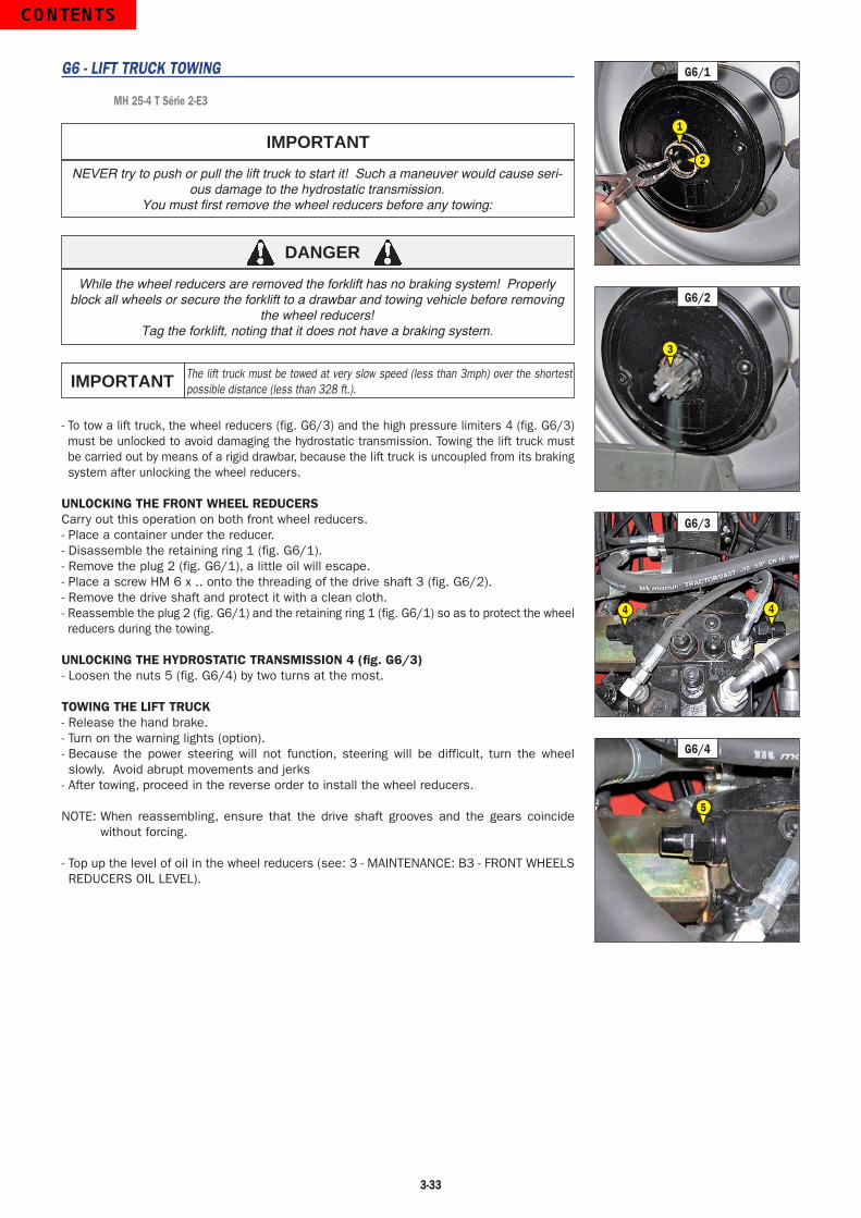
3-33
G6 - LIFT TRUCK TOWING
MH 25-4 T Série 2-E3
NEVER try to push or pull the lift truck to start it! Such a maneuver would cause seri-ous damage to the hydrostatic transmission.
You must first remove the wheel reducers before any towing:
IMPORTANT
DANGER
While the wheel reducers are removed the forklift has no braking system! Properly block all wheels or secure the forklift to a drawbar and towing vehicle before removing
the wheel reducers!Tag the forklift, noting that it does not have a braking system.
The lift truck must be towed at very slow speed (less than 3mph) over the shortest possible distance (less than 328 ft.).IMPORTANT
- To tow a lift truck, the wheel reducers (fig. G6/3) and the high pressure limiters 4 (fig. G6/3) must be unlocked to avoid damaging the hydrostatic transmission. Towing the lift truck must be carried out by means of a rigid drawbar, because the lift truck is uncoupled from its braking system after unlocking the wheel reducers.
UNLOCKING THE FRONT WHEEL REDUCERSCarry out this operation on both front wheel reducers.- Place a container under the reducer.- Disassemble the retaining ring 1 (fig. G6/1).- Remove the plug 2 (fig. G6/1), a little oil will escape.- Place a screw HM 6 x .. onto the threading of the drive shaft 3 (fig. G6/2).- Remove the drive shaft and protect it with a clean cloth.- Reassemble the plug 2 (fig. G6/1) and the retaining ring 1 (fig. G6/1) so as to protect the wheel reducers during the towing.
UNLOCKING THE HYDROSTATIC TRANSMISSION 4 (fig. G6/3)- Loosen the nuts 5 (fig. G6/4) by two turns at the most.
TOWING THE LIFT TRUCK- Release the hand brake.- Turn on the warning lights (option).- Because the power steering will not function, steering will be difficult, turn the wheel slowly. Avoid abrupt movements and jerks
- After towing, proceed in the reverse order to install the wheel reducers.
NOTE: When reassembling, ensure that the drive shaft grooves and the gears coincide without forcing.
- Top up the level of oil in the wheel reducers (see: 3 - MAINTENANCE: B3 - FRONT WHEELS REDUCERS OIL LEVEL).
G6/3
44
G6/4
5
G6/2
3
G6/1
1
2
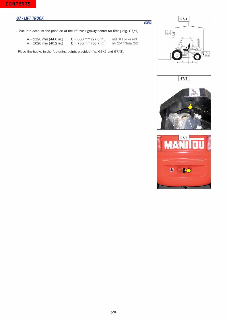
3-34
G7 - LIFT TRUCK SLING
- Take into account the position of the lift truck gravity center for lifting (fig. G7/1).
A = 1120 mm (44.0 in.) B = 680 mm (27.0 in.) MSI 30 T Series 2-E3A = 1020 mm (40.2 in.) B = 780 mm (30.7 in) MH 25-4 T Series 2-E3
- Place the hooks in the fastening points provided (fig. G7/2 and G7/3).MADE IN FRANCE
A B
G7/1
G7/2
G7/3
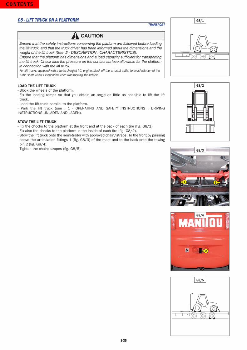
3-35
G8 - LIFT TRUCK ON A PLATFORM TRANSPORT
Ensure that the safety instructions concerning the platform are followed before loading the lift truck, and that the truck driver has been informed about the dimensions and the weight of the lift truck (See 2 - DESCRIPTION : CHARACTERISTICS).Ensure that the platform has dimensions and a load capacity sufficient for transporting the lift truck. Check also the pressure on the contact surface allowable for the platform in connection with the lift truck.For lift trucks equipped with a turbo-charged I.C. engine, block off the exhaust outlet to avoid rotation of the turbo shaft without lubrication when transporting the vehicle.
CAUTION
LOAD THE LIFT TRUCK- Block the wheels of the platform.- Fix the loading ramps so that you obtain an angle as little as possible to lift the lift truck.
- Load the lift truck parallel to the platform.- Park the lift truck (see : 1 - OPERATING AND SAFETY INSTRUCTIONS : DRIVING INSTRUCTIONS UNLADEN AND LADEN).
STOW THE LIFT TRUCK- Fix the chocks to the platform at the front and at the back of each tire (fig. G8/1).- Fix also the chocks to the platform in the inside of each tire (fig. G8/2).- Stow the lift truck onto the semi-trailer with approved chain/straps. To the front by passing above the articulation fittings 1 (fig. G8/3) of the mast and to the back onto the towing pin 2 (fig. G8/4).
- Tighten the chain/strapes (fig. G8/5).
G8/1
G8/2
G8/5
G8/4
2
G8/3
1 1

3-36