Manifold
24
Model M26 Manifold line for 266 pressure transmitters Data Sheet DS/M26-EN Comprehensive wetted material portfolio Accessories available Bolts and brackets allow multiple installations and grant full transmitter support. Tee bars easily manoeuvrable 2600T Series Pressure Transmitters Engineered solutions for all applications Tailored manifold to meet user’s needs Perfect interface between process and transmitter thanks to the most common connection types. Colour coded functional identification
-
Upload
pradeep123456 -
Category
Documents
-
view
113 -
download
3
Transcript of Manifold

Model M26Manifold line for 266 pressure transmitters
Data Sheet DS/M26-EN
Comprehensive wetted material portfolio
Accessories availableBolts and brackets allow multiple installations and grant full transmitter support.
Tee bars easily manoeuvrable
2600T Series Pressure TransmittersEngineered solutions for allapplications
Tailored manifold to meet user’s needs
Perfect interface between process and transmitter thanks to the most common connection types.
Colour coded functional identification

2 DS/M26-EN | 2600T Series Pressure transmitters Manifold line S26
Model M26Manifold line for 266 pressure transmitters
Functional SpecificationsManifold pressure rating vs. process temperature:Standard PTFE packing
ImportantPlease ask for a supplementary check if your application is close to the limits shown in the above picture (230°C and/or 6000 psi).
Important The maximum working temperature of the whole assembly (manifold and instrument) corresponds to the temperature limit of the pressure transmitter.
Important When the maifold is assembled to a 2600T pressure transmitter with NACE compliance A4-50 Stainless Steel bolts (available on request), please note that the maximum working pressure is limited to 210 bar (3045 psi).
PTFE propertiesMechanical propertiesPTFE has good tensile properties different from other plastic materials as it may be used over a wide temperature range from – 250°C to +250°C ( -418°F to +482°F ) . PTFE shows the lowest friction values compared to other plastic materials. Furthermore, being the static friction values almost equal to the dynamic friction values, there is no tendency to seizure within a sliding system situation, and therefore no detachment friction.
Electrical propertiesPTFE has very good electrical properties. Dielectric strength is excellent and remains unchanged even at high temperature, it only decreases depending on the material thickness and on the electrical frequency values. Dielectric constant values and dissipation factor are among the lowest values and remain unchanged even at high temperatures and at a wide frequency range. Good resistance to arc and corona effect.
Other propertiesPTFE surfaces are highly anti adhesive and do not absorb moisture. PTFE is non-toxic and can be used in contact with food. There are some limitations only for some kinds of filled PTFE due to the toxicity of some filling elements ( i.e. heavy metals and its compounds ) .
Standard suppied partsM26 manifolds are always supplied with:- PTFE gaskets for transmitter connection (for flanged models)- 1 or 2 Plugs 1/4“ NPT-M (according to the selected model)- Carbon Steel bolts- Certificate of compliance with the order EN10204-2.1- Inspection certificate EN 10204-3.1 of manifold body only.
External agents resistancePTFE is considered inert towards nearly all known chemical elements and it is insoluble in all solvents. It is only attached by elemental alkali metals, and by Chlorine Trifluoride and elemental Fluorine at high temperatures and pressures. Fluorinated hydrocarbons can have a swelling effect on PTFE but it is a reversible situation, while some fluorinated oils, around 300°C ( 5 72°F ) temperature, swell anddissolve PTFE. PTFE is completely untouched by light and atmospheric agents. Its resistance to nuclear radiations is rather low, it is affected by it starting from 105 rad. with a lowering of the tensile properties.

2600T Series Pressure transmitters Manifold line M26 | DS/M26-EN 3
(*) The mounting bracket kit contains:bracket, U-bolts, cap screws, nuts, lock washers, spacers and assembling instruction.
Physical Specification(Refer to ordering information sheets for options related to specific model or versions code)MaterialsBody, bonnet and nutAISI 316 L ss; Hastelloy C-276™; Monel 400™; Inconel 625Mounting bracket (*)Zinc plated carbon steel; AISI 316 L ss.Gaskets PTFE, other available on request.BoltsZinc plated carbon steel; AISI 316 ss bolts and nuts Class A4–50 per UNI 7323 (ISO 3506), in compliance with NACE MR0175 Class II (as option).
Made in Italy

4 DS/M26-EN | 2600T Series Pressure transmitters Manifold line S26
Model M26Manifold line for 266 pressure transmitters
Two-valve manifold configurations(Refer to ordering information sheets for options related to specific model or versions code)
M26.P.A.S.2.V. - Two-valve bar stock manifold. Threaded connections
Inlet (process connection) 1/2 in. - 14 NPT male
Outlet (transmitter side) 1/2 in. - 14 NPT female
Drain 1/4 in. - 18 NPT female
Packing PTFE
Rating 690 bar (69 MPa, 10000 psi)
Included accessory 1 plug 1/4 in. - 18 NPT male
M26.P.A.S.2.V. - Two-valve bar stock manifold. Threaded connections
Inlet (process connection) 1/2 in. - 14 NPT female
Outlet (transmitter side) 1/2 in. - 14 NPT male
Drain 1/4 in. - 18 NPT female
Packing PTFE
Rating 690 bar (69 MPa, 10000 psi)
Included accessory 1 plug 1/4 in. - 18 NPT male
M26.P.A.S.2.V. - Two-valve bar stock manifold. Threaded connections
Inlet (process connection) 1/2 in. - 14 NPT male
Outlet (transmitter side) 1/2 in. - 14 NPT male
Drain 1/4 in. - 18 NPT female
Packing PTFE
Rating 690 bar (69 MPa, 10000 psi)
Included accessory 1 plug 1/4 in. - 18 NPT male
Note:
For details about the correct codification of each single model of manifold,
please refer to the ordering information at the end of this document.

2600T Series Pressure transmitters Manifold line M26 | DS/M26-EN 5
M26.P.A.S.2.V. - Two-valve bar stock manifold. Threaded connections
Inlet (process connection) 1/2 in. - 14 NPT female
Outlet (transmitter side) 1/2 in. - 14 NPT female
Drain 1/4 in. - 18 NPT female
Packing PTFE
Rating 690 bar (69 MPa, 10000 psi)
Included accessory 1 plug 1/4 in. - 18 NPT male
M26.D.A.S.2.V. - Two-valve bar stock manifold for DP Style transmitters
Body configuration For standard flanges transmitters
Inlet (process connection) 1/2 in. - 14 NPT female
Outlet (transmitter side) Flanged according IEC61518/B
Drain 1/4 in. - 18 NPT female
Packing PTFE
Rating 413.3 bar (41.37 MPa, 6000 psi)
Included accessories
1 plug 1/4 in. - 18 NPT male
1 PTFE gasket for transmitter flanged
side (IEC61518/B)
2 Carbon steel screws 7/16 in. UNF
(lenght 2 in.)
M26.D.A.V.2.V. - Two-valve bar stock manifold for DP Style transmitters
Body configuration For vertical flanges transmitters
Inlet (process connection) 1/2 in. - 14 NPT female
Outlet (transmitter side) Flanged according IEC61518/B
Drain 1/4 in. - 18 NPT female
Packing PTFE
Rating 413.3 bar (41.37 MPa, 6000 psi)
Included accessories
1 plug 1/4 in. - 18 NPT male
1 PTFE gasket for transmitter flanged
side (IEC61518/B)
2 Carbon steel screws 7/16 in. UNF
(lenght 1 3/4 in.)
Note:
For details about the correct codification of each single model of manifold,
please refer to the ordering information at the end of this document.

6 DS/M26-EN | 2600T Series Pressure transmitters Manifold line S26
Model M26Manifold line for 266 pressure transmitters
Three-valve manifold configurations(Refer to ordering information sheets for options related to specific model or versions code)
M26.D.A.S.3.V. - Three-valve bar stock manifold for DP transmitters
Body configuration For standard flanges transmitters
Inlet (process connection) 1/2 in. - 14 NPT female
Outlet (transmitter side) Flanged according IEC61518/B
Drain 1/4 in. - 18 NPT female
Packing PTFE
Rating 413.3 bar (41.37 MPa, 6000 psi)
Included accessories
2 plug 1/4 in. - 18 NPT male
2 PTFE gasket for transmitter flanged
side (IEC61518/B)
4 Carbon steel screws 7/16 in. UNF
(lenght 2 in.)
M26.D.A.V.3.V. - Three-valve bar stock manifold for DP transmitters
Body configuration For vertical flanges transmitters
Inlet (process connection) 1/2 in. - 14 NPT female
Outlet (transmitter side) Flanged according IEC61518/B
Drain 1/4 in. - 18 NPT female
Packing PTFE
Rating 413.3 bar (41.37 MPa, 6000 psi)
Included accessories
2 plug 1/4 in. - 18 NPT male
2 PTFE gasket for transmitter flanged
side (IEC61518/B)
4 Carbon steel screws 7/16 in. UNF
(lenght 1 3/4 in.)
Note:
For details about the correct codification of each single model of manifold,
please refer to the ordering information at the end of this document.

2600T Series Pressure transmitters Manifold line M26 | DS/M26-EN 7
Five-valve manifold configurations(Refer to ordering information sheets for options related to specific model or versions code)
M26.D.A.S.5.V. - Five-valve bar stock manifold for DP transmitters
Body configuration For standard flanges transmitters
Inlet (process connection) 1/2 in. - 14 NPT female
Outlet (transmitter side) Flanged according IEC61518/B
Drain 1/4 in. - 18 NPT female
Packing PTFE
Rating 413.3 bar (41.37 MPa, 6000 psi)
Included accessories
2 plug 1/4 in. - 18 NPT male
2 PTFE gasket for transmitter flanged
side (IEC61518/B)
4 Carbon steel screws 7/16 in. UNF
(lenght 2 in.)
M26.D.A.V.5.V. - Five-valve bar stock manifold for DP transmitters
Body configuration For vertical flanges transmitters
Inlet (process connection) 1/2 in. - 14 NPT female
Outlet (transmitter side) Flanged according IEC61518/B
Drain 1/4 in. - 18 NPT female
Packing PTFE
Rating 413.3 bar (41.37 MPa, 6000 psi)
Included accessories
2 plug 1/4 in. - 18 NPT male
2 PTFE gasket for transmitter flanged
side (IEC61518/B)
4 Carbon steel screws 7/16 in. UNF
(lenght 1 3/4 in.)
Note:
For details about the correct codification of each single model of manifold,
please refer to the ordering information at the end of this document.

8 DS/M26-EN | 2600T Series Pressure transmitters Manifold line S26
Model M26Manifold line for 266 pressure transmitters
M26.P.A.S.2.V. Two-valve manifold with threaded connection (1/2 in. - 14 NPT male inlet and 1/2 in. - 14 NPT female outlet); pressure rating 690 bar (69 MPa, 10000 psi)
M26.P.A.S.2.V. Two-valve manifold with threaded connection (1/2 in. - 14 NPT female inlet and 1/2 in. - 14 NPT male outlet); pressure rating 690 bar (69 MPa, 10000 psi)
22 (0.87)
148 (5.83)
VE
NT.
ISO
LATE
FULLY OPEN
57 (2
.24)
30 (1
.18)
1/4" NPT-F DRAIN
30 (1.18)
IN
120
(4.7
2)
OU
T
30 (1.18)
56 (2
.20)
30 (1
.18)
22 (0.87)
Ø5,5 (0.21)
148 (5.83)
VE
NT.
ISO
LATE
FULLY OPEN
120
(4.7
2)
OU
TIN
1/4" NPT-F DRAIN
MOUNTING DIMENSIONS (not for construction unless certified) – dimensions in mm

2600T Series Pressure transmitters Manifold line M26 | DS/M26-EN 9
M26.P.A.S.2.V. Two-valve manifold with threaded connection (1/2 in. - 14 NPT male inlet and outlet); pressure rating 690 bar (69 MPa, 10000 psi)
Ø5,5 (0.22)
120 (4.73)
34 (1.34)30 (1.18)
143 (5.63)
22 (0.87)
FULLY OPEN
1/4" NPT-F DRAIN
ISOLATE
VENT
30 (1.18)
OU
TIN

10 DS/M26-EN | 2600T Series Pressure transmitters Manifold line S26
Model M26Manifold line for 266 pressure transmitters
M26.P.A.S.2.V. Two-valve manifold with threaded connection (1/2 in. - 14 NPT female inlet and female outlet); pressure rating 690 bar (69 MPa, 10000 psi)
VE
NT.
50 (1.97)
1/4" NPT-F DRAININ
OU
T
60 (2
.36)
168 (6.61)
30 (1
.18)
VE
NT.
ISO
LATE
ISO
LATE
FULLY OPEN
N°2 FIXING HOLES Ø7 (0.27)
2600T Series Pressure transmitters Manifold line M26 | DS/M26-EN 11
M26.D.A.V.2.V. Two-valve manifold for vertical flanges DP Style transmitters; 1/2 in. - 14 NPT female threaded inlet and flanged outlet according to IEC 61518/B (transmitter side); pressure rating 413.7 bar (41.37 MPa, 6000 psi).
2x Ø12 (0.47)
1/4" NPT-F DRAIN
INLET SIDE1/2" NPT-F
INSTRUMENT SIDE(IEC 61518/B)
ISOLATE
VENT
32 (1.30)
108,
2 (4
.26)
20 (0.79)
75 (2.95)
131,4 (5.17)FULLY OPEN
FULL
Y O
PE
N
10 (0
.39)
42,5 (1.77)

12 DS/M26-EN | 2600T Series Pressure transmitters Manifold line S26
Model M26Manifold line for 266 pressure transmitters
M26.D.A.S.2.V. Two-valve manifold for standard flanges DP Style transmitters; 1/2 in. - 14 NPT female threaded inlet and flanged outlet according to IEC 61518/B (transmitter side); pressure rating 413.7 bar (41.37 MPa, 6000 psi).
60 (2
.36) 89
(3.5
0)
40 (1.57)
71,4 (2.81)
41,3
(1.6
3)
18 (0.71)
75 (2.95)
131,4 (5.17)
35 (1.38)
11 (0
.43)
16 (0
.63)
61 (2.40)
M10 x 1.5
1/4" NPT-F DRAIN
2X Ø12 (0.47)
INSTRUMENT SIDE(IEC 61518/B)
FULLY OPENFULLY OPEN
INLET SIDE1/2" NPT-F
VENT
ISOLATE
FULL
Y O
PE
N

2600T Series Pressure transmitters Manifold line M26 | DS/M26-EN 13
M26.D.A.S.3.V. Three-valve manifold for standard flanges DP Style transmitters; 1/2 in. - 14 NPT female threaded inlet and flanged outlet according to IEC 61518/B (transmitter side); pressure rating 413.7 bar (41.37 MPa, 6000 psi).
105 (4.13)
217,8 (8.57)
54 (2.13)
41,3
(1.6
3)
4x Ø
12 (0
.47)
72,9 (2.87)
40 (1.57)
60 (2
.36)
88,1
(3.4
7)
INSTRUMENT SIDE(IEC 61518/B)
INLET SIDE2x 1/2" NPT-F
FULL
Y O
PE
N
FULLY OPEN
20 (0
.79)
30 (1.18)84 (3.30)
16 (0
.63)
EQUALISE
ISOLATEISOLATE
2x 1/4" NPT-F DRAIN2x M10x1.5

14 DS/M26-EN | 2600T Series Pressure transmitters Manifold line S26
Model M26Manifold line for 266 pressure transmitters
M26.D.A.V.3.V. Three-valve manifold for vertical flanges DP Style transmitters; 1/2 in. - 14 NPT female threaded inlet and flanged outlet according to IEC 61518/B (transmitter side); pressure rating 413.7 bar (41.37 MPa, 6000 psi).
80 (3.15)
16 (0
.63)
41,3
(1.6
3)
54 (2.13)
150 (5.90)
258 (9.96)
Ø12
(0.4
7)
85 (3.35)
10 (0
.39)
2x 1/4" NPT-F DRAIN
ISOLATEISOLATE
EQUALISE
2x M10x1.5
70 (2
.75)
32 (1.26)
126,
3 (4
.97)
FULL
Y O
PE
N
INSTRUMENT SIDE(IEC 61518/B)
INLET SIDE
2x 1/2" NPT-F

2600T Series Pressure transmitters Manifold line M26 | DS/M26-EN 15
M26.D.A.S.5.V. Five-valve manifold for standard flanges DP Style transmitters; 1/2 in. - 14 NPT female threaded inlet and flanged outlet according to IEC 61518/B (transmitter side); pressure rating 413.7 bar (41.37 MPa, 6000 psi).
Ø12
(0.4
7)
54 (2.13)
155 (6.10)
267,8 (10.54)
41,3
(1.6
3)
40 (1.57)
71,4 (2.81)
109
(4.2
9)
60 (2
.36)
30 (1.18)
115 (4.53)
30 (1
.18)
24 (0
.94)
INLET SIDE
2x 1/2" NPT-F
INSTRUMENT SIDE
(IEC 61518/B)
EQUALISE
ISOLATEISOLATE
2x 1/4" NPT-F DRAIN
2x M10 FIXING HOLES
VENTVENT

16 DS/M26-EN | 2600T Series Pressure transmitters Manifold line S26
Model M26Manifold line for 266 pressure transmitters
M26.D.A.V.5.V. Five-valve manifold for vertical flanges DP Style transmitters; 1/2 in. - 14 NPT female threaded inlet and flanged outlet according to IEC 61518/B (transmitter side); pressure rating 413.7 bar (41.37 MPa, 6000 psi).
41,3
(1.6
3)
54 (2.13)
150 (5.90)
262,8 (10.35)
80 (3.15)
16 (0
.63)
70 (2
.75)12
6,3
(4.9
8)
32 (1.26)INSTRUMENT SIDE
(IEC 61518/B)
INLET SIDE
2x 1/2" NPT-F
VENT
ISOLATE
EQUALISE
ISOLATE
VENT
FULL
Y O
PE
N
85 (3.35) 2x 1/4" NPT-F DRAIN
FULLY OPEN
2x M10x1.5
2600T Series Pressure transmitters Manifold line M26 | DS/M26-EN 17
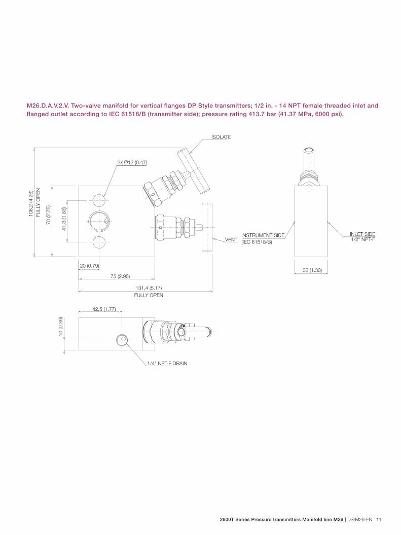
266HSH gauge pressure transmitter on its mounting bracket with M26.P.A.S.2.V. (1/2 in. - 14 NPT male inlet and 1/2 in. - 14 NPT female outlet threaded connection).
266HSH gauge pressure transmitter on its mounting bracket with M26.P.A.S.2.V. (1/2 in. - 14 NPT female inlet and 1/2 in. - 14 NPT male outlet threaded connection).
144 (5.70)
144 (5.70)
324
(12.
75)
226 (8.90)
304
(11.
97)
144 (5.70)
144 (5.67)
226 (8.90)
18 DS/M26-EN | 2600T Series Pressure transmitters Manifold line S26
Model M26Manifold line for 266 pressure transmitters
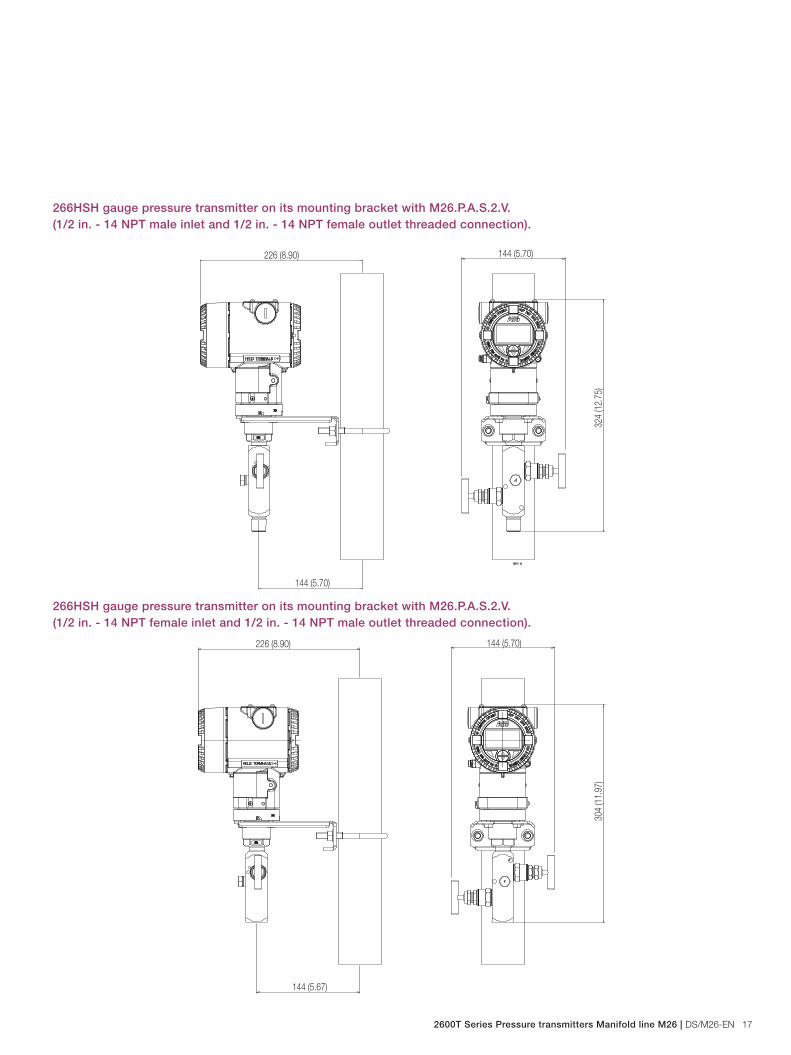
266HSH gauge pressure transmitter on its mounting bracket with M26.P.A.S.2.V. (1/2 in. - 14 NPT male inlet and outlet threaded connection).
266HSH gauge pressure transmitter on its mounting bracket with M26.P.A.S.2.V. (1/2 in. - 14 NPT female inlet and outlet threaded connection).
143 (5.63)
304
(11.
97)
226 (8.90)
144 (5.70)
164 (6.46)
276
(10.
87)
226 (8.90)
144 (5.67)

2600T Series Pressure transmitters Manifold line M26 | DS/M26-EN 19
266PSH differential pressure transmitter on manifold backet with M26.D.A.S.2.V. (1/2 in. - 14 NPT female threaded inlet and flanged outlet according to IEC 61518/B)
266PSH differential pressure transmitter (vertical flanges) on manifold backet with M26.D.A.V.2.V. (1/2 in. - 14 NPT female threaded inlet and flanged outlet according to IEC 61518/B)
94 (37)42 (16.54)33
6 (1
32.2
8)
87 (34.25)102 (40.16)
45 (18.9)
117 (46.06)50 (19.68)
291
(114
.57)
222 (87.40)
215 (84.65)

20 DS/M26-EN | 2600T Series Pressure transmitters Manifold line S26
Model M26Manifold line for 266 pressure transmitters
266DSH differential pressure transmitter on manifold backet with M26.D.A.S.3.V. (1/2 in. - 14 NPT female threaded inlet and flanged outlet according to IEC 61518/B)
190 (7.48)
336
(13.
23)
87 (3.42)
218 (8.58)
209
(8.2
3)
266DSH differential pressure transmitter on manifold backet with M26.D.A.V.3.V. (1/2 in. - 14 NPT female threaded inlet and flanged outlet according to IEC 61518/B)
229
(9.0
2)
291
(11.
45)
258 (10.16)
144 (5.67)
236 (9.29)

2600T Series Pressure transmitters Manifold line M26 | DS/M26-EN 21
266DSH differential pressure transmitter on manifold backet with M26.D.A.S.5.V. (1/2 in. - 14 NPT female threaded inlet and flanged outlet according to IEC 61518/B)
266DSH differential pressure transmitter on manifold backet with M26.D.A.V.5.V. (1/2 in. - 14 NPT female threaded inlet and flanged outlet according to IEC 61518/B)
336
(13.
23)
268 (9.37)
209
(8.2
3)
189 (7.44)
87 (3.43)
236 (9.29)
144 (5.67)
229
(9.0
2)
263 (10.35)
291
(11.
46)

22 DS/M26-EN | 2600T Series Pressure transmitters Manifold line S26
Model M26Manifold line for 266 pressure transmitters
Ordering information
BASIC ORDERING INFORMATION model M26 manifold Select one character or set of characters from each category and specify complete catalog number.Refer to additional ordering information and specify one or more codes for each transmitter if additional options are required.BASE MODEL - 1st to 3rd characters M 2 6 X X X X X X X X X X
Manifold model for 266 Pressure Transmitters
Design - 4th character
Manifold for DP Style transmitters D
Manifold for P Style transmitters P
Revision - 5th character
Revision A A
Body configuration - 6th character
Standard construction S
For vertical-flange transmitter (Note 1) V
Valves - 7th character
Two-valve manifold 2
Three-valve manifold (Note 1) 3
Five-valve manifold (Note 1) 5
Valve Type - 8th character
Standard V
Material (wetted parts) - 9th character
AISI 316L ss NACE S
Hastelloy C276 NACE H
Monel 400 M
Inconel 625 N
Packing material - 10th character
PTFE P
Gasket material (wetted parts) - 11th character
None (Note 2) N
PTFE (Note 1) P
Manifold process connection (INLET)- 12th character
Threaded 1/2 in. - 14 NPT-female F
Threaded 1/2 in. - 14 NPT-male (Note 2) M
Manifold transmitter connection (OUTLET)- 13th character
Flanged outlet according to IEC61518/B (Note 1) 1
Threaded 1/2 in. - 14 NPT-female (Note 2) F
Threaded 1/2 in. - 14 NPT-male (Note 2) M

2600T Series Pressure transmitters Manifold line M26 | DS/M26-EN 23
M26 X X X X X X X X X X X X X X X X X
Rating - 14th character
413.7 bar (41.37 MPa, 6000 psi) (Note 1) 6
690 bar (69 MPa, 10000 psi) (Note 2) 1
Transmitter fixing bolts - 15th characters
None (Note 2) N
Carbon Steel (Note 1) C
Stainless Steel NACE compliant (Note 1) S
Bracket kit - 16th character
None N
Carbon Steel bracket kit for pipe mounting (Notes 1, 3) C
Stainless Steel bracket kit for pipe mounting (Notes 1, 4) S
Material traceability - 17th character
Inspection certificate EN 10204–3.1 of manifold body only 1
Inspection certificate EN 10204–3.1 of process wetted parts 2
Note 1: Not available with design code PNote 2: Not available with design code DNote 3: Not available with bolts code SNote 4: Not available with bolts code C
Manifold made in Italy by SAMI Instruments Srl
Standard delivery items (can be differently specified by ordering code)– PTFE gaskets for transmitter connection (for flanged models)– 1 or 2 Plugs 1/4“ NPT-M (according to the selected manifold model)– Carbon Steel bolts– Certificate of compliance with the order EN10204-2.1– Inspection certificate EN 10204-3.1 of manifold body only.
NACE CONFORMITY IS ACCORDING TO RECCOMENTATIONS PER MR0175 2003 / ISO 15156-3 FOR AISI 316L, HASTELLOY C-276, INCONEL 625 AND MONEL 400

DS
/M26
-EN
11.
2011
Contact us
NoteWe reserve the right to make technical changes or modify the contents of this document without prior notice. With regard to purchase orders, the agreedparticulars shall prevail. ABB does not accept any responsibility whatsoever for potential errors or possible lack of information in this document.
We reserve all rights in this document and in the subject matter and illustrations contained therein. Any reproduction, disclosure to third parties or utilization of its contents - in whole or in parts – is forbidden without prior written consent of ABB.
Copyright© 2010 ABBAll rights reserved
3KXP7200007R1001
Hastelloy C-276TM is a Cabot Corporation trademarkMonel 400TM is an International Nickel Co. trademark
ABB Ltd.Process AutomationHoward Road, St. NeotsCambridgeshire, PE19 8EUUKTel: +44 (0)1480 475321Fax: +44 (0)1480 217948
ABB Inc.Process Automation125 E. County Line RoadWarminster, PA 18974USA Tel: +1 215 674 6000Fax: +1 215 674 7183
ABB Automation Products GmbHProcess AutomationSchillerstr. 7232425 MindenGermany Tel: +49 551 905-534Fax: +49 551 905-555
ABB S.p.A.Process AutomationVia Statale 11322016 Lenno (CO),ItalyTel: +39 0344 58111Fax: +39 0344 56278
www.abb.com