MANHATTAN EEEEEmmEEEmmmE*uhhhhhhuuuuu;1, · The mechanisms for data manipulation in a DDBMS can be...
40
A-AL03 113 KANSAS STATE NV MANHATTAN DEPT OF COMPUTER SCIENCE F/6 9/2 RESEARCH IN FUNCTIONALLY DISTRIBUTED COM4PUTER SYSTEMS DEVELOPE--ETC(U) DEC 76 P S FISHER, F J MARYANSKI DAA$29-76-0108 R. SlEN EEEEEmmEEEmmmE *uhhhhhhuuuuu;1,
Transcript of MANHATTAN EEEEEmmEEEmmmE*uhhhhhhuuuuu;1, · The mechanisms for data manipulation in a DDBMS can be...

A-AL03 113 KANSAS STATE NV MANHATTAN DEPT OF COMPUTER SCIENCE F/6 9/2RESEARCH IN FUNCTIONALLY DISTRIBUTED COM4PUTER SYSTEMS DEVELOPE--ETC(U)DEC 76 P S FISHER, F J MARYANSKI DAA$29-76-0108
R. SlEN
EEEEEmmEEEmmmE*uhhhhhhuuuuu;1,

'LEVEL " __
AIRMICS Army Institute tor Research in 313 Calculator Bldg.Management Information and GA Institute of TechnologyComputer Science Atlanta, GA 30332
Technical Report
RESEARCH IN FUNCTIONALLY-DISTRIBUTED COMPUTER
SYSTEMS DEVELOPMENT
Kansas State University
Virgil Wallentine
Principal Investigator T1CELECTE
SAUG 20 1981
Approved for public release; distribution unlimited
VOLUME VII
A USER--TRANSPARENT MECHANISM FOR THEDISTRIBUTION OF A CODASYLkDATA BASE MANAGEMENT SYSTEM
U.S. ARMY COMPUTER SYSTEMS COMMAND FT BELVOIR, VA 22060
I ' - " -"7I'
0.j
*SECUR,-iY CLASSIFICATION OF THIS PAGE mn n Fnteredj
REPORT DOCUMENTATION PAGE BEFORE COMPLETING F~ORM
(LOR .. .;$IO N. rIET CTAOGNUBE
~I4 MOITRIN AENC NME ADRES(I dffeen trt, Cotrfli ffie) 1. SECU F PRIT CLSS PRO D l Ver
kF 1. , 2O6''A.Bvir VAER-TRAN5P. DECLASSIFICATIONR DOWNGRADING
1.DSBUION ST ATMN (ofSY thi Iteri
17. OITRIUTON TA EME T of heAbtA e BAEte d MAN GE EN Blc §0, YSifeeT fEM ,Rp
IC~rC SUPPLRMENTARYBEOTE)
Department of thper pSitince ness eintd yohratoie
U.NYWS r Reo earh Ofie fce'- neeceye11d1tf7b6loknubr
14. MONTRC G AGNt CY NAM &e e Ad Re SSI diferen fro nt rolliby b O fcmer) 1.SC RT LS.CtCi eot
(~ ~ U Arm Copue Sy473m CDTO F O 55ommand UnclassifiedAttCnI: CLSATaICSICATION DISPO WNGRADIN
Ft_____r V 20 SCHEDL16.ITIUIO1TTM N ofti sor

UNC 1.AS S§H±Da.SECURITY CL AAiVICATION OF TIS pACE(When Data Cntared)
-ABSTRACT-
'A software organization is presented to provide for
data definition and manipulation in a distributed data basemanagement system. With the mechanism for distributing the
data base proposed here, the physical location of the data
is transparent to the user program. A Device Media ControlLanguage is specified for the assignment of control of andaccess to a data base area to a set of processors.Procedures for reassignment of the control and accessfunctions as well as the transfer of data between processors
are provided. The basic hardware and software requirementstc.r a computer network capable of supporting a distributeddata base management system are discussed along with aspecification of the software required for a processor in adistributed data base network.
U14CLASSIV IED
tel'
A User-Transparent Mechanism
for the Distribution of
a CODASYL Data Base Management
System
TR CS 76-22
December, 1976
Fred J. MaryanskiPaul S. Fisher
Virgil E. Wallentine
Accession For
NTIS GRA&IDTIC TAB ElUannouncedJuSti icatlo-
By .Distri-butlon/
Avallability CodesAvail. and/o-
Dist Special
The work reported herein is supported by the U.S. ArmyResearch Office Grant No. DAAD-29-76-G-0108.
__ _ _ _ _ __ _ _I i

I!
Abstract
A software organization is presented to provide for data definition
and manipulation in a distributed data base management system. With the
mechanism for distributing the data base proposed here, the physical
location of the data is transparent to the user program. A Device
Media Control Language is specified for the assignment of control of
and access to a data base area to a set of processors. Procedures for
reassignment of the control and access functions as well as the transfer
of data between processors are provided. The basic hardware and soft-
wire requirements for a computer network capable of supporting a distributed
data base management system are discussed along with a specification of
thu software required for a processor in a distributed data base network.
4 Ait
I

I. Introduction
This paper presents a software organization for a distributed data
base management system (DDBMS). A DDBMS is a data base management system
that resides on a network of computers. The processors in the network may
perform any combination of the three following functions.
a. Front-end = act as user interface, receive input, transmit output.
b. Host = execute the application program.
c. Back-end = control data base access through execution of data
base system software.
The DDBMS software structure presented in this paper reflects the
CODASYL-type data base systems [1,2]. The basic software distribution and
s, veral possible hardware configurations for DDBMS systems are discussed
In Reference [3]. The emphasis of this paper is to specify the software
fuijctions that are required in order to provide for proper data definition
and manipulation in a DDBMS.
One of the principle tenets of the proposed DDBMS organization is that
'Ac physical distribution of the data be transparent to the user. This
imp~ies that at the application program level, both the program and the
z, r are unconcerned with the precise physical location of the data or of
thi processor that is accessing the data. In addition, the DDBMS must have
rapaoility of moving data among secondary storage devices and DBMS
finctions among processors. However, the user may stipulate that units
-f dLita be physically close. Additionally, it is necessary for the system
.-.(ftw.re to be portable in order for an application program to execute on
:yi,' host machine and access data through any back-end processor. This
ability, to request relocating of tasks and data, is partially within the
x .... ... ... .._

2
DDBMS, but as with all application software, allocation of resources is
dependent on the network operating system (NOS) upon which the DDBMS is
constructed (in this paper it is supported by an NOS subsystem called
Network Resource Control (NRC)). Information on the characteristics of
a network operating system capable of supporting a DDBMS can be obtained
in Reference (4).
The remaining sections of this paper contain a set of proposed mech-
anisms for defining and utilizing data in a DDBMS which has the capabilities
described in the preceding paragraphs.
A . .. ,~

It. Data Definition
In a CODASYL-type DBMS the description of the data is carried out
in three steps. Initially, the schema Data Description Language (DDL) is
used to describe the logical organization and format of the data base.
That portion of the data base accessible to a particular program is defined
by means of ;he sub-schema DDL. The schema and sub-schema are both logical
descriptions of the data. The logical to physical mapping is accomplished
through use of the Device Media Control Language (DMCL). It is important to
note that the CODASYL committee contidered the DMCL as an implementation-
dependent feature of a DBMS and consequently, has not specified a DMCL. It
is through the DMCL that the distribution of the data base is accomplished.
In the definition of a distributed data base (as in the case of a
central system) the existence or lac): of physical proximity of records is
determined by their placement in areas. Areas serve as the atomic data unit
in terms of the distribution of the data base. The DMCL is used to associate
areas with both logical back-end processors and secondary storage devices.
This information is compiled from the DHCL and stored in the Area Logical
Location (ALL) Table. The system may transport areas between physical
devices. Such actions would remain transparent to the DBMS application
programs provided the ALL tables and the tables of contents of the actual
disk cartridges indicating, respectively, the physical location of the area
and the contents of the cartridge ate properly updated.
By restricting the effects of transparency to the description of the
areas in the DMCL, both the schema and sub-schema DDL's remain unchanged In
a DDB1S. The syntax of a DMCL for a dLstributEd CODASYL-type data base
system is shown in Figure 1.
The PACE NLMBER and SIZE sentences in the Area Section are used to
.9i

. SCHEMA SECTION
DMCL FOR SCHEMA. B:. ,
SUBSCHEMA SECTION
SUBSCHEMA IS SUBSCHEMANAME.
AREA SECTION
AREA IS ThAtM.
NUMBER OF PAGES IS INEGER1.
PAGE SIZE IS INTEGER2.
BACKEND IS PROCESSORNAME,
DEVICE IS tv.c.FAtE.,
(TYPE IS IDENTIFIER.)
HOSTS ARE (PROCESSORNAME-S).
FIGURE 1
DMCL SYNTAX

describe the size of the area. The BACKEND sentence provides a logical
name for the processor which controls access to the area. The DEVICE
sentence provides a logical name and physical type for the device upon
which the area is to be stored. A physical type can include disk, tape,
cassette,.floppy disk, or any other mass storage medium. The physical
device type name can be dependent upon the back-end processor or (preferrably)
follow a standard network convention. The HOSTS sentence logically names
processors which may contain application programs that access the data in
the area being described.
The HOSTS sentence provides an additional measure of security to the
DDBMS. The data base administrator can specify if the area may be accessed
globally or restricted to a certain application system. It is important
to note that the HOSTS are identified logically in the DMCL. The HOSTS
sentences are specifications as to which application function may access
the data in an area. This application function may reside on several
distinct processors and may be moved among processors by the network oper-
ating system. However, unless the data base administrator assigns a logical
function name that appears in the HOSTS sentence of an area to a physical
processor, no program executing on that processor may access data in that area.
The product of a DMCL compilation is an ALL Table whose entry format
is depicted in Figure 2. An ALL Table is maintained for each schema. Within
the table the information is grouped by area. The area information is obtained
directly from the DMCL code.
It should be noted that processors and devices are identified logically
in the ALL Table.. This allows areas and tasks to change their physical
location in a manner transparent to the DBMS. The logical-to-physical mapping
for processors is maintained in the network operating system nucleus on each
machine. The companion mapping for devices is maintained locally at each

-j
CLi
C/) CiL
-JJ
UI-
LU 0LI-
LNJ >- i~
L.O C/) I-- I-
o LI) wLL.. P c
U--c
z
(-j3
C/l)
---------

74
network node. Figure 3 illustrates the ALL Table and logical-to-physical
map for a sample distributed data base.
III. Data Manipulation in Distributed Data Access
The mechanisms for data manipulation in a DDBMS can be presented by
considering the steps that are required for a user program to access data
on a device connected to another processor.
Before an application program can access data in an area, it must first
issue a READY statement (1] for that area. The data base system obtains the
logical back-end processor and device name from the ALL Table entry of the
area named in the READY statement. The physical processor name is obtained
from Logical-to-Physical Processor Map maintained by the network operating
system. A message is then sent to the back-end processor requesting that
the area be made available to the application program and that a task be
created for that sub-schema (if one does not already exist). The general
format of the messages sent in the DDBMIS is given in Figure 4. If the device
containing the area is online at the back-end processor and all integrity
and security requirements are satisfied, the back-end transmits a message to
the host processor and the application program may begin to utilize the data
in that area.
There are several situations which can hinder the completion of the
READY statement. FLrst, we treat the problem of the device(s) containing
the area not being online. In this case, a message is transmitted to the
operator of the back-end processor, requesting mounting of the proper disk
pack. The pack is identified by the name obtained from the ALL Table. When
the pack is placed online, the data base system automatically verifies its
name against that requested by the application to detect any possible oper-
ator errors. Each data base contains a header which indicates the logical

DATA BASE (PK PROCESSOR, A K -AREA)
ALL TABLE (PARTIAL)
AREA BACKEND HOSTS PTR
Ao B0Ai J B ALL -- 0 H2JA3 B1A-2BA3 B
LPP W LOG ICAL NAME PHYSICAL ID
B0 P0B1 P1B2 P1B3 P2
NJ P1N2 P0
FIGURE 3 SAMPLE-DiSTRIBUTED DATA BASE

1' 9SEND MESSAGE (TOID, MESSAGE, SIZE, EVTID)WHERE
TOID IS THE SYMBOLIC NAME OF THE TASK WHECHIS TO RECEIVE THE MESSAGE.
MESSAGE SPECIFIES THE BEGINNING ADDRESS OF THEMESSAGE TO BE SENT.
SIZE SPECIFIES THE SIZE OF THE MESSAGE TO BESENT,I EVTID IS AN EVENT UNIQUELY IDENTIFIED WITH THISMESSAGE.
RECEIVE MESSAGE (FROMID, MESSAGE, EVTID, SIZE)WHERE
FROMID IDENTIFIES THE NAME OF A TASK FROM WHICHA MESSAGE IS TO BE RECEIVED.
EVTID, SIZE, AND MESSAGE ARE AS BEFORE.
WAIT (EVT_ID)WHERE
EVTID IS AN EVENT WHICH IS SET TO "HAPPENED"
WHEN ITS ASSOCIATED OPERATION IS COMPLETE. IT ALLOWS
PROCESSES TO SUSPEND AWAITING PARTICULAR OPERATION.
SEND_COMMAND (TOID, COflMAMD, EVT_If)
ACCEPTCOMMAND (FROMID, COMMAMD, EVTID)WHERE COMMAND IS A FIXED SIZE (SMALL) MESSAGE
CONNECT (TOID, COMMAND)
DISCONNECT (FROMID, TYPE)WHERE
TIMMEDIATE, ABOUT ALL ACTIVE MESSAGESTYPE QUIESCE, ALLOW ACTIVE MESSAGES TO BE
SENT BUT NO MORE INITIATED
FIGURE 4CONCEPTUAL MESSAGE FORMATS

107
(back-end) processors capable of accessing its data. This feature is included
for security purposes. If the processor names correspond, the back-end pro-
cessor will notify the host processor that the area is available for data
manipulation.
Another problem occurs when there is no entry in the Logical-to-Physical
Processor Map for the back-end processor name obtained from the ALL Table.
In this case the host processor must obtain from the Data Dictionary a
list'of processors that have the potential of operating under that logical
back-end name. Messages requesting, that a back-end processor assume the
functions associated with that logical name are then transmitted to the proces-
sors in that list. Once a back-end is identified, a request is made to
mount the appropriate device for the area being READYed. If no machine can
assume the requested logical processor role, the application program on the
host processor is terminated.When a processor assumes a back-end function, a task must be created
in that processor to handle the data base requests for that area. All other
processors in the network then are notified of the new logical name for the
processor.
Once the area has been READYed, the user program on the host machine
may issue D[L commands to reference the data. 'The area name for any
record to be accessed by the DML commands is available in the sub-schema
which is attached to the application process during process initiation.
Using the area name, the physical location of the record in the network can
be determined from the ALL Table, the host machine then transmits a message
to the appropriate back-end processor which performs the DBMS operation and
transmits the results back to the host processor via the message system.
In a CODASYL-type DBMS, it is possible that an operation on a record in
one area may result in the need for operations on records in other areas
_ J

11
(for example, the removal of an owner record and thus all its members from
the data base). In such situations, the back-end processor controlling the
operation determines the back-end processor name for the effected are*
from the ALL Table. If the processor names are different, a message
indicating the necessary data base action must be sent to the back-end
processor of the area. This procedure could reoccur several times before
nompletion of the original DBIS operation, depending upon the complexity
and distribution of the data base. When the original back-end processor
has received completion messages from all of the secondary back-end
machines, it then transmits a message with the appropriate data and status
information to the host computer.
IV. Task and Data Movement
A. Conceptual Aspects
In a DDBMS, it may be desirable for reasons of efficiency or security
to change the physical location of a data base management task or data
area. Movement of data can occur either logically by a programmed (file)
transfer of an area between storage devices or physically by an operator
moving a storage device from one computer to another. Tasks are moved in
& DDBHS by making use of features provided in a network operating system.
The case of logical data movement will be cobsidered first. When an
area is moved between devices controlled by the same back-end processor, the
device name must be modified in the ALL Table of that back-end processor
and the header record on the storage media must be updated. Movement
between devices attached to different processors requires updating the ALL
Tables for all back-end processors that control any portion of the sub-schemas
containing the transported areas. It can be seen from the description of data
manipulation in Section III that if the ALL Tables are properly updated, there
will be no effect on either the user program on the host or the data base
4
12
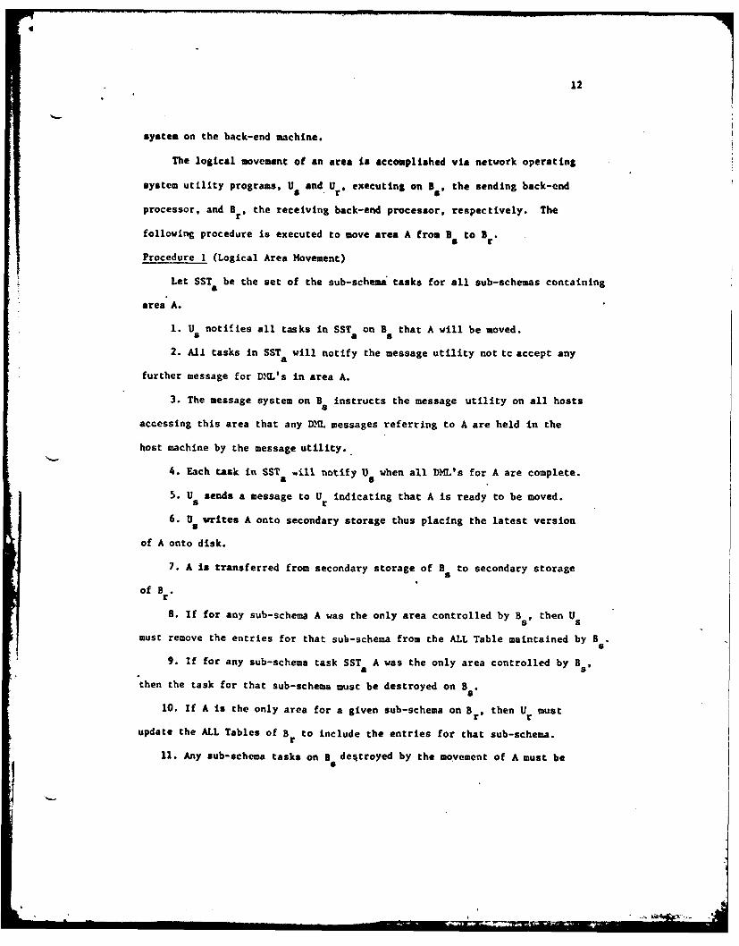
system on the back-end machine.
The logical movement of an area is accomplished via network operating
system utility programs, U and. Ur. executing on B., the sending back-end
processor, and Br, the receiving back-end processor, respectively. The
following procedure is executed to move area A from B to B .
Procedure I (Logical Area Hovement)
Let SST be the set of the sub-schema: tasks for all sub-schemas containinga
area A.
1. U notifies all tasks in SST on B that A will be moved.8 a 5
2. Al1 tasks in SST will notify the message utility not tc accept anya
further message for DML's in area A.
3. The message system on B instructs the message utility on all hosts
accessing this area that any DXL messages referring to A are held in the
host machine by the message utility..
4. Each task in SST aill notify U when all DML's for A are complete.a •
5. U sends a message to U indicating that A is ready to be moved.sr
6. 0 8writes A onto secondary storage thus placing the latest version
of A onto disk.
7. A is transferred from secondary storage of B to secondary storage5
of B .r
8. If for any sub-schema A was the only area controlled by B, then Us
must remove the entries for that sub-schema from the ALL Table maintained by Bs.s
9. If for any sub-schema task SST A was the only area controlled by Bs,
aathen the task for that sub-schema must be destroyed on Ba
10. If A is the only area for a given sub-schema on Br, then Ur must
update the ALL Tables of B to include the entries for that sub-schema.r11. Any sub-schema tasks on B destroyed by the movement of A must be
5

13
created (if not already present) on B.
12. If by receiving A, Br is now assuming a new logical back-end function,
then the L-P-P Map on B must be updated.
13. If by sending A to B8, B no longer retains that particular back-end
function, then the L-P-P Map on B must be updated.
14. Update all L-P-P Maps in the network if necessary.
15. The sub-schema tasks in SST on B obtain the list of hosts for A
ftom the ALL Table.
16. The sub-schema tasks in SST notify the message utilities which area.
queueing requests from their corresponding host tasks that they will now
accept DML messages for A.
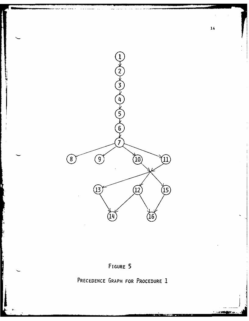
Figure 5 gives a precedence graph for Algorithm 1. The interaction
of the utility tasks and system software resulting from the execution of
Procedure 1 is illustrated in Figure 6. Only the software directly involved
in logical area movement is pictur2d in Figure 6.
The situation in which a physical device is moved is more complex
than logical movement. The most difficult situation occurs if the pack
(or any other type of storage device) is active on a back-end processor and
the operator indicates to the system the desire to remove that pack from
online status. The data base management software'on the back-end processor
must complete all requests to areas on that pack and inform the effected
hosts to hold all new requests for those areas. The operator may then
disengage the pack and remount it on a new machine. When the pack is
mounted on the new machine, the procedure outlined in Section III for bringing
ap a new pack in the DDBMS can be followed. It is important to note that in
order for a processor to be eligible to receive the transferred pack, it must
be read and write compatible with the source processor as well as have the
necessary logical processor function assigned to it.
14
2
3
5
6
13121
14 16
FIGURE 5
PRECEDENCE GRAPH FOR PROCEDURE 1
q J

15
APPLICATION TASK
PHOST L-P/P MAPI---MESSAGE UTILITY
L-P-P BR LPP a-IE
MAP MAE
- ,
isU S A G U R
G U GUo o ® T E ET
I 4I L L.I IIIT T__ _
Y VIALL
TABLE i TAiSSTA LL-- SST T
(SUB-SCHEMA (SUB-SCHEMA6 TASKS) TASKS)
I /( /\
FIGURE 6
LOGICAL AREA MOVEMENT

16
In order to allow the DDBXS to stop processing a pack prior to its
movement, the list of active areas on the pack is determined from the Device
Header List that is maintained by the back-end processor. For each area,
the list of logical host names is obtained from the ALL Table. The back-
end processor then accesses its Logical-to-Physical Processor Map to deter-
mine the host computers which must be sent the messages indicating an area
transfer.
The back-end data base software which controls the mounting of a new
pack must be cognizant of requirements stating that in order for a given
pack to be accessed some other pack (or packs) must also be attached to the
same processor. Such constraints could occur in the cases of multi-device
areas or for security or efficiency reasons.
The physical movement of a data base pack between back-end processors
results from carrying out the steps of Procedure 2. A pack shutdown utility
Ud is first executed on the sending back-end processor B . A pack mount
utilityU 0, is then executed on Br , the receiving back-end processor.
Procedure 2 (Physical Pack Movement)
1. The B operator activates pack shutdown utility, Ud.
2. U initiates steps 1 - 4,6,8-9, and 13 of Procedure 1 for each aread
on the pack.
3. U notifies the B operator that the pack may be moved.ds
4. The B operator removes the pack.5
5. Br operator mounts the pack.
6. Br operator activates pack mount utility, U a
7. U initiates steps 10-12 and 14-16 of Procedure I for each area on the pack.
There are two types of task movement in a DDBNS; the transferring of an
application program between processors, and the interprocessor movement of
back-end software. Both cases can be considered as processor function

17
reassignment.
In the case of host function movement the only action required is a
change in the Logical-to-Physical Processor Hap in the network operating
system. The redefinition of the ability for appropriate processors to
access an area can also be accomplished by executing the DMCL compiler with
a modified HOSTS paragraph.
The back-end functions may only be transferred if the receiving pro-
cessor is linked to the storage device(s) containing the area. The
mechanisms for accomplishing the transfer are identical to the host
situation. Either the network operating system Logical-to-Physical Pro-
cessor Hap or the DMCL BACK-END sentence can be amended.
Thus as in the case of data movement, tasks (processor functions)
can be moved in a DDBMS with minimal overhead and with no alteration
required to user or DMIS software.* This statement is predicated upon the
portability of the data base zystem software. Given the state of the
industry, movement must be restricted to homogeneous machines for the
present.
One important fact concerning the relationship between logical and
physical names for physical entities (processors, devices) is that the
mapping can be one-to-one, many-to-many, one-tb-many, or many-to-one. A
one-to-many mapping indicates a multi-processor configuration or an area
spread across several devices. A processor or storage device can be
identified by several logical names, thus producing the many-to-one rela-
tionship. The many-to-many mapping is a merger of the two previously men-
tioned situations. The flexibility of the logical to physical mapping
provides the data base administrator with considerable latitude in the
distribution of the data base.
U l I I L , , . .' ... . .* -' _ : * - ,• ,

18
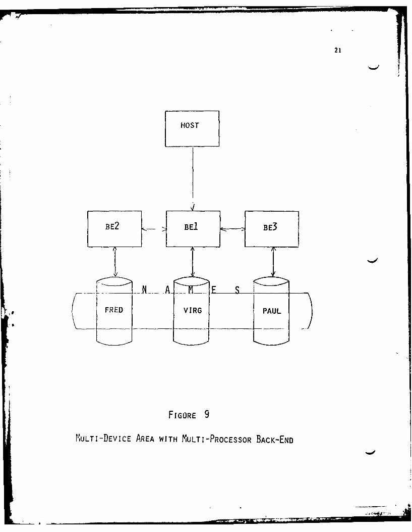
Figure 7 depicts a one-to-many device mapping. The area NAMES is spread
over three physical devices. The record occurrences, FRED, V IRG, and PAUL,
all reside on separate disk packs controlled by the same back-end processor.
The multi-device area concept is found in many commercially available data
base management systems.
A one-to-many processor mapping implies the existence of a multi-processor
back-end. A multi-processor back-end consists of several processors joined
via a memory-to-memory connection. Each processor has access to the areas
controlled by the back-end function shared by the processors. If a processor
in a multi-processor back-end configuration does not have a direct physical
connection, it requests that a processor having such a link perform the I/O
transfers. With a shared memory interprocessor connection, such requests
are performed at machine memory speeds. Figure 8 illustrates a multi-
processor back-end configuration. The concept of multi-processor back-end
machines is discussed by Lowenthal in Reference [5]. Figure 9 portrays a
many-to-many mapping which is realized by combining the configurations
shown in the two previous figures.
For a given distributed data base system, the range of a multi-processor
back-end configuration is limited by the network topology. A generalized
network such as MIMICS [4) is composed of a collection of machine clusters
joined together. Within each cluster several processor nodes linked via
high speed memory connections, (5 -10 Megabyte/sec). Figure 10 shows the
general topology of the HIMICS network.
The following rules apply to multi-processor back-ends:
1. The processors comprising a multi-processor back-end must be
members of the same cluster.
2. Areas ay not span clusters. As shown in Figures 8 thtulO,it is
VI.

19
HOST
BACK-END
FRED VIRG PAUL
FIGURE 7
MULTI-DEVICE AREA

20
HO0ST
BE2 BEl BE3
N ESWIVES CH
FRED KARENJENVIRG 7DEE TODDPAUL RUTH HOWARD
4myQRA I GMA7E
FIGURE 8
MULTI -PROCESSOR BACK-END
21
HOST
V¢BE2 -- BE1 ---- BE3
, FRED VIRG
FIGORE 9
MULTI-DEVICE AREA WITH MULTI-PROCESSOR BACK-END
L A2-

22
CLUSTER I
CLU.S TER K
CLUSTER J
FIGURE 10
GENERAL TOPOLOGY OF MIMICS

23
not necessary for each node in a multi-processor back-end cluster to have
a communication link to a host computer (or a cluster of host computers).
The node with the communication link (BEI in Figures 8 and 9, for example)
functions as the master back-end for that multi-processor back-end configu-
ration. The master handles the communication operations and parcels out
the DUL commands to be executed by the individual back-end processors.
An analysis of the performance, security integrity, and economic
benefits of the multi-processor back-end concept has been performed by
Lowenthal [5].
B. The Inter-Process Communication System (IPCS) of MIMICS
Movement of (areas of) data In a DDBMS is accomplished via some inter-
process communication (message) utility which has the following functions:
1) It makes the topology of the network transparent to the application
program;
2) it makes data distribution transparent to the application program;
3) it synchronizes the tasks which exchange data to insure no data is
lost, garbled, or pilfered;
4) it manages the names of network tasks;
5) and finally, it transmits data and commands between tasks (appli-
cation program and DBMS tasks, for example). The concepts of the IPCS
commands available to a task level are provided in Figure 4.
The IPCS of'HIMICS is connection-based. That is, the general scenario
of IPCS usage by a task is as follows:
1. CONS.ECT (,.--
2. Exchange data using SEND and RECEIVE; exchange commands using
SEND COOAD and ACCEPT CO14AND; and WAIT on a particular function
completion when necessary

24
3. DISCONNECT(, ,---)
The CONECT/DISCONNECT functions establish and destroy data/command paths
between tasks. The SEND/RECEIVE functions exchange data. The IPCS syn-
chronizes the message SEND's from the source task and the RECEIVE's from
the destination task to assure proper space is allocated for the message.
The SEND_/ACCEPT_COW1AND functions allow commands to be exchanged between
user tasks without prior data space allocation necessary. This permits
user' tasks to exchange simple commands to establish a protocol for exchang-
ing messages. It also permits priority traffic for error or control
information to be exchanged. This is the mechanism used for movement of
areas in a transparent manner. Since all of the above SEND's and RECEIVE's
do not force the task to stop execution until completion (to provide over-
lap of execution and data exchange), the task may choose to WAIT until a later
tiu.e on a particular SEND or RECEIVE (event).
The general structure of the IPCS is shown in Figure 11. The appli-
cation program conceptually exchanges DML's and data/status with the DBHS
task. The User Envelope transmits these elements across a network as
data and commands. The User Envelope thus maps source and destination
tasks onto source and destination logical processors and then onto physical
processors via the L-P-P map and the ALL table. Thus the System Envelope
has the capacity to re-route DM.L's and data/status via a new mapping. The
Message System merely does the moveient of data between tasks which have
established a connection.
Figure 12 illustrates the method by which the movement of an area between
two back-end machines can be achieved in a manner transparent to an applica-
tion program. It is assumed the application program task (APT) and the DBMS
have an established connection. The general procedure, from the view of the
message system, to move an area is as follows:

25
PPLIATIO- - DML STATEMENTS
PROGRAM - - STATUS/DATA__ DBMS
-MESSAGES
USER - -c -NTC'oW USERUSE P RO0TOCEOL CSYVN C HR ON JIM;_ENVELOPE ~ TO-ADCMAD
M1 E S S A 1 E
COMMANDS
FIGURE 11
LEVELS OF MIMICS PROTOCOL

V C%4LU4Z SWu
-~~a c0iI-- c
Li9= 6% in
-Jv
w c;
w L
>2 0 0
Lu 0. LLU ~L no si0
zO ~ 4
0 0
MiL 0 0
u z -w U)0Z 1. z 0U
, WCO j Z CO CLL~ E0 LU V)
4O u 0 ~JUJ.4c 4u C4W 4 ~ ft
w w W- UJ~ x
U) 2,
w '/> IQ0

27
1) The User Envelopes exchange the desire (initiated from either
end) to DISCONnECT after a certain sequence of messages is complete.
2) Each does a DISCONNECT ( QUIESCE). (These are synchronized by
the Message System.)
3) The AREA is transferred by a file transfer protocol 161 via a
connection between tasks U and U . (See Figure 6.)s r
4) The User Envelopes on the Host and Back-End 2 (BE2) then connect
as follows:
The Host User Envelope requests a network task name for DBMS task
on BE2 from the Network Resource Controller (NRC) on the Host. The
NRC's of all processors are fully connected. Thus this request is
made of the NRC on BE2. It responds with the task name. The User
Envelope then connects to the BE2 User Envelope and D4L's and data/
status flow between the Host APT and the BE2 DBMS task.
It is important to note that NRC must access only the L-P-P map. It should
be clear from Figure 12 that the Host APT does not participate in the move-
ment or knowledge of the movement of the AREA other than by observing some
performance change.
V. Structure of Host and Back-End Software
A host computer in a DDBMS musc contain software to execute application
programs, to select the proper back-end for data base functions, and to
comunicate with the back-end processor. In order to meet these ends, a
host must have a software organization similar to that depicted in Figure
13. The Logical-to-Physical Processor Map (L-P-P Map) is simply an array
of physical Identifiers indexed by logical names. As mentioned in prior
sections, this map is used in the selection of the back-end processor.
The Inter-Process Comaunicacion System (IPCS) 141 serves as a generalized
--tocmunication system for the data base network.

28
USER PROGRAM K
USER WORKING SYSTEM DBMS 0----AREA ,_ LOCATONS . INTERFACE P
E
USER PROGRAM 1 T
USER WORKING SYSTEMS IAREA LOCATIONS INTERFACE NIG
SUB- SUB-SCHEMA SCHEMA S
1 M y
DBMS T
AREA LOGICAL ILOGICAL TO E
LOCATION TABLES ,SYSTEM LOCATIONS PHYSICAL PROC-FSSQ)R MAP
IPCS
(INTER-PROCESSOR COMMUNICATION SYSTEM)
FIGURE 13
HOST SOFTWARE ORGANIZATION

"7 - - - ...
29
A back-end processor must hold the sub-schema and DMCL Tables for
each area in its domain. Due to the possibility of multiple back-end
participation in DML execution, each back-end processor must contain
complete ALL Tables for all sub-schemascontaining areas managed by that
machine. The back-end must also contain the Logical-to-Physical Processor
Hap in order to determine physical processor identification. As shown
in Figure 14, the back-end software must also include a Device Header
List (b.H. List) which indicates the contents of the secondary storage
units. The Device Header List contains a linked list of areas with each
list headed by a device indicator name.
It is important to note that a single machine may be both a host and
back-end processor. In that situation, the software shown in both Figures
13 and 14 must reside upon that machine. If a processor assumes more than
one logical host or back-end function, the DMCL Tables and sub-schemas for
each logical processor function mist be stored in the memory of the machine.
Figure 15 illustrates the software required on processor P1 of Figure 3.
PI has two back-end functions, B1 and B2, and one host function, H1 ,
associated with it.
VI. The Data Dictionary
Each processor in a DDBMS may require access to any schema, sub-schema,
or ALL Table. Copies of this information are maintained in the data
dictionary. When'a DBMS application task is loaded onto a host processor,
its associated sub-schema and ALL Tables are obtained from the data dic-
tionary. The data dictionary also holds the potential Logical-to-Physical
Processor Map which indicates those processom permitted to assume a particular
logical name. This list is used whenever an application program requests an
orea for which there is no active processor performing that back-end function.
The general structure of a DDBMS data dictionary is illustrated in Figure 16.

30
IPCs 0P
(INTER-PROCESSOR COMMUNICATION SYSTEM) ER
ILOGICAL TO ABUFFERS !PHYSICAL T
PROCESSOR MAPT~I
NDBMS G
ALL TABLE DH. LISTy
SUB- SUB- SSCHEMA SCHEMA T1 IE
__ _EM
DML DMLTASK TASKi J
FIGURE 14
BACK-END SOFTWARE ORGANIZATION
.I• = __ . ... . .. •i "- lr 4-

31
USER PROGRAM K__
UWA SYSTEM LOCATIONS I DBMS INTERFACE0
USER PROGRAM I E
UWA SYSTEM LOCATIONS DBMS INTERFACE R
,NiB-SCHEMA 1(H1) .SUB-SCHEMA M(H)T
DBMS (HOST)
ALL TA LE (INCLUDES ENTRIES SYSTEM LOCATIONS GFOR B1, B2, H1)
SUB-SCHEMA 1(B1) 1 . , . SUB-SCHEMA K(BI) S
SUB-SCHEMA 2) . . . SUB-SCHEMA I(B2) S
D.H. LIST L-P-P MAP Em
DML TASKi I DML TASK J
DBMS (BACK-END)
BUFFERS
IPCS
FIGURE 15
SOFTWARE ORGANIZATION FOR A
PROCESSOR WITH MULTIPLE FUNCTIONS

32
SCHEMA 1
SCHEMA OBJECT MODULE
ALL TABLESCHEMA
, SUB-SCHEMA 1
SUB-SCHEMA OBJECT MODULEENTRYo0
SUB-SCHEMA K
SUB-SCHEMA OBJECT MODULE
SCHEMA 2 ENTRY
S
SCHEMA M ENTRY
POTENTIAL LOGICAL TO PHYSICAL
PROCESSOR MAP
FIGURE 16
DATA DICTIONARY ORGANIZATION
- ' ....... ... ., ",,, i ' ... , i' " I

33
The exact mechanism of implementing the data dictionary can vary with
r the structure of the underlying computer network. The dictionary must reside
on a high speed secondary storage device for rapid access. The data dictionary
is used generally for query with little update. Therefore, multiple copies
of the data dictionary may be maintained for the sake of reliability and more
rapid reference. In certain environments, it may be desirable to partition
the data dictionary into sub-dictionaries which contain information on data
residing in particular sections of the network.
VII. Conclusion
This paper has presented a mechanism for the distrib~lon of a
CODASYL-type data base management syitem in a manner that is transparent
to the application program. The software structure presented herein
presupposes an underlying computer network with the necessary hardware
and software to allow interprocessor communication via a standardized
message system. The basis for distribution in the DDBHS is the ALL Table
which provides information on the location of each data base area.
The mechanisms detailed here provide a DDWIS communication facility
that is relatively easy to realize. However, many of the problems of
distributed data systems, as outlined by Fry and Sibley (7], still
require practical solutions. The dilemmas posed by deadlock, backup.
recovery, and security are extremely complex. Another forwidable stumb-
ling block for distributed data base systems is the general lack of port-
ability and compatbility within both the hardware and software environments.
The system described here could be implemented with moderate effort on
homogeneous networks. For heterogeneous networks, advances in soft-
ware portability and standardized communication protocols are required.
Progress is being made in these areas although it is hampered somewhat
Sy the marketing philosophy of "locking the user in" to a vendor's
-product line.
_J

*jI 34
Bibliography
1. CODASYL COBOL Journal of Development, Dept. of Supply and Services,
Material Data Management Branch, Ottawa, Ontario KIA OS5, (revised
to) June, 1976.
2. CODASYL Data Description Language Journal of Development, Document
C1362:113, U.S. Covernment Printing Office, Washington, D.C., 1973.
3. Maryanski, F.J., et al., "A Minicomputer Based Distributed Data Base
System, Proc. IEEE-XBS Symposium on Trends and Application 1976:
Micro and Mini Systems, May, 1976, pp. 113-118.
4. Wallentine, V.E., "MIMICS-The Capabilities to be Developed", Computer
Science Dept., Kansas State University, Manhattan, KS. 66506, May, 1976.
5. Lowenthal, E.I., "The Backend Computer", MRI Systems Corp., P.O. Box 9968,
Austin, Texas 78766, Apr., 1976.
6. Wallentine, V.E., et al., "Progress Report on Functionally Distributed
Computer Systems Developemnt: Software and Systems Structure" TR CS77-4,
Computer Science Dept., Kansas State University, Manhattan, KS. 66506,
Dec. 1976.
7. Fry, J.P. and Sibley, E.H., "Evolution of Data-Base Management Systems",
Computing Surveys, Vol. 8, No. 1, May, 1976, pp. 7-42.
* *4


![Under Pressure Benchmark for DDBMS Availability · DDBMS: oltDB,V NuoDB and Dbms-X. Categories and Subject Descriptors: H.2 [ Database Management ]: Miscellaneous Keywords: distributed](https://static.fdocuments.net/doc/165x107/5f158479dbe2921f4c616e3f/under-pressure-benchmark-for-ddbms-availability-ddbms-oltdbv-nuodb-and-dbms-x.jpg)