
MAN_GN_PDF_7
30
7.1 7 BRAKE SYSTEM 1BRAKE SYSTEM 7.1Tasks and effects, definitions x Single-circuit brake system Energy supply + Actuating device Transmission device Front axle brake Rear axle brake Dual-circuit brake system Energy supply + Actuating device Transmission device circuit 1 Transmission device circuit 2 Front axle brake Rear axle brake BASIC PRINCIPLES Brake system The brake system of a commercial vehicle has the task of reducing the speed if re- quired, bring the vehicle to a standstill, or keeping it at a standstill. It consists of the following components: Power supply This includes all the parts that provide, control and prepare the energy necessary for braking. Actuating device The components of the actuating device initiate the effect of the brake system and control the braking effect. Transfer device The parts of the transfer device serve to pass on the energy controlled by the actu- ating device. Wheel brakes The wheel brakes transform part of the ki- netic energy of the vehicle into heat (fric- tional heat), thus braking the vehicle. FUNCTION Functional areas of brake systems As a general principle, the brake system of a commercial vehicle is divided into four functional areas: Service brake system This reduces the speed of the vehicle. The service brake is foot-operated by the dri- ver; it must be gradual and stepped. Ser- vice brake are constructed as friction bra- kes and are subject to wear. Secondary brake system The secondary brake system must assu- me the function of the service brake if it fails. It does not have to be an indepen- dent brake system; the second circuit of a dual-circuit brake system is sufficient (➜ page 7.3). Parking brake system This serves to hold the vehicle and secure it against rolling away. Continuous service brake system Continuous service brake systems are de- vices for wear-free conversion of the kine- tic energy of a commercial vehicle into he- at. They are to be regarded as supple- mentary brake systems. They include engine brakes (➜ page 7.19) and retar- ders (➜ page 7.26). Pneumatic brake system Brake systems for commercial vehicles with a permitted total weight of over 7.5 t almost always work with compressed air (at MAN, exclusively so). In the case of medium-weight and heavy commercial vehicles, the foot power of the driver is not sufficient to provide the re- quired braking effect. This is why so- called pneumatic power brake systems are used. These systems use com- pressed air as stored energy to operate the service brake system. The pressurised air directly affects the diaphragm or piston cylinder, which in turn create a braking ef- fect through friction in the corresponding wheel brake. Brake circuit A distinction is made between brake sys- tems with one or two brake circuits. The latter have two independent transfer de- vices, which means that if circuit 1 fails the brake system still works via circuit 2 (➜ Fig.).
-
Upload
adrian-a-upd -
Category
Documents
-
view
3 -
download
0
description
man
Transcript of MAN_GN_PDF_7

7.1
7
BR
AK
E S
YS
TE
M
1BR
AK
E S
YS
TEM
7.1T
asks
and
eff
ects
, def
initi
ons
x
Single-circuit brake system
Energy supply + Actuating device
Transmission device
Front axlebrake
Rear axlebrake
Dual-circuit brake system
Energy supply + Actuating device
Transmissiondevice
circuit 1
Transmissiondevice
circuit 2
Front axlebrake
Rear axlebrake
BASIC PRINCIPLES
Brake systemThe brake system of a commercial vehicle has the task of reducing the speed if re-quired, bring the vehicle to a standstill, or keeping it at a standstill.
It consists of the following components:
Power supply
This includes all the parts that provide, control and prepare the energy necessary for braking.
Actuating device
The components of the actuating device initiate the effect of the brake system and control the braking effect.
Transfer device
The parts of the transfer device serve to pass on the energy controlled by the actu-ating device.
Wheel brakes
The wheel brakes transform part of the ki-netic energy of the vehicle into heat (fric-tional heat), thus braking the vehicle.
FUNCTION
Functional areas of brake systemsAs a general principle, the brake system of a commercial vehicle is divided into four functional areas:
Service brake system
This reduces the speed of the vehicle. The service brake is foot-operated by the dri-ver; it must be gradual and stepped. Ser-vice brake are constructed as friction bra-kes and are subject to wear.
Secondary brake system
The secondary brake system must assu-me the function of the service brake if it fails. It does not have to be an indepen-dent brake system; the second circuit of a dual-circuit brake system is sufficient (➜ page 7.3).
Parking brake system
This serves to hold the vehicle and secure it against rolling away.
Continuous service brake system
Continuous service brake systems are de-vices for wear-free conversion of the kine-tic energy of a commercial vehicle into he-at. They are to be regarded as supple-mentary brake systems. They include engine brakes (➜ page 7.19) and retar-ders (➜ page 7.26).
Pneumatic brake systemBrake systems for commercial vehicles with a permitted total weight of over 7.5 t
almost always work with compressed air (at MAN, exclusively so).
In the case of medium-weight and heavy commercial vehicles, the foot power of the driver is not sufficient to provide the re-quired braking effect. This is why so-called pneumatic power brake systems are used. These systems use com-pressed air as stored energy to operate the service brake system. The pressurised air directly affects the diaphragm or piston cylinder, which in turn create a braking ef-fect through friction in the corresponding wheel brake.
Brake circuitA distinction is made between brake sys-tems with one or two brake circuits. The latter have two independent transfer de-vices, which means that if circuit 1 fails the brake system still works via circuit 2 (➜ Fig.).

7.2
7
BR
AK
E S
YS
TE
M
7.2T
ypes
of b
rake
syst
em
x
Hydraulic dual-circuit brake system
1 32 7
8
4 5 6
LEGEND1 Wheel brake (disc brake)2 Brake line (circuit 1)3 Tank for brake fluid4 Tandem brake master cylinder5 Brake booster6 Brake pedal7 Brake line (circuit 2)8 Wheel brake (drum brake)
BASIC PRINCIPLES
Types of brake systemDepending on the intended use, different brake systems are used in the various ve-hicles:
Mechanical brakes
Hydraulic brakes
Pneumatic brakes (➜ page 7.3)
Purely mechanical brake systems are used in lighter motorcycles, small single-axle trailers or as parking brakes on pas-senger cars.
Hydraulic, dual-circuit brake systems are used in passenger cars and smaller com-mercial vehicles up to 7.5 t permitted total weight with disc/drum brakes or only disc brakes. The advantages of hydraulic bra-ke systems compared to pneumatic bra-ke systems are the higher efficiency and smaller dimensions. The disadvantage is the need to change the hygroscopic bra-ke fluid at regular intervals.
For commercial vehicles as of 7.5 t per-mitted total weight, pneumatic brake sys-tems are used at MAN. The structure, function and operating principle of such systems will be described in detail in the next pages of this chapter.
FUNCTION
Mechanical brake systemThe force required to actuate the brake is routed via wire cables or linkage to the wheel brake. To reduce friction and provi-de protection against corrosion, the wire cables are greased and placed in pipes or metal hoses.
Hydraulic brake systemA hydraulic brake system works with hy-draulic energy. Operating the brake pedal applies fluid pressure to the brake master cylinder. This passes on the pressure via the brake fluid through the brake lines to the wheel brake cylinders (➜ Fig.).
The pressure transfer through the brake fluid is subject to Pascal's Law: the pres-sure acting on a fluid enclosed on all sides moves evenly in all directions.
On the usual dual-circuit brake system, the brake master cylinder is a stepped tandem master cylinder. It consists of two brake master cylinders placed one after the other and distributes the fluid pressure to the two brake circuits (separated on the rear and front axles). If one circuit fails, the braking effect of the remaining circuit is not impaired.
Brake boosterThe control force of the driver is normally supported by a brake booster. Depending on the design, partial vacuum, hydraulic storage pressure or compressed air is
used to generate the additional braking force.
If the power boost fails, it must still be pos-sible to brake the vehicle; legislation stipu-lates that the foot force required here must not exceed 800 N.

7.3
7
BR
AK
E S
YS
TE
M
7.3P
neum
atic
bra
ke sy
stem
s7.
3.1C
lass
ifica
tion
and
oper
atin
g pr
inci
ple
x
Function of a pneumatic brake
1 23
4
5
a b c
LEGENDa Ambient pressure (no pressure, i.e.
no excess pressure)b Partial pressure (effective operating
pressure released by the service brake valve)
c Brake-air pressure (maximum ope-rating pressure created by the com-pressor)
1 Compressor2 Reservoir for compressed air3 Service brake valve4 Brake cylinder5 Wheel brake
BASIC PRINCIPLES
Pneumatic brake systemIn a pneumatic brake system, the braking force initiated by the driver is generated by the compressed air stored in reservoirs. This means that even heavy commercial vehicles can be braked with the decelera-tion necessary for operation.
Single-circuit and dual-circuit brake systemsPneumatic brake systems can be classi-fied according to their structure as single-circuit and dual-circuit brake systems. Single-circuit brake systems are no longer fitted in today's commercial vehicles due to their low safety standard. In the mean-time, dual-circuit brake systems are legal-ly prescribed and standardised Europe-wide. They are also referred to as EU bra-ke systems (➜ page 7.4) and meet enhan-ced safety requirements: a second brake circuit assumes part of the function of the main circuit if this fails.
Trailer brake systemDepending on the activation of the trailer brake system on truck-trailer units, a dis-tinction is made between single-line and dual-line brake systems. In the case of single-line brake systems, the trailer(s) and towing vehicle are only connected by one line. Due to the enhanced safety regu-lations, these systems were discontinued in 1974.
FUNCTION
Pneumatic brake – functionA compressor fills a container (or normally a number of containers) with compressed air. Via compressed-air lines, the pressure in the reservoirs is applied to a diaphragm cylinder. The driver regulates the effective pressure with the service brake valve. The braking force is then transferred by the di-aphragm cylinder via linkage to each wheel brake. The vehicle is braked (➜ Fig.).
Single-circuit brake systemOn these systems, the braking energy is routed across a single, non-secured transfer device (compressed-air lines). In the event of a leak in the compressed air system or other defects, the entire system is without function: the vehicle can no lon-ger be braked with the service brake.
Dual-circuit brake systemAfter failure of the main brake circuit, the vehicle can be braked using the seconda-ry brake circuit (a second main brake cir-cuit). After failure of a brake circuit, legisla-tion stipulates that it must still be possible to brake at least 2 wheels. The two wheels must not be on the same side of the ve-hicle.
Single-line brake systemWhile the vehicle is being driven, the trailer brake line is under pressure. The available compressed air fills the reservoir of the
trailer. When the brake pedal is operated, the line is vented and the braking operati-on is initiated.
If the trailer breaks away, compressed air flows out of the control line and initiates automatic braking of the trailer. If there are leaks in the trailer brake line or in the event of sustained braking operations (longer downward stretch), the pressure in the energy reservoir of the trailer can fall. In this case, the entire residual air in the re-servoir is used for braking. The braking capability is reduced. This is why single-line brake systems are referred to as "ex-haustible".
Dual-line brake systemThe trailer(s) and towing vehicle are con-nected by two lines that separately brake and supply the energy reservoir. These are "inexhaustible" systems.

7.4
7
BR
AK
E S
YS
TE
M
7.3.
2Dua
l-circ
uit d
ual-l
ine
brak
e sy
stem
7.3.
2.1O
pera
ting
prin
cipl
e x
The four circuits of the EC brake system
Four-circuitprotection valve
Service brake 1
Service brake 2
Parking brake circuit
Secondary consumerscircuit
BASIC PRINCIPLES
Dual-circuit dual-line brake systemDual-circuit dual-line brake systems with trailer brake connections are referred to as EC brake systems and are prescribed by the (German) Road Traffic Act. Since 1 Ja-nuary 1991, all newly registered commer-cial vehicles and their trailers (semitrailers) must be equipped with an EC brake sys-tem.
On the EC brake system, the compressed air system is divided into four independent circuits safeguarded by the four-circuit protection valve. The four circuits have the following functions:
Circuits 1 and 2: two independent brake circuits of the driven vehicle (usually front-axle and rear-axle brake circuits)
Circuit 3: parking brake system and trailer brake
Circuit 4: secondary consumers such as the continuous brake and clutch control
If there is a leak in one circuit, the remai-ning circuits are safeguarded by the four-circuit protection valve. Still under deve-lopment is the electronically controlled compressed-air management MAN ECAM. As a compact system with fewer components, pneumatic lines and bolted connections, this will provide high opera-ting reliability and diagnostic capabilities.
FUNCTION
Driving position of the brakeThe driven vehicle and trailer are unbra-ked. The compressor supplies all the re-servoir lines with compressed air (marked in red). The springs in the spring-loaded section of the combined cylinder (➜ page 7.9) are tensioned (parking brake disen-gaged). The brake lines of circuits 1 and 2 are under ambient pressure (blue); this means they are without excess pressure (no pressure). The vehicle is not braked (➜ Fig.).
Parking brake positionOperating the hand-brake valve places the brake system in the parking brake po-sition. The combined cylinders (spring-loaded brake cylinders) are vented: the pressure force of the springs in the spring-loaded section affects the wheel brakes of the rear axle of the driven vehicle (➜ page 7.9).
The wheel brakes of the trailer or semitrai-ler remain ventilated, i.e. braked. Howe-ver, there is a test position in which the control line to the trailer brake valve is ven-ted. This enables the driver to check whe-ther the parking brake of the driven vehicle can hold the entire truck-trailer unit after a possible pressure loss in the coupled trai-ler or semitrailer.
The parking brake can also be used as a secondary brake while the vehicle is being driven. Here, the combined cylinders are
partially or completely vented using the hand-brake valve which can be operated in stages.
Service brake positionAccording to the foot power applied by the driver to the brake pedal, compressed air flows into the two service brake circuits of the driven vehicle (➜ page 7.9).
The air flows via the ALB regulator (auto-matic load-dependent braking-power re-gulator) to the combined cylinders of the rear axle and to the brake cylinders of the front axle. The ALB regulator ensures ad-aptation of the effective pressure to each load state (➜ page 7.6). The vehicle is braked.
Both service brake circuits also activate the trailer brake valve; compressed air is routed via two independent lines to the trailer (reservoir line and brake line). From the reservoir of the trailer, compressed air flows via an ALB regulator into the brake cylinders of the trailer. The trailer is bra-ked.
In the event of full braking (brake pedal pressed down as far as it will go), maxi-mum pressure is applied to all the dia-phragm brake cylinders (driven vehicle and trailer(s)).

7.5
7
BR
AK
E S
YS
TE
M
Ope
ratin
g pr
inci
ple
x
FUNCTION
Driven vehicle1 Compressor2 Air drier with
Pressure regulator3 Regeneration reservoir4 Four-circuit protection
valve5 Air reservoir6 Service brake valve7 Actuating cylinder for con-
tinuous brake8 Brake cylinder9 Spring-loaded brake cylin-
der (combined cylinder)10 ALB regulator11 Overload protection valve12 Trailer brake control valve13 Hand-brake valve14 Dual pressure gauge15 Coupling head, reservoir16 Coupling head, brake17 Test connection point18 Warning switch19 Vent valve
Trailers5 Air reservoir8 Brake cylinder10 ALB regulator15 Coupling head, reservoir16 Coupling head, brake17 Test connection point20 Pipe line filter21 Trailer brake valve22 Restraining valve
Compressed-air linesa Brake-air pressure (maxi-
mum operating pressure created by the compres-sor)
b Ambient pressure (no pres-sure, i.e. no excess pres-sure)
Brake in driving position
8
6
8
1 2
4 5
535
15
1617
1810
11
197
1314
12
9
9
a
b
8
8
17
101022
212015
2016
5
8
8
a
b
7.6
7
BR
AK
E S
YS
TE
M
7.3.
2.2C
ompo
nent
s
x
Compressed-air reservoir
1 2
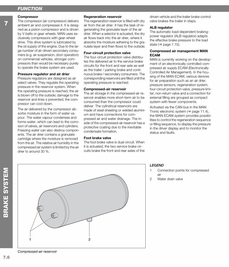
LEGEND1 Connection points for compressed
air2 Water drain valve
FUNCTION
CompressorThe compressor (air compressor) delivers ambient air and compresses it. It is desig-ned as a piston compressor and is driven by V-belts or gear wheels. MAN uses ex-clusively compressors with gear-wheel drive. This drive system is lubricated by the oil supply of the engine. Due to the lar-ge number of air-driven secondary consu-mers (e.g. air suspension, door operation) on commercial vehicles, stronger com-pressors than would be necessary purely to operate the brake system are used.
Pressure regulator and air drierPressure regulators are designed as air select valves. They regulate the operating pressure in the reservoir system. When the operating pressure is reached, the air is blown off to the outside; damage to the reservoir and lines s prevented; the com-pressor can cool down.
The air delivered by the compressor ab-sorbs moisture in the form of water va-pour. The water vapour condenses and forms water, which can lead to the corro-sion of valves, air reservoirs and cylinders. Freezing water can also destroy compon-ents. The air drier contains a granulate cartridge where the moisture is removed from the air. The relative air humidity in the compressed air system is limited by the air drier to around 30 %.
Regeneration reservoirThe regeneration reservoir is filled with dry air from the air drier. It has the task of re-generating the granulate layer of the air drier. When a selector is actuated, the dry air flows back into the air drier, where it absorbs the moisture adhering to the gra-nulate layer and then flows to the outside.
Four-circuit protection valveThe four-circuit protection valve distribu-tes the delivered air to the service brake circuits for the front and rear axle as well as the trailer / parking brake and conti-nuous brake / secondary consumers. The corresponding reservoirs are filled until the operating pressure is reached.
Compressed-air reservoirThe air storage in the compressed-air re-servoir enables more short-term air to be consumed than the compressor could deliver. The cylindrical reservoirs are made of steel sheeting or welded alumini-um and have connections for com-pressed air and water drainage. The in-side of the compressed-air reservoir has a protective coating due to the inevitable condensate formation.
Foot brake valveThe foot brake valve is dual-circuit. When it is actuated, the two service brake cir-cuits brake the front and rear axles of the
driven vehicle and the trailer brake control valve brakes the trailer in steps.
ALB regulatorThe automatic load-dependent braking-power regulator (ALB regulator) adapts the effective brake pressure to the load state (➜ page 7.15).
Compressed air management MAN ECAMMAN is currently working on the develop-ment of an electronically controlled com-pressed air supply ECAM (Electronically Controlled Air Management). In the hou-sing of the MAN ECAM, various devices for air preparation such as an air drier, pressure sensors, regeneration system, four-circuit protection valve, pressure limi-ter, non-return valve and a connection for external filling are grouped as compact system with fewer components.
Activated via the CAN bus in the MAN Tronic electronic system (➜ page 11.4), the MAN ECAM system provides possibi-lities to control the regeneration sequence or filling sequence, to display the pressure in the driver display and to monitor the status and faults.

7.7
7
BR
AK
E S
YS
TE
M
Com
pone
nts
x
FUNCTION
1 Cylinder head2 Intermediate plate with intake and exhaust valve3 Cylinder4 Piston5 Conrod6 Crankcase7 Crankshaft
a Outside air with ambient pressure (no pressure, i.e. no excess pressure)
b Compressed air with brake-air pressure (maxi-mum operating pressure created by the com-pressor)
Compressor
567
1 2
a b
3 4
7.8
7
BR
AK
E S
YS
TE
M
Com
pone
nts
x
Diaphragm brake cylinder
a b
1 2 43
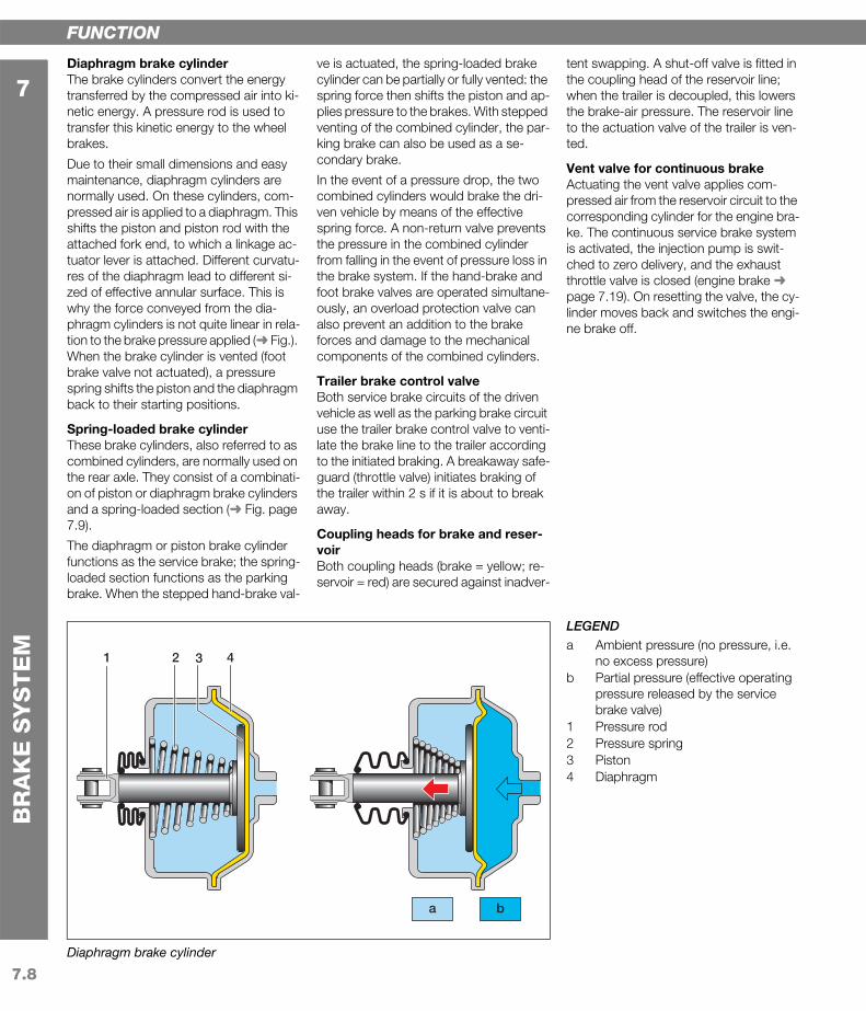
LEGENDa Ambient pressure (no pressure, i.e.
no excess pressure)b Partial pressure (effective operating
pressure released by the service brake valve)
1 Pressure rod2 Pressure spring3 Piston4 Diaphragm
FUNCTION
Diaphragm brake cylinderThe brake cylinders convert the energy transferred by the compressed air into ki-netic energy. A pressure rod is used to transfer this kinetic energy to the wheel brakes.
Due to their small dimensions and easy maintenance, diaphragm cylinders are normally used. On these cylinders, com-pressed air is applied to a diaphragm. This shifts the piston and piston rod with the attached fork end, to which a linkage ac-tuator lever is attached. Different curvatu-res of the diaphragm lead to different si-zed of effective annular surface. This is why the force conveyed from the dia-phragm cylinders is not quite linear in rela-tion to the brake pressure applied (➜ Fig.). When the brake cylinder is vented (foot brake valve not actuated), a pressure spring shifts the piston and the diaphragm back to their starting positions.
Spring-loaded brake cylinderThese brake cylinders, also referred to as combined cylinders, are normally used on the rear axle. They consist of a combinati-on of piston or diaphragm brake cylinders and a spring-loaded section (➜ Fig. page 7.9).
The diaphragm or piston brake cylinder functions as the service brake; the spring-loaded section functions as the parking brake. When the stepped hand-brake val-
ve is actuated, the spring-loaded brake cylinder can be partially or fully vented: the spring force then shifts the piston and ap-plies pressure to the brakes. With stepped venting of the combined cylinder, the par-king brake can also be used as a se-condary brake.
In the event of a pressure drop, the two combined cylinders would brake the dri-ven vehicle by means of the effective spring force. A non-return valve prevents the pressure in the combined cylinder from falling in the event of pressure loss in the brake system. If the hand-brake and foot brake valves are operated simultane-ously, an overload protection valve can also prevent an addition to the brake forces and damage to the mechanical components of the combined cylinders.
Trailer brake control valveBoth service brake circuits of the driven vehicle as well as the parking brake circuit use the trailer brake control valve to venti-late the brake line to the trailer according to the initiated braking. A breakaway safe-guard (throttle valve) initiates braking of the trailer within 2 s if it is about to break away.
Coupling heads for brake and reser-voirBoth coupling heads (brake = yellow; re-servoir = red) are secured against inadver-
tent swapping. A shut-off valve is fitted in the coupling head of the reservoir line; when the trailer is decoupled, this lowers the brake-air pressure. The reservoir line to the actuation valve of the trailer is ven-ted.
Vent valve for continuous brakeActuating the vent valve applies com-pressed air from the reservoir circuit to the corresponding cylinder for the engine bra-ke. The continuous service brake system is activated, the injection pump is swit-ched to zero delivery, and the exhaust throttle valve is closed (engine brake ➜ page 7.19). On resetting the valve, the cy-linder moves back and switches the engi-ne brake off.

7.9
7
BR
AK
E S
YS
TE
M
Com
pone
nts
x
FUNCTION
Driving position of the brakea Ambient pressure (no pres-
sure, i.e. no excess pressure)b Partial pressure (effective ope-
rating pressure released by the service brake valve)
c Reservoir pressure (maximum operating pressure created by the compressor)
1 Fork end2 Pressure rod3 Bellows4 Pressure spring (diaphragm
brake cylinder)5 Piston6 Diaphragm7 Pressure bolt8 Pressure spring (spring-loa-
ded cylinder)9 Piston10 Combined cylinder housing
Service brake position => Area between driving position
and maximum adjustment tra-vel for full braking
Parking brake position => Braking effect only from pres-
sure spring (spring-loaded cylinder)
Spring-loaded brake cylinder (combined cylinder) – function
1 2 3 4 5 6 7 8 9 10
a b c
7.10
7
BR
AK
E S
YS
TE
M
7.4W
heel
bra
kes
7.4.
1Gen
eral
x
Internally ventilated disc brake on the TGA
BASIC PRINCIPLES
Friction brakesFriction brakes are used as wheel brakes in commercial vehicles. They transform the kinetic energy of the parts that rub against one another into thermal energy and a small amount of mechanical materi-al removal.
Two types of friction brake are distingu-ished:
Drum brakes
Disc brakes
The greater the force required for a certain braking effect, the lower the efficiency of the brake. The braking coefficient C* indi-cates the efficiency of a brake, but says nothing about the quality of a brake. This is defined above all by the braking power, responsiveness and controllability that can be achieved. Despite the lower C* va-lue of the disc brake, it is superior to the drum brake in all three areas. The follo-wing braking distances from 80 km/h confirm this:
60 metres with drum brakes and a brake pressure of 8 bar
45 metres with disc brakes and a brake pressure of 10 bar
42 metres with disc brakes and the electronic brake system (EBS ➜ page 7.18).
FUNCTION
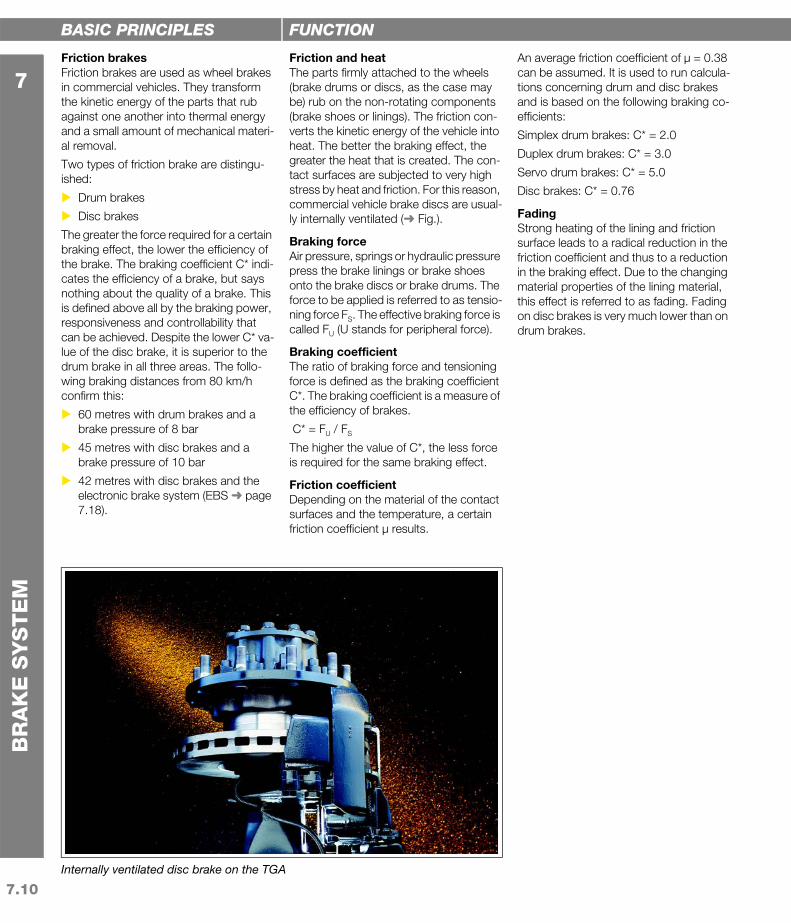
Friction and heatThe parts firmly attached to the wheels (brake drums or discs, as the case may be) rub on the non-rotating components (brake shoes or linings). The friction con-verts the kinetic energy of the vehicle into heat. The better the braking effect, the greater the heat that is created. The con-tact surfaces are subjected to very high stress by heat and friction. For this reason, commercial vehicle brake discs are usual-ly internally ventilated (➜ Fig.).
Braking forceAir pressure, springs or hydraulic pressure press the brake linings or brake shoes onto the brake discs or brake drums. The force to be applied is referred to as tensio-ning force FS. The effective braking force is called FU (U stands for peripheral force).
Braking coefficientThe ratio of braking force and tensioning force is defined as the braking coefficient C*. The braking coefficient is a measure of the efficiency of brakes.
C* = FU / FS
The higher the value of C*, the less force is required for the same braking effect.
Friction coefficientDepending on the material of the contact surfaces and the temperature, a certain friction coefficient µ results.
An average friction coefficient of µ = 0.38 can be assumed. It is used to run calcula-tions concerning drum and disc brakes and is based on the following braking co-efficients:
Simplex drum brakes: C* = 2.0
Duplex drum brakes: C* = 3.0
Servo drum brakes: C* = 5.0
Disc brakes: C* = 0.76
FadingStrong heating of the lining and friction surface leads to a radical reduction in the friction coefficient and thus to a reduction in the braking effect. Due to the changing material properties of the lining material, this effect is referred to as fading. Fading on disc brakes is very much lower than on drum brakes.

7.11
7
BR
AK
E S
YS
TE
M
7.4.
2Dru
m b
rake
s7.
4.2.
1Sim
ple
x an
d d
uple
x dr
um b
rake
sx
S-cam simplex drum brake and duplex drum brake
791 2 43 82 75 6
A B
LEGENDA Simplex drum brakeB Duplex drum brake1 Leading shoe2 Brake lining3 Sliding roller4 S-cam5 Brake camshaft6 Brake drum7 Return spring8 Trailing shoe9 Simplex brake cylinder
BASIC PRINCIPLES
Drum brakesDrum brakes consist of rotating drums firmly attached to the wheels. The brake shoes are firmly fixed to the axles. The brake cylinder presses indirectly on the brake shoes (via mechanical elements) onto the inside of the brake drum and thus brakes the wheels.
As a general principle, distinctions are made according to the arrangement of the brake shoes, the force application and the adjustment simplex and duo drum brakes.
For a long time, drum brakes were regar-ded as the optimised wheel brakes for commercial vehicles. Their closed designs means that drum brakes are protected against exterior influences such as mois-ture and dirt. They also have good braking coefficients (➜ page 7.10).
However, the poor heat dissipation and above all the coefficient fluctuations (fa-ding) that occur due to thermal loads are the main reasons for the fact that drum brakes are being replaced to an increa-sing extent by disc brakes.
FUNCTION
Simplex drum brakesIn the case of the simplex brake, the two brake shoes on one side are pressed apart (➜ Fig.). The lower fastening/pivot points of the shoes are firmly mounted. The direction of rotation of the brake drum means that the tensioning force on one brake shoe is supported by the frictional force (leading brake shoe); on the other shoe, the frictional force counteracts the tensioning force (trailing brake shoe). A disadvantage is the radically different bra-king effect of the two brake shoes. This also applies to the wedge drum brake. For the same reason, the leading shoe is sub-jected to higher wear than the trailing shoe.
Depending on the application of the bra-king force, simplex drum brakes are bro-ken down into cylinder, wedge and S-cam drum brakes.
Cylinder simplex brakeOn the cylinder brake, tension is applied by a floating pressure piston which is acti-vated hydraulically and generates forces of equal dimension in both directions. It is not used in commercial vehicles.
Wedge simplex brakeThe wedge brake is activated by an exte-rior pneumatic or hydraulic cylinder (➜ page 7.14). The wedge moved by the cy-linder spreads the two brake shoes apart.
The wedge brake is used above all in air-braked, light and medium-weight com-mercial vehicles.
S-cam simplex brakeThe drum brake used most frequently in heavy commercial vehicles is the S-cam brake. The S-cam is seated on the brake camshaft, which is turned by a linkage ac-tuator (➜ Fig. page 7.14). The S-cam is activated from the outside by means of a pneumatic brake cylinder. This, together with the fixed tension application, leads to virtually identical lining wear on the leading and trailing shoes. The S-cam brake re-quires a great deal of tension application work at a relatively low braking coefficient (➜ page 7.10).
Duplex drum brakeThis design has two leading brake shoes with a fixed centre of motion, actuated by simplex brake cylinders. The self-energi-sing effect in the main direction of rotation is particularly large.

7.12
7
BR
AK
E S
YS
TE
M
7.4.
2.2D
uo d
rum
bra
kes
x
Duo drum brakes
1 312 2 64
A B
5
LEGENDA Duo-duplex brakeB Duo power brake1 Brake linings2 Dual-action brake cylinder3 Brake drum4 Primary shoe5 Floating support bearing6 Secondary shoe
BASIC PRINCIPLES
Duo drum brakesCompared to simplex brakes, duo drum brakes achieve better measurements. Ho-wever, on account of the high sensitivity to fading (strong fluctuations in the braking coefficient, ➜ page 7.10) they are used less and less frequently.
FUNCTION
Duo brake principleIn the case of duo drum brakes, symmet-rical forces are applied on both sides of the brake shoes. The brake shoes are this pressed onto the drums at the top and bottom (➜ Fig.). This is why the same bra-king force characteristics and self-energi-sation result for both directions of rotation.
Due to the design, duo drum brakes are activated hydraulically without com-pressed-air support.
Duo-duplex drum brakeOn the duo-duplex drum brake, two dual-action cylinders or also single-action hy-draulic cylinders are used. The double force application means that this brake has two leading shoes and thus virtually the same brake lining wear on both brake shoes.
Duo power drum brakeThe power drum brake is normally activa-ted hydraulically by a dual-action cylinder. The supporting force of the primary shoe on the floating support bearing creates additional tensioning force for the se-condary shoe. This principle – due to the self-energising braking effect – means that very high braking coefficients can be achieved.
Power drum brakes are used in light com-mercial vehicles up to 7.5 t without com-pressed-air support.

7.13
7
BR
AK
E S
YS
TE
M
7.4.
3Dis
c br
akes
x
Floating calliper disc brake made by Knorr
a b
3
F
1 4 52
LEGENDa Ambient pressure (no pressure, i.e.
no excess pressure)b Partial pressure (effective operating
pressure released by the service brake valve)
1 Brake disc (internally ventilated)2 Brake calliper3 Brake linings4 Piston (pressure piston)5 Diaphragm brake cylinder
BASIC PRINCIPLES
Disc brakesOn account of the rising requirements with regard to driving performance, disc brakes are being used to an increasing degree in commercial vehicles.
Compared to drum brakes, disc brakes have a number of decisive advantages:
Better controllability of the braking effect
The same wear of the brake linings on the inside and outside of the discs if the thermal load is correctly dimensio-ned
Relatively constant coefficient charac-teristics with low fading tendency
Good cooling (possibly internally venti-lated)
MAN equips most 4x2 commercial vehic-les of the Evolution model series LE as well as the Trucknology Generation with disc brakes on both axles.
FUNCTION
Principle of the disc brakeThe internally ventilated brake disc (➜ Fig.) used mostly in the field of commercial vehicles is firmly attached to the corres-ponding wheel. When the wheel turns, the disc also turns and runs through the brake calliper. The brake linings are located on the left and right of the brake disc in the brake calliper. When the brake is opera-ted, they are pressed together, and press from both sides onto the brake disc and with braking effect. A general distinction is made in the case of brake callipers bet-ween fixed callipers and floating callipers.
Fixed calliper disc brakeWith this design, one or more brake pis-tons are used on each side. The fixed cal-liper surrounds the brake disc and is firmly connected to the axle. The brake pistons located to the right and left of the disc press the brake linings with very even pressure against the disc. Due to the high space requirement and more complex manufacturing (compared to that for the floating calliper brake), the use of fixed cal-liper disc brakes is on the decline.
Floating calliper disc brakeThe brake pistons on these brake calli-pers, which are also referred to as sliding callipers, are only seated on one side. On commercial vehicles, two pistons (pressu-re pistons) are normally used.
The force F applied by the diaphragm bra-ke cylinder is transferred onto the pistons (➜ Fig.). These exert the force F' on the brake lining mounted on inside of the ve-hicle. The reactive force that arises shifts the floating calliper and also presses the second brake lining with force F" onto the brake disc. The two forces are of equal si-ze: F' = F" (➜ Fig.).
On account of its numerous advantages, the floating calliper disc brake has be-come the predominant brake disc above all in the field of commercial vehicles:
Low space requirement between brake disc and wheel nave
Low weight
Favourable thermal conditions (no hydraulic line in the zone above the brake disc which is exposed to high thermal stress)
A disadvantage can be the uneven pres-sing force of the brake linings with increa-sed friction in the movement of the floating calliper.

7.14
7
BR
AK
E S
YS
TE
M
7.4.
4Set
tings
of t
he li
nkag
e ac
tuat
or
x
Air gaps on the S-cam brake
1 2 3 4a cb
Wedge drum brake
7
3
4
56
1
LEGENDa Air gap due to elasticityb Air gap due to wearc Constructive air gap1 Brake shoe2 Linkage actuator3 Piston rod4 Diaphragm brake cylinder5 Return spring6 Wedge7 Sliding roller
BASIC PRINCIPLES
Air gapThe brake linings on disc and drum brakes are subject to a high level of wear. Abrasi-on of the linings leads to greater gaps over time. Especially in the case of the pneu-matic brake systems used in commercial vehicles, this so-called air gap has to be checked and adjusted in good time. If this is neglected, the piston stroke becomes larger and the brake response time lon-ger. In extreme cases, the air gap can be-come so large that the diaphragm cylin-ders are no longer able to build up a bra-king effect.
The air gap can be divided into three areas:
Constructive air gap (given) between lining and brake drum / disc
Air gap due to wear of the lining
Air gap due to elasticity in the force transmission between brake cylinder and wheel brake
FUNCTION
Drum brakesIn the case of drum brakes with S-cams, the air gap is adjusted with the help of an automatic linkage actuator.
On braking, an adjuster unit ensures that the linkage actuator "moves on" if the ad-justment travel exceeds a certain value. In this way, the air gap can never exceed the prescribed maximum value.
Manually adjustable linkage actuators are no longer used nowadays. The adjust-ment is made here by manually turning a setting spindle on the push rod.
Wedge drum brakesIn the case of wedge drum brakes (➜ Fig.), the air gap is also divided into three areas construction, wear and elasticity.
Disc brakesDisc brakes have an internal adjustment mechanism. Here, the rotational move-ment of a threaded spindle ensures even shifting of the brake linings and this a con-stant air gap.
The disc brakes on commercial vehicles are normally equipped with sensors that indicate the maximum permitted wear to the driver by means of a warning lamp. There are also systems that provide exact information on the current state of the bra-ke wear at any time.

7.15
7
BR
AK
E S
YS
TE
M
7.5B
raki
ng-p
ower
con
trol s
yste
ms
7.5.
1Aut
omat
ic, l
oad-
dep
ende
nt b
raki
ng-p
ower
con
trol
x
Brake pressure with automatic, load-dependent braking-power control
a
pE
pA
b
c
d
LEGENDa Vehicle emptyb Vehicle half loadedc Vehicle fully loadedd Start of controlpA Output pressure (effective brake
pressure)pE Input pressure (created operating
pressure)
BASIC PRINCIPLES
ALB regulatorNowadays, automatic load-dependent braking-power control (ALB) is regarded as an indispensable facility for commercial vehicles.
Depending on the load state, there are dif-ferent pressure forces between the road surface and wheels. The brake system must be configured for the maximum load. With a partial load, excessively high brake forces can block the wheels.
Fitting an ALB regulator enables adaptati-on of the brake forces to the lower axle loads when the vehicle is empty or only partially loaded. Depending on the load state, the effective braking force is redu-ced or maximised. The vehicle then achie-ves its optimised braking power in every load state without the wheels blocking.
A distinction is made between manually adjustable and automatic braking-power regulators. Manually adjustable ALB val-ves are no longer permitted under EU re-gulations.
FUNCTION
Braking power regulatorThe braking power regulators (also refer-red to as ALB valves) are placed in the compressed-air line between the service brake valve and the brake cylinder. The set value for commercial vehicles with me-chanical suspension is the compression travel; on vehicles with air suspension, this is the air-spring bellows pressure.
The inlet and outlet of the ALB valve are changed by the set value in such a way that the brake cylinders are either applied full pressure or only partial pressure. In most cases, a control valve with variable reaction surface is used for this; it reduces the input pressure in relation to the output pressure depending on the set value. Me-chanically activated braking power regula-tors are attached to the vehicle frame. They take up the spring compression from each axle by means of a lever via linkage.
ALB regulators are fitted in the rear-axle brake circuit (➜ page 7.5).
Braking power limiterWith a braking power limiter, another in-crease in the braking force from a certain point (switchover point) onwards is pre-vented, depending on spring compressi-on.
Braking power reducerLoad-dependent braking power reducers ensure that the brake forces are reduced
after the switchover point has been rea-ched when subjected to a load.
Braking power controllerEven with unfavourable loading situations, these units ensure optimised braking po-wer distribution. The effective brake pres-sure is continuously balanced out across the entire range of all load states. Braking power controllers are very complex and expensive.

7.16
7
BR
AK
E S
YS
TE
M
7.5.
2Ant
iblo
ck sy
stem
AB
S
x
Power transmission and slip
80
c
100604020
1,0
0,8
0,6
0,4
0,2
[%]
d
a bµ HF
µ HF
λ
Antiblock system ABS (function)
4 5
1
2 3
LEGENDa Stable rangeb Unstable rangec Free rolling wheeld Blocked wheel1 Service brake valve2 Pressure control valve3 Control unit4 Brake cylinder5 Speed sensorµHF Power transmission (coefficient of
static friction)λ Brake slip
BASIC PRINCIPLES
Antiblock system ABSHow well the forces that take effect on braking are transferred depends on the power transmission and this in turn on the brake slip (sliding movement) between the tyres and road surface (➜ Fig.). With in-creasing slip, the usable power transmis-sion also increases (stable range). As the braking force becomes greater, the slip continues to rise: the power transmission becomes smaller. In the end, the wheels block (unstable range).
The antiblock system ABS prevents the wheels from blocking by reducing the bra-king force. A vehicle equipped with ABS remains stable and steerable and maintains its direction even with full bra-king on a slippery road surface, as the wheels do not block. On truck-trailer units and semitrailer trucks, the ABS system also prevents the trailer or semitrailer from jack-knifing on full braking.
Since 1991, ABS has been legal prescri-bed on commercial vehicles. Trucks for trailer operation and semitrailer tractors > 16 t, buses as of 12 t and trailers with more than 10 t permitted total weight must be equipped with ABS. MAN also of-fers ABS within the framework of the opti-mised electronic brake system EBS (➜ page 7.18).
FUNCTION
Components of the ABS systemAntiblock systems consist of speed sen-sors, an electronic control unit and pres-sure control valves. In each individual bra-ke cylinder, the brake pressure is reduced or kept constant depending on require-ments.
The speed sensor determines the rotatio-nal speed of the wheel; in the electronic control unit, this is converted into the ve-hicle speed (reference speed). The micro-processors in the control unit use the ro-tational speed and reference speed to cal-culate the slip of each individual wheel. The signals "wheel deceleration" and "wheel slip" are then used to determine the blocking tendency of the individual wheels; The pressure control valves are activated and regulate the brake pressure in the individual brake cylinders.
Depending on the commercial vehicle and number of controlled axles, 1-axle, 2-axle and 3-axle ABS systems are available. The best braking characteristics are achieved when the towing vehicle and trailer/semitrailer have separate ABS sys-tems.
Individual regulation of the front axleHere, the optimised brake pressure is set individually for each wheel of the front ax-le. This system achieves the shortest bra-king distances. In the case of µ-split con-ditions (different surface for right-hand
and left-hand wheel, e.g. snow and as-phalt), however, a greater yawing moment arises (➜ page 18.10). The vehicle is then more difficult to keep under control. This form of regulation is not used at MAN.
Select-Low regulation of the front axleOnly one pressure control valve is used per axle. Most important for activation in the event of µ-split conditions is always the wheel with the lower friction value (se-lect low). As in this case the wheel with the higher frictional value is underbraked, lon-ger braking distances than with individual regulation are the result.
Individual regulation of the front axle, modifiedA pressure control valve is used for each wheel. The braking pressure difference between the right-hand and left-hand front wheels is limited to a permitted level. This results in a slightly longer braking dis-tance than with individual regulation, but the yawing moment is reduced and the vehicle remains under control even in the event of critical braking manoeuvres.
7.17
7
BR
AK
E S
YS
TE
M
7.5.
3Tra
ctio
n co
ntro
l sys
tem
ASR
x
ASR engine control circuit (operating principle)
1
2
b a
43
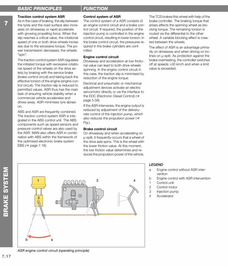
LEGENDa Engine control without ASR inter-
ventionb Engine control with ASR intervention1 Control unit2 Control motor3 Injection pump4 Accelerator
BASIC PRINCIPLES
Traction control system ASRAs in the case of braking, the slip between the tyres and the road surface also incre-ases on driveaway or rapid accelerate with growing propelling force. When the slip reaches a critical value, the rotational speed of one or both drive wheels increa-ses due to the excessive torque. The po-wer transmission decreases; the wheels "spin".
The traction control system ASR regulates the initiated torque with excessive rotatio-nal speed of the wheels on the drive ax-le(s) by braking with the service brake (brake control circuit) and taking back the effective torsion of the engine (engine con-trol circuit). The traction slip is reduced to permitted values. ASR thus has the main task of ensuring vehicle stability when a commercial vehicle accelerates and drives away. ASR minimises tyre abrasi-on.
ABS and ASR are frequently combined. The traction control system ASR is inte-grated in the ABS control unit. The ABS components such as speed sensors and pressure control valves are also used by the ASR. MAN also offers ASR in combi-nation with ABS within the framework of the optimised electronic brake system EBS (➜ page 7.18).
FUNCTION
Control system of ASRThe control system of a ASR consists of an engine control circuit and a brake con-trol circuit. If required, the position of the injection pump is controlled in the engine control circuit, resulting in lower torsion. In the brake control circuit, the pressures re-quired in the brake cylinders are cont-rolled.
Engine control circuitDriveaway and acceleration at low frictio-nal value can lead to both drive wheels spinning. In the engine control circuit in this case, the traction slip is minimised by reduction of the engine torque.
Electrical and pneumatic or mechanical adjustment devices activate an electric servomotor directly or via the interface to the EDC (Electronic Diesel Control) (➜ page 5.58).
If the ASR intervenes, the engine output is reduced by adjustment of the delivery-rate control of the injection pump, which also reduces the propulsion power (➜ Fig.).
Brake control circuitOn driveaway and when accelerating on µ-split, it frequently occurs that a wheel of the drive axle spins. This is the wheel with the lower friction value. At this moment, the low friction value determines and re-duces the propulsion power of the vehicle.
The TCS brakes this wheel with help of the brake controller. The braking torque that arises affects the spinning wheel as blo-cking torque. The remaining torsion is routed via the differential to the other wheel. A variable blocking effect is crea-ted between the wheels.
The effect of ASR is an advantage prima-rily on driveaway and when driving on inc-lines on µ-split. As protection against the brake overheating, the controller switches off at speeds >30 km/h and when a limit value is exceeded.

7.18
7
BR
AK
E S
YS
TE
M
7.5.
4Ele
ctro
nic
brak
e co
ntro
l
x
Electronically controlled brake system EBS
BA
C
A
B
1 2 3 4 5
67891011
LEGENDA Compressed air reservoir, front axle
(FA)B Compressed air reservoir, rear axle
(RA)C Compressed air reservoir, trailer1 Control unit EBS2 Pressure control module FA3 Load sensor RA4 Pressure control module RA5 CAN bus to trailer6 Control pressure, trailer7 Wheel brake cylinder RA8 Trailer control module9 Wheel brake cylinder FA10 Speed sensor with impulse ring11 Service brake valve
BASIC PRINCIPLES
Electronic brake system EBSThe drive and braking operation of com-mercial vehicles can be optimised with the help of an electronic brake system, EBS. The basic function of the electropneu-matic brake EPB as well as the functions antiblock system (ABS ➜ page 7.16) and traction control system (ASR ➜ page 7.17) are integrated in the electronic brake system.
The electronic adaptation of the braking force to each braking situation can also help to reduce wear on the corresponding components, thus improving the econo-my of the entire brake system. It also makes monitoring and maintenance of the brake system easier.
The entire vehicle electronics are networ-ked (CAN = Controller Area Network), which means that data can be interchan-ged between EBS and other systems (e.g. EDC ➜ page 5.58). The harmonisation of the individual systems to one another that this enables leads to further improve-ments in the operation. Within the MAN BrakeMatic, the function of the EBS is harmonised with the use of a retarder and engine brake.
FUNCTION
Operating principle of the EBSThe electronic brake system EBS works with an electronic control signal of the bra-ke pedal sensors; this is processed elec-tronically in the EBS control unit and transferred from there to the pressure control modules practically without delay (➜ Fig.).
The pressure control modules set the re-quired brake pressure in the wheel brake cylinders pneumatically and simultane-ously pass on the sensor signals from the wheel area to the EBS control unit. The power transmission between the tyres and road surface can be exploited up to the maximum limit value.
The pneumatic working circuits to operate the brake cylinder in the towing vehicle and trailer are set up in the same way as the dual-circuit dual-line brake system (➜ page7.4). In the event of malfunctions, the EBS becomes a purely pneumatic brake system with two pneumatic circuits. On braking, pressure is built up in the brake cylinders without control, depending on the position of the brake pedal.
The electronic - and thus immediate - ac-tivation of the wheel brakes by the pressu-re control modules creates a direct bra-king feel for the driver similar to that on a passenger car.
Expansion possibilities for EBSThe drive and braking operation can be optimised by means of the EBS for diffe-rent equipment variants with the same basic concept of the brake system. Sys-tems such as trailer control and brake li-ning wear control for even lining abrasion on all wheels are integrated in the EBS. An off-road ASR adapts the slip as required to special driving conditions. Wear fore-casts and final wear of the brake linings are shown in the driver display.
The EBS can be supplemented with dri-ving dynamics control of the electronic stability program (ESP ➜ page 11.12). In conjunction with the series-standard elec-tronic coupling force control, even chan-ging truck-trailer combinations can be harmonised and optimised. All the wheels of a vehicle combination that are equip-ped with this electronic brake control bra-ke synchronously and depending on the percentages by mass that take effect. This can significantly reduce the impact and coupling forces that occur within the combination.
MAN can also provide an optional dis-tance-controlled cruise control system ACC (Adaptive Cruise Control ➜ page 11.18).

7.19
7
BR
AK
E S
YS
TE
M
7.6C
ontin
uous
bra
kes
7.6.
1Eng
ine
brak
es
7.6.
1.1O
verv
iew
x
Braking power chart, D2876LF engine
1400 1600 1800 2000 2200 n
PB
140
120
100
80
60
40
20
0
a
b
[%]
[min–1]
LEGENDCurves:a Engine braking power with MAN
EVBb Braking power only with one
exhaust flap engine brakeFormula symbols:n Engine speedPB Engine braking power
BASIC PRINCIPLES
Continuous brakesThe pneumatic wheel brakes are not desi-gned for continuous operation. When operated for longer periods (driving down-hill), thermal overload occurs if no more additional braking power is available. Thermal overload leads to fading (➜ page 7.10) and in extreme cases to brake failu-re. On commercial vehicles with high total weights, an additional continuous brake that is independent of the power supply of the service brake makes sense.
In commercial vehicles, two types of con-tinuous brake are used primarily:
Engine brakes (primary brake system)
Retarders (secondary brake system)
Engine brakesAn engine operated with a reversed po-wer flow, i.e. drive axle – gearbox – engi-ne, uses its drag torque as a brake. To im-prove braking power, the exhaust gas flow is throttled during the exhaust cycle or the expansion work is limited by means of specific decompression.
All engine brake systems are primary bra-ke systems, i.e. they work depending on the engine speed (higher engine speed => higher braking power).
FUNCTION
Exhaust valve brakeThe exhaust gases are accumulated by a throttle valve built into the exhaust line. On exhausting the cylinder charge, the engine performs additional work (against the back pressure in the exhaust line). The back pressure is built up by a throttle valve in the exhaust tract. The throttle valve is switched on when required by the driver per compressed air (circuit 4 of the EU brake system ➜ page 7.4). Against the counterpressure created by the flap, each individual cylinder of a four-stroke engine must exhaust in the fourth combustion cy-cle (➜ page 5.7). So as not to damage the components of the valve gear, the maxi-mum back pressure that arises is regula-ted by a pressure limitation device.
Engine braking powerThe engine braking power in a commer-cial vehicle with exhaust valve brake is composed of drag torque and braking po-wer.
The drag power is the power output ne-cessary to "drive" the engine. The braking power is defined as the power output achieved by throttling the exhaust gas flow during the exhaust cycle. The total engine braking power available for the de-celeration of the vehicle is the sum of the drag power and braking power.
Reinforced engine brake systems such as the EVB or the constant throttle engine
brake (➜ page 7.20) use specific decom-pression during the compression cycle to reduce the compression work and thus reduce the expansion energy (driving po-wer). Systems of this nature achieve noticeably better braking power than pure exhaust flap engine brakes, but are more complex and expensive.
The EVB improves the braking power by up to 65 % in relation to the braking effect of a conventional exhaust flap engine bra-ke (throttle-valve brake).
The braking power chart of the D2876LF engine (➜ Fig.) shows the increase of 65 % in engine speed of 2000 rpm (rated speed).

7.20
7
BR
AK
E S
YS
TE
M
7.6.
1.2R
einf
orce
d en
gine
bra
ke s
yste
ms
x
Constant throttle
3
6
4
5
2
1
LEGEND1 Compressed air2 Exhaust flap3 Exhaust4 Constant throttle5 Intake6 Piston
BASIC PRINCIPLES
Reinforced engine brake systemsConventional exhaust flap engine brakes do not inadequately meet the high re-quirements of increasingly more powerful diesel engines.
The standard engine brake with exhaust flap exploits the braking energy of the en-gine exclusively in the gas exchange cyc-le. The actual compression takes place without loss, i.e. during the compression and expansion cycle no braking energy of the engine can be used despite operation of the engine brake (compression and ex-pansion are not hindered).
The various commercial vehicle manufac-turers have developed different methods of releasing braking energy of the engine even during the compression and expan-sion cycle.
Typical methods of enhancing the braking power in combination with an exhaust val-ve brake are:
Constant throttle from Mercedes-Benz
Exhaust valve brake EVB from MAN
Jake Brake from Renault
Volvo Engine Brake VEB
FUNCTION
Constant throttleThis method developed by Mercedes-Benz enables specific decompression du-ring of the combustion cycle with the in-stallation of an additional valve (➜ Fig.).
When the engine brake is operated, the valve referred to as a constant throttle is opened: the compression of the air in the cylinder is inadequate; less work is avai-lable for the subsequent expansion. The loss of expansion work is thus used as braking energy. The constant throttle can also be used without an exhaust valve brake. However, an improvement compa-red to the engine braking power that can be achieved by conventional means only results if both methods are used.
Exhaust Valve Brake MAN EVBThe Exhaust Valve Brake MAN EVB achie-ves a similar effect by means of an intelli-gent innovation with minimum overhead. Due to its operating principle, it is also re-ferred to as a rocker arm brake.
Presented at the IAA in 1996, the MAN EVB engine brake provides more efficien-cy with lower construction overhead com-pared to the other methods.
In the following sections, the components of the MAN EVB (➜ Fig. page 7.21) and their function (➜ page 7.22 f.) are shown separately.

7.21
7
BR
AK
E S
YS
TE
M
7.6.
1.3M
AN
eng
ine
brak
e, E
xhau
st V
alve
Bra
ke (E
VB
)
x
FUNCTION
1 Valve cover2 Push rod3 Rocker arm4 Oil supply in rocker arm shaft5 Oil supply in the rocker arm
6 Non-return valve7 Setting screw8 Brace 9 Relief hole10 High-pressure area
11 Piston stroke limitation12 Rocker arm piston13 Exhaust valve bridge14 Valve spring15 Exhaust valve
MAN EVB – components
1 2 3 4 5 6 7 8 9 10 11 12 13

7.22
7
BR
AK
E S
YS
TE
M
MA
N e
ngin
e br
ake,
Exh
aust
Val
ve B
rake
(EV
B)
x
FUNCTION
Jumping of the valveIn the case of the EVB, MAN engineers ex-ploit an effect that ensures brief opening of the exhaust valve ("jumping"). This ef-fect occurs on all throttle-valve brakes normally used nowadays and is exploited in the EVB to enhance braking power.
If the exhaust throttle valve is closed, the exhaust pressure rises in the exhaust duct prior to compression (bottom dead cen-tre) to such a strong degree that the ex-haust valve is briefly pressed upwards by the pressure wave of a neighbouring cylin-der. A piston in the rocker arm to which engine oil pressure is continuously applied prevents the valve from closing again. A stroke of 1 to 2 mm remains, which means that in the compression stroke in the engine a part of the compressed air can low out of the cylinder. When the top dead centre is reached, this opening is re-tained. The pressure on the piston, which is then moving downwards, is conside-rably reduced; the braking power is im-proved.
Throttling the exhaust gases means that both the upward and downward move-ment of the engine piston can be used for braking.
At the start of the exhaust cycle, the ro-cker arm movement opens the relief hole; the oil escapes and relieves the load on the piston. In the subsequent induction stroke, the exhaust valve can close again.
Induction stroke (➜ detail A):both exhaust valves are closed, the rocker arm piston makes contact with the valve due to engine oil pressure. The brace forms the seal.
Legend (excerpt ➜ page 7.21)8 Brace12 Rocker arm piston13 Exhaust valve bridge14 Valve spring15 Exhaust valve
MAN exhaust valve brake – position in induction stroke
A
8
12
1315
14
A
15

7.23
7
BR
AK
E S
YS
TE
M
MA
N e
ngin
e br
ake,
Exh
aust
Val
ve B
rake
(EV
B)
x
FUNCTION
Compression and combustion stroke(➜ detail B): with the exhaust throttle valve closed, pressure waves build up in the exhaust duct, leading to brief re-opening of the exhaust valves. The rocker arm piston in the exhaust valve bridge, to which engine oil pressure is applied, prevents a valve from closing again and keeps it open slightly during compression and the subsequent combustion stroke by closing the relief hole.
Legend (excerpt ➜ page 7.21)3 Rocker arm5 Oil supply in the rocker arm6 Non-return valve8 Brace9 Relief hole11 Piston stroke limitation12 Rocker arm piston13 Exhaust valve bridge14 Valve spring15 Exhaust valve16 Exhaust cam
Exhaust cycle (➜ detail C):Both exhaust valves are opened via the rocker arm mechanism and the exhaust valve bridge by the exhaust cam. The exhaust valve bridge swings away from the brace. The relief hole is released; the rocker arm piston returns to its original position and makes con-tact with the piston stroke limitation in the exhaust valve bridge.
MAN exhaust valve brake – position in compression and combustion stroke as well as exhaust stroke
ca. 2 mm
B
B
8
12
13
5 6
13
14
C
C
3
13
983
116

7.24
7
BR
AK
E S
YS
TE
M
7.6.
1.4M
AN
eng
ine
brak
e sy
stem
EV
Bec
x
Electronically controlled exhaust throttle of the EVBec
2
4
3
1
Integration of the MAN EVBec in the brake management system BrakeMatic
6
5
LEGEND1 Exhaust throttle valve2 Control unit3 Pressure sensor (exhaust counter-
pressure)4 Pneumatic adjustment cylinder5 Continuous brake tip switch for
engine brake6 Rocker switch for BrakeMatic
BASIC PRINCIPLES
Engine brake system MAN EVBecAs and enhancement of the proven MAN EVB engine brake (➜ page 7.20), the new engine brake system EVBec (electronical-ly controlled) provides the following ad-vantages:
Braking torque adjustable in three sta-ges
Significantly increased braking power, in particular in the lower engine speed range
Overheating protection for long bra-king operations
Constant braking power no matter whether the engine speed is rising or falling
Simplified function check with diagno-sis possibility
One aim of the EVBec development was to achieve controllability of the engine bra-king power and possible integration of the system in the intelligent brake manage-ment system MAN BrakeMatic. In the MAN BrakeMatic, the EVBec as a conti-nuous brake management system is re-ferred to as a "brakeomat" (➜ page 11.17). It can be used, depending on the vehicle equipment, to activate a pre-acti-vation of the engine brake or of the retar-der in the brake pedal as well as to pre-vent a preset speed from being exceeded.
FUNCTION
Operating principle of the MAN EVBecIn addition to the familiar EVB function principle (➜ page 7.21 ff.), the controlla-bility of the exhaust counterpressure on the EVBec enables a three-stage setting of the braking power. Tolerance-related fluctuations in the braking power can also be balanced out in this way.
The engine braking torque is changed by controlling the exhaust counterpressure for the cylinders. A high exhaust counter-pressure and strong braking effect set in with a large closing angle of the exhaust throttle valve. The closing angle of the ex-haust throttle valve is in turn directly rela-ted to the activation pressure at the pneu-matic adjustment cylinder.
A pressure sensor measures the exhaust counterpressure in the exhaust pipe and passes this information on to the vehicle management computer. The vehicle ma-nagement computer then uses all the available input variables to calculate the required application pressure for the ad-justment cylinder and provides the corre-sponding value by means of the proporti-onal valve.
Overheating protection on the EVBecThe additionally reinforced exhaust valve springs mean that the higher braking po-wer on the EVBec causes no thermal pro-blems for the valve timing.
To protect the engine components against overheating during longer braking operations, the maximum braking torque is reduced depending on the engine speed and time.

7.25
7
BR
AK
E S
YS
TE
M
7.6.
1.5E
ngin
e br
ake
Turb
o br
ake
x
Turbo brake turbine with axial shifting deflector grille
A
B
1
2
Pneumatic adjustment unit for turbine deflector grille
3
4
12
5
LEGENDA Normal drive phase of the engine
with turbochargingB Engine braking phase: Deflector
grille shifted over the turbine1 Turbine housing with turbine2 Turbine deflector grille (axial shifting)3 Axial slider4 Pneumatic adjustment cylinder5 Overrun control device
BASIC PRINCIPLES
Engine brake Turbo brakeAs an enhancement of the naturally aspi-rated engine brake with the usual exhaust gas pressure flap, Mercedes-Benz and Iveco are the first commercial vehicle ma-nufacturers to introduce a supercharged engine brake, the "turbo brake". Activati-on of the exhaust turbocharger in the en-gine braking phase enables an increase in the charge level of the cylinders compared to the normal, reinforced exhaust valve brake (➜ page 7.20), thus achieving further reinforcement of the braking po-wer.
However, compared to the retarder, rela-tively high engine speeds in the engine braking mode are required for effective functioning of the turbo brake. For this re-ason, depending on the driving situation, a downward gearshift can be required.
FUNCTION
Mercedes-Benz turbo brakeThe main component of the supercharged engine brake "turbo brake" is mounted on the exhaust turbocharger. This is a turbine deflector grille, arranged in the nozzle duct of the turbocharger in such a way that it can be shifted axially. In the engine bra-king phase, the deflector grille is shifted over the turbine (➜ Fig.).
The tight turbo brake grille thus leads to increased engine counterpressure and to higher flow speed onto the turbine. This leads to a higher air throughput in the en-gine via the connected turbocharger com-pressor; in conjunction with a constant throttle, this enables a considerable en-hancement in engine braking power. The axial slider for the turbine deflector grille is continuously variable, achieving fine cont-rollability of the turbo brake.
In the normal drive phase, the turbine de-flector grille is pulled out of the nozzle duct again before the turbine, resulting in the familiar operation of an exhaust tur-bocharger (➜ page 5.34).
Overrun control deviceThe overrun control device is intended to exclude excessive stress of the engine both on braking and with drive.
The aim of the overrun control device is to exert a specific influence on the braking power in the same way as an engine bra-
ke cruise control system. In conjunction with the cruise control function, the super-charged engine brake, which initially is only used on heavy commercial vehicles, is also to be used for supercharged pas-senger cars.

7.26
7
BR
AK
E S
YS
TE
M
7.6.
2Ret
arde
rs7.
6.2.
1Hyd
rody
nam
ic r
etar
der
s x
ZF intarder
4
3
5
6
2
1
Braking torque ZF intarder
00
20 40 60 80 100
500
1000
1500
2000
2500
3000
3500
TAb
[Nm]
v [km/h]
1
2
3
4
5TAb,max 500 kW
420 kW
LEGEND1 Connection for power take-off2 Output flange3 Oil reservoir4 Heat exchanger5 Rotor/stator6 Spur gear stageDiagramv Driving speedTAb Braking torque1–5 Braking stagesBasis of calculation for diagram:Rolling radius rdyn = 0.52 mRear axle gear ratio iRA = 3.4Power output limitation 500 kW (420 kW)
BASIC PRINCIPLES
RetardersRetarders are used to further improve the braking power of commercial vehicles. As in the case of engine brakes, they are non-wearing continuous brakes. Retarders re-lieve the load on the service brake and in-crease active safety (➜ page 12.1). They also enhance the economy of commercial vehicles.
Retarders are fitted in the drive train of a commercial vehicle. The transform part of the kinetic energy of the vehicle into heat.
Depending on the installation position, they are categorised as:
Primary retarders (engine-speed-dependent) between the engine and gearbox
Secondary retarder (speed-depen-dent) between the gearbox and drive axle
According to the operating principle and structure, the following are distinguished:
Hydrodynamic retarders (hydraulic retarders)
Electrodynamic retarders
Hydrodynamic secondary retarders are used in most modern COE trucks. Here, the braking effect depends on the driving speed.
FUNCTION
Hydrodynamic retardersHydrodynamic retarders consist of a rotor (rotating) and a stator (stationary) arran-ged in a housing filled with oil. These are also referred to as the brake rotor and brake stator.
The brake rotor is seated on the drive shaft of the retarder; the brake stator is connected to its housing.
The driving movement causes the brake rotor to rotates, setting the oil in the hou-sing in motion. The movement of the oil (and thus the movement of the drive shaft) is braked by the chambers of the brake stator.
The mechanical energy of the drive shaft is converted into kinetic energy of the oil, and this in turn is converted into heat. The braking effect of the retarder rises with the amount and viscosity of the filled oil. The oil conveys the absorbed amount of heat via an oil-water heat exchanger to the coolant of the vehicle engine.
The amount of oil flowing in is controlled by a pneumatic control valve, operated by the driver per hand switch or combined with a foot brake valve.
The drive shaft of the retarder is connec-ted to the output shaft of the engine (pri-mary retarder) or the propshaft (drive shaft) of the vehicle (secondary retarder). In the case of primary retarders in con-
junction with manual gearboxes, their ar-rangement means there is an interruption in the braking effect on changing gear.
IntardersThe intarder is a compact retarder integra-ted in the gearbox housing (➜ Fig.). The braking torque of the ZF intarder has a vir-tually constants course in the lower bra-king stages across a wide speed range (➜ diagram). In the upper stages, the braking power is limited by the cooling capacity of the engine radiator to max. 500 kW.
Integration in the electronics framework provides additional convenience and safe-ty functions during retarder operation (temperature management ➜ page 11.9, "brakeomat" ➜ page 11.17).
The latest systems use a special panel between the rotor and stator. This minimi-ses the air-flow losses when idling without oil and leads to fuel savings.

7.27
7
BR
AK
E S
YS
TE
M
Hyd
rody
nam
ic re
tard
ers
x
FUNCTION
1 Drive shaft2 Rotor3 Stator4 Heat exchanger5 Central oil drainage6 Oil reservoir
Voith retarder, section
1 2 3 4
56
1 2 3

7.28
7
BR
AK
E S
YS
TE
M
7.6.
2.2M
AN
PriT
arde
r
x
Water retarder (blue) on the MAN D2876 CR engine
Structure of the water retarder
78
4 5 61 2 3
LEGEND1 Water retarder fill duct2 Water retarder exhaust duct3 Stator4 Rotor5 Coolant pump6 Coolant ducts (engine cooling cir-
cuit)7 Drive shaft8 Switchover valve water retarder /
coolant pump
BASIC PRINCIPLES
MAN PriTarderMAN PriTarder is an innovative primary brake system. It is a combination of water retarder (WR) and the electronically cont-rolled MAN engine brake system EVBec (➜ page 7.24).
The system intervenes directly in the engi-ne, and is thus referred to as a primary brake system. The direct link to the engine speed provides considerable advantages especially at low and medium speeds compared to the secondary retarders that work at the gearbox output (speed-de-pendent effect). With downward gear-shifts (which take place automatically in combination with the MAN TipMatic gear-shift system), the PriTarder is always pro-vided with the optimised working engine speed.
FUNCTION
Water retarderIn contrast to conventional retarder sys-tems (working medium: oil), the water re-tarder (WR) functions with the water (coolant) of the engine cooling circuit. The kinetic energy of the vehicle that is conver-ted into thermal energy is conveyed by the stator of the water retarder directly to the coolant – no additional oil filling and no oil-water heat exchanger is required.
Coolant pumpThe water retarder is seat on the front of the crankcase. It is driven directly by the crankshaft. The function of a coolant pump is implemented on some versions.
Overheating protection on the PriTar-derThe temperature sensor indicates the coolant temperature to the control unit of the vehicle management computer. If the permitted maximum temperature is ex-ceeded during brake operation, the Pri-Tarder braking power is limited.
EXAMPLE
The primary brake system MAN PriTarder was a worldwide innovation used for the first time on the new D2876 engines.
MAN commercial vehicles of the Truckno-logy Generation TGA achieve a braking power of 600 kW with the MAN PriTarder.
7.29
7
BR
AK
E S
YS
TE
M
7.6.
2.3E
lect
rody
nam
ic r
etar
ders
x
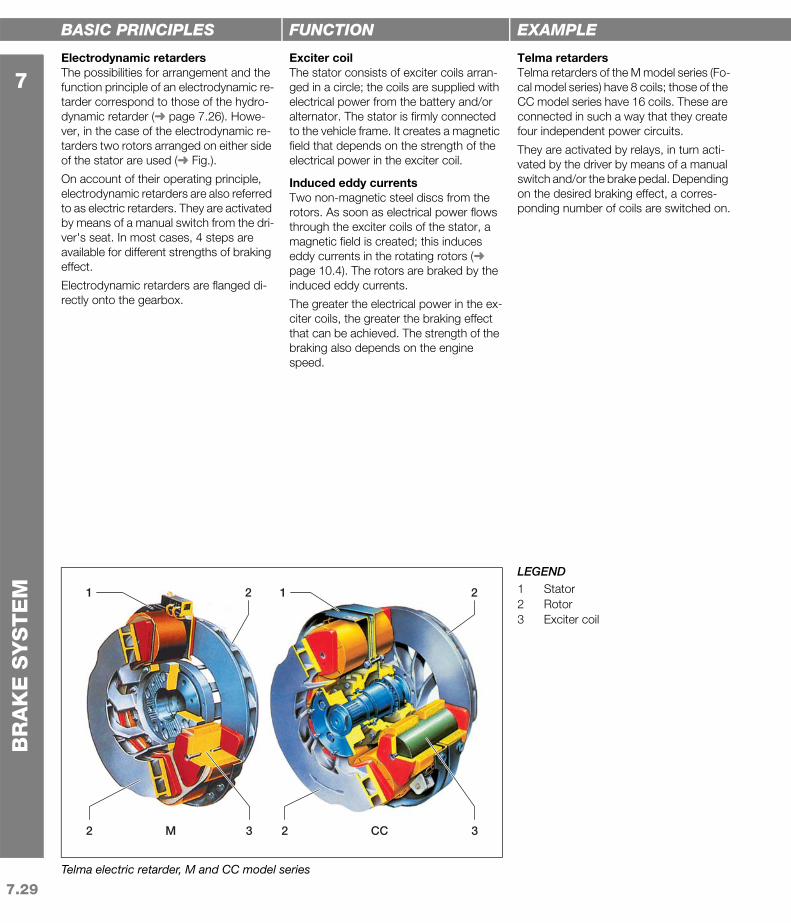
Telma electric retarder, M and CC model series
1
2 3M CC2 3
12 2
LEGEND1 Stator2 Rotor3 Exciter coil
BASIC PRINCIPLES
Electrodynamic retardersThe possibilities for arrangement and the function principle of an electrodynamic re-tarder correspond to those of the hydro-dynamic retarder (➜ page 7.26). Howe-ver, in the case of the electrodynamic re-tarders two rotors arranged on either side of the stator are used (➜ Fig.).
On account of their operating principle, electrodynamic retarders are also referred to as electric retarders. They are activated by means of a manual switch from the dri-ver's seat. In most cases, 4 steps are available for different strengths of braking effect.
Electrodynamic retarders are flanged di-rectly onto the gearbox.
FUNCTION
Exciter coilThe stator consists of exciter coils arran-ged in a circle; the coils are supplied with electrical power from the battery and/or alternator. The stator is firmly connected to the vehicle frame. It creates a magnetic field that depends on the strength of the electrical power in the exciter coil.
Induced eddy currentsTwo non-magnetic steel discs from the rotors. As soon as electrical power flows through the exciter coils of the stator, a magnetic field is created; this induces eddy currents in the rotating rotors (➜ page 10.4). The rotors are braked by the induced eddy currents.
The greater the electrical power in the ex-citer coils, the greater the braking effect that can be achieved. The strength of the braking also depends on the engine speed.
EXAMPLE
Telma retardersTelma retarders of the M model series (Fo-cal model series) have 8 coils; those of the CC model series have 16 coils. These are connected in such a way that they create four independent power circuits.
They are activated by relays, in turn acti-vated by the driver by means of a manual switch and/or the brake pedal. Depending on the desired braking effect, a corres-ponding number of coils are switched on.

7.30
7
BR
AK
E S
YS
TE
M
7.6.
2.4C
ompa
rison
of r
etar
der t
ypes
x
Secondary retarders
00.25 0.5 0.75 1.0
1
2
3
4
5
a
b
MB
MM
nnN
MAN PriTarder and EVBec
012501000 1500 1750
500
1000
1500
2000
2500 c
ed
MB
[Nm]
n [min–1]
LEGENDCurves:a Electrodynamic retarderb Hydrodynamic retarderc MAN PriTarder
(water retarder plus MAN EVBec)d Water retardere MAN EVBecFormula symbols:MB Braking torqueMM Engine torque (maximum)n Engine speednN Rated speed
BASIC PRINCIPLES
Comparison of retarder typesThe main problem with retarder operation is the high level of heat development. In order to prevent damage to the compon-ents through high temperatures, hydraulic retarders and electric retarders are moni-tored electronically.
In the event of excessive temperatures, thermoswitches ensure a limitation of the braking effect. If there is a danger of the wheels blocking, the ABS switched the function of the retarder off.
Below an engine speed of 1000 rpm, con-ventional retarders provide hardly any bra-king power. In order to overcome this de-ficiency, so-called high-drive retarders are used. These are then driven with a gear ratio of 1:2.
FEATURES
Hydrodynamic retardersSpecial features are:
High thermal load due to conversion of the kinetic energy of the drive shaft into heat. In order to be able to remove the braking heat that arises via an oil-water heat exchanger to the engine cooling circuit, the cooling cir-cuit must be large enough.
High construction overhead
Weight saving due to integration in the gearbox (intarder) and thus an incre-ase in economy
High specific braking power as of approx. 1000 rpm
Continuously variable braking power possible (5–6 steps are usual)
This maximum braking torque that can be generated lies in the medium engine speed range. This drops radi-cally at low engine speeds (➜ Fig.).
MAN PriTarderSpecial features are:
Simple water cooling through integra-tion in the cooling circuit; environmen-tally friendly as retarder oil changes and oil disposal are eliminated
High efficiency even at low engine speeds and long period of availability of full braking power
Higher average speed
Significant weight advantage compa-red to secondary retarders
Low sound emission
Higher braking power than compa-rable retarder systems (maximum bra-king power 600 kW)
Electrodynamic retardersSpecial features are:
Dissipation of braking heat that arises to the environment
Relatively low construction overhead
High weight due to exciter coils
Trouble-free operation dependent on adequate power supply
High specific braking power, even at low engine speeds
Significant reduction in braking power due to heating of the rotor
Maximum braking torque that can be generated is available even at low engine speeds; only falls slowly even with higher engine speeds (➜ Fig.)


