
MAN Alpha CP Propeller – Product Information
30
MAN Alpha CP Propeller – Product Information
Transcript of MAN Alpha CP Propeller – Product Information

This Is a HeadlineThis is a subheadlineMAN AlphaCP Propeller – Product Information


Contents
Introduction .................................................................................................5
General Description ......................................................................................5
Propeller equipment ................................................................................5
Propeller type VBS ..................................................................................6
Mechanical Design .......................................................................................9
Hub design .............................................................................................9
ODBox Design .......................................................................................... 10
ODS type ............................................................................................. 10
ODF type .............................................................................................. 11
ODG type ............................................................................................. 11
Servo Oil System ODSODFODG .............................................................. 12
Hydraulic Power Unit (ODS ODF) ........................................................ 12
Hydraulic system, ODG ......................................................................... 13
Lubricating oil system, VBS ................................................................... 13
Propeller Shaft and Coupling Flange ........................................................... 14
Coupling flange ..................................................................................... 14
Stern tube ............................................................................................ 15
Liners ................................................................................................... 15
Seals .................................................................................................... 15
Hydraulic bolts ...................................................................................... 15
Installation ............................................................................................ 15
Propeller Blade Manufacturing and Materials............................................... 16
Blade materials ..................................................................................... 16
Propeller Nozzle ......................................................................................... 17
Nozzle length ........................................................................................ 18
Propeller induced pressure impulses and nozzle vibrations .................... 18
Optimizing Propeller Equipment ................................................................. 19
Propeller design .................................................................................... 19
Optimizing the complete propulsion plant .............................................. 19
Hydrodynamic design of propeller blades .............................................. 20
Cavitation ............................................................................................. 20
High skew ............................................................................................ 21
Technical Calculation and Services ............................................................. 22
Arrangement drawings .......................................................................... 22
Installation Manual ................................................................................ 22
Alignment instructions ........................................................................... 23
Torsional vibrations ............................................................................... 23
Whirling and axial vibration calculations ................................................. 24
Instruction Manual ...................................................................................... 24
Main Dimensions ........................................................................................ 25
Propeller Layout Data ................................................................................. 27

MAN Alpha CP Propeller – Product Information
Introduction
The purpose of this Product Informa
tion brochure is to act as a guide in
the project planning of MAN Diesel &
Turbo´s Alpha propeller equipment.
The brochure gives a description of the
basic design principles of the Alpha
Controllable Pitch (CP) propeller equip
ment. It contains dimensional sketch
es, thereby making it possible to work
out shaft line and engine room arrange
ment drawings. Furthermore, a guide
line to some of the basic layout criteria
is given.
Our design department is available with
assistance for optimization of propul
sion efficiency and propeller interac
tion with the environment it works in.
Prognises are performed on eg speed
and bollard pull, determining power
requirements from the propeller, as well
as advice on more specific questions
like installation aspects and different
modes of operation.
All our product range is constantly un
der review, being developed and im
proved as needs and conditions dic
tate.
We therefore reserve the right to make
changes to the technical specification
and data without prior notice.
In connection with the propeller equip
ment the Alphatronic Control System is
applied. Special literature covering this
field can be forwarded on request.
General Description
MAN Diesel & Turbo have manufac
tured more than 7,000 controllable
pitch propellers of which the first was
produced in 1902.
In 1903 a patent was taken out cov
ering the principle of the CP propeller.
Thus more than a century of experience
is reflected in the design of the present
Alpha propeller equipment.
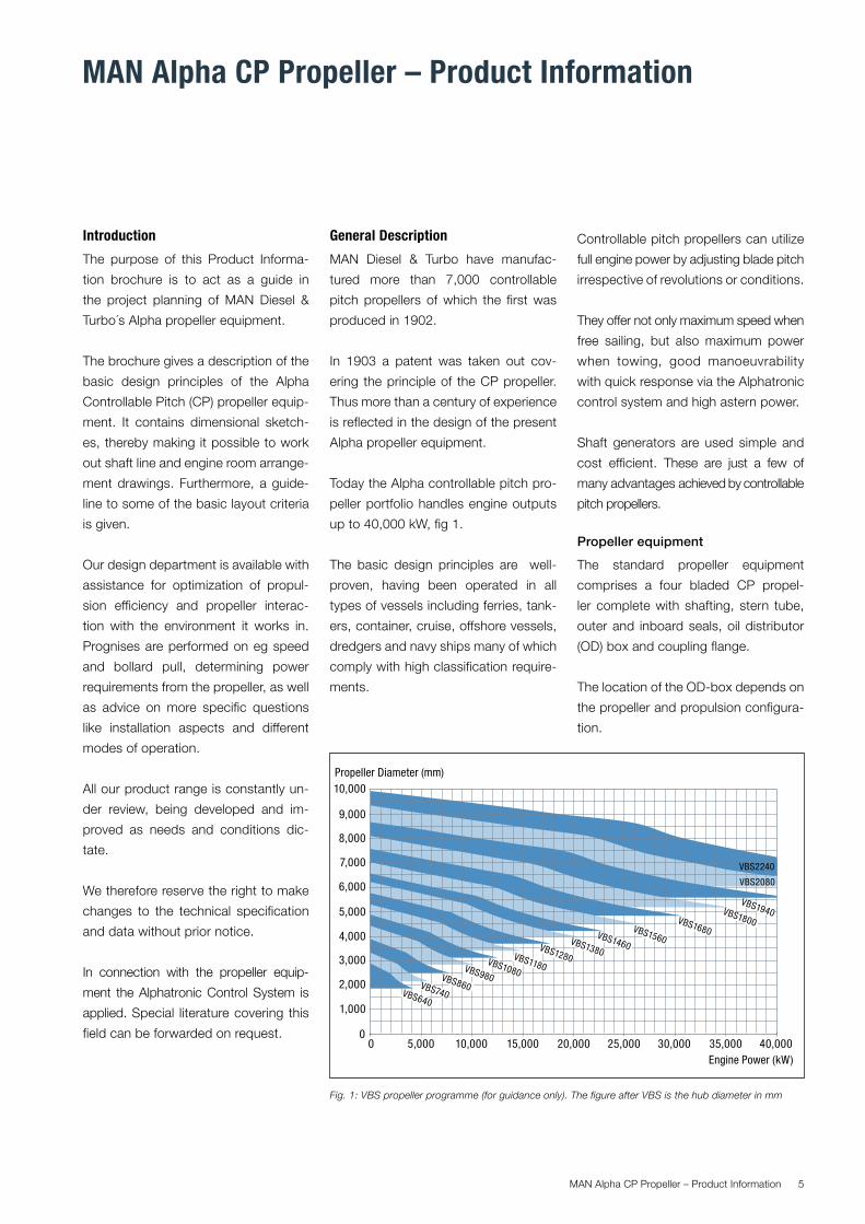
Today the Alpha controllable pitch pro
peller portfolio handles engine outputs
up to 40,000 kW, fig 1.
The basic design principles are well
proven, having been operated in all
types of vessels including ferries, tank
ers, container, cruise, offshore vessels,
dredgers and navy ships many of which
comply with high classification require
ments.
Controllable pitch propellers can utilize
full engine power by adjusting blade pitch
irrespective of revolutions or conditions.
They offer not only maximum speed when
free sailing, but also maximum power
when towing, good manoeuvrability
with quick response via the Alphatronic
control system and high astern power.
Shaft generators are used simple and
cost efficient. These are just a few of
many advantages achieved by controllable
pitch propellers.
Propeller equipment
The standard propeller equipment
comprises a four bladed CP propel
ler complete with shafting, stern tube,
outer and inboard seals, oil distributor
(OD) box and coupling flange.
The location of the ODbox depends on
the propeller and propulsion configura
tion.
Fig. 1: VBS propeller programme (for guidance only). The figure after VBS is the hub diameter in mm
10,000
10,000 15,000 25,000 30,000 35,000 40,00020,000
9,000
8,000
7,000
6,000
5,000
5,000
4,000
3,000
2,000
1,000
00
Propeller Diameter (mm)
Engine Power (kW)
VBS640
VBS740
VBS860
VBS980
VBS1080
VBS1180
VBS1280
VBS1380
VBS1460
VBS1560
VBS1680
VBS1800
VBS1940
VBS2080
VBS2240
MAN Alpha CP Propeller – Product Information 5

Propeller type VBS
The present version of MAN Diesel &
Turbo´s Alpha propeller equipment is
designated VBS. It features an integrat
ed servo motor located in the aft part
of the hub and sturdy designed internal
components.
A welldistributed range of different hub
sizes makes it possible to select an op
timum hub for any given combination of
power, revolutions and ice class. The
different hub sizes are in principle geo
metrical similar and incorporate large
servo piston diameter with low pres
sure and reaction forces and few com
ponents, while still maintaining short
overall installation length.
Oil Distributor box
The VBS propeller equipment can be
supplied with three different oil distri
bution systems for controlling the pitch
depending on the type of propulsion
system i.e. direct driven twostroke or
geared fourstroke. All three types in
corporate the possibility for emergency
operation and a valve box that will keep
the propeller pitch fixed in case the hy
draulic oil supply is interrupted. The lat
ter is required by classification societies
and will prevent the propeller blades
from changing the pitch setting.
ODS Shaft mounted ODbox
For direct driven propellers without re
duction gearboxes the oil distribution
box must be located in the shaft line.
Fig. 3: Propeller equipment type VBS ODS (7S60MCC engine, VBS1800 propeller, frontend PTO stepup gear and alternator)
Fig. 2: Propeller equipment type VBSODG (8L27/38 engine, AMG28EV reduction gear, VBS860 propeller)
MAN Alpha CP Propeller – Product Information6

The ODS type is intended for this type
of installations and features beside the
oil inlet ring a hydraulic coupling flange,
pitch feedback and the valve box. The
unit design ensures short installation
length and all radial holes and slots are
located on the large diameter coupling
flange and are carefully designed to avoid
stress raisers.
ODF Gearbox mounted ODbox
For geared fourstroke propulsion plants
the oil distribution box is usually located
on the forward end of the reduction gear
box.
The ODF contains the same elements
as the ODS type and comes in different
sizes according to the selected type of
VBS propeller equipment.
For long shaft lines with one or more
intermediate shafts it is recommended
to use the ODS type of oil distribution
that will ensure a short feedback sys
tem leading to a more precise control of
the pitch setting.
ODG Gearbox integrated ODbox
For MAN Diesel & Turbo designed
gearboxes (AMG, Alpha Module Gears)
the oil distribution and pitch control
system is an integral part of the gear
box. Apart from the standby pump no
external hydraulic power unit is needed
thus facilitating a simple and space
saving installation.
Fig. 4: Propeller equipment type VBS ODF (6L48/60B engine, reduction gear, VBS1380 propeller)
Fig. 5: Propeller equipment type VBS ODS (8S50MCC engine, Renk tunnel gear, VBS1680 propeller)
MAN Alpha CP Propeller – Product Information 7

Fig. 6: Propeller hub type VBS
MAN Alpha CP Propeller – Product Information8

Mechanical DesignHub design
The hydraulic servo motor for pitch set
ting is an integral part of the propeller
hub. The design is shown in fig 6. The
propeller hub is bolted to the flanged end
of the tailshaft, which is hollow bored to
accommodate the servo oil and pitch
feedback tube. The servo piston which
is bolted to the pitch control head, forms
the hydraulic servo motor together with
the propeller cap.
The high pressure servo oil system at the
aft end of the hub is completely isolated
from the pitch regulating mechanism and
thus also from the blade flanges, which
means that the blade sealings only are
subjected to gravitation oil pressure.
By using a large servo piston diameter
and balanced blade shapes, the oil
pressure and reacting forces are mini
mized.
Blade sealing rings are placed between
blade foot and hub, fig 7. A compressed
Oring presses a PTFE (teflon) slide ring
against the blade foot.
This design ensures maximum reliability
and sealing without leakages, also un
der extreme abrasive wear conditions.
Optionally an intermediate flange can be
inserted, by which underwater replace
ment of propeller blades is possible.
For servicing and inspection of the in
ternal parts, the hub remains attached
to the shaft flange during disassembly
thereby reducing time and need for heavy
lifting equipment. Access to all internal
parts is even possible without disman
tling the propeller blades thus reducing
the time for inspection and mainte
nance during docking.
A hydraulic tube, located inside the
shafting, is connected to the piston. With
hydraulic oil flowing through the tube,
oil is given access into the after section
of the propeller hub cylinder, displacing
the servo piston forward, into an ahead
pitch position. The displaced hydrau
lic oil from forward of the piston is re
turned via the annular space between
the tube and shaft bore to the oil tank.
Reverting the flow directions will move
the propeller in astern position.
Fig. 7: Blade sealing rings
MAN Alpha CP Propeller – Product Information 9

ODBox DesignODS type
The shaft mounted unit, fig. 8, consists
of coupling flange with ODring, valve
box and pitch feedback ring. Via the oil
distribution ring, high pressure oil is
supplied to one side of the servo pis
ton and the other side to the drain.The
piston is hereby moved, setting the de
sired propeller pitch. A feedback ring
is connected to the hydraulic pipe by
slots in the coupling flange. The feed–
back ring actuates one of two displace
ment transmitters in the electrical pitch
feedback box which measures the ac
tual pitch.
The inner surface of the oil distribution
ring is lined with whitemetal. The ring
itself is split for easy exchange without
withdrawal of the shaft or dismounting
of the hydraulic coupling flange.
The sealing consists of mechanical
throw off rings which ensures that no
wear takes place and that sealing rings
of Vlipring type or similar are unnec
essary.
The oil distributor ring is prevented from
rotating by a securing device compris
ing a steel ball located in the ring.
Acceptable installation tolerances are
ensured and movement of the propeller
shaft remains possible.
In the event of failing oil pressure or
fault in the remote control system, spe
cial studs can be screwed into the oil
distribution ring hereby making manual
oil flow control possible. A valve box lo
cated at the end of the shaft ensures
that the propeller pitch is maintained in
case the servo oil supply is interrupted.
Fig. 8: ODS type OD box with coupling flange and pitch feedback ring
Coupling muff OD ring
Hydraulic servo pipe
Valve box
Pitch feed-back ring
Fig. 9: Pitch feedback arrangement and OD ring fixation to ship structure
MAN Alpha CP Propeller – Product Information10

ODF type
The gearbox mounted unit, fig 10, con
sists in principle of the very same me
chanical parts as the ODS type. How
ever, the pitch feedback transmitter is
of the inductive type that operates con
tactless and thus without wear.
The drain oil from the oil distribution is
led back to the hydraulic power unit
tank.
ODG type
The gearboxintegrated unit, fig 11,
consists in principle also of the very
same parts as the ODF type. The main
difference is the use of the gearbox
sump as oil reservoir for both the pro
peller and gearbox. Pitch feed-back
OD boxHydraulic servo pipe
Valve box
Hydraulic servo pipe Pitch feed-back
Fig. 10: ODF type – for gearbox mounting
Fig. 11: ODG type – integrated in MAN Diesel & Turbo´s AMG gearboxes
MAN Alpha CP Propeller – Product Information 11

Servo Oil System ODSODFODG
A servo oil pump delivers high pressure
oil to a highpress filter, a valve unit
consisting of non return valves, safety
valve, pressure adjusting valve and an
electrical operated proportional valve.
This proportional valve, which is used
to control the propeller pitch can also
be manually operated.
From the proportional valve the servo
oil is led to an oil distributor ring. Servo
oil is also used for lubricating and cool
ing of this ring. This excess servo oil is
led back in the servo oil system.
From the oil distributor ring high pres
sure oil is led through pilot operated
double check valves to one or the other
side of the servo piston, until the de
sired propeller pitch has been reached.
The pilot operated double check valves
keep the propeller pitch fixed in case
the servo oil supply is interrupted.
The propeller is equipped with an elec
trical pitch feedback transducer. This
feedback signal is compared to the or
der signal to maintain the desired pitch.
The pitch setting is normally remotely
controlled, but local emergency control
is possible.
Hydraulic Power Unit (ODS ODF)
The hydraulic Power Unit, fig 12, con
sists of an oil tank with all components
top mounted, to facilitate installation at
yard.
Two electrically driven pumps draw oil
from the oil tank through a suction fil
ter and deliver high pressure oil to the
proportional valve through a duplex full Fig. 13: Propeller equipment type VBS ODS
Fig. 12: Hydraulic Power Unit
PD
LAL
TAH
TIPAH
PSL
M M
PSL
PAL PI
PAL
order
M M
Pitch
Drain tankOil Distribution Box type ODS
Stern tubeMonoblock hub
Oil tankforward seal Stern
tube oil tank
Lip ring seals Hydraulicpipe
Propeller shaft
Hydraulic Power Unit
Servopiston
Pitchfeed-back
MAN Alpha CP Propeller – Product Information12

flow pressure filter. One of the 2 pumps
is in service during normal operation.
A sudden change of manoeuvre will
start up the second pump; this second
pump also serves as a standby pump.
A servo oil pressure adjusting valve
ensures minimum servo oil pressure
constantly, except during pitch chang
es, hereby minimizing the electrical
power consumption. Maximum system
pressure is set on the safety valve.
The return oil is led back to the tank
through a cooler and a filter. The servo oil
unit is equipped with alarms according
to the Classification Society as well as
necessary pressure and temperature
indication.
Hydraulic system, ODG
The hydraulic components of the ODG
type are built on the gearbox and the
propeller control valves form together
with the gearbox hydraulics an inte
grated system. The same functions as
described by the ODSODF type are
available with the ODG integrated so
lution the major difference being the
common oil sump for both the propeller
and the gearbox.
In addition to the gearbox driven oil
pump, an electric standby pump will
automatically startup in the event of
missing servo oil pressure.
Lubricating oil system, VBS
The stern tube and hub lubrication is a
common system. The stern tube is kept
under static oil pressure by a stern tube
oil tank placed above sea level, see
fig. 13, 14 and 15.
As an option the propeller can be sup
plied with two separate systems for lu
brication of hub and stern tube.
All Alpha propeller equipment with seals
of the lip ring type operates with lub oil
type SAE 30/40 usually the same type
of lubricating oil as used in the main en
gine and/or reduction gear.
Fig. 14: Propeller equipment type VBS ODF
Fig. 15: Propeller equipment type VBS ODG
TAH
L AL
PD
PAL
P SL
M
T I
M
P SL
PI
PAL
PAH
Pitchorder
Pitchfeed-back
Oil Distribution Box type ODF
Stern tubeMonoblock
hub
Oil tankforward seal Stern
tube oil tank
Lip ring seals
Servopiston Hydraulic
pipe
Propeller shaft
Hydraulic Power Unit
TAH
T I
PSL PSL
M
P AL PI
PAL
PAH
P D
Pitchfeed-back
Oil Distribution Box type ODG
Stern tubeMonoblock
hub
Oil tankforward seal
Sterntube oil tank
Lip ring seals
Servopiston Hydraulic
pipe
Propeller shaft
Hydraulic Power System
Pitchorder
MAN Alpha CP Propeller – Product Information 13

Propeller Shaft and Coupling Flange
The tailshaft is made of normalized and
stress relieved forged steel, table 1.
The tailshaft is hollow bored, housing
the servo oil pipe.
The distance between the aft and for
ward stern tube bearings should gener
ally not exceed 20 times the diameter
of the propeller shaft. If the aft ship de
sign requires longer distances, special
countermeasures may be necessary to
avoid whirling vibration problems.
Coupling flange
The tailshaft can be connected, to the
flywheel directly or to an intermediate
shaft, via a hydraulic coupling flange,
fig 16. To fit the flange high pressure oil
of more than 2,000 bar is injected be
tween the muff and the coupling flange
by means of the injectors in order to ex
pand the muff.
By increasing the pressure in the annu
lar space C, with the hydraulic pump,
the muff is gradually pushed up the
cone. Longitudinal placing of the cou
pling flange as well as final pushup of
the muff are marked on the shaft and
the muff.
Epoxy resin
Stern tube
Boss Welding ring
Injectors
Venting100
Mark onshaft
Hydraulic pump
A
C
Measurement for push-up stampedon the coupling muff
Installationdimension
Fig. 16: Shrink fitted coupling flange
Fig. 17: Standard stern tube – VBS
C
Material
Forged
steel type
S45P
Yield strength N/mm² minimum
350
Tensile strength N/mm²
minimum
600
Elongation % minimum 18
Impact strength
Charpy Vnotch
J
minimum 18
Table 1
MAN Alpha CP Propeller – Product Information14

Stern tube
Many different installation and stern
tube alternatives exist for both oil and
water lubrication. The standard stern
tube is designed to be fitted from aft
and installed with epoxy resin and bolt
ed to the stern frame boss, fig 17.
The forward end of the stern tube is
supported by the welding ring.
The oilbox and the forward shaft seal
are bolted onto the welding ring. This
design allows thermal expansion/con
traction of the stern tube and decreas
es the necessity for close tolerances of
the stern tube installation length.
As an option the stern tube can be in
stalled with a pressfitting and bolted to
the stern frame boss. The stern tube is
then supplied with 5 mm machining al
lowance for yard finishing.
Liners
The stern tube is provided with forward
and aft white metal liners, fig 18. Sen
sors for bearing temperature can be
mounted, if required. A thermometer for
the forward bearing is standard.
Seals
As standard, the stern tube is provided
with forward and after stern tube seals
of the lip ring type having three lip rings
in the after seal and two lip rings in the
forward seal, fig 19.
Hydraulic bolts
The propeller equipment can be sup
plied with hydraulic fitted bolts for easy
assembly and disassembly, fig 20. Ma
chining of holes is simple, reaming or
honing is avoided.
Installation
Installation of propeller equipment into
the ship hull can be done in many dif
ferent ways as both yards and own
ers have different requirements of how
to install and how to run the propeller
equipment. Other designs of stern tube
and/or shaft sealings may be preferred.
MAN Diesel & Turbo are available with
alternatives to meet specific wishes or
design requirements.
Fig. 20: Hydraulic fitted bolt
Fig. 19: Stern tube seals
Cast-Iron Lead-based white metal
Fig. 18: Stern tube white metal liner
MAN Alpha CP Propeller – Product Information 15

Propeller Blade Manufacturing and Materials
The international standard organization
has introduced a series of manufactur
ing standards in compliance with which
propellers have to be manufactured
(ISO 484). The accuracy class is normally
selected by the customer and the table
below describes the range of manufac
turing categories.
If no Class is specified, the propeller
blades will be manufactured according
to Class I but with surface roughness
according to Class S.
Blade materials
Propeller blades are made of either
NiAl–bronze (NiAl) or stainless steel
(CrNi). The mechanical properties of
each material at room temperature are:
Both materials have high resistance
against cavitation erosion. The fatigue
characteristics in a corrosive environ
ment are better for NiAl than for CrNi.
Propeller blades are, to a large degree,
exposed to cyclically varying stresses.
Consequently, the fatique material
strength is of decisive importance.
The dimensioning of a propeller blade
according to the Classification Socie
ties will give a 10% higher thickness for
the CrNi compared to NiAl in order to
obtain the same fatigue strength.
As an example the thickness and weight
difference for a propeller blade for a
mediumsize propulsion system (4,200
kW at 170 r/min) is stated in table 2.
CrNisteel requires thicker blades than
NiAlbronze, which is unfortunate from
the propeller theoretical point of view (thick
er = less efficiency). Additionally, the CrNi
is more difficult to machine than NiAl.
For operation in ice the CrNi material
will be able to withstand a higher force
before bending due to its higher yield
strength and for prolonged operations
in shallow water the higher hardness
makes it more resistant to abrasive
wear from sand.
The final selection of blade and hub
material depends on owners require
ments and the operating condition of
the vessel. In general terms the NiAl
material is preferable for ordinary
purposes whereas CrNi could be an
attractive alternative for nonducted
Class Manufacturing accuracy
S Very high accuracy
I High accuracy
II Medium accuracy
III Wide tolerances
Material NiAl CrNi
Yield strength
N/mm²
min 250
min 380
Tensile strength
N/mm²
min 630
660790
Elongation % min 16 min 19
Impact strength Kv at 10 °C
Joules
21
21
BrinellHardness
HB
min 140
240300
Table 2: Classification Society: Det Norske Veritas
Ice class C 1A*
Material NiAl CrNi NiAl CrNi
Thickness at r/R = 0.35 mm 132 146 169 187
Thickness at r/R = 0.60 mm 71 78 90 100
Thickness at r/R = 1.00 mm 0 0 15 13
Blade weight kg 729 877 952 1053
Fig. 21: Optimum propeller diameter
9000
1000
2000
3000
4000
5000
6000
7000
Engine power kW
75
100
125
150
175200
250
300350400
Propeller diameter mmr/min
1500013000110001000 3000 5000 7000
MAN Alpha CP Propeller – Product Information16

propellers operating in heavy ice or
dredgers and vessels operating in
shallow waters.
Propeller Nozzle
Typical offshore vessels, tugs and trawl
ers are equipped with nozzles around
their propellers to increase the bollard
pull and the pull at low ship speeds.
Maximising the bollard pull has up to
now primarily been a matter of having
sufficient power installed with little at
tention paid to the efficiency of the pro
pulsion system in particular the propel
ler and its nozzle.
Especially the nozzle ‘type 19A’ de
veloped by Wageningen model basin
in the Nederlands has for many years
been universally used for all sorts of
vessels, partly due to its production
friendly design. To less extent the ‘type
37’ nozzle is used, normally where high
astern thrust is required.
MAN Diesel & Turbo, however, has seen
the potential for improving the existing
nozzle designs, using CFD (Compu
tational Fluid Dynamics) and including
optimization of the nozzle supports and
nozzle position by tilting and azimuth
ing.
The newly designed nozzle branded
AHT (Alpha High Thrust) can in com
bination with the optimum choice of
support and tilting angels increase the
bollard pull by up to 10% compared to
a ‘type 19A’ nozzle with conventional
head box support. See Fig. 23.
The improvements can be obtained if
the propulsion system is optimised in
conjunction with the hull and shaft line.
Fig. 22: CFD calculation of propeller and nozzle
Fixation Fig CC. Calculation of nozzle vibrations
Wageningen 19A New MAN Diesel AHT Design
Fig. 23: Comparison between 19A and AHT propeller nozzle profile
MAN Alpha CP Propeller – Product Information 17

Nozzle length
The fixed nozzles are typically supplied
in two standard lengths, either 0.4 or
0.5 x propeller diameter, according to
the application.
For low loaded propellers a length of
0.4 x propeller diameter is used and
for higher loaded propellers and fluc
tuations in the wake field it is recom
mendable to use a nozzle length of 0.5
x propeller diameter.
In special cases the propeller nozzle
length may be optimized for the spe
cific vessel.
Propeller induced pressure impulses
and nozzle vibrations
Since the propeller nozzle has an equal
izing effect on the wake field around
the propeller, the nozzle has a favour
able influence on the propeller induced
pressure impulses.
Additionally ducted propellers are lower
loaded than open propellers contribut
ing to a lower vibration level.
MAN Diesel & Turbo can carry out vibration
analysis of the propeller nozzle with sup
ports to ensure that the natural frequency
of the nozzle and excitations from the pro
peller does not coincide, fig 25.
Fig. 25: Calculation of nozzle vibrations
Fig. 24: CFD calculation pressure and velocity, nozzle 19A (left) and AHT (right)
MAN Alpha CP Propeller – Product Information18

Optimizing Propeller Equipment Propeller design
The design of a propeller for a vessel
can be categorized in two parts:
� Optimizing the complete propulsion
plant
� Hydrodynamic design of propeller
blades
Optimizing the complete propulsion
plant
The design of the propeller, giving regard
to the main variables such as diameter,
speed, area ratio etc, is determined by
the requirements for maximum efficiency
and minimum vibrations and noise levels.
The chosen diameter should be as large
as the hull can accommodate, allowing
the propeller speed to be selected ac
cording to optimum efficiency.
The optimum propeller speed corre
sponding to the chosen diameter can
be found in fig 18 for a given reference
condition (ship speed 12 knots and
wake fraction 0.25).
For ships often sailing in ballast condi
tion, demands of fully immersed propel
lers may cause limitations in propeller
diameter. This aspect must be consid
ered in each individual case.
To reduce emitted pressure impulses
and vibrations from the propeller to the
hull, MAN Diesel & Turbo recommend a
minimum tip clearance as shown in fig 26.
The lower values can be used for ships
with slender aft body and favourable in
flow conditions whereas full after body
ships with large variations in wake field
require the upper values to be used.
In twin screw ships the blade tip may
protrude below the base line.
The operating data for the vessel is
essential for optimizing the propeller
successfully, therefore it is of great im
portance that such information is avail
able.
To ensure that all necessary data are
known by the propeller designer, the
data sheets on page 25 and 26, should
be completed.
For propellers operating under varying
conditions (service, max or emergen
cy speeds, alternator engaged/disen
gaged) the operating time spent in each
mode should be given.
This will provide the propeller designer
with the information necessary to deFig.26: Recommended tip clearance
Hub
Dismantling
of cap
X mm
High skew
propeller
Y mm
Non–skew
propeller
y mm
Baseline
clearance
Z mm
VBS 640 125
VBS 740 225
VBS 860 265
VBS 980 300
VBS 1080 330
VBS 1180 365
VBS 1280 395
VBS 1380 420 20–25% of D 25–30% of D Minimum 50–100
VBS 1460 450
VBS 1560 480
VBS 1680 515
VBS 1800 555
VBS 1940 590
VBS 2080 635
VBS 2240 680
MAN Alpha CP Propeller – Product Information 19

sign a propeller capable of delivering
the highest overall efficiency.
To assist a customer in selecting the op
timum propulsion system, MAN Diesel
& Turbo are able of performing speed
prognosis, fig 27, fuel oil consumption
calculations, fig 28, and towing force
calculations fig 29. Various additional
alternatives may also be investigated
(ie different gearboxes, propeller equip
ment, nozzles against free running pro
pellers, varying draft and trim of vessel,
etc). Additionally we can assist in the
hydrodynamic design of aft ship, shaft
and brackets arrangement in order to
achieve a uniform inflow to the propel
ler. In connection with the Alpha pro
peller, a number of efficiency improving
devices have been tested and applied
comprising Costa bulbs, tip fin propel
lers, vortex generators, wake equalizing
ducts etc. The experience gained in this
respect is available for future projects
where such devices are considered.
Hydrodynamic design of propeller
blades
The propeller blades are computer de
signed, based on advanced hydrody
namic theories, practical experience
and frequent model tests at various
hydrodynamic institutes.
The blades are designed specially for
each hull and according to the operat
ing conditions of the vessel.
High propulsion efficiency, suppressed
noise levels and vibration behaviour are
the prime design objectives.
Propeller efficiency is mainly deter
mined by diameter and the correspond
ing optimum speed. To a lesser, but still
important degree, the blade area, the
pitch and thickness distribution also
have an affect on the overall efficiency.
Blade area is selected according to
requirements for minimum cavitation,
noise and vibration levels.
To reduce the extent of cavitation on
the blades even further, the pitch distri
bution is often reduced at the hub and
tip, fig 30. Care must be taken not to
make excessive pitch reduction, which
will effect the efficiency.
Thickness distribution is chosen ac
cording to the requirements of the
Classification Societies for unskewed
propellers and complemented by a fi
nite element analysis.
Cavitation
Cavitation is associated with genera
tion of bubbles caused by a decrease in
Fig. 31: Suction side (sheet cavitation)
Fig. 32: Suction side (bubble cavitation
Fig. 33: Pressure side (sheet cavitation)
V
V
αV
α
0
2000
4000
6000
8000
8
Power (kW)
Speed (knots)1610 12 14
Fig. 27: Speed prognosis
Fig. 28: Fuel oil consumption
Fig. 29: Tow force
Fig. 30: Pitch distribution along radius
Consumption (kg/hour)
0
400
800
1200
1600
16Speed (knots)
8 10 12 14
6400
440
480
520
560
600
Tow force (kN)
Speed (knots)0 1 2 3 4 5
0,60
0,80
1,00
1,20
1,40Pitch/diameter ratio
0,80 1,00Dimensionless ratio of radii r/R
0,40 0,60
MAN Alpha CP Propeller – Product Information20

the local pressure below the prevailing
saturation pressure. The low pressure
can be located at different positions on
the blade as well as in the trailing wake.
When water passes the surface of the
propeller it will experience areas where
the pressure is below the saturation
pressure eventually leading to genera
tion of air bubbles. Further down stream
the bubbles will enter a high pressure
region where the bubbles will collapse
and cause noise and vibrations to oc
cur, in particular if the collapse of bub
bles takes place on the hull surface.
Three main types of cavitation exist
their nature and position on the blades
can be characterized as:
Sheet cavitation on suction side
The sheet cavitation is generated at
the leading edge due to a low pressure
peak in this region. If the extent of cavi
tation is limited and the clearance to the
hull is sufficient, no severe noise/vibra
tion will occur. In case the cavitation
extends to more than half of the chord
length, it might develop into cloud cavi
tation.
Cloud cavitation often leads to cavita
tion erosion of the blade and should
therefore be avoided. Sheet cavitation
in the tip region can develop into a tip
vortex which will travel down stream. If
the tip vortex extends to the rudder, it
may cause erosion, fig. 31.
Bubble cavitation
In case the propeller is overloaded ie
the blade area is too small compared
to the thrust required the mid chord
area will be covered by cavitation. This
type of cavitation is generally followed
by cloud cavitation which may lead to
erosion. Due to this it must be avoided
in the design, fig. 32.
Sheet cavitation on pressure side
This type of cavitation is of the same
type as the suction side sheet cavita
tion but the generated bubbles have
a tendency to collapse on the blade
surface before leaving the trailing edge.
The danger of erosion is eminent and
the blade should therefore be designed
without any pressure side cavitation,
fig. 33.
By using advanced computer pro
grammes the propeller designs will be
checked for the above cavitation types
and designed to minimize the extent of
cavitation as well as to avoid harmful
cavitation erosion.
For each condition and all angular po
sitions behind the actual hull, the flow
around the blade is calculated. The extent
of cavitation is evaluated with respect to
noise and vibration, fig 34.
High skew
To suppress cavitation induced pres
sure impulses even further, a high skew
blade design can be applied, fig 35.
By skewing the blade it is possible to
reduce the vibration level to less than
30% of an unskewed design. Because
skew does not affect the propeller ef
ficiency, it is almost standard design on
vessels where low vibration levels are
required.
Today, the skew distribution is of the
“balanced” type, which means that
the blade chords at the inner radii are
skewed (moved) forward, while at the
outer radii the cords are skewed aft. By
designing blades with this kind of skew
distribution, it is possible to control the
spindle torque and thereby minimize
the force on the actuating mechanism
inside the propeller hub, fig 36.
r/R
4
2
0
-2
-4
Pressure-2
-4
0
0.80.6 1.0
Angle of attack (degrees)
2
4Suction
Actual
0.80 1.00r/R0.40 0.60
0.4
Fig. 34: Cavitation chart and extension of sheet cavitation suction side
Fig. 35: High skew design
Skew angle
Centre line shaft
MAN Alpha CP Propeller – Product Information 21

The extent of skew is calculated in each
case, by rotating the blade in the spe
cific wake field, for determinig the opti
mum skew.
For high skew designs, the normal sim
ple beam theory does not apply and
a more detailed finite element analysis
must be carried out, fig 37.
Technical Calculation and ServicesArrangement drawings
Provided MAN Diesel & Turbo have ad
equate information on the ship hull, an
arrangement drawing showing a suit
able location of the propulsion plant in
the ship can be carried out with due
consideration to a rational layout of
propeller shaft line and bearings.
In order to carry out the above arrange
ment drawing MAN Diesel & Turbo
need the following drawings:
Ship lines plan
Engine room arrangement
General arrangement
Moreover, to assist the consulting firm
or shipyard in accomplishing their own
arrangement drawings, drawings of
our propeller programme can be for
warded. The disks are compatible with
various CAD programmes. Should you
require further information, please con
tact us.
Installation Manual
After the contract documentation has
been completed an Installation Manu
al will be forwarded. As an option the
manual will be available in electronic
format via our ExtraNet offering you the
advantage of easy and fast access to
the documentation. When the docu
mentation is released your user name
and password for access to your per
sonal folder will be forwarded by sepa
rate email.
The Installation Manual will comprise all
necessary detailed drawings, specifi
cations and installation instructions for
our scope of supply. The manual is in
English language.
Fig. 37: Finite element calculation of propeller blade
Fig. 36: Spindle torque
4
2
0
Spindle torque (kNm)
180
Single blade
360Angle (degrees)
Allle blades
0 90
MAN Alpha CP Propeller – Product Information22

CAE programmes are used for making
alignment calculations, epoxy chock
calculations, torsional vibration calcula
tions etc. In the following a brief de
scription is given of some of our CAE
programmes and software service.
Alignment instructions
For easy alignment of the propeller
shaft line, alignment calculations are
made and a drawing with instructions
is given in the Installation Manual, fig 38.
The alignment calculations ensure ac
ceptable load distribution of the stern
tube bearings and shaft bearings.
Torsional vibrations
A comprehensive analysis of the tor
sional vibration characteristics of the
complete propulsion plant is essential
to avoid damage to the shafting due to
fatigue failures.
Based on vast experience with torsion
al vibration analysis of MAN B&W two
stroke and MAN fourstroke propulsion
plants, the VBS propeller equipment is
designed with optimum safety against
failure due to fatigue. Stress raisers in
the shafting or servo unit are minimized
using finite element calculation tech
niques.
When the propeller is delivered with a
MAN or MAN B&W engine a complete
torsional vibration analysis in accor
dance with the Classification Society
rules is performed. This includes all
modes of operation including simula
tion of engine misfiring.
When the total propulsion plant is
designed by MAN Diesel & Turbo, the
optimum correlation between the in
dividual items exists. The extensive
Fig. 38: Calculated reactions and deflections in bearings
Fig. 39: Torsional vibration calculation
Torsional stress amplitude (N/mm2)150
100
50
040 50 60 70 80 90 100 110 120 130 150
Engine speed r/min
Rule limit fortransient running
Rule limit forcontinuous running
Actual stresses Barred speed range
Bearing
Bearing
reaction
[kN]
Vertical
displacement
[mm]
Angular
deflection
[mRad]
Aft sterntube bearing 51.55 0.00 0.476
Fwd sterntube bearing 22.81 0.00 0.221
Aft main gear bearing 15.67 0.70 0.007
Fwd main gear bearing 15.16 0.70 0.003
MAN Alpha CP Propeller – Product Information 23

knowhow ensures that the optimum
solution is found as regards minimiz
ing stresses in connection with tor
sional vibration calculations. Fig 39
shows the result of a torsional vibration
calculation.
When propellers are supplied to anoth
er engine make, a complete set of data
necessary for performing the analysis
is forwarded to the engine builder in
question, fig 40.
Whirling and axial vibration calcula
tions
Based on our experience the propeller
equipment and shafting are designed
considering a large safety margin against
propeller induced whirl and axial vibra
tions. In case of plants with long inter
mediate shafting or stern posts carried
by struts, a whirling analysis is made to
ensure that the natural frequencies of
the system are sufficiently outside the
operating speed regime.
Propeller induced axial vibrations are
generally of no concern but analysis of
shafting systems can be carried out in
accordance with Classification Society
requirements.
Instruction Manual
As part of our technical documentation,
an Instruction Manual will be forwarded.
The Instruction Manual is tailormade
for each individual propeller plant and
includes:
Descriptions and technical data
Operation and maintenance guide
lines
Work Cards
Spare parts plates
As standard the manual is supplied in
a printed version, and can as an option
be forwarded in electronic document
format.
Fig. 40: Propeller data for torsional vibration analysis
SP E C .F ILLE T
R 200 R 200
SP
E C. F
ILLE
T
K3
4037754110
46511003785 943950K2
11 97
110
110
R 100
R 200
2000K1
R 200 R 200
Ø570
/Ø18
0
600
150
5476W-MEASURE = 3700S-MEASURE = 5 98011551175
Ø560
/Ø18
0
Ø565
/Ø18
0
Ø555
/Ø18
0
Ø740
/Ø56
0
Ø510
Ø520
Ø510
Propeller data
Inertia in air
kgm²
32900
Inertia in water (full pitch) kgm² 39300
Inertia in water (zero pitch) kgm² 34500
Number of blades 4
Propeller diameter mm 6100
Design pitch 0.755
Expanded area ratio 0.48
Propeller weight (hub + blades) kg 22230
Shaft data
Shaft section Material Tensile strength
N/mm²
Yield strength
N/mm²
Torsional stiff
ness MNm/rad
Propeller shaft Forged steel min 600 min 350 K1 99.0
Servo unit Forged steel min 740 min 375 K2 1105.0
Intermediate shaft Forged steel min 600 min 350 K3 105.6
MAN Alpha CP Propeller – Product Information24

Main Dimensions W-minimum- ODF/ODG
W-minimum- ODs
AB
Gearbox F
L M IS
I
640 270 180 500 330 491 604 1316 780
640 270 200 500 355 491 604 1316 780
640 270 225 500 380 491 604 2096 1331 780
740 307 200 580 355 569 661 2096 1316 780
740 307 225 580 385 569 661 2096 1331 780
740 307 250 580 415 569 661 2231 1401 780
740 307 280 580 420 569 681 2352 1522 780
860 364 225 670 385 653 722 2096 1331 780
860 364 250 670 415 653 722 2231 1401 780
860 364 280 670 455 653 742 2352 1522 780
860 364 310 670 475 653 747 2367 1557 780
860 364 330 670 475 653 747 2482 1629 780
980 416 250 760 435 746 794 2231 1401 780
980 416 280 760 475 746 814 2352 1522 780
980 416 310 760 510 746 819 2367 1557 780
980 416 330 760 535 746 844 2482 1629 780
980 416 350 760 550 746 844 2503 1650 780
980 416 375 760 550 746 844 2578 1698 780
1080 458 280 840 475 821 890 2352 1522 820
1080 458 310 840 510 821 895 2367 1557 820
1080 458 330 840 535 821 920 2482 1629 820
1080 458 350 840 560 821 920 2503 1650 820
1080 458 375 840 590 821 920 2578 1698 820
1080 458 400 840 590 821 920 2518 1738 820
1180 502 310 915 530 885 947 2367 1557 820
1180 502 330 915 555 885 972 2482 1629 820
1180 502 350 915 580 885 972 2503 1650 820
1180 502 375 915 610 885 972 2578 1698 820
1180 502 400 915 640 885 972 2518 1738 820
1180 502 425 915 655 885 972 2648 1778 820
1180 502 450 915 655 885 972 2691 1831 820
HUB Max shaft ODS/ A * B L **M * Wmin * Wmin ***F
VBS Diameter ODG ODS ODG ODF
Type [mm] Type [mm] [mm] [mm] [mm] [mm] [mm] [mm]
MAN Alpha CP Propeller – Product Information 25

1280 560 350 1000 580 957 1025 2503 1650 910
1280 560 375 1000 610 957 1025 2578 1698 910
1280 560 400 1000 640 957 1025 2518 1738 910
1280 560 425 1000 670 957 1050 2648 1778 910
1280 560 450 1000 700 957 1050 2691 1831 910
1280 560 475 1000 710 957 1050 2701 1881 910
1380 578 375 1070 610 1030 1081 2578 1698 910
1380 578 400 1070 640 1030 1081 2518 1738 910
1380 578 425 1070 670 1030 1096 2648 1778 910
1380 578 450 1070 700 1030 1096 2691 1831 910
1380 578 475 1070 730 1030 1101 2701 1881 910
1380 578 510 1070 730 1030 1101 2923 1913 910
1460 612 400 1130 650 1100 1121 2518 1738 910
1460 612 425 1130 680 1100 1136 2648 1778 910
1460 612 450 1130 710 1100 1136 2691 1831 910
1460 612 475 1130 740 1100 1141 2701 1881 910
1460 612 510 1130 775 1100 1141 2923 1913 910
1460 612 560 1130 775 1100 1141 3001 1966 910
1560 650 425 1210 680 1175 1197 2648 1778 1000
1560 650 450 1210 710 1175 1197 2691 1831 1000
1560 650 475 1210 740 1175 1202 2701 1881 1000
1560 650 510 1210 785 1175 1202 2923 1913 1000
1560 650 560 1210 810 1175 1237 3001 1966 1000
1560 650 600 1210 810 1175 1237 3101 2051 1000
1680 727 450 1295 720 1278 1274 2691 1831 1000
1680 727 475 1295 750 1278 1279 2701 1881 1000
1680 727 510 1295 795 1278 1279 2923 1913 1000
1680 727 560 1295 855 1278 1314 3001 1966 1000
1680 727 600 1295 900 1278 1344 3101 2051 1000
1800 764 510 1390 795 1367 1332 2923 1913 1120
1800 764 560 1390 855 1367 1367 3001 1966 1120
1800 764 600 1390 905 1367 1397 3101 2051 1120
1940 826 510 1500 805 1458 1412 2923 1913 1120
1940 826 560 1500 865 1458 1447 3001 1966 1120
1940 826 600 1500 915 1458 1477 3101 2051 1120
* Guiding approx dimensions, **Mmeasure for standard shaft seals, ***Fmeasure is minimal required space for dismantling
HUB Max shaft ODS/ A * B L **M * Wmin * Wmin ***F
VBS Diameter ODG ODS ODG ODF
Type [mm] Type [mm] [mm] [mm] [mm] [mm] [mm] [mm]
MAN Alpha CP Propeller – Product Information26

Propeller Layout Data
Project : _________________________ Type of vessel : _______________________
For propeller layout please provide the following information:
1. S : ________ mm W : ________ mm I : ________ mm (as shown above)
2. Stern tube and shafting arrangement layout
3. Stern tube mountings: Expoxy mounted or interference fitted
4. Propeller aperture drawing
5. Copies of complete set of reports from model tank test (resistance test, selfpropulsion test and
wake measurement). In case model test is not available section 10 must be filled in.
6. Drawing of lines plan
7. Classification society : _____________ Notation:___________Ice class notation :______________
8. Maximum rated power of shaft generator : __________ kW
9. To obtain the highest propeller efficiency please identify the most common service condition for the vessel:
Ship speed : __________ kn Engine service load : __________ %
Service/sea margin : __________ % Shaft gen. service load : __________ kW
Draft : __________ m
A B
GearboxW-minimum-ODF/ODG
W-minimum-ODSL M IS
I
MAN Alpha CP Propeller – Product Information 27

10. Vessel Main Dimensions (Please fillin if model test is not available)
Nom Dim Ballast Loaded
Length between perpendiculars LPP m
Length of load water line LWL m
Breadth B m
Draft at forward perpendicular TF m
Draft at aft perpendicular TA m
Displacement Ñ m3
Block coefficient (LPP) CB
Midship coefficient CM
Waterplane area coefficient CWL
Wetted surface with appendages S m2
Centre of buoyancy forward of LPP/2 LCB m
Propeller centre height above baseline H m
Bulb section area at forward perpendicular AB m2
11. Comments : _______________________________________________________
_________________________________________________________________
_________________________________________________________________
_________________________________________________________________
Date:_________________________ Signature:___________________________
MAN Alpha CP Propeller – Product Information28

MAN Alpha CP Propeller – Product Information 29

All data provided in this document is nonbinding. This data serves informational purposes only and is especially not guaranteed in any way. Depending on the subsequent specific individual projects, the relevant data may be subject to changes and will be assessed and determined individually for each project. This will depend on the particular characteristics of each individual project, especially specific site and operational conditions. Copyright © MAN Diesel & Turbo. 5510010101ppr Jan 2013 Printed in Denmark
MAN Diesel & TurboNiels Juels Vej 15DK9900 Frederikshavn, DenmarkPhone +45 96 20 41 00Fax +45 96 20 40 30infofrh@mandieselturbo.comwww.mandieselturbo.comwww.manalpha.com
MAN Diesel & Turbo – a member of the MAN Group