Making Connections: Navigating Fiber Optic Cabling and ......Making Connections: Navigating Fiber...
35
MPS Webinar Technical Series microwave photonic systems ಯExpand Your RF Horizonsರ Making Connections: Navigating Fiber Optic Cabling and Interconnection Requirements
Transcript of Making Connections: Navigating Fiber Optic Cabling and ......Making Connections: Navigating Fiber...

MPS Webinar Technical Series
microwave photonic systems
Expand Your RF Horizons
Making Connections: Navigating Fiber Optic
Cabling and Interconnection Requirements

Introduction – Microwave Photonic Systems
Microwave Photonic Systems, Inc. is a full service design and integration engineering firm, that
specializes in the development and manufacture of RF/Microwave and fiber optic components,
cable assemblies, modules and systems.
Microwave Photonic Systems, Inc. provides products and services to a wide array of military and
commercial customers, who operate in the Broadband, Defense, Telecommunications, SATCOM, and
Wireless markets.
Microwave Photonic Systems, Inc. was incorporated supporting the RF Optical Market since 1999

Purpose – Fiber Optic Cabling and Interconnection Fundamentals
• Provide Basic Education on Fiber Optic Technology
• Review Optical Cable and Connector Types
• Define Key Terms used in the Fiber Conversation
• Discuss Measurement and Analysis Techniques / Standards
• Emphasize Importance of Connector End-face Geometry and Cleanliness
• Equip Project Stakeholders with Knowledge to Make Performance & Cost-Wise Decisions

Where is fiber? • Anywhere data can be transported
• Data Centers / Cloud Computing / CCTV Networks
• Fiber to the X (FTTX) Applications such as Cable Television – FTTH (Fiber to the Home), FTTC (Fiber to the Classroom),
• Industrial Oil, Mining and Gas
• Satellite Communications & Earth Terminals
• Signal Repeaters for Railways, Subways, Tunnels
• Metro Area Networks, Public Wi-Fi, CCTV Networks
• In-Building Distributed Antenna Systems
• Commercial Broadcast & Entertainment

Why use fiber?
• Data carrying capacity much greater than copper
• Loss over distance much less than coax cables
• Uniform loss over frequency (RF over Fiber Applications)
• Scalable solutions from low to high density
• Lightweight, Easy to Install, Long Lasting
• Immunity to Lightning Strikes & RF Interference
• Mature and robust technology readily available

Basic Fiber Optic Communication System
• Digital Data – Ones & Zero's – Ethernet over Fiber
• Analog Signals – Amplitude Modulated - RF over Fiber
FIBER OPTIC
TRANSMITTER
1 0 1 0 1 0 1 0 1
FIBER OPTIC
RECEIVER
1 0 1 0 1 0 1 0 1
ON ON ON ON ON
OFF OFF OFF OFF
FIBER OPTIC
TRANSMITTER
FIBER OPTIC
RECEIVER
RF INPUT RF OUTPUT

Types of Optical Sources and Optical Detectors
• Different Sources for Different Applications
• Optical Source May Vary From One Network to Another
• Knowing The Device Helps Select Proper Optical Cable

Optical Fiber & Cable Construction
• Many different vendors with many different variations
• Only a few key glass manufacturers
• Corning, Alcoa Fujikura Ltd (AFL)
• All others specialize in making the cables
• Jacketing, Coloring, Armoring
• Design trade-offs exists across all variants
• Single Fiber, Multi-Fiber, Distribution vs Breakout, Ribbonized

Multimode Fiber
Multimode Fiber: -Larger Core
- Shorter Distances/ Lower Bandwidth
- Graded-Index / Step Index
- More Common in Legacy Systems

Why Singlemode over Multimode? • Modes can take different paths within Multi-Mode Fiber
• Different paths = different transit times between TX and RX
• Modes that take the high angle path arrive later those of
the low angle path.
• Different transit times cause Dispersion of the optical
signal
• Dispersion causes pulse spreading
• Pulse Spreading Limits Available Bandwidth. Note: This is
true for both digital and analog transmission distances
• Dispersion limits the bandwidth of multimode fiber to 1
GHz/km

Single Mode Fiber
Singlemode Fiber: - Smaller Core
- Longer Distances
- Greater Bandwidth
- Most commonly used today

Visually Identifying Optical Cables

Useful Quick Reference Tables

Connectors for Any Application
Many different vendors – Common Standards
Design trade-offs exists across all variants
Vendor base has various quality levels
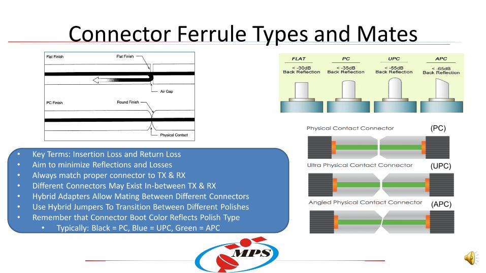
Connector Ferrule Types and Mates
• Key Terms: Insertion Loss and Return Loss
• Aim to minimize Reflections and Losses
• Always match proper connector to TX & RX
• Different Connectors May Exist In-between TX & RX
• Hybrid Adapters Allow Mating Between Different Connectors
• Use Hybrid Jumpers To Transition Between Different Polishes
• Remember that Connector Boot Color Reflects Polish Type
• Typically: Black = PC, Blue = UPC, Green = APC
(PC)
(UPC)
(APC)

Basic Connector Process • Strip and Prep Cable
• Epoxy Connector
• Insert Fiber into Connector
• Crimp Assembly
• Oven Cure
• Polish
• Test

Polishing is an Artform – Built on Years of Experience
Typical oven for curing optical termini
Typical Optical Polishing Machine

Proof is in the Polish – Certification Testing
Perfect Apex >1µm
Marginal at 65 um Telcordia GR-326 defines connector end-
face geometry requirements.

Polishing Process Impacts Optical Alignment Good Apex Apex Offset

A Clean End Face
9/125µm Singlemode Fiber
With core illuminated

Dirty Connectors – Poor Process / Poor Handling

Inspect 100% • Minimum of 400X magnification optics
• Optimum is a benchtop system with large LCD for connector ends.
• A handheld inspection probe for connector receptacles.

Good vs Ugly Cables • Optical Link Loss Budget (Power Budgets) need to be
maintained in order for the system to function properly.
• Low quality fiber connectors have higher insertion loss, thereby consuming loss budgets
• Poorly polished or manufactured cables impact interoperability/intermateablity. Alignment issues impact return loss and insertion loss.
• Dirty/Dusty manufacturing environments result in dirty connectors which produce bad cables and poor testing conditions for qualification.
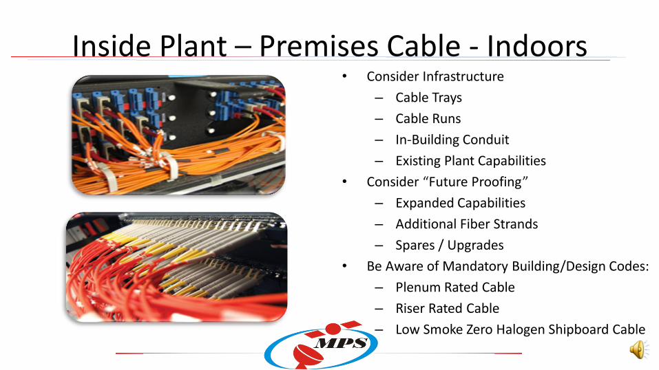
Inside Plant – Premises Cable - Indoors • Consider Infrastructure
– Cable Trays
– Cable Runs
– In-Building Conduit
– Existing Plant Capabilities
• Consider Future Proofing
– Expanded Capabilities
– Additional Fiber Strands
– Spares / Upgrades
• Be Aware of Mandatory Building/Design Codes:
– Plenum Rated Cable
– Riser Rated Cable
– Low Smoke Zero Halogen Shipboard Cable

Outdoor Cable - Aerial Cabling
• Cable Selection Considerations
– Lashed vs. Self Supporting
– Armored vs. Unarmored
– High Tensile Strength
– Breakout Cable Strength
– Splicing (Ribbon vs. Discrete)
– Environmental Conditions
– Low Temperatures
– Rodent Protection
– UV Protection
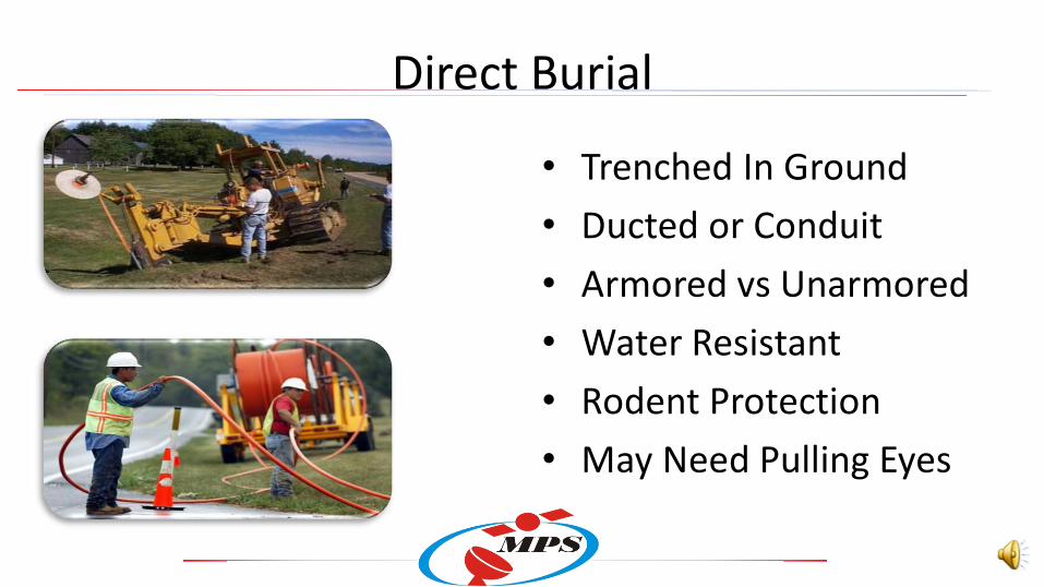
Direct Burial
• Trenched In Ground
• Ducted or Conduit
• Armored vs Unarmored
• Water Resistant
• Rodent Protection
• May Need Pulling Eyes

Structured Cable Plant • Total Solution
• Interconnection Plan
• Support Hardware
• Riser Diagrams
• Teleco / IDF Drawings

Testing and Certifying the Cable Plant

How to talk fiber? Key Terms! • Transmitter , Receiver, Transceivers: These are all types of devices which are
used to create a fiber optic link.
• Wavelength: Refers to the light frequency 1310, 1550 are typical. Others
exists within the ITU Grid Allocation which defines the wavelengths that can
be used in optical networks. Measured in terms of nanometers (nm)
• Jumper Cable/Patch Cable: Point to point cable for connectivity between
patch panels. When Jumper Cables become very long, we call them trunk
cables . Simplex = 1 Strand, Duplex = 2 Strand. Duplex cable could be
crossover cables if needed.
How to talk fiber? Key Terms! • Insertion Loss (Attenuation): How much signal is lost when the light
transits through the cable and connectors. Measure in terms of dB.
• Return Loss (Back Reflections): How much signal is reflected at the
connector. Good return loss means very little light is reflected in the
opposite direction. Measure in terms of dB.
• Interferometry: Method by which you can measure and evaluate the
quality of the optical connector. Connector quality and polishing process
impacts end-face geometry.

How to talk fiber? Key Terms! • Breakout / Fanout: Term used to define how a multi-strand fiber is broken
out into individual strands. These strands can be called sub-members . Note
that the term Breakout Cable would refer to a multi-fiber cable that has
jacketed sub-members (2-3mm) which is different from Distribution Cable
which is a Multi-fiber cable used for direct point to point connectivity,
typically spliced into a panel. Sub-members are tight buffered fiber
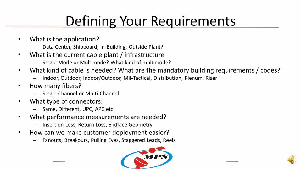
Defining Your Requirements • What is the application?
– Data Center, Shipboard, In-Building, Outside Plant?
• What is the current cable plant / infrastructure – Single Mode or Multimode? What kind of multimode?
• What kind of cable is needed? What are the mandatory building requirements / codes? – Indoor, Outdoor, Indoor/Outdoor, Mil-Tactical, Distribution, Plenum, Riser
• How many fibers? – Single Channel or Multi-Channel
• What type of connectors: – Same, Different, UPC, APC etc.
• What performance measurements are needed? – Insertion Loss, Return Loss, Endface Geometry
• How can we make customer deployment easier? – Fanouts, Breakouts, Pulling Eyes, Staggered Leads, Reels
Additional Learning Resources • Microwave Photonic Systems – 2 or 3 Day Course
• Telcordia Standards Online:
– Generic Requirements for Optical Fiber & Optical Fiber Cable: GR-326-CORE
• The Fiber Optic Association, Inc:
– http://www.thefoa.org
• The International Society for Optics and Photonics
– https://spie.org/
• Fiber Optic Institute
– http://www.fiberoptic.institute/

Key Points / Webinar Summary
• Recognize and Identify the different types of optical connectors
• Differentiate between types of optical cabling and where they are deployed
• Understand the various steps in how an optical connection is made
• Appreciate the importance of connector cleanliness and endface geometry
• Learn how to specify an optical cable and interconnects
• Consider Microwave Photonic Systems / MPS Fiber Optics for your future
requirements.

Questions & Answers