
MAK 206 STRENGTH OF MATERIALS - etu.edu.tracar.etu.edu.tr/mak206/ClassNotes.pdf · 2021. 1. 18. ·...
142
MAK 206 ─ STRENGTH OF MATERIALS (adopted from Hibbeler’s book) CHAPTER 1. STRESS 1.1-1.2. Recall Statics 1.3. Stress 1.4. Average Normal Stress in an Axially Loaded Bar 1.5. Average Shear Stress 1.6. Allowable Stress 1.7. Design of simple connections CHAPTER 2. STRAIN 2.1. Normal Strain and Shear Strain 2.2. Cartesian Strain Components CHAPTER 3. MECHANICAL PROPERTIES OF MATERIALS (reading assignment) CHAPTER 4. AXIAL LOAD 4.1. Saint-Venant’s Principle 4.2. Elastic Deformation of an Axially Loaded Member 4.4. Statically Indeterminate Axially Loaded Member 4.3. Principle of Superposition 4.5. The Force Method of Analysis 4.6. Thermal Stress CHAPTER 5. TORSION 5.1. Torsional Deformation of a Circular Shaft 5.2. The Torsion Formula 5.3. Power Transmission 5.4. Angle of Twist 5.5. Statically Indeterminate Torque-Loaded Members CHAPTER 6. BENDING 6.1-6.2. Construction of shear and bending diagrams for beams 6.3. Bending Deformation of a Straight Member 6.4. The Flexure Formula 6.5. Unsymmetric Bending CHAPTER 7. TRANSVERSE SHEAR 7.1. Shear in Straight Members 7.2. The Shear Formula 7.3. Shear Stress Distribution in Beams Rectangular Cross Section Wide-Flange Beam CHAPTER 8. COMBINED LOADING 8.1. Thin-Walled Pressure Vessels 8.2. State of Stress Caused by Combined Loadings CHAPTER 9. STRESS TRANSFORMATION 9.1. Plane-Stress Transformation 9.2. Plane-Stress Transformation Equations 9.3. Principal Stresses and Maximum Shear Stress 9.4. Mohr Circle (for state of Plane-Stress) 9.5. Absolute Maximum Shear Stress CHAPTER 12. DEFLECTION OF BEAMS AND SHAFTS 12.1. Elastic Curve 12.2. Slope and Displacement Calculation by Integration 12.5. Method of Superposition 12.6. Statically Indeterminate Beams and Shafts
Transcript of MAK 206 STRENGTH OF MATERIALS - etu.edu.tracar.etu.edu.tr/mak206/ClassNotes.pdf · 2021. 1. 18. ·...

MAK 206 ─ STRENGTH OF MATERIALS (adopted from Hibbeler’s book)
CHAPTER 1. STRESS 1.1-1.2. Recall Statics 1.3. Stress 1.4. Average Normal Stress in an Axially Loaded Bar 1.5. Average Shear Stress 1.6. Allowable Stress 1.7. Design of simple connections CHAPTER 2. STRAIN 2.1. Normal Strain and Shear Strain 2.2. Cartesian Strain Components CHAPTER 3. MECHANICAL PROPERTIES OF MATERIALS (reading assignment) CHAPTER 4. AXIAL LOAD 4.1. Saint-Venant’s Principle 4.2. Elastic Deformation of an Axially Loaded Member 4.4. Statically Indeterminate Axially Loaded Member 4.3. Principle of Superposition 4.5. The Force Method of Analysis 4.6. Thermal Stress CHAPTER 5. TORSION 5.1. Torsional Deformation of a Circular Shaft 5.2. The Torsion Formula 5.3. Power Transmission 5.4. Angle of Twist 5.5. Statically Indeterminate Torque-Loaded Members CHAPTER 6. BENDING 6.1-6.2. Construction of shear and bending diagrams for beams 6.3. Bending Deformation of a Straight Member 6.4. The Flexure Formula 6.5. Unsymmetric Bending
CHAPTER 7. TRANSVERSE SHEAR 7.1. Shear in Straight Members 7.2. The Shear Formula 7.3. Shear Stress Distribution in Beams
Rectangular Cross Section
Wide-Flange Beam CHAPTER 8. COMBINED LOADING 8.1. Thin-Walled Pressure Vessels 8.2. State of Stress Caused by Combined Loadings CHAPTER 9. STRESS TRANSFORMATION 9.1. Plane-Stress Transformation 9.2. Plane-Stress Transformation Equations 9.3. Principal Stresses and Maximum Shear Stress 9.4. Mohr Circle (for state of Plane-Stress) 9.5. Absolute Maximum Shear Stress CHAPTER 12. DEFLECTION OF BEAMS AND SHAFTS 12.1. Elastic Curve 12.2. Slope and Displacement Calculation by Integration 12.5. Method of Superposition 12.6. Statically Indeterminate Beams and Shafts

CHAPTER 1 NOTES 1 / 21
CHAPTER 1. STRESS
OUTLINE
1.1-1.2. Recall Statics
1.3. Stress
1.4. Average Normal Stress in an Axially Loaded Bar
1.5. Average Shear Stress
1.6. Allowable Stress
1.7. Design of simple connections

CHAPTER 1 NOTES 2 / 21
1.1-1.2. Recall Statics
A body can be subjected to several different types of
external loads. They can be classified as either
surface forces (concentrated or distributed)
body forces
In addition to the external loads, the support reactions
should also be shown in free body diagrams (FBD).
-- If the support prevents translation, a reaction force is
developed on the body
-- If the support prevents rotation, a reaction moment is
developed on the body
Equations of equilibrium (Denge denklemleri)
Use equations of equilibrium to compute
unknown support reactions
Internal resultant loadings (N,V,M,T)

CHAPTER 1 NOTES 3 / 21
Internal resultant loadings (İç bileşke kuvvetler)
Coplanar Loading (Düzlemsel yükleme)

CHAPTER 1 NOTES 4 / 21
Example 1: Determine the resultant internal loadings acting on the cross section at C of the beam.

CHAPTER 1 NOTES 5 / 21
Example 2: Determine the resultant internal loadings acting on the cross section at B of the pipe. The pipe has a mass of 2 kg/m
and is subjected to both a vertical force of 50 N and a moment of 70 N·m at its end A. It is fixed to the wall at C.

CHAPTER 1 NOTES 6 / 21
1.3. Stress
Normal stress:
denoted with σ.
described with one index only.
Shear stress:
denoted with τ.
described with two indices.
the first index defines the orientation of the area that the stress acts
the second index defines the axis along which the stress acts
MAK 104 STATICS
MAK 206 MECHANICS OF MATERIALS
CHAPTER 1 NOTES 7 / 21
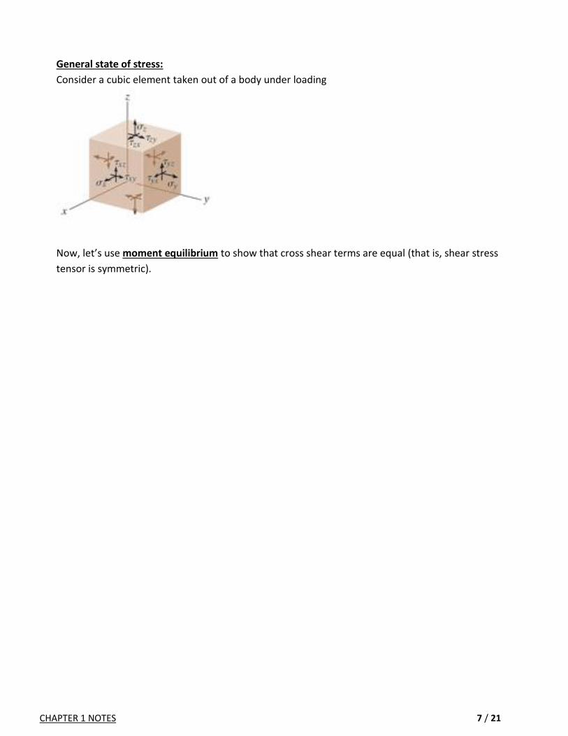
General state of stress:
Consider a cubic element taken out of a body under loading
Now, let’s use moment equilibrium to show that cross shear terms are equal (that is, shear stress
tensor is symmetric).

CHAPTER 1 NOTES 8 / 21
1.4. Average Normal Stress in an Axially Loaded Bar - truss members
- we can neglect their weight (small compared to loading)
Assumptions
1. The bar remains straight before and after the load is
applied, and the cross-section remains plane after
deformation → uniform deformation
2. The load should be applied along the centroidal axis
3. The material should be homogenous and isotropic
Equations of equilibrium
Rz zF F
where σ is the average normal stress, N is the internal resultant
normal force, and A is the cross-sectional area.
Rx xM M
Ry yM M
Equations (1) and (2) are automatically satisfied, because N pass
through the centroid, for which 0x dA and 0y dA .
Maximum average normal stress
N
A
Thus, it is important to find the maximum of (N/A). It may be helpful to draw a normal force diagram.
may change along the length of the bar due to various external loads
section area may change along the length of the bar

CHAPTER 1 NOTES 9 / 21
Example: The thrust bearing is subjected to the loads shown. Determine the average normal stress developed on cross sections
through points B, C, and D.

CHAPTER 1 NOTES 10 / 21
1.5. Average Shear Stress (Ortalama Kayma Gerilmesi)
avgaverage shear stress
V = shear force (internal load)
A = shear area
bolted (or riveted) glued
thin plates
As the plates are thin, the bending moment due to F can be neglected.
For thick plates, F will have a bending effect in addition to shearing.

CHAPTER 1 NOTES 11 / 21
Example: The bar is held in equilibrium by the pin supports at A and B. Note that the support at A has a single leaf and therefore it
involves single shear in the pin, and the support at B has a double leaf and therefore it involves double shear.
The allowable shear stress for both pins is τallow = 125 MPa. If x = 1 m and w= 12 kN/m, determine the smallest required
diameter of pins A and B. Neglect any axial force in the bar.

CHAPTER 1 NOTES 12 / 21
1.6. Allowable Stress
The stress in machine element must remain below certain values.
These values are selected to be smaller than the true limits of the material.
Many unknown factors influence the actual stress in a member.
A factor of safety (F.S.) is needed to obtained allowable load.
F.S. is a ratio of the failure load divided by the allowable load
Usually, the load and stress are linearly related, so we have

CHAPTER 1 NOTES 13 / 21
1.7. Design of simple connections
A) Tension member
B) Connector (bolt, pin)
C) Bearing member D) Shear due to axial loading

CHAPTER 1 NOTES 14 / 21
Example 1: The specimen failed in a tension test at an angle of 52° when the axial load was 100 kN. If the diameter of the
specimen is 12 mm, determine the average normal and average shear stress acting on the area of the inclined failure
plane. Also, what is the average normal stress acting on the cross section when failure occurs?

CHAPTER 1 NOTES 15 / 21
Example 2:

CHAPTER 1 NOTES 16 / 21
Example 3: The 250-N lamp is supported by three steel rods connected by a ring at A. The diameter of each rod is given in the
figure.
Determine the angle of orientation θ of AC such that the average normal stress in rod AC is twice the average normal
stress in rod AD. What is the magnitude of stress in each rod?

CHAPTER 1 NOTES 17 / 21
Example 4: The row of staples AB contained in the stapler is glued together so that
the maximum shear stress the glue can withstand is τmax = 84 kPa.
Determine the minimum force F that must be placed on the plunger in
order to shear off a staple from its row and allow it to exit undeformed
through the Groove at C.
The outer dimensions of the staple are shown in the figure. It has a
thickness of 1.25 mm Assume all the other parts are rigid and neglect friction.

CHAPTER 1 NOTES 18 / 21
Example 5: The beam is supported by a pin at A and a short link BC.
Determine the maximum magnitude P of the loads the beam will
support if the average shear stress in each pin is not to exceed 80
MPa. All pins have the same diameter of 18 mm.

CHAPTER 1 NOTES 19 / 21
Example 6: The shaft is subjected to the axial force of 30 kN. If the shaft passes through the 53-mm diameter hole in the fixed
support A, determine the bearing stress acting on the collar C. Also, what is the average shear stress acting along the
inside surface of the collar where it is fixed connected to the 52-mm diameter shaft?

CHAPTER 1 NOTES 20 / 21
Example 7: The joint is fastened together using two bolts. Determine the required diameter of the bolts if the failure shear stress for the
bolts is τfail = 350 MPa. Use a factor of safety for shear of F.S. = 2.5.

CHAPTER 1 NOTES 21 / 21
Example 8:
The pins at A, B and D are made of steel, for which the
shear failure stress is given as 100 MPa.
Use a factor of safety of 2.5 to design the pin
diameters.

CHAPTER 2 NOTES 1 / 8
CHAPTER 2. STRAIN
OUTLINE
2.1. Normal Strain and Shear Strain
2.2. Cartesian Strain Components

CHAPTER 2 NOTES 2 / 8
2.1. Normal Strain and Shear Strain
Deformation
When a force is applied to a body, it will change the body’s shape and size.
These changes are called deformation.
Normal strain
The elongation / contraction of a line segment per unit of length is referred to as normal strain.
Average normal strain is defined as
If the normal strain is known, then the approximate final length is
Shear strain
Change in angle between two line segments that were perpendicular to one another refers to
shear strain.
Note the before and after positions of
3 line segments where the material is
subjected to tension.

CHAPTER 2 NOTES 3 / 8
2.2. Cartesian Strain Components
Assume that a deformed body is subdivided into small
rectangular elements, and we concentrate on such an
element
Normal strain components volume change
(lengths of the sides of the rectangular element changes)
∆x
∆y
∆z
Shear strain components shape change
(angles of the sides of the rectangular element changes)
2
2
2
Small strain analysis:
Most engineering materials undergo small deformations, so small strains develop. ε << 1
This allows us to use the following approximate values: sin ε ≈ ε, cos ε ≈ 1, tan ε ≈ ε .

CHAPTER 2 NOTES 4 / 8
Example 1:
The beam is hanging under its own weight such that 310y y
a) Determine displacement of end A b) Compute the average normal strain
CHAPTER 2 NOTES 5 / 8
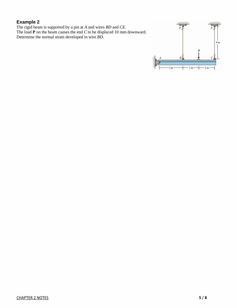
Example 2 The rigid beam is supported by a pin at A and wires BD and CE.
The load P on the beam causes the end C to be displaced 10 mm downward.
Determine the normal strain developed in wire BD.

CHAPTER 2 NOTES 6 / 8
Example 3 Nylon strips are fused to glass plates. When moderately heated, the nylon will become soft while the glass stays approximately rigid. Determine the average shear strain in each layer of nylon due to the load P when the assembly deforms as shown.

CHAPTER 2 NOTES 7 / 8
Example 4 The square deforms into the position shown by the dashed lines.
Determine the shear strain at each of its corners, A, B, C, and D.
(Side D'B' remains horizontal.)

CHAPTER 2 NOTES 8 / 8
Example 5 The plate distorts into the dashed position shown. Determine
(a) the average normal strains and the shear strain at A, (b) the average normal strain along line BE.

CHAPTER 3 NOTES 1 / 8
CHAPTER 3. MECHANICAL PROPERTIES OF MATERIALS
OUTLINE 3.1. The Tension and Compression Test
3.2. The Stress-Strain Diagram
3.3. Stress-Strain Behavior of Ductile and Brittle Materials
3.4. Hooke’s Law
3.5. Strain Energy
3.6. Poisson’s Ratio
3.7. The Shear Stress-Strain Diagram
3.8. Creep and Fatigue

CHAPTER 3 NOTES 2 / 8
CHAPTER 3: MECHANICAL PROPOERTIES OF MATERIALS
3.1. THE TENSION / COMPRESSION TEST
Used primarily to determine the relationship between the
average normal stress and the average normal strain
Metals
Ceramics
Polymers
Composite materials
When a metal specimen is tested, generally its initial diameter is d0=13 mm. Two punch marks with
L0 = 50 mm distance is used. The specimen is stretched at a very slow, constant rate until it reaches
the breaking point. During the test, the applied load P and the elongations δ= L- L0 are recorded at
frequent intervals.
3.2. THE STRESS-STRAIN DIAGRAM
Engineering stress 0
P
A True stress
P
A
Engineering strain 0L
True strain
0
lnL
L
Proportional limit …: lineer gerilme gerinim davranışı (doğrusallık sınırı)
Elastic limit …………..: yük kaldırıldığında orjinal şekline geri döner
Yielding …….…….…….: kalıcı deformasyon
Strain hardening ……: gerinim sertleşmesi
Necking …………………: boyun yapma
Failure …………………..: kopma

CHAPTER 3 NOTES 3 / 8
3.3. STRESS-STRAIN BEHAVIOR OF DUCTILE AND BRITTLE MATERIALS
Ductile materials (Sünek malzemeler)
Large strain before rupture
Capability of absorbing shock and energy
Steel, aluminum, brass, zinc
Measures of ductility
Percent elongation = 0
0
fL L
L
(100%) (Percent elongation in Fig. 3.6 is 38%)
Percent reduction of area = 0
0
fA A
A
(100%)
Engineering stress-strain diagram for low carbon steel and aluminum
Elastic behavior → yielding at constant stress → strain
hardening → necking → failure
There is no well-defined yield point!
Offset method is used to find the
yield strength * For aluminum proportional limit, elastic limit, and yield point are all the same (unless otherwise specified).

CHAPTER 3 NOTES 4 / 8
Brittle materials (Gevrek malzemeler)
Little or no yielding before failure
Much larger resistance to compression than tension
Gary cast iron, concrete
Engineering stress-strain diagram for gray cast iron and concrete
Both ductile and brittle behavior
Most materials exhibit both ductile and brittle behavior
Steel has brittle behavior when it contains high carbon
content, and it is ductile when the carbon content is
reduced.
Materials become more brittle at low temperatures,
whereas they become more ductile at high
temperatures

CHAPTER 3 NOTES 5 / 8
3.4. HOOKE'S LAW
Linear relationship between stress and strain E (similar
to F= k x)
E -- modulus of elasticity (a stiffness property)
For steel, E=200 GPa
For aluminum, E=70 GPa
For rubber, E=0.7 MPa
To use E , the linear-elastic behavior must be
maintained. If the stress in the material exceeds
the proportional limit, E is no longer valid!
Strain energy
If a ductile material is loaded into the plastic region and then unloaded, elastic strain is recovered
whereas the plastic strain remains (Fig.3-14a). As a result, the material is subjected to a permanent set.
If the material is loaded again, the yielding occurs at a higher yield point A’ (Fig.3-14a). As a consequence,
the material hardens.
If the loading/unloaded is applied in a cyclic manner, some heat or energy will be lost and mechanic
hysteresis occurs (the colored area in Fig. 3-14b).

CHAPTER 3 NOTES 6 / 8
3.5. STRAIN ENERGY
As a material is deformed by external loading, it store energy internally throughout its volume.
Energy = Work = Force × Displacement
∆U = ∆F/2 (ε ∆z) = ½ σ ∆x ∆y (ε ∆z) = ½ σ ε (∆x ∆y ∆z)
1
2U V
Strain Energy Density 21 1
2 2
Uu
V E
Modulus of Resilience
The area under σ-ε diagram within
the proportional limit
Modulus of Toughness
The entire area under σ-ε
diagram
3.6. POISSON'S RATIO
When a deformable body is subjected to an axial tensile force, it elongates but contracts laterally.
Longitudinal and lateral strains
longL
lateral
R
Poisson's ratio
lateral
long
In principle, 0 ≤ ν ≤ 0.5
For most engineering materials, it ranges between
1/4 and 1/3

CHAPTER 3 NOTES 7 / 8
3.7. THE SHEAR STRESS-STRAIN DIAGRAM
G
pl
pl
G
2 1
EG
3.8. FAILURE DUE TO CREEP (SÜRÜNME) AND FATIGUE (YORULMA)
Creep
When a material has to support a load for a very long period of time, the material may continue to
deform until a sudden fracture occurs. This time-dependent permanent deformation is known as
creep.
Temperature is also an important factor
o Metals and ceramics creep at high temperature
o Composite materials creep even at room temperature
Effect of stress Effect of temperature

CHAPTER 3 NOTES 8 / 8
Fatigue
Repeated loading causes materials to fail below yield stress
Ductile materials exhibit brittle behavior at failure
Connecting rods, crankshafts, gas turbines
Repeated stress S-N curve

CHAPTER 4 NOTES 1 / 19
CHAPTER 4. AXIAL LOAD
OUTLINE 4.1. Saint-Venant’s Principle
4.2. Elastic Deformation of an Axially Loaded Member
4.4. Statically Indeterminate Axially Loaded Member
4.3. Principle of Superposition
4.5. The Force Method of Analysis
4.6. Thermal Stress
(Section 4.4 intentionally precedes 4.3)

CHAPTER 4 NOTES 2 / 19
CHAPTER 4: AXIAL LOADING
Chapter 1 → * normal stress at axially loaded member: NA
Chapter 4 → * deformation in this member
* support reactions that cannot be found via equil. eqs.
* thermal stresses
4.1. Saint-Venant's Principle
At a considerable distance away from the localized effects, stress distribution is the
same for all statically equivalent loadings ( ,R RF M
should be same).
How far away?
As a general rule, the largest dimension of the loaded section
For thin-walled members and loadings with large deformations, the largest dimension is not far enough! 4.2. Elastic deformation of an axially loaded member

CHAPTER 4 NOTES 3 / 19
Example 1 Compute the axial deformation of the steel rod (E = 200 GPa) shown below.

CHAPTER 4 NOTES 4 / 19
4.4. Statically Indeterminate Axially Loaded Member (Section 4.4 intentionally precedes 4.3) A member is statically indeterminate when equations of equilibrium are not sufficient to determine the reactions on a member. Additional equations are needed. We consider the deformed geometry and write additional equations that ensures a compatible deformation in a deformed body. These equations are called compatibility conditions.
Equilibrium equation: Notice that this equation is not sufficient to determine the two reactions on the bar.
Let’s write the compatibility condition that the length of the bar should
remain unchanged since we have fixed support at both ends. Now, we can combine equilibrium equation with compatibility condition

CHAPTER 4 NOTES 5 / 19
Example 1. The assembly consists of three titanium rods (E=120GPa) rods and a rigid
bar AC.
Determine the horizontal displacement of point F.

CHAPTER 4 NOTES 6 / 19
Example 2. The three A-36 steel wires each have a diameter of 2 mm and unloaded lengths of LAC = 1.60 m and LAB = LAD =
2.00 m. Determine the force in each wire after the 150-kg mass is suspended from the ring at A.

CHAPTER 4 NOTES 7 / 19
4.3. Principle of Superposition Principle of superposition is used to simplify stress and displacement problems by subdividing the
loading into components and adding the results.
The following two conditions need to be satisfied to be able to use it

CHAPTER 4 NOTES 8 / 19
4.5. The Force Method of Analysis This method is used to solve statistically indeterminate problems.
Compatibility equation is written by using principle of superposition.
Consider our running example

CHAPTER 4 NOTES 9 / 19
Example 1. The column is constructed from high-strength concrete and six A-36 steel reinforcing rods. If it is subjected to an axial
force of 150 kN, determine the required diameter of each rod so that one-fourth of the load is carried by the concrete and
three-fourths by the steel.

CHAPTER 4 NOTES 10 / 19
Example 2. If the gap between C and the rigid wall at D is initially 0.15 mm, determine the support reactions at A and D when the
force is applied. The assembly is made of A36 steel (E=200GPa).

CHAPTER 4 NOTES 11 / 19
Example 3. Three steel rods (E 200 GPa) support a 36-kN load P.
Each of the rods AB and CD has a 200-mm2 cross-sectional area
and rod EF has a 625 mm2 cross-sectional area.
Determine (a)the change in length of rod EF, (b) the stress in each rod.

CHAPTER 4 NOTES 12 / 19
Example 4. The rigid bar is supported by the two short wooden posts (Ew = 11 GPa) and a
spring (k=1.8 MN/m, original length of 520mm).
Each of the posts has length of 500mm and sectional area of 800mm2.
Determine the vertical displacement of A and B.

CHAPTER 4 NOTES 13 / 19
Example 5. The 10-mm-diameter steel bolt is surrounded by a bronze sleeve. The outer diameter of this sleeve is 20 mm, and its inner
diameter is 10 mm. If the yield stress for the steel is (σY)st = 640 MPa, and for the bronze (σY)br = 520 MPa, determine the
magnitude of the largest elastic load P that can be applied to the assembly. Est = 200 GPa, Ebr = 100 GPa.

CHAPTER 4 NOTES 14 / 19
4.6. Thermal Stress A change in temperature cause a mayoral to change its dimensions
The experiments have shown that the expansion (or contraction) is linearly related to the
temperature change
If the temperature varies throughout the length of the member

CHAPTER 4 NOTES 15 / 19
Example 1. The device is used to measure a change in temperature. Bar AB is made of steel (α=12×10-6 1/oC), and bar CD is made of
aluminum (α=23×10-6 1/oC). When the temperature is at 25 oC, the rigid bar ACE is in horizontal position.
Determine the vertical displacement of end E when the temperature rises to 75 oC.

CHAPTER 4 NOTES 16 / 19
Example 2.
For brass, take α=18×10-6 1/oC, E=100 GPa
For aluminum, take α=23×10-6 1/oC, E=70 GPa

CHAPTER 4 NOTES 17 / 19
Example 3. The AM1004-T61 magnesium alloy tube AB is capped with a rigid plate E.The gap between
E and end C of the 6061-T6 aluminum alloy solid circular rod CD is 0.2 mm when the
temperature is at 30° C. Determine the normal stress developed in the tube and the rod if the
temperature rises to 80° C. Neglect the thickness of the rigid cap.
For Mg, take α=26×10-6 1/oC, E=44.7 GPa
For Al, take α=24×10-6 1/oC, E=68.9 GPa

CHAPTER 4 NOTES 18 / 19
Example 5. The assembly has the diameters and material make-up indicated. If it fits securely between its fixed supports when the
temperature is T1 = 20°C, determine the average normal stress in each material when the temperature reaches T2 = 40°C.
For Al, take α=23×10-6 1/oC, E=73 GPa
For Br, take α=17×10-6 1/oC, E=103 GPa
For SS, take α=17×10-6 1/oC, E=193 GPa

CHAPTER 4 NOTES 19 / 19
Example 6. The center rod CD of the assembly is heated from T1 = 30°C to T2 = 180°C using electrical resistance heating. At the lower
temperature T1 the gap between C and the rigid bar is 0.7 mm. Determine the force in rods AB and EF caused by the
increase in temperature. Rods AB and EF are made of steel, and each has a cross-sectional area of 125 mm2. CD is made
of aluminum and has a cross-sectional area of and 375 mm2.
Est = 200 GPa, Eal = 70 GPa, αst = 12(10-6)/°C, αal = 23(10-6)/°C.

CHAPTER 5 NOTES 1 / 19
CHAPTER 5. TORSION
OUTLINE 5.1. Torsional Deformation of a Circular Shaft
5.2. The Torsion Formula
5.3. Power Transmission
5.4. Angle of Twist
5.5. Statically Indeterminate Torque-Loaded Members

CHAPTER 5 NOTES 2 / 19
5.1. Torsional Deformation of a Circular Shaft
During deformation
Circles remain circles
Cross sections at the ends
of the shaft remain flat
(no warping, no bulging)
Uniform deformation
If angle of twist is small,
length and diameter of
the shaft do not change.
Shear strain linearly changes with
the radial distance (ρ) from the shaft maxc

CHAPTER 5 NOTES 3 / 19
5.2. The Torsion Formula
Recall from Section 5.1 that maxc
For linear-elastic materials G
So we have, maxc
Consider the torque produced on the shaft
Polar moment of inertia, J
2 2
0
2
c
A
J dA d
…
Torque on the shaft produces a linear shear stress distribution in each radial line of the cross section. Similarly, an
associated shear stress is developed on an axial plane. This associated shear stress may split the wooden shafts.

CHAPTER 5 NOTES 4 / 19
Example 1 The shaft shown is supported by two bearings and is subjected to three torques. Determine the shear stress
developed at A and B, located at section a-a of the shaft.

CHAPTER 5 NOTES 5 / 19
Example 2.
Determine the maximum torsional stress developed at C.

CHAPTER 5 NOTES 6 / 19
Example 3.

CHAPTER 5 NOTES 7 / 19
Example 4.

CHAPTER 5 NOTES 8 / 19
Example 5. The steel shaft is subjected to the torsional loading shown.
Determine the absolute maximum shear stress in the shaft
and sketch the shear-stress distribution along a radial line
where it is maximum.

CHAPTER 5 NOTES 9 / 19
Example 6. The shaft consists of three concentric tubes, each made
from the same material and having the inner and outer
radii shown. If a torque of T = 800 N·m is applied to
the rigid disk fixed to its end, determine the maximum
shear stress in the shaft.

CHAPTER 5 NOTES 10 / 19
5.3. Power Transmission (Güç Aktarımı)
Shafts and tubes having circular cross sections are often used to transmit power.
Work d
Power Wunit time dt
Work = Torque × Angle of rotation ( W = T × θ )
So we have, P = d
T Tdt
(Watt) ω: angular velocity (rad/s)
For machinery applications, the frequency of rotation of the shaft is often reported.
f = number of cycles per second (Hz)
Angular velocity and frequency are related through ω = 2π f
Thus, the transmitted power can be related to the applied torque via P = 2 π f Ta
Shaft design
2
PT
f and max allow
Tc
J are used to design shafts under stress considerations
For tubular shafts, the polar moment of inertia is computed from 4 4
2o iJ c c
, where co is the outer
radius and ci is the inner radius.

CHAPTER 5 NOTES 11 / 19
Example 1.

CHAPTER 5 NOTES 12 / 19
Example 2. The solid steel shaft AC has a diameter of 25 mm and is supported by smooth bearings at D and E. It is
coupled to a motor at C, which delivers 3 kW of power to the shaft while it is turning at 50 rev/s. If gears A
and B remove 1 kW and 2 kW, respectively, determine the maximum shear stress developed in the shaft
within regions AB and BC. The shaft is free to turn in its support bearings D and E.

CHAPTER 5 NOTES 13 / 19
5.4. Angle of Twist (Dönme Açısı), φ
In shaft design, the angle of twist of shafts are occasionally restricted.
In addition, angle of twist is important when analyzing the support reactions of statically
indeterminate shafts.
Constant torque and cross section Varying torque or cross section
Sign convention

CHAPTER 5 NOTES 14 / 19
5.5. Statically Indeterminate Torque-Loaded Members
If the moment equilibrium equations is inadequate to
determine the unknown reactive torques, then additional
equation(s) will be required.
Compatibility equations (in terms of angle of twist) are used to
obtain additional equations.

CHAPTER 5 NOTES 15 / 19
Example 1. A composite shaft is subjected to T=T’=400 N.m.
Determine the safety factors for the brass jacket and steel core.
(τfail)brass = 20 MPa, (τfail)steel = 45 MPa.
Gbrass = 39 MPa, Gsteel = 77.2 MPa.

CHAPTER 5 NOTES 16 / 19
Example 2. The two shafts are made of A-36 steel (G=75 GPa). Each has a diameter of 25 mm, and they are supported
by bearings at A, B, and C, which allow free rotation. If the support at D is fixed, determine the angle of
twist of end B when the torques are applied to the assembly as shown.

CHAPTER 5 NOTES 17 / 19
Example 3. The 30-mm-diameter shafts are made of steel (G=75GPa). They are supported on journal bearings that
allow the shaft to rotate freely. If the motor at A develops a torque of on the shaft AB, while the turbine at
E is fixed from turning, determine the amount of rotation of gears B and C.

CHAPTER 5 NOTES 18 / 19
Example 4. The two 1-m-long shafts are made of aluminum (G=27GPa).
Each has a diameter of 30 mm and they are connected using the
gears fixed to their ends. Their other ends are attached to fixed
supports at A and B. They are also supported by bearings at C
and D, which allow free rotation of the shafts along their axes.
If a torque of 900 N·m is applied to the top gear as shown,
determine the maximum shear stress in each shaft.

CHAPTER 5 NOTES 19 / 19
Example 5. The two shafts AB and EF are fixed at their ends and fixed connected to s that are in mesh with a common
gear at C, which is fixed connected to shaft CD If a torque of T = 80 N·m is applied to end D, determine
the angle of twist of end D ach shaft as a diameter of 20 mm and is made from A-36 steel. G = 75 GPa

CHAPTER 6 NOTES 1 / 19
CHAPTER 6. BENDING
OUTLINE
6.1-6.2. Construction of shear and bending diagrams for beams
6.3. Bending deformation of a Straight Member
6.4. The Flexure Formula
6.5. Unsymmetric Bending

CHAPTER 6 NOTES 2 / 19
CHAPTER 6. BENDING (EĞİLME)
6.1-6.2: Construction of shear and bending diagrams for beams Beams: Members that are slender and support loads that are applied perpendicular to their longitudinal axis
Beams might be subjected to point and/or distributed loads.
Beam design requires calculation of the shear and moment
variation over the length of the beam.
V(x) and M(x) diagrams
Sign convention
The graphical method to draw V(x) and M(x) diagrams
Applying equilibrium equations (∑Fy=0 and ∑Mo=0) to Fig. 6-10b we get
dV
w xdx
, dM
Vdx
V w x dx , M V x dx

CHAPTER 6 NOTES 3 / 19
Table 6-1: Application of the graphical method to some common loading cases

CHAPTER 6 NOTES 4 / 19
Examples
Draw the shear and moment diagrams of the followings by using the graphical method

CHAPTER 6 NOTES 5 / 19
Draw the shear and moment diagrams of the followings by using the graphical method

CHAPTER 6 NOTES 6 / 19
6.3. Bending deformation of a Straight Member
Beams made of homogenous materials (composite materials: Section 6.6, we do not cover)
Cross sectional area is symmetric with respect to an axis and bending moment is applied about an axis perpendicular to this axis of symmetry
(unsymmetric bending: Section 6.5, we will cover)
When bending moment is applied,
Horizontal lines become curved
Vertical lines remain straight, but
they rotate
Three assumptions
1. No change in length on longitudinal axis within the neutral surface
2. All cross sections remain plane
3. No deformation of cross section within its own plane

CHAPTER 6 NOTES 7 / 19
6.4. The Flexure Formula

CHAPTER 6 NOTES 8 / 19
Example 1.
Compute the factor of safety for the aluminum beam shown.
Take σY=414 MPa.

CHAPTER 6 NOTES 9 / 19
Example 2.
Determine the absolute maximum bending stress in the beam when w=7.5 kN/m.

CHAPTER 6 NOTES 10 / 19
Example 3.
The beam shown has a square cross section of b mm
on each side. If the allowable bending stress is 400
MPa, determine the smallest value of b.
CHAPTER 6 NOTES 11 / 19
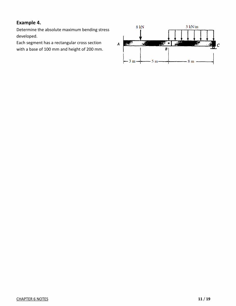
Example 4.
Determine the absolute maximum bending stress
developed.
Each segment has a rectangular cross section
with a base of 100 mm and height of 200 mm.

CHAPTER 6 NOTES 12 / 19
6.5. Unsymmetric Bending
While developing M y
I
(flexure formula), we imposed the
following conditions
The cross sectional area should
be symmetric about an axis perpendicular to the neutral axis
The resultant internal moment M should act along the neutral axis
In this section, we will show how the flexure formula can also be applied to
a beam having a cross sectional area of any shape
a beam having a resultant internal moment that acts in any direction
A) Beam having a cross sectional area of any shape
Equilibrium equations
Positioning the principal axes
If the cross section is symmetric, y and z axes are naturally principal axes.
If the cross section is unsymmetric, the principal axes can be positioned using Mohr's circle or transformation
equations (see Appendix A of Hibbeler's book).

CHAPTER 6 NOTES 13 / 19
Example.
Find the orientation of the principal axes for the cross section shown.

CHAPTER 6 NOTES 14 / 19
B) Resultant internal moment acts in any direction
After resolving the moment into its components, we have yz
z y
M zM y
I I
(DO NOT MEMORIZE THE PLUS AND MINUS SIGNS!! TRY TO UNDERSTAND)
Orientation of the Neutral Axis
Normal stress is zero on the neutral axis → 0yz
z y
M zM y
I I
coszM M and sinyM M → tan tanz
y
I
I where tan y z
Note: The angles θ and α are measured positive from +z axis toward +y axis.
My = 12.99 kN.m
Mz = 7.50 kN.m
Iz = 20.53×10⁻⁶ m4
Iy = 13.92×10⁻⁶ m4
tan θ = 12.99/7.50 → θ = 60˚
20.53tan tan 60
13.92 → α = 68.6˚

CHAPTER 6 NOTES 15 / 19
Example 1. Determine the maximum magnitude of the bending moment M so that the bending stress in the member
does not exceed 100 MPa.

CHAPTER 6 NOTES 16 / 19
Example 2. Determine the stresses at points A, B, C and D.

CHAPTER 6 NOTES 17 / 19
Example 3. The resultant moment acting on the cross section of the aluminum strut has magnitude of = 800 N-m and is directed as shown. Determine the maximum bending stress in the strut. Note: The location of the centroid C of the struts cross-sectional area must be determined first.

CHAPTER 6 NOTES 18 / 19
Example 4. The 30-mm-diameter shaft is subjected to the vertical and horizontal loadings of two pulleys as shown It is supported on two journal bearings at A and B which offer no resistance to axial loading. Furthermore, the coupling to the motor at C can be assumed not to offer any support to the shaft. Determine the maximum bending stress developed in the shaft.

CHAPTER 6 NOTES 19 / 19
Extra page for Example 4

CHAPTER 7 NOTES 1 / 10
CHAPTER 7. TRANSVERSE SHEAR
OUTLINE
7.1. Shear in Straight Members
7.2. The Shear Formula
7.3. Shear Stress Distribution in Beams
Rectangular Cross Section
Wide-Flange Beam

CHAPTER 7 NOTES 2 / 10
CHAPTER 7: TRANSVERSE SHEAR (ENİNE KAYMA)
7.1. Shear in Straight Members
Beams generally support both shear and moment loadings
Due to the complementary property of shear, transverse shear stress is also associated to longitudinal shear stress.
Why shear stress develops on the longitudinal planes of the beam ?
Consider the beam made from three boards that are not bonded together (Fig. 7-2). The application of a the force P will cause the boards to slide over each other.
If the boards are bonded, then the longitudinal shear stress will prevent sliding of the boards.
As a result of the shear stresses, shear strains are developed.
These shear strains are in a complex manner (they are not linearly varying as in bending and torsion).
This non-uniform shear strain variation will cause the cross section to warp (çarpılma).
For axial loading, the strains are constant. Similarly, for bending and torsion, the strains are linear. Thus, we were able to start from strain distributions to compute stresses.
For transverse shear, on the other hand, the strains are nonlinear and cannot be easily expressed mathematically. Therefore, we will not start from strains to compute stresses.
Instead, we will compute shear stresses using the V = dM/dx formula.

CHAPTER 7 NOTES 3 / 10
7.2. The Shear Formula
Consider a beam under external loading.
Concentrate on a section that is y’ distance away from the neutral axis.
Equilibrium Equation

CHAPTER 7 NOTES 4 / 10
7.3. Shear Stress Distribution in Beams
Rectangular Cross Section
221 1
2 2 2 2 4
h h hQ y A y y y b y b
22
3
6
4
VQ V hy
It bh
(parabolic distribution)
The shear stress is MAXIMUM on the neutral plane max 1.5V
A
(Recall that the normal stress is zero on the neutral plane)
Wide-Flange Beam (Geniş Flanşlı Kiriş)
As the thickness changes instantly
A jump occurs in shear stress distribution

CHAPTER 7 NOTES 5 / 10
Example 1: For the cross section shown,
(a) Plot the shear-stress distribution over the cross section
(b) Determine how much of the shear load is carried by the web
(c) Determine how much of the bending moment (if acts) is carried by the flanges

CHAPTER 7 NOTES 6 / 10
Example 1 (continued):

CHAPTER 7 NOTES 7 / 10
Example 2: Plot the shear-stress distribution over the cross section of a rod that has a radius c.

CHAPTER 7 NOTES 8 / 10
Example 3: Calculate the shear stress distribution over the section shown

CHAPTER 7 NOTES 9 / 10
Example 4: The beam is made from three polystyrene strips that are glued together as shown. If the glue has a shear strength of 80
kPa, determine the maximum load P that can be applied without causing the glue to lose its bond.

CHAPTER 7 NOTES 10 / 10
Example 5: Determine the maximum shear stress acting in the beam at the critical section.

CHAPTER 8 NOTES 1 / 9
CHAPTER 8. COMBINED LOADING
OUTLINE
8.1. Thin-Walled Pressure Vessels
8.2. State of Stress Caused by Combined Loadings

CHAPTER 8 NOTES 2 / 9
CHAPTER 8: COMBINED LOADING (BİLEŞİK YÜKLEME)
8.1. Thin-Walled Pressure Vessels
Cylindrical or spherical vessels are commonly used as boilers or tanks
For thin walled vessels, / 10r t .
If / 10r t , then 0.96thin walled actual
The stress distribution throughout the thickness do not change significantly, so it is assumed to be
uniform (or constant)
Cylindrical Vessels - an element of the material will be subjected to a biaxial state of stress
For Fig. 8-1(b), 0,xF
For Fig. 8-1(c), 0,yF
Spherical Vessels
For Fig. 8-2(b), 0,yF

CHAPTER 8 NOTES 3 / 9
Example 1: The tank of the air compressor is subjected to an internal pressure of 0.63 MPa. If the internal diameter of the tank is 550
mm, and the wall thickness is 6 mm, determine the stress components acting at point A.

CHAPTER 8 NOTES 4 / 9
Example 2: The open-ended pipe has a wall thickness of 2 mm and an internal diameter of 40 mm. Calculate the pressure that ice
exerted on the interior wall of the pipe to cause it to burst in the manner shown. The maximum stress that the material can
support at freezing temperatures is σmax = 360 MPa.

CHAPTER 8 NOTES 5 / 9
8.2. State of Stress Caused by Combined Loadings
Axial loading (N)
Shear loading (V)
Bending moment (M)
Torsional moment (T)
Internal pressure (p)
Several of these forces may act together
The method of superposition can be used to determine the
resultant stress distribution

CHAPTER 8 NOTES 6 / 9
Example 1:

CHAPTER 8 NOTES 7 / 9
Example 2: The bar has a diameter of 40 mm. If it is subjected to the loadings as shown, determine the stress components that act at points A and B.

CHAPTER 8 NOTES 8 / 9
Example 3: Determine the state of stress at points E and F at section a-a.

CHAPTER 8 NOTES 9 / 9
Example 4: The 25-mm-diameter rod is subjected to the loads shown. Determine the state of stress at point B.

CHAPTER 9 NOTES 1 / 13
CHAPTER 9. STRESS TRANSFORMATION
OUTLINE
9.1. Plane-Stress Transformation
9.2. Plane-Stress Transformation Equations
9.3. Principal Stresses and Maximum Shear Stress
9.4. Mohr Circle (for state of Plane-Stress)
9.5. Absolute Maximum Shear Stress

CHAPTER 9 NOTES 2 / 13
CHAPTER 9: STRESS TRANSFORMATION
9.1. Plane-Stress Transformation
The general state of stress is characterized by 6 independent stress components (Fig. 9-1a).
If there is no load on the surface of a body, then the normal and shear stress components are zero on the face
of an element that lies on the surface (Fig. 9-1b).
This state of stress is called plane-stress and the body can be analyzed in a single plane.
Plane-stress state can be represented by 3 stress components (σx, σy,τxy) (see Fig. 9-1c).
If the orientation of coordinate axes changes, the stresses
components on the new orientation also changes.
(σx, σy,τxy) → (σx’, σy’,τx’y’)
(σx’, σy’,τx’y’) stress components can be expressed in terms of
(σx, σy,τxy) components using equilibrium equations.
9.2. Plane-Stress Transformation Equations
Equilibrium Equations:
'
'
0
0
x
y
F
F
'
' '
cos 2 sin 22 2
sin 2 cos 22
x y x y
x xy
x y
x y xy
(*)
90 → ' cos 2 sin 22 2
x y x y
y xy

CHAPTER 9 NOTES 3 / 13
Example:
The state of stress at a point in a machine element is shown. Determine the stress components acting on
the inclined plane AB using stress transformation equations.

CHAPTER 9 NOTES 4 / 13
9.3. Principal Stresses and Maximum Shear Stress
(σx’, σy’,τx’y’) stress components depend on the orientation (θ angle).
In engineering practice, it is often important to determine the orientation of the planes that
causes the normal stress to be a maximum or minimum, and the shear stress to be maximum.
For maximum normal stress: ' 0xd
d
→
tan 2
2
xy
p
x y
Two roots of this equation are 1p and
2p , and they are 90o apart.
Principal stresses:
2
2
1,22 2
x y x y
xy
( 1 2 )
No shear stress acts on the principal planes.
0xy
For maximum shear stress: ' '
0x yd
d
→
2tan 2
x y
s
xy
Two roots of this equation are 1s and 2s , and they are 90o apart.
Comparing the orientation of principal stresses and maximum shear stress, we see that
1tan 2
tan 2s
p
Thus, the angle between 2 s and 2 p is 90o.
The angle between s and p is 45o.
(The planes for maximum shear stress can be determined by orienting an element 45 o
from the position of an element that defines the planes of principal stress.)
2
2
max2
x y
xy
Note that the normal stresses are not zero on planes of maximum shear stress!!. 2
x y
avg

CHAPTER 9 NOTES 5 / 13
Example:
The stress acting on two planes at a point is indicated (realize that stress is not a point property, you
need to specify a plane to define it).
Determine the shear stress on plane a-a, and principal stresses at the point.

CHAPTER 9 NOTES 6 / 13
9.4. Mohr Circle (for state of Plane-Stress)
Mohr circle presents a graphical solution for stress transformation equations.
Construction of circle
Establish a coordinate system where abscissa represents the normal stress σ (positive to the right), and the
ordinate represents the shear stress τ (positive downward).
Locate the center of the circle C, which lies on σ axis at a distance 2avg x y from the origin.
Locate a reference point A, which has coordinates ,x xyA .
Connect the points C and A, and compute the distance CA (the radius of the circle) by trigonometry.
Principal stresses
The circle intersect the σ axis at two points (B and D). They are the principal stresses 1 2 .
The angle between CA and CB is 12 p , and the angle between CA and CD is 22 p .
A rotation of 2 in the circle corresponds to a rotation of in the element.
Maximum shear stress
The radius of circle is equal to the maximum shear stress value.
The angle between CA and CE is 12 s , and the angle between CA and CF is 22 s .
Again, a rotation of 2 in the circle corresponds to a rotation of in the element.

CHAPTER 9 NOTES 7 / 13
Example 1. By using Mohr’s circle, determine the principal stresses and maximum shear stress for the element shown.

CHAPTER 9 NOTES 8 / 13
Example 2.
A point on a thin plate is subjected to two successive states of stress as shown.
Determine the resulting state of stress.

CHAPTER 9 NOTES 9 / 13
Example 3. The wooden strut is subjected to the loading shown. If grains of wood in the strut at point C make an angle
of 60° with the horizontal as shown, determine the normal and shear stresses that act perpendicular and
parallel to the grains, respectively.

CHAPTER 9 NOTES 10 / 13
9.5. Absolute Maximum Shear Stress
For 3-D problems, all of the 6 independent stress components may exist.
It is possible to rotate a 3D plane so that there are no shear stresses on that plane.
Then the three normal stresses at that orientation would be the three principal normal stresses: σ1, σ2, σ3.
These three principal stress can be found by solving the following cubic equation
Now we have 3 circles.
The radius of the largest circle is equal to the absolute maximum shear stress
The absolute maximum shear stress and the corresponding average stress are calculated from

CHAPTER 9 NOTES 11 / 13
Plane stress
For plane stress, one principal stress is always zero.
We have 3 cases to consider:

CHAPTER 9 NOTES 12 / 13
Example 1.
Compute the absolute maximum shear stress for the element shown.

CHAPTER 9 NOTES 13 / 13
Example 2. The tank of the air compressor is subjected to an internal pressure of 0.5 MPa. If the internal diameter of the tank is 400
mm, and the wall thickness is 5 mm, determine the maximum absolute shear stress at point A.

CHAPTER 12 NOTES 1 / 15
CHAPTER 12. DEFLECTION OF BEAMS AND SHAFTS
OUTLINE
12.1. Elastic Curve
12.2. Slope and Displacement Calculation by Integration
12.5. Method of Superposition
12.6. Statically Indeterminate Beams and Shafts

CHAPTER 12 NOTES 2 / 15
CHAPTER 12: DEFLECTION OF BEAMS AND SHAFTS
12.1. Elastic Curve
The deflection diagram of the longitudinal axis that passes through the centroid of each
cross sectional area of the beam is called the elastic curve. It is often helpful to sketch
the deflected shape of the elastic curve to "visualize" the computed results and
partially check these results.
If the moment diagram is known, the elastic curve can be
constructed without much difficulty. (Recall that if the beam
is slender, moment is more influential than shear.)
Moment-Curvature Relationship
' y d dds ds y
ds d
or
1
y
Use Hooke's / E and flexure formula /My I
So we have 1 M
EI . EI: flexural rigidity (eğilme esnemezliği)
If M is (+), ρ extends above the beam
If M is (-), ρ extends below the beam

CHAPTER 12 NOTES 3 / 15
12.2. Slope and Displacement Calculation by Integration
The equation for the elastic curve v f x .
2 2
2 3/2
1 /
[1 / ]
d v dx M
EIdv dx
/dv dx << 1 → 2
2
d v M
dx EI →
2
2( )
d vEI M x
dx
/V dM dx → 2
2
d d vEI V x
dx dx
→
3
3( )
d vEI V x
dx (*)
/w dV dx → 2 2
2 2
d d vEI w x
dx dx
→
4
4( )
d vEI w x
dx
Sign Convention
Before solving the above differential equations (*), w(x) or M(x) is first calculated.
Often we choose to calculate M(x) as it leads to two integration constants.
Solution of any of these equations requires successive integrations. For each integration, it is
necessary to introduce integration constants.
To evaluate the integration constants, it is necessary to know the values of v(x), w(x), V(x) or M(x)
at some particular locations. → BOUNDARY CONDITIONS (Table 12-1)
(Do Not Memorize! Try To Understand)
Sometimes it is not possible to use a single x coordinate to express the equation for the slope or
the elastic curve. In that case, continuity conditions must be used to evaluate some of the
integration constants.
1 2
1 2
( ) ( )
( ) ( )
a a
v a v a
1 2
1 2
( ) ( )
( ) ( )
a b
v a v b

CHAPTER 12 NOTES 4 / 15
Example 1. Determine the equation of the elastic curve for the beam using the x coordinate that is valid for 0 ≤ x < L / 2.
Specify the slope at A and the beam's maximum deflection. EI is constant.

CHAPTER 12 NOTES 5 / 15
Example 2. Solve Example 1 by using symmetry boundary conditions.

CHAPTER 12 NOTES 6 / 15
Example 3. Determine the equations of the elastic curve for the beam using the x1 and x2 coordinates.
Specify the beam's maximum deflection. EI is constant.

CHAPTER 12 NOTES 7 / 15
12.5. Method of Superposition
The differential equation 4
4( )
d vEI w x
dx satisfies two necessary requirements:
The load w(x) is linearly related to the deflection v(x)
The load does not significantly change the original geometry
Consider the example shown:

CHAPTER 12 NOTES 8 / 15
Example 1.
Compute the deflection at end C.

CHAPTER 12 NOTES 9 / 15
Example 2. The assembly consists of a cantilevered beam CB and a simply supported beam AB. If each beam is made of A-36 steel
(E=200 GPa) and has a moment of inertia about its principal axis of Ix = 46(106) mm4, determine the displacement at D.

CHAPTER 12 NOTES 10 / 15
Example 3. Determine the vertical deflection and slope at the end A of the bracket. Assume that the bracket is fixed
supported at its base, and neglect the axial deformation of segment AB. EI is constant.

CHAPTER 12 NOTES 11 / 15
12.6. Statically Indeterminate Beams and Shafts
For bars, we used displacements PL
EA in compatibility equations
For torque problems, we used angles of twist TL
GJ in compatibility equations
Now, for beams, we will use deflections and rotations in compatibility equations
Example: Determine the reactions at the supports A and B. EI is constant.

CHAPTER 12 NOTES 12 / 15
Example 2. The A-36 steel beam (E=200 GPa) and rod are used to support the load of 40 kN. The diameter of the rod is 20 mm.
The beam is rectangular, having a height of 125 mm and a thickness of 75 mm.
Compute the deflection at B and the stress in the rod.

CHAPTER 12 NOTES 13 / 15
Example 3. Determine the deflection at the end B of the clamped A-36 steel strip. The spring has a stiffness of k = 2 N/mm. The strip
is 5 mm wide and 10 mm high.

CHAPTER 12 NOTES 14 / 15

CHAPTER 12 NOTES 15 / 15


![Untitled-1 [] · MAK PARK SQUARE is a luxurious apartment complex and the design revolves around providing cross ventilation to ... MAK AJMERA STONE PARK MAK LIFESTYLE MAK MARK STATUS](https://static.fdocuments.net/doc/165x107/5f22e60bcd225029067a7748/untitled-1-mak-park-square-is-a-luxurious-apartment-complex-and-the-design-revolves.jpg)

