Major Electrical Infrastructure Projects - SP Energy … · Major electrical infrastructure...
34
Approach to Routeing and Environmental Impact Assessment Major Electrical Infrastructure Projects
Transcript of Major Electrical Infrastructure Projects - SP Energy … · Major electrical infrastructure...
Approach to Routeing and Environmental Impact AssessmentMajor Electrical Infrastructure Projects

Published by:ScottishPower Ltd.1 Atlantic QuayGlasgowG2 8SPMay 2015
All rights reserved. No part of this publication may be reproduced, stored in a retrieval system, or transmitted, photocopying or otherwise, without prior written permission of the publisher.
Produced for ScottishPower by LUC.
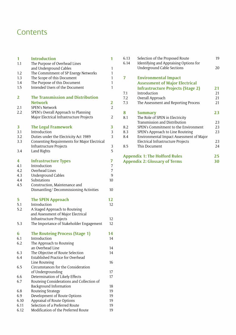
Electricity is an essential part of our everyday lives. We all expect to have access to it at the flick of a switch and we take its presence in our homes and workplaces for granted. Within the ScottishPower group of companies, SP Energy Networks (SPEN) is responsible for ensuring that supplies of electricity are provided to users through the electricity transmission and distribution system.
SPEN has a long history of taking its responsibilities to the public and the environment seriously. SPEN adopts a pro-active approach, balancing environmental considerations with the need to remain competitive and to provide services at a cost which customers can afford.
High voltage, high capacity overhead lines are the economic and reliable choice for the bulk transmission of electricity throughout the world. The routeing of overhead lines is a complex process, requiring a balance to be struck between statutory obligations, engineering requirements, economic viability, land use and the environment.
Major electrical infrastructure projects can understandably generate considerable public interest and debate, particularly in relation to local concerns such as visual amenity. However, given the importance of these projects to society as a whole, it is important that public debate is well-informed.
This document has been written to provide a better understanding, for all those involved in the consideration of major electrical infrastructure projects, of our approach to the routeing and environmental impact assessment of such projects and their associated infrastructure. Satisfying all SPEN’s duties can be challenging. In seeking to achieve this, SPEN recognises the importance of consulting effectively on proposals and of being transparent about the decisions that are made.
The document applies to major electrical infrastructure projects in Scotland, England and Wales, with reference made to any differences in legislative process.
Preface
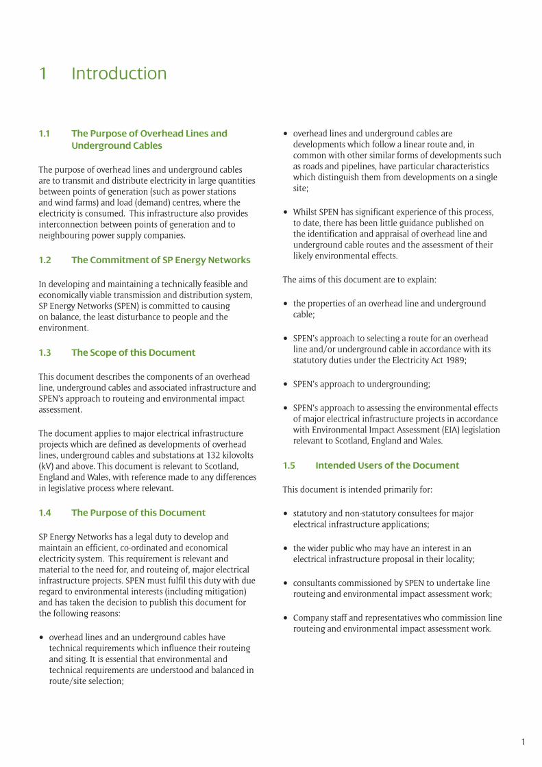
1 Introduction 11.1 The Purpose of Overhead Lines and Underground Cables 11.2 The Commitment of SP Energy Networks 11.3 The Scope of this Document 11.4 The Purpose of this Document 11.5 Intended Users of the Document 1
2 The Transmission and Distribution Network 22.1 SPEN’s Network 22.2 SPEN’s Overall Approach to Planning Major Electrical Infrastructure Projects 2
3 The Legal Framework 33.1 Introduction 33.2 Duties under the Electricity Act 1989 33.3 Consenting Requirements for Major Electrical Infrastructure Projects 33.4 Land Rights 5
4 Infrastructure Types 74.1 Introduction 74.2 Overhead Lines 74.3 Underground Cables 94.4 Substations 104.5 Construction, Maintenance and Dismantling/ Decommissioning Activities 10
5 The SPEN Approach 125.1 Introduction 125.2 A Staged Approach to Routeing and Assessment of Major Electrical Infrastructure Projects 125.3 The Importance of Stakeholder Engagement 12
6 The Routeing Process (Stage 1) 146.1 Introduction 146.2 The Approach to Routeing an Overhead Line 146.3 The Objective of Route Selection 146.4 Established Practice for Overhead Line Routeing 166.5 Circumstances for the Consideration of Undergrounding 176.6 Determination of Likely Effects 176.7 Routeing Considerations and Collection of Background Information 186.8 Routeing Strategy 196.9 Development of Route Options 196.10 Appraisal of Route Options 196.11 Selection of a Preferred Route 196.12 Modification of the Preferred Route 19
6.13 Selection of the Proposed Route 196.14 Identifying and Appraising Options for Underground Cable Sections 20
7 Environmental Impact Assessment of Major Electrical Infrastructure Projects (Stage 2) 217.1 Introduction 217.2 Overall Approach 217.3 The Assessment and Reporting Process 21
8 Summary 238.1 The Role of SPEN in Electricity Transmission and Distribution 238.2 SPEN’s Commitment to the Environment 238.3 SPEN’s Approach to Line Routeing 238.4 Environmental Impact Assessment of Major Electrical Infrastructure Projects 238.5 This Document 24
Appendix 1: The Holford Rules 25Appendix 2: Glossary of Terms 30
Contents
1
1.1 The Purpose of Overhead Lines and Underground Cables
The purpose of overhead lines and underground cables are to transmit and distribute electricity in large quantities between points of generation (such as power stations and wind farms) and load (demand) centres, where the electricity is consumed. This infrastructure also provides interconnection between points of generation and to neighbouring power supply companies.
1.2 The Commitment of SP Energy Networks
In developing and maintaining a technically feasible and economically viable transmission and distribution system, SP Energy Networks (SPEN) is committed to causing on balance, the least disturbance to people and the environment.
1.3 The Scope of this Document
This document describes the components of an overhead line, underground cables and associated infrastructure and SPEN’s approach to routeing and environmental impact assessment.
The document applies to major electrical infrastructure projects which are defined as developments of overhead lines, underground cables and substations at 132 kilovolts (kV) and above. This document is relevant to Scotland, England and Wales, with reference made to any differences in legislative process where relevant.
1.4 The Purpose of this Document
SP Energy Networks has a legal duty to develop and maintain an efficient, co-ordinated and economical electricity system. This requirement is relevant and material to the need for, and routeing of, major electrical infrastructure projects. SPEN must fulfil this duty with due regard to environmental interests (including mitigation) and has taken the decision to publish this document for the following reasons:
• overhead lines and an underground cables have technical requirements which influence their routeing and siting. It is essential that environmental and technical requirements are understood and balanced in route/site selection;
• overhead lines and underground cables are developments which follow a linear route and, in common with other similar forms of developments such as roads and pipelines, have particular characteristics which distinguish them from developments on a single site;
• Whilst SPEN has significant experience of this process, to date, there has been little guidance published on the identification and appraisal of overhead line and underground cable routes and the assessment of their likely environmental effects.
The aims of this document are to explain:
• the properties of an overhead line and underground cable;
• SPEN’s approach to selecting a route for an overhead line and/or underground cable in accordance with its statutory duties under the Electricity Act 1989;
• SPEN’s approach to undergrounding;
• SPEN’s approach to assessing the environmental effects of major electrical infrastructure projects in accordance with Environmental Impact Assessment (EIA) legislation relevant to Scotland, England and Wales.
1.5 Intended Users of the Document
This document is intended primarily for:
• statutory and non-statutory consultees for major electrical infrastructure applications;
• the wider public who may have an interest in an electrical infrastructure proposal in their locality;
• consultants commissioned by SPEN to undertake line routeing and environmental impact assessment work;
• Company staff and representatives who commission line routeing and environmental impact assessment work.
1 Introduction
2
2 The Transmission and Distribution Network
2.1 SPEN’s Network
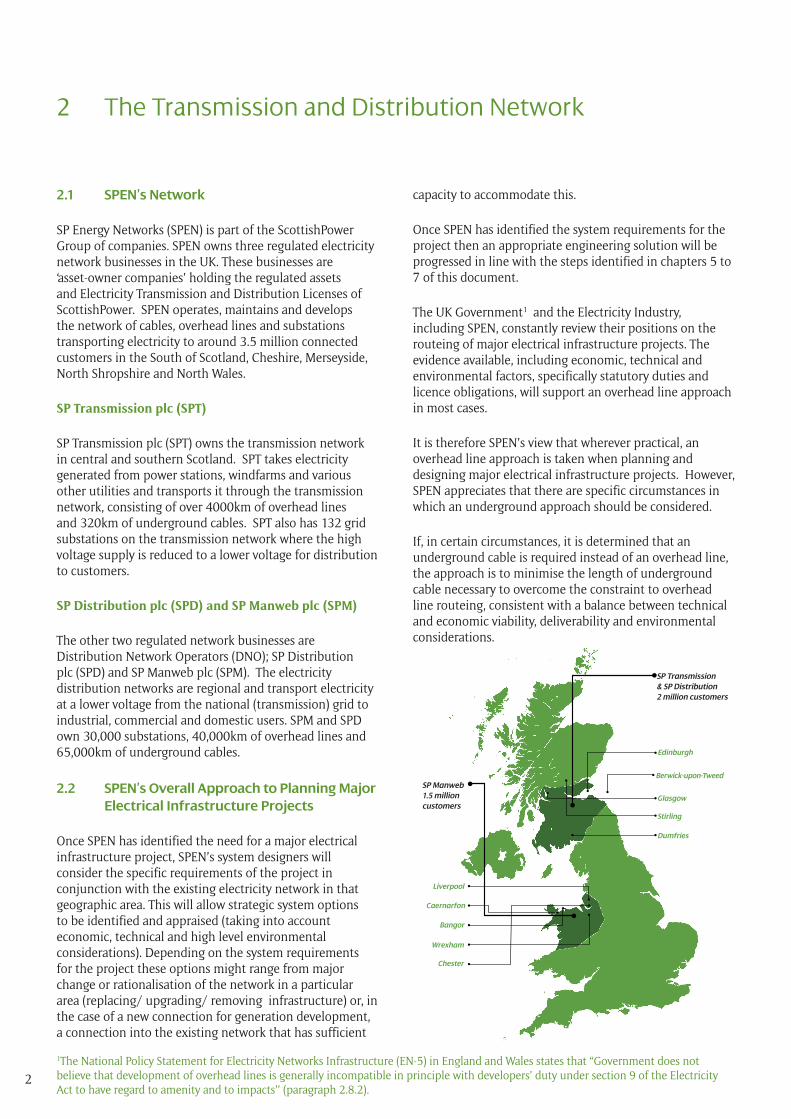
SP Energy Networks (SPEN) is part of the ScottishPower Group of companies. SPEN owns three regulated electricity network businesses in the UK. These businesses are ‘asset-owner companies’ holding the regulated assets and Electricity Transmission and Distribution Licenses of ScottishPower. SPEN operates, maintains and develops the network of cables, overhead lines and substations transporting electricity to around 3.5 million connected customers in the South of Scotland, Cheshire, Merseyside, North Shropshire and North Wales.
SP Transmission plc (SPT)
SP Transmission plc (SPT) owns the transmission network in central and southern Scotland. SPT takes electricity generated from power stations, windfarms and various other utilities and transports it through the transmission network, consisting of over 4000km of overhead lines and 320km of underground cables. SPT also has 132 grid substations on the transmission network where the high voltage supply is reduced to a lower voltage for distribution to customers.
SP Distribution plc (SPD) and SP Manweb plc (SPM)
The other two regulated network businesses are Distribution Network Operators (DNO); SP Distribution plc (SPD) and SP Manweb plc (SPM). The electricity distribution networks are regional and transport electricity at a lower voltage from the national (transmission) grid to industrial, commercial and domestic users. SPM and SPD own 30,000 substations, 40,000km of overhead lines and 65,000km of underground cables.
2.2 SPEN’s Overall Approach to Planning Major Electrical Infrastructure Projects
Once SPEN has identified the need for a major electrical infrastructure project, SPEN’s system designers will consider the specific requirements of the project in conjunction with the existing electricity network in that geographic area. This will allow strategic system options to be identified and appraised (taking into account economic, technical and high level environmental considerations). Depending on the system requirements for the project these options might range from major change or rationalisation of the network in a particular area (replacing/ upgrading/ removing infrastructure) or, in the case of a new connection for generation development, a connection into the existing network that has sufficient
capacity to accommodate this.
Once SPEN has identified the system requirements for the project then an appropriate engineering solution will be progressed in line with the steps identified in chapters 5 to 7 of this document.
The UK Government1 and the Electricity Industry, including SPEN, constantly review their positions on the routeing of major electrical infrastructure projects. The evidence available, including economic, technical and environmental factors, specifically statutory duties and licence obligations, will support an overhead line approach in most cases.
It is therefore SPEN’s view that wherever practical, an overhead line approach is taken when planning and designing major electrical infrastructure projects. However, SPEN appreciates that there are specific circumstances in which an underground approach should be considered.
If, in certain circumstances, it is determined that an underground cable is required instead of an overhead line, the approach is to minimise the length of underground cable necessary to overcome the constraint to overhead line routeing, consistent with a balance between technical and economic viability, deliverability and environmental considerations.
1The National Policy Statement for Electricity Networks Infrastructure (EN-5) in England and Wales states that “Government does not believe that development of overhead lines is generally incompatible in principle with developers’ duty under section 9 of the Electricity Act to have regard to amenity and to impacts’’ (paragraph 2.8.2).
Edinburgh
Berwick-upon-Tweed
Glasgow
Stirling
Dumfries
Liverpool
Caernarfon
Bangor
Wrexham
Chester
SP Manweb 1.5 million customers
SP Transmission & SP Distribution 2 million customers
3
3 The Legal Framework
3.1 Introduction
There are a number of legal provisions which apply to the development of electricity transmission and distribution lines and associated infrastructure.
The principal legislation which applies in the UK is the Electricity Act 1989. SPEN is also subject to the requirements of ‘the Planning System’. Scotland has a different planning system to England and Wales and, as a consequence, consenting requirements differ from those in England and Wales, as explained below.
The European Union, under Directive 2011/92/EU, also requires that member states ensure certain types of development are assessed in terms of their impact upon the environment.
3.2 Duties under the Electricity Act 1989
The Electricity Act 1989 provided for the privatisation of the electricity supply industry in the UK and established a licensing regime and a regulator for the industry. SPEN’s licensed businesses are authorised to transmit and distribute electricity within its network areas. As such, the Company has a statutory obligation to carry out the duties outlined within the Electricity Act.
Section 9 of the Electricity Act states that it shall be the duty of a license holder ‘‘to develop and maintain an efficient, co-ordinated and economical system of electricity transmission/ distribution’’.
Schedule 9 of the Electricity Act requires SPEN to take account of specific factors in formulating any relevant proposals. This provides that SPEN must:
‘‘have regard to the desirability of preserving natural beauty, of conserving flora, fauna and geological or physiographical features of special interest and of protecting sites, buildings and objects of architectural, historic or archaeological interest; and, to do what he reasonably can to mitigate any effect which the proposals would have on the natural beauty of the countryside or on any such flora, fauna, features, sites, buildings or objects,’’
3.3 Consenting Requirements for Major Electrical Infrastructure Projects
Consenting Requirements in Scotland
Section 37 of the Electricity Act requires that, with the exception of certain specific examples, all electricity lines exceeding 20kV will require consent to be granted by the Scottish Ministers. This ‘section 37 consent’ gives approval to install, and keep installed, an overhead electricity line. Section 57 of the Town & Country Planning (Scotland) Act 1997 as amended by The Planning Etc (Scotland) Act 2006 provides that ‘‘Planning permission may also be deemed to be granted in the case of development with government authorisation’’.
In certain circumstances, deemed planning permission may also include works that are ‘ancillary’ or necessary to the operation of the overhead line such as cable sealing and compounds. In some instances, there may also be the need for separate planning permission where development does not form part of a section 37 application. For example, separate planning permission may be required for ‘ancillary development’ such as a substation. Where consent for development is sought, an application must be made to the relevant planning authority, under the Town & Country Planning (Scotland) Act 1997 as amended by The Planning Etc (Scotland) Act 2006, before such works are able to be carried out.
4
All development requires planning permission. However, some forms of development, including underground cables, are classed as ‘permitted development’ under the Town and Country Planning (General Permitted Development) (Scotland) Order 1992 (as amended). Developments classified as permitted development may automatically be granted planning permission, by statutory order, and do not require submission of a planning application to the local planning authority. Any sealing end compounds required at the point of transition between overhead lines and underground cables may require planning permission from the relevant planning authority.
Consenting Requirements in England and Wales
The Planning Act 2008 is a consolidation of earlier planning legislation in England and Wales. This Act sets out thresholds for the determination of Nationally Significant Infrastructure Projects (NSIPs). NSIPs are usually large scale developments which require a type of consent known as a ‘Development Consent Order’ (DCO) under procedures governed by the Planning Act 2008 (and amended by the Localism Act 2011).
In England and Wales, an overhead line of the voltage considered in this document falls under the definition of a ‘Nationally Significant Infrastructure Project (NSIP)’ by virtue of being an above ground electric line with a voltage of 132kV or greater (Part 3, Section 16 of the Planning Act 2008, as amended by The Overhead Lines (Exempt Installations) Order 2010). As such, an application for a DCO must be submitted to the Planning Inspectorate who will examine the application and issue a recommendation to the Secretary of State, who makes the final decision whether to grant or refuse development consent. A granted DCO may also cover any underground cable sections that may be required.
In England, deemed planning permission can be granted under the DCO for ancillary development such as cable sealing ends. In Wales, associated development requires separate planning permission from the local planning authority.
All development requires planning permission. However, some forms of development, including underground cables, are classed as ‘permitted development’ under the Town and Country Planning (General Permitted Development) (England) Order 2015 and the Town and Country Planning (General Permitted Development)(Amendment)(Wales) Order 2014. Developments classified as permitted development may automatically be granted
planning permission, by statutory order, and do not require submission of a planning application to the local planning authority.
Environmental Impact Assessment
The European Union, under Directive 2011/92/EU, requires that member states ensure certain types of development are assessed in terms of their impact upon the environment (‘environmental impact assessment’ (EIA)). Member states are required to adopt amendments to this Directive, which are outlined in Directive 2014/52/EU, by the year 2017.
Under the provisions of the EIA Directive, consent cannot be given for any ‘EIA development’ unless the consenting authority has considered environmental information, in accordance with the requirements of the Directive. Overhead lines of the type considered in this document commonly constitute EIA development by virtue of their voltage and/or their length, which means that significant effects on the environment are considered likely. These developments require an EIA to be undertaken and an Environmental Statement to be produced and submitted with the relevant consent application. Any sections of underground cable deemed necessary are included within the EIA as associated or ancillary development.
In Scotland, the relevant EIA requirements are contained in the Electricity Works (Environmental Impact Assessment)(Scotland) Regulations 2000.
In England and Wales, the relevant EIA requirements are
5
contained in the Infrastructure Planning (Environmental Impact Assessment) Regulations 2009 (as amended).
Importantly, if a planning authority deems that a development requires EIA, in accordance with EIA Regulations, any permitted development rights are withdrawn and a planning application must be submitted and accompanied by an Environmental Statement.
After careful consideration of both the nature and scale of development, SPEN, through its consenting team, may determine that some level of Environmental Report will be required, although the development itself may not constitute an ‘EIA Development’.
3.4 Land Rights
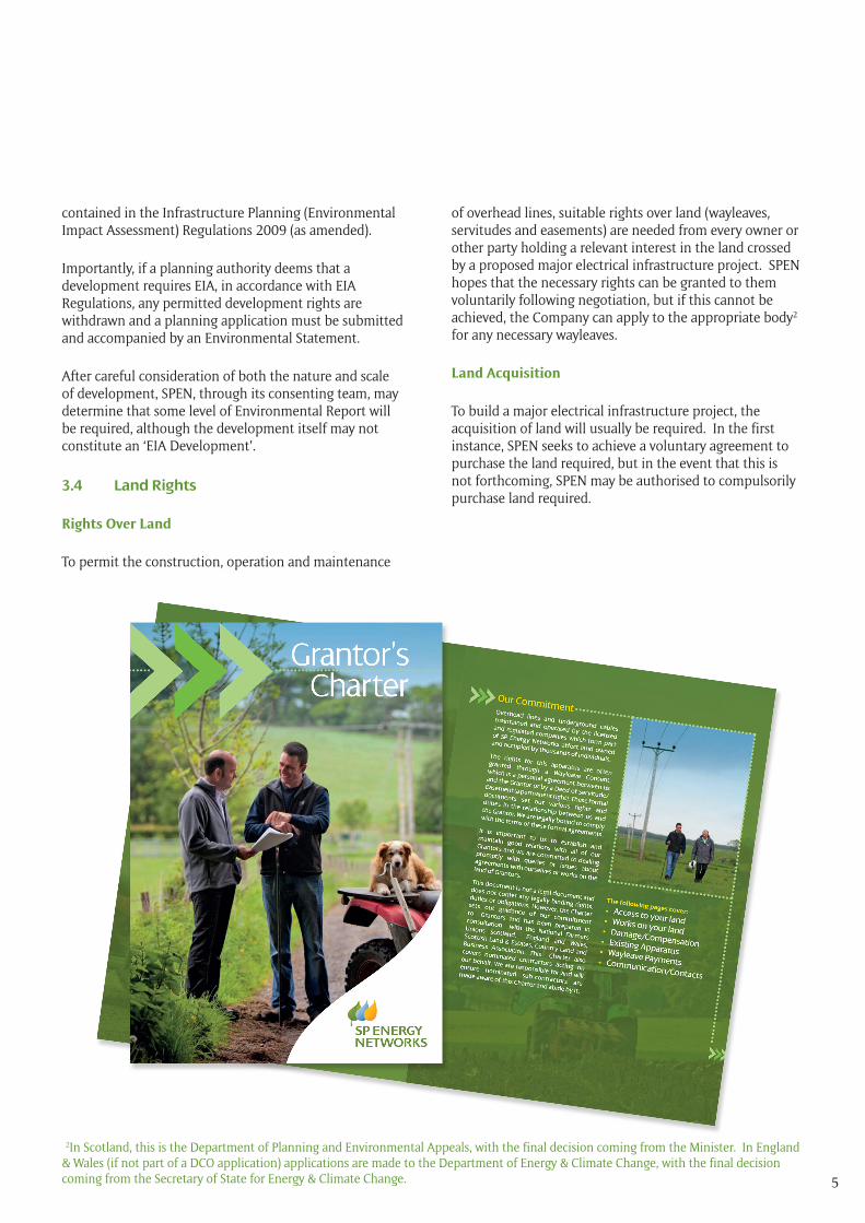
Rights Over Land
To permit the construction, operation and maintenance
of overhead lines, suitable rights over land (wayleaves, servitudes and easements) are needed from every owner or other party holding a relevant interest in the land crossed by a proposed major electrical infrastructure project. SPEN hopes that the necessary rights can be granted to them voluntarily following negotiation, but if this cannot be achieved, the Company can apply to the appropriate body2 for any necessary wayleaves.
Land Acquisition
To build a major electrical infrastructure project, the acquisition of land will usually be required. In the first instance, SPEN seeks to achieve a voluntary agreement to purchase the land required, but in the event that this is not forthcoming, SPEN may be authorised to compulsorily purchase land required.
2In Scotland, this is the Department of Planning and Environmental Appeals, with the final decision coming from the Minister. In England & Wales (if not part of a DCO application) applications are made to the Department of Energy & Climate Change, with the final decision coming from the Secretary of State for Energy & Climate Change.
6
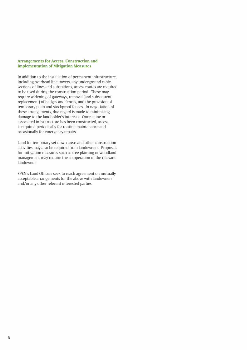
Arrangements for Access, Construction and Implementation of Mitigation Measures
In addition to the installation of permanent infrastructure, including overhead line towers, any underground cable sections of lines and substations, access routes are required to be used during the construction period. These may require widening of gateways, removal (and subsequent replacement) of hedges and fences, and the provision of temporary plain and stockproof fences. In negotiation of these arrangements, due regard is made to minimising damage to the landholder’s interests. Once a line or associated infrastructure has been constructed, access is required periodically for routine maintenance and occasionally for emergency repairs.
Land for temporary set-down areas and other construction activities may also be required from landowners. Proposals for mitigation measures such as tree planting or woodland management may require the co-operation of the relevant landowner.
SPEN’s Land Officers seek to reach agreement on mutually acceptable arrangements for the above with landowners and/or any other relevant interested parties.
7
4 Infrastructure Types
4.1 Introduction
Electricity is transmitted at 132kV, 275kV or 400kV from the point of generation (such as a power station or wind farm) to an electricity substation. Electricity is transmitted in an alternating current (AC) system along either overhead lines or underground cables. At the electricity substation, the power is either transmitted on to another substation, or transformed to a lower voltage and distributed through the distribution network to customers.
4.2 Overhead Lines
With an overhead line, conductors (or wires) are suspended at a specified height above ground and supported by wooden poles or lattice steel towers, spaced at intervals. Conductors can be made either of aluminium or steel strands. Most overhead lines at 132 kV and above carry two 3-phase circuits (i.e. six conductors), with one circuit strung on each side of a tower. An earth wire may be required to provide lightning protection. Single circuit lines are used on occasion, and at 132kV, these lines can be supported on wooden poles.
Conductors are strung from insulators attached to the lower cross-arms or pole steel work and prevent the electric current from crossing to the tower or pole body.
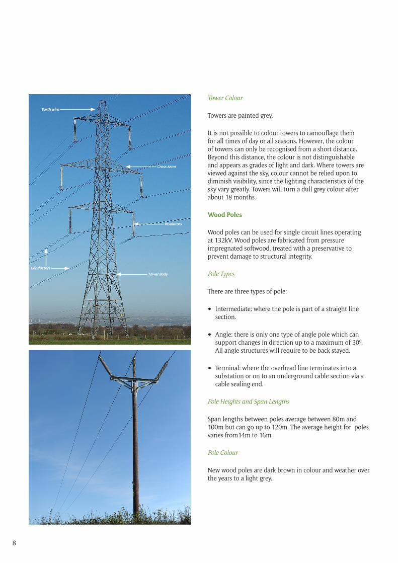
Towers
Towers can be used to carry conductors at 132kV and above. These are generally of a steel lattice construction fabricated from high tensile steel which is assembled using galvanised high tensile steel bolts with nuts and locking devices.
Tower Types
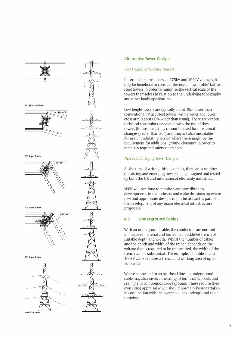
There are three types of tower:
• Suspension or Line: where the tower is part of a straight line section.
• Tension or Angle: where there is a horizontal or vertical deviation in line direction of a specified number of degrees. There are three main types of angle tower 30o , 60o and 90o.
• Terminal: where the overhead line terminates into a substation or on to an underground cable section via a separate cable sealing end compound or platform.
Tower Heights and Span Lengths
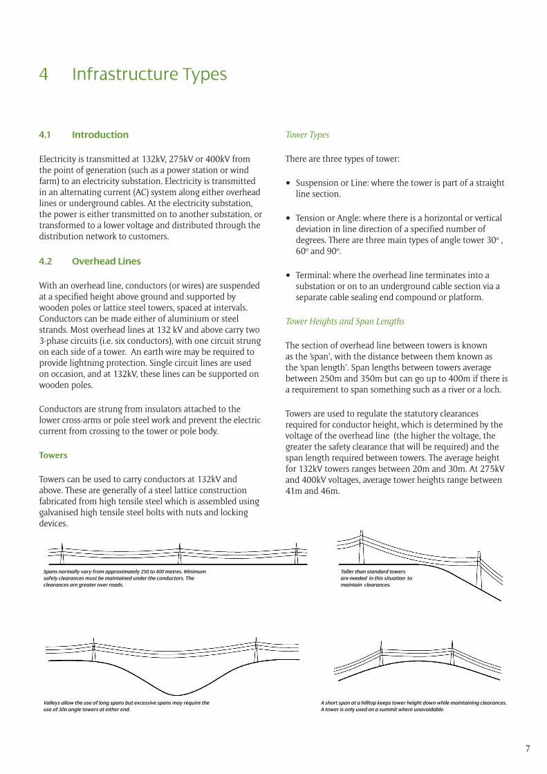
The section of overhead line between towers is known as the ‘span’, with the distance between them known as the ‘span length’. Span lengths between towers average between 250m and 350m but can go up to 400m if there is a requirement to span something such as a river or a loch.
Towers are used to regulate the statutory clearances required for conductor height, which is determined by the voltage of the overhead line (the higher the voltage, the greater the safety clearance that will be required) and the span length required between towers. The average height for 132kV towers ranges between 20m and 30m. At 275kV and 400kV voltages, average tower heights range between 41m and 46m.
Spans normally vary from approximately 250 to 400 metres. Minimum safely clearances must be maintained under the conductors. The clearances are greater over roads.
Valleys allow the use of long spans but excessive spans may require the use of 30o angle towers at either end.
Taller than standard towers are needed in this situation to maintain clearances.
A short span at a hilltop keeps tower height down while maintaining clearances. A tower is only used on a summit where unavoidable.
8
Tower Colour
Towers are painted grey.
It is not possible to colour towers to camouflage them for all times of day or all seasons. However, the colour of towers can only be recognised from a short distance. Beyond this distance, the colour is not distinguishable and appears as grades of light and dark. Where towers are viewed against the sky, colour cannot be relied upon to diminish visibility, since the lighting characteristics of the sky vary greatly. Towers will turn a dull grey colour after about 18 months.
Wood Poles
Wood poles can be used for single circuit lines operating at 132kV. Wood poles are fabricated from pressure impregnated softwood, treated with a preservative to prevent damage to structural integrity.
Pole Types
There are three types of pole:
• Intermediate: where the pole is part of a straight line section.
• Angle: there is only one type of angle pole which can support changes in direction up to a maximum of 300. All angle structures will require to be back stayed.
• Terminal: where the overhead line terminates into a substation or on to an underground cable section via a cable sealing end.
Pole Heights and Span Lengths
Span lengths between poles average between 80m and 100m but can go up to 120m. The average height for poles varies from14m to 16m.
Pole Colour
New wood poles are dark brown in colour and weather over the years to a light grey.
Earth wire
Cross Arms
Insulators
Tower Body
Conductors
9
Alternative Tower Designs
Low Height Lattice Steel Towers
In certain circumstances, at 275kV and 400kV voltages, it may be beneficial to consider the use of ‘low profile’ lattice steel towers in order to minimise the vertical scale of the towers themselves in relation to the underlying topography and other landscape features.
Low height towers are typically about 10m lower than conventional lattice steel towers, with a wider and lower cross arm (about 60% wider than usual). There are various technical constraints associated with the use of these towers (for instance, they cannot be used for directional changes greater than 30 °) and they are also unsuitable for use in undulating terrain where there might be the requirement for additional ground clearance in order to maintain required safety clearances.
New and Emerging Tower Designs
At the time of writing this document, there are a number of existing and emerging towers being designed and tested by both the UK and international electricity industries.
SPEN will continue to monitor, and contribute to, developments in the industry and make decisions on where new and appropriate designs might be utilised as part of the development of any major electrical infrastructure proposals.
4.3 Underground Cables
With an underground cable, the conductors are encased in insulated material and buried in a backfilled trench of suitable depth and width. Whilst the number of cables, and the depth and width of the trench depends on the voltage that is required to be transmitted, the width of the trench can be substantial. For example, a double circuit 400kV cable requires a trench and working area of up to 30m wide.
Where connected to an overhead line, an underground cable may also involve the siting of terminal supports and sealing end compounds above ground. These require their own siting appraisal which should normally be undertaken in conjunction with the overhead line/underground cable routeing.
Straight Line Tower
30º Angle Tower
60º Angle Tower
90º Angle Tower
Terminal Tower
Up to 30º
30º-60º
60º-90º
10
4.4 Substations
Substations generally contain switching, protection and control equipment and ‘transformers’ which are used to increase or decrease the voltage of electricity. Equipment is commonly located both within a purpose built building and outside the building in a fenced enclosure or ‘compound’. The size of the substation depends on the voltage of the electricity being transformed.
4.5 Construction, Maintenance and Dismantling/Decommissioning Activities
Introduction
The construction of overhead lines, underground cables and substations requires additional temporary infrastructure such as temporary accesses to tower/pole locations and to cable trenches and construction compounds to store materials. All have limited maintenance requirements and all are subject to well-established procedures for dismantling/decommissioning.
Overhead Lines
Line construction, maintenance and decommissioning usually follow a standard sequence of activities. The duration of these activities for wood pole lines is normally less than for lattice steel tower lines.
The total duration of construction activity at any single tower site is approximately two weeks for tower foundations, one to two weeks for tower construction, and up to four weeks for conductor erection and stringing depending on the size of the tower and the number of the conductors to be strung. These periods are spread over about four months, with periods of inactivity between, or longer if construction difficulties are experienced elsewhere along the line or ground conditions prevent normal progress. The construction period for the construction of wood pole lines is normally less than for tower lines.
Prior to constructing the overhead line, temporary accesses will be constructed, as necessary, and laydown /storage areas established, usually mid-way along the route. Any trees which may impact on safety clearances will be removed or lopped. Following commissioning of the overhead line, all equipment and temporary access of construction areas will be remained with the land being reinstated to the satisfaction of the landowner.
The majority of overhead line components are maintenance free, although periodic painting of the tower steelwork may be required and components are regularly inspected for corrosion, wear and deterioration. There is also an ongoing requirement to ensure that any trees within the wayleave corridor do not impact on safety clearances.
The condition of tower steelwork and foundations is monitored regularly. Towers which have deteriorated significantly may be dismantled carefully and replaced. If a line is decommissioned, towers will be removed with components re-used where possible. Foundations are removed to a minimum depth of one metre below ground level, the area cleared and the ground reinstated.
Underground Cables
Open cut trenching is the most frequently used construction method for cable installation. However, in crossing under watercourses or motorways for example, a trenchless technique such as directional drilling may be used. Works at each section commonly consist of the construction of a haul road, the excavation of the cable trench by mechanical excavators, cable laying, the backfilling of the trench with sand and native material and surface reinstatement. A typical cable installation rate is up to 160m per week, depending on the terrain, a temporary construction compound is also required and again this is generally located close to the midpoint of the cable route.
Sections of cable are joined together at cable jointing pits, with the location of these dictated by a number of factors including cable size/length and ongoing access requirements. Manhole covers above jointing pits enable access just below the surface for routine maintenance. Underground cables are marked on services maps provided to other utilities and are installed with marker tape to warn of their presence below the ground.
Annual maintenance checks on foot are commonly required during operation. The cable route will also be kept clear of all but low growing vegetation. In the unlikely event that there is a fault along the cable, the area around the fault is excavated and the fault repaired or a new section of cable inserted as a replacement.
If lines are decommissioned, cables can either be left in situ or removed carefully by opening up the ground.
11
Substations
To construct a substation, an additional temporary area is commonly needed for off-loading and storing materials, parking and welfare facilities. The first stages of standard construction procedures involve removing the top ground surface layer, levelling and consolidating the ground, establishing a copper earthing mat and equipment foundations, compacting, surfacing and establishing drainage systems. Cable routes and internal access routes are then established, followed by the construction of necessary control buildings, additional external and internal components and finally cable installation. Following testing and commissioning works, reinstatement and landscaping works will be carried out as necessary. A security fence will also be erected around the perimeter of the site and appropriate safety warning signs posted.
Substations are not permanently manned or lit but inspection visits are undertaken regularly.
Substation decommissioning works involve the removal of above ground infrastructure and hardstanding for recycling/disposal off site. As required, the site will then be re-profiled to the level existing prior to construction.
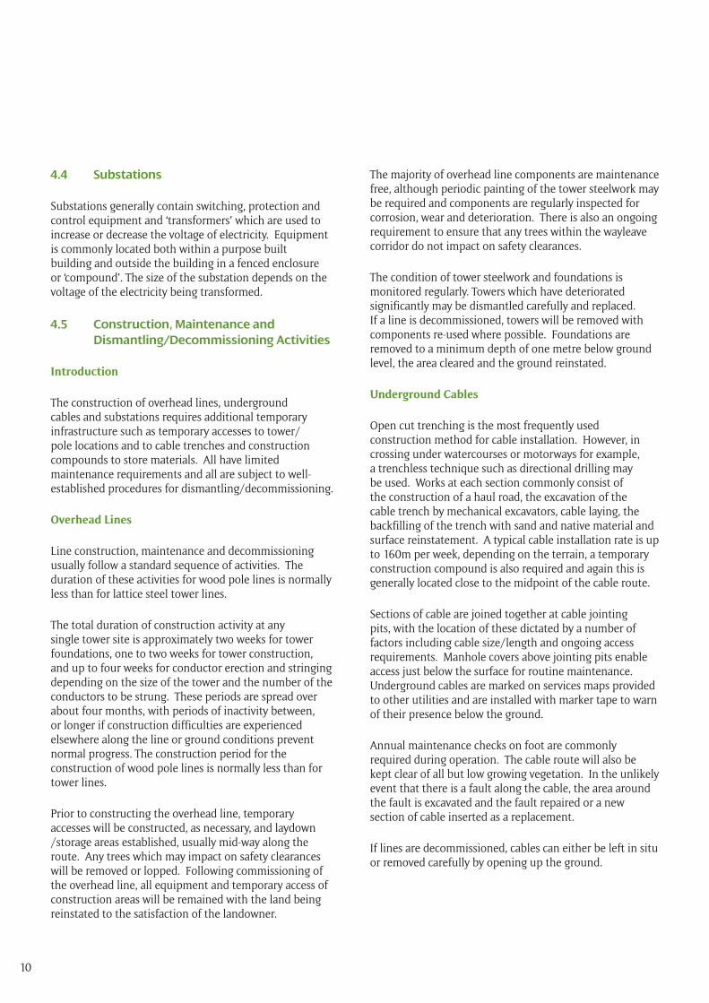
Tower under construction
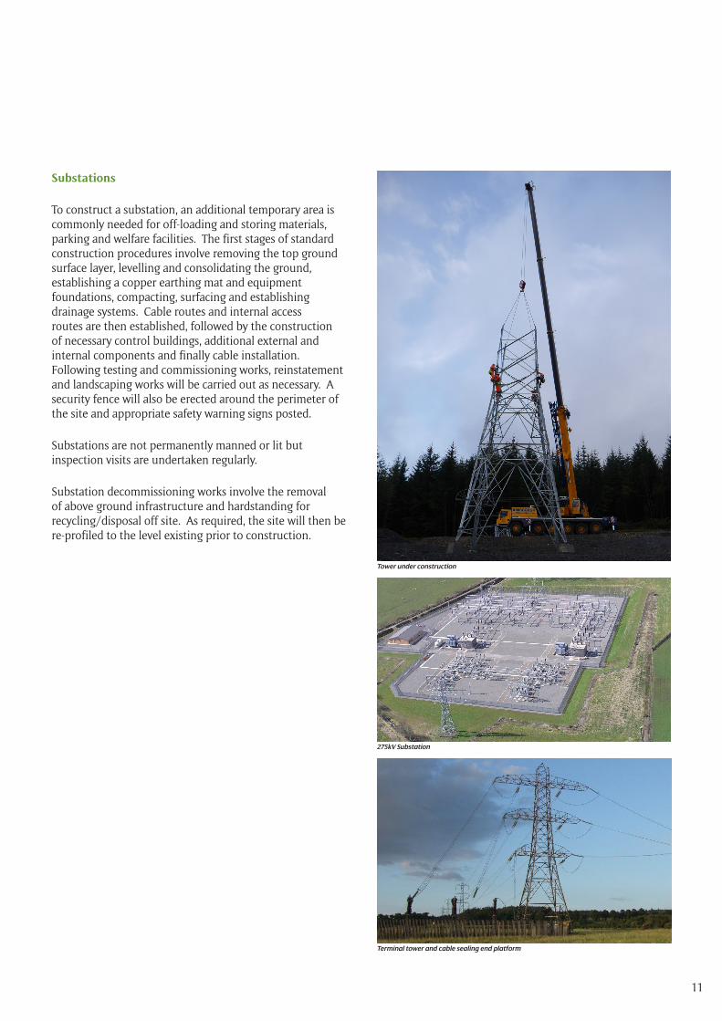
275kV Substation
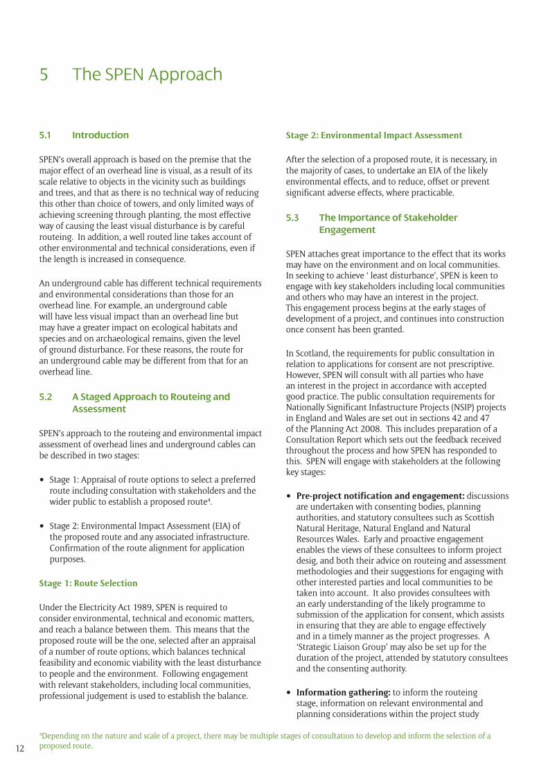
Terminal tower and cable sealing end platform
12
5 The SPEN Approach
5.1 Introduction
SPEN’s overall approach is based on the premise that the major effect of an overhead line is visual, as a result of its scale relative to objects in the vicinity such as buildings and trees, and that as there is no technical way of reducing this other than choice of towers, and only limited ways of achieving screening through planting, the most effective way of causing the least visual disturbance is by careful routeing. In addition, a well routed line takes account of other environmental and technical considerations, even if the length is increased in consequence.
An underground cable has different technical requirements and environmental considerations than those for an overhead line. For example, an underground cable will have less visual impact than an overhead line but may have a greater impact on ecological habitats and species and on archaeological remains, given the level of ground disturbance. For these reasons, the route for an underground cable may be different from that for an overhead line.
5.2 A Staged Approach to Routeing and Assessment
SPEN’s approach to the routeing and environmental impact assessment of overhead lines and underground cables can be described in two stages:
• Stage 1: Appraisal of route options to select a preferred route including consultation with stakeholders and the wider public to establish a proposed route4.
• Stage 2: Environmental Impact Assessment (EIA) of the proposed route and any associated infrastructure.Confirmation of the route alignment for application purposes.
Stage 1: Route Selection
Under the Electricity Act 1989, SPEN is required to consider environmental, technical and economic matters, and reach a balance between them. This means that the proposed route will be the one, selected after an appraisal of a number of route options, which balances technical feasibility and economic viability with the least disturbance to people and the environment. Following engagement with relevant stakeholders, including local communities, professional judgement is used to establish the balance.
Stage 2: Environmental Impact Assessment
After the selection of a proposed route, it is necessary, in the majority of cases, to undertake an EIA of the likely environmental effects, and to reduce, offset or prevent significant adverse effects, where practicable.
5.3 The Importance of Stakeholder Engagement
SPEN attaches great importance to the effect that its works may have on the environment and on local communities. In seeking to achieve ‘ least disturbance’, SPEN is keen to engage with key stakeholders including local communities and others who may have an interest in the project. This engagement process begins at the early stages of development of a project, and continues into construction once consent has been granted.
In Scotland, the requirements for public consultation in relation to applications for consent are not prescriptive. However, SPEN will consult with all parties who have an interest in the project in accordance with accepted good practice. The public consultation requirements for Nationally Significant Infastructure Projects (NSIP) projects in England and Wales are set out in sections 42 and 47 of the Planning Act 2008. This includes preparation of a Consultation Report which sets out the feedback received throughout the process and how SPEN has responded to this. SPEN will engage with stakeholders at the following key stages:
• Pre-project notification and engagement: discussions are undertaken with consenting bodies, planning authorities, and statutory consultees such as Scottish Natural Heritage, Natural England and Natural Resources Wales. Early and proactive engagement enables the views of these consultees to inform project desig, and both their advice on routeing and assessment methodologies and their suggestions for engaging with other interested parties and local communities to be taken into account. It also provides consultees with an early understanding of the likely programme to submission of the application for consent, which assists in ensuring that they are able to engage effectively and in a timely manner as the project progresses. A ‘Strategic Liaison Group’ may also be set up for the duration of the project, attended by statutory consultees and the consenting authority.
• Information gathering: to inform the routeing stage, information on relevant environmental and planning considerations within the project study
4Depending on the nature and scale of a project, there may be multiple stages of consultation to develop and inform the selection of a proposed route.
13
area is requested from statutory consultees and other relevant organisations such as the Royal Society for the Protection of Birds and local Wildlife Trusts. In conjunction with this, or in parallel, consultation may be undertaken to gather feedback on proposed data gathering techniques (such as seasonal bird surveys) for comparing alternative corridors and line routes.
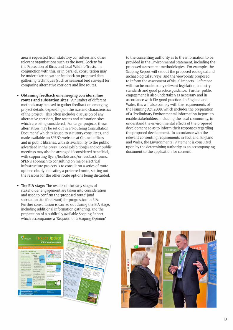
• Obtaining feedback on emerging corridors, line routes and substation sites: A number of different methods may be used to gather feedback on emerging project details, depending on the size and characteristics of the project. This often includes discussion of any alternative corridors, line routes and substation sites which are being considered. For larger projects, these alternatives may be set out in a ‘Routeing Consultation Document’ which is issued to statutory consultees, and made available on SPEN’s website, at Council offices and in public libraries, with its availability to the public advertised in the press. Local exhibition(s) and/or public meetings may also be arranged if considered beneficial, with supporting flyers/leaflets and/or feedback forms. SPEN’s approach to consulting on major electrical infrastructure projects is to consult on a series of route options clearly indicating a preferred route, setting out the reasons for the other route options being discarded.
• The EIA stage: The results of the early stages of stakeholder engagement are taken into consideration and used to confirm the ‘proposed route’ (and substation site if relevant) for progression to EIA. Further consultation is carried out during the EIA stage, including additional information gathering, and the preparation of a publically available Scoping Report which accompanies a ‘Request for a Scoping Opinion’
to the consenting authority as to the information to be provided in the Environmental Statement, including the proposed assessment methodologies. For example, the Scoping Report will set out the proposed ecological and archaeological surveys, and the viewpoints proposed to inform the assessment of visual impacts. Reference will also be made to any relevant legislation, industry standards and good practice guidance. Further public engagement is also undertaken as necessary and in accordance with EIA good practice. In England and Wales, this will also comply with the requirements of the Planning Act 2008, which includes the preparation of a ‘Preliminary Environmental Information Report’ to enable stakeholders, including the local community, to understand the environmental effects of the proposed development so as to inform their responses regarding the proposed development. In accordance with the relevant consenting requirements in Scotland, England and Wales, the Environmental Statement is consulted upon by the determining authority as an accompanying document to the application for consent.
14
6.1 Introduction
This chapter describes the process which SPEN follows to select a proposed route for an overhead line and/or an underground cable. This process is important because the most effective method of causing ‘least disturbance’ is by careful routeing.
Having established the need for a project, the starting point is always to identify an overhead line route. If an underground cable is required for a section of an overhead line route, the objective is to minimise the length of underground cable necessary to overcome the constraint to overhead line routeing, consistent with a balance between technical, economic viability, and environmental considerations.
6.2 The Approach to Routeing an Overhead Line
The approach to routeing an overhead line is based on the premise that the major effect of an overhead line is visual and that the degree of visual intrusion can be reduced by careful routeing. A reduction in visual intrusion can be achieved by routeing the line to fit the topography, by using topography and trees to provide screening and/or background, and by routeing the line at a distance from settlements and roads. In addition, a well-routed line takes into account other environmental and technical considerations and will avoid, wherever possible, the most sensitive and valued natural and man-made features.
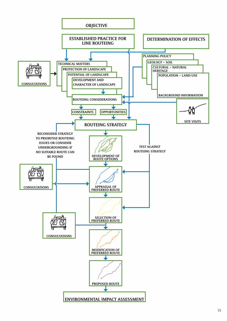
Every project broadly follows the well-established and sequential step-by-step process outlined below and summarised in the flow diagram overleaf:
• objective of route selection;
• established practice for overhead line routeing;
• determination of likely effects;
• routeing considerations/collection of background information;
• routeing strategy;
• development of route options;
• appraisal of route options;
• selection of the preferred route;
• modification of the preferred route;
• selection of the proposed route;
Whilst presented as a linear process for simplicity, the approach is iterative and the steps may be re-visited several times. The outcome of each step is subject to a technical and, where relevant, consultation, ‘check’ with key stakeholders and the public, prior to commencing the next step. Professional judgement is used to establish explicitly the balance between technical, economic and environmental factors.
Each of the steps is described below.
6.3 The Objective of Route Selection
The objective of route selection is to identify a technically feasible and economically viable overhead line route, between specified points, which causes the least disturbance to people and the environment.
Key features of the approach are as follows:
• follow an iterative procedure;
• engage with stakeholders;
• establish a balance between engineering requirements, economic viability, land use and the environment;
6 The Routeing Process (Stage 1)
15
RECONSIDER STRATEGY TO PRIORITISE ROUTEING
ISSUES OR CONSIDER UNDERGROUNDING IF
NO SUITABLE ROUTE CAN BE FOUND
TEST AGAINST ROUTEING STRATEGY
OBJECTIVE
ESTABLISHED PRACTICE FOR LINE ROUTEING
CONSULTATIONS
SITE VISITS
POPULATION + LAND USE
BACKGROUND INFORMATION
PLANNING POLICY
TECHNICAL MATTERS
PROTECTION OF LANDSCAPE
POTENTIAL OF LANDSCAPE
DEVELOPMENT AND CHARACTER OF LANDSCAPE
ROUTEING CONSIDERATIONS
CONSTRAINTS OPPORTUNITIES
ROUTEING STRATEGY
CONSULTATIONS
DEVELOPMENT OF ROUTE OPTIONS
APPRAISAL OF PREFERRED ROUTE
SELECTION OF PREFERRED ROUTE
MODIFICATION OF PREFERRED ROUTE
PROPOSED ROUTE
ENVIRONMENTAL IMPACT ASSESSMENT
GEOLOGY + SOILCULTURAL + NATURAL HERITAGE
DETERMINATION OF EFFECTS
CONSULTATIONS
16
6.4 Established Practice for Overhead Line Routeing
The Holford Rules
It is generally accepted across the electricity industry that the guidelines developed by the late Lord Holford in 1959 for routeing overhead lines, ‘The Holford Rules’, should continue to be employed as the basis for routeing high voltage overhead lines. The Holford Rules were reviewed circa 1992 by the National Grid Company (NGC) Plc. (now National Grid Transmission (NGT)) as owner and operator of the electricity transmission network in England and Wales, with notes of clarification added to update the Rules. A subsequent review of the Holford Rules (and NGC clarification notes) was undertaken by Scottish Hydro Electric Transmission Limited (SHETL) in 2003 to reflect Scottish circumstances. The Holford Rules also include Supplementary Notes on the Siting of Substations.
Rule 1
Avoid altogether, if possible, the major areas of highest amenity value*, by so planning the general route of the line in the first place, even if the total mileage is somewhat increased in consequence.
Rule 2
Avoid smaller areas of high amenity value, or scientific interest by deviation; provided that this can be done without using too many angle towers, i.e. the more massive structures which are used when lines change direction.
Rule 3
Other things being equal, choose the most direct line, with no sharp changes of direction and thus with few angle towers.
Rule 4
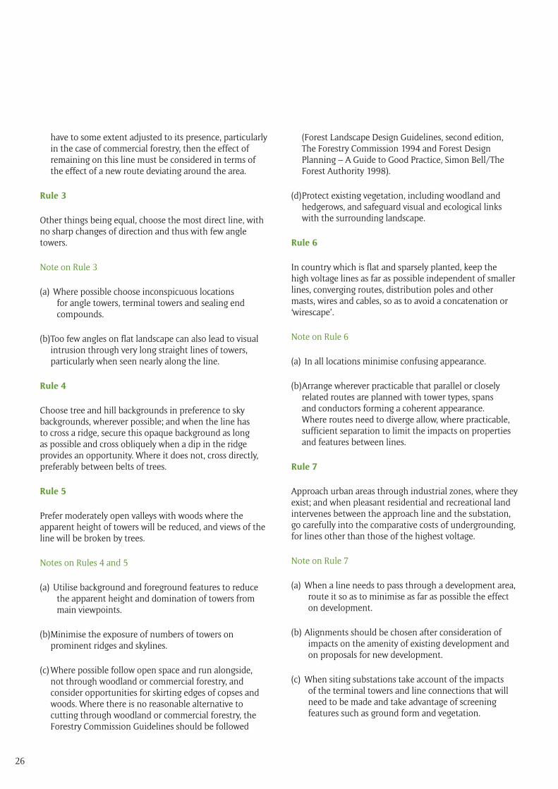
Choose tree and hill backgrounds in preference to sky backgrounds, wherever possible; and when the line has to cross a ridge, secure this opaque background as long as possible and cross obliquely when a dip in the ridge provides an opportunity. Where it does not, cross directly, preferably between belts of trees.
Rule 5
Prefer moderately open valleys with woods where the apparent height of towers will be reduced, and views of the line will be broken by trees.
Rule 6
In country which is flat and sparsely planted, keep the high voltage lines as far as possible independent of smaller lines, converging routes, distribution poles and other masts, wires and cables, so as to avoid a concatenation or ‘wirescape’.
Rule 7
Approach urban areas through industrial zones, where they exist; and when pleasant residential and recreational land intervenes between the approach line and the substation, go carefully into the comparative costs of undergrounding, for lines other than those of the highest voltage.
*often interpreted now as ‘environmental’ value to reflect wider intrinsic value
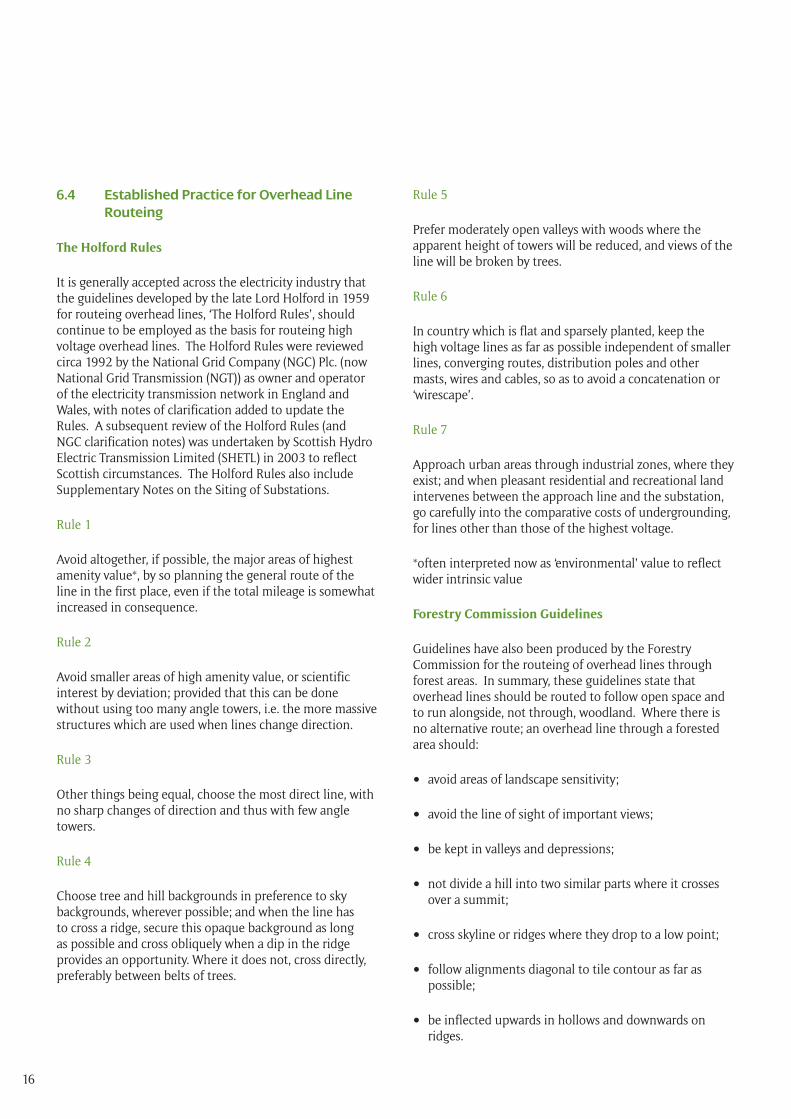
Forestry Commission Guidelines
Guidelines have also been produced by the Forestry Commission for the routeing of overhead lines through forest areas. In summary, these guidelines state that overhead lines should be routed to follow open space and to run alongside, not through, woodland. Where there is no alternative route; an overhead line through a forested area should:
• avoid areas of landscape sensitivity;
• avoid the line of sight of important views;
• be kept in valleys and depressions;
• not divide a hill into two similar parts where it crosses over a summit;
• cross skyline or ridges where they drop to a low point;
• follow alignments diagonal to tile contour as far as possible;
• be inflected upwards in hollows and downwards on ridges.
17
With respect to the design of the overhead line corridor, within the forest, the overhead line should seem to pass through a series of irregular spaces. The forest should appear to meet across the open space in some places so that the corridor does not split the forest completely.
The Horlock Rules for the Siting and Design of Substations
The Horlock Rules were devised in 2003 and updated in 2006 by National Grid Company (NGC) plc. The Horlock Rules provide guidelines for the siting and design of new substations, or substation extensions, to avoid or reduce the environmental effects of such developments.
6.5 Circumstances for the Consideration of Undergrounding
As a guide, SPEN will consider undergrounding a 132kV, 275kV or 400kV overhead line under the following circumstances, where no suitable route for an overhead line can be identified:
• within a National Park or an Area of Outstanding Natural Beauty (AONB) or a National Scenic Area (NSA);
• within areas of local character and amenity not subject to a landscape or scenic designation which are considered to have no capacity to accommodate an overhead line;
• where the likely visual impact on residential areas or areas of historic importance or other areas is very significant;5
• where the likely visual impact on a publicly accessible and recognised view or prospect visited and enjoyed by a large number of people within an area of importance for its scenic beauty, character, amenity or historical importance which many include such features as listed buildings and conservation areas is very significant;
• where from a review of the relevant environmental information it is concluded that the combination of likely adverse effects is very significant and that this cannot be satisfactorily avoided, reduced or offset;
• where technical and/or environmental constraints are such that no suitable overhead line route can be identified.
Under these circumstances, SPEN will make a clear and transparent decision on the undergrounding of a section of line. This will take into account feedback from consultations with stakeholders and the public in relation to the protection of a particular resource in terms of the benefits/disbenefits of underground cable as an alternative to an overhead line. This decision will take into account the benefit, in planning terms, that could be achieved through undergrounding, without incurring excessive cost, and the effects of the technical issues associated with undergrounding on the overall reliability and availability of the connection, the risks to economic viability, including capital and maintenance costs, and deliverability of the project.
6.6 Determination of Likely Effects
Overhead lines are large linear elements in the landscape. They are likely to affect, to varying degrees, visual and other environmental aspects of the area through which they run.
An overhead line may have effects on the following:
• visual amenity;
• landscape character;
5’Very significant’ is identified through Environmental Impact Assessment (EIA) and represents a degree of likely significant adverse effect, accepting that an overhead line is likely to have a significant adverse visual effect, that calls into question the continuity of an overhead line.
18
• ecology and ornithology;
• hydrology and water resources;
• geology and soil;
• cultural heritage including archaeology;
• land uses including agriculture and forestry;
• recreation and tourism.
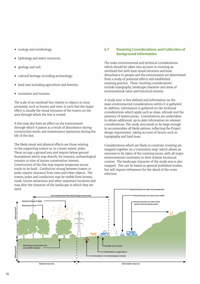
The scale of an overhead line relative to objects in close proximity, such as houses and trees, is such that the major effect is usually the visual intrusion of the towers on the area through which the line is routed.
A line may also have an effect on the environment through which it passes as a result of disturbance during construction works and maintenance operations during the life of the line.
The likely visual and physical effects are those relating to the supporting towers or, to a lesser extent, poles. These occupy a ground area and require below ground foundations which may disturb, for instance, archaeological remains or sites of nature conservation interest. Construction of the line may require temporary access tracks to be built. Conductors strung between towers or poles require clearance from trees and other objects. The towers/poles and conductors may be visible from houses, roads, tourist attractions and other important locations and may alter the character of the landscape in which they are sited.
6.7 Routeing Considerations and Collection of Background Information
The main environmental and technical considerations which should be taken into account in routeing an overhead line with least visual intrusion and least disturbance to people and the environment are determined from a study of potential effects and established routeing practice. These ‘routeing considerations’ include topography, landscape character and areas of environmental value and historical interest.
A ‘study area’ is first defined and information on the main environmental considerations within it is gathered. In addition, information is gathered on the technical considerations which apply such as slope, altitude and the presence of watercourses. Consultations are undertaken to obtain additional, up-to-date information on relevant considerations. The study area needs to be large enough to accommodate all likely options, reflecting the Project design requirement, taking account of factors such as topography and land mass.
Considerations which are likely to constrain routeing are mapped together on a ‘constraints map’ which allows an overview to be taken of the routeing issues, with all major environmental constraints in their relative locational context. The landscape character of the study area is also mapped. This can be based on general published studies, but will require refinement for the detail of the route selection.
Hazard to birds in flight
Removal of trees
Disturbance of ground cover and wildlife habitats
Natural resources
Belo
w g
rou
nd
Abo
ve g
rou
nd
Man made resources
Disturbance to agriculture
Possible access track
Disturbance to archaeological remains
Visual intrusion on views from properties
Area temporarily disturbed during construction Visual intrusion on views from roads
Visual intrusion on views from tourist and recreation areas
19
6.8 Routeing Strategy
A routeing strategy is developed, based on established practice for line routeing and a general understanding of the technical and environmental constraints and opportunities relating to routeing an overhead line through the identified study area.
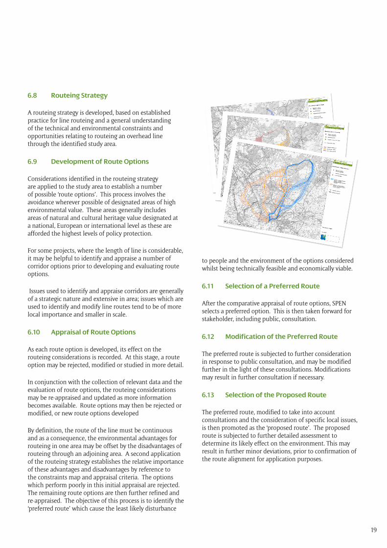
6.9 Development of Route Options
Considerations identified in the routeing strategy are applied to the study area to establish a number of possible ‘route options’. This process involves the avoidance wherever possible of designated areas of high environmental value. These areas generally includes areas of natural and cultural heritage value designated at a national, European or international level as these are afforded the highest levels of policy protection.
For some projects, where the length of line is considerable, it may be helpful to identify and appraise a number of corridor options prior to developing and evaluating route options.
Issues used to identify and appraise corridors are generally of a strategic nature and extensive in area; issues which are used to identify and modify line routes tend to be of more local importance and smaller in scale.
6.10 Appraisal of Route Options
As each route option is developed, its effect on the routeing considerations is recorded. At this stage, a route option may be rejected, modified or studied in more detail.
In conjunction with the collection of relevant data and the evaluation of route options, the routeing considerations may be re-appraised and updated as more information becomes available. Route options may then be rejected or modified, or new route options developed
By definition, the route of the line must be continuous and as a consequence, the environmental advantages for routeing in one area may be offset by the disadvantages of routeing through an adjoining area. A second application of the routeing strategy establishes the relative importance of these advantages and disadvantages by reference to the constraints map and appraisal criteria. The options which perform poorly in this initial appraisal are rejected. The remaining route options are then further refined and re-appraised. The objective of this process is to identify the ‘preferred route’ which cause the least likely disturbance
to people and the environment of the options considered whilst being technically feasible and economically viable.
6.11 Selection of a Preferred Route
After the comparative appraisal of route options, SPEN selects a preferred option. This is then taken forward for stakeholder, including public, consultation.
6.12 Modification of the Preferred Route
The preferred route is subjected to further consideration in response to public consultation, and may be modified further in the light of these consultations. Modifications may result in further consultation if necessary.
6.13 Selection of the Proposed Route
The preferred route, modified to take into account consultations and the consideration of specific local issues, is then promoted as the ‘proposed route’. The proposed route is subjected to further detailed assessment to determine its likely effect on the environment. This may result in further minor deviations, prior to confirmation of the route alignment for application purposes.
20
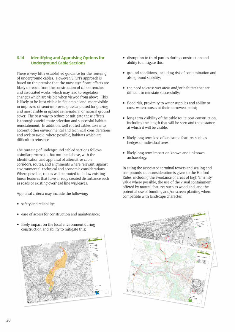
6.14 Identifying and Appraising Options for Underground Cable Sections
There is very little established guidance for the routeing of underground cables. However, SPEN’s approach is based on the premise that the most significant effects are likely to result from the construction of cable trenches and associated works, which may lead to vegetation changes which are visible when viewed from above. This is likely to be least visible in flat arable land, more visible in improved or semi-improved grassland used for grazing and most visible in upland semi-natural or natural ground cover. The best way to reduce or mitigate these effects is through careful route selection and successful habitat reinstatement. In addition, well routed cables take into account other environmental and technical considerations and seek to avoid, where possible, habitats which are difficult to reinstate.
The routeing of underground cabled sections follows a similar process to that outlined above, with the identification and appraisal of alternative cable corridors, routes, and alignments where relevant, against environmental, technical and economic considerations. Where possible, cables will be routed to follow existing linear features that have already created disturbance such as roads or existing overhead line wayleaves.
Appraisal criteria may include the following:
• safety and reliability;
• ease of access for construction and maintenance;
• likely impact on the local environment during construction and ability to mitigate this;
• disruption to third parties during construction and ability to mitigate this;
• ground conditions, including risk of contamination and also ground stability;
• the need to cross wet areas and/or habitats that are difficult to reinstate successfully;
• flood risk, proximity to water supplies and ability to cross watercourses at their narrowest point;
• long term visibility of the cable route post construction, including the length that will be seen and the distance at which it will be visible;
• likely long term loss of landscape features such as hedges or individual trees;
• likely long term impact on known and unknown archaeology.
In siting the associated terminal towers and sealing end compounds, due consideration is given to the Holford Rules, including the avoidance of areas of high ‘amenity’ value where possible, the use of the visual containment offered by natural features such as woodland, and the potential use of bunding and/or screen planting where compatible with landscape character.
21
7.1 Introduction
Environmental Impact Assessment (EIA) is a systematic process intended to identify, predict and assess likely environmental effects of proposed projects and to provide a level of environmental information within the resultant Environmental Statement (ES) to assist decision-makers in making an informed decision on an application. EIA should focus on likely ‘significant’ effects and the measures available to avoid, reduce or mitigate significant adverse effects. EIA is also an iterative process and is used to inform the more detailed review of the route alignment and, where relevant, substation positioning.
In addition to the environmental factors considered at the routeing stage, there are a number of additional factors considered at this stage given that they relate to the specific location of the infrastructure, including the potential for temporary effects associated with the construction process.
These additional factors include:
• air quality and emissions including dust;
• noise and vibration;
• waste management;
• water quality and resources;
• electric and magnetic fields.
The objective at this stage remains to avoid/reduce likely effects on people and on environmentally sensitive areas where possible. Minor refinements to the route alignment may be made in consultation with landowners, stakeholders and local communities if appropriate. At this stage, a review of likely adverse environmental effects is undertaken to determine whether or not there is any emerging trigger for the consideration of undergrounding any sections of the line. If this proves to be the case, the proposed route alignment will be reconsidered accordingly.
7.2 Overall Approach
SPEN’s overall approach is reviewed regularly to ensure compliance with regulatory requirements for EIA in Scotland, England and Wales. Further reviews are undertaken on a project by project basis, including a check against the list of information which is required to be
included in an ES.
Guidance on Assessment Methodologies
EIA Regulations do not specify the use of any particular methodology for the assessment process. However, there are a number of sources of good practice guidance available from consenting authorities and also from the Institute of Environmental Management and Assessment (IEMA) and other professional bodies. SPEN has, over the years, contributed to a number of these good practice guidance documents, which are not listed here as they are updated on a regular basis.
7.3 The Assessment and Reporting Process
Scoping the EIA
The first stage within the EIA process is to ‘scope’ the EIA, to focus the process on the key environmental issues and possible effects; to identify those which are unlikely to need detailed study; to ensure that up-to-date and relevant information is taken forward into the ES and to provide a means to discuss methods of impact assessment. This commonly involves the preparation of a Scoping Report which accompanies a ‘Request for a Scoping Opinion’ to the consenting authorities identified in Chapter 3, as to the information to be provided in the ES.
Collecting Baseline Information
The next stage in undertaking the assessment of the likely significant effects of the project is to establish the existing ‘baseline’ environmental conditions. This involves supplementing the information already obtained at the route selection stage with more detailed information for the proposed route alignment, including the likely gathering of more field survey information. It also involves further consultation with both statutory and non-statutory consultees.
Identifying and Assessing Effects
EIA regulations require a description of the likely significant effects of the development on the environment, which should cover direct and indirect effects and any secondary, cumulative, short, medium and long-term, permanent and temporary, positive and negative effects of the development, resulting from:
7 Environmental Impact Assessment of Major Electrical Infrastructure Projects (Stage 2)
22
(a) the existence of the development;
(b) the use of natural resources;
(c) the emission of pollutants, the creation of nuisances and the elimination of waste.
The interaction between effects should also be considered. For example, the effects of an overhead line on visual amenity and on cultural heritage may interact to produce an indirect effect on tourism within an area.
The likely significance of effects will depend on the characteristics of the effect (type/extent/magnitude) and the sensitivity of the ‘receptors’ affected by the proposed development. With some topics such as noise or air quality, it may be possible to use measurable, quantifiable, international or national guidelines or legislative criteria to identify the threshold at which an effect becomes significant. Central and local government and statutory bodies often have set standard thresholds of significance for a wide range of effects. Although not specifically set for EIA purposes, this information can be used, where appropriate, to determine significance thresholds. For other topics, the assessment of significance is more difficult, because the effect has to be measured using a combination of quantitative and qualitative criteria and an element of professional judgement is required.
Mitigation Measures
EIA regulations require a description of the measures envisaged “to prevent, reduce and where possible offset any significant adverse effects on the environment”. Whilst these measures are often referred to collectively as mitigation, SPEN interprets the term to encompass measures to ‘reduce’ and ‘offset’ effects, as the most effective means of ‘preventing’ significant adverse effects associated with major electrical infrastructure projects is by careful routeing. Where mitigation measures are proposed, their likely effectiveness must be examined, and the significance of the effect re-assessed and adjusted, as appropriate.
Measures to reduce effects are embodied in detailed adjustments to the route alignment, in the placement of individual towers; and possibly, in selected locations, and also at substation sites, the management of existing vegetative cover and new tree, shrub and hedgerow planting. Proposals for other mitigation measures such as off-site planting, woodland management, and actions which are proposed in commercial forestry depend on the co-operation of the relevant landowner.
Preparing the Environmental Statement
The ES should present the findings of the EIA in a comprehensive, clear and objective manner. In accordance with EIA Regulations, a Non-Technical Summary of the ES should also be prepared. This describes the EIA process and its findings in a manner that is easily understood by the general public.
The ES should provide an outline of the main alternatives studied by the applicant (i.e. route options) with an indication, taking into account environmental effects, of the main reasons for the alternative selected (i.e. the proposed route alignment). It is also SPEN’s policy that every ES should contain a chapter explaining how the methodology, assessment criteria, significance thresholds, and the document as a whole satisfy the requirements of the EIA Regulations. Each assessment chapter also details the assessment methodology used to assess the likely effect on the topic in question.
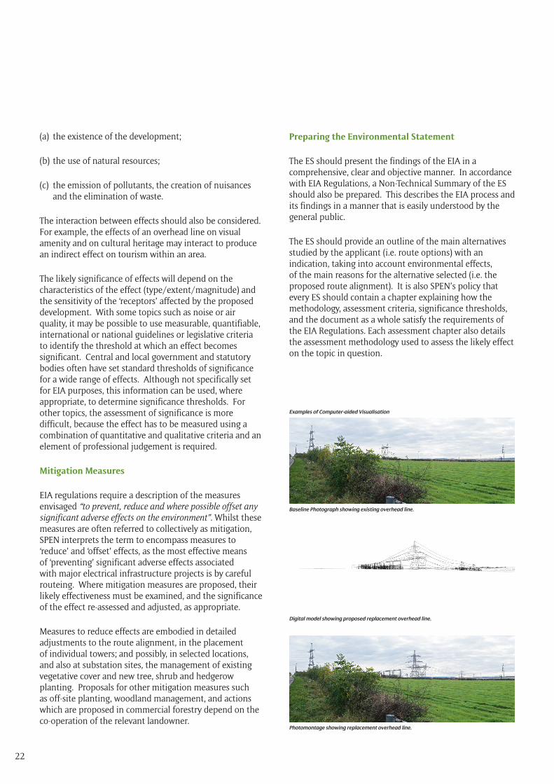
Baseline Photograph showing existing overhead line.
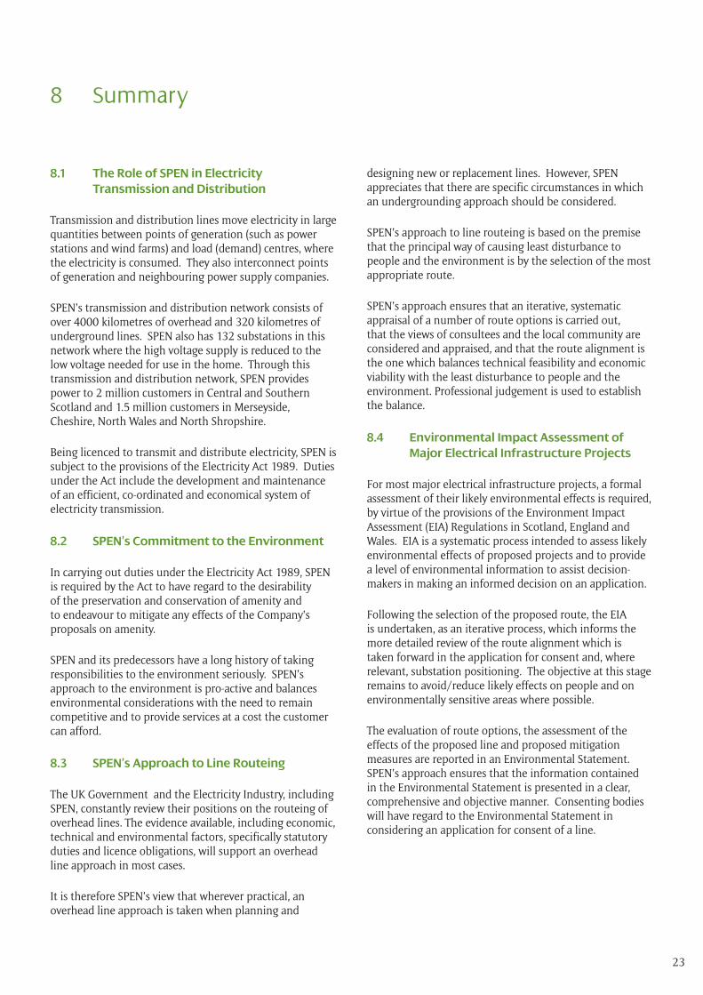
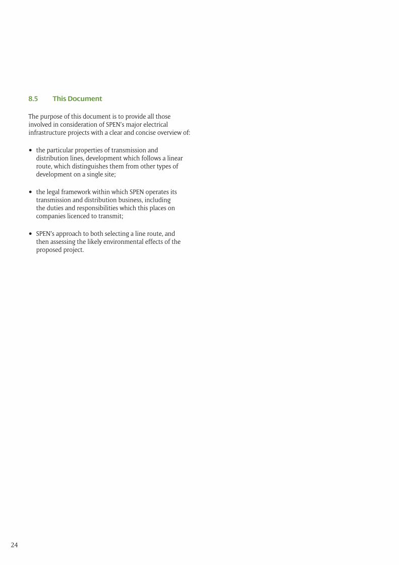
Examples of Computer-aided Visualisation
Digital model showing proposed replacement overhead line.
Photomontage showing replacement overhead line.
23
8.1 The Role of SPEN in Electricity Transmission and Distribution
Transmission and distribution lines move electricity in large quantities between points of generation (such as power stations and wind farms) and load (demand) centres, where the electricity is consumed. They also interconnect points of generation and neighbouring power supply companies.
SPEN’s transmission and distribution network consists of over 4000 kilometres of overhead and 320 kilometres of underground lines. SPEN also has 132 substations in this network where the high voltage supply is reduced to the low voltage needed for use in the home. Through this transmission and distribution network, SPEN provides power to 2 million customers in Central and Southern Scotland and 1.5 million customers in Merseyside, Cheshire, North Wales and North Shropshire.
Being licenced to transmit and distribute electricity, SPEN is subject to the provisions of the Electricity Act 1989. Duties under the Act include the development and maintenance of an efficient, co-ordinated and economical system of electricity transmission.
8.2 SPEN’s Commitment to the Environment
In carrying out duties under the Electricity Act 1989, SPEN is required by the Act to have regard to the desirability of the preservation and conservation of amenity and to endeavour to mitigate any effects of the Company’s proposals on amenity.
SPEN and its predecessors have a long history of taking responsibilities to the environment seriously. SPEN’s approach to the environment is pro-active and balances environmental considerations with the need to remain competitive and to provide services at a cost the customer can afford.
8.3 SPEN’s Approach to Line Routeing
The UK Government and the Electricity Industry, including SPEN, constantly review their positions on the routeing of overhead lines. The evidence available, including economic, technical and environmental factors, specifically statutory duties and licence obligations, will support an overhead line approach in most cases.
It is therefore SPEN’s view that wherever practical, an overhead line approach is taken when planning and
designing new or replacement lines. However, SPEN appreciates that there are specific circumstances in which an undergrounding approach should be considered.
SPEN’s approach to line routeing is based on the premise that the principal way of causing least disturbance to people and the environment is by the selection of the most appropriate route.
SPEN’s approach ensures that an iterative, systematic appraisal of a number of route options is carried out, that the views of consultees and the local community are considered and appraised, and that the route alignment is the one which balances technical feasibility and economic viability with the least disturbance to people and the environment. Professional judgement is used to establish the balance.
8.4 Environmental Impact Assessment of Major Electrical Infrastructure Projects
For most major electrical infrastructure projects, a formal assessment of their likely environmental effects is required, by virtue of the provisions of the Environment Impact Assessment (EIA) Regulations in Scotland, England and Wales. EIA is a systematic process intended to assess likely environmental effects of proposed projects and to provide a level of environmental information to assist decision-makers in making an informed decision on an application.
Following the selection of the proposed route, the EIA is undertaken, as an iterative process, which informs the more detailed review of the route alignment which is taken forward in the application for consent and, where relevant, substation positioning. The objective at this stage remains to avoid/reduce likely effects on people and on environmentally sensitive areas where possible.
The evaluation of route options, the assessment of the effects of the proposed line and proposed mitigation measures are reported in an Environmental Statement. SPEN’s approach ensures that the information contained in the Environmental Statement is presented in a clear, comprehensive and objective manner. Consenting bodies will have regard to the Environmental Statement in considering an application for consent of a line.
8 Summary
24
8.5 This Document
The purpose of this document is to provide all those involved in consideration of SPEN’s major electrical infrastructure projects with a clear and concise overview of:
• the particular properties of transmission and distribution lines, development which follows a linear route, which distinguishes them from other types of development on a single site;
• the legal framework within which SPEN operates its transmission and distribution business, including the duties and responsibilities which this places on companies licenced to transmit;
• SPEN’s approach to both selecting a line route, and then assessing the likely environmental effects of the proposed project.
25
Appendix 1 : The Holford Rules
The Holford Rules for the Routeing of New High Voltage Overhead Transmission Lines
It is generally accepted across the electricity industry that the guidelines developed by the late Lord Holford in 1959 for routeing overhead transmission lines, ‘The Holford Rules’, should continue to be employed as the basis for routeing high voltage overhead transmission lines. The Holford Rules were reviewed circa 1992 by the National Grid Company (NGC) Plc. (now National Grid Transmission (NGT)) as owner and operator of the electricity transmission network in England and Wales, with notes of clarification added to update the Rules.
A subsequent review of the Holford Rules (and NGC clarification notes) was undertaken by Scottish Hydro Electric Transmission Limited (SHETL) in 2003 to reflect Scottish circumstances. The principles of these guidelines for the routeing of new high voltage overhead transmission lines, with the NGC 1992 and SHETL 2003 notes have been considered within this Strategic Environmental Review. The Holford Rules are detailed below.
Rule 1
Avoid altogether, if possible, the major areas of highest amenity value, by so planning the general route of the line in the first place, even if the total mileage is somewhat increased in consequence.
Note on Rule 1
(a) Investigate the possibility of alternative routes, avoiding altogether, if possible major areas of highest amenity value. The consideration of alternative routes must be an integral feature of environmental statements. If there is an existing transmission line through a major area of highest amenity value and the surrounding land use has to some extent adjusted to its presence, particularly in the case of commercial forestry, then effect of remaining on this route must be considered in terms of the effect of a new route avoiding the area.
(b) Areas of highest amenity value require to be established on a project-by-project basis considering Schedule 9 to The Electricity Act 1989, Scottish Planning Policies, National Planning Policy Guidelines, Circulars and Planning Advice Notes and the spatial extent of areas identified.
Examples of areas of highest amenity value which should be considered are:
• Special Area of Conservation (NPPG 14)
• Special Protection Area (NPPG 14)
• Ramsar Site (NPPG 14)
• National Scenic Areas (NPPG 14)
• National Parks (NPPG 14)
• National Nature Reserves (NPPG 14)
• Protected Coastal Zone Designations (NPPG 13)
• Sites of Special Scientific Interest (SSSI) (NPPG 14)
• Schedule of Ancient Monuments (NPPG 5)
• Listed Buildings (NPPG 18)
• Conservation Areas (NPPG 18)
• World Heritage Sites (a non-statutory designation) (NPPG 18)
• Historic Gardens and Designed Landscapes (a non-statutory designation) (NPPG 18)
Rule 2
Avoid smaller areas of high amenity value, or scientific interest by deviation; provided that this can be done without using too many angle towers, i.e. the more massive structures which are used when lines change direction.
Note on Rule 2
(c) Small areas of highest amenity value not included in Rule 1 as a result of their spatialextent should be identified along with other areas of regional or local high amenity value identified from development plans.
(d) Impacts on the setting of historic buildings and other cultural heritage features should be minimised.
(e) If there is an existing transmission line through an area of high amenity value and the surrounding landuses
26
have to some extent adjusted to its presence, particularly in the case of commercial forestry, then the effect of remaining on this line must be considered in terms of the effect of a new route deviating around the area.
Rule 3
Other things being equal, choose the most direct line, with no sharp changes of direction and thus with few angle towers.
Note on Rule 3
(a) Where possible choose inconspicuous locations for angle towers, terminal towers and sealing end compounds.
(b) Too few angles on flat landscape can also lead to visual intrusion through very long straight lines of towers, particularly when seen nearly along the line.
Rule 4
Choose tree and hill backgrounds in preference to sky backgrounds, wherever possible; and when the line has to cross a ridge, secure this opaque background as long as possible and cross obliquely when a dip in the ridge provides an opportunity. Where it does not, cross directly, preferably between belts of trees.
Rule 5
Prefer moderately open valleys with woods where the apparent height of towers will be reduced, and views of the line will be broken by trees.
Notes on Rules 4 and 5
(a) Utilise background and foreground features to reduce the apparent height and domination of towers from main viewpoints.
(b) Minimise the exposure of numbers of towers on prominent ridges and skylines.
(c) Where possible follow open space and run alongside, not through woodland or commercial forestry, and consider opportunities for skirting edges of copses and woods. Where there is no reasonable alternative to cutting through woodland or commercial forestry, the Forestry Commission Guidelines should be followed
(Forest Landscape Design Guidelines, second edition, The Forestry Commission 1994 and Forest Design Planning – A Guide to Good Practice, Simon Bell/The Forest Authority 1998).
(d) Protect existing vegetation, including woodland and hedgerows, and safeguard visual and ecological links with the surrounding landscape.
Rule 6
In country which is flat and sparsely planted, keep the high voltage lines as far as possible independent of smaller lines, converging routes, distribution poles and other masts, wires and cables, so as to avoid a concatenation or ‘wirescape’.
Note on Rule 6
(a) In all locations minimise confusing appearance.
(b) Arrange wherever practicable that parallel or closely related routes are planned with tower types, spans and conductors forming a coherent appearance. Where routes need to diverge allow, where practicable, sufficient separation to limit the impacts on properties and features between lines.
Rule 7
Approach urban areas through industrial zones, where they exist; and when pleasant residential and recreational land intervenes between the approach line and the substation, go carefully into the comparative costs of undergrounding, for lines other than those of the highest voltage.
Note on Rule 7
(a) When a line needs to pass through a development area, route it so as to minimise as far as possible the effect on development.
(b) Alignments should be chosen after consideration of impacts on the amenity of existing development and on proposals for new development.
(c) When siting substations take account of the impacts of the terminal towers and line connections that will need to be made and take advantage of screening features such as ground form and vegetation.
27
Explanatory Note on Rule 7
The assumption made in Rule 7 is that the highest voltage line is overhead.
Supplementary Notes
(a) Residential Areas Avoid routeing close to residential areas as far as possible on grounds of general amenity.
(b) Designations of Regional and Local Importance Where possible choose routes which cause the least disturbance to Areas of Great Landscape Value and other similar designations of Regional or Local Importance.
(c) Alternative Lattice Steel Tower Designs
In addition to adopting appropriate routeing, evaluate where appropriate the use of alternative lattice steel tower designs available where these would be advantageous visually, and where the extra cost can be justified. [Note: SHETL have reviewed the visual and landscape arguments for the use of lattice steel towers in Scotland and summarised these in a document entitled Overhead Transmission Line Tower Study 2004].
Further Notes on Clarification to The Holford Rules
Line Routeing and People
The Holford Rules focused on landscape amenity issues for the most part. However, line routeing practice has given greater importance to people, residential areas etc.
The following notes are intended to reflect this.
(a) Avoid routeing close to residential areas as far as possible on grounds of general amenity.
(b) In rural areas avoid as far as possible dominating isolated house, farms or other small-scale settlements.
(c) Minimise the visual effect perceived by users of roads, and public rights of way, paying particular attention to the effects of recreational, tourist and other well used routes.
Supplementary Notes on the Siting of Substations
(a) Respect areas of high amenity value (see Rule 1) and take advantage of the containment of natural features such as woodland, fitting in with the landscape character of the area.
(b) Take advantage of ground form with the appropriate use of site layout and levels to avoid intrusion into surrounding areas.
(c) Use space effectively to limit the area required for development, minimizing the impacts on existing land use and rights of way.
(d) Alternative designs of substation may also be considered, e.g. ‘enclosed’, rather than ‘open’, where additional cost can be justified.
(e) Consider the relationship of tower and substation structures with background and foreground features, to reduce the prominence of structures from main viewpoints.
(f) When siting substations take account of the impacts of line connections that will need to be made.
28
APPENDIX A
INTERPRETATION OF THE HOLFORD RULES 1 AND 2 AND THE NOTES TO RULE 2 REGARDING THE SETTING OF A SCHEDULED ANCIENT MONUMENT OR A LISTED BUILDING
1 Interpretation of The Holford Rules 1 and 2
1.1 Introduction
Rules 1 refers to avoiding major areas of highest amenity value, Rule 2 refers to avoiding smaller areas of high amenity value. These rules therefore require identification of areas of amenity value in terms of highest and high, implying a hierarchy, and the extent of their size(s) or area(s) in terms of major and smaller areas.
The NGC Notes to these Rules identify at Rule 1(b) areas of highest amenity value and at Rule 2(a) and (b) of high amenity value that existed in England circa 1992.
1.2 Designations
Since 1949 a framework of statutory measures has been developed to safeguard areas of high landscape value and nature conservation interest. In addition to national designations, European Community Directives on nature conservation, most notably through Special Areas of Conservation under the Habitats and Species Directive (92/43/EC) and Special Protection Areas under the Conservation of Wild Birds Directive (79/409/EEC) have been implemented. Governments have also designated a number of Ramsar sites under the Ramsar Convention on wetlands of International Importance (CM6464). Scottish Office circulars 13/1991 and 6/1995 are relevant sources of information and guidance. In addition, a wide range of non-statutory landscape and nature conservation designations affect Scotland.
1.3 Amenity
The term ‘Amenity’ is not defined in The Holford Rules but has generally been interpreted as designated areas of scenic, landscape, nature conservation, scientific, architectural or historical interest.
This interpretation is supported by paragraph 3 of the Schedule 9 to the electricity Act 1989 (The Act). Paragraph 3 (1)(a) requires that in formulating any relevant proposals the licence holder must have regard to the desirability of preserving natural beauty, or conserving flora, fauna and
geological or physiological features of special interest and of protecting sites, buildings, including structures and objects of architectural, historic or archaeological interest. Paragraph 3 (1)(b) requires the license holder to do what he reasonably can do to mitigate any effect which the proposals would have on the natural beauty of the countryside or on any flora, fauna, features, sites, buildings or objects.
1.4 Hierarchy of Amenity Value
Rules 1 and 2 imply a hierarchy of amenity value from highest to high.
Schedule 9 to the Act gives no indication of hierarchy of value and there is no suggestion of a hierarchy of value in either NPPG5: Archaeology and Planning, NPPG 13: Coastal Planning, NPPG 14: Natural Heritage or NPPG 18: Planning and the Historic Environment. Nevertheless, designations give an indication of the level of importance of the interest to be safeguarded.
1.5 Major and Smaller Areas
Rules 1 and 2 imply consideration of the spatial extent of the area of amenity in the application of Rules 1 and 2.
1.6 Conclusion
Given that both the spatial extent in terms of major and smaller and the amenity value in terms of highest and high that must be considered in applying Rules 1 and 2, that no value in these terms is provided by either Schedule 9 to the Act, relevant Scottish Planning Policies or National Planning policy Guidelines, then these must be established on a project-by-project basis. Designations can be useful in giving an indication of the level of importance and thus value of the interest safeguarded. The note to The Holford Rules can thus only give examples of the designations which may be considered to be of the highest amenity value.
2. The setting of a Scheduled Ancient Monument or a Listed Building
The NGC note to Rule 2 refers to the setting of historic buildings and other cultural heritage features. NPPG 5: Archaeology and Planning refers to the setting of scheduled ancient monuments and NPPG 18: Planning and the Historic Environment refers to the setting Listed Buildings. None of these documents define setting.
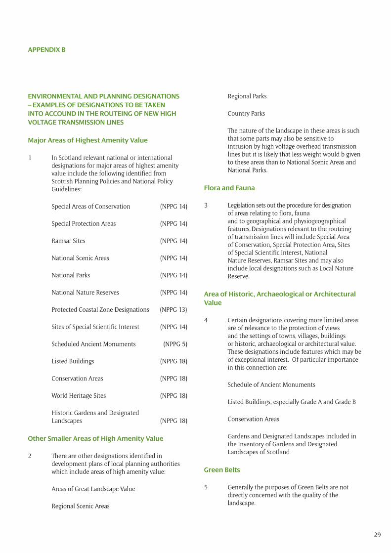
29
ENVIRONMENTAL AND PLANNING DESIGNATIONS – EXAMPLES OF DESIGNATIONS TO BE TAKEN INTO ACCOUND IN THE ROUTEING OF NEW HIGH VOLTAGE TRANSMISSION LINES
Major Areas of Highest Amenity Value
1 In Scotland relevant national or international designations for major areas of highest amenity value include the following identified from Scottish Planning Policies and National Policy Guidelines:
Special Areas of Conservation (NPPG 14)
Special Protection Areas (NPPG 14)
Ramsar Sites (NPPG 14)
National Scenic Areas (NPPG 14)
National Parks (NPPG 14)
National Nature Reserves (NPPG 14)
Protected Coastal Zone Designations (NPPG 13)
Sites of Special Scientific Interest (NPPG 14)
Scheduled Ancient Monuments (NPPG 5)
Listed Buildings (NPPG 18)
Conservation Areas (NPPG 18)
World Heritage Sites (NPPG 18)
Historic Gardens and Designated Landscapes (NPPG 18)
Other Smaller Areas of High Amenity Value
2 There are other designations identified in development plans of local planning authorities which include areas of high amenity value:
Areas of Great Landscape Value
Regional Scenic Areas
APPENDIX B
Regional Parks
Country Parks
The nature of the landscape in these areas is such that some parts may also be sensitive to intrusion by high voltage overhead transmission lines but it is likely that less weight would b given to these areas than to National Scenic Areas and National Parks.
Flora and Fauna
3 Legislation sets out the procedure for designation of areas relating to flora, fauna and to geographical and physiogeographical features. Designations relevant to the routeing of transmission lines will include Special Area of Conservation, Special Protection Area, Sites of Special Scientific Interest, National Nature Reserves, Ramsar Sites and may also include local designations such as Local Nature Reserve.
Area of Historic, Archaeological or Architectural Value
4 Certain designations covering more limited areas are of relevance to the protection of views and the settings of towns, villages, buildings or historic, archaeological or architectural value. These designations include features which may be of exceptional interest. Of particular importance in this connection are:
Schedule of Ancient Monuments
Listed Buildings, especially Grade A and Grade B
Conservation Areas
Gardens and Designated Landscapes included in the Inventory of Gardens and Designated Landscapes of Scotland
Green Belts
5 Generally the purposes of Green Belts are not directly concerned with the quality of the landscape.
30
Appendix 2 : Glossary of Terms
Angle or Tension Pole/Tower: a tower or pole erected to allow for a change in direction of the line.
Conductor: a metallic wire strung from tower to tower or pole to pole, to carry electric current.
Circuit: a combination of conductors (commonly three conductors) along which electricity is transmitted or distributed.
Earth Wire: a wire erected above the topmost conductor at the tower peak or under slung on a wood pole. These are used for protection against lightning strikes but can also contain fibre optic cores for communication purposes.
Environmental Impact Assessment (EIA): a formal process used to identify, predict and assess the likely environmental effects of a proposed development.
Environmental Statement (ES): the document which reports the findings of an EIA.
Holford Rules: accepted guidance for routeing overhead lines in the UK.
Insulators: articulated strings made of either glass or polymeric compound. These are required to prevent electric current crossing to a tower or pole body.
Kilovolt (kV): One thousand (1000) volts.
Major Electrical Infrastructure Project: a development of overhead lines, underground cables and substations at 132kV and above.
Nationally Significant Infrastructure Project (NSIP): a major infrastructure development in England and Wales, defined in The Planning Act, 2008.
Overhead Line: an electric line installed above ground, usually supported by lattice steel towers or wooden poles.
Preferred Route: a route taken forward to stakeholder consultation following a comparative review of route options.
Proposed Route: a route taken forward to the EIA stage following stakeholder consultation.
Route Alignment: the alignment of the route which forms the basis of the application for consent.
Route Options: a number of routes between the start and end connection points, may be several hundred metres wide.
Span: the section of overhead line between two towers or two wood poles.
SP Energy Networks (SPEN): part of the ScottishPower Group of companies. SPEN transmits and distributes electricity to around 3.5 million customers in the South of Scotland, Cheshire, Merseyside, North Shropshire and North Wales.
Study Area: the area within which the routeing study takes place.
Substation: controls the flow and voltage of electricity by means of transformers and switchgear, with facilities for control, fault protection and communications.
Terminal Pole/Tower: a tower or pole required where the line terminates either at a substation or at the end of an underground cable.
The National Grid: the electricity transmission network in the UK.
Transformers: Substation components used to increase or decrease the voltage of electricity.
Volts: the international system unit of electric potential and electromotive force.