Maintenance manual no. MM-0556 Trailer Air Suspension...
52
Trailer Air Suspension System MERITOR EUROFLEX 9i Range Issue 02/2002 Maintenance manual no. MM-0556 Issue: October 2009 TM
Transcript of Maintenance manual no. MM-0556 Trailer Air Suspension...

Trailer Air Suspension SystemMERITOR EUROFLEX 9i Range
Issue 02/2002
Maintenance manual no. MM-0556
Issue: October 2009
TM

MERITOR EUROFLEXTM 9iSuspension Range 2
pg. 4 Section 1 - General Informationpg. 5 Safety Instructionspg. 6 Warranty
pg. 8 Section 2 - Introductionpg. 9 Descriptionpg. 9 Principle of Operationpg. 10 Ancilliary Equipmentpg. 11 Important Suspension Parameterspg. 12 Exploded view & Parts Listpg. 13 ID Plate
pg. 14 Section 3 - Inspection & Maintenance Procedures
pg. 15 Before entering Servicepg. 15 Inspectionpg. 16 Maintenancepg. 16 Lubricationpg. 17 Ride Height Adjustment
pg. 20 Section 4 - Suspension Overhaulpg. 21 Air Spring Removalpg. 22 Fitting New Air Springpg. 24 Shock Absorber Replacementpg. 27 Pivot Bush Removalpg. 31 Pivot Bush Replacement
pg. 34 Section 5 - Axle Removal & Replacementpg. 35 Axle Removalpg. 36 Axle Replacement
pg. 38 Section 6 - Axle Alignment (Tracking)pg. 39 Before you Align Axlepg. 39 Front Axlepg. 39 Rear Axle
pg. 42 Section 7 - Axle & Suspension Welding Recommendations
pg. 43 Axle & Suspension Welding Recommendations
pg. 44 Section 8 - Maintenance Schedulespg. 45 Maintenance Schedulespg. 46 Table of Torque Values
pg. 48 Section 9 - Fault Finding & Diagnosticspg. 49 Braking Problemspg. 49 Tyre Wearpg. 49 Excessive Rollpg. 49 Suspension Related Problemspg. 50 Axle Lift Problemspg. 50 Fault Diagnostic Table
Contents

MERITOR EUROFLEXTM 9i Suspension Range3
All rights reserved.No part of this publication may be reproduced in any form orby any means or granted to any third parties without thewritten permission of ARVINMERITOR.ARVINMERITOR reserves the right to publish revisions at any time for technical or commercial purposes. Therefore all material contained in this manual isbased on the latest information available at time of publicationapproval.
© 2009 ArvinMeritor, Inc.Document No. MM-0556Edition: October 2009

MERITOR EUROFLEXTM 9i Suspension Range 4
General Information
pg. 5 Safety Instructionspg. 6 Warranty
1

1 General Information
This manual describes the correct lubrication, service andinstallation procedures for the MERITOR EUROFLEXTM 9i trailer airsuspension system. Information contained in this publication wasin effect at the time the publication was approved for printing andis subject to change without notice or liability.
The designated trademarks are registered marks of theirrespective owners and ArvinMeritor and its affiliates are notcommercially connected, affiliated, or associated with any of theowners of such marks. The ArvinMeritor products presented hereinare not endorsed or authorized by any of the trademark owners.
You must follow company procedures and understand allprocedures and instructions before you begin to service or repair aunit. Some procedures require the use of special tools andlubricants for safe and correct service. Failure to use special toolswhen required can cause series personal injury to servicepersonnel, as well as damage to equipment and components.
ARVINMERITOR uses the following notations to warn the user ofpossible safety issues and to provide information that will preventdamage to equipment and components.
WARNING
A Warning indicates you must follow a procedure exactly.Otherwise serious Personal injury can occur.
NOTE:
A NOTE indicates an operation, procedure or instruction thatis important for correct service. A NOTE can also supplyInformation that can help to make service quicker and easier.
CAUTION
A caution indicates that you must follow a procedure exactly.Otherwise, damage to equipment or components can occur.Serious personal injury can also result, in addition todamaged or malfunctioning equipment or components.
This symbol indicates that a you must tightenfasteners to a specific torque value.
MERITOR EUROFLEXTM 9i Suspension Range5
Safety Instructions
• Observe the manufacturers safety instructions for jacking upand securing the vehicle
• Only use original ArvinMeritor parts
• Use only the tools recommended
• Observe the following service instructions and notes
• When working on the suspension assembly you must ensurethat it cannot be activated inadvertently
• Never use compressed air to remove dust or for the purpose ofdrying. Any type of dust can be injurous to health if inhaled.
• When the servicing has been completed, it is essential that youroad test the vehicle.
Access Information on ArvinMeritor's WebSiteAdditional maintenance and service information for ArvinMeritor'scommercial vehicle systems component lineup is also available atwww.meritorhvs.com
To access information go to Products & Services Icon; from dropdown menu click on Literature on Demand. The screen will displayan index of publications by type.

MERITOR EUROFLEXTM 9i Suspension Range 6
Patents and applications of MERITOR HEAVYVEHICLE SYSTEMS Ltd that is specifically relevantto air suspension systems:
GB Patent No: GB2367111EU Patent No: EP1315918US Patent No: US7252298
GB Patent No: GB2396140GB Patent No: GB2257670US Patent No: US7360774
Patents applied for:
EPO: EP030780387EP050257631EP060252792EP050254903
USA: US10/538816US11/446,455US10/916127US11/875139
China: CN20038106029CN061083548
Poland: PL20030376676
PARTS SHOWN ARE MADE FROM DRAWINGS IN WHICHCOPYRIGHT SUBSISTS. THE MAKING OF COPIES OF ANY OFTHESE PARTS IS PROHIBITED.
ROR, MERITOR, ARVINMERITOR AND INDAIR ARE ALL REGISTEREDTRADE MARKS IN THE UK AND ELSEWHERE
The high quality assurance management systems applied byARVINMERITOR are endorsed with the awarding of ISO 9001,Lloyd's Register Quality Assurance.
© 2009 ArvinMeritor, Inc.
1 General Information
ARVINMERITOR Suspension Warranty
MERITOR EUROFLEXTM 9i Air Suspension supplied in kits coveredfor 24 MONTHS PARTS AND LABOUR
MERITOR EUROFLEXTM 9i Air Suspension units assembled with anAxle by ArvinMeritor 36 MONTHS PARTS AND LABOUR. (MERITOREUROFLEXTM 9i Front and Rear Arms welded by ArvinMeritor arecovered for a further 2 years PARTS ONLY)
For full warranty terms and conditions see 'ARVINMERITORWarranty Terms and Conditions
Unless otherwise stated, Aftermarket components are warrantedfor 1 year, parts only, mechanical failure only.
Warranty Procedure
Should any ARVINMERITOR equipment fitted to your trailer becomeunserviceable within the warranty period, contact the trailermanufacturer or ARVINMERITOR Service Department who willadvise on the appropriate action.
A comprehensive network of original parts distributors and servicestations operate throughout Europe; this is supportedinternationally with agents strategically placed around the world.
ARVINMERITOR H.V.S. reserves the right to make changes inspecifications shown herein or add improvements at any timewithout notice or obligation.

MERITOR EUROFLEXTM 9i Suspension Range7

MERITOR EUROFLEXTM 9i Suspension Range 8
Introduction
pg. 9 Descriptionpg. 9 Principle of Operationpg. 10 Ancilliary Equipmentpg. 11 Important Suspension Parameterspg. 12 Exploded view & Parts Listpg. 13 ID Plate2

MERITOR EUROFLEXTM 9i Suspension Range9
Principle of Operation
During normal running in a straight line, striking bumps, potholesetc., superb ride characteristics are obtained due to the airspringsproviding a very low vertical suspension stiffness at the wheel.This ensures very little shock is transmitted to thechassis/payload, thus minimising structural damage or problemswith goods.
During cornering manoeuvres, the axle tube acts as an anti-rollbar and links each trailing arm. The majority of the compliance inroll comes from the multi-functional pivot bush.
Careful design of the damper characteristics and positioningensures a high degree of damping required to gain the bestpossible performance from an air suspension.
Modern dynamic analysis methods and testing were used todetermine such characteristics and positions.
Product Compatibilities
The MERITOR EUROFLEXTM 9i Suspension is compatible with thefollowing brake sizes:
Disc BrakesELSA 195 (K)D ELSA 2 (E)ELSA 225L (J)D ELSA 2 (E) - 120 OFFSETELSA 225L (J) - 120 OFFSET
Drum BrakesZMXQMXQ+BMXACMX
For further information visit www.RORCare.com
Description
The MERITOR EUROFLEXTM 9i range of air suspension system isbased on a semi-trailing arm suspension arrangement. The trailingarms are mounted onto the axle parallel to one another andperpendicular to the axle. The front of the trailing arm consists ofa pivot bushing, hanger bracket and alignment bosses, while therear of the trailing arm supports the air spring. (Figs 2.2 and 2.3)
The axle is attached to the trailing arms via a welding process thatcan only be performed by ARVINMERITOR. The trailing armscontain a multi-functional pivot bush at the eye ends, speciallydesigned to accommodate vertical inputs, but remaining stiff forthe fore and aft inputs. The trailing arms are mounted to hangerbrackets, which are then welded to the chassis.
Ride height is a very important measurement for overall vehicleheight. The ride height of the suspension unit is determined fromthe centerline of the axle to the under side of the vehicle chassis.(Fig 2.1).
Note: Ensure that ride height is set correctly. If ride height isincorrect this may result in damage to suspension componentsand affect the trailers performance. Refer to the TrailerManufacturers recommendations for ride height setting on tractorfifth wheel.
Features
Shock absorber with integral check strap
9 & 11 Tonne capacity designed for trailers and semi trailers.
Multi-functional bushing with interleaf shims for improved fore/aftstiffness.
Small diameter air spring for improved packaging.
Nominal ride height of 200 - 500mm with 200mm of total travel(100mm jounce and 100mm rebound nominal)
2 Introduction

MERITOR EUROFLEXTM 9i Suspension Range 10
5. ANTI-VACUUM SYSTEM
Ferry companies require that air suspended trailers are fullyexhausted before trailers are loaded aboard ship.Consequently there is risk that during loading, the rubber sidewalls of the airspring can become trapped between the internalrubber bump stop and piston and become damaged. Applicationsthat involve a rapid removal of the load (e.g. HuckePak), could alsocause the airspring sidewalls to become contracted and result indamage.These instances can be avoided by using an anti-vacuum system..
6. CHECK STRAPS & QUICK EXHAUST VALVES
All applications that involve a sudden removal of load (e.g. HukePak)must have a check strap on each axle or quick exhaust valves fitted.
CAUTION: Failure to adhere to this may result inserious damage to the suspension and may invalidate theArvinMeritor warranty.
2 Introduction
Ancillary Equipment
1. AXLE LIFT FACILITY
A choice of axle lift facilities are available to fit the MERITOREUROFLEXTM 9i suspension, all of which are capable of beingretrofitted.
2. AIRSPRING DUMP FACILITY
ARVINMERITOR recommends that all air suspended trailerswithout raise/lower valves are fitted with this facility.
When an air suspended trailer deflates, it can roll forward causingbending and possible collapse of the landing legs. This is causedby wheel rotation as the axle travels up. A good solution to thisproblem is to fit rocking type landing legs.
3. RAISE/LOWER FEATURE
If a raise/lower feature is installed on the trailer, the vehicle mustnot be driven off with the suspension in the raised or loweredposition. A height limitation valve must me fitted with this feature.
NOTE: Serious damage can occur to the suspension if the traileris driven in the raised/lowered position and doing so may void theArvinMeritor warranty.
4. AUTO DROP
ARVINMERITOR recommends the fitment of this system to removepotential damage to the tyres and running gear, from drivers notresetting the manual system before moving.

2 Introduction
Important Suspension Parameters
A. RIDE HEIGHT
This is the distance from the centre of the axle to the undersideof the chassis.
B. FRAME BRACKET HEIGHT
C. AIRSPRING PEDESTAL HEIGHT
D. PIVOT TO AXLE CENTRE LINE
This is the distance from the pivot centre in the frame bracketto the centre of the axle tube.*
E. AXLE CENTRE TO AIRSPRING CENTRE LINE
This is the distance from the axle tube centre to the centre ofthe airspring pedestal.*
* Both dimension 'D' and 'E' must be measured when the axleis in the ride height position and dimension 'A' is set.
MERITOR EUROFLEXTM 9i Suspension Range11
F. AXLE CENTRE LINE TO PIVOT BUSH CENTRE HEIGHT.
NOTE: Refer to ARVINMERITOR installation drawings CD or contactARVINMERITOR Technical Sales Department for allowable optionsand recommendations.
Fig 2.1

Exploded View - MERITOR EUROFLEXTM 9i Suspension Assembly
MERITOR EUROFLEXTM 9i Suspension Range 12
1 AXLE ASSEMBLY
2 PIVOT BUSHING
3 PIVOT BOLT
4 ECCENTRIC ALIGNMENT BOSS
5 WEAR WASHER
6 PIVOT BUSH SLEEVE
7 CONCENTRIC ALIGNMENT BOSS
8 WASHER - M24
9 HEX NUT - M24
10 HANGER BRACKET
11 SHOCK ABSORBER
12 SHOCK ABSORBER BOLT - UPPER
13 WASHER - M24
14 HEX NUT - M24
15 SHOCK ABSORBER BOLT - LOWER
16 AIR SPRING PEDESTAL
17 HEX NUT - M12
18 AIR SPRING
19 RETAINING SCREW M12 - AIR SPRING
20 WASHER - M12
2 Introduction
Fig 2.2
1
2
4
10
18
11
16
12
57
3
6
5
13
13
15
8
14
9
14
20
19
17

2 Introduction
MERITOR EUROFLEXTM 9i Suspension Range13
Identification Plate Details
The suspension type can be determined by viewing the details in thetype box “A” as shown (Fig 2.3)
Fig 2.3
A

MERITOR EUROFLEXTM 9i Suspension Range 14
Inspection & Maintenance
pg. 15 Before entering Servicepg. 15 Inspectionpg. 16 Maintenancepg. 16 Lubricationpg. 17 Ride Height Adjustment3

3 Inspection & Maintenance
MERITOR EUROFLEXTM 9i Suspension Range15
Inspection
WARNING
Check fastener torque values, tighten loose fasteners andreplace damaged or missing fasteners. Loose, damaged ormissing fasteners can cause loss of vehicle control, death,serious personal injury and damage to components.
Inspect air suspension components, height control valve and axleat regular intervals during normal operation and each time thetrailer is serviced.
Before each trip: Visually inspect the suspension system and listenfor any leaks.
Perform the following inspections after the first 1600 km(1000 miles) of operation and at normal service intervals orannually thereafter as a minimum.
1. Check fastener torque values, tighten loose fasteners and replace damaged or missing fasteners.
2. Inspect all upper and lower air spring and damper nuts and bolts for looseness and movement. Tighten any loose nuts and bolts to the correct torque value as specified in Section 8. Thereafter, inspect the suspension components each time the trailer is servicedor as specified above.
3. Inspect all height control valve nuts, bolts and linkage for looseness and movement. Tighten any loose nuts and bolts to the correct torque value as specified in Section 8. Thereafter, inspect the suspension components each time the trailer is serviced or as specified above
4. Inspect Pivot bolts for looseness and movement.Align/Track the axle before tightening any loose nuts and bolts to the correct torque value as specified in Section 8. Thereafter, inspect the suspension components each time the trailer is serviced or as specified above.
CAUTION
If any welding is done around the suspension and axle runninggear, then suitable precautions should be made to protect therunning gear from weld spatter. Failure to do so may result inpremature failure of running gear components.
Ensure that welding earth clamps or connectors are not connectedto any part of the suspension and axle running gear.
WARNING
To prevent serious eye injury, always wear safe Eyeprotection when you perform vehicle maintenance or service.
Before Entering Service
IF THE OPERATOR IS IN ANY DOUBT ABOUT THE SAFETY OFTHE VEHICLE, THEN IT SHOULD NOT BE OPERATED ANDQUALIFIED ADVICE SHOULD BE SOUGHT.
Check the suspension and brake systems operate correctly.
Check the suspension air system for leaks by charging the systemwith air and testing all joints and fittings using soapy water.
Ensure the suspension ride height is correctly set, by referring tothe Ride Height Adjustment details in Section 2.
If an axle lift system is fitted, operate the lift system to check itoperates correctly and observe the extra lift cylinders attached tothe levelling valve arms to ensure they function.
Carry out a visual inspection of all suspension and brake systempipe work to ensure no possibility of fouling or rubbing againsteach other or other components.
Check the brake system operates correctly.
Check the operation of all optional equipment fitted. If any doubtor problems arise refer to the appropriate service manual or seekqualified advice.

MERITOR EUROFLEXTM 9i Suspension Range 16
7. Inspect shock absorbers for worn bushings, oil leaks and dents. Check that the mounting holes have not become enlarged.
8. Inspect the structure of the suspension including:
Hanger Brackets
Trailing arm
Shock absorber mountings
Axle welds
Brake interference (cam or chamber)
Hanger bracket bracing (where fitted)
Alignment Bosses
Fasteners
WARNING: Verify that people are clear of the trailerbefore you inflate or deflate the air springs. The air
suspension has various pinch points that can cause seriouspersonal injury.
CAUTION: Do not add lubrication or cleaningsolvents to the air system. These additives can
contaminate the air system and damage fittings. Damage tocomponents will result.
9. Inspect the height control valve for air leaks and crackedlever arm housing. If air leaks or cracks are detected,replace the height control valve.
Lubrication
The MERITOR EUROFLEXTM 9i range of suspensions does notrequire lubrication, only lubrication is required when installingreplacement pivot bushes.
NOTE: Only use lubricant supplied in the service kit when fittingnew pivot bushes.
3 Inspection & Maintenance
WARNING: Check fastener torque values, tightenloose fasteners and replace damaged fasteners.
Loose, damaged or missing fasteners can cause loss ofVehicle control, serious personal injury and Damage tocomponents.
1. Inspect for, broken or missing fasteners. Repair or replace as needed. Refer to Section 8 for correct Torque specifications.
2. Inspect welds for cracks at the axle, hanger bracket andsuspension trailing arm.
3. Inspect bushings for free play, use a crow bar to check for looseness or free play. Replace bushings if there are any signs of excessive vertical movement.
CAUTION: Take care not to damage any of thesuspension components.
4. Inspect the rubber bellows of the air spring for any cuts or abrasions. Replace the air spring immediately if it is cut or damaged in anyway.
CAUTION: The Air Spring surface must be free ofinterference or obstructions by items such as tyres,
loose steel and brake chambers etc… Damage tocomponents can result from abrasion.
5. Check for obstructions or interference to the air spring surface that can lead to damage to the air spring.Relocate and secure items, such as air hoses, that can contact the air spring.
6. Check for leaks in the air lines, at the air spring bead plate, piston and mounting studs. Replace air lines,fittings or air springs that leak. Refer to Section 4 for replacement details.

MERITOR EUROFLEXTM 9i Suspension Range17
8. The ride height must be set on the axle that has the levelling valve.
9. If the trailer is fitted with a lift axle this should be in the down position.
Once an initial setting of the ride height has been made it shouldbe checked by measuring from the top of the axle tube to theunderside of the trailer frame, and comparing with the nominalride height less 63.5mm (tube radius) (Figs 3.1 & 3.2).
The nominal ride height is specified by the trailer builder and isshown on the axle or chassis identification plates.
If the ride height is found to require resetting the followingprocedure should be used :-
Lengthen or shorten the linkage rods which connect the levellingvalve arm to the axle (giving a proportional increase or decrease inthe ride height) by slackening the two screws that pinch therubber eye ends onto the drop bar and pulling the bar in or out ofthe rubber. If there is insufficient adjustment i.e. the bar is indanger of coming out of the rubber, then further adjustment canbe gained by slackening the bolts holding the levelling valve to thebracket and repositioning the valve within the holes. Bending ofthe levelling valve actuating arm is not recommended.
If the ride height is found to be above the recommended setting,the height should first be dropped below the required setting andthen increased back to the nominal ride height, thus avoiding the"dead band" in the actuating stroke of the valve. This can be doneby shortening the linkage rod and bleeding air from thesuspension by slackening the air pressure connection on top ofthe airsprings. This method also applies to situations where theride has accidentally been taken above the recommended setting.
NOTE: Some care is needed when checking the ride height as afalse reading may be obtained after tipping a load etc. Thelevelling valve emits and exhausts air very slowly, so time shouldbe allowed for it to react once adjusted.
3 Inspection & Maintenance
Ride Height Adjustment
WARNING: Overall trailer height must not exceedrecommended limits for territories of application for
the vehicle to clear bridge underpasses during operation.Serious personal injury and damage to components willresult.
This is an area that is probably most unfamiliar to the traileroperator and the one that will cause most problems if thefollowing parameters are not adhered to.
Too high a ride height can cause more roll motion too low meansthat there will be loss of axle travel (contacting bump stop) duringarduous use.
Parameters for setting ride height:
1. The trailer should be on level ground.
2. It should preferably be connected to the tractor unit to be used and in a straight line with the unit, or set at the correct kingpin height. Refer to chassis identification plate or contact manufacturer.
3. All the trailer brakes should be off.
4. There should be an air supply of at least 6.5 bar.
5. The trailer should be unladen .
6. If the trailer has been running it should be given at least10 minutes to "settle down".
7. The valve should be set on increasing height as there is a "dead band" in the actuating stroke of the valve.
MERITOR EUROFLEXTM 9i Suspension Range 18
3 Inspection & Maintenance
The valve emits air slightly faster than it exhausts. This is so thatlarge volumes of air are not constantly bled off during normalsuspension travel but still allowing a relatively quick reaction to anincrease in load or when the trailer is being brought up tooperating height from flat.
Determining the correct ride height
Measure ride height from the top of the axle to the bottom of thechassis rail. See diagram (Fig 3.1) and chart (Fig 3.2) for settingdimensions. This can be found on the axle I.D. plate or contactARVINMERITORs Technical Sales Department.
Fig 3.1
Fig 3.2
VehicleChassis
RideHeight
Dim“X”Dim
“Y”
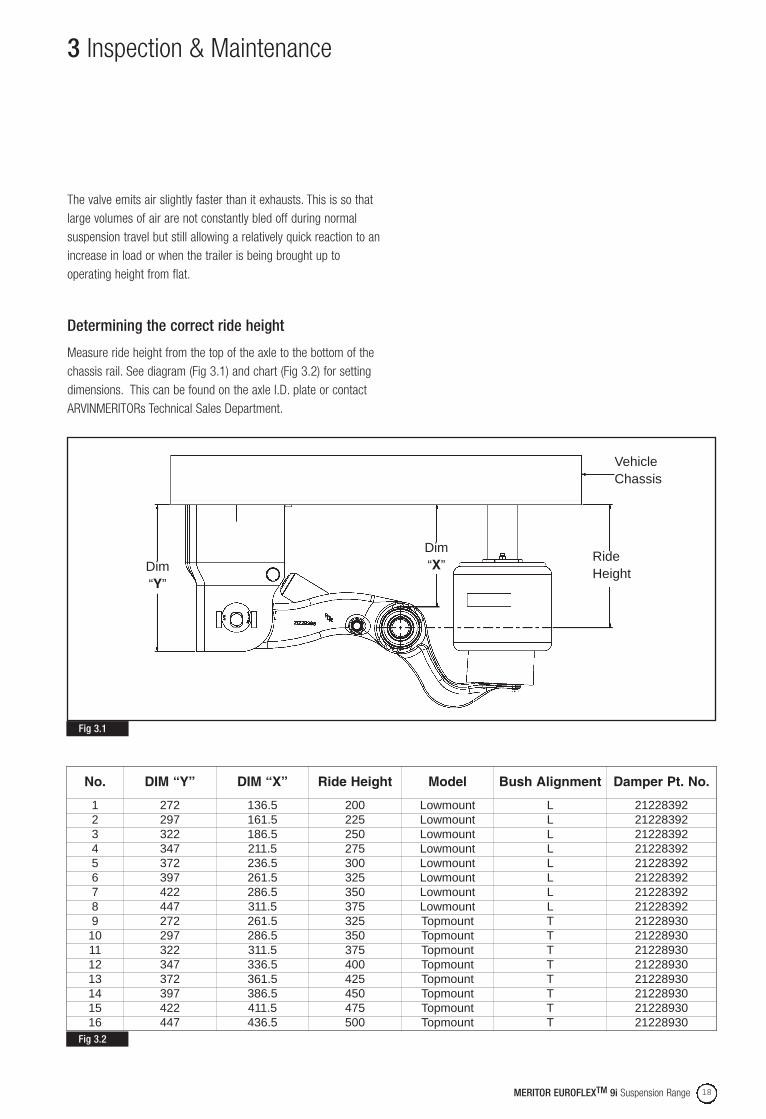
No. DIM “Y” DIM “X” Ride Height Model Bush Alignment Damper Pt. No.
1 272 136.5 200 Lowmount L 212283922 297 161.5 225 Lowmount L 212283923 322 186.5 250 Lowmount L 212283924 347 211.5 275 Lowmount L 212283925 372 236.5 300 Lowmount L 212283926 397 261.5 325 Lowmount L 212283927 422 286.5 350 Lowmount L 212283928 447 311.5 375 Lowmount L 212283929 272 261.5 325 Topmount T 21228930
10 297 286.5 350 Topmount T 2122893011 322 311.5 375 Topmount T 2122893012 347 336.5 400 Topmount T 2122893013 372 361.5 425 Topmount T 2122893014 397 386.5 450 Topmount T 2122893015 422 411.5 475 Topmount T 2122893016 447 436.5 500 Topmount T 21228930

MERITOR EUROFLEXTM 9i Suspension Range19

MERITOR EUROFLEXTM 9i Suspension Range 20
Suspension Overhaul
4pg. 21 Air Spring Removalpg. 22 Fitting New Air Springpg. 24 Shock Absorber Replacementpg. 27 Pivot Bush Removalpg. 31 Pivot Bush Replacement
4 Suspension Overhaul
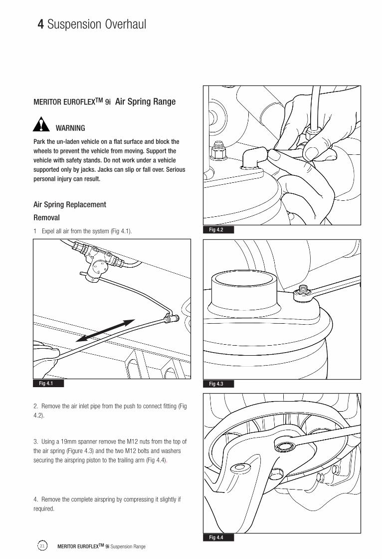
MERITOR EUROFLEXTM 9i Air Spring Range
WARNING
Park the un-laden vehicle on a flat surface and block thewheels to prevent the vehicle from moving. Support thevehicle with safety stands. Do not work under a vehiclesupported only by jacks. Jacks can slip or fall over. Seriouspersonal injury can result.
Air Spring Replacement
Removal
1 Expel all air from the system (Fig 4.1).
2. Remove the air inlet pipe from the push to connect fitting (Fig4.2).
3. Using a 19mm spanner remove the M12 nuts from the top ofthe air spring (Figure 4.3) and the two M12 bolts and washerssecuring the airspring piston to the trailing arm (Fig 4.4).
4. Remove the complete airspring by compressing it slightly ifrequired.
MERITOR EUROFLEXTM 9i Suspension Range21
Fig 4.1
Fig 4.2
Fig 4.3
Fig 4.4

5. Remove the air fitting (Fig 4.5).
Fitting a New Air Spring
1. Fit the air fitting (Fig 4.6).
2. Compress the new air spring and slide into position betweenthe trailing arm platform and the sir spring pedestal.
MERITOR EUROFLEXTM 9i Suspension Range 22
3. Align and locate the air inlet and mounting stud respectively inthe slot and hole on the pedestal (Fig 4.7).
4. Align and locate the lower mounting bolt holes withthe relevant holes in the trailing arm platform (Fig 4.8).
Fit new retaining bolts and washer and tighten to a torque of70Nm.
4 Suspension Overhaul
Fig 4.5
Fig 4.6
Fig 4.7
Fig 4.8

5. Fit new nuts to the upper mounting studs and tighten to atorque of 41Nm (Fig 4.9)
6. Connect the airline (Fig 4.10).
MERITOR EUROFLEXTM 9i Suspension Range23
7. Pressurise the air system (Fig 4.11).
CAUTION
The air spring and connecting pipes must be free frominterference or obstruction by tyres, metal components etc.Damage to components through abrasion will result inpremature failure.
8. Check that tyres, metal components etc. do not interfere withthe air spring, particularly the rubber components.
9. Check all disturbed connections for air leaks.
10. Raise the trailer and remove the safety stands.
11. Verify that the ride height of the trailer is correct. Refer to thetrailer OEM's specification for the correct ride height. Adjustaccordingly following the procedure detailed in the Section 3 RideHeight Adjustment.
4 Suspension Overhaul
Fig 4.9
Fig 4.10
Fig 4.11

WARNING
Verify that people are clear of the trailer before you inflate ordeflate the air springs. The air suspension has various pinchpoints that can cause serious personal injury.
Park the un-laden vehicle on a flat surface and block the wheelsto prevent the vehicle from moving. Support the vehicle with safetystands. Do not work under a vehicle supported only by jacks.Jacks can slip or fall over. Serious personal injury can result.
Check Shock bushings for looseness and wear. Replace worn ordamaged bushes or shock absorbers. Worn or damaged shockabsorbers can lead to reduced ride and handling performance ofthe trailer.
MERITOR EUROFLEXTM 9i Suspension Range 24
Shock Absorber ReplacementArvinMeritor shock absorbers incorporate an integral check strapfeature. However, where the trailer may be subject to a suddenremoval of load e.g. HukePak, axle check straps must be fitted.
CAUTION: Failure to adhere to this may result inserious damage to the suspension and may
invalidate the ArvinMeritor warranty.
MERITOR EUROFLEX 9i Shock Absorber
NOTE: Ensure that when replacing Shock absorbers, the correctsize of Shock absorber is fitted to Lowmount or Topmountsuspension installations.
Lowmount Shock Absorber - 21228392Topmount Shock Absorber - 21228930
NOTE: The protective shroud A on the shock absorber must notbe removed (Fig 4.12).
Shock absorbers must be fitted in the correct orientation. Currentshock absorbers incorporate an adhesive label with the word“TOP” to indicate the correct orientation (Fig 4.12).
NOTE: Early level shock absorbers have an adhesive labelattached indicating the bottom of the shock absorber.
CAUTION: If shock absorbers are fitted in thewrong orientaion there will be a loss of any
suspension damping, causing severe damage to the vehicle.
TM
4 Suspension Overhaul
Fig 4.12
A

Removal
Identify the specific shock absorber that is damaged or leaking.
1. With the trailer in its normal ride height (un-laden) using a 36mm socket and ring spanner, remove the nuts and washers fromthe upper and lower damper bolts (Fig 4.13).
MERITOR EUROFLEXTM 9i Suspension Range25
2. Withdraw the lower mounting bolt (Fig 4.14).
NOTE: On certain applications it may be necessary to removethe brake chamber to provide clearance for lower shock absorbermounting bolt removal. For brake chamber removal instructionsrefer to the appropriate Arvinmeritor brake service manual.
3. Remove the damper from the upper mounting bolt (Fig. 4.15).
NOTE: It is not possible to remove the upper mounting bolt withthe road wheels fitted to the trailer.
4 Suspension Overhaul
Fig 4.13
Fig 4.14
Fig 4.15

Replacement
1. Locate the top eye of the damper on to the upper mountingbolt. Fit a new nut and washer (Fig 4.16).
2. Rotate the damper and slowly pull it to extend its length untilthe lower eye aligns with the mounting hole in the trailing arm. Fitthe lower mounting bolt, flat washer and new nut. Ensure the bolthead is inboard.
3. Using a 36mm socket and ring spanner torque thetwo nuts to 500 Nm (Fig 4.17).
MERITOR EUROFLEXTM 9i Suspension Range 26
NOTE: Ensure suspension is at the ride height setting before fullytightening to torque.
Pivot Bush
CAUTION: Ensure the pips on the replacementPivot Bush are in line with the correct alignment
boss, either T (TOP mount) or L (LOW mount) and the steelplates ‘A’ are aligned front and rear, not top and bottom, asshown in Fig 4.18.
4 Suspension Overhaul
Fig 4.16
Fig 4.17 Fig 4.18
Bush Alignment - Front Arm Orientation
Low Mount
Top Mount
“L” Marked Boss
“T” Marked Boss
A
A
A
A
WARNING
Check pivot bushings for looseness and wear. Replace wornor damaged pivot bushings. Worn bushings can loosen andcause the trailer to wander during operation. Serious injuryand damage to components can result.
Verify that people are clear of the trailer before you inflate ordeflate the air springs. The air suspension has various pinch pointsthat can cause serious personal injury.
Park the un-laden vehicle on a flat surface and block the wheelsto prevent the vehicle from moving. Support the vehicle with safetystands. Do not work under a vehicle supported only by jacks.Jacks can slip or fall over. Serious personal injury can result.
NOTE: This following procedure requires the assistance ofanother person.
Before removal and fitment of pivot bushes;
A genuine ARVINMERITOR pivot bush replacement kit is required.
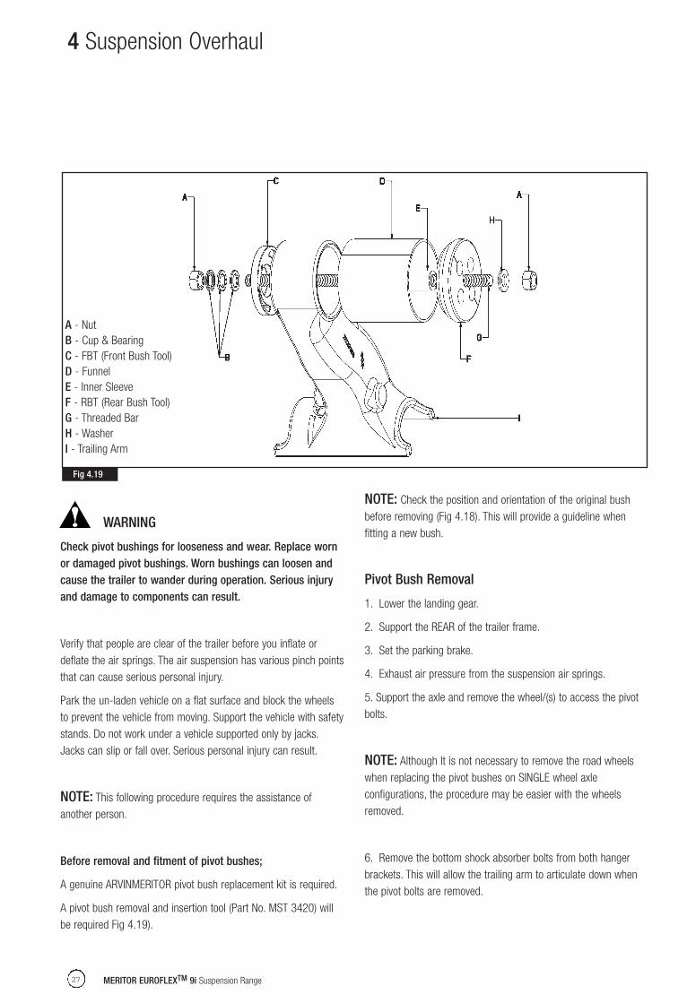
A pivot bush removal and insertion tool (Part No. MST 3420) willbe required Fig 4.19).
MERITOR EUROFLEXTM 9i Suspension Range27
NOTE: Check the position and orientation of the original bushbefore removing (Fig 4.18). This will provide a guideline whenfitting a new bush.
Pivot Bush Removal
1. Lower the landing gear.
2. Support the REAR of the trailer frame.
3. Set the parking brake.
4. Exhaust air pressure from the suspension air springs.
5. Support the axle and remove the wheel/(s) to access the pivotbolts.
NOTE: Although It is not necessary to remove the road wheelswhen replacing the pivot bushes on SINGLE wheel axleconfigurations, the procedure may be easier with the wheelsremoved.
6. Remove the bottom shock absorber bolts from both hangerbrackets. This will allow the trailing arm to articulate down whenthe pivot bolts are removed.
4 Suspension Overhaul
Fig 4.19
A - NutB - Cup & BearingC - FBT (Front Bush Tool)D - FunnelE - Inner SleeveF - RBT (Rear Bush Tool)G - Threaded BarH - WasherI - Trailing Arm
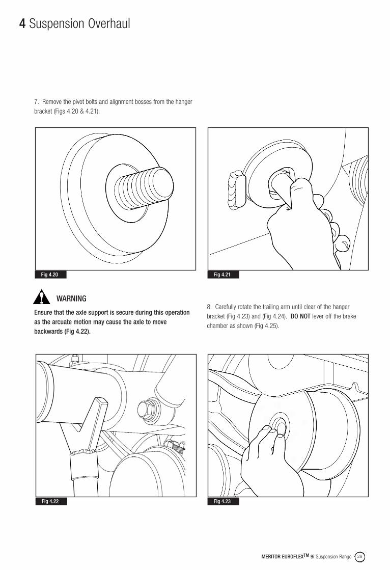
7. Remove the pivot bolts and alignment bosses from the hangerbracket (Figs 4.20 & 4.21).
WARNING
Ensure that the axle support is secure during this operationas the arcuate motion may cause the axle to movebackwards (Fig 4.22).
MERITOR EUROFLEXTM 9i Suspension Range 28
8. Carefully rotate the trailing arm until clear of the hangerbracket (Fig 4.23) and (Fig 4.24). DO NOT lever off the brakechamber as shown (Fig 4.25).
4 Suspension Overhaul
Fig 4.20
Fig 4.22
Fig 4.21
Fig 4.23

9. Remove the wear washers and the steel inner sleeves from thepivot bushes (Figs 4.26 & 4.27).
10. Using the Arvinmerito service tool MST 3420 replace the pivotbushes as described in the following paragraphs .
MERITOR EUROFLEXTM 9i Suspension Range29
11. Insert inner sleeve “E” from the service tool into the pivot bushcentral tube.
4 Suspension Overhaul
Fig 4.24
Fig 4.26
Fig 4.25
Fig 4.27
X

12. Press the Front Bush Tool (FBT) “C” against the pivot bush andinsert the threaded bar “G”. Fit washer “H” and nut “A” to drawbar and secure to FBT “C” (Fig 4.28).
13. Push funnel “D” onto the trailing arm outer tube opposite theFBT “C” (Recess facing towards pivot bush) (Fig 4.29).
MERITOR EUROFLEXTM 9i Suspension Range 30
14. Attach the Rear Bush Tool (RBT) “ F” to the funnel “D” andsecure in place with the bearing cups, bearing race “B” and nut“A” (Fig 4.30)
15. Apply turning moment to the nut “A” at the bearing end,continue turning the nut until the pivot bush is drawn completelyinto the funnel “D” (Fig 4.31).
4 Suspension Overhaul
Fig 4.28
Fig 4.29
Fig 4.30
Fig 4.31

16. Dismantle the tooling and remove the pivot bush from thefunnel “D” (Fig 4.32).
17. Remove any debris that may be left from the trailing arm outertube.
MERITOR EUROFLEXTM 9i Suspension Range31
Pivot Bush Replacement
1. Apply P-80 gel solution around the pivot bush (Fig 4.33), funnel“D” (Fig 4.34) and trailing arm outer tube (Fig 4.35).
4 Suspension Overhaul
Fig 4.32
Fig 4.33
Fig 4.34

2. Insert the replacement pivot bush into the funnel “D” and alignthe pips on the pivot bush with the marked line on the funnel (Fig4.36)
MERITOR EUROFLEXTM 9i Suspension Range 32
3. Fit bush tool to trailing arm as shown (Fig 4.37).
4. Insert inner sleeve “E” into the pivot bush central tube.
5. Press the Rear Bush Tool (RBT) “F” against the trailing armouter tube and insert the threaded bar “G”. Fit washer “H” and nut“A” to draw bar and secure to RBT “F”.
6. Push funnel “D” onto the trailing arm outer tube opposite theRBT “F” (Recess facing towards outer tube). Attach the FBT “C” tothe funnel “D” and secure in place with the bearing cups, bearingrace “B” and nut “A”.
7. Rotate the funnel “D” so that the mark is aligned to the markon the trailing arm (Fig 4.38)
8. Apply turning moment to the nut “A” at the bearing “B” end,continue turning the nut until the pivot bush is drawn completelyinto the trailing arm outer tube. The turning action will lock outwhen the pivot bush mates up with the RBT ”F”.
9. Back off the nut and dismantle the pivot bush tooling. Checkfor any damage to the membrane of the pivot bush.
4 Suspension Overhaul
Fig 4.35
Fig 4.37
Fig 4.36

4 Suspension Overhaul
10. Insert steel inner sleeve "X" into the pivot bush central tube.Fit the replacement wear washers "Y" to either side of the pivotbush (Fig 4.39).
MERITOR EUROFLEXTM 9i Suspension Range33
11. Refit the trailing arm to the hanger bracket (Fig 4.40) andinsert new pivot bolts.
Do not torque the pivot nuts to final torque until the axle is alignedand the trailer is at the ride height with the wheels on. See AxleAlignment - Section 6 and refer to the Ride Height Adjustmentdetails - Section 3.
12. Refit the shock absorber. Do not torque the Shock absorbernuts to final torque until the axle is aligned and the trailer is at theride height with the wheels on. See Axle Alignment Section 6and refer to the Ride Height Adjustment details - Section 3.
13. Refit the wheel (s), where applicable, pressurise the air springsand set ride height.
14 Torque all nuts and bolts to final tightening torque.Refer to Section 8 for torque specification table
Fig 4.39
Fig 4.38
Fig 4.40
X
Y
MERITOR EUROFLEXTM 9i Suspension Range 34
Axle Removal & Replacement
5pg. 35 Axle Removalpg. 36 Axle Replacement

5 Axle Removal & Replacement
NOTE: The MERITOR EUROFLEXTM 9i suspension is an integratedaxle and suspension module. The suspension cannot be removedfrom the axle. Any attempt to do so will seriously damage the axleand suspension and will invalidate the ArvinMeritor warranty.
Removal
1. Ensure no air is left in the system.
2. If spring brakes are fitted they should be released andconstrained using a caging tool.
3a. Drum Brake Trailers - Remove the split pins and clevis pinssecuring the brake chambers to the slack adjuster levers.
3b. Disc Brake Trailers - Remove the brake pipes, leaving thechamber attached to the calliper.
4. If the axle is used to locate the bottom arm, with thesuspension height control valve, remove the eye coupling on thelevelling valve arm from the pin on the axle (Figure 5.1).
MERITOR EUROFLEXTM 9i Suspension Range35
5. Jack up the trailer and support it under the chassis to take theweight of the axle to be removed.
6. Support the axle to be removed on stands such that a pumptrolley or similar device can be slid between them lower the axleonce it is unbolted from the suspension.
7. Remove the wheels from the axle.
8. Using a 36 mm spanner and socket, remove the nut andwasher from the lower damper bolt and withdraw the bolt. Slackenthe top damper bolt nut and pivot the damper upwards to clearthe axle and secure it to the chassis.
9. If required, remove the airspring as detailed in Section 3.
For single axle trailers and rear axles of tandems and tri-axlesproceed as follows;
10. Using a 36 mm spanner and socket, slacken the two mainpivot bolt nuts just enough to allow the arms to easily pivot.
11. Slide trolley jacks as required under the axle, jack them up totake the weight of the stands. Remove the stand and lower thejacks. Pull the axle clear backwards and clear of the trailer.
For the front axle of a tandem and the centre or the front axle on atriaxles trailer proceed as follows;
12. Using a 36 mm spanner and socket, remove the two mainpivot nuts and washers and remove the bolts ensure the arms aresupported to prevent them dropping.
13. Slide trolley jacks as required under the axle and take the axleweight. Remove the axle stands and slide the axle out sideways.
Fig 5.1
Replacement
If the original axle and suspension unit is not refitted, thereplacement must be supplied and approved by ARVINMERITOR.
If in doubt contact the ARVINMERITOR Technical Sales Departmentfor detailed recommendations.
1. Lift axle onto trolley jacks and rotate to ensure it's correctlyoriented.
2. For single axle trailers and rear axles of tandems and triaxlesslide the axle and suspension unit sideways into position, andplace the arms eye ends in the position in the frame brackets.
3. Align the holes in the arm bushes - ENSURE NO GREASE ISON THE THREADS. Fit the bolts, washers,wear washers, bushinner sleeves and nuts and tighten such that the arms can pivoteasily.
Continue for all models as follows:
4. Lower/raise the axle and trailing arm until the hole in the lowerdamper bush is aligned with the location hole in the arm, if the oldbolts are being re-used ,ensure they are clean (especially thethreads) and undamaged - ENSURE NO GREASE IS ONTHREADS.
Re-fit the bolts.
5. Fit new nuts and washers, do not tighten at this stage.
6. If required, re-fit the air spring as detailed in Section 3.
7. Lower/raise the axle and arms until the axle is in the rideheight position (see section 1). IT IS VERY IMPORTANT THAT THEDAMPER AND PIVOT BOLTS ARE FULLY TIGHTEND WHEN AXLEIS IN THE RIDE HIEGHT POSITION. Torque up the top and bottomdamper bolts using a 36mm spanner and socket and the pivotbolts. Refer to torque tables - Section 8.
MERITOR EUROFLEXTM 9i Suspension Range 36
8. Drum Brake Trailers-refit the brake chambers on the airchamber brackets and secure using the original nuts ifundamaged, ideally new nuts and washers should be used, ensurenuts and washers are clean.
9. Disc Brake Trailers-reconnect the brake pipes.
10. Refit the clevis and split pins in the slack adjuster levers andremove the spring cages if spring brakes are fitted. Check thebrake adjustment as detailed in the ARVINMERITOR axle servicemanual.
11. Refit the road wheels and lower trailer chassis and axle offtheir support stands.
5 Axle Removal & Replacement

MERITOR EUROFLEXTM 9i Suspension Range37

MERITOR EUROFLEXTM 9i Suspension Range 38
Axle Alignment (Tracking)
6pg. 39 Before you Align Axlepg. 39 Front Axlepg. 39 Rear Axle

6 Axle Alignment
This section provides details of how to re-align suspensions if theirsettings are changed due to other work.
All MERITOR EUROFLEXTM 9i models are available with thepatented pivot eye tracking facility. This is re-usable and does notrequire welding, and offers +/- 7 mm of fore and aft movement.
It is recommended that tracking is performed before painting, andthat no debris is left in the clamped faces of the joint.
Before you align the Axle
1. The trailer must be on a level surface and un-laden.
2. Adjust the trailer landing gear: The height of the king pin shouldbe the same as when the trailer is connected.
3. Support the chassis on suitable axle stands
4. Expel all air from the system.
5. Remove the road wheels.
Front Axle
1. Verify that the suspension is at the correct ride height. Refer toRide Height Adjustment - Section 3
2. Measure from the king pin to each end of the first axle(measurement DR and DL. To obtain correct alignment, settings(Figs 6.2 & 6.3).
NOTE: Rotate the hub backwards and forwards to ensure that themeasurement is the maximum possible.
If Adjustment is required: Proceed to step 3 below. If Adjustment isnot required: Proceed to 'Rear Axle' in this section.
NOTE: Before you align an axle, ensure the pivot bolt is free tomove in the adjustment slot.
MERITOR EUROFLEXTM 9i Suspension Range39
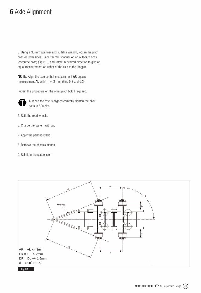
3. Using a 36 mm spanner and suitable wrench, loosen the pivotbolts on both sides. Place 36 mm spanner on an outboard boss(eccentric boss) (Fig 6.1), and rotate in desired direction to give anequal measurement on either of the axle to the kingpin.
NOTE: To obtain correct alignment, the dimensions DR and DLmust be within +/- 3mm at both ends of the axle (Figs 6.2 & 6.3).
Repeat the procedure on the other pivot bolt if required.When the desired measurements have been achieved,tighten pivot bolts to 800 Nm.
Rear Axle
1. Check the dimension from the centerline of the front axle to thecenterline of the rear axle (measurements AR and AL).
2. To obtain correct alignment, the dimensions must be within +/-3mm at both ends of the axle. (Figs 6.2 and 6.3). If Adjustmentis required: Proceed to step 3 below. If Adjustment is not required:Proceed to step 4.
NOTE: Before you align an axle, ensure the pivot bolt is free tomove in the adjustment slot.
Fig 6.1
3. Using a 36 mm spanner and suitable wrench, loosen the pivotbolts on both sides. Place 36 mm spanner on an outboard boss(eccentric boss) (Fig 6.1), and rotate in desired direction to give anequal measurement on either of the axle to the kingpin.
NOTE: Align the axle so that measurement AR equalsmeasurement AL within +/- 3 mm. (Figs 6.2 and 6.3)
Repeat the procedure on the other pivot bolt if required.
4. When the axle is aligned correctly, tighten the pivotbolts to 800 Nm.
5. Refit the road wheels.
6. Charge the system with air.
7. Apply the parking brake.
8. Remove the chassis stands
9. Reinflate the suspension
MERITOR EUROFLEXTM 9i Suspension Range 40
6 Axle Alignment
Fig 6.2
AR = AL +/- 3mmLR = LL +/- 2mmDR = DL +/- 1.5mm0 = 90
o+/- 1/6
o

6 Axle Alignment
MERITOR EUROFLEXTM 9i Suspension Range41
Fig 6.3
AR = AL +/- 3mmBR = BL +/- 3mmLR = LL +/- 2mmDR = DL +/- 1.5mm0 = 90
o+/- 1/6
o

MERITOR EUROFLEXTM 9i Suspension Range 42
Axle & Suspension Welding Recommendations
7pg. 43 Axle & Suspension Welding Recommendations

7 Axle & Suspension Welding Recommendations
MERITOR EUROFLEXTM 9i Suspension Range43
WARNING: To prevent serious eye injury, alwayswear always wear safe eye protection when youperform vehicle maintenance or service.
Incorrect weld placement will void ARVINMERITOR's warranty andcan reduce the fatigue life of the trailer axle beam and suspensioncomponents. Serious personal injury can result.
The suspension and axle must be protected from heat and weldspatter to avoid damage and any plastic or rubber componentsmust be properly covered. All parts must be dry and free from oiland dirt prior to welding. Ensure that the suspension is properlyearthed to avoid arcing.
WARNING: Incorrect weld placement, or weldspatter, can result in reduced fatigue life of the
suspension system, serious personal injury and damage tocomponents.
For further information refer to the ROR Care website atwww.RORCare.com
Refer to the MERITOR EUROFLEXTM 9i Suspension GeneralAssembly Drawings for further details.

MERITOR EUROFLEXTM 9i Suspension Range 44
Maintenance Schedules
8pg. 45 Maintenance Schedulespg. 46 Table of Torque Values

8 Maintenance Schedules
After First 1000 KM
Check all fastener torques and tighten where required accordingto the values in the table in this section.
Examine all valves and air hose joints for leaks or signs of pipework rubbing against the chassis or suspension components.
Check the suspension ride height as explained in Section 3.
Inspect the dampers for evidence of oil leaks.
If an axle lift is fitted, check that it is functioning correctly.
Check the operation of all optional equipment and test for air leakson air system equipment. Individual service manuals should bereferred to if required.
Check arms and welds for cracks in all inspection intervals stated.
After First 10000 KM & Subsequent 10,000 KMIntervals
Inspect the dampers for evidence of oil leaks and inspect thedamper bushes for signs of rubber extrusion or damage.
Check the airsprings for signs of leakage and examine the rubberbellows for signs of damage from road debris or internal bumpstop failure.
Check all pipe joints for signs of leakage and ensure that novalves are fouled with road dirt such that their operation may beimpaired. This is especially relevant to the levelling valve. This isparticularly important if the trailer has been operated in a harshenvironment e.g. coal, dust, quarries etc.
If an axle lift is fitted, check it is operating correctly.
MERITOR EUROFLEXTM 9i Suspension Range45
Check the operation of all optional equipment and test for air leakson air system equipment. Individual service manuals should bereferred to if required.
Examine tyres for uneven wear. If there is any present check thepivot bushes for damage and re-check the axle alignment asdetailed in Section 6.
If damage is found then the trailing arms should be removed asdetailed in Section 4 and replacement of the bush and possiblythe wear plates is advised. Failure to do so may result in tyre wearor structural damage.
Check all fastener torques and tighten where required accordingto the values in the table in this section.
If an axle lift assembly is fitted ensure it is operating correctly.Check the extra air springs (if fitted) are operating as the axle isbeing raised. For detailed information refer to the Arvinmeritor LiftAxle manual
Check arms and welds for cracks in all inspection intervals stated.
Every 100,000 KM
Check the dampers for oil leaks along their body. Lever betweenthe damper eye ends (top and bottom) and close bracketry toensure no excessive lateral movement exists indicating bushfailure or loose bolts.
Check the airsprings for air leaks and signs of damage especiallyto the rubber bellows. Details of replacing them can be found inSection 4.
Uncouple the levelling valve arm/axle rubber joint and raise andlower the arm to check that the valve is passing air in and out ofthe suspension system.

Check the pressure protection valve by draining the brake andsuspension air tanks and couple up an air pressure gauge to eachtank. With an air supply of 6.5 bar, recharge the tanks. The braketank pressure should reach 5.5 bar minimum before thesuspension tank begins to charge.
Clean under the suspension inside the hanger brackets andaround the trailing arm pivots. Check between the wear plates onthe inside faces of the hanger brackets and the trailing arms forsigns of excessive wear or damage to the rubber pivot bushes.
All torques must be within ±5% of stated values.
Check arms and welds for cracks in all inspection intervals stated.
WARNING
Check fastener torque values, tighten loose fasteners andreplace damaged fasteners. Loose, damaged or missingfasteners can cause loss of vehicle control, death, seriouspersonal injury and damage to components.
Table of Torques Fasteners
Fastener Description Torque (Nm) +/- 5%
Pivot Nut 800 *
Shock Absorber Nut (Top & Bottom) 500 *
Upper Air spring nut (M12) 41
Lower Air spring Screw (M12) 70
NOTE: * Do not torque the Pivot Nut or Shock Absorber nuts tofinal torque until the axle is aligned and the trailer is at the rideheight with the wheels on. Refer to Axle Alignment - Section 6(Figs 6.2 & 6.3) and Ride Height Adjustment - Section 3
MERITOR EUROFLEXTM 9i Suspension Range 46
8 Maintenance Schedules

MERITOR EUROFLEXTM 9i Suspension Range47

MERITOR EUROFLEXTM 9i Suspension Range 48
Fault Finding & Diagnostics
9pg. 49 Braking Problemspg. 49 Tyre Wearpg. 49 Excessive Rollpg. 49 Suspension Related Problemspg. 50 Axle Lift Problemspg. 50 Fault Diagnostic Table

9 Fault Finding & Diagnostics
This section is intended to give a guide to the trailer operator toenable him to assess problems. The range of problems andsuggested causes and cures are by no means complete but areintended to provide a solution to the most commonly encountereddifficulties.
NOTE: IF THE OPERATOR IS IN DOUBT ABOUT THE SAFETY OFTHE VEHICLE HE SHOULD NOT OPERATE IT, AND SHOULDIMMEDIATELY SEEK QUALIFIED ADVICE FROM ARVINMERITOR.
How to use this section.
The faults are listed under five main headings, namely
1. BRAKING PROBLEMS
2. TYRE WEAR
3. EXCESSIVE ROLL
4. SUSPENSION AIR RELATED PROBLEMS
5. AXLE LIFT RELATED PROBLEMS
Listed under each of these headings are the likely specificproblems, each followed by a check procedure which shouldhighlight the cause of the problem. If the problem cannot besolved after working through the relevant check list, then furtherinformation should be obtained from ARVINMERITOR.
Braking Problems
If brakes are not functioning correctly:
• Check that there is at least 6.5 bar at coupling head, and thecorrect ratio of air is delivered to the brake chamber.
• Check slack adjusters are correctly adjusted
• Ensure all brake system valves are functioning correctly
IF PROBLEM PERSISTS SEE ARVINMERITOR AXLE AND BRAKESERVICE MANUALS FOR FULL BRAKE SERVICE PROCEDURE.OR SEE WWW.RORCare.COM
MERITOR EUROFLEXTM 9i Suspension Range49
Tyre Wear
If tyre wear is excessive:
• Check axle alignment is correct
• Check wheels are parallel (i.e. zero camber and toe in/out)
• Inspect the trailing arm pivot bushes for damage, and replace ifnecessary
• Check shock absorber for oil leaks
• Inspect shock absorber bushes for damage
• Ensure ride height is set correctly
• Check application, operation and route.
• Ensure no axle is lifted when trailer is fully loaded.
Excessive Roll
If trailer is rolling excessively:
• Check pivot bolt torque is correct
• Check pivot bush condition.
• Check axle and suspension trailing arms for cracks.
Is centre of gravity excessive ?
• Ensure ride height is set correctly
• If vehicle is load sensed, check that a shuttle valve is fitted toprevent cross coupling. Fit if necessary
Suspension Air Related Problems
If suspension will not inflate:
• Check that the levelling valve is connected to the axle
• Ensure the brake air reservoir pressure is more than 6.5 bar
• Ensure the suspension air reservoir pressure is at least 6.5 bar
• Check the setting of the pressure protection valve and clean theair filter
• Check the axle load is not greater than the available pressure
• Check all pipework and fittings for leaks using soapy water
• Check the airsprings for leaks using soapy water

• Check levelling valve for leakage at the exhaust port, and ifnecessary replace valve If suspension is deflating:
• Check all pipework and fittings for leaks using soapy water
• Check the airsprings for leaks using soapy water
• Check levelling valve for leakage at the exhaust port, and ifnecessary replace the valve
Axle Lift Related Problems
If lift will not operate:
• Work through check procedure for main suspension airspringsnot inflating.
• Check that the lift valve is correctly installed and piped. Replacevalve if faulty.
For detailed information refer to the Arvinmeritor Lift Axle manual
Fault Diagnostic Table
MERITOR EUROFLEXTM 9i Suspension Range 50
9 Fault Finding & Diagnostics
Condition Possible Cause Recommended ActionAll air springs flat 1 Insufficient air pressure to
suspension air springs.Build air pressure to 6.5 Bar, ormore. Check compressor forcorrect function. Check all air linesand fittings forleaks.
2 Defective pressure protectionvalve.
Check and replace valve ifnecessary.
3 Height control valve supply ordelivery fitting clogged.
Inspect height control valve supply& delivery fittings for restrictions.
4 Air leak in system Inspect entire system for leaks.Repair orreplace as necessary.
5 Suspension overloaded. Review load to suspension ratedcapacity
Air springs fully raised but do notexhaust
1 Height control valve delivery port orexhaust port plugged.
Inspect port for restrictions. Repairor replace as necessary.
2 Height control linkage broken Replace linkage.
Vehicle body incorrect ride height duringoperation
1 Height control valve not adjustedproperly
Inspect and adjust as necessary.
2 Height control lever bent orbroken
Straighten or replace lever.

MERITOR EUROFLEXTM 9i Suspension Range51
9 Fault Finding & Diagnostics
Condition Possible Cause Recommended ActionVehicle body incorrect ride height duringoperation
3 Insufficient air pressure to thesuspension system.
Check air compressor and pressureprotection valve for proper operation.Inspect system for leaks. Repair andreplace as necessary.
Main air pressure drops to 6.5 Bar 1 Ruptured air spring Inspect air springs and replace asnecessary.
2 Leaking air lines Insperct air lines and repair or replaceas necessary.
Hard Ride 1 Improper ride height or airsprings flat
Check and adjust ride height. See firstcondition
Suspension ride height not maintainedduring operation
1 Clogged air filters Inspect and clean or replace as necessary.
2 Moisture in air tank Drain air tank and evacute air systemof moisture.
3 Clogged filter screens inheight control valve
Inspect and clean or replace as necessary.
4 Damaged linkage or incorrectvalve mounting
Replace, repair or adjust as necessary.
Incorrect tyre clearance in full bounce 1 Incorrect tyre size Replace tires with the recommendedtyre size.
Trailer not pulling straight (dog-walk) 1 Trailer axles out of alignment Realign axles
2 Loose alignment bosses orpivot bolt
Align axles and tighten pivot bolts tothe correct torque.
Trailer wandering or unusual rattling 1 Worn bushings Inspect bushings and replace asneeded
Broken Shock Absorbers 1 Trailer fitted with manualraise/lower valve. Driverforgets to set to ride height
Fit auto raise/lower device.Driver education.
2 Auto reset fitted, checkfunction of Colas/EBS tractor iscompatible
Check operation
3 Is trailer towed on sit withDock spotter etc.
Check operation
4 Incorrect King pin height Set Kingpin height to recommendedvalues from trailer plate details orcontact manufacturer
Air spring bump stop broken 1 Trailer driven with no air in thesuspension
Driver education
Damage to lifter in red emergency coupling atheadboard of trailer
1 Dirt in air system. Check operation. Replace worn lifter incoupling
2 General wear and tear

For further information contact
Meritor HVS Limited Meritor HVS Limited
Commercial Vehicle Systems Commercial Vehicle Systems
Rackery Lane, Llay Grange Road
Wrexham LL12 0PB Cwmbran, NP44 3XU
U.K. U.K.
Telephone: +44 (0)1978 852141 Telephone: +44 (0)1633 834 040
www.arvinmeritor.com
www.RORCare.com
© 2009 ArvinMeritor, Inc.
Meritor Automotive
All rights Reserved
Publication: MM-0556
Descriptions and specifications were in effect at the
time of this publication and are subject to change
without notice or liability. Meritor reserve the right to
make design improvements, change or discontinue
parts at any time