MAINTENANCE MANUAL FOR JABIRU 2200 AIRCRAFT...
94
MAINTENANCE MANUAL FOR JABIRU 2200 AIRCRAFT ENGINE JABIRU 3300 AIRCRAFT ENGINE DOCUMENT No. JEM0002-1 DATED: 26 th July 2012 This Manual has been prepared as a guide to correctly operate, maintain and service Jabiru 2200 & 3300 engines. It is the owner's responsibility to regularly check the Jabiru web site at www.jabiru.net.au for applicable Service Bulletins and have them implemented as soon as possible. Failure to do this may render the aircraft un-airworthy and void Jabiru’s Limited, Express Warranty. This document is controlled while it remains on the Jabiru server. Once this no longer applies the document becomes uncontrolled. Should you have any questions or doubts about the contents of this manual, please contact Jabiru Aircraft Pty Ltd.
Transcript of MAINTENANCE MANUAL FOR JABIRU 2200 AIRCRAFT...

MAINTENANCE MANUAL FOR
JABIRU 2200 AIRCRAFT ENGINE JABIRU 3300 AIRCRAFT ENGINE
DOCUMENT No. JEM0002-1
DATED: 26th
July 2012
This Manual has been prepared as a guide to correctly operate, maintain and service Jabiru 2200 & 3300 engines.
It is the owner's responsibility to regularly check the Jabiru web site at
www.jabiru.net.au for applicable Service Bulletins and have them
implemented as soon as possible. Failure to do this may render the aircraft un-airworthy and void Jabiru’s Limited, Express Warranty.
This document is controlled while it remains on the Jabiru server. Once this no longer applies the document becomes uncontrolled.
Should you have any questions or doubts about the contents of this manual, please contact Jabiru Aircraft Pty Ltd.

Engine Maintenance Manual Jabiru Aircraft Pty Ltd
JEM0002-1 Jabiru Model 2200 & 3300 Aircraft Engines
This document is controlled while it remains on the Jabiru server. Once this no longer applies the document becomes uncontrolled.
ISSUE 1 Dated : 26th July 2012 Issued By: DPS Page: 2 of 94
C:\Aero_Craft_Australia\Jabiru\Jabiru_Documents_Edited\2200-3300_Engine_Maintenance_Manual\JEM0002-1_Maint_22-33_unsigned.docx
1.1 TABLE OF FIGURES .................................................................................................................................5
2 GENERAL INFORMATION ...................................................................................................... 6
2.1 LIST OF EFFECTIVE PAGES ......................................................................................................................6 2.2 INTRODUCTION .......................................................................................................................................7 2.3 DESCRIPTION .........................................................................................................................................7 2.4 APPLICABILITY ........................................................................................................................................9 2.5 READING THIS MANUAL ..........................................................................................................................9 2.6 DEGREE OF DIFFICULTY .........................................................................................................................9 2.7 ADDITIONAL SERVICE INFORMATION ........................................................................................................9 2.8 RECORDING ........................................................................................................................................ 10 2.9 MANUFACTURER .................................................................................................................................. 10 2.10 ENGINE MANUALS ............................................................................................................................ 10
3 SPECIFICATIONS ................................................................................................................. 11
3.1 2200 ENGINE MODELS ........................................................................................................................ 11 3.1.1 2200J......................................................................................................................................................... 11 3.1.2 2200B ........................................................................................................................................................ 11 3.1.3 2200C ........................................................................................................................................................ 11 3.1.4 2200A ........................................................................................................................................................ 11
3.2 3300 ENGINE MODELS ........................................................................................................................ 12 3.2.1 3300L ........................................................................................................................................................ 12 3.2.2 3300A ........................................................................................................................................................ 12
3.3 DESIGN DETAILS ................................................................................................................................. 13 3.4 GENERAL SPECIFICATIONS & EQUIPMENT ............................................................................................. 14 3.5 FULL POWER STATIC RPM .................................................................................................................. 15 3.6 PERFORMANCE ................................................................................................................................... 15
3.6.1 Engine Ratings .......................................................................................................................................... 15 3.7 FUEL ................................................................................................................................................... 15
3.7.1 Recommended Fuel Types: ...................................................................................................................... 15 3.7.2 Fuel Consumption: .................................................................................................................................... 16
3.8 LUBRICANT .......................................................................................................................................... 16 3.9 COOLING SYSTEM ............................................................................................................................... 17 3.10 OPERATING SPEEDS AND LIMITS ....................................................................................................... 18
3.10.1 Ground Operating Limits ........................................................................................................................... 18 3.10.2 In-Flight Operating Limits .......................................................................................................................... 18
3.11 TORQUE SPECIFICATIONS ................................................................................................................. 19 3.12 PROPELLER SELECTION & SPECIFICATIONS ....................................................................................... 19 3.13 ELECTRICAL SYSTEM SPECIFICATIONS .............................................................................................. 20 3.14 2200 – DIMENSIONS ........................................................................................................................ 21 3.15 2200 – DENOMINATION OF CYLINDERS ............................................................................................. 21 3.16 3300 – DIMENSIONS ........................................................................................................................ 22 3.17 3300 – DENOMINATION OF CYLINDERS ............................................................................................. 22 3.18 DISTRIBUTOR CYLINDER MAP ........................................................................................................... 23 3.19 2200 – POWER CURVE .................................................................................................................... 23 3.20 3300 – POWER CURVE .................................................................................................................... 24
4 OPERATING INSTRUCTIONS ............................................................................................... 25
4.1 DAILY CHECKS .................................................................................................................................... 25 4.2 STARTING PROCEDURE ........................................................................................................................ 25
4.2.1 Cold Engine ............................................................................................................................................... 26 4.2.2 Warm Engine ............................................................................................................................................. 26
4.3 WARMING UP PERIOD .......................................................................................................................... 26 4.4 GROUND RUNNING .............................................................................................................................. 26 4.5 TAKE-OFF ........................................................................................................................................... 26 4.6 ENGINE STOP ...................................................................................................................................... 26 4.7 ENGINE STOP AND START DURING FLIGHT ............................................................................................ 27 4.8 OPERATION IN WINTER ........................................................................................................................ 27 4.9 CARBURETTOR ICING ........................................................................................................................... 27
4.9.1 Icing Due to Water in fuel .......................................................................................................................... 27 4.9.2 Icing Due to High Air Humidity. .................................................................................................................. 27
4.10 NEW ENGINE OPERATION ................................................................................................................. 27 4.11 ENGINE INSTALLATION ...................................................................................................................... 28

Engine Maintenance Manual Jabiru Aircraft Pty Ltd
JEM0002-1 Jabiru Model 2200 & 3300 Aircraft Engines
This document is controlled while it remains on the Jabiru server. Once this no longer applies the document becomes uncontrolled.
ISSUE 1 Dated : 26th July 2012 Issued By: DPS Page: 3 of 94
C:\Aero_Craft_Australia\Jabiru\Jabiru_Documents_Edited\2200-3300_Engine_Maintenance_Manual\JEM0002-1_Maint_22-33_unsigned.docx
5 MAINTAINER REQUIREMENTS ........................................................................................... 29
5.1 FACILITIES ........................................................................................................................................... 29 5.2 TRAINING ............................................................................................................................................ 29 5.3 RATING ............................................................................................................................................... 29 5.4 EXPERIENCE ....................................................................................................................................... 29 5.5 TOOL & GAUGE CONTROL .................................................................................................................... 29 5.6 TOOLS: ............................................................................................................................................... 29 5.7 EQUIPMENT: ........................................................................................................................................ 30 5.8 GENERAL: ........................................................................................................................................... 30 5.9 SEALANTS AND COMPOUNDS ............................................................................................................... 31 5.10 LOCTITE 620 & OTHER RETAINING COMPOUNDS ............................................................................... 33 5.11 SPECIAL TOOLS ............................................................................................................................... 34 5.12 TORQUE / TENSION WRENCH ............................................................................................................ 37 5.13 TORQUE APPLICATION PROCEDURE .................................................................................................. 39
6 STORAGE & CLEANING ....................................................................................................... 40
6.1 PARKING ............................................................................................................................................. 40 6.2 STORAGE ......................................................................................................................................... 40
6.2.1 Flyable Storage ......................................................................................................................................... 40 6.2.2 Returning Engine to Service From Flyable Storage .................................................................................. 40 6.2.3 Temporary or Indefinite Storage ................................................................................................................ 40 6.2.4 Inspection During Storage ......................................................................................................................... 41 6.2.5 Returning Engine to Service After Temporary / Indefinite Storage ............................................................ 41 6.2.6 New Engine Storage ................................................................................................................................. 42
6.3 CLEANING ENGINE AND ENGINE COMPARTMENT ..................................................................... 42
7 MAINTENANCE ..................................................................................................................... 43
7.1 SERVICE INTERVAL TOLERANCE ........................................................................................................... 43 7.2 BASIC INSPECTION PROCEDURE ........................................................................................................... 43 7.3 WORK SHEETS .................................................................................................................................... 43 7.4 MANDATORY INSPECTIONS & LIFED ITEMS. ........................................................................................... 43
7.4.1 Flexible Hoses ........................................................................................................................................... 43 7.5 ENGINE INSPECTION CHART ................................................................................................................. 43 7.6 PRE-MAINTENANCE INSPECTIONS: ....................................................................................................... 46 7.7 PROPELLER – INSPECTION DETAILS ...................................................................................................... 47 7.8 ENGINE & ENGINE COMPARTMENT – INSPECTION DETAILS .................................................................... 47 7.9 FUEL SYSTEM – INSPECTION DETAILS................................................................................................... 49 7.10 SPECIAL MAINTENANCE - CHECK AFTER INITIAL 5 HOURS – SOLID LIFTER ONLY ................................. 49 7.11 SPECIAL MAINTENANCE - CHECK AFTER INITIAL 10 HOURS ................................................................. 50 7.12 SPECIAL INSPECTION - CHECK AFTER INITIAL 25 HOURS .................................................................... 50 7.13 SPECIAL INSPECTION - CHECK AFTER INITIAL 50 HOURS .................................................................... 50 7.14 SPECIAL MAINTENANCE – NON-APPROVED PROPELLERS ................................................................... 51
8 SERVICE & REPAIR PROCEDURES .................................................................................... 53
8.1 ENGINE TEST RUN ............................................................................................................................... 53 8.2 PROPELLER TRACKING ........................................................................................................................ 53 8.3 SPINNER INSPECTIONS ........................................................................................................................ 54 8.4 RAM AIR DUCT INSPECTIONS ............................................................................................................... 54 8.5 OIL & FILTER CHANGE ......................................................................................................................... 55 8.6 OIL PRESSURE RELIEF VALVE ADJUSTMENT ......................................................................................... 55 8.7 AIR INTAKE FILTER .............................................................................................................................. 56 8.8 IGNITION COIL GAP ADJUSTMENT ......................................................................................................... 57 8.9 HIGH TENSION LEAD INSPECTION & MAINTENANCE ............................................................................... 57 8.10 SPARK PLUGS ................................................................................................................................. 58 8.11 CARBURETTOR INSPECTION & ADJUSTMENT ...................................................................................... 58
8.11.1 Tuning ....................................................................................................................................................... 59 8.12 DISTRIBUTOR & ROTOR INSPECTION & ADJUSTMENT ......................................................................... 60 8.13 FUEL SYSTEM .................................................................................................................................. 61 8.14 TACHOMETER AND SENDER .............................................................................................................. 62 8.15 HEAD BOLT TENSION CHECK ............................................................................................................ 63 8.16 VALVE CLEARANCE ADJUSTMENT (SOLID LIFTER ENGINES ONLY) ...................................................... 64
CAUTION ..................................................................................................................................... 64

Engine Maintenance Manual Jabiru Aircraft Pty Ltd
JEM0002-1 Jabiru Model 2200 & 3300 Aircraft Engines
This document is controlled while it remains on the Jabiru server. Once this no longer applies the document becomes uncontrolled.
ISSUE 1 Dated : 26th July 2012 Issued By: DPS Page: 4 of 94
C:\Aero_Craft_Australia\Jabiru\Jabiru_Documents_Edited\2200-3300_Engine_Maintenance_Manual\JEM0002-1_Maint_22-33_unsigned.docx
8.17 COMPRESSION CHECK ..................................................................................................................... 65 8.17.1 Compression Gauge: ................................................................................................................................ 65 8.17.2 Pressure Differential Test: ......................................................................................................................... 65 8.17.3 Identifying Compression Leaks ................................................................................................................. 65
8.18 FUEL FLOW RATE TEST .................................................................................................................... 66 8.19 HYDRAULIC VALVE LIFTER MAINTENANCE ......................................................................................... 66
8.19.1 Hydraulic Lifter Removal ........................................................................................................................... 67 8.19.2 Valve Rockers ........................................................................................................................................... 67
8.20 IGNITION COIL & ALTERNATOR ELECTRICAL INSPECTIONS .................................................................. 68 8.21 FLYWHEEL SCREW INSPECTION ........................................................................................................ 68 8.22 USE OF SAFETY WIRE ...................................................................................................................... 69 8.23 ENGINE OVERHAUL AND TBO ........................................................................................................... 71
8.23.1 Full Overhaul ............................................................................................................................................. 71 8.23.2 Top End Overhaul ..................................................................................................................................... 71
8.24 ENGINE REMOVAL PROCEDURE ........................................................................................................ 72 8.25 ENGINE INSTALLATION ...................................................................................................................... 73 8.26 PROP STRIKE INSPECTION ................................................................................................................ 74 8.27 PROPELLER FLANGE INSTALLATION / REMOVAL ................................................................................. 75
9 TROUBLE SHOOTING .......................................................................................................... 76
9.1 ENGINE WON'T START ......................................................................................................................... 76 9.2 ENGINE IDLES UNSTEADILY AFTER WARM-UP PERIOD: SMOKY EXHAUST ............................................... 76 9.3 ENGINE RUNS ERRATICALLY OR MISFIRES OCCASIONALLY .................................................................... 76 9.4 FULL POWER STATIC RPM BELOW SPECIFICATIONS ............................................................................. 76
9.5 ENGINE RUNS TOO HOT - OIL TEMPERATURE ABOVE 110OC (230OF) ................................................... 77
9.6 CHT READING ERROR ......................................................................................................................... 77 9.7 UNSATISFACTORY POWER OUTPUT ...................................................................................................... 77 9.8 LOW OIL PRESSURE ............................................................................................................................ 78 9.9 OIL PRESSURE VARYING ...................................................................................................................... 78 9.10 ENGINE KEEPS RUNNING WITH IGNITION OFF .................................................................................... 78 9.11 EXCESSIVE OIL CONSUMPTION ......................................................................................................... 78 9.12 OIL COLLECTOR BOTTLE ON FIREWALL FILLS QUICKLY ...................................................................... 78 9.13 EXCESSIVE VIBRATION ..................................................................................................................... 79 9.14 KNOCKING UNDER LOAD .................................................................................................................. 79 9.15 ENGINE HARD TO START AT LOW TEMPERATURE – COLD START CHECKLIST ...................................... 80 9.16 IRREGULAR / LOW COMPRESSIONS ................................................................................................... 81 9.17 HYDRAULIC VALVE LIFTERS .............................................................................................................. 82
10 AIRWORTHINESS LIMITATIONS SECTION ......................................................................... 83
11 MAINTENANCE WORKSHEETS ........................................................................................... 84
11.1 25-HOUR WORKSHEET .................................................................................................................... 84 11.2 50-HOUR WORKSHEET .................................................................................................................... 84 11.3 100-HOUR WORKSHEET .................................................................................................................. 85 11.4 200-HOUR WORKSHEET .................................................................................................................. 86 11.5 ANNUAL WORKSHEET ...................................................................................................................... 87
12 NEW ENGINE – JABIRU’S LIMITED, EXPRESS WARRANTY ............................................. 88
13 JABIRU’S LIMITED, EXPRESS WARRANTY: CLAIM FORM ............................................... 94

Engine Maintenance Manual Jabiru Aircraft Pty Ltd
JEM0002-1 Jabiru Model 2200 & 3300 Aircraft Engines
This document is controlled while it remains on the Jabiru server. Once this no longer applies the document becomes uncontrolled.
ISSUE 1 Dated : 26th July 2012 Issued By: DPS Page: 5 of 94
C:\Aero_Craft_Australia\Jabiru\Jabiru_Documents_Edited\2200-3300_Engine_Maintenance_Manual\JEM0002-1_Maint_22-33_unsigned.docx
1.1 Table of Figures Figure 1 – Oil System Schematic .................................................................................................................... 17 Figure 2 – 2200 Engine Dimensions ............................................................................................................... 21 Figure 3 – 2200 Cylinder Denomination & Firing Order .................................................................................. 21 Figure 4 – 3300 Engine Dimensions ............................................................................................................... 22 Figure 5 – 3300 Cylinder Denomination & Firing Order .................................................................................. 22 Figure 6 – Distributor Cylinder Map ................................................................................................................. 23 Figure 7 – Power / Torque Curve – Typical 2200A Engine ............................................................................. 23 Figure 8 – Power Curve - Typical 2200C, 2200B, Engine ............................................................................... 24 Figure 9 – Power / Torque Curves – Typical 3300 Engine .............................................................................. 24 Figure 10 – Sealants, Compounds & Lubricants #1 ........................................................................................ 31 Figure 11 – Sealants, Compounds & Lubricants #2 ........................................................................................ 31 Figure 12 – Sealants, Compounds & Lubricants #4 ........................................................................................ 32 Figure 13 – Sealants, Compounds & Lubricants #4 ........................................................................................ 32 Figure 14 – Sealants, Compounds & Lubricants #3 ........................................................................................ 33 Figure 15 – Valve Compressor / Lifter Bleed Tools ......................................................................................... 34 Figure 16 – Dimensional Details For Lifter Tool .............................................................................................. 34 Figure 17 – Valve Leakage Vacuum Tester .................................................................................................... 34 Figure 18 – Valve Spring Compressor / Collet Remover ................................................................................ 35 Figure 19 – Leak Down Tester ........................................................................................................................ 35 Figure 20 – Hand Press & Inserts ................................................................................................................... 35 Figure 21 – Optical Tachometer ...................................................................................................................... 35 Figure 22 – Supplementary Oil Pressure Gauge ............................................................................................ 36 Figure 23 – “Finger Bar” .................................................................................................................................. 36 Figure 24 – Carburettor Needle Seat Remover and Installer .......................................................................... 36 Figure 25 – “Crowsfoot” Adaptor ..................................................................................................................... 37 Figure 26 – Universal Joint tool FU14B ........................................................................................................... 37 Figure 27 – Safety Wire / Wire Pliers .............................................................................................................. 37 Figure 28 – Torque Wrench & Crowsfoot Adaptor Setting 1 ........................................................................... 37 Figure 29 – Torque Wrench & Crowsfoot Adaptor Setting 2 ........................................................................... 38 Figure 30 – Using A Crowsfoot Adaptor .......................................................................................................... 38 Figure 31 – Air Duct Hard Point Reinforcement .............................................................................................. 54 Figure 32 – Oil Pressure Relief Valve Assembly ............................................................................................. 56 Figure 33 – Adjusting High Tension Lead Caps .............................................................................................. 57 Figure 34 – Spark Plug Terminal Nut .............................................................................................................. 58 Figure 35 – Fuel Hose Assy – Engine Bay ...................................................................................................... 61 Figure 36 – Tacho Sender #1 .......................................................................................................................... 62 Figure 37 – Tacho Sender #2 .......................................................................................................................... 62 Figure 38 – Head Bolt Locations ..................................................................................................................... 63 Figure 39 – Valve Clearance Adjustment (Solid Lifter) ................................................................................... 64 Figure 40 – Cam Identification Markings ......................................................................................................... 67 Figure 41 – Ignition Coil Tests ......................................................................................................................... 68 Figure 42 – Different Ignition Coil Models (Honda on Left, Jabiru on Right). .................................................. 68 Figure 43 – Safety Wire Details ....................................................................................................................... 70 Figure 44 – Safety Wire Installation Using a Twister/Pliers & By Hand .......................................................... 70 Figure 45 – Dial Indicator Position for Crankshaft & Prop Flange Run Out .................................................... 74 Figure 46 – Choke Schematic ......................................................................................................................... 81

Engine Maintenance Manual Jabiru Aircraft Pty Ltd
JEM0002-1 Jabiru Model 2200 & 3300 Aircraft Engines
This document is controlled while it remains on the Jabiru server. Once this no longer applies the document becomes uncontrolled.
ISSUE 1 Dated : 26th July 2012 Issued By: DPS Page: 6 of 94
C:\Aero_Craft_Australia\Jabiru\Jabiru_Documents_Edited\2200-3300_Engine_Maintenance_Manual\JEM0002-1_Maint_22-33_unsigned.docx
2 GENERAL INFORMATION
WARNING:
Jabiru Aircraft Pty Ltd has devoted significant resources and testing to develop the Jabiru 2200 and 3300 aircraft engines. These engines are intended to be installed in accordance with the details given in the “INSTALLATION MANUAL FOR JABIRU 2200 AIRCRAFT ENGINE”, document No. JEM2202 or “INSTALLATION MANUAL FOR JABIRU 3300 AIRCRAFT ENGINE”, document No. JEM3302 as appropriate. Any other uses or applications may be extremely hazardous, leading to property damage, or injury or death of persons on or in the vicinity of the vehicle. Jabiru Aircraft Pty Ltd does not support the use of this engine in any applications which do not meet the requirements of the appropriate installation manual. Any non-compliant installation may render the aircraft un-airworthy and will void any warranty issued by Jabiru. The Jabiru 2200 and 3300 aircraft engines are designed to be operated and maintained only in strict accordance with this engine maintenance manual. Any variation of any kind, including alteration to any component at all, whether replacement, relocation, modification or otherwise which is not strictly in accordance with this manual may lead to dramatic changes in the performance of the engine and may cause unexpected engine stoppage, engine damage or harm to other parts of the aircraft to which it may be fitted and may lead to injury or death. Jabiru Aircraft Pty Ltd does not support any modifications to the engine, its parts, or components. Any such actions may render the aircraft un-airworthy and will void any warranty issued by Jabiru. Maintenance and modification cannot be supervised by the manufacturer. Maintenance requires extreme cleanliness, exact parts, precise workmanship and proper consumables. It is your responsibility to ensure absolute attention to detail no matter who may become involved in work on this engine. Your safety, your life and your passenger’s lives rely on precise and accurate following of instructions in this manual. In exchange for the engine manual provided by Jabiru Aircraft Pty. Ltd. (“Jabiru”) I hereby agree to waive, release, and hold Jabiru harmless from any injury, loss, damage, or mishap that I, my spouse, heirs, or next of kin may suffer as a result of my use of any Jabiru product, except to the extent due to gross negligence or willful misconduct by Jabiru. I understand that proper skills and training are essential to minimize the unavoidable risks of property damage, serious bodily injury and death that arise from the use of Jabiru products.
2.1 List of Effective Pages
This manual is revised as a complete document. All pages must display the same revision number.
Altered text is shown in red.
Issue Notes:
1 Initial Issue

Engine Maintenance Manual Jabiru Aircraft Pty Ltd
JEM0002-1 Jabiru Model 2200 & 3300 Aircraft Engines
This document is controlled while it remains on the Jabiru server. Once this no longer applies the document becomes uncontrolled.
ISSUE 1 Dated : 26th July 2012 Issued By: DPS Page: 7 of 94
C:\Aero_Craft_Australia\Jabiru\Jabiru_Documents_Edited\2200-3300_Engine_Maintenance_Manual\JEM0002-1_Maint_22-33_unsigned.docx
2.2 Introduction
This Engine Maintenance Manual has been written for all 4-cylinder 2200 and 6-cylinder 3300 Jabiru engine models. These engines are a modular design which share many parts and specifications. Consequentially the procedures in this Manual apply equally to both engines.
Before attempting an engine inspection the technician must be fully conversant with the Engine Maintenance Manual and any relevant Service Bulletins, Service Letters or other manufacturer’s data. Current information is available from the Jabiru Aircraft (Australia) web site – www.jabiru.net.au .
Inspections, maintenance, repairs and overhauls must only be carried out by an approved person. Depending on the country and the category of the aircraft this may be a Licensed Aircraft Maintenance Engineer, an RA-Aus Level 2 or equivalent. The responsibility for determining what qualifications are necessary to carry out an overhaul belongs to the person carrying out the work.
2.3 Description
It is said that "aircraft are designed around available engines". Jabiru believe that the Jabiru range of very light engines offers opportunities for light aircraft designers to develop a new generation of light aircraft. Jabiru engines are designed to be manufactured in small batch quantities using the very latest Computer Numerically Controlled (CNC) machine tools. All Jabiru engines are manufactured and assembled in a very modern factory in Bundaberg where each engine is run in on a Dynometer and calibrated before delivery. The crankcase halves, cylinder heads, crankshaft, starter motor housings, gearbox cover (the gearbox powers the distributor rotors) and coil mounts – together with many smaller components are machined from solid. The sump (oil pan) is the only casting. The cylinders are machined from bar 4140 chrome molybdenum alloy steel, with the pistons running directly in the steel bores. The crankshaft is also machined from 4140 chrome molybdenum alloy steel, the journals of which are precision ground prior to being Magnaflux inspected. The camshaft is manufactured from 4140 chrome molybdenum alloy steel – with nitrided journals & cams. The propeller is direct crankshaft driven and does not use a reduction gearbox. This facilitates its light-weight design and keeps maintenance costs to a minimum. The crankshaft features a removable propeller flange which enables the easy replacement of the front crankshaft seal and provides for a propeller shaft extension to be fitted, should this be required for particular applications. Cylinder heads are machined from solid aluminium billet, thereby providing a substantive quality trail to material source. Connecting rods are machined from 4140 alloy steel and the 45mm big end bearings are of the automotive slipper type. Many components of the engines are sourced from outside suppliers. These items include camshaft followers, and the bendix gear in the starter motor. The ignition coils are also sourced from outside suppliers, and are modified by Jabiru for their own particular application. An integral alternator using rare earth magnets provides alternating current for battery charging and electrical accessories. The alternator is attached to the flywheel and is driven directly by the crankshaft. The ignition system is a transistorised electronic system; two fixed coils mounted adjacent to the flywheel are energised by rare earth magnets attached to the flywheel. The passing of the coils by the magnets creates the high voltage current which is then transported by high tension leads to the centre post of two automotive type distributors (which are simply rotors and caps) before distribution to automotive spark plugs, two in the top of each cylinder head. The ignition system is fixed timing and, therefore, removes the need for timing adjustment. The ignition system is fully redundant, self-generating and does not depend on battery power.

Engine Maintenance Manual Jabiru Aircraft Pty Ltd
JEM0002-1 Jabiru Model 2200 & 3300 Aircraft Engines
This document is controlled while it remains on the Jabiru server. Once this no longer applies the document becomes uncontrolled.
ISSUE 1 Dated : 26th July 2012 Issued By: DPS Page: 8 of 94
C:\Aero_Craft_Australia\Jabiru\Jabiru_Documents_Edited\2200-3300_Engine_Maintenance_Manual\JEM0002-1_Maint_22-33_unsigned.docx
The crankshaft is designed with a double bearing at the propeller flange end and a main bearing between each big end; it therefore does not have flying webs. 48mm main bearings are also of the automotive slipper type. Thrust bearings are located fore and aft of the front double bearing allowing either tractor or pusher installation. Pistons are manufactured to Jabiru design by a major manufacturer, they are fitted with 3 rings, the top rings being cast iron to complement the chrome molybdenum cylinder bores. Valves are 7mm (stem dia) which are purpose manufactured for the Jabiru engine. The valve gear includes pushrods from the hydraulic cam followers to forged steel valve rockers mounted on a shaft through a Teflon coated bronze-steel bush. Valve guides are manufactured from aluminium/bronze, as is found in larger aero engines and high performance racing engines. Replaceable valve seats are of nickel steel and are shrunk into the aluminium cylinder heads. The valve gear is lubricated via the hollow pushrods. An internal gear pump is driven directly by the camshaft & provides engine lubrication via an oil circuit which includes an automotive spin-on filter, oil cooler and in-built relief valve. The standard engines are supplied with two Ram-air cooling ducts, which have been developed by Jabiru to facilitate the cooling of the engine and direct air from the propeller to the critical areas of the engine, particularly the cylinder heads and barrels. The fitment of these ducts is a great bonus for the home builder or engine installer, as they remove the need to design and manufacture baffles and the establishment of a plenum chamber, which is the traditional method of cooling air-cooled aircraft engines. The fact that these baffles and plenum chamber are not required also ensures a "cleaner" engine installation, which in turn facilitates maintenance and inspection of the engine and engine component. So the hard work of engine installation has largely been done for you by the Jabiru design team. RAMAIR ducts are available for tractor or pusher configurations. Special ducts are available for certain installations. The engine is fitted with a 1.5 kW starter motor, which is also manufactured by Jabiru and provides very effective starting. The engine has very low vibration levels, however it is also supported by four large rubber shock mounts attached to the engine mounts at the rear of the engine. An optional bed mount is available. The fuel induction system comprises a BING pressure compensating carburettor. Following carburation, the fuel/air mixture is drawn through a swept plenum chamber bolted to the sump casting, in which the mixture is warmed prior to entering short induction tubes attached to the cylinder heads. An effective stainless steel exhaust and muffler system is fitted as standard equipment, ensuring very quiet operations, which in the Jabiru aircraft have been measured at around 62dB at 1000' full power flyover. For those owners wanting to fit vacuum instruments to their aircraft the Jabiru engine design includes an optional vacuum pump drive, direct mounted through a coupling on the rear of the crankshaft. The Jabiru engine is manufactured within an Australian Civil Aviation Safety Authority (CASA) approved Quality Assurance System to exacting standards. Jabiru Aircraft recommend a TBO of 2000 hours, with a top end overhaul done at 1000 hours, or when engine condition indicates the need to overhaul earlier.

Engine Maintenance Manual Jabiru Aircraft Pty Ltd
JEM0002-1 Jabiru Model 2200 & 3300 Aircraft Engines
This document is controlled while it remains on the Jabiru server. Once this no longer applies the document becomes uncontrolled.
ISSUE 1 Dated : 26th July 2012 Issued By: DPS Page: 9 of 94
C:\Aero_Craft_Australia\Jabiru\Jabiru_Documents_Edited\2200-3300_Engine_Maintenance_Manual\JEM0002-1_Maint_22-33_unsigned.docx
2.4 Applicability
This manual is applicable to all Jabiru 2200 & 3300 Engines.
2.5 Reading This Manual
If you are reading this manual on a computer and want to be able to quickly zoom in and out: Hold down the Ctrl key while rotating the wheel button on your mouse. In most programs this will instantly zoom in or out.
To do the same thing on a modern laptop either plug in a wheel mouse as detailed above or use the built-in track-pad. Put two fingers on the pad close together then move then apart diagonally. To reverse, put two fingers on the pad at opposite diagonal points on the pad and bring them together diagonally. This works on most modern PC-laptops.
This document has been created with hyperlinks between referenced items. So, when reading the manual on a computer you can click on the page number of an item on the table of contents and the computer will skip to that page. Also, if a paragraph says “refer to Section 7.10” – then you can click on the “7.10” and automatically skip to that page. Similarly, if Figures or Tables are referenced.
To open a search window press “Ctrl-f”. Depending on the program, this will normally open a small search window where you can enter keywords. For example, searching for the word “life” will allow you to quickly find all reference to lifed maintenance items.
2.6 Degree Of Difficulty
In this manual we have used a “spanner scale” to help technicians approach a job. Anyone considering undertaking a task in this manual must realistically assess themselves against this scale and not attempt any task for which they lack knowledge or the required tools.
This manual is intended for use by experienced technicians. While all processes will be explained as clearly as possible, some knowledge is assumed. This manual is not intended to be sufficient reference for a person with no other training to safely complete inspections & maintenance.
The Spanner Scale Translation
Simple, basic, straightforward. A careful layman, with guidance, can achieve this.
Straightforward, but with some technical bits. Basic knowledge, care and guidance needed.
Straightforward, but requires special tools, training and/or judgement. Sound basic knowledge guidance and a careful approach are required.
A technical job. Take your time, double-check everything. Only for the experienced overhauler.
A difficult job. Requires special tools, solid skills, good judgement. Only for experts.
2.7 Additional Service Information
Occasionally new or expanded service information will be made available to customers in the form of Jabiru Service Bulletins or Jabiru Service Letters. Jabiru distributes this information to owners of certain types of Jabiru product. However, it is strongly recommended that owners and operators regularly visit the Jabiru Australia website – www.jabiru.net.au – or the website of their local Jabiru representative to check for new or updated additional service information.

Engine Maintenance Manual Jabiru Aircraft Pty Ltd
JEM0002-1 Jabiru Model 2200 & 3300 Aircraft Engines
This document is controlled while it remains on the Jabiru server. Once this no longer applies the document becomes uncontrolled.
ISSUE 1 Dated : 26th July 2012 Issued By: DPS Page: 10 of 94
C:\Aero_Craft_Australia\Jabiru\Jabiru_Documents_Edited\2200-3300_Engine_Maintenance_Manual\JEM0002-1_Maint_22-33_unsigned.docx
2.8 Recording
Careful records of all maintenance work must be completed. Details recorded in the maintenance logbooks must be as complete as possible.
To simplify recording a set of maintenance worksheets have been included in this manual in Section 11. These sheets can be printed, glued into the maintenance logbook and filled out quickly and easily.
2.9 Manufacturer
Jabiru Aircraft Pty Ltd, P.O. Box 5792, Bundaberg West, Queensland 4670
2.10 Engine Manuals
JEM0002 - Engine Maintenance Manual JEM0001 - Overhaul Manual JEM2202 - 2200 Installation Manual JEM2203 - 2200 Parts Book JEM3302 - 3300 Installation Manual JEM3303 - 3300 Parts Book All manuals are available free of charge on the Jabiru web site www.jabiru.net.au
Engine Maintenance Manual Jabiru Aircraft Pty Ltd
JEM0002-1 Jabiru Model 2200 & 3300 Aircraft Engines
This document is controlled while it remains on the Jabiru server. Once this no longer applies the document becomes uncontrolled.
ISSUE 1 Dated : 26th July 2012 Issued By: DPS Page: 11 of 94
C:\Aero_Craft_Australia\Jabiru\Jabiru_Documents_Edited\2200-3300_Engine_Maintenance_Manual\JEM0002-1_Maint_22-33_unsigned.docx
3 Specifications
3.1 2200 Engine Models
3.1.1 2200J
The Jabiru 2200J Engine is certified to the CS-22 Subpart H Design Standard by the Civil Aviation Safety Authority of Australia.
The CASA Type Certificate Number for the 2200J Engine is 160-2. Specifications of the engine are available on the Type Certificate Data Sheet attached to the Type Certificate.
At the time of writing, copies of all Type Certificates for Jabiru products are available from the CASA website - http://www.casa.gov.au/casadata/cota/aust.htm
3.1.2 2200B
The Jabiru 2200B Engine has been certified as a part of the Jabiru J160-C Aircraft.
The CASA Type Certificate Number for the J160-C Aircraft is VA-515.
2200B engines with a serial number of 22B001 and above are Manufacturer Certified to the ASTM F2339 design standard.
3.1.3 2200C
The Jabiru 2200C Engine is certified to the CS-22 Subpart H Design Standard by the Civil Aviation Safety Authority of Australia.
The CASA Type Certificate Number for the 2200C Engine is VE-501. Specifications of the engine are available on the Type Certificate Data Sheet attached to the Type Certificate.
At the time of writing, copies of all Type Certificates for Jabiru products are available from the CASA website - http://www.casa.gov.au/casadata/cota/aust.htm
The Jabiru 2200C Engine is rated at 60kW (80 hp).
2200C engines with a serial number of 22C001 and above are Manufacturer Certified to also meet the ASTM F2339 design standard.
3.1.4 2200A
2200A engines with a serial number of 22A1845 and above are Manufacturer Certified to the ASTM F2339 design standard.
Modern Jabiru 2200A Engines are rated at 63kW (85hp). Nominally, this applies to engines with a serial number above approximately 22A-2068, however any engine which meets a certain configuration (for example, after an overhaul) will produce this power level. Older models produce 60kW (80hp). The power difference is due to evolutionary changes to the engine design.

Engine Maintenance Manual Jabiru Aircraft Pty Ltd
JEM0002-1 Jabiru Model 2200 & 3300 Aircraft Engines
This document is controlled while it remains on the Jabiru server. Once this no longer applies the document becomes uncontrolled.
ISSUE 1 Dated : 26th July 2012 Issued By: DPS Page: 12 of 94
C:\Aero_Craft_Australia\Jabiru\Jabiru_Documents_Edited\2200-3300_Engine_Maintenance_Manual\JEM0002-1_Maint_22-33_unsigned.docx
3.2 3300 Engine Models
3.2.1 3300L
3300L engines with a serial number of 33L001 and above are Manufacturer Certified to the ASTM F2339 design standard.
The 3300L engine has a maximum continuous RPM rating of 2850RPM. The engine may be operated at engine speeds between 2850RPM & 3300RPM for up to 10 minutes.
All other engine specifications and limitations are identical to other 3300 models (such as the 3300A).
The 3300L uses the same parts, Parts Books, Servicing, Maintenance and Overhaul Information as other 3300 models.
Unless specifically stated otherwise, all Service Letters, Service Bulletins, Manufacturer Safety Directions and other service information issued for Jabiru 3300 engines is applicable to 3300L models.
3.2.2 3300A
3300A engines with a serial number of 33A722 and above are Manufacturer Certified to the ASTM F2339 design standard.
The 3300A engine has a maximum continuous RPM rating of 3300RPM.

Engine Maintenance Manual Jabiru Aircraft Pty Ltd
JEM0002-1 Jabiru Model 2200 & 3300 Aircraft Engines
This document is controlled while it remains on the Jabiru server. Once this no longer applies the document becomes uncontrolled.
ISSUE 1 Dated : 26th July 2012 Issued By: DPS Page: 13 of 94
C:\Aero_Craft_Australia\Jabiru\Jabiru_Documents_Edited\2200-3300_Engine_Maintenance_Manual\JEM0002-1_Maint_22-33_unsigned.docx
3.3 Design Details
- 4 Stroke - 4 (2200) or 6 (3300) Cylinder Horizontally Opposed - 1 Central Camshaft - Push Rods - Over Head Valves (OHV) - Solid Valve Lifters OR - Hydraulic Valve Lifters with Automatic Adjustment - Ram Air Cooled - Wet Sump Lubrication - Direct Propeller Drive - Dual Transistorised Magneto Ignition - Integrated AC Generator - Electric Starter - Mechanical Fuel Pump - Naturally Aspirated – 1 Pressure Compensating Carburettor - 6 Bearing Crankshaft for 2200 models, 8 bearing for 3300.

Engine Maintenance Manual Jabiru Aircraft Pty Ltd
JEM0002-1 Jabiru Model 2200 & 3300 Aircraft Engines
This document is controlled while it remains on the Jabiru server. Once this no longer applies the document becomes uncontrolled.
ISSUE 1 Dated : 26th July 2012 Issued By: DPS Page: 14 of 94
C:\Aero_Craft_Australia\Jabiru\Jabiru_Documents_Edited\2200-3300_Engine_Maintenance_Manual\JEM0002-1_Maint_22-33_unsigned.docx
3.4 General Specifications & Equipment
- Displacement : 2200: 2200 cc : 3300: 3300 cc - Bore : 97.5 mm - Stroke : 74 mm - Compression Ratio : 8 : 1 - Direction of Rotation : Clockwise – Pilot’s view – Tractor Applications - Ramp Weight : 2200: 61 kg (134 lbs) : 3300: 81kg (178lb) Weights include Exhaust, Carburettor, Starter Motor, Alternator & Ignition System. - Ignition Unit : Jabiru dual ignition - breakerless transistorized. Battery independent Ignition coil / flywheel magnet gap: 0.01” (0.254mm) - Ignition Timing : 2200: 25° BTDC 3300: 25° BTDC up to S/No. 2435 3300: 20° BTDC S/No. S/No. 2436 on - Firing Order : 2200: 1 – 3 – 2 – 4 : 3300: 1 – 4 – 5 – 2 – 3 – 6 - Fuel Consumption : 2200: 13 - 15 l/hr (3.5 – 4.0 US gal/hr) @ 75% Power : 3300: 23 – 25 l/hr (6.1 – 6.6 US gal/hr) - Fuel : AVGAS 100/130 or 100LL. MOGAS, RON 95+ may be used if AVGAS is not available. Ref Service Letter JSL007: S/No. & configuration limits apply - Oil : W100, W100 Plus, Multigrade 15W-50, or equivalent Lubricant complying with MIL-L-22851C, or Lycoming Spec. 301F, or Teledyne – Continental Spec MHF-24B - Oil Capacity : 2200: 2.3 L (2.2 quarts) 3300: 3.5 L (3.7 quarts) - Spark Plugs : NGK D9EA – Automotive Electrode Gap: 0.55 - 0.6mm (0.022" - 0.024") - Generator : Jabiru, permanently excited single phase AC generator with rectifier/regulator - DC Output : 10 Amps up to engine S/No. 22A-2661 17 Amps engine S/No. 22A-2661 onwards 17 Amps 22C-001 onwards 17 Amps – all 3300 engines. - Carburettor : BING constant depression Type 64/32 OR 94/40 - Air Intake Filter : folded paper cartridge type - Fuel Filtration : 0.1 mm (100 Micron) maximum particle size. - Fuel Pump : Camshaft driven diaphragm type - Starting System : Electric 12 V / 1.5 kW - Oil Filter : RYCO Z 386 or equivalent

Engine Maintenance Manual Jabiru Aircraft Pty Ltd
JEM0002-1 Jabiru Model 2200 & 3300 Aircraft Engines
This document is controlled while it remains on the Jabiru server. Once this no longer applies the document becomes uncontrolled.
ISSUE 1 Dated : 26th July 2012 Issued By: DPS Page: 15 of 94
C:\Aero_Craft_Australia\Jabiru\Jabiru_Documents_Edited\2200-3300_Engine_Maintenance_Manual\JEM0002-1_Maint_22-33_unsigned.docx
3.5 Full Power Static RPM Table 1 – Full Power Static RPM Recommendations
Model: 2200C Other 2200 Variants All 3300 Variants
Static RPM 2800 – 2950 RPM 2700 – 2950 RPM 2600 – 2800
Full power static RPM (the RPM achieved when full power is applied with the aircraft static on the ground) is an important performance indicator.
Low Static RPM may indicate reduced engine power or incorrect propeller / propeller settings. Refer to troubleshooting section below & to the engine installation manual for propeller selection criteria.
3.6 Performance
Static sea level ratings under the following conditions:-
International Standard Atmospheric conditions at sea level.
Aircraft service equipment drives unloaded. (Vacuum Pump not fitted)
Full rich fuel/air mixture.
Maximum cylinder head temperature.
Standard Jabiru air filter and cold air.
Standard exhaust muffler.
3.6.1 Engine Ratings
Table 2 – Engine Ratings
Model: 2200C, 2200B, 2200A (pre S/No. 2068) All Other 2200 Models
Maximum Power 60 kW (80 hp) @ 3300 RPM - ISO STD
Conditions 63 kW (85 hp) @ 3300 RPM - ISO
STD Conditions
Table 3 - 3300 Engine Ratings
Model: 3300L All Other 3300 Models
Maximum Power 90 kW (120 hp) @ 3300 RPM - ISO STD Conditions
3.7 Fuel
3.7.1 Recommended Fuel Types:
Table 4 – Fuel Types
Fuel: 2200 Applicability 3300 Applicability
- AVGAS 100LL & AVGAS 100/130 All S/No. All S/No.
- AVGAS UL91 (Unleaded AVGAS) - Leaded & Unleaded Automotive Gasoline
above 95 Octane RON (AKI 90)
S/No. 22A1004 on S/No. 22B001 on S/No. 22C001 on
S/No. 33A224 on S/No. 33L001 on
Notes:
1. Table 4 provides basic information only. Detailed information is available in Jabiru Service Letter JSL007.
2. Due to poor control of quality and content Automotive Gasoline (MOGAS) is used at the operator’s risk. JSL007 refers.
WARNING It is important to realise that due to the lower QA standards, even following best practice it is still possible for a particular tank-full of MOGAS to be unsuitable or unsafe for use in a Jabiru Engine. Jabiru Aircraft may choose to void any warranty for engines which
have been damaged due to “bad” MOGAS. Operators use MOGAS at their own risk.
Engine Maintenance Manual Jabiru Aircraft Pty Ltd
JEM0002-1 Jabiru Model 2200 & 3300 Aircraft Engines
This document is controlled while it remains on the Jabiru server. Once this no longer applies the document becomes uncontrolled.
ISSUE 1 Dated : 26th July 2012 Issued By: DPS Page: 16 of 94
C:\Aero_Craft_Australia\Jabiru\Jabiru_Documents_Edited\2200-3300_Engine_Maintenance_Manual\JEM0002-1_Maint_22-33_unsigned.docx
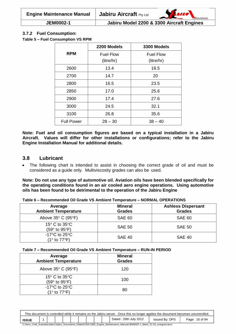
3.7.2 Fuel Consumption:
Table 5 – Fuel Consumption VS RPM
RPM
2200 Models 3300 Models
Fuel Flow
(litre/hr)
Fuel Flow
(litre/hr)
2600 13.4 18.5
2700 14.7 20
2800 16.5 23.5
2850 17.0 25.6
2900 17.4 27.6
3000 24.5 32.1
3100 26.8 35.6
Full Power 28 – 30 38 – 40
Note: Fuel and oil consumption figures are based on a typical installation in a Jabiru Aircraft. Values will differ for other installations or configurations; refer to the Jabiru Engine Installation Manual for additional details.
3.8 Lubricant
The following chart is intended to assist in choosing the correct grade of oil and must be considered as a guide only. Multiviscosity grades can also be used.
Note: Do not use any type of automotive oil. Aviation oils have been blended specifically for the operating conditions found in an air cooled aero engine operations. Using automotive oils has been found to be detrimental to the operation of the Jabiru Engine Table 6 – Recommended Oil Grade VS Ambient Temperature – NORMAL OPERATIONS
Average Ambient Temperature
Mineral Grades
Ashless Dispersant Grades
Above 35° C (95°F) SAE 60 SAE 60
15° C to 35°C (59° to 95°F)
SAE 50 SAE 50
-17°C to 25°C (1° to 77°F)
SAE 40 SAE 40
Table 7 – Recommended Oil Grade VS Ambient Temperature – RUN-IN PERIOD
Average Ambient Temperature
Mineral Grades
Above 35° C (95°F) 120
15° C to 35°C (59° to 95°F)
100
-17°C to 25°C (1° to 77°F)
80

Engine Maintenance Manual Jabiru Aircraft Pty Ltd
JEM0002-1 Jabiru Model 2200 & 3300 Aircraft Engines
This document is controlled while it remains on the Jabiru server. Once this no longer applies the document becomes uncontrolled.
ISSUE 1 Dated : 26th July 2012 Issued By: DPS Page: 17 of 94
C:\Aero_Craft_Australia\Jabiru\Jabiru_Documents_Edited\2200-3300_Engine_Maintenance_Manual\JEM0002-1_Maint_22-33_unsigned.docx
Table 8 – Oil SAE VS Commercial Designations
Equivalence of SAE and commonly used Commercial Grade designations:
SAE: 20 30 40 50 60
Commercial: 55 35 80 100 120
Figure 1 – Oil System Schematic
3.9 Cooling System
Type: Free air cooled. Pressure: The required pressure drop across the cylinders at 1.3 Vs (clean stall speed) is 4.3
cm (1.7") water gauge, minimum. A minimum of 6cm (2.4”) is recommended at cruise speed.
Note: Proper cooling is vital for engine operation. Values given are for a typical Jabiru Aircraft. Values will differ for other installations or configurations; refer to the Jabiru Engine Installation Manual for additional details.

Engine Maintenance Manual Jabiru Aircraft Pty Ltd
JEM0002-1 Jabiru Model 2200 & 3300 Aircraft Engines
This document is controlled while it remains on the Jabiru server. Once this no longer applies the document becomes uncontrolled.
ISSUE 1 Dated : 26th July 2012 Issued By: DPS Page: 18 of 94
C:\Aero_Craft_Australia\Jabiru\Jabiru_Documents_Edited\2200-3300_Engine_Maintenance_Manual\JEM0002-1_Maint_22-33_unsigned.docx
3.10 Operating Speeds and Limits
3.10.1 Ground Operating Limits
Table 9 – Ground Operating Limitations
All 2200 Variants All 3300 Variants Notes
Idle Speed 900 RPM 800-850 set while engine is hot
Oil Pressure – Idle Min: 80 kPa (11 psi)
Max: 525 kPa (76 psi) Min: 80 kPa (11 psi)
Max: 525 kPa (76 psi)
Oil Temperature Max. 100°C (212°F) Max. 100°C (212°F)
Max. CHT 180oC (356
oF) 180
oC (356
oF)
Note: If ground temperature limits are reached, shut the engine down or cool it by pointing the aircraft into wind.
3.10.2 In-Flight Operating Limits
Model: All 2200 Variants 3300L All Other 3300 Models
Maximum Speed 3300 RPM 3300 RPM 3300 RPM
Maximum Continuous Speed 3300 RPM 2850 RPM 3300 RPM
Oil Pressure – Normal Operations
Min 220 kPa (31 psi) Max 525 kPa (76 psi)
Min 220 kPa (31 psi) Max 525 kPa (76 psi)
– Idle Min 80 kPa (11 psi) Min 80 kPa (11 psi)
– Starting & Warm up Max 525 kPa (76 psi) Max 525 kPa (76 psi)
Oil Temperature: Min 15°C (59°F)
Max. 118 °C (244°F)
Min 15°C (59°F)
Max. 118°C (244°F)
Oil Continuous Temperature 80 - 100°C (176° - 212°F) 80 - 100°C (176° - 212°F)
Max. CHT (Climb) 200°C (392°F) 200°C (392°F)
Max Continuous CHT (Cruise)
180oC (356
oF) 180
oC (356
oF)
EGT (Mid-Range / Cruise) Min 680° - 720°C
(1256° - 1328°F) Min 680° - 720°C (1256° - 1328°F)
EGT (Above 70% Power) 640° - 680°C (1184° - 1256°F) 640° - 680°C (1184° - 1256°F)
Time with CHT at between 180°C and 200°C is not to exceed 5 Minutes
Time with engine speeds above 2850 RPM is not to exceed 10 minutes for 3300L models.
Read Cylinder Head Temperature – CHT – under the spark plug nearest to the exhaust on the hottest cylinder.
An EGT gauge is not included as standard equipment on the Jabiru engines, though a system can be supplied as an option.
Note: When testing an engine installation which differs from a typical Jabiru Aircraft installation (even if only by the type of propeller used), the use of EGT sensors on each cylinder is essential to ensure that all cylinders are receiving correct fuel/air mixture in all modes of operation.

Engine Maintenance Manual Jabiru Aircraft Pty Ltd
JEM0002-1 Jabiru Model 2200 & 3300 Aircraft Engines
This document is controlled while it remains on the Jabiru server. Once this no longer applies the document becomes uncontrolled.
ISSUE 1 Dated : 26th July 2012 Issued By: DPS Page: 19 of 94
C:\Aero_Craft_Australia\Jabiru\Jabiru_Documents_Edited\2200-3300_Engine_Maintenance_Manual\JEM0002-1_Maint_22-33_unsigned.docx
3.11 Torque Specifications Table 10 – Torque Specifications
Part Nom. Dia (mm) Torque
nm (ft.lbs)
Spark Plugs 12mm 11 (8)
Cylinder Head Bolts New installation: head screws are set at 24 lb.ft Subsequent checks are carried out at 20 lb.ft
5/16" 34 (24) 27 (20)
Flywheel/Gear Bolts 1/4" 5/16” 3/8”
20 (15) 34 (24) 40 (30)
Crankshaft Prop Flange Cap Screws (Lockwire – for std length flange only)
3/8" 40 (30)
Tappet Cover Cap Screws 1/4" 7 (5)
Starter Motor Bolts 1/4" 11 (8)
Carburettor Flange Bolts 1/4" 11 (8)
Alternator & Coil Mount Bolts 1/4" 14 (10)
Sump Plug 1/2" 11 (8)
1/8 NPT Plug – Lower Head Bolt Access Plug 1/8 NPT 7 (5)
Propeller Bolts (For wooden propellers manufactured by Jabiru Aircraft only)
1/4" 8 - 9.5 (6 - 7)
3.12 Propeller Selection & Specifications
WARNING: Correct propeller selection, tuning and maintenance are vital for the safe operation of this engine. The guidance given herein and in the Engine Installation Manual must be adhered
to for safe operation.
Many propeller brands and models are not approved by Jabiru Aircraft. In certain categories operators may choose to use these propellers, however they do so at their own risk. For information on which propellers are approved, please contact Jabiru P/L or our local representative.
Propeller selection is discussed in detail in the Jabiru Engine Installation Manual.
2-bladed, fixed-pitch wooden propellers manufactured by reputable companies are recommended by Jabiru Aircraft.
All propellers must be maintained in accordance to the propeller manufacturer’s requirements in conjunction with Jabiru Aircraft P/L requirements.
A maximum moment of inertia of 0.25 kgm2 is recommended for the propeller assembly for 2200 engine variants.
A maximum moment of inertia of 0.30 kgm2 is recommended for the propeller assembly for 3300 engine variants.

Engine Maintenance Manual Jabiru Aircraft Pty Ltd
JEM0002-1 Jabiru Model 2200 & 3300 Aircraft Engines
This document is controlled while it remains on the Jabiru server. Once this no longer applies the document becomes uncontrolled.
ISSUE 1 Dated : 26th July 2012 Issued By: DPS Page: 20 of 94
C:\Aero_Craft_Australia\Jabiru\Jabiru_Documents_Edited\2200-3300_Engine_Maintenance_Manual\JEM0002-1_Maint_22-33_unsigned.docx
3.13 Electrical System Specifications Table 11 – Ignition System
Honda Coil Jabiru Coil
Primary Resistance 0.8 Ω to 1.0 Ω 1.7 Ω to 1.8 Ω
Secondary Resistance 5.9k Ω to 7.1k Ω 18k Ω to 30k Ω
Ignition Harness Resistance 6.7kR per 300mm of length
6.7kR per 300mm of length
Table 12 - Alternator
Coil Resistance 0.4 to 1.1 Ω at 20oC
Coil Earth Resistance Infinite
Maximum RPM drop when running on 1 ignition: 100 RPM
Engine Maintenance Manual Jabiru Aircraft Pty Ltd
JEM0002-1 Jabiru Model 2200 & 3300 Aircraft Engines
This document is controlled while it remains on the Jabiru server. Once this no longer applies the document becomes uncontrolled.
ISSUE 1 Dated : 26th July 2012 Issued By: DPS Page: 21 of 94
C:\Aero_Craft_Australia\Jabiru\Jabiru_Documents_Edited\2200-3300_Engine_Maintenance_Manual\JEM0002-1_Maint_22-33_unsigned.docx
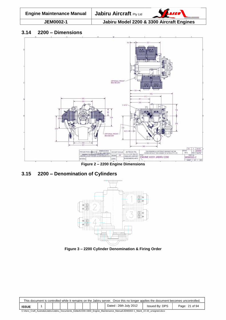
3.14 2200 – Dimensions
Figure 2 – 2200 Engine Dimensions
3.15 2200 – Denomination of Cylinders
Figure 3 – 2200 Cylinder Denomination & Firing Order

Engine Maintenance Manual Jabiru Aircraft Pty Ltd
JEM0002-1 Jabiru Model 2200 & 3300 Aircraft Engines
This document is controlled while it remains on the Jabiru server. Once this no longer applies the document becomes uncontrolled.
ISSUE 1 Dated : 26th July 2012 Issued By: DPS Page: 22 of 94
C:\Aero_Craft_Australia\Jabiru\Jabiru_Documents_Edited\2200-3300_Engine_Maintenance_Manual\JEM0002-1_Maint_22-33_unsigned.docx
3.16 3300 – Dimensions
Figure 4 – 3300 Engine Dimensions
3.17 3300 – Denomination of Cylinders
Figure 5 – 3300 Cylinder Denomination & Firing Order

Engine Maintenance Manual Jabiru Aircraft Pty Ltd
JEM0002-1 Jabiru Model 2200 & 3300 Aircraft Engines
This document is controlled while it remains on the Jabiru server. Once this no longer applies the document becomes uncontrolled.
ISSUE 1 Dated : 26th July 2012 Issued By: DPS Page: 23 of 94
C:\Aero_Craft_Australia\Jabiru\Jabiru_Documents_Edited\2200-3300_Engine_Maintenance_Manual\JEM0002-1_Maint_22-33_unsigned.docx
3.18 Distributor Cylinder Map
Figure 6 – Distributor Cylinder Map
3.19 2200 – Power Curve
Multiply Kilowatts (kW) by 1.341 to get Horsepower (hp). i.e. 63.5 kW x 1.341 = 85 hp.
Figure 7 – Power / Torque Curve – Typical 2200A Engine
POWER CURVE
20.0
25.0
30.0
35.0
40.0
45.0
50.0
55.0
60.0
65.0
70.0
1500 1700 1900 2100 2300 2500 2700 2900 3100 3300
RPM
kW
50
100
150
200
250
300
350
400
450
Nm POWER
TORQUE

Engine Maintenance Manual Jabiru Aircraft Pty Ltd
JEM0002-1 Jabiru Model 2200 & 3300 Aircraft Engines
This document is controlled while it remains on the Jabiru server. Once this no longer applies the document becomes uncontrolled.
ISSUE 1 Dated : 26th July 2012 Issued By: DPS Page: 24 of 94
C:\Aero_Craft_Australia\Jabiru\Jabiru_Documents_Edited\2200-3300_Engine_Maintenance_Manual\JEM0002-1_Maint_22-33_unsigned.docx
Figure 8 – Power Curve - Typical 2200C, 2200B, Engine
3.20 3300 – Power Curve
Figure 9 – Power / Torque Curves – Typical 3300 Engine
4 CYLINDER POWER CURVE
20.0
25.0
30.0
35.0
40.0
45.0
50.0
55.0
60.0
65.0
1500 1700 1900 2100 2300 2500 2700 2900 3100 3300
RPM
kW
50
100
150
200
250
300
350
400
450
Nm
POWER
TORQUE
6 CYLINDER POWER CURVE
20
30
40
50
60
70
80
90
100
1500 1700 1900 2100 2300 2500 2700 2900 3100 3300 3500
RPM
kW
50
100
150
200
250
300
350
400
450
Nm
POWER
TORQUE

Engine Maintenance Manual Jabiru Aircraft Pty Ltd
JEM0002-1 Jabiru Model 2200 & 3300 Aircraft Engines
This document is controlled while it remains on the Jabiru server. Once this no longer applies the document becomes uncontrolled.
ISSUE 1 Dated : 26th July 2012 Issued By: DPS Page: 25 of 94
C:\Aero_Craft_Australia\Jabiru\Jabiru_Documents_Edited\2200-3300_Engine_Maintenance_Manual\JEM0002-1_Maint_22-33_unsigned.docx
4 OPERATING INSTRUCTIONS To ensure that the engine operates reliably, carefully observe all of the operating &
maintenance instructions.
4.1 Daily Checks
Note: The checks given below are the basic requirements for safe operation of the engine. Any additional inspections required by the aircraft operating instructions (such as the Pilot Operating Handbook) must also be carried out.
Ensure free movement of throttle, choke & carburetor heat cables. Return throttle to idle before attempting to start engine.
Check Oil Level, replenish if necessary. i) Check oil level by screwing in cap fully before withdrawing ii) Oil level should be between the MAX & MIN marks - but must never be below the
bottom of the dipstick. iii) Before long periods of operation, ensure that the level is at least at the mid position. iv) Difference in the oil quantity between MAX & MIN mark is 300 mL (0.317 US Quarts).
Note: overfilling is detrimental to the engine; it will usually result in elevated engine temperatures and rapid oil use.
v) Also see Section 4.10 for special operating procedures for the first 25 hours of operation or after an overhaul.
Check lubrication & fuel system for leaks. i) Visually inspect for signs of leakage on the ground where the aircraft was parked
overnight ii) Inspect the oil cooler for leaks through the cowl opening iii) Visually inspect the underside of the aircraft for fresh oil or fuel residue.
Check exhaust system for security. i) Wriggle the exhaust tail pipes by hand, checking for excessive movement, rubbing on
cowls or unusual noises.
With Ignition & Master OFF, and throttle closed, turn propeller by hand & observe engine for odd noises or heavy movements. Check for regular compression. If irregular, refer to Trouble Shooting section of this Manual for corrective action.
CAUTION:
Prior to pulling through the propeller by hand, both ignition circuits & the Master Switch must be switched OFF, the brakes applied and the throttle closed.
A common cause of low compression is poorly sealing valves. Continued operation in this condition will result in damage to valves, valve seats, valve guides & overhead gear.
WARNING
A hot engine may fire even with the ignition/s switched OFF. DO NOT TURN OVER A HOT ENGINE BY HAND
4.2 Starting Procedure
Activate Starter for a maximum of 20 seconds, followed by a cooling period of 1 minute.
When engine runs, adjust the throttle to achieve smooth running at approximately 1200 RPM. Deactivate Choke. Check Oil Pressure has risen within 5 seconds - if not, shut down.
Note: After an oil change, crank the engine to obtain oil pressure before starting.

Engine Maintenance Manual Jabiru Aircraft Pty Ltd
JEM0002-1 Jabiru Model 2200 & 3300 Aircraft Engines
This document is controlled while it remains on the Jabiru server. Once this no longer applies the document becomes uncontrolled.
ISSUE 1 Dated : 26th July 2012 Issued By: DPS Page: 26 of 94
C:\Aero_Craft_Australia\Jabiru\Jabiru_Documents_Edited\2200-3300_Engine_Maintenance_Manual\JEM0002-1_Maint_22-33_unsigned.docx
4.2.1 Cold Engine
Fuel Tap OPEN Choke ON – HOLD (in cold conditions less than 20°C) Fuel Pump ON for 10 seconds then off Throttle FULLY CLOSED: “cracked” throttle degrades choke Master ON Ignition BOTH ON Starter PRESS
4.2.2 Warm Engine
As for cold start, with the following differences: Choke OFF Throttle Slightly “Cracked” from off position (approx 2%).
4.3 Warming Up Period
Start the warming up period with the engine running at 1200 RPM for around 1 minute.
Continue at 2000 RPM depending on ambient temperature, until oil temperature reaches 15°C (59°F).
Check the two ignition circuits at 2000 RPM Note: Engine RPM should not drop by more than 100 RPM when 1 ignition is turned OFF.
WARNING
DO NOT apply full power until CHT reaches 100 °C (212°F) DO NOT apply full power until Oil Temperature reaches 50°C (104°F)
DO NOT allow cylinder heads to rise above 180°C (356°F) during ground running.
4.4 Ground Running
When running the engine on the ground before flight use minimum power settings and minimum time to avoid overheating: the engine is already run-in and further ground running can be detrimental.
Avoid prolonged ground running at elevated RPM as the engine can easily be over heated during ground operations – remember air ducts are designed for in flight cooling.
Ground running at high power settings for more than a few minutes requires the use of special, oversize air ducts and oil cooler.
WARNING Prolonged running at full power on the ground can cause engine overheating & damage
unless special, oversized air ducts and oil coolers are used.
4.5 Take-Off
Ensure all temperatures and pressures are within limitations before applying take-off power.
Climb with the engine at maximum continuous power.
Observe Oil & Cylinder Head Temperatures & Oil Pressure.
Max RPM at Full Throttle is 3300 RPM WARNING
Limits must not be exceeded!
4.6 Engine Stop
In normal conditions the engine will cool enough during descent & taxiing to permit it to be stopped by switching OFF the ignitions.

Engine Maintenance Manual Jabiru Aircraft Pty Ltd
JEM0002-1 Jabiru Model 2200 & 3300 Aircraft Engines
This document is controlled while it remains on the Jabiru server. Once this no longer applies the document becomes uncontrolled.
ISSUE 1 Dated : 26th July 2012 Issued By: DPS Page: 27 of 94
C:\Aero_Craft_Australia\Jabiru\Jabiru_Documents_Edited\2200-3300_Engine_Maintenance_Manual\JEM0002-1_Maint_22-33_unsigned.docx
4.7 Engine Stop and Start During Flight
Reduce power to 2000 RPM to cool engine for 30 seconds, then to idle.
Switch ignitions OFF. At higher speeds (above 90 KIAS) the propeller may windmill – reduce aircraft speed until propeller stops turning.
Starting procedure is the same as ground starting: without choke for a warm engine & with choke for a cold engine. As the engine cools quickly when stopped in flight the choke will normally be needed to restart.
WARNING DO NOT apply the starter motor if the propeller is windmilling.
4.8 Operation in Winter
It is recommended to carry out an engine service prior to the start of the cold season. For selection of oil to suit colder weather consult the table of lubricants given in the Engine Specifications above.
Refer to Section 9.15 for the Troubleshooting Cold Start Checklist if the engine becomes difficult to start.
4.9 Carburettor Icing
It is important to distinguish between two kinds of icing: i) Icing due to water in fuel, and ii) Icing due to high air humidity.
4.9.1 Icing Due to Water in fuel
Water in fuel will accumulate at the lower parts of the fuel system & can lead to freezing of fuel lines, filters or jets. Remedies are: a) Drain, using fuel tank water drain. b) Ensure fuelling without traces of water. If in doubt, use a chamois as a filter. c) Install a generously sized water separator. d) Ensure that fuel lines do not permit the accumulation of water. e) Prevent condensation of humidity, i.e. avoid temperature differences between the aircraft &
fuel. CAUTION:
Do not add any form of alcohol (including automotive fuels with Ethanol or similar additives) to a Jabiru Aircraft fiberglass fuel tank unless directed otherwise by the aircraft operating manual. The sealant used in some (older) tanks will be damaged if it comes into
contact with alcohol, leading to leaks.
4.9.2 Icing Due to High Air Humidity.
Carburettor icing due to humidity may occur in the carburettor venturi & leads to performance loss due to changes in the mixture.
The only effective remedy is to preheat the intake air by use of the Carburettor Heat Control.
4.10 New Engine Operation
This engine has been ground run to a specific run in program and is ready for flight when delivered.
Before initial start add oil to engine (2.3 litres with cooler for 2200 engine, 3.5L with cooler for 3300 engine).
The engine has been INHIBITED before dispatch from the factory. It is recommended that this is removed before the first engine start: remove 1 spark plug from each cylinder and apply the starter motor for around 10 seconds: inhibitor oil will be ejected from the cylinders. Re-fit spark plugs & re-assemble engine.

Engine Maintenance Manual Jabiru Aircraft Pty Ltd
JEM0002-1 Jabiru Model 2200 & 3300 Aircraft Engines
This document is controlled while it remains on the Jabiru server. Once this no longer applies the document becomes uncontrolled.
ISSUE 1 Dated : 26th July 2012 Issued By: DPS Page: 28 of 94
C:\Aero_Craft_Australia\Jabiru\Jabiru_Documents_Edited\2200-3300_Engine_Maintenance_Manual\JEM0002-1_Maint_22-33_unsigned.docx
Remove ALL plastic bungs on engine before starting. Bungs are fitted to the exhaust, carburettor, crankcase oil vent and fuel pump.
The engine idle speed cannot be set accurately at the factory as the engine is run on a Dynamometer only. Therefore it is necessary to adjust the throttle idle stop(s) to obtain the appropriate RPM (Section 3.10.1) when engine is warm before first flight. Note that as the engine run-in process progresses idle speed will gradually increase so initial idle should be set low – within practical limits
WARNING Ensure engine does not stall when throttle is set to idle. While cold, test by pulling BOTH
throttle levers against the idle stop.
VARY your RPM when flying with a new engine.
Do not “Baby” a new engine. The purpose of breaking in an engine correctly is to ensure a long reliable life. All moving parts need freeing up especially piston rings to cylinder walls. This is best accomplished when the greatest B.M.E.P. (Break Mean Effective Pressure) occurs. That is at 75% power and above. Early running of an engine should include periods at high RPM and power settings.
Failure to operate at realistic power settings could be detrimental to engine condition & long-term performance.
Always take off using full power – especially when the engine is new.
Avoid heat build up – monitor CHT and oil temps. Note that Initial temps will be elevated due to the friction of a new engine. Careful monitoring by the pilot is needed during this initial period to ensure long life of the engine and its components.
CIRCUIT WORK is a good sequence for initial run in work. i) Abbreviate circuits initially ii) Step climbs, climb at shallow angles & higher airspeeds to reduce engine temperatures iii) Do not carry out glide approaches iv) Gradually reduce power v) Avoid sudden heating up and sudden cooling down
Wherever practical, climb at a higher airspeed to assist engine cooling. For example, an aircraft with a best climb speed of 65 knots can often be climbed at around 80-85 knots with minimum impact on climb rate – although this varies depending on the airframe. At the higher speed setting the engine has much more cooling air available and revs higher. These conditions provide the engine with a significantly improved environment and generally both improve performance and reduce temperatures.
Note that all engine temperatures can be expected to drop noticeably when the new engine run-in oil is replaced with standard oil.
4.11 Engine Installation
Air cooled engines require careful design and tuning of the installation in order to operate at their best.
Ensure that installations are designed in consultation with the Jabiru Engine Installation Manual and that all installation targets (for cooling, EGT, RPM etc) are met.
WARNING
Improper installation can cause severe engine damage and engine stoppage. It is the Operator’s responsibility to ensure that all installation targets are met. Damage to engines caused by installation issues may not be covered by Jabiru’s Limited, Express Warranty.

Engine Maintenance Manual Jabiru Aircraft Pty Ltd
JEM0002-1 Jabiru Model 2200 & 3300 Aircraft Engines
This document is controlled while it remains on the Jabiru server. Once this no longer applies the document becomes uncontrolled.
ISSUE 1 Dated : 26th July 2012 Issued By: DPS Page: 29 of 94
C:\Aero_Craft_Australia\Jabiru\Jabiru_Documents_Edited\2200-3300_Engine_Maintenance_Manual\JEM0002-1_Maint_22-33_unsigned.docx
5 Maintainer Requirements The following are recommended as the minimum requirements for someone carrying out
maintenance & inspection on Jabiru Engines.
5.1 Facilities
An enclosed workspace with a sealed (i.e. not dirt) floor, adequate lighting, provision of compressed air & mains electricity.
5.2 Training
Completion of an approved instruction course specific to Jabiru Engines. Approved courses include those offered by Jabiru Aircraft Australia or by local Jabiru Aircraft representatives.
5.3 Rating
Commercial maintainers must hold suitable ratings as required by their local Airworthiness Authority.
5.4 Experience
A minimum of 1 years experience working on Jabiru Engines under supervision is recommended for commercial maintainers before working un-supervised.
5.5 Tool & Gauge Control
Tool and gauge control is an important part of aviation maintenance systems. Tools and gauges must be accurate enough for the intended use (i.e. a 12” steel ruler is not the appropriate tool to use to measure the cylinder bore diameter) and be accurately calibrated – for example by an approved laboratory.
Calibrations must be kept up to date. This means a check calibration every year or more frequently for regularly used, critical tooling.
Even quality equipment will wear over time so items like reams, go / no-go gauges and valve seat cutting tools must periodically be checked to ensure they remain within limits.
5.6 Tools:
Access to the following tools will be required. All tools must be good quality items:
Allen keys: 1/4”, 5/32” 3/16” and 3/16” ball end in regular 3/8” drive and “T” handle
Circlip pliers (internal)
Crowsfoot: 2” in regular 3/8” drive: 7/16”
Hydraulic lifter tool (hydraulic lifter engines only)
Pliers: long nose, regular square jaw, side cutters
Ring/open end spanners: 5/16”, 3/8”, 7/16”, 1/2”, 9/16”, 10mm, 17mm
Ratchet 3/8” drive, breaker bar, 2” extension bar, 3/8”, 7/16”, 1/2” sockets, 7/16” tube socket, 18mm spark plug socket
Screwdrivers: flat blade and Phillips head in various sizes
Feeler gauges: metric and imperial sizes
Torque wrench: 3/8” drive, “name” brand (Snap-On, Warren & Brown etc), recently calibrated

Engine Maintenance Manual Jabiru Aircraft Pty Ltd
JEM0002-1 Jabiru Model 2200 & 3300 Aircraft Engines
This document is controlled while it remains on the Jabiru server. Once this no longer applies the document becomes uncontrolled.
ISSUE 1 Dated : 26th July 2012 Issued By: DPS Page: 30 of 94
C:\Aero_Craft_Australia\Jabiru\Jabiru_Documents_Edited\2200-3300_Engine_Maintenance_Manual\JEM0002-1_Maint_22-33_unsigned.docx
5.7 Equipment:
Access to the following equipment will be required:
Bench vice with padded jaws
Calipers: must read up to 180mm
Degreasing/cleaning system with solvent/solution containment/recycling
Dial indicator and magnetic stand, vee blocks
Hand press
Heat gun or small butane/propane torch with a soft pencil flame
Micrometer and internal measuring tools, must read up to 100mm
Multimeter or an ohmmeter
Spring scale: must read up to 2.5kg in 0.1kg increments
Thread taps: 1/4", 5/16”, 3/8” UNF and UNC
Valve seat cutters: 30°, 45° and 60°
Valve spring compressor, motorcycle type or a ‘G’ clamp with a machined spring cup
5.8 General:
Brass drifts, punches, rags, soft mallet, hammers
Greases: molybdenum disulphide, general purpose
Loctite compounds: 242/243/262 ThreadLocker, 515 Sealant, 620 Retainer, 7471 Cure Accelerator
Lubricants: engine oil, Nulon L90
TorqueSeal brand security marking lacquer or similar, such as coloured nail varnish

Engine Maintenance Manual Jabiru Aircraft Pty Ltd
JEM0002-1 Jabiru Model 2200 & 3300 Aircraft Engines
This document is controlled while it remains on the Jabiru server. Once this no longer applies the document becomes uncontrolled.
ISSUE 1 Dated : 26th July 2012 Issued By: DPS Page: 31 of 94
C:\Aero_Craft_Australia\Jabiru\Jabiru_Documents_Edited\2200-3300_Engine_Maintenance_Manual\JEM0002-1_Maint_22-33_unsigned.docx
5.9 Sealants and Compounds
Figure 10 – Sealants, Compounds & Lubricants #1
Greaseless Lubricant – used for cleaning, fitting rubber hoses, general purpose light lubricant which leaves no residue. Can be used for corrosion protection on steel parts in storage.
Loctite 7471 Cure Accelerator - Loctite 7471 is used where increased cure speed of Loctite anaerobic products is required. 7471 is particularly recommended when prevailing temperature is low (<15 °C). Used as a surface prep when very high quality fitting of screws is required.
Nulon Extreme Pressure Anti-Seize Lubricant (L90) offers extremely high film strength and adhesion to protect moving parts against friction, wear and seizure in all types of extreme conditions. Used to lubricate parts during assembly, initial start and running.
Figure 11 – Sealants, Compounds & Lubricants #2
Loctite 587 Blue, High Performance RTV Silicone Gasket Maker is a one part RTV silicone that forms tough, flexible gaskets directly on the flange. Offers excellent adhesion to oily surfaces. Resistant to most chemicals and solvents. Fills gaps to 0.25".

Engine Maintenance Manual Jabiru Aircraft Pty Ltd
JEM0002-1 Jabiru Model 2200 & 3300 Aircraft Engines
This document is controlled while it remains on the Jabiru server. Once this no longer applies the document becomes uncontrolled.
ISSUE 1 Dated : 26th July 2012 Issued By: DPS Page: 32 of 94
C:\Aero_Craft_Australia\Jabiru\Jabiru_Documents_Edited\2200-3300_Engine_Maintenance_Manual\JEM0002-1_Maint_22-33_unsigned.docx
Loctite RTV Silicone 5920 is a premium silicone. Superior adhesion and oil resistance. Temperature range -75 °F to 700 °F intermittent; resists auto and shop fluids and vibration
Loctite Gasket Maker 515 Flange Sealant is a flexible, gasketing material for use on rigid machined flanges with less than 0.015"gap.
Loctite 577 is designed for the locking and sealing of metal threaded pipes and fittings. Used to seal fuel, oil and brake fittings.
Loctite Gasket Sealant #2 is a black, reliable, paste-like gasket sealant, dressing, and coating. Sets more slowly to a pliable film best suited for non-rigid, vibrating assemblies. Used on the induction manifold.
Bearing Blue – a high colour marking aid which spreads very easily, does not clog or dry out.
Figure 12 – Sealants, Compounds & Lubricants #4
Loctite Graphite-50 Anti-Seize is a thread lubricant. It is a non-metallic lubricant; but shows good electrical conductivity in metal-to-metal joints. Use on machine threads, tapered pipe threads, for press-fit and slip-fit joints. This product is typically used in applications with an operating range of -29 °C to +482 °C. Used on spark plugs and cylinder head screws.
Loctite Nickel Anti-Seize is copper free. Recommended for stainless steel and other metal fittings. For preventing corrosion, seizing, and galling in harsh, chemical environments, and temperatures to 2400 °F (1315 °C). Used on cylinder head screws.
Figure 13 – Sealants, Compounds & Lubricants #4
Loctite Gasket Maker 515 Flange Sealant is a flexible, gasketing material for use on rigid machined flanges with less than 0.015"gap.
Rubber grease – used to initially fill seals and lubricate rubber parts on assembly – though Nulon L90 is preferred and generally more effective.
High-temp grease – used to give initial start-up lubrication to many parts of the engine, including the oil seals.
“Cam Honey” (Molybdenum Disulphide) for cam journals and lobes.

Engine Maintenance Manual Jabiru Aircraft Pty Ltd
JEM0002-1 Jabiru Model 2200 & 3300 Aircraft Engines
This document is controlled while it remains on the Jabiru server. Once this no longer applies the document becomes uncontrolled.
ISSUE 1 Dated : 26th July 2012 Issued By: DPS Page: 33 of 94
C:\Aero_Craft_Australia\Jabiru\Jabiru_Documents_Edited\2200-3300_Engine_Maintenance_Manual\JEM0002-1_Maint_22-33_unsigned.docx
5.10 Loctite 620 & Other Retaining Compounds
Figure 14 – Sealants, Compounds & Lubricants #3
Loctite 620 is designed for the bonding of cylindrical fitting parts. Typical applications include locating pins in radiator assemblies, sleeves into pump housings and bearings in auto transmissions. Particularly suitable for applications where temperature resistance up to 200°C is required. Used as a ultra-strong threadlock. Loctite 620 is specified in several places in Jabiru Engine assembly where a reliable bond is essential. When using it, follow the rules below:
WARNING Failure to use Loctite 620 correctly can result in engine failure
- Check use-by dates. Loctite 620 (like most other compounds used on the engine for sealing etc) has a use-by date. Generally this is not printed on the bottle but can be found by contacting the distributor and telling them the batch number.
- Work fast. Loctite 620 can cure very quickly. All screws must be torqued to final settings as quickly as practical. Anything more than a minute is not recommended, particularly if cure accelerator spray (Loctite 7471) is used.
- Only use as much as required/specified. Excess compound can make it nearly impossible to disassemble the parts later.
- Surface preparation is critical. Threads must be cleaned and prepared properly. - To Remove. Can normally be achieved by heating the screw to over 150°C using a pencil-
point gas burner. Minimise direct heat applied to the head of the screw as this can weaken the drive socket – direct heat towards the thread as must as possible.
Loctite 290 is designed for the locking and sealing of threaded fasteners. Because of its low viscosity and capillary action, the product wicks between engaged threads and eliminates the need to disassemble prior to application. The product cures when confined in the absence of air between close fitting metal surfaces and prevents loosening and leakage from shock and vibration. The product can also fill porosity in welds, castings and powdered metal parts.
Loctite 262 is designed for the permanent locking and sealing of threaded fasteners. Typical applications include the locking and sealing of large bolts and studs (up to M25 ). A medium strength threadlock.
Loctite 243 is designed for the locking and sealing of threaded fasteners which require normal disassembly with standard hand tools. Particularly suitable for applications on less active substrates such as stainless steel and plated surfaces, where disassembly with hand tools is required for servicing. A medium-strong threadlock. Typically used for cap screws into castings or Aluminium.

Engine Maintenance Manual Jabiru Aircraft Pty Ltd
JEM0002-1 Jabiru Model 2200 & 3300 Aircraft Engines
This document is controlled while it remains on the Jabiru server. Once this no longer applies the document becomes uncontrolled.
ISSUE 1 Dated : 26th July 2012 Issued By: DPS Page: 34 of 94
C:\Aero_Craft_Australia\Jabiru\Jabiru_Documents_Edited\2200-3300_Engine_Maintenance_Manual\JEM0002-1_Maint_22-33_unsigned.docx
5.11 Special Tools
Special tools can simplify maintenance and are shown in the photos below.
Note that only those tools applicable to normal maintenance are shown below: refer to the Jabiru Engine Overhaul Manual for additional tools required to carry out overhauls.
Figure 15 – Valve Compressor / Lifter Bleed Tools
Figure 16 – Dimensional Details For Lifter Tool
Used to compress the valve springs, allowing the rocker shaft to be removed and the hydraulic valve lifters to be bled.
Figure 17 – Valve Leakage Vacuum Tester
Connected to an air compressor generates a vacuum which is applied to the valve (while closed) to check for a poorly-sealing valve / seat.

Engine Maintenance Manual Jabiru Aircraft Pty Ltd
JEM0002-1 Jabiru Model 2200 & 3300 Aircraft Engines
This document is controlled while it remains on the Jabiru server. Once this no longer applies the document becomes uncontrolled.
ISSUE 1 Dated : 26th July 2012 Issued By: DPS Page: 35 of 94
C:\Aero_Craft_Australia\Jabiru\Jabiru_Documents_Edited\2200-3300_Engine_Maintenance_Manual\JEM0002-1_Maint_22-33_unsigned.docx
Figure 18 – Valve Spring Compressor / Collet Remover
Modified sash clamp shown (commercial types are also available). Used to compress the valve spring to allow the collets to be removed from the valve and then the valve to be removed from the head. Also used for installation.
Figure 19 – Leak Down Tester
Figure 20 – Hand Press & Inserts
A hand press is used to install rocker bushes, distributor shaft and crankshaft seals. Inserts are made for the press to suit the parts.
Figure 21 – Optical Tachometer
An adaptor is made by welding a compressor air fitting to the base of an old spark plug. The adaptor is screwed into the spark plug hole of a head and connected to the leak-down tester to check the condition of the cylinder assembly.
An accurate optical tachometer. Reads directly from reflective strips fitted to the propeller and is used whenever an accurate check of RPM is required. Will usually read propeller RPM in sunlight without reflective strips.

Engine Maintenance Manual Jabiru Aircraft Pty Ltd
JEM0002-1 Jabiru Model 2200 & 3300 Aircraft Engines
This document is controlled while it remains on the Jabiru server. Once this no longer applies the document becomes uncontrolled.
ISSUE 1 Dated : 26th July 2012 Issued By: DPS Page: 36 of 94
C:\Aero_Craft_Australia\Jabiru\Jabiru_Documents_Edited\2200-3300_Engine_Maintenance_Manual\JEM0002-1_Maint_22-33_unsigned.docx
Figure 22 – Supplementary Oil Pressure Gauge
Figure 23 – “Finger Bar”
A long lever arm fitted with pins that pit into the propeller flange holes. Allows the crank to be held easily while tightening or loosening propeller flange or flywheel screws.
Figure 24 – Carburettor Needle Seat Remover and Installer
Used during initial engine proof runs and / or running-in. Used as a more accurate gauge to confirm the readings of the standard aircraft oil pressure gauge. Fitting uses 1/8 NPT thread.
The tap (at bottom) is used to cut a thread into the needle seat (small part, middle-left). The slide hammer (at top) screws into this thread and is used to draw the needle seat out of the carburettor. The nylon driver (in centre) is used to fit the new needle seat to the carburettor body.

Engine Maintenance Manual Jabiru Aircraft Pty Ltd
JEM0002-1 Jabiru Model 2200 & 3300 Aircraft Engines
This document is controlled while it remains on the Jabiru server. Once this no longer applies the document becomes uncontrolled.
ISSUE 1 Dated : 26th July 2012 Issued By: DPS Page: 37 of 94
C:\Aero_Craft_Australia\Jabiru\Jabiru_Documents_Edited\2200-3300_Engine_Maintenance_Manual\JEM0002-1_Maint_22-33_unsigned.docx
Figure 25 – “Crowsfoot” Adaptor
Figure 26 – Universal Joint tool FU14B
Figure 27 – Safety Wire / Wire Pliers
Wire used to secure items (nuts, bolts etc) to prevent rotation in service.
5.12 Torque / Tension Wrench
Figure 28 – Torque Wrench & Crowsfoot Adaptor Setting 1
Commercially available tool designed for high-torque applications on small nuts.
L1 L2
Snap-On tool FU14B – a universal joint with inbuilt 7/16” nut drive. Used for changing through-bolt nuts without removing cylinder heads.

Engine Maintenance Manual Jabiru Aircraft Pty Ltd
JEM0002-1 Jabiru Model 2200 & 3300 Aircraft Engines
This document is controlled while it remains on the Jabiru server. Once this no longer applies the document becomes uncontrolled.
ISSUE 1 Dated : 26th July 2012 Issued By: DPS Page: 38 of 94
C:\Aero_Craft_Australia\Jabiru\Jabiru_Documents_Edited\2200-3300_Engine_Maintenance_Manual\JEM0002-1_Maint_22-33_unsigned.docx
Figure 29 – Torque Wrench & Crowsfoot Adaptor Setting 2
A good torque wrench is an essential tool for maintaining and overhauling Jabiru Engines. It’s important to realise however that even the best wrench needs calibrating occasionally. This can be done using a dead weight on the end of a known arm or – preferably – sending the wrench away to be calibrated. Note that Civil Aviation Authorities generally require that the tool be calibrated in a way which is traceable to a NATA-standard laboratory.
A “Crowsfoot” extension as shown in Figure 25 is also necessary – it allows high torque settings to be used on small nuts without damaging them. The crankcase through bolt nuts used on Jabiru engines are a good example of an application suitable for a crowsfoot extension. However, when using the extension as shown in Figure 28 the extra length will throw off the torque setting of the wrench. This must be corrected using the following formula:
.
L1 is the distance from the middle of the grip of the handle to the centre of the wrench drive lug
L2 is the distance in the direction of the handle from the centre of the wrench drive lug to the centre of the nut socket of the adaptor.
For example: a nut needs to be tensioned to 30lb.ft. The torque wrench is 12” long and the crowsfoot extension is 2” long. The extension is oriented as shown in Figure 28. This means that the torque wrench must be set to:
If the extension is oriented at 90° to the wrench as shown in Figure 29 then no correction is needed because L2 is zero.
Figure 30 – Using A Crowsfoot Adaptor
L1
L2 = 0
Corrected Torque Setting Required No Correction Required.

Engine Maintenance Manual Jabiru Aircraft Pty Ltd
JEM0002-1 Jabiru Model 2200 & 3300 Aircraft Engines
This document is controlled while it remains on the Jabiru server. Once this no longer applies the document becomes uncontrolled.
ISSUE 1 Dated : 26th July 2012 Issued By: DPS Page: 39 of 94
C:\Aero_Craft_Australia\Jabiru\Jabiru_Documents_Edited\2200-3300_Engine_Maintenance_Manual\JEM0002-1_Maint_22-33_unsigned.docx
5.13 Torque Application Procedure
Good torque application technique is essential if an accurate bolt torque reading is going to be obtained.
Firstly the nut must be tightened smoothly. Any jerks or bumps can cause the torque reading to be obtained prematurely.
The torque must be obtained while the nut is turning. If you stop to reposition the torque wrench and then the required torque reading is obtained without the nut turning, the nut needs to be loosened a little and then tightened again so the torque reading is obtained while turning.
Unless specified otherwise all torque settings given in this manual are “dry” – i.e. no special lubricant is applied to the threads or parts. Where directed otherwise it is vital that the directions are followed exactly.

Engine Maintenance Manual Jabiru Aircraft Pty Ltd
JEM0002-1 Jabiru Model 2200 & 3300 Aircraft Engines
This document is controlled while it remains on the Jabiru server. Once this no longer applies the document becomes uncontrolled.
ISSUE 1 Dated : 26th July 2012 Issued By: DPS Page: 40 of 94
C:\Aero_Craft_Australia\Jabiru\Jabiru_Documents_Edited\2200-3300_Engine_Maintenance_Manual\JEM0002-1_Maint_22-33_unsigned.docx
6 STORAGE & CLEANING
6.1 Parking
Whenever the engine is not active or being maintained it is strongly recommended that the following points are covered to prevent contamination and pest ingress: - Engine air inlet - Exhaust outlet
If the engine is not fitted in an airframe then the following must also be sealed: - Inlets to carburettor and fuel pump - Engine crankcase vent - Pipe fittings of oil cooler adaptor (if oil cooler is not currently connected).
CAUTION Equip all covers with tags or other high-visibility devices to minimise the chance of
inadvertent operation with covers still fitted.
6.2 STORAGE
The following procedures assume that the engine is installed in a Jabiru airframe. For other aircraft types, refer to the manufacturer's service manual. If the engine is not fitted to an airframe, ignore those items referring to the airframe.
Note: Failure to store the engine for a long period of time, in excess of 90 days, without taking the preventative measures as outlined in the manual will affect claims upon Jabiru’s Limited, Express Warranty.
6.2.1 Flyable Storage
Flyable storage is defined as a maximum of 30 days non-operational storage.
Ensure that the engine has been stopped by turning off the fuel valve, thereby not leaving any fuel in the carburettor bowl.
Every 7th day the propeller should be rotated through 5 revolutions, without running the engine. Leave the propeller in the horizontal position to ensure even distribution of liquids in the wood. If left in the vertical position, liquids will drain to the lower tip resulting in an unbalanced propeller.
CAUTION Ensure that the Master and Ignition Switches are OFF before turning motor!
WARNING Do not store MOGAS or fuels containing alcohol for longer than 30 days in a Jabiru aircraft.
Refer to Service Letter JSL007 for details.
Store under cover, away from direct sunlight.
Ensure openings as detailed in Section 6.1 are covered.
6.2.2 Returning Engine to Service From Flyable Storage
After flyable storage, returning the engine to service is accomplished by performing a thorough pre-flight inspection. Ensure all protective covers are removed.
6.2.3 Temporary or Indefinite Storage
Temporary storage is defined as engine in non-operational status for a maximum of 90 days.
Treat as for flyable storage, plus: - For temporary storage, fill aircraft fuel tank with AVGAS (to prevent moisture accumulation). - For indefinite storage, drain fuel tank, ensure carburettor bowl is empty by running engine
with fuel valve off until it stops or by draining bowl.

Engine Maintenance Manual Jabiru Aircraft Pty Ltd
JEM0002-1 Jabiru Model 2200 & 3300 Aircraft Engines
This document is controlled while it remains on the Jabiru server. Once this no longer applies the document becomes uncontrolled.
ISSUE 1 Dated : 26th July 2012 Issued By: DPS Page: 41 of 94
C:\Aero_Craft_Australia\Jabiru\Jabiru_Documents_Edited\2200-3300_Engine_Maintenance_Manual\JEM0002-1_Maint_22-33_unsigned.docx
CAUTION Do not store MOGAS or fuels containing alcohol for longer than 30 days in a Jabiru aircraft.
Refer to Service Letter JSL007 for details. Then: 1. Clean engine thoroughly. 2. Seal or cover all openings. 3. Remove battery and store in a cool dry place. Service the battery periodically and charge
as required. NOTE: It is recommended that batteries not being used should be charged every 30 days. 4. Disconnect spark plug leads and remove spark plugs from each cylinder. Using an oil can
or spray atomiser, spray preservative oil through a spark plug hole of each cylinder with the piston in the down position. Rotate the propeller 10 – 12 times, leaving it in the horizontal position. When all cylinders are treated leave prop horizontal and retreat each cylinder.
NOTE: Use SHELL Aero fluid 2UN (MIL-C-6529C Type 1) or similar engine corrosion inhibitor. 5. Install spark plugs and connect leads. 6. Seal exhaust pipes. Attach a red streamer to each. 7. The fuel tank breather must be covered but MUST NOT be sealed – the expansion of
gases within the tank can severely damage it if there is no escape path. 8. Attach a warning placard to the instrument panel stating that vents and breathers have
been sealed and that the engine must not be started with the seals in place. 9. Every 7 days the propeller should be rotated through 5 revolutions without running the
engine – leave propeller in the horizontal position.
CAUTION Ensure that the Master and Ignition Switches are OFF before turning motor!
6.2.4 Inspection During Storage
1. Generally inspect engine and clean as necessary. 2. Inspect the interior of at least one cylinder through the spark plug hole for corrosion at least
once a month. 3. If, at the end of the 90 day period, the engine is to be continued in non-operational storage
– repeat Steps above (most will only need to be checked).
6.2.5 Returning Engine to Service After Temporary / Indefinite Storage
After temporary storage, the procedures for returning the aircraft to service are as follows: 1. Check battery and install. 2. Check carburettor air filter and service if necessary. 3. Remove warning placard from instrument panel. 4. Remove materials used to cover openings. 5. Remove, clean and gap spark plugs. 6. While spark plugs are removed, rotate propeller using the starter motor for several
revolutions to clear excess preservative oil from cylinders.
CAUTION Ensure that the Master and Ignition Switches are OFF before turning motor!
7. Install spark plugs – torque to setting given in Table 10. 8. Check fuel filter – replace if necessary. 9. If returning to service after indefinite storage, fill fuel tanks with correct grade of fuel. 10. Check fuel tank and fuel lines for moisture and sediment. Drain enough fuel to eliminate
any moisture and sediment. 11. Check that the fuel tank breathers are clear. 12. Perform a thorough pre-flight inspection. 13. Start and warm engine.

Engine Maintenance Manual Jabiru Aircraft Pty Ltd
JEM0002-1 Jabiru Model 2200 & 3300 Aircraft Engines
This document is controlled while it remains on the Jabiru server. Once this no longer applies the document becomes uncontrolled.
ISSUE 1 Dated : 26th July 2012 Issued By: DPS Page: 42 of 94
C:\Aero_Craft_Australia\Jabiru\Jabiru_Documents_Edited\2200-3300_Engine_Maintenance_Manual\JEM0002-1_Maint_22-33_unsigned.docx
6.2.6 New Engine Storage
In many cases new or overhauled engines may be stored for some months or years before being installed in an aircraft. All engines are treated with corrosion inhibitor by Jabiru Aircraft Australia before shipping from the factory however this treatment is roughly equivalent to that described in Section 6.2.3 above. It is intended for a maximum life of approximately 90 days – though the exact effective life of the treatment depends on the ambient temperature, humidity etc.
If an engine is to be stored before use the owner must: i) Install the engine within 90 days (nominally) of the engine leaving the factory, or ii) Repeat the Temporary Storage procedures given in Section 6.2.3 at a suitable interval
(90 days nominally, depending on ambient temperature, humidity etc) and periodically inspect the engine in accordance with Section 6.2.4
When the engine is to be run the storage measures must be reversed as detailed in the appropriate sections above.
6.3 CLEANING ENGINE AND ENGINE COMPARTMENT
The engine should be kept clean since dirty cooling fins and baffles can cause overheating of the engine. Also, cleaning is essential to minimise any danger of fire and provide easy inspection of components.
CAUTION DO NOT hose engine. Electrical components may be damaged by moisture. Ensure
electrical components are protected against moisture. Caustic cleaning solutions should not be used.
Recommended cleaning procedure is lightly spray with degreasing fluid – after sealing coils and starter motor. WIPE clean with brush and cloth.
Ensure the inside of the engine cowlings are also cleaned.
Whenever possible, run engine after cleaning. This will warm it and encourage evaporation of excess moisture while the propeller wash will also blow away residual moisture.
In some cases it may be necessary to also clean the firewall.

Engine Maintenance Manual Jabiru Aircraft Pty Ltd
JEM0002-1 Jabiru Model 2200 & 3300 Aircraft Engines
This document is controlled while it remains on the Jabiru server. Once this no longer applies the document becomes uncontrolled.
ISSUE 1 Dated : 26th July 2012 Issued By: DPS Page: 43 of 94
C:\Aero_Craft_Australia\Jabiru\Jabiru_Documents_Edited\2200-3300_Engine_Maintenance_Manual\JEM0002-1_Maint_22-33_unsigned.docx
7 MAINTENANCE
7.1 Service Interval Tolerance
A tolerance of plus or minus 3 hours is allowable on all service intervals set within this manual
7.2 Basic Inspection Procedure
Test run engine: record anomalies.
Remove the engine cowlings and inspect the engine bay in “dirty” condition.
Clean the engine bay & propeller
Carry out the inspections listed in Table 13.
Test and re-assemble the aircraft. Test fly if required.
7.3 Work Sheets
Work sheets designed to suit the inspections below are included in Section 11. These sheets are designed to be fast to fill out and to give all required detail from a particular inspection when affixed in the log book.
The use of these worksheets by maintainers is strongly recommended.
7.4 Mandatory Inspections & Lifed Items.
Engine life is as noted in Section 8.23.
Lifed components of the engine are detailed in the Engine Overhaul Manual.
Mandatory inspections are detailed in Table 13.
7.4.1 Flexible Hoses
All flexible hoses in the engine compartment should be replaced at engine overhaul or every 2 years whichever comes first. Hoses which show visible deterioration (cracking, excessive hardening) should be replaced immediately, irrespective of age.
7.5 Engine Inspection Chart
The chart below shows the recommended intervals at which items are to be inspected.
Additional detail of the maintenance required for each point is given in the sections below the inspection chart.
As shown in the chart, there are items to be inspected each 25 hours, 50 hours, 100 hours, each 200 hours and Annually. There are also special inspection items that require inspection or servicing at intervals other than those in the normal inspection chart.
When conducting an inspection at 50 hours, all items marked under Each 25 Hours are inspected, serviced or otherwise completed in addition to the items marked under Each 50 Hours.
When conducting an inspection at 100 hours, all items marked under Each 25 Hours & Each 50 Hours are inspected, serviced or otherwise completed in addition to the items marked under Each 100 Hours.
At each 200 hours inspection the 25 Hour, 50 Hour & 100 hour items are completed in addition to the items marked under Each 200 Hours.
An inspection conducted Annually would likewise include the 25, 50, 100 and 200 hour items in addition to the items marked under Annual Inspection.
A complete aircraft inspection includes all 25, 50, 100, 200 hour and Annual items together with those shown in the Aircraft Technical Manual and Propeller Manual.

Engine Maintenance Manual Jabiru Aircraft Pty Ltd
JEM0002-1 Jabiru Model 2200 & 3300 Aircraft Engines
This document is controlled while it remains on the Jabiru server. Once this no longer applies the document becomes uncontrolled.
ISSUE 1 Dated : 26th July 2012 Issued By: DPS Page: 44 of 94
C:\Aero_Craft_Australia\Jabiru\Jabiru_Documents_Edited\2200-3300_Engine_Maintenance_Manual\JEM0002-1_Maint_22-33_unsigned.docx
WARNING Before starting work on the engine it is recommended that the engine starter be disabled
(via disconnecting the starter solenoid or similar) to reduce the risk of injury from inadvertent engine start.
Table 13 – Engine Inspection Chart
Annual Inspection
Each 200 Hours
Each 100 Hours
Each 50 Hours
Each 25 Hours
PROPELLER
1. Spinner * * * *
2. Spinner Mount Plates * * * *
3. Spinner Screws * * * *
4. Propeller * * * *
5. Prop Tracking * * * *
6. Propeller bolts/nuts – Tension * * * *
7. Spinner Tracking * * * *
ENGINE & ENGINE COMPARTMENT Check for oil, fuel exhaust & induction leaks then clean entire engine & compartment before inspection.
1. Engine Pre-Inspection Test Run * * * *
2. Engine Cowlings * * * *
3. Inspection of Engine & Compartment – Pre Cleaning * * * * *
4. Clean Engine & Compartment * * *
5. Inspection of Engine Compartment - Clean * * *
6. Check flywheel screw tensions * *
7. Carburettor air filter –
Check & replace if required * * * *

Engine Maintenance Manual Jabiru Aircraft Pty Ltd
JEM0002-1 Jabiru Model 2200 & 3300 Aircraft Engines
This document is controlled while it remains on the Jabiru server. Once this no longer applies the document becomes uncontrolled.
ISSUE 1 Dated : 26th July 2012 Issued By: DPS Page: 45 of 94
C:\Aero_Craft_Australia\Jabiru\Jabiru_Documents_Edited\2200-3300_Engine_Maintenance_Manual\JEM0002-1_Maint_22-33_unsigned.docx
Annual Inspection
Each 200 Hours
Each 100 Hours
Each 50 Hours
Each 25 Hours
8. Carburettor air filter – mandatory replacement * * *
9. Engine baffles and air ducts * * * *
10. Cylinders * * * *
11. Crankcase & front crankcase seal * * * *
12. Fuel hoses, lines and fittings * * * *
13. Intake and exhaust systems * * * * *
14. Ignition harness, distributor caps & rotors * * * *
15. Check Spark Plug Gaps * * * *
16. Replace Spark Plugs * * *
17. Compression check or leak-down check * * * *
18. Electrical wiring * * * * *
19. Engine-Driven Fuel pump * * * * *
20. Engine controls and linkages * * * *
21. Engine mounts, mount structure * * * *
22. Safety Wires * * * *
23. Starter, solenoid and electrical connections * * * * *
24. Coils and electrical connections * * * *
25. Carburettor heat system * * * *
26. Throttle and linkage * * * *
27. Carburettor * * * *
28. Oil system tubes and hoses * * * *
29. Firewall * * * *
30. Oil Collector Bottle on Firewall * * * * *

Engine Maintenance Manual Jabiru Aircraft Pty Ltd
JEM0002-1 Jabiru Model 2200 & 3300 Aircraft Engines
This document is controlled while it remains on the Jabiru server. Once this no longer applies the document becomes uncontrolled.
ISSUE 1 Dated : 26th July 2012 Issued By: DPS Page: 46 of 94
C:\Aero_Craft_Australia\Jabiru\Jabiru_Documents_Edited\2200-3300_Engine_Maintenance_Manual\JEM0002-1_Maint_22-33_unsigned.docx
Annual Inspection
Each 200 Hours
Each 100 Hours
Each 50 Hours
Each 25 Hours
31. Exhaust system – including muffler * * * *
32. Cylinder Head bolt tension * * * *
33. Valve Clearance Check (solid lifter engines only) * * * *
34. Hydraulic Lifter & Rocker Inspection * * *
35. Oil & filter change * * * * *
36. SCAT hose condition * * * *
37. Engine Post-Inspection Test Run * * * *
Fuel System
1 Replace fuel filter(s) * * *
2 Drain valves, carburetor bowl * * * *
3 Electronic fuel boost pump and fittings * * *
4 Fuel lines, taps and connectors * * *
5 Fire sleeves * * *
6 Fuel Flow Rate *
7.6 Pre-Maintenance Inspections:
As all possible circumstances cannot be listed here, the following is provided as guidance only. A critical, trained eye is required and inspections should include, but not be limited to, the following:
Carry out a walk-around visual inspection of the aircraft, engine & propeller.
When indicated in Table 13 carry out an engine test run as detailed in Section 8.1 to determine any abnormalities before maintenance.
When indicated in Table 13 an engine run-up must be performed after completing maintenance to determine that any discrepancies or abnormalities have been corrected. Test run to be carried out as detailed in Section 8.1
WARNING Engine runs on the ground must be short to avoid over-heating engine. Monitor engine
temperatures carefully during ground test runs.

Engine Maintenance Manual Jabiru Aircraft Pty Ltd
JEM0002-1 Jabiru Model 2200 & 3300 Aircraft Engines
This document is controlled while it remains on the Jabiru server. Once this no longer applies the document becomes uncontrolled.
ISSUE 1 Dated : 26th July 2012 Issued By: DPS Page: 47 of 94
C:\Aero_Craft_Australia\Jabiru\Jabiru_Documents_Edited\2200-3300_Engine_Maintenance_Manual\JEM0002-1_Maint_22-33_unsigned.docx
7.7 Propeller – Inspection Details
The items listed below provide additional details for the numbered inspection items in Table 13. These basic requirements must be carried out in conjunction with any other maintenance requirements required by the propeller manufacturer. See Section 7.14 when operating with a non-approved propeller type.
As all possible circumstances cannot be listed here, the following is provided as guidance only. A critical, trained eye is required and inspections should include, but not be limited to, the following. 1. Spinner: Remove & inspect for damage or wear. 2. Spinner Mount Plates: Inspect for damage or wear. Ensure anchor nuts are secure and in
good condition. 3. Spinner Screws: Inspect. Ensure all are in good condition. 4. Propeller: Inspect for damage: nicks, cracks, fretting, corrosion, fibreglass de-lamination,
stone or rain damage. 5. Propeller Tracking: Check using the procedure given in Section 8.2. 6. Propeller Bolts: Check to the torque setting given by the propeller manufacturer. For Jabiru
Aircraft wooden propellers the torque settings are given in Table 10. This is to be done simultaneously with the propeller tracking check.
7. Spinner Tracking: Check using the procedure given in Section 8.2.
7.8 Engine & Engine Compartment – Inspection Details
The items listed below provide additional details for the numbered inspection items in Table 13.
As all possible circumstances cannot be listed here, the following is provided as guidance only. A critical, trained eye is required and inspections should include, but not be limited to, the following. 1. Engine Pre-Inspection Test Run: As noted above, test run engine before maintenance to
check for abnormalities. If oil pressure is outside limits it may be corrected by adjusting the oil pressure relief valve per Section 8.6.
2. Engine Cowlings & Fasteners: Remove & check for damage or wear. Particularly inspect the areas around the inlets and outlets for excess gaps between the cowl and the cooler / engine (generally any gap that two “average” fingers will fit through is considered excessive) or for indications that the cowl is rubbing on the engine, oil cooler or exhaust. Rubbing will produce excess vibrations and can damage parts (such as the oil cooler etc). Check that fasteners are fitting firmly and are not worn or damaged.
3. Inspection of Engine & Compartment – Pre Cleaning. It is recommended that the engine compartment be visually inspected twice: once while “dirty” – i.e. fresh from operation – and again after cleaning. The “dirty” inspection allows the inspector to see patterns of leakage etc which are lost when the engine compartment is cleaned while the “clean” inspection may show items which were obscured by “dirt” previously. The engine and engine compartment must be cleaned in accordance with Section 6.3 as a part of inspections & maintenance where noted in Table 13 above.
4. Clean Engine & Compartment: In accordance with Section 6.3 5. Inspection of Engine Compartment – Clean: Check for damage or wear which may have
been obscured by dirt etc during the “dirty” inspection. Thoroughly inspect the engine for missing or loose bolts, nuts, pins etc.
6. Check flywheel screw tensions as detailed in Section 8.21: This inspection is to confirm that the flywheel screws are intact and sufficiently tight. If any screws rotate the rectification work detailed in Section 8.21 must be carried out.
7. Carburettor air filter: Check & replace if required. 8. Carburettor air filter: Replace at the interval noted. 9. Engine baffles and air ducts: Inspect for damage and wear. Particularly ensure that the
screws holding the ducts to the engine are secure – failure of this connection can result in ducts being lifted from the engine by air pressure, pulling plug leads off spark plugs and resulting in engine stoppage. If necessary, fit baffle hard points as shown in Figure 31.

Engine Maintenance Manual Jabiru Aircraft Pty Ltd
JEM0002-1 Jabiru Model 2200 & 3300 Aircraft Engines
This document is controlled while it remains on the Jabiru server. Once this no longer applies the document becomes uncontrolled.
ISSUE 1 Dated : 26th July 2012 Issued By: DPS Page: 48 of 94
C:\Aero_Craft_Australia\Jabiru\Jabiru_Documents_Edited\2200-3300_Engine_Maintenance_Manual\JEM0002-1_Maint_22-33_unsigned.docx
Check for correct fitting and signs of abrasion between engine and ducts or between ducts and cowlings.
10. Cylinders: Inspect for excess oil leakage at the base, cracks, overheating (shown by discolouration) and other damage or wear.
11. Crankcase & front crankcase seal: Check for leaks. Note: A leaking front crankcase seal can be an early indicator of unacceptable propeller vibrations.
12. Fuel hoses, lines and fittings: check for condition and replace any which are hard, cracked or softened.
Note mandatory replacement requirements of Section 7.3. 13. Intake and exhaust systems: Inspect for signs of damage or wear. In particular, inspect the
sealant between the induction pipes and the induction manifold. Cracking here can result in air leakage, lean mixture and engine damage. Check for loose or missing bolts at the intake / exhaust flanges. Ensure that the carburettor heat muff is in good condition and fitted / connected correctly. Inspect all exhaust springs for condition & security.
14. Ignition harness, distributor caps & rotors: Inspect for signs of damage or wear. Check for chafing where the leads have rubbed against projections in the engine bay. Check that all caps are secure on the distributors and are fitting securely to the spark plugs. If any high tension caps are found to be a loose fit they can be adjusted as shown in Section 8.9. Inspect the condition of rotors & rotor buttons. Check for leakage from the distributor shaft seal.
15. Spark plugs: Adjust the spark plug gap to within the limits set in Section 3.4. It is recommended to set the gaps at the minimum limit during winter for easier starting.
16. Spark plugs: Replace at the intervals specified in Table 13. Adjust the gap of the new plugs to within the limits set in Section 3.4. It is recommended to set the gaps at the minimum limit during winter for easier starting.
17. Compression check or leak-down check: Check in accordance with Section 8.17. 18. Electrical wiring: Check wires for damage and wear, including chaffing, burning, dirty or
loose connections. In particular, the connectors for the voltage regulator and the alternator must be inspected for corrosion, loose connections or damage.
19. Engine-Driven Fuel pump: Inspect for leakage, damage & security of connections. 20. Engine controls and linkages: Inspect for damage and wear. Verify that all controls are
moving smoothly through their full range, that the stops are correctly adjusted and that the item being controlled is moving through its correct arc – i.e. when the choke is fully ON or OFF in the cabin the choke arm on the carburettor moves to the fully ON or OFF position respectively.
21. Engine mounts, mount structure: Inspect for damage, corrosion and wear including dents, scratches, rust, cracks etc. Inspect engine rubbers for cracking, bulging, softening or other signs of deterioration.
22. Safety Wires: Check safety wires are in place and correct. 23. Starter, solenoid and electrical connections: Inspect connections. Ensure they are clean
and tight. 24. Coils and electrical connections: Check the ignition coil gap is set correctly per Section 3.4
& 8.20 25. Carburettor heat system: Inspect for damage and wear. Verify that the control is moving
smoothly through its full range and that the carburettor heat flap is moving through its correct arc – i.e. when carby heat is selected as fully ON or OFF in the cabin, the flap in the air box moves to the fully ON or OFF position respectively.
26. Throttle and linkage: Inspect for damage and wear. Verify that throttle is moving smoothly through its full range, that the stops are correctly adjusted and that the throttle arm on the carburettor is moving through its correct arc – i.e. when the throttle is fully OPEN or CLOSED in the cabin the arm on the carburettor moves to the fully OPEN or CLOSED position respectively.
Note: On the Bing carburettor best power is delivered when the throttle butterfly is not quite parallel with the carburettor throat (i.e. not quite fully open). The full power throttle

Engine Maintenance Manual Jabiru Aircraft Pty Ltd
JEM0002-1 Jabiru Model 2200 & 3300 Aircraft Engines
This document is controlled while it remains on the Jabiru server. Once this no longer applies the document becomes uncontrolled.
ISSUE 1 Dated : 26th July 2012 Issued By: DPS Page: 49 of 94
C:\Aero_Craft_Australia\Jabiru\Jabiru_Documents_Edited\2200-3300_Engine_Maintenance_Manual\JEM0002-1_Maint_22-33_unsigned.docx
stop has accordingly been set at the factory for best power output and normally does not require adjustment in service.
27. Carburettor: Inspect for damage or wear. Remove the bowl and check for contamination. Inspect the carburettor mount / coupling to check for cracking or degradation.
28. Oil system tubes and hoses: check for condition and replace any which are hard, cracked or softened.
Note mandatory replacement requirements of Section 7.3. 29. Firewall: Inspect for damage & cleanliness. Particularly check that the electrical
connections to the firewall (master earth tag, starter solenoid etc) are clean. 30. Oil Collector Bottle on Firewall: Measure volume of oil inside then empty. Excess oil in the
bottle can indicate several engine issues – see troubleshooting section for details. 31. Exhaust system – including muffler: Inspect for damage or wear. Check for appropriate
tension on exhaust flange screws. 32. Cylinder Head bolt tension: Check as noted in Section 8.15. 33. Valve clearance check (solid lifter engines only): Check as noted in Section 8.16. 34. Hydraulic Lifter & Rocker Inspection: Check as noted in Section 8.19 35. Oil & filter change: Carry out as detailed in Section 8.5 36. SCAT hose condition: Check for damage or wear. Ensure that where the hose connects to
the carburettor there is minimum bunching – a rough surface here from bunched hose can adversely affect the function of the carburettor.
37. Engine Post-Inspection Test Run as detailed in Section 8.1.
7.9 Fuel System – Inspection Details
1. Fuel filter(s): Change filter at the interval noted in Table 13. 2. Fuel drain valves, carburettor bowl: Inspect for wear or damage. 3. Electronic fuel boost pump and fittings: Inspect for wear or damage. 4. Fuel lines, taps and connectors: Check flexible lines for condition and replace any which
are hard, cracked or softened. Inspect for fittings for wear or damage. Verify correct function of tap(s) and that correct fuel tap placards are fitted.
Note mandatory replacement requirements of Section 7.3. 5. Fire sleeves: Check for wear and correct fitment per Figure 35. 6. Fuel flow rate: Check as detailed in Section 8.18
7.10 Special Maintenance - Check after initial 5 Hours – Solid Lifter Only
For a new aircraft or one equipped with a new or overhauled engine the first few hours of operation are critical. During this time the engine must be monitored carefully in operation and during scheduled maintenance.
The following list requirements for mandatory maintenance and inspection recommendations for engines in their first 5 hours in service or since overhaul / major engine maintenance.
As all possible circumstances cannot be listed here, the following is provided as guidance only. A critical, trained eye is required and inspections should include, but not be limited to, the following: 1. Remove engine cowlings 2. Check engine mounts. 3. Thoroughly check engine for missing or loose bolts, nuts, pins, etc. 4. Check fit of cooling air ducts & baffles. Check the engine (including oil cooler) for signs of
abrasion against cowls and ducts. 5. Check induction and exhaust flange for loose bolts. 6. Check safety wires, ignition wiring & hose connections. 7. Re-torque cylinder head bolts to the setting noted in Table 10 in a diagonal pattern (see
Section 8.15). 8. Check & adjust valve clearances. 9. Check exhaust system, check exhaust cap screw tensions. 10. Check fuel system for leaks & abrasion.

Engine Maintenance Manual Jabiru Aircraft Pty Ltd
JEM0002-1 Jabiru Model 2200 & 3300 Aircraft Engines
This document is controlled while it remains on the Jabiru server. Once this no longer applies the document becomes uncontrolled.
ISSUE 1 Dated : 26th July 2012 Issued By: DPS Page: 50 of 94
C:\Aero_Craft_Australia\Jabiru\Jabiru_Documents_Edited\2200-3300_Engine_Maintenance_Manual\JEM0002-1_Maint_22-33_unsigned.docx
11. Check wiring for damage & for tightness. 12. Test run engine per Section 8.1.
7.11 Special Maintenance - Check after initial 10 Hours
For a new aircraft or one equipped with a new or overhauled engine the first few hours of operation are critical. During this time the engine must be monitored carefully in operation and during scheduled maintenance.
The following list requirements for mandatory maintenance and inspection recommendations for engines in their first 10 hours in service or since overhaul / major engine maintenance.
As all possible circumstances cannot be listed here, the following is provided as guidance only. A critical, trained eye is required and inspections should include, but not be limited to, the following: 13. Remove engine cowlings 14. Check engine mounts. 15. Thoroughly check engine for missing or loose bolts, nuts, pins, etc. 16. Check fit of cooling air ducts & baffles. Check the engine (including oil cooler) for signs of
abrasion against cowls and ducts. 17. Check induction and exhaust flange for loose bolts. 18. Check safety wires, ignition wiring & hose connections. 19. Re-torque cylinder head bolts to the setting noted in Table 10 in a diagonal pattern (see
Section 8.15). 20. Check valve clearances (Solid lifter engines only). 21. Check exhaust system, check exhaust cap screw tensions. 22. Check fuel system for leaks & abrasion. 23. Check wiring for damage & for tightness. 24. Test run engine per Section 8.1.
7.12 Special Inspection - Check after initial 25 Hours
The following list requirements for mandatory maintenance and inspection recommendations for engines in their first 25 hours in service or since overhaul / major engine maintenance.
As all possible circumstances cannot be listed here, the following is provided as guidance only. A critical, trained eye is required and inspections should include, but not be limited to, the following: 1. Conduct the items shown under “Check after initial 10 Hours”. 2. Oil Change. Refer to Section 8.5 for details. Use normal aviation running oil. 3. Change oil filter. Inspect old filter for excessive contamination, metal filings etc.
7.13 Special Inspection - Check After Initial 50 Hours
For a new aircraft the first few hours of operation are critical. During this time the engine must be monitored carefully in operation and during scheduled maintenance.
The following list requirements for mandatory maintenance and inspection recommendations for Jabiru Engines fitted to new aircraft after their first 50 hours in service.
As all possible circumstances cannot be listed here, the following is provided as guidance only. A critical, trained eye is required and inspections should include, but not be limited to, the following: 1. Conduct the items shown in Table 13 for a standard 50 hour inspection. 2. Replace fuel filter.

Engine Maintenance Manual Jabiru Aircraft Pty Ltd
JEM0002-1 Jabiru Model 2200 & 3300 Aircraft Engines
This document is controlled while it remains on the Jabiru server. Once this no longer applies the document becomes uncontrolled.
ISSUE 1 Dated : 26th July 2012 Issued By: DPS Page: 51 of 94
C:\Aero_Craft_Australia\Jabiru\Jabiru_Documents_Edited\2200-3300_Engine_Maintenance_Manual\JEM0002-1_Maint_22-33_unsigned.docx
7.14 Special Maintenance – Non-Approved Propellers
As noted, operators who choose to fit a non-approved propeller to their Jabiru engine do so at
their own risk and a system of additional maintenance is recommended to monitor the engine for possible detrimental effects.
This section has been added to the manual to help guide such maintenance. However, as Jabiru cannot anticipate every combination of engine, airframe and propeller this is strictly of an informational basis. It is not a complete or inclusive maintenance schedule, rather an overall guide directing which areas are likely to need additional attention.
WARNING Using a non-approved propeller may lead to unforeseen operational, airworthiness, safety,
financial or legal problems. Jabiru Aircraft accept no responsibility for such issues.
The following are recommended IN ADDITION to the normal engine maintenance program.
Where the maintenance requirements listed below differ from those of a third-party propeller supplier the lesser time interval should be used. i.e. if the table below calls for the propeller to be re-balanced annually but the propeller manufacturer recommends balancing every 100 hours or 6 months then the propeller manufacturer’s recommendations should be used.
Visual inspections of the propeller and propeller flange installation should check for excess metal oxide (appears as rust) or black chaffing dust originating from the flange. This is often an early indication of movement between the parts and potential failure. Oil leaks etc in this area and around the flywheel must be addressed quickly as they can both cause and mask other problems.
Oil leaks from the front crankshaft seal have also been found to be an indicator of unacceptable propeller vibrations in some cases.
Table 14 – Special Maintenance Recommendations – Non-Approved Propellers
Annual Inspection
Each 500 Hours
Each 100 Hours
Each 50 Hours
1. Spinner, spinner flange & hardware –
Check condition. * * *
2. Propeller general condition – visual/hand check * * * *
3. Propeller blade pitch, tracking * * *
4. Propeller mounting hardware
(bolts, nuts, bushes etc) tension & condition check * * *
5. Propeller balance * *
6. Propeller flange installation – visual inspection
(no disassembly required) * * * *
7. Propeller flange screws – REPLACE
Refer to engine overhaul manual for guidance *
8. Propeller flange run-out check
(per prop strike inspection detailed below) *

Engine Maintenance Manual Jabiru Aircraft Pty Ltd
JEM0002-1 Jabiru Model 2200 & 3300 Aircraft Engines
This document is controlled while it remains on the Jabiru server. Once this no longer applies the document becomes uncontrolled.
ISSUE 1 Dated : 26th July 2012 Issued By: DPS Page: 52 of 94
C:\Aero_Craft_Australia\Jabiru\Jabiru_Documents_Edited\2200-3300_Engine_Maintenance_Manual\JEM0002-1_Maint_22-33_unsigned.docx
Annual Inspection
Each 500 Hours
Each 100 Hours
Each 50 Hours
9. Crank run-out check
(per prop strike inspection detailed below) *
10. Flywheel Screws – REPLACE
Refer to engine overhaul manual for guidance *

Engine Maintenance Manual Jabiru Aircraft Pty Ltd
JEM0002-1 Jabiru Model 2200 & 3300 Aircraft Engines
This document is controlled while it remains on the Jabiru server. Once this no longer applies the document becomes uncontrolled.
ISSUE 1 Dated : 26th July 2012 Issued By: DPS Page: 53 of 94
C:\Aero_Craft_Australia\Jabiru\Jabiru_Documents_Edited\2200-3300_Engine_Maintenance_Manual\JEM0002-1_Maint_22-33_unsigned.docx
8 Service & Repair Procedures This section details the procedures to be used to carry out the regular maintenance operations
detailed in Section 7
Heavy maintenance procedures (such as piston replacement etc) are detailed in the Jabiru Engine Overhaul Manual.
8.1 Engine Test Run
Before beginning the step-by-step inspection, start, run-up and shut-down the engine in
accordance with instructions in the Flight Manual.
Before starting, ensure the aircraft is suitably positioned. Aircraft must be: - Oriented into wind - Positioned where there is no long grass, loose gravel, sticks or dirt under the propeller. - Positioned where the wash from the propeller will not blow into hangars, at aircraft or
personnel etc. - Positioned where there is sufficient space to regain control of the aircraft in the event of
brake failure. - Positioned with consideration to other personnel – i.e. where noise impacts are minimised.
During the run-up, observe the following, making note of any discrepancies or abnormalities: - Engine temperatures and pressures. - Static RPM within limits of Section 3.5. - Magneto drop within limits of Section 3.13. - Engine response to changes in power. - Any unusual engine noises. - Fuel shut-off valve; operate engine in ON position and in OFF position long enough to
ensure shut-off functions properly. - Idling speed within limits of Section 3.10.1.
After the inspection has been completed, an engine run-up should again be performed to determine that any discrepancies or abnormalities have been corrected.
WARNING Engine runs on the ground must be short to avoid over-heating engine. Monitor engine
temperatures carefully during ground test runs. Test runs are to be carried out by appropriately trained, authorised personnel only
8.2 Propeller Tracking
Locate a fixed object on a flat floor so that it just clears the propeller tips when rotating the
Propeller by hand.
Check that each blade clears the object by the same amount.
If the Propeller is outside the approved tolerance, refer to JABIRU Aircraft Pty Ltd or our local approved representative.
Blade tracking tolerance will normally be supplied by the propeller manufacturer. For Jabiru wooden propellers the Tracking Error Tolerance is +/- 2mm.
WARNING DO NOT exceed maximum propeller mount bolt torque limits provided by propeller
manufacturer. Ensure ignitions are turned OFF before turning crank by hand.
Propeller tips are fragile: take care that they do not hit the tacking indicator or other objects during testing.
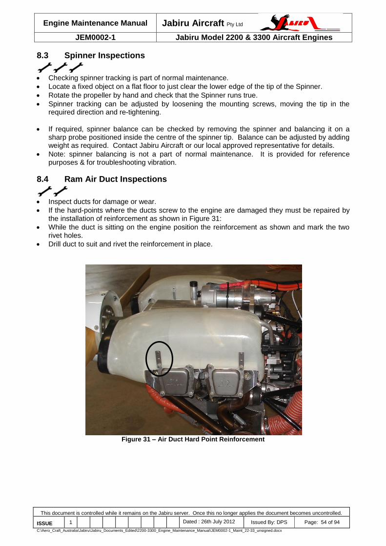
Engine Maintenance Manual Jabiru Aircraft Pty Ltd
JEM0002-1 Jabiru Model 2200 & 3300 Aircraft Engines
This document is controlled while it remains on the Jabiru server. Once this no longer applies the document becomes uncontrolled.
ISSUE 1 Dated : 26th July 2012 Issued By: DPS Page: 54 of 94
C:\Aero_Craft_Australia\Jabiru\Jabiru_Documents_Edited\2200-3300_Engine_Maintenance_Manual\JEM0002-1_Maint_22-33_unsigned.docx
8.3 Spinner Inspections
Checking spinner tracking is part of normal maintenance.
Locate a fixed object on a flat floor to just clear the lower edge of the tip of the Spinner.
Rotate the propeller by hand and check that the Spinner runs true.
Spinner tracking can be adjusted by loosening the mounting screws, moving the tip in the required direction and re-tightening.
If required, spinner balance can be checked by removing the spinner and balancing it on a sharp probe positioned inside the centre of the spinner tip. Balance can be adjusted by adding weight as required. Contact Jabiru Aircraft or our local approved representative for details.
Note: spinner balancing is not a part of normal maintenance. It is provided for reference purposes & for troubleshooting vibration.
8.4 Ram Air Duct Inspections
Inspect ducts for damage or wear.
If the hard-points where the ducts screw to the engine are damaged they must be repaired by the installation of reinforcement as shown in Figure 31:
While the duct is sitting on the engine position the reinforcement as shown and mark the two rivet holes.
Drill duct to suit and rivet the reinforcement in place.
Figure 31 – Air Duct Hard Point Reinforcement

Engine Maintenance Manual Jabiru Aircraft Pty Ltd
JEM0002-1 Jabiru Model 2200 & 3300 Aircraft Engines
This document is controlled while it remains on the Jabiru server. Once this no longer applies the document becomes uncontrolled.
ISSUE 1 Dated : 26th July 2012 Issued By: DPS Page: 55 of 94
C:\Aero_Craft_Australia\Jabiru\Jabiru_Documents_Edited\2200-3300_Engine_Maintenance_Manual\JEM0002-1_Maint_22-33_unsigned.docx
8.5 Oil & Filter Change
Oil & filter change at the interval noted in Table 13.
Before starting, carry out a visual check for leaks.
Cut the safety wire on sump plug, remove it & drain the oil while engine is still warm (not hot!).
Remove the old oil filter while the sump is draining. Ensure the oil seal of the old filter comes away from the engine with the filter.
Inspect the sump plug seal & replace if worn or damaged.
Re-fit the sump plug. Tighten to the tension given in Table 10 & lock wire per Section 8.20
Take a new oil filter and fill with new oil. Lubricate the seal on the base of the filter with new engine oil and fit the filter to the engine. Tighten until seal touches the engine and then turn it an additional ¾ - 1 full turn. DO NOT apply excess torque to the filter – it should be possible to install the filter by hand. If tools are used to tighten the filter take care not to damage it – the filter walls are very thin and slight damage such as dents or scratches can result in subsequent filter failure.
CAUTION Jabiru Aircraft recommend that the oil filter is not safety wired. Experience has shown that the filter will not move if installed correctly and that using safety wire, hose clamps etc can
potentially damage the filter and lead to failure.
Fill with oil. (approx 2.3 litres for 2200 engine, 3.5 litres for 3300 engine)
Check oil level then run the engine. The MAX mark must not be exceeded after the engine has been run to ensure that all lines, filters etc are full.
Use only registered brand oils meeting the specification detailed in Section 3.8.
DO NOT drain the oil cooler during a normal oil change. The cooler holds only a small amount of old oil which has negligible effect on the new oil. Taking the hoses on & off the cooler can prematurely age the oil lines and lead to hoses slipping off the cooler.
Clean any oil residue from the oil / filter change before returning to service.
8.6 Oil Pressure Relief Valve Adjustment
Remove the oil filter.
Remove the oil cooler adaptor. Note that to gain sufficient slack in the oil lines it may be necessary to remove the oil cooler from its mounting.
Remove the circlip and draw the valve assembly out of the case.
Inspect the sealing face of the relief valve plunger. If there are visible nicks or damage – or if the plunger is made from brass – then it must be replaced. If a new plunger is to be installed it must be lapped to the front restraining washer as noted in the Jabiru Engine Overhaul Manual.
If the pressure of the engine needs to be increased another washer can be added behind the spring (item 2 in Figure 32 below). If the pressure needs to be reduced then a washer can be removed.
Re-assemble the valve.
Ensure that the spring is not coil-bound: press on the tip of the oil valve plunger and ensure there is a minimum of 1mm movement.

Engine Maintenance Manual Jabiru Aircraft Pty Ltd
JEM0002-1 Jabiru Model 2200 & 3300 Aircraft Engines
This document is controlled while it remains on the Jabiru server. Once this no longer applies the document becomes uncontrolled.
ISSUE 1 Dated : 26th July 2012 Issued By: DPS Page: 56 of 94
C:\Aero_Craft_Australia\Jabiru\Jabiru_Documents_Edited\2200-3300_Engine_Maintenance_Manual\JEM0002-1_Maint_22-33_unsigned.docx
Figure 32 – Oil Pressure Relief Valve Assembly
8.7 Air Intake Filter
Remove the front of the air filter housing & extract filter.
Clean filter by removing from the intake housing & blowing compressed air against the direction of the intake flow.
For operation in heavy dust conditions, clean air filter at shorter intervals than recommended for normal conditions.
A clogged or wet filter will reduce engine performance as well as promote premature engine wear.

Engine Maintenance Manual Jabiru Aircraft Pty Ltd
JEM0002-1 Jabiru Model 2200 & 3300 Aircraft Engines
This document is controlled while it remains on the Jabiru server. Once this no longer applies the document becomes uncontrolled.
ISSUE 1 Dated : 26th July 2012 Issued By: DPS Page: 57 of 94
C:\Aero_Craft_Australia\Jabiru\Jabiru_Documents_Edited\2200-3300_Engine_Maintenance_Manual\JEM0002-1_Maint_22-33_unsigned.docx
8.8 Ignition Coil Gap Adjustment
For best performance the gap between the ignition coil and the flywheel magnets must be set
to the specification given in Section 3.4.
To set gap, use a piece of gauge material the correct thickness. A metal gauge can be used, as can alternatives made from plastic etc.
Loosen the screws holding the coil in place, move it away from the flywheel and then re-tighten. This is to increase the size of the gap and allow the gauge to be inserted.
Rotate the crank until a magnet pole plate aligns with the coil being adjusted.
Place the gauge material between the coil and the flywheel magnet. Loosen the screws holding the coil and allow the magnets to suck it against the gauge.
Tighten the screws, locking the coil in place.
Rotate the crank to draw the gauge material from between the coil and the flywheel.
When both coils are adjusted check that the gap is the same for both coils and all magnet pole plates.
CAUTION When working at the rear of the engine care must be taken to ensure no metallic materials
are captured by the ignition or alternator magnets.
8.9 High Tension Lead Inspection & Maintenance
Figure 6 above shows the High-Tension lead connections between the distributors and the
spark plugs.
At the intervals noted in Table 13 high tension leads must be inspected and, if necessary, adjusted.
Inspect the length of each lead, checking for cracked or damaged insulation. Particularly check areas where the lead may have been rubbing against other items in the engine bay.
Check the fit of the high-tension lead caps onto the distributor and spark plugs. Under the heat and vibration of operation the lead caps may gradually work their way off the distributor – particularly if lubricant has been applied to the caps. If lubricant is found, clean it off using a cleaner which does not leave a residue (Ether-based starting sprays can often be used).
Visually check the metal contacts inside the caps. If the fit is loose or if the contact is visibly damaged as shown in Figure 33 then a screwdriver or similar must be used to re-shape the contact (it should be round) and to re-size it for a better fit – for a spark plug the diameter of the contact needs to be reduced to tighten while for a distributor cap it needs to be expanded. Each cap should fit with a clear “click” as it connects to the distributor cap or spark plug. Take care not to over-bend and contact and replace any which are damaged.
Figure 33 – Adjusting High Tension Lead Caps

Engine Maintenance Manual Jabiru Aircraft Pty Ltd
JEM0002-1 Jabiru Model 2200 & 3300 Aircraft Engines
This document is controlled while it remains on the Jabiru server. Once this no longer applies the document becomes uncontrolled.
ISSUE 1 Dated : 26th July 2012 Issued By: DPS Page: 58 of 94
C:\Aero_Craft_Australia\Jabiru\Jabiru_Documents_Edited\2200-3300_Engine_Maintenance_Manual\JEM0002-1_Maint_22-33_unsigned.docx
8.10 Spark Plugs
Do not use steel or brass brushes for cleaning & never sandblast plugs.
Clean with plastic brush in a solvent.
Check electrode gap & if necessary, adjust to the gap given in Section 3.4 by carefully bending the electrode.
CAUTION DO NOT reduce the electrode gap by tapping the plug against a hard object – damage to the
insulator can result.
Recommended Plugs: NGK D9EA. Note that spark plug terminal nuts must be used (Figure 34)
Use suitable anti-seize on thread and install to the torque setting given in Table 10. Note that engine must be cold to accurately set plug tension.
When using CHT sensors equipped with a ring terminal under the spark plug ensure the ring terminals are centred over the plug.
CAUTION Off-centre terminals will give a false, high CHT reading.
Figure 34 – Spark Plug Terminal Nut
8.11 Carburettor Inspection & Adjustment
Check carburettor joints for degradation.
Check carburettor linkage for full & free movement, correct positioning of stops and security. Ensure that when the choke is selected fully ON and released the arm on the carburettor does not move – if the choke arm springs back slightly when the control in the cabin is released this can result in difficulty starting the engine. When in the ON position the choke lever on the carburettor must remain in the fully ON position regardless of if there is a hand on the control in the cabin.
The carburettor automatically adjusts the mixture to account for altitude – there is no provision for in-flight mixture adjustment as standard.
Ensure that the carburettor sense tube is connected from the carburettor to a fitting on the filtered side of the hot air mixer box.
Idle stop screw is a 7mm screw against throttle lever. Adjust its position to adjust engine idle speed. Note that the throttle idle stops inside the cabin may also need to be adjusted.
Standard idle mixture screw position is 1-1/4 turns out. Fine adjustment may be necessary to give a smooth idle.
Remove the spring clip and detach the bowl from the carburettor. Measure the distance from the fuel surface to the top of the bowl – it should be approximately 12mm.
Inspect the bowl for dirt or contamination and clean if required. Inspect the visible jets of the carburettor and clean if required.
Spark plug terminal nut

Engine Maintenance Manual Jabiru Aircraft Pty Ltd
JEM0002-1 Jabiru Model 2200 & 3300 Aircraft Engines
This document is controlled while it remains on the Jabiru server. Once this no longer applies the document becomes uncontrolled.
ISSUE 1 Dated : 26th July 2012 Issued By: DPS Page: 59 of 94
C:\Aero_Craft_Australia\Jabiru\Jabiru_Documents_Edited\2200-3300_Engine_Maintenance_Manual\JEM0002-1_Maint_22-33_unsigned.docx
Gently lift the floats of the carburettor with the bowl removed until the float needle touches its seat. The floats should be approximately level when the needle touches the seat. If necessary the float assembly can be removed by pressing out the pivot pin and the float height adjusted by gently bending the arm which connects to the float needle.
Inspect the condition of the seal between carburettor and bowl.
Re-fit the bowl and snap the clip back in place.
CAUTION Ensure clip is properly on: pressed up against the stopper cast into the bowl.
8.11.1 Tuning
The mixture is set by selecting jet sizes. As supplied, the engine has jets to suit a majority of installations. However, the mixture may be affected by many variables and in some cases adjustment will be necessary.
It is strongly recommended that for any new installation a thorough assessment of the engine’s fuel/air mixture is carried out. This may be done by EGT sensors or Lambda type sensors. Details are given in the engine installation manual and Jabiru Service Bulletin JSB018.
CAUTION Do not change carburettor settings without consulting with Jabiru Aircraft or our local authorised representative. If EGT readings fall outside the range given above, contact
Jabiru Aircraft or our local authorised representative.
Spark plug colour can be used as a general indicator of the health of the engine and the suitability of the fuel/air mixture: a. Brown to Dark Brown :- Plug & calibration is correct. b. Velvet Black:- Mixture too rich. Check choke. Insufficient air intake. Check for clogged air
filter. c. Oily, Glossy Coating:- Misfiring. Too much oil in combustion chamber. Worn cylinder piston
rings. d. Whitish with Melt Droplets:- Mixture too lean. Leaking valves.
CAUTION
This guide is only relevant when running the engine on AVGAS. Unleaded fuels give different plug colours which are generally unsuitable for use in evaluating engine tuning.
The plug colour reflects the most recent running of the engine – if the engine has run at idle for some time the plug colour will reflect the mixture at idle.
WARNING
Spark plug colour is a very general guide only. Tuning adjustments must ONLY be made on the basis of EGT or Lambda sensor results.
DO NOT ADJUST ENGINE TUNING BASED ON SPARK PLUG COLOURS ALONE

Engine Maintenance Manual Jabiru Aircraft Pty Ltd
JEM0002-1 Jabiru Model 2200 & 3300 Aircraft Engines
This document is controlled while it remains on the Jabiru server. Once this no longer applies the document becomes uncontrolled.
ISSUE 1 Dated : 26th July 2012 Issued By: DPS Page: 60 of 94
C:\Aero_Craft_Australia\Jabiru\Jabiru_Documents_Edited\2200-3300_Engine_Maintenance_Manual\JEM0002-1_Maint_22-33_unsigned.docx
8.12 Distributor & Rotor Inspection & Adjustment
Remove the clamps and rotors from the engine. Inspect the distributor caps, rotor button and
rotor for damage or wear.
The rotor is glued to the distributor shaft. If it or the distributor oil seal must be replaced, carefully work the old rotor off the shaft using screwdrivers as levers.
Clean any residue of the old glue off the distributor shaft.
If the distributor seal is to be replaced, remove the old seal using a pick & pliers.
Visually inspect the distributor shaft for wear from the seal. A groove deeper than 0.5mm (in radius) will require replacement of the shaft.
Apply a suitable grease to the inside of the replacement seal and press it into place.
Clean the distributor shaft and the inside of the distributor rotor using a residue-free cleaner.
Mix a small batch of 5-minute epoxy adhesive combined with a small amount of filler (such as cotton fibre flock). Apply a pea-sized amount of adhesive to the inside of the rotor cap. Apply a similar amount to the rotor shaft. Press the rotor onto the shaft, ensuring it goes all the way on. Wipe off any excess glue and allow to set.
Test fit the distributor, ensuring it fits over the new rotor. Tighten the distributor clamps. Turn the crankshaft through 2 full revolutions by hand, monitoring the distributor for any interference with the new rotor.
Re-fit the high-tension leads.

Engine Maintenance Manual Jabiru Aircraft Pty Ltd
JEM0002-1 Jabiru Model 2200 & 3300 Aircraft Engines
This document is controlled while it remains on the Jabiru server. Once this no longer applies the document becomes uncontrolled.
ISSUE 1 Dated : 26th July 2012 Issued By: DPS Page: 61 of 94
C:\Aero_Craft_Australia\Jabiru\Jabiru_Documents_Edited\2200-3300_Engine_Maintenance_Manual\JEM0002-1_Maint_22-33_unsigned.docx
8.13 Fuel System
Replace fuel filters at the intervals noted in Table 13.
Check flexible lines for condition and replace any which are hard, cracked or softened. Inspect for fittings for wear or damage. Verify correct function of tap(s) and that correct fuel tap placards are fitted.
Note mandatory replacement requirements of Section 7.3.
Fire sleeves: Check for wear and correct fitment per Figure 35. Note the fire sleeve overlapping the hose clamps and reaching to the end of the fuel hose.
Figure 35 – Fuel Hose Assy – Engine Bay

Engine Maintenance Manual Jabiru Aircraft Pty Ltd
JEM0002-1 Jabiru Model 2200 & 3300 Aircraft Engines
This document is controlled while it remains on the Jabiru server. Once this no longer applies the document becomes uncontrolled.
ISSUE 1 Dated : 26th July 2012 Issued By: DPS Page: 62 of 94
C:\Aero_Craft_Australia\Jabiru\Jabiru_Documents_Edited\2200-3300_Engine_Maintenance_Manual\JEM0002-1_Maint_22-33_unsigned.docx
8.14 Tachometer and Sender
Many apparent engine problems can be caused through inaccurate tachometers. Where
engine performance is observed to be outside limits, the tachometer should be checked against a calibrated instrument before other troubleshooting is attempted.
Two types of sender have been used on Jabiru Engines as shown in Figure 36 (Type 1) and Figure 37 (Type 2).
For the Type 1 sender, the gap between the tip of the sender and the tags on the flywheel is 0.4mm (0.016"). The sender must have at least 60% covered by the tags fitted to the gearbox side of the flywheel. Ensure both tags are equal distance from sender.
CAUTION The tip of the sender is delicate and easily damaged. Care must be taken when adjusting
the sender gap to ensure the tag does not hit the sender.
Type 2 senders are installed per the requirements of Figure 37.
Figure 36 – Tacho Sender #1
Figure 37 – Tacho Sender #2
Tacho post with sender installed

Engine Maintenance Manual Jabiru Aircraft Pty Ltd
JEM0002-1 Jabiru Model 2200 & 3300 Aircraft Engines
This document is controlled while it remains on the Jabiru server. Once this no longer applies the document becomes uncontrolled.
ISSUE 1 Dated : 26th July 2012 Issued By: DPS Page: 63 of 94
C:\Aero_Craft_Australia\Jabiru\Jabiru_Documents_Edited\2200-3300_Engine_Maintenance_Manual\JEM0002-1_Maint_22-33_unsigned.docx
8.15 Head Bolt Tension Check
Remove the air ducts to allow access to the cylinder heads. Note that ducts do not need to be
completely removed from the engine – for example, on current model Jabiru Aircraft the retaining screws and springs are disconnected, the high tension leads disconnected from the spark plugs and the ducts may be swung away to allow access.
Remove the rocker covers and the 1/8 NPT plug which gives access to the lower head bolt (see at the location indicated as bolt #5 in Figure 38).
If the engine has been operating in a corrosive environment (such as coastal areas) it is possible for the cylinder head screws to rust in place. In these applications it may be necessary to loosen head screws by approximately ¼ of a turn to check for rust before re-applying screw torque. Where a screw is loosened and re-tightened the screw must be set to the “new installation torque” given in Table 10. Note any excessively loose screws.
When screws are not loosened before re-torquing they are checked to the “subsequent check” torque value noted in Table 10.
When fitted, head screws are lubricated with a suitable thread lubricant. Note that this is applied to the threads only (not the head of the screw) and to the torque settings given are therefore still considered to be a “dry” torque. In corrosive environments it is recommended to periodically remove the screws, inspect and re-apply thread lubricant. Excessively corroded screws must be replaced with new approved parts.
Tensioning is carried out when the engine is cold.
Torque the screws in the order shown in Figure 38.
Note any screws which require more than 1/4 - 1/3 of a turn to reach the set tension as this may be an indication of issues such as excess temperature in service.
Re-fit the 1/8 NPT plug to close the access hole to the bottom head bolt. Torque to the setting given in Table 10.
Re-fit the rocker cover to the head, ensuring that the seal is correctly positioned in the groove in the head.
Re-fit the ram air cooling ducts. CAUTION
Do not over-tighten. Over-tightening will eventually loosen fit between plug & head to the point where the plug will not be secure.
Figure 38 – Head Bolt Locations
1
2
6
4
5
3

Engine Maintenance Manual Jabiru Aircraft Pty Ltd
JEM0002-1 Jabiru Model 2200 & 3300 Aircraft Engines
This document is controlled while it remains on the Jabiru server. Once this no longer applies the document becomes uncontrolled.
ISSUE 1 Dated : 26th July 2012 Issued By: DPS Page: 64 of 94
C:\Aero_Craft_Australia\Jabiru\Jabiru_Documents_Edited\2200-3300_Engine_Maintenance_Manual\JEM0002-1_Maint_22-33_unsigned.docx
8.16 Valve Clearance Adjustment (Solid Lifter Engines Only)
Always carry out a cylinder head bolt tension check (Section 8.15) before adjusting valve
clearances.
Valve clearance must be adjusted to: Inlet 0.254mm (.010") Exhaust 0.254mm (.010")
Adjust the tappets when the engine is cold.
Adjust the valve clearances use the following procedure:
1. Remove the cowls, ram air ducts, rocker covers & at least 1 spark plug from each cylinder. 2. Start with a particular cylinder head – for example the rear head on the pilot’s side of the
aircraft. Turn the crankshaft to the point where the valve is fully depressed then rotate it through another whole revolution. This will place the follower exactly on the “back” of the cam where there is no lift. Note that the crank should always be turned in the direction of its normal rotation.
3. Using a spanner and screwdriver (or special tool as shown below) adjust the clearance. 4. Repeat this process for each valve in the engine, working systematically from 1 head to the
next. 5. When all valves have been adjusted, re-assemble the engine.
Figure 39 – Valve Clearance Adjustment (Solid Lifter)
CAUTION Continued operation with incorrectly adjusted tappets will result in damage to valves, valve
seats, valve guides & overhead gear. Correct setting of valve clearance is critical to the safe operation of the engine & must be
carried out carefully, following the procedures given herein exactly.

Engine Maintenance Manual Jabiru Aircraft Pty Ltd
JEM0002-1 Jabiru Model 2200 & 3300 Aircraft Engines
This document is controlled while it remains on the Jabiru server. Once this no longer applies the document becomes uncontrolled.
ISSUE 1 Dated : 26th July 2012 Issued By: DPS Page: 65 of 94
C:\Aero_Craft_Australia\Jabiru\Jabiru_Documents_Edited\2200-3300_Engine_Maintenance_Manual\JEM0002-1_Maint_22-33_unsigned.docx
8.17 Compression Check
Always carry out a cylinder head bolt tension check (Section 8.15) and, where applicable, valve
clearance checks (Section 8.16) before testing compression.
8.17.1 Compression Gauge:
Measure compression using a compression tester. Readings are taken with fully open throttle valve at engine oil temperature between 30° & 70°C (90° to 160°F).
If readings are below 6 bar (90 psi) a check of the pistons, cylinders, valves & cylinder heads must be undertaken.
CAUTION Ensure ignitions are OFF and all personnel & equipment are well clear of propeller.
8.17.2 Pressure Differential Test:
As an alternative to a compression test, a pressure differential test (Leak down) can be carried out. This is a much better test of the condition of rings, bore, head sealing and valve. This is the normal test used in aviation and is strongly recommended by Jabiru Aircraft. It requires specific test equipment.
The test is carried out with the engine in warm to hot condition.
Remove 1 spark plug from the cylinder to be tested and fit the leak-down tester in its place.
Pressure input is set to 80 PSI; a second gauge reads the differential. This is done with piston on TDC on the firing stroke. A SUN or BOSCH tester pressure loss or leakage tester is used. Maximum allowable pressure loss is 25% - therefore a differential of lower than 80/60 indicates a problem.
CAUTION The propeller must be restrained as the air pressure applied will tend to rotate the crank.
While the pressure is being applied, lightly tap the tip of the rocker arm where it touches the valve using a soft hammer. The aim is to bounce the valve off its seat by around 1 – 2mm. The air pressure applied by the tester will press the valve back into place quickly and any debris which had gathered around the valve sealing face will be jolted free and blown out of the combustion chamber. This will often improve the valve seal enough to raise the compression of the cylinder by several psi.
A Pressure Differential Tester can be made by placing an orifice of 1 mm ID and 3mm length between two pressure gauges. This will give the same result as with the above instrument.
Note: for commercial use, proper calibration of this tool is necessary.
Poor compression can be an indication of a serious problem. For example, continued operation with poor compression due to a poorly-sealing valve can lead to eventual valve failure and heavy damage to the piston, con-rod, barrel and head. If low compression is found which cannot be solved by reference to the Troubleshooting section below, please contact Jabiru Aircraft or our local authorized representative.
After testing, note the results in the maintenance worksheet and re-assemble the engine.
8.17.3 Identifying Compression Leaks
Problems can be better identified using the leak down: i) Remove the dipstick and listen at the opening. Air leaking through here indicates worn
rings or bore ii) Disconnect the SCAT hose from the carburettor intake and listen at the opening. Air
leaking from carburettor indicates a poor intake valve seal. iii) Listen at the exhaust outlets – air leaking from exhaust indicates a poor exhaust valve
seal. iv) Apply a small amount of soapy water to the base of the head, where it mounts to the
cylinder. A head seal leak will be indicated by blowing bubbles in the soap mixture.

Engine Maintenance Manual Jabiru Aircraft Pty Ltd
JEM0002-1 Jabiru Model 2200 & 3300 Aircraft Engines
This document is controlled while it remains on the Jabiru server. Once this no longer applies the document becomes uncontrolled.
ISSUE 1 Dated : 26th July 2012 Issued By: DPS Page: 66 of 94
C:\Aero_Craft_Australia\Jabiru\Jabiru_Documents_Edited\2200-3300_Engine_Maintenance_Manual\JEM0002-1_Maint_22-33_unsigned.docx
Alternative to listening, a rubber glove or similar can be stretched over the opening being checked (carburettor inlet, exhaust outlet, crankcase vent); if the glove inflates this indicates the location and rate of the leak.
With the problem narrowed down, correction work can more easily be carried out.
8.18 Fuel Flow Rate Test
Disconnect the fuel line from the mechanical fuel pump in the engine compartment.
Have a second person stand by to catch any fuel that flows out of the line in a container with accurate volume marks. Ensure the free end of the fuel hose is held level with the carburettor fuel inlet.
Turn electric fuel pump on and pump fuel through the lines into container. Ensure there is about 1 litre per minute flow rate (50-60 L/hr).
Re-connect the fuel line.
8.19 Hydraulic Valve Lifter Maintenance
The Hydraulic Valve Lifters used in the engine automatically adjust for any valve movement, so
periodic adjustment of the valve clearances is not required, however the valve lifters are a serviceable item and some monitoring is required to ensure they are working properly.
EITHER – Remove each rocker cover and check that each lifter has not collapsed. This is done by turning the crankshaft so that the valve is fully in the closed position, then feeling the rocker by hand. There should be no free rotation of the rocker. Press down on the pushrod end of the rocker – the lifter should feel hard, with minimal movement possible under thumb pressure. Note that the correct method for finding this point is to turn the crank until the valve is fully open, then turning the crankshaft through one complete revolution to rotate the cam lobe away from the lifter.
OR – after the service, idle the engine, listen for loud tapping noises and feel for rough running. This must be carried out with the cowls removed. Note that due to the need to have a person at the controls of the aircraft, this is a two-person job.
CAUTION: Whenever the engine is running there must be a qualified person inside the aircraft, at the
controls. Under NO circumstances run the engine without a qualified person at the controls
Troubleshooting information is given in Section 9.16
Air can be caught inside the lifters after maintenance. Running the engine at a high idle - approx 1500 RPM – will expel the air but may take up to 15 minutes. When fitting lifters after inspection or maintenance they should be filled by injecting oil into the hole in the side of the lifter. Care must be taken to ensure all air is removed.
Several different hydraulic lifters have been used in Jabiru 2200 engines. The cam P/No. fitted to the engine must be known when ordering replacement lifters. This information can be found from the engine’s S/No. or from its overhaul records. The type of lifter must be matched correctly to the cam design. Use of mismatched parts will cause reduced engine power and possible engine damage.
Figure 40 shows identification markings on a cam – it has two “rings” machined at the oil pump end and two small “spots” machined at the drive gear end. Similarly, other cams are marked with one “ring”, and one “spot”. Engines assembled with these cam types must use a Jabiru P/No. PE4A001 Hydraulic Lifter.
Cams manufactured without any identification “rings” or “spots” must use a Jabiru P/No. 4A294C0D Hydraulic Lifter.
The different types of Hydraulic Lifter are not marked and the difference requires disassembly and careful measuring using a micrometer to detect. Accordingly, care must be taken to ensure different types of lifter are not confused during maintenance.

Engine Maintenance Manual Jabiru Aircraft Pty Ltd
JEM0002-1 Jabiru Model 2200 & 3300 Aircraft Engines
This document is controlled while it remains on the Jabiru server. Once this no longer applies the document becomes uncontrolled.
ISSUE 1 Dated : 26th July 2012 Issued By: DPS Page: 67 of 94
C:\Aero_Craft_Australia\Jabiru\Jabiru_Documents_Edited\2200-3300_Engine_Maintenance_Manual\JEM0002-1_Maint_22-33_unsigned.docx
Figure 40 – Cam Identification Markings
Hydraulic Lifters can be ‘bled’ back while installed by using a suitable tool to push rocker/pushrod assembly back to enable a small gap on rocker to valve tip. Total bleed-back is less than 2 mm. More details are given in the engine overhaul manual.
8.19.1 Hydraulic Lifter Removal
If required, hydraulic lifters can be removed for inspection using the following method:
a. Remove the air ducts and rocker covers from the engine. b. Ensure the piston of the cylinder being worked on is at the bottom of its stroke. c. Use a valve compression tool (Figure 15) to open both valves slightly. This takes the
spring load off the rockers and allows their removal. d. Remove the central screw holding the rocker shaft in place. e. Remove the rocker pivot shaft, rockers and pushrods from the cylinder head to be
inspected. Note that for a 3300 engine it is easier to remove the entire head if one of the middle cylinders needs to be worked on.
f. Remove the pushrod tube retaining circlips from the cylinder head and slide the pushrod tubes out through the head.
g. Remove the hydraulic lifter adaptors from the crankcase h. Remove the lifters.
Whenever lifters are removed the working face of the cam and the lifter should be inspected for damage. If damage is found, contact Jabiru Aircraft P/L or our local representative for further guidance.
Note that this is not a part of normal scheduled maintenance but may be necessary for troubleshooting.
8.19.2 Valve Rockers
The condition of the bushes fitted to the valve rockers must be monitored. This can be done by
a visual inspection with the rocker cover removed – check for visible movement of the rocker on the shaft, visible degradation of the bush material etc.
This should be done as a part of the hydraulic lifter inspections noted above.
Cam identification markings

Engine Maintenance Manual Jabiru Aircraft Pty Ltd
JEM0002-1 Jabiru Model 2200 & 3300 Aircraft Engines
This document is controlled while it remains on the Jabiru server. Once this no longer applies the document becomes uncontrolled.
ISSUE 1 Dated : 26th July 2012 Issued By: DPS Page: 68 of 94
C:\Aero_Craft_Australia\Jabiru\Jabiru_Documents_Edited\2200-3300_Engine_Maintenance_Manual\JEM0002-1_Maint_22-33_unsigned.docx
8.20 Ignition Coil & Alternator Electrical Inspections
Figure 41 – Ignition Coil Tests
Use a multimeter to measure the primary resistance (from the earth terminal to the iron core as shown above). It should be 0.8 Ω to 1.0 Ω for Honda coils and 1.7 Ω to 1.8 Ω for Jabiru coils.
Use a multimeter to measure the secondary resistance (from the high tension lead to the iron core as shown above) it should be between 5.9 KΩ to 7.1 KΩ for Honda coils and 18 KΩ to 30 KΩ for Jabiru coils.
Alternator resistance: use a multimeter to measure the resistance of the windings, which should be between 0.4Ω to 1.1 Ω. Resistance to ground should be infinite.
Figure 42 – Different Ignition Coil Models (Honda on Left, Jabiru on Right).
8.21 Flywheel Screw Inspection
Remove the alternator stator to allow access to the flywheel. Where equipped the vacuum
pump must also be removed.
Set a torque wrench to 24 lb.ft for engines using 5/16” or 3/8” flywheel screws. Use 15 lb.ft for older 2200 engines using 1/4” screws.
Check each screw using the torque wrench to see if any are loose or broken.
If any rotate at this tension then ALL flywheel screws must be removed and replaced with new, approved, screws. The procedure for replacing these screws must be followed precisely. Details are provided in the Jabiru Engine Overhaul Manual.

Engine Maintenance Manual Jabiru Aircraft Pty Ltd
JEM0002-1 Jabiru Model 2200 & 3300 Aircraft Engines
This document is controlled while it remains on the Jabiru server. Once this no longer applies the document becomes uncontrolled.
ISSUE 1 Dated : 26th July 2012 Issued By: DPS Page: 69 of 94
C:\Aero_Craft_Australia\Jabiru\Jabiru_Documents_Edited\2200-3300_Engine_Maintenance_Manual\JEM0002-1_Maint_22-33_unsigned.docx
8.22 Use of Safety Wire
Only stainless steel safety wire is used on the Jabiru Aircraft Engine.
There are two methods of safety wiring; the double-twist method that is most commonly used, and the single-wire method used on screws, bolts, and/or nuts in a closely-spaced or closed-geometrical pattern such as a triangle, square, rectangle, or circle. The single-wire method may also be used on parts in electrical systems and in places that are difficult to reach. Single-wire safetying is not used on the Jabiru Aircraft Engine.
When using double-twist method of safety wiring, 0.032 inch minimum diameter wire should be used on parts that have a hole diameter larger than 0.045 inch (1.1mm). When using the single-wire method, the largest size wire that the hole will accommodate should be used.
CAUTION Care must be taken not to confuse steel with Aluminium wire.
There are many combinations of safety wiring with certain basic rules common to all applications. These rules are as follows. a. When bolts, screws, or other parts are closely grouped, it is more convenient to safety wire
them in series. The number of bolts, nuts, screws, etc., that may be wired together depends on the application.
b. Drilled boltheads and screws need not be safety wired if installed with self-locking nuts. c. To prevent failure due to rubbing or vibration, safety wire must be tight after installation. d. Safety wire must be installed in a manner that will prevent the tendency of the part to
loosen. e. Safety wire must never be over-stressed. Safety wire will break under vibrations if twisted
too tightly. Safety wire must be pulled taut when being twisted, and maintain a light tension when secured (Figure 44).
f. Safety-wire ends must be bent under and inward toward the part to avoid sharp or projecting ends, which might present a safety hazard.
g. Safety wire inside a duct or tube must not cross over or obstruct a flow passage when an alternate routing can be used.
h. Check the units to be safety wired to make sure that they have been correctly torqued, and that the wiring holes are properly aligned to each other. When there are two or more units, it is desirable that the holes in the units be aligned to each other. Never over-torque or loosen to obtain proper alignment of the holes. It should be possible to align the wiring holes when the bolts are torqued within the specified limits. However, if it is impossible to obtain a proper alignment of the holes without under-torquing or over-torquing, try another bolt which will permit proper alignment within the specified torque limits.
i. To prevent mutilation of the twisted section of wire, when using pliers, grasp the wires at the ends. Safety wire must not be nicked, kinked, or mutilated. Never twist the wire ends off with pliers; and, when cutting off ends, leave at least four to six complete turns (1/2 to 5/8 inch long) after the loop. When removing safety wire, never twist the wire off with pliers. Cut the safety wire close to the hole, exercising caution.
j. Install safety wire where practicable with the wire positioned around the head of the bolt, screw, or nut, and twisted in such a manner that the loop of the wire fits closely to the contour of the unit being safety wired.
When using a wire twister (safety wire pliers), grip the wire in the jaws of the wire twister and slide the outer sleeve down with your thumb to lock the handles or lock the spring-loaded pin.
Pull the knob, and the spiral rod spins and twists the wire.
Squeeze handles together to release wire. CAUTION
When using wire twisters, and the wire extends 3 inches beyond the jaws of the twisters, loosely wrap the wire around the pliers to prevent whipping and possible personal injury.
Excessive twisting of the wire will weaken the wire.

Engine Maintenance Manual Jabiru Aircraft Pty Ltd
JEM0002-1 Jabiru Model 2200 & 3300 Aircraft Engines
This document is controlled while it remains on the Jabiru server. Once this no longer applies the document becomes uncontrolled.
ISSUE 1 Dated : 26th July 2012 Issued By: DPS Page: 70 of 94
C:\Aero_Craft_Australia\Jabiru\Jabiru_Documents_Edited\2200-3300_Engine_Maintenance_Manual\JEM0002-1_Maint_22-33_unsigned.docx
Figure 43 – Safety Wire Details
Figure 44 – Safety Wire Installation Using a Twister/Pliers & By Hand

Engine Maintenance Manual Jabiru Aircraft Pty Ltd
JEM0002-1 Jabiru Model 2200 & 3300 Aircraft Engines
This document is controlled while it remains on the Jabiru server. Once this no longer applies the document becomes uncontrolled.
ISSUE 1 Dated : 26th July 2012 Issued By: DPS Page: 71 of 94
C:\Aero_Craft_Australia\Jabiru\Jabiru_Documents_Edited\2200-3300_Engine_Maintenance_Manual\JEM0002-1_Maint_22-33_unsigned.docx
8.23 Engine Overhaul and TBO
These are carried out only by the manufacturer, Jabiru Aircraft Pty Ltd or by a specifically approved Jabiru Engine Service Centre (contact Jabiru for details).
The engine must be sent in a complete state, with logbook, to Jabiru (or the Approved Service Centre) after reaching the TBO limit. In some cases a questionnaire may be supplied regarding the service life of the engine so far. In these cases the questionnaire must be filled out as completely as possible & returned with the engine.
Changes to TBO due to operational experience will be advised by Jabiru via Service Bulletin
Engines have full overhauls at 2000 hours with a Top End being done at around 1000 hours. This is also subject to certain conditions: overhauls are influenced by condition.
8.23.1 Full Overhaul
Full overhauls must be carried out as detailed in the latest approved revision of the Jabiru Engine Overhaul Manual.
During a full overhaul all parts are cleaned, measured, inspected and recorded in the prescribed build sheets in the manual. Parts that are replaced during a full overhaul include:- Pistons, gudgeons and circlips, rings, main bearings, conrod bearings, thrust bearings, conrod bolts, all orings gaskets and seals, fuel pump, valves, induction hoses, rubber oil feed tees, spark plugs, rotors, head bolts, intake/exhaust studs, fuel hose, oil filter, oil hoses, flywheel bolts, prop flange bolts, woodruff key (oil pump), crankcase through-bolts and crankcase studs. Cylinder, heads and dizzy shafts are usually replaced at a full overhaul, depending on condition.
As a part of the overhaul process the engine must be run-in. Again, the procedure given in the Jabiru Engine Overhaul Manual must be used. Details are given in that manual, however note that if the run in is performed on the ground large air cooling ducts and a large oil cooler must be used. The engine can also be run-in, in the aircraft in the air with caution, using the run in program as the guide. Section 4.10 Early Operation of an engine must be understood. Initial performance data must be recorded. New engines and engines overhauled by Jabiru Aircraft (Australia) are dispatched already run-in – no further running-in is required.
8.23.2 Top End Overhaul
Top End Overhauls must be carried out as detailed in the latest approved revision of the Jabiru Engine Overhaul Manual.
Parts replaced include:- Conrod bearings, pistons, gudgeon pins and circlips, rings, valves, all relevant O rings and gaskets, head bolts, spark plugs, induction hose joiners, rotors, relevant cap screws and fuel line. Other parts for inspection, measure and clean or replace are oil pump, starter, alternator, fuel pump, coils, ignition leads, oil seals, induction and exhaust capscrews, carby, heads and barrels.
As a part of the overhaul process the engine must be run-in. Again, the procedure given in the Jabiru Engine Overhaul Manual must be used. Details are given in that manual, however note that if the run in is performed on the ground large air cooling ducts and a large oil cooler must be used. The engine can also be run-in, in the aircraft in the air with caution, using the run in program as the guide. Section 4.10 Early Operation of an engine must be understood. Initial performance data must be recorded. New engines and engines overhauled by Jabiru Aircraft (Australia) are dispatched already run-in – no further running-in is required.

Engine Maintenance Manual Jabiru Aircraft Pty Ltd
JEM0002-1 Jabiru Model 2200 & 3300 Aircraft Engines
This document is controlled while it remains on the Jabiru server. Once this no longer applies the document becomes uncontrolled.
ISSUE 1 Dated : 26th July 2012 Issued By: DPS Page: 72 of 94
C:\Aero_Craft_Australia\Jabiru\Jabiru_Documents_Edited\2200-3300_Engine_Maintenance_Manual\JEM0002-1_Maint_22-33_unsigned.docx
8.24 Engine Removal Procedure
Table 15 – Engine Removal
No. Operation Tools Required
1 Remove Spinner and Propeller Phillips Screwdriver 7/16" Socket 7/16" Spanner
2 Remove Carby Heat hose from hot-air muff on muffler
Flat-bladed Screwdriver
3 Remove Air Inlet Hose from Carburettor and blank off Carburettor and Air Cleaner
Flat-bladed Screwdriver 2 Plugs
4 Disconnect Throttle Cable Long Nose Pliers
5 Disconnect Choke Lever Long Nose Pliers
6 Remove Oil Breather Line Flat-bladed Screwdriver
7 Remove Fuel Line from Fuel Pump and plug Fuel Line and Fuel Pump
Flat-bladed Screwdriver 1/4" Plugs
8 Remove starter Motor Cable from Solenoid 7/16" R/OE spanner
9 Disconnect Earth at Battery 10mm R/OE
10 Remove Oil Pressure Gauge Lead -
11 Remove Oil Temperature Gauge Lead -
12 Remove Hourmeter Lead (if fitted) Screwdriver
13 Remove Cylinder Head Temperature Gauge Lead - (disconnect at cold junction)
14 Remove Exhaust Gas temperature Gauge Lead -
15 Remove Tacho Lead -
16 Remove Left and Right Ignition Coil Leads -
17 Remove Muffler Assy 3/16" Ball End Allen Key
18 Undo Engine Mount Bolts 7/16" Tube Socket 7/16" Spanner
19 Remove Engine from Engine Mount Frame -

Engine Maintenance Manual Jabiru Aircraft Pty Ltd
JEM0002-1 Jabiru Model 2200 & 3300 Aircraft Engines
This document is controlled while it remains on the Jabiru server. Once this no longer applies the document becomes uncontrolled.
ISSUE 1 Dated : 26th July 2012 Issued By: DPS Page: 73 of 94
C:\Aero_Craft_Australia\Jabiru\Jabiru_Documents_Edited\2200-3300_Engine_Maintenance_Manual\JEM0002-1_Maint_22-33_unsigned.docx
8.25 Engine Installation
Table 16 – Engine Installation
No. Operation Tools Required
1 Fit engine to engine mount -
2 Torque engine mount bolts 7/16 Tube Socket 7/16 Ring Open End Spanner
3 Fit muffler (if not already fitted) and fit carburettor heat muff and hose
3/16 Ball End Allen Key
4 Connect left and right ignition coils leads -
5 Connect Tacho sender -
6 Connect exhaust gas temp (if fitted) -
7 Connect cylinder head sender 18mm Spark Plug socket
8 Connect hourmeter Screw Driver
9 Connect oil temp gauge sender
10 Connect oil pressure gauge sender
11 Connect starter 7/16 Ring Open End Spanner
12 Connect Battery (Earth lead first) 10mm Ring Open End Spanner
13 Connect fuel line Screw Driver
14 Connect Oil Breather Screw Driver
15 Connect Choke Cable Long Nose Pliers
16 Connect Throttle Cable Long Nose Pliers
17 Connect Air Inlet Screw Driver
18 Fit Propeller and spinner 7/16 Ring Open End Spanner 7/16 Torque Wrench Phillips Screw Driver
19 Fit Cooling Ducts 3/16 Allen Key
20 Prime Fuel system with electric pump and inspect for leaks
-
21 Check for oil. Fill if needed. 2200: 2.3L oil (2.43 US quarts) 3300: 3.5L oil (3.7 US quarts)
22 Wind over to get oil pressure -
23 Start and inspect for leaks -
24 Test Fly Note: First flight is a test flight: fly conservatively!
-
25 Remove Cowls and inspect for anything loose, rubbing or leaking.
-
26 Check Head bolt tensions torqued per Table 10 -
27 Carry out checks for first 5, 10 & 25 hours as noted above (Section 7)
-
28
If oil consumption is stable fill with W100 (W80 in cold conditions and W120 in very hot conditions). If still using oil remain on run in oil or seek advice from Jabiru Aircraft or local authorized representative
-

Engine Maintenance Manual Jabiru Aircraft Pty Ltd
JEM0002-1 Jabiru Model 2200 & 3300 Aircraft Engines
This document is controlled while it remains on the Jabiru server. Once this no longer applies the document becomes uncontrolled.
ISSUE 1 Dated : 26th July 2012 Issued By: DPS Page: 74 of 94
C:\Aero_Craft_Australia\Jabiru\Jabiru_Documents_Edited\2200-3300_Engine_Maintenance_Manual\JEM0002-1_Maint_22-33_unsigned.docx
8.26 Prop Strike Inspection
After ground contact with the propeller, check the crankshaft and prop flange for run out as
shown below.
Figure 45 – Dial Indicator Position for Crankshaft & Prop Flange Run Out
Remove one spark plug from each head.
Carefully sand off paint on crank diameter and prop flange where dial indicator will be located.
Position dial indicator onto crank as shown above and eliminate main bearing clearance by bearing down on crank when rotating. Rotate crankshaft to measure crankshaft run out, normally expect to see 0.01 - 0.03 mm, but if run out exceeds of 0.08 mm the crankshaft must be replaced.
Position dial indicator onto prop flange as shown above, eliminate end float by either pulling or pushing flange when rotating. Rotate prop flange to measure the face run out, normally expect to see 0.02 - 0.06 mm, but if run out exceeds 0.08 mm then replace the prop flange.
Note: - If the crankshaft run-out exceeds the above limit the engine has to be stripped and
the crankshaft replaced. - The flywheel retaining cap screws (6) need to be replaced after any prop strike.
Even if the above run out requirements are met and depending on the severity of the prop strike, it could be prudent that an engine strip be performed and the crankshaft MPI tested, as internal damage may have occurred and can only be revealed by stripping the engine.
The decision to run an engine after a prop strike and after carrying out the above run out checks, rests with the owner. If you have any doubt about the action to take, then consult the Jabiru factory or your Authorised Jabiru dealer for advice.
Engines running a non-Jabiru propeller (especially composite propellers), must check the tension of the 6 flywheel cap screws at each service to determine that the cap screws meet the torque requirement, if not, then replace the cap screws and apply Loctite to the screws on assembly.
WARNING

Engine Maintenance Manual Jabiru Aircraft Pty Ltd
JEM0002-1 Jabiru Model 2200 & 3300 Aircraft Engines
This document is controlled while it remains on the Jabiru server. Once this no longer applies the document becomes uncontrolled.
ISSUE 1 Dated : 26th July 2012 Issued By: DPS Page: 75 of 94
C:\Aero_Craft_Australia\Jabiru\Jabiru_Documents_Edited\2200-3300_Engine_Maintenance_Manual\JEM0002-1_Maint_22-33_unsigned.docx
If an engine stoppage due to force is not recorded in the logbook and not advised to Jabiru, the liability for all subsequent and consequential damage will remain with
the owner. This applies to both prior to and after engine overhaul. If a crankshaft has been severely
stressed but measurements and MPI testing indicates a sound item it is Jabiru policy to not re-use, but replace with a new crankshaft.
8.27 Propeller Flange Installation / Removal
Details of this procedure are provided in the Jabiru Engine Overhaul Manual.

Engine Maintenance Manual Jabiru Aircraft Pty Ltd
JEM0002-1 Jabiru Model 2200 & 3300 Aircraft Engines
This document is controlled while it remains on the Jabiru server. Once this no longer applies the document becomes uncontrolled.
ISSUE 1 Dated : 26th July 2012 Issued By: DPS Page: 76 of 94
C:\Aero_Craft_Australia\Jabiru\Jabiru_Documents_Edited\2200-3300_Engine_Maintenance_Manual\JEM0002-1_Maint_22-33_unsigned.docx
9 Trouble Shooting
9.1 Engine Won't Start
Possible Cause Remedy
1) Ignition OFF Switch ON (Note spark will be produced when the primary coil is NOT earthed – i.e. ignitions are ON when switches are OPEN).
2) Spark plug gap too large Adjust gap and/or or renew plugs
3) Closed fuel tap or clogged filter Open tap, renew filter, check fuel system for leaks
4) No fuel in tank Refuel
5) Wrongly connected high tension leads Connect as shown on leads
6) Starting Speed too low, faulty or discharged battery
Recharge or replace battery
7) Coil to Magnet gap too wide Adjust
8) High tension leads loose or damaged Check or renew connections
9) Dampness in distributors Thoroughly dry internally
10) Spark plugs damp due to condensation Thoroughly dry both inside and outside of plugs
11) Plug face wet by fuel due to excessive actuation of choke or overflow of carb
Dry spark plugs, trace possible faults in fuel system or over flow of carb.
12) Float valve dirty or jammed Clean or renew float valve
13) Jets in carb. clogged Clean jets
14) Water in carb. Drain & clean carb.,fuel line & filter. Water drain fuel tank
15) Insufficient compression Trace pressure loss & repair if necessary
16) Engine damage Inspect oil strainer filter & oil filter for metallic particles. If present, an engine overhaul may be necessary.
9.2 Engine Idles Unsteadily After Warm-Up Period: Smoky Exhaust
Possible Cause Remedy
1) Choke activated Close choke
2) Float valve dirty, jammed or worn Clean or renew float valve
3) Intake manifold leak Tighten all connections, renew faulty items
9.3 Engine Runs Erratically or Misfires Occasionally
Possible Cause Remedy
1) Spark plug failure Check plugs, clean inside & outside, adjust electrode gap. If necessary, renew plugs
2) Faulty HT leads Dry damp leads, renew damaged leads
3) Faulty ignition unit Renew ignition unit
4) Clogged fuel filter Renew fuel filter
5) Carburettor sense tube not connected The Bing carburettor has a sense port which helps it control the fuel mixture. This is a small nipple on the carburettor which must be connected via a small tube to a fitting in the filtered side of the carby heat box.
9.4 Full Power Static RPM Below Specifications
Possible Cause Remedy
1) Low engine power See Section 9.7
2) Unsatisfactory propeller Refer to engine installation manual for prop requirements
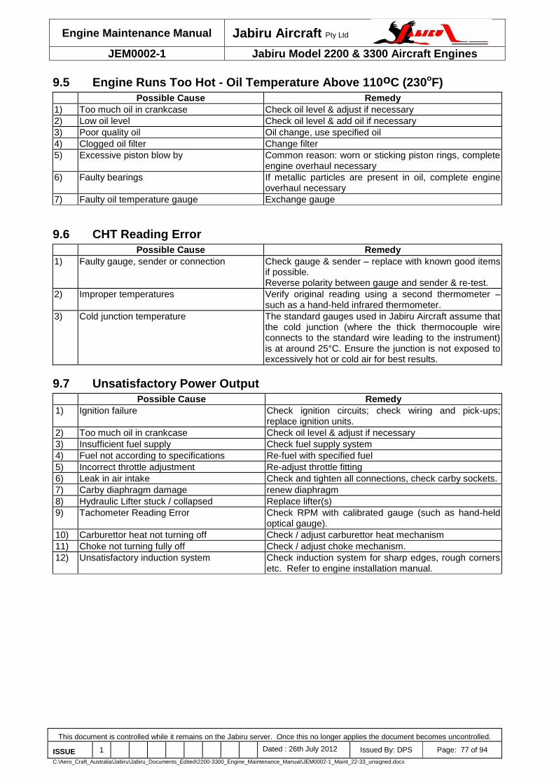
Engine Maintenance Manual Jabiru Aircraft Pty Ltd
JEM0002-1 Jabiru Model 2200 & 3300 Aircraft Engines
This document is controlled while it remains on the Jabiru server. Once this no longer applies the document becomes uncontrolled.
ISSUE 1 Dated : 26th July 2012 Issued By: DPS Page: 77 of 94
C:\Aero_Craft_Australia\Jabiru\Jabiru_Documents_Edited\2200-3300_Engine_Maintenance_Manual\JEM0002-1_Maint_22-33_unsigned.docx
9.5 Engine Runs Too Hot - Oil Temperature Above 110oC (230oF)
Possible Cause Remedy
1) Too much oil in crankcase Check oil level & adjust if necessary
2) Low oil level Check oil level & add oil if necessary
3) Poor quality oil Oil change, use specified oil
4) Clogged oil filter Change filter
5) Excessive piston blow by Common reason: worn or sticking piston rings, complete engine overhaul necessary
6) Faulty bearings If metallic particles are present in oil, complete engine overhaul necessary
7) Faulty oil temperature gauge Exchange gauge
9.6 CHT Reading Error
Possible Cause Remedy
1) Faulty gauge, sender or connection Check gauge & sender – replace with known good items if possible. Reverse polarity between gauge and sender & re-test.
2) Improper temperatures Verify original reading using a second thermometer – such as a hand-held infrared thermometer.
3) Cold junction temperature The standard gauges used in Jabiru Aircraft assume that the cold junction (where the thick thermocouple wire connects to the standard wire leading to the instrument) is at around 25°C. Ensure the junction is not exposed to excessively hot or cold air for best results.
9.7 Unsatisfactory Power Output
Possible Cause Remedy
1) Ignition failure Check ignition circuits; check wiring and pick-ups; replace ignition units.
2) Too much oil in crankcase Check oil level & adjust if necessary
3) Insufficient fuel supply Check fuel supply system
4) Fuel not according to specifications Re-fuel with specified fuel
5) Incorrect throttle adjustment Re-adjust throttle fitting
6) Leak in air intake Check and tighten all connections, check carby sockets.
7) Carby diaphragm damage renew diaphragm
8) Hydraulic Lifter stuck / collapsed Replace lifter(s)
9) Tachometer Reading Error Check RPM with calibrated gauge (such as hand-held optical gauge).
10) Carburettor heat not turning off Check / adjust carburettor heat mechanism
11) Choke not turning fully off Check / adjust choke mechanism.
12) Unsatisfactory induction system Check induction system for sharp edges, rough corners etc. Refer to engine installation manual.

Engine Maintenance Manual Jabiru Aircraft Pty Ltd
JEM0002-1 Jabiru Model 2200 & 3300 Aircraft Engines
This document is controlled while it remains on the Jabiru server. Once this no longer applies the document becomes uncontrolled.
ISSUE 1 Dated : 26th July 2012 Issued By: DPS Page: 78 of 94
C:\Aero_Craft_Australia\Jabiru\Jabiru_Documents_Edited\2200-3300_Engine_Maintenance_Manual\JEM0002-1_Maint_22-33_unsigned.docx
9.8 Low Oil Pressure
Possible Cause Remedy
1) Insufficient oil in sump Check oil level & replenish as necessary
2) High oil temperature Check engine is not over-full with oil Check installation: improper gaps or insufficient pressure head produce low airflow which can lead to elevated temperatures.
3) Faulty pressure gauge, sender or wiring Check gauge, sender & wiring. Renew as necessary.
4) Faulty crankshaft bearings Engine overhaul
5) Relief valve not sealing Inspect, replace back after cleaning. Foreign matter stuck in the valve will produce low pressure.
9.9 Oil Pressure Varying
Possible Cause Remedy
1) Low oil level Check oil level & replenish as necessary
2) Sender, gauge or connection fault Check continuity of sender wire. Check sender body is earthed to engine Check gauge – replace with known good gauge if possible. Adjust oil pressure relief valve
9.10 Engine Keeps Running with Ignition Off
Possible Cause Remedy
1) Idle speed too high Adjust to proper idle speed (900 RPM)
2) Faulty ignition switch Check switch & cables. Repair/replace as necessary
3) Overheated engine Conduct cooling run at 900 RPM
9.11 Excessive Oil Consumption
Possible Cause Remedy
1) Worn, broken or wrongly fitted piston rings Repair/engine overhaul necessary
2) Poor oil quality Oil change, use specified oil
3) Worn valve guides Repair of cylinder head necessary
4) Oil leaks Seal leaks
9.12 Oil Collector Bottle on Firewall Fills Quickly
Possible Cause Remedy
3) Worn, broken or wrongly fitted piston rings Repair/engine overhaul necessary
4) Incorrect oil grade Oil change, use specified oil
5) Worn or distorted cylinders Repair/engine overhaul necessary
6) Over-filling sump Reduce oil level in sump
7) Negative-g The Jabiru Engine is not approved for deliberate negative G operations. Strong turbulence in flight can have a similar effect: reduced RPM /speed is recommended when operating in strong turbulence.

Engine Maintenance Manual Jabiru Aircraft Pty Ltd
JEM0002-1 Jabiru Model 2200 & 3300 Aircraft Engines
This document is controlled while it remains on the Jabiru server. Once this no longer applies the document becomes uncontrolled.
ISSUE 1 Dated : 26th July 2012 Issued By: DPS Page: 79 of 94
C:\Aero_Craft_Australia\Jabiru\Jabiru_Documents_Edited\2200-3300_Engine_Maintenance_Manual\JEM0002-1_Maint_22-33_unsigned.docx
9.13 Excessive Vibration
Possible Cause Remedy
1) Propeller out of balance Balance to propeller manufacturer’s instructions
2) Propeller tip tracking out of tolerance Check / adjust tracking
3) Uneven propeller blade pitch Check / adjust blade pitch
4) Spinner out of balance Check / adjust spinner balance (see Section 8.3 or manufacturer’s instructions)
5) Unsuitable propeller Replace propeller. Quality 2-bladed fixed pitch wooden types recommended.
6) Incorrect Tuning Check / adjust carburettor
7) Engine rubbing Check engine, air ducts, exhaust, oil cooler etc are not rubbing on cowls, fuselage etc.
9.14 Knocking Under Load
Possible Cause Remedy
1) Octane rating too low. Fuel old or stale. Use fuel with higher octane rating
2) Spark plug fitted without sealing washer Ensure one sealing washer on each plug
3) Heavy carbon deposits Remove cylinder heads & in combustion chamber remove deposits. Determine oil consumption.
Notes: - Running this engine on low octane fuel will cause piston damage and in extreme cases failure
of the top ring gland or holed piston due to detonation. - Changing the engine tuning to a leaner air fuel mix can cause piston damage.

Engine Maintenance Manual Jabiru Aircraft Pty Ltd
JEM0002-1 Jabiru Model 2200 & 3300 Aircraft Engines
This document is controlled while it remains on the Jabiru server. Once this no longer applies the document becomes uncontrolled.
ISSUE 1 Dated : 26th July 2012 Issued By: DPS Page: 80 of 94
C:\Aero_Craft_Australia\Jabiru\Jabiru_Documents_Edited\2200-3300_Engine_Maintenance_Manual\JEM0002-1_Maint_22-33_unsigned.docx
9.15 Engine Hard to Start at Low Temperature – Cold Start Checklist
Possible Cause Remedy
1) Starter motor condition Check that the bushes in the starter motor bendix drive housing are in good condition. Ensure the brushes are not worn out, that the commutator is clean and all electrical connections are clean. This may require removing the heat shrink from the soldered connection on the starter motor and checking for corrosion.
2) Spark plugs Spark plugs must be within the set life and be gapped correctly. In winter spark plug gaps can be reduced as low as 0.020” to allow the plugs to fire more easily
3) High tension leads High tension leads must be in good condition. Ensure all end terminals are tight and fitting to the distributor & spark plugs correctly. If necessary adjust per Section 8.9. Don’t forget to check the plug where the ignition coils connect to the distributor cap. Note that running the engine at night with the cowls removed will make the bright arcs caused by faulty insulation, bad connections etc much more visible.
4) Distributor assembly Check that the distributor & rotor are in good condition. Check that there is no moisture inside the cap and that all the electrical terminals are clean
5) Ignition coil gaps Check that the coils have been set with the correct air gap from the flywheel magnets.
6) Air filter Check that the air filter is clean
7) Fuel filter Check that the fuel filter is clean
8) Carburettor Check that the carburettor float level is set correctly and that the carburettor is clean and in good condition. Ensure there is no debris blocking jets (including the choke jet) etc
9) Low battery charge Fit fully charged battery. The life of a Battery varies but is generally less than 4 years.
10) Operation Minimise the time spent at low RPM with high-powered devices running. At low RPM the alternator produce virtually no power – certainly not enough to run landing lights, strobe lights and avionics suites. The deficit between the power draw of these systems and the alternator output must be drawn from the battery. Excessive operation like this will drain the battery and significantly reduce the output available for cold starting the next day
11) Fly regularly Any vehicle will be harder to start if it goes a long time between outings. If the aircraft has not been flown for a few weeks then charging the battery before attempting a start is recommended. Standing also affects the quality of the fuel in the carburettor and fuel system – volatile elements in the fuel can evaporate, making it harder for the carburettor to atomise it properly
12) Starting method The recommended procedure is to hold the choke fully ON and the throttle fully OFF. The Bing carburettor uses an enrichment-type choke system (as opposed to a butterfly-type choke) which will only work properly if the throttle is fully closed. When the throttle butterfly is closed it creates a vacuum which is then used to suck fuel through the choke jet – if the throttle is not closed there is less vacuum and the choke does not work as designed. Also note that there is a tendency for the choke to spring back slightly from the ON position if the knob is released – operators are recommended to hold the knob fully ON when starting to make sure it stays properly on.
13) Idle speed Ensure that the idle RPM is set correctly. If the idle is too high the throttle butterfly will be open slightly – which will prevent the choke from working properly, as described above. Idle RPM limits are given in the engine manuals
14) Choke Jet The choke jet needs to have a bore of about 1.2mm. This gives the engine more fuel when the choke is applied, making it easier to start. New engines and aircraft have been set at this size since around February 2011, however older units will need to be checked and, if necessary, enlarged. See Figure 46
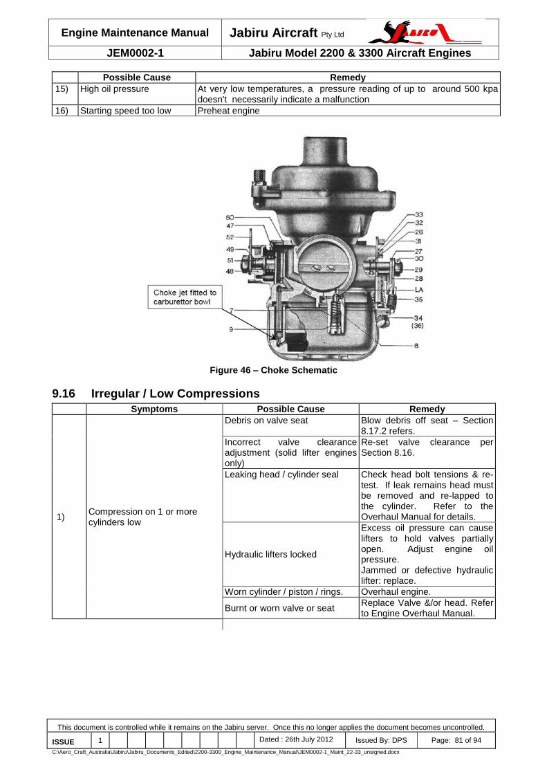
Engine Maintenance Manual Jabiru Aircraft Pty Ltd
JEM0002-1 Jabiru Model 2200 & 3300 Aircraft Engines
This document is controlled while it remains on the Jabiru server. Once this no longer applies the document becomes uncontrolled.
ISSUE 1 Dated : 26th July 2012 Issued By: DPS Page: 81 of 94
C:\Aero_Craft_Australia\Jabiru\Jabiru_Documents_Edited\2200-3300_Engine_Maintenance_Manual\JEM0002-1_Maint_22-33_unsigned.docx
Possible Cause Remedy
15) High oil pressure At very low temperatures, a pressure reading of up to around 500 kpa doesn't necessarily indicate a malfunction
16) Starting speed too low Preheat engine
Figure 46 – Choke Schematic
9.16 Irregular / Low Compressions
Symptoms Possible Cause Remedy
1) Compression on 1 or more cylinders low
Debris on valve seat Blow debris off seat – Section 8.17.2 refers.
Incorrect valve clearance adjustment (solid lifter engines only)
Re-set valve clearance per Section 8.16.
Leaking head / cylinder seal Check head bolt tensions & re-test. If leak remains head must be removed and re-lapped to the cylinder. Refer to the Overhaul Manual for details.
Hydraulic lifters locked
Excess oil pressure can cause lifters to hold valves partially open. Adjust engine oil pressure. Jammed or defective hydraulic lifter: replace.
Worn cylinder / piston / rings. Overhaul engine.
Burnt or worn valve or seat Replace Valve &/or head. Refer to Engine Overhaul Manual.

Engine Maintenance Manual Jabiru Aircraft Pty Ltd
JEM0002-1 Jabiru Model 2200 & 3300 Aircraft Engines
This document is controlled while it remains on the Jabiru server. Once this no longer applies the document becomes uncontrolled.
ISSUE 1 Dated : 26th July 2012 Issued By: DPS Page: 82 of 94
C:\Aero_Craft_Australia\Jabiru\Jabiru_Documents_Edited\2200-3300_Engine_Maintenance_Manual\JEM0002-1_Maint_22-33_unsigned.docx
9.17 Hydraulic Valve Lifters
Symptoms Possible Cause Remedy
1) Engine noisy, “tapping” at idle
“Soft” lifter(s) due to lifter fault Replace lifter(s)
“Soft” lifter(s) due to low oil pressure
See Low Oil Pressure section above.
“Soft” lifter(s) due to air in lifter
Run engine. Up to 15 minutes running may be required to completely expel air from the lifter. OR Remove lifter and manually fill with oil.
2) Reduced engine power
Soft or stuck hydraulic lifter(s) Replace lifter(s)
“Soft” lifter(s) due to low oil pressure
See Low Oil Pressure section above.
Lifters “pumping up” holding valves open
Reduce operating oil pressure (within limits)
Replace lifter(s)
3) Excess metal in oil filter Cam / Lifter damage Inspect lifter and cam working surfaces. Replace if damaged.
Notes: - Refer to Section 8.19 for additional details on hydraulic lifter maintenance requirements.

Engine Maintenance Manual Jabiru Aircraft Pty Ltd
JEM0002-1 Jabiru Model 2200 & 3300 Aircraft Engines
This document is controlled while it remains on the Jabiru server. Once this no longer applies the document becomes uncontrolled.
ISSUE 1 Dated : 26th July 2012 Issued By: DPS Page: 83 of 94
C:\Aero_Craft_Australia\Jabiru\Jabiru_Documents_Edited\2200-3300_Engine_Maintenance_Manual\JEM0002-1_Maint_22-33_unsigned.docx
10 Airworthiness Limitations Section The Airworthiness Limitations Section is CASA Approved. There are no Airworthiness Limitations pertaining to the Jabiru 2200C engine Signed: ....................................... Date: ........................................... Dinh Nguyen Delegate of the Authority

Engine Maintenance Manual Jabiru Aircraft Pty Ltd
JEM0002-1 Jabiru Model 2200 & 3300 Aircraft Engines
This document is controlled while it remains on the Jabiru server. Once this no longer applies the document becomes uncontrolled.
ISSUE 1 Dated : 26th July 2012 Issued By: DPS Page: 84 of 94
C:\Aero_Craft_Australia\Jabiru\Jabiru_Documents_Edited\2200-3300_Engine_Maintenance_Manual\JEM0002-1_Maint_22-33_unsigned.docx
11 Maintenance Worksheets
11.1 25-Hour Worksheet Table 17 – 25-Hour Inspection Worksheet
25-Hour inspection carried out in accordance with Jabiru Engine Maintenance Manual JEM0002. Engine & Engine Compartment per Section 7.8:
Inspection of Engine & Compartment – Pre Cleaning, Intake and exhaust systems, Electrical wiring Engine-Driven Fuel pump, Starter, solenoid and electrical connections, Oil Collector Bottle on Firewall Oil & filter change: Oil Type:
Notes: Carried out by:
11.2 50-Hour Worksheet Table 18 – 50-Hour Inspection Worksheet
50-Hour inspection carried out in accordance with Jabiru Engine Maintenance Manual JEM0002. Propeller per Section 7.7: Spinner, Spinner Mount Plates, Spinner Screws,
Propeller, Prop Tracking, Propeller bolts/nuts – Tension, Spinner Tracking. Engine & Engine Compartment per Section 7.8:
Engine Pre-Inspection Test Run Warm idle RPM: Full Power RPM: RPM drop on L Mag: RPM drop on R Mag: Idle Oil Pressure: Full Power oil Pressure: Notes:
Engine Cowlings, Inspection of Engine & Compartment – Pre Cleaning, Carburetor air filter – check & replace if necessary Engine baffles and air ducts, Cylinders, Crankcase & front crankcase seal, Fuel hoses, lines and fittings, Intake and exhaust systems, Ignition harness, distributor caps & rotors, Check Spark Plug Gaps, Compression leak-down check:
#1 80
#2 80
#3 80
#4 80
#5 80
#6 80
Electrical wiring Engine-Driven Fuel pump, Engine controls and linkages, Engine mounts, mount structure, Safety Wires, Starter, solenoid and electrical connections, Coils and electrical connections Carburettor heat system, Throttle and linkage, Carburettor Oil system tubes and hoses, Firewall, Oil Collector Bottle on Firewall Exhaust system – including muffler, Cylinder Head bolt tension, Valve Clearance Oil & filter change: Oil Type: , SCAT hose condition
Fuel System per Section 7.9: Replace fuel filter(s), Drain valves Carburettor bowl, Engine Post-Inspection Test Run
Warm idle RPM: Full Power RPM: RPM drop on L Mag: RPM drop on R Mag: Idle Oil Pressure: Full Power oil Pressure: Notes: Carried out by:

Engine Maintenance Manual Jabiru Aircraft Pty Ltd
JEM0002-1 Jabiru Model 2200 & 3300 Aircraft Engines
This document is controlled while it remains on the Jabiru server. Once this no longer applies the document becomes uncontrolled.
ISSUE 1 Dated : 26th July 2012 Issued By: DPS Page: 85 of 94
C:\Aero_Craft_Australia\Jabiru\Jabiru_Documents_Edited\2200-3300_Engine_Maintenance_Manual\JEM0002-1_Maint_22-33_unsigned.docx
11.3 100-Hour Worksheet Table 19 – 100-Hour Inspection Worksheet
100-Hour inspection carried out in accordance with Jabiru Engine Maintenance Manual JEM0002. Propeller per Section 7.7: Spinner, Spinner Mount Plates, Spinner Screws,
Propeller, Prop Tracking, Propeller bolts/nuts – Tension, Spinner Tracking. Engine & Engine Compartment per Section 7.8:
Engine Pre-Inspection Test Run Warm idle RPM: Full Power RPM: RPM drop on L Mag: RPM drop on R Mag: Idle Oil Pressure: Full Power oil Pressure: Notes:
Engine Cowlings, Inspection of Engine & Compartment – Pre Cleaning, Clean Engine & Compartment, Inspection of Engine Compartment – Clean, Carburetor air filter – replace, Engine baffles and air ducts, Cylinders, Crankcase & front crankcase seal, Fuel hoses, lines and fittings, Intake and exhaust systems, Ignition harness, distributor caps & rotors, Replace Spark Plugs, Check Spark Plug Gaps, Compression leak-down check:
#1 80
#2 80
#3 80
#4 80
#5 80
#6 80
Electrical wiring Engine-Driven Fuel pump, Engine controls and linkages, Engine mounts, mount structure, Safety Wires, Starter, solenoid and electrical connections, Coils and electrical connections Carburettor heat system, Throttle and linkage, Carburettor Oil system tubes and hoses, Firewall, Oil Collector Bottle on Firewall Exhaust system – including muffler, Cylinder Head bolt tension, Valve Clearance Hydraulic Lifter & Rocker Inspection, Oil & filter change: Oil Type: , SCAT hose condition
Fuel System per Section 7.9: Replace fuel filter(s), Drain valves Carburettor bowl, Electronic fuel boost pump and fittings Fuel lines, taps and connectors, Fire sleeves
Engine Post-Inspection Test Run
Warm idle RPM: Full Power RPM: RPM drop on L Mag: RPM drop on R Mag: Idle Oil Pressure: Full Power oil Pressure: Notes: Carried out by:

Engine Maintenance Manual Jabiru Aircraft Pty Ltd
JEM0002-1 Jabiru Model 2200 & 3300 Aircraft Engines
This document is controlled while it remains on the Jabiru server. Once this no longer applies the document becomes uncontrolled.
ISSUE 1 Dated : 26th July 2012 Issued By: DPS Page: 86 of 94
C:\Aero_Craft_Australia\Jabiru\Jabiru_Documents_Edited\2200-3300_Engine_Maintenance_Manual\JEM0002-1_Maint_22-33_unsigned.docx
11.4 200-Hour Worksheet Table 20 – 200-Hour Inspection Worksheet
200-Hour inspection carried out in accordance with Jabiru Engine Maintenance Manual JEM0002. Propeller per Section 7.7: Spinner, Spinner Mount Plates, Spinner Screws,
Propeller, Prop Tracking, Propeller bolts/nuts – Tension, Spinner Tracking. Engine & Engine Compartment per Section 7.8:
Engine Pre-Inspection Test Run Warm idle RPM: Full Power RPM: RPM drop on L Mag: RPM drop on R Mag: Idle Oil Pressure: Full Power oil Pressure: Notes:
Engine Cowlings, Inspection of Engine & Compartment – Pre Cleaning, Clean Engine & Compartment, Inspection of Engine Compartment – Clean, Check flywheel screw tensions, Carburetor air filter – replace Engine baffles and air ducts, Cylinders, Crankcase & front crankcase seal, Fuel hoses, lines and fittings, Intake and exhaust systems, Ignition harness, distributor caps & rotors, Replace Spark Plugs, Check Spark Plug Gaps, Compression leak-down check:
#1 80
#2 80
#3 80
#4 80
#5 80
#6 80
Electrical wiring Engine-Driven Fuel pump, Engine controls and linkages, Engine mounts, mount structure, Safety Wires, Starter, solenoid and electrical connections, Coils and electrical connections Carburettor heat system, Throttle and linkage, Carburettor Oil system tubes and hoses, Firewall, Oil Collector Bottle on Firewall Exhaust system – including muffler, Cylinder Head bolt tension, Valve Clearance Hydraulic Lifter & Rocker Inspection, Oil & filter change: Oil Type: , SCAT hose condition
Fuel System per Section 7.9: Replace fuel filter(s), Drain valves Carburettor bowl, Electronic fuel boost pump and fittings Fuel lines, taps and connectors, Fire sleeves
Engine Post-Inspection Test Run
Warm idle RPM: Full Power RPM: RPM drop on L Mag: RPM drop on R Mag: Idle Oil Pressure: Full Power oil Pressure: Notes: Carried out by:
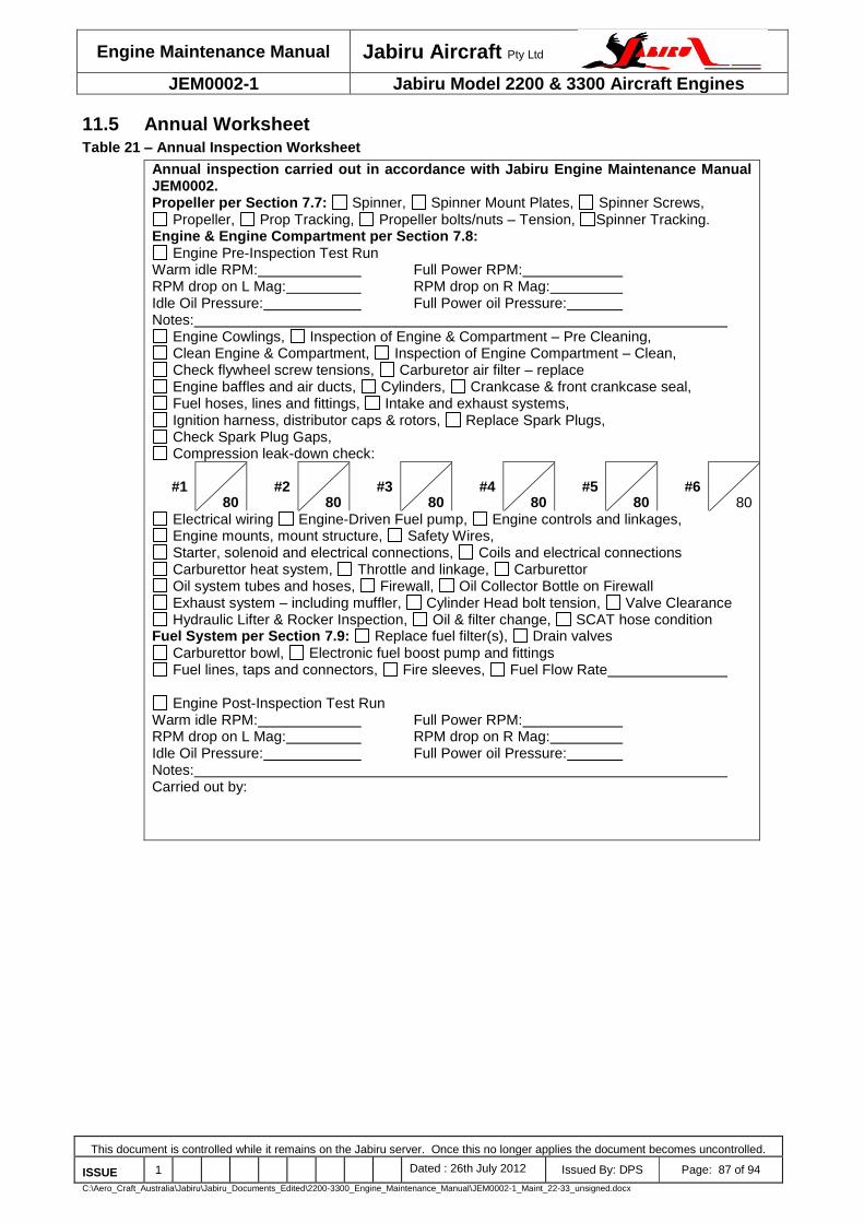
Engine Maintenance Manual Jabiru Aircraft Pty Ltd
JEM0002-1 Jabiru Model 2200 & 3300 Aircraft Engines
This document is controlled while it remains on the Jabiru server. Once this no longer applies the document becomes uncontrolled.
ISSUE 1 Dated : 26th July 2012 Issued By: DPS Page: 87 of 94
C:\Aero_Craft_Australia\Jabiru\Jabiru_Documents_Edited\2200-3300_Engine_Maintenance_Manual\JEM0002-1_Maint_22-33_unsigned.docx
11.5 Annual Worksheet Table 21 – Annual Inspection Worksheet
Annual inspection carried out in accordance with Jabiru Engine Maintenance Manual JEM0002. Propeller per Section 7.7: Spinner, Spinner Mount Plates, Spinner Screws,
Propeller, Prop Tracking, Propeller bolts/nuts – Tension, Spinner Tracking. Engine & Engine Compartment per Section 7.8:
Engine Pre-Inspection Test Run Warm idle RPM: Full Power RPM: RPM drop on L Mag: RPM drop on R Mag: Idle Oil Pressure: Full Power oil Pressure: Notes:
Engine Cowlings, Inspection of Engine & Compartment – Pre Cleaning, Clean Engine & Compartment, Inspection of Engine Compartment – Clean, Check flywheel screw tensions, Carburetor air filter – replace Engine baffles and air ducts, Cylinders, Crankcase & front crankcase seal, Fuel hoses, lines and fittings, Intake and exhaust systems, Ignition harness, distributor caps & rotors, Replace Spark Plugs, Check Spark Plug Gaps, Compression leak-down check:
#1 80
#2 80
#3 80
#4 80
#5 80
#6 80
Electrical wiring Engine-Driven Fuel pump, Engine controls and linkages, Engine mounts, mount structure, Safety Wires, Starter, solenoid and electrical connections, Coils and electrical connections Carburettor heat system, Throttle and linkage, Carburettor Oil system tubes and hoses, Firewall, Oil Collector Bottle on Firewall Exhaust system – including muffler, Cylinder Head bolt tension, Valve Clearance Hydraulic Lifter & Rocker Inspection, Oil & filter change, SCAT hose condition
Fuel System per Section 7.9: Replace fuel filter(s), Drain valves Carburettor bowl, Electronic fuel boost pump and fittings Fuel lines, taps and connectors, Fire sleeves, Fuel Flow Rate
Engine Post-Inspection Test Run
Warm idle RPM: Full Power RPM: RPM drop on L Mag: RPM drop on R Mag: Idle Oil Pressure: Full Power oil Pressure: Notes: Carried out by:

Engine Maintenance Manual Jabiru Aircraft Pty Ltd
JEM0002-1 Jabiru Model 2200 & 3300 Aircraft Engines
This document is controlled while it remains on the Jabiru server. Once this no longer applies the document becomes uncontrolled.
ISSUE 1 Dated : 26th July 2012 Issued By: DPS Page: 88 of 94
C:\Aero_Craft_Australia\Jabiru\Jabiru_Documents_Edited\2200-3300_Engine_Maintenance_Manual\JEM0002-1_Maint_22-33_unsigned.docx
12 New Engine – Jabiru’s Limited, Express Warranty
Jabiru Aircraft Pty Ltd New Jabiru Aircraft Engines (“the engine”) are covered by Jabiru’s Limited, Express Warranty (“the Warranty”) as set forth below. I. Parties to Whom this Warranty is Given
This Limited, Express Warranty is given to the person who is entitled to possession of the engine whether as owner, lessee or otherwise (“owner”). This Warranty is given in addition to all rights conferred on that person by law of the governing state, and/or in place of any laws or regulations on the terms set forth below. II. Scope of the Warranty
Jabiru Aircraft Pty Ltd. (“JABIRU”) warrants that its new and unused engine has no defects in material and/or workmanship for the period and under the conditions described in this Warranty. The owner of the engine agrees that the terms and conditions of this Warranty are exclusive and expressly disclosed, and that the owner accepted them at the time of purchase of the engine. III. Coverage Period and Conditions of Coverage
JABIRU warrants that it will make good without charge, any defect (except as provided for in Section IV, Exclusions, below), which appears in the engine, provided that: 1. Notice of the defect has been provided in writing to JABIRU:
(a) Before the engine has operated a total of 200 hours, or (b) Within twelve (12) months of the date of delivery of the engine to the first retail
purchaser. Whichever comes first; and,
2. The owner must register the engine by mailing a warranty registration card to JABIRU or its authorized JABIRU Distributor/Dealer, within 30 days of purchase (an engine registration card is included with each engine; contact JABIRU Distributor/Dealer with any questions); and,
3. The engine has been delivered to JABIRU, its authorized Distributor/Dealer, or such other service facility as advised in writing by JABIRU; and,
4. The engine has been installed in an aircraft type in accordance with a JABIRU approved installation system; and,
5. The engine has been updated in accordance with JABIRU Service Bulletins before operation; 6. The engine has been stored in accordance with the Engine Preservation instructions in the
JABIRU Engine Maintenance manual; and, 7. For any and all engines installed in airframes other than the airframes manufactured by
JABIRU, the owner has provided JABIRU with: a) evidence that the cooling system of the cowling produces pressure deferential test results consistent with the requirements of the JABIRU installation manual; and, b) delivery of the log book that reflects engine parameters during any and all initial flights.
This Warranty applies only to engines which have been inspected and maintained in accordance with the instructions for continued airworthiness, including compliance with all applicable service documents issued by JABIRU. Performance of required inspections and maintenance must be documented by appropriate logbook entries and the logbook must accompany any engine being submitted for warranty consideration. JABIRU reserves the right to make warranty coverage contingent upon proof of proper inspection and maintenance. Warranty repairs do not extend the original Limited, Express Warranty.

Engine Maintenance Manual Jabiru Aircraft Pty Ltd
JEM0002-1 Jabiru Model 2200 & 3300 Aircraft Engines
This document is controlled while it remains on the Jabiru server. Once this no longer applies the document becomes uncontrolled.
ISSUE 1 Dated : 26th July 2012 Issued By: DPS Page: 89 of 94
C:\Aero_Craft_Australia\Jabiru\Jabiru_Documents_Edited\2200-3300_Engine_Maintenance_Manual\JEM0002-1_Maint_22-33_unsigned.docx
The duration and any other terms of this Warranty are subject to the governing law of the owner’s state. JABIRU reserves the right to improve or modify its engines from time to time without assuming any obligation to modify its engines manufactured previously. The owner must comply fully with all conditions of this Section III for the Warranty coverage to have full force and effect. Non-compliance with the conditions of this Section III constitutes a waiver of any and all benefits of this Limited, Express Warranty. IV. Exclusions The Warranty is applicable as long as JABIRU has determined that the alleged defect complained of is one of workmanship and is not caused by: 1. Normal wear and tear or service items (such as spark plugs, filters, hoses, etc.); 2. Alteration, modification, removal, service or repair performed by anyone party not
authorized in writing by JABIRU, or any modification of the engine from its original configuration;
3. Any misuse or abuse of engine, such as storage, installation, operation, usage or maintenance outside the approved JABIRU Flight Manual, or Maintenance and Operation Manual, service documents, airworthiness directives, bulletins, instructions, and recommendations, or by neglect;
4. Improper installation, including overheating; 5. Operation of the engine after it is known to be defective; 6. Installation and/or fitting of accessories, parts, components. or other items not marketed by
JABIRU; 7. Cold seizures, piston scuffing, and any damage resulting from lack of lubrication; 8. Ingestion of foreign objects, dirt inside or outside of the engine, corrosion, electrolysis,
sulphidation, ingestion of water, ice or any other damage due to the operating environment; 9. Atmospheric fallout or flood, hail, salt, wind; 10. Failure to carry out proper maintenance service; 11. Use of incorrect types and/or grade of fuel, oil, or lubricants; 12. The use of parts of the engine having exceeded any limitation or recommended limitation
established by the manufacturer; 13. The use of the engine or spare parts from which the part number or serial number has been
removed or modified; 14. Fire, lightning strike, neglect, negligence, accident, incident, deliberate act, misuse, theft,
casualty or any other factor beyond JABIRU’s control; or, 15. The use of any engine oil or fuel additives or oil stabilizers.
This Warranty does not cover normal maintenance service such as tune-ups, adjustments, inspections, engine or component overhaul, replacement of air and oil filters, spark plugs, etc. Further, this Warranty applies only to the engines that are manufactured or supplied by JABIRU. JABIRU has no responsibility for the failure of any engine or part which it does not manufacture or supply, or for any damage resulting from any such failure. V. DISCLAIMERS
THIS LIMITED, EXPRESS WARRANTY IS EXCLUSIVE, EXPRESSLY GIVEN, AND ACCEPTED IN LIEU OF ANY AND OTHER GUARANTIES OR WARRANTIES, EXPRESS OR IMPLIED, INCLUDING WITHOUT LIMITATION ANY WARRANTY OF MERCHANTABILITY OR FITNESS FOR A PARTICULAR PURPOSE, OR OTHER WARRANTIES IMPLIED IN LAW. THERE ARE NO WARRANTIES WHICH EXTEND BEYOND THAT WHICH IS DESCRIBED IN JABIRU’S LIMITED, EXPRESS WARRANTY. FOR ANY OTHER OBLIGATION AND/OR LIABILTIY OF JABIRU AND/OR ITS AFFILIATES, WHETHER FOR NEGLIGENCE, STRICT LIABILITY, OR BREACH OF WARRANTY, THE OWNER’S REMEDIES SHALL BE LIMITED TO THE REMEDIES PROVIDED FOR IN THIS WARRANTY. TO THE EXTENT THAT THE IMPLIED

Engine Maintenance Manual Jabiru Aircraft Pty Ltd
JEM0002-1 Jabiru Model 2200 & 3300 Aircraft Engines
This document is controlled while it remains on the Jabiru server. Once this no longer applies the document becomes uncontrolled.
ISSUE 1 Dated : 26th July 2012 Issued By: DPS Page: 90 of 94
C:\Aero_Craft_Australia\Jabiru\Jabiru_Documents_Edited\2200-3300_Engine_Maintenance_Manual\JEM0002-1_Maint_22-33_unsigned.docx
WARRANTIES CANNOT BE DISCLAIMED, THEY ARE LIMITED IN DURATION TO THE LIFE OF THIS LIMITED EXRESS WARRANTY. THIS LIMITED EXPRESS WARRANTY IS A WARRANTY TO REPAIR OR REPLACE AND NOT A WARRANTY OF THE CONDITION OR FUTURE PERFORMANCE OF THE ENGINE OR ITS PARTS. IN ADDITION, THIS WARRANTY DOES NOT COVER INCIDENTAL OR CONSEQUENTIAL DAMAGES, SUCH AS LOSS OF REVENUE, RENTAL COSTS, OR MISSED OPPORTUNITIES, NO MATTER HOW ARISING, INCLUDING, BUT NOT LIMITED TO, THOSE ARISING OUT OF ANY DEFECT IN ANY ENGINE OR ITS COMPONENT, ARISING OUT OF THE FAILURE OF ANY ENGINE OR ITS COMPONENT TO OPERATE PROPERLY, OR ARISING OUT OF ANY BREACH OF THIS LIMITED WARRANTY. JABIRU MAKES NO REPRESENTATION THAT THIS ENGINE IS SUITABLE FOR INSTALLATION IN ANY PARTICULAR AIRCRAFT, OTHER THAN AIRCRAFT MANUFACTURED BY JABIRU, AND THE RESPONSIBILITY TO DETERMINE SUITABILITY RESTS WITH THE OWNER. SOME STATES DO NOT ALLOW THE DISCLAIMERS AND/OR LIMITATIONS IDENTIFIED IN THIS WARRANTY. THEREFORE, THE ABOVE-STATED DISCLAIMERS AND/OR LIMITATIONS MAY BE INAPPLICABLE. THIS WARRANTY GIVES THE OWNER SPECIFIC LEGAL RIGHTS, AND THE OWNER MAY ALSO HAVE OTHER RIGHTS WHICH MAY VARY FROM STATE TO STATE. If the governing law of a state disallows the disclaimers, limitations and exclusions set forth in this Warranty, then only those specific disclaimers that are not allowed will be disregarded and deemed to be stricken, and all other provisions and limitations of this warranty will remain effective and enforceable. No JABIRU Distributor/Dealer or any other person or entity is authorised or permitted to give or make any statement assertion or undertaking in relation to the quality, performance, characteristics, descriptions or fitness for any purpose of any JABIRU product or in connection with the supply of any JABIRU product, which is at variance with any written statement assertion or undertaking on any of these subjects given or made by JABIRU in its published sales literature, and the company does not accept any such unauthorised action. SPECIAL NOTE TO AUSTRALIAN OWNERS: The above-stated disclaimer of liability for consequential damages does not apply to owners who both: 1) fall within the definition of a “consumer” under the Australian Consumer Law; and, 2) acquire the engine in Australia, provided that the acquired engine also falls within the definition of “goods” covered under the Australian Consumer Law, and provided that all other conditions of the applicability of the Australian Consumer Law are satisfied. In addition, for any such engines defined in this Special Note, this Warranty does not exclude and/or affect the warranties and/or guarantees that are set forth in the Australian Consumer Law. VI. Available Remedy
JABIRU (or as otherwise decided by JABIRU) will make the defect good by repair or, at the option of JABIRU, by replacement. The repair or replacement (if opted by JABIRU) shall be the sole and exclusive remedy available under this Warranty, and will be the absolute limit on JABIRU’s or any

Engine Maintenance Manual Jabiru Aircraft Pty Ltd
JEM0002-1 Jabiru Model 2200 & 3300 Aircraft Engines
This document is controlled while it remains on the Jabiru server. Once this no longer applies the document becomes uncontrolled.
ISSUE 1 Dated : 26th July 2012 Issued By: DPS Page: 91 of 94
C:\Aero_Craft_Australia\Jabiru\Jabiru_Documents_Edited\2200-3300_Engine_Maintenance_Manual\JEM0002-1_Maint_22-33_unsigned.docx
of its authorized representatives’ liability whether based upon equity, contract or tort (including, but not limited to, negligence, strict liability, breach of contract, or breach of warranty) arising out of: (1) this Warranty; (2) the design, manufacture, delivery, sale, repair, replacement or any use of the engine and/or its parts; or, (3) the furnishing of any such service. Unless specifically required by the law of a governing state, JABIRU does not cover the costs of freight, removal, and reinstallation of the engine. If the law of a governing state specifically requires that the costs of freight, removal, and reinstallation be covered, then under the conditions set forth in Sections VIII, IX, and X below, JABIRU will cover said costs should repairs be required during the warranty period, provided, however, that the repairs are not due to the conditions described in Section IV, Exclusions, above. SOME STATES MAY PROVIDE OWNERS WITH REMEDIES IN ADDITION TO THOSE SPECIFIED IN THIS SECTION. THIS WARRANTY GIVES THE OWNER SPECIFIC LEGAL RIGHTS AND REMEDIES, AND THE OWNER MAY ALSO HAVE ADDITIONAL REMEDIES WHICH MAY VARY FROM STATE TO STATE. VII. Repair or Replacement of Parts
As a part of its Limited, Express Warranty, JABIRU warrants in respect of JABIRU parts and accessories required as replacement parts, that it will make good by repair or at its option by replacement any defect occurring in any such JABIRU parts and accessories within twelve (12) months from the date of acquisition. Normal wear and tear is excluded. This Limited, Express Warranty does not cover those parts listed in Section IV, Exclusions, above and is subject to the same general exclusions. VIII. Labor Costs For any coverage period specified in Section III above, JABIRU will absorb certain labor costs incurred in connection with the repair or replacement of parts covered by this Warranty, provided, however, that said parts must be delivered directly to JABIRU (Airport Drive, Hinkler Airport, Bundaberg West, Queensland, Australia) and JABIRU itself performs the repairs. For JABIRU to cover labor costs in connection with the repair or replacement of parts that belong to non-Australian international owners, said parts must be delivered to JABIRU official Dealers/Distributors as directed in writing by JABIRU. JABIRU will compensate International JABIRU Dealers/Distributors for the allowed labor costs at the rate that JABIRU charges for any similar job. IX. Troubleshooting Costs For the first TWELVE (12) CONSECUTIVE MONTHS of the coverage or the coverage period set forth in Section III of this Warranty above, whichever is shorter, JABIRU will pay for certain troubleshooting costs in connection with determining the need for any repair or replacement covered by this Warranty, when performed by, or coordinated through, JABIRU or an authorized JABIRU Distributor/Dealer, and where a defect is identified that results in a warranty claim. The amount of troubleshooting costs allowed will be in accordance with the latest revision of JABIRU’s limited warranty labor allowance for any applicable part or component, which is made available to JABIRU or its authorized Distributor/Dealer. In no event will the Trouble Shooting Costs exceed fifteen percent (15%) of the Labor Costs allowed by JABIRU for such repairs or replacements. No Troubleshooting Costs will be covered where the need for repair or replacement under warranty is identified in the course of overhaul, routine maintenance, or on the basis of an obvious nonconformity, or if the damage is not one covered by this limited Warranty. No Troubleshooting Costs will be reimbursed if the need for a repair covered by this warranty was identified by someone other than a person or entity approved in writing by JABIRU.

Engine Maintenance Manual Jabiru Aircraft Pty Ltd
JEM0002-1 Jabiru Model 2200 & 3300 Aircraft Engines
This document is controlled while it remains on the Jabiru server. Once this no longer applies the document becomes uncontrolled.
ISSUE 1 Dated : 26th July 2012 Issued By: DPS Page: 92 of 94
C:\Aero_Craft_Australia\Jabiru\Jabiru_Documents_Edited\2200-3300_Engine_Maintenance_Manual\JEM0002-1_Maint_22-33_unsigned.docx
For any engine to be delivered to JABIRU (Australia), it is the owner’s sole responsibility to clean the engine from including, but not limited to, soil, debris, sand, gravel, plant matter, seeds, and/or any other foreign matter. It is also the owner’s sole responsibility to completely drain the engine from oil, fuel, and/or any other liquids. Further, for any engine to be delivered to JABIRU (Australia), it is the owner’s sole responsibility to comply with any and all cleaning requirements imposed by Australian Customs and Border Protection Services (“Australian Customs”) and Australian Quarantine and Inspection Services (“AQIS”). JABIRU will not be responsible for costs of cleaning the engine, any other related fines, penalties, and/or any other costs that result from the owner’s failure to comply with the requirements imposed by the Australian Customs and/or AQIS. It is the owner’s sole responsibility to pay any such costs, fines, and/or penalties imposed by the Australian Customs and/or AQIS. For any engine to be delivered to a JABIRU Dealer/Distributor located outside Australia, it is the owner’s sole responsibility to clean the engine from including, but not limited to, soil, debris, sand, gravel, plant matter, seeds, and/or any other foreign matter. It is also the owner’s sole responsibility to completely drain the engine from oil, fuel, and/or any other liquids. Further, for any engine to be delivered to a JABIRU Dealer/Distributor located outside Australia, it is the owner’s sole responsibility to comply with any and all cleaning requirements imposed by Customs, Border Protection, Quarantine and Inspection Authorities of the state where the JABIRU Dealer/Distributor is located. Neither JABIRU nor its Dealer/Distributor will be responsible for costs of cleaning the engine, any other related fines, penalties, and/or any other costs that result from the owner’s failure to comply with the requirements imposed by Customs, Border Protection, Quarantine and Inspection Authorities of the state where the JABIRU Dealer/Distributor is located. It is the owner’s sole responsibility to pay any such costs, fines, and/or penalties. X. Additional Conditions – Owners’ Actions to Obtain Coverage The Owner must notify JABIRU or its authorized Distributor/Dealer, in writing, within fourteen (14) days from discovery of a condition that the owner believes is resulting from a defect in material or workmanship. Any defects which are not reported within fourteen (14) days shall not qualify for any claims under this Warranty. Failure to do so will result in denial of coverage under this Warranty. Note that the notification period is subject to the applicable national or local legislation. The owner must provide reasonable access to the engine, its parts and accessories, and a reasonable opportunity for JABIRU or its authorized Distributor/Dealer to repair it. Also, if requested, the owner must also present proof of purchase. If you cannot locate a JABIRU Distributor/Dealer or if you have any additional questions regarding this Warranty, please visit our website at http://www.jabiru.net.au/. XI. No Defect Found
If a duly reported alleged defect cannot be confirmed as such by JABIRU or its authorized distributors and/or dealers and therefore no repair or replacement will be necessary, the owner shall bear all costs accrued in connection with the examination and transportation of the alleged defective item. XII. Availability of Service and Parts after Warranty
JABIRU maintains a substantial stock of spare parts and operates a Service Exchange Programme in respect to some components. Every endeavour is made to ensure that JABIRU carries adequate

Engine Maintenance Manual Jabiru Aircraft Pty Ltd
JEM0002-1 Jabiru Model 2200 & 3300 Aircraft Engines
This document is controlled while it remains on the Jabiru server. Once this no longer applies the document becomes uncontrolled.
ISSUE 1 Dated : 26th July 2012 Issued By: DPS Page: 93 of 94
C:\Aero_Craft_Australia\Jabiru\Jabiru_Documents_Edited\2200-3300_Engine_Maintenance_Manual\JEM0002-1_Maint_22-33_unsigned.docx
stocks of service parts and is equipped to provide satisfactory service, but JABIRU does not make any promise that after the expiration of the Limited, Express Warranty such parts or service will be available, or available at any specific location or at any particular time. XIII. Changes and modification of this Warranty
JABIRU reserves the right to modify this warranty at any time in writing. However, any such modification will not change the terms of the warranty applicable to the engines sold while this warranty is in effect. XIV. Engine Transfer If the ownership of the engine is transferred during the warranty coverage period, this Warranty and limitations of liability and disclaimers shall also be transferred and will be valid for the remaining coverage period, provided that: a) JABIRU or its authorized Distributor/Dealer promptly receives proof that the former owner agreed to the ownership transfer; b) JABIRU or its authorized Distributor/Dealer promptly receives the new owner’s name and contact details; and, c) the conditions set forth in Section III above have been fully complied with. Signed By: ___________________________Date:______________________ Name (Printed): __________________________________________________ Address (Printed): __________________________________________________

Engine Maintenance Manual Jabiru Aircraft Pty Ltd
JEM0002-1 Jabiru Model 2200 & 3300 Aircraft Engines
This document is controlled while it remains on the Jabiru server. Once this no longer applies the document becomes uncontrolled.
ISSUE 1 Dated : 26th July 2012 Issued By: DPS Page: 94 of 94
C:\Aero_Craft_Australia\Jabiru\Jabiru_Documents_Edited\2200-3300_Engine_Maintenance_Manual\JEM0002-1_Maint_22-33_unsigned.docx
13 Jabiru’s Limited, Express Warranty: Claim Form FROM:__________________________________DATE:____________ ENGINE PARTS: AIRFRAME PARTS: ENGINE NUMBER: AIRFRAME KIT NUMBER:__________ PART NUMBER: TOTAL HOURS:__________________ OWNER: PREVIOUS OWNER:_______________ PART DESCRIPTION: CLAIM: FAULTY GOODS RETURNED: YES COURIER Co. REF NO:__________ NO ALL GOODS THAT ARE BOXED AND HAVE TO PASS THROUGH CUSTOMS HAVE TO BE CLEANED AND FREE FROM CONTAMINATION WITH A STATEMENT ATTACHED SPECIFING HOW THEY WERE CLEANED AND THAT THEY ARE FREE OF DIRT AND GRASS SEEDS. IF THEY ARE NOT CLEANED TO CUSTOMS SATISFACTION AN EXTRA CLEANING CHARGE WILL APPLY. IF THIS CLAIM FORM IS NOT COMPLETELY AND CORRECTLY COMPLETED WARRANTY MAY BE REFUSED.
OFFICE USE ONLY
APPROVED NOT APPROVED
REASON
PRINTED NAME:
SIGNED: DATED: