MAINTENANCE MANUAL - hardingeservice.com -0009500-0333.pdf · MAINTENANCE MANUAL CONQUEST® T51 and...
252
MAINTENANCE MANUAL CONQUEST ® T51 and T65 Series CNC Lathes EQUIPPED WITH THE GE FANUC 18T CONTROL Revised: February, 1999 Manual No. M-333 Litho in U.S.A. Part No. M -0009500-0333 June, 1998 TP2141
Transcript of MAINTENANCE MANUAL - hardingeservice.com -0009500-0333.pdf · MAINTENANCE MANUAL CONQUEST® T51 and...

MAINTENANCE MANUAL
CONQUEST® T51 and T65 SeriesCNC Lathes
EQUIPPED WITH THEGE FANUC 18T CONTROL
Revised: February, 1999
Manual No. M-333 Litho in U.S.A.Part No. M -0009500-0333 June, 1998
TP2141

- NOTICE -Damage resulting from misuse, negligence, or accident is not covered by theHardinge Machine warranty.
Information in this manual is subject to change without notice.
This manual covers the routine maintenance of the Hardinge CONQUEST®
T51 and T65 series CNC Lathes equipped with the GE Fanuc 18T control andabsolute encoders.
In no event will Hardinge Inc. be responsible for indirect or consequentialdamage resulting from the use or application of the information in this manual.
Reproduction of this manual in whole or in part, without written permission ofHardinge Inc., is prohibited.
CONVENTIONS USED IN THIS MANUAL
- WARNINGS -Warnings must be followed carefully to avoid the possibility of personal injuryand damage to the machine, tooling, or workpiece.
- CAUTIONS -Cautions must be followed carefully to avoid the possibility of damage to the ma-chine, tooling, or workpiece.
- NOTES -Notes contain supplemental information.
Hardinge Inc.Elmira, N.Y. 14902-1507 U.S.A.
www.hardinge.com
© 1998, Hardinge Inc. M-333

READ THIS INFORMATION CAREFULLY BEFORE STARTING OPERATION,MAINTENANCE, OR REPAIR ON CONQUEST® T51 AND CONQUEST T65 SERIESCNC LATHES.
The technicians who use this manual should have a general knowledge of machine maintenanceand repair. This general knowledge coupled with the following manual will greatly reduce or eliminatedowntime of the Conquest machine.
When machine maintenance is performed by persons not familiar with the operation of this equip-ment, the Operator’s Manual (M-332) must be consulted when instructions require that the machinebe run.
- WARNINGS -Occupational Safety and Health Administration (OSHA) Hazard CommunicationStandard 1910.1200, effective September 23, 1987, and various state “employeeright-to-know laws” require that information regarding chemicals used with thismachine be supplied to you. The list of chemicals appears in manual M-179, theMaterial Safety Data Sheets (MSDS’s). Refer to the applicable section of theMSDS’s supplied with your machine when handling, storing, or disposing ofchemicals. Store MSDS’s of other chemicals used with this Hardinge machine inthe same packet with manual M-179.
Any bar feed system to be used with these machines, must be approved byHardinge Inc.
HARDINGE SAFETY RECOMMENDATIONSYour Hardinge machine is designed and built for maximum ease and safety of operation. Because
some previously accepted shop practices may not reflect current safety regulations and procedures,they should be re-examined to insure compliance with the current safety and health standards.
Hardinge, Inc. recommends that all shop supervisors, maintenance personnel, and machine tooloperators be advised of the importance of safe maintenance, setup, and operation of all equipment.Our recommendations are described below. READ THESE SAFETY RECOMMENDATIONS BE-FORE PROCEEDING ANY FURTHER.
READ THE APPROPRIATE MANUAL OR INSTRUCTIONS before attempting operation,programming, or maintenance of the machine. Make certain that you understand all instruc-tions.
CONSULT YOUR SUPERVISOR when in doubt as to the correct way to do a job.
DON’T OPERATE EQUIPMENT unless proper maintenance has been regularly performedand the equipment is known to be in good working order.
WARNING and INSTRUCTION TAGS are mounted on the machine for your safety and in-formation. Do not remove them.
DON’T ALTER THE MACHINE to bypass any interlock, overload, disconnect switch, orother safety device.
(continued on next page)
M-333 i

DON’T ALLOW the operation or repair of equipment by untrained personnel.
DON’T OPERATE ANY MACHINE while wearing rings, watches, jewelry, loose clothing,and/or neckties. Long hair must be contained by a net or shop cap for safety.
WEAR SAFETY GLASSES AND PROPER FOOT PROTECTION at all times. Wear a res-pirator, helmet, gloves, and ear muffs or plugs when necessary.
DON’T OPERATE EQUIPMENT if unusual or excessive heat, noise, smoke, or vibrationoccurs. Report any excessive or unusual conditions as well as any damaged parts to yoursupervisor.
ALLOW ONLY AUTHORIZED PERSONNEL to have access to enclosures containing elec-trical equipment.
DISCONNECT MAIN ELECTRICAL POWER before attempting repair or maintenance.
DON’T REACH into any control or power case area unless electrical power is OFF.
MAKE CERTAIN that the equipment is properly grounded. Consult and comply with theNational Electric Code and all local codes.
DON’T TOUCH ELECTRICAL EQUIPMENT when hands are wet or when standing on awet surface.
REPLACE BLOWN FUSES with fuses of the same size and type as originally furnished.
ASCERTAIN AND CORRECT the cause of any shutdown before restarting the machine.
KEEP THE AREA AROUND THE MACHINE well lighted and dry.
KEEP CHEMICALS AND FLAMMABLE MATERIAL away from operating equipment.
HAVE THE CORRECT TYPE OF FIRE EXTINGUISHER handy when machining combusti-ble material and keep the chips clear of the work area.
DON’T USE a toxic or flammable substance as a solvent cleaner or coolant.
INSPECT ALL SAFETY DEVICES AND GUARDS to make certain that they are in goodcondition and are functioning properly.
MAKE CERTAIN THAT PROPER GUARDS are in place and that all doors and covers arein place and secured before starting a machining cycle.
DON’T OPEN GUARDS while any machine component is in motion. Make certain that allpeople in the area are clear of the machine when opening the guard door.
MAKE SURE that chucks, closers, fixture plates, and all other spindle-mounted work-hold-ing devices are properly mounted.
MAKE CERTAIN that all tooling is secured in position before starting the machine.
ii M-333
DON’T USE worn or defective hand tools. Use the proper size and type tool for the job be-ing performed.
USE CAUTION around exposed mechanisms and tooling especially when setting up. Becareful of sharp edges on tools.
USE ONLY a soft-faced hammer on turret tools and fixtures.
MAKE CERTAIN that all tool mounting surfaces are clean before mounting tools.
DON’T USE worn or broken tooling on the machine.
INSPECT ALL CHUCKING DEVICES daily to make certain that they are in good operatingcondition. Replace any defective chuck before operating the machine.
ANY ATTACHMENT, TOOL, OR MACHINE MODIFICATION not obtained from HardingeInc., must be reviewed by a qualified safety engineer before installation.
USE MAXIMUM ALLOWABLE gripping pressure on the chuck. Consider the weight, shape,and balance of the workpiece.
USE LIGHTER THAN NORMAL feedrates and depth of cut when machining a workpiecediameter that is larger than the gripping diameter.
DON’T EXCEED the rated capacity of the machine.
DON’T LEAVE tools, workpieces or other loose items where they can come in contact witha moving component of the machine.
REMOVE ANY LOOSE PARTS OR TOOLS from the work area. Always clear the machineand work area of tools and parts especially after work has been completed by maintenancepersonnel.
REMOVE CHUCK WRENCHES before starting the machine.
CHECK THE SETUP, TOOLING, AND SECURE THE WORKPIECE if the machine hasbeen turned OFF for any length of time.
CHECK THE LUBRICATION AND COOLANT LEVELS and the status of control indicatorlights before operating the machine.
KNOW where all EMERGENCY STOP pushbuttons are located.
MAKE CERTAIN THAT PROPER FUNCTIONS are programmed and that all controls areset in the desired modes before pressing the Cycle Start pushbutton.
CHECK THE TURRET POSITION before pressing the Cycle Start pushbutton.
DRY CYCLE a new setup to check for programming errors.
DON’T ADJUST tooling or coolant hoses while the machine is running.
KEEP CLEAR of any “pinch point” and any potentially hazardous situation.(continued on next page)
M-333 iii
DON’T LEAVE the machine unattended while it is operating.
DON’T REMOVE OR LOAD workpieces while any part of the machine is in motion.
BE CAREFUL of sharp edges when handling newly machined workpieces.
DON’T CHECK the finish or dimension of a workpiece near a running spindle or movingslide.
DON’T JOG SPINDLE in either direction when checking threads with a thread gage.
DON’T ATTEMPT to brake or slow the machine with hands or any makeshift device.
DON’T REMOVE CHIPS with hands. Make certain that all machine movement has stoppedand then use a hook or similar device to remove chips and shavings.
DON’T CLEAN the machine with an air hose.
KEEP TOTE PANS a safe distance from machine. Don’t overfill the tote pans.
DON’T LET STOCK project past the back end of the collet closer or machine spindle with-out being adequately contained and properly supported.
When a bar feed system is used, make certain that it is properly ALIGNED with the spin-dle. If the bar feed is a floor-mounted type, it must be securely fastened to floor.
When a bar feed system is used, follow the bar feed manufacturer’s guidelines. For perfor-mance and safe application - SIZE and USE feed tube bushings, pushers, and spindle lin-ers according to the bar feed manufacturer’s information.
Unless otherwise noted, all operating and maintenance procedures are to be performed byone person. To avoid injury to yourself and others, be sure that all personnel are clear ofthe machine when opening or closing the coolant guard door and any access covers.
FOR YOUR PROTECTION - WORK SAFELY
iv M-333

Table of Contents
Hardinge Safety Recommendations . . . . . . . . . . . . . . . . . . . . . . . . i
CHAPTER 1 - INSTALLATIONMachine Serial Number. . . . . . . . . . . . . . . . . . . . . . . . . . . . . . 1-1CNC Control Serial Number. . . . . . . . . . . . . . . . . . . . . . . . . . . . 1-1Machine Foundation . . . . . . . . . . . . . . . . . . . . . . . . . . . . . . . 1-3Cleaning the Machine . . . . . . . . . . . . . . . . . . . . . . . . . . . . . . 1-8Pneumatic (Air) Connection . . . . . . . . . . . . . . . . . . . . . . . . . . . . 1-8Power Connection . . . . . . . . . . . . . . . . . . . . . . . . . . . . . . . . 1-9
Power Requirements for CONQUEST® T51 and T65 machines. . . . . . . . . . 1-9To make the electrical connection . . . . . . . . . . . . . . . . . . . . . . . 1-10Earth Ground . . . . . . . . . . . . . . . . . . . . . . . . . . . . . . . . . 1-11System Grounding . . . . . . . . . . . . . . . . . . . . . . . . . . . . . . 1-12
Cutting Fluid (Coolant) . . . . . . . . . . . . . . . . . . . . . . . . . . . . . . 1-13Sub-Spindle Draw Tube Wiper Installation . . . . . . . . . . . . . . . . . . . . . 1-14Non-Metallic Materials Typically Found in Hardinge Machine Construction . . . . . . 1-15
CHAPTER 2 - POWER-UP PROCEDUREIntroduction . . . . . . . . . . . . . . . . . . . . . . . . . . . . . . . . . . . 2-1Basic Machine Power-Up . . . . . . . . . . . . . . . . . . . . . . . . . . . . . 2-1Power-Down and Lock Out Procedure . . . . . . . . . . . . . . . . . . . . . . . 2-2Resetting Overtravel . . . . . . . . . . . . . . . . . . . . . . . . . . . . . . . 2-2Hour Run Meter . . . . . . . . . . . . . . . . . . . . . . . . . . . . . . . . . 2-2Turret Zero Return . . . . . . . . . . . . . . . . . . . . . . . . . . . . . . . . 2-3Control Status Information . . . . . . . . . . . . . . . . . . . . . . . . . . . . 2-4Power On with Power Case and/or Control Case Door Open . . . . . . . . . . . . 2-6
To power up the machine with control case door open . . . . . . . . . . . . . 2-6To open control case door when the machine is ON. . . . . . . . . . . . . . . 2-7To open power case door(s) . . . . . . . . . . . . . . . . . . . . . . . . . . 2-7To power up the machine when power case door is open . . . . . . . . . . . . 2-7
CHAPTER 3 - AIR FACILITIESIntroduction . . . . . . . . . . . . . . . . . . . . . . . . . . . . . . . . . . . 3-1Power-Down Procedure . . . . . . . . . . . . . . . . . . . . . . . . . . . . . 3-1Air Control Assembly . . . . . . . . . . . . . . . . . . . . . . . . . . . . . . . 3-2Drain the Filter/Regulator and Coalescing Filter Bowls . . . . . . . . . . . . . . . 3-2Replace the Filters . . . . . . . . . . . . . . . . . . . . . . . . . . . . . . . . 3-3Replace the Air Control Assembly Components . . . . . . . . . . . . . . . . . . 3-3Replace the Pressure Switch . . . . . . . . . . . . . . . . . . . . . . . . . . . 3-4Replace or Clean the Manifold . . . . . . . . . . . . . . . . . . . . . . . . . . 3-5Solenoid Valves . . . . . . . . . . . . . . . . . . . . . . . . . . . . . . . . . 3-5Air Blast Option . . . . . . . . . . . . . . . . . . . . . . . . . . . . . . . . . 3-6
M-333 v
CHAPTER 4 - COOLANT FACILITIESIntroduction . . . . . . . . . . . . . . . . . . . . . . . . . . . . . . . . . . . 4-1Cutting Fluid (Coolant) . . . . . . . . . . . . . . . . . . . . . . . . . . . . . . 4-1
Water-Based Coolants . . . . . . . . . . . . . . . . . . . . . . . . . . . . 4-1To prepare the coolant system . . . . . . . . . . . . . . . . . . . . . . . . . 4-2
Care and Maintenance. . . . . . . . . . . . . . . . . . . . . . . . . . . . . . 4-3Power-Down Procedure . . . . . . . . . . . . . . . . . . . . . . . . . . . . 4-3Concentration. . . . . . . . . . . . . . . . . . . . . . . . . . . . . . . . . 4-3pH . . . . . . . . . . . . . . . . . . . . . . . . . . . . . . . . . . . . . . 4-4Water Quality . . . . . . . . . . . . . . . . . . . . . . . . . . . . . . . . . 4-4
Removing Chips and Shavings . . . . . . . . . . . . . . . . . . . . . . . . . . 4-4Cleaning the Reservoir and Filters. . . . . . . . . . . . . . . . . . . . . . . . . 4-5Replacing the Headwall Adjustable Hoses or In-line Valves . . . . . . . . . . . . . 4-7Replacing the Coolant Pump . . . . . . . . . . . . . . . . . . . . . . . . . . . 4-7Turret Coolant Facilities . . . . . . . . . . . . . . . . . . . . . . . . . . . . . 4-9Headwall Coolant Valve . . . . . . . . . . . . . . . . . . . . . . . . . . . . . 4-10
To replace the coolant valve . . . . . . . . . . . . . . . . . . . . . . . . . . 4-10To replace the coolant valve solenoid switch . . . . . . . . . . . . . . . . . . 4-11To replace the air solenoid valve on the air panel . . . . . . . . . . . . . . . . 4-11
Coolant Catcher . . . . . . . . . . . . . . . . . . . . . . . . . . . . . . . . . 4-12High Pressure Coolant System Option . . . . . . . . . . . . . . . . . . . . . . . 4-13Thru-Spindle Coolant Option . . . . . . . . . . . . . . . . . . . . . . . . . . . 4-14
To remove the thru-spindle coolant shaft from the spindle . . . . . . . . . . . . 4-15To mount the thru-spindle coolant shaft in the spindle . . . . . . . . . . . . . . 4-15
Rear Discharge Coolant System . . . . . . . . . . . . . . . . . . . . . . . . . 4-15Chip removal procedure . . . . . . . . . . . . . . . . . . . . . . . . . . . . 4-16
Adjustable Hoses/In-Line Valves . . . . . . . . . . . . . . . . . . . . . . . . . 4-16
CHAPTER 5 - HYDRAULIC MODULEIntroduction . . . . . . . . . . . . . . . . . . . . . . . . . . . . . . . . . . . 5-1Power-Down Procedure . . . . . . . . . . . . . . . . . . . . . . . . . . . . . 5-1Hydraulic Reservoir . . . . . . . . . . . . . . . . . . . . . . . . . . . . . . . 5-2
To fill the hydraulic tank . . . . . . . . . . . . . . . . . . . . . . . . . . . . 5-2Clean and Refill the Hydraulic Tank . . . . . . . . . . . . . . . . . . . . . . . . 5-2
To clean and refill the tank . . . . . . . . . . . . . . . . . . . . . . . . . . 5-2Hydraulic Filter . . . . . . . . . . . . . . . . . . . . . . . . . . . . . . . . . . 5-3
To replace the filter element . . . . . . . . . . . . . . . . . . . . . . . . . . 5-3Hydraulic Manifold . . . . . . . . . . . . . . . . . . . . . . . . . . . . . . . . 5-4
To replace a pressure gauge . . . . . . . . . . . . . . . . . . . . . . . . . 5-4To replace the solenoid valve(s) . . . . . . . . . . . . . . . . . . . . . . . . 5-4To replace the molded LED connector(s) . . . . . . . . . . . . . . . . . . . . 5-5To replace the switches . . . . . . . . . . . . . . . . . . . . . . . . . . . . 5-5To replace the coil and cartridge valves . . . . . . . . . . . . . . . . . . . . 5-6To replace the mechanical valves (pressure regulators) . . . . . . . . . . . . . 5-7
Accumulator . . . . . . . . . . . . . . . . . . . . . . . . . . . . . . . . . . . 5-7To adjust the accumulator precharge . . . . . . . . . . . . . . . . . . . . . . 5-7
vi M-333
CHAPTER 6 - LUBRICATIONIntroduction . . . . . . . . . . . . . . . . . . . . . . . . . . . . . . . . . . . 6-1Lubricator Refill . . . . . . . . . . . . . . . . . . . . . . . . . . . . . . . . . 6-2
To fill the lubricator tank . . . . . . . . . . . . . . . . . . . . . . . . . . . . 6-2To correct the low lubricator condition . . . . . . . . . . . . . . . . . . . . . 6-3
TRABON® Lubricator Reservoir and Divider Valves (Feeders) . . . . . . . . . . . . 6-3To change the system filter element . . . . . . . . . . . . . . . . . . . . . . 6-3To prefill/ purge (prime) the TRABON lubrication system of air before operation . . 6-3To replace master divider valve and/or secondary feeders . . . . . . . . . . . . 6-5
Replace the Lubricator . . . . . . . . . . . . . . . . . . . . . . . . . . . . . . 6-6To clean the oil reservoir . . . . . . . . . . . . . . . . . . . . . . . . . . . 6-7
Clean Tramp Oil Line. . . . . . . . . . . . . . . . . . . . . . . . . . . . . . . 6-7To clean the tramp oil opening . . . . . . . . . . . . . . . . . . . . . . . . . 6-7
CHAPTER 7 - HEADSTOCK and SPINDLE DRIVEIntroduction . . . . . . . . . . . . . . . . . . . . . . . . . . . . . . . . . . . 7-1Power-Down Procedure . . . . . . . . . . . . . . . . . . . . . . . . . . . . . 7-1Spindle Draw Tube Plug . . . . . . . . . . . . . . . . . . . . . . . . . . . . . 7-2Spindle Drive Belt Adjustment. . . . . . . . . . . . . . . . . . . . . . . . . . . 7-2Spindle Drive Belt Replacement . . . . . . . . . . . . . . . . . . . . . . . . . . 7-3Spindle Encoder Timing Belt Adjustment. . . . . . . . . . . . . . . . . . . . . . 7-5Spindle Encoder Replacement . . . . . . . . . . . . . . . . . . . . . . . . . . 7-5Spindle Encoder Timing Belt Replacement . . . . . . . . . . . . . . . . . . . . . 7-7Spindle Brake Replacement. . . . . . . . . . . . . . . . . . . . . . . . . . . . 7-10Headstock Alignment . . . . . . . . . . . . . . . . . . . . . . . . . . . . . . . 7-11LVDT (Linear Variable Differential Transducer) . . . . . . . . . . . . . . . . . . . 7-152-1/2 Degree Spindle Orient Option . . . . . . . . . . . . . . . . . . . . . . . . 7-18Programmable C-Axis Option . . . . . . . . . . . . . . . . . . . . . . . . . . . 7-22
CHAPTER 8 - COLLET CLOSERIntroduction . . . . . . . . . . . . . . . . . . . . . . . . . . . . . . . . . . . 8-1Free Spindle . . . . . . . . . . . . . . . . . . . . . . . . . . . . . . . . . . . 8-1Power-Down Procedure . . . . . . . . . . . . . . . . . . . . . . . . . . . . . 8-2Chucking Force . . . . . . . . . . . . . . . . . . . . . . . . . . . . . . . . . 8-2Automatic Collet Closer Operation. . . . . . . . . . . . . . . . . . . . . . . . . 8-3Manual Collet Closer Operation . . . . . . . . . . . . . . . . . . . . . . . . . . 8-3Internal Chucking . . . . . . . . . . . . . . . . . . . . . . . . . . . . . . . . 8-3Remove and Install the Collet Closer . . . . . . . . . . . . . . . . . . . . . . . 8-4Clean the Spindle Draw Tube . . . . . . . . . . . . . . . . . . . . . . . . . . . 8-8Removable Spindle Draw Tube Nut . . . . . . . . . . . . . . . . . . . . . . . . 8-10
M-333 vii

CHAPTER 9 - RESET TORQUE LIMITERS and ZERO RETURN SETUPSIntroduction . . . . . . . . . . . . . . . . . . . . . . . . . . . . . . . . . . . 9-1Torque Limiter . . . . . . . . . . . . . . . . . . . . . . . . . . . . . . . . . . 9-1
To Reset the Z-Axis Torque Limiter . . . . . . . . . . . . . . . . . . . . . . 9-2To Reset the X-Axis Torque Limiter . . . . . . . . . . . . . . . . . . . . . . 9-2To Reset the Lower Axis (Y Axis, tailstock, end-working turret, or sub-spindle) . . 9-3
Z-Axis Zero Return Setup. . . . . . . . . . . . . . . . . . . . . . . . . . . . . 9-3X-Axis Zero Return Setup. . . . . . . . . . . . . . . . . . . . . . . . . . . . . 9-6Lower Axis (Y-Axis, LA) Zero Return Setup . . . . . . . . . . . . . . . . . . . . 9-8Turret Home Setup . . . . . . . . . . . . . . . . . . . . . . . . . . . . . . . . 9-10
CHAPTER 10 - AXIS DRIVE MOTORSIntroduction . . . . . . . . . . . . . . . . . . . . . . . . . . . . . . . . . . . 10-1Carriage Drive Motor Replacement . . . . . . . . . . . . . . . . . . . . . . . . 10-1Cross Slide Drive Motor . . . . . . . . . . . . . . . . . . . . . . . . . . . . . 10-4
To replace the cross slide drive motor . . . . . . . . . . . . . . . . . . . . . 10-4
CHAPTER 11 - TURRETIntroduction . . . . . . . . . . . . . . . . . . . . . . . . . . . . . . . . . . . 11-1Power-Down Procedure . . . . . . . . . . . . . . . . . . . . . . . . . . . . . 11-1Turret Unclamp Conditions . . . . . . . . . . . . . . . . . . . . . . . . . . . . 11-1
To clear the unclamp condition or to re-establish the top plate sequence . . . . . 11-1To reset the turret. . . . . . . . . . . . . . . . . . . . . . . . . . . . . . . 11-2
Turret Alignment . . . . . . . . . . . . . . . . . . . . . . . . . . . . . . . . . 11-3Turret Clamp/Unclamp (20PRS) Proximity Switch . . . . . . . . . . . . . . . . . 11-5Turret Hydraulic Valve Block . . . . . . . . . . . . . . . . . . . . . . . . . . . 11-6
To adjust the top plate “cushion” . . . . . . . . . . . . . . . . . . . . . . . . 11-6To replace the turret hydraulic valve block . . . . . . . . . . . . . . . . . . . 11-7
Live Tooling Attachment Maintenance . . . . . . . . . . . . . . . . . . . . . . . 11-8Live Tooling Drive Motor and Belt . . . . . . . . . . . . . . . . . . . . . . . . . 11-9Turret Top Plate . . . . . . . . . . . . . . . . . . . . . . . . . . . . . . . . . 11-11
CHAPTER 12 - TAILSTOCKSIntroduction . . . . . . . . . . . . . . . . . . . . . . . . . . . . . . . . . . . 12-1Programmable Positioning Tailstock . . . . . . . . . . . . . . . . . . . . . . . . 12-1Travel Specifications . . . . . . . . . . . . . . . . . . . . . . . . . . . . . . . 12-2Turning the Tailstock Function ON or OFF . . . . . . . . . . . . . . . . . . . . . 12-3Tailstock Positions . . . . . . . . . . . . . . . . . . . . . . . . . . . . . . . . 12-3
Fixed HOME Position (Retract) . . . . . . . . . . . . . . . . . . . . . . . . 12-3Adjustable HOME Position (Retract) . . . . . . . . . . . . . . . . . . . . . . 12-3Forward Position (Extend) . . . . . . . . . . . . . . . . . . . . . . . . . . . 12-4
Machine Power-Down . . . . . . . . . . . . . . . . . . . . . . . . . . . . . . 12-4Live Center and Eccentric Bushing . . . . . . . . . . . . . . . . . . . . . . . . 12-4Tailstock Alignment. . . . . . . . . . . . . . . . . . . . . . . . . . . . . . . . 12-5Tailstock Home (14LS), Adjustable Home (15LS), andRapid-To-Feed (Decel)(16LS) Limit Switches. . . . . . . . . . . . . . . . . . . . 12-8
viii M-333Revised: February, 1999
Tailstock Switches - Adjustment and Replacement . . . . . . . . . . . . . . . . . 12-8To set the adjustable Home and rapid-to-feed dogs . . . . . . . . . . . . . . . 12-8To adjust the solid stop for tailstock extend . . . . . . . . . . . . . . . . . . . 12-9To replace the switch block . . . . . . . . . . . . . . . . . . . . . . . . . . 12-9
Tailstock Components on the Hydraulic Manifold . . . . . . . . . . . . . . . . . . 12-10Tailstock Hydraulic Cylinder Replacement . . . . . . . . . . . . . . . . . . . . . 12-10
To replace the hydraulic cylinder . . . . . . . . . . . . . . . . . . . . . . . . 12-10Gib Adjustment . . . . . . . . . . . . . . . . . . . . . . . . . . . . . . . . . 12-12
To adjust the tailstock gib . . . . . . . . . . . . . . . . . . . . . . . . . . . 12-12
MANUALLY POSITIONED TAILSTOCK (CONQUEST® T65-L Lathe Only) . . . . . . 12-13Introduction . . . . . . . . . . . . . . . . . . . . . . . . . . . . . . . . . . . 12-13Tailstock Positioning . . . . . . . . . . . . . . . . . . . . . . . . . . . . . . . 12-14Quill Movement . . . . . . . . . . . . . . . . . . . . . . . . . . . . . . . . . 12-15
To initiate manual quill movement . . . . . . . . . . . . . . . . . . . . . . . 12-15To stop manual quill movement . . . . . . . . . . . . . . . . . . . . . . . . 12-15
Hydraulic Pressure Adjustment . . . . . . . . . . . . . . . . . . . . . . . . . . 12-16Quill Lubrication . . . . . . . . . . . . . . . . . . . . . . . . . . . . . . . . . 12-17
To lubricate the tailstock quill . . . . . . . . . . . . . . . . . . . . . . . . . 12-17Tailstock Alignment. . . . . . . . . . . . . . . . . . . . . . . . . . . . . . . . 12-18
To re-align the tailstock . . . . . . . . . . . . . . . . . . . . . . . . . . . . 12-18Tailstock Air Lubricator . . . . . . . . . . . . . . . . . . . . . . . . . . . . . . 12-19
To activate the “air lift” . . . . . . . . . . . . . . . . . . . . . . . . . . . . 12-19To add oil to the air lubricator . . . . . . . . . . . . . . . . . . . . . . . . . 12-20To set the “air lift” air pressure . . . . . . . . . . . . . . . . . . . . . . . . . 12-20
CHAPTER 13 - END-WORKING TURRETIntroduction . . . . . . . . . . . . . . . . . . . . . . . . . . . . . . . . . . . 13-1Power-Down Procedure . . . . . . . . . . . . . . . . . . . . . . . . . . . . . 13-1Turret Unclamp Conditions . . . . . . . . . . . . . . . . . . . . . . . . . . . . 13-2
To clear the unclamp condition or to re-establish the top plate sequence . . . . . 13-2Zero Return (Reference Home) Procedures . . . . . . . . . . . . . . . . . . . . 13-2Turret Alignment . . . . . . . . . . . . . . . . . . . . . . . . . . . . . . . . . 13-3
To re-align the turret to the spindle centerline . . . . . . . . . . . . . . . . . . 13-3Index Motor Drive Belt . . . . . . . . . . . . . . . . . . . . . . . . . . . . . . 13-4
To adjust/replace the index motor . . . . . . . . . . . . . . . . . . . . . . . 13-4LA Turret Clamp/Unclamp (26PRS) Proximity Switch . . . . . . . . . . . . . . . . 13-5
To replace and adjust the switch . . . . . . . . . . . . . . . . . . . . . . . . 13-5Turret Lubrication . . . . . . . . . . . . . . . . . . . . . . . . . . . . . . . . 13-7
To check the lube level or fill the LA turret with oil. . . . . . . . . . . . . . . . 13-7To change the oil in the turret . . . . . . . . . . . . . . . . . . . . . . . . . 13-7
M-333 ix
CHAPTER 14 - SUB-SPINDLEIntroduction . . . . . . . . . . . . . . . . . . . . . . . . . . . . . . . . . . . 14-1Overview . . . . . . . . . . . . . . . . . . . . . . . . . . . . . . . . . . . . 14-1Operation . . . . . . . . . . . . . . . . . . . . . . . . . . . . . . . . . . . . 14-1Main Guard Door Safety Interlock . . . . . . . . . . . . . . . . . . . . . . . . . 14-2Free Spindle . . . . . . . . . . . . . . . . . . . . . . . . . . . . . . . . . . . 14-4Hydraulic Force Against Workpiece . . . . . . . . . . . . . . . . . . . . . . . . 14-4Sub-Spindle Collet Closer. . . . . . . . . . . . . . . . . . . . . . . . . . . . . 14-5Basic Machine Power-Down Procedure . . . . . . . . . . . . . . . . . . . . . . 14-5Alignment . . . . . . . . . . . . . . . . . . . . . . . . . . . . . . . . . . . . 14-6
To re-align the hydraulic cylinder driven sub-spindle . . . . . . . . . . . . . . . 14-6To re-align the ball screw driven sub-spindle . . . . . . . . . . . . . . . . . . 14-8
Sub-Spindle Collet Closer and Rotary Union AssemblyCleaning and/or Replacement . . . . . . . . . . . . . . . . . . . . . . . . . . . 14-9
To remove the collet closer/rotary union assembly from the sub-spindle . . . . . 14-10To replace the collet closer and rotary union assembly . . . . . . . . . . . . . 14-11
Spindle Drive Motor Replacement . . . . . . . . . . . . . . . . . . . . . . . . . 14-12To remove the sub-spindle drive motor . . . . . . . . . . . . . . . . . . . . . 14-12To remount the sub-spindle drive motor . . . . . . . . . . . . . . . . . . . . 14-13To synchronize the sub-spindle with the main spindle . . . . . . . . . . . . . . 14-13
Sub-Spindle Air Blast . . . . . . . . . . . . . . . . . . . . . . . . . . . . . . . 14-16To clear the chips . . . . . . . . . . . . . . . . . . . . . . . . . . . . . . . 14-16To clean the draw tube wiper . . . . . . . . . . . . . . . . . . . . . . . . . 14-16To adjust the sub-spindle air flow . . . . . . . . . . . . . . . . . . . . . . . 14-17
Sub-Spindle Collet Closer Hydraulic Manifold . . . . . . . . . . . . . . . . . . . 14-18To replace pressure gauge “A”. . . . . . . . . . . . . . . . . . . . . . . . . 14-18To replace solenoid valve(s) “B” . . . . . . . . . . . . . . . . . . . . . . . . 14-18To replace the molded LED connector(s) . . . . . . . . . . . . . . . . . . . . 14-19To replace the mechanical valve (pressure regulator) . . . . . . . . . . . . . . 14-19
Ball Screw Driven Sub-Spindle Drive Motor/Drive Belt . . . . . . . . . . . . . . . 14-20To remove the sub-spindle drive belt and drive motor . . . . . . . . . . . . . . 14-20To remount the sub-spindle drive motor and drive belt . . . . . . . . . . . . . . 14-20To set the fine Home position . . . . . . . . . . . . . . . . . . . . . . . . . 14-21
SUB-SPINDLE PART CATCHER . . . . . . . . . . . . . . . . . . . . . . . . . 14-23Lubrication. . . . . . . . . . . . . . . . . . . . . . . . . . . . . . . . . . . . 14-23
To lubricate slide rails “J”, Figure 14.20. . . . . . . . . . . . . . . . . . . . . 14-24To lubricate pivot bracket pin “M”, Figure 14.21 . . . . . . . . . . . . . . . . . 14-25
Sub-Spindle Parts Catcher Switches, Valves, and Cylinders. . . . . . . . . . . . . 14-25Roller Limit Switches - Midpoint (24LS) and Unload Part (23LS). . . . . . . . . . . 14-25
To replace the sub-spindle part catcher midpoint and unload part limit switches . . 14-26Solenoid Valves . . . . . . . . . . . . . . . . . . . . . . . . . . . . . . . . . 14-27
To replace a sub-spindle part catcher solenoid valve . . . . . . . . . . . . . . 14-27Pressure Switch . . . . . . . . . . . . . . . . . . . . . . . . . . . . . . . . . 14-28
To replace the arm retract pressure switch . . . . . . . . . . . . . . . . . . . 14-28
x M-333

CHAPTER 15 - FANSIntroduction . . . . . . . . . . . . . . . . . . . . . . . . . . . . . . . . . . . 15-1
Power-Down Procedure . . . . . . . . . . . . . . . . . . . . . . . . . . . . 15-1Input/Output (I/O) Case Air Fan . . . . . . . . . . . . . . . . . . . . . . . . . . 15-1
To replace the I/O case fan . . . . . . . . . . . . . . . . . . . . . . . . . . 15-1Power Case Fans . . . . . . . . . . . . . . . . . . . . . . . . . . . . . . . . 15-2
To replace a power case heat exchanger fan . . . . . . . . . . . . . . . . . . 15-2To replace the fan for the panel heat exchanger (plenum) inside the power case . 15-3
Clean Fan Air Filters . . . . . . . . . . . . . . . . . . . . . . . . . . . . . . . 15-4To clean the fan air filters . . . . . . . . . . . . . . . . . . . . . . . . . . . 15-4
CONQUEST® T51SP Machine Headstock Fan . . . . . . . . . . . . . . . . . . . 15-5To replace the headstock cooling fan. . . . . . . . . . . . . . . . . . . . . . 15-5
Hydraulic Heat Exchanger Fan . . . . . . . . . . . . . . . . . . . . . . . . . . 15-6To replace the hydraulic heat exchange fan. . . . . . . . . . . . . . . . . . . 15-6
Hydraulic Axis Driven Sub-Spindle Option Fan . . . . . . . . . . . . . . . . . . . 15-7To replace the sub-spindle fan . . . . . . . . . . . . . . . . . . . . . . . . . 15-7
CHAPTER 16 - MISCELLANEOUSControl Battery Unit(s) . . . . . . . . . . . . . . . . . . . . . . . . . . . . . . 16-1
To change the battery . . . . . . . . . . . . . . . . . . . . . . . . . . . . . 16-1Worklight . . . . . . . . . . . . . . . . . . . . . . . . . . . . . . . . . . . . 16-2
To replace the lamp and/or starter . . . . . . . . . . . . . . . . . . . . . . . 16-2To replace the worklight ballast . . . . . . . . . . . . . . . . . . . . . . . . 16-3
Turn Options ON Or OFF . . . . . . . . . . . . . . . . . . . . . . . . . . . . . 16-4Tool Touch Probe . . . . . . . . . . . . . . . . . . . . . . . . . . . . . . . . 16-5Part Catcher . . . . . . . . . . . . . . . . . . . . . . . . . . . . . . . . . . . 16-6Lubrication. . . . . . . . . . . . . . . . . . . . . . . . . . . . . . . . . . . . 16-6
To lubricate the slide rails . . . . . . . . . . . . . . . . . . . . . . . . . . . 16-7To lubricate the part pan bushing . . . . . . . . . . . . . . . . . . . . . . . 16-7
Midpoint (23PRS) and Fixed Home (6PRS) Proximity Switches . . . . . . . . . . . 16-8To adjust the midpoint proximity switch (23PRS) . . . . . . . . . . . . . . . . 16-8To adjust the fixed Home proximity switch (6PRS) . . . . . . . . . . . . . . . 16-9To replace and adjust the switches. . . . . . . . . . . . . . . . . . . . . . . 16-10
Extend (2A Sol) and Retract (2B Sol) Solenoid Valves . . . . . . . . . . . . . . . 16-12To replace a part catcher solenoid valve . . . . . . . . . . . . . . . . . . . . 16-12
APPENDIX ONE - PREVENTIVE MAINTENANCE SCHEDULEIntroduction . . . . . . . . . . . . . . . . . . . . . . . . . . . . . . . . . . . 1-1Maintenance Schedule . . . . . . . . . . . . . . . . . . . . . . . . . . . . . . 1-1Maintenance Schedule of Hardinge Options . . . . . . . . . . . . . . . . . . . . 1-3
APPENDIX TWO - PHOTOGRAPHSPhotographs for CONQUEST T51 and CONQUEST T65 series CNC Lathes. . . . . 1-1
M-333 xi

- NOTES -
xii M-333

CHAPTER 1 - INSTALLATION
Machine Serial NumberThe serial number for the CONQUEST® T51 and
CONQUEST T65 series CNC Lathes with absoluteencoders is stamped on plate “A”, Figure 1.1, on theleft power case door near the main disconnectswitch. The serial number should be included in allcorrespondence regarding this machine.
CNC Control Serial Number
- NOTE -The serial number should be includedin all correspondence regarding thecontrol.
The CNC control serial number is located on tag“B”, Figure 1.2, on the front of the CPU. Reference tothe control serial number is also included in the ma-chine record package with the machine serial andheadstock serial numbers.
M-333 1 - 1
Figure 1.1 - Machine Serial Number
A
TP3159.
Figure 1.2 - Control Serial Number
B
TP3160

1 - 2 M-333
Figure 1.3 - Disc Placement for Standard T51/T65 MachinesTI2483
68.2 [1732]
32.4 [823]
55.2[1402]
The two discs under the hydraulic systemplatform only support the weight of the sys-tem not the weight of the machine.
These two discs only sup-port the weight of thepower case extension notthe weight of the machine.
3
2
1
Top View STD.Conquest Machine
Dimensions are English [Metric]
17.3 [439]
45.0[1143]
X
X
From the corner of theHydraulic Platform
17.6[447]
10.0 [254]
107.7[2736]
Figure 1.4 - Disc Placement T51 Rear Discharge Machine
Dimensions are English [Metric]
These two discs only sup-port the weight of thepower case extension notthe weight of the machine.
Top View Rear DischargeConquest Machine
The two discs under the hydraulic systemplatform only support the weight of the sys-tem not the weight of the machine.
From the corner of theHydraulic Platform
TI4138
Hold-DownBrackets
Hold-Down Bracket
Machine Footprint
X
X
107.7[2736]
55.2[1402]
53.1[1348.7]
17.6[447]
68.2 [1732]
32.4[823.0]
5.3[134.6]
21.4[543.6]
XX
1
2
3
l
l
l

Machine FoundationThe CONQUEST® T51 and CONQUEST T65 series machines require a substantial foundation. Do
not locate the machine near equipment that causes vibration. Poor surface finishes or damage to thecontrol may result from any vibration transmitted to the machine.
The support legs are set at the factory to extend 1 inch [25.4 mm] from the bottom of the machine. Itis not necessary that the machine be set perfectly level unless a bar feed is to be used with the ma-chine. However, the machine should be reasonably level, within ±.12 inch [±3.18 mm] in the machinefootprint, to allow the way lube oil to be collected at the end of the machine away from the spindle.Shim the support legs with metal plates if necessary. Also, the front lip of the coolant guard skirt mustbe at least 14.25 inch [362 mm] from the floor to provide sufficient clearance for the coolant tank.
To set the machine in place:
- NOTES -Refer to Figures 1.3, 1.4, and 1.5 to locate the feet in the machine’s base. Use thedimensions to locate the concrete pads.
The soil under the pads or floor for the machine must be compacted to a safebearing capacity of 4 tons per square foot [0.38 MPa].
The pads must be level with each other within ±.12 inch [±3.18 mm] or the floormust be level within ±.12 inch in 5 feet [±3.18 mm in 1524 mm] and be constructedof 3000 psi [207 bars] concrete or better.
Avoid placing the machine over floor expansion joints.
(continued on the next page)
M-333 1 - 3
Figure 1.5 - Disc Placement T65 Long Bed Machine
TI4139
125.2[3180.8]
57.2[1452.9]
45.0[1143.0]
FixedFoot
AdjustableFoot 17.5
[445.3]
8.5 [215.9]
15.2[386.1]
22.8[579.1]
4.5 [114.3]
60.0 [1524.0]
AdjustableFoot
Hold-DownBrackets Fixed Foot Adjustable Foot
Hold-Down Bracket
FixedFoot
l
l
l
27.5[698.5]
35.9 [912.8]
Machine Footprint
X
X
These two discs onlysupport the weight ofthe power caseextension not theweight of the machine.
The two discs under the hydraulic systemplatform only support the weight of the sys-tem not the weight of the machine.
XX
Dimensions are English [Metric]
Top View Long BedConquest Machine
1
3
2

1. Verify that the foundation for the machine meets the specifications. Hardinge suggests that thefoundation be as follows:
RECOMMENDED a 6 inch [152 mm] thick concrete floor as large as the ma-chine footprint. The machine’s footprint is the overall di-mensions, length and width, of the machine.
ACCEPTABLE concrete pads 14 x 14 x 6 inches [356 x 356 x 152 mm]centered under each of the machine’s feet.
MINIMUM a 4 inch [102 mm] thick concrete floor as large as the ma-chine footprint or concrete pads 14 x 14 x 4 inches [356 x356 x 102 mm] centered under each of the machine’sfeet.
- NOTES -The weight of the standard CONQUEST® T51 and T65 machines is approximately16,000 pounds [7278 kg]; the weight of the CONQUEST T51 rear discharge andthe CONQUEST T65 long bed lathes is approximately 16,500 pounds [7484 kg]; ineach case, the weight of the skid is approximately 1,200 pounds [545 kg].
Use a fork lift truck with a minimum lifting capacity of 20,000 pounds [9080 kg] oruse two lift bars a minimum of 3.5 inch [Ø89 mm] diameter, made of 8620 alloysteel that are approximately 120 inches [3048 mm] long when rigging.
2. Leave the machine on the skid and move it to the installation location.3. Remove the ground rod and any parts boxes from the skid. Remove the screws that secure the
three machine hold down brackets to the skid.
- NOTE -Do not discard the hold down brackets or the support screw metal discs.
4. Thread the power case extension support screws and hydraulic system support screws all theway up for clearance. Gain access to power case extension support screws through access cov-ers “C” and “D”, Figure 1.6; hydraulic system support screws “E”, Figure 1.7, are located just in-side the hydraulic platform legs.On the CONQUEST T65-L long bed lathes, thread the three adjustable feet up for clear-ance. Initially, level the machine with feet 1, 2, and 3. Refer to Figure 1.5.
- NOTE -There are two forklift or rigging slots, 43 inches [1092 mm] center to center, underthe machine.
- WARNING -Raise the machine high enough to make certain that the machine’s feet and sup-port screws clear the skid.
5. Use a fork lift truck or the rigging to lift the machine from the skid. Lift the machine slowly whilemaking certain that it remains balanced.
6. Carefully lower the machine in place. The machine is firmly supported by three legs with metaldiscs that pivot. Rough align the machine.Place a metal disc under each machine support screw and under the three adjustable feetof the long bed lathes. The metal discs are packaged separately with the machine.
1 - 4 M-333

- WARNING -Any bar feed used with the Hardinge CONQUEST® T51 and CONQUEST T65 se-ries machines should be approved by Hardinge Inc.
7. If there is no bar feed, place a bubble indicator on top of the machine and level the machinewithin .13 inch [3.3 mm] in the machine footprint. Use metal plates as shims.However; if the machine will have the bar feed option, use a tighter specification to levelthe machine and secure it to the floor. Level the machine for a bar feed as follows:A. At the spindle end of the machine, press the top of both latches and turn them to re-
lease the spindle draw tube access cover. Lift the access cover from the machine.
- NOTE -Hardinge suggests using a 1 inch [Ø 25 mm] diameter ground bar approximately 3feet [1 meter] long and straight within 0.005 inch [0.125 mm].
B. If necessary, remove the coolant plug from the end of the spindle draw tube. Insert thebar into the spindle draw tube but leave 1 foot [305 mm] of the bar exposed.
C. Make certain that the bar is resting evenly at the bottom of the draw tube radius andthen put a bubble indicator or other leveling device on the exposed bar parallel to thespindle centerline.
- CAUTION -Use metal plates as shims to level the machine. Do NOT attempt to use the threelegs that are not adjustable to level the machine.
-NOTE -Level the machine within 0.025 inch per foot [0.635 mm per 305 mm].
D. Use metal plates as shims to level the machine within specification.8. Thread the support screws down until they make contact with the discs. Tighten the screws an
additional one-quarter to one-half turn. DO NOT OVER TIGHTEN the support screws. Fastenaccess covers “C” and “D”, Figure 1.6, in place.On the CONQUEST T65-L long bed lathes, thread the three adjustable feet down until theymake contact. Tighten the feet an additional one-quarter to one-half turn; check machinelevel.
M-333 1 - 5
Figure 1.6 - Access Covers for the PowerCase Extension Support Screws
TP285.
C D
Figure 1.7 -Hydraulic PlatformSupport Screws
TP286.E
E

- NOTE -It may be more convenient to move the machine to drill the holes and mount theexpansion shields after the floor has been marked.
9. Secure the machine to the floor as follows:A. Mark the floor at the center of the hold down bracket slots.B. Remove the hold down brackets from the machine.C. Drill a .75 inch [19 mm] diameter hole, 4 inches [102 mm] deep at the mark.D. Drive an expansion shield down into the hole until it bottoms.E. Mount the hold down brackets to the machine.F. Put a washer on the lag screw. Put the lag screw through the hold down bracket and
thread it into the expansion shield until it is tight.
- NOTES -The Hardinge field service engineerwill remove the cross slide shippingbracket. Do not attempt to move eitheraxis until the shipping brackets are off.Re-install the cross slide shippingbracket if the machine is to be moved.
If the machine has the sub-spindle op-tion, the field service engineer willmount the coolant door interlock aircylinder.
10. Remove the coolant guard door shippingbracket and the carriage shipping bracket asfollows:A. Open access door “H”, Figure 1.8, and
reach up inside to find the red coolantguard door shipping bracket that securescoolant guard door “F”.
B. Unthread the screws and remove the ship-ping bracket. Open the coolant guarddoor.
C. Unthread the screws and slide Z-axis waycover “I”, Figure 1.9, from the carriage to-ward the headwall.
D. Unthread the screw and remove the redshipping bracket that secures the carriageagainst the solid stop.
E. Push the way cover to the carriage andfasten it tight with the screws.
11. If the machine has a tailstock, loosen thetailstock forward solid stop as follows:A. Make sure the locking set screw in
tailstock stop bracket “J”, is loose.B. Turn the knob clockwise and position the
solid stop toward the spindle near thetailstock stop bracket.
1 - 6 M-333
Figure 1.8 - Coolant Guard Door andTailstock Access Door
TP287A.
F
H
G
Figure 1.9 - Way Covers Over theShipping Brackets and Tailstock Solid Stop
IK
JTP288.

12. Remove all tape, foam, and other packing material from the machine.13. Roll the coolant tank into place and adjust the skirting and make certain that coolant drains into
the coolant chip pan. Fasten the quick-disconnect coupling.14. Put the tramp oil pan in place.
- CAUTION -Do not apply power to the machine. Start up of the machine must be conductedby a Hardinge service engineer.
- NOTE -If the machine is moved to a new location after the initial start-up visit by theHardinge service engineer, the cross slide shipping bracket must be re-installed.
To install the cross slide shipping bracket:
1. Make certain that the machine is powered up and that all workshift values are removed.2. If the machine was just powered up, open and close coolant guard door. Then, if necessary,
Home the lower axis all the way to the right (press the +LA pushbutton).3. Press the +X pushbutton and move the cross slide all the way up to its Home position.4. Press the Z-axis directional pushbuttons and position the cross slide in a convenient work posi-
tion near the coolant guard door.
- WARNING -The cross slide shipping bracket installation requires that the serviceman worknear the cross slide while the machine is powered up. Close the coolant guarddoor when moving the axis. Be extremely careful.
5. Open coolant guard door “F”, Figure 1.8.6. Unthread the screws and lower X-axis way cover “K”, Figure 1.9, from the cross slide.7. Thread two screws only a few turns into the carriage to loosely mount the red cross slide ship-
ping bracket.8. Close the coolant guard door.9. Press X at HANDLE and use the “MPG” hand wheel to move the axis near the cross slide ship-
ping bracket.10. Open the coolant guard door11. Fasten the cross slide shipping bracket to the cross slide.12. Close the coolant guard door.13. Turn the “MPG” hand wheel to align the cross slide shipping bracket with the carriage as neces-
sary to tighten the two mounting screws.14. Power down the machine.15. Open the coolant guard door.16. Tighten the two mounting screws fastening the cross slide shipping bracket to the
carriage.17. Loosen the screws fastening the cross slide shipping bracket to the cross slide. Mount the way
cover and cross slide shipping bracket to the cross slide. Tighten the screws.18. Close and secure the coolant guard door.
M-333 1 - 7

Cleaning the Machine
- CAUTION -Do not use compressed air to clean the machine. Air pressure forces dirt andother foreign matter past the seals and covers into the slides, ball screws, andbearings. This causes additional wear and will reduce the life and accuracy of themachine.
After the machine has been properly located, remove all shipping grease, oil, and dirt accumulatedin transit. USE A CLOTH OR BRUSH WITH A GOOD GRADE OF PETROLEUM BASE GREASESOLVENT TO CLEAN THE MACHINE.
Insert a .0312 inch [.80 mm] thick plastic shim between the spindle and headstock front cap and runit completely around the spindle several times to remove the shipping grease. If this grease is not re-moved, the spindle may run hot.
Use Clorox 409® cleaner with a soft, clean, lint-free cloth to clean the coolant guard windows. Donot use benzene, leaded gasoline, acetone or chlorinated solvents.
Pneumatic (Air) ConnectionThe air filter/regulator and coalescing filter are mounted on the rear of the machine at the left. The
machines with the air blast option have a separate air line from the pressure switch manifold and theCONQUEST® T65-L (long bed) machines have a tailstock air lubricator; however, the air connectionis the same. Supply an air line with proper fittings to the machine. Factory air to the machine goesthrough the filter/regulator to control the air supply for the machine. A heavy-duty air dryer may have tobe added in the air line if the factory air has excessive moisture. The air volume requirement for a stan-dard machine is 5 to 6 scfm [142 to 170 lm]. Machines that have the air blast option require much moreair. The incoming air line should have a minimum inside diameter (i.d.) of 3/8 inch [9.5 mm]; however,if the air line is especially long, a larger i.d. hose may have to be installed. Machines with air operatedoptions may require a higher volume of air. Connect the air line to the machine. Do not turn the airsource ON.
The Hardinge Service Engineer will check the incoming air line connection, turn air lock-out valve“L”, Figure 1.10, ON and set regulator knob “M”, at a constant pressure from 70 psi to 90 psi [4.9 to 6.2bars]. The air pressure switch is preset at 60 psi [4.2 bars]. If the air pressure is below this setting, analarm message appears on the CRT screen and the control stays in Emergency Stop (E-Stop).
Detailed information about the air facilities ap-pears in Chapter 3 in this manual.
To drain the air filter/regulator:
1. Unlock, if necessary, and turn ON the air sourceto the machine. Turn main air lock-out valve “L”,Figure 1.10, ON.
- CAUTION -The filter/regulator must be drainedat least once a day.
2. Press manual FLEX-DRAIN® petcock “N”, side-ways to drain the bowl of contaminants. Re-lease the petcock.
1 - 8 M-333
Figure 1.10 - Air Filter/Regulator
TP1595.
L
M
N

Power ConnectionPower entrance to the case must comply with local electrical codes. Machines that require 208,
380, 415, 460, and 575 voltage supply must have a supplementary transformer. The electrical re-quirements for the CONQUEST® T51 and CONQUEST T65 series lathes are listed in the followingTables.
- NOTES -Due to the variation of local electrical codes, Hardinge recommends that the localutility supply company be consulted to determine exact service and wiring require-ments.
The following power requirements are at 30 minute rating.
Power Requirements for CONQUEST T51 and T51 with “Big-Bore” option(20hp) machines:
Power Requirements for CONQUEST T51 Super-Precision® machines:
M-333 1 - 9
SupplyVoltage
Frequency(Hz)
Full LoadAmps (FLA)
208 * 60 125
230 60 113
380 * 50 70
415 * 50 64
460 * 60 57
575 * 60 45
* Supplementary transformer required
Table 1 - Standard Machine withoutLive Tooling
SupplyVoltage
Frequency(Hz)
Full LoadAmps (FLA)
208 * 60 133
230 60 120
380 * 50 74
415 * 50 68
460 * 60 60
575 * 60 48
* Supplementary transformer required
Table 2 - Standard Machine withLive Tooling
SupplyVoltage
Frequency(Hz)
Full LoadAmps (FLA)
208 * 60 125
230 60 113
380 * 50 70
415 * 50 64
460 * 60 57
575 * 60 45
* Supplementary transformer required
Table 3 - Standard Machine withoutLive Tooling
SupplyVoltage
Frequency(Hz)
Full LoadAmps (FLA)
208 * 60 133
230 60 120
380 * 50 74
415 * 50 68
460 * 60 60
575 * 60 48
* Supplementary transformer required
Table 4 - Standard Machine withLive Tooling

Power Requirements for CONQUEST® T65 machines:
To make the electrical connection:
- WARNING -Make certain that the main disconnect switch is in the OFF position when work-ing in the power case, input/output (I/O) case, or the control case.
1. Turn off the power source to the electric cable that leads to the machine.2. Turn the main disconnect switch to OFF before opening the power case door.3. Use the key and unlock the power case door in
two places. Press the lock latch clockwise whileturning the main disconnect switch handlecounterclockwise and pulling the door open.
4. Make certain that the line side of disconnectswitch, Figure 1.11, and ground stud “O”, areset to have the power source and ground lineconnected. If the line side of the disconnectswitch has wire clamps, they must be open sothat the wires can be inserted.
5. Route the power cable into the power case farenough to easily reach the switch connectionsand the ground stud. Use a cable clamp to se-cure the cable at the entrance to the powercase.
6. Prepare the power cable wires to be fastened tothe disconnect switch. If the switch requires thatthe wires have lugs, make certain that the lugsare suitable for the wire gauge and that the lugshave a 5/16 inch [8 mm] opening. The groundconnection must be an AWG #6 or larger cablewith a lug that has a 5/16 inch [8 mm] hole.
7. Connect the ground wire and power leads.
1 - 10 M-333
Figure 1.11 - Main Disconnect Switch
TP661.
Line Side
O
SupplyVoltage
Frequency(Hz)
Full LoadAmps (FLA)
208 * 60 125
230 60 113
380 * 50 70
415 * 50 64
460 * 60 57
575 * 60 45
* Supplementary transformer required
Table 5 - Standard Machine withoutLive Tooling
SupplyVoltage
Frequency(Hz)
Full LoadAmps (FLA)
208 * 60 133
230 60 120
380 * 50 74
415 * 50 68
460 * 60 60
575 * 60 48
* Supplementary transformer required
Table 6 - Standard Machine withLive Tooling

- CAUTION -Do not apply power to the machine if this is the initial installation. First start up ofthe machine must be done by a Hardinge service engineer.
- NOTE -If the machine has the sub-spindle option, the coolant guard door cannot beopened while the power is off after the coolant guard door interlock is mounted.The guard door can be left open with the main disconnect switch and air valve off;however, once the door is closed it cannot be opened.
8. Check the proper electrical phase of the machine as follows if the power source has been unfas-tened from the main disconnect switch:A. Follow the directions “To prepare the electrical connection:”B. Turn only the main disconnect switch ON.C. Remove the spindle compartment cover to be able to view the spindle drive motor. The
electrical wiring is correct if the fan blade rotation is the same as indicated on the spin-dle drive motor cover. If the fan rotation is opposite the directional arrow, the electricalphase is wrong and the wiring on the main disconnect switch must be changed:1. Turn the main disconnect switch OFF.
2. Turn off the power source to the in-coming power cable.
3. Disconnect and exchange any two wires on the power source side of themain disconnect switch.
4. Turn the power source ON.
5. Turn the main disconnect switch ON.
6. Repeat step #8 to check the electrical phase.
In general, there are two requirements for system grounding. They are as follows:
To assure that all voltages have the same reference base and that voltage potential, in the event ofcircuit shorts or other malfunctions, is limited. This is accomplished by having a neutral reference wirecommon to all voltage sources within the system.
Since safety requirements vary with locality, consult local codes which will take precedence overthe following guidelines.
Earth Ground:
Earth ground connections in their order of effectiveness are as follows:
1. Effectiveness of continuous water pipe when properly buried will depend on conditions of soil.When installed below permanent moisture level, the impedance of this type ground is typicallybelow 3 OHMS.
2. Effectiveness of man-made, driven or buried electrodes will depend on condition of soil. Wheninstalled below permanent moisture level, the impedance of this type ground is typically below 5OHMS.
3. Other available electrodes, such as metal frames of buildings or metal well castings must be wellchosen, since they are substantially below 25 OHMS but exceed 5 OHMS.
M-333 1 - 11
Ground connections, wire, and electrodes should not exceed 5 OHMS, as measured from theequipment ground stud through the primary electrode, through earth, to another independent elec-trode, separated by 20 feet of earth. Additional ground should be installed when necessary to insurethat the impedance does not exceed 5 OHMS. The ohmic measurement should be made in terms of avoltage-current relation, such as the current of a 120 volt, 100 watt lamp bulb.
The ground conductor connecting the ground stud to the chosen electrode should be of braid orwelding cable (equivalent to AWG #8 or larger). Braid or welding cable minimizes the resistance athigher frequencies.
When longer lengths are required, use a larger size cable, so that the resistance of the cable is lessthan 0.075 OHMS. In general, the size must be rated to carry peak short-circuited current for maxi-mum time duration without degrading the ground system, and must withstand any mechanical abuseto which it may be exposed.
Interconnect all separate enclosures, control stations, pendant stations, conduits, and the like, toimplement and maintain safe ground continuity throughout all metallic components of the system.This is always considered good practice and a locally regulated requirement.
System Grounding:
- WARNING -Improper grounding of the Hardinge CONQUEST® T51 and CONQUEST T65 se-ries machines could result in damage to the control and severe electrical shockto personnel in the event of an electrical fault.
A proper grounding arrangement prevents equipment damage and personal injury caused by anelectrical fault such as a short circuit. To accomplish this, the grounding setup must assure that allvoltages have the same reference base, and that in the event of an electrical fault, the voltage poten-tial is limited. The National Electrical Code recommends that:
250-51. Effective Grounding Path. The path to ground from circuits, equipment,and metal enclosures for conductors shall (1) be permanent and electrically continu-ous, (2) have capacity to conduct safely any fault current likely to be imposed on it,and (3) have sufficiently low impedance to limit the voltage to ground and to facili-tate the operation of the circuit protective devices.The earth shall not be used as the sole equipment grounding conductor.*1
All electrical circuits and all non-current carrying metal parts of the control and the machine tool areinterconnected by a series of ground wires attached to a ground bar which is located in the bottom ofthe power case on the HARDINGE machines.
Attached to the shipping crate is an eight foot long, 5/8 inch round copper-covered steel rod, whichis the system grounding electrode, and a ground clamp. The ground connector used to connect themachine ground block to the electrode must be a braid or welding cable equivalent to AWG #8 orlarger. (Braid or welding cable minimizes the resistance at higher frequencies). When longer lengthsare required, use a larger size cable so that the total resistance of the cable is less than .075 OHMS. Ingeneral, the size must be rated to carry peak short-circuited current of maximum time duration withoutdegrading the ground systems, and must withstand any mechanical abuse to which it may be ex-posed.
To establish an earth ground, the electrode must be driven into the ground to a depth of eight feet. Ifthe bottom is encountered at a depth of less than four feet, the electrode may be buried horizontally ina trench.
1 - 12 M-333
*1 National Fire Protection Association, National Electrical Code Handbook 1996, Fifth Edition, Section 250-51.

CUTTING FLUID (COOLANT)Hardinge machine tools are designed using the latest technology and highest quality materials
available. However, due to the ever increasing number of cutting fluid (coolant) selections available, itis impossible to test material compatibility with each and every coolant. Refer to Chapter 4 in this man-ual for information regarding the coolant facilities on this machine. The two most popular types of cut-ting fluids are cutting oils and water-based coolants.
- CAUTION -Whenever cutting fluids are used, it is essential to follow the manufacturer’s rec-ommendations on the selection and maintenance for that particular fluid.
WATER-BASED COOLANTS:
Water-based coolants are a cutting fluid which, when improperly specified or maintained, can af-fect the life of a machine and the quality of the parts made on it. Water-based coolants are designed tosuppress rusting, enhance cutting, increase tool life, promote heat dissipation, and be economical touse.
Some water-based coolants may cause machine corrosion problems and be incompatible with ma-chine components, especially if the fluid is not maintained correctly. Poorly maintained coolants mayresult in rancidity, poor tool life, staining, rusting, foaming, etc., which affect machine performanceand may cause health problems such as dermatitis. Water-based coolants must be correctly specifiedaccording to the machined materials and ensure compatibility with the machine’s components. Referto the list of common materials used in the manufacture of Hardinge machines which follows this sec-tion.
It is extremely critical to follow the coolant manufacturer’s recommendations when using a wa-ter-based coolant. Maintaining coolants per the manufacture’s recommendations will increasethe machine’s useful life and will minimize corrosion, rusting, staining, etc., and health prob-lems such as dermatitis. At a minimum, the coolant maintenance should include daily checks andcorrection of coolant concentration, a measure of coolant pH, and removal of any tramp oil from themachine sump.
To prepare the coolant system:
1. Roll the coolant reservoir (tank) into the opening under the machine.2. Connect the coolant hose to the fitting on the tank by pulling back on the knurled ring on the
quick-disconnect coupling, slipping the coupling over the fitting and releasing the ring to securethe coolant hose. Check the connection to make certain that it is secure.
3. Put the way lubrication tramp oil pan in place.4. Adjust the skirting and check inside the work area to see that coolant will drain back into the chip
pan.5. Pour the coolant directly into the chip pan of the coolant reservoir. Fill the tank with the approved
coolant to the FULL (approximately 40 gallons [150 liter] for CONQUEST® T51, T51SP, and T65lathes; 50 gal. [190 l.] for CONQUEST T65-L lathes) line of the sight gauge.
M-333 1 - 13
6. Make any adjustments before powering up the machine and turning the coolant on.Prime the coolant pump, if necessary, as follows:A. Put a flexible piece of hose, approximately 16 to 18 inches [406.4 to 457.2mm] long,
over one of the headwall coolant nozzles.B. Cut a 1 inch [25.4 mm] slot, 2 [50.8 mm] inches from the tip of the hose.C. Put an air hose tip into the slot and point it toward the open end of the hose.D. Activate the coolant in the headwall nozzle and turn the air on to create a vacuum and
draw the coolant through the system.
- NOTE -A properly selected and maintained coolant, either oil or water based, will ensurethe best performance from the coolant and machine.
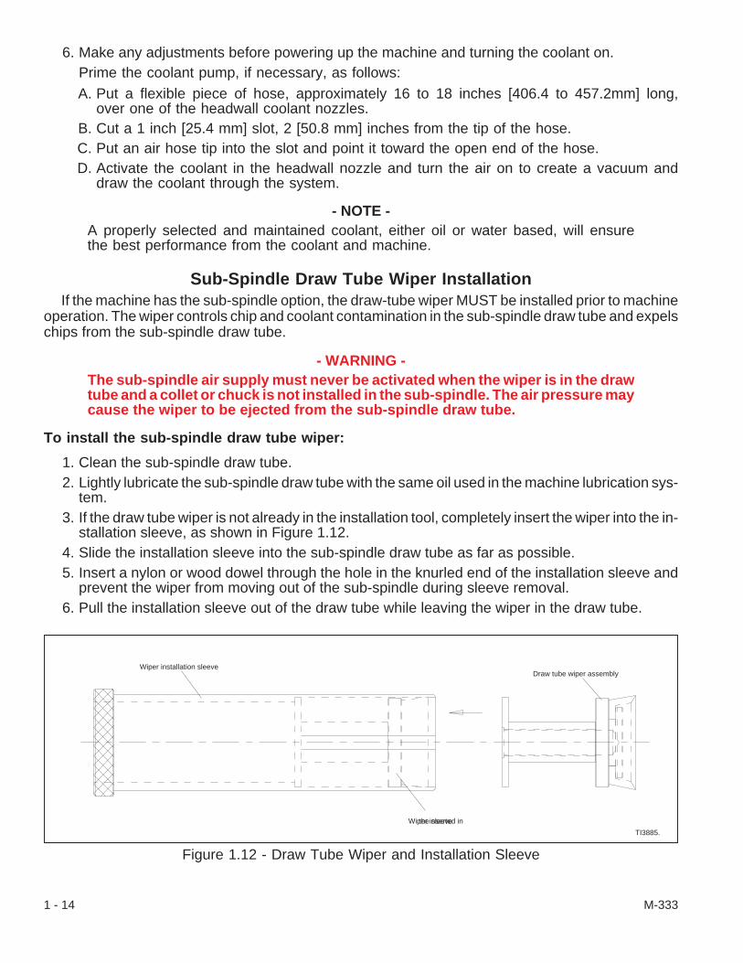
Sub-Spindle Draw Tube Wiper InstallationIf the machine has the sub-spindle option, the draw-tube wiper MUST be installed prior to machine
operation. The wiper controls chip and coolant contamination in the sub-spindle draw tube and expelschips from the sub-spindle draw tube.
- WARNING -The sub-spindle air supply must never be activated when the wiper is in the drawtube and a collet or chuck is not installed in the sub-spindle. The air pressure maycause the wiper to be ejected from the sub-spindle draw tube.
To install the sub-spindle draw tube wiper:
1. Clean the sub-spindle draw tube.2. Lightly lubricate the sub-spindle draw tube with the same oil used in the machine lubrication sys-
tem.3. If the draw tube wiper is not already in the installation tool, completely insert the wiper into the in-
stallation sleeve, as shown in Figure 1.12.4. Slide the installation sleeve into the sub-spindle draw tube as far as possible.5. Insert a nylon or wood dowel through the hole in the knurled end of the installation sleeve and
prevent the wiper from moving out of the sub-spindle during sleeve removal.6. Pull the installation sleeve out of the draw tube while leaving the wiper in the draw tube.
1 - 14 M-333
Figure 1.12 - Draw Tube Wiper and Installation Sleeve
Wiper installation sleeve
Wiper inserted inthe sleeve
Draw tube wiper assembly
TI3885.

Non-Metallic Materials Typically Found in Hardinge Machine Construction:
nitrile
neoprene
fluorocarbon rubber
urethane
silicone rubbers
cork-nitrile composites
polyurethane enamel
acetal plastics
polycarbonates
nylons
phenolic plastics
polyethylene
PVC
PTFE (polytetrafluoroethylene)
- NOTES -
M-333 1 - 15

- NOTES -
1 - 16 M-333

CHAPTER 2 - POWER-UP PROCEDURE
- CAUTION -The recommended operating temperature range is 50 to 114° F [7 to 46° C].
IntroductionThe power-up procedure for the CONQUEST® T51 and CONQUEST T65 series CNC lathe is a
systematic method of safely turning on the control and readying the machine for operation. Thepower-up procedure and maintenance on the control are normally performed with the power casedoor closed. However, if the door is opened during an operation, the door interlock switch turns thepower off.
- WARNING -During some maintenance procedures it may be necessary to have the powercase door and/or the control case door open. The control interlock switch isa safety device incorporated for your protection and is to be overridden onlywhen work is being done by a trained electrical technician. While the powercase and/or control case door is open, the person doing maintenance will beclose to high voltage electricity.
BE EXTREMELY CAUTIOUS
Basic Machine Power-Up
To power-up the machine:
1. If it is necessary to unlock the machine, obtain permission from the proper authority and havemain disconnect switch “A”, Figure 2.1, unlocked at center lock-out tab “B”. Also make certainthat main air lock-out valve “C”, Figure 2.2, is unlocked.
2. Turn main disconnect switch “A”, ON.
- WARNING -DO NOT look or feel under the mainair lock-out valve when purging thevalve or draining the filter bowl.High pressure air and contaminatescould be discharged from the open-ing.
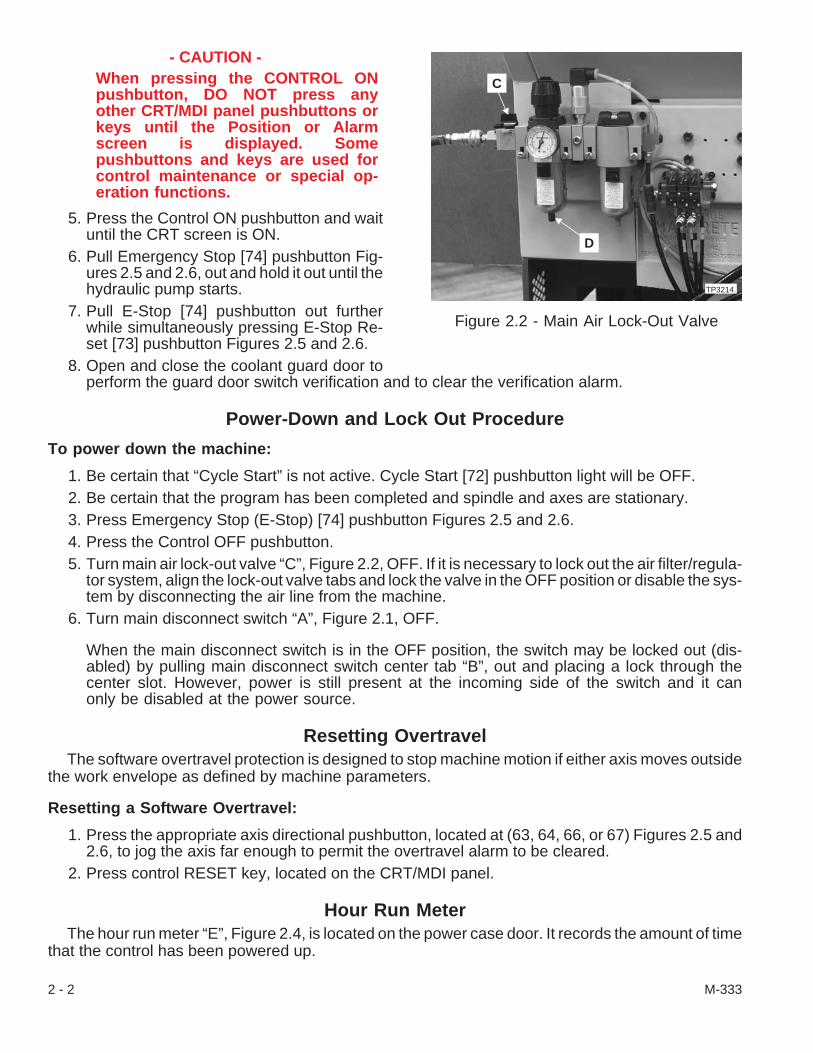
3. Turn main air lock-out valve “C”, ON. Purgethe air lock-out valve by turning the knob toany of the positions other than the ON orOFF positions and then move the knob tothe ON position. Drain the filter bowl(s)
4. Check the lubricant and coolant levels. Ifnecessary, add lubricant and coolant. Re-fer to Chapter 4 - Coolant Facilities andChapter 6 - Lubrication.
M-333 2 - 1
Figure 2.1 - Main Disconnect Switch withLock-Out Tab
TP3159.
A
B
- CAUTION -When pressing the CONTROL ONpushbutton, DO NOT press anyother CRT/MDI panel pushbuttons orkeys until the Position or Alarmscreen is displayed. Somepushbuttons and keys are used forcontrol maintenance or special op-eration functions.
5. Press the Control ON pushbutton and waituntil the CRT screen is ON.
6. Pull Emergency Stop [74] pushbutton Fig-ures 2.5 and 2.6, out and hold it out until thehydraulic pump starts.
7. Pull E-Stop [74] pushbutton out furtherwhile simultaneously pressing E-Stop Re-set [73] pushbutton Figures 2.5 and 2.6.
8. Open and close the coolant guard door toperform the guard door switch verification and to clear the verification alarm.
Power-Down and Lock Out Procedure
To power down the machine:
1. Be certain that “Cycle Start” is not active. Cycle Start [72] pushbutton light will be OFF.2. Be certain that the program has been completed and spindle and axes are stationary.3. Press Emergency Stop (E-Stop) [74] pushbutton Figures 2.5 and 2.6.4. Press the Control OFF pushbutton.5. Turn main air lock-out valve “C”, Figure 2.2, OFF. If it is necessary to lock out the air filter/regula-
tor system, align the lock-out valve tabs and lock the valve in the OFF position or disable the sys-tem by disconnecting the air line from the machine.
6. Turn main disconnect switch “A”, Figure 2.1, OFF.
When the main disconnect switch is in the OFF position, the switch may be locked out (dis-abled) by pulling main disconnect switch center tab “B”, out and placing a lock through thecenter slot. However, power is still present at the incoming side of the switch and it canonly be disabled at the power source.
Resetting OvertravelThe software overtravel protection is designed to stop machine motion if either axis moves outside
the work envelope as defined by machine parameters.
Resetting a Software Overtravel:
1. Press the appropriate axis directional pushbutton, located at (63, 64, 66, or 67) Figures 2.5 and2.6, to jog the axis far enough to permit the overtravel alarm to be cleared.
2. Press control RESET key, located on the CRT/MDI panel.
Hour Run MeterThe hour run meter “E”, Figure 2.4, is located on the power case door. It records the amount of time
that the control has been powered up.
2 - 2 M-333
Figure 2.2 - Main Air Lock-Out Valve
TP3214.
C
D

Turret Zero ReturnThe turret top plate(s) must be zero returned (syn-
chronized with the machine control) if the turret topplate(s) or end-working turret is interrupted while in-dexing. Top plate indexing can be interrupted by anelectrical outage, or by pressing either the RESET key or the Emergency Stop pushbutton while thetop plate(s) is in motion. When zero returning the turret(s), the top plate will continue to the original sta-tion during interruption or to the selected station.
To turret zero return (synchronize the turret/end-working top plate):
1. Pull Emergency Stop [74] pushbutton Figures 2.5 and 2.6, out to release it.2. Press and hold Zero Return [69] pushbutton.3. Be certain that turret station switch [47] is set to a valid turret station.4. Press the Turret 1 Index [44] pushbutton. The main (upper) turret will home (zero return) the top
plate.5. If it is necessary to zero return the lower axis turret, press the Turret 2 Index [46] pushbutton. The
lower axis top plate will index to the home position.6. Reset the program to the beginning of the current tool operation.
M-333 2 - 3
Figure 2.3 - CRT/MDI (Data Input Panel)
TPA2803
Figure 2.4 - Hour Run Meter
TP3212
E
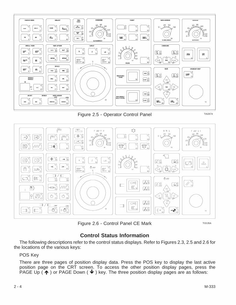
Control Status InformationThe following descriptions refer to the control status displays. Refer to Figures 2.3, 2.5 and 2.6 for
the locations of the various keys:
POS Key
There are three pages of position display data. Press the POS key to display the last activeposition page on the CRT screen. To access the other position display pages, press thePAGE Up ( � ) or PAGE Down ( � ) key. The three position display pages are as follows:
2 - 4 M-333
Figure 2.5 - Operator Control Panel TIA2674
Figure 2.6 - Control Panel CE Mark TI3135A
1. ALL (Overall Position Display): This page shows the active program number and block numberare displayed in the upper right-hand corner of the CRT screen if the control is in AUTO.
(a) Relative: The Axis position is displayed on the Relative Coordinate System as U and Wcoordinates.
(b) Absolute: The Axis position is displayed on the Work Coordinate System. Afterpower-up, the origin of the Work Coordinate System is the intersection of the spindleface and the spindle centerline. Position is displayed as X and Z coordinates. This origincan be relocated by any one of the following:
Active set of tool offsetsPosition Reset operationWorkshift offset
(c) Machine: Displays the Axis position in relation to the Reference Zero position. On ma-chines set up for inch programming, the X Axis Reference Zero position is 6.625 inchesbehind the spindle centerline (away from the operator) and the Z Axis Reference Zeroposition is 23.00 inches from the face of the spindle. On machines set up for metric pro-gramming, the X Axis Zero Return position is 168 mm behind the spindle centerline(away from the operator) and the Z Axis Zero Return position is 584 mm from the faceof the spindle.
(d) Distance to Go: Distance remaining between current axis position and the programmedaxis position. This register is displayed only while the control is in AUTO or MDI mode.
2. Actual Position Display. Refer to part “b” under “Overall Position Display”, above.3. Relative Position Display. Refer to part “a” under “Overall Position Display”, above.PRGRM Key
Eleven blocks of the active program, the active part program number, and the active block se-quence number will be displayed in the upper right-hand corner of the CRT screen when thePRGRM key is pressed. To display other pages of the program, select EDIT mode and usethe PAGE Up ( � ) or PAGE Down ( � ) keys to read through the program.
During execution of the active part program, the cursor will be positioned under the sequencenumber of the active block. To return to the start of the program, press the following keys inthe sequence shown:
1. RESET2. PRGRM3. CURSOR UP ( � )
MENU/OFSET key
The following soft keys are displayed when the MENU/OFSET key is pressed: WEAR,GEOM, W.SHFT, and MACRO.
WEAR: Consists of four pages of Wear offsets, eight offsets on each page.
GEOM: Consists of four pages of Geometry offsets, eight offsets on each page.
W.SHFT: Consists of one page of Workshift offsets, two workshifts on the page.
Refer to Operator’s Manual (M-332) Chapter 2 for information about additional keys andcontrol status.
M-333 2 - 5
Power On with Power Case and/or Control Case Door Open
- WARNING -During some maintenance procedures it may be necessary to have the con-trol case door and/or power case door open. The control interlock switch is asafety device incorporated for your protection and is to be overridden onlywhen work is being done by a trained electrical technician. While the controlcase or power case door(s) is open, the person doing maintenance will beclose to high voltage electricity.
BE EXTREMELY CAUTIOUS.
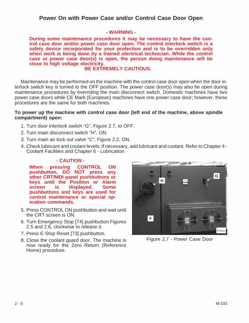
Maintenance may be performed on the machine with the control case door open when the door in-terlock switch key is turned to the OFF position. The power case door(s) may also be open duringmaintenance procedures by overriding the main disconnect switch. Domestic machines have twopower case doors while CE Mark (European) machines have one power case door; however, theseprocedures are the same for both machines.
To power up the machine with control case door (left end of the machine, above spindlecompartment) open:
1. Turn door interlock switch “G”, Figure 2.7, to OFF.2. Turn main disconnect switch “H”, ON.3. Turn main air lock out valve “C”, Figure 2.2, ON.4. Check lubricant and coolant levels. If necessary, add lubricant and coolant. Refer to Chapter 4 -
Coolant Facilities and Chapter 6 - Lubrication.
- CAUTION -When pressing CONTROL ONpushbutton, DO NOT press anyother CRT/MDI panel pushbuttons orkeys until the Position or Alarmscreen is displayed. Somepushbuttons and keys are used forcontrol maintenance or special op-eration commands.
5. Press CONTROL ON pushbutton and wait untilthe CRT screen is ON.
6. Turn Emergency Stop [74] pushbutton Figures2.5 and 2.6, clockwise to release it.
7. Press E-Stop Reset [73] pushbutton.8. Close the coolant guard door. The machine is
now ready for the Zero Return (ReferenceHome) procedure.
2 - 6 M-333
Figure 2.7 - Power Case Door
TP3212
F
HG

To open control case door when the machine is ON:
1. Leave main disconnect switch “H”, Figure 2.7, ON.2. Turn the door interlock switch “G”, to OFF.3. Use the key to turn both latches and open the control case door.
To open power case door(s) “F”, Figure 2.7, when the machine is ON (powered up):
1. Leave main disconnect switch “M”, ON.2. Use the key to unfasten the latches on the power case door(s).3. Place a flat blade screwdriver in the slot above or to the right of the lever on the main disconnect
switch and press downward until the door unlatches. Pull the power case door open.4. Perform whatever maintenance is required.5. Place a flat blade screwdriver in the slot and press the door closed while pressing downward
with the screwdriver until the door latches.6. Use the key and secure the latches on the power case door.
To power up the machine when power case door “F”, Figure 2.7, is open:
1. Close the power case door but do not fasten the latches.2. Turn main disconnect switch “H”, ON and power up the machine.3. Put a small screwdriver in the groove in the slot above or to the right of the lever on the main dis-
connect switch and rotate (slide) it down to override the main disconnect switch.4. Pull the power case door open.
- NOTES -
M-333 2 - 7

- NOTES -
2 - 8 M-333
CHAPTER 3 - AIR FACILITIES
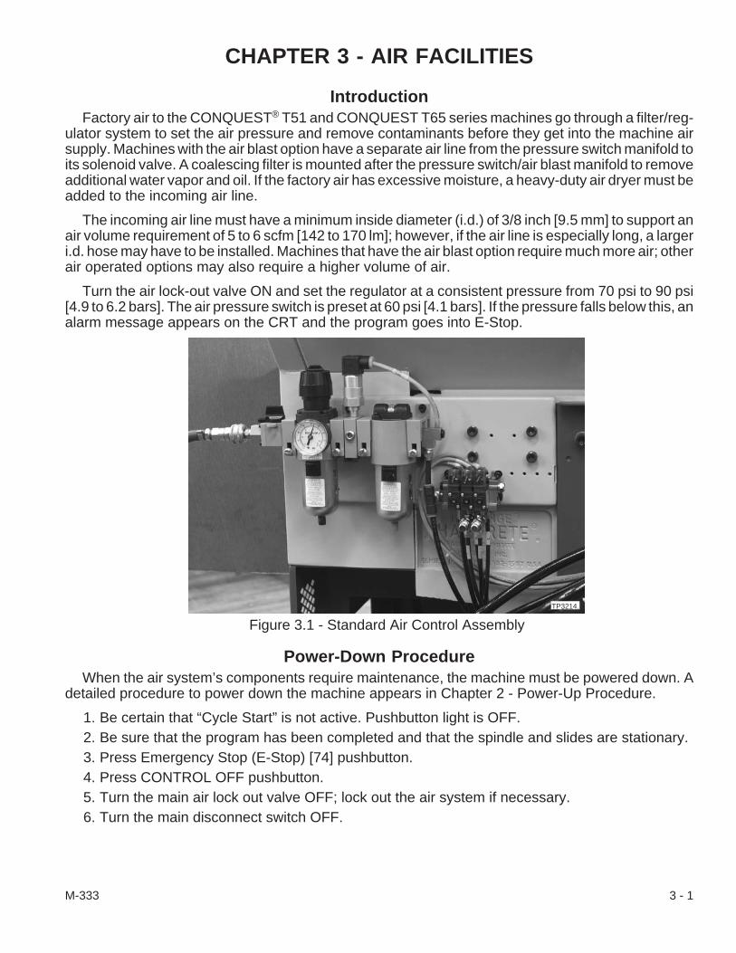
IntroductionFactory air to the CONQUEST® T51 and CONQUEST T65 series machines go through a filter/reg-
ulator system to set the air pressure and remove contaminants before they get into the machine airsupply. Machines with the air blast option have a separate air line from the pressure switch manifold toits solenoid valve. A coalescing filter is mounted after the pressure switch/air blast manifold to removeadditional water vapor and oil. If the factory air has excessive moisture, a heavy-duty air dryer must beadded to the incoming air line.
The incoming air line must have a minimum inside diameter (i.d.) of 3/8 inch [9.5 mm] to support anair volume requirement of 5 to 6 scfm [142 to 170 lm]; however, if the air line is especially long, a largeri.d. hose may have to be installed. Machines that have the air blast option require much more air; otherair operated options may also require a higher volume of air.
Turn the air lock-out valve ON and set the regulator at a consistent pressure from 70 psi to 90 psi[4.9 to 6.2 bars]. The air pressure switch is preset at 60 psi [4.1 bars]. If the pressure falls below this, analarm message appears on the CRT and the program goes into E-Stop.
Power-Down ProcedureWhen the air system’s components require maintenance, the machine must be powered down. A
detailed procedure to power down the machine appears in Chapter 2 - Power-Up Procedure.
1. Be certain that “Cycle Start” is not active. Pushbutton light is OFF.2. Be sure that the program has been completed and that the spindle and slides are stationary.3. Press Emergency Stop (E-Stop) [74] pushbutton.4. Press CONTROL OFF pushbutton.5. Turn the main air lock out valve OFF; lock out the air system if necessary.6. Turn the main disconnect switch OFF.
M-333 3 - 1
Figure 3.1 - Standard Air Control Assembly
TP3214.
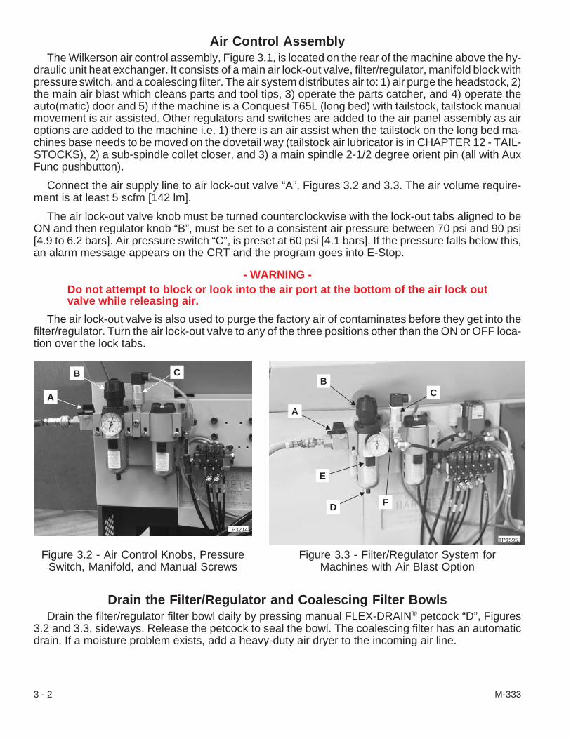
Air Control AssemblyThe Wilkerson air control assembly, Figure 3.1, is located on the rear of the machine above the hy-
draulic unit heat exchanger. It consists of a main air lock-out valve, filter/regulator, manifold block withpressure switch, and a coalescing filter. The air system distributes air to: 1) air purge the headstock, 2)the main air blast which cleans parts and tool tips, 3) operate the parts catcher, and 4) operate theauto(matic) door and 5) if the machine is a Conquest T65L (long bed) with tailstock, tailstock manualmovement is air assisted. Other regulators and switches are added to the air panel assembly as airoptions are added to the machine i.e. 1) there is an air assist when the tailstock on the long bed ma-chines base needs to be moved on the dovetail way (tailstock air lubricator is in CHAPTER 12 - TAIL-STOCKS), 2) a sub-spindle collet closer, and 3) a main spindle 2-1/2 degree orient pin (all with AuxFunc pushbutton).
Connect the air supply line to air lock-out valve “A”, Figures 3.2 and 3.3. The air volume require-ment is at least 5 scfm [142 lm].
The air lock-out valve knob must be turned counterclockwise with the lock-out tabs aligned to beON and then regulator knob “B”, must be set to a consistent air pressure between 70 psi and 90 psi[4.9 to 6.2 bars]. Air pressure switch “C”, is preset at 60 psi [4.1 bars]. If the pressure falls below this,an alarm message appears on the CRT and the program goes into E-Stop.
- WARNING -Do not attempt to block or look into the air port at the bottom of the air lock outvalve while releasing air.
The air lock-out valve is also used to purge the factory air of contaminates before they get into thefilter/regulator. Turn the air lock-out valve to any of the three positions other than the ON or OFF loca-tion over the lock tabs.
Drain the Filter/Regulator and Coalescing Filter BowlsDrain the filter/regulator filter bowl daily by pressing manual FLEX-DRAIN® petcock “D”, Figures
3.2 and 3.3, sideways. Release the petcock to seal the bowl. The coalescing filter has an automaticdrain. If a moisture problem exists, add a heavy-duty air dryer to the incoming air line.
3 - 2 M-333
Figure 3.2 - Air Control Knobs, PressureSwitch, Manifold, and Manual Screws
A
B C
TP3214.
Figure 3.3 - Filter/Regulator System forMachines with Air Blast Option
A
BC
TP1595.
D
E
F

Replace the FiltersDrain the filter/regulator bowl daily and check the air system bowls once a week for contaminates. If
the sight gauge on the coalescing filter head is red, change the filter.
1. Power down the machine. Make certain that the air lock-out valve is OFF. Align the lock-outvalve tabs and lock the valve in the OFF position.
2. Clean the main air lock out valve (air inlet) filter as follows:A. Drain any water from the bottom of the filter/regulator by pressing the FLEX-DRAIN®
petcock sideways to drain the bowl. Release the petcock.B. Pull down on the black latch “E”, on the side of the outer shell of the bowls. Twist the
shell counterclockwise to release it.C. Wipe the bowl clean with a lint-free cloth and check the O-ring for damage. Replace the
O-ring and/or bowl if necessary.
- NOTE -If the sight gauge on the coalescing filter head is red, change the filter.
D. Clean or replace the filters as necessary. To release the filter, unscrew the nylon fixture.Thread the new filter on the nipple until it is snug.
E. Mount the bowl on the head as follows:1) Put the plastic bowl into the shell.2) Align the bowl in the head and press the shell up into place. Rotate the shell clock-
wise until the latch “clicks” to seat the O-ring.3) Pull down on the shell to confirm that the bowl is in place.
3. Remove the lock from the lock-out tab and power up the machine. Turn the air lock out valve ON;set the regulator to 85 psi [5.9 bars] and check for air leaks. Correct any air leaks as necessary.
4. Set the regulator below 60 psi [4.2 bars] to test the pressure switch. The control will go into anEmergency Stop (E-Stop) condition.
5. Set the regulator to an operating pressure between 70 psi to 90 psi [4.9 to 6.2 bars]. Check theair system bowl for contamination, moisture, or air leaks and correct any problems as neces-sary.
6. Press the E-Stop Reset [73] pushbutton if it is still necessary to clear “1017 Main Air PressureLow” alarm message from the CRT.
Replace the Air Control Assembly ComponentsAny of the air control assembly components can be replaced if they become damaged. The air con-
trol assembly can also be replaced as a unit.
1. Power down the machine. Make certain that the air lock-out valve is OFF. Align the lock-outvalve tabs and lock the valve in the OFF position.
2. Disconnect the main air line from the air lock out valve.3. Unthread the screw and pull the electric plug straight up from the top of pressure switch “C”, Fig-
ure 3.2.4. Disconnect the air line(s) from the air manifold.5. Unthread the screws and remove the air assembly unit from the panel.
(continued on the next page)
M-333 3 - 3

- NOTE -The air control assembly components are fastened together with tabs ortaper-railed blocks. The standard machine air assembly components have tabs.
6. Loosen, but do not remove, the screws in the tab or taper-railed block on either side of the com-ponent being replaced. Carefully slide the component out of the blocks.
7. Make certain that the O-rings are in place and mount the new component between the tab ortaper-railed blocks. Tighten the screw in each block.
8. Mount the air assembly unit on the panel. Tighten the screws that fasten it in place.
- NOTE -Use just enough sealant to secure the fitting when fastening the air lines to themanifold(s). Do not apply sealant to the first few threads.
9. Fasten the air line(s) to the manifold.10. Connect the electric plug to the top of the of pressure switch. Thread the screw into the pressure
switch to secure the plug.11. Connect the main air line and turn the air source on.12. Remove the lock from the lock-out tab and power up the machine. Set the regulator to an operat-
ing pressure between 70 psi and 90 psi [4.9 to 6.2 bars].13. Press the E-Stop Reset [73] pushbutton if it is still necessary to clear “1017 Main Air Pressure
Low” alarm message from the CRT.14. Check the air system bowl for contamination, moisture, or air leaks and correct any problems as
necessary.
Replace the Pressure SwitchPressure switch “C”, Figures 3.2 and 3.3, is designed to send a signal to the control and an alarm
message appears on the CRT when the air pressure falls below 60 psi [4.2 bars].
1. Power down the machine. Make certain that the air lock out valve is OFF. Align the lock-out valvetabs and lock the valve in the OFF position.
2. Unthread the screw that holds the electrical plug to the top of the switch. Pull the plug straight upto remove it from the switch.
3. Unthread the pressure switch from the manifold. The switch is tightened to the manifold with lighttorque pressure, however, a wrench may be necessary to unthread it.
- NOTE -Use just enough sealant to secure the fitting when fastening the pressure switch tothe manifold. Do not apply sealant to the first few threads.
4. Thread a new pressure switch on the manifold and only tighten it to 50 in/pounds[5.6 N•m].
5. Connect the electric plug to the pressure switch. Secure the plug with the screw.6. Remove the lock from the lock-out tab and power up the machine. Set the regulator to an operat-
ing pressure between 70 psi to 90 psi [4.9 to 6.2 bars].7. Press the E-Stop Reset [73] pushbutton if it is still necessary to clear “1017 Main Air Pressure
Low” alarm message from the CRT.8. Check the air system bowl for contamination, moisture, or air leaks and correct any problems as
necessary.
3 - 4 M-333

Replace or Clean the ManifoldAir manifold “F”, Figure 3.3, has no moving parts, but if it is not dispersing air as it should or if it be-
comes damaged, it may need to be replaced or cleaned. There are additional ports in the manifold foruse when other air options are added to the machine.
1. Power down the machine. Make certain that the air lock out valve is OFF. Align the lock-out valvetabs and lock the valve in the OFF position.
2. Disconnect the air lines from the manifold.3. Unthread the manifold and fitting from the air assembly coalescing filter head. The air fitting may
have to be removed from the manifold if the manifold is to be replaced.
- NOTE -Use just enough sealant to secure the fitting when fastening the air system compo-nents together. Do not apply sealant to the first few threads.
4. Thread the plugs and air line fittings into the new manifold and mount it on the air assembly unit.Attach the air lines to the fittings on the manifold.
5. Connect the electric plug to the top of the of pressure switch. Secure the plug in place with thescrew.
6. Remove the lock from the lock-out tab and power up the machine. Set the regulator to an operat-ing pressure between 70 psi and 90 psi [4.9 to 6.2 bars].
7. Press the E-Stop Reset [73] pushbutton if it is still necessary to clear “1017 Main Air PressureLow” alarm message from the CRT.
8. Check the air system bowl for contamination, moisture, or air leaks and correct any problems asnecessary.
Solenoid ValvesSolenoid valves “G”, Figure 3.4, are horizontally stacked when mounted on the air panel. Most air
system options are activated through solenoid valves and are available on the machine when origi-nally ordered or some of the options can be retrofitted when necessary.
Reference information is included in each air option retrofit kit and with each machine. Electricalconnections, air line connections, cable markings, routings (ducting) through the machine, and loca-tion of the option parts are on the option information sheets and on the tags on the machine.
To replace or add a solenoid valve:
1. Power down the machine. Make certain that theair lock out valve is OFF. Align the lock-outvalve tabs and lock the valve in the OFF posi-tion.
2. Refer to the schematic chart on the panel toidentify which valve needs to be replaced. If avalve is to be added, make certain that an iden-tification stamp is placed on the chart.
(continued on the next page)
M-333 3 - 5
Figure 3.4 - Solenoid Valves
G
TP1595.
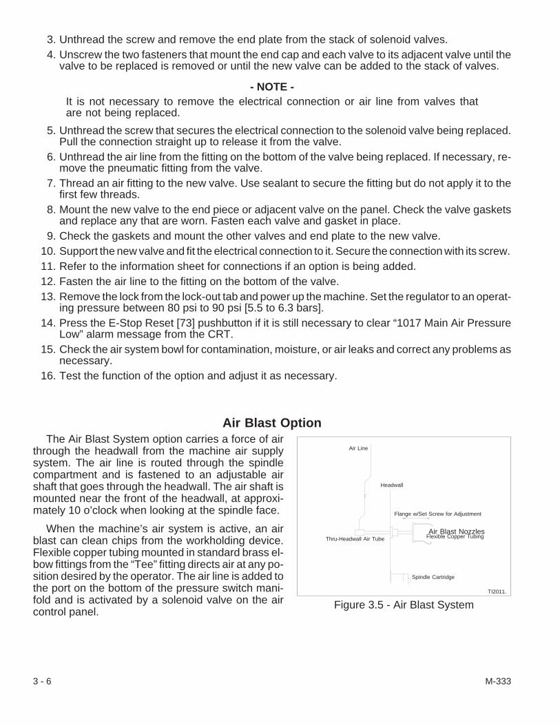
3. Unthread the screw and remove the end plate from the stack of solenoid valves.4. Unscrew the two fasteners that mount the end cap and each valve to its adjacent valve until the
valve to be replaced is removed or until the new valve can be added to the stack of valves.
- NOTE -It is not necessary to remove the electrical connection or air line from valves thatare not being replaced.
5. Unthread the screw that secures the electrical connection to the solenoid valve being replaced.Pull the connection straight up to release it from the valve.
6. Unthread the air line from the fitting on the bottom of the valve being replaced. If necessary, re-move the pneumatic fitting from the valve.
7. Thread an air fitting to the new valve. Use sealant to secure the fitting but do not apply it to thefirst few threads.
8. Mount the new valve to the end piece or adjacent valve on the panel. Check the valve gasketsand replace any that are worn. Fasten each valve and gasket in place.
9. Check the gaskets and mount the other valves and end plate to the new valve.10. Support the new valve and fit the electrical connection to it. Secure the connection with its screw.11. Refer to the information sheet for connections if an option is being added.12. Fasten the air line to the fitting on the bottom of the valve.13. Remove the lock from the lock-out tab and power up the machine. Set the regulator to an operat-
ing pressure between 80 psi to 90 psi [5.5 to 6.3 bars].14. Press the E-Stop Reset [73] pushbutton if it is still necessary to clear “1017 Main Air Pressure
Low” alarm message from the CRT.15. Check the air system bowl for contamination, moisture, or air leaks and correct any problems as
necessary.16. Test the function of the option and adjust it as necessary.
Air Blast OptionThe Air Blast System option carries a force of air
through the headwall from the machine air supplysystem. The air line is routed through the spindlecompartment and is fastened to an adjustable airshaft that goes through the headwall. The air shaft ismounted near the front of the headwall, at approxi-mately 10 o’clock when looking at the spindle face.
When the machine’s air system is active, an airblast can clean chips from the workholding device.Flexible copper tubing mounted in standard brass el-bow fittings from the “Tee” fitting directs air at any po-sition desired by the operator. The air line is added tothe port on the bottom of the pressure switch mani-fold and is activated by a solenoid valve on the aircontrol panel.
3 - 6 M-333
Figure 3.5 - Air Blast System
Air Line
Headwall
Flange w/Set Screw for Adjustment
Air Blast NozzlesFlexible Copper Tubing
Spindle Cartridge
Thru-Headwall Air Tube
TI2011.

The air blast is program activated by an M36 code and de-activated by an M37 code. The air blastcan also be activated by the Air Blast [17] pushbutton under the “Coolant” heading on the main controlpanel. If the air blast has been activated by an M36, pressing the AIR Blast pushbutton will turn the airblast off and vice versa.
- NOTES -
M-333 3 - 7

- NOTES -
3 - 8 M-333
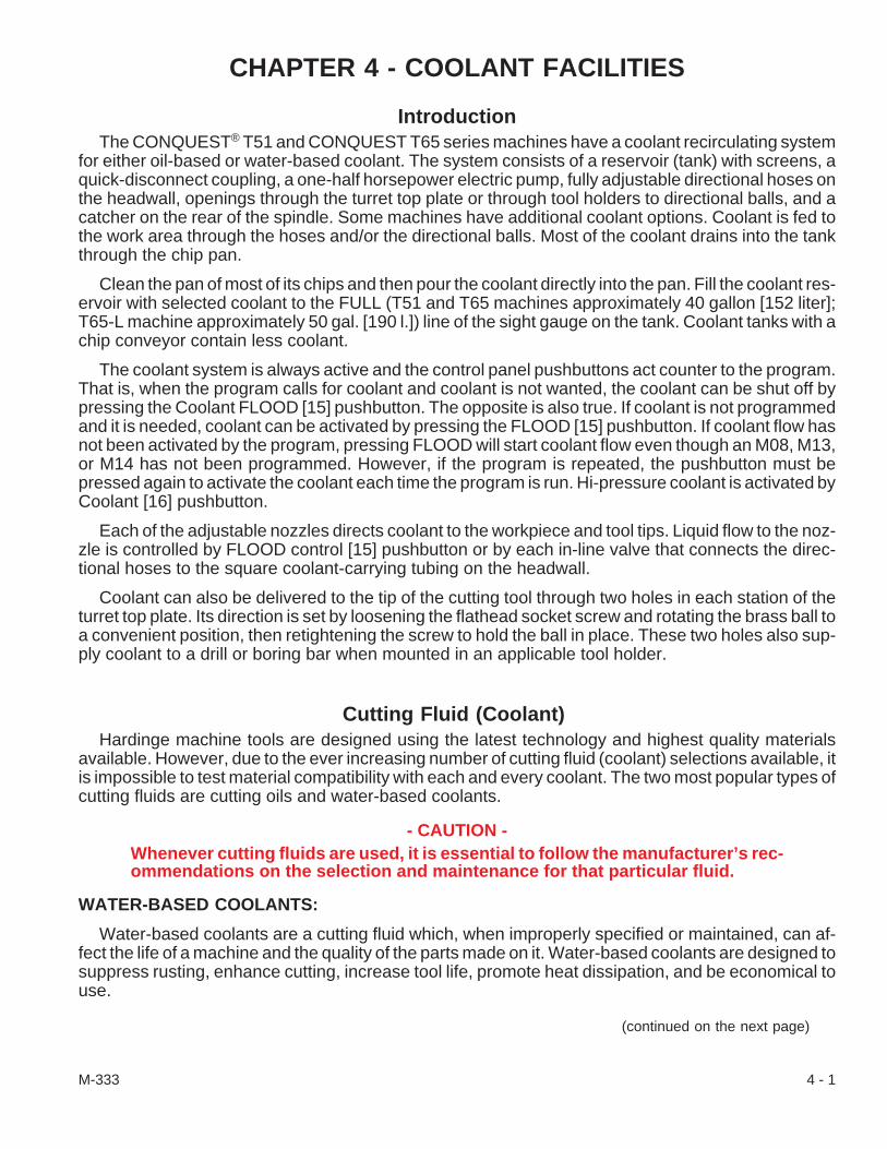
CHAPTER 4 - COOLANT FACILITIES
IntroductionThe CONQUEST® T51 and CONQUEST T65 series machines have a coolant recirculating system
for either oil-based or water-based coolant. The system consists of a reservoir (tank) with screens, aquick-disconnect coupling, a one-half horsepower electric pump, fully adjustable directional hoses onthe headwall, openings through the turret top plate or through tool holders to directional balls, and acatcher on the rear of the spindle. Some machines have additional coolant options. Coolant is fed tothe work area through the hoses and/or the directional balls. Most of the coolant drains into the tankthrough the chip pan.
Clean the pan of most of its chips and then pour the coolant directly into the pan. Fill the coolant res-ervoir with selected coolant to the FULL (T51 and T65 machines approximately 40 gallon [152 liter];T65-L machine approximately 50 gal. [190 l.]) line of the sight gauge on the tank. Coolant tanks with achip conveyor contain less coolant.
The coolant system is always active and the control panel pushbuttons act counter to the program.That is, when the program calls for coolant and coolant is not wanted, the coolant can be shut off bypressing the Coolant FLOOD [15] pushbutton. The opposite is also true. If coolant is not programmedand it is needed, coolant can be activated by pressing the FLOOD [15] pushbutton. If coolant flow hasnot been activated by the program, pressing FLOOD will start coolant flow even though an M08, M13,or M14 has not been programmed. However, if the program is repeated, the pushbutton must bepressed again to activate the coolant each time the program is run. Hi-pressure coolant is activated byCoolant [16] pushbutton.
Each of the adjustable nozzles directs coolant to the workpiece and tool tips. Liquid flow to the noz-zle is controlled by FLOOD control [15] pushbutton or by each in-line valve that connects the direc-tional hoses to the square coolant-carrying tubing on the headwall.
Coolant can also be delivered to the tip of the cutting tool through two holes in each station of theturret top plate. Its direction is set by loosening the flathead socket screw and rotating the brass ball toa convenient position, then retightening the screw to hold the ball in place. These two holes also sup-ply coolant to a drill or boring bar when mounted in an applicable tool holder.
Cutting Fluid (Coolant)Hardinge machine tools are designed using the latest technology and highest quality materials
available. However, due to the ever increasing number of cutting fluid (coolant) selections available, itis impossible to test material compatibility with each and every coolant. The two most popular types ofcutting fluids are cutting oils and water-based coolants.
- CAUTION -Whenever cutting fluids are used, it is essential to follow the manufacturer’s rec-ommendations on the selection and maintenance for that particular fluid.
WATER-BASED COOLANTS:
Water-based coolants are a cutting fluid which, when improperly specified or maintained, can af-fect the life of a machine and the quality of the parts made on it. Water-based coolants are designed tosuppress rusting, enhance cutting, increase tool life, promote heat dissipation, and be economical touse.
(continued on the next page)
M-333 4 - 1

Some water-based coolants may cause machine corrosion problems and be incompatible with ma-chine components, especially if the fluid is not maintained correctly. Poorly maintained coolants mayresult in rancidity, poor tool life, staining, rusting, foaming, etc., which affect machine performanceand may cause health problems such as dermatitis. Water-based coolants must be correctly specifiedaccording to the machined materials and ensure compatibility with the machine’s components. Referto the list of common materials used in the manufacture of Hardinge machines which follows this sec-tion.
It is extremely critical to follow the coolant manufacturer’s recommendations when using a wa-ter-based coolant. Maintaining coolants per the manufacture’s recommendations will increasethe machine’s useful life and will minimize corrosion, rusting, staining, etc., and health prob-lems such as dermatitis. At a minimum, the coolant maintenance should include daily checks andcorrection of coolant concentration, a measure of coolant pH, and removal of any tramp oil from themachine sump.
To prepare the coolant system:
1. Roll the coolant reservoir (tank) into the opening under the front of the machine. Do not force thetank in place and take care of the skirting (neoprene splash shields) inside the work area.
2. Connect the coolant hose to the fitting on the tank by pulling back on the knurled ring on thequick-disconnect coupling, slipping the coupling over the fitting and releasing the ring to securethe coolant hose. Check the connection to make certain that it is secure.
3. Put the way lube tramp oil pan in place.4. Adjust the skirting and check inside the work area to see that coolant will drain back into the chip
pan.5. Pour the coolant directly into the chip pan of the coolant reservoir. Fill the tank with the approved
coolant to the FULL line of the sight gauge.The long bed design reservoir holds approximately 50 gallons [190 liter] and 40 gal. [152 l.]for reservoirs that have a chip conveyor; the standard machine reservoir holds 40 gallons[152 liter] and 32 gal. [122 l.] for chip conveyor reservoirs.
6. Make any adjustments before powering up the machine and turning the coolant on.Prime the coolant pump, if necessary, as follows:A. Put a flexible piece of hose, approximately 16 to 18 inches [406.4 to 457.2mm] long,
over one of the headwall coolant nozzles.B. Cut a 1 inch [25.4 mm] slot, 2 [50.8 mm] inches from the tip of the hose.C. Put an air hose tip into the slot and point it toward the open end of the hose.D. Activate the coolant in the headwall nozzle and turn the air on to create a vacuum and
draw the coolant through the system.
- NOTE -A properly selected and maintained coolant, either oil or water based, will ensurethe best performance from the coolant and machine.
4 - 2 M-333
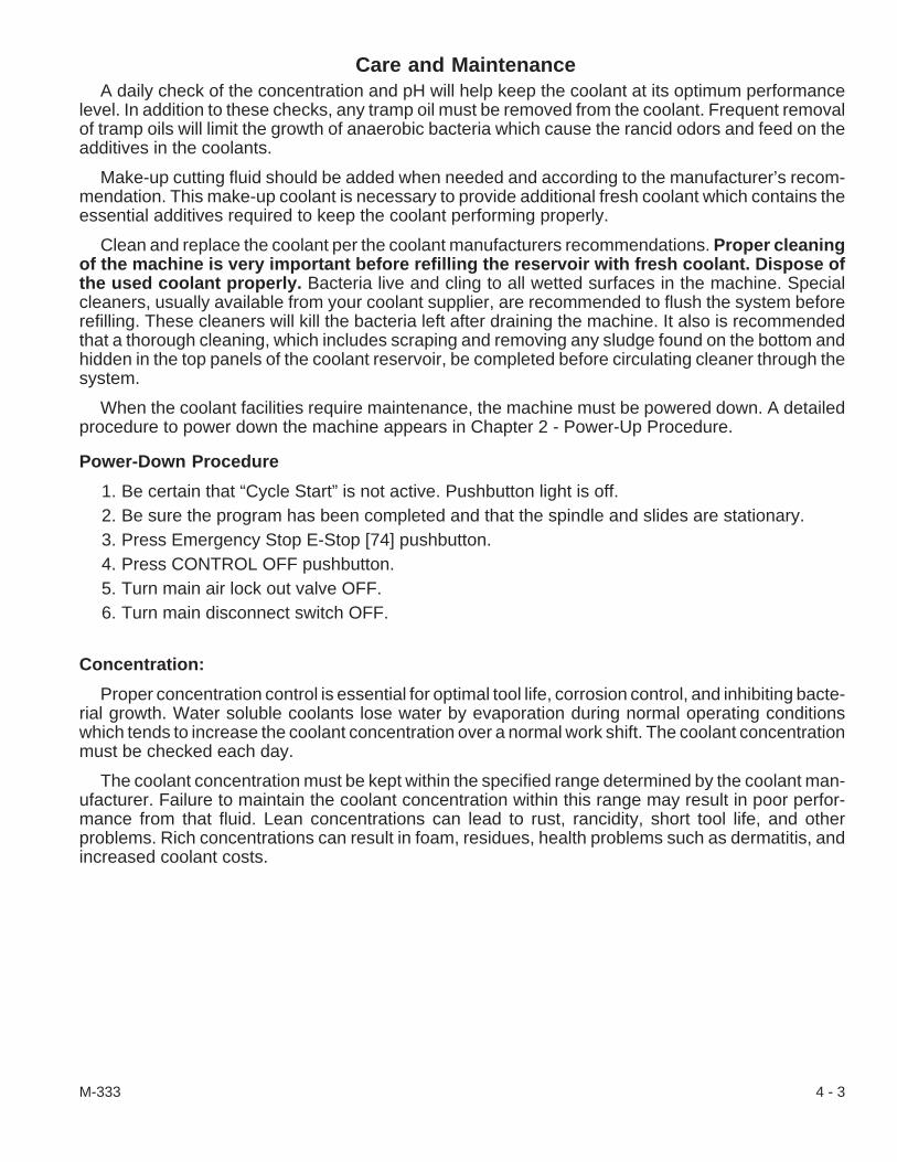
Care and MaintenanceA daily check of the concentration and pH will help keep the coolant at its optimum performance
level. In addition to these checks, any tramp oil must be removed from the coolant. Frequent removalof tramp oils will limit the growth of anaerobic bacteria which cause the rancid odors and feed on theadditives in the coolants.
Make-up cutting fluid should be added when needed and according to the manufacturer’s recom-mendation. This make-up coolant is necessary to provide additional fresh coolant which contains theessential additives required to keep the coolant performing properly.
Clean and replace the coolant per the coolant manufacturers recommendations. Proper cleaningof the machine is very important before refilling the reservoir with fresh coolant. Dispose ofthe used coolant properly. Bacteria live and cling to all wetted surfaces in the machine. Specialcleaners, usually available from your coolant supplier, are recommended to flush the system beforerefilling. These cleaners will kill the bacteria left after draining the machine. It also is recommendedthat a thorough cleaning, which includes scraping and removing any sludge found on the bottom andhidden in the top panels of the coolant reservoir, be completed before circulating cleaner through thesystem.
When the coolant facilities require maintenance, the machine must be powered down. A detailedprocedure to power down the machine appears in Chapter 2 - Power-Up Procedure.
Power-Down Procedure
1. Be certain that “Cycle Start” is not active. Pushbutton light is off.2. Be sure the program has been completed and that the spindle and slides are stationary.3. Press Emergency Stop E-Stop [74] pushbutton.4. Press CONTROL OFF pushbutton.5. Turn main air lock out valve OFF.6. Turn main disconnect switch OFF.
Concentration:
Proper concentration control is essential for optimal tool life, corrosion control, and inhibiting bacte-rial growth. Water soluble coolants lose water by evaporation during normal operating conditionswhich tends to increase the coolant concentration over a normal work shift. The coolant concentrationmust be checked each day.
The coolant concentration must be kept within the specified range determined by the coolant man-ufacturer. Failure to maintain the coolant concentration within this range may result in poor perfor-mance from that fluid. Lean concentrations can lead to rust, rancidity, short tool life, and otherproblems. Rich concentrations can result in foam, residues, health problems such as dermatitis, andincreased coolant costs.
M-333 4 - 3

pH:
pH is a measure of a solution’s alkalinity or acidity. There are two common methods used to deter-mine pH. One method is the use of special pH test paper and the other is a pH meter.
Water based coolants are designed to run within the pH range determined by the manufacturer.The pH of water based coolants typically runs on the alkaline side of the pH scale. A drop in pH indi-cates a growth of microbiological organisms (bacteria). These anaerobic bacteria live on the trampoils and additives found in the coolants. When these bacteria feed on the oils they release an acidicby-product which eventually drives the coolant towards a lower pH level. Typically, the pH range is be-tween 8.5 and 9.2.
Water Quality:
The water quality is also an important factor toward achieving optimum coolant performance. Wa-ter that contains dissolved minerals, bacteria, and other impurities (hard water) can some-times adversely affect the coolant selected. An indication of water related problems is theformation of a soap like scum which adheres to sumps, filters, etc. It is best to consult with your coolantrepresentative to determine your requirements.
Removing Chips and ShavingsThe chip pan/coolant reservoir is mounted on wheels and has a quick-disconnect coupling so that it
can be moved from the machine in several directions, refer to Figure 4.1. Information for the rear dis-charge coolant system is included with each step when possible and is in a section near the end of thischapter. The rear discharge chip conveyor pan/coolant reservoir can be disconnected and pulledstraight out from under the machine.
- WARNING -Use a rake and suitable container to remove metal chips and shavings from thechip pan. Injury may result from attempting to remove chips without a rake. Dis-pose of the chips and shavings in an environmentally safe manner.
- CAUTION -Be careful to clear the flexible skirting while moving the coolant reservoir fromthe machine and while re-installing it in place. A second person may be neces-sary to safely hold the skirting up out of the way.
4 - 4 M-333
Figure 4.1 - Convenient Areas for Tank Removal
TI2510.
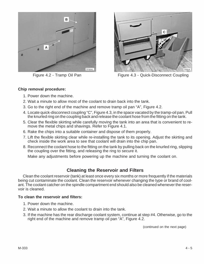
Chip removal procedure:
1. Power down the machine.2. Wait a minute to allow most of the coolant to drain back into the tank.3. Go to the right end of the machine and remove tramp oil pan “A”, Figure 4.2.4. Locate quick-disconnect coupling “C”, Figure 4.3, in the space vacated by the tramp-oil pan. Pull
the knurled ring on the coupling back and release the coolant hose from the fitting on the tank.5. Clear the flexible skirting while carefully moving the tank into an area that is convenient to re-
move the metal chips and shavings. Refer to Figure 4.1.6. Rake the chips into a suitable container and dispose of them properly.7. Lift the flexible skirting clear while re-installing the tank to its opening. Adjust the skirting and
check inside the work area to see that coolant will drain into the chip pan.8. Reconnect the coolant hose to the fitting on the tank by pulling back on the knurled ring, slipping
the coupling over the fitting, and releasing the ring to secure it.Make any adjustments before powering up the machine and turning the coolant on.
Cleaning the Reservoir and FiltersClean the coolant reservoir (tank) at least once every six months or more frequently if the materials
being cut contaminate the coolant. Clean the reservoir whenever changing the type or brand of cool-ant. The coolant catcher on the spindle compartment end should also be cleaned whenever the reser-voir is cleaned.
To clean the reservoir and filters:
1. Power down the machine.2. Wait a minute to allow the coolant to drain into the tank.3. If the machine has the rear discharge coolant system, continue at step #4. Otherwise, go to the
right end of the machine and remove tramp oil pan “A”, Figure 4.2.
(continued on the next page)
M-333 4 - 5
Figure 4.2 - Tramp Oil Pan
TP3041.
B
A
Figure 4.3 - Quick-Disconnect Coupling
TP814.
C

4. Pull the knurled ring on quick-disconnect coupling “C”, Figure 4.3, back and release the coolanthose from the fitting on the tank.
5. Move the tank into an area that is convenient to remove the metal chips and shavings. Refer toFigure 4.1 or move the rear discharge coolant tank straight out.
- WARNING -Use a rake and suitable container to remove metal chips and shavings from thechip pan. Injury may result from attempting to remove chips without a rake. Dis-pose of the chips and shavings in an environmentally safe manner.
6. Rake the chips into a suitable container and dispose of them properly.7. Place a shallow pan under the tank drain on the right end of the tank. Unthread the pipe plug and
drain the coolant from the reservoir.8. Lift the sump cover and screens from the tank. If the machine has a chip conveyor, lift out the
conveyor to gain access to the reservoir and filter assembly.
- WARNING -Wear protection and be careful when removing coolant, metal chips, and shav-ings from the reservoir.
9. Remove any coolant still in the reservoir and wipe it clean.10. Be aware of how the filter assembly is mounted in the reservoir. Lift the filter assembly from the
frame.11. Shake out the metal chips and wipe the filter assembly clean.12. Wash the reservoir and filter assembly with a cleaner recommended by the coolant manufac-
turer to remove any bacterial contamination. Flush the cleaner from the reservoir and clean asrecommended.
13. Apply pipe sealant to the pipe plug and thread it into the tank drain.
- NOTE -Do not force the filter assembly into the frame. There is only one way for it to fit.
14. Replace the filter assembly in the frame in the tank.15. Put the screens and sump cover in place in the tank. Or, re-install the chip conveyor.16. Lift the flexible skirting clear while re-installing the tank to its opening.17. Reconnect the coolant hose to the fitting on the tank by pulling back on the knurled ring, slipping
the coupling over the fitting, and releasing the ring to secure it.18. Put the tramp-oil pan in place, if necessary.19. Check inside the work area and adjust the skirting to see that coolant will drain into the chip pan.20. Pour the coolant directly into the chip pan. Fill the reservoir with the selected coolant to the FILL
line of the sight gauge.Make adjustments to the coolant and reservoir as necessary before powering up the ma-chine and turning the coolant on.
4 - 6 M-333

Replacing the Headwall Adjustable Hoses or In-line ValvesAdjustable Snap-Loc® hoses Figure 4.4, can be set at any length, after powering down the ma-
chine, by separating any ball link, removing or adding links as necessary and re-attaching the sepa-rated length by pressing them together again.
The angle on the flexible hoses may be adjusted by forming the links until the desired position is ob-tained.
To replace an adjustable hose or in-line valve:
1. Power down the machine.2. Unthread the threaded link of the hose from
in-line valve “D”.3. If the in-line valve is to be replaced, unthread
the valve from square coolant-carrying tubing“E”.
- NOTE -Use pipe sealant on the fitting threadswhen replacing either the in-line valveor adjustable hoses.
4. Thread the valve into the tubing and thread thehose into the valve.
5. Adjust the length and angle of the hose for thebest coolant direction.
6. Power up the machine and adjust the coolantflow as necessary.
Replacing the Coolant PumpThe coolant pump, Figure 4.5, is located on a shelf through an access cover at the right end of the
machine. The one-half horsepower motor draws coolant from the reservoir (tank) and pushes it to theheadwall nozzles and turret openings. Coolant pump *"Q", Figure ***, for the rear discharge coolantsystem is located on the hydraulic platform.
1. Power down the machine.2. Wait a minute to allow the coolant to drain into the tank.3. Remove tramp oil pan “A”, Figure 4.2. Unthread six screws and remove coolant pump access
cover “B”. For the rear discharge coolant system, there is no tramp oil pan to remove; however,remove the hydraulic system cover.
4. Pull the knurled ring on quick disconnect coupling “C”, Figure 4.3 or at “M”, Figure 4.15, on a reardischarge machine and release the coolant hose from the fitting on the tank.
5. Unthread the four bolts and remove the flat washers and lock washers to loosen the coolantpump from the shelf.
6. Unthread the screws to the electrical junction box cover on the pump and remove it to gain en-trance to the wires.Make a diagram of the electrical wire connections. This diagram will be important to followwhen connecting the replacement pump.
(continued on the next page)
M-333 4 - 7
Figure 4.4 - Coolant Valvesand Adjustable Hoses
D
E
TP3220.

7. Disconnect the wires and remove the lead ca-ble from the junction box.
8. Remove the coolant pump from the shelf.
- NOTE -Do not cut the coolant hoses unlessthe fittings do not turn when the hoseclamps are loosened. There is enoughhose if it is necessary to cut them.
9. Loosen the clamps on the hoses so that the fit-tings can be removed from the pump andmounted on the new pump.
10. Attach the coolant hoses to the pump fittings.Tighten the clamps on the hoses.
11. Feed the hose with the quick-disconnect cou-pling through the opening while placing thepump on the shelf. Check to make certain thatthe coolant hoses are not kinked.
12. Feed the lead cable into the junction box and connect the wires per the diagram from step #6.Make certain that the gasket is fitted and fasten the junction box cover in place.
13. Use the bolts, flat washers, and lock washers to secure the pump on the shelf.14. Pull the knurled ring on the quick-disconnect coupling back, slip the coupling over the tank fitting,
and release the ring to secure the hose.15. Power up the machine and check the coolant flow.
Prime the coolant pump, if necessary, as follows:A. Put a flexible piece of hose, approximately 16 to 18 inches [406.4 to 457.2mm] long,
over one of the headwall coolant nozzles.B. Cut a 1 inch [25.4 mm] slot, 2 inches [50.8] from the tip of the hose.C. Put an air hose tip into the slot and point it toward the open tip of the hose.D. Activate the coolant in the headwall nozzle and turn the air on to create a vacuum and
draw the coolant through the system.16. Put the coolant pump access cover in place and fasten it with its screws. On the rear discharge
coolant system, mount the hydraulic system cover.
4 - 8 M-333
Figure 4.5 - Coolant Pump
TP305.

Turret Coolant FacilitiesEach tooling station has an opening at the back of the turret top plate which aligns with the coolant
bushing in Figures 4.6 and 4.7, to carry coolant to the tool holders or nozzles. Coolant to the turret topplate stations is routed through a distribution block, valve, elbow, turret base, coolant bushing, and theturret top plate to adjustable directional balls “G”, Figure 4.6.
To clean the turret coolant line:
1. Move the turret to a convenient work positiontoward the spindle centerline and near theZ-axis compartment access cover.
2. Power down the machine.3. Use the key and unlatch the access cover in two
places. Lift the access cover off.4. Leave the rear cover on the turret unless the
machine has live tooling. If the machine has livetooling, remove the screws, loosen the siliconebead, and lift the cover from the live toolingdrive motor.
5. Loosen the hose clamp and unthread fitting “H”,Figure 4.8, to disconnect the coolant hose fromvalve “I” or union.
6. Unthread the screws and remove adapter block“J”, if valve “I”, is to be replaced. Remove thevalve and thread a new valve into the adapterblock, if necessary.Check the condition of the O-ring in theadapter block and replace it, if necessary.
7. Unthread the screws and remove the accesscover on the flex tube junction box. Remove thecoolant hose from the fitting inside the junctionbox.
8. Wash all the parts in cleaner recommended bythe coolant manufacturer.
9. Clean the coolant path through the turret baseand remove any obstructions.Wipe each part dry with a lint free cloth and check them for burrs. Stone the parts smoothand clean as necessary.
- CAUTION -Use just enough pipe sealant to secure the fitting. Do not apply sealant to the firstfew threads. Excess sealant may be pushed into the adapter block or coolantvalve and cause it to malfunction.
10. Assemble the valve and adapter block and mount them to the turret. Use pipe sealant on thethreads.
(continued on the next page)
M-333 4 - 9
Figure 4.6 - Coolant Bushing
F
TP306.
G
Figure 4.7 - Coolant Bushing
Coolant Bushing
TI2520.

11. Push the coolant hose all the way up on the fit-ting in the flex tube junction box and on the cool-ant valve. Clamp the hose in place on bothends.
12. Mount the access cover on the flex tube junc-tion box and tighten the screws.
13. Seal the gap between the cover and turretsheetmetal with a bead of silicone and remountthe motor cover, if the machine has live tooling.
14. Power up the machine, Activate the turret cool-ant flow. Check the turret area for coolant leaksand correct them as necessary.
Headwall Coolant ValveThe headwall coolant valve controls the flow of
coolant to the headwall nozzles and still functions when high pressure coolant is added to the coolantsystem. There are two types of headwall coolant valves. One type has a solenoid switch on the mani-fold as shown in Figure 4.10 and the other is an air-actuated piston valve on the manifold with the airsolenoid valve mounted on the air control panel at the rear of the machine.
To replace the coolant valve:
1. Power down the machine.2. Unthread the screws and remove the spindle compartment covers.3. Loosen the hose clamps and disconnect the coolant hoses from the manifold and valve
mounted on bracket “K”, Figures 4.9 and 4.10.4. If a solenoid switch is on the manifold then unthread the nut and remove the solenoid switch from
the top of valve “L”, Figure 4.10.If a piston valve is on the manifold then unthread the air line fitting underneath the valveand disconnect the air line.
5. Unthread the screws and remove bracket “K”, with the coolant manifold and valve.
- CAUTION -Use just enough pipe sealant to se-cure the fittings. Do not apply seal-ant to the first few threads.
6. Unthread the valve from the coolant manifold.Remove the fitting and mount it on the newvalve.
7. Install the valve on the coolant manifold. Mountbracket “K”, to the spindle drive motor platform.
8. If the solenoid switch came off of the manifoldthen put the solenoid switch on the valve andtighten the nut.If the piston valve came off the manifold thenconnect the air line and tighten the air line fit-ting.
4 - 10 M-333
Figure 4.8 - Turret Coolant Valve andAdapter Block
H
I
J
TP307.
Figure 4.9 - Spindle Drive Compartment
K
TP3219.
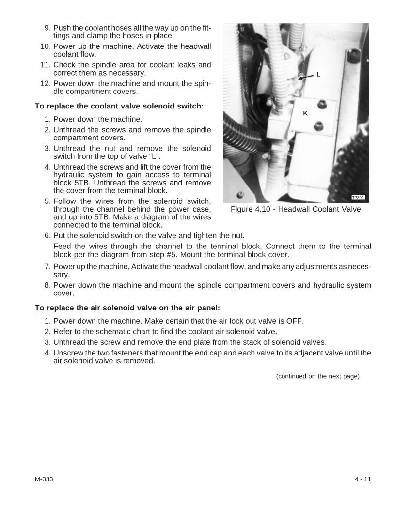
9. Push the coolant hoses all the way up on the fit-tings and clamp the hoses in place.
10. Power up the machine, Activate the headwallcoolant flow.
11. Check the spindle area for coolant leaks andcorrect them as necessary.
12. Power down the machine and mount the spin-dle compartment covers.
To replace the coolant valve solenoid switch:
1. Power down the machine.2. Unthread the screws and remove the spindle
compartment covers.3. Unthread the nut and remove the solenoid
switch from the top of valve “L”.4. Unthread the screws and lift the cover from the
hydraulic system to gain access to terminalblock 5TB. Unthread the screws and removethe cover from the terminal block.
5. Follow the wires from the solenoid switch,through the channel behind the power case,and up into 5TB. Make a diagram of the wiresconnected to the terminal block.
6. Put the solenoid switch on the valve and tighten the nut.Feed the wires through the channel to the terminal block. Connect them to the terminalblock per the diagram from step #5. Mount the terminal block cover.
7. Power up the machine, Activate the headwall coolant flow, and make any adjustments as neces-sary.
8. Power down the machine and mount the spindle compartment covers and hydraulic systemcover.
To replace the air solenoid valve on the air panel:
1. Power down the machine. Make certain that the air lock out valve is OFF.2. Refer to the schematic chart to find the coolant air solenoid valve.3. Unthread the screw and remove the end plate from the stack of solenoid valves.4. Unscrew the two fasteners that mount the end cap and each valve to its adjacent valve until the
air solenoid valve is removed.
(continued on the next page)
M-333 4 - 11
Figure 4.10 - Headwall Coolant Valve
TP309.
K
L
- NOTE -Do not remove the electrical connection or air line from valves not being replaced.
5. Unthread the screw that secures the electrical connection to the solenoid valve being replaced.Pull the connection straight up to release it from the valve.
6. Unthread the air line from the fitting on the bottom of the valve being replaced. If necessary, re-move the pneumatic fitting from the valve.
7. Use sealant to secure the fitting but do not apply it to the first few threads. Thread the air fitting tothe new valve.
8. Mount the new valve to the end piece or adjacent valve on the panel. Check the valve gasketsand replace any that are worn. Fasten each valve and gasket in place.
9. Check the gaskets and mount the other valves and end plate to the new valve.10. Support the new valve and fit the electrical connection to it. Secure the connection with its screw.
Then, fasten the air line to the fitting on the bottom of the valve.11. Power up the machine. Set the regulator to an operating pressure between 100 psi to 90 psi [5.5
to 6.3 bars].12. Press the E-Stop Reset [73] pushbutton if it is still necessary to clear “1017 Main Air Pressure
Low” alarm message from the CRT.
Coolant CatcherThe coolant catcher, Figure 4.11, returns coolant that flows through the rear of the spindle. A hose,
fastened to the coolant catcher drain, returns coolant to the reservoir (tank) through an opening in theheadwall. If the rest of the coolant system is being cleaned, the catcher and return hose should also becleaned.
To clean the spindle coolant catcher:
1. Power down the machine.2. Use a key to turn both latches and lift off the
coolant catcher cover.3. Wipe out any coolant and chips that remain in
the coolant catcher.4. Wash the catcher with a cleaner recommended
by the coolant manufacturer.5. Flush and then check the reservoir to see that
the cleaner flows into the tank.6. Clean again and/or remove the hose at the con-
nector to clean it if necessary.7. Mount the coolant catcher cover in place and
latch it.8. Clean and then ready the coolant reservoir as
described earlier in this chapter.9. Fill the tank with coolant to the FULL mark.
10. Power up the machine, Test coolant flow.
4 - 12 M-333
Figure 4.11 - Spindle Coolant Catcher
TP310
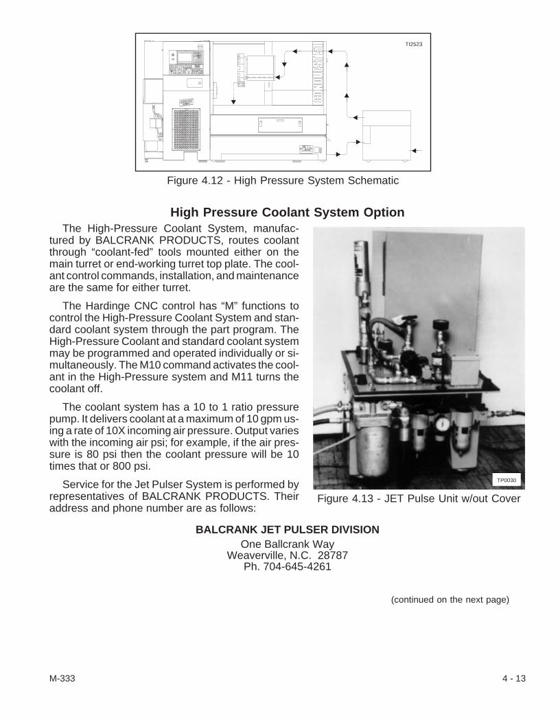
High Pressure Coolant System OptionThe High-Pressure Coolant System, manufac-
tured by BALCRANK PRODUCTS, routes coolantthrough “coolant-fed” tools mounted either on themain turret or end-working turret top plate. The cool-ant control commands, installation, and maintenanceare the same for either turret.
The Hardinge CNC control has “M” functions tocontrol the High-Pressure Coolant System and stan-dard coolant system through the part program. TheHigh-Pressure Coolant and standard coolant systemmay be programmed and operated individually or si-multaneously. The M10 command activates the cool-ant in the High-Pressure system and M11 turns thecoolant off.
The coolant system has a 10 to 1 ratio pressurepump. It delivers coolant at a maximum of 10 gpm us-ing a rate of 10X incoming air pressure. Output varieswith the incoming air psi; for example, if the air pres-sure is 80 psi then the coolant pressure will be 10times that or 800 psi.
Service for the Jet Pulser System is performed byrepresentatives of BALCRANK PRODUCTS. Theiraddress and phone number are as follows:
BALCRANK JET PULSER DIVISIONOne Ballcrank Way
Weaverville, N.C. 28787Ph. 704-645-4261
(continued on the next page)
M-333 4 - 13
Figure 4.12 - High Pressure System Schematic
TI2523
Figure 4.13 - JET Pulse Unit w/out Cover
TP0030
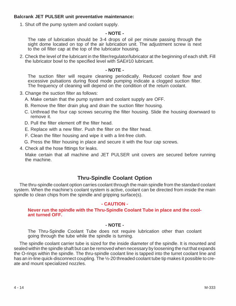
Balcrank JET PULSER unit preventative maintenance:
1. Shut off the pump system and coolant supply.
- NOTE -The rate of lubrication should be 3-4 drops of oil per minute passing through thesight dome located on top of the air lubrication unit. The adjustment screw is nextto the oil filter cap at the top of the lubricator housing.
2. Check the level of the lubricant in the filter/regulator/lubricator at the beginning of each shift. Fillthe lubricator bowl to the specified level with SAE#10 lubricant.
- NOTE -The suction filter will require cleaning periodically. Reduced coolant flow andexcessive pulsations during flood mode pumping indicate a clogged suction filter.The frequency of cleaning will depend on the condition of the return coolant.
3. Change the suction filter as follows:A. Make certain that the pump system and coolant supply are OFF.B. Remove the filter drain plug and drain the suction filter housing.C. Unthread the four cap screws securing the filter housing. Slide the housing downward to
remove it.D. Pull the filter element off the filter head.E. Replace with a new filter. Push the filter on the filter head.F. Clean the filter housing and wipe it with a lint-free cloth.G. Press the filter housing in place and secure it with the four cap screws.
4. Check all the hose fittings for leaks.Make certain that all machine and JET PULSER unit covers are secured before runningthe machine.
Thru-Spindle Coolant OptionThe thru-spindle coolant option carries coolant through the main spindle from the standard coolant
system. When the machine’s coolant system is active, coolant can be directed from inside the mainspindle to clean chips from the spindle and gripping surface(s).
- CAUTION -Never run the spindle with the Thru-Spindle Coolant Tube in place and the cool-ant turned OFF.
- NOTE -The Thru-Spindle Coolant Tube does not require lubrication other than coolantgoing through the tube while the spindle is turning.
The spindle coolant carrier tube is sized for the inside diameter of the spindle. It is mounted andsealed within the spindle shaft but can be removed when necessary by loosening the nut that expandsthe O-rings within the spindle. The thru-spindle coolant line is tapped into the turret coolant line andhas an in-line quick-disconnect coupling. The ½-20 threaded coolant tube tip makes it possible to cre-ate and mount specialized nozzles.
4 - 14 M-333

To remove the thru-spindle coolant shaft from the spindle:
1. Power down the machine.2. Unthread the screws and remove the spindle
compartment covers to gain access to thethru-spindle coolant tube and its quick-discon-nect coupling.
3. Pull back on the knurled ring and unfasten thequick-disconnect coupling in the coolant linenear the thru-spindle coolant tube.
4. Secure the rear of the thru-spindle andunthread the nut just enough turns to loosen thetube in the spindle.
5. Carefully pull the coolant tube from the spindle.
To mount the thru-spindle coolant shaft in thespindle:
6. Put a light coat of grease on the coolant shaft O-rings.7. Align the nose of the coolant tube in the spindle opening and push the tube housing into the spin-
dle as far as it will go. A flange on the rear of the housing, just in front of the nut, stops the tubefrom going in any farther.
8. Tighten the nut to expand the O-rings and secure the coolant tube in the spindle.9. Pull back on the knurled ring and fasten the quick-disconnect coupling. Check the coupling to
make certain that it is fastened securely.10. Mount the spindle drive compartment cover in place and fasten with its screws.11. Power up the machine.12. Home the axes. Test and adjust the coolant flow as necessary.
Rear Discharge Coolant SystemThe rear discharge chip conveyor pan/coolant reservoir is mounted on wheels and has a quick-dis-
connect coupling so that it can be disconnected and pulled straight out from under the machine. Infor-mation for the chip conveyor is provided in its own manual. Most other information pertaining todifferences between the rear discharge coolant system and the other coolant systems is written withinthe directions in the sections in this chapter.
- WARNING -Use a rake and suitable container to remove metal chips and shavings from thechip pan. Injury may result from attempting to remove chips without a rake. Dis-pose of the chips and shavings in an environmentally safe manner.
- CAUTION -Be careful to clear the flexible skirting while moving the coolant reservoir fromthe machine and while re-installing it in place. A second person may be neces-sary to safely hold the skirting up out of the way.
(continued on the next page)
M-333 4 - 15
Figure 4.14 - Thru-SpindleCoolant Schematic
TI2010
Turret Coolant Line
Headwall Coolant Line
CoolantDistributionBlock Coolant Line
Quick-DisconnectCoupling
Thru-SpindleCoolant Tube
Spindle

Chip removal procedure:
1. Power down the machine.2. Wait a minute to allow coolant to drain back into
the tank.3. Go to the rear of the machine, Figure 4.15.4. Locate quick-disconnect coupling “M”. Pull the
knurled ring on the coupling back and releasethe coolant hose from the fitting on the tank.
5. Clear the flexible skirting while carefully movingthe tank straight out from the rear of the ma-chine into an area that is convenient to removethe metal chips and shavings.
6. Rake the chips into a suitable container and dis-pose of them properly.
7. Lift the flexible skirting clear while re-installingthe tank to the opening under the machine.
8. Reconnect the coolant hose to the fitting on thetank by pulling back on the knurled ring, slippingthe coupling over the fitting, and releasing thering to secure it.
9. At the front of the machine, Figure 4.17, adjustthe skirting and check inside the work area tosee that coolant will drain into the chip pan.
10. Make any adjustments before powering up themachine and turning the coolant on.
Adjustable Hoses/In-Line ValvesThe rear discharge coolant system has additional
in-line valves and hoses just inside the work compart-ment to flush coolant and chips into the coolant reser-voir (tank) and chip conveyor. The adjustableSnap-Loc® hoses can be set at any length, after pow-ering down the machine, by separating any ball link,removing or adding links as necessary and re-attach-ing the separated length by pressing them togetheragain. The angle on the flexible hoses may be ad-justed by forming the links until the desired position isobtained.
Information to replace the in-line valves and/orhoses is in “Replacing the Adjustable Hoses or In-lineValves” on page 4-7 in this chapter.
4 - 16 M-333
Figure 4.15 - Rear DischargeCoolant System
TP976
N
M
Figure 4.16 - Rear Discharge(View from Right)
TP978
Figure 4.17 - Rear Discharge Coolant
TP982

- NOTES -
M-333 4 - 17

- NOTES -
4 - 18 M-333
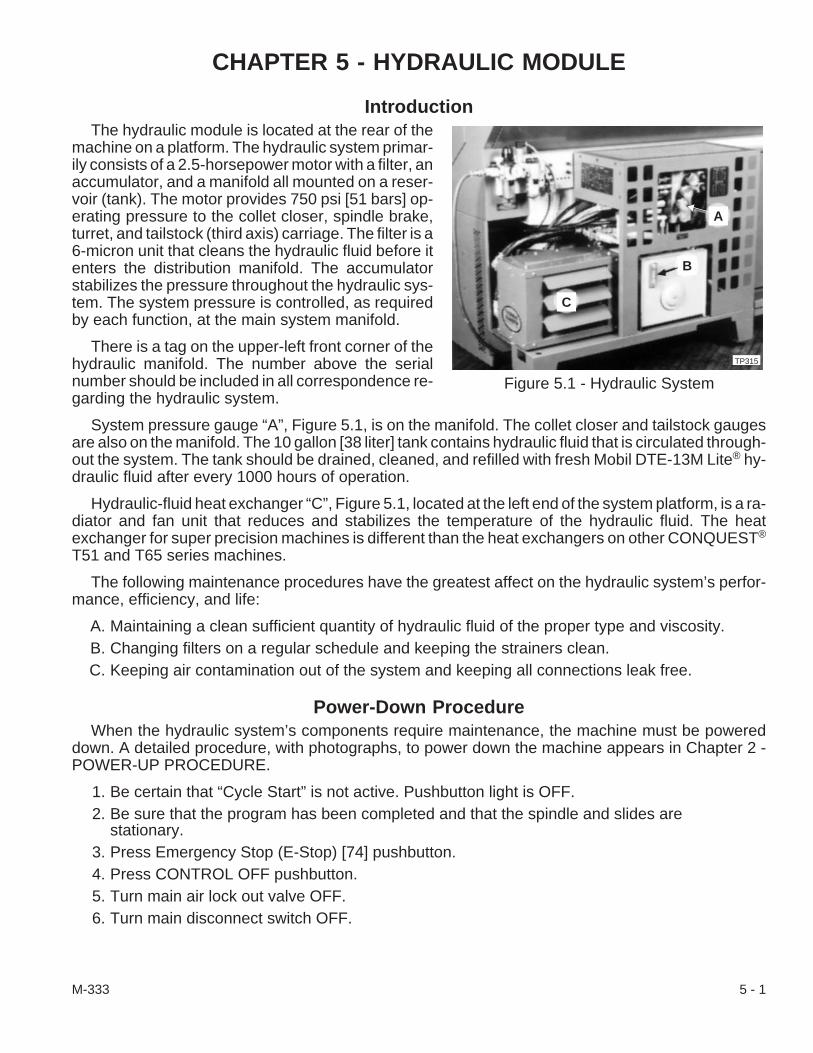
CHAPTER 5 - HYDRAULIC MODULE
IntroductionThe hydraulic module is located at the rear of the
machine on a platform. The hydraulic system primar-ily consists of a 2.5-horsepower motor with a filter, anaccumulator, and a manifold all mounted on a reser-voir (tank). The motor provides 750 psi [51 bars] op-erating pressure to the collet closer, spindle brake,turret, and tailstock (third axis) carriage. The filter is a6-micron unit that cleans the hydraulic fluid before itenters the distribution manifold. The accumulatorstabilizes the pressure throughout the hydraulic sys-tem. The system pressure is controlled, as requiredby each function, at the main system manifold.
There is a tag on the upper-left front corner of thehydraulic manifold. The number above the serialnumber should be included in all correspondence re-garding the hydraulic system.
System pressure gauge “A”, Figure 5.1, is on the manifold. The collet closer and tailstock gaugesare also on the manifold. The 10 gallon [38 liter] tank contains hydraulic fluid that is circulated through-out the system. The tank should be drained, cleaned, and refilled with fresh Mobil DTE-13M Lite® hy-draulic fluid after every 1000 hours of operation.
Hydraulic-fluid heat exchanger “C”, Figure 5.1, located at the left end of the system platform, is a ra-diator and fan unit that reduces and stabilizes the temperature of the hydraulic fluid. The heatexchanger for super precision machines is different than the heat exchangers on other CONQUEST®
T51 and T65 series machines.
The following maintenance procedures have the greatest affect on the hydraulic system’s perfor-mance, efficiency, and life:
A. Maintaining a clean sufficient quantity of hydraulic fluid of the proper type and viscosity.B. Changing filters on a regular schedule and keeping the strainers clean.C. Keeping air contamination out of the system and keeping all connections leak free.
Power-Down ProcedureWhen the hydraulic system’s components require maintenance, the machine must be powered
down. A detailed procedure, with photographs, to power down the machine appears in Chapter 2 -POWER-UP PROCEDURE.
1. Be certain that “Cycle Start” is not active. Pushbutton light is OFF.2. Be sure that the program has been completed and that the spindle and slides are
stationary.3. Press Emergency Stop (E-Stop) [74] pushbutton.4. Press CONTROL OFF pushbutton.5. Turn main air lock out valve OFF.6. Turn main disconnect switch OFF.
M-333 5 - 1
Figure 5.1 - Hydraulic System
TP315
B
C
A

Hydraulic ReservoirThe oil level should be maintained at full or near
full to ensure good system cooling, good air dissipa-tion, and overall system performance. Read sightgauge “B”, Figure 5.1.
To fill the hydraulic tank:
1. Power down the machine.2. Remove filler cap “D”, Figure 5.2, and slowly fill
the tank with Mobil DTE-13M Lite® hydraulicfluid.
3. Wait 10 minutes to allow any air in the oil to es-cape. Then, replace the filler cap.
4. Power up the machine.
Clean and Refill the Hydraulic Tank
- NOTE -Dispose of waste hydraulic oil in an environmentally safe manner.
The tank should be drained, cleaned, and refilledwith fresh Mobil DTE-13M Lite hydraulic fluid afterevery 1000 hours of operation. If the oil becomescontaminated, the source of contamination should beeliminated before the tank is refilled.
To clean and refill the tank:
1. Power down the machine.2. Unthread the screws and lift the cover from the
hydraulic module. Refer to Figure 5.2.3. Remove filler cap “D”, Figure 5.2.4. Prepare a shallow pan to drain approximately
10 gallons of hydraulic fluid from the tank.5. Reach up under the platform at “E”, Figure 5.3,
to unthread the pipe plug and drain oil from thetank.
- NOTE -The reservoir hatch is a sandwich construction with a panel inside the tank.
6. Remove reservoir hatch “F”, Figure 5.3, as follows:A. Loosen the nut in the hatch. The hatch assembly will drop and come to rest in the tank
opening.B. Lift the hatch and carefully work (pull) it from the opening.
7. Reach through the opening and wipe the remaining oil from the tank.8. Clean the tank with a solvent recommended by the hydraulic oil manufacturer.
5 - 2 M-333
Figure 5.2 - Hydraulic System withoutCover
TP3171.
D
Figure 5.3 - Hydraulic Reservoir (Tank)TP317.
F
E

9. Remove the suction strainer and clean it as follows:A. Reach into the left corner of the reservoir, grasp the strainer, and unthread it.B. Inspect the strainer for damage. Replace it as necessary.C. Clean the strainer by submerging it in a mild degreaser, pulling it out, and blow drying it
from inside.D. Inspect the strainer by shining a light into the port and visually checking it for cleanli-
ness. Clean again or replace the strainer as necessary.E. Re-install the strainer on the pump inlet. Thread the strainer on the inlet and snug it
tight. Make certain that the strainer does not touch the sides of the reservoir.10. Wipe the tank clean with a lint free cloth and let it air dry.11. Find any source of oil contamination and eliminate it before adding fresh oil.12. Put the hatch in place. Make certain that the gasket seals the opening before tightening the nut.13. Put pipe sealant or Teflon® tape on drain plug “E”, and fasten it tightly in place.14. Slowly fill the reservoir with 10 gallons [38 liter] of clean specified hydraulic oil.15. Wait 10 minutes to allow any air in the oil to escape before putting the filler cap in place and pow-
ering up the machine.16. Check the hatch and drain plug for leaks.
Hydraulic FilterThe hydraulic system filter is located to the right of the hydraulic manifold. Check the filter pressure
daily by viewing red indicator “I”, Figure 5.4. If the indicator has “popped up” (extended), try to reset itby gently pressing down on the dome. Replace the filter element after 1000 hours of operation or if theindicator doesn’t reset.
To replace the filter element:
1. Power down the machine.2. Check the red indicator to determine the condi-
tion of the filter or check the number of hours themachine has been run.
3. Unthread filter bowl “G”, Figure 5.4, from filterhead “H”, until it drops from the head.
4. Pour the oil from the filter bowl. Wipe the bowlclean with a lint free cloth.
5. Clean the bowl with solvent recommended bythe hydraulic oil manufacturer. Wipe it dry with alint free cloth.
6. Wrap the filter element in a rag and pull itstraight down to release it from the nipple in thefilter head.
7. Install a new filter element by gently pressing itonto the nipple.
(continued on the next page)
M-333 5 - 3
Figure 5.4 - Hydraulic System Filter
H
G
TP1639.
I

8. Fill half the filter bowl with fresh Mobil DTE-13M Lite® hydraulic fluid and thread it on the filterhead hand tight.
9. Reset the indicator by pressing down on its dome.10. Fill the tank with hydraulic fluid.11. Wait 10 minutes for air in the oil to dissipate and power up the machine.12. Check for hydraulic fluid leaks around the filter bowl. Tighten the bowl if necessary.
Hydraulic ManifoldThe main hydraulic manifold has the system pressure gauge, collet closer gauge, tailstock gauge,
solenoid valves, and switches mounted on it. There are no moving parts in the manifold block so thecomponents are what is checked if the collet closer, tailstock, or spindle brake fail to function. Thehoses, valves, switches and gauges are connected to the manifold with standard hydraulic fittings.Refer to Figure 5.5 to identify the hydraulic manifold components.
To replace a pressure gauge:
1. Power down the machine.2. Unthread the screws and remove the cover around the hydraulic module.3. Secure the fitting behind the gauge and unthread the gauge.4. Check the gauge for dirt particles or contaminants before replacing it.5. Use pipe dope or Teflon® tape to seal the threads of the replacement gauge.6. Hand tighten the new gauge into the manifold. Use a wrench to tighten the gauge in place only
until the numbers on the gauge can be read in an upright position.7. Power up the machine.8. Check the replacement gauge operation and for hydraulic leaks around the fitting. Tighten the
fitting as necessary.
To replace the solenoid valve(s):
The solenoid valves control whether the collet is opened (SOL 1A) or closed (SOL 1B) or if thetailstock has moved toward the spindle (minus direction, SOL 5B) or away from the spindle (plus di-rection, Home, SOL 5A).
1. Mark the valve to be replaced. Refer to Figure 5.5 for identification and valve location.2. Power down the machine.3. Unthread the screws and remove the cover around the hydraulic module.4. Unthread the screw and remove the molded LED connector (plug) from the solenoid valve being
replaced.5. Unthread the four screws that fasten the solenoid valve to the manifold.6. Mount the replacement solenoid valve on the manifold. Make certain that O-rings are in place on
the valve and that the locating pins are set before fastening the valve.7. Mount the molded LED connector on the valve and fasten it in place.8. Power up the machine.9. Test the operation of the replacement solenoid valve and/or molded LED plug.
10. Check for leaks around the valve mount on the manifold. Tighten the mounting screws as neces-sary.
5 - 4 M-333

To replace the molded LED connector(s):
1. Mark the molded LED connector to be replaced. Refer to Figure 5.5.2. Power down the machine.3. Unthread the screws and remove the cover around the hydraulic module.4. Unthread the screw and remove the molded LED connector (plug) being replaced.5. Follow the lead cable from the plug to the terminal strip.6. Make a wiring diagram so that the wires will be reconnected to the proper terminals.7. Disconnect the wires from the terminals.8. Remove the lead cable from the bundle going to the terminal strip.9. Replace the molded LED plug and cable. Use a cable tie or feed the cable into the bundle.
10. Follow the diagram from step #6 to reconnect the new wires to the terminal strip.11. Mount the molded LED connector on the solenoid valve(s) and fasten it in place.12. Power up the machine and test the operation of the replacement molded LED plug.
To replace the switches:
Faulty switches can be identified when the machine functions but the LED does not recognize thechange. Identify each switch separately as the pressure settings are different from function to func-tion.
1. Identify and mark the switch to be replaced. Refer to Figure 5.5 to identify the faulty switch and itslocation.
2. Power down the machine.3. Unthread the screws and remove the cover to the hydraulic module.4. Unthread the screw to enable the molded LED connector (plug) to be removed from the switch
being replaced.
(continued on the next page)
M-333 5 - 5
Figure 5.5 - Location of Hydraulic Manifold ComponentsTI2700
SystemPressure Sw.
Collet PressureGauge
Tailstock PressureGauge
Collet OpenPressure Switch
Collet ClosedPressure Switch
Spindle BrakePressure Switch
In-Position Switch
Tailstock,Sub-Spindle, orEnd-Working
Tailstock -, Sol 5B
Collet Closed, Sol 1B
Tailstock +, Sol 5A
Collet Open, Sol 1A
Tailstock SpeedRegulator
Spindle Free(Brake) Valve
TailstockRapid-to-Feed Valve
Left Side View Front View Right Side View
System Pressure Gauge
Collet PressureRegulator
Tailstock PressureRegulator
Main Hydraulic(Press. By-Pass) Valve
Turret Unclamp (Up) Valve

- NOTE -If the molded LED plug and cable are to be replaced, follow the directions startingon the previous page.
5. Unfasten the universal swivel fitting that secures the switch. Remove the switch from the mani-fold by turning the fitting counterclockwise.
6. Fasten the replacement switch on the manifold at least hand tight. Hold the switch in place whiletightening the universal fitting with a wrench.
7. Mount the molded LED connector on the switch and fasten it in place.8. Power up the machine.9. Test the function of the replacement switch and/or molded LED plug.
10. Check for leaks around the swivel fitting. Tighten the fitting as necessary.
To replace the coil and cartridge valves:
There are three coil and cartridge type valves on the hydraulic manifold and a turret unclamp (up)valve mounted on the turret assembly. The valves on the hydraulic manifold are for the tailstock pres-sure bypass, the tailstock speed (rapid-to-feed) select, and the spindle brake.
1. Mark the valve to be replaced. Refer to Figure 5.5 to identify the valve and its location.2. Power down the machine.3. Unthread the screws and remove the cover to the hydraulic module.4. Unthread the screw and pull the plug straight out from the coil on the valve.
- NOTE -If the molded plug is to be replaced, follow the directions “To replace the moldedLED connector(s):” starting on page 5-5.
5. Unthread the nut that fastens the coil on the cartridge valve. Pull the coil straight off the cartridgevalve.
6. Unthread the cartridge valve counterclockwise from the manifold and remove the valve from themanifold if the cartridge valve is to be replaced.
- NOTE -The cartridge valve must be replaced as a unit. There are no separate replacementparts for the cartridge valve.
7. Compare the length of the cartridge valves to be certain that the correct replacement is beingmade.
8. Put the cartridge valve into the manifold and thread it clockwise until it is tight.9. Slide the coil over the cartridge valve and fasten it by tightening the nut on the cartridge valve to
60 lb-in [6.8 N•m] torque.10. Mount the molded plug on the coil and secure it in place.11. Power up the machine.12. Test the replacement valve.13. Check for leaks around the cartridge valve fitting.14. Tighten the cartridge valve as necessary.
5 - 6 M-333

To replace the mechanical valves (pressure regulators):
Each mechanical valve must be replaced as a unit. The three mechanical valves are the collet pres-sure regulator, the tailstock pressure regulator, and the tailstock speed regulator.
1. Mark the valve to be replaced. Refer to Figure 5.5 for identification and valve location.2. Power down the machine.3. Unfasten the screws and remove the cover to the hydraulic module.4. Use a wrench on the hex surface and unthread the valve.5. Clean the replacement valve before mounting it.6. Use pipe dope or Teflon® tape to seal the threads on the replacement valve.7. Hand tighten the new valve into the manifold. Use a wrench to tighten the valve in place.8. Power up the machine.9. Test the operation of the replacement valve and adjust it as necessary.
10. Check for leaks around the valve and tighten it as necessary.
AccumulatorThe hydraulic assembly is equipped with Nitrogen charged accumulator “J”, Figure 5.6, to maintain
the hydraulic system pressure. It is mounted to a bracket on the right side of the tank. The accumulatoris precharged at the factory to approximately 460 psi [32 bars] to stabilize the hydraulic pressurethroughout the hydraulic system. The accumulator should be checked for precharge every 1000hours of machine operation or every 6 months.
An uncharged accumulator is indicated by slowoperation of the machine cycle. The precharge canbe checked, after making sure that the machine ispowered down, by using a test gauge on the accumu-lator.
Use only DRY INDUSTRIAL GRADE NITROGENto precharge the accumulator. Industrial grade nitro-gen can be purchased at a quality pipe welding sup-ply house.
To adjust the accumulator precharge:
1. Power-up the machine.2. Observe the main system pressure gauge. If
the system gauge does not read 750 psi [52bars], adjust the pressure as follows:A. Unthread the jam nut on stem “K”, Figure
5.6.B. Adjust the stem (thread in - increase the
pressure; unthread - decrease the pres-sure) until the system gauge reads 750psi [52 bars].
C. Tighten the jam nut to secure the stem.
(continued on the next page)
M-333 5 - 7
Figure 5.6 - Hydraulic System Accumulator
K
J
LTP1639.
3. Power down the machine.
- NOTES -The normal system precharge pressure reading should be from 420 to 470 psi [29to 33 bars].
If the precharge pressure is less than 420 psi [29 bars], the accumulator must beprecharged to between 460 and 470 psi [approximately 32 bars]. If the prechargepressure is more than 470 psi [33 bars], the accumulator must be discharged tothe 470 to 460 psi [approximately 32 bars] range.
4. Remove the cover from accumulator valve stem (Shrader valve) “L”, Figure 5.6. Install a testvalve and pressure gauge unit.
5. Turn the handle on the test valve clockwise until the gauge indicates pressure.To precharge the accumulator:
- NOTE -Charge the accumulator with dry Nitrogen gas.
A. Turn the handle on the test valve counterclockwise to close the valve.B. Attach the Nitrogen cylinder hose connection to the accumulator test valve.C. Turn the Nitrogen cylinder valve ON and turn the test valve clockwise to open it. Read
the gauge until 460 to 470 psi [approximately 32 bars] precharge pressure is met.D. Close the test valve and shut the Nitrogen cylinder valve OFF.E. Disconnect the Nitrogen cylinder hose from the test valve.
To discharge pressure from the accumulator:
A. Make certain that the hydraulic system oil pressure is zero.B. Depress the valve stem slowly with a hand tool or use the test valve release to lower
the pressure until it is within the 470 to 460 psi [approximately 32 bars] range.6. Repeat steps #1 through #5 until the proper accumulator precharge pressure is met.7. Turn the handle on the test valve counterclockwise to close the valve.8. Disconnect the test valve and pressure gauge unit. Install the cover on the accumulator valve
stem.
5 - 8 M-333

- NOTES-
M-333 5 - 9

- NOTES-
5 - 10 M-333

CHAPTER 6 - LUBRICATION
IntroductionThe CONQUEST® T51 and CONQUEST T65 series machine lubricator is mounted on the left end
of the machine at the right of the spindle compartment; some machines have a sheetmetal guard. Lu-brication is accomplished through a TRABON® lubrication system, Figure 6.1. The system lubricatesthe ball screws, the bearings on the linear guideways, and the third-axis way. The only other lubrica-tion requirement is provided by the hydraulic system to the bearings in the collet closer. If there is nolower axis on the machine, that lubrication port is plugged at the main distribution manifold.
The lubricator is active any time the CNC control ison. When the lubrication system requires mainte-nance, the machine must be powered down. A de-tailed procedure to power it down appears in Chapter2 - POWER-UP PROCEDURE.
Power-Down Procedure1. Be certain that “Cycle Start” is not active. The
pushbutton light should be off.2. Be sure that the program has been completed
and that the spindle and slides are stationary.3. Press Emergency Stop (E-Stop) [74]
pushbutton.4. Press CONTROL OFF pushbutton.5. Turn main air lock out valve OFF.6. Turn main disconnect switch OFF.
Lubrication OilThe lubrication oils that Hardinge, Inc. recommends for use on the machines have been thoroughly
tested and qualified. Other oils may not contain certain additive packages needed for proper lubrica-tion and performance from the oil. The additive packages may include rust and corrosion inhibitors,anti-wear compounds, defoamants, etc., which have been blended specifically for that application. Al-though many companies offer “similar” oils, these oils may not contain the needed additives to ensuremaximum performance and protection of the Hardinge machines.
Lubricator ConsumptionThe run time for one full lubricator reservoir (tank) is approximately 52 hours. It should be noted that
all times are approximate and that variations on an individual machine could be up to ±10% from thetime listed. If actual lubrication consumption is greater or less than the acceptable range given, checkthe system for leaks, kinked hoses, oil type, and TRABON master and secondary divider valves (feed-ers).
M-333 6 - 1
Figure 6.1 - Lubricator Location andSpindle Compartment Access Cover
A
TP3173.

The reservoir contains approximately 6 liters [1.6gallons] of Mobil Vactra® #2 oil when filled. TheTRABON® feeders limit the amount of oil used per cy-cle. Oil is sent through the system by a motor-drivengear pump. The pump cycle time is controlled by ma-chine software and is preset at Hardinge. The lubri-cation pump cycles every 1.66 minutes; however,when the tailstock is turned off, the tailstock receiveslubrication once every 50 minutes (30 cycles).
The machine software detects the following infor-mation:
A.Pump malfunctionB.Defective pressure switchC.Most crimped or broken lubricator lines.
If the cycle software senses a failure in the lubrica-tion system, a “Lube Fail, 5 Min to Shutdown” mes-sage will be displayed and setup mode (Block byBlock) is activated to allow the tool to be moved fromthe workpiece. After 5 minutes, the machine goesinto JOG mode, then it shuts down, and a “Lube Sys-tem Failure” message will be displayed if the lubrica-tion system malfunction is not corrected.
Lubricator RefillCheck the oil level daily. The oil level can be seen by looking at the sight gauge. The lubricator tank
can be refilled at anytime that oil is needed, even while the machine is in operation. If the lubricator islow on oil, the following conditions exist:
A. “Lube Low Refill” is displayed and single mode LED will flash but automatic operation is still al-lowed.
B. When the tank is not refilled within the next 25 minutes, the machine is forced into Block by Blockoperation.
C. If the tank is not filled after 5 more minutes, the machine will shut down with the JOG modelocked on and the “Lube System Failure” message displayed.
D. When the machine is powered up and the “Low Lube Refill” message is displayed, the JOGmode is locked on. Fill the lubricator tank to clear this message and re-enable the lubricationsystem.
To fill the lubricator tank:
1. Wipe away any chips, oil, and dirt from the tank cover.
- NOTE -Leave the filler tube screen in place.
2. Lift filler cap “B”, Figure 6.2 and fill the tank with Mobil Vactra #2 oil.3. Close the cap and continue with maintenance or operation.
6 - 2 M-333
Figure 6.2 - TRABON Lubricator
B
C
TP801.
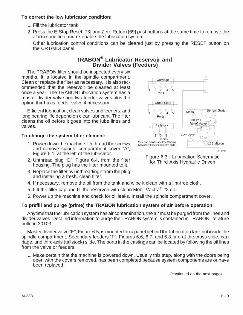
To correct the low lubricator condition:
1. Fill the lubricator tank.2. Press the E-Stop Reset [73] and Zero Return [69] pushbuttons at the same time to remove the
alarm condition and re-enable the lubrication system.Other lubrication control conditions can be cleared just by pressing the RESET button onthe CRT/MDI panel.
TRABON® Lubricator Reservoir andDivider Valves (Feeders)
The TRABON filter should be inspected every sixmonths. It is located in the spindle compartment.Clean or replace the filter as necessary. It is also rec-ommended that the reservoir be cleaned at leastonce a year. The TRABON lubrication system has amaster divider valve and two feeder valves plus theoption third-axis feeder valve if necessary.
Efficient lubrication, clean valves and feeders, andlong bearing life depend on clean lubricant. The filtercleans the oil before it goes into the lube lines andvalves.
To change the system filter element:
1. Power down the machine. Unthread the screwsand remove spindle compartment cover “A”,Figure 6.1, at the left of the lubricator.
2. Unthread plug “D”, Figure 6.4, from the filterhousing. The plug has the filter mounted to it.
3. Replace the filter by unthreading it from the plugand installing a fresh, clean filter.
4. If necessary, remove the oil from the tank and wipe it clean with a lint-free cloth.5. Lift the filler cap and fill the reservoir with clean Mobil Vactra® #2 oil.6. Power up the machine and check for oil leaks. Install the spindle compartment cover.
To prefill and purge (prime) the TRABON lubrication system of air before operation:
Anytime that the lubrication system has air contamination, the air must be purged from the lines anddivider valves. Detailed information to purge the TRABON system is contained in TRABON literaturebulletin 30103.
Master divider valve “E”, Figure 6.5, is mounted on a panel behind the lubrication tank but inside thespindle compartment. Secondary feeders “F”, Figures 6.6, 6.7, and 6.8, are at the cross slide, car-riage, and third-axis (tailstock) slide. The ports in the castings can be located by following the oil linesfrom the valve or feeders.
1. Make certain that the machine is powered down. Usually this step, along with the doors beingopen with the covers removed, has been completed because system components are or havebeen replaced.
(continued on the next page)
M-333 6 - 3
Figure 6.3 - Lubrication Schematicfor Third Axis Hydraulic Driven
Cross Slide
Tailstock
Ports
Ports
Low Level
Mesh
125 Micron
TI 2709
1
1
2
2
3
2
4
3 4
1 4
5
5Ports
Sensor Switch
3
Carriage
300 PSIRelief Valve
Most Sub-Spindle and End-WorkingSecondary Feeders have five ports.
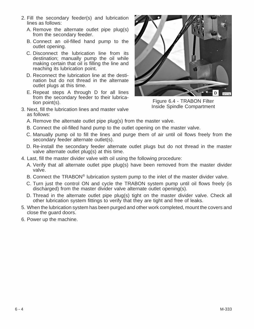
2. Fill the secondary feeder(s) and lubricationlines as follows:A. Remove the alternate outlet pipe plug(s)
from the secondary feeder.B. Connect an oil-filled hand pump to the
outlet opening.C. Disconnect the lubrication line from its
destination; manually pump the oil whilemaking certain that oil is filling the line andreaching its lubrication point.
D. Reconnect the lubrication line at the desti-nation but do not thread in the alternateoutlet plugs at this time.
E. Repeat steps A through D for all linesfrom the secondary feeder to their lubrica-tion point(s).
3. Next, fill the lubrication lines and master valveas follows:A. Remove the alternate outlet pipe plug(s) from the master valve.B. Connect the oil-filled hand pump to the outlet opening on the master valve.C. Manually pump oil to fill the lines and purge them of air until oil flows freely from the
secondary feeder alternate outlet(s).D. Re-install the secondary feeder alternate outlet plugs but do not thread in the master
valve alternate outlet plug(s) at this time.4. Last, fill the master divider valve with oil using the following procedure:
A. Verify that all alternate outlet pipe plug(s) have been removed from the master dividervalve.
B. Connect the TRABON® lubrication system pump to the inlet of the master divider valve.C. Turn just the control ON and cycle the TRABON system pump until oil flows freely (is
discharged) from the master divider valve alternate outlet opening(s).D. Thread in the alternate outlet pipe plug(s) tight on the master divider valve. Check all
other lubrication system fittings to verify that they are tight and free of leaks.5. When the lubrication system has been purged and other work completed, mount the covers and
close the guard doors.6. Power up the machine.
6 - 4 M-333
Figure 6.4 - TRABON FilterInside Spindle Compartment
D TP774.

To replace master divider valve “E”, and/or secondary feeders “F” - Figures 6.5, 6.6, 6.7,and 6.8:
If it is ever necessary to replace a valve or feeder section, each has a reference number stampedon its face; however, Hardinge recommends replacing them as a unit.
Master divider valve sections “E”, are mounted on a manifold while secondary feeder sections “F”,are mounted together (stacked) between an inlet section and an end section fastened with tie rods. Allsections are sealed by O-rings.
1. Move the axis being worked on to a convenientwork position. Move the third axis toward thespindle to the solid stop. Move the cross slidetoward the spindle centerline (-X) and over nearthe rear access cover; move the carriage to-ward the spindle (-Z).
2. Power down the machine.3. Open the main door and access covers. Use a
key to unfasten two latches and remove the ac-cess covers as necessary.
4. Unthread the screws and remove the way cov-ers or motor covers.
- NOTE -Check the condition of the O-rings andmake certain that an O-ring seals eachoil passageway.
5. On the master divider valve, disconnect the lu-brication line(s) only to the section being re-placed; unthread both valve section mountingscrews and remove just the valve section beingreplaced.On the secondary feeder valves, disconnectthe lubrication line(s) to the section being re-placed; unthread the tie rod nuts and, beingcareful of the O-rings, remove the secondaryfeeder section(s) to the section being re-placed. It may be necessary to unthread thescrews and remove the secondary feederunit from the mounting location.
6. Verify that the replacement section is the sameas the section removed and check the conditionof the O-rings. Replace the O-rings as neces-sary.
7. Place an O-ring at each oil passageway andmount the new valve either on the manifold orstacked. Tighten the threads and mount theunit if necessary.
8. Refasten the lubricator line(s). Prefill and purge the lubrication system.9. Mount the covers and close the guard doors.
10. Power up the machine.
M-333 6 - 5
Figure 6.5 - TRABON® MasterDivider Valve
ETP774.
Figure 6.6 - TRABON CarriageSecondary Feeder
F
TP776.

Replace the LubricatorReplace the lubricator as a unit if any of the lubricator mechanisms such as the motor, pump, or
sensor fail or become damaged.
1. Power down the machine.2. Disconnect the oil line from the lubricator.3. Unthread knurled nuts that secure the grom-
mets which seal the electrical cables.4. Loosen the screws that fasten the cover to elec-
trical junction box “G”, Figure 6.9, and lift off thecover.
5. Make a diagram of the electrical wire connec-tions and connection for sensor wire “H”. Thiswill be important to follow when reconnectingthe replacement lubricator.
6. Disconnect the wires and remove the cablesfrom the junction box and fittings.
7. Unthread two nuts that mount the lubricator tothe bracket. It may be necessary to unthreadthe screws on either side of the tank and re-move the reservoir to ease the removal of thelubricator. Replace the lubricator and mount thenew lubricator to the bracket.
8. Feed the cables into the junction box and con-nect the wires per step #5. Cover the junctionbox. Make certain that the grommets are inplace and then seal them by tightening theknurled nuts.
6 - 6 M-333
Figure 6.7 - TRABON Cross SlideSecondary Feeder
F
TP775. Figure 6.8 - TRABON® Third-AxisSecondary Feeder
F
TP777.
Figure 6.9 - TRABON Lubricator
TP3173.
G
H
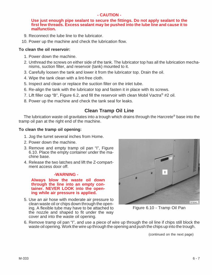
- CAUTION -Use just enough pipe sealant to secure the fittings. Do not apply sealant to thefirst few threads. Excess sealant may be pushed into the lube line and cause it tomalfunction.
9. Reconnect the lube line to the lubricator.10. Power up the machine and check the lubrication flow.
To clean the oil reservoir:
1. Power down the machine.2. Unthread the screws on either side of the tank. The lubricator top has all the lubrication mecha-
nisms, suction filter, and reservoir (tank) mounted to it.3. Carefully loosen the tank and lower it from the lubricator top. Drain the oil.4. Wipe the tank clean with a lint-free cloth.5. Inspect and clean or replace the suction filter on the inlet tube.6. Re-align the tank with the lubricator top and fasten it in place with its screws.7. Lift filler cap “B”, Figure 6.2, and fill the reservoir with clean Mobil Vactra® #2 oil.8. Power up the machine and check the tank seal for leaks.
Clean Tramp Oil LineThe lubrication waste oil gravitates into a trough which drains through the Harcrete® base into the
tramp oil pan at the right end of the machine.
To clean the tramp oil opening:
1. Jog the turret several inches from Home.2. Power down the machine.3. Remove and empty tramp oil pan “I”, Figure
6.10. Place the empty container under the ma-chine base.
4. Release the two latches and lift the Z-compart-ment access door off.
-WARNING -Always blow the waste oil downthrough the line into an empty con-tainer. NEVER LOOK into the open-ing while air pressure is applied.
5. Use an air hose with moderate air pressure toclean waste oil or chips down through the open-ing. A flexible tube may have to be attached tothe nozzle and shaped to fit under the waycover and into the waste oil opening.
6. Remove tramp oil pan “I”, and use a piece of wire up through the oil line if chips still block thewaste oil opening. Work the wire up through the opening and push the chips up into the trough.
(continued on the next page)
M-333 6 - 7
Figure 6.10 - Tramp Oil Pan
I
TP3041.

- CAUTION -Use a cloth to remove the chips from the trough. Never use an air blast and do notuse bare hands to remove the chips.
7. Wipe the chips from the trough with a rag and put the oil pan under the machine base.8. Use an air hose with moderate air pressure to clean the waste oil opening again after using the
wire to clear it.9. Remove the oil pan and clean any debris from it. Replace the pan under the machine.
10. Remount the Z-compartment access door. Fasten both latches to secure the door.11. Check the oil level in the lubrication reservoir. Fill the reservoir, if necessary, with Mobil Vactra®
#2 oil.12. Power up the machine.
- NOTES -
6 - 8 M-333

CHAPTER 7 - HEADSTOCK and SPINDLE DRIVE
IntroductionHeadstock and spindle assembly “A”, Figure 7.1, is mounted to a steel insert in the Harcrete® poly-
mer composite base. The headstock has a solid, ribbed, cast-iron housing that dissipates heat andsupports the spindle assembly. The headstock assembly cannot be disassembled in the field.
The standard spindle is an ANSI A2-6" 20C collet design that permits bar work up to 2 inches [51mm] diameter, chucking work up to 6 inches [152 mm] diameter with step chucks, and chucking workup to 8 inch [203 mm] diameter with a Thru-Hole® jaw chuck.
The CONQUEST® T51 machine with “Big-Bore”option and the CONQUEST T65 series machine fea-ture an ANSI A2-8" 25C collet design that permits barwork up to 2.5 inches [65 mm] diameter, step chuckwork up 8 inches [203 mm] diameter, and Thru-Holejaw chuck work up to 10 inches [254 mm].
The reliable, AC, digital spindle motor requiresminimal maintenance due to its fan cooled,brushless, and permanently sealed and lubricateddesign. Drive vibration is minimized through the useof a vee-belt. An external, hydraulic brake is mountedto the headstock while the brake disc is mounted di-rectly to the spindle pulley.
Power-Down ProcedureWhenever the spindle compartment cover or coolant catcher access cover is opened the machine
must be powered down. A detailed procedure to power down and lock out the machine appears inChapter 2 - Power-Up Procedure.
1. Be certain that “Cycle Start” is not active. Pushbutton light is OFF.2. Be certain that the program has been completed and that the spindle and slides are stationary.3. Press the Emergency Stop (E-Stop) [74] pushbutton.4. Press the CONTROL OFF pushbutton.5. Turn off and lock out the main air lock-out valve.6. Turn off and lock out the main disconnect switch.
M-333 7 - 1
Figure 7.1 - Headstock
A
TP332.
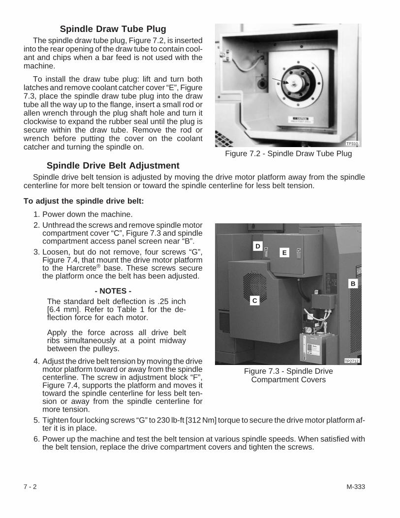
Spindle Draw Tube PlugThe spindle draw tube plug, Figure 7.2, is inserted
into the rear opening of the draw tube to contain cool-ant and chips when a bar feed is not used with themachine.
To install the draw tube plug: lift and turn bothlatches and remove coolant catcher cover “E”, Figure7.3, place the spindle draw tube plug into the drawtube all the way up to the flange, insert a small rod orallen wrench through the plug shaft hole and turn itclockwise to expand the rubber seal until the plug issecure within the draw tube. Remove the rod orwrench before putting the cover on the coolantcatcher and turning the spindle on.
Spindle Drive Belt AdjustmentSpindle drive belt tension is adjusted by moving the drive motor platform away from the spindle
centerline for more belt tension or toward the spindle centerline for less belt tension.
To adjust the spindle drive belt:
1. Power down the machine.2. Unthread the screws and remove spindle motor
compartment cover “C”, Figure 7.3 and spindlecompartment access panel screen near “B”.
3. Loosen, but do not remove, four screws “G”,Figure 7.4, that mount the drive motor platformto the Harcrete® base. These screws securethe platform once the belt has been adjusted.
- NOTES -The standard belt deflection is .25 inch[6.4 mm]. Refer to Table 1 for the de-flection force for each motor.
Apply the force across all drive beltribs simultaneously at a point midwaybetween the pulleys.
4. Adjust the drive belt tension by moving the drivemotor platform toward or away from the spindlecenterline. The screw in adjustment block “F”,Figure 7.4, supports the platform and moves ittoward the spindle centerline for less belt ten-sion or away from the spindle centerline formore tension.
5. Tighten four locking screws “G” to 230 lb-ft [312 Nm] torque to secure the drive motor platform af-ter it is in place.
6. Power up the machine and test the belt tension at various spindle speeds. When satisfied withthe belt tension, replace the drive compartment covers and tighten the screws.
7 - 2 M-333
Figure 7.2 - Spindle Draw Tube PlugTP310.
Figure 7.3 - Spindle DriveCompartment Covers
C
DE
TP2712.
B

Spindle Drive Belt ReplacementThe spindle drive belt tension is adjusted by moving the drive motor platform after the belt has been
replaced. If the standard pulley is being changed to a hi-torque pulley, the belt must also be changed.
To replace the spindle drive belt:
1. Power down the machine.2. Gain access to the spindle compartment:
A. Loosen the clamp and remove coolanthose from the coolant catcher drain.
B. Unthread the screws and remove spindlemotor compartment cover “C”, Figure 7.3,and spindle compartment access panel“B”.
C. Unthread the mounting screws and lift offthe last spindle compartment cover.
3. Loosen, but do not remove, four screws “G”,Figure 7.4, that mount the drive motor platformto the Harcrete® base. These screws securethe drive motor platform once the belt has beenadjusted.
4. Turn the screw in adjustment block “F” clock-wise until enough tension is relieved from thebelt to allow it to be removed from the drive pul-ley.
5. Have a can ready to catch the hydraulic fluid.Disconnect the collet closer hydraulic line andcollet open line.
6. Unfasten the collet closer hydraulic fluid returnline.
7. Unthread two screws “H” and slide (remove)brake “I” from the brake disc and brake spacerblock.
8. Unfasten the collet closer bracket.
(continued on the next page)
M-333 7 - 3
Figure 7.4 - Drive Motor Platform Bolts
G
F
G G
TP3217.
Figure 7.5 - Spindle Brake
I
HTP52.
Conquest Motor T51 - 22P T51SP - 12S High Torque/ T65 - 22S
Deflection .25" [6.4 mm] .25" [6.4 mm] .25" [6.4 mm] .25" [6.4 mm]
Force - New Belt 30-35lb [133-156N] 25-30lb [111-133] 40-45lb [178-200N] 35-40lb [156-178N]
Force - Used Belt 25-30lb [111-133N] 20-25lb [89-111N] 35-40lb [156-178N] 30-35lb [133-156N]
Table 1 - Spindle Drive Belt Deflection Forces
9. If the machine is equipped with the 2-1/2 degree spindle orient option or the C-axis option, care-fully loosen and remove these components.
10. Remove the worn belt from the spindle pulley. Put the replacement belt on the pulley. The stan-dard belt uses the three pulley grooves closest to the headstock.
- NOTES -The belt deflection specification used on standard machines is .25 inch [6.4 mm].The deflection force for the Hi-Torque and “Big-Bore” options is 14 to 17 pounds[62 to 76 N]. Refer to Table 1.
Apply force across all drive belt ribs simultaneously and at a point midway betweenthe pulleys.
11. Adjust belt tension to within specification by turning adjustment block screw “F”, Figure 7.4,counterclockwise so that the drive motor platform moves away from the spindle centerline. Finetune the belt adjustment by threading the adjustment block screw either clockwise or counter-clockwise.
12. Tighten four locking screws “G” to a torque of 230 lb-ft [312 Nm] to secure the platform afterproper belt tension has been met.
13. If the machine is equipped with the 2-1/2 degree spindle orient option or the C-axis option, care-fully mount these components.
14. Fasten both hydraulic lines, Figure 7.5, to their respective fittings on the collet closer and con-nect the fluid return line.
15. Fasten the collet closer bracket in place.16. Wipe brake “I” clean. Make sure that the O-rings are in place; and then, mount the brake on the
brake spacer block. Alternately tighten mounting screws “H” to 30 lb-ft [41 Nm] torque.17. Power up the machine and bleed the brake as follows:
A. Loosen the “grease-fitting” nipple on each side of the brake.B. Tighten the lower nipple and then the upper nipple as air escapes and hydraulic fluid
flow becomes steady.C. Power down the machine if either nipple leaks. Remove the leaking nipple; clean and
re-install it.D. Power up the machine and bleed the brake again.
18. Test the brake as follows:A. Press the JOG [4] pushbutton; and then, press the Spindle JOG [26] pushbutton.B. Watch the gap between the brake pad and brake disc as the spindle slowly turns.C. Press the Spindle FREE [25] pushbutton to have the brake pads disengage the disc.
Press it again to engage the brake.19. Mount the spindle motor compartment covers and spindle compartment access panel.
Attach the coolant drain hose to the coolant catcher and install coolant catcher cover “D”,Figure 7.3.
20. Test the machine at various spindle speeds. When satisfied with the spindle drive belt tension,install the spindle motor cover.
7 - 4 M-333
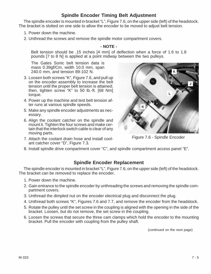
Spindle Encoder Timing Belt AdjustmentThe spindle encoder is mounted in bracket “L”, Figure 7.6, on the upper side (left) of the headstock.
The bracket is slotted on one side to allow the encoder to be moved to adjust belt tension.
1. Power down the machine.2. Unthread the screws and remove the spindle motor compartment covers.
- NOTE -Belt tension should be .15 inches [4 mm] of deflection when a force of 1.6 to 1.8pounds [7 to 8 N] is applied at a point midway between the two pulleys.
The Gates Sonic belt tension data ismass 0.39gf/Cm, width 10.0 mm, span240.0 mm, and tension 89-102 N.
3. Loosen both screws “K”, Figure 7.6, and pull upon the encoder assembly to increase the belttension until the proper belt tension is attained;then, tighten screw “K” to 50 lb.-ft. [68 Nm]torque.
4. Power up the machine and test belt tension af-ter runs at various spindle speeds.
5. Make any spindle encoder adjustments as nec-essary.
6. Align the coolant catcher on the spindle andmount it. Tighten the four screws and make cer-tain that the interlock switch cable is clear of anymoving parts.
7. Attach the coolant drain hose and install cool-ant catcher cover “D”, Figure 7.3.
8. Install spindle drive compartment cover “C”, and spindle compartment access panel “E”.
Spindle Encoder ReplacementThe spindle encoder is mounted in bracket “L”, Figure 7.6, on the upper side (left) of the headstock.
The bracket can be removed to replace the encoder.
1. Power down the machine.2. Gain entrance to the spindle encoder by unthreading the screws and removing the spindle com-
partment covers.3. Unthread the dimpled nut on the encoder electrical plug and disconnect the plug.4. Unthread both screws “K”, Figures 7.6 and 7.7, and remove the encoder from the headstock.5. Rotate the pulley until the set screw in the coupling is aligned with the opening in the side of the
bracket. Loosen, but do not remove, the set screw in the coupling.6. Loosen the screws that secure the three cam clamps which hold the encoder to the mounting
bracket. Pull the encoder with coupling from the pulley shaft.
(continued on the next page)
M-333 7 - 5
Figure 7.6 - Spindle Encoder
TP339.
J
K
K
L

7. Measure where the coupling is on the encodershaft; then, loosen the set screw and removethe coupling from the shaft. Mount the couplingon the new encoder.
8. Align the coupling opening with the pulley shaft,make certain that the set screw will align withthe opening in the side of the bracket andmount the encoder on the bracket. Put the camclamp fully into the groove on the encoder andtighten the screws.
9. Tighten the coupling set screw to the encodershaft.
10. Remount the encoder assembly on theheadstock. Slip the spindle timing belt over thepulley and center it. Mount the encoder bracketin place and fasten with both screws, hand tight.
- NOTE -Belt tension should be .15 inches [4 mm] of deflection when a force of 1.6 to 1.8pounds [7 to 8 N] is applied at a point midway between the two pulleys.
The Gates Sonic belt tension data is mass 0.39gf/Cm, width 10.0 mm, span 240.0mm, and tension 89-102 N.
11. If necessary, loosen screw(s) “K”, to pivot the bracket and adjust the belt tension. Retighten thescrew(s) when the proper belt tension is set.
12. Align the pin on the encoder electrical plug and connect the plug to the encoder. Thread the dim-pled nut tight onto the connector.
- WARNING -Shut down the power to the machine each time the encoder needs to be adjusted.
- NOTE -Usually there is no adjustment to the spindle encoder because it is reading the rel-ative position of the spindle through the full 360 degrees.
If the machine has the 2-1/2 degree spindle orient option, re-orient the spindle perthe information at the end of the next section, page 7-9.
13. Power up the machine. Test the encoder at various rpm while observing the belt and checkingthe new encoder.
14. When satisfied with the new encoder and belt tension, mount the spindle compartment covers.Tighten the screws.
7 - 6 M-333
Figure 7.7 - Encoder Mountedon Top of Headstock
TP340.
M
KJL

Spindle Encoder Timing Belt ReplacementThe spindle encoder is mounted in bracket “L”, Figures 7.6 and 7.7, on the upper side (left) of the
headstock. The spindle encoder timing belt replacement requires that the spindle coolant catcher,collet closer, brake disc, and spindle drive belt be removed.
1. Power down the machine.2. Gain entrance to the spindle compartment from
both sides of the corner by unthreading thescrews and removing spindle compartmentcovers “C” and “D”, Figure 7.3, and spindlecompartment access panel “B”.
3. Loosen, but do not remove, four screws “G”,Figure 7.4, that mount the spindle drive motorplatform to the Harcrete base.
4. Spindle drive belt tension is released by movingthe motor platform closer to the spindle center-line. Turn the screw in adjustment block “F”,clockwise. Enough tension should be off thebelt to allow it to be removed from the spindlepulley in step#9.
5. In order to remove the belt from the spindle; re-move the coolant catcher, unfasten colletcloser bracket, and; then, tag and disconnectthe following lines for identification from the col-let closer:A. Unthread the universal nuts to disconnect both the collet open hydraulic line “O”, and
collet close line “N”, fittings, Figure 7.8.B. Then disconnect hydraulic fluid return line “P”, from the collet closer connector.
6. Unthread screws “Q”, and follow the directions in Chapter 8 - COLLET CLOSER to remove thecloser.
- NOTE -It is not necessary to unfasten the hydraulic brake line from the brake whenlowering the brake from the disc.
7. Spindle brake “I”, Figure 7.5, can be removed from the brake disc by unthreading both mountingscrews “H”, and sliding (removing) the brake from the disc.
8. Remove the brake disc from the spindle pulley as follows:A. Make a location reference mark from the brake disc to the spindle drive pulley for reas-
sembly.B. Unthread the screws and slide the disc straight off the pulley. Do not remove the spindle
drive pulley.9. Slide the spindle drive belt from the drive motor pulley then the spindle pulley. Refer to step#4 if
the belt tension needs to be loosened more for removal.10. Loosen both screws “K”, Figures 7.6 and 7.7, to loosen the encoder belt from the pulleys. Slide
the encoder belt from the encoder and then the spindle pulley.
(continued on the next page)
M-333 7 - 7
Figure 7.8 - Collet Closer
N
O
Q
PTP2214.

- NOTE -Belt tension should be .15 inches [4 mm] of deflection when a force of 1.6 to 1.8pounds [7 to 8 N] is applied at a point midway between the two pulleys.
The Gates Sonic belt tension data is mass 0.39gf/Cm, width 10.0 mm, span 240.0mm, and tension 89-102 N.
11. Replace the spindle encoder timing belt. Adjust the belt tension and tighten mounting screws“K”.
- NOTES -The standard belt deflection is .25 inch [6.4 mm]. Refer to Table 1 for the deflec-tion force for each drive motor.
Apply the force across all drive belt ribs simultaneously at a point midway betweenthe pulleys.
12. Slide the spindle drive belt onto both pulleys. The drive belt goes on the three grooves closest tothe headstock. Adjust the belt tension and tighten all four drive motor platform screws.
13. Slide the brake disc onto the spindle drive pul-ley. Align the locating reference mark fromstep#8.A and mount the disc brake in place asfollows:A. Indicate the inside of the bore, Figure 7.9.
Adjust the disc so that there is no morethan .0005 inch [.0127 mm] runout.
B. Indicate the inside face of the disc, Fig-ures 7.9. Again adjust the disc so thatthere is no more than .0005 inch [.0127mm] runout.
C. Apply Loctite® #242 threadlocker to thethreads and fasten screws, “H”, to 25 lb-ft.[34 Nm] torque.
D. Re-indicate both runouts again.14. After the disc is in place, mount the brake to its
spacer (mounting) block. Alternately tighteneach brake mounting screw to 30 lb-ft [41 Nm]torque.
15. Follow the detailed directions in Chapter 8 -COLLET CLOSER to remount the closer andalso refer to Figure 7.8.
16. Connect the collet closer hydraulic lines per the tags on the lines from step #5.17. Align the coolant catcher on the spindle and mount it. Tighten the four screws and make certain
that the interlock switch cable is clear of any moving parts.18. Attach the coolant drain hose and install the coolant catcher cover.
- WARNING -Power down the machine each time anything in the spindle compartment needsto be adjusted.
19. Power up the machine and test the belts at various rpm. When satisfied with the new encoderand belt tension, mount the spindle compartment covers. Tighten the screws.
7 - 8 M-333
Figure 7.9 - Spindle Brake Disc Alignment
TP1763
.0005" [.0127mm]T.I.R. maximum
.0005" [.0127mm]T.I.R. maximum
- NOTE -The spindle is oriented when the scribed line on the outer edge of the spindle andthe scribed line on the edge of the spindle front cap are aligned.
20. If the machine has the 2-1/2 degree spindle orient option or C-axis option, re-orient the spindleas follows:A. Turn the Program Protect key OFF.B. Press the Machine Mode MDI pushbutton.C. Press the PROG key until Program (MDI) appears.D. Enter B 0 and press the EOB key. To enter the B, press the SHIFT key and then press
the B key.E. Press CYCLE START [72] pushbutton. Spindle will orient.F. Observe the scribed lines on the outer edge of the spindle and the edge of the spindle
front cap. If the lines are aligned, then the spindle is oriented. If the lines are notaligned, continue with the following instructions.
G. Press the RESET key on the MDI panel.H. Change parameter 4077 S1 as follows:
1. Press the OFFSET SETTING key.2. Then press the SETING soft key to display the Setting (HANDY) page.3. Press the PAGE down ( � ) or up ( � ) until the cursor is at Parameter WRITE.4. Change Parameter WRITE from 0 to 1. Press key 1 and then the INPUT soft key
or INPUT key.5. Press and hold “CAN” key and the “RESET” key to clear Alarm 100.6. Press the SYSTEM key and PARAMETER soft key. Enter 4 0 7 7 and press the
No.SRCH (search) soft key.7. Read the value that appears at parameter 4077.
-NOTE -A 2000 count change in the parameter value is approximately .06 in. [2 mm]spindle nose circumference travel.
8. Change the value that appears in parameter 4077 S1 by 1000 counts or the esti-mated value to return the spindle scribed line close to the other scribed line.
9. Enter the whole value and press the INPUT key.Example: If the value that appears in parameter 4077 is 12000Change value: 12000 + 2000 counts = 14000
Enter new value in parameter 4077I. Enter B 0 and press the EOB key and; then, press the INSERT key. To enter the B,
press the SHIFT key and then press the B key.J. Press CYCLE START [72] pushbutton. Spindle will orient.
(continued on the next page)
M-333 7 - 9
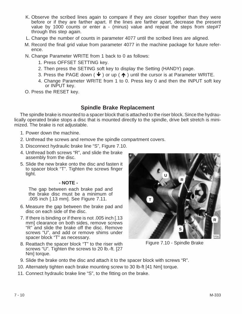
K. Observe the scribed lines again to compare if they are closer together than they werebefore or if they are farther apart. If the lines are farther apart, decrease the presentvalue by 1000 counts or enter a - (minus) value and repeat the steps from step#7through this step again.
L. Change the number of counts in parameter 4077 until the scribed lines are aligned.M. Record the final grid value from parameter 4077 in the machine package for future refer-
ence.N. Change Parameter WRITE from 1 back to 0 as follows:
1. Press OFFSET SETTING key.2. Then press the SETING soft key to display the Setting (HANDY) page.3. Press the PAGE down ( � ) or up ( � ) until the cursor is at Parameter WRITE.4. Change Parameter WRITE from 1 to 0. Press key 0 and then the INPUT soft key
or INPUT key.O. Press the RESET key.
Spindle Brake ReplacementThe spindle brake is mounted to a spacer block that is attached to the riser block. Since the hydrau-
lically operated brake stops a disc that is mounted directly to the spindle, drive belt stretch is mini-mized. The brake is not adjustable.
1. Power down the machine.2. Unthread the screws and remove the spindle compartment covers.3. Disconnect hydraulic brake line “S”, Figure 7.10.4. Unthread both screws “R”, and slide the brake
assembly from the disc.5. Slide the new brake onto the disc and fasten it
to spacer block “T”. Tighten the screws fingertight.
- NOTE -The gap between each brake pad andthe brake disc must be a minimum of.005 inch [.13 mm]. See Figure 7.11.
6. Measure the gap between the brake pad anddisc on each side of the disc.
7. If there is binding or if there is not .005 inch [.13mm] clearance on both sides, remove screws“R” and slide the brake off the disc. Removescrews “U”, and add or remove shims underspacer block “T” as necessary.
8. Reattach the spacer block “T” to the riser withscrews “U”. Tighten the screws to 20 lb.-ft. [27Nm] torque.
9. Slide the brake onto the disc and attach it to the spacer block with screws “R”.10. Alternately tighten each brake mounting screw to 30 lb-ft [41 Nm] torque.11. Connect hydraulic brake line “S”, to the fitting on the brake.
7 - 10 M-333
Figure 7.10 - Spindle Brake
U
T
R
S
R
TP58.

- NOTE -The brake can be “bled” because ofthe hydraulic pressure in the brakeline.
12. Power up the machine and bleed the line andbrake as follows:A. Loosen, but do not remove, the
“grease-fitting” nipples on each side of thebrake.
B. Tighten the lower nipples and then the up-per nipples as air escapes and the hy-draulic fluid flow becomes steady.
C. Power down the machine if the nipple leaks after it has been tightened. Remove, clean,and re-install the nipple.
D. Power up the machine and bleed the brake again.13. Test the brake as follows:
A. Press the JOG [4] pushbutton; then, press the Spindle JOG [26] pushbutton.B. Watch the gap between the brake pad and brake disc as the spindle slowly turns.C. Press the Spindle FREE [25] pushbutton to have the brake pads disengage the disc.
Press it again to engage the brake.14. Align the coolant catcher on the spindle and mount it to the top of the spindle compartment.
Tighten the screws and make certain that the interlock switch cable is clear of any moving parts.15. Attach the coolant catcher drain hose and install the coolant catcher cover.16. Mount spindle drive compartment covers and tighten the screws.
Headstock AlignmentHeadstock “V”, Figure 7.12, is secured to the machine bed by six screws “Y”. An offset dowel pin
under the headstock allows the headstock to pivot when screws “Y” are loosened and jack screw “X” isturned in adjustment block “W”.
To align the headstock:
1. Install an 8.00 inch test arbor in the spindle and mount an indicator on the turret as shown in Fig-ure 7.12.
2. Remove the spindle compartment covers Figure 7.3, motor compartment cover “B”, and discon-nect the coolant hose from the coolant catcher drain.Remove two nuts to unfasten the interlock switch. Then, remove three screws and slide theinterlock switch and cable through the back of the coolant catcher.
3. If the machine is a CONQUEST® T51/T65 standard machine, continue with the procedure tocheck runout on the next page. If the machine is a CONQUEST T51SP Super-Precision® ma-chine, remove the LVDT unit as described on page 7-15; then, continue with the procedure tocheck runout.
(continued on the next page)
M-333 7 - 11
Figure 7.11 - Spindle Brake Assembly
Brake Disc
Shim
Riser BlockSpacerBlock
Minimum .005"[.13 mm]Minimum
.005" [.13 mm]
TIA1765
BrakeBrake

To check headstock runout (Refer to Figure 7.12:
- NOTE -The indicator must be in the same position on the test arbor as the tool tip wouldbe on a workpiece.
5. Position the turret so that the indicator reads the runout at the outer end of the arbor.6. Zero the indicator. Rotate the spindle to check runout. The runout should be no more than .0007
inch [.018 mm].
To check headstock perpendicularity (Refer to Figures 7.12 and 7.13):
7. Mark a point on the arbor half way between the high and low indicator runout readings. (Split thedifference of the high and low readings.)
For example: if +0.00023 inch [0.0058mm] is the high reading and -0.00001 inch[-0.00025mm] is the low reading, +0.00012 inch [.0030mm] would be half way be-tween the two readings.
8. Reset the indicator to zero (0) at this point.9. Move the indicator along the Z axis toward the spindle.
- NOTES -On the CONQUEST® T51/T65 standard machines, the reading at the headstockend can be from 0.0 to .0008 inch [0.0 to .020 mm] in 8 inches [203.2 mm] with thelow reading at the outer end. On the CONQUEST T51SP machine, the reading atthe headstock can be from 0.0 to .0007 inch [0.0 to .018 mm] in 8 inches [203.2mm] with the low reading at the outer end.
There is no field adjustment for perpendicularity. If the indicator reading is notwithin specification, contact the Hardinge Inc. service department.
7 - 12 M-333
Figure 7.12 - Headstock Alignment
TI2607.
Dial IndicatorTest ArborV
YX W
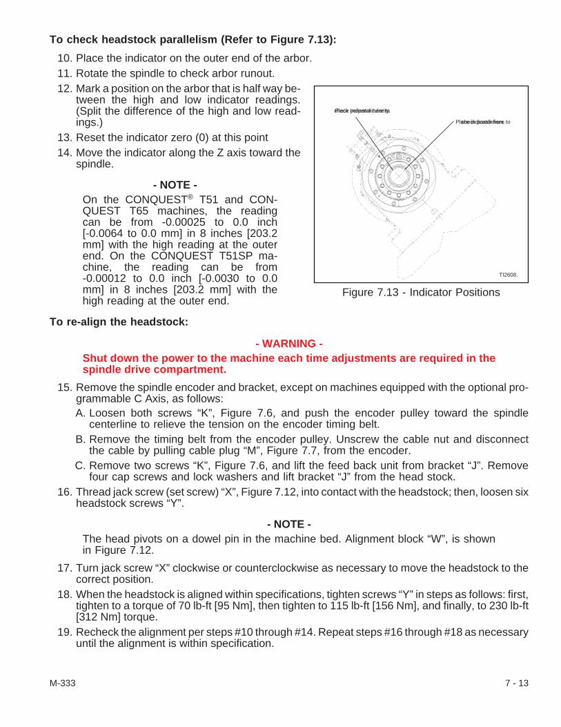
To check headstock parallelism (Refer to Figure 7.13):
10. Place the indicator on the outer end of the arbor.11. Rotate the spindle to check arbor runout.12. Mark a position on the arbor that is half way be-
tween the high and low indicator readings.(Split the difference of the high and low read-ings.)
13. Reset the indicator zero (0) at this point14. Move the indicator along the Z axis toward the
spindle.
- NOTE -On the CONQUEST® T51 and CON-QUEST T65 machines, the readingcan be from -0.00025 to 0.0 inch[-0.0064 to 0.0 mm] in 8 inches [203.2mm] with the high reading at the outerend. On the CONQUEST T51SP ma-chine, the reading can be from-0.00012 to 0.0 inch [-0.0030 to 0.0mm] in 8 inches [203.2 mm] with thehigh reading at the outer end.
To re-align the headstock:
- WARNING -Shut down the power to the machine each time adjustments are required in thespindle drive compartment.
15. Remove the spindle encoder and bracket, except on machines equipped with the optional pro-grammable C Axis, as follows:A. Loosen both screws “K”, Figure 7.6, and push the encoder pulley toward the spindle
centerline to relieve the tension on the encoder timing belt.B. Remove the timing belt from the encoder pulley. Unscrew the cable nut and disconnect
the cable by pulling cable plug “M”, Figure 7.7, from the encoder.C. Remove two screws “K”, Figure 7.6, and lift the feed back unit from bracket “J”. Remove
four cap screws and lock washers and lift bracket “J” from the head stock.16. Thread jack screw (set screw) “X”, Figure 7.12, into contact with the headstock; then, loosen six
headstock screws “Y”.
- NOTE -The head pivots on a dowel pin in the machine bed. Alignment block “W”, is shownin Figure 7.12.
17. Turn jack screw “X” clockwise or counterclockwise as necessary to move the headstock to thecorrect position.
18. When the headstock is aligned within specifications, tighten screws “Y” in steps as follows: first,tighten to a torque of 70 lb-ft [95 Nm], then tighten to 115 lb-ft [156 Nm], and finally, to 230 lb-ft[312 Nm] torque.
19. Recheck the alignment per steps #10 through #14. Repeat steps #16 through #18 as necessaryuntil the alignment is within specification.
M-333 7 - 13
Figure 7.13 - Indicator Positions
Place indicator here tocheck perpendicularity.
Place indicator here tocheck parallelism.
TI2608.

Unthread jack screw (set screw) “X”, Figure 7.12, from contact with the headstock until it isflush with alignment bracket “W”.
20. If used, re-attach the spindle encoder and adjust the encoder belt tension as described in steps athrough d below. If the machine is equipped with the 2-1/2 degree spindle orient option, the 0°position must be reset. See “To set 0° position” on page -21.A. Attach bracket “J”, Figure 7.6, to the headstock with four cap screws and lock washers.
Tighten the cap screws to a torque of 25 lb-ft [34 Nm]B. Install the feed back unit on bracket “J”, with two screws “K”.
- NOTE -Belt tension should be .15 inches [4 mm] of deflection when a force of 1.6 to 1.8pounds [7 to 8 N] is applied at a point midway between the two pulleys.
The Gates Sonic belt tension data is mass 0.39gf/Cm, width 10.0 mm, span 240.0mm, and tension 89-102 N.
C. Place the timing belt over the pulley and adjust the belt tension. Tighten screws “K”, Fig-ure 7.6, to a torque of 50 lb.-ft. [68 Nm].
D. Connect cable plug “M”, Figure 7.7, to the encoder and tighten the cable nut.21. If the machine is a CONQUEST® T51/T65 standard machine, go to step #18. If the machine is a
CONQUEST T51SP Super-Precision® machine, install and adjust the LVDT unit as describedon page 7-16 .
22. Install the spindle drive compartment covers.Feed the interlock switch through the back of the coolant catcher and attach it to the cool-ant catcher with its nuts; install the coolant catcher cover and attach the coolant catcherdrain hose.
23. Test the machine at various spindle speeds; make adjustments as necessary.24. When satisfied with the spindle drive belt tension, tighten the spindle motor cover screws.
7 - 14 M-333
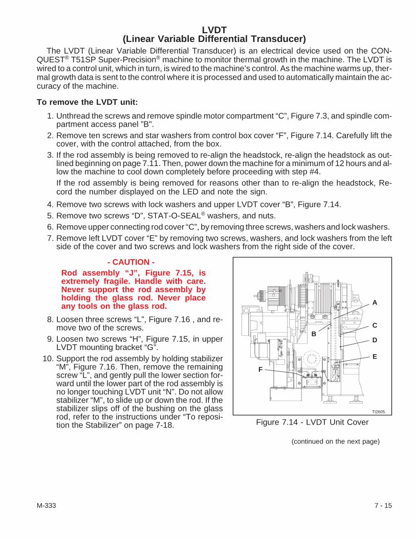
LVDT(Linear Variable Differential Transducer)
The LVDT (Linear Variable Differential Transducer) is an electrical device used on the CON-QUEST® T51SP Super-Precision® machine to monitor thermal growth in the machine. The LVDT iswired to a control unit, which in turn, is wired to the machine’s control. As the machine warms up, ther-mal growth data is sent to the control where it is processed and used to automatically maintain the ac-curacy of the machine.
To remove the LVDT unit:
1. Unthread the screws and remove spindle motor compartment “C”, Figure 7.3, and spindle com-partment access panel ”B".
2. Remove ten screws and star washers from control box cover “F”, Figure 7.14. Carefully lift thecover, with the control attached, from the box.
3. If the rod assembly is being removed to re-align the headstock, re-align the headstock as out-lined beginning on page 7.11. Then, power down the machine for a minimum of 12 hours and al-low the machine to cool down completely before proceeding with step #4.If the rod assembly is being removed for reasons other than to re-align the headstock, Re-cord the number displayed on the LED and note the sign.
4. Remove two screws with lock washers and upper LVDT cover “B”, Figure 7.14.5. Remove two screws “D”, STAT-O-SEAL® washers, and nuts.6. Remove upper connecting rod cover “C”, by removing three screws, washers and lock washers.7. Remove left LVDT cover “E” by removing two screws, washers, and lock washers from the left
side of the cover and two screws and lock washers from the right side of the cover.
- CAUTION -Rod assembly “J”, Figure 7.15, isextremely fragile. Handle with care.Never support the rod assembly byholding the glass rod. Never placeany tools on the glass rod.
8. Loosen three screws “L”, Figure 7.16 , and re-move two of the screws.
9. Loosen two screws “H”, Figure 7.15, in upperLVDT mounting bracket “G”.
10. Support the rod assembly by holding stabilizer“M”, Figure 7.16. Then, remove the remainingscrew “L”, and gently pull the lower section for-ward until the lower part of the rod assembly isno longer touching LVDT unit “N”. Do not allowstabilizer “M”, to slide up or down the rod. If thestabilizer slips off of the bushing on the glassrod, refer to the instructions under “To reposi-tion the Stabilizer” on page 7-18.
(continued on the next page)
M-333 7 - 15
Figure 7.14 - LVDT Unit CoverTI2605.
F
A
C
D
E
B

11. Continue to support the rod assembly and remove screws “H”, Figure 7.15, from upper LVDTmounting bracket “I”.
12. Carefully remove the LVDT rod assembly.
To install the LVDT unit:
- CAUTION -Rod assembly “J”, Figure 7.15, is extremely fragile. Handle with care. Never sup-port the rod assembly by holding the glass rod. Never place any tools on theglass rod.
13. Carefully place the rod assembly into the machine and install two screws “H”, and lock washersin upper LVDT mounting bracket “G”.
14. Depress the plunger on LVDT “N”, 7.16, and slide the lower portion of the rod assembly over theLVDT.
15. Release the plunger and install screws “L”, washers, and lock washers. Tighten the screws fin-ger tight.
16. Tighten screws “H”, Figure 7.15, to a torque of 25 lb.-ft. [33.9 Nm].17. Tighten screws “L”, Figure 7.16, to a torque of 100 lb.-in. [11.3 Nm].
To adjust the LVDT:
18. If the rod was removed for reasons other than to re-align the headstock, proceed with step #20. Ifthe rod was removed to realign the headstock after a crash, go to step #21.
- CAUTION -The rod assembly is extremely fragile. Handle with care. Never support the rodassembly by holding the glass rod. Never place any tools on the glass rod.
7 - 16 M-333
Figure 7.15 - LVDT Unit
GH
I
J
TI2603.
Figure 7.16 - LVDT Unit Lower Portion
N
M
LK
P
O
TI2604.
19. Check the LED readout on the LVDT control. If the reading is within ±25 counts of the value re-corded in step #3, no further adjustment is required; go to step #24. If the reading is not within±25 counts of the value recorded in step #3, place a hex pin wrench in screw “G”, Figure 7.15, atthe top of the rod assembly, and gently turn the rod assembly in the counterclockwise directionuntil the reading is within ±25 counts; go to step #24. If the adjustment does not bring the countwithin the acceptable range, go to step #23.
20. Turn the main disconnect switch to ON and press the CONTROL ON pushbutton after the ma-chine has been turned off for a minimum of 12 hours. Wait for at least 15 minutes before pro-ceeding to step #22.
21. Check the LED readout on the LVDT control. The reading should be from 0 to -50 counts. If thereading is within this range, no adjustment is necessary; go to step #24. If the reading is notwithin this range, go to step #23.
22. Adjust LVDT unit “N”, Figure 7.16, as follows:A. Determine in which direction the LVDT must be moved to bring the reading within range.
For example; if the reading is -75, the LVDT unit must be moved down or awayfrom the rod assembly until the reading falls within the specified range. If the read-ing is +100, the LVDT unit must be moved up or toward the rod assembly until thereading falls within the specified range.
- NOTE -When making the adjustments to the LVDT unit, the nuts should be loosened andtightened in small increments, for example, 1/20 of a turn or less.
B. To adjust LVDT unit “N”, Figure 7.16, down, loosen the upper nut on the LVDT unit andtighten the lower nut. To adjust the LVDT unit up, loosen the lower nut and tighten theupper nut.
C. Check the reading. If it is within the specified range go to step #24. If the reading is notwithin the specified range, repeat steps A through C.
23. Carefully place the control unit back in control box and attach control box cover “F”, Figure 7.14,screws and star washers.
24. Attach left LVDT cover “E”, using two screws, washers, and lock washers.25. Install two screws and lockwashers.26. Attach upper connecting rod cover “C”, using three screws, washers, and lockwashers.27. Install two screws, STAT-O-SEAL® washers, and nuts “D”.28. Attach upper LVDT cover “B”, using two screws and lock washers.29. Install the spindle drive compartment covers.
Feed the interlock switch through the back of the coolant catcher and attach it to the cool-ant catcher with its nuts; install the coolant catcher cover and attach the coolant catcherdrain hose.
30. Test the machine at various spindle speeds; make adjustments as necessary.When satisfied with the spindle drive belt tension, tighten the spindle motor cover screws.
M-333 7 - 17
To reposition the Stabilizer:
- CAUTION -The rod assembly is extremely fragile. Handle with care. Never support the rodassembly by holding the glass rod. Never place any tools on the glass rod.
1. Remove the rod assembly from the machine and take it to a work bench for further disassembly.Secure stabilizer “M”, Figure 7.16, in a vise and remove three screws “P”.
2. Remove spring “O”, and plunger “K”.3. Remove the rod from the stabilizer and clean all Loctite® 242 Threadlocker residue from the
holes and from the threads on screws “P”.4. Place the stabilizer back on the rod so that the threaded holes in the stabilizer are aligned with
the bushing.5. Place plunger “K”, and spring “O”, in the hole. Apply a drop of Loctite 242 Threadlocker to the
threads of screw “P” and install it in the hole. Repeat this for the other two holes.6. Install the rod assembly on the machine.
2-1/2 Degree Spindle Orient OptionUnless the machine has the programmable C-Axis option, the 2-1/2 degree spindle orient option is
standard equipment on CONQUEST® T51/T65 series machines equipped with the live tooling option.One degree spindle orient is included with the 2-1/2 degree spindle orient option. The spindle can beoriented in one degree increments from 0 to 359 degrees. With one degree spindle orient, the spindlebrake holds the spindle in position.
To remove the 2-1/2 degree spindle orient assembly:
1. Power down the machine.Unthread the screws and remove spindle motor compartment “C”, Figure 7.3, and spindlecompartment access panel ”B".
2. If the spindle orient assembly is to be removed completely from the machine, continue with step#4. If the assembly will not be removed completely, go to step #6.
3. Tag the hoses for reconnection and disconnect them from the unit.4. Remove nut “Q”, Figure 7.17, from each switch and pull the switch out of the bracket.5. Remove two pullout dowels “U”.6. Remove four cap screws “J”, and separate assembly “S”, from the headstock. Do not lose the
shims, if any, that are located between the assembly and the headstock.
To disassemble and re-assemble 2-1/2 degree spindle orient assembly(Refer to Figure 7.18 ):
1. Remove the assembly from the machine as described in the previous section.2. Remove screws, washers and lockwashers “S”, Figure 7.18, and remove switch
brackets “R”.
- NOTE -In steps #3 through #26 work on one cavity at a time.
3. Remove four screws “P”, and lift off cap assembly “F”.4. Loosen nut “T”, Figure 7.18, and unthread set screws “U”, out of the assembly.5. Pull tapered shaft “G”, out of the Oilite bearing and cylinder liner.
7 - 18 M-333

6. Remove cylinder liner “D”.7. If necessary, remove oilite bearing “A”, and re-
taining ring “N”.8. Remove nut “I”, and piston “E”, from tapered
shaft “G”, if necessary.9. Remove fittings “O”, from housing “Q”, if re-
quired.10. Remove all exposed O-rings and Quad rings.11. Clean all parts thoroughly and stone to remove
any nicks, burrs, or high spots.
(continued on the next page)
M-333 7 - 19
Figure 7.17 - 2-1/2 DegreeSpindle Orient Assembly
TP343.
QR S
T
VU
Figure 7.18 - 2-1/2 Degree Spindle Orient Assembly
AB
CD
EF
GHI
JKLM
N
O
Q
PRST
U
TI2574

12. Remove all traces of pipe sealant and threadlocker from all threaded parts. Use compressed airto blow any debris from fittings and openings.
13. Apply Loctite® 92-41 pipe sealant to the first two threads of the fittings and install them in housing“Q”, Figure 7.18.
14. If they were removed, install retainer “N”, and Oilite® bearing “A”. The hole in the side of the bear-ing must be aligned with the threaded hole in the housing.
15. Thread screw “U”, part way into the housing. Do not allow the dog point to extend past the bear-ing.
16. If the original cylinder liner is being installed, go to step #20. If a new cylinder liner is being in-stalled, continue with step #17.
17. Place cylinder liner “D”, into the housing without any O-rings or Quad rings.18. Measure dimensions A and B as shown in Fig-
ure 7.19.19. Remove cylinder liner “D”, Figure 7.18, and
face the surface indicated to provide the gapshown when the liner and end cap are assem-bled in the housing.
- NOTE -A light coat of Molykote® 55M lubricantmust be applied to all O-rings andQuad rings before re-assembly.
20. Install new O-rings “C”, “H”, “J”, “L”, and “M”,and new Quad rings “B”, and “K”.
21. Slide cylinder liner “D”, into the housing.22. If it was removed, slide piston “E”, onto tapered
shaft “G”. Apply a drop of Loctite 242threadlocker to the threads on the shaft and in-stall nut “I”. Tighten the nut to a torque of 200lb.-in. [23 Nm].
23. Apply a light coat of Molylube® Anti-Seize lubri-cant to section of tapered shaft “G”, that passesthrough oilite bearing “A”.
24. Align the groove in shaft “G”, with the dog point on the set screw and slide the shaft and pistonassembly into the cylinder liner and through oilite bearing “A”.
25. Thread screw “U”, in until it bottoms against the groove in shaft “G”; then, back the screw off halfa turn.
26. Install cap “F”, using four screws “P”. Tighten the screws to a torque of 60 lb-in. [7 Nm].27. Push the shaft in and out to check for binding.
Repeat the steps for the other cylinder.
28. Attach switch brackets “R”, using screws, washers, and lock washers “S”.
7 - 20 M-333
Figure 7.19 - Cylinder Liner and End Cap
TI2618.
Dim. A
Dim. B
Face this surface so thatDim. A is .001 to .003 in. [.025 - .076 mm]greater than Dim. B
Gap is .001 - .003 in.[.025 - .076 mm]

To install 2-1/2 degree spindle orient assembly:
1. Be sure the shims, if used, are in position and place 2-1/2 degree spindle orient assemblyagainst the headstock. Install four screws “J”, Figure 7.17, so that they are just snug.
2. Install push dowels “U”.3. Tighten screws “V”, to a torque of 25 lb.-ft. [34 Nm].4. Re-attach the switch assemblies and adjust to provide 0.015 to 0.020 inch [0.38 to 0.50 mm]
clearance between the switch and the tapered shaft with the shafts not engaged. Tighten thenuts on the switch to secure the setting.
5. Adjust the switch assemblies so that the switches will activate when the tip of the shaft is 0.060inch [1.52 mm] from the teeth as follows:A. Press the CONTROL ON pushbutton. Press the E-Stop [74] pushbutton and make cer-
tain that it remains down.B. Press the OFFSET SETTING key to display the Setting (HANDY) page.C. Press the SETTING soft key. Then, key in 3076 and press the INPUT key. The cursor
will be flashing at DIAGNOSTIC 3076.D. Observe Diagnostic X3076 bits 0 and 1 while moving the shaft toward the teeth.
- NOTE -The number to the left of the decimal point is the diagnostic word address. Thenumber to the right of the decimal point identifies a specific bit of that word. Bit 0 isthe bit for the top limit switch (24PRS) and bit 1 is the bit for the bottom limit switch(25PRS). The N’s represent bits that are not associated with this procedure.
7 6 5 4 3 2 1 0 (Bit Numbers)
Address 3076 N N N N N N 0 0 (Bit Settings)
E. Loosen screws “P”, Figure 7.18, on each side of the switch bracket to allow the upperswitch assembly to just slide toward and away from the spindle.
F. Place a .060 inch [1.52 mm] shim against the teeth and move the tip of the upper shafttoward the spindle until the tip of the shaft is against the shim.
G. Move the switch bracket toward the spindle until bit 0 changes from 0 to 1. Tightenscrews “P” to secure the setting.
H. Repeat steps 5.C through 5.F for the lower shaft and switch.6. Reconnect all air hoses to the assembly except hose no. 3 to the lower pin. Leave this hose dis-
connected and plugged off until the 0° position has been set.7. Power up the machine and set the 0° spindle orient position. Connect hose no. 3 to the lower pin.8. Install the spindle drive compartment covers.
Feed the interlock switch through the back of the coolant catcher and attach it to the cool-ant catcher with its nuts; install the coolant catcher cover and attach the coolant catcherdrain hose.
M-333 7 - 21

Programmable C-Axis OptionThe programmable C-Axis option makes it possible to perform milling and turning operations on the
same machine. Polar Coordinate Interpolation is used for face milling operations and Cylindrical Inter-polation is used for contoured milling on the outside diameter of the workpiece.
- CAUTION -Do not place any type of magnetic device near encoder “M”, Figure 7.21.
To remove the C-Axis assembly:
1. Power down the machine.2. Remove the spindle compartment covers Figure 7.3, motor compartment cover “B”, and discon-
nect the coolant hose from the coolant catcher drain.Remove two nuts to unfasten the interlock switch. Then, remove three screws and slide theinterlock switch and cable through the back of the coolant catcher.
- CAUTION -The C Axis assembly contains delicate parts that may be easily damaged. For thisreason, it is recommended that service operations involving this assembly beperformed by a HARDINGE Service Representative. However, if you elect to ser-vice this assembly, be sure to follow all procedures exactly as they are written.
3. Remove the spindle tooling if installed. Pull the collet closer draw tube out of the spindle approxi-mately 16 inches [406 mm], place an air line in the outer end of the draw tube to blow chips andcoolant from the spindle. Then, pull the draw tube completely out of the spindle.
- WARNING -The collet closer weighs approxi-mately 80 pounds [36 kg]. Be pre-pared to accept this weight.
- CAUTION -Do not set the collet closer on end.Setting the closer on end may causedamage to the closer.
5. Support the collet closer assembly and removeeight screws and lock washers. Carefully sepa-rate the collet closer assembly from the spindle.
6. Remove eight screws “A”, Figure 7.20, andbrake disc “B”.
7. Remove clamp screws and washers “D” andseparate the pick-up lead cable from cover “C”.
8. Remove two screws “E” from each side of thespindle and carefully pull cover “C” off of thespindle.
7 - 22 M-333
Figure 7.20 - C Axis Assembly
TP345
Db
a
A
BF G
H
E
C
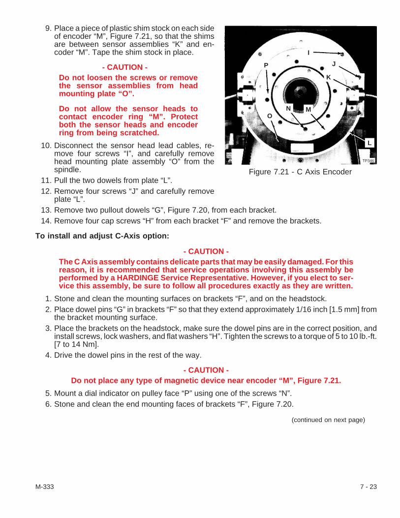
9. Place a piece of plastic shim stock on each sideof encoder “M”, Figure 7.21, so that the shimsare between sensor assemblies “K” and en-coder “M”. Tape the shim stock in place.
- CAUTION -Do not loosen the screws or removethe sensor assemblies from headmounting plate “O”.
Do not allow the sensor heads tocontact encoder ring “M”. Protectboth the sensor heads and encoderring from being scratched.
10. Disconnect the sensor head lead cables, re-move four screws “I”, and carefully removehead mounting plate assembly “O” from thespindle.
11. Pull the two dowels from plate “L”.12. Remove four screws “J” and carefully remove
plate “L”.13. Remove two pullout dowels “G”, Figure 7.20, from each bracket.14. Remove four cap screws “H” from each bracket “F” and remove the brackets.
To install and adjust C-Axis option:
- CAUTION -The C Axis assembly contains delicate parts that may be easily damaged. For thisreason, it is recommended that service operations involving this assembly beperformed by a HARDINGE Service Representative. However, if you elect to ser-vice this assembly, be sure to follow all procedures exactly as they are written.
1. Stone and clean the mounting surfaces on brackets “F”, and on the headstock.2. Place dowel pins “G” in brackets “F” so that they extend approximately 1/16 inch [1.5 mm] from
the bracket mounting surface.3. Place the brackets on the headstock, make sure the dowel pins are in the correct position, and
install screws, lock washers, and flat washers “H”. Tighten the screws to a torque of 5 to 10 lb.-ft.[7 to 14 Nm].
4. Drive the dowel pins in the rest of the way.
- CAUTION -Do not place any type of magnetic device near encoder “M”, Figure 7.21.
5. Mount a dial indicator on pulley face “P” using one of the screws “N”.6. Stone and clean the end mounting faces of brackets “F”, Figure 7.20.
(continued on next page)
M-333 7 - 23
Figure 7.21 - C Axis Encoder
TP346
O
P
I
J
K
L
N M

7. Rotate the spindle until the indicator contacts one of the bracket faces. Indicate both faces. If ad-justment is necessary, use a piece of brass stock to tap on the sides of the brackets to bring theminto alignment.
- NOTE -Mounting faces should be aligned to within 0.0004 inch [0.010 mm].
8. Tighten screws “H” to a torque of 25 lb.-ft. [34 Nm] and recheck the alignment.9. Remove the dial indicator and stone and clean the mounting surfaces of plate “L”, Figure 7.21.
10. Install dowel pins in plate “L” so that they extend approximately 1/16 inch [1.5 mm] from theplate.
11. Align the dowels with the holes in the mounting brackets, and carefully install plate “L” on thespindle. Then, install four screws “J” and tighten the screws to a torque of 40 lb.-in. [5 Nm]
12. Drive the dowels in until they are below the surface of the mounting plate.
- CAUTION -Do not place any type of magnetic device near encoder “M”, Figure 7.21.
13. Mount a dial indicator and indicate the small O.D. and face of plate “L” in the area where the sen-sors will be placed. If necessary tap on the large O.D. of the plate to bring it into alignment.
- NOTE -The plate should be within 0.0008 in [0.020 mm] on the face and 0.0004 in [0.010mm] on the small O.D.
14. Remove screws “J” one at a time and apply a drop of Loctite® 242 Threadlocker to the threads.Re-install the screws and tighten to 120 lb.-in. [14 Nm] of torque.
15. Recheck the indicator readings.16. Be sure the shim stock is in place from step #9 of the Removal Procedure and install sensor
head mounting plate “O” on the spindle. Tighten screws “I” to 70 lb.-in. [8 Nm] of torque.17. Remove the protective pieces of plastic shim from around the encoder.
- CAUTION -Do not remove or adjust sensors “K”. Clearance gap should be from .0035 to.0047 inch [.089 to .119 mm]. The difference between the two sides should be lessthan .0008 inch [.020 mm].
18. Use a plastic shim only and measure the clearance between sensors “K” and encoder “M”.19. If the sensors units have been installed or if the sensor units have been disturbed, continue with
step #20. If the sensor assembly was removed and installed without moving the sensors, go tostep #35.
7 - 24 M-333

Sensor setup and adjustment:
- CAUTION -The ground for the oscilloscopemust be isolated at the power cord.
20. Isolate the ground for the oscilloscope at thepower cord. Set the oscilloscope for an X - Yplot and zero both channels. Make certain thatboth channels are set at the same voltage level,DC volts (.2 v/div.).
- WARNING -The components in the power caseare electrical hazards. They can alsobe damaged when contact is madewith them while the machine is pow-ered up. Be extremely careful whenworking in the power case.
21. Connect the probes at C-axis detection board“A”, Figure 7.22, as follows:
Channel 1 probe to spindle servo unit“VA1", Figure 7.23.Channel 2 probe to spindle servo unit“VB1".COMMON to “VRM”.
22. Disconnect the unit cable labeled “CN0" fromits pre-amplification box cable.
23. Remove the screws, washers and lockwashersthat secure pre-amplification box “Q”, Figure7.24, to the machine. Then, unthread thescrews and remove the cover.
24. Set the potentiometers in the pre-amplificationbox by turning them all the way counterclock-wise and then clockwise to the second indicatorline.
25. Power-up the machine.26. Set the spindle to run at 100 rpm as follows:
A. Press the Machine Mode MDI pushbutton.B. Press the PRGRM key.C. Press the RESET key.D. Key in M 0 3 and press the INPUT key.E. Key in S 1 0 0 and press the INPUT key.F. Press the CYCLE START [72] pushbutton.
M-333 7 - 25
Figure 7.22 - C-Axis BoardTP347
A
Figure 7.23 - C-Axis Detection Board
VRM
TI2648
VB2VA2VB1VA1VB3VA3
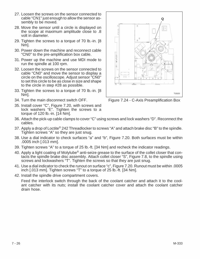
27. Loosen the screws on the sensor connected tocable “CN1" just enough to allow the sensor as-sembly to be moved.
28. Move the sensor until a circle is displayed onthe scope at maximum amplitude close to .8volt in diameter.
29. Tighten the screws to a torque of 70 lb.-in. [8Nm].
30. Power down the machine and reconnect cable“CN0" to the pre-amplification box cable.
31. Power up the machine and use MDI mode torun the spindle at 100 rpm.
32. Loosen the screws on the sensor connected tocable “CN0" and move the sensor to display acircle on the oscilloscope. Adjust sensor ”CN0"to set this circle to be as close in size and shapeto the circle in step #28 as possible.
33. Tighten the screws to a torque of 70 lb.-in. [8Nm].
34. Turn the main disconnect switch OFF.35. Install cover “C”, Figure 7.20, with screws and
lock washers “E”. Tighten the screws to atorque of 120 lb.-in. [14 Nm].
36. Attach the pick-up cable clamps to cover “C” using screws and lock washers “D”. Reconnect thecables.
37. Apply a drop of Loctite® 242 Threadlocker to screws “A” and attach brake disc “B” to the spindle.Tighten screws “A” so they are just snug.
38. Use a dial indicator to check surfaces “a” and “b”, Figure 7.20. Both surfaces must be within.0005 inch [.013 mm].
39. Tighten screws “A” to a torque of 25 lb.-ft. [34 Nm] and recheck the indicator readings.40. Apply a light coating of Molylube® anti-seize grease to the surface of the collet closer that con-
tacts the spindle brake disc assembly. Attach collet closer “S”, Figure 7.8, to the spindle usingscrews and lockwashers “T”. Tighten the screws so that they are just snug.
41. Use a dial indicator to check the runout on surface “c”, Figure 7.20. Runout must be within .0005inch [.013 mm]. Tighten screws “T” to a torque of 25 lb.-ft. [34 Nm].
42. Install the spindle drive compartment covers.Feed the interlock switch through the back of the coolant catcher and attach it to the cool-ant catcher with its nuts; install the coolant catcher cover and attach the coolant catcherdrain hose.
7 - 26 M-333
Figure 7.24 - C-Axis Preamplification Box
TI2620
Q

- NOTES -
M-333 7 - 27

- NOTES -
7 - 28 M-333

CHAPTER 8 - COLLET CLOSER
IntroductionThe CONQUEST® T51 and CONQUEST T65 series lathes are equipped with a 1.18 inch [30 mm]
stroke, hydraulically actuated collet closer. If repairs to the collet closer are required, the ENTIRE AS-SEMBLY must be removed and returned to the factory.
Free SpindleA “Free Spindle” condition allows the spindle to be easily turned by hand.
To obtain a “Free Spindle”:
1. If necessary, power up the machine. The machine must be ON and the spindle not turning.2. Press the RESET key.3. Press machine mode JOG [4] pushbutton, Figure 8.1.4. Press spindle FREE [25] pushbutton.
- NOTE -“Free Spindle” may also be obtained if either axis mode Zero Return [69], Figure8.1, or program protect Edit [12] is active.
M-333 8 - 1
Figure 8.1 - Operator Control Panel
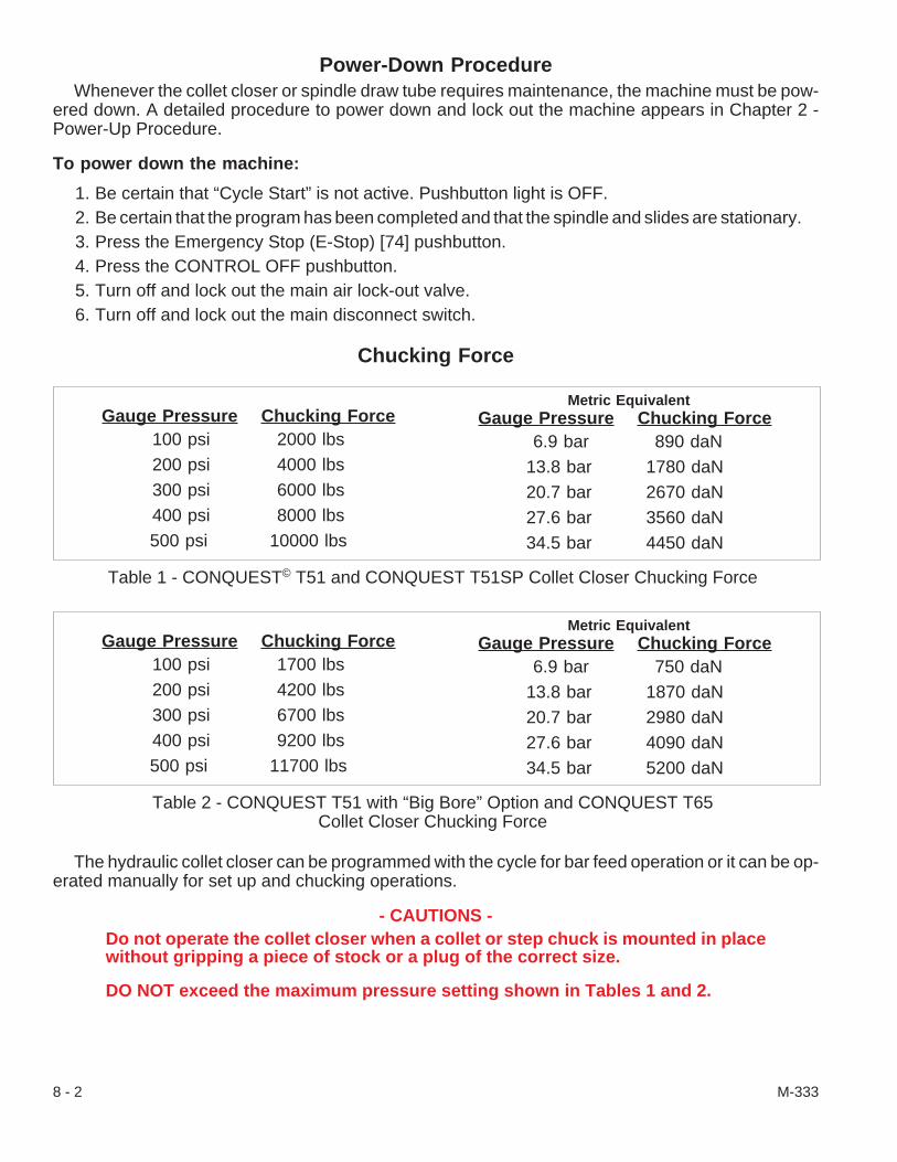
Power-Down ProcedureWhenever the collet closer or spindle draw tube requires maintenance, the machine must be pow-
ered down. A detailed procedure to power down and lock out the machine appears in Chapter 2 -Power-Up Procedure.
To power down the machine:
1. Be certain that “Cycle Start” is not active. Pushbutton light is OFF.2. Be certain that the program has been completed and that the spindle and slides are stationary.3. Press the Emergency Stop (E-Stop) [74] pushbutton.4. Press the CONTROL OFF pushbutton.5. Turn off and lock out the main air lock-out valve.6. Turn off and lock out the main disconnect switch.
Chucking Force
The hydraulic collet closer can be programmed with the cycle for bar feed operation or it can be op-erated manually for set up and chucking operations.
- CAUTIONS -Do not operate the collet closer when a collet or step chuck is mounted in placewithout gripping a piece of stock or a plug of the correct size.
DO NOT exceed the maximum pressure setting shown in Tables 1 and 2.
8 - 2 M-333
Gauge Pressure Chucking Force6.9 bar 890 daN
13.8 bar 1780 daN20.7 bar 2670 daN27.6 bar 3560 daN34.5 bar 4450 daN
Gauge Pressure Chucking Force100 psi 2000 lbs200 psi 4000 lbs300 psi 6000 lbs400 psi 8000 lbs500 psi 10000 lbs
Metric Equivalent
Table 1 - CONQUEST© T51 and CONQUEST T51SP Collet Closer Chucking Force
Gauge Pressure Chucking Force6.9 bar 750 daN
13.8 bar 1870 daN20.7 bar 2980 daN27.6 bar 4090 daN34.5 bar 5200 daN
Gauge Pressure Chucking Force100 psi 1700 lbs200 psi 4200 lbs300 psi 6700 lbs400 psi 9200 lbs500 psi 11700 lbs
Metric Equivalent
Table 2 - CONQUEST T51 with “Big Bore” Option and CONQUEST T65Collet Closer Chucking Force
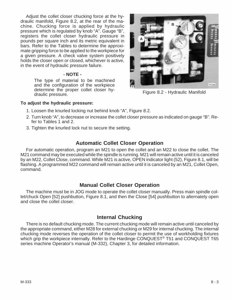
Adjust the collet closer chucking force at the hy-draulic manifold, Figure 8.2, at the rear of the ma-chine. Chucking force is applied by hydraulicpressure which is regulated by knob “A”. Gauge “B”,registers the collet closer hydraulic pressure inpounds per square inch and its metric equivalent inbars. Refer to the Tables to determine the approxi-mate gripping force to be applied to the workpiece fora given pressure. A check valve system positivelyholds the closer open or closed, whichever is active,in the event of hydraulic pressure failure.
- NOTE -The type of material to be machinedand the configuration of the workpiecedetermine the proper collet closer hy-draulic pressure.
To adjust the hydraulic pressure:
1. Loosen the knurled locking nut behind knob “A”, Figure 8.2.2. Turn knob “A”, to decrease or increase the collet closer pressure as indicated on gauge “B”. Re-
fer to Tables 1 and 2.3. Tighten the knurled lock nut to secure the setting.
Automatic Collet Closer OperationFor automatic operation, program an M21 to open the collet and an M22 to close the collet. The
M21 command may be executed while the spindle is running. M21 will remain active until it is canceledby an M22, Collet Close, command. While M21 is active, OPEN indicator light (52), Figure 8.1, will beflashing. A programmed M22 command will remain active until it is canceled by an M21, Collet Open,command.
Manual Collet Closer OperationThe machine must be in JOG mode to operate the collet closer manually. Press main spindle col-
let/chuck Open [52] pushbutton, Figure 8.1, and then the Close [54] pushbutton to alternately openand close the collet closer.
Internal ChuckingThere is no default chucking mode. The current chucking mode will remain active until canceled by
the appropriate command, either M28 for external chucking or M29 for internal chucking. The internalchucking mode reverses the operation of the collet closer to permit the use of workholding fixtureswhich grip the workpiece internally. Refer to the Hardinge CONQUEST® T51 and CONQUEST T65series machine Operator’s manual (M-332), Chapter 3, for detailed information.
M-333 8 - 3
Figure 8.2 - Hydraulic Manifold
A
B
TP348.
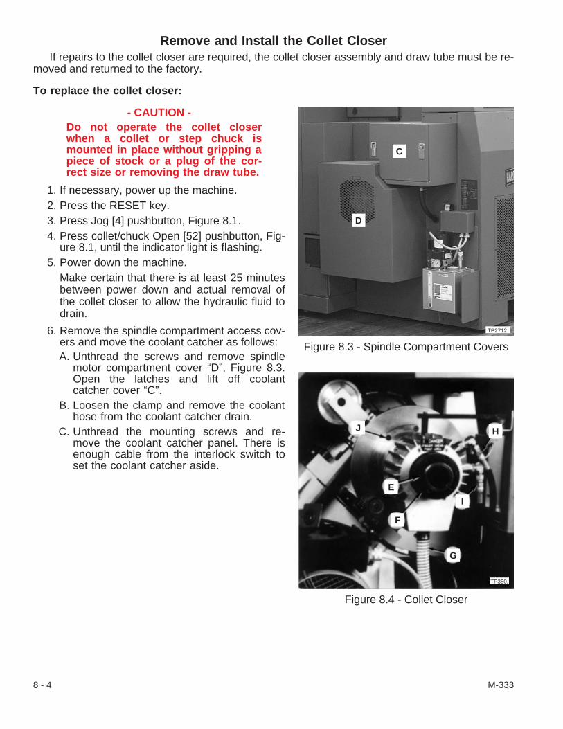
Remove and Install the Collet CloserIf repairs to the collet closer are required, the collet closer assembly and draw tube must be re-
moved and returned to the factory.
To replace the collet closer:
- CAUTION -Do not operate the collet closerwhen a collet or step chuck ismounted in place without gripping apiece of stock or a plug of the cor-rect size or removing the draw tube.
1. If necessary, power up the machine.2. Press the RESET key.3. Press Jog [4] pushbutton, Figure 8.1.4. Press collet/chuck Open [52] pushbutton, Fig-
ure 8.1, until the indicator light is flashing.5. Power down the machine.
Make certain that there is at least 25 minutesbetween power down and actual removal ofthe collet closer to allow the hydraulic fluid todrain.
6. Remove the spindle compartment access cov-ers and move the coolant catcher as follows:A. Unthread the screws and remove spindle
motor compartment cover “D”, Figure 8.3.Open the latches and lift off coolantcatcher cover “C”.
B. Loosen the clamp and remove the coolanthose from the coolant catcher drain.
C. Unthread the mounting screws and re-move the coolant catcher panel. There isenough cable from the interlock switch toset the coolant catcher aside.
8 - 4 M-333
Figure 8.3 - Spindle Compartment Covers
D
C
TP2712.
Figure 8.4 - Collet Closer
J
E
F
I
H
G
TP350.

- CAUTION -Remove the spindle draw tube before removing the collet closer. The weight ofthe collet closer could distort the draw tube if the draw tube is only partially re-moved and the collet closer is still attached.
7. Remove the spindle draw tube as follows:A. Completely loosen six screws “E”, Figure 8.4, in the adjusting nut of the draw tube.
- NOTES -The collet closer adjusting nut may be warm if the machine has been running.
Six screws “E”, must be completely unthreaded from the collet closer liner beforedraw tube “F”, can be turned.
The removal of a step chuck may require the assistance of a second person.
B. Turn draw tube “F”, counterclockwise to unthread it from the workholding device.
- WARNING -Be prepared to accept the weight of the workholding device.
C. Remove the workholding device (collet or chuck) from the spindle.D. Slide the draw tube out of the spindle approximately 16 inches [406 mm].
From the collet closer end of the draw tube, use air or a cloth to remove chips and cool-ant from the spindle. Then, fully slide the draw tube from the spindle.
E. Wipe the inside of the spindle clean with an oiled lint-free cloth.8. Remove the hoses and support bracket from the collet closer as follows:
A. Loosen the clamp and disconnect hydraulic hose “G”.B. Unthread the universal fittings and disconnect “Collet Close” hydraulic line “H”, and “Col-
let Open” hydraulic line “I”.C. Unthread the screw from the top of the support bracket and free the collet closer.
- WARNING -The collet closer assembly weighs approximately 80 pounds [36kg]. Be preparedto accept the weight of the collet closer when the last few screws are unthreaded.
9. Support the collet closer assembly, push and hold it against the spindle brake disc, and removeeight screws “J”. Carefully separate the collet closer assembly from the spindle brake disc andremove it from the spindle drive compartment.
- CAUTION -Place the collet closer on its side. Do not stand it on end.
10. Place the collet closer assembly on a protective surface on a heavy duty work bench.
M-333 8 - 5
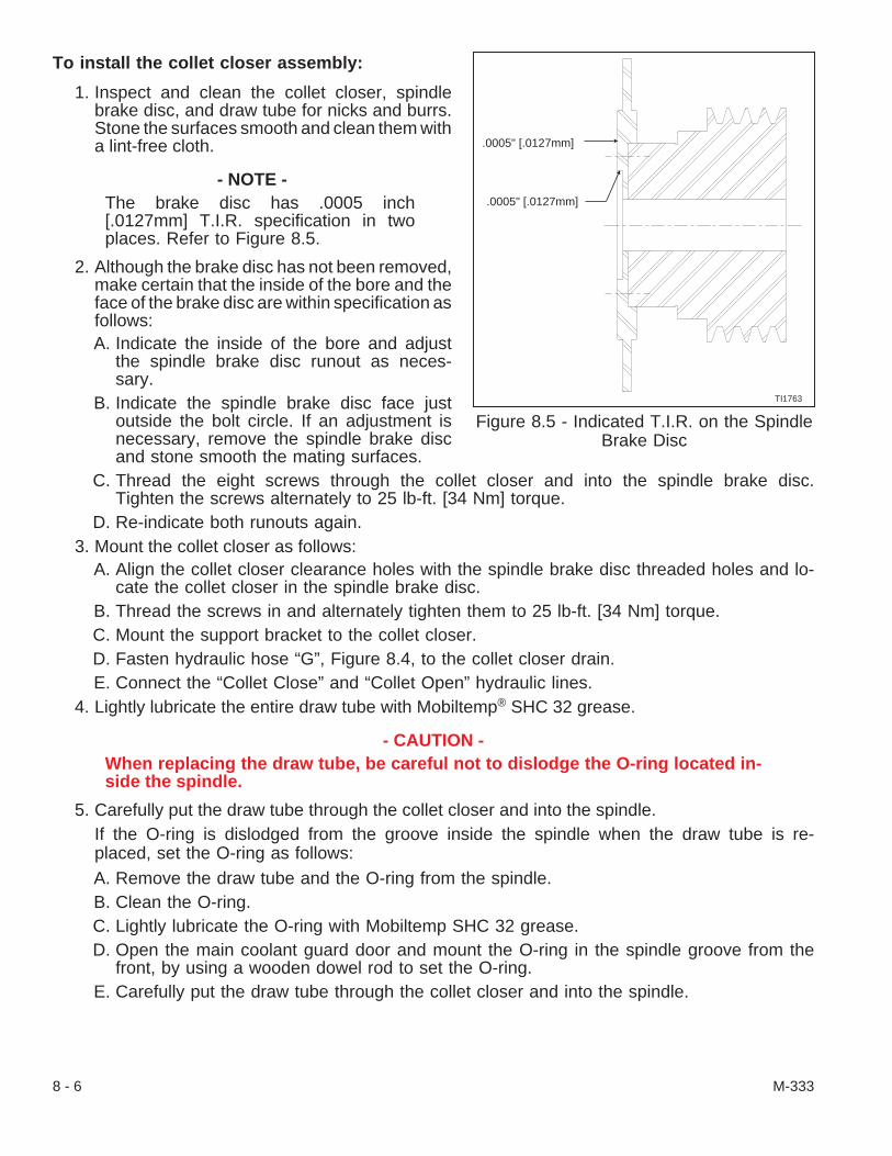
To install the collet closer assembly:
1. Inspect and clean the collet closer, spindlebrake disc, and draw tube for nicks and burrs.Stone the surfaces smooth and clean them witha lint-free cloth.
- NOTE -The brake disc has .0005 inch[.0127mm] T.I.R. specification in twoplaces. Refer to Figure 8.5.
2. Although the brake disc has not been removed,make certain that the inside of the bore and theface of the brake disc are within specification asfollows:A. Indicate the inside of the bore and adjust
the spindle brake disc runout as neces-sary.
B. Indicate the spindle brake disc face justoutside the bolt circle. If an adjustment isnecessary, remove the spindle brake discand stone smooth the mating surfaces.
C. Thread the eight screws through the collet closer and into the spindle brake disc.Tighten the screws alternately to 25 lb-ft. [34 Nm] torque.
D. Re-indicate both runouts again.3. Mount the collet closer as follows:
A. Align the collet closer clearance holes with the spindle brake disc threaded holes and lo-cate the collet closer in the spindle brake disc.
B. Thread the screws in and alternately tighten them to 25 lb-ft. [34 Nm] torque.C. Mount the support bracket to the collet closer.D. Fasten hydraulic hose “G”, Figure 8.4, to the collet closer drain.E. Connect the “Collet Close” and “Collet Open” hydraulic lines.
4. Lightly lubricate the entire draw tube with Mobiltemp® SHC 32 grease.
- CAUTION -When replacing the draw tube, be careful not to dislodge the O-ring located in-side the spindle.
5. Carefully put the draw tube through the collet closer and into the spindle.If the O-ring is dislodged from the groove inside the spindle when the draw tube is re-placed, set the O-ring as follows:A. Remove the draw tube and the O-ring from the spindle.B. Clean the O-ring.C. Lightly lubricate the O-ring with Mobiltemp SHC 32 grease.D. Open the main coolant guard door and mount the O-ring in the spindle groove from the
front, by using a wooden dowel rod to set the O-ring.E. Carefully put the draw tube through the collet closer and into the spindle.
8 - 6 M-333
Figure 8.5 - Indicated T.I.R. on the SpindleBrake Disc
TI1763
.0005" [.0127mm]
.0005" [.0127mm]
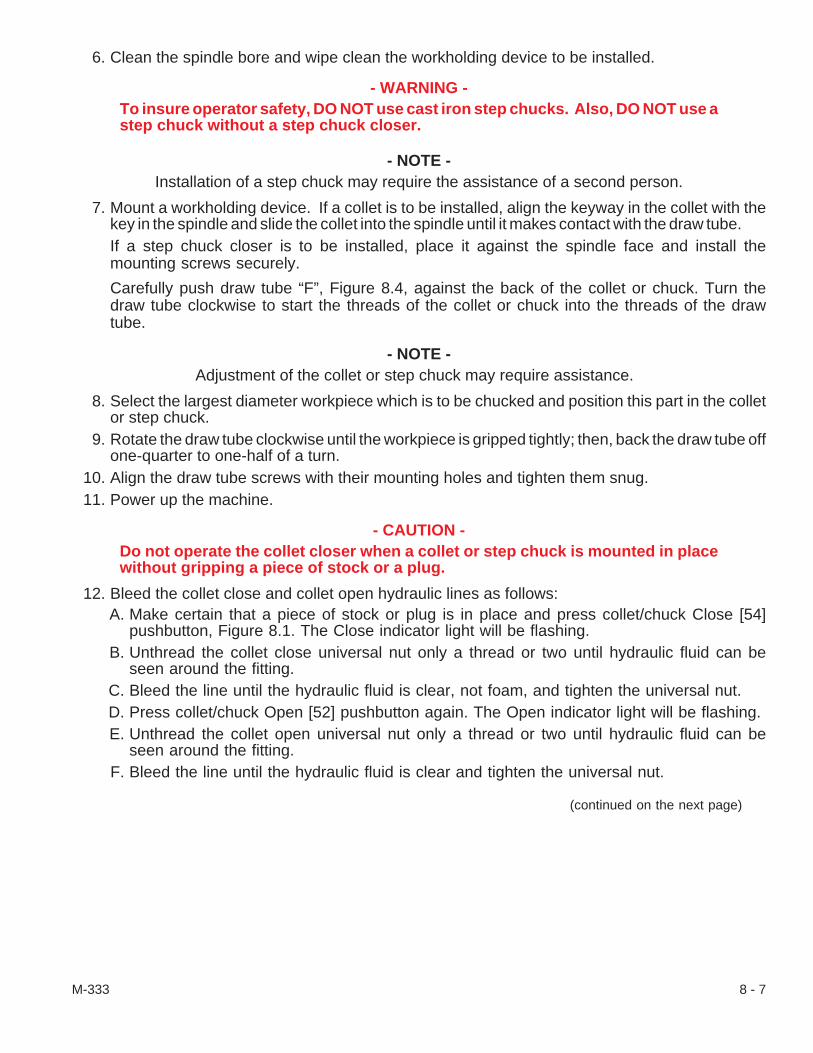
6. Clean the spindle bore and wipe clean the workholding device to be installed.
- WARNING -To insure operator safety, DO NOT use cast iron step chucks. Also, DO NOT use astep chuck without a step chuck closer.
- NOTE -Installation of a step chuck may require the assistance of a second person.
7. Mount a workholding device. If a collet is to be installed, align the keyway in the collet with thekey in the spindle and slide the collet into the spindle until it makes contact with the draw tube.If a step chuck closer is to be installed, place it against the spindle face and install themounting screws securely.
Carefully push draw tube “F”, Figure 8.4, against the back of the collet or chuck. Turn thedraw tube clockwise to start the threads of the collet or chuck into the threads of the drawtube.
- NOTE -Adjustment of the collet or step chuck may require assistance.
8. Select the largest diameter workpiece which is to be chucked and position this part in the colletor step chuck.
9. Rotate the draw tube clockwise until the workpiece is gripped tightly; then, back the draw tube offone-quarter to one-half of a turn.
10. Align the draw tube screws with their mounting holes and tighten them snug.11. Power up the machine.
- CAUTION -Do not operate the collet closer when a collet or step chuck is mounted in placewithout gripping a piece of stock or a plug.
12. Bleed the collet close and collet open hydraulic lines as follows:A. Make certain that a piece of stock or plug is in place and press collet/chuck Close [54]
pushbutton, Figure 8.1. The Close indicator light will be flashing.B. Unthread the collet close universal nut only a thread or two until hydraulic fluid can be
seen around the fitting.C. Bleed the line until the hydraulic fluid is clear, not foam, and tighten the universal nut.D. Press collet/chuck Open [52] pushbutton again. The Open indicator light will be flashing.E. Unthread the collet open universal nut only a thread or two until hydraulic fluid can be
seen around the fitting.F. Bleed the line until the hydraulic fluid is clear and tighten the universal nut.
(continued on the next page)
M-333 8 - 7

13. Press collet/chuck Close [54] pushbutton, Figure 8.1, to close the collet and check the grippingforce on the workpiece.If the gripping force is satisfactory, go to step #14.
If the gripping force is more or less than desired, adjust knob “A”, Figure 8.2, to any settingbetween 100 and 500 psi (6.9 and 34.5 bars). Refer to Table 1.
- CAUTION -If the machine will not be operated with a bar feed system, the spindle draw tubeplug, should be installed in the back of the spindle to minimize coolant and chipsfrom entering the coolant catcher compartment.
14. Power down the machine and install the spindle draw tube plug, if it was removed or if a bar feedsystem is not used.
15. Replace the spindle compartment covers as follows:A. Align the coolant catcher on the spindle and mount the coolant catcher panel. Tighten
the screws and make certain that the interlock switch cable is clear of any moving parts.B. Attach the coolant drain hose to the coolant catcher and install coolant catcher cover.C. Mount spindle motor compartment cover “D”.
16. Power up the machine.
Clean the Spindle Draw TubeThe collet closer should be cleaned between setups or monthly if a long-run job is on the machine.
However, when the machine is run more than one shift per day or certain types of materials are beingmachined, it may be necessary to clean the spindle and spindle draw tube more often.
To clean and replace the draw tube:
1. If necessary, power up the machine.2. Press the RESET key.3. Press Jog [4] pushbutton, Figure 8.1.4. Press collet/chuck Open [52] pushbutton until the Open indicator light flashes.5. Unlatch and remove coolant catcher access door “C”, Figure 8.3.
- NOTES -The collet closer adjusting nut may be warm if the machine has been running.
Six screws “E”, Figure 8.4, must be completely unthreaded from the collet closerliner before draw tube “F”, can be turned.
The removal of a step chuck may require the assistance of a second person.
8 - 8 M-333
6. Remove the spindle draw tube as follows:A. Completely loosen six screws “E”, Figure 8.4, in the adjusting nut of the draw tube.B. Turn draw tube “F”, counterclockwise to unthread it from the workholding device.
- WARNING -Be prepared to accept the weight of the workholding device.
C. Remove the workholding device, either a collet or chuck, from the spindle.D. Slide the draw tube out of the spindle approximately 16 inches [406 mm].
From the collet closer end of the draw tube, use air or a cloth to remove chips and cool-ant from the spindle. Then, fully slide the draw tube from the spindle.
7. Wipe the inside of the spindle and the draw tube clean with a lint-free cloth.8. Lightly lubricate the entire draw tube with Mobiltemp® SHC 32 grease.
- CAUTION -When replacing the draw tube, be careful not to dislodge the O-ring located in-side the spindle.
9. Carefully put the draw tube through the collet closer and into the spindle.If the O-ring is dislodged from the groove inside the spindle when the draw tube is re-placed, set the O-ring as follows:A. Remove the draw tube and O-ring from the spindle.B. Clean the O-ring.C. Lightly lubricate the O-ring with Mobiltemp SHC 32 grease.D. Open the main coolant guard door and mount the O-ring in the spindle groove, from the
front by using a wooden dowel rod.E. Carefully put the draw tube through the collet closer and into the spindle.
10. Clean the spindle bore and wipe clean the workholding device to be installed.
- WARNING -To insure operator safety, DO NOT use cast iron step chucks. Also, DO NOT use astep chuck without a step chuck closer.
- CAUTION -Do not operate the collet closer when a collet or step chuck is mounted in placewithout gripping a piece of stock or a plug.
- NOTE -Installation of a step chuck may require the assistance of a second person.
11. Mount a workholding device. If a collet is to be installed, align the keyway in the collet with thekey in the spindle and slide the collet into the spindle until it makes contact with the draw tube.If a step chuck closer is to be installed, place it against the spindle face and install themounting screws securely.
Carefully push draw tube “F”, Figure 8.4, against the back of the collet or chuck. Turn thedraw tube clockwise to start the threads of the collet or chuck into the threads of the drawtube.
(continued on the next page)
M-333 8 - 9
- NOTE -Adjustment of the collet or step chuck may require assistance.
12. Select the largest diameter workpiece which is to be chucked and position this part in the colletor step chuck.
13. Rotate the draw tube clockwise until the workpiece is gripped tightly; then, back the draw tube offone-quarter to one-half of a turn.
14. Align draw tube screws “E”, Figure 8.4, with their mounting holes and tighten them snug.15. Press collet/chuck Close [54] pushbutton Figure 8.1, to close the collet and check the gripping
force on the workpiece.If the gripping force is satisfactory, then go to step #16.
If the gripping force is more or less than desired, adjust knob “A”, Figure 8.2, to any settingbetween 100 and 500 psi (6.9 and 34.5 bars). Refer to Table 1.
- CAUTION -The spindle draw tube plug should be installed to minimize coolant and chipsfrom entering the coolant catcher compartment if the machine will not be oper-ated with a bar feed system.
16. Install the spindle draw tube plug if it was removed or if a bar feed system will not be used.17. Replace coolant catcher access door “C”, Figure 8.3.18. Power up the machine.
Removable Spindle Draw Tube NutThe CONQUEST® T51/T65 series machines can be equipped with a spindle draw tube that has a
special removable nut. If the machine has a bar feed option, the removable nut allows the draw tube tobe removed with the bar feed in place.
The collet closer should be cleaned between job setups or monthly if a long-run job is on the ma-chine. However, when the machine is run more than one shift per day or certain types of materials arebeing machined, it may be necessary to clean the draw tube more often.
To remove, clean, and re-install the spindle draw tube with removable nut:
1. If necessary, power up the machine.2. Obtain a “free spindle” condition. Press the RESET key, press the machine mode JOG
pushbutton, and, then, press the MAIN SPINDLE COLLET/CHUCK OPEN [52] pushbutton untilthe indicator light flashes. Press the Spindle FREE [25] pushbutton.
3. Unthread the screws and remove the steady rest from the bar feed.4. Remove the first bearing element from the bar feed. Remove other bearing elements as neces-
sary for draw tube clearance.5. Unthread, but do not remove, both set screws in the spindle liner nut at the end of the draw tube.
Then, unthread the spindle liner nut from the draw tube.
8 - 10 M-333
- NOTES -The draw tube nut may be warm if the machine has been running.
Six screws in the draw tube nut must be completely unthreaded from the colletcloser before the draw tube can be unthreaded and removed.
The removal of a step chuck may require the assistance of a second person.
6. Remove the spindle draw tube as follows:A. Completely unthread the six screws in the draw tube nut.B. Grasp the draw tube nut and turn the draw tube counterclockwise to unthread it from the
workholding device.
- WARNING -Be prepared to support the weight of the workholding device.
C. Remove the workholding device, either a collet or chuck, from the spindle.D. Pull the draw tube out of the spindle far enough to access the draw tube nut.E. Unthread, but do not remove, the set screw in the knurled grip of the draw tube nut.F. Use .25 inch [6 mm] stock through the holes near the end of the draw tube. Use a span-
ner wrench or other .25 inch [6 mm] stock to secure the draw tube nut and loosen(break loose) the draw tube from the draw tube nut.
G. Remove the .25 inch [6 mm] stock; then, unthread the draw tube nut.H. Slide the draw tube from the spindle and remove it through the bar feed.I. After the draw tube is removed, thread the draw tube nut on the draw tube to keep them
together; and then, pull the spindle liners from the draw tube.7. Use a lint-free cloth to wipe the spindle bore clean.8. Unthread the draw tube nut from the draw tube. Clean the inside and outside of the draw tube;
then, lightly lubricate the entire draw tube with Mobiltemp SHC® 32 grease.
- CAUTION -When replacing the draw tube, be careful not to dislodge the O-ring located in thespindle bore.
9. Re-install the spindle draw tube as follows:A. Feed the draw tube, with the interior threads leading, through the bar feed and carefully
put the draw tube into the spindle but leave access to the external threads to mount thedraw tube nut.If the O-ring is dislodged from the groove inside the spindle when the draw tube is re-placed, set the O-ring as follows:
1. Pull the draw tube back and remove the O-ring from the spindle.2. Clean the O-ring and lightly lubricate it with Mobiltemp SHC 32 grease.3. Open the main coolant guard door and install the O-ring in the spindle groove from
the front (spindle nose) using a wooden dowel rod to seat it.4. Carefully put the draw tube into the spindle.
B. Thread the draw tube nut, with the six screw threads leading, on the draw tube.C. Use .25 inch [6 mm] stock through the holes near the end of the draw tube and secure
the draw tube. Use a spanner wrench or other .25 inch [6 mm] stock to tighten the drawtube nut until it is snug on the shoulder on the draw tube.
(continued on the next page)
M-333 8 - 11

D. Thread the set screw in the draw tube nut snug against the draw tube threads.E. Push the draw tube into the spindle far enough to mount the workholding device.
- WARNING -Be prepared to support the weight of the workholding device.
10. Clean the draw tube bore and workholding device, either collet or step chuck, being installed.
- WARNING -To insure operator safety, DO NOT use cast iron step chucks. Also, DO NOT use astep chuck without a step chuck closer.
- CAUTION -Do not operate the collet closer when a collet or step chuck is mounted in placewithout gripping a piece of stock or a plug.
- NOTE -lnstallation of a step chuck may require the assistance of a second person.
11. Mount a workholding device.If a collet is to be installed, align the keyway in the collet with the key in the spindle andslide the collet into the spindle until it makes contact with the draw tube.
If a step chuck closer is to be installed, place it against the spindle face and install themounting screws securely.
Carefully push the draw tube against the back of the collet or chuck. Turn the draw tubeclockwise to start the threads of the collet or chuck into the threads of the draw tube.
- NOTE -Adjustment of the collet or step chuck may require assistance.
12. Select the largest diameter workpiece which is to be chucked and position this part in theworkholding device.
13. Rotate the draw tube clockwise until the workpiece is gripped tightly; then, back the draw tube offone-quarter to one-half of a turn.
14. Align the screws in the draw tube nut with their mounting holes and tighten them snug.15. Power up the machine. Press the MAIN SPINDLE COLLET/CHUCK CLOSE [54] pushbutton to
close the collet and check the gripping force on the workpiece. If the gripping force is satisfac-tory; then, go to step #16.If the gripping force is more or less than desired, adjust the hydraulic pressure knob on thehydraulic manifold at the rear of the machine to any setting between 100 and 500 psi [6.9and 34.5 bars]. Refer to collet cioser chucking force Tables in the manual.
16. Put the spindle liners into the draw tube. Thread the spindle liner nut on the draw tube snugagainst the draw tube nut. Tighten both set screws in the spindle liner nut.
17. Install the bearing elements in the bar feed.18. Mount the steady rest on the bar feed and tighten the screws.
8 - 12 M-333

- NOTES -
M-333 8 - 13

- NOTES -
8 - 14 M-333

CHAPTER 9 - RESET TORQUE LIMITERSand ZERO RETURN SETUPS
Machines with Absolute Encoders
IntroductionThe carriage (Z axis) supports the cross slide (X axis) and turret. The carriage rides on linear
guideways and travels toward the spindle (-Z direction) and away from the spindle (+Z direction). Thecross slide rides on the carriage and travels toward the spindle centerline (-X direction) and away fromthe centerline (+X direction). There is also a lower axis (LA, Y axis) on most machines; the lower axiscan either be a tailstock, end-working turret, or a sub-spindle.
Torque LimiterThe torque limiter, which is on all Z axes and an option on the X axis, is a safety coupling that re-
leases when excessive pressure is applied to the ball screw. They are installed between the drive mo-tor and the ball screw and are located under the switch plate in the casting where the carriage drivemotor is mounted. There are various conditions that may cause the torque limiter to disengage (un-couple). When the torque limiter uncouples, the switch is deactivated, the control is placed in an“E-Stop” (Emergency Stop) condition and all axis movement stops. The torque limiter must be resetand the axes must be zero returned (Homed).
When either or both of the axes are tripped, the message X-Z TORQUE LIM/TLSTK SHEARED isdisplayed, and the E-Stop Reset [73] pushbutton LED is lit. In the event of a crash, the operator maynot know which axis has tripped. To determine which axis has tripped, it is necessary to check controlDiagnostic X10.
Torque Limiter Alarms: “1044 X TORQUE LIMITER, CHECK ZERO”“1045 Z TORQUE LIMITER, CHECK ZERO”
1. Determine what axis is tripped, go to Diagnostic X10.Access Diagnostic X10 as follows:A. Press SYSTEM hard key.B. Press PMC soft key.C. Press PMCDGN soft key.D. Press STATUS soft key.E. Key in X 1 0F. Press SEARCH soft key.G. Read Diagnostic X10.
TSKBWY ZTQLM XTQLM
Bit Number 7 6 5 4 3 2 1 0
Status 1 0 1 1 1 0 1 1
(Bits 3, 4, & 5 are in bold)
2. If X10 bit 5 TSKBWY is a zero, then follow the instructions for resetting the lower axis.If X10 bit 4 ZTQLM is a zero, then follow the instructions for resetting the Z axis.
If X10 bit 3 XTQLM is a zero, then follow the instructions for resetting the X axis.
M-333 9 - 1Revised: February, 1999
- NOTES -Before the X axis can be properly reset the lower axis (Y axis; tailstock, end-work-ing turret, or sub-spindle) and Z axis will have to be reset first. If you try to move Xaxis when Z axis is tripped, the X axis torque limiter will probably trip.
If an overtravel alarm is encountered, turn off the control, hold in on P and CANkeys and press Control ON button, continue to hold in on the P and CAN keys untilon is completed.
To Reset the Z-Axis Torque Limiter:
1. Wedge a 2 x 4 inch [50 x 200 mm] wood spacer between the turret face and the headstock cast-ing. Do not place the wood spacer on the spindle face.
2. Pull out on E-Stop [74] pushbutton and simultaneously press E-Stop Reset [73] pushbutton.3. Select the Z-axis Handle MPG (manual pulse generator) mode.4. Select the MPG .001 increment.5. Monitor Diagnostic X10 bit 4 (ZTQLM) and very slowly rotate the handle in the Z axis minus di-
rection further wedging the 2 x 4 [50 x 200] wood spacer between the turret and spindle castinguntil X10 bit 4 changes from 0 to 1. A distinct popping sound will be heard when the torque limiterresets.When X10 bit 4 changes from a 0 to a 1, the torque limiter will be reset.
6. Set the control as follows:A. Turn the Control OFF.B. Turn the main disconnect switch OFF and wait 1 minute.C. Turn main disconnect switch ON.D. Turn Control ON.E. Reset E-Stop by pulling out on E-Stop [74] pushbutton and simultaneously pressing
E-Stop Reset [73] pushbutton.7. Jog the axis (+Z) to remove the wood block.8. If X axis torque limiter is set (not tripped), proceed to the Z-Axis Zero Return Setup beginning on
page 9-3.If X axis is tripped, continue to Reset the X-Axis Torque Limiter below and, then, finish theprocedure with the Z-Axis Zero Return Setup.
To Reset the X-Axis Torque Limiter:
1. Pull out on E-Stop [74] pushbutton and simultaneously press E-Stop Reset [73] pushbutton.2. Select the X axis Handle MPG mode.3. Make certain that the Handle mode is in .001 increments (step #4, above).4. Monitor Diagnostic X10 bit 3 (XTQLM) and very slowly rotate the handle in the X axis plus direc-
tion until X10 bit 3 changes from 0 to 1. A distinct popping sound will be heard when the torquelimiter resets.When X10 bit 3 changes from 0 to a 1, the torque limiter will be reset.
9 - 2 M-333
5. Set the control as follows:A. Turn the Control OFF.B. Turn the main disconnect switch OFF and wait 1 minute.C. Turn main disconnect switch ON.D. Turn Control ON.E. Reset E-Stop by pulling out on E-Stop [74] pushbutton and simultaneously pressing
E-Stop Reset [73] pushbutton.6. Test jog the axis. Complete the torque limiter reset procedure by continuing with the X-Axis Zero
Return Setup on page 9-6.
To Reset the Lower Axis (Y Axis, tailstock, end-working turret, or sub-spindle):
If Diagnostic X10 bit 5 is 0, then the lower axis is out of position. To reset X10 bit 5 to a 1,refer to the section for lower axis alignment in the appropriate Maintenance manual.
- NOTE -After all the torque limiters are reset, do the Zero Return (Home) procedure foreach axis that requires a torque limiter be reset.
Z-Axis Zero Return Setup
- NOTE -If the part program includes workshift offsets, clear (remove) the workshift value(s)as follows:
A. Press OFFSET/SETTING hard key. Press it once or twice until OFFSET is viewed in thelower left corner of the CRT.
B. Press the right arrow ( > ) soft key twice until W.SHFT is viewed.C. Record the shift values before removing them from the program.D. Use the curser keys to move to the axes shift values that must be zeroed.E. Enter 0 (zero) and press the INPUT hard key. Change the other shift values to 0 as nec-
essary.
Actual Home Position for Z Axis: T51 (w/tailstock, sub-spindle, end-working) - 23.00"T51"Big-Bore"/T65 w/Tailstock or Sub-Spindle - 22.75"T65 Long Bed w/Tailstock - 40.25”
1. Set parameter write enable (pwe) to a 1 as follows:A. Press E-Stop [74] pushbutton.B. Turn program protect key to OFF position.C. Press OFFSET/SETTING hard key.D. Press SETTING soft key.E. Move the cursor to PWE.F. Key in 1 and press INPUT; an alarm will be displayed that the pwe is on.
(continued on the next page)
M-333 9 - 3Revised: February, 1999
2. Set parameter 1815 Z APZ equal to 0 as follows:A. Press SYSTEM hard key.B. Press PARAM soft key.C. Key in 1 8 1 5D. Press NO.SRH soft key.E. Move the cursor to the Z-AXIS row and APZ column.F. Press the 0 key and press INPUT.G. Press Control OFF; wait 1 minute; then, press Control ON and reset E-Stop by pulling
out on E-Stop [74] pushbutton and simultaneously pressing E-Stop Reset [73]pushbutton.
3. Use the MPG handwheel and a 3.000 inch gage block to obtain a gage block slip fit between theface of the turret top plate and the face of the spindle.
4. Pre-set the W position register to 0 as follows:A. Press the POS hard key.B. If the REL POSITION SCREEN is not displayed, press the REL soft key.C. Press the W hard key; W will be flashing.D. Press the ORIGN soft key; the W position will now be set to 0.
- CAUTION-Make certain that the turret and tooling will clear the lower axis. If it doesn’t clear,move the X axis up (Ý, +X) for clearance.
5. Move the Z axis to a position approximately .100 inch [2.54 mm] before Home so that the dis-tance display reads:
T51 - 19.90"T51"Big-Bore"/T65 w/Tailstock or Sub-Spindle - 19.65"T65 Long Bed w/Tailstock - 37.15”
6. Press and hold the ZERO RETURN button and, then, press the axis +Z directional button tomove the axis to the right a little to the Home position. Release the buttons.
7. Move the Z axis back to 3.000” as seen on the display register.8. Record the value of diagnostic 301 Z as follows:
A. Press the SYSTEM hard key.B. Press the DGNOS soft key.C. Key in 3 0 1D. Press the NO.SRH soft key.E. Record the number displayed at DGNOS 301 Z.
9. Check the Z-axis position by using the MPG handwheel and a 3.000 inch gage block to obtain agage block slip fit between the face of the turret top plate and the face of the spindle. If the slip fitis good without moving the Z axis, proceed to step #14.If the slip fit requires moving the Z axis, continue with the next step.
9 - 4 M-333Revised: February, 1999

10. Use the MPG handwheel and the 3.000 inch gage block to adjust the axis to obtain the slip fit;then, subtract the value in DGNOS 301 Z from the value recorded in step #8.If the Z axis was moved in the minus direction to obtain the slip fit, add this value as anegative number to parameter 1850 Z.
If the Z axis was moved in the plus direction for the slip fit, add this value as a positivenumber to parameter 1850 Z.
11. Enter the product of the above value calculations into parameter 1850 Z as follows:A. Press the E-Stop [74] pushbutton.B. Press the SYSTEM hard key.C. Press the PARAM soft key.D. Key in 1 8 5 0E. Press the NO.SRH soft key.F. Move the cursor to 1850 Z.
- NOTE -If setting up Z axis for the first time or to clear the Z axis, key 0 value in 1850 Z.
G. Key the value into 1850 Z and press INPUT.12. Press Control OFF; wait 1 minute; then, press Control ON and reset E-Stop by pulling out on
E-Stop [74] pushbutton and simultaneously pressing E-Stop Reset [73] pushbutton.13. Repeat steps #3 through #12.14. Set parameter write enable (pwe) to 0 as follows:
A. Press E-Stop [74] pushbutton.B. Press OFFSET/SETTING hard key.C. Press SETTING soft key.D. Move the cursor to PWE; key in 0 and press INPUT.E. Reset E-Stop; then, press RESET button to clear pwe alarm.
M-333 9 - 5
X-Axis Zero Return SetupActual Home Position for X Axis: T51 - 13.25" Diameter (6.625" Radius)
T51 w/Tailstock) - 13.25" Diameter (6.625" Radius)T51 w/Sub-Spindle) - 15.00" Diameter (7.50" Radius)T51"Big-Bore"/T65 w/Tailstock - 13.25" DiameterT51"Big-Bore"/T65 w/Sub-Spindle - 15.00” DiameterT65 Long Bed - 13.25” Diameter
1. Set parameter write enable (pwe) to a 1 as follows:A. Press E-Stop button.B. Turn program protect key to OFF position.C. Press OFFSET/SETTING hard key.D. Press SETTING soft key.E. Move the cursor to PWE.F. Key in 1 and press INPUT; an alarm will be displayed that the pwe is on.
2. Set parameter 1815 X APZ equal to 0 as follows:A. Press SYSTEM hard key.B. Press PARAM soft key.C. Key in 1 8 1 5D. Press NO.SRH soft key.E. Move the cursor to the X-AXIS row and APZ column.F. Press the 0 key and press INPUT.G. Press Control OFF; wait 1 minute; then, press Control ON and reset E-Stop by pulling
out on E-Stop [74] pushbutton and simultaneously pressing E-Stop Reset [73]pushbutton.
3. Mount a 1.000 inch arbor in the spindle.4. Use the MPG handwheel and a 1.000 inch gage block to obtain a gage block slip fit between the
edge of the turret top plate and the edge of the arbor.5. Pre-set the U position register to 0 as follows:
A. Press the POS hard key.B. If the REL POSITION SCREEN is not displayed, press the REL soft key.C. Press the U hard key; U will be flashing.D. Press the ORIGN soft key; the U position will now be set to 0.
6. Move the X axis to a position approximately .100 inch [2.54 mm] diameter before Home so thatthe distance display reads:
T51 - 10.15" Diameter (5.075 Radius)T51 w/Tailstock) - 10.15" Diameter (5.075" Radius)T51 w/Sub-Spindle) - 11.90" Diameter (5.95" Radius)T51"Big-Bore"/T65 w/tailstock - 10.15" DiameterT51"Big-Bore"/T65 w/sub-spindle - 11.90” DiameterT65 Long Bed - 10.15” Diameter
9 - 6 M-333Revised: February, 1999

- NOTE -If using an arbor and gage block other than the 1.000” diameter arbor and 1.000”gage block, use the actual Home diameter position; then, subtract the size of thearbor and subtract twice the size of the gage block. Move the X axis up (Ý, +X) theapproximate diameter before this position.
7. Press and hold Zero Return [69] pushbutton and, then, press the +X directional [63] pushbuttonto move the axis up a little to the Home position. Release the buttons.
8. Move the X axis back to 3.000 position as seen on the display register.9. Record the value of diagnostic 301 X as follows:
A. Press the SYSTEM hard key.B. Press the DGNOS soft key.C. Key in 3 0 1D. Press the NO.SRH soft key.E. Record the number displayed at DGNOS 301 X.
10. Check the X-axis position by using the MPG handwheel and a 1.000 inch gage block to obtain agage block slip fit between the edge of the turret top plate and the edge of the arbor. If slip fit isgood without moving the X axis, proceed to step #15.If the slip fit requires moving the X axis, continue with the next step.
11. Use the MPG handwheel and the 1.000 inch gage block to adjust the axis to obtain the slip fit;then, subtract the value in DGNOS 301 X from the value recorded in step #9.If the X axis was moved in the minus direction to obtain the slip fit, add this value as anegative number to parameter 1850 X.
If the X axis was moved in the plus direction for the slip fit, add this value as a positivenumber to parameter 1850 X.
12. Enter the product of the previous value calculations into parameter 1850 X as follows:A. Press the E-Stop [74] pushbutton.B. Press the SYSTEM hard key.C. Press the PARAM soft key.D. Key in 1 8 5 0E. Press the NO.SRH soft key.F. Move the cursor to 1850 X.
- NOTE -If setting up X axis for the first time or to clear the X axis, enter a 0 value in 1850 X.G. Key the value into 1850 X and press INPUT.
13. Press Control OFF; wait 1 minute; then, press Control ON and reset E-Stop by pulling out onE-Stop [74] pushbutton and simultaneously pressing E-Stop Reset [73] pushbutton.Repeat steps #3 through #13.
(continued on the next page)
M-333 9 - 7

14. Set parameter write enable (pwe) to 0 as follows:A. Press E-Stop [74] pushbutton.B. Press OFFSET/SETTING hard key.C. Press SETTING soft key.D. Move the cursor to PWE.E. Key in 0 and press INPUT.F. Reset E-Stop; then, press RESET button to clear pwe alarm.
Lower Axis (Y-Axis, LA) Zero Return SetupActual Home Position for Y Axis: any T51/T65 w/Tailstock - check the tailstock align-ment
T51 w/Hydraulic Driven Sub-Spindle - 25.00"T51 w/Ball Screw Driven Sub-Spindle - 24.10"T51"Big-Bore"/T65 w/Hydraulic Drive Sub-Spindle - 24.75"T51"Big-Bore"/T65 w/Ball Screw Drive Sub-Spindle - 23.85"T51/T65 w/End-Working Turret - 24.25"
1. Set parameter write enable (pwe) to a 1 as follows:A. Press E-Stop [74] pushbutton.B. Turn program protect key to OFF position.C. Press OFFSET/SETTING hard key.D. Press SETTING soft key.E. Move the cursor to PWE.F. Key in 1 and press INPUT; an alarm will be displayed that the pwe is on.
2. Set parameter 1815 Y APZ equal to 0 as follows:A. Press SYSTEM hard key.B. Press PARAM soft key.C. Key in 1 8 1 5D. Press NO.SRH soft key.E. Move the cursor to the Y-AXIS row and APZ column.F. Press the 0 key and press INPUT.G. Press Control OFF; wait 1 minute; then, press Control ON and reset E-stop.
3. Use the MPG handwheel and a 3.000 inch gage block to obtain a gage block slip fit between theface of the Y axis and the face of the tailstock/spindle/end-working top plate.
4. Pre-set the Y position register to 0 as follows:A. Press the POS hard key.B. If the REL POSITION SCREEN is not displayed, press the REL soft key.C. Press the V hard key; V will be flashing.D. Press the ORIGN soft key; the V position will now be set to 0.
9 - 8 M-333Revised: February, 1999

5. Move the Y axis to a position that the distance display reads:
T51 w/Hydraulic Drive Sub-Spindle - 21.90"T51 w/Ball Screw Drive Sub-Spindle - 21.00"T51"Big-Bore"/T65 w/Hydraulic Drive Sub-Spindle - 21.65"T51"Big-Bore"/T65 w/Ball Screw Drive Sub-Spindle - 20.75"T51/T65 w/End-Working Turret - 21.15"
6. Press and hold the Zero Return [69] pushbutton and, then, press the axis +LA directional [60]pushbutton to move the axis to the right a little to the Home position. Release the buttons.
7. Move the Y axis back to 3.000” as seen on the display register.8. Pre-set the Y position register to 0 again as in step #4 above.9. Check the Y-axis position by using the MPG handwheel and a 3.000 inch gage block to obtain a
gage block slip fit between the face of the lower axis (Y axis) and the face of the spindle. If the slipfit is good without moving the Y axis, proceed to step #14.If the slip fit requires moving the Y axis, continue with the next step.
10. After obtaining the slip fit again; multiply the V position value by 25400.11. Add this total, without the numbers to the right of decimal, as a positive or a negative value to pa-
rameter 1850 Y as follows:A. Press the E-Stop [74] pushbutton.B. Press the SYSTEM hard key.C. Press the PARAM soft key.D. Key in 1 8 5 0E. Press the NO.SRH soft key.F. Move the cursor to 1850 Y.G. Key the value into 1850 Y and press INPUT.
For example: after slip fit was made, V position value was .0152multiply 0.152 by 25400 = 386.08 (use just 386 in this case)add 386 with a + or - sign to the value in parameter 1850 Ykey the value into 1850 Y and press INPUT
- NOTE -If setting up Y axis for the first time, start with a value of 0 in 1850 Y. Also whenchecking the position after changing parameter 1850, if the position is incorrect, trychanging the sign, either + or -, of the value entered in step #11; then, add thisvalue to the original value in 1850 Y.
12. Press Control OFF; wait 1 minute; then, press Control ON and reset E-Stop.13. Repeat steps #3 through #12.
(continued on the next page)
M-333 9 - 9

14. Set parameter write enable (pwe) to 0 as follows:A. Press E-Stop [74] pushbutton.B. Press OFFSET/SETTING hard key.C. Press SETTING soft key.D. Move the cursor to PWE.E. Key in 0 and press INPUT.F. Reset E-Stop; then, press RESET button to clear pwe alarm.
Turret Home Setup1. Unthread the screws and remove turret gear box shaft access cover “A”, Figure 9.1.2. Make certain that the machine is powered up. Press Control ON, if necessary.3. Pull out on E-Stop [74] pushbutton and simultaneously press E-Stop Reset [73] pushbutton to
make sure that the hydraulic system is turned on.
- NOTES -Step #5 must occur within 15 secondsof the start of step #4.
CE Mark machines require that thecoolant guard door is closed.
4. Press in E-Stop [74] pushbutton.5. Press and hold E-Stop Reset [73] pushbutton
and, then, press the Turret Index 1 [44]pushbutton. The turret will raise (unclamp) andstay up; release the buttons.
6. Use a 6 mm hex wrench to unthread pipe plug“B”, Figure 9.2, and, then, up in the end of theturret gear box shaft to rotate the turret top platehighest station number - either 10 or 12 - to thespindle centerline. Remove the wrench fromthe shaft.
7. Pull out on E-Stop [74] pushbutton and simulta-neously press E-Stop Reset [73] pushbutton tomake sure that the hydraulic system is momen-tarily turned on.
8. Again, press E-Stop [74] pushbutton in.9. Press and hold E-Stop Reset [73] pushbutton
and, then, press the Turret Index 1 [44]pushbutton; release just the E-Stop Resetpushbutton while continuing to hold the TurretIndex 1 button in. The turret will seat (lower,clamp); release the Turret Index 1 button.
10. Repeat steps #2 through 9 until the turret sets(clamps) down fully. Thread in the pipe plug;mount the turret gear box shaft access cover.
9 - 10 M-333Revised: February, 1999
Figure 9.1 - Turret Gear BoxShaft Access Cover
A
TP3391.
Figure 9.2 - Turret Gear Box Shaft End
B
TP3392.

11. Set parameter write enable (pwe) to a 1 as follows:A. Press E-Stop button.B. Turn program protect key to OFF position.C. Press OFFSET/SETTING hard key.D. Press SETTING soft key.E. Move the cursor to PWE.F. Key in 1 and press INPUT.G. An alarm will display that the pwe is turned on.
12. Set parameter 1815 A APZ equal to 0 as follows:A. Press SYSTEM hard key.B. Press PARAM soft key.C. Key in 1 8 1 5D. Press NO.SRH soft key.E. Move the cursor to the A-AXIS row and APZ column.F. Press the 0 key and press INPUT.G. Press Control OFF; wait 1 minute; then, press Control ON and reset E-Stop.
13. Set G.DATA D308 to 10 or 12, depending if it is a ten station or twelve station turret, as follows:A. Press SYSTEM hard key.B. Press PMC soft key.C. Press PMCPRM soft key.D. Press DATA soft key.E. Press G.DATA soft key.F. Key in 3 0 8G. Press SEARCH soft key.H. Key in the highest turret station number, either 10 or 12; press INPUT.
14. Set parameter 1815 A APZ equal to 1 as follows:A. Press SYSTEM hard key.B. Press PARAM soft key.C. Key in 1 8 1 5D. Press NO.SRH soft key.E. Move the cursor to the A-AXIS row and APZ column.F. Press the 1 key and press INPUT.
(continued on the next page)
M-333 9 - 11

15. Set parameter write enable (pwe) to 0 as follows:A. Press E-Stop [74] pushbutton.B. Press OFFSET/SETTING hard key.C. Press SETTING soft key.D. Move the cursor to PWE.E. Key in 0 and press INPUT.F. Clear the E-Stop pushbutton; then, press RESET button to clear pwe alarm.G. Press Control OFF; wait 1 minute; then, press Control ON and reset E-top.
- NOTE -If alarm “1003 TURRET UNCLAMPED” appears, press Zero Return [69] and Turret1 Index buttons to index the turret and clear the alarm.
16. Test the unclamp and clamp at each turret station (index to all stations).
- NOTES -
9 - 12 M-333

CHAPTER 10 - AXIS DRIVE MOTORS
IntroductionThe carriage (Z axis) supports the cross slide (X
axis) and turret; the turret is mounted on the crossslide. The carriage drive motor moves the turret to-ward the spindle (-Z direction) and away from thespindle (+Z direction). The cross slide drive motorturns the X-axis ball screw that moves the turret to-ward the spindle centerline (-X direction) or away(+X) from it.
Once either or both axis drive motors have beenrepaired or replaced, the machine must be Zero Re-turned (Homed) per the setup(s) in Chapter-9 start-ing on page 9-3.
Carriage Drive Motor ReplacementThe carriage drive motor/encoder assembly is located inside the spindle drive compartment. The
motor and encoder form an integral unit and cannot be replaced separately. The motor is connected tothe carriage ball screw with a torque limiter coupling.
1. Power down the machine.2. Remove the spindle compartment access covers as follows:
A. Unthread the screws and remove spindle motor compartment cover “A”, Figure 10.2.Open the latches and lift off the coolant catcher cover.
B. Loosen the clamp and remove the coolant hose from the coolant catcher drain.C. Unthread the mounting screws and re-
move the coolant catcher panel. There isenough cable from the interlock switch toset the coolant catcher aside.
3. Unthread the knurled nuts and pull connectors“B” and “C”, Figure 10.3, straight out of the en-coder and motor connections.
4. Remove two screws, washers and lock wash-ers and lift the torque limiter switch and bracketout of the area near “D” to expose the torquelimiter.
- NOTE -If the clamp screw is not accessibledue to the position of the ball screw, itwill be necessary to remove the rightside Z axis way cover and pipe plugfrom the bearing retainer. Then, use ahex pin wrench to turn the ball screwuntil the clamp screw can be ac-cessed.
(continued on the next page)
M-333 10 - 1
Figure 10.1 - Carriage and Cross Slide
TP2141.
Carriage
Cross Slide
Figure 10.2 - Spindle Compartment
TP2712.
A

5. Loosen the clamp screw.
- WARNING -The motor and torque limiter assembly weighs approximately 80 pounds [36kgs].
6. Remove two upper screws, washers, and lockwashers “E”, Figure 10.3, and thread in two 18inch [457 mm] long rods which have had anM12 thread cut on one end.
7. Use the rods to support the motor and removethe remaining screws and washers; then, pullthe motor and coupling from the ball screw.
8. Loosen the clamp screw in the motor end of thetorque limiter coupling and remove the couplingfrom the motor shaft.
9. Place the coupling on the replacement motor sothat the distance from the end of the motor shaftto the face of the coupling at the ball screw endis approximately 2.813 inches 71 mm]. Be surethe coupling is oriented so that the ball screwend clamp screw will be accessible when themotor is mounted in place. Tighten the clampscrew at the motor end to a torque of 50 lb.-ft.[68 N•m].
10. Be sure the electrical connections are oriented at the 10 o’clock position and slide the motor andcoupling onto the ball screw.
11. Install two cap screws, washers and lock washers “E”. Remove the rods and install the remain-ing cap screws, washers, and lock washers. Tighten the cap screws to a torque of 70 lb.-ft. [95N•m].
12. Tighten the clamp screw to a torque of 50 lb.-ft. [68 N•m].
- NOTE -When replacing the torque limiter switch or the torque limiter coupling, it will benecessary to adjust the gap between the switch and the ring on the coupling. Referto the applicable instructions in this chapter.
13. Place torque limiter switch and bracket into the opening at “D”. Install two screws, washers, andlockwashers. Position the switch so that it is directly over the ring on the torque limiter coupling.
14. Align the tabs on connectors “B” and “C”, with the slots on the motor connections. Push the con-nectors straight onto the connections and tighten the knurled nuts. Do not force the connections;they only fit one way.
15. Adjust the switch setting as follows:A. Unlock and turn on the main air valve and main disconnect switch.B. Press and hold the No/JQPV key and the CANCEL key; then, press the Control ON
pushbutton. Hold the No/JQPV key and the CANCEL key depressed until the control iscompletely powered up.
C. Set the JOG FEEDRATE/% FEEDRATE OVERRIDE/TURRET switch to no more than60%.
10 - 2 M-333
Figure 10.3 - Carriage Drive Motorin Spindle Compartment
E
E
TP3218.
D
B
C

- CAUTION -Be sure that there will be no interference between the turret, turret tooling, andthe tailstock before moving the carriage in the +Z direction.
D. Press and hold the +Z [66] pushbutton until the carriage trips the torque limiter couplingin the plus direction.
E. Slide the torque limiter switch bracket toward the torque limiter until the LED on theswitch just turns on.
F. Move the bracket back away from the torque limiter coupling until the LED on the switchjust turns off.
G. Tighten the screws a torque of 60 lb.-in. [7 N•m].H. Reset the Z axis as outlined in Chapter 9, on page 9-2 “To Reset the Z-Axis Torque
Limiter”.
- NOTE -The switch LED should turn off when the switch is tripped.
I. Power down the control and repeat steps A through E to verify that the switch is set cor-rectly. If the switch does not turn off when the torque limiter trips, repeat the procedure.
16. Install spindle drive compartment cover “A”, Figure 10.1.17. f they were removed, apply Loctite® 242 Threadlocker to the threads of the bearing retainer plug
and install it in the retainer; then, install the rear way cover. Tighten the way cover screws at thetailstock end to a torque of 25 lb.-ft. [34 N•m] and tighten the screws at the carriage end to atorque of 120 lb.-in. [14 N•m].
- NOTE -Since the motor/encoder assembly has been disconnected from the ball screw, thecontrol does not know the position of the carriage. This may cause a SOFTWAREOVERTRAVEL message to be displayed when the control is powered up eventhough an overtravel condition does not exist.
M-333 10 - 3

Cross Slide Drive MotorThe drive motor is located on the cross slide casting toward the rear of the machine under cover “F”,
Figure 10.4. It is connected to the ball screw with a coupling or the optional torque limiter. The motorhas an encoder that is an integral part of the assembly and cannot be replaced separately.
To replace the cross slide drive motor:
1. Jog the carriage to a convenient work position.Place the cross slide drive motor in front of therear access door with the turret close to thespindle centerline.
2. Power down the machine.3. Open the main coolant/chip guard door to gain
access to the cross slide.4. Use the cover access key, unlatch and remove
the rear access cover from the back of the ma-chine.
5. Unthread the screws and remove the sheetmetal cover over the cross slide drive motor.
6. Tag electrical connections “G” and “H”, Figure10.5, for re-assembly.
7. Unscrew each knurled nut and pull the cableconnector straight out from encoder connectionand from motor connection.
8. Unthread the screws and remove the cou-pling/torque limiter access cover near “J”.
9. Loosen the clamp screw in the coupling/torquelimiter shoulder and unfasten the cou-pling/torque limiter from the ball screw.
It may be necessary to turn the ball screw toaccess the clamp screw in the cou-pling/torque limiter. Turn the ball screw asfollows:A. Unthread the screws and remove the
lower cross slide way cover from the tur-ret.
B. Unthread four screws and remove the re-cessed X-axis brake access cover.
C. Put a six-point 10 mm socket wrench onthe end of the ball screw.
D. Overcome the resistance of the brake andturn the ball screw just enough to accessthe cap screw head.
10 - 4 M-333
Figure 10.4 - Turret, Cross Slide, andDrive Motor
F
TP2210.
Figure 10.5 - Cross Slide Drive Motorat Rear of Machine
TP2213.
G
H
J
I
I

10. Note the position of the electrical connection outlets in relation to the cross slide before unfas-tening the motor.
- NOTE -The drive motor weighs approximately 50 pounds [22.7 kg].
11. Unthread four screws “I”, Figure 10.5, that mount the motor to the cross slide casting. Carefullylift the motor from the cross slide casting.
12. Unthread the screw and unfasten the coupling/torque limiter from the motor drive shaft.13. Mount the coupling/torque limiter to the drive shaft on the new motor as follows:
A. Place the coupling on the drive shaft of the new motor.B. Measure 2.3 inches [58.5 mm] from the end of the drive shaft to the open end of the
coupling/torque limiter.C. Tighten the coupling to 50 lb-ft [68 N•m] torque.
If the drive has a torque limiter, tighten the screw to 45 lb-ft [61 Nm].
14. Align the coupling/torque limiter with the end of the ball screw, position the electrical connectionoutlets per step #10 and loosely mount the drive motor to the cross slide casting with four screwsfinger tight.
15. Tighten the four screws that mount the drive motor to 70 lb-ft [95 N•m] torque.16. Secure the coupling/torque limiter to the ball screw by tightening the screw in the cou-
pling/torque limiter shoulder to 50 lb-ft [68 N•m].17. Put the cover plate over the coupling/torque limiter opening and fasten the cover with its screws.
If necessary, fasten the lubricator distribution block in place.18. Connect the motor and encoder electrical sources. Tighten the knurled nuts to secure the con-
nections.19. If the brake access cover and the way cover were removed to turn the ball screw in step #9, then
fasten them in place.
- NOTE -Because the motor/encoder assembly has been disconnected from the ball screw,the control does not know the position of the carriage. This may cause aSOFTWARE OVERTRAVEL message to be displayed when the control is poweredup even though an overtravel condition does not exist.
20. Reset the X axis as outlined in Chapter 9, on page 9-2 “To Reset the X-Axis Torque Limiter”.
M-333 10 - 5

- NOTES -
10 - 6 M-333

CHAPTER 11 - TURRET
IntroductionBi-directional indexing of the turret top plate is controlled by hydraulic pressure which keeps a
toothed coupling in place (turret down) or separates that coupling (turret up) to allow the top plate toturn. An electric motor is the radial axis drive to index the turret. Bi-directional turret indexing rotateseach turret station the shortest radial distance to its programmed position. Most CONQUEST® T51and CONQUEST T65 series machines have a twelve station top plate.
The CONQUEST T51 “Big-Bore” option and the CONQUEST T65 machines have a ten station tur-ret top plate. If the ten station turret top plate has live tooling, there are only five live tooling stations,not six, as on the general precision machine twelve station top plate. Top plates can be ordered inEnglish or metric sizes when the machine is built but the top plates are NOT interchangeable. The tur-ret gear box and base for all machines are the same.
The maintenance procedures are the same for ten-station turrets as they are for the twelve-stationturrets. However, if repairs to the turret are required, the ENTIRE ASSEMBLY must be removed andreturned to the factory. The inner workings of some turrets can be repaired in the field. Call theHardinge service department at (800) 424-2440 or (607) 734-2281 for help in determining if a service-man is necessary or if the turret must be returned to the factory.
Power-Down ProcedureThe machine must be powered down when working on the turret, live tooling, or turret top plate. A
detailed procedure to power down the machine appears in Chapter 2 - Power-Up Procedure.
1. Be certain that “Cycle Start” is not active. Pushbutton light is OFF.2. Be certain that the program has been completed and that the spindle, carriage, and cross slide
are stationary.3. Press Emergency Stop (E-Stop) [74] pushbutton.4. Press Control OFF pushbutton.5. Turn main air lock out valve OFF. Lockout the valve if necessary.6. Turn main disconnect switch OFF. Lockout the switch if necessary.
Turret Unclamp ConditionsA turret unclamp condition occurs when the top plate locks in the up (disengaged) position and
PMC alarm “1003 Turret Unclamped” appears on the CRT screen. Any of the following may cause anunclamp condition to occur during the indexing cycle: pressing the E-Stop pushbutton, turning thepower off, or indexing the turret when it is not at a safe index position.
The top plate may clamp in an out-of-station sequence if contact is made with the workpiece ortailstock or if momentum carries the station past the indicated station during a power outage.
To clear the unclamp condition or to re-establish the top plate sequence:
1. Jog the turret to a safe index position.2. Press the Reset key near the CRT.3. Press the Emergency Stop (E-Stop) [74] pushbutton.
(continued on the next page)
M-333 11 - 1

4. Pull the E-Stop [74] pushbutton out to release it.5. Pull the E-Stop pushbutton further out while pressing E-Stop Reset [73] pushbutton.6. Press and hold Zero Return [69] pushbutton and press Turret Index 1 [44] pushbutton. The turret
will complete the index and clamp at the original station. The alarm will clear.
To reset the turret:
- NOTE -After turret faults, pressing Zero Return [69] pushbutton and Turret Index 1 [44]pushbutton simultaneously will reset the fault and index the top plate to the originalstation or to the position set on turret index switch [47].
1. If the turret fails to clamp, check that D308 is set to the same value as the turret position by fol-lowing the “Turret Home Setup for Machines with Absolute Encoders” in Chapter 9 starting onpage 9-9.
2. Set D308 to the same value as the turret position using the above information.3. If turret fails to index, check that all bits of the turret index station switch are working correctly.4. If the machine has a lower axis option (tailstock, sub-spindle, or end-working turret), the control
needs to Zero Return (Home) the option in manual mode by simultaneously pressing Zero Re-turn [69] pushbutton and +LA (Plus) directional [62] pushbutton.
5. Test the index turret unclamp/clamp condition and the station selection as follows:
- NOTE -Continuously change the turret stationswitch [47] number each time the topplate needs to unclamp and clamp.
A. Make certain that the machine is in JOGmode.
B. Turn turret station switch [47] to a stationnumber.
C. Press and hold the Zero Return [69]pushbutton and press the Turret Index 1[44] pushbutton.
- NOTE -The turret will unclamp, index to thestation selected and clamp. The alarmon the CRT will also clear.
D. Repeat steps #2 through #4 if the alarmdoes not clear or the turret remains at thewrong station.
E. If the turret fail to reset, repeat the “TurretHome Setup for Machines with AbsoluteEncoders” in Chapter 9 starting on page9-9.
11 - 2 M-333
Figure 11.1 - Station Index Numbers andAccess Cover
A
B
C
TP376.
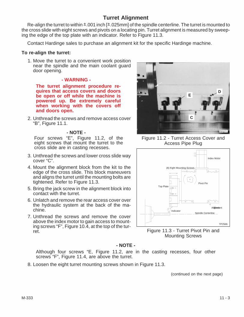
Turret AlignmentRe-align the turret to within ±.001 inch [±.025mm] of the spindle centerline. The turret is mounted to
the cross slide with eight screws and pivots on a locating pin. Turret alignment is measured by sweep-ing the edge of the top plate with an indicator. Refer to Figure 11.3.
Contact Hardinge sales to purchase an alignment kit for the specific Hardinge machine.
To re-align the turret:
1. Move the turret to a convenient work positionnear the spindle and the main coolant guarddoor opening.
- WARNING -The turret alignment procedure re-quires that access covers and doorsbe open or off while the machine ispowered up. Be extremely carefulwhen working with the covers offand doors open.
2. Unthread the screws and remove access cover“B”, Figure 11.1.
- NOTE -Four screws “E”, Figure 11.2, of theeight screws that mount the turret to thecross slide are in casting recesses.
3. Unthread the screws and lower cross slide waycover “C”.
4. Mount the alignment block from the kit to theedge of the cross slide. This block maneuversand aligns the turret until the mounting bolts aretightened. Refer to Figure 11.3.
5. Bring the jack screw in the alignment block intocontact with the turret.
6. Unlatch and remove the rear access cover overthe hydraulic system at the back of the ma-chine.
7. Unthread the screws and remove the coverabove the index motor to gain access to mount-ing screws “F”, Figure 10.4, at the top of the tur-ret.
- NOTE -Although four screws “E, Figure 11.2, are in the casting recesses, four otherscrews “F”, Figure 11.4, are above the turret.
8. Loosen the eight turret mounting screws shown in Figure 11.3.
(continued on the next page)
M-333 11 - 3
Figure 11.2 - Turret Access Cover andAccess Pipe Plug
ED
C
TP377.
Figure 11.3 - Turret Pivot Pin andMounting Screws
Index Motor
(8) Eight Mounting Screws
Top Plate
IndicatorAlignmentBlock
Spindle Centerline
TP2569.
Pivot Pin

- NOTE -Once all eight mounting screws areloosened, the jack screw in the align-ment block can maneuver the turret.The turret pivots on a locating pin setin the carriage. Refer to Figure 11.3.
9. Align the turret to within ±.001 inch [±.025 mm]of the spindle centerline as follows:A. Mount an arbor in a collet.B. Mount an indicator on the arbor.C. Jog the turret into position so that the indi-
cator sweeps the edge of the top platealong the Z axis.
D. Set the indicator to 0 (zero) and sweepthe edge of the top plate.
E. Use the jack screw in the alignment blockto pivot and hold the turret within thespecified alignment of the spindle center-line.
10. Tighten the eight turret mounting screws to 175 lb-ft [237 Nm] torque if the adapter tool from thekit, Hardinge tool CL 122AC, is used. However, if the special tool is not used, the mountingscrews must be tightened to 200 lb-ft [271 Nm] torque.
11. Sweep the edge of the top plate once again to verify that the turret alignment is within specifica-tion. If the turret is not in alignment, loosen the eight turret mounting screws and repeat steps #9and #10 until it is aligned.
- CAUTION -Do not machine stock until the way covers, access covers, and doors are in placeand fastened.
12. Mount the index motor cover in place.13. Install and latch the rear access cover.14. Unthread the screws and remove the alignment block from the carriage. Remove the arbor and
indicator.15. Raise way cover “C”, into position and fasten it with its screws.16. Fit access cover “B”, Figure 11.1, to the turret and fasten it in place.
11 - 4 M-333
Figure 11.4 - Upper Mounting Screws onthe Turret
F
F
TP378.

Turret Clamp/Unclamp (20PRS) Proximity SwitchThe turret clamp/unclamp switch is located on a bracket within the turret. It is activated by “reading”
the linear proximity of the turret index plate mounted on the top plate shaft. Turret clamp/unclampswitch “I”, is mounted on bracket “H”, Figure 11.6.
To replace and adjust the switch:
1. Move the turret to a convenient work position infront of the coolant/chip guard door. Open theguard door.
2. Power down the machine.3. Unthread the screws and take proximity switch
cover “G”, Figure 11.5, off to gain access tobracket “H”, Figure 11.6.
4. Tag the electrical connections to the switch forreassembly.
5. Unthread the screws to remove the bracket thatthe switch is mounted on.
6. Using the bracket as a reference, measure thedistance from the bracket to the tip of the switchfor approximate replacement location.
7. Carefully unthread the nuts and remove theswitch being replaced.
- NOTE -Remove the bracket each time the switch requires adjustment because of thelocation of the switch and the low torque specification.
8. Install the switch in the bracket and adjust theswitch depth per step #6.
9. Remount the bracket in the turret.10. Set the turret clamp/unclamp switch at or within
.030 in. [.76 mm] from the bottom of the turret in-dex plate.
11. After the switch has been set, remove thebracket from the turret and torque the nuts tosecure the switch. Hold the outer nut and use a13 mm socket wrench to tighten the nut closestto the sensor face to 3.5 lb-in. [0.4 Nm] torque.
12. Remount the bracket in the turret.13. Check distance between turret index plate and
the switch per step #10.14. Remove the bracket from the turret, adjust the
settings as necessary, and add Loctite® 290wicking sealant to each nut.
15. Remount the bracket in the turret.
(continued on the next page)
M-333 11 - 5
Figure 11.5 - Turret and Proximity SwitchCover
G
TP380.
Figure 11.6 - Proximity Switch and Bracket
I
H
TP2211.

16. Disconnect the wires to the old switch and connect the wires from the replacement switch perstep #4.
17. Place cover “G”, Figure 11.5, on the turret and fasten it with its screws.18. Power up the machine and test the turret top plate up/down motion.
Turret Hydraulic Valve BlockThe turret hydraulic valve block is located on top of the turret near the turret index motor, refer to
Figure 11.7. It controls the amount of “cushion” when the toothed coupling on the top plate engages(turret down). Screw “L” on the valve block limits the hydraulic flow.
To adjust the top plate “cushion”:
1. Move the turret to a convenient work position in front of the main door. Make certain that anylower axis assembly is out of the way and then press the -X pushbutton to bring the turret close tothe spindle centerline.
2. Power down the machine.3. Unlatch and remove the rear access cover and
lift it off.4. Unthread the screws and remove the cover
over the index drive motor and hydraulic valveblock “J”, Figure 11.7.
5. Loosen lock nut “K”, on adjustment screw “L”.
- NOTE -The adjustment screw only needs tobe turned one eighth of a turn duringeach adjustment trial.
6. Turn the screw either clockwise to restrict hy-draulic flow and “soften” the cushion or counter-clockwise to increase the flow and bring the topplate down with less cushion.
7. Tighten the lock nut.8. Power up the machine and test the top plate up/down action as follows:
A. Press the JOG [4] pushbutton.B. Press and make certain that the E-Stop [74] pushbutton remains down.C. Press and hold the E-Stop Reset [73] pushbutton and then press the Turret Index 1 [44]
pushbutton to raise the top plate. Press both pushbuttons again to lower the top plate.D. Listen to the clamping force as the top plate lowers and adjust the top plate “cushion” as
necessary following directions in steps #5, #6, and #7.9. Power down the machine.
10. Put the cover over the index motor and valve block and fasten it with its screws.11. Mount the rear access cover in place and fasten it.12. Power up the machine.
11 - 6 M-333
Figure 11.7 - Turret Flow Control Valve
J
L
K
TP387.
M

To replace the turret hydraulic valve block:
1. Move the turret to a convenient work position in front of the main door. Make certain that thetailstock assembly is out of the way and press the -X [67] pushbutton to bring the turret close tothe spindle centerline.
2. Power down the machine.3. Unlatch and lift off the rear access cover.4. Unthread the screws and remove the cover over the index drive motor and hydraulic valve block
“J”, Figure 11.7.5. Mark the hydraulic fittings which connect the hydraulic pressure line and the hydraulic tank line
to the valve block. Unfasten hydraulic lines from the fittings.6. Loosen two mounting screws in the valve block bracket.7. Alternately unthread the universal fittings that mount the valve block to the turret housing. It may
be necessary to unthread the screws and remove the valve block bracket.8. Unthread the screw and disconnect the molded connector (plug) from solenoid valve “M”, Figure
11.7.9. Unthread the fittings from the old valve block, use pipe sealant on the threads, and thread them
into the new valve block. Mark the fittings per step #5 for re-assembly.10. Carefully mount the valve block to the universal fittings.11. Mount the molded plug on the valve and tighten the screw.12. Use pipe sealant on the threads and fasten the hydraulic lines to the fittings per the marks from
steps #9 and #5.13. “Bleed” the hydraulic lines as follows:
A. Power up the machine.B. Press the E-Stop [74] pushbutton and make certain it is down.C. Press and hold the E-Stop Reset [73] pushbutton and press the Turret Index 1 [44]
pushbutton to raise the top plate.D. Loosen both universal fittings between the valve block and turret housing just a thread
or two to allow air to escape.E. Press and hold the E-Stop Reset [73] pushbutton and press the Turret Index 1 [44]
pushbutton to lower the top plate. Press both the pushbuttons several times to raise andlower the top plate until a ring of hydraulic fluid appears around the universal fittingthreads.
F. Make certain that the top plate is clamped (lowered) or press and hold the E-Stop Reset[73] pushbutton and press the Turret Index 1 [44] pushbutton again to lower the topplate.
G. Fasten the valve block bracket in place to support the valve block.
(continued on the next page)
M-333 11 - 7
14. Adjust the top plate “cushion” as follows:A. Power down the machine.B. Loosen lock nut “K”, Figure 11.7, on adjustment screw “L”.
- NOTE -The adjustment screw only needs to be turned approximately one eighth of a turnduring each adjustment trial.
C. Turn the screw either clockwise to restrict hydraulic flow and “soften” the cushion orcounterclockwise to increase the flow and bring the top plate down with less cushion.
D. Tighten the lock nut.E. Power up the machine and test the top plate up/down action as follows:
1) Press the JOG [4] pushbutton.2) Press and make certain that the E-Stop [74] pushbutton remains down.3) Press and hold the E-Stop Reset [73] pushbutton and then press the Turret Index
1 [44] pushbutton to raise the top plate. Press both pushbuttons again to lowerthe top plate.
4) Listen to the clamping force as the top plate lowers and adjust the top plate “cush-ion” as necessary following directions in steps A, B, C, and D.
15. Power down the machine.16. Place the cover over the index motor and valve block and fasten it with its screws.17. Put the rear access cover in place and fasten it with both latches.18. Power up the machine.
Live Tooling Attachment Maintenance
- NOTE -Do not disassemble the live tooling attachment. Return the entire assembly toHardinge Inc. if repairs are necessary.
To lubricate the live tooling attachment:
- NOTE -Grease the live tooling assembly daily with Mobiltemp® SHC 32 grease or militaryspecified Mobilgrease® 28.
1. Move the turret and index the turret top plate to a convenient position where the grease fittingnipple can be reached.
2. Open the coolant/chip guard door and, then, power down the machine.3. Wipe coolant, chips, and other contaminants from the grease fitting on the live tooling attach-
ment.4. Place the grease gun fitting on the nipple and fill the assembly with the specified grease until
grease appears around the live tool spindle seal.5. Close the coolant/chip guard door and power up the machine.6. Resume machine operation.
11 - 8 M-333

Live Tooling Drive Motor and BeltThe live tooling drive motor and belt are mounted on and at rear of the turret under a sheet metal
cover. It might be easier to work on this replacement and belt tensioning with the coolant guard doorcanopy off.
To adjust the drive motor belt:
1. Move the turret in the +Z direction and near thespindle centerline in the -X direction to be in aconvenient work position near the side accessdoor.
2. Power down the machine.3. Unlatch the right side access door and remove
the door from the machine.4. Remove the sheet metal cover from the live
tooling drive motor.5. Loosen the four screws “N”, Figure 11.8, to al-
low the motor mounting bracket to slide. Two ofthe screws are under the motor.
6. Unthread pipe plug “O”, to gain access to thebelt to test belt deflection.
- NOTE -
Location Gates Sonic TensionGage Data Deflection/Force
Live tooling drive beltmass: 0.41gf/Cmwidth: 25 mmspan: 108.0 mmtension: 147-160 N.
0.12" deflection @5.0 to 5.5 lbs.
[3.05 mm deflection@ 22.24 to 24.46 N.]
7. Adjust tension on the belt by loosening the locking nuts and unthreading, i.e. turning counter-clockwise, the screws in adjustment blocks “P”, to allow the motor mounting bracket to move to-ward the live tooling pulley or tightening the screws to move away from the live tooling pulley.
8. Adjust the belt tension until it is within specification. Tighten the locking nuts.9. Tighten the motor mounting bracket screws to 70 lb-ft [95 Nm] torque.
10. Check the live tooling drive belt deflection and make certain that it is within specification. Adjustthe drive belt tension as necessary and, then, thread in pipe plug “O”, tight.
11. Mount the sheet metal cover around the live tooling drive motor.12. Mount the side access door, close the coolant/chip guard door and power up the machine.
M-333 11 - 9
Figure 11.8 - Turret Live Tooling DriveMotor Cover
N
TP3167.
NO
N
P
P

To replace drive motor “Q”, Figure 11.9, and belt:
1. Move the turret in the +Z direction and near the spindle centerline in the -X direction to be in aconvenient work position near the side access door.
2. Power down the machine.3. Unlatch the right side access door and remove the door from the machine.4. Remove the sheet metal cover from the live tooling drive motor.5. Tag electrical connections “R” and “S”, to the
motor and encoder for re-assembly.6. Unscrew the knurled nut and pull the connec-
tors straight out from the encoder connectionand the motor connection.
7. Loosen four screws “N”, Figure 11.8, justenough to allow the motor mounting bracket toslide.
8. Release tension from the belt by loosening thelocking nuts and backing out, i.e. turning coun-terclockwise, the screws in the adjustmentblocks to allow the motor mounting bracket tomove toward the live tooling pulley.
9. Be aware of the location of the electrical con-nection outlets for “R” and “S” in relation to themotor mounting bracket before removing themotor from it.
10. Unthread four screws “T”, Figure 11.9, from the motor flange and remove the motor.11. Check the condition of the drive belt. Replace it if necessary.12. Mount and adjust the live tooling drive motor as follows:
A. Align the electrical connection outlets per step #9, put the drive belt on both pulleys andremount the live tooling drive motor on the motor bracket. Tighten the four screws to 70lb-ft [95 Nm] torque.
B. Unthread large pipe plug “O”, Figure 11.8, to gain access to the live tooling drive belt.
- NOTE -
Location Gates Sonic TensionGage Data Deflection/Force
Live tooling drive beltmass: 0.41gf/Cmwidth: 25 mmspan: 108.0 mmtension: 147-160 N.
0.12" deflection @5.0 to 5.5 lbs.
[3.05 mm deflection@ 22.24 to 24.46 N.]
C. Align the drive belt on both pulleys, place tension on the drive belt by threading in (turn-ing clockwise) the screws in adjustment blocks “P”.
D. Tighten the motor mounting bracket screws to 70 lb-ft [95 Nm] torque.E. Check the live tooling drive belt deflection and make certain that it is within specification.
Adjust the drive belt tension as necessary.F. Thread in large pipe plug “O”, tight.G. Tighten the locking nuts on both adjustment blocks to secure the belt tension screws.
11 - 10 M-333
Figure 11.9 - Live Tooling Drive Motor
Q
R
S
TP2225.
T
T

13. Connect the motor and encoder electrical sources (“R” and “S”) per the tags in step #5. Tightenthe knurled nuts to secure the connections.
14. Mount the sheet metal cover around the live tooling drive motor.15. Before powering up the machine, remount all the covers and close the access doors.16. Power up the machine and Home the axes.17. Press the Zero Return [69] and Turret 1 Index [44] pushbuttons; the top plate will unclamp, index
to the selected station, and clamp. Index the top plate several times to see that it is working prop-erly.
18. If necessary, mount a live tooling attachment and make adjustments as necessary.
Turret Top PlateTooling is mounted to the turret top plate and, if the machine has live tooling, to the live tooling stop.
When the top plate is replaced, the toothed coupling on the bottom of the top plate must be mounted tothe replacement plate.
- WARNING -This procedure requires that the serviceman work on the turret top plate while themachine is powered up. Be extremely careful not to power down the machine oractivate the control without being clear of the top plate and turret.
To remove the turret top plate:
1. Press the Jog pushbutton.2. Move the turret to a convenient work position in
front of the main door. Make certain that thetailstock assembly is out of the way and thenpress the -X directional pushbutton to bring theturret close to the spindle centerline.
3. Index the top plate to Station 1 as follows:A. Make certain that the control is in Jog
mode.B. Turn the turret station switch [47] to Sta-
tion 1.C. Press Zero Return [69] pushbutton and si-
multaneously press Turret Index 1 [44]pushbutton.
D. Open the coolant/chip guard door andpower down the machine.
4. Unclamp (raise) the top plate as follows:A. Press the E-Stop [74] pushbutton and
make certain that the button is down.B. Press and hold the E-Stop Reset [73]
pushbutton while pressing the Turret Index1 [44] pushbutton to unclamp (raise) thetop plate.
(continued on the next page)
M-333 11 - 11
Figure 11.10 - Top Plate with Live Tooling
S
TP391.
X
V
U
W

- NOTE -Tooling does not have to be removedfrom the top plate; however, if the ma-chine has live tooling, this tooling mustbe removed.
5. On machines without the live tooling option,loosen the set screws to remove tool stop ring“Z”, Figure 11.11, and unthread screws to re-move indicator plate “Y”.On machines with the live tooling option:A. Remove tooling “U”, Figure 11.10, or the
plugs from the live tooling stop before re-moving the tool stop ring.
B. Remove indicator plate “V”, from the topof the live tooling ring.
C. Unthread the nut so that the washer,bevel gear, key, shim(s), and bearingspacer can be removed from the live tool-ing shaft.
D. Unfasten twelve buttonhead screws to re-move the live tooling stop.
E. Loosen the set screws and remove toolstop ring “W”.
6. Mark the shaft and top plate with a felt tippedpen or paint for re-installation reference.
7. Remove two dowel pins ‘A", Figure 11.12, fromthe inner bolt circle by using a screw through astack of washers.
8. Install top plate lifting bracket, Hardinge PartNumber CL-0000122-AO, on a tool station atthe top edge of the top plate.
9. Move a chain hoist or gantry into position overthe machine.Fasten a strap through the eyebolt on the lift-ing bracket and fasten it to the hoist.
10. Take up the slack in the strap.11. Remove eight M12 screws “B”, from the inner
bolt circle on the face of the top plate.12. Pull the top plate approximately 1 inch [25 mm]
off the index shaft and carefully remove it fromthe turret.
11 - 12 M-333
Figure 11.11 - Standard Top Plate(without Live Tooling)
Z
Y
TP392.
Figure 11.12 - Turret Top Plate
B
A
TP393.
C

To remove and re-install the top plate coupling:
- NOTE -The 10 station top plates have 10 teethon the coupling and 12 station topplates have 12 teeth on the coupling.
1. Remove coupling screw access plugs “C”, Fig-ure 11.12, from the outer bolt circle.
2. Unthread the twelve M8 screws in the outer boltcircle to remove the coupling.
3. Replace the top plate seal and/or coupling asneeded.
4. Stone and wipe the coupling and top plate cleanto fit them together as necessary before re-as-sembly. Put a light coat of Bell-Ray Molylube®
Anti-Seize compound on the surfaces thatmate.
5. Re-install the coupling on the top plate as fol-lows:A. Put the coupling into the top plate.B. Turn the coupling until the coupling clear-
ance holes are aligned with the threadedholes in the top plate.
C. Fasten the coupling to the top plate withthe twelve M8 screws finger tight.
To install the top plate:
1. Coat the seal ring and seal with a light coat of die makers grease. Mobiltemp® SHC 32 or militaryspecified Mobilgrease® 28 may also be used.
2. Re-install the top plate on the index shaft while aligning the reference mark from step #6, “To re-move the turret top plate”.
3. Rotate the top plate until the dowel pin holes are visually aligned.4. Put Loctite® #242 threadlocker on the screw threads of eight M12 top plate mounting screws.
Thread the screws into the inner bolt circle holes, but do not tighten them.5. Install the dowel pins.6. Diagonally tighten top plate screws “W’, Figure 11.13, to 50 Ib-ft [68 N-m] torque.7. Remove the strap, move the hoist or gantry from the machine, and remove the top plate lifting
bracket from the top plate.
(continued on the next page)
M-333 11 - 13
Figure 11.13 - Top Plate w/Coupling Ringsand Seal
TP394

- NOTE -Visually align the coolant opening in the bottom of the top plate with the coolantbushing, indicated in Figure 11.2, before clamping the top plate. Unthread pipeplug “D”, Figure 11.2, and use a hex tool up through the opening into the end of ashaft in the gear box and manually rotate the top plate, as necessary, to align theopening with the coolant bushing.
8. Clamp (lower) the top plate by pressing and holding the E-Stop Reset [73] pushbutton whilepressing the Turret Index 1 [44] pushbutton.
9. Zero return the top plate to Station #1 as follows:A. Turn the E-Stop [74] pushbutton clockwise to release it and then press the E-Stop Reset
[73] pushbutton.B. Make certain that the machine is in JOG mode.C. Press and hold the Axis Zero Return [69] pushbutton and press the Turret Index 1 [44]
pushbutton.10. Adjust the top plate to achieve runout within .003 inch [.076 mm] for machines without live tooling
and .0015 inch [.038 mm] for machines with live tooling as follows:A. Mount an indicator on an arbor in a collet, Figure 11.14. An indicator with a magnetic
stand could also be used.B. Indicate the bottom of a tool holder slot by
jogging the turret in the -X and +X direc-tion while reading the indicator.
11. Align the top plate as follows:A. Install Hardinge bore gauge
CL-0000122-AH for the English top plateor bore gauge CL-0000122-AI for the Met-ric top plate. If a bore gauge is not avail-able, use a large enough standard roundbore tool holder to effectively read thebore.
B. Sweep the bore as in Figure 11.14.C. Set the bore to .0015 inch [.038 mm] low -
down toward the rails - on any station asfollows:1) Shut down the hydraulic system by pressing the E-Stop [74] pushbutton and turning
OFF the air valve at the rear of the machine.
- NOTE -When the machine is in an Emergency Stop condition and low air is sensed, thehydraulic system is shut down. This condition relieves pressure on the top plate.
2) Loosen the M-8 screws that secure the coupling to the top plate just enough to en-able the top plate to be adjusted.
3) Rotate the top plate to align it within specifications.4) Tighten the coupling screws to 25 lb-ft [34 Nm] torque.
D. Recheck the top plate specifications per steps #11.A and B, above.
11 - 14 M-333
Figure 11.14 - Top Plate Alignment
TP395.
E. Diagonally remove the coupling M-8 screws one at a time; put Loctite® #242 threadlocker on the threads; re-insert the screw and tighten it to 25 lb-ft [34 Nm] torque.
F. Put Loctite #222 threadlocker or pipe dope on coupling access plugs, “C”, Figure 11.12,and install them flush or below the top plate surface.
12. Fasten the tool stop and indicator plate in place. If the machine has live tooling, mount the livetooling stop and the tool stop ring to the top plate.
13. Re-install the live tooling parts in the live tooling stop as follows:A. Put the bearing spacer on the shaft.B. Place the key in the keyway.C. Align the beveled gear on the shaft and key.D. Put on the washer and tighten the nut to 20 lb-ft [27 Nm] torque.
14. Install indicator plate “V”, Figure 11.10.15. Mount either tooling “U”, or the plugs to the live tooling stop.16. Power up the machine.
- NOTES -
M-333 11 - 15

- NOTES -
11 - 16 M-333

CHAPTER 12 - TAILSTOCKS
IntroductionThe CONQUEST® T51, T51SP, and T65 series machines have a hydraulically operated, program-
mable tailstock option. The CONQUEST T65-L lathes are available with a manually positionedtailstock; information for the manually positioned tailstock follows the programmable positioning tail-stocks. The tailstocks provide additional support and reduce part deflection when machining longparts. This allows for closer tolerances, better surface finishes, and higher speeds and feeds thanwould otherwise be possible.
Programmable Positioning TailstockA hydraulic cylinder extends and retracts the tailstock assembly. The hydraulic module is located
on a platform at the rear of the machine. Tailstock movement can be controlled automatically from thepart program or manually by using the tailstock pushbuttons on the machine control panel.
There are two rates of motion:
1. The rapid traverse rate is approximately 300 in/min [7620 mm/min].2. The adjustable rate of feed.
The tailstock has an eccentric bushing which will accept a live center with a #4 Morse taper. Theforce applied to the workpiece is controlled by hydraulic oil pressure which is regulated by valve “B”,Figure 12.1. Gauge “D” indicates the pressure in psi and bars. Table 1 lists the approximate force inpounds (lbs) and dekanewtons (daN) which will be applied to the workpiece for a given gauge pres-sure. Detailed information about hydraulic system components appears in Chapter 5 - HydraulicModule.
- CAUTION -The tailstock force must be above200 psi [13.8 bars] for maximum op-erating safety and to ensure that thehydraulic components function cor-rectly.
Always make certain that the turretis in a safe index position beforemoving the tailstock toward thespindle.
The tailstock design incorporates a “safety shear”feature to limit the damage if there is contact betweenthe tailstock and the turret or its tooling. If contact ismade, the “safety shear” feature allows the tailstockto pivot away. Refer to Page 12-5 for instructions onre-aligning the tailstock.
M-333 12 - 1
Figure 12.1 - Tailstock HydraulicRegulators and Gauge
TP3171.
B
C
A
D
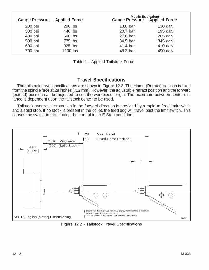
Travel SpecificationsThe tailstock travel specifications are shown in Figure 12.2. The Home (Retract) position is fixed
from the spindle face at 28 inches [712 mm]. However, the adjustable retract position and the forward(extend) position can be adjusted to suit the workpiece length. The maximum between-center dis-tance is dependent upon the tailstock center to be used.
Tailstock overtravel protection in the forward direction is provided by a rapid-to-feed limit switchand a solid stop. If no stock is present in the collet, the feed dog will travel past the limit switch. Thiscauses the switch to trip, putting the control in an E-Stop condition.
12 - 2 M-333
Figure 12.2 - Tailstock Travel Specifications
TI1621
Due to fact that this value may vary slightly from machine to machine,only approximate values are listed.This dimension is dependent upon tailstock center used.NOTE: English [Metric] Dimensioning
†
‡
†
† 28 Max. Travel[712] (Fixed Home Position)
9 Min.Travel[229] (Solid Stop)4.25
[107.95]
‡
Gauge Pressure Applied Force
13.8 bar 130 daN20.7 bar 195 daN27.6 bar 265 daN34.5 bar 345 daN41.4 bar 410 daN48.3 bar 490 daN
Gauge Pressure Applied Force
200 psi 290 lbs300 psi 440 lbs400 psi 600 lbs500 psi 775 lbs600 psi 925 lbs700 psi 1100 lbs
Metric Equivalent
Table 1 - Applied Tailstock Force

Turning the Tailstock Function ON or OFF
- CAUTION -Hardinge recommends that the tailstock function be turned OFF when jobs donot require the tailstock. This forces the tailstock to the Home position and elimi-nates the possibility of unwanted tailstock motion. Turning off the machine alsoreduces the lubricator oil consumption. When the tailstock is turned off, thetailstock receives lubrication once every 50 minutes (30 cycles).
Refer to the Operator’s manual (M-332) to turn the tailstock option ON or OFF. The tailstock func-tion must be ON before attempting to run a program that commands tailstock motion.
ON/OFF Procedure
1. Press Emergency Stop [74] pushbutton. Be certain it latches in the down position.2. Press and hold the E-Stop Reset [73] pushbutton.3. Check the indicator light next to +LA [60] pushbutton.
If the light is ON, the tailstock function is ON.If the light is OFF, the tailstock function is OFF.
If necessary, press +LA [60] pushbutton to change the state of the tailstock function to ei-ther ON or OFF.
4. Release the E-Stop Reset [73] pushbutton.5. Pull out Emergency Stop [74] pushbutton.6. Pull out further Emergency Stop [74] pushbutton while simultaneously pressing E-Stop Reset
[73] pushbutton. Release the pushbuttons.
Tailstock PositionsThere are three tailstock positions recognized by the machine control.
Fixed HOME Position (Retract)
The fixed Home position is located approximately 28 inches [712 mm] from the spindle face. Thisposition is NOT adjustable. Refer to Figure 12.2. Refer to Chapter 6 - Tailstocks of the Operator’sManual (M-332) on page 6-6 for information on moving the tailstock to the fixed Home position. TheLA Home indicator light will be ON when the tailstock is at the fixed Home position.
Adjustable HOME Position (Retract)
- NOTE -When doing maintenance, it may be desirable to set the adjustable Home to thesame position as the fixed Home.
The adjustable Home position is intended to minimize tailstock motion, resulting in lower cycletimes. The machine operator establishes the adjustable Home position by locating the adjustableHome limit switch dog as needed. Refer to “Tailstock Set Up” in Chapter 6 - Tailstocks of the Opera-tor’s Manual (M-332) on page 6-8 for information on setting the adjustable Home position. The LAHome indicator light will blink when the tailstock is in the adjustable Home position.
(continued on the next page)
M-333 12 - 3
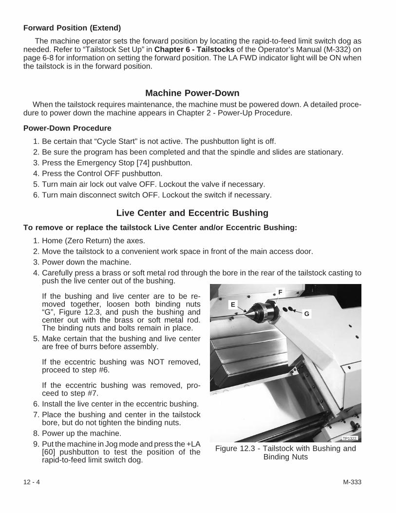
Forward Position (Extend)
The machine operator sets the forward position by locating the rapid-to-feed limit switch dog asneeded. Refer to “Tailstock Set Up” in Chapter 6 - Tailstocks of the Operator’s Manual (M-332) onpage 6-8 for information on setting the forward position. The LA FWD indicator light will be ON whenthe tailstock is in the forward position.
Machine Power-DownWhen the tailstock requires maintenance, the machine must be powered down. A detailed proce-
dure to power down the machine appears in Chapter 2 - Power-Up Procedure.
Power-Down Procedure
1. Be certain that “Cycle Start” is not active. The pushbutton light is off.2. Be sure the program has been completed and that the spindle and slides are stationary.3. Press the Emergency Stop [74] pushbutton.4. Press the Control OFF pushbutton.5. Turn main air lock out valve OFF. Lockout the valve if necessary.6. Turn main disconnect switch OFF. Lockout the switch if necessary.
Live Center and Eccentric Bushing
To remove or replace the tailstock Live Center and/or Eccentric Bushing:
1. Home (Zero Return) the axes.2. Move the tailstock to a convenient work space in front of the main access door.3. Power down the machine.4. Carefully press a brass or soft metal rod through the bore in the rear of the tailstock casting to
push the live center out of the bushing.
If the bushing and live center are to be re-moved together, loosen both binding nuts“G”, Figure 12.3, and push the bushing andcenter out with the brass or soft metal rod.The binding nuts and bolts remain in place.
5. Make certain that the bushing and live centerare free of burrs before assembly.
If the eccentric bushing was NOT removed,proceed to step #6.
If the eccentric bushing was removed, pro-ceed to step #7.
6. Install the live center in the eccentric bushing.7. Place the bushing and center in the tailstock
bore, but do not tighten the binding nuts.8. Power up the machine.9. Put the machine in Jog mode and press the +LA
[60] pushbutton to test the position of therapid-to-feed limit switch dog.
12 - 4 M-333
Figure 12.3 - Tailstock with Bushing andBinding Nuts
GE
F
TP1322.

10. Press the +LA [60] pushbutton again and move the tailstock to the Home position or adjustablehome position.
- NOTE -Align the tailstock within ±.001 inch [.025 mm] of the center with the hydraulicpressure set at 350 psi [24.1 bars].
11. Chuck a test arbor in the machine spindle.12. Adjust the rapid-to-feed limit switch dog to cause the tailstock to slow before making contact with
the test arbor.13. Press the -LA [58] pushbutton to move the tailstock to position the live center against the end of
the test arbor.14. Check to be sure that the tailstock hydraulic pressure is set at 350 psi [24.1 bars].15. Check the alignment between the live center and the test arbor. If the center is out of alignment,
rotate the eccentric bushing to bring the center into alignment.16. Tighten binding nuts “G”.
Tailstock AlignmentThe tailstock is bored in place for accuracy. It rides on linear guideways and is protected by the
“safety shear” design of the tailstock carriage (base). The tailstock pivots on the tailstock base if theturret or tools make contact with it. The breakaway switch is active when the tailstock is in place andputs the control into an Emergency Stop (E-Stop) condition when the tailstock is moved out of align-ment.
Adjustment screw “L”, Figure 12.5, in alignment stop block “K” limits the pivot rotation of thetailstock when it is being repositioned. After the tailstock is positioned, set the tailstock pressuregauge at 350 psi [24.1 bars] and re-align the eccentric bushing to within ±.001 inch [.025 mm].
To re-align the tailstock:
- WARNING -DO NOT program tailstock motionuntil the tailstock re-alignment hasbeen completed.
1. Make certain that the control is in the E-Stopcondition. The program should have stoppedand the E-Stop light should be flashing.
2. Press and hold the E-Stop Reset [73]pushbutton and press +X [63] pushbutton to jogthe turret and its tools well clear of the tailstock.
3. Remove the workpiece and power down themachine.
4. Open the main coolant guard door to the turretand tailstock.
(continued on the next page)
M-333 12 - 5
Figure 12.4 - Tailstock Alignment
H
TP1322.

5. Unlatch and lift off the right side access door from the machine.6. Remove alignment stop block cover “H”, Figure 12.4, from the tailstock.7. Have a work partner put a 6 feet [2 meters] long brass or soft metal bar into the back of the live
center opening in the tailstock. Carefully tap the bar to loosen the live center and, then, removethe center from the eccentric bushing.
8. Keep the brass or soft metal bar in the opening and apply downward pressure on it to hold thetailstock in place while loosening mounting screw “M”, Figure 12.6, and mounting screws “I” and“J”, Figure 12.5.
9. Loosen pivot screw “N”, Figure .6, only if the tailstock doesn’t re-align when the mounting screwsare loosened.
10. Carefully pivot the tailstock near alignment by applying more downward pressure on the brass orsoft metal bar and some pressure on the tailstock nose until adjustment screw “L”, Figure 12.5,stops upward movement.
11. Hold the tailstock in place and tighten pivot screw “N”, to 15 lb-ft [20 Nm] torque. Then tightenmounting screws “I”, “J”, and “M” to the same torque. Remove the brass or soft metal bar fromthe tailstock opening.
- NOTE -Align the tailstock within ±.001 inch [.025 mm] of the spindle centerline with thehydraulic pressure set at 350 psi [24.1 bars].
12. Align the tailstock as follows:A. Install a dead center in the eccentric bushing in the tailstock.B. Make certain that tailstock solid stop block “O”, Figure 12.7, is set to the far left.C. Loosen knobs and move the adjustment Home and rapid-to-feed dogs “Q” and “R”, to
the far right. Tighten the knobs.D. Power up the machine. All doors may have to be closed to activate the Jog mode.E. Simultaneously press Zero Return [69] pushbutton and +LA [60] pushbutton to Home the
tailstock. Press JOG [4] pushbutton to clear the homing sequence and put the control inJOG mode.
12 - 6 M-333
Figure 12.5 - Stop Block and Adjustment Screw(Viewed from the Front of the Machine)
TP401.
IJ
K
L
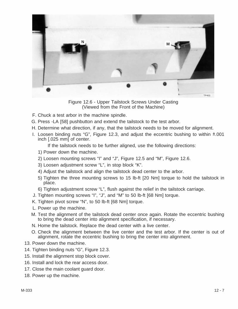
F. Chuck a test arbor in the machine spindle.G. Press -LA [58] pushbutton and extend the tailstock to the test arbor.H. Determine what direction, if any, that the tailstock needs to be moved for alignment.I. Loosen binding nuts “G”, Figure 12.3, and adjust the eccentric bushing to within ±.001
inch [.025 mm] of center.If the tailstock needs to be further aligned, use the following directions:
1) Power down the machine.2) Loosen mounting screws “I” and “J”, Figure 12.5 and “M”, Figure 12.6.3) Loosen adjustment screw “L”, in stop block “K”.4) Adjust the tailstock and align the tailstock dead center to the arbor.5) Tighten the three mounting screws to 15 lb-ft [20 Nm] torque to hold the tailstock in
place.6) Tighten adjustment screw “L”, flush against the relief in the tailstock carriage.
J. Tighten mounting screws “I”, “J”, and “M” to 50 lb-ft [68 Nm] torque.K. Tighten pivot screw “N”, to 50 lb-ft [68 Nm] torque.L. Power up the machine.M. Test the alignment of the tailstock dead center once again. Rotate the eccentric bushing
to bring the dead center into alignment specification, if necessary.N. Home the tailstock. Replace the dead center with a live center.O. Check the alignment between the live center and the test arbor. If the center is out of
alignment, rotate the eccentric bushing to bring the center into alignment.13. Power down the machine.14. Tighten binding nuts “G”, Figure 12.3.15. Install the alignment stop block cover.16. Install and lock the rear access door.17. Close the main coolant guard door.18. Power up the machine.
M-333 12 - 7
Figure 12.6 - Upper Tailstock Screws Under Casting(Viewed from the Front of the Machine)
TP402.
MN
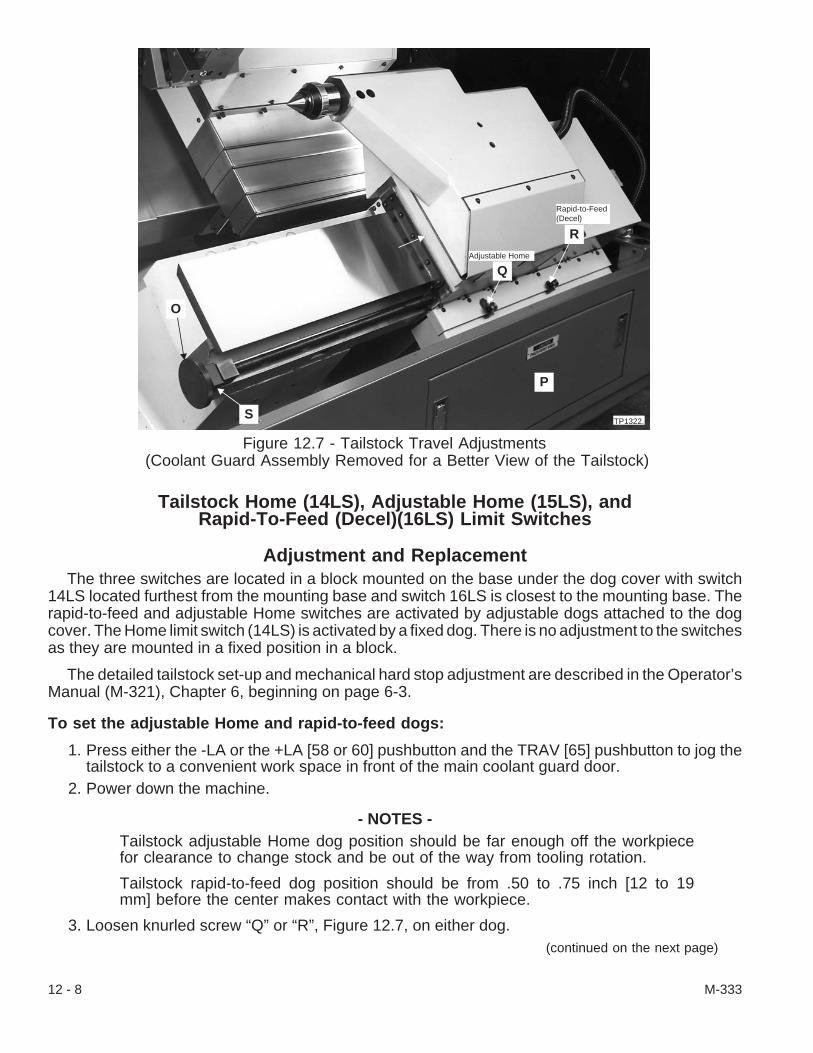
Tailstock Home (14LS), Adjustable Home (15LS), andRapid-To-Feed (Decel)(16LS) Limit Switches
Adjustment and ReplacementThe three switches are located in a block mounted on the base under the dog cover with switch
14LS located furthest from the mounting base and switch 16LS is closest to the mounting base. Therapid-to-feed and adjustable Home switches are activated by adjustable dogs attached to the dogcover. The Home limit switch (14LS) is activated by a fixed dog. There is no adjustment to the switchesas they are mounted in a fixed position in a block.
The detailed tailstock set-up and mechanical hard stop adjustment are described in the Operator’sManual (M-321), Chapter 6, beginning on page 6-3.
To set the adjustable Home and rapid-to-feed dogs:
1. Press either the -LA or the +LA [58 or 60] pushbutton and the TRAV [65] pushbutton to jog thetailstock to a convenient work space in front of the main coolant guard door.
2. Power down the machine.
- NOTES -Tailstock adjustable Home dog position should be far enough off the workpiecefor clearance to change stock and be out of the way from tooling rotation.
Tailstock rapid-to-feed dog position should be from .50 to .75 inch [12 to 19mm] before the center makes contact with the workpiece.
3. Loosen knurled screw “Q” or “R”, Figure 12.7, on either dog.(continued on the next page)
12 - 8 M-333
Figure 12.7 - Tailstock Travel Adjustments(Coolant Guard Assembly Removed for a Better View of the Tailstock)
O
P
Q
R
TP1322.
Adjustable Home
Rapid-to-Feed(Decel)
S
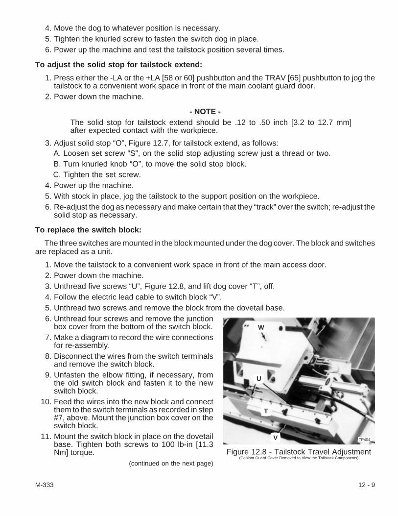
4. Move the dog to whatever position is necessary.5. Tighten the knurled screw to fasten the switch dog in place.6. Power up the machine and test the tailstock position several times.
To adjust the solid stop for tailstock extend:
1. Press either the -LA or the +LA [58 or 60] pushbutton and the TRAV [65] pushbutton to jog thetailstock to a convenient work space in front of the main coolant guard door.
2. Power down the machine.
- NOTE -The solid stop for tailstock extend should be .12 to .50 inch [3.2 to 12.7 mm]after expected contact with the workpiece.
3. Adjust solid stop “O”, Figure 12.7, for tailstock extend, as follows:A. Loosen set screw “S”, on the solid stop adjusting screw just a thread or two.B. Turn knurled knob “O”, to move the solid stop block.C. Tighten the set screw.
4. Power up the machine.5. With stock in place, jog the tailstock to the support position on the workpiece.6. Re-adjust the dog as necessary and make certain that they “track” over the switch; re-adjust the
solid stop as necessary.
To replace the switch block:
The three switches are mounted in the block mounted under the dog cover. The block and switchesare replaced as a unit.
1. Move the tailstock to a convenient work space in front of the main access door.2. Power down the machine.3. Unthread five screws “U”, Figure 12.8, and lift dog cover “T”, off.4. Follow the electric lead cable to switch block “V”.5. Unthread two screws and remove the block from the dovetail base.6. Unthread four screws and remove the junction
box cover from the bottom of the switch block.7. Make a diagram to record the wire connections
for re-assembly.8. Disconnect the wires from the switch terminals
and remove the switch block.9. Unfasten the elbow fitting, if necessary, from
the old switch block and fasten it to the newswitch block.
10. Feed the wires into the new block and connectthem to the switch terminals as recorded in step#7, above. Mount the junction box cover on theswitch block.
11. Mount the switch block in place on the dovetailbase. Tighten both screws to 100 lb-in [11.3Nm] torque.
(continued on the next page)
M-333 12 - 9
Figure 12.8 - Tailstock Travel Adjustment(Coolant Guard Cover Removed to View the Tailstock Components)
W
U
T
V TP404.
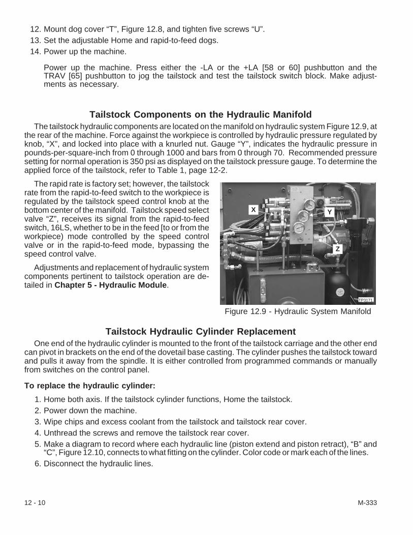
12. Mount dog cover “T”, Figure 12.8, and tighten five screws “U”.13. Set the adjustable Home and rapid-to-feed dogs.14. Power up the machine.
Power up the machine. Press either the -LA or the +LA [58 or 60] pushbutton and theTRAV [65] pushbutton to jog the tailstock and test the tailstock switch block. Make adjust-ments as necessary.
Tailstock Components on the Hydraulic ManifoldThe tailstock hydraulic components are located on the manifold on hydraulic system Figure 12.9, at
the rear of the machine. Force against the workpiece is controlled by hydraulic pressure regulated byknob, “X”, and locked into place with a knurled nut. Gauge “Y”, indicates the hydraulic pressure inpounds-per-square-inch from 0 through 1000 and bars from 0 through 70. Recommended pressuresetting for normal operation is 350 psi as displayed on the tailstock pressure gauge. To determine theapplied force of the tailstock, refer to Table 1, page 12-2.
The rapid rate is factory set; however, the tailstockrate from the rapid-to-feed switch to the workpiece isregulated by the tailstock speed control knob at thebottom center of the manifold. Tailstock speed selectvalve “Z”, receives its signal from the rapid-to-feedswitch, 16LS, whether to be in the feed [to or from theworkpiece) mode controlled by the speed controlvalve or in the rapid-to-feed mode, bypassing thespeed control valve.
Adjustments and replacement of hydraulic systemcomponents pertinent to tailstock operation are de-tailed in Chapter 5 - Hydraulic Module.
Tailstock Hydraulic Cylinder ReplacementOne end of the hydraulic cylinder is mounted to the front of the tailstock carriage and the other end
can pivot in brackets on the end of the dovetail base casting. The cylinder pushes the tailstock towardand pulls it away from the spindle. It is either controlled from programmed commands or manuallyfrom switches on the control panel.
To replace the hydraulic cylinder:
1. Home both axis. If the tailstock cylinder functions, Home the tailstock.2. Power down the machine.3. Wipe chips and excess coolant from the tailstock and tailstock rear cover.4. Unthread the screws and remove the tailstock rear cover.5. Make a diagram to record where each hydraulic line (piston extend and piston retract), “B” and
“C”, Figure 12.10, connects to what fitting on the cylinder. Color code or mark each of the lines.6. Disconnect the hydraulic lines.
12 - 10 M-333
Figure 12.9 - Hydraulic System Manifold
X
Z
Y
TP3171.
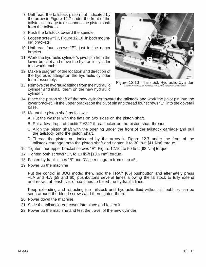
7. Unthread the tailstock piston nut indicated bythe arrow in Figure 12.7 under the front of thetailstock carriage to disconnect the piston shaftfrom the tailstock.
8. Push the tailstock toward the spindle.9. Loosen screw “D”, Figure 12.10, in both mount-
ing brackets.10. Unthread four screws “E”, just in the upper
bracket.11. Work the hydraulic cylinder’s pivot pin from the
lower bracket and move the hydraulic cylinderto a workbench.
12. Make a diagram of the location and direction ofthe hydraulic fittings on the hydraulic cylinderfor re-assembly.
13. Remove the hydraulic fittings from the hydrauliccylinder and install them on the new hydrauliccylinder.
14. Place the piston shaft of the new cylinder toward the tailstock and work the pivot pin into thelower bracket. Fit the upper bracket on the pivot pin and thread four screws “E”, into the dovetailbase.
15. Mount the piston shaft as follows:A. Put the washer with the flats on two sides on the piston shaft.B. Put a few drops of Loctite® #242 threadlocker on the piston shaft threads.C. Align the piston shaft with the opening under the front of the tailstock carriage and pull
the tailstock onto the piston shaft.D. Thread the piston nut indicated by the arrow in Figure 12.7 under the front of the
tailstock carriage, onto the piston shaft and tighten it to 30 lb-ft [41 Nm] torque.16. Tighten four upper bracket screws “E”, Figure 12.10, to 50 lb-ft [68 Nm] torque.17. Tighten both screws “D”, to 10 lb-ft [13.6 Nm] torque.18. Fasten hydraulic lines “B” and “C”, per diagram from step #5.19. Power up the machine
Put the control in JOG mode; then, hold the TRAY [65] pushbutton and alternately press+LA and -LA [58 and 60] pushbuttons several times allowing the tailstock to fully extendand retract at least five, or six times to bleed the hydraulic lines.
Keep extending and retracting the tailstock until hydraulic fluid without air bubbles can beseen around the bleed screws and then tighten them.
20. Power down the machine.21. Slide the tailstock rear cover into place and fasten it.22. Power up the machine and test the travel of the new cylinder.
M-333 12 - 11
Figure 12.10 - Tailstock Hydraulic Cylinder(Coolant Guard Cover Removed to View the Tailstock Components)
TP406.
A D
B
C
E
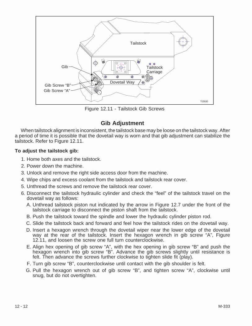
Gib AdjustmentWhen tailstock alignment is inconsistent, the tailstock base may be loose on the tailstock way. After
a period of time it is possible that the dovetail way is worn and that gib adjustment can stabilize thetailstock. Refer to Figure 12.11.
To adjust the tailstock gib:
1. Home both axes and the tailstock.2. Power down the machine.3. Unlock and remove the right side access door from the machine.4. Wipe chips and excess coolant from the tailstock and tailstock rear cover.5. Unthread the screws and remove the tailstock rear cover.6. Disconnect the tailstock hydraulic cylinder and check the “feel” of the tailstock travel on the
dovetail way as follows:A. Unthread tailstock piston nut indicated by the arrow in Figure 12.7 under the front of the
tailstock carriage to disconnect the piston shaft from the tailstock.B. Push the tailstock toward the spindle and lower the hydraulic cylinder piston rod.C. Slide the tailstock back and forward and feel how the tailstock rides on the dovetail way.D. Insert a hexagon wrench through the dovetail wiper near the lower edge of the dovetail
way at the rear of the tailstock. Insert the hexagon wrench in gib screw “A”, Figure12.11, and loosen the screw one full turn counterclockwise.
E. Align hex opening of gib screw “A”, with the hex opening in gib screw “B” and push thehexagon wrench into gib screw “B”. Advance the gib screws slightly until resistance isfelt. Then advance the screws further clockwise to tighten slide fit (play).
F. Turn gib screw “B”, counterclockwise until contact with the gib shoulder is felt.G. Pull the hexagon wrench out of gib screw “B”, and tighten screw “A”, clockwise until
snug, but do not overtighten.
12 - 12 M-333
Figure 12.11 - Tailstock Gib Screws
TI2630
Gib
Gib Screw “B”Gib Screw “A”
Dovetail Way
Tailstock
TailstockCarriage
- CAUTION -Excessive gib pressure or drag does not improve machine performance and maybe damaging to the dovetail way and/or hydraulic cylinder.
H. Move the tailstock on the dovetail way and “feel” the tailstock travel. The tailstock travelshould have slight drag, but should not bind.
I. Mount the piston shaft as follows:1) Put the washer with the flats on two sides on the piston shaft.2) Put a few drops of Loctite® #242 threadlocker on the piston shaft threads.3) Align the piston shaft with the opening under the front of the tailstock carriage and
pull the tailstock onto the piston shaft.4) Thread the piston nut indicated by the arrow in Figure 12.7 under the front of the
tailstock carriage, onto the piston shaft and tighten it to 30 lb-ft [41 Nm] torque.7. Mount the tailstock rear cover on the tailstock carriage.8. Mount and lock the right side access door on the machine.9. Power up the machine.
10. Test the tailstock travel by extending and retracting the tailstock several times. Adjust thetailstock gibs as necessary.
11. Test the alignment of the tailstock dead center once again. Rotate the eccentric bushing to bringthe dead center into alignment specification, if necessary.
12. Replace the dead center with a live center. Check the alignment between the live center and thetest arbor. If the center is out of alignment, rotate the eccentric bushing to bring the center intoalignment. Tighten the binding nuts.
MANUALLY POSITIONED TAILSTOCK(CONQUEST® T65-L Lathe Only)
- NOTEInformation relating to tailstocks for CONQUEST T51, T51SP, and T65 lathesbegins at the front of this chapter.
IntroductionCONQUEST T65-L lathes are available with a manually positioned tailstock equipped with a hy-
draulically operated, programmable quill. The hydraulic unit and air panel are located at the rear of themachine.
The tailstock quill is advanced and retracted by means of a hydraulic cylinder. Tailstock quill motioncan be controlled automatically from the part program or manually using pushbuttons on the operatorcontrol panel. The force applied to the workpiece by the tailstock quill is adjustable. Refer to page12-16 for information on adjusting the applied force.
The tailstock quill is designed to accept a live center with a #4 Morse taper.
The tailstock incorporates a “safety shear” feature to prevent damage to the tooling, turret,tailstock, and linear ways should the turret contact the tailstock. If contact is made between thetailstock and turret, the “safety shear” feature allows the tailstock to be pivoted away from the turret.
M-333 12 - 13

Tailstock PositioningThe machine operator must manually position the tailstock assembly at the desired location.
- CAUTION -The tailstock quill is capable of extending 5.25 inches [133.4 mm] from the Re-tract position. To ensure the desired force is being applied to the workpiece bythe tailstock quill, the recommended maximum tailstock quill extension duringmachining is 5 inches [127 mm].
1. Press the Jog [4] pushbutton to activate Jog mode.2. Jog the turret away from the spindle and tailstock.3. Mount a workpiece in the machine spindle at the desired length.4. Press the Collet/Chuck [53] pushbutton to close the workholding device.5. If necessary, install the live center in the tailstock quill.6. Press the Auxiliary Function [10] pushbutton to release the hydraulic clamping pressure on the
tailstock and activate the “air lift” feature to enable tailstock movement.7. Slide the tailstock assembly to the desired location.8. Press the Auxiliary Function [10] pushbutton to deactivate the “air lift” feature and engage the
hydraulic clamping pressure on the tailstock9. Check the position of the tailstock assembly by pressing the -LA [58] pushbutton to feed the
tailstock center onto the workpiece.
If the tailstock position is acceptable, this procedure is complete. If the tailstock position isnot acceptable, repeat steps #6 through 9.
10. Check the hydraulic pressure setting for the tailstock quill and adjust as needed. Refer to “Hy-draulic Pressure Adjustment”, on page 12-16.
12 - 14 M-333
Figure 12.12 - Tailstock Travel Specifications(CONQUEST® T65-L Lathes Only)
TI3931.
† 12.68 Min. Travel[322.1] (Solid Stop)
Quill extension5.25 [133.35]
† 49.66 Maximum Travel[1261.4] (Fixed Home Position)
† Due to the fact that this value may vary slightly from machineto machine, only approximate values are listed.
‡ This dimension is dependent upon the tailstock center used.
‡
Dimensions are inch [millime-

Quill MovementGenerally, the machine control must be in Jog mode to manually control tailstock quill motion. The
notable exception is during “between-center work”. If M30 (End of Program) is active while in Auto-matic mode, it is possible to manually jog the tailstock quill without switching to Jog mode. Be awarethat activating Jog mode will cancel this feature until another M30 is read by the control while in Auto-matic mode.
To initiate manual quill movement:
- NOTE -The tailstock quill will always FEED toward the machine spindle. This feedrate isnot adjustable.
Press the +LA [60] pushbutton to retract the tailstock quill away from the main spindle.
Press the -LA [58] pushbutton to extend the tailstock quill toward the main spindle.
To stop manual quill movement:
The manual tailstock quill motion can be stopped by pressing Emergency Stop, Feed Hold, or con-trol Reset.
Emergency Stop To re-initiate tailstock motion after an Emergency Stop:
1. Release the Emergency Stop [74] pushbutton.2. Press the Emergency Stop Reset [73] pushbutton.3. Press the control Reset key.4. Put the machine in Jog mode and press the +LA [60] pushbutton. The tailstock quill will move to
the Retract position.
Feed Hold or Reset To reinitiate tailstock quill motion after a Feed Hold or control Reset,press the +LA [60] pushbutton. The tailstock quill will move to the Retract position.
- NOTE -Refer to page 12-16, “Hydraulic Pressure Adjustment”, to adjust and set thetailstock quill force against the workpiece.
M-333 12 - 15
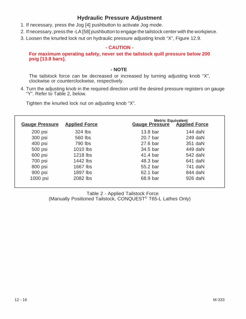
Hydraulic Pressure Adjustment1. If necessary, press the Jog [4] pushbutton to activate Jog mode.2. If necessary, press the -LA [58] pushbutton to engage the tailstock center with the workpiece.3. Loosen the knurled lock nut on hydraulic pressure adjusting knob “X”, Figure 12.9.
- CAUTION -For maximum operating safety, never set the tailstock quill pressure below 200psig [13.8 bars].
- NOTEThe tailstock force can be decreased or increased by turning adjusting knob “X”,clockwise or counterclockwise, respectively.
4. Turn the adjusting knob in the required direction until the desired pressure registers on gauge“Y”. Refer to Table 2, below.
Tighten the knurled lock nut on adjusting knob “X”.
12 - 16 M-333
Gauge Pressure Applied Force
13.8 bar 144 daN20.7 bar 249 daN27.6 bar 351 daN34.5 bar 449 daN41.4 bar 542 daN48.3 bar 641 daN55.2 bar 741 daN62.1 bar 844 daN68.9 bar 926 daN
Gauge Pressure Applied Force
200 psi 324 lbs300 psi 560 lbs400 psi 790 lbs500 psi 1010 lbs600 psi 1218 lbs700 psi 1442 lbs800 psi 1667 lbs900 psi 1897 lbs
1000 psi 2082 lbs
Metric Equivalent
Table 2 - Applied Tailstock Force(Manually Positioned Tailstock, CONQUEST© T65-L Lathes Only)

Quill LubricationFill the quill lubrication cavities with Mobiltemp® SHC 32 grease or equivalent military specification
Mobilgrease 28 at least once a month or every 160 hours of operation. Too much grease could dis-lodge the seal from the front of the tailstock casting or fill the rear keyway.
To lubricate the tailstock quill:
1. Move the turret away from the work space forthe tailstock.
2. Slide the tailstock away from the spindle, far tothe right, near the right side access door.
3. Power down the machine. Unlatch the right sideaccess door and lift it off.
4. Wipe clean grease fittings “F”, Figure 12.13,and the area around these fittings.
5. Use a grease gun to fill both quill lubricationcavities as follows:A. Align the grease gun nipple with the front
(closest to the tailstock nose, right side fit-ting in picture) grease fitting on thetailstock and put it on.
- NOTE -Know the approximate amount of grease pumped into the front cavity so that a likeamount can be added to the rear cavity.
B. Pump the grease into the lubrication cavity only until grease resistance is felt in thegrease gun handle and, then, stop pumping.Remember the approximate amount of grease added. Remove the grease gun nipplefrom the front fitting.
C. Align the grease gun nipple with the rear grease fitting and put it on.D. Pump a like amount of grease that was pumped into the front cavity into the rear cavity
and, then, stop pumping. Remove the grease gun nipple from the fitting.E. Check the seal between the front of the tailstock casting and the quill. If it has been
pushed out from its seat, wipe away excess grease and carefully slide the seal back intoits seat.
F. Wipe any excess grease from the fittings and seal area.6. Power up the machine.7. Extend and retract the quill several times to lubricate the quill.8. Position the tailstock; set the quill force.
M-333 12 - 17
Figure 12.13 - Quill LubricationGrease Fittings
TP3259.
F
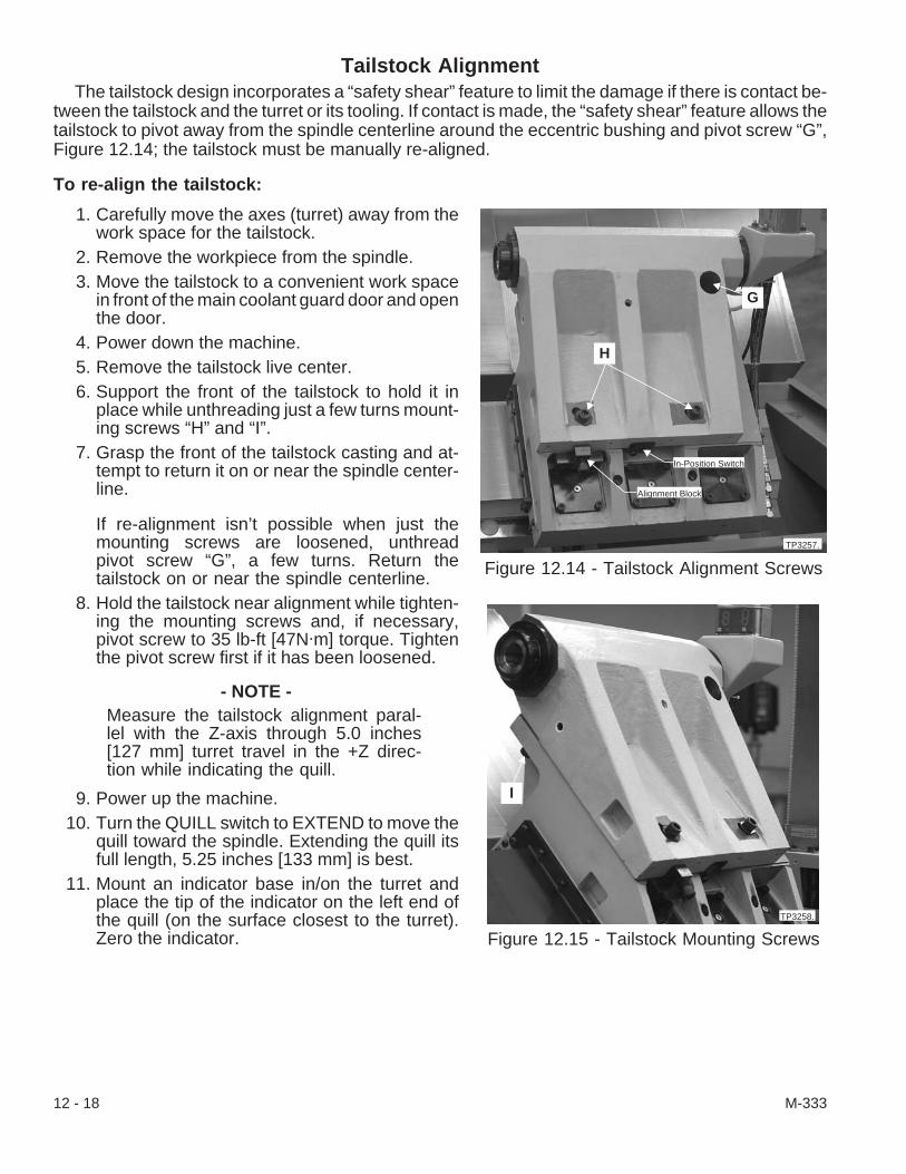
Tailstock AlignmentThe tailstock design incorporates a “safety shear” feature to limit the damage if there is contact be-
tween the tailstock and the turret or its tooling. If contact is made, the “safety shear” feature allows thetailstock to pivot away from the spindle centerline around the eccentric bushing and pivot screw “G”,Figure 12.14; the tailstock must be manually re-aligned.
To re-align the tailstock:
1. Carefully move the axes (turret) away from thework space for the tailstock.
2. Remove the workpiece from the spindle.3. Move the tailstock to a convenient work space
in front of the main coolant guard door and openthe door.
4. Power down the machine.5. Remove the tailstock live center.6. Support the front of the tailstock to hold it in
place while unthreading just a few turns mount-ing screws “H” and “I”.
7. Grasp the front of the tailstock casting and at-tempt to return it on or near the spindle center-line.
If re-alignment isn’t possible when just themounting screws are loosened, unthreadpivot screw “G”, a few turns. Return thetailstock on or near the spindle centerline.
8. Hold the tailstock near alignment while tighten-ing the mounting screws and, if necessary,pivot screw to 35 lb-ft [47N·m] torque. Tightenthe pivot screw first if it has been loosened.
- NOTE -Measure the tailstock alignment paral-lel with the Z-axis through 5.0 inches[127 mm] turret travel in the +Z direc-tion while indicating the quill.
9. Power up the machine.10. Turn the QUILL switch to EXTEND to move the
quill toward the spindle. Extending the quill itsfull length, 5.25 inches [133 mm] is best.
11. Mount an indicator base in/on the turret andplace the tip of the indicator on the left end ofthe quill (on the surface closest to the turret).Zero the indicator.
12 - 18 M-333
Figure 12.14 - Tailstock Alignment Screws
TP3257.
G
H
In-Position Switch
Alignment Block
Figure 12.15 - Tailstock Mounting Screws
I
TP3258.

- NOTE -The acceptable alignment specification is parallel within ±0.0008 inch [±0.0203mm] in 5.0 inches [127 mm].
12. Move the carriage (Z axis) 5.0 inches [127 mm] in the +Z direction, indicating along the quill. Ifthe tailstock is aligned within specification, tighten mounting screws “H” and “I” to 50 lb-ft [68N·m] torque. Also, tighten the pivot screw to this torque requirement first if it has been loose.
If the tailstock alignment is still out of specification, power down the machine and return tostep #6.
13. Return the tip of the indicator (-Z axis direction) to the left end of the quill.14. Check the alignment of the tailstock again as in step #12 above; however, this time, with the
tailstock aligned within specification, tighten the pivot screw to 65 lb-ft [88 N·m] torque and themounting screws to 80 lb-ft [108 N·m] torque. Each time the tailstock alignment is out of specifi-cation, power down the machine and return to step #6.
15. Repeat steps #13 and 14 until the tailstock is aligned within specification and the mountingscrews are tightened to 80 lb-ft [108 N·m] torque.
16. Position the tailstock; set the quill force and check the accuracy of several parts before continu-ing with parts machining or maintenance.
Tailstock Air LubricatorThe “air lift” feature unweights (separates) the tailstock from its dovetail way while lubricating the
tailstock carriage and dovetail way. This “air lifting” enables the tailstock to slide with less resistance.
Tailstock air lubricator “J”, Figure 12.16, is located on the air panel at the rear, left corner of the ma-chine.
To activate the “air lift”:
1. Press the Auxiliary Function [10] pushbutton to release the hydraulic clamping pressure on thetailstock and activate the “air lift” feature to allow the tailstock to be moved.
2. Slide the tailstock assembly to the desired loca-tion.
3. Press the Auxiliary Function [10] pushbuttonagain to de-activate the “air lift” feature and en-gage the hydraulic clamping pressure on thetailstock.
4. Check the position of the tailstock assembly bypressing the -LA [58] pushbutton to feed thetailstock center (quill) onto the workpiece.
Adjust the quill force as necessary.
M-333 12 - 19
Figure 12.16 - Tailstock Air Lubricator
TP3260.
JK
L

To add oil to the air lubricator:
The air lubricator makes certain that the air to the “air lift” has enough oil to protect the dovetail wayand bottom of the tailstock. Make certain that the air lubricator has oil.
NOTEFill air lubricator “J”, Figure 12.16, with Mobil DTE® 24 or Mist Lube® 24 oil.
The amount of oil used from the air lubricator is a function of usage or add the specified oil when oilin the bowl is low and/or if there is an alarm displayed on the CRT screen.
1. Unthread fill plug “K”, from the top of the air lubricator.2. Pour the specified oil into the air lubricator bowl. Thread on and tighten the fill plug.Another method of filling the tailstock “air lift” lubricator:
1. Press the latch down and turn the lubricator bowl one-eighth turn, enough to release the bowlfrom the lubricator head.
2. Fill the air lubricator bowl nearly to the top.3. Align the lubricator bowl on the lubricator head; lift up and twist the bowl until the latch engages.4. Pull down the lubricator bowl to test that the bowl is secure.If the tailstock air lubricator is ever replaced, mount an air gauge in line and install the oil level sen-
sor electrical cable on the bottom of the lubricator bowl; use a stop watch to adjust the lubricator to 1drop every 6 seconds at an air pressure of 15 psi. Adjust the oil screw on top of the lubricator head asnecessary to obtain the specified air lubrication. Set air flow control valve “L”, Figure 12.16, to 60 psi.[4.1 bars].
To set the “air lift” air pressure:
The “air lift” force from the air lubricator must be set to 60 psi. [4.1 bars] for proper dovetail way lubri-cation and tailstock movement.
1. If necessary, power down the machine.2. Mount an air gauge in line between air flow control valve “L”, Figure 12.16, and the air panel
manifold.3. Power up the machine.
- NOTEThe tailstock “air lift” force can be decreased or increased by turning the airvalve serrated adjusting knob clockwise or counterclockwise.
4. Loosen the lock nut on the valve adjusting knob. (Some air flow control valves may not have alock nut.)
5. Watch the air gauge while turning the adjusting knob in the required direction until the specifiedair pressure is met. If necessary, tighten the lock nut.
6. Power down the machine and disconnect the air gauge.7. Test the tailstock “air lift” as follows:
A. Power up the machine; press the Auxiliary Function [10] pushbutton to release the hy-draulic clamping pressure on the tailstock and activate the “air lift” feature to allow thetailstock to be moved.
B. Move the tailstock assembly on the dovetail way.
12 - 20 M-333

C. Press the Auxiliary Function [10] pushbutton to de-activate the “air lift” feature and en-gage the hydraulic clamping pressure on the tailstock.
D. Press the Auxiliary Function [10] pushbutton to release the hydraulic clamping pressureon the tailstock and finally move the tailstock to the desired location. Press thepushbutton again to de-activate the “air lift” feature.
8. Check the position of the tailstock assembly by pressing the -LA [58] pushbutton to extend thetailstock center (quill). This might also be a good time to lubricate the quill before machine opera-tion.
Adjust the quill force as necessary and continue with machine maintenance or operation.
- NOTES -
M-333 12 - 21

- NOTES -
12 - 22 M-333
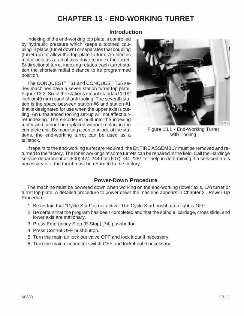
CHAPTER 13 - END-WORKING TURRET
IntroductionIndexing of the end-working top plate is controlled
by hydraulic pressure which keeps a toothed cou-pling in place (turret down) or separates that coupling(turret up) to allow the top plate to turn. An electricmotor acts as a radial axis drive to index the turret.Bi-directional turret indexing rotates each turret sta-tion the shortest radial distance to its programmedposition.
The CONQUEST® T51 and CONQUEST T65 se-ries machines have a seven station turret top plate,Figure 13.2. Six of the stations mount standard 1-1/2inch or 40 mm round shank tooling. The seventh sta-tion is the space between station #6 and station #1that is designated for use when the upper axis is cut-ting. An unbalanced tooling set-up will not affect tur-ret indexing. The encoder is built into the indexingmotor and cannot be replaced without replacing thecomplete unit. By mounting a center in one of the sta-tions, the end-working turret can be used as atailstock.
If repairs to the end-working turret are required, the ENTIRE ASSEMBLY must be removed and re-turned to the factory. The inner workings of some turrets can be repaired in the field. Call the Hardingeservice department at (800) 424-2440 or (607) 734-2281 for help in determining if a serviceman isnecessary or if the turret must be returned to the factory.
Power-Down ProcedureThe machine must be powered down when working on the end-working (lower axis, LA) turret or
turret top plate. A detailed procedure to power down the machine appears in Chapter 2 - Power-UpProcedure.
1. Be certain that “Cycle Start” is not active. The Cycle Start pushbutton light is OFF.2. Be certain that the program has been completed and that the spindle, carriage, cross slide, and
lower axis are stationary.3. Press Emergency Stop (E-Stop) [74] pushbutton.4. Press Control OFF pushbutton.5. Turn the main air lock out valve OFF and lock it out if necessary.6. Turn the main disconnect switch OFF and lock it out if necessary.
M-333 13 - 1
Figure 13.1 - End-Working Turretwith Tooling
TP84.
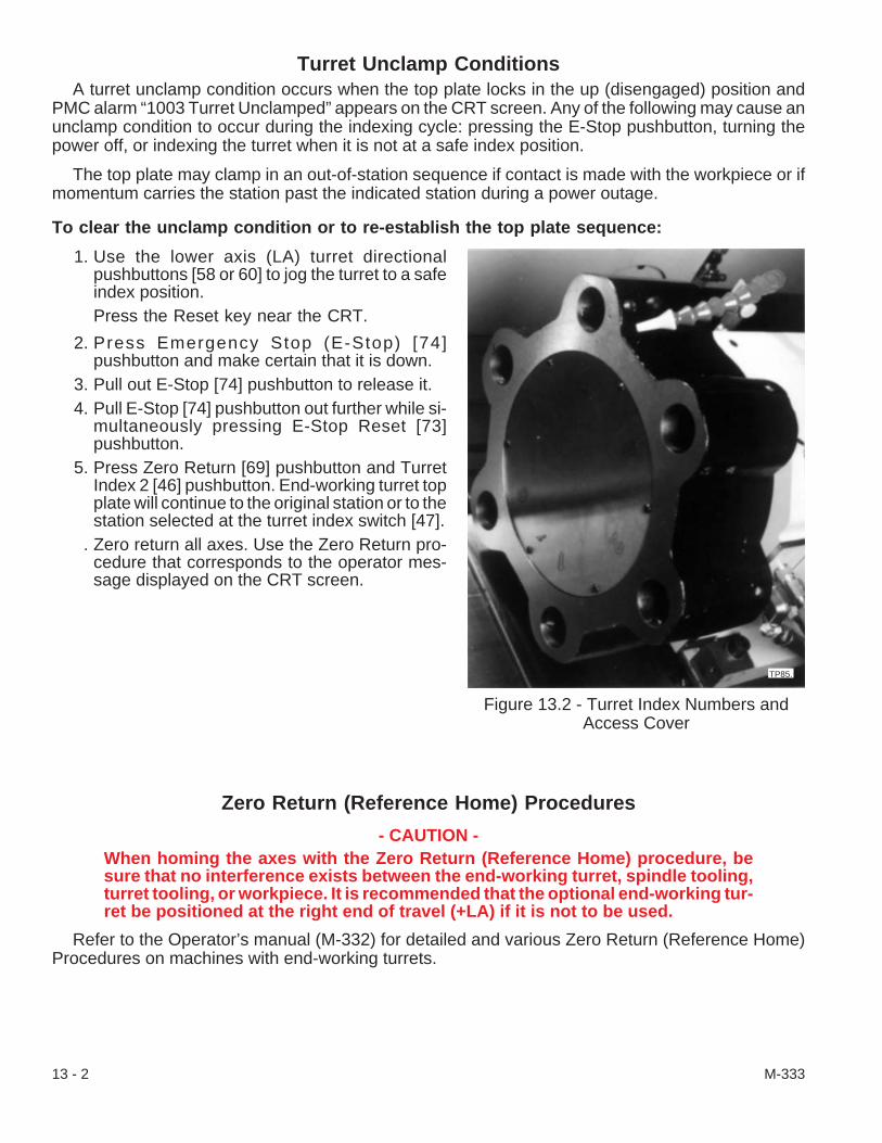
Turret Unclamp ConditionsA turret unclamp condition occurs when the top plate locks in the up (disengaged) position and
PMC alarm “1003 Turret Unclamped” appears on the CRT screen. Any of the following may cause anunclamp condition to occur during the indexing cycle: pressing the E-Stop pushbutton, turning thepower off, or indexing the turret when it is not at a safe index position.
The top plate may clamp in an out-of-station sequence if contact is made with the workpiece or ifmomentum carries the station past the indicated station during a power outage.
To clear the unclamp condition or to re-establish the top plate sequence:
1. Use the lower axis (LA) turret directionalpushbuttons [58 or 60] to jog the turret to a safeindex position.Press the Reset key near the CRT.
2. Press Emergency Stop (E-Stop) [74]pushbutton and make certain that it is down.
3. Pull out E-Stop [74] pushbutton to release it.4. Pull E-Stop [74] pushbutton out further while si-
multaneously pressing E-Stop Reset [73]pushbutton.
5. Press Zero Return [69] pushbutton and TurretIndex 2 [46] pushbutton. End-working turret topplate will continue to the original station or to thestation selected at the turret index switch [47].
. Zero return all axes. Use the Zero Return pro-cedure that corresponds to the operator mes-sage displayed on the CRT screen.
Zero Return (Reference Home) Procedures
- CAUTION -When homing the axes with the Zero Return (Reference Home) procedure, besure that no interference exists between the end-working turret, spindle tooling,turret tooling, or workpiece. It is recommended that the optional end-working tur-ret be positioned at the right end of travel (+LA) if it is not to be used.
Refer to the Operator’s manual (M-332) for detailed and various Zero Return (Reference Home)Procedures on machines with end-working turrets.
13 - 2 M-333
Figure 13.2 - Turret Index Numbers andAccess Cover
TP85.
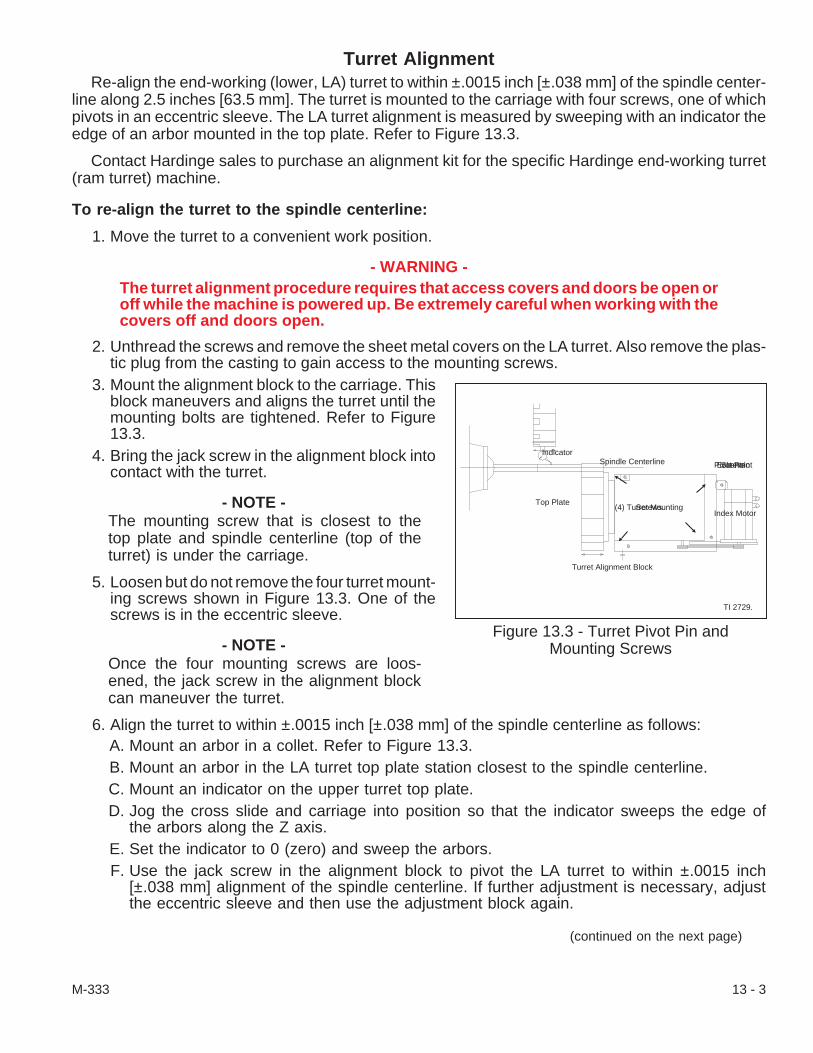
Turret AlignmentRe-align the end-working (lower, LA) turret to within ±.0015 inch [±.038 mm] of the spindle center-
line along 2.5 inches [63.5 mm]. The turret is mounted to the carriage with four screws, one of whichpivots in an eccentric sleeve. The LA turret alignment is measured by sweeping with an indicator theedge of an arbor mounted in the top plate. Refer to Figure 13.3.
Contact Hardinge sales to purchase an alignment kit for the specific Hardinge end-working turret(ram turret) machine.
To re-align the turret to the spindle centerline:
1. Move the turret to a convenient work position.
- WARNING -The turret alignment procedure requires that access covers and doors be open oroff while the machine is powered up. Be extremely careful when working with thecovers off and doors open.
2. Unthread the screws and remove the sheet metal covers on the LA turret. Also remove the plas-tic plug from the casting to gain access to the mounting screws.
3. Mount the alignment block to the carriage. Thisblock maneuvers and aligns the turret until themounting bolts are tightened. Refer to Figure13.3.
4. Bring the jack screw in the alignment block intocontact with the turret.
- NOTE -The mounting screw that is closest to thetop plate and spindle centerline (top of theturret) is under the carriage.
5. Loosen but do not remove the four turret mount-ing screws shown in Figure 13.3. One of thescrews is in the eccentric sleeve.
- NOTE -Once the four mounting screws are loos-ened, the jack screw in the alignment blockcan maneuver the turret.
6. Align the turret to within ±.0015 inch [±.038 mm] of the spindle centerline as follows:A. Mount an arbor in a collet. Refer to Figure 13.3.B. Mount an arbor in the LA turret top plate station closest to the spindle centerline.C. Mount an indicator on the upper turret top plate.D. Jog the cross slide and carriage into position so that the indicator sweeps the edge of
the arbors along the Z axis.E. Set the indicator to 0 (zero) and sweep the arbors.F. Use the jack screw in the alignment block to pivot the LA turret to within ±.0015 inch
[±.038 mm] alignment of the spindle centerline. If further adjustment is necessary, adjustthe eccentric sleeve and then use the adjustment block again.
(continued on the next page)
M-333 13 - 3
Figure 13.3 - Turret Pivot Pin andMounting Screws
Pivot PointEccentricSleeve
Index MotorTop Plate
Spindle Centerline
(4) Turret MountingScrews
Turret Alignment Block
TI 2729.
Indicator

7. Tighten the four turret mounting screws. Secure the eccentric sleeve and tighten the screw to 50lb-ft [68 N•m] torque. Tighten the two lower mounting screws and the screw under the carriage to82 lb-ft [111 N•m].
8. Sweep the edge of the top plate once again to verify that the LA turret alignment is within thespecification. If the turret is not in alignment, loosen the mounting screws and repeat steps #6and #7 until it is aligned.
- CAUTION -Do not machine stock until the plug, access covers, and doors are in place andfastened.
9. Mount the sheet metal covers on the LA turret in place.10. Unthread the screws and remove the alignment block from the carriage.11. Close the main access door.12. Home the axes and LA turret.
Index Motor Drive BeltThe index motor drive belt connects the index motor to the turret pulley for the end-working turret. It
is adjusted by moving the index motor plate toward or away from the turret.
To adjust/replace the index motor:
1. Home the turret near the rear access door.2. Power down the machine.3. Use the key and unlatch the Z compartment ac-
cess door in two places. Lift the door off.4. Unthread the screws and remove the cover
over the index motor and turret pulley.
- NOTE -Belt tension should be .10 inches [2.54mm] deflection at 1.5 to 2 pounds [6.7to 8.9 N] of force applied at a pointmidway between the pulleys.
5. If the drive belt needs to be adjusted, loosenfour screws that mount motor plate “A”, Figure13.4, to the turret. Slide the motor plate towardthe turret to remove tension from the belt oraway from the turret to increase the belt ten-sion. Tighten the motor plate screws to 30 lb-ft[41 N•m] torque.If the belt is to be replaced, loosen the four screws that mount the motor plate to the turretand slide the motor plate toward the turret to remove tension from the belt. Remove andreplace the belt on the pulleys. Align the belt on the pulleys and put tension on the belt bymoving the motor plate away from the turret. Tighten the motor plate screws to 30 lb-ft [41N•m] torque.
6. Mount the index motor and turret pulley cover and tighten the screws.7. Install the Z compartment access door.8. Power up the machine and check the lower axis top plate index.
13 - 4 M-333
Figure 13.4 - Turret Index Motor
A
B
C
DTP86.

LA Turret Clamp/Unclamp (26PRS) Proximity SwitchThe lower (LA) turret clamp/unclamp switch is located on a bracket within the turret. It is activated
by “reading” the turret index plate when the top plate is clamped.
To replace and adjust the switch:
1. Move the LA turret to a convenient work position in front of the coolant/chip guard door.2. Power down the machine.3. Open the coolant/chip door to gain entrance to the LA turret. Unthread the screws and remove
the cover over the index motor and turret pulley.4. Unthread the screws and take cover “E”, Figure
13.6, off to gain access to the switch bracketand switch.
5. Unthread the screws and remove the proximityswitch bracket with the switch.
6. Use the bracket as reference when measuringthe distance from the bracket to the tip of theswitch for approximate switch replacement lo-cation.
7. Carefully unthread the nuts and remove theswitch from the bracket.
- NOTE -The switch bracket has slots to set thefinal switch adjustment.
8. Install the switch on the bracket and adjust theswitch depth per step #6. Use both lock wash-ers on the switch and tighten the switch nuts to60 lb-in. [6.8 N•m] torque.
9. Remount the bracket loosely in the turret.10. Push the bracket up toward turret shim thick-
ness number and set the switch per Figure 13.5and as follows:A. Turret unclamp/clamp switch at .030 inch
[.76 mm].B. Tighten the bracket screws to 60 lb-in.
[6.8 N•m] torque.11. Check the distance between the turret index
plate and the switch per step #10. Adjust the fi-nal switch setting as necessary.
(continued on the next page)
M-333 13 - 5
Figure 13.5 - Proximity Switch Settings
26PRSTurret Unclamp/Clamp Switch
0.030 Inch [.76 mm]
Turret Index Plate
TI2730A
Figure 13.6 - Proximity SwitchAccess Cover
E
TP87.

12. Connect the wire(s) for the new switch as follows:A. On top of the machine, behind the control panel, unthread the screws and remove the
vent screen for access to the cables coming from through the Goretube® Flex hose.B. Use the key and unlatch the control case door in two places. Open the door.C. Unthread the screws and loosen the Goretube Flex hose junction box from the LA turret.D. Trace the switch cable from the old switch through the Goretube flex hose and into the
control case. Trace it to the terminals.E. Record the switch wire connections so that the correct connections are made during re-
placement.F. Disconnect the wires from the terminal block connections.G. Fasten a line to the switch cable and lead it through the cable route back to the turret.H. Unthread the knurled nut from the electrical fitting and loosen the grommet. Unfasten
the line from the cable and remove the old switch and cable.I. Feed the cable from the new switch through the electrical fitting, grommet, and knurled
nut. Fasten the line to the new cable, put the grommet in place, and tighten the knurlednut.
J. Use the line and carefully route the cable through the machine into the control case.K. Connect the wires to the terminal block connections per step E, above.
13. Place cover “E”, Figure 13.6, on the LA turret and fasten it with its screws.14. Power up the machine.15. Test the LA turret top plate unclamp/clamp (up/down) motion as follows:
- NOTES -The Turret Station switch [47] must be on a number - not 0 or past 12/10.
Continuously change the station switch number each time the top plate needs tounclamp and clamp.
A. Press the Zero Return [69] and Turret Index 2 [46] pushbuttons; the top plate will un-clamp, index to the selected station, and clamp.
B. Turn the turret station switch [47] to the number of the station desired - usually stationnumber 1.
C. Again, press and hold the Zero Return [69] pushbutton while pressing the Turret Index 2[46] pushbutton to unclamp (raise) the top plate, index to the selected number andclamp.
16. Test the turret top plate station select by repeating step #15 and comparing the turret stationnumber with the number selected.
13 - 6 M-333
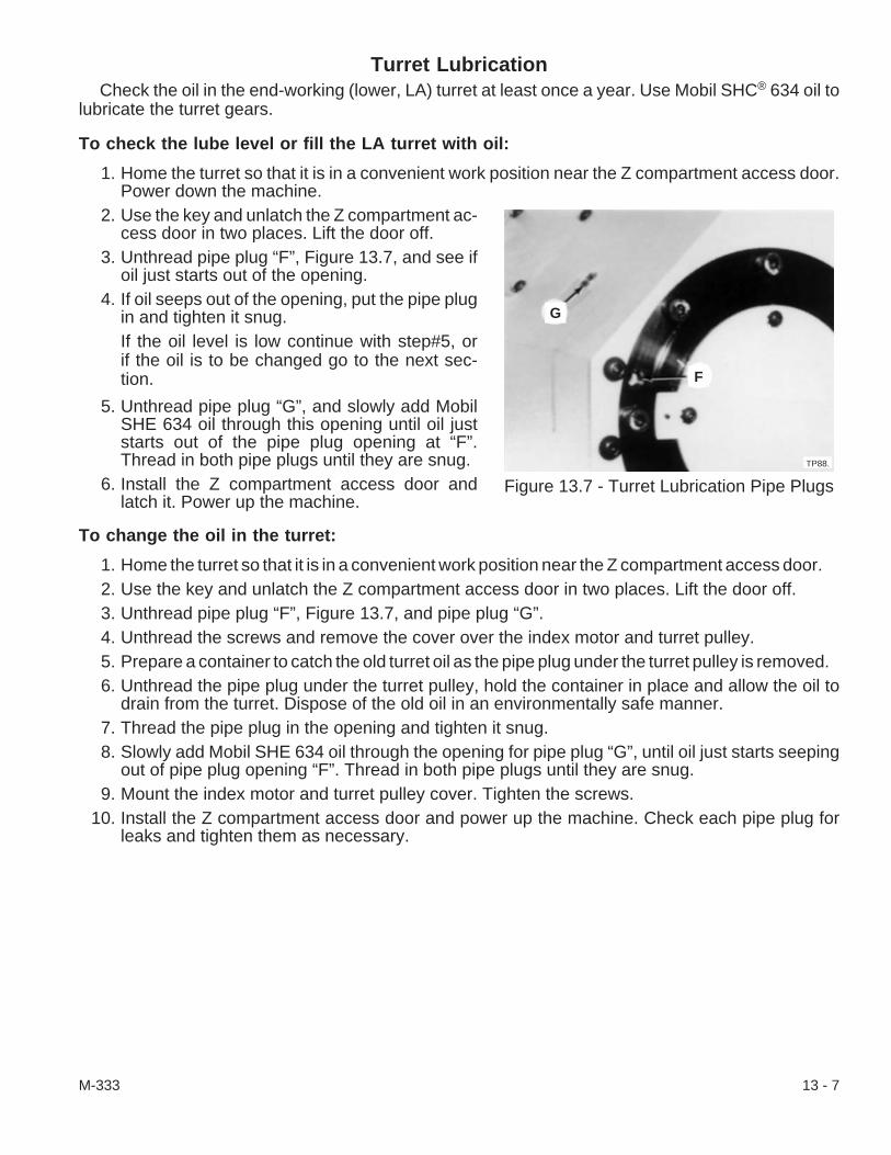
Turret LubricationCheck the oil in the end-working (lower, LA) turret at least once a year. Use Mobil SHC® 634 oil to
lubricate the turret gears.
To check the lube level or fill the LA turret with oil:
1. Home the turret so that it is in a convenient work position near the Z compartment access door.Power down the machine.
2. Use the key and unlatch the Z compartment ac-cess door in two places. Lift the door off.
3. Unthread pipe plug “F”, Figure 13.7, and see ifoil just starts out of the opening.
4. If oil seeps out of the opening, put the pipe plugin and tighten it snug.If the oil level is low continue with step#5, orif the oil is to be changed go to the next sec-tion.
5. Unthread pipe plug “G”, and slowly add MobilSHE 634 oil through this opening until oil juststarts out of the pipe plug opening at “F”.Thread in both pipe plugs until they are snug.
6. Install the Z compartment access door andlatch it. Power up the machine.
To change the oil in the turret:
1. Home the turret so that it is in a convenient work position near the Z compartment access door.2. Use the key and unlatch the Z compartment access door in two places. Lift the door off.3. Unthread pipe plug “F”, Figure 13.7, and pipe plug “G”.4. Unthread the screws and remove the cover over the index motor and turret pulley.5. Prepare a container to catch the old turret oil as the pipe plug under the turret pulley is removed.6. Unthread the pipe plug under the turret pulley, hold the container in place and allow the oil to
drain from the turret. Dispose of the old oil in an environmentally safe manner.7. Thread the pipe plug in the opening and tighten it snug.8. Slowly add Mobil SHE 634 oil through the opening for pipe plug “G”, until oil just starts seeping
out of pipe plug opening “F”. Thread in both pipe plugs until they are snug.9. Mount the index motor and turret pulley cover. Tighten the screws.
10. Install the Z compartment access door and power up the machine. Check each pipe plug forleaks and tighten them as necessary.
M-333 13 - 7
Figure 13.7 - Turret Lubrication Pipe Plugs
G
F
TP88.

- NOTES -
13 - 8 M-333

CHAPTER 14 - SUB-SPINDLE
IntroductionThe sub-spindle option on the CONQUEST® T51, CONQUEST T51SP, CONQUEST T51 “Big
Bore”, and CONQUEST T65 CNC Bar and Chucker machines is available as original equipment only.The spindle has the standard 16C spindle and will accept a center head (Hardinge part numberAK-0000296-16 C) so that the sub-spindle can act as a tailstock. The travel limit, Figure 14.1, is mea-sured from the face of the main spindle to the face of the sub-spindle. Maintenance of the sub-spindlebase, hydraulic cylinder, limit switches, and hydraulic module is supplemented by information inChapter 12 - Tailstock and Chapter 5 - Hydraulic Module.
Refer to “Chapter 15 - Sub-Spindle (Hydraulic Axis Drive)(Option)” or “Chapter 16 - Sub-Spindle”(Ball Screw Axis Drive)(Option)” in Operator’s Manual (M-332) or “Chapter 15 - Sub-Spindle (Op-tion)(Hydraulic Axis Drive)” or “Chapter 16 - Sub-Spindle (Option)(Ball Screw Axis Drive)” in Program-mer’s Manual (M-331) for instructions to activate and de-activate the sub-spindle option. The zeroreturn (HOME) procedures are explained in Chapter 2 in this manual.
OverviewThe sub-spindle rides on linear carriage ways. A “safety shear” feature in the design minimizes
damage to tooling and linear ways if there is contact between the turret and sub-spindle.
Sub-spindle travel toward or away from the main spindle is provided by a hydraulic cylinder or a ballscrew, depending on the option, and is controlled either by programmed commands or manually fromthe control panel. The travel is measured from the Home (retract) position to the forward (extend) po-sition. For hydraulic driven sub-spindles, the rapid-to-feed dog should be adjusted from .50 inch [12.7mm] to .75 inch [19.05 mm] before contact with the workpiece to slow the feed of the sub-spindle. Theforward solid stop position should be set at approximately .12 inch [3.18 mm] after the expected con-tact with the piece. Positioning of sub spindles on machines with this option is controlled by program-ming Y axis commands.
The sub-spindle casting is shimmed in place on the base for sub-spindle headstock alignment withthe main spindle in the Y direction. An eccentric bushing assembly is adjusted to position thesub-spindle headstock in the X direction.
OperationFor hydraulic driven sub-spindles, force against the workpiece is controlled by hydraulic pressure
which is regulated by knob “B”, Figure 14.5, on the left side of the hydraulic manifold. It is recom-mended that the linear force not be adjusted below 200 psi [13.8 bars], refer to Table 14.1. Gauge “C”indicates hydraulic pressure in pounds per square inch from 0 through 1000 [0 through 69 bars]. Ad-justment and replacement of hydraulic system components pertinent to the maintenance of thesub-spindle are detailed in Chapter 5 - Hydraulic Module; however, some components, such as speedvalve “B” and solenoid valve “D”, are identified in Figure 14.5. A hydraulic cylinder purge system,which is an additional manifold, valve, and hose assembly, stabilizes the sub-spindle position duringchucking.
The sub-spindle collet closer holding force of hydraulically driven sub-spindles is controlled by aseparate set of solenoid valves “B”, gauge “C”, and a knob located behind auxiliary (sub-spindle) hy-draulic manifold. The collet closer holding force of ball screw driven sub-spindles is set by adjustingknob “D” while reading gauge “E” on the main manifold. There is no auxiliary hydraulic manifold on theball screw driven sub-spindle hydraulic system.
M-333 14 - 1

Forward and backward motion of the sub-spindle assembly is supplied either by the machine’s hy-draulic system or by a motor driven ball screw. When a programmed M84 (Sub-Spindle Forward)command is executed in Auto, MDI, or Single mode or when the -LA pushbutton is pressed in Jogmode, the sub-spindle assembly moves toward the main spindle. Execution of an M85 (Sub-SpindleRetract) command in Auto, MDI, or Single mode or pressing the +LA pushbutton in Jog mode causesthe assembly to move to the Home position.
- NOTE -The sub-spindle can only be moved toward the main spindle at the rapid traverserate when the machine is in AUTO or MDI mode and with the main coolant guarddoor closed.
There are two rates of motion:
1. The rapid traverse rate (approximately 300 ipm [7620 mm/min]).2. The adjustable feed rate. Refer to the Operator’s Manual (M-332) for information on setting the
adjustable feedrate.
Main Guard Door Safety InterlockCONQUEST® T51 and T65 machines equipped with the sub-spindle option, incorporate a safety
interlock feature which does not allow the main coolant guard door to be opened after the machinetool’s electric power is off.
The purpose of this safety interlock is to prevent potential personal injury in the event of a powerfailure. The sub-spindle is not equipped with an external brake. If a power failure occurs, the sub-spin-dle coasts to a stop rather than stopping immediately.
14 - 2 M-333
Figure 14.1 - Hydraulic Cylinder Driven Sub-SpindleTravel Specifications
TI2708
CL
25.00 [635.0] Home Position24.75 [628.65]
3.000 [76.20] Forward Position2.75 [69.85]
Sub-SpindleForward(Extend)
Sub-Spindleat Home(Retract)
4.25 [108.0]4.50 [114.3]
MainSpindle
Headwall
NOTES: Dimensions are inch [millimeter]
Conquest T51/T51SP dimensions overConquest T51w/Big Bore - T65 dimension
Length of stroke is 22 [558.8]
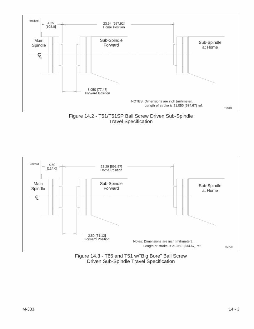
M-333 14 - 3
Figure 14.2 - T51/T51SP Ball Screw Driven Sub-SpindleTravel Specification
TI2708
CL
23.54 [597.92]Home Position
3.050 [77.47]Forward Position
Sub-SpindleForward
Sub-Spindleat Home
4.25[108.0]
NOTES: Dimensions are inch [millimeter].
MainSpindle
Headwall
Length of stroke is 21.050 [534.67] ref.
Figure 14.3 - T65 and T51 w/"Big Bore" Ball ScrewDriven Sub-Spindle Travel Specification
TI2708
CL
23.29 [591.57]Home Position
2.80 [71.12]Forward Position
Sub-SpindleForward
Sub-Spindleat Home
4.50[114.0]
Notes: Dimensions are inch [millimeter].
MainSpindle
Length of stroke is 21.050 [534.67] ref.
Headwall

Free SpindleA “Free Spindle” condition allows the sub-spindle to be turned by hand. The sub-spindle is in a
“Free Spindle” condition whenever it is not being driven by the sub-spindle motor. Whenever possible,workholding devices mounted in the sub-spindle should be plugged to prevent chip buildup in thesub-spindle draw tube.
- CAUTION -Manual lock pin “A”, Figure 14.2, isNOT interlocked with the machinecontrol. DO NOT attempt to rotatethe sub-spindle while this lock pinis engaged.
Hydraulic Force Against WorkpieceOn hydraulic cylinder driven sub-spindles, force
against the workpiece is controlled by hydraulic pres-sure which is regulated by knob “B”, Figure 15.5, onthe left side of the main hydraulic manifold. It is rec-ommended that the linear force not be adjusted be-low 200 psi [13.8 bars], refer to Table 14.1. Gauge“C” indicates hydraulic pressure in pounds persquare inch from 0 through 1000 and in bars from 0through 69. Adjustment and replacement of hydrau-lic system components pertinent to the maintenanceof the sub-spindle are detailed in Chapter 5 - Hydrau-lic Module. A hydraulic cylinder purge system, whichis an additional manifold, valve, and hose assembly,stabilizes the sub-spindle position during chucking.
The sub-spindle collet closer holding force is con-trolled by a separate set of solenoid valves and agauge.
14 - 4 M-333
Figure 14.4 - Sub-Spindle Manual Lock Pin
TP1032.
A
Figure 14.5 - Hydraulic Manifold
D
EB C
TI2826.
Gauge Pressure Applied Force
13.8 bar 130 daN20.7 bar 195 daN27.6 bar 265 daN34.5 bar 345 daN41.4 bar 410 daN48.3 bar 490 daN
Gauge Pressure Applied Force
200 psi 290 lbs300 psi 440 lbs400 psi 600 lbs500 psi 775 lbs600 psi 925 lbs700 psi 1100 lbs
Metric Equivalent
Table 14.1 - Applied Sub-Spindle Force

Sub-Spindle Collet CloserThe sub-spindle is equipped with a .50 inch [12.7 mm] stroke, hydraulically-actuated collet closer. If
repairs to the collet closer assembly are required, the entire assembly must be removed and returnedto the factory.
- CAUTION -DO NOT exceed the maximum pressure setting, as shown in Table 14.2.
- NOTES -The sub-spindle collet closer has an operational pressure range of 60 to 500 psi[4.14 to 34.5 bars].
It is the responsibility of the machine operator or set-up person to properly adjustthe collet closer’s hydraulic pressure, based on the type of material to be machinedand the configuration of the workpiece.
The sub-spindle collet closer chucking force is controlled by hydraulic oil pressure. Sub-spindlecollet closer pressure adjustment knob “D”, Figure 14.5, located on the top of the manifold. Gauge “E”registers the collet closer hydraulic pressure in psi and bars. Refer to Table 15.2, below to determinethe approximate gripping force that will be applied to the workpiece for a given pressure. A checkvalve system positively holds the closer open or closed, whichever is active, in the event of hydraulicpressure failure.
Basic Machine Power-Down ProcedureThe power-down procedure is a systematic method of safely turning off the control and readying
the machine for maintenance. The machine must be powered down when working on the sub-spindle(lower axis, LA) or any of its components. A detailed procedure to power down the machine appearsin Chapter 2 - Power-Up Procedure in this manual.
1. Be certain that “Cycle Start” is not active. The CYCLE START [72] pushbutton light is OFF.2. Be certain that the program has been completed and that the spindle, carriage, cross slide, and
lower axis are stationary.3. Press the Emergency Stop (E-Stop) [74] pushbutton.4. Press CONTROL OFF pushbutton.5. Turn the main air lock out valve OFF and lock it if necessary.6. Turn the main disconnect switch OFF and lock it if necessary.
M-333 14 - 5
Table 14.2 - Sub-Spindle Collet Closer Chucking Force
Gauge Pressure Chucking Force
6.9 bar 538 daN13.8 bar 1076 daN20.7 bar 1615 daN27.6 bar 2152 daN34.5 bar 2678 daN
Gauge Pressure Chucking Force
100 psi 1206 lbs200 psi 2412 lbs300 psi 3619 lbs400 psi 4826 lbs500 psi 6000 lbs
Metric Equivalent

Alignment
- WARNING -The sub-spindle alignment procedures require that access covers, doors, andright coolant guard panel be open or off while the machine is powered up. Be ex-tremely careful when working with the covers off and doors open.
- NOTE -Special alignment kit for machines with standard main spindle CL-0012101-20C1or machines with “big bore” main spindle CL-0012101-25C1 are required toproperly align the sub-spindle with the main spindle. Contact the Hardinge Sales topurchase a kit or call Hardinge Service Department at (800) 424-2440 or (607)734-2281 to arrange for a service man and kit.
The hydraulic cylinder driven sub-spindle has a different alignment procedure than the ball screwdriven sub-spindle. The carriage is a special design and torque specifications are different. Use thealignment procedure according to the design of the machine.
In either case, the sub-spindle casting moves around a pivot assembly on the carriage when theturret or its tools make contact with it. One sign that contact has occurred between the X-axis andsub-spindle is that the X-axis torque limiter has tripped and the control is in an Emergency Stop(E-Stop) condition. Another sign that the sub-spindle is out of alignment is that workpieces made withthe sub-spindle are out of specification.
To re-align the hydraulic cylinder driven sub-spindle:
1. Bring the control out of E-Stop; jog the turret upand away from the sub-spindle. Open the maincoolant guard door.
- NOTE -It may be necessary to remove thecoolant guard panel (to the right of thedoor opening, the coolant canopy) foreasier access to the sub-spindle. If ithas to be removed, unthread the nutsalong the bottom lip, unthread thescrews along the top and side, and liftthe panel from the machine.
2. Unthread the screws and remove the accesscover along the sub-spindle base and the ac-cess cover on top near the rear of the sub-spin-dle.
3. Make certain that the control is out of E-Stop; jog the sub-spindle to a convenient work position.The sub-spindle should be away from any workpiece in the main spindle but near the opening ofthe main door.
4. Power down the machine. Lock out (disable) the main disconnect switch by pulling the main dis-connect switch center tab out and placing a lock through it.
5. Unthread two screws from the base cover (near the left “F” in Figure 14.6) and mount the adjust-ing block (CSB-0011320-02) to both hold and align the sub-spindle.
6. Loosen the mounting screws only enough to pivot the sub-spindle into place. Two mountingscrews “F’, require a hex socket wrench and one mounting screw up under the base below thesub-spindle nose requires the adapter wrench from the kit.
14 - 6 M-333
Figure 14.6 - Hydraulic ActuatedSub-Spindle Mounting Screws
FF
TP1034
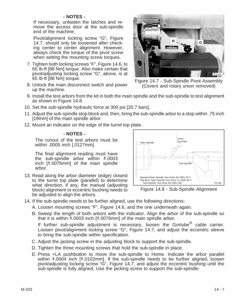
- NOTES -If necessary, unfasten the latches and re-move the access door at the sub-spindleend of the machine.Pivot/alignment locking screw “G”, Figure14.7, should only be loosened after check-ing center to center alignment. However,always check the torque of the pivot screwwhen setting the mounting screw torques.
7. Tighten both locking screws “F”, Figure 14.6, to65 Ib-ft [88 Nm] torque. Also make certain thatpivot/adjusting locking screw “G”, above, is at65 Ib-ft [88 Nm] torque.
8. Unlock the main disconnect switch and powerup the machine.
9. Install the test arbors from the kit in both the main spindle and the sub-spindle to test alignmentas shown in Figure 14.8.
10. Set the sub-spindle hydraulic force at 300 psi [20.7 bars].11. Adjust the sub-spindle stop block and, then, bring the sub-spindle arbor to a stop within .75 inch
[19mm] of the main spindle arbor.12. Mount an indicator on the edge of the turret top plate.
- NOTES -The runout of the test arbors must bewithin .0005 inch [.0127mm].
The final alignment reading must havethe sub-spindle arbor within ±.0003inch [±.0076mm] of the main spindlearbor.
13. Read along the arbor diameter (edge) closestto the turret top plate (parallel) to determinewhat direction, if any, the manual (adjustingblock) alignment or eccentric bushing needs tobe adjusted to align the arbors.
14. If the sub-spindle needs to be further aligned, use the following directions:A. Loosen mounting screws “F”, Figure 14.6, and the one underneath again.B. Sweep the length of both arbors with the indicator. Align the arbor of the sub-spindle so
that it is within ±.0003 inch [±.0076mm] of the main spindle arbor.If further sub-spindle adjustment is necessary, loosen the Gortube® cable carrier.Loosen pivot/alignment locking screw “G”, Figure 14.7, and adjust the eccentric sleeveto bring the sub-spindle within specification.
C. Adjust the jacking screw in the adjusting block to support the sub-spindle.D. Tighten the three mounting screws that hold the sub-spindle in place.E. Press +LA pushbutton to move the sub-spindle to Home. Indicate the arbor parallel
within ±.0004 inch [±.0102mm]. If the sub-spindle needs to be further aligned, loosenpivot/adjusting locking screw “G”, Figure 14.7, and adjust the eccentric bushing until thesub-spindle is fully aligned. Use the jacking screw to support the sub-spindle.
M-333 14 - 7
Figure 14.7 - Sub-Spindle Pivot Assembly(Covers and rotary union removed)
TP1035.
H G
Figure 14.8 - Sub-Spindle Alignment
TI1735.
Sub-Spindle
TurretTop PlateMain Spindle
Standard Main Spindle Test Arbor AK-2691-20 C“Big-Bore” Main Spindle Test Arbor CL-2690-25 C
Sub-Spindle Test Arbor AK-2691-16C

15. Torque the three mounting screws to 65 Ib-ft [88 Nm] force and make certain that pivot adjustinglocking screw “G”, is at 65 Ib-ft [88 Nm].
16. Check the alignment of the arbors again and make adjustments as necessary. Finally, leavepivot/adjusting locking screw torque alone but tighten the other three mounting screws to 80 Ib-ft[108 Nm].
17. Unthread the screws and remove the adjusting block. Install the two base cover screws.18. Mount all the sub-spindle covers, right coolant guard panel, and access covers. Then, power up
the machine.
To re-align the ball screw driven sub-spindle:
The alignment of the ball screw driven sub-spindle must be checked if the X-axis torque limiter hasbeen tripped or if workpiece parts held in the sub-spindle are out of specification. Re-align the ballscrew driven sub-spindle (lower axis, LA) parallel within ±.0005 inch [±.0127mm] to the main spindlecenterline. Read the Alignment introduction, page 14-6, and refer to Figure 14.8.
1. Make certain that the control is out of E-Stop; jog the turret up and away from the sub-spindle.Then, move the sub-spindle to a work position near the spindle and the main access door open-ing.
- NOTE -It may be necessary to remove the coolant guard panel (to the right of the dooropening, the coolant canopy) for easier access to the sub-spindle. If it has to beremoved, unthread the nuts along the bottom lip, unthread the screws along thetop and side, and lift the panel from the machine.
2. Unthread the screws and remove the access cover along the sub-spindle base and the accesscover on top near the rear of the sub-spindle.
3. Mount adjusting block (CSB-0011320-02) from the kit in two threaded holes just below leftmounting screw “I” in Figure 14.9. The block holds and maneuvers the sub-spindle.
- NOTE -Two mounting screws “I”, require asocket wrench but the mounting screwup under the base below the sub-spin-dle nose requires the adapter wrenchfrom the kit.
4. Loosen the three sub-spindle mounting screwsonly enough to pivot the sub-spindle into place.The sub-spindle may align near specificationwithout loosening locking screw “G”, Figure14.7, in the pivot/alignment assembly.
14 - 8 M-333
Figure 14.9 - Ball Screw Driven
TP1029.
I I
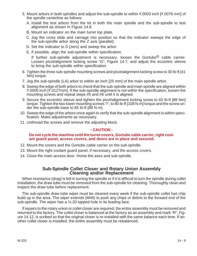
5. Mount arbors in both spindles and adjust the sub-spindle to within ±.0003 inch [±.0076 mm] ofthe spindle centerline as follows:A. Install the test arbors from the kit in both the main spindle and the sub-spindle to test
alignment as shown in Figure 14.8.B. Mount an indicator on the main turret top plate.C. Jog the cross slide and carriage into position so that the indicator sweeps the edge of
the sub-spindle arbor along the Z axis (parallel).D. Set the indicator to 0 (zero) and sweep the arbor.E. If possible, align the sub-spindle within specification.
If further sub-spindle adjustment is necessary, loosen the Gortube® cable carrier.Loosen pivot/alignment locking screw “G”, Figure 14.7, and adjust the eccentric sleeveto bring the sub-spindle within specification.
6. Tighten the three sub-spindle mounting screws and pivot/alignment locking screw to 30 Ib-ft [41Nm] torque.
7. Jog the sub-spindle (LA) arbor to within an inch [25 mm] of the main spindle arbor.8. Sweep the edge of both arbors to check that the sub-spindle and main spindle are aligned within
±.0005 inch [±.0127mm]. If the sub-spindle alignment is not within the specification, loosen themounting screws and repeat steps #5 and #6 until it is aligned.
9. Secure the eccentric sleeve and tighten the pivot/alignment locking screw to 65 Ib-ft [88 Nm]torque. Tighten the two lower mounting screws “I”, to 80 Ib-ft [108 N-m] torque and the screw un-der the sub-spindle base to 65 Ib-ft [88 N-m].
10. Sweep the edge of the arbors once again to verify that the sub-spindle alignment is within speci-fication. Make adjustments as necessary.
11. Unthread the screws and remove the adjusting block.
- CAUTION -Do not cycle the machine until the turret covers, Gortube cable carrier, right cool-ant guard panel, access covers, and doors are in place and secured.
12. Mount the covers and the Gortube cable carrier on the sub-spindle.13. Mount the right coolant guard panel, if necessary, and the access covers.14. Close the main access door. Home the axes and sub-spindle.
Sub-Spindle Collet Closer and Rotary Union AssemblyCleaning and/or Replacement
When resistance (drag) is felt in turning the spindle or if it is difficult to turn the spindle during colletinstallation, the draw tube must be removed from the sub-spindle for cleaning. Thoroughly clean andinspect the draw tube before replacement.
The sub-spindle draw tube wiper must be cleaned every week if the sub-spindle collet has chipbuild up in the area. The wiper extends (M46) to push any chips or debris to the forward end of thesub-spindle. The wiper has a ½-20 tapped hole in its leading face.
If repairs to the rotary union or collet closer are required, the entire assembly must be removed andreturned to the factory. The collet closer is balanced at the factory as an assembly and mark “R”, Fig-ure 14.12, is scribed so that the original closer is re-installed with the same balance each time. If an-other collet closer is installed, the entire assembly must be rebalanced.
M-333 14 - 9
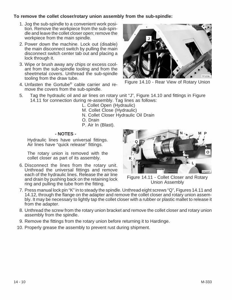
To remove the collet closer/rotary union assembly from the sub-spindle:
1. Jog the sub-spindle to a convenient work posi-tion. Remove the workpiece from the sub-spin-dle and leave the collet closer open; remove theworkpiece from the main spindle.
2. Power down the machine. Lock out (disable)the main disconnect switch by pulling the maindisconnect switch center tab out and placing alock through it.
3. Wipe or brush away any chips or excess cool-ant from the sub-spindle tooling and from thesheetmetal covers. Unthread the sub-spindletooling from the draw tube.
4. Unfasten the Gortube® cable carrier and re-move the covers from the sub-spindle.
5. Tag the hydraulic oil and air lines on rotary unit “J”, Figure 14.10 and fittings in Figure14.11 for connection during re-assembly. Tag lines as follows:
L. Collet Open (Hydraulic)M. Collet Close (Hydraulic)N. Collet Closer Hydraulic Oil DrainO. DrainP. Air In (Blast).
- NOTES -Hydraulic lines have universal fittings.Air lines have “quick release” fittings.
The rotary union is removed with thecollet closer as part of its assembly.
6. Disconnect the lines from the rotary unit.Unthread the universal fittings and removeeach of the hydraulic lines. Release the air lineand drain by pushing back on the retaining lockring and pulling the tube from the fitting.
7. Press manual lock pin “K” in to steady the spindle. Unthread eight screws “Q”, Figures 14.11 and14.12, through the flange on the adapter and remove the collet closer and rotary union assem-bly. It may be necessary to lightly tap the collet closer with a rubber or plastic mallet to release itfrom the adapter.
8. Unthread the screw from the rotary union bracket and remove the collet closer and rotary unionassembly from the spindle.
9. Remove the fittings from the rotary union before returning it to Hardinge.10. Properly grease the assembly to prevent rust during shipment.
14 - 10 M-333
Figure 14.10 - Rear View of Rotary Union
J
TP1036.
Figure 14.11 - Collet Closer and RotaryUnion Assembly
TP1037.
K
Q
N M
O
L
P
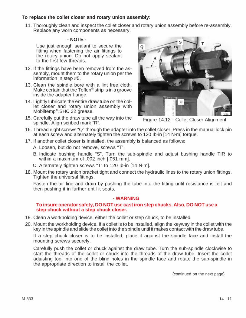
To replace the collet closer and rotary union assembly:
11. Thoroughly clean and inspect the collet closer and rotary union assembly before re-assembly.Replace any worn components as necessary.
- NOTE -Use just enough sealant to secure thefitting when fastening the air fittings tothe rotary union. Do not apply sealantto the first few threads.
12. If the fittings have been removed from the as-sembly, mount them to the rotary union per theinformation in step #5.
13. Clean the spindle bore with a lint free cloth.Make certain that the Teflon® strip is in a grooveinside the adapter flange.
14. Lightly lubricate the entire draw tube on the col-let closer and rotary union assembly withMobiltemp® SHC 32 grease.
15. Carefully put the draw tube all the way into thespindle. Align scribed mark “R”.
16. Thread eight screws “Q” through the adapter into the collet closer. Press in the manual lock pinat each screw and alternately tighten the screws to 120 Ib-in [14 N·m] torque.
17. If another collet closer is installed, the assembly is balanced as follows:A. Loosen, but do not remove, screws “T”.B. Indicate bushing handle “S”. Turn the sub-spindle and adjust bushing handle TIR to
within a maximum of .002 inch [.051 mm].C. Alternately tighten screws “T” to 120 Ib-in [14 N·m].
18. Mount the rotary union bracket tight and connect the hydraulic lines to the rotary union fittings.Tighten the universal fittings.Fasten the air line and drain by pushing the tube into the fitting until resistance is felt andthen pushing it in further until it seats.
- WARNINGTo insure operator safety, DO NOT use cast iron step chucks. Also, DO NOT use astep chuck without a step chuck closer.
19. Clean a workholding device, either the collet or step chuck, to be installed.20. Mount the workholding device. If a collet is to be installed, align the keyway in the collet with the
key in the spindle and slide the collet into the spindle until it makes contact with the draw tube.If a step chuck closer is to be installed, place it against the spindle face and install themounting screws securely.
Carefully push the collet or chuck against the draw tube. Turn the sub-spindle clockwise tostart the threads of the collet or chuck into the threads of the draw tube. Insert the colletadjusting tool into one of the blind holes in the spindle face and rotate the sub-spindle inthe appropriate direction to install the collet.
(continued on the next page)
M-333 14 - 11
Figure 14.12 - Collet Closer AlignmentTP1037.
U
TSQ
R
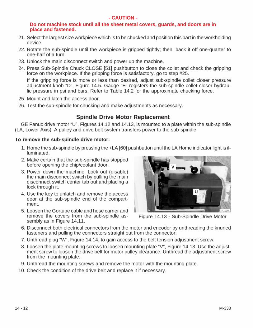
- CAUTION -Do not machine stock until all the sheet metal covers, guards, and doors are inplace and fastened.
21. Select the largest size workpiece which is to be chucked and position this part in the workholdingdevice.
22. Rotate the sub-spindle until the workpiece is gripped tightly; then, back it off one-quarter toone-half of a turn.
23. Unlock the main disconnect switch and power up the machine.24. Press Sub-Spindle Chuck CLOSE [51] pushbutton to close the collet and check the gripping
force on the workpiece. If the gripping force is satisfactory, go to step #25.If the gripping force is more or less than desired, adjust sub-spindle collet closer pressureadjustment knob “D”, Figure 14.5. Gauge “E” registers the sub-spindle collet closer hydrau-lic pressure in psi and bars. Refer to Table 14.2 for the approximate chucking force.
25. Mount and latch the access door.26. Test the sub-spindle for chucking and make adjustments as necessary.
Spindle Drive Motor ReplacementGE Fanuc drive motor “U”, Figures 14.12 and 14.13, is mounted to a plate within the sub-spindle
(LA, Lower Axis). A pulley and drive belt system transfers power to the sub-spindle.
To remove the sub-spindle drive motor:
1. Home the sub-spindle by pressing the +LA [60] pushbutton until the LA Home indicator light is il-luminated.
2. Make certain that the sub-spindle has stoppedbefore opening the chip/coolant door.
3. Power down the machine. Lock out (disable)the main disconnect switch by pulling the maindisconnect switch center tab out and placing alock through it.
4. Use the key to unlatch and remove the accessdoor at the sub-spindle end of the compart-ment.
5. Loosen the Gortube cable and hose carrier andremove the covers from the sub-spindle as-sembly as in Figure 14.11.
6. Disconnect both electrical connectors from the motor and encoder by unthreading the knurledfasteners and pulling the connectors straight out from the connector.
7. Unthread plug “W”, Figure 14.14, to gain access to the belt tension adjustment screw.8. Loosen the plate mounting screws to loosen mounting plate “V”, Figure 14.13. Use the adjust-
ment screw to loosen the drive belt for motor pulley clearance. Unthread the adjustment screwfrom the mounting plate.
9. Unthread the mounting screws and remove the motor with the mounting plate.10. Check the condition of the drive belt and replace it if necessary.
14 - 12 M-333
Figure 14.13 - Sub-Spindle Drive MotorTP1035.
V
U

To remount the sub-spindle drive motor:
11. If the drive motor is to be replaced, unthread thedrive motor mounting screws and removemounting plate from motor.When remounting a motor to the mountingplate, tighten the screws to 50 lb-ft [68 N•m]torque.
12. Make certain that the belt is on the sub-spindlepulley teeth, align the motor drive pulley in thebelt, and refasten the mounting plate and drivemotor with the mounting screws hand tight.
- NOTE -Correct belt tension is .12 inch [3.2mm]belt deflection at 2.4-2.6 lb. [1.09-1.18kg.] force.
13. Start the belt tension adjustment screw a few threads into the mounting plate. Adjust the belttension using the adjustment screw to move the motor flange. Tighten four mounting screws to50 lb-ft [68 N•m] torque to secure mounting plate and drive motor.
14. Align the electrical connections on the motor and encoder; push the connector straight in. Eachconnector can fit together only one way. Thread the knurled nut on to fasten each connector inplace.
15. Mount the covers and fasten the Gortube® cable and hose carrier on the sub-spindle assembly.16. Mount and latch the access door.
To synchronize the sub-spindle with the main spindle:
- WARNING -Extreme safety must be practiced by a qualified technician when working in thepower case. Make certain that the power is OFF when in the power case.
17. Reset the sub-spindle and enter the following program:01158M3 S50M32 S5M7S0M30
(continued on the next page)
M-333 14 - 13
Figure 14.14 - Belt TensionAdjustment Screw
TP1034.
W

18. Adjust the parameters as follows: Set K07.1=1A. Make certain that the control is ON and then put it in MDI mode.B. Press the Emergency Stop (E-Stop) [74] pushbutton and make certain that it remains
down.C. Press the OFFSET SETTING key to display the Setting (HANDY) page.D. Press the PAGE down ( � ) or up ( � ) until the cursor is at Parameter WRITE.E. Change Parameter WRITE from 0 to 1. Press key 1 and then the INPUT soft key or IN-
PUT key.F. Press the SYSTEM key and DGNS soft key. Enter 416 and press the No.SEARCH soft
key.G. Turn PROGRAM PROTECT key to the OFF position.
- NOTE -To read or change the K-word address, the number to the left of the decimal pointis the K-word address. The number to the right of the decimal point identifies aspecific bit of that word. K-word address K07.1 represents bit 1 of word K07
7 6 5 4 3 2 1 0
EXAMPLE: To monitor K07.1 the CRT will display “K07 00000010".
1. Record the eight DATA numbers at Diagnostic K07 __ __ __ __ __ __ __ __K-word address K07.1 must be set to 1.
2. Set the specified bit for the address to 1 as follows:a. Press CURSOR down ( � ) or up ( � ) to the designated K-word number.b. Enter the DATA number with the bit change. The number will be displayed near
the bottom of the screen.c. Press the INPUT key.
H. Cursor to K07. Record the eight bits shown. Then, enter the bits with changes andpress INPUT.
19. Install a collet for square stock or a collet for the workpiece into the sub-spindle and a collet forthe same square stock or mating collet for the workpiece into the main spindle. Leave thesub-spindle collet closer in an open position during this set up.
20. Run program in single block mode.21. With spindle rotating in “M7 S5" watch for the locating dog on the main spindle face to come into
view.22. When the locating dog is at the top, press the CYCLE START [72] pushbutton again.23. Slide square stock or workpiece into the main collet. Leave the main spindle collet closer open
during this procedure.24. Press SYSTEM key on the CRT/MDI control panel. Then press DGNOS soft key, input 416,
press No.SEARCH soft key. DGNS 416 is displayed.25. Jog the sub-spindle all the way toward the main spindle.
14 - 14 M-333

- NOTE -Sub-spindle will turn when button is released. Remove the stock or workpiece fromone collet before releasing the PROGRAM 2 button.
26. Press and hold PROGRAM 2 button on the operators panel.27. With PROGRAM 2 depressed, observe DGNS 416 while turning the sub-spindle by hand until
the square stock slides freely into both collets. Do not leave stock or the workpiece in both col-lets when releasing the PROGRAM 2 button.
28. Record the number in DGNS 416 and input the opposite value in Parameter 4034 S2 as follows:A. Press SYSTEM hard key.B. Press PARAMETER soft key.C. Enter 4 0 3 4D. Press No.SEARCH soft key.E. Cursor down to S2F. Type in the opposite value that was found in DGNS 416G. Press the INPUT soft key or INPUT key.
29. Rerun the program and check to see that the locating dogs are aligned.30. Reset the specified bit from Diagnostic K07.1 address to 0 as follows:
Set K07.1=0A. Press the Emergency Stop (E-Stop) [74] pushbutton and make certain that it is down.B. Press the OFFSET SETTING key to display the Setting (HANDY) page.C. Press the PAGE down ( � ) or up ( � ) until the cursor is at Parameter WRITE.D. Change Parameter WRITE from 1 to 0. Press key 0 and then the INPUT soft key or IN-
PUT key.31. Rerun the program and check to see that the locating dogs are aligned.32. Make certain that all guards, covers, and doors are in place before cutting stock.
M-333 14 - 15
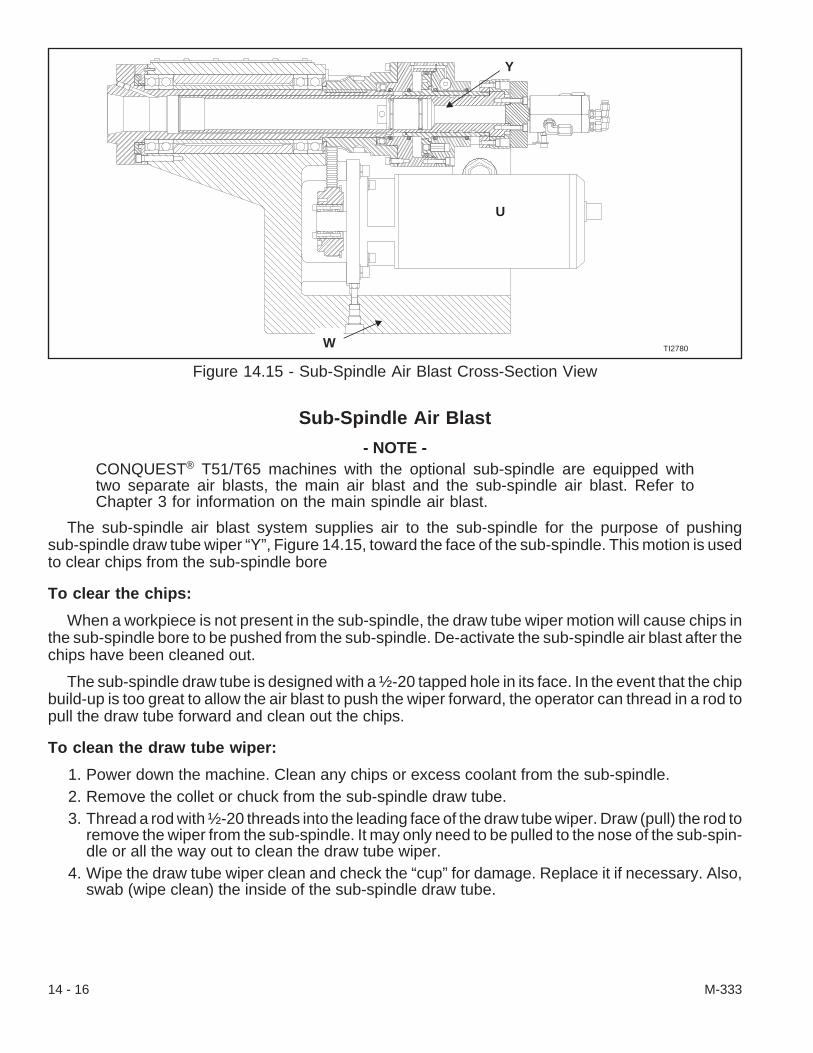
Sub-Spindle Air Blast
- NOTE -CONQUEST® T51/T65 machines with the optional sub-spindle are equipped withtwo separate air blasts, the main air blast and the sub-spindle air blast. Refer toChapter 3 for information on the main spindle air blast.
The sub-spindle air blast system supplies air to the sub-spindle for the purpose of pushingsub-spindle draw tube wiper “Y”, Figure 14.15, toward the face of the sub-spindle. This motion is usedto clear chips from the sub-spindle bore
To clear the chips:
When a workpiece is not present in the sub-spindle, the draw tube wiper motion will cause chips inthe sub-spindle bore to be pushed from the sub-spindle. De-activate the sub-spindle air blast after thechips have been cleaned out.
The sub-spindle draw tube is designed with a ½-20 tapped hole in its face. In the event that the chipbuild-up is too great to allow the air blast to push the wiper forward, the operator can thread in a rod topull the draw tube forward and clean out the chips.
To clean the draw tube wiper:
1. Power down the machine. Clean any chips or excess coolant from the sub-spindle.2. Remove the collet or chuck from the sub-spindle draw tube.3. Thread a rod with ½-20 threads into the leading face of the draw tube wiper. Draw (pull) the rod to
remove the wiper from the sub-spindle. It may only need to be pulled to the nose of the sub-spin-dle or all the way out to clean the draw tube wiper.
4. Wipe the draw tube wiper clean and check the “cup” for damage. Replace it if necessary. Also,swab (wipe clean) the inside of the sub-spindle draw tube.
14 - 16 M-333
Figure 14.15 - Sub-Spindle Air Blast Cross-Section View
Y
U
W TI2780

5. Put the wiper into the insertion tool (tube) with the cup going into the tube last. Align the tube inthe nose of the sub-spindle and put it in until it stops; use a nylon or soft metal rod to push thewiper out of the insertion tube and into the sub-spindle.
6. Mount the sub-spindle collet or chuck.7. Power up the machine.8. Test the sub-spindle draw tube wiper and make adjustments as necessary.
To adjust the sub-spindle air flow:
Sub-spindle air blast pressure is set by flow control valve “Z”, Figure 14.16, mounted below its sole-noid valve on the air filter/regulator panel at the rear of the machine. The air pressure on the sub-spin-dle draw tube wiper can be controlled from OFF to a maximum of 80 psi. When the machine’s airsystem is active, an air blast can help remove a workpiece from the sub-spindle workholding tool andcan clean chips from the draw tube. The workpiece or a rod can push the air piston back in the drawtube. An M46 in the program will activate the air blast and an M47 will shut the air off.
The air blast is carried through the collet closer and rotary union assembly from the standard airsupply system and there is no maintenance except to be certain that the air line is clean and that theflow control valve is functioning. The air line that carries the air blast is connected to the rear of the ro-tary union at “P”, Figure 14.11, by an elbow and “quick-disconnect” fitting.
- NOTES -Find the air line that is labeled“sub-spindle air blast” to identify thesolenoid valve and flow control valve.
Some flow control valves have thestem on the bottom and some are onthe front.
The air blast force can be adjusted by threadingthe thumb screw on the flow control valve in or out,depending on what air pressure is needed. Rotatethe knob on flow control valve “Z”, Figure 14.16,clockwise or counter-clockwise (as viewed from theend of the stem) to decrease or increase the air flowrate, respectively.
M-333 14 - 17
Figure 14.16 - Air Panel ManifoldTP1038.
Z

Sub-Spindle Collet Closer Hydraulic ManifoldSub-spindle equipped machines require that an additional manifold, valve, and hose assembly be
incorporated with the standard hydraulic system. Refer to Figure 14.17.
There are no moving parts in the manifold block itself so the solenoid valve is what needs to bechecked or replaced. All of the hydraulic hoses are connected to standard fittings.
To replace pressure gauge “A”:
1. Power down the machine. Lock out (disable)the main disconnect switch by pulling the maindisconnect switch center tab out and placing alock through it.
2. Unthread the screws and remove the coveraround the hydraulic module.
3. Secure the fitting behind the gauge andunthread the gauge.
4. Check the gauge for dirt particles or contami-nants before replacing it.
5. Use pipe dope or Teflon® tape to seal thethreads of the replacement gauge.
6. Hand tighten the new gauge into the fitting. Usea wrench to tighten the gauge in place only untilthe numbers on the gauge can be read in an up-right position.
7. Unlock the main disconnect switch and powerup the machine.
8. Check the replacement gauge operation and check for hydraulic leaks around the fitting.Tighten the fitting as necessary.
To replace solenoid valve(s) “B”:
The solenoid valves control whether the collet is opened or closed.
1. Power down the machine. Lock out (disable) the main disconnect switch by pulling the main dis-connect switch center tab out and placing a lock through it.
2. Locate the additional sub-spindle hydraulic components in front of the air panel and above thehydraulic system heat exchanger.
3. Unthread the screws and remove the cover around the hydraulic module. Unthread the screwand remove the molded LED connectors (plugs) from the solenoid valve.
4. Unthread the four screws that fasten the solenoid valve to the manifold.5. Mount the replacement solenoid valve on the manifold. Make certain that O-rings are in place on
the valve and that the locating pins are set before fastening the valve.6. Mount the molded LED connectors on the valve and fasten them in place.7. Power up the machine. Test the operation of the replacement solenoid valve and/or molded LED
plug.8. Check for leaks around the valve mount on the manifold. Tighten the mounting screws as neces-
sary.
14 - 18 M-333
Figure 14.17 - Sub-SpindleHydraulic Components
TP1039.
D
A
B
C
To replace the molded LED connector(s) “C”, Figure 14.17:
1. Mark the molded LED connector to be replaced.2. Power down the machine. Lock out (disable) the main disconnect switch by pulling the main dis-
connect switch center tab out and placing a lock through it.3. Unthread the screws and remove the cover around the hydraulic module.4. Unthread the screw and remove the molded LED connector (plug) being replaced.5. Follow the lead cable from the plug to the terminal strip.6. Make a wiring diagram so that the wires will be reconnected to the proper terminals.7. Disconnect the wires from the terminals.8. Remove the lead cable from the bundle going to the terminal strip.9. Replace the molded LED plug and cable. Use a cable tie or feed the cable into the bundle.
10. Follow the diagram from step #6 to reconnect the new wires to the terminal strip.11. Mount the molded LED connector on the solenoid valve(s) and fasten it in place.12. Power up the machine and test the operation of the replacement molded LED plug.
To replace the mechanical valve (pressure regulator) “D”:
The collet pressure regulator must be replaced as a unit. It is located on the additional sub-spindlehydraulic manifold.
1. Identify the valve location.2. Power down the machine. Lock out (disable) the main disconnect switch by pulling the main dis-
connect switch center tab out and placing a lock through it.3. Unfasten the screws and remove the cover to the hydraulic module.4. Use a wrench on the hex surface and unthread the valve.5. Clean the replacement valve before mounting it.6. Use pipe dope or Teflon® tape to seal the threads on the replacement valve.7. Hand tighten the new valve into the manifold. Use a wrench to tighten the valve in place.8. Power up the machine.9. Test the operation of the replacement valve and adjust it as necessary.
10. Check for leaks around the valve and tighten it as necessary.
M-333 14 - 19

Ball Screw Driven Sub-Spindle Drive Motor/Drive BeltGE Fanuc drive motor “E”, Figures 14.18, is mounted to a plate mounted on the right end of the
Harcrete® base on the end and below the sub-spindle (LA, Lower Axis). It has a pulley and drive beltsystem that transfers power to the ball screw pulley.
To remove the sub-spindle drive belt and drive motor:
1. Home the sub-spindle, if possible, by pressing the +LA [60] pushbutton until the LA Home indi-cator light is illuminated.
2. Make certain that the sub-spindle has stopped before opening the chip/coolant door.3. Power down the machine. Lock out (disable) the main disconnect switch by pulling the main dis-
connect switch center tab out and placing a lock through it.4. Use the key to unlatch and remove the access
door at the sub-spindle end of the compart-ment.
5. Loosen the Gortube® cable and hose carrierand remove the covers from the sub-spindle as-sembly as in Figure 14.11.
6. Disconnect both-electrical connectors from themotor and encoder by unthreading the knurledfasteners and pulling the connectors straightout from the connector.
7. Unthread the screws and remove cover “F’, togain access to the drive belt and plate mountingscrews ”H", Figure 14.19, inside.
8. Loosen plate mounting screws “H” just enoughto loosen the mounting plate and release ten-sion on the drive belt and, then, remove thedrive belt.
9. Unthread mounting screws “G”, Figures 14.18and 14.19, and remove the sub-spindle drivemotor.
10. Check the condition of the drive belt and re-place it if necessary.
To remount the sub-spindle drive motor anddrive belt:
11. If the drive motor is to be replaced, check themotor pulley and mount it on the new motor ifnecessary. Install the key and lockwasher andtighten the nut to 17 Ib-ft [23 N·m] torque.When remounting the motor to the mountingplate, tighten mounting screws “G”, to 25 lb-ft[34 N·m] torque.
14 - 20 M-333
Figure 14.18 - Ball Screw DrivenSub-Spindle Drive Motor
TP1031.
EG
F
Figure 14.19 - Sub-Spindle Ball ScrewDrive Belt and Drive Motor
TI3284.
E
G
H
F
H

12. Make certain that the belt is on the ball screw pulley teeth and motor drive pulley teeth; move theplate enough to put tension on the drive belt. Tighten plate mounting screws “H” hand tight.
- NOTECorrect belt tension is .15 inch [3.8mm] belt deflection at 1.5-3.0 lb. [0.67 - 1.33kg.]force.
13. Move the mounting plate to adjust the belt tension within specification. Secure the mountingplate by tighten mounting screws “H”, to 70 Ib-ft [95 N·m] torque.
14. Align the electrical connections on the motor and encoder; push the connector straight in. Eachconnector can fit together only one way. Thread the knurled nut on to fasten each connector inplace.
15. Mount the covers and fasten the Gortube® cable and hose carrier on the sub-spindle assembly.16. Mount and latch the access door.
To set the fine Home position:
The sub spindle Zero Return (Home) set up parameters 1240Y, 1250Y, 1251Y, 1320Y, and 1321Yfor the specific machine are set at the factory.
- NOTES -Software overtravels can be disabled by powering up the control while pressing theCAN and P pushbuttons at the same time.
Make certain that there are no offsets or workshifts active. Press the CONTROLOFF pushbutton and then the CONTROL ON pushbutton whenever the grid shiftparameters are changed to activate the new parameters.
17. Zero Return the axes as follows:A. Press and hold the -LA [58] pushbutton to jog the sub-spindle approximately 1.00 inch
[25 mm] or more in the minus direction.B. Press and hold the -Z [64] pushbutton to jog the carriage approximately 1.00 inch [25
mm] in the minus direction.C. Press and hold the -X [67] pushbutton to jog the cross slide approximately 1.00 inch [25
mm] in the minus direction.
- NOTEThe cross slide must be homed before the carriage; and then, the sub-spindle.
D. Press the +X [63] pushbutton. The cross slide will move to the X Home position and theindicator light will turn on.
E. Press the +Z [66] pushbutton. The carriage will move to the Z Home position and the in-dicator light will tum on.
F. Press the +LA [60] pushbutton. The sub-spindle will move to its Home position.18. In JOG mode press -LA and +LA pushbuttons as necessary to move the sub-spindle face near
3.000 as seen on the CRT display. Use the following steps to dial in 3.000:A. Press POSITION key under HANDLE; then, press the .0001" .001 mm pushbutton.B. Use the handwheel to move the axis until Y 3.0000 [76.200] is displayed.
M-333 14 - 21

19. Press the RELATIVE key, press ORIGIN to reveal all and then press the CAN (cancel) key to setthe Relative position register to 0 (zero).
20. Place a 3.00 inch gauge block against the spindle face. Use the handwheel to move thesub-spindle until the gauge block has a slip fit between the sub-spindle face and the spindleface.
21. Record the Relative Y dimension displayed on the screen. Be sure to include the negative sign ifone is displayed.
- NOTEThe Y dimension displayed on the screen is the Y Home Error Value.
22. Convert the Home Error Value to a grid shift value as follows:CONQUEST® 51 and CONQUEST 65 Precision Chucker and Bar Machines:Multiply the Home Error Value by 25.4; then divide that number by .001.
Example: Home Error Value = -.060-.060 x 25.4 = -1.524
-1.524 x .001 = -1524Grid shift value = -1524
CONQUEST 51SP Super-Precision® Chucker and Bar Machine:Multiply the Home Error Value by 25.4; then divide that number by .002.
Example: Home Error Value = -.060-.060 x 25.4 = -1.524
-1.524 x .002 = -1524Grid shift value = -762
23. Press the E-Stop [74] pushbutton and make sure it locks down.24. Press the SYSTEM key and PARAMETER soft key.25. Enter 1 8 5 0 and press the No.SRCH (search) soft key. The cursor will be flashing at Parameter
1850.26. Key in the value from step #22 in Parameter 1850Y. Include the minus sign if the value is nega-
tive. Press the INPUT key.27. Press the CONTROL OFF pushbutton. Wait a few minutes and press the CONTROL ON
pushbutton.28. Zero Retum the axes.29. Use the Axis Jog pushbuttons and the MPG handwheel to move the Y-axis sub-spindle face to
3.00 inches from the spindle face.30. Check for a slip fit with the 3.00 inch gauge block.31. Record the final Grid Shift value from step #22 on the control data sheet in the machine package
for future reference.
14 - 22 M-333

32. Change Parameter WRITE back to 0 (zero) as follows:A. Press the E-Stop (Emergency Stop) [74] pushbutton and make certain that it remains
down.B. Press the OFFSET SETTING key to display the Setting (HANDY) page.C. Press the PAGE down ( � ) or up ( � ) until the curser is at Parameter WRITE.D. Change Parameter WRITE from 1 to 0. Press key 0 and then the INPUT soft key or IN-
PUT key.E. Press the RESET key.
33. Rerun the program and verify that the 3.000 inch gauge block just has a slip fit between thesub-spindle face and the spindle face; adjust the fit as necessary beginning with step #17.
34. Make certain that all guards, covers, and doors are in place before cutting stock.
SUB-SPINDLE PART CATCHERThe optional, sub-spindle, overhead part catcher is available as original equipment ONLY. The part
catcher moves on a linear axis between the UNLOAD PART position (toward the sub-spindle end ofthe machine) and the MIDPOINT position (toward the headstock end of the machine).
When the part catcher reaches the UNLOAD PART position, the workpiece is mechanically trans-ferred from the part holder to the part bucket (tray). The tray is accessible from outside on thesub-spindle (right) front of the machine.
When the part catcher reaches the MIDPOINT position and after an ARM EXTEND command, itthen can move to either the main spindle or the sub-spindle.
LUBRICATIONEvery 160 hours or as necessary - Grease the “rodless” cylinder block on thecenter of the part catcher rail at least once every month.
The “rodless” cylinder block is equipped with grease fitting “I”, Figure 14.20, in the area where theextension arm connects to the overhead rails. Apply a NLGI 2 water-resistant grease at the fitting untilgrease is forced out of the seals on the block.
Every 500 hours or as necessary - Lubricate the part catcher slide rails and thepart holder pivot bracket at least once every three months.
- WARNING -Be sure to clean all chips from the slide rails and slide packs before applying lu-brication. Personal injury may result if contact is made with chips during clean-ing and lubrication.
M-333 14 - 23

To lubricate slide rails “J”, Figure 14.20:
1. Lock out the machine air system as follows:A. Press the Emergency Stop (E-Stop) [74] pushbutton.B. Turn the main air valve OFF at the back of the machine and lock it out.
2. Open the main coolant guard door. Use the key to unfasten both latches and remove the serviceaccess cover at the sub-spindle (right) end of the machine.
3. Carefully clean all chips and grease from both sets of slide rails “J”, with a lint-free cloth.4. Apply NLGI 2 water-resistant grease the full length of each slide rail and at locations “K” and “L”
on both sets of rails.5. Mount the service access cover and close the coolant guard door.6. Enable machine operation as follows:
A. Unlock the main air valve and turn it ON.B. Turn the E-Stop [74] pushbutton clockwise to release it.C. Press the E-Stop Reset [73] pushbutton.
14 - 24 M-333
Figure 14.20 - Extension Arm on Sub-Spindle Parts
J
I
K
L
J
TI2899
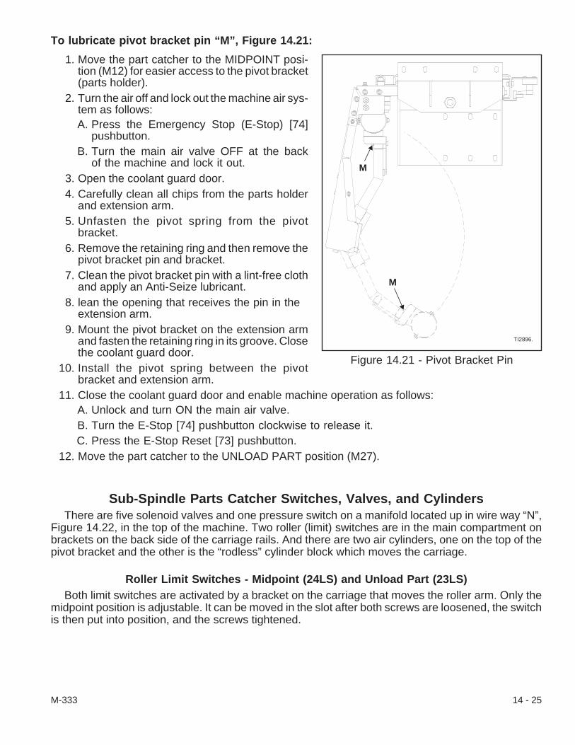
To lubricate pivot bracket pin “M”, Figure 14.21:
1. Move the part catcher to the MIDPOINT posi-tion (M12) for easier access to the pivot bracket(parts holder).
2. Turn the air off and lock out the machine air sys-tem as follows:A. Press the Emergency Stop (E-Stop) [74]
pushbutton.B. Turn the main air valve OFF at the back
of the machine and lock it out.3. Open the coolant guard door.4. Carefully clean all chips from the parts holder
and extension arm.5. Unfasten the pivot spring from the pivot
bracket.6. Remove the retaining ring and then remove the
pivot bracket pin and bracket.7. Clean the pivot bracket pin with a lint-free cloth
and apply an Anti-Seize lubricant.8. lean the opening that receives the pin in the
extension arm.9. Mount the pivot bracket on the extension arm
and fasten the retaining ring in its groove. Closethe coolant guard door.
10. Install the pivot spring between the pivotbracket and extension arm.
11. Close the coolant guard door and enable machine operation as follows:A. Unlock and turn ON the main air valve.B. Turn the E-Stop [74] pushbutton clockwise to release it.C. Press the E-Stop Reset [73] pushbutton.
12. Move the part catcher to the UNLOAD PART position (M27).
Sub-Spindle Parts Catcher Switches, Valves, and CylindersThere are five solenoid valves and one pressure switch on a manifold located up in wire way “N”,
Figure 14.22, in the top of the machine. Two roller (limit) switches are in the main compartment onbrackets on the back side of the carriage rails. And there are two air cylinders, one on the top of thepivot bracket and the other is the “rodless” cylinder block which moves the carriage.
Roller Limit Switches - Midpoint (24LS) and Unload Part (23LS)Both limit switches are activated by a bracket on the carriage that moves the roller arm. Only the
midpoint position is adjustable. It can be moved in the slot after both screws are loosened, the switchis then put into position, and the screws tightened.
M-333 14 - 25
Figure 14.21 - Pivot Bracket Pin
TI2896.
M
M

To replace the sub-spindle part catcher midpoint and unload part limit switches:
1. Move the part catcher to a convenient work position away from either switch being replaced.(M27 to move the part catcher to the unload part position and M12 to move it to the midpoint posi-tion.)
2. Power down the machine. Make sure that the air valve is turned OFF and locked out.3. Open the main coolant guard door. Use the key
to unfasten both latches and remove the ser-vice access cover at the sub-spindle end.
4. Unthread the screws and remove access cover“N”, Figure 14.22, over the wire way on top ofthe machine.
5. Unthread the screws and remove theswitch(es) from its bracket.
6. Install the switch(es) on the bracket and tightenthe screws.
7. Use the key to unfasten both latches and openthe Input/Output (I/O) case door. Follow cable141 from the midpoint limit switch or cable 140from the unload part limit switch through thewire way and into the I/O case.
8. Route the cable from the replacementswitch(es) up into the wire way and into the I/Ocase.
9. Connect the wire(s) for the new switch(es) as follows:A. Check the switch wire connections against the connections listed below. Make notes of
any changes as necessary.Terminal Block Connections:
24LS (midpoint reference) - Cable 141Black Wire to 4TB9
White Wire to 22TB323LS (unload part reference) - Cable 140
Black Wire to 4TB8White Wire to 22TB2
B. Disconnect the wires from the terminal block connections.C. Connect the wires to the terminal block connections per step A, above.D. Close and latch the I/O case door.
10. Close the coolant guard door and fasten the access covers in place.11. Enable machine operation as follows:
A. Unlock and turn ON the main air valve.B. Turn the E-Stop [74] pushbutton clockwise to release it.C. Press the E-Stop Reset [73] pushbutton.
12. If the midpoint limit switch was replaced, then, move the part catcher to the unload part position(M27) and if the unload part switch was replaced, then, move the parts catcher to the midpointlimit switch (M12) and back to the unload part position (M27).
14 - 26 M-333
Figure 14.22 - Wire Way Access Cover(Machine Top View)
TI2901.
N

Solenoid ValvesThe solenoid valves and pressure switch are stacked on an air manifold in wire way “N”, Figure
14.22, in the top of the machine. The five valves and solenoid designation are as follows: the Start Up(14 Sol), move Carriage Right (8A Sol), move Carriage Left (8B Sol), Extend Arm (2A Sol), and Re-tract Arm (2B Sol) solenoid valves.
To replace a sub-spindle part catcher solenoid valve:
1. Power down the machine. Make certain that the air lock out valve is OFF and that the main dis-connect switch and the air locked out valve are both locked out.
2. Refer to the schematic chart on the panel to identify which valve needs to be replaced.3. Unthread the screw and remove the end plate from the stack of solenoid valves.
Or, if the valve is mounted directly to the manifold, just unthread and remove it.
4. If necessary, unthread the two screws that mount the end cap and each valve to its adjacentvalve until the valve to be replaced is removed from the stack of valves.
- NOTE -Do not remove the electrical connection or air line from the valves that are notbeing replaced.
5. Unthread the screw that secures the electrical connection to the solenoid valve being replaced.Pull the connection straight up to release it from the valve.
6. Unthread the air line from the fitting on the bottom of the valve being replaced. If necessary, re-move the pneumatic fitting from the valve.
7. Thread the air fitting to the new valve. Use sealant to secure the fitting but do not apply it to thefirst few threads.
8. Mount the new valve to the adjacent valve on the panel or directly to the manifold. Check thevalve gaskets and replace any that are worn. Fasten each valve and gasket in place.If necessary, check the gaskets and mount the other valves and end plate.
9. Support the new valve and fit the electrical connection to it. Secure the connection with its screw.10. Fasten the air line to the fitting on the bottom of the valve.11. Unlock the main disconnect switch and air lock out valve and power up the machine. Set the reg-
ulator to an operating pressure between 80 and 90 psi [5.5 and 6.3 bars].12. Press the E-Stop Reset [73] pushbutton if it is still necessary to clear “Main Air Pressure Low”
alarm message from the CRT.13. Check the air system bowl for contamination, moisture, or air leaks and correct any problems as
necessary.14. Test the part catcher and adjust it as necessary.
M-333 14 - 27

Pressure SwitchThe pressure switch is designed to send a signal to the control and an alarm message appears on
the CRT if the part catcher arm is not in the retract position.
To replace the arm retract pressure switch:
1. Power down the machine. Make certain that the air lock out valve is OFF and that the main dis-connect switch and the air locked out valve are both locked out.
2. Unthread the screw that holds the electrical plug to the top of the switch. Pull the plug straight upto remove it from the switch.
3. Unthread the pressure switch from the manifold. The switch is tightened to the manifold with lighttorque pressure, however, a wrench may be necessary to unthread it.
- NOTE -Do not apply sealant to the first few threads. Use just enough sealant to secure thefitting when fastening the pressure switch to the manifold.
4. Thread the new pressure switch on the manifold and only tighten it to 50 in/pounds[5.6 N•m].
5. Connect the electric plug to the pressure switch. Secure the plug with its screw.6. Unlock the main disconnect switch and air lock out valve and power up the machine. Set the reg-
ulator to an operating pressure between 70 psi to 90 psi [4.9 to 6.2 bars].7. Press the E-Stop Reset [73] pushbutton if it is still necessary to clear “1505 Illegal use of Parts
Chute” alarm message from the CRT.8. Check the air system bowl for contamination, moisture, or air leaks and correct any problems as
necessary.
- NOTES -
14 - 28 M-333
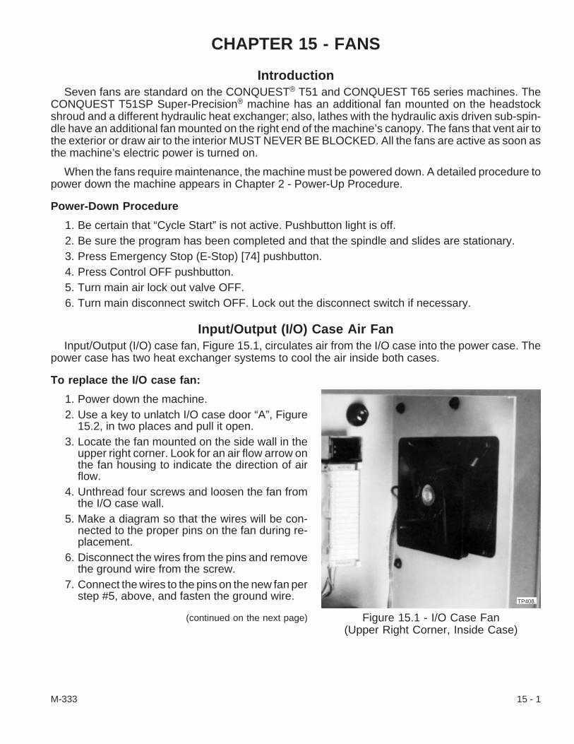
CHAPTER 15 - FANS
IntroductionSeven fans are standard on the CONQUEST® T51 and CONQUEST T65 series machines. The
CONQUEST T51SP Super-Precision® machine has an additional fan mounted on the headstockshroud and a different hydraulic heat exchanger; also, lathes with the hydraulic axis driven sub-spin-dle have an additional fan mounted on the right end of the machine’s canopy. The fans that vent air tothe exterior or draw air to the interior MUST NEVER BE BLOCKED. All the fans are active as soon asthe machine’s electric power is turned on.
When the fans require maintenance, the machine must be powered down. A detailed procedure topower down the machine appears in Chapter 2 - Power-Up Procedure.
Power-Down Procedure
1. Be certain that “Cycle Start” is not active. Pushbutton light is off.2. Be sure the program has been completed and that the spindle and slides are stationary.3. Press Emergency Stop (E-Stop) [74] pushbutton.4. Press Control OFF pushbutton.5. Turn main air lock out valve OFF.6. Turn main disconnect switch OFF. Lock out the disconnect switch if necessary.
Input/Output (I/O) Case Air FanInput/Output (I/O) case fan, Figure 15.1, circulates air from the I/O case into the power case. The
power case has two heat exchanger systems to cool the air inside both cases.
To replace the I/O case fan:
1. Power down the machine.2. Use a key to unlatch I/O case door “A”, Figure
15.2, in two places and pull it open.3. Locate the fan mounted on the side wall in the
upper right corner. Look for an air flow arrow onthe fan housing to indicate the direction of airflow.
4. Unthread four screws and loosen the fan fromthe I/O case wall.
5. Make a diagram so that the wires will be con-nected to the proper pins on the fan during re-placement.
6. Disconnect the wires from the pins and removethe ground wire from the screw.
7. Connect the wires to the pins on the new fan perstep #5, above, and fasten the ground wire.
(continued on the next page)
M-333 15 - 1
Figure 15.1 - I/O Case Fan(Upper Right Corner, Inside Case)
TP408.

8. Point the air flow arrow in the same direction as it was pointed in step #3 and mount the new fan.9. Close and latch the I/O case door.
10. Power up the machine.
Power Case FansThe power case is cooled by two heat exchange systems. The heat exchangers provide the cooling
and environmental protection necessary for proper operation of the printed circuit boards. These airunits employ a closed loop design which circulates air inside the power case while sealing out poten-tially contaminated, external air.
Heat exchanger “B”, Figure 15.2, located on the door exterior, has four fans. Air is moved inside thepower case by fans “F”, Figure 15.3, while external air is drawn across the corrugated metal (heat ex-change) plate by fans “C”, Figure 15.2. The second heat exchanger has fan “G”, Figures 15.4 and15.6, located near the spindle compartment that pushes air behind the electric component mountingpanel in the power case.
To replace a power case heat exchanger fan:
1. Power down the machine.2. Replace exterior fan(s) “C”, Figure 15.2, as fol-
lows:A. Unthread two screws “D” that fasten the
mounting box. Pivot the box up to releaseit from the door.
B. Make a diagram of what color wires areconnected to the pins on the fan.
C. Disconnect the wires from the pins andunfasten the ground wire.
D. Use the arrow on the fan housing edge forreference and mark the air flow directionon the mounting box.
E. Unthread the screws and remove thefan(s) from the mounting box.
F. Mount the new fan(s) in the box per theair flow arrows in step D.
G. Connect the wires to the pins per step Band fasten the ground wire.
H. Pivot the mounting box down and fasten itto the door with its screws.
I. Power up the machine and make sure thatthe new fan(s) draws air.
15 - 2 M-333
Figure 15.2 - Power Case DoorHeat Exchanger
B
D
A
C
TP409.
E

3. Replace interior fan(s) “F”, Figure 15.3, as fol-lows:A. Use the key to unlock the power case
door in two places. Wiggle the main dis-connect switch handle further counter-clockwise while pressing the latch clock-wise and pull the door open.
B. Unthread 18 screws “E”, Figure 15.2, andremove the heat exchanger from the door.
C. Make a diagram of what color wires areconnected to the pins on the fan(s).
D. Find the air flow direction arrow on theside of the fan housing and mark themounting box indicating the direction of airflow.
E. Disconnect the wires from the pins and remove the ground wire from the screw.F. Unthread the screws and remove the fan(s) from the mounting box.G. Mount the new fan(s) in the box per the air flow arrows in step D.H. Connect the wires to the pins per step C and fasten the ground wire.I. Fasten the mounting box to the heat exchanger with its screws.J. Mount the heat exchanger to the power case door and fasten it with its screws.K. Power up the machine and make sure that the new fan(s) draws air.
4. Close and lock the power case door before operating the machine.
To replace the fan for the panel heat exchanger (plenum) inside the power case:
The fan for the panel heat exchanger inside the power case is mounted near the lower left corner ofthe spindle drive compartment. Fan “G”, Figure 15.4, sends air through a funnel and into the back ofthe power case behind electric component panel “H”, Figure 15.5. Air is exhausted up through the topof the power case.
1. Power down the machine.2. Unthread the panhead screws and remove spindle compartment cover “I”, Figure 15.6.
M-333 15 - 3
Figure 15.3 - Door InteriorHeat Exchanger Fans
F
TP410.
Figure 15.4 - Power Case Exchanger Fan(Near the Spindle Drive Compartment)
G
TP411
Figure 15.5 - Electric Component Panel
H
TP412.
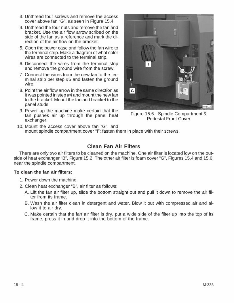
3. Unthread four screws and remove the accesscover above fan “G”, as seen in Figure 15.4.
4. Unthread the four nuts and remove the fan andbracket. Use the air flow arrow scribed on theside of the fan as a reference and mark the di-rection of the air flow on the bracket.
5. Open the power case and follow the fan wire tothe terminal strip. Make a diagram of what colorwires are connected to the terminal strip.
6. Disconnect the wires from the terminal stripand remove the ground wire from the screw.
7. Connect the wires from the new fan to the ter-minal strip per step #5 and fasten the groundwire.
8. Point the air flow arrow in the same direction asit was pointed in step #4 and mount the new fanto the bracket. Mount the fan and bracket to thepanel studs.
9. Power up the machine make certain that thefan pushes air up through the panel heatexchanger.
10. Mount the access cover above fan “G”, andmount spindle compartment cover “I”; fasten them in place with their screws.
Clean Fan Air FiltersThere are only two air filters to be cleaned on the machine. One air filter is located low on the out-
side of heat exchanger “B”, Figure 15.2. The other air filter is foam cover “G”, Figures 15.4 and 15.6,near the spindle compartment.
To clean the fan air filters:
1. Power down the machine.2. Clean heat exchanger “B”, air filter as follows:
A. Lift the fan air filter up, slide the bottom straight out and pull it down to remove the air fil-ter from its frame.
B. Wash the air filter clean in detergent and water. Blow it out with compressed air and al-low it to air dry.
C. Make certain that the fan air filter is dry, put a wide side of the filter up into the top of itsframe, press it in and drop it into the bottom of the frame.
15 - 4 M-333
Figure 15.6 - Spindle Compartment &Pedestal Front Cover
TP2712.
G
I

3. Clean foam air filter “G”, as follows:
- NOTE -The foam air filter is in a frame that has a mesh support back.
A. Grip the foam air filter and carefully pull it from the frame.B. Wash the air filter clean in detergent and water. Squeeze out as much water as possible
and allow it to air dry.C. Make certain that the foam air filter is dry. Compress it enough to carefully fit it in the
frame.4. Power up the machine.
CONQUEST® T51SP Machine Headstock FanThere is an additional fan on CONQUEST T51SP machines that draws air up around the
headstock. It is mounted in the spindle compartment on the headstock shroud.
To replace the headstock cooling fan:
1. Power down the machine.2. Remove pedestal front cover “J”, Figure 15.7,
as follows:A. Unthread the panhead screws and remove
panel “K”.B. Unthread the panhead screws and remove
duct cover “L”, from the pedestal frontcover.
C. Unthread both screws on the left side be-low the lubricator near the floor.
D. Move the coolant tank just enough toreach inside and unthread the screws in-side the pedestal front cover.
E. Reach inside the spindle compartmentand unthread the nuts on the PEM fasten-ers (studs) on the rear of the pedestalfront cover.
F. Reach through the opening at panel “N”and unthread the screws fastening thepedestal front cover to the upper part ofthe frame.
G. Lift the pedestal front cover from theframe. It is not necessary to unfasten orremove the frame.
3. Find fan “M”, Figure 15.8, near the top of the headstock and make a diagram of the power cablewire connections to the fan.
4. Disconnect the power cable wires.5. Unthread four nuts and remove the fan and bracket from the headstock.
(continued on the next page)
M-333 15 - 5
Figure 15.7 - Pedestal Front Cover
L
J
K
TP415.
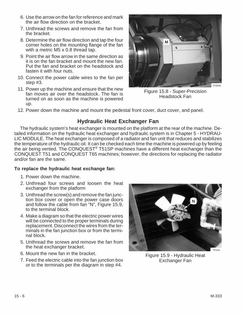
6. Use the arrow on the fan for reference and markthe air flow direction on the bracket.
7. Unthread the screws and remove the fan fromthe bracket.
8. Determine the air flow direction and tap the fourcorner holes on the mounting flange of the fanwith a metric M5 x 0.8 thread tap.
9. Point the air flow arrow in the same direction asit is on the fan bracket and mount the new fan.Put the fan and bracket on the headstock andfasten it with four nuts.
10. Connect the power cable wires to the fan perstep #3.
11. Power up the machine and ensure that the newfan moves air over the headstock. The fan isturned on as soon as the machine is poweredup.
12. Power down the machine and mount the pedestal front cover, duct cover, and panel.
Hydraulic Heat Exchanger FanThe hydraulic system’s heat exchanger is mounted on the platform at the rear of the machine. De-
tailed information on the hydraulic heat exchanger and hydraulic system is in Chapter 5 - HYDRAU-LIC MODULE. The heat exchanger is composed of a radiator and fan unit that reduces and stabilizesthe temperature of the hydraulic oil. It can be checked each time the machine is powered up by feelingthe air being vented. The CONQUEST® T51SP machines have a different heat exchanger than theCONQUEST T51 and CONQUEST T65 machines; however, the directions for replacing the radiatorand/or fan are the same.
To replace the hydraulic heat exchange fan:
1. Power down the machine.2. Unthread four screws and loosen the heat
exchanger from the platform3. Unthread the screw(s) and remove the fan junc-
tion box cover or open the power case doorsand follow the cable from fan “N”, Figure 15.9,to the terminal block.
4. Make a diagram so that the electric power wireswill be connected to the proper terminals duringreplacement. Disconnect the wires from the ter-minals in the fan junction box or from the termi-nal block.
5. Unthread the screws and remove the fan fromthe heat exchanger bracket.
6. Mount the new fan in the bracket.7. Feed the electric cable into the fan junction box
or to the terminals per the diagram in step #4.
15 - 6 M-333
Figure 15.8 - Super-PrecisionHeadstock Fan
TP2845
M
Figure 15.9 - Hydraulic HeatExchanger Fan
N
TP416
8. Make certain that the gasket is in place and mount the fan junction box cover if necessary.9. Power up the machine and ensure that the fan moves air through the radiator.
10. Power down the machine and mount the heat exchanger on the platform. Tighten the fourscrews to 25 lb-ft [34 N•m] torque.
11. Power up the machine.12. Make certain that the vented air has free movement away from the machine.
Hydraulic Axis Driven Sub-Spindle Option FanThe sub-spindle fan is mounted on the right end of the machine canopy next to the right end access
cover. It is only on machines that have the hydraulic axis driven sub-spindle option.
To replace the sub-spindle fan:
1. Power down the machine.2. Unfasten the latches and lift off the right end access cover.3. Unthread the four nuts and remove the fan and bracket. Use the air flow arrow scribed on the
side of the fan as a reference and mark the direction of the air flow on the bracket.4. Follow the fan wire to the terminal strip. Make a diagram of what color wires are connected to the
terminal strip.5. Disconnect the wires from the terminal strip and remove the ground wire from the screw.6. Feed the wires from the new fan to the terminal strip per step #4 and fasten the ground wire.7. Point the air flow arrow in the same direction as it was pointed in step #3 and mount the new fan
to the bracket. Mount the fan and bracket to the panel studs.8. Power up the machine make certain that the fan pushes air flow.9. Power down the machine and install the right end access cover.
10. Power up the machine.
M-333 15 - 7

- NOTES -
15 - 8 M-333
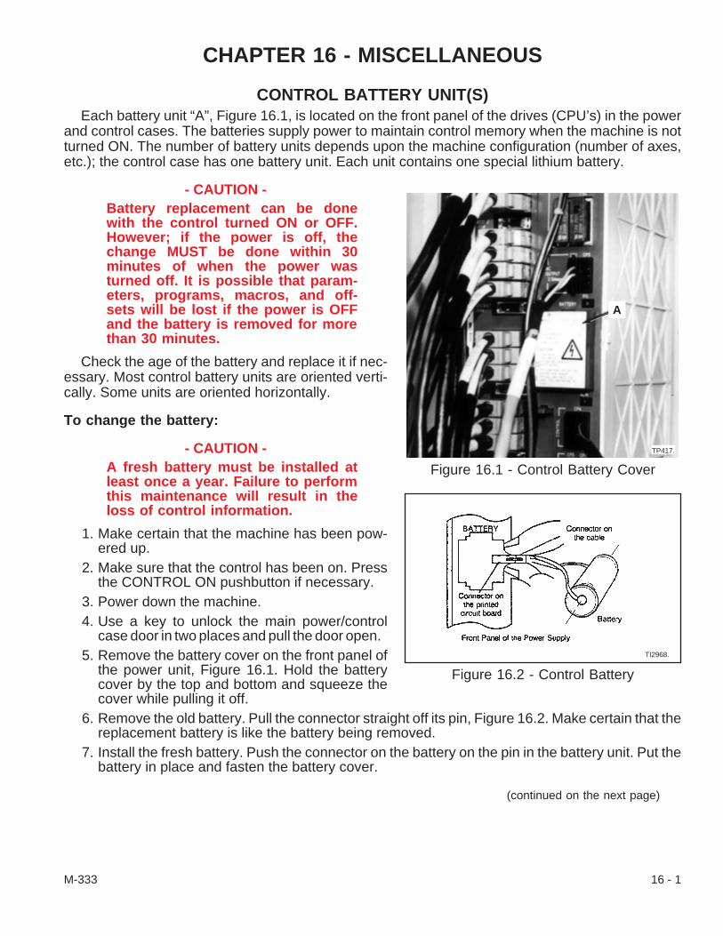
CHAPTER 16 - MISCELLANEOUS
CONTROL BATTERY UNIT(S)Each battery unit “A”, Figure 16.1, is located on the front panel of the drives (CPU’s) in the power
and control cases. The batteries supply power to maintain control memory when the machine is notturned ON. The number of battery units depends upon the machine configuration (number of axes,etc.); the control case has one battery unit. Each unit contains one special lithium battery.
- CAUTION -Battery replacement can be donewith the control turned ON or OFF.However; if the power is off, thechange MUST be done within 30minutes of when the power wasturned off. It is possible that param-eters, programs, macros, and off-sets will be lost if the power is OFFand the battery is removed for morethan 30 minutes.
Check the age of the battery and replace it if nec-essary. Most control battery units are oriented verti-cally. Some units are oriented horizontally.
To change the battery:
- CAUTION -A fresh battery must be installed atleast once a year. Failure to performthis maintenance will result in theloss of control information.
1. Make certain that the machine has been pow-ered up.
2. Make sure that the control has been on. Pressthe CONTROL ON pushbutton if necessary.
3. Power down the machine.4. Use a key to unlock the main power/control
case door in two places and pull the door open.5. Remove the battery cover on the front panel of
the power unit, Figure 16.1. Hold the batterycover by the top and bottom and squeeze thecover while pulling it off.
6. Remove the old battery. Pull the connector straight off its pin, Figure 16.2. Make certain that thereplacement battery is like the battery being removed.
7. Install the fresh battery. Push the connector on the battery on the pin in the battery unit. Put thebattery in place and fasten the battery cover.
(continued on the next page)
M-333 16 - 1
Figure 16.1 - Control Battery Cover
A
TP417.
Figure 16.2 - Control Battery
TI2968.

8. Dispose of the old battery properly.9. Use the key and latch the control case door in both places. Close the power case door and latch
it in both places.10. Power up the machine.
WORKLIGHTThe worklight is mounted on the ceiling of the coolant guard. It is a 36 Watt by 21 fluorescent lamp.
The worklight ballast is located low in the power case; some ballasts are mounted on the componentpanel, however, most are located behind the transformer on the floor.
- WARNING -NEVER perform any work on the electrical components of this or any machinetool while the electrical power is ON.
To replace the lamp and/or starter:
1. Power down the machine. Open the coolantguard door.
2. Wipe the worklight, worklight brackets, andworklight cable clean.
3. Unthread two wing screws “B”, Figures 16.3and 16.4, which hold the worklight bracketsclosed. Open the worklight brackets and re-move the worklight.
4. Loosen, but do not remove, the three screws inthe left end (cable end) cap. Hold the worklightassembly and slide the guard tube from the as-sembly.
5. Replace the fluorescent lamp and/or starter, asnecessary.
- NOTE -During re-assembly, be certain that theend cap is seated tightly against theguard tube when the three screws aretightened. Tightening these screwscauses the rubber seal to expand andgrip the guard tube I.D.
6. Hold the worklight assembly and slide theguard tube up on the assembly. Fasten it bytightening the three screws snug. Secure thescrews but do not overtighten.
7. Mount the worklight in the worklight bracket andfasten both wing screws “B”, loosely.
8. Power up the machine. The light will come onwhen the machine powers up.Adjust the worklight by turning the guard tube. Thread two wing screws in tight to securethe worklight.
16 - 2 M-333
Figure 16.3 - Headwall (Left) Endof the Worklight
B
TP419.
Figure 16.4 - Right End of the Worklight
B
TP420.

To replace the worklight ballast:
1. Power down the machine.2. Use the key to unlock the door of the power
case in two places. Turn the main disconnectswitch handle further clockwise while pressingthe latch clockwise to open the door.Use the key to unlock the right half of thepower case and pull the door open.
3. Locate the ballast; most are on the power casefloor behind the transformer, others aremounted on the component panel.Follow the wires from ballast “C”, Figure16.5, and make a diagram of what wires areconnected.
4. Disconnect the wires.5. Unthread two screws and remove the ballast from the component panel.6. Mount the new ballast.7. Connect the wires per step #3.8. Close and lock the power case door before operating the machine.9. Power up the machine. The light will come on when the machine powers up.
10. Adjust the worklight by turning the guard tube. Thread the two wing screws in tight to secure theworklight. Close the coolant guard door.
M-333 16 - 3
Figure 16.5 - Worklight Ballast(Mounted on the component panel)
C
TP421.

TURN OPTIONS ON or OFFThe options must be turned ON before they can be activated. Table 1 lists the optional functions
and the control pushbutton used to turn these functions ON or OFF. Turn the required functions ON orOFF as follows:
Prerequisites - The control must be ON and cycle start must not be active.
1. Press the Emergency Stop (E-Stop) [74] pushbutton and make certain that it remains down.2. Press and hold the E-Stop Reset [73] pushbutton on the control panel.3. Check the indicator light near the appropriate pushbutton(s). The pushbuttons, except the
tailstock pushbutton, are in the Special Modes section. The tailstock is activated by pushbuttonsin the Lower Axis (LA) section. Refer to Table 1.
If the light is then the option isON turned ONOFF turned OFF
4. While the E-Stop Reset [73] pushbutton is depressed, press the appropriate pushbutton listed inTable 1 until the desired condition is achieved. Release the pushbuttons.
5. Turn the E-Stop [74] pushbutton clockwise to release it.6. Press the E-Stop Reset [73] pushbutton to set the function.
16 - 4 M-333
Option Pushbutton for Option
Air Blast DRY RUN
Bar Feed BLOCK SKIP
Hi Pressure Coolant MACHINE LOCK
Part Catcher OPTION STOP
Tailstock *+LA
Tool Touch Probe REPEAT MODE
*Tailstock pushbuttons are in the Lower Axis section
Table 1 - Pushbuttons for Purchased Options

TOOL TOUCH PROBEPeriodic maintenance will ensure reliable operation of the tool touch probe.
Daily - Check the tool touch probe sensor cover that is mounted on the head wall.Remove any chips or other debris which may have accumulated inside the cover.
Every 60 days or as necessary - Clean each of the four sensors using electroniccontact cleaner as follows:
- CAUTION -Never touch the touch probe sensor surfaces when the probe option is turnedON.
1. Check to make certain that the tool touch probe is OFF or turn it OFF as follows:A. Make sure that the control is ON and that
cycle start is not active.B. Press the E-Stop [74] pushbutton and
make certain that it remains down.C. Press and hold the E-Stop Reset [73]
pushbutton and press the REPEAT MODEpushbutton.
D. Check the indicator light near the RE-PEAT MODE pushbutton. If the light isOFF then the tool touch probe option isOFF.
E. Release the pushbuttons when the de-sired condition is achieved.
- WARNING -Read and follow the manufacturer’sinstructions carefully before using,storing, or disposing of the contactcleaner.
- NOTES -Do not wipe the sensors dry, the contact cleaner evaporates very quickly.
Use any of the cleaners listed in Table 2.
2. Spray the contact cleaner at points “D”, Figure 16.6, on each sensor for 2 or 3 seconds.
M-333 16 - 5
Figure 16.6 - Touch Probe Sensor Unit
D D
TI2013.
Contact Cleaners Distributor
TF Solvent Chemtronics Company
MS180/CO Miller-Stevenson Company
Freon TF or TP-35 Texwipe Company
Table 2 - Contact Cleaners and Distributors
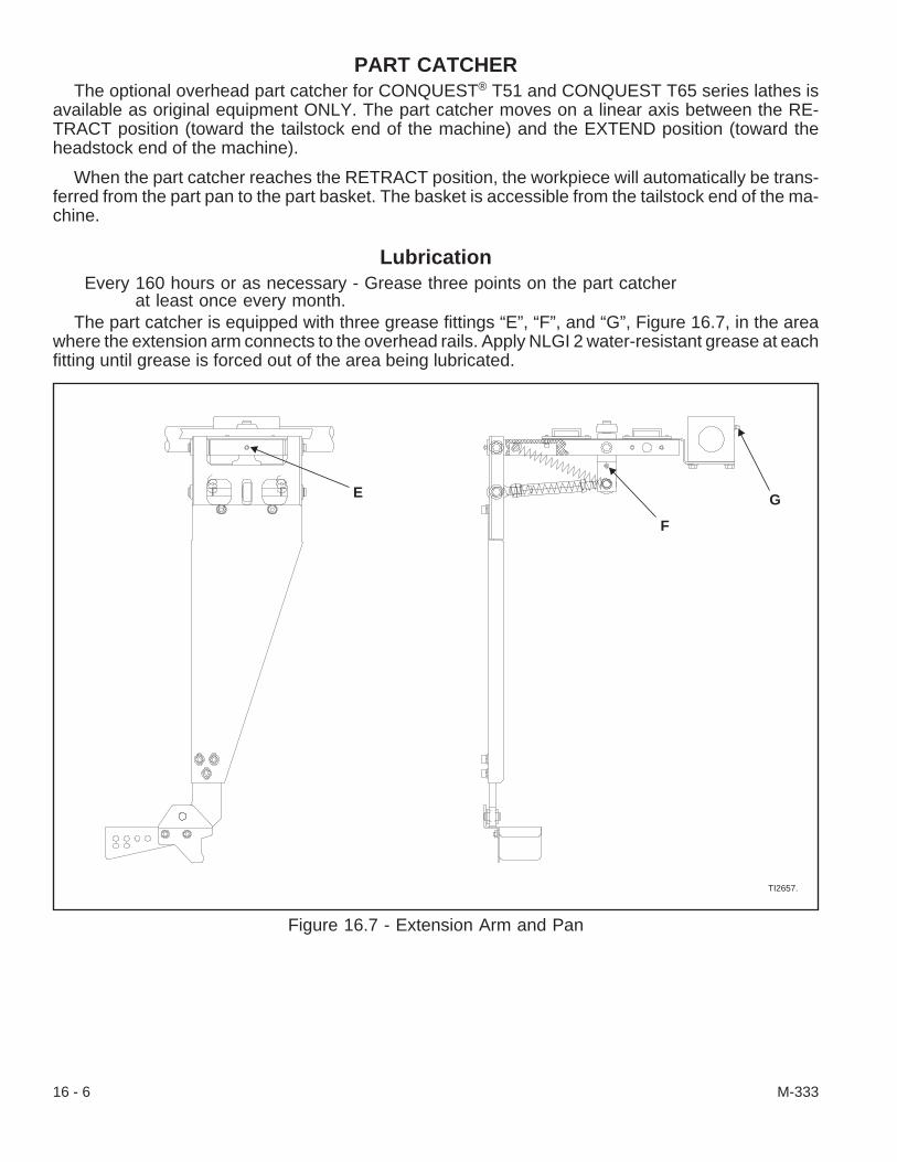
PART CATCHERThe optional overhead part catcher for CONQUEST® T51 and CONQUEST T65 series lathes is
available as original equipment ONLY. The part catcher moves on a linear axis between the RE-TRACT position (toward the tailstock end of the machine) and the EXTEND position (toward theheadstock end of the machine).
When the part catcher reaches the RETRACT position, the workpiece will automatically be trans-ferred from the part pan to the part basket. The basket is accessible from the tailstock end of the ma-chine.
LubricationEvery 160 hours or as necessary - Grease three points on the part catcher
at least once every month.The part catcher is equipped with three grease fittings “E”, “F”, and “G”, Figure 16.7, in the area
where the extension arm connects to the overhead rails. Apply NLGI 2 water-resistant grease at eachfitting until grease is forced out of the area being lubricated.
16 - 6 M-333
Figure 16.7 - Extension Arm and Pan
TI2657.
E
F
G

Every 500 hours or as necessary - Lubricate the slide rails and part pan bushingon the part catcher at least once every three months.
- WARNING -Be sure to clean all chips from the slide rails and slide packs before applying lu-brication. Personal injury may result if chips are encountered during lubrication.
To lubricate the slide rails:
1. Lock out the machine air system as follows:A. Press the Emergency Stop (E-Stop) [74]
pushbutton.B. Turn the main air valve OFF at the back
of the machine and lock it out.2. Open the coolant guard door.3. Carefully clean all chips from two slide rails “H”,
Figure 16.8.4. Apply NLGI 2 water-resistant grease the full
length of each slide rail at locations “I” and “J”.5. Close the coolant guard door.6. Enable machine operation as follows:
A. Unlock the main air valve and turn it ON.B. Turn the E-Stop [74] pushbutton clockwise
to release it.C. Press the E-Stop Reset [73] pushbutton.
To lubricate the part pan bushing:
1. Using MDI mode, move the part catcher to theforward position (M26) for easier access to thepart pan.
2. Lock out the machine air system as follows:A. Press the Emergency Stop (E-Stop) [73]
pushbutton.B. Turn the main air valve OFF at the back
of the machine and lock it out.3. Open the coolant guard door.4. Carefully clean all chips from the part pan and
the extension arm, Figure 16.9.
(continued on the next page)
M-333 16 - 7
Figure 16.8 - Slide Rail Lubrication
TI2662.
View “A”
See View “A”
H
I J
Figure 16.9 - Bushing Lubrication
TI2661.
MK
L
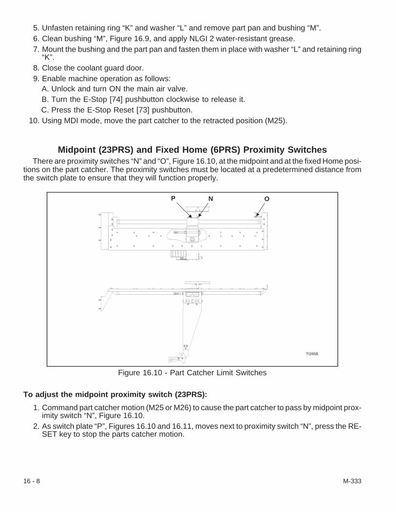
5. Unfasten retaining ring “K” and washer “L” and remove part pan and bushing “M”.6. Clean bushing “M”, Figure 16.9, and apply NLGI 2 water-resistant grease.7. Mount the bushing and the part pan and fasten them in place with washer “L” and retaining ring
“K”.8. Close the coolant guard door.9. Enable machine operation as follows:
A. Unlock and turn ON the main air valve.B. Turn the E-Stop [74] pushbutton clockwise to release it.C. Press the E-Stop Reset [73] pushbutton.
10. Using MDI mode, move the part catcher to the retracted position (M25).
Midpoint (23PRS) and Fixed Home (6PRS) Proximity SwitchesThere are proximity switches “N” and “O”, Figure 16.10, at the midpoint and at the fixed Home posi-
tions on the part catcher. The proximity switches must be located at a predetermined distance fromthe switch plate to ensure that they will function properly.
To adjust the midpoint proximity switch (23PRS):
1. Command part catcher motion (M25 or M26) to cause the part catcher to pass by midpoint prox-imity switch “N”, Figure 16.10.
2. As switch plate “P”, Figures 16.10 and 16.11, moves next to proximity switch “N”, press the RE-SET key to stop the parts catcher motion.
16 - 8 M-333
Figure 16.10 - Part Catcher Limit Switches
TI2658.
P N O

3. Lock out the machine air system as follows:A. Press the Emergency Stop (E-Stop) [74] pushbutton.B. Turn the main air valve OFF at the back of the machine and lock it out.
4. Open the coolant guard door.5. Carefully loosen outside (right) locknut “Q”, Figure 16.11, just a thread or two.
- NOTES -The switch gap specification for the distance from the tip of the proximity switch tothe switch plate is set between .035 and .045 inch [.89 and 1.16 mm]. Refer to Fig-ure 16.11.
Make certain that there is a lock washer on each proximity switch locknut.
6. Check the switch gap distance from the switchplate to the tip of the proximity switch.
7. Adjust inside (left) locknut “Q”, if necessary, un-til the specification of the switch gap is set.
8. Secure the inside locknut and tighten the out-side locknut to 60 lb-in. [6.8 N•m] torque.
9. Check the switch gap and adjust the final switchsettings as necessary.
10. Close the coolant guard door.11. Enable machine operation as follows:
A. Unlock and turn ON the main air valve.B. Turn the E-Stop [74] pushbutton clockwise
to release it.C. Press the E-Stop Reset [73] pushbutton.
12. Use the MDI mode and move the part catcher to the retracted position (M25).
To adjust the fixed Home proximity switch (6PRS):
1. Using MDI mode, move the part catcher to the retracted position (M25). Switch plate “P”, Figures16.10 and 16.11, will be positioned next to Home proximity switch “O”, Figure 16.10.
2. Lock out the machine air system as follows:A. Press the Emergency Stop (E-Stop) [74] pushbutton.B. Turn the main air valve OFF at the back of the machine and lock it out.
3. Open the coolant guard door.4. Carefully loosen outside (right) locknut “Q”, Figure 16.11, just a thread or two.
(continued on the next page)
M-333 16 - 9
Figure 16.11 - Limit Switch Adjustment
.035 - .045 inch[.89 - 1.14 mm]
Q TI2659
P

- NOTES -The switch gap specification for the distance from the tip of the proximity switch tothe switch plate is set between .035 and .045 inch [.89 and 1.14 mm]. Refer to Fig-ure 16.11.
Make certain that there is a lock washer on each proximity switch locknut.
5. Check the switch gap distance from the switch plate to the tip of the proximity switch.6. Adjust inside (left) locknut “Q”, if necessary, until the specification of the switch gap is set.7. Secure the inside locknut and tighten the outside locknut to 60 lb-in. [6.8 N•m] torque.8. Check the switch gap and adjust the final switch settings as necessary.9. Close the coolant guard door.
10. Enable machine operation as follows:A. Unlock and turn ON the main air valve.B. Turn the E-Stop [74] pushbutton clockwise to release it.C. Press the E-Stop Reset [73] pushbutton.
To replace and adjust the switches:
1. Move the part catcher to a convenient work position away from either switch being replaced.2. Power down the machine. Make certain that the air valve is turned OFF and locked out.3. Open the coolant guard door.4. Refer to Figure 16.10 and tag each proximity switch for re-assembly.5. Measure the distance from the bracket to the tip of the switch for approximate replacement loca-
tion.6. Carefully unthread the locknuts and remove the switch(es) from the bracket.7. Use a lock washer with each locknut on the switch, install the switch on the bracket, and set the
length per the distance from step #5 above.8. Unlatch the Input/Output (I/O) case door in two places and open the door. Follow cable 107 from
the midpoint proximity switch or cable 18 from the fixed Home proximity switch into the I/O case.9. Route the cable from the replacement switch(es) into the I/O case.
16 - 10 M-333

10. Connect the wire(s) for the new switch(es) as follows:A. Check the switch wire connections against the connections listed below. Make notes of
any changes as necessary.Terminal Block Connections:
23PRS (midpoint reference) - Cable 107Red Wire to 4TB10
Blk Wire to 14TB14
6PRS (fixed Home) - Cable 18Red Wire to 4TB10
Blk Wire to 14TB15
B. Disconnect the wires from the terminal block connections.C. Connect the wires to the terminal block connections per step A, above.D. Close and latch the I/O case door.
11. Adjust the new switch(es) as follows:A. Power up the machine.B. Move the switch plate in front of the midpoint proximity switch or back to the fixed Home
proximity switch so that the final switch gap for the switch being replaced can be set.C. Lock out the machine air system.D. Open the coolant guard door.
- NOTE -The switch gap specification for the distance from the tip of the proximity switch tothe switch plate is set between .035 and .045 inch [.89 and 1.14 mm]. Refer toFigure 16.11.
E. Check the switch gap distance from the switch plate to the tip of the proximity switch.F. Adjust locknut “U”, if necessary, until the specification of the switch gap is set.G. Secure locknut “U”, and tighten locknut “T”, to 60 lb-in. [6.8 N•m] torque.H. Check the switch gap and adjust the final switch settings as necessary.
12. Close the coolant guard door.13. Enable machine operation as follows:
A. Unlock and turn ON the main air valve.B. Turn the E-Stop [74] pushbutton clockwise to release it.C. Press the E-Stop Reset [73] pushbutton.
14. If the midpoint proximity switch was replaced, then use the MDI mode and move the part catcherto the retracted position (M25).
M-333 16 - 11

Extend (2A Sol) and Retract (2B Sol) Solenoid ValvesThe solenoid valves are horizontally stacked on the air panel at the back of the machine.
To replace a part catcher solenoid valve:
1. Power down the machine. Make certain that the air lock out valve is OFF and locked out.2. Refer to the schematic chart on the panel to identify which valve needs to be replaced.3. Unthread the screw and remove the end plate from the stack of solenoid valves.4. Unscrew the two fasteners that mount the end cap and each valve to its adjacent valve until the
valve to be replaced is removed or until the new valve can be added to the stack of valves.
- NOTE -Do not remove the electrical connection or air line from the valves that are notbeing replaced.
5. Unthread the screw that secures the electrical connection to the solenoid valve being replaced.Pull the connection straight up to release it from the valve.
6. Unthread the air line from the fitting on the bottom of the valve being replaced. If necessary, re-move the pneumatic fitting from the valve.
7. Thread the air fitting to the new valve. Use sealant to secure the fitting but do not apply it to thefirst few threads.
8. Mount the new valve to the end piece or adjacent valve on the panel. Check the valve gasketsand replace any that are worn. Fasten each valve and gasket in place.
9. Check the gaskets and mount the other valves and end plate to the new valve.10. Support the new valve and fit the electrical connection to it. Secure the connection with its screw.11. Fasten the air line to the fitting on the bottom of the valve.12. Power up the machine. Set the regulator to an operating pressure between 80 and 90 psi [5.5
and 6.3 bars].13. Zero Return (Home) the axes. Press the E-Stop Reset [73] pushbutton if it is still necessary to
clear “1017 Main Air Pressure Low” alarm message from the CRT.14. Check the air system bowl for contamination, moisture, or air leaks and correct any problems as
necessary.Test the function of the part catcher and adjust it as necessary.
16 - 12 M-333

- NOTES -
M-333 16 - 13

- NOTES -
16 - 14 M-333
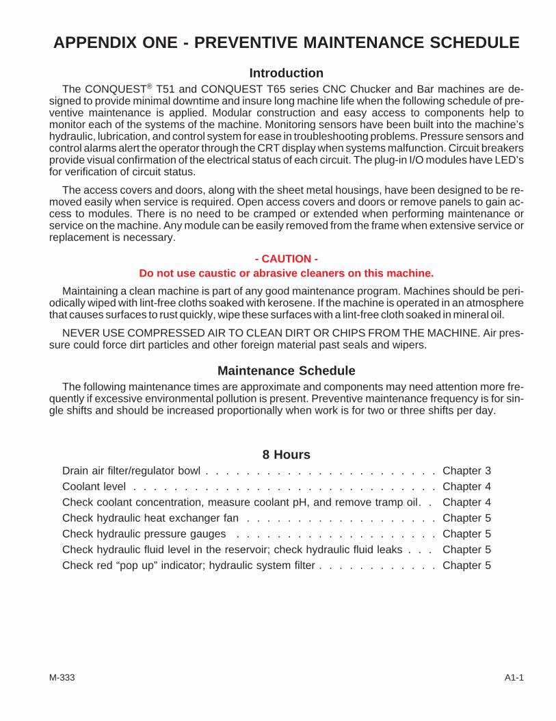
APPENDIX ONE - PREVENTIVE MAINTENANCE SCHEDULE
IntroductionThe CONQUEST® T51 and CONQUEST T65 series CNC Chucker and Bar machines are de-
signed to provide minimal downtime and insure long machine life when the following schedule of pre-ventive maintenance is applied. Modular construction and easy access to components help tomonitor each of the systems of the machine. Monitoring sensors have been built into the machine’shydraulic, lubrication, and control system for ease in troubleshooting problems. Pressure sensors andcontrol alarms alert the operator through the CRT display when systems malfunction. Circuit breakersprovide visual confirmation of the electrical status of each circuit. The plug-in I/O modules have LED’sfor verification of circuit status.
The access covers and doors, along with the sheet metal housings, have been designed to be re-moved easily when service is required. Open access covers and doors or remove panels to gain ac-cess to modules. There is no need to be cramped or extended when performing maintenance orservice on the machine. Any module can be easily removed from the frame when extensive service orreplacement is necessary.
- CAUTION -Do not use caustic or abrasive cleaners on this machine.
Maintaining a clean machine is part of any good maintenance program. Machines should be peri-odically wiped with lint-free cloths soaked with kerosene. If the machine is operated in an atmospherethat causes surfaces to rust quickly, wipe these surfaces with a lint-free cloth soaked in mineral oil.
NEVER USE COMPRESSED AIR TO CLEAN DIRT OR CHIPS FROM THE MACHINE. Air pres-sure could force dirt particles and other foreign material past seals and wipers.
Maintenance ScheduleThe following maintenance times are approximate and components may need attention more fre-
quently if excessive environmental pollution is present. Preventive maintenance frequency is for sin-gle shifts and should be increased proportionally when work is for two or three shifts per day.
8 HoursDrain air filter/regulator bowl . . . . . . . . . . . . . . . . . . . . . . . Chapter 3Coolant level . . . . . . . . . . . . . . . . . . . . . . . . . . . . . . Chapter 4Check coolant concentration, measure coolant pH, and remove tramp oil. . Chapter 4Check hydraulic heat exchanger fan . . . . . . . . . . . . . . . . . . . Chapter 5Check hydraulic pressure gauges . . . . . . . . . . . . . . . . . . . . Chapter 5Check hydraulic fluid level in the reservoir; check hydraulic fluid leaks . . . Chapter 5Check red “pop up” indicator; hydraulic system filter . . . . . . . . . . . . Chapter 5
M-333 A1-1
40 HoursRemove chips from coolant reservoir . . . . . . . . . . . . . . . . . . . Chapter 4Check oil level in lubrication reservoir; check tramp oil pan. . . . . . . . . Chapter 6Remove, clean, and lubricate draw tube . . . . . . . . . . . . . . . . . Chapter 8(Draw tube should also be cleaned between job set-ups.)Clean fan air filters . . . . . . . . . . . . . . . . . . . . . . . . . . . Chapter 15Check circulating fans for dirt and proper operation. . . . . . . . . . . . Chapter 15Wash machine and wipe clean . . . . . . . . . . . . . . . . . . . . Appendix One
160 HoursCheck and clean air line filter . . . . . . . . . . . . . . . . . . . . . . Chapter 3
500 HoursCheck spindle drive belt for wear and tension. . . . . . . . . . . . . . . Chapter 7Check spindle encoder timing belt for wear and tension . . . . . . . . . . Chapter 7Inspect spindle brake . . . . . . . . . . . . . . . . . . . . . . . . . . Chapter 7
1000 HoursClean and flush coolant system and change coolant . . . . . . . . . . . Chapter 4(Coolant reservoir should also be cleaned when changing the type or brand of coolant.)(Follow coolant manufacturer’s recommendations.)Clean and refill hydraulic system . . . . . . . . . . . . . . . . . . . . . Chapter 5Check hydraulic hoses for cracks, bad fittings, and kinks. . . . . . . . . . Chapter 5Check hydraulic system accumulator precharge. . . . . . . . . . . . . . Chapter 5Check hydraulic system wiring for deterioration; check LED’s . . . . . . . Chapter 5Clean lubricant reservoir . . . . . . . . . . . . . . . . . . . . . . . . . Chapter 6Replace lubricator filter (in spindle compartment) . . . . . . . . . . . . . Chapter 6Check the lubricator divider valves (feeders) . . . . . . . . . . . . . . . Chapter 6Remove and lubricate collet closer. Check brake disc . . . . . . . . . Chapters 7, 8
4000 HoursClean hydraulic system reservoir and change hydraulic oil . . . . . . . . . Chapter 5Replace hydraulic pump intake filter . . . . . . . . . . . . . . . . . . . Chapter 5(Also replace if red “pop-up” indicator is extended)Check seal on hydraulic reservoir filler cap . . . . . . . . . . . . . . . . Chapter 5Install a fresh control back-up battery . . . . . . . . . . . . . . . . . . Chapter 16(Hardinge Inc. recommends installing a fresh battery each 2000 hours)Install a fresh end-working turret option control battery . . . . . . . . . . Chapter 16(Hardinge Inc. recommends installing a fresh battery each 2000 hours)
A1-2 M-333
Maintenance Schedule of Hardinge Options
8 HoursApply grease to the steady rest (recommended every 4 to 8 hours of operation).Check barfeed oil levelCheck oil level in T65-L tailstock air lubricatorClean chips from tool probeClean chips from part catcherClean tool touch probeGrease chuck master jawsGrease live tooling holders
40 HoursClean chip conveyorClean sub-spindle draw tube wiper and sub-spindle boreLubricate overhead part catcherLubricate sub-spindle part catcher
160 HoursDisassemble and clean chuck
1000 HoursCheck warning lightsCheck barfeed-in-position switchTighten electrical plug connections in power case, I/O case, and control caseCheck and fill chip conveyor gearbox oilCheck and adjust chip conveyor drive belt tension
4000 HoursInstall a fresh end-working turret option control battery(Hardinge Inc. recommends installing a fresh battery each 2000 hours)
M-333 A1-3

- NOTES -
A1-4 M-333
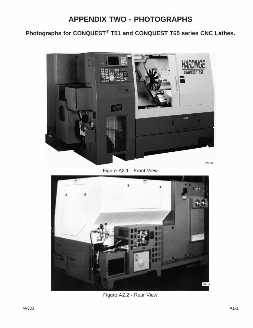
APPENDIX TWO - PHOTOGRAPHS
Photographs for CONQUEST® T51 and CONQUEST T65 series CNC Lathes.
M-333 A1-1
Figure A2.1 - Front View
TP2141.
Figure A2.2 - Rear View
TP433.

A - Lubrication Unit
B - Control Case
C - Spindle Drive Compartment
D - Spindle Draw Tube Access Cover
E - RS232 Serial Port (covered)
F - Power Case (Plenum) Fan
A1-2 M-333
Figure A2.3 - Left End View (Spindle Drive Compartment)
TP434.
B
E
D
C
AF

A - Incoming Power Distribution
B - Power Supply for Survo
C - Axes Servo Drives
D - Spindle Servo (Drive) Unit
E - 24v Power Supply and Terminal Strip
F - 115v Transformer
G - Line Reactor
M-333 A1-3
Figure A2.4 - Power Case
TP661.
B
C
A
D
EF G
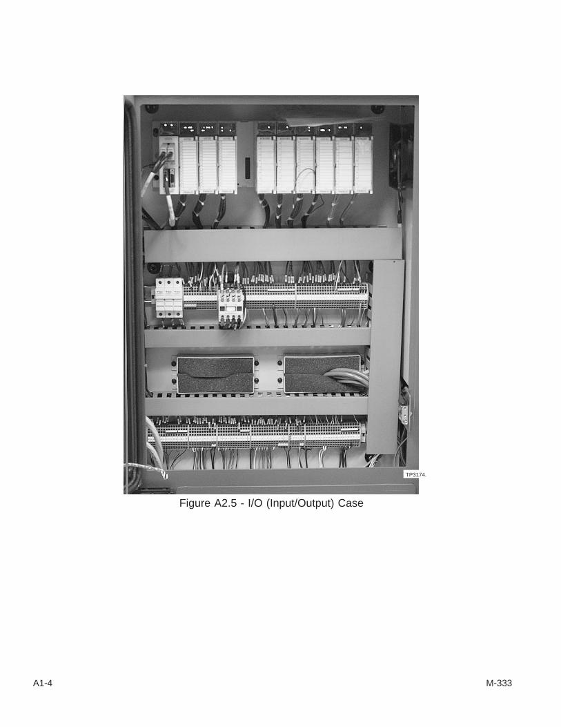
A1-4 M-333
Figure A2.5 - I/O (Input/Output) Case
TP3174.

B - 1FU-1
C - 1FU-2
D - 1FU-3
E - 1CB (Main Circuit Breaker)/Fuse Holder
M-333 A1-5
Figure A2.6 - Main Disconnect Switch
TP451.
A
A - Main Disconnect Switch(On power case door)
Figure A2.7 - Main Disconnect Switch(Inside Power Case)
TP661.
B C D
E
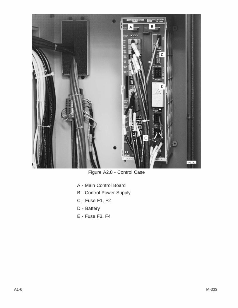
A - Main Control Board
B - Control Power Supply
C - Fuse F1, F2
D - Battery
E - Fuse F3, F4
A1-6 M-333
Figure A2.8 - Control Case
TP3160.
C
E
B
D
A
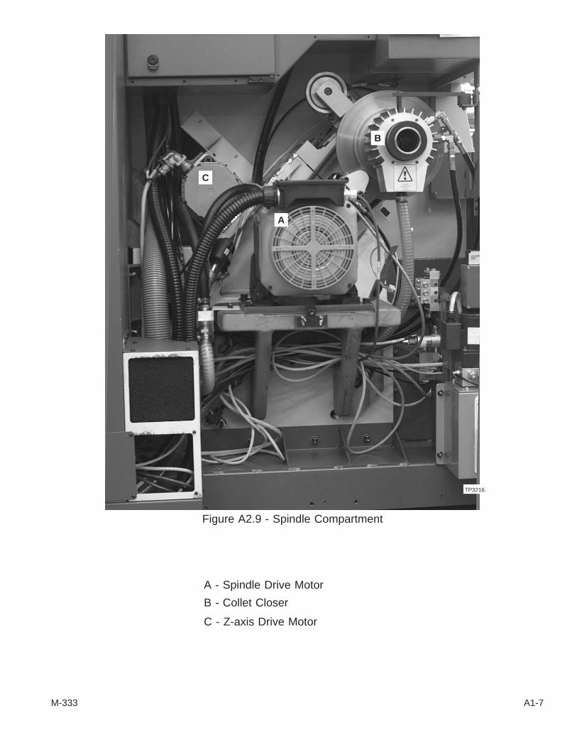
A - Spindle Drive Motor
B - Collet Closer
C - Z-axis Drive Motor
M-333 A1-7
Figure A2.9 - Spindle Compartment
A
C
B
TP3216.

A - Sensors
B - Magnetic Ring
Pre-amplification boxes are mounted in the spindle compartment.
A1-8 M-333
Figure A2.10 - "C" Axis Sensor Unit on Spindle
TP450.
A
B A

- NOTES -
M-333 A1-9

“Performance Has Established Leadership for Hardinge”®
Hardinge Inc.Elmira, New York 14902-1507 USA
Phone: 607-734-2281 Fax: 607-734-8819www.hardinge.com