
MAINTENANCE HANDBOOK ON ROUTE RELAY ......relay groups are also used, so that during route setting,...
73
Hkkjr ljdkj &GOVERNMENT OF INDIA jsy ea=ky;& MINISTRY OF RAILWAYS ¼dk;kZy;hu iz;ksx gsrq½& (For official use only) MAINTENANCE HANDBOOK ON ROUTE RELAY INTERLOCKING (Metal to Metal Relays) CAMTECH/S/PROJ/2015-16/MHB-RRI-MM/1.0 FEBRUARY 2016 MAHARAJPUR, GWALIOR – 474 005
Transcript of MAINTENANCE HANDBOOK ON ROUTE RELAY ......relay groups are also used, so that during route setting,...

Hkkjr ljdkj &GOVERNMENT OF INDIA jsy ea=ky;& MINISTRY OF RAILWAYS ¼dk;kZy;hu iz;ksx gsrq½& (For official use only)
MAINTENANCE HANDBOOK
ON
ROUTE RELAY INTERLOCKING (Metal to Metal Relays)
CAMTECH/S/PROJ/2015-16/MHB-RRI-MM/1.0
FEBRUARY 2016
MAHARAJPUR, GWALIOR – 474 005

CONTENTS
Sr.No. Description Page No. Foreword ii
Preface iv
Correction Slips vi
Contents viii
1. Introduction 1 2. Sequence of Relay Operation 4 3. Major Point Group 11 4. A.C. 3 Phase 380 Volt Point Machine 31 5. Siemens Point Chain Relay Group 36 6. Control of Other Than Siemens Point Machine With Siemens Point Switching Relay Group 37 7. Control of Siemens Point Machine Without Using Point Group 40 8. Semi Automatic Signals in RRI (Siemens) 47 9. Power Supply Arrangement with L.T. Panel 53 10. Do’s & Don’ts 62 11. Trouble Shooting of RRI & PI 63 12. Reference

CONTENTS
Sr.No. Description Page No.
1. Introduction 1 2. Sequence of Relay Operation 4 3. Major Point Group 12 4. A.C. 3 Phase 380 Volt Point Machine 34 5. Siemens Point Chain Relay Group 38 6. Control of Other Than Siemens Point Machine With Siemens Point Switching Relay Group 39 7. Control of Siemens Point Machine Without Using Point Group 42 8. Semi Automatic Signals in RRI (Siemens) 49 9. Power Supply Arrangement with L.T. Panel 55 10. Do’s & Don’ts 64 11. Trouble Shooting of RRI & PI 65

ISSUE OF CORRECTION SLIPS
The correction slips to be issued in future for this handbook will be numbered as follows:
CAMTECH/S/PROJ/2010-11/HB-RRIS/1.0/C.S.# XX date-------------------------------- Where “XX” is the serial number of the concerned correction slip
(starting from 01 onwards)
CORRECTION SLIPS ISSUED
Sr. No. of
Corr. Slip
Date of
issue
Page No. and Item no.
modified
Remarks

Reference
1. Secunderabad IRISET Notes. 2. Training Package on Route Relay Interlocking(Metal to Metal)/2001.

CAMTECH/S/PROJ/2015-16/MHB-RRI_MM/1.0 1
Route Relay Interlocking (Metal to Metal relays) February 2016
ROUTE RELAY INTERLOCKING (Metal to Metal relays)
1. INTRODUCTION 1.1. Route Setting type Relay Interlocking (Route Relay Interlocking) system is
adopted for major and junction stations and Non-Route setting (Panel Interlocking) for smaller and way side stations.
The only difference of Siemens Route Relay Interlocking with respect to Siemens Panel Interlocking is that it has the additional facility to set the points on the route, overlap and isolation automatically when a route is initiated. Major point relay groups are used in this system (Minor point relay groups are used in Non Route Setting type). In addition, point chain relay groups are also used, so that during route setting, all the required point machines of points on the route/overlap/isolation are switched one after another and not simultaneously. Thus, heavy drawl of current from the battery for simultaneous starting of more than one point is avoided. Details of Siemens Major Point Relay Group, Point Chain Relay Group, Point Switching Relay Group and Siemens Electric Point Machine (110V DC and 380 V AC 3 Phase) are given in this book. In addition, the installation and testing practices to be followed for Siemens Relay Interlocking System also are explained here. All the required drawings of a two-line station with Siemens Route Relay Interlocking System are given in this book. They include signaling plan, Route section plan, table of control, wiring diagrams and contact analysis.
1.2. ESSENTIAL Of ROUTE RELAY INTERLOCKING :
Following principles have been adopted in the design of circuits using metal to metal relays (K-50 relays).
1. Any unsafe failure can only result in prohibition and not in a permission. 2. Each failure should draw the attention of the operator by withholding a
permission, which could otherwise be given. 3. The correct completion of an action, which has been initiated, must be
confirmed by an active indication. 4. Every indication, which might result in permission, must take the form of
an action. e.g. the current energizing a relay during the time the permission is effective in case of a neutral relay and the pulse changing the position of an interlocked relay.
5. Dependent actions should be switched in cascade via the indication. i.e. the initiation of an action is identical with the indication of previous action.
6. Independent actions may take place at the same time if indication of their correct completions are switched in series.
7. Continuous indications must be interrupted during each working cycles to

CAMTECH/S/PROJ/2015-16/MHB-RRI_MM/1.0 2
Route Relay Interlocking (Metal to Metal relays) February 2016
prove that the indicating device is capable of work and the information is the result of an action.
8. The final permission for a signal to be cleared must be obtained by the
energisation resulting from two independent actions. 9. The proper functioning of the track relay should be checked in route
release circuits. The circuit is so designed that two buttons must always be operated
simultaneously. The main advantages of both hand operation are : 1. Accidental operation of a single push button will have no effect. 2. The setting up of a route takes place only when both entrance and exit
buttons are actuated simultaneously. This makes the arrangements of buttons on the penal particularly clear and their functions comes naturally to the mind. The operator can find the correct buttons without the reading indicating labels or other inscriptions.
3. Power buttons are required on the panel, e.g. there is only one button for each point ( Whether single ended or cross over). If this pressed with a common group button for points, the point will change over to the other position.
1.3. IN ROUTE RELAY SYSTEM 1. By pressing signal and route button, route will set, point will be operated
to required position, point will be locked, route will be locked and signal will clear.
2. After the passage of train, route will be unlocked, point will be unlocked and then point can be operated to other position.
3. Conflicting signal movements can not be initiated before the completion of previous signaled move.
4. Points can be operated independently and in case the point is not operating after the route is set.
5. After the clearance of a signal, SM can cancel the signal route including overlap with time lag.
6. Overlap also can be cancelled by SM if required with time lag. 7. Route can be cancelled by SM with the co-operation of S&T staff. VARIOUS RELAYS USED IN ROUTE RELAY INTERLOCKING 1. Signal group For signal clearance 2. Shunt signal group For shunt signal clearance 3. Route group To operate & lock the point & lock the route 4. Point group For operating the point & giving indication 5. Point chain group To operate the points in sequence when route is set 6. Interlocked relay To retain in the last operated position

CAMTECH/S/PROJ/2015-16/MHB-RRI_MM/1.0 3
Route Relay Interlocking (Metal to Metal relays) February 2016
7. Neutral relay 8. Lamp proving relay 9. Time relay
10. Flasher relay CNTROL & INDICATION PANEL
Control (Operating) panel consists of various buttons for operating signals, points & emergency operation buttons at an inclined position to have easy operation. Indication panel will be vertical and entire yard position will be exactly reproduced.
VARIOUS BUTTONS WITH COUNTER 1. EWZ Emergency point operation counter 2. EUUYZ Emergency route cancellation counter (by SM) 3. EUYZ Emergency sub route cancellation counter 4. COOGZ Calling on signal clearance counter 5. OYZ Emergency over lap can collation counter ( by SM) 1.3. Difference between Panel interlocking and Route relay interlocking (SIEMENS)
Sr. No
PANEL R.R.I
1 Point group is Minor Point group is major
2 Points in the route, overlap and isolation are operated individually before signal and route are operated
Setting of all points in the route, overlap and isolation and also clearing the signal is achieved by one operation of pressing the concern GN & UN buttons.
3 NWKR/RWKR are normally energized NWKR /RWKR are normally de-energized, picks up only when route setting is done.
4 Before any point could be operated, it should be ensured that all relevant route sections, overlap is in normal position.
Point setting is done by concern U(R) S, OV Z2U(R) R. The locking provided for various stages takes care of this.
5 This is confined to smaller yards and suitable for way-side stations.
Suitable for major yards with heavy shunting or on busy suburban sections.
6 Only two types of electrical lockers are provided i) Individual point locking U(R)S (ii) Full route locking by UR(L)R
Locking actions are many
7 The function of WR(L)R and UR(L)R is done by U(R)S.
Point locking is done by WR(L)R and individual sub route locking by UR(L)R
8 Route setting relays U(R)S, over lap setting relay OVZ2U(R)R are meant for locking the points .
U(R)S &OVZ2U(R)R relays are meant for operating the points.
9 Irrespective of whether the move is for shunt or main signal, sub route locking is achieved by U(R)S
Sub route locking is done by UR(L)R for main signal move, and U(R)S for shunt move.

CAMTECH/S/PROJ/2015-16/MHB-RRI_MM/1.0 4
Route Relay Interlocking (Metal to Metal relays) February 2016
10 Point chain group is not necessary. Suitable instructions are incorporated in SWR not to operate more than two points at a time
Point chain group is necessary.
11 Presetting setting of route is essential for the pick up of GLSR
Setting of route is not compulsory for the picking up of GLSR
12 U(R)S requires the points in the route to the required position, hence NWKR or RWKR required for A U(R)S or B U(R)S
U(R)S changes the points to the required position by initiating the point group. Also does not allow the points to be unlocked unless the route is released. WR(L)R locking in addition to the UR(L)R locking
2. SEQUENCE OF RELAY OPERATIONS 2.1. The circuitry in this system is broadly classified as: a) Route and Signal Initiation circuits. b) Sub-route, overlap setting and locking circuits. c) Points control, detection and locking circuits. d) Signal clearance circuits e) Route release circuits: – Automatic and manual cancellation circuits. f) Emergency sub route cancellation circuits. 2.2. The sequence of relays operation for different circuit is discussed below
with the help of block diagrams.
2.2.1. Sequence of relay Operation for Signal Clearance:

CAMTECH/S/PROJ/2015-16/MHB-RRI_MM/1.0 5
Route Relay Interlocking (Metal to Metal relays) February 2016

CAMTECH/S/PROJ/2015-16/MHB-RRI_MM/1.0 6
Route Relay Interlocking (Metal to Metal relays) February 2016
For setting a route entrance and exit buttons are depressed simultaneously. Their button relays operate and establish the direction of traffic movement by operating the relevant direction-determining relay ZU(R/N)R. Simultaneously if shunt signal is there in a route then main signal/shunt signal selection relay Sh G(R/N) R relay operates and selects the signal.
Each sub route is initiated in a signal route in cascade commencing from the first sub-route, i.e. Z1UR relays of all sub-routes in the route are operated in succession. This relay operates for both straight and diverging route section movements. In RRI diversion selector relay Z1UR1 of all the sub routes in the route requiring the point in Reserve position operates. Proving all Z1URs and Z1UR1s picked up and other interlocking conditions, Mn GZR or Sh GZR picks up and then ZDUCR relay picks up.
ZDUCR relay with concern Z1UR relay switches on route group by picking up relevant U(R)S relay. This relay initiates point group relays for setting the points to the required position in the sub route and isolation points if any. When the point in the sub route is correctly set and detected, the clear route-checking relay A/B DUCR picks up. The sub route-locking relay U(R) LR operates after ensuring the points in the sub-route are correctly set, detected and on release of the signal and route buttons to lock the sub route electrically. In this manner all the sub route in the signal route are set, checked and locked.
Main GZR relay with ZDUCR relay and concern button relay, switches on relevant overlap setting relay OVZ2U(R) R and this relay initiates operation of point group relays in the over lap and locks the same. If it is in the required condition it locks the point groups electrically in overlap.
The signal clearance in accordance with the requirements specified in IRSE manual. The final permission for signal clearance is given by two independent energisation i.e., two relays are used for clearing a signal (Red to Yellow). The first relay GR1 operates proving that all sub routes are set, checked and locked. Isolation points and over lap is clear. To achieve one operation one movement a signal lock stick relay (GSLR) is employed. This GLSR relay normally remains de-energized and picks up when the route is initiated and drops before the second signal control relay (GR2) is operating to clear a signal. In case of shunt signal this relay is normally energized and drops when the signal button is released. GR1 operating energizes the junction indicator lamps for diverging routes and initiates locking of all other signal leading towards that berthing track for which the signal control relay No.2 (GR2) operates.

CAMTECH/S/PROJ/2015-16/MHB-RRI_MM/1.0 7
Route Relay Interlocking (Metal to Metal relays) February 2016
2.2.2. Sequence of relay operation for Automatic Route Release
Note: 1. Track Power Supply availability must be proved. 2. The Occupation of Berthing Track must be proved in the release circuit of Last Sub- Route.

CAMTECH/S/PROJ/2015-16/MHB-RRI_MM/1.0 8
Route Relay Interlocking (Metal to Metal relays) February 2016
Automatic Route Release after the passage of train is controlled by UYR1,
UYR2, UDKR and Sig. RE(Mn)CR. 2.2.3. Sequence of relay operation for Automatic Overlap Release 1. Without any Time Delay : 2.2.4. Sequence of relay operation for Emergency Full Route Cancellation 2. To Replace the Signal to “ON”
LAST SUB-ROUTE
U(N)S

CAMTECH/S/PROJ/2015-16/MHB-RRI_MM/1.0 9
Route Relay Interlocking (Metal to Metal relays) February 2016
3. When there is A Train ‘ON APPROACH’
After Replacing the Signal to ‘ON’ as in 1. Press ‘GN’ and ‘EUUYN’ Simultaneously and release.
Once the white Dot indication become Steady, Press ‘GN’ and ‘EUUYN‘ Simultaneously. Release ‘EUUYN’ keeping ‘GN’ Pressed and Press ‘UN’ as in (2) above
Sequence of Relay Operation is same as in (2).
The White Dot indication is Called as “APPROACH LOCK INDICATION”.
Emergency Sub-Route Cancellation (By EUYN Key.) 2.2.5. Sequence of Relay Operation
“This Cancellation facility Should be used only when automatic Route release as well as Emergency Full route Cancellation has failed “. The individual sub-route cancellation has been effected by Pressing ‘EUYN’ and nominated point button WN with White Dot on top for that sub-route.

CAMTECH/S/PROJ/2015-16/MHB-RRI_MM/1.0 10
Route Relay Interlocking (Metal to Metal relays) February 2016
2.2.6. Sequence of Relay Operation for “Calling ON Signal” Clearance: First set the Point in the required position. When the Train has occupied the Approach Track, Press ‘GN’ and ‘COGGN’ Simultaneously, release ‘COGGN’ Keeping ‘GN ‘ pressed and press ‘UN’ .

CAMTECH/S/PROJ/2015-16/MHB-RRI_MM/1.0 11
Route Relay Interlocking (Metal to Metal relays) February 2016

CAMTECH/S/PROJ/2015-16/MHB-RRI_MM/1.0 12
Route Relay Interlocking (Metal to Metal relays) February 2016
3. MAJOR POINT GROUP 3.1. Major Point Relay Group:
Major point group consist of 5 interlocked relays, 13 neutral relays and one contactor relay. In addition three lamp indications are provided
The major Point relay group is used only in Route Relay Interlocking. This unit accommodates 5 interlocked relays, 13 neutral relays and a contactor relay. There are three indication lamps in it. The fist lamp is a yellow lamp, which lits steady normally when the points are correctly set, locked, detected and is in correspondence with the point group.
During operation of points, or faulty condition of points, it flashes. The middle indication (red) lits steady when the point group is involved in a route set, as points in route, overlap or isolation. It flashes when the group
initiation fails under route setting condition if initiation stops with Z1WR
and WLR or with both the relays alone operated. The third red indication lits when point zone track circuit is occupied or failed.
The major point relay group operates the point during automatic route setting and individual point operation.
Under route setting condition, the point group can get operated automatically if the point fails in the route, overlap or isolation. In case of individual point operation, pressing of WWN and WN or EWN and WN operate the point group.
3.2. Relays and their functions
Z1WR : This is the first relay to operate in the point group, under route initiation to operate a point in the route, overlap or isolation. It is a K-50 ‘B’ type relay with two coils, but only one coil is being used. U(R)S, UZ4R or OVZ2(R)R
can operate Z1WR relay provided point detection is available (WKR1). If a point is flashing during initiation of a route, the point will not get initiated. In this case individual point operation has to be resorted to. Z1WR will drop only when the point group is initiated and dropping of WKR1 proves it.
Z1WR1:
This is also a K-50 B type relay having pick up and holds coils. It is the first relay to pick up in the point group during individual operation of points and is the third relay to operate under route initiation. Pick up coil to operate; it checks up that all the NWKRs and RWKRs in released condition, thus ensuring that the points are free to be operated. Once W(R)R is operated, the holding coil gets energized and hold the relay, till WR is operated.

CAMTECH/S/PROJ/2015-16/MHB-RRI_MM/1.0 13
Route Relay Interlocking (Metal to Metal relays) February 2016
WLR : This is a K-50 B type relay with two coils, called pick up and hold coils. This relay is the second relay to operate in the point group during route initiation. The very function of this relay is to ensure that, mere picking of Z1WR will not operate the point group, but only through a positive route
initiation. WLR checks the following indications ZDUCR, Z1UR1, TPR,
Z1WRand W(R)R. Once operated it holds through its own F/C and WKR2 B/C. This relay also switches on point chain group relay WWR.
Z1NWR & Z1RWR : These have two coils each, pick up and hold coils. These relays switches on (R) I (N) WLR1, (R) I (N) WLR2, and (R) I (N) WLR3. When the (R/N) WLR3, picks up, it short circuits Z1NWR/Z1RWR hold coil through a
resistance of 220 The pick up coil gets de-energized when WLR or WWR are dropped in case of route initiation and dropping of WNR for individual point operation. Unless Z1NWR/Z1RWR drops, further sequence of relay operation in the point button is released before the point could start operating.
WKR1:
This is the Point detection relay. (Coil resistance 1840 , Pick up current — 17-19 ma and normal working current — 27-28 ma). Normally remains in energized condition proving that points are correctly set, locked and detected and are in correspondence with point group. The detection current passes through WKR2 coil and all the four conductors and WKR1
coil. WKR1 contact together with (N)WLR / (R)WLR give corresponding point indication in the panel.
W(R/N)R: This relay facilitates Super imposed detection. W(R)R is energized for point operation and W(N)R is picked up for detection. During group initiation, W(R)R picks up when WKR1 is dropped. W(R)R energisation causes the interruption in feed to Z1WR1 pick up coil at the same time, through W(R)R F/C, WR B/C and Z1WR1 F/C holding coil is brought into use, and the relay Z1WR1, drops only when WR is energized.
(R/N) WLR1, 2, 3. : For operating a point from ‘N’ to ‘R’, Z1RWR energizes and cause latching of(R) WLR1,2 & 3. For setting to normal Z1NWR operates and latches (N)WLR1, 2 & 3. Even though normal and reverse operations are initiated by Z1NWR and Z1RWR, they drop prior to point operation. They only register the operation command by latching (R/N) WLR relays. Moreover, point operation circuit, it is not advisable to use neutral Relay contacts, hence the relevant latch relays (R /N) WLR contacts only are used in point control circuits. The point correspondence and detection circuit prove these relay contacts.
W(R/N)LR : This is the Point group lock relay. When a point falls in the route/overlap/isolation, W(R)LR picks up and locks the point group electrically. Lighting the middle indication on the point relay group and on

CAMTECH/S/PROJ/2015-16/MHB-RRI_MM/1.0 14
Route Relay Interlocking (Metal to Metal relays) February 2016
the panel indicates this. W(R)LR to operate, WKR1 must be up and also U(R)S / UZ4R / OVZ2(R)R must be up. NWKR I RWKR picks up only after W(R)LR operate. WKR2: This relay indicates out of correspondence of points and point relay group. Normally it remains in de-energized state. During point detection, this relay comes in series with WKR1. Since the relay coil resistance being
low (52.3 ), it requires a current of about 120 ma to energize. While point under detection the current flowing is only about 27 ma. Hence, WKR2
cannot pick up. WKR2 also provide cross protection. WKR2 operates under following conditions: 1. During point operation. 2. With more than one earth fault on conductors. 3. Whenever point remains out of correspondence. WKR2 once picked up, holds through its stick path and de-energizes WKR1. This will cause red and white flash indication at the point configuration on the control panel. WJR: This is the Over load Protection Relay — Motor used in point machines are series wound high, torque motors, duration of its working shall be less, otherwise can cause permanent damage to motor. In order to provide protection during point obstruction. This relay controls the feed to the point motor for about 10 to 15 seconds. During reverse to normal operation WJR is made to pick up in succession to Z1WR1 to de-energize WKR1. Z2WR1 & Z2WR2: These relays are used for giving point strip indication on the panel. Whenever a point is involved as a point in the route or overlap, Z2WR1 or Z2WR2 picks up to give strip indication for a more important move. TP1R — TP1P2R : These are repeaters of point zone track relays. Through these relays contacts the track locking as well as occupation and clearance indications are given. WKR3 : This relay proves the end of operation of points. It has two coils. At the end of point operation through the detection contacts WKR3 picks up with 110 V DC through 1K resistor and holds through holding coil with 60V. picking up of WKR3 drops WJR & WKR2 and they in turn drop WR, there of give the path for W(N)R to operate. Once W(N)R is operated WKR3
drops and detection feed is switched on. WR : This is a heavy-duty contactor relay having 2 F/C and 3 B/C. Coil
resistance is 60 ) ± 10%. The initial pick up current is 1 amp and the economizer circuit will bring the current to 90 ma. All contacts are

CAMTECH/S/PROJ/2015-16/MHB-RRI_MM/1.0 15
Route Relay Interlocking (Metal to Metal relays) February 2016
uniformly rugged for 10 amps switching and continuous current. For point operation, this is the last relay to pick up for switching the feed to the motor and first relay to drop for disconnecting the motor feed when points is set or obstructed. Z1WR1 is made to drop by this relay.
3.3. Sequence of relay operation:
3.4. POINT CIRCUITS: For RRI 3.4.1. Siemens point circuits basically consist of a point group .The point group has 23 relays K50 type (numbered from I to 29) and a Contactor Relay and out of these K50 relays five are double coil relays. They are WLR, Z1WR1, WKR3,

CAMTECH/S/PROJ/2015-16/MHB-RRI_MM/1.0 16
Route Relay Interlocking (Metal to Metal relays) February 2016
Z1NWR, and Z1RWR. To really understand any circuit we not only need to know that when a particular relay picks up but also that when that particular relay drops. Only then we can understand these circuits in the real sense. 3.4.2. Z1WR is the first relay to pick up during point operation during route setting .It picks up through seven contacts - when WR is down, W (N) R is up, CHY(R) R is down, U(R)S is set or OVZ2U(R) R is set, point group is not in the position required for the route or overlap i.e. R (W) LR1 or N (W) LR1 is up, W (N) R is up, WKR1 is up. It is interesting to note that the circuit does not check as to whether the track is up or the point is unlocked at this stage. These features are checked at the WLR stag &. Z1WR drops when WKR1 drops. The same circuit sequence is used for W (R) LR circuit except that the point group is required to be in the same position as required by the sub-route or the overlap. This means that if the point is in the same position as required by the sub-route or overlap then Z1WR will not pick up and straightaway W (R) LR will pick up. If the point is not in the required position then after the point operates and after completion of point operation W(R) LR will pick up. The above also implies that if the slot for KLCR is given then the point cannot be locked i.e. W(R)LR cannot pick up hence NWKR or RWKR cannot pick up. The point can then only be operated by individual operation and not by route setting. It is important to note the effect of sub-route contacts in Z1WR or W(R)LR circuit and the W(N)LR circuit .If U(R)PS pick up contact is taken in Z1WR and W(R) LR circuit then U(R) PS back contact must be taken in W(N)LR circuit .If U(N)S pick up contact is taken in W(N)LR circuit then during route release by three button cancellation first U(N)S picks up and then U(N)PS picks up after Z1UR drops i.e. after the buttons are released. During the period the buttons are kept pressed the position is that U(N)S is up and U(R) PS is up. Due to this, in this period W(N)LR will pick up due to U(N)S getting picked up and W(R)LR will pick up due to U(R)PS being picked up. Thus both coils of point locking relay will get supply and finally when U(R)PS drops then only W(N)LR alone will remain up. If U(N)PS pick up contact is taken in W(N)LR circuit then also both coils of the point locking relay will get feed during the period when U(N)PS picks up and U(R)PS is also up It is already noted by us that both coils of any interlocked relay remain up momentarily during changeover. 3.4.3. The best strategy appears to be is to use U(R)S pick up contact in W( R)LR circuit and U(R)PS back contact in W(N)LR circuit. U(R)S is the final relay to pick up in route setting and U(R)PS is the final relay to drop in route releasing. U(R)S back contact or U(N)S pick up contact should not be used in W(N)LR circuit. The reason is that the last sub-route relay to normalize should unlock the point. The same logic applies to OV relay contacts in point locking and unlocking circuits Going by the same logic we can also see that in G(N)LR circuit or OVZ2U(N)R circuit if U(N)PS is taken then G(N)LR or OVZ2U(N)R will not pick up during three button cancellation as U(N)PS requires the buttons to be released and the

CAMTECH/S/PROJ/2015-16/MHB-RRI_MM/1.0 17
Route Relay Interlocking (Metal to Metal relays) February 2016
three button path requires the buttons to be pressed. The circuit would then require the three-button operation to be done twice It is interesting to note that if a route is set for a particular movement and if any sub routes U(N)PS does not pick up and U(R)PS remains up, then if the signal is given again for the same route, the signal will re-clear i.e. the fact that U(R)PS has not normalized is not detected .The important point is that the points remain locked due to U(R)PS back contact in W(N)LR circuit. Thus it becomes all the more important to use U(R)PS back in W(N)LR circuit Coming back to point operation, we see that the first coil of WLR picks up when ZDUCR is up, Z1UPR or Z1UPRI (as the case may be) is up, Z1WR is up, TPR is up, W(R) LR is down. Thus at this stage it is checked that the point track is free and the point is unlocked the second coil of WLR picks up through WKR2 back contact. Thus WLR drops when WKR2 picks up. A look at the Indication Circuit tells us that the point locking indication will start flashing on the Indication Panel and on the point group (center indication) when W(R) LR is down and either Z1WR or WLR is up Thus the point locking indication will start flashing only when points are operated during route setting and not when individual operation of points is done. The locking indication will be flashing till WKR2 picks up to drop WLR. Similarly in the point chain group circuit WWR of the next point will pick up when WLR of the previous point has dropped This means that the next point operation will be initiated when WKR2 of the previous point has picked up to drop WLR If the next point is to be operated simultaneously with the previous point then the WLR contact in the WWR circuit needs to be by-passed. The circuit for Z1WR and WLR also tells us that if before the point gets unlocked, a movement is initiated that causes Z1WR to pick up, the locking indication of point will extinguish even though the point is locked. This may happen at a busy station. An example is that when a movement is going on over a point and before the point gets unlocked another movement, which required this point for isolation is initiated. Through the UZ4(R)R or U(R)S which operates the point for isolation the Z1WR may pick up as Z1WR does not check that the point is unlocked .WLR will not pick up and the point will not operate but since the locking indication has extinguished it is not immediately noticed that the point is not operating due to its being locked. In such cases the concerned UZ4(R) R or U(R) S should be put in that limb along with (R) WLR1 down or (N) WLRI down paths in the W(N)LR circuit as per the point condition required .Thus if the point is required in normal then it should be put in the (R)WLRI down limb .If this is done then even if the second movement is initiated before the point gets unlocked the point would get unlocked after the movement over it is completed .If by this time the buttons for the second movement are in pressed condition the point will operate else its locking indication will remain in flashing condition .The point can then be operated by individual operation 3.4.4. After WLR picks up the operation of points chain group is initiated through the pick up contacts of Z1WR and WLR. This in turns leads to WWR of the concerned point to pick up in the chain group when its turn comes in the sequence of chain group operation. When WWR picks up the first coil of Z1WR1 of the point group picks up through the back contacts of NWKR, RWKR and all their repeaters and through the pick up contact of TP1TP2R. Z1WR1 is the first

CAMTECH/S/PROJ/2015-16/MHB-RRI_MM/1.0 18
Route Relay Interlocking (Metal to Metal relays) February 2016
relay in the point group to pick up during individual operation of points. This means that the circuits for point operation during route setting and individual operation are identical from here onwards. 3.4.5. Z1WR1 drops when WR picks up for point operation. Thus Z1WR1 picking up and dropping is an indication that the point operation circuit is progressing till WR is getting picked up. If the 110 V supply is available then the fault in point operation is most likely outdoors .A common example is the case of stone in point. Z1WR1 picking up causes the first coil of WKR3 to pick up through (N)WLR3 pick up and W(N)R pick up contacts for normal to reverse operation of points .It is interesting to note that WKR3 picks up twice in normal to reverse operation of points and once in reverse to normal operation. WKR3 picking up causes WKR1 to drop .For both of these once WKR3 picks up through 110 Volts to indicate end of point operation and holds through 60 Volts. For reverse to normal operation WJR picks up to drop WKR1. WKR3 that picks up for N to R operation drops when W (N) R drops .WJR that picks up for R to N operation holds till WR picks up and finally drops when WKR3 picks up through 110 Volts to indicate end of point operation or when the charge stored in the 2500 micro F condenser is unable to keep WJR in picked up condition. 3.4.6. It is interesting to note that WJR timings are slightly lesser for reverse to normal operation than for normal to reverse operation. This is because the 60 V path for picking up WJR gets broken earlier in reverse to normal operation. For reverse to normal operation WJR is held in picked up condition by the charged 2500 micro F condenser after Z1NWR drops i.e. before WR picks up where as in normal to reverse operation this happens after WR picks up and causes Z1WR1 to drop. The timing difference is marginal but worth tracing in the circuitry 3.4.7. After WKR1drops, W(R)R picks up through Z1WR1 pick up and WKR1 down. W(R)R picking up causes three events - a) It causes WKR3 to drop b) lt causes Z1WR1 second coil to pick up It is interesting to note that Z1WR1 first coil picks up through W(N)R pickup contact and Z1WR1 second coil picks up its own contact and W( R )R pick up contact. The underlying principle here is that both W(N)R and W(R)R are up momentarily before W(N)R drops If the circuit would have been designed using back contacts it would not have worked. c) It causes first coils of Z1RWR or Z1NWR to pick up for N to R and R to N operation respectively. Their second coils pick up immediately and drop when N(W)LR3 or R(W)LR3 respectively pick up. Their first coils drop when WLR drops for operation during route setting or when the buttons are released during individual operation of points. The above means that during individual operation of points if the buttons are kept pressed then although the point group will change over but WR will not pick up and the point will not operate. It is important to note that after W(R) R picks up even if the point track is

CAMTECH/S/PROJ/2015-16/MHB-RRI_MM/1.0 19
Route Relay Interlocking (Metal to Metal relays) February 2016
occupied the point operation will be completed W(R)R drops when Z1WR1 is down, WKR2 is down, and WR is down now we know that once WKR2 picks up it can be dropped only by WKR3 picking up. Z1WR1 drops after WR picks up Thus WR picks up causing Z1WR1 to drop then WR drops because of WKR3 picking up indicating end of operation, and WKR2 drops due to WKR3 picking up. This is how W(R) R drops after checking that the point operation has been completed 3.4.8. Z1RWR or Z1N WR picking up causes two events: a) It causes WKR2 to pick and hold through WKR3 back contact and its own front contact. WKR2 picking up causes WLR to drop b) It causes (R)WLR1, 2,3 or (N) WLR1, 2,3 to pick up. (R) WLR3 causes second coil of Z1RWR to drop. (N) WLR3 causes second coil of Z1NWR to drop 3.4.9. Z1RWR and WKR2 picking up cause WJR to pick up for N to R operation. For R to N operation WJR is already up at this stage as discussed earlier .WJR drops by either WKR3 picking up indicating end of point operation or by the charge in the 2500 micro F condenser unable to hold it in picked up condition after point operation begins. If the charge in the condenser is unable to hold WJR for the time required for the point to operate, WJR will drop before the point fully operates causing WR to drop. The points will then either not move at all or it will fail in mid-way. Thus the timing of WJR must be adequate to enable the point to operate fully .The timing should be at least 10 sec. and can be measured by operating the point after removing its 110 V fuse .The time between WR picking up and dropping can be taken as the timing of WJR. WJR ensures that the feed to the point motor is cut off after a certain time delay so that no damage is caused to the point motor due to continuous supply being available in case the point does not set due to any reason. An example is of stone in point. In such circumstances the point machine should declutch and after WJR drops the motor would stop rotating .For points that are far off from the relay room it has been observed that in case of any obstruction the point motor does not declutch and instead stops rotating. This is due to the fact that the point machine draws higher current in case of any obstruction. This higher current leads to higher voltage drop in the conductors from the relay room to the point machine so that the voltage available at the motor terminals becomes very low A solution to the problem is to put cable cores in parallel for conductors 1,2 and 4. 3.4.10. WR now picks up through pickup contacts of WKR2 and WJR and back contacts of W(N)R, Z1RWR and Z1NWR. 110 Volt supply now extends to the point through conductor no.2 and 4 for N to R operation and through conductor no. 1 and 4 for R to N operation. Conductor no.4 always carries 110 volt negative for point operation. It is interesting to note that conductor no.4 always carries 60 V positive for point detection for both Normal and Reverse positions of the point and 110 V negative for both N to R and R to N operations of point. Conductor no.3 always carries 60 V negative for point detection for both Normal and Reverse detection and during point operation does not carry 110 V

CAMTECH/S/PROJ/2015-16/MHB-RRI_MM/1.0 20
Route Relay Interlocking (Metal to Metal relays) February 2016
supply. Hence for points that are far from the relay room cores are required to be connected in parallel for conductor nos.1,2 and 4 and not normally for conductor no.3. For a right hand cross-over for N to R operation the first machine operates first and then the second machine operates .For R to N operation the second machine operates first .The sequence is opposite for a left hand cross-over. When the point operates it is interesting to note the sequence in which the detection assembly contacts make. First the detection contact breaks, then the other operation contacts makes i.e. during point operation both the operation contacts 1/1a and 2\2a are made facilitating mid stroke reversal. When the point gets locked one operation contact breaks and the other position detection contact makes. Thus for a right hand crossover for N to R operation the sequence is 2\2a and 3\3a made for N detection, 3\3a breaks as operation commences, 1/1a makes (thus during operation both 1\1a and 2\2a are made), when the first machine becomes locked in reverse its 2\2a contact breaks and 4\4a makes. Through this 4\4a contact 110 V supply now extends to the second machine .For reverse detection 1\1a and 4\4a are made. WR picking up causes second coil of Z1WR1 to drop, the first coil already having dropped when W(N)R drops. WR drops when WKR3 picks up at the end of point operation through 110 V Supply through the detection contacts of both the machines in series (4\4a of both machines for N to R operation and 3\3a of both machines for R to N operation). 3.4.11. At the end of point operation when the detection contacts of both the machines are made the first coil of WKR3 picks up through 110V supply and drops WR as discussed above. The second coil of WKR3 then picks up from 60 V supply through Z1WR1 back and W(N)R back contacts the first coil drops as soon as the 110V supply gets disconnected when WR drops. WKR3 picking up causes 3 Events : a) It causes WR to drop disconnecting the 110V supply b) It causes WKR2 to drop c) It causes WJR to drop WKR3 drops when W (N) R picks up. 3.4.12. W(N)R picks up through back contacts of WR, WKR2 and Z1WR1. W(N)R picking up causes WKR3 to drop and the point detection circuit is completed and WKR1 picks up. For Normal detection: The 60 V supply required to pick up WKR1 goes out from the relay room through conductors 1 (-) and 4 (+) .The incoming supply back to relay room conies through 3 (-) and 2 (+). This is the case for both right hand and left hand crossover. Between 1 and 3 are the detection contacts for both the machines i.e.3\3a of both the machines for a right hand crossover and 4\4a of both the machines for a left hand cross-over. Between 4 and 2 are the operation contact 2\2a, carbon, CH contact, and motor terminals of the first machine for a right hand crossover, or the operation contact 1\1a, carbon, CH contact, motor terminals of the second machine for a left hand crossover. We

CAMTECH/S/PROJ/2015-16/MHB-RRI_MM/1.0 21
Route Relay Interlocking (Metal to Metal relays) February 2016
already know that for a right hand cross-over when the points are normal, 2\2a and 3\3a are made and when reverse 1\Ia and 4\4a are made .The combinations are opposite for a left hand cross-over. For Reverse Detection: The 60 V supply required to pick up WKR1 goes out from the relay room through conductors 2(-) and 4 (+).The incoming supply to the relay room comes through conductors 3 (-) and I (+). This is for both left hand and right hand crossover. 3.4.13. It is absolutely must that the correspondence between the point group and the site condition of both the machines for both N and R positions is verified whenever any wiring changes or cable testing or machine replacement or detection assembly replacement or any operation involving cables is carried out. Also along with this detection assembly contacts and CH contact of both the machines for both N and R positions must be broken to ensure that the point correctly fails when these are broken. 3.4.14. Indication Details: A look at the indication circuits tells us. a) The counting in dominos is always such that the indication bulb for RG comes at terminal no. 3 .The counting from 1 to 15 can then be easily done. b). During point operation the white slits start flashing as soon as WKR1 drops. These flashing white slits change over to the other position i.e. to reverse position as soon as (R) WLR2 picks up in N to R operation and to normal position as soon (N) WLR2 picks up in R to N operation. Thus if the flashing white slits change to the other position, it means that the point group has operated to the (R) WLR2 / (N) WLR2 stage. c) If WKR2 picks up while W (N) R is up i.e. the point circuit is in the detection mode one strip will be flashing white due to WKR1 being dropped by WKR2 and the other strip opposite to the point group position will be flashing red .A common example of the above condition is when the point is crank handled to the other position If the point group is normal the reverse slit will be flashing red. d) During point operation by route setting, the point locking indication will flash till WKR2 picks up to drop WLR e) Z2WR1 is used for both Normal and Reverse indications of the point whereas Z2WR2 is used only when (N) WLR3 is up i.e. for normal indication only. Also Z2WR2 picks up through the sub route or overlap which only requires the point to be Normal for Straight Movement. 3.4.15. It is interesting to note the effect of a false feed on cable conductors .The various cases are detailed below. lt is important to note how the fault is detected in each case by the circuits. 3.4.15. a) Point is Normal I) If 60 V positive comes on conductorno.1, the 60 V fuse is blown off. WKR1

CAMTECH/S/PROJ/2015-16/MHB-RRI_MM/1.0 22
Route Relay Interlocking (Metal to Metal relays) February 2016
then drops. This is because conductor no.1 carries outgoing 60 V negative from the relay room when the point is normal. ii) If 60 V positive comes on conductor no.2, the point does not fail as conductor no.2 itself carries 60 V positive incoming to the relay room from the field. If point buttons are pressed then point operation does not take place as WKR1 does not drop. This happens, as the WKR3 back contact, which causes WKR1 to drop, is by-passed by this false feed on conductor no.2. iii) If 60 V positive comes on conductor no.3, the 60 V fuse gets blown off and WKR1 drops. This happens as conductor carries 60 V negative outgoing from the relay room when the point is normal or reverse. iv) If 60 V positive comes on conductor no.4, the point does not fail as conductor no.4 carries 60 V outgoing positive from the relay room when the point is normal or reverse. When the buttons are pressed for point operation the point does not operate, as WKR1 does not drop. v) If 60 V negative comes on conductor no.1, the point does not fail as conductor already carries 60 V negative as explained above. When the buttons are pressed for point operation, WKR1 drops and the point group operates. WR picks up and 110 V supply is extended to the point. As soon as the point operates both the operation contacts1\1a and 2\2a are made. Due to this 110 v positive comes on conductor no. 1 and since N 60 and N 110 are looped, the 110 V fuse gets blown off. vi) If 60 V negative comes on conductor no.2, WKR2 gets picked up and the point fails. When the buttons are pressed for point operation, the point group operates. WR picks up but the 110 V fuse gets blown off immediately as for point operation 110 V positive goes from conductor no.2 and N 60 and N 110 are looped. vii) If 60 V negative comes on conductor no.3, the point does not fail as conductor no.3 carries 60 V negative as explained above. When the buttons are pressed for point operation, the point group operates .The point also operates but the 110 V fuse blows off before WKR3 picks up WR then drops due to WJR dropping after time delay. Since WKR3 has not picked up WKR2 remains up and W(R) R remains up. Due to this WKR1 does not pick up and the point remains failed. viii) If 60 V negative comes on conductor no.4, WKR2 picks up and the point fails. When the buttons are pressed the point operates but WKR2 picks up as soon as W(R) R drops. Due to this the point remains failed. b) Point is Reverse i) If 60 V positive comes on conductor no. 1, the point does not fail as conductor no.1 carries incoming 60 V positive to the relay room when the point is reverse. When the buttons are pressed for point operation, the point operates .As soon as W(R) R drops the 60 V fuse blows off and the point remains failed. This happens as when the point is normal, conductor no. 1 carries outgoing 60 V
CAMTECH/S/PROJ/2015-16/MHB-RRI_MM/1.0 23
Route Relay Interlocking (Metal to Metal relays) February 2016
negative from the relay room ii) If 60 V positive comes on conductor no.2, the 60 V fuse gets blown off. This happens as conductor no.2 carries outgoing 60 V negative from the relay room when the point is reverse. iii) If 60 V positive comes on conductor no.3, the 60 V fuse gets blown off as conductor no.3 carries incoming 60 V negative to the relay room whether the point is normal or reverse iv) If 60 V positive comes on conductor no.4, the point does not fail as conductor no.4 carries outgoing 60 V positive when the point is normal or reverse. When the buttons are pressed for point operation WJR picks up and the point group operates. WR picks up and drops immediately as B 60 is shorted to N 60 through WR pick up contact and W(R) R pick up contact. v) If 60 V negative comes on conductor no.1, WKR2 picks up and the point fails. This happens as conductor no.1 carries incoming 60 V positive to the relay room when the point is reverse When the buttons are pressed for point operation, WJR picks up and the point group operates, and as soon as WR picks up the 110 V fuse is blown off. This happens as conductor no. 1 carries 110 V positive for point operation and N 60 and N 110 are looped together. vi) If 60 V negative comes on conductor no.2, the point does not fail as conductor no.2 carries outgoing 60 V negative from the relay room when the point is reverse. When the buttons are pressed for point operation WJR picks up but WKR1 does not drop as the WJR back contact in N 60 path is by-passed. The point hence does not operate. vii) If 60 V negative comes on conductor no.3, the point does not fail as conductor no.3 carries incoming 60 V negative to the relay room when the point is normal or reverse. When the buttons are pressed for point operation, WJR picks up but WKR1 does not drop .The point hence does not operate. viii) If 60 V negative comes on conductor no.4. WKR2 picks up and the point fails as conductor no.4 carries outgoing 60 V positive from the relay room when the point is normal or reverse when the buttons are pressed for point operation, the point operates. WKR2 remains picked up and the point remains failed. The above analysis gives us some insight in the important role played by WKR2 relay in point circuits .It also tells us about the important design parameter of Siemens circuits that the polarity of supply carried by each conductor changes for point operation and for detection also for normal and reverse positions of the point. This causes such faults as described above to be detected. These are summarized as under a) Conductor no.1 carries outgoing 60 V negative when the point is normal and carries incoming 60 V positive to the relay room when the point is reverse .It carries outgoing 110 V for R to N operation. b) Conductor no.2 carries incoming 60 V positive to the relay room when the point is normal and carries outgoing 60 V negative when the point is reverse. It carries outgoing 110 V positive for N to R operation.

CAMTECH/S/PROJ/2015-16/MHB-RRI_MM/1.0 24
Route Relay Interlocking (Metal to Metal relays) February 2016
c) Conductor no.3 carries incoming 60 V negative when the point is normal or reverse. It does not carry 110 V during point operation d) Conductor no.4 carries outgoing 60 V positive when the point is normal or reverse, It carries 110 V negative for N to R and R to N operation. The above also throws some light on the necessity of looping of N 60 and N 110 and the importance of keeping our Earth Leakage Detectors in proper working order. 3.4.16. Resistances in Point Group: The point group has a number of resistances. Their values and functions are detailed as under:– R1 -220 Ohms: it is connected in series with the second coil of Z1RWR .It prevents the 60 V positive from being shorted to 60 V negative when (N) WLR3 drops. R2 - 220 Ohms : it is connected in series with the second coil of Z1NWR. lt prevents the 60 V positive from being shorted to 60 V negative when (R)WLR3 drops. R3 - 600 Ohms: it is connected in parallel with WR back contact in the WR circuit. It reduces the holding current of WR relay .WR requires a higher pick up current. It picks up through its own back contact and holds through R3. R4 - 18000 Ohms: it is connected in series with the WJR condenser and serves to isolate the condenser from the 60 V supply after WJR has picked up. R5 - 39 Ohms: it is connected in series with the WJR condenser .lt reduces the initial charging surge of the condenser and improves the time delay for WJR to drop. R6 - 270 Ohms: it is connected in series with the coil of WKR2 relay. WKR2 relay is connected in series with WKR1 relay but it does riot pick up as it requires a higher pick up current .So when the coil of WKR1 is not in its circuit the WKR2 relay picks up. Thus WKR2 picking up is prevented by WKR1 coil resistance and R6 in series. R7 - 1000 Ohms: it is connected in series with the WKR3 relay and drops the 110 V supply for the WKR3 relay to pick up which has a 60 V coil. R8- 270 Ohms, R9 & R10-660 Ohms and 680 Ohms respectively. R11-210 Ohms. R8, R9, R10 and R11 are not used in our circuits 3.4.17. TPR Circuits: A look at the TPR circuits tells us several interesting things. a) For a cross-over there are two track circuits .For example for cross-over 101/102 there are two track circuits 101T and 102T .One TPR of one track circuit is picked up in the point group and all TPRs of the other track circuit are picked up outside the point group. TP1TP2R of both the track circuits is picked up inside

CAMTECH/S/PROJ/2015-16/MHB-RRI_MM/1.0 25
Route Relay Interlocking (Metal to Metal relays) February 2016
the point group. b) Taking the above crossover, 101 TPR is picked up in the point group in the form of relay no.27.This TPR picks up through the common fuse of the TPR relays which should preferably be line-wise. This 101 TPR picks up through the back contact of TP1TP2R relay, which is 28, no relay in the point group. c) The TP1TP2R relay picks up through the 60 V fuse of the point group and through the pick up contact of 101 TPR i.e. relay no.27 and pick up contacts of TP1R and TP2R of 102T. d) 101 TP1R and 101TP2R relays pick up outside the point group through the 60 V fuse of the point group through the pick up contacts of relay no.27 i.e. 101 TPR. e) All TPRs of 1021 are picked up outside the point group through the common fuse of TPR relays. The above also tells us that if the 60 V fuse for TPRs is blown off, all TPRs will drop but if the 60 V fuse for point group is blown off then 101/102 TP1TP2R, 101 TP1 R and 101 TP2R will drop while 101 TPR (relay no.27) will remain up. Since these relays ate used in GRI circuit the signal will go to danger .For areas without 25 KV A.C. traction since the 60 V fuse is common for internal circuits and WKR1 circuit, when the 60 V fuse for point group is blown off, WKR1 will drop and the point indication will become flashing white (since 27 no relay is up) and partly steady red as 101 TP1R and 101 TP2R have dropped .The rightmost indication on the point group is for TPITP2R and it will become steady red. The leftmost indication on the point group is for WKR1 and it will become flashing. For areas with 25 KV A.C. traction, the TPRs pick up through the internal 60 V fuse for the point group and the fuse for WKR1 circuit is separate .If the internal 60 V fuse is blown off then WKRI will remain up and 101 TP1R, 101 TP2R and 101/102 TP1TP2R will drop and 101 TPR (relay no.27) will be up .Due to this the signal will go to danger, the point indication will remain steady white, and the point indication will become partly steady red .The rightmost indication on the point group will be steady red .lf the fuse for external circuit WKR1 is blown off then the TPRs will be up and only the point indication will be flashing white. It is relevant to note here that if the fuse for entire 60 V supply for areas without A.C. traction is blown off then all track circuit indications will be red, all point indications will be flashing red, all signals indications will be flashing red .lf the fuse for TPRs is blown off, all track circuit indications will be red, all point indications will be steady red, all signals will be steady red. For areas with A.C traction if the fuse for entire 60 V internal supply is blown off, all track circuit indications will be steady red, all points will be steady red and all signals will be flashing red .lf tile fuse for entire 60 V external supply is blown off, all track circuit indications will be steady red, all point indications will be flashing red and all signals will be steady red. 3.4.18. Connection of indication slides: The two indication slides of a point machine are connected through the ground connections to the tongue rails The connection should be such that the left hand tongue rail should be connected to the first indication slide looking from the toe of the tongue rail. This will ensure that the roller of detection assembly for the

CAMTECH/S/PROJ/2015-16/MHB-RRI_MM/1.0 26
Route Relay Interlocking (Metal to Metal relays) February 2016
closed tongue rail falls in tile smaller notch of the detection slide. This is an important matter and should be seen by placing the indication slides and observing as to in which notch the roller drops when the first indication slide to the left hand and right hand tongue rail. 3.5. SIEMENS ELECTRIC POINT MACHINES TYPE - BSG- ANTR -9. Siemens electric point machine type BSG-ANTR-9 (Non-trail able) with internal Locking serves to operate the point tongue rails and lock them in their respective end positions. Provision is available for the detection of both the switch rails, mid stroke operation and crank handle setting of the points. The rotary motion of the motor is transmitted through reduction gears and transmission assembly and converted into a linear movement of a toothed rack through a pinion. The gear rack drives the switch rails to the required position and the same get locked at the end of its stroke by a segment engaging in the locking slide. The tongue rails actuate the locking slide and detection slides. The locking slide also will be locked in the same manner as gear rack is locked. At the end of the movement of tongue rails, the switching unit in the machines cuts off the operation feed by opening the control contacts and closes the detection circuit by making the detection contacts. In case of tongue rails not reaching the end position the motor free wheels, after declutching at the end of each operation thus ensuring a smooth stopping. Crank handle contacts break when the crank handle key is inserted and turned so that the crank handle can engage with the extended shaft of motor armature for setting point manually. 3.5.1. The following features are adopted while installing the point machine: The inner contacts of switch pedestal are detection contacts and outer contacts are control contacts. The internal wiring of a point machine, based on the type of turn out point for which it is used. The internal wiring of point machine installed at the left side of point is similar to that fitted at right side. The position of short and long connection detection rods depends upon the position of point machine. If the machine is installed at left side of the point the first one should be short connection detection rod and the second long connection rod. If the machine is at right side of the point the rods should be interchanged. When the point is correctly set, locked and detected in normal position, continuity will be available between main cable cores on terminal No1 with 4 made 2 with 3. Continuity between 1and 3, 2 and 4 will be available if the point is in reverse setting. 110 Volts D C. machine has a split field series wound motor where as 380 V A.C. 3 phase machine is provided with an induction motor. The switch pedestals of D.C. machine and A.C. machine are similar but

CAMTECH/S/PROJ/2015-16/MHB-RRI_MM/1.0 27
Route Relay Interlocking (Metal to Metal relays) February 2016
conditions at which their contacts are being made or broken are different In case of D.C. machine, when the motor starts operation its detection contacts break first and then the control contacts make. Similarly, at the end of operation the control contacts break after which the corresponding detection contacts make. Thus the detection contacts and the corresponding control contacts (ND and NC or RD and RC) cannot make simultaneously at any instant. For AC. machine, the switch pedestal contacts are provided in such a way that when the motor starts operation, its control contacts make first and then the corresponding detection contacts break. Similarly at the end the detection contacts make before the control contacts break. Thus ND and NC or RD and RC will be available simultaneously for a short period while starting and stopping the machine. Crank handle contact is provided only in the negative side of point operation circuit of D.C. machine where as they are proved in two phases in the case of 3 phase machine. Relay WKR2 once picked up through Z1RWR or Z1NWR front contact is held through its own stick path in the point relay group of D.C. machine. WKR2 in point group of 3-phase machine is made to hold in picked up condition with the help of induced voltage in the secondary winding of a current transformer provided externally. Initially when 3-phase supply is switched on both the primary windings of this transformer will get connected in such a way that the voltage induced in the secondary winding will be added up. Once the motor starts and the detection contacts break current can flow through only one primary winding. But the induced voltage in the secondary winding is enough to hold WKR2 in picked up position. At the end of the operation, when the point is set, locked and detected, both the primary windings of the transformer will be connected in series across the same phase so that the fluxes produced in the two primary windings will cancel each other and therefore the secondary voltage reduces to zero with the result WKR2 drops. 3.5.2. Point operation and detection circuits of D.C. Machine: (Refer circuit no:3.2) a) Point Detection Circuit (for normal position):
B60V, (270) resistance, WKR2 coil, WKR3, W(R)R., conductor No.4, crank handle out contact, armature, reverse field, reverse control contact, conductor
No.2, (R)WLR3, (N)WLR1, WKRI coil, WKR2, W(R)R., conductor No.3,
normal detection contact, conductor No.1, (N)WLR3, WJR, W(R)R, N60V. Even though current flows through WKR2 coil and WKR1 coil in series, WKR1 alone picks up, proving that the point is correctly set in normal or reverse position, the motor is intact in the point machine and all the four cable conductors are good. WKR2 does not pick up since the current is not enough. b) Point Operation Circuit (from normal to reverse):

CAMTECH/S/PROJ/2015-16/MHB-RRI_MM/1.0 28
Route Relay Interlocking (Metal to Metal relays) February 2016
B110V, 6 amps fuse, WR, W(R)R, (R)WLR3, Conductor No.2, reverse control contact, reverse field, armature, crank handle cut out contact, conductor
No.4, W(R)R, WR, N110 V. The motor rotates and when the point is set to reverse the reverse control contact break and reverse detection contact makes, so that B110V is diverted
through reverse detection contact, conductor No.3, W(N)R, 1 K. ohm resistance, WKR3 coil, N110V. WKR3 picks up causing WJR to drop and consequently WR also drops which cuts the motor operation feed. WKR3 holds through its own front contact and W(N)R back contact , Z1WRI back contact. WKR3 drops when W(N)R picks up.

CAMTECH/S/PROJ/2015-16/MHB-RRI_MM/1.0 29
Route Relay Interlocking (Metal to Metal relays) February 2016
Fig. No. 3.1

CAMTECH/S/PROJ/2015-16/MHB-RRI_MM/1.0 30
Route Relay Interlocking (Metal to Metal relays) February 2016
Fig No: 3.2

CAMTECH/S/PROJ/2015-16/MHB-RRI_MM/1.0 31
Route Relay Interlocking (Metal to Metal relays) February 2016
Fig No: 3.3

CAMTECH/S/PROJ/2015-16/MHB-RRI_MM/1.0 32
Route Relay Interlocking (Metal to Metal relays) February 2016
Fig No: 3.4

CAMTECH/S/PROJ/2015-16/MHB-RRI_MM/1.0 33
Route Relay Interlocking (Metal to Metal relays) February 2016
Fig No: 3.5

CAMTECH/S/PROJ/2015-16/MHB-RRI_MM/1.0 34
Route Relay Interlocking (Metal to Metal relays) February 2016
4. AC 3 PHASE 380 VOLT POINT MACHINE In case of DC machine, When the motor starts operation, its detection contacts break first then controlling contacts make. At the end of operation controlling contacts break after which the corresponding detection contact made. Thus the detection contacts and the corresponding controlling contacts (ND & NC or RD & RC) can not make simultaneously at any instant. In AC machine, switch pedestal contacts are provided in such a way that when the motor starts operation, its control contacts made first and then corresponding detection contacts break. Similarly at the end of operation, detection contacts made before the control contacts break. Thus ND & NC or RD & RC will be available for a short period while starting and stopping the machine. Crank handle contact is provided in negative side of point operation circuit of DC point machine where as they are provided in two phases in case of AC 3 phase machine. Relay WKR2 picks up through Z1RWR or Z1NWR front contact and holds its own front contact in DC operation point group. In 3 phase group WKR2 is made to hold in picked up position with the help of induced voltage in the secondary winding of current transformer provided externally. When 3 phase supply is switched on, both the primary windings of the transformer will get connected in such a way that the voltage induced in the secondary will be added up. Once the motor starts and detection contacts break, current can flow through only one primary winding. But induced voltage in the secondary winding is enough to hold the WKR2 in picked up position. At the end of operation, when point is set, locked and detected, both primary windings of the transformer will be connected in series across the same phase so that flux produced in two primary windings will cancel each other and therefore secondary voltages reduces to zero with the result WKR2 relay drops. 4.1. Point operation and detection Circuits of AC 3 phase machine: (Refer circuit on fig:4.1) a) Point operation Circuit : The 3 phase supply to operate the point from normal to reverse is connected as given below: R 380 V, WR front, (R)WLR1 front, (N)WLR3 back, W1, CH ½, W-Z, ND, W4, W(N)R back, d5-d4 and N 380 V. Y380 V, WR front, dl-d2, WR front, W(R)R front, (R) WLR3 front, W2, CH 3/4.V-Y, RC, X-U, W3, W(R)R front WR front and B380V. With the flow of phase current through the W-Z and the line current through V-Y and X-U of the stator windings of the 3 phase motor, a rotating magnetic field is produced which causes the rotor to rotate. When the rotor starts rotating NC contact makes (before ND breaks) so that ‘R’ phases is connected to ‘Y’ and ‘B’ phases through the stator windings, forming a

CAMTECH/S/PROJ/2015-16/MHB-RRI_MM/1.0 35
Route Relay Interlocking (Metal to Metal relays) February 2016
star connection. Now ND breaks and therefore the neutral is disconnected. At the end, when the point is set to reverse, RD makes (before RC breaks) so that the ‘Y’ phase is connected to neutral through the stator winding V-Y. Now, the current of the same phase will be flowing through the two differentially wound primary windings of the transformer and therefore the resultant Ampere Turn of the primary become zero. WKR2 drops and consequently WR also de-energizes cutting off the 3 phase supply to the point machine. Sequential operation of points are ensured for cross over points. b) Point Detection Circuits: The 60V detection circuit is completed, proving all the three stator windings, detection contacts and the corresponding control contacts in addition to proving all the four cable conductors for picking up WKR1. The detection circuits is completed as given below: In case of cross over points, the stator windings of last operated point motor is proved in addition to detection contacts of both end machine. The control contact in parallel with another set of detection contacts of the last operated machine also is proved in this circuit. 4.2. Positions of detection and control contacts of switch pedestals in DC and AC machines
S.No
Position/setting of the point Position of detection/ control contacts
DC Machine 3 Phase Machine
1 When the point is normal (N)
ND makes RC makes
ND makes RC makes
2 When the point is Reverse (R)
RD makes NC makes
RD makes NC makes
3 While starting the operation from N to R
NC makes after ND breaks
NC makes before ND breaks
4 During operation from N to R
RC makes NC makes
RC makes NC makes
5 While ending the operation from N to R
RD makes after RC break
RD makes before RC breaks
6 While starting the operation from R to N
RC makes after RD breaks
RC makes before RD breaks
7 During operation from R to N
NC makes RC makes
NC makes RC makes
8 While ending the operation from R to N
ND makes after NC breaks
ND makes before NC breaks.

CAMTECH/S/PROJ/2015-16/MHB-RRI_MM/1.0 36
Route Relay Interlocking (Metal to Metal relays) February 2016
4.3. Important parameters of D.C. machine and 3-phase machine
S.No
Parameters D.C.Machine 3 Phase Machine
1 Type of motor Split field dc series 3 Phase induction
2 Minimum operating voltage 60volts DC 300 v AC, 3 phase 50 Hz
3 Nominal operating current 2.5 to 3.0 A ------
4 Maximum operating current 4.0 to 5.0 A 1.8 to 2.0 A
5 Speed of the motor 1700rpm 1400RPM
6 Out put of the motor 440w 450W
7 Minimum throw of the machine
94mm 94 mm
8 Maximum throw of the machine
143mm 143 mm
9 Normal operating time of a point
3.0 to 4.0 seconds 3.5 to 4.5seconds
10 No. of cable conductor required : (a) Between relay group to first machine (b) Between first and second machine
4 5
4 8
4.4. Advantage of 3 Phase machine over DC machine: 1) It is totally immunized to AC induced voltages in 25 KV AC electrified area. 2) The range of operation is high due to lesser transmission losses. 3) Minimum and easier maintenance due to the absence of commutator, carbon brushes and spring for carbon brush. The only disadvantages of 380 volts AC 3 phase machine is due to its high operating voltage and consequent human risk . Extra precaution are to be taken to Safe guard against this problem.

CAMTECH/S/PROJ/2015-16/MHB-RRI_MM/1.0 37
Route Relay Interlocking (Metal to Metal relays) February 2016
Fig No: 4.1
CAMTECH/S/PROJ/2015-16/MHB-RRI_MM/1.0 38
Route Relay Interlocking (Metal to Metal relays) February 2016
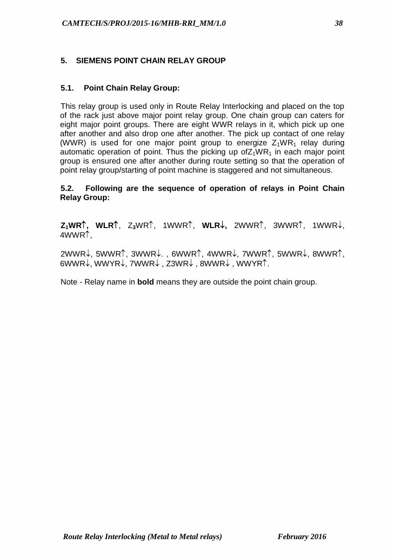
5. SIEMENS POINT CHAIN RELAY GROUP 5.1. Point Chain Relay Group: This relay group is used only in Route Relay Interlocking and placed on the top of the rack just above major point relay group. One chain group can caters for eight major point groups. There are eight WWR relays in it, which pick up one after another and also drop one after another. The pick up contact of one relay (WWR) is used for one major point group to energize Z1WR1 relay during automatic operation of point. Thus the picking up ofZ1WR1 in each major point group is ensured one after another during route setting so that the operation of point relay group/starting of point machine is staggered and not simultaneous. 5.2. Following are the sequence of operation of relays in Point Chain Relay Group:
Z1WR, WLR, Z3WR, 1WWR, WLR, 2WWR, 3WWR, 1WWR,
4WWR,
2WWR, 5WWR, 3WWR. , 6WWR, 4WWR, 7WWR, 5WWR, 8WWR,
6WWR, WWYR, 7WWR , Z3WR , 8WWR , WWYR. Note - Relay name in bold means they are outside the point chain group.

CAMTECH/S/PROJ/2015-16/MHB-RRI_MM/1.0 39
Route Relay Interlocking (Metal to Metal relays) February 2016
6. CONTROL OF OTHER THAN SIEMENS POINT MACHINE WITH SIEMENS POINT SWITCHING RELAY GROUP 6.1. Controls of other than Siemens Point machine using Point Switching Relay Group: This relay group is used in conjunction with Siemens Point Relay group (major or minor) wherever the operating feed for point machine is required to be arranged locally. This may be necessitated when other than Siemens Electric Point Machine is not Compatible with Siemens Point relay group are used or for point machines which are far away from relay room and does not get enough voltage from relay room. The point switching group work like a slave of the main point relay group. With the route initiated, the main point group initiating relay Z1WR picks up and relay WLR and Z1WR1 picks up. Z1WR1 switches on point switching group by operating Z1WR of P.S.G. In P.S.G WKR1 drops and W(R) R, W(R) PR and WKR2 operates. Z1WR of PSG operating opens WKR1 relay circuit of MPG and W(R)R operates and switches on normal or reverse point initiating relay i.e., Z1NWR or Z1RWR. After energizing of these relays WKR2 and WJR picks up. Simultaneously in case of normal operation of points relays (N) WLR1, 2.3 operate successively. Correspondingly relay (R) WLR1 2.3 operates for reverse operation. When the third relay operates point initiating relay Z1NWR or Z1RWR drops and switches on point contractor relay WR. WR in main group operating completes the circuit for (N) WR or (R) WR and N/RWR relay operates for both operations. (N) WR or (R) WR and N/RWR picking up WR relay operate, completing the motor operation circuit and the point are operated to the required position. When the point operation is completed WKR3 of PSG operates WKR3 of PSG switched on WKR3 of MPG and relay WKR2, WJR, WR in main group and WR, N/RWR in PSG drops, disconnecting point operation supply. Relay W (N) R, W (N) PR in PSG and W (N) R of MPG operate. WKR2 of PSG drops. W (N) R of MPG operating causes Z1WR of PSG to drop. WKR3 of both the groups drop WKR1 of PSG now operates and closed the circuit for WKR1 of MPG. Now W(R) LR operates locking the points electrically. For individual point operation the sequence of operation are same except for locking of point group electrically. 6.2. The sequence of operation is given below: a) WKR1 in main point group pick up as given below:
B60V WR WKR2, 270 Resistance, W(R)R, WJR, (N)WLR, (R)WR,
W(N)R, WKR, W(R)R, WKR2, WKR1 coil, (N)WLR1, (R) WLR3,

CAMTECH/S/PROJ/2015-16/MHB-RRI_MM/1.0 40
Route Relay Interlocking (Metal to Metal relays) February 2016
NWR,
WNR, Z1WR, WKR2, NWR, WNR, NWR, W(N)PR, WKR3, N-60. WKR1 in main point relay group picks up. b) Normal Detection Circuit: WKR1 relay in point switching group pick up as given below:
B60V, 270 resistance, WKR2 coil, W(N)PR, Z1WR, W(R)R, 97CT, ND
of A, 99 CT, (R)WR, WKR2, WKR1 coil, W(N)PR, 100 CT, ND of A, ND
of B, 98 CT, (N)WLR, W(R)R, WKR3, (N)WR1, W(R)PR, N60. c) Normal to Reverse Operation: The relays in the point switching group operates as given below:
Z1WR, WKR1, W(R)R, W(R)PR, WKR2, (R)WR, (NR)WR, WR,
WPR. The point is set to reverse.
WKR(1) , (B60V, W(R)R, (R)WLR, 99CT, RD of A, RD of B, 100 CT,
W(N)PR4., WKR3(I) coil, (NR)WR, N60, W(N)R, WKR3(II) , Z1WR, WR,
W(N)PR, (NR)WR, WKR3.
6.3. Sequence of Relay Operation : Main Point Relay Group Point Switching Relay Group Sequence of Relay operation is same as in case of main point Group Sequence of Relay Operation Main point Group and Point Switching group

CAMTECH/S/PROJ/2015-16/MHB-RRI_MM/1.0 41
Route Relay Interlocking (Metal to Metal relays) February 2016
Fig No: 6.1
7. CONTROL OF SIEMENS POINT MACHINE WITHOUT USING POINT GROUP

CAMTECH/S/PROJ/2015-16/MHB-RRI_MM/1.0 42
Route Relay Interlocking (Metal to Metal relays) February 2016
7.1. Control of point machine in Siemens RRI with out using major point group. For control of Sunderam Clayton LM 55 or Siemens point machines with out using a point group in relay room an additional relay group called as Siemens contractor relay group located at site is used to work in conjunction with the neutral and interlocked mini groups in the cabin. When the route is initiated, the concerned point initiating relay Z1WR picks up and switches on WLR, these two relay front contacts switches on point chain group WWR relays and finally WR1 operates and during individual point operation when the concern point button and group button is pressed WR1 operates directly proving track locking condition etc. WR1 switches on (R/N) WR1 relays this relay disconnects a supply to RKR or NKR and RR or NR relays, after dropping of these relays WR2 relay operates and this relay switches on (R/N) WR2 and NR/RR picks up. Now the circuit is ready to switch on point contactor relay unit at location. For this buttons are required to be released for individual point operation and in case point operation in route Z1WR relay drops and finally WR1 relay drops and now RWR or NWR relay operates at location, this relay switches on point contactor relay group. By operating N/R relay, W(R/N) R relays, XR and finally WCR relay. WCR relay is a contactor relay, having heavy-duty front contacts, with these. Contacts point operation supply is extended to point machine, once the point is set detected and locked in normal or reverse WNKR or WRKR picks up and drops RWR/NWR which causes NR, XR WCR to drop and feed to the point m/c is disconnected and now detection supply is extended from location to relay room to operate NKR or RKR once the NKR or RKR picks up and drops WR2 relay. Through NKR or RKR front contact steady indication is given on panels. If the point is operated in a route W(R)LR relay latches and locks the point circuit electrically and proving crank handle contact in the crank handle unit concern RWKR or NWKR relay picks up. 7.2 Following relays are used in relay room. All the relays are provided in mini groups only. 1) WNR :- Point button relay 2) WWNR :- Point group button relay 3) EWNR :- Emergency point group button relay. 4) Z1WR :- Point initiating relay to respond during route initiation 5) WLR :- Points lock relay 6) WWR :- Point switching staggering relay 7) WR1 :-Point initiating relay No.1 8) (R/N)WR1 :- (R)WR1 :- Reverse point control relay No1. (N)WR1: - Normal point control relay No1 9) RR :- Point group normal proving relay 10) NR :-Point group reverse proving relay. 11) WR2 :-Point operation initiating relay No.2 12) (R/N)WR2 :-(R)WR2:- reverse Point control relay No.2 (N)WR2:- Normal point control relay No. 2 13) NKR :- Point Normal detection relay 14) RKR :- Point Reverse detection relay 15)W(R/N)LR :- Point group electrically locking relay 16)RWKR :- Reverse point indication relay

CAMTECH/S/PROJ/2015-16/MHB-RRI_MM/1.0 43
Route Relay Interlocking (Metal to Metal relays) February 2016
17)NWKR :- Normal point indication relay 18) Z2 WR1 :- Panel Point indication controlling relays No1. 19) Z2WR2 :- Panel Point indication controlling relay No 2. 7.3. Relays provided in Siemens contactor unit: (at site or location) The Siemens contactor relay unit operates on 24 VDC. 1) N/R relay :- NORMAL/REVERSE OPERATION CONTROL RELAY It is provided with two coils. Once this relay energizes holds for 10 seconds through condenser discharge circuit. This relay does a function of time element relay. 2) W(R/N)R :- Point operation controlling relay:- It is an interlocked relay. a) When W(R)R picks up it closes reverse point operation circuits. b) When W(N)R picks up it closes normal point operation circuits. 3) XR :- One operation only ensuring relay:- It prevents recycles operation of point, when it is failed to set and locked. This relay is provided with a stick circuit and drops only when the RWR/NWR relay drops. 4) WCR:- Point contactor relay:- The power supply to the point machine is connected through the front contacts of WCR relay. It is provided with heavy-duty front contacts. Two number of `Q’ series neutral relays used for switching the point contactor relays are called as RWR and NWR. RWR:- Switches on the point contactor relay group to reverse position. NWR:- Switches on the point contactor relay group to normal position. Two number of `Q’ series relays are used in the location to detect the point normal and reverse position. a) WNKR:- Point Normal Indication relay:- This relay picks up proving that the point is set locked and detected in normal position and switches on NKR relay in Relay Room. b) WRKR:- Point Reverse Indication relay:- This relay picks up proving that the point is set locked and detected in Reverse position and switches on RKR relay in Relay Room. 7.4. Sequence of relay operation Automatic operation of point In Route / OV/ Isolation INDIVIDUALOPERATION

CAMTECH/S/PROJ/2015-16/MHB-RRI_MM/1.0 44
Route Relay Interlocking (Metal to Metal relays) February 2016
7.1

CAMTECH/S/PROJ/2015-16/MHB-RRI_MM/1.0 45
Route Relay Interlocking (Metal to Metal relays) February 2016
Relays Circuit in Relay Room for Point Operation
Fig No : 7.2

CAMTECH/S/PROJ/2015-16/MHB-RRI_MM/1.0 46
Route Relay Interlocking (Metal to Metal relays) February 2016
Point Operation Circuit without using point Group
Fig No : 7.3

CAMTECH/S/PROJ/2015-16/MHB-RRI_MM/1.0 47
Route Relay Interlocking (Metal to Metal relays) February 2016
Siemens Contactor Relay Group
Fig No :7.4

CAMTECH/S/PROJ/2015-16/MHB-RRI_MM/1.0 48
Route Relay Interlocking (Metal to Metal relays) February 2016
Point Detection Circuit
Fig No : 7.5

CAMTECH/S/PROJ/2015-16/MHB-RRI_MM/1.0 49
Route Relay Interlocking (Metal to Metal relays) February 2016
8. SEMI AUTOMATIC SIGNALS IN RRI (SIEMENS) 8.1. The semiautomatic signal for main line is first cleared by manual operation and converted into an automatic signal to enable successive trains to be passed with out the need for setting the routes. For making the signal to work as automatic, after clearing the signal, the concern signal button and AGGN, Automatic working initiating group button red in colour located on top of the control panel have to be pressed simultaneously. The details of introduction of auto working and its cancellation are dealt with in the following paragraphs. When the signal and route buttons for main line are pressed simultaneously and released, the route will be set and locked and the signal will be cleared. By pressing GN and AGGN button, relay GLSPR picks up and automatic route setting relay AU(R)R operates and latches. AU(R)R operating `A’ marker light lit on the signal. When the train passes the signal and occupies 1st track circuit, signal goes to danger and relay UDKR drops, proving the sequential actuation of track circuits. Concern UYR1 and UYR2 picks up and sticks. When the train clears route section track circuit relay UDKR picks up. With UYR1 and UYR2 relays pick up and proving the indication locking conditions of signal, the set sub route releases U(N)S relay operates. Once the route normalized GLSPR relay drop. When the train clears all the track circuit Automatic lock relay AULR picks up and sticks. This relay drops every time when the train passes the signal and picks up when it clears the route until automatic working is cancelled. With automatic lock relay AULR and signal unlocking relay G(N)LR operating, AUZ1UR automatic route initiating relay picks up. For each semiautomatic signal a separate route initiating relay is provided. These automatic route initiation relays are interlocked in similar way as the button relays to ensure only one route initiation at a time is possible. This relay operates only after a train has completed its movement over the route has been released. This is achieved by proving in its control circuit that a) Auto working is introduced AU(R)R front contact b) The previous train has passed completely over the route AULR front contact c) Signal is unlocked. G(N)LR front contact d) Signal, point and route button is not in pressed condition GNCR, UNCR & WNCR front contacts. AUZ1UR operating completes the route initiation circuit. The front contacts of GNPR and UNPR are by passed by AUZ1UR front contact. Proving other interlocking conditions Mn GZR and ZDUCR relay picks up, after this route setting operation takes place. Once the route is initiated and set, relay GLSR picks up and switches on GLSPR to operate. GLSPR picks up AUZ1UR relay drops and allthe route initiating relay drops and route locking and signal clearance takes place.

CAMTECH/S/PROJ/2015-16/MHB-RRI_MM/1.0 50
Route Relay Interlocking (Metal to Metal relays) February 2016
8.2. Automatic Working of Signals Sequence of Relay Operation First set the route for main line by pressing concern GN and UN. For converting manual working signal to auto working signal, press concern GN & AGGN buttons simultaneously.
In Route Initiation and Signal Clearance circuit, the front contact of GNPR and UNPR are by passed by AUZ1UR front contact. The sequence of relay operation for signal clearance is same as in the case of manual operation.

CAMTECH/S/PROJ/2015-16/MHB-RRI_MM/1.0 51
Route Relay Interlocking (Metal to Metal relays) February 2016
8.3. Cancellation of Automatic working At any time when it becomes necessary to cancel automatic working to enable diversion route to be set for a train or to put back the signal to on position in case of emergency. The auto working cancellation button to be operated. The cancellation of auto working comes under any one of the following conditions. a) Automatic working is initiated and the signal is displaying OFF aspect. b) Automatic working is initiated and the signal is displaying ON aspect. a) When the signal displaying OFF Aspect: First press signal button and AGGYN button simultaneously. Automatic working cancellation relay AUYR picks up and sticks and cuts off the supply to `A’ marker lamp and AECR relay drops. Proving signal displaying OFF aspect and `A’ marker light extinguished. Relay AU(N)R (Auto working relay normal coil) operates and latches and once AU(N)R picks up disconnect the supply to AUYR and AUYR relay drops. Now the signal is working as a manual signal. b) When the signal displaying ON aspect; First press signal button and AGGYN button simultaneously. Auto working Cancellation relay picks up and sticks, it causes the supply to `A’ marker lamp to be disconnected and AECR relay drops. Press signal button and full route cancellation button (EUUYN) simultaneously and release EUUYN button only and then press concern route button. Route cancellation relay EUYR picks up and releases set route sections, overlaps and auto working of signal. For circuit explanation refer circuit diagram no : 3.15 8.4. Automatic Working Cancellation Sequence of Relay Operation : I. When the Signal is at “OFF” Position :

CAMTECH/S/PROJ/2015-16/MHB-RRI_MM/1.0 52
Route Relay Interlocking (Metal to Metal relays) February 2016
II. When the Signal is at “ON” Position : a)

CAMTECH/S/PROJ/2015-16/MHB-RRI_MM/1.0 53
Route Relay Interlocking (Metal to Metal relays) February 2016
Fig No : 8.1

CAMTECH/S/PROJ/2015-16/MHB-RRI_MM/1.0 54
Route Relay Interlocking (Metal to Metal relays) February 2016
Fig No :8.2

CAMTECH/S/PROJ/2015-16/MHB-RRI_MM/1.0 55
Route Relay Interlocking (Metal to Metal relays) February 2016
9. POWER SUPPLY ARRANGEMENT WITH L.T PANEL 9.1. In route relay interlocking power supply plays a very important role and a non- interrupted power supply arrangement should be made available. Therefore, in practice various power supply sources are made available to the route relay cabin depending upon the local conditions. In electrified section, traction supply is made available for RRI cabins and local commercial power supply is also made available. In addition to this, in case of emergencies a standby diesel generator is automatically or manually started is made available and thus a continuous uninterrupted power supply is ensured. Stand by batteries are also provided to keep the circuit elements in their last operated position during the time of change over from main supply to the stand by supply. Generally, the supply made available is of 3 phase 440V, 50Hz and various transformers, rectifiers/battery chargers are employed to obtain different voltages required for different circuits. In signal lamp supply a constant voltage is required to be maintained. For this a constant voltage transformer i.e. voltage stabilizers are employed to over come the problem of supply fluctuations. In Siemens RRI, the supply arrangements also take into account the various load. Number of transformers, rectifiers/Battery chargers are employed, and generally the supply arrangement is made as under: a) D.C 120 Volts supply for operation of point machines b) D.C 60 volts supply for Internal circuits. c) D.C 60 volts supply for External circuits d) D.C 12 0r 24 volts supply for cutting in relay circuits e) A.C 110 volts supply for track circuits. f) A.C 110 volts supply for signal lamp circuits. g) A.C 24 volts supply for panel indication circuits. 9.2. Power Panel (Low tension panel) The power supply control panel is located separately in power supply room which consists of various controlling switches, supply indications in front of the panel, ammeters, voltmeters, frequency meters, voltage sensing relays, flasher relay, automatic power supply change over facility from main to standby supply whenever the main supply fails, various fuses, air circuit breakers with control equipment for various supplies etc. In addition of this, earth leakage detector sets for various circuits supply are also provided separately adjacent to the L.T. Panel. RRI Bhusaval, central Railway, power supply arrangement circuit is attached for reference. Ref Fig No : 9.1 to 9.8.

CAMTECH/S/PROJ/2015-16/MHB-RRI_MM/1.0 56
Route Relay Interlocking (Metal to Metal relays) February 2016
Fig No : 9.1

CAMTECH/S/PROJ/2015-16/MHB-RRI_MM/1.0 57
Route Relay Interlocking (Metal to Metal relays) February 2016
Fig No : 9.2

CAMTECH/S/PROJ/2015-16/MHB-RRI_MM/1.0 58
Route Relay Interlocking (Metal to Metal relays) February 2016
Fig No : 9.3

CAMTECH/S/PROJ/2015-16/MHB-RRI_MM/1.0 59
Route Relay Interlocking (Metal to Metal relays) February 2016
Fig No : 9.4

CAMTECH/S/PROJ/2015-16/MHB-RRI_MM/1.0 60
Route Relay Interlocking (Metal to Metal relays) February 2016
Fig No : 9.5

CAMTECH/S/PROJ/2015-16/MHB-RRI_MM/1.0 61
Route Relay Interlocking (Metal to Metal relays) February 2016
Fig No : 9.6
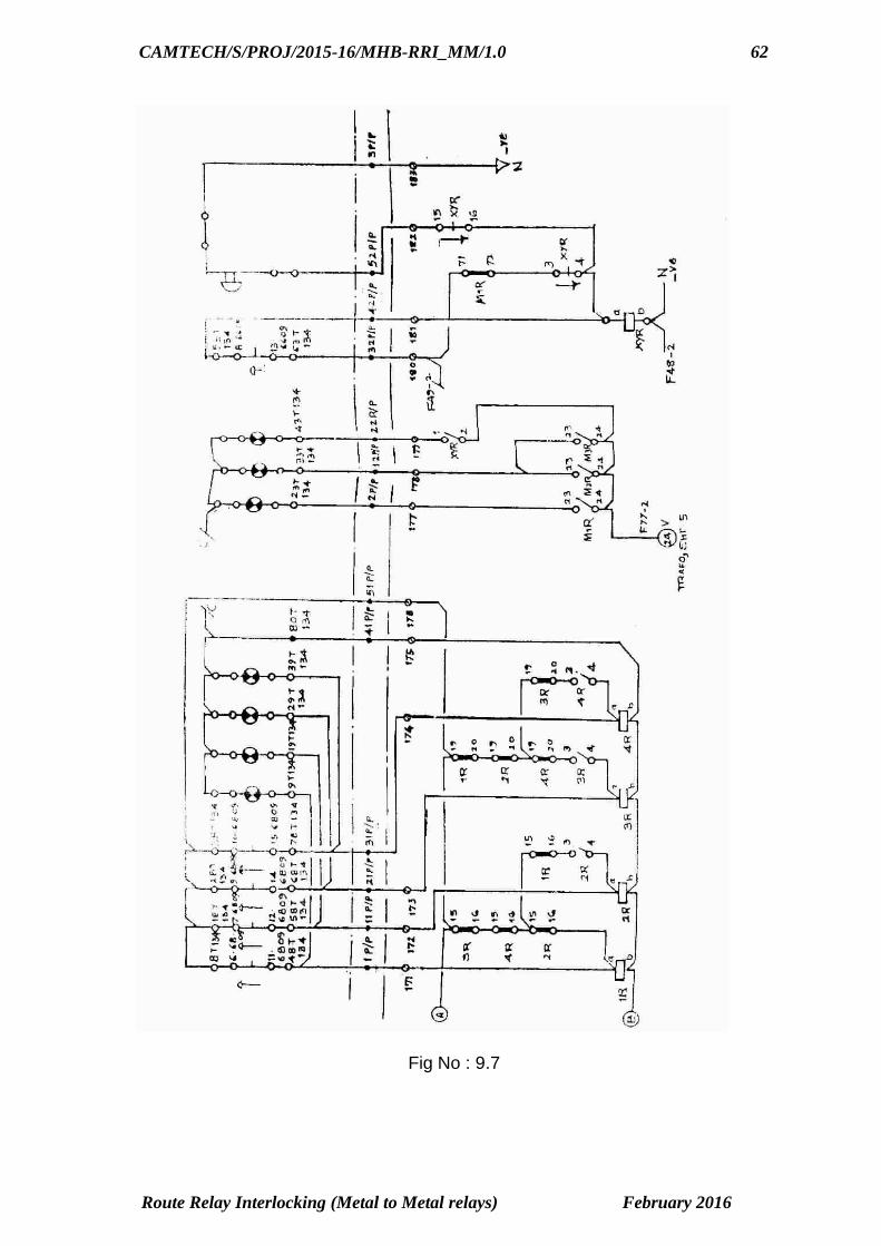
CAMTECH/S/PROJ/2015-16/MHB-RRI_MM/1.0 62
Route Relay Interlocking (Metal to Metal relays) February 2016
Fig No : 9.7

CAMTECH/S/PROJ/2015-16/MHB-RRI_MM/1.0 63
Route Relay Interlocking (Metal to Metal relays) February 2016
Fig No : 9.8
CAMTECH/S/PROJ/2015-16/MHB-RRI_MM/1.0 64
Route Relay Interlocking (Metal to Metal relays) February 2016
10. DO'S AND DON’T’S DO'S PANEL 1. Ensure that EWN and EUYN buttons are sealed properly. They are resealed properly after their use and entries are to be made in the register provided for the same. 2. Ensure that all counters are operating correctly and entries are recorded in the register along with reasons. 3. Ensure the cancellation of the sub routes by SI’s key and EUYN button and is done only after the receipt of the memo from operating staff and complete verification of the position of the routes. 4. Ensure that the crank handle box is sealed properly and entries of crank handle are recorded properly in the register. 5. Ensure that all the indications (route, point track, signals etc) are properly illuminated on the panel. 6. Ensure that visual/audible indications for signals, points and function failure indications etc. are indicated /displayed correctly. RELAY ROOM 7. Ensure that relay room is double locked, one by S&T staff and other by operating staff. Record entries in the special register for the purpose whenever the relay room is opened for maintenance or attending failures. 8. Ensure that signal, point, route group, mini group and other relays are sealed. 9. Ensure that testing of circuits, replacement of relays group etc are carried out only after the acceptance of disconnection memo by operating staff. 10. Record the track relay voltages regularly. 11. Carry out the locking testing of panel for various routes periodically and record in the register. 12. Carry our track locking, approach locking, route locking etc. periodically and record in the register. POWER ROOM 13. Record the various supply voltages AC & DC regularly. 14. Changeover periodically the stand by rectifiers transformer etc. through programmed switches. 15. Test periodically the automatic changeover arrangement of feeder, DG set and other supply for its proper functioning. DON’T’S 1. Do not open the relay room with out prior permission of operating staff and necessary entries in the register.

CAMTECH/S/PROJ/2015-16/MHB-RRI_MM/1.0 65
Route Relay Interlocking (Metal to Metal relays) February 2016
2. Do not allow unauthorized person to cancel the sub routes by SI’s key and EUYN button. 3. Do not interfere any signaling gears without issue of disconnection memo. 4. Do not test the auto change–over of supply arrangement and operate programmer switches when the train is in section. 5. Do not break and open seal of various relay groups and interfere with their contacts or lift their armatures. 6. Do not interfere with the wiring between tag blocks cable termination etc. 7. Do not leave the dry solder wires and loose wires unattended. 8. Do not cancel the sub route with SI’s key and EUYN button when there is train in the section with out proper verification. 9. Do not operate the EUYN button with SI,s key for cancellation of sub route until authority from SM Is obtained. 11. TROUBLE SHOOTING OF RRI & PI Some of the possible failure symptoms and the possible causes are given below.
S.No. FAILURE CAUSE
1. Control Panel blank a) Signal supply not available b) 24 V indication supply not available
2. Some of the routes are not setting or canceling and Latch relays are chattering
One of the input fuses of 140/40V DC transformer rectifiers is blown off and DC out put is reduced.
3. No route is setting a) One of the AUZUR’ s sticks in the picked up position c) NNCR is down
4. No overlap is setting COGGN stuck up in the operated position
5. After the passage of train first route is not getting cancelled
RE(Mn)CR Is down.
6. After the passage of light vehicle a route section is not canceling.
Sequential dropping and picking up of track relays missed during the passage of the vehicle.
7. After the passage of a train route is not canceling
Contact failure or may be fuse loose.
8. Routes are setting to one direction only
Direction relay is stuck up in one position
9. Route is getting cancelled by cancellation but not automatically
ZR down
10. Main signal route is not initiating
a) GNPR and MnGNPR is not picking up. b) Z1UR’s are not picking up. c) MnGZR is not picking up and holding. d) ZDUCR is not picking up

CAMTECH/S/PROJ/2015-16/MHB-RRI_MM/1.0 66
Route Relay Interlocking (Metal to Metal relays) February 2016
11. A shunt route is not initiating
a) SH GNPR and UNR is not picking up. b) Z1UR’s are not picking up c) SH GZR is not picking and holding d) ZDUCR is not picking up
12. Full route is not getting cancelled
a) Sh GNPR & Mn GNPR ,GNR or UNR is not picking up. b) EUUYNCR is not picking up c) AJTR or AJTR3 is not picking up when ATR is down
******************

CAMTECH/S/PROJ/2015-16/MHB-RRI_MM/1.0 67
Route Relay Interlocking (Metal to Metal relays) February 2016
REVIEW QUESTIONS Subjective : Q1. Prepare Flow Chart for Main Signal Clearance Circuit in case of Rout Setting type Siemens Relay Interlocking System? Q2. Prepare Flow Chart for Point Operation in case of. Rout Setting type Siemens Relay Interlocking System? Q3. Explain the Function of Point Chain Group? Q4. Explain the Function of following Relay I) Z 3 WR II) WWYR, III) Z1 UR1, iv) OVZ2U( R ) R V) W(R/N )LR vi) WLR Objective: STATE TRUE or FALSE 1. When ZU (R) R picks up Direction of movement will be from Left to Right. (False) 2. Feed to the GLSR Relay Cuts off when GPR Relay Pick up. (True) 3. GR1 Picks up proves that Signal in advance is not Blank. (True) 4. Sh-G(R) R is Shunt signal selecting relay (True) 5. UYR1 & UYR2 is route setting relay. (False) 6. ZR Relay pick contact up is must for Sequential Route Release circuit. of UYR 1 & UYR2 (True)

CAMTECH/S/PROJ/2015-16/MHB-RRI_MM/1.0 68
Route Relay Interlocking (Metal to Metal relays) February 2016
7. WKR1 is the final relay to pick up in point group. (False) 8. GNCR and UNCR Relays are normally energized relay. (True) 9. When A U(R) S is set, Reverse indication of point is proved. (False) 10. WKR2 is also picked up when point at site and Point group in relay room is not in correspondence. (False)