Maintenance and Modifications to Structural Systems
176
NIST NCSTAR 1-1C Federal Building and Fire Safety Investigation of the World Trade Center Disaster Maintenance and Modifications to Structural Systems David A. Fanella Arnaldo T. Derecho S. K. Ghosh
Transcript of Maintenance and Modifications to Structural Systems

NIST NCSTAR 1-1C
Federal Building and Fire Safety Investigation of the World Trade Center Disaster
Maintenance and Modifications to Structural Systems
David A. Fanella Arnaldo T. Derecho S. K. Ghosh


NIST NCSTAR 1-1C
Federal Building and Fire Safety Investigation of the World Trade Center Disaster
Maintenance and Modifications to Structural Systems
David A. Fanella Arnaldo T. Derecho S. K. Ghosh S. K. Ghosh Associates, Inc. September 2005
U.S. Department of Commerce Carlos M. Gutierrez, Secretary Technology Administration Michelle O’Neill, Acting Under Secretary for Technology National Institute of Standards and Technology William Jeffrey, Director

Disclaimer No. 1
Certain commercial entities, equipment, products, or materials are identified in this document in order to describe a procedure or concept adequately or to trace the history of the procedures and practices used. Such identification is not intended to imply recommendation, endorsement, or implication that the entities, products, materials, or equipment are necessarily the best available for the purpose. Nor does such identification imply a finding of fault or negligence by the National Institute of Standards and Technology.
Disclaimer No. 2
The policy of NIST is to use the International System of Units (metric units) in all publications. In this document, however, units are presented in metric units or the inch-pound system, whichever is prevalent in the discipline.
Disclaimer No. 3
Pursuant to section 7 of the National Construction Safety Team Act, the NIST Director has determined that certain evidence received by NIST in the course of this Investigation is “voluntarily provided safety-related information” that is “not directly related to the building failure being investigated” and that “disclosure of that information would inhibit the voluntary provision of that type of information” (15 USC 7306c).
In addition, a substantial portion of the evidence collected by NIST in the course of the Investigation has been provided to NIST under nondisclosure agreements.
Disclaimer No. 4
NIST takes no position as to whether the design or construction of a WTC building was compliant with any code since, due to the destruction of the WTC buildings, NIST could not verify the actual (or as-built) construction, the properties and condition of the materials used, or changes to the original construction made over the life of the buildings. In addition, NIST could not verify the interpretations of codes used by applicable authorities in determining compliance when implementing building codes. Where an Investigation report states whether a system was designed or installed as required by a code provision, NIST has documentary or anecdotal evidence indicating whether the requirement was met, or NIST has independently conducted tests or analyses indicating whether the requirement was met.
Use in Legal Proceedings
No part of any report resulting from a NIST investigation into a structural failure or from an investigation under the National Construction Safety Team Act may be used in any suit or action for damages arising out of any matter mentioned in such report (15 USC 281a; as amended by P.L. 107-231).
National Institute of Standards and Technology National Construction Safety Team Act Report 1-1C Natl. Inst. Stand. Technol. Natl. Constr. Sfty. Tm. Act Rpt. 1-1C, 392 pages (September 2005) CODEN: NSPUE2
U.S. GOVERNMENT PRINTING OFFICE WASHINGTON: 2005 _________________________________________ For sale by the Superintendent of Documents, U.S. Government Printing Office Internet: bookstore.gpo.gov — Phone: (202) 512-1800 — Fax: (202) 512-2250 Mail: Stop SSOP, Washington, DC 20402-0001

NIST NCSTAR 1-1C, WTC Investigation iii
ABSTRACT
This report documents maintenance and modifications that were made to the structural systems of World Trade Center (WTC) 1, 2, and 7. Included are the Port Authority of New York and New Jersey (PANYNJ or Port Authority) guidelines for inspection, repair, and modifications to the structural systems of WTC 1, 2, and 7. Discussed are the guidelines that governed the inspection and strengthening of existing structural members.
Also contained in this report is a summary of the structural inspection programs that were undertaken during the occupancy of WTC 1, 2, and 7. Included are summaries of the facility condition survey reports that were produced for WTC 1, 2, and 7 and descriptions of the structural integrity inspection programs that were undertaken for WTC 1 and WTC 2.
The significant modifications and repairs that were made to the structural systems of WTC 1, 2, and 7 from initial occupancy to September 11, 2001, are also documented. A discussion on the repairs that were made after the February 1993 bombing of WTC 1 is also included.
Appendixes to this report include copies of referenced documents, including the Tenant Construction Review Manuals; the Standards for Structural Integrity Inspection of the WTC towers; and the Architectural and Structural Design Guidelines, Specifications, and Standard Details, which were all issued by the Port Authority regarding inspection, repair, and modifications to the structural systems of WTC 1, 2, and 7.
Keywords: Bombing, construction, facility condition survey report, guidelines, inspection, modifications, repair, strengthening, structural integrity inspection program, structural systems, World Trade Center.

Abstract
iv NIST NCSTAR 1-1C, WTC Investigation
This page intentionally left blank.
NIST NCSTAR 1-1C, WTC Investigation v
TABLE OF CONTENTS
Abstract ........................................................................................................................................................ iii Table of Contents.......................................................................................................................................... v List of Figures .............................................................................................................................................. ix List of Tables ............................................................................................................................................... xi List of Acronyms and Abbreviations .........................................................................................................xiii Metric Conversion Table ............................................................................................................................ xv Preface ....................................................................................................................................................... xix Executive Summary ................................................................................................................................. xxix
Chapter 1 Introduction ..................................................................................................................1
Chapter 2 Guidelines for Inspection, Repair, and Modifications to Structural Systems ........ 3 2.1 Tenant Construction Review Manuals............................................................................................. 3
2.1.1 1971 Edition ......................................................................................................................... 4 2.1.2 1979 Edition ......................................................................................................................... 9 2.1.3 March 1984 Edition, Revised March 1990......................................................................... 14 2.1.4 March 1997 Edition............................................................................................................ 17
2.2 Standards for Structural Integrity Inspection of the World Trade Center Towers A & B ............. 18 2.2.1 Overview ............................................................................................................................ 18 2.2.2 Inspection Program............................................................................................................. 20 2.2.3 In-House Inspection Personnel........................................................................................... 24 2.2.4 Outside Consultants and Suppliers of Special Services ..................................................... 25 2.2.5 Record Keeping and Follow-up Procedure ........................................................................ 26 2.2.6 Excluded Work................................................................................................................... 28
2.3 Architectural and Structural Design Guidelines, Specifications and Standard Details.................. 28 2.3.1 Structural Design Guidelines.............................................................................................. 28 2.3.2 Structural Specifications..................................................................................................... 30
2.4 References...................................................................................................................................... 31
Chapter 3 Structural Inspection Programs During the Occupancy of WTC 1, 2, and 7 ........ 33 3.1 Facility Condition Survey Reports................................................................................................. 33
3.1.1 Port Authority Facility Condition Survey Program – WTC 2............................................ 33

Table of Contents
vi NIST NCSTAR 1-1C, WTC Investigation
3.1.2 Port Authority Facility Condition Survey Program – WTC 1............................................ 43 3.1.3 Port Authority Facility Condition Survey Program – WTC 7............................................ 53 3.1.4 Due Diligence Physical Condition Survey – WTC 1 and WTC 2...................................... 58
3.2 Structural Integrity Inspection Program......................................................................................... 59 3.2.1 Overview ............................................................................................................................ 59 3.2.2 Summary of Structural Integrity Inspection Program Reports ........................................... 61
3.3 Summary of Structural Inspection Programs ................................................................................. 80 3.3.1 Inspection Programs ........................................................................................................... 80 3.3.2 Findings from Inspection Programs ................................................................................... 81
3.4 References...................................................................................................................................... 93
Chapter 4 Significant Modifications and Repairs to the Structural Framing Systems of WTC 1, 2, and 7 ......................................................................................................................... 95
4.1 Overview........................................................................................................................................ 95 4.2 Modifications and Repairs Made to WTC 1 .................................................................................. 95
4.2.1 Openings Made in Floor Slabs ........................................................................................... 95 4.2.2 Openings in Floor Slabs That Were Subsequently Closed................................................. 95 4.2.3 Structural Members That Were Reinforced........................................................................ 97 4.2.4 Repair Work Following the February 26, 1993 Explosion ................................................ 97 4.2.5 Other Modifications ......................................................................................................... 114
4.3 Modifications and Repairs Made to WTC 2 ................................................................................ 114 4.3.1 Openings Made in Floor Slabs ......................................................................................... 114 4.3.2 Openings in Floor Slabs That Were Subsequently Closed............................................... 115 4.3.3 Structural Members That Were Reinforced...................................................................... 116 4.3.4 Other Modifications ......................................................................................................... 116
4.4 Modifications and Repairs Made to WTC 7 ................................................................................ 116 4.4.1 Modifications Made due to New Loading Requirements................................................. 116 4.4.2 Openings Made in Floor Slabs ......................................................................................... 119 4.4.3 Modifications Made to Beam Webs and Flanges............................................................. 119 4.4.4 Other Modifications ......................................................................................................... 120
4.5 References.................................................................................................................................... 121

Table of Contents
NIST NCSTAR 1-1C, WTC Investigation vii
Appendix A Tenant Construction Review Manual – 1971 ........................................................................ 123
Appendix B Tenant Construction Review Manual – 1979 ........................................................................ 139
Appendix C Tenant Construction Review Manual – 1990 ........................................................................ 157
Appendix D Tenant Construction Review Manual – 1997 ........................................................................ 177
Appendix E Standards for Structural Integrity Inspection of WTC Towers A & B................................. 199
Appendix F Architectural and Structural Design Guidelines, Specifications, and Standard Details...................................................................................................................... 255
Appendix G Supporting Documents .......................................................................................................... 299

Table of Contents
viii NIST NCSTAR 1-1C, WTC Investigation
This page intentionally left blank.

NIST NCSTAR 1-1C, WTC Investigation ix
LIST OF FIGURES
Figure P–1. The eight projects in the federal building and fire safety investigation of the WTC disaster. ................................................................................................................................. xxi
Figure 3–1. Typical inspection locations of exterior wall per 1990 Condition Survey Report of WTC 2.................................................................................................................................... 36
Figure 3–2. Splice details at typical inspection locations of exterior wall per the 1990 Condition Survey Report of WTC 2. ...................................................................................................... 38
Figure 3–3. Typical inspection locations of floor framing per the 1990 Condition Survey Report of WTC 2.................................................................................................................................... 41
Figure 3–4. Recommendations made in the 1997 Facility Condition Survey Report for WTC 7. ............ 57 Figure 3–5. Estimated manpower and cost estimates for structural integrity inspections for WTC 1
and WTC 2. ............................................................................................................................ 63
Figure 4–1. Damage assessment for WTC 1 at Level B1. ......................................................................... 99 Figure 4–2. Damage assessment for WTC 1 at Level B2. ....................................................................... 100 Figure 4−3. Bracing on south face of WTC 1 damaged by blast. ............................................................ 101 Figure 4−4. Repair of damaged bracing in levels B1 and B2 of WTC 1. ................................................ 103 Figure 4−5. Repair of damaged spandrel beam in level B1 of WTC 1.................................................... 104 Figure 4−6. Repair of cracked weld on spandrel beam in level B1 of WTC 1. ....................................... 104 Figure 4−7. Repair of damaged floor beams at Level B1 in WTC 1. ...................................................... 105 Figure 4−8. Repair of damaged floor beam at Level B3 in WTC 1......................................................... 106 Figure 4−9. Repair of damaged floor beam at Level B3 in WTC 1......................................................... 107 Figure 4−10. Repair of damaged reinforced concrete spandrel beam at Level B3 in WTC 1. ................. 108 Figure 4−11. Repair of damaged reinforced concrete spandrel beam at Level B4 in WTC 1. ................. 109 Figure 4−12. Concrete masonry encasement of columns at subgrade levels in WTC 1.......................... 110 Figure 4−13. Reconstruction details for existing encased steel beams in WTC 1. .................................. 111 Figure 4−14. Repair of encased steel spandrel beam at Level B5 in WTC 1. ......................................... 112 Figure 4−15. Repair of beam connection at Concourse Level in WTC 1. ............................................... 113

List of Figures
x NIST NCSTAR 1-1C, WTC Investigation
This page intentionally left blank.

NIST NCSTAR 1-1C, WTC Investigation xi
LIST OF TABLES
Table P–1. Federal building and fire safety investigation of the WTC disaster....................................... xx Table P–2. Public meetings and briefings of the WTC Investigation. ..................................................xxiii
Table 2–1. Checklist for Structural Review in the 1971 Edition of the Tenant Construction Manual................................................................................................................ 5
Table 2–2. Inspection requirements in the 1971 edition of the Tenant Construction Manual. .................. 8 Table 2–3. Checklist for structural review in the 1979 edition of the Tenant Construction Manual. ...... 11 Table 2–4. Checklist for items subject to controlled inspection in the 1979 edition of the Tenant
Construction Manual.............................................................................................................. 13 Table 2–5. Details of structural review in the 1990 edition of the Tenant Construction Manual. ........... 16 Table 2–6. Checklist for items subject to controlled inspection in the 1990 edition of the Tenant
Construction Manual.............................................................................................................. 17 Table 2–7. Checklist for items subject to controlled inspection in the 1997 edition of the Tenant
Construction Manual.............................................................................................................. 19 Table 2–8. Defects and signs of distress to be recorded during inspection of WTC 1 and WTC 2......... 26 Table 2–9. Minimum loads specified for tenant alterations in PANYNJ Architectural and
Structural Design Guidelines, Specifications, and Standard Details...................................... 29
Table 3–1. Percentage of structural elements inspected per office floor and for the entire tower per the 1990 Facility Condition Survey Report for WTC 2. ........................................................ 35
Table 3–2. Number of structural elements inspected per office floor per the 1991 Facility Condition Survey Report for WTC 1. .................................................................................... 44
Table 3–3. Findings from inspection of exterior wall column splices in WTC 1. ................................... 46 Table 3–4. Visual inspection of elevator core framing in WTC 1. .......................................................... 47 Table 3–5. Locations of holes in gypsum wallboard around elevators in WTC 1. .................................. 48 Table 3–6. Core column connection inspection in WTC 1. ..................................................................... 49 Table 3–7. Floor framing and slab inspection results for WTC 1. ........................................................... 51 Table 3–8. Core framing inspection results for WTC 1. .......................................................................... 52 Table 3–9. Column splice inspection points in WTC 7. .......................................................................... 54 Table 3–10. Wind inspection points, columns, in WTC 7. ........................................................................ 55 Table 3–11. Wind inspection points, girders, in WTC 7............................................................................ 55 Table 3–12. Interior beam connection inspection points in WTC 7. ......................................................... 56 Table 3–13. Summary of findings from space usage reports. .................................................................... 65 Table 3–14. Summary of findings from accessible columns reports. ........................................................ 66

List of Tables
xii NIST NCSTAR 1-1C, WTC Investigation
Table 3–15. Summary of findings from Plaza Level box column report................................................... 68 Table 3–16. Summary of findings from bracing reports. ........................................................................... 69 Table 3–17. Summary of findings from hat truss reports. ......................................................................... 70 Table 3–18. Summary of findings from reports on floor framing over mechanical areas. ........................ 72 Table 3–19. Summary of findings from reports on floor framing over tenant areas.................................. 75 Table 3–20. Reports on natural frequency measurements. ........................................................................ 76 Table 3–21. Measured first mode natural frequencies for WTC 1............................................................. 76 Table 3–22. Summary of natural frequency test results for floors of WTC 1, March 1971. ..................... 77 Table 3–23. Summary of natural frequency test results for floors of WTC 1 and WTC 2,
March 1995. ........................................................................................................................... 77 Table 3–24. Summary of inspections performed on WTC 1 after the terrorist bombing on
February 16, 1993. ................................................................................................................. 79 Table 3–25. Summary of locations where fireproofing was found missing during structural
inspections of WTC 1, 2, and 7.............................................................................................. 82
Table 4−1. Openings made in floor slabs in WTC 1. ............................................................................... 96 Table 4−2. Openings in floor slabs that were closed in WTC 1............................................................... 97 Table 4−3. Structural members that were reinforced in WTC 1. ............................................................. 98 Table 4−4. Openings made in floor slabs in WTC 2. ............................................................................. 115 Table 4−5. Openings in floor slabs that were closed in WTC 2............................................................. 115 Table 4−6. Structural members that were reinforced in WTC 2. ........................................................... 116 Table 4–7. Modifications made due to new loading requirements in WTC 7. ...................................... 117 Table 4–8. Openings made in floor slabs of WTC 7.............................................................................. 120 Table 4–9. Modifications made to beam webs and flanges in WTC 7. ................................................. 121
NIST NCSTAR 1-1C, WTC Investigation xiii
LIST OF ACRONYMS AND ABBREVIATIONS
Acronyms
AISC American Institute of Steel Construction
ASTM American Society for Testing and Materials
BSA Board of Standards and Appeals, New York City
BOCA Building Officials & Code Administrators International, Inc.
BPS Building Performance Study
CMU concrete masonry unit
EQAD Engineering Quality Assurance Division
FEMA Federal Emergency Management Agency
HVAC heating, ventilation, and air conditioning
LERA Leslie E. Robertson Associates
MEA Materials and Equipment Acceptance Division of the Office of the Commissioner of the Buildings Department of New York City
MER mechanical equipment room
NIST National Institute of Standards and Technology
NYC New York City
PANYNJ Port Authority of New York and New Jersey
PONYA Port of New York Authority
SHCR Skilling, Helle, Christiansen, Robertson
SII Structural Integrity Inspection
WSHJ Worthington, Skilling, Helle, and Jackson
WTC World Trade Center
WTC 1 World Trade Center tower 1 (North Tower)
WTC 2 World Trade Center tower 2 (South Tower)
WTC 7 World Trade Center building 7
Abbreviations
ft feet
g acceleration due to gravity = 32.2 ft/s2

List of Acronyms and Abbreviations
xiv NIST NCSTAR 1-1C, WTC Investigation
Hz Hertz
in. inch
lb pounds
milli 1/1000
min minute
mph miles per hour
pcf pounds per cubic foot
psf pounds per square foot
s second
sq ft square foot

NIST NCSTAR 1-1C, WTC Investigation xv
METRIC CONVERSION TABLE
To convert from to Multiply by
AREA AND SECOND MOMENT OF AREA square foot (ft2) square meter (m2) 9.290 304 E-02
square inch (in.2) square meter (m2) 6.4516 E-04
square inch (in.2) square centimeter (cm2) 6.4516 E+00
square yard (yd2) square meter (m2) 8.361 274 E-01
ENERGY (includes WORK)
kilowatt hour (kW ⋅ h) joule (J) 3.6 E+06
quad (1015 BtuIT) joule (J) 1.055 056 E+18
therm (U.S.) joule (J) 1.054 804 E+08
ton of TNT (energy equivalent) joule (J) 4.184 E+09
watt hour (W ⋅ h) joule (J) 3.6 E+03
watt second (W ⋅ s) joule (J) 1.0 E+00
FORCE dyne (dyn) newton (N) 1.0 E-05
kilogram-force (kgf) newton (N) 9.806 65 E+00
kilopond (kilogram-force) (kp) newton (N) 9.806 65 E+00
kip (1 kip=1,000 lbf) newton (N) 4.448 222 E+03
kip (1 kip=1,000 lbf) kilonewton (kN) 4.448 222 E+00
pound-force (lbf) newton (N) 4.448 222 E+00
FORCE DIVIDED BY LENGTH pound-force per foot (lbf/ft) newton per meter (N/m) 1.459 390 E+01
pound-force per inch (lbf/in.) newton per meter (N/m) 1.751 268 E+02
HEAT FLOW RATE calorieth per minute (calth/min) watt (W) 6.973 333 E-02
calorieth per second (calth/s) watt (W) 4.184 E+00
kilocalorieth per minute (kcalth/min) watt (W) 6.973 333 E+01
kilocalorieth per second (kcalth/s) watt (W) 4.184 E+03

Metric Conversion Table
xvi NIST NCSTAR 1-1C, WTC Investigation
To convert from to Multiply by
LENGTH foot (ft) meter (m) 3.048 E-01
inch (in) meter (m) 2.54 E-02
inch (in.) centimeter (cm) 2.54 E+00
micron (m) meter (m) 1.0 E-06
yard (yd) meter (m) 9.144 E-01
MASS and MOMENT OF INERTIA kilogram-force second squared
per meter (kgf ⋅ s2/m) kilogram (kg) 9.806 65 E+00
pound foot squared (lb ⋅ ft2) kilogram meter squared (kg ⋅ m2) 4.214 011 E-02
pound inch squared (lb ⋅ in.2) kilogram meter squared (kg ⋅ m2) 2.926 397 E-04
ton, metric (t) kilogram (kg) 1.0 E+03
ton, short (2,000 lb) kilogram (kg) 9.071 847 E+02
MASS DIVIDED BY AREA pound per square foot (lb/ft2) kilogram per square meter (kg/m2) 4.882 428 E+00
pound per square inch (not pound force) (lb/in.2) kilogram per square meter (kg/m2) 7.030 696 E+02
MASS DIVIDED BY LENGTH pound per foot (lb/ft) kilogram per meter (kg/m) 1.488 164 E+00
pound per inch (lb/in.) kilogram per meter (kg/m) 1.785 797 E+01
pound per yard (lb/yd) kilogram per meter (kg/m) 4.960 546 E-01
PRESSURE or STRESS (FORCE DIVIDED BY AREA) kilogram-force per square centimeter (kgf/cm2) pascal (Pa) 9.806 65 E+04
kilogram-force per square meter (kgf/m2) pascal (Pa) 9.806 65 E+00
kilogram-force per square millimeter (kgf/mm2) pascal (Pa) 9.806 65 E+06
kip per square inch (ksi) (kip/in.2) pascal (Pa) 6.894 757 E+06
kip per square inch (ksi) (kip/in.2) kilopascal (kPa) 6.894 757 E+03
pound-force per square foot (lbf/ft2) pascal (Pa) 4.788 026 E+01
pound-force per square inch (psi) (lbf/in.2) pascal (Pa) 6.894 757 E+03
pound-force per square inch (psi) (lbf/in.2) kilopascal (kPa) 6.894 757 E+00
psi (pound-force per square inch) (lbf/in.2) pascal (Pa) 6.894 757 E+03
psi (pound-force per square inch) (lbf/in.2) kilopascal (kPa) 6.894 757 E+00

Metric Conversion Table
NIST NCSTAR 1-1C, WTC Investigation xvii
To convert from to Multiply by
TEMPERATURE
degree Celsius (°C) kelvin (K) T/K = t/°C + 273.15
degree centigrade degree Celsius (°C) t/°C ≈ t /deg. cent.
degree Fahrenheit (°F) degree Celsius (°C) t/°C = (t/°F - 32)/1.8
degree Fahrenheit (°F) kelvin (K) T/K = (t/°F + 459.67)/1.8
kelvin (K) degree Celsius (°C) t/°C = T/K 2 273.15
TEMPERATURE INTERVAL
degree Celsius (°C) kelvin (K) 1.0 E+00
degree centigrade degree Celsius (°C) 1.0 E+00
degree Fahrenheit (°F) degree Celsius (°C) 5.555 556 E-01
degree Fahrenheit (°F) kelvin (K) 5.555 556 E-01
degree Rankine (°R) kelvin (K) 5.555 556 E-01
VELOCITY (includes SPEED) foot per second (ft/s) meter per second (m/s) 3.048 E-01
inch per second (in./s) meter per second (m/s) 2.54 E-02
kilometer per hour (km/h) meter per second (m/s) 2.777 778 E-01
mile per hour (mi/h) kilometer per hour (km/h) 1.609 344 E+00
mile per minute (mi/min) meter per second (m/s) 2.682 24 E+01
VOLUME (includes CAPACITY) cubic foot (ft3) cubic meter (m3) 2.831 685 E-02
cubic inch (in.3 ) cubic meter (m3) 1.638 706 E-05
cubic yard (yd3) cubic meter (m3) 7.645 549 E-01
gallon (U.S.) (gal) cubic meter (m3) 3.785 412 E-03
gallon (U.S.) (gal) liter (L) 3.785 412 E+00
liter (L) cubic meter (m3) 1.0 E-03
ounce (U.S. fluid) (fl oz) cubic meter (m3) 2.957 353 E-05
ounce (U.S. fluid) (fl oz) milliliter (mL) 2.957 353 E+01

Metric Conversion Table
xviii NIST NCSTAR 1-1C, WTC Investigation
This page intentionally left blank.

NIST NCSTAR 1-1C, WTC Investigation xix
PREFACE
Genesis of This Investigation
Immediately following the terrorist attack on the World Trade Center (WTC) on September 11, 2001, the Federal Emergency Management Agency (FEMA) and the American Society of Civil Engineers began planning a building performance study of the disaster. The week of October 7, as soon as the rescue and search efforts ceased, the Building Performance Study Team went to the site and began its assessment. This was to be a brief effort, as the study team consisted of experts who largely volunteered their time away from their other professional commitments. The Building Performance Study Team issued its report in May 2002, fulfilling its goal “to determine probable failure mechanisms and to identify areas of future investigation that could lead to practical measures for improving the damage resistance of buildings against such unforeseen events.”
On August 21, 2002, with funding from the U.S. Congress through FEMA, the National Institute of Standards and Technology (NIST) announced its building and fire safety investigation of the WTC disaster. On October 1, 2002, the National Construction Safety Team Act (Public Law 107-231), was signed into law. The NIST WTC Investigation was conducted under the authority of the National Construction Safety Team Act.
The goals of the investigation of the WTC disaster were:
• To investigate the building construction, the materials used, and the technical conditions that contributed to the outcome of the WTC disaster.
• To serve as the basis for:
− Improvements in the way buildings are designed, constructed, maintained, and used;
− Improved tools and guidance for industry and safety officials;
− Recommended revisions to current codes, standards, and practices; and
− Improved public safety.
The specific objectives were:
1. Determine why and how WTC 1 and WTC 2 collapsed following the initial impacts of the aircraft and why and how WTC 7 collapsed;
2. Determine why the injuries and fatalities were so high or low depending on location, including all technical aspects of fire protection, occupant behavior, evacuation, and emergency response;
3. Determine what procedures and practices were used in the design, construction, operation, and maintenance of WTC 1, 2, and 7; and
4. Identify, as specifically as possible, areas in current building and fire codes, standards, and practices that warrant revision.

Preface
xx NIST NCSTAR 1-1C, WTC Investigation
NIST is a nonregulatory agency of the U.S. Department of Commerce’s Technology Administration. The purpose of NIST investigations is to improve the safety and structural integrity of buildings in the United States, and the focus is on fact finding. NIST investigative teams are authorized to assess building performance and emergency response and evacuation procedures in the wake of any building failure that has resulted in substantial loss of life or that posed significant potential of substantial loss of life. NIST does not have the statutory authority to make findings of fault nor negligence by individuals or organizations. Further, no part of any report resulting from a NIST investigation into a building failure or from an investigation under the National Construction Safety Team Act may be used in any suit or action for damages arising out of any matter mentioned in such report (15 USC 281a, as amended by Public Law 107-231).
Organization of the Investigation
The National Construction Safety Team for this Investigation, appointed by the then NIST Director, Dr. Arden L. Bement, Jr., was led by Dr. S. Shyam Sunder. Dr. William L. Grosshandler served as Associate Lead Investigator, Mr. Stephen A. Cauffman served as Program Manager for Administration, and Mr. Harold E. Nelson served on the team as a private sector expert. The Investigation included eight interdependent projects whose leaders comprised the remainder of the team. A detailed description of each of these eight projects is available at http://wtc.nist.gov. The purpose of each project is summarized in Table P–1, and the key interdependencies among the projects are illustrated in Fig. P–1.
Table P–1. Federal building and fire safety investigation of the WTC disaster. Technical Area and Project Leader Project Purpose
Analysis of Building and Fire Codes and Practices; Project Leaders: Dr. H. S. Lew and Mr. Richard W. Bukowski
Document and analyze the code provisions, procedures, and practices used in the design, construction, operation, and maintenance of the structural, passive fire protection, and emergency access and evacuation systems of WTC 1, 2, and 7.
Baseline Structural Performance and Aircraft Impact Damage Analysis; Project Leader: Dr. Fahim H. Sadek
Analyze the baseline performance of WTC 1 and WTC 2 under design, service, and abnormal loads, and aircraft impact damage on the structural, fire protection, and egress systems.
Mechanical and Metallurgical Analysis of Structural Steel; Project Leader: Dr. Frank W. Gayle
Determine and analyze the mechanical and metallurgical properties and quality of steel, weldments, and connections from steel recovered from WTC 1, 2, and 7.
Investigation of Active Fire Protection Systems; Project Leader: Dr. David D. Evans; Dr. William Grosshandler
Investigate the performance of the active fire protection systems in WTC 1, 2, and 7 and their role in fire control, emergency response, and fate of occupants and responders.
Reconstruction of Thermal and Tenability Environment; Project Leader: Dr. Richard G. Gann
Reconstruct the time-evolving temperature, thermal environment, and smoke movement in WTC 1, 2, and 7 for use in evaluating the structural performance of the buildings and behavior and fate of occupants and responders.
Structural Fire Response and Collapse Analysis; Project Leaders: Dr. John L. Gross and Dr. Therese P. McAllister
Analyze the response of the WTC towers to fires with and without aircraft damage, the response of WTC 7 in fires, the performance of composite steel-trussed floor systems, and determine the most probable structural collapse sequence for WTC 1, 2, and 7.
Occupant Behavior, Egress, and Emergency Communications; Project Leader: Mr. Jason D. Averill
Analyze the behavior and fate of occupants and responders, both those who survived and those who did not, and the performance of the evacuation system.
Emergency Response Technologies and Guidelines; Project Leader: Mr. J. Randall Lawson
Document the activities of the emergency responders from the time of the terrorist attacks on WTC 1 and WTC 2 until the collapse of WTC 7, including practices followed and technologies used.

Preface
NIST NCSTAR 1-1C, WTC Investigation xxi
NIST WTC Investigation ProjectsNIST WTC Investigation Projects
Analysis of Steel
Structural Collapse
Evacuation
Baseline Performance
& Impact Damage
Analysis of Codes and Practices
Emergency Response
Active Fire Protection
Thermal and Tenability
Environment
Video/Photographic Records
Oral History Data
Emergency Response Records
Recovered Structural Steel
WTC Building Performance StudyRecommendations
Government, Industry, Professional, Academic Inputs
Public Inputs
Figure P–1. The eight projects in the federal building and fire safety
investigation of the WTC disaster.
National Construction Safety Team Advisory Committee
The NIST Director also established an advisory committee as mandated under the National Construction Safety Team Act. The initial members of the committee were appointed following a public solicitation. These were:
• Paul Fitzgerald, Executive Vice President (retired) FM Global, National Construction Safety Team Advisory Committee Chair
• John Barsom, President, Barsom Consulting, Ltd.
• John Bryan, Professor Emeritus, University of Maryland
• David Collins, President, The Preview Group, Inc.
• Glenn Corbett, Professor, John Jay College of Criminal Justice
• Philip DiNenno, President, Hughes Associates, Inc.
Preface
xxii NIST NCSTAR 1-1C, WTC Investigation
• Robert Hanson, Professor Emeritus, University of Michigan
• Charles Thornton, Co-Chairman and Managing Principal, The Thornton-Tomasetti Group, Inc.
• Kathleen Tierney, Director, Natural Hazards Research and Applications Information Center, University of Colorado at Boulder
• Forman Williams, Director, Center for Energy Research, University of California at San Diego
This National Construction Safety Team Advisory Committee provided technical advice during the Investigation and commentary on drafts of the Investigation reports prior to their public release. NIST has benefited from the work of many people in the preparation of these reports, including the National Construction Safety Team Advisory Committee. The content of the reports and recommendations, however, are solely the responsibility of NIST.
Public Outreach
During the course of this Investigation, NIST held public briefings and meetings (listed in Table P–2) to solicit input from the public, present preliminary findings, and obtain comments on the direction and progress of the Investigation from the public and the Advisory Committee.
NIST maintained a publicly accessible Web site during this Investigation at http://wtc.nist.gov. The site contained extensive information on the background and progress of the Investigation.
NIST’s WTC Public-Private Response Plan
The collapse of the WTC buildings has led to broad reexamination of how tall buildings are designed, constructed, maintained, and used, especially with regard to major events such as fires, natural disasters, and terrorist attacks. Reflecting the enhanced interest in effecting necessary change, NIST, with support from Congress and the Administration, has put in place a program, the goal of which is to develop and implement the standards, technology, and practices needed for cost-effective improvements to the safety and security of buildings and building occupants, including evacuation, emergency response procedures, and threat mitigation.
The strategy to meet this goal is a three-part NIST-led public-private response program that includes:
• A federal building and fire safety investigation to study the most probable factors that contributed to post-aircraft impact collapse of the WTC towers and the 47-story WTC 7 building, and the associated evacuation and emergency response experience.
• A research and development (R&D) program to (a) facilitate the implementation of recommendations resulting from the WTC Investigation, and (b) provide the technical basis for cost-effective improvements to national building and fire codes, standards, and practices that enhance the safety of buildings, their occupants, and emergency responders.

Preface
NIST NCSTAR 1-1C, WTC Investigation xxiii
Table P–2. Public meetings and briefings of the WTC Investigation. Date Location Principal Agenda
June 24, 2002 New York City, NY Public meeting: Public comments on the Draft Plan for the pending WTC Investigation.
August 21, 2002 Gaithersburg, MD Media briefing announcing the formal start of the Investigation. December 9, 2002 Washington, DC Media briefing on release of the Public Update and NIST request
for photographs and videos. April 8, 2003
New York City, NY Joint public forum with Columbia University on first-person interviews.
April 29–30, 2003 Gaithersburg, MD NCST Advisory Committee meeting on plan for and progress on WTC Investigation with a public comment session.
May 7, 2003 New York City, NY Media briefing on release of May 2003 Progress Report. August 26–27, 2003 Gaithersburg, MD NCST Advisory Committee meeting on status of the WTC
investigation with a public comment session. September 17, 2003 New York City, NY Media and public briefing on initiation of first-person data
collection projects. December 2–3, 2003 Gaithersburg, MD NCST Advisory Committee meeting on status and initial results
and release of the Public Update with a public comment session. February 12, 2004 New York City, NY Public meeting on progress and preliminary findings with public
comments on issues to be considered in formulating final recommendations.
June 18, 2004 New York City, NY Media/public briefing on release of June 2004 Progress Report. June 22–23, 2004 Gaithersburg, MD NCST Advisory Committee meeting on the status of and
preliminary findings from the WTC Investigation with a public comment session.
August 24, 2004 Northbrook, IL Public viewing of standard fire resistance test of WTC floor system at Underwriters Laboratories, Inc.
October 19–20, 2004 Gaithersburg, MD NCST Advisory Committee meeting on status and near complete set of preliminary findings with a public comment session.
November 22, 2004 Gaithersburg, MD NCST Advisory Committee discussion on draft annual report to Congress, a public comment session, and a closed session to discuss pre-draft recommendations for WTC Investigation.
April 5, 2005 New York City, NY Media and public briefing on release of the probable collapse sequence for the WTC towers and draft reports for the projects on codes and practices, evacuation, and emergency response.
June 23, 2005 New York City, NY Media and public briefing on release of all draft reports for the WTC towers and draft recommendations for public comment.
September 12–13, 2005
Gaithersburg, MD NCST Advisory Committee meeting on disposition of public comments and update to draft reports for the WTC towers.
September 13–15, 2005
Gaithersburg, MD WTC Technical Conference for stakeholders and technical community for dissemination of findings and recommendations and opportunity for public to make technical comments.
• A dissemination and technical assistance program (DTAP) to (a) engage leaders of the construction and building community in ensuring timely adoption and widespread use of proposed changes to practices, standards, and codes resulting from the WTC Investigation and the R&D program, and (b) provide practical guidance and tools to better prepare facility owners, contractors, architects, engineers, emergency responders, and regulatory authorities to respond to future disasters.
The desired outcomes are to make buildings, occupants, and first responders safer in future disaster events.

Preface
xxiv NIST NCSTAR 1-1C, WTC Investigation
National Construction Safety Team Reports on the WTC Investigation
A final report on the collapse of the WTC towers is being issued as NIST NCSTAR 1. A companion report on the collapse of WTC 7 is being issued as NIST NCSTAR 1A. The present report is one of a set that provides more detailed documentation of the Investigation findings and the means by which these technical results were achieved. As such, it is part of the archival record of this Investigation. The titles of the full set of Investigation publications are:
NIST (National Institute of Standards and Technology). 2005. Federal Building and Fire Safety Investigation of the World Trade Center Disaster: Final Report on the Collapse of the World Trade Center Towers. NIST NCSTAR 1. Gaithersburg, MD, September.
NIST (National Institute of Standards and Technology). 2006. Federal Building and Fire Safety Investigation of the World Trade Center Disaster: Final Report on the Collapse of World Trade Center 7. NIST NCSTAR 1A. Gaithersburg, MD.
Lew, H. S., R. W. Bukowski, and N. J. Carino. 2005. Federal Building and Fire Safety Investigation of the World Trade Center Disaster: Design, Construction, and Maintenance of Structural and Life Safety Systems. NIST NCSTAR 1-1. National Institute of Standards and Technology. Gaithersburg, MD, September.
Fanella, D. A., A. T. Derecho, and S. K. Ghosh. 2005. Federal Building and Fire Safety Investigation of the World Trade Center Disaster: Design and Construction of Structural Systems. NIST NCSTAR 1-1A. National Institute of Standards and Technology. Gaithersburg, MD, September.
Ghosh, S. K., and X. Liang. 2005. Federal Building and Fire Safety Investigation of the World Trade Center Disaster: Comparison of Building Code Structural Requirements. NIST NCSTAR 1-1B. National Institute of Standards and Technology. Gaithersburg, MD, September.
Fanella, D. A., A. T. Derecho, and S. K. Ghosh. 2005. Federal Building and Fire Safety Investigation of the World Trade Center Disaster: Maintenance and Modifications to Structural Systems. NIST NCSTAR 1-1C. National Institute of Standards and Technology. Gaithersburg, MD, September.
Grill, R. A., and D. A. Johnson. 2005. Federal Building and Fire Safety Investigation of the World Trade Center Disaster: Fire Protection and Life Safety Provisions Applied to the Design and Construction of World Trade Center 1, 2, and 7 and Post-Construction Provisions Applied after Occupancy. NIST NCSTAR 1-1D. National Institute of Standards and Technology. Gaithersburg, MD, September.
Razza, J. C., and R. A. Grill. 2005. Federal Building and Fire Safety Investigation of the World Trade Center Disaster: Comparison of Codes, Standards, and Practices in Use at the Time of the Design and Construction of World Trade Center 1, 2, and 7. NIST NCSTAR 1-1E. National Institute of Standards and Technology. Gaithersburg, MD, September.
Grill, R. A., D. A. Johnson, and D. A. Fanella. 2005. Federal Building and Fire Safety Investigation of the World Trade Center Disaster: Comparison of the 1968 and Current (2003) New

Preface
NIST NCSTAR 1-1C, WTC Investigation xxv
York City Building Code Provisions. NIST NCSTAR 1-1F. National Institute of Standards and Technology. Gaithersburg, MD, September.
Grill, R. A., and D. A. Johnson. 2005. Federal Building and Fire Safety Investigation of the World Trade Center Disaster: Amendments to the Fire Protection and Life Safety Provisions of the New York City Building Code by Local Laws Adopted While World Trade Center 1, 2, and 7 Were in Use. NIST NCSTAR 1-1G. National Institute of Standards and Technology. Gaithersburg, MD, September.
Grill, R. A., and D. A. Johnson. 2005. Federal Building and Fire Safety Investigation of the World Trade Center Disaster: Post-Construction Modifications to Fire Protection and Life Safety Systems of World Trade Center 1 and 2. NIST NCSTAR 1-1H. National Institute of Standards and Technology. Gaithersburg, MD, September.
Grill, R. A., D. A. Johnson, and D. A. Fanella. 2005. Federal Building and Fire Safety Investigation of the World Trade Center Disaster: Post-Construction Modifications to Fire Protection, Life Safety, and Structural Systems of World Trade Center 7. NIST NCSTAR 1-1I. National Institute of Standards and Technology. Gaithersburg, MD, September.
Grill, R. A., and D. A. Johnson. 2005. Federal Building and Fire Safety Investigation of the World Trade Center Disaster: Design, Installation, and Operation of Fuel System for Emergency Power in World Trade Center 7. NIST NCSTAR 1-1J. National Institute of Standards and Technology. Gaithersburg, MD, September.
Sadek, F. 2005. Federal Building and Fire Safety Investigation of the World Trade Center Disaster: Baseline Structural Performance and Aircraft Impact Damage Analysis of the World Trade Center Towers. NIST NCSTAR 1-2. National Institute of Standards and Technology. Gaithersburg, MD, September.
Faschan, W. J., and R. B. Garlock. 2005. Federal Building and Fire Safety Investigation of the World Trade Center Disaster: Reference Structural Models and Baseline Performance Analysis of the World Trade Center Towers. NIST NCSTAR 1-2A. National Institute of Standards and Technology. Gaithersburg, MD, September.
Kirkpatrick, S. W., R. T. Bocchieri, F. Sadek, R. A. MacNeill, S. Holmes, B. D. Peterson, R. W. Cilke, C. Navarro. 2005. Federal Building and Fire Safety Investigation of the World Trade Center Disaster: Analysis of Aircraft Impacts into the World Trade Center Towers, NIST NCSTAR 1-2B. National Institute of Standards and Technology. Gaithersburg, MD, September.
Gayle, F. W., R. J. Fields, W. E. Luecke, S. W. Banovic, T. Foecke, C. N. McCowan, T. A. Siewert, and J. D. McColskey. 2005. Federal Building and Fire Safety Investigation of the World Trade Center Disaster: Mechanical and Metallurgical Analysis of Structural Steel. NIST NCSTAR 1-3. National Institute of Standards and Technology. Gaithersburg, MD, September.
Luecke, W. E., T. A. Siewert, and F. W. Gayle. 2005. Federal Building and Fire Safety Investigation of the World Trade Center Disaster: Contemporaneous Structural Steel Specifications. NIST Special Publication 1-3A. National Institute of Standards and Technology. Gaithersburg, MD, September.

Preface
xxvi NIST NCSTAR 1-1C, WTC Investigation
Banovic, S. W. 2005. Federal Building and Fire Safety Investigation of the World Trade Center Disaster: Steel Inventory and Identification. NIST NCSTAR 1-3B. National Institute of Standards and Technology. Gaithersburg, MD, September.
Banovic, S. W., and T. Foecke. 2005. Federal Building and Fire Safety Investigation of the World Trade Center Disaster: Damage and Failure Modes of Structural Steel Components. NIST NCSTAR 1-3C. National Institute of Standards and Technology. Gaithersburg, MD, September.
Luecke, W. E., J. D. McColskey, C. N. McCowan, S. W. Banovic, R. J. Fields, T. Foecke, T. A. Siewert, and F. W. Gayle. 2005. Federal Building and Fire Safety Investigation of the World Trade Center Disaster: Mechanical Properties of Structural Steels. NIST NCSTAR 1-3D. National Institute of Standards and Technology. Gaithersburg, MD, September.
Banovic, S. W., C. N. McCowan, and W. E. Luecke. 2005. Federal Building and Fire Safety Investigation of the World Trade Center Disaster: Physical Properties of Structural Steels. NIST NCSTAR 1-3E. National Institute of Standards and Technology. Gaithersburg, MD, September.
Evans, D. D., R. D. Peacock, E. D. Kuligowski, W. S. Dols, and W. L. Grosshandler. 2005. Federal Building and Fire Safety Investigation of the World Trade Center Disaster: Active Fire Protection Systems. NIST NCSTAR 1-4. National Institute of Standards and Technology. Gaithersburg, MD, September.
Kuligowski, E. D., D. D. Evans, and R. D. Peacock. 2005. Federal Building and Fire Safety Investigation of the World Trade Center Disaster: Post-Construction Fires Prior to September 11, 2001. NIST NCSTAR 1-4A. National Institute of Standards and Technology. Gaithersburg, MD, September.
Hopkins, M., J. Schoenrock, and E. Budnick. 2005. Federal Building and Fire Safety Investigation of the World Trade Center Disaster: Fire Suppression Systems. NIST NCSTAR 1-4B. National Institute of Standards and Technology. Gaithersburg, MD, September.
Keough, R. J., and R. A. Grill. 2005. Federal Building and Fire Safety Investigation of the World Trade Center Disaster: Fire Alarm Systems. NIST NCSTAR 1-4C. National Institute of Standards and Technology. Gaithersburg, MD, September.
Ferreira, M. J., and S. M. Strege. 2005. Federal Building and Fire Safety Investigation of the World Trade Center Disaster: Smoke Management Systems. NIST NCSTAR 1-4D. National Institute of Standards and Technology. Gaithersburg, MD, September.
Gann, R. G., A. Hamins, K. B. McGrattan, G. W. Mulholland, H. E. Nelson, T. J. Ohlemiller, W. M. Pitts, and K. R. Prasad. 2005. Federal Building and Fire Safety Investigation of the World Trade Center Disaster: Reconstruction of the Fires in the World Trade Center Towers. NIST NCSTAR 1-5. National Institute of Standards and Technology. Gaithersburg, MD, September.
Pitts, W. M., K. M. Butler, and V. Junker. 2005. Federal Building and Fire Safety Investigation of the World Trade Center Disaster: Visual Evidence, Damage Estimates, and Timeline Analysis. NIST NCSTAR 1-5A. National Institute of Standards and Technology. Gaithersburg, MD, September.

Preface
NIST NCSTAR 1-1C, WTC Investigation xxvii
Hamins, A., A. Maranghides, K. B. McGrattan, E. Johnsson, T. J. Ohlemiller, M. Donnelly, J. Yang, G. Mulholland, K. R. Prasad, S. Kukuck, R. Anleitner and T. McAllister. 2005. Federal Building and Fire Safety Investigation of the World Trade Center Disaster: Experiments and Modeling of Structural Steel Elements Exposed to Fire. NIST NCSTAR 1-5B. National Institute of Standards and Technology. Gaithersburg, MD, September.
Ohlemiller, T. J., G. W. Mulholland, A. Maranghides, J. J. Filliben, and R. G. Gann. 2005. Federal Building and Fire Safety Investigation of the World Trade Center Disaster: Fire Tests of Single Office Workstations. NIST NCSTAR 1-5C. National Institute of Standards and Technology. Gaithersburg, MD, September.
Gann, R. G., M. A. Riley, J. M. Repp, A. S. Whittaker, A. M. Reinhorn, and P. A. Hough. 2005. Federal Building and Fire Safety Investigation of the World Trade Center Disaster: Reaction of Ceiling Tile Systems to Shocks. NIST NCSTAR 1-5D. National Institute of Standards and Technology. Gaithersburg, MD, September.
Hamins, A., A. Maranghides, K. B. McGrattan, T. J. Ohlemiller, and R. Anleitner. 2005. Federal Building and Fire Safety Investigation of the World Trade Center Disaster: Experiments and Modeling of Multiple Workstations Burning in a Compartment. NIST NCSTAR 1-5E. National Institute of Standards and Technology. Gaithersburg, MD, September.
McGrattan, K. B., C. Bouldin, and G. Forney. 2005. Federal Building and Fire Safety Investigation of the World Trade Center Disaster: Computer Simulation of the Fires in the World Trade Center Towers. NIST NCSTAR 1-5F. National Institute of Standards and Technology. Gaithersburg, MD, September.
Prasad, K. R., and H. R. Baum. 2005. Federal Building and Fire Safety Investigation of the World Trade Center Disaster: Fire Structure Interface and Thermal Response of the World Trade Center Towers. NIST NCSTAR 1-5G. National Institute of Standards and Technology. Gaithersburg, MD, September.
Gross, J. L., and T. McAllister. 2005. Federal Building and Fire Safety Investigation of the World Trade Center Disaster: Structural Fire Response and Probable Collapse Sequence of the World Trade Center Towers. NIST NCSTAR 1-6. National Institute of Standards and Technology. Gaithersburg, MD, September.
Carino, N. J., M. A. Starnes, J. L. Gross, J. C. Yang, S. Kukuck, K. R. Prasad, and R. W. Bukowski. 2005. Federal Building and Fire Safety Investigation of the World Trade Center Disaster: Passive Fire Protection. NIST NCSTAR 1-6A. National Institute of Standards and Technology. Gaithersburg, MD, September.
Gross, J., F. Hervey, M. Izydorek, J. Mammoser, and J. Treadway. 2005. Federal Building and Fire Safety Investigation of the World Trade Center Disaster: Fire Resistance Tests of Floor Truss Systems. NIST NCSTAR 1-6B. National Institute of Standards and Technology. Gaithersburg, MD, September.
Zarghamee, M. S., S. Bolourchi, D. W. Eggers, Ö. O. Erbay, F. W. Kan, Y. Kitane, A. A. Liepins, M. Mudlock, W. I. Naguib, R. P. Ojdrovic, A. T. Sarawit, P. R Barrett, J. L. Gross, and

Preface
xxviii NIST NCSTAR 1-1C, WTC Investigation
T. P. McAllister. 2005. Federal Building and Fire Safety Investigation of the World Trade Center Disaster: Component, Connection, and Subsystem Structural Analysis. NIST NCSTAR 1-6C. National Institute of Standards and Technology. Gaithersburg, MD, September.
Zarghamee, M. S., Y. Kitane, Ö. O. Erbay, T. P. McAllister, and J. L. Gross. 2005. Federal Building and Fire Safety Investigation of the World Trade Center Disaster: Global Structural Analysis of the Response of the World Trade Center Towers to Impact Damage and Fire. NIST NCSTAR 1-6D. National Institute of Standards and Technology. Gaithersburg, MD, September.
McAllister, T., R. W. Bukowski, R. G. Gann, J. L. Gross, K. B. McGrattan, H. E. Nelson, L. Phan, W. M. Pitts, K. R. Prasad, F. Sadek. 2006. Federal Building and Fire Safety Investigation of the World Trade Center Disaster: Structural Fire Response and Probable Collapse Sequence of World Trade Center 7. (Provisional). NIST NCSTAR 1-6E. National Institute of Standards and Technology. Gaithersburg, MD.
Gilsanz, R., V. Arbitrio, C. Anders, D. Chlebus, K. Ezzeldin, W. Guo, P. Moloney, A. Montalva, J. Oh, K. Rubenacker. 2006. Federal Building and Fire Safety Investigation of the World Trade Center Disaster: Structural Analysis of the Response of World Trade Center 7 to Debris Damage and Fire. (Provisional). NIST NCSTAR 1-6F. National Institute of Standards and Technology. Gaithersburg, MD.
Kim, W. 2006. Federal Building and Fire Safety Investigation of the World Trade Center Disaster: Analysis of September 11, 2001, Seismogram Data. (Provisional). NIST NCSTAR 1-6G. National Institute of Standards and Technology. Gaithersburg, MD.
Nelson, K. 2006. Federal Building and Fire Safety Investigation of the World Trade Center Disaster: The Con Ed Substation in World Trade Center 7. (Provisional). NIST NCSTAR 1-6H. National Institute of Standards and Technology. Gaithersburg, MD.
Averill, J. D., D. S. Mileti, R. D. Peacock, E. D. Kuligowski, N. Groner, G. Proulx, P. A. Reneke, and H. E. Nelson. 2005. Federal Building and Fire Safety Investigation of the World Trade Center Disaster: Occupant Behavior, Egress, and Emergency Communication. NIST NCSTAR 1-7. National Institute of Standards and Technology. Gaithersburg, MD, September.
Fahy, R., and G. Proulx. 2005. Federal Building and Fire Safety Investigation of the World Trade Center Disaster: Analysis of Published Accounts of the World Trade Center Evacuation. NIST NCSTAR 1-7A. National Institute of Standards and Technology. Gaithersburg, MD, September.
Zmud, J. 2005. Federal Building and Fire Safety Investigation of the World Trade Center Disaster: Technical Documentation for Survey Administration. NIST NCSTAR 1-7B. National Institute of Standards and Technology. Gaithersburg, MD, September.
Lawson, J. R., and R. L. Vettori. 2005. Federal Building and Fire Safety Investigation of the World Trade Center Disaster: The Emergency Response Operations. NIST NCSTAR 1-8. National Institute of Standards and Technology. Gaithersburg, MD, September.

NIST NCSTAR 1-1C, WTC Investigation xxix
EXECUTIVE SUMMARY
E.1 OVERVIEW
This report contains a summary of the Port Authority of New York and New Jersey (PANYNJ or Port Authority) guidelines for inspection, repair, and modifications to the structural systems of World Trade Center (WTC) 1, 2, and 7. Included are the guidelines governing the inspection and strengthening of existing structural members and systems for modifications made by tenants of the buildings.
A summary of the (1) structural inspection programs, (2) significant observations, (3) procedures for implementation, and (4) actions taken during the occupancy of WTC 1, 2, and 7 is also documented. In addition to having established guidelines for any type of modifications that were to be made to any of their facilities, including the WTC, the PANYNJ established programs for inspection and repair. Facility condition surveys were commissioned for WTC 1, 2, and 7. These surveys reported on the condition of the buildings, including the structural systems, and contained recommendations for any necessary repairs or upgrading. Periodic inspections of the structural systems were also performed under the Structural Integrity Inspection (SII) Program for WTC 1 and WTC 2.
Also contained in this report is a summary of the significant modifications and repairs that were made to the structural framing systems of WTC 1, 2, and 7 from initial occupancy to September 11, 2001. A discussion is also included on the repairs that were made after the February 1993 bombing of WTC 1.
Apart from the repairs following the 1993 bombing of WTC 1, most of the structural modifications in WTC 1 and WTC 2 were performed to accommodate tenant requirements. Openings were cut in existing floors to construct new stairways linking two or more floors, and floor systems were reconstructed over previously cut openings. In a number of cases, floor trusses outside of the core area and steel beams in the core area had to be reinforced due to heavy loads imposed by tenant requirements.
Similar to WTC 1 and WTC 2, most of the structural modifications in WTC 7 were done to accommodate tenant requirements. Horizontal members of the floor framing system were strengthened due to increased loading from high-density files. Strengthening of these beams and girders was achieved by welding cover plates to the bottom flanges, the underside of the top flanges, or both. In some cases new beams were introduced to carry a portion of the new load. Floor slabs were completely removed on the east side of the building to accommodate trading floors for Salomon Brothers Inc., one of the major tenants of the building. Columns in this area, which had twice the unsupported length after the slab removal, were reinforced. Other openings were cut into a few floor levels to accommodate new stairways connecting adjoining floors. Web openings were cut through some beams and girders to allow passage of ductwork. In some cases, the beams or girders had to be reinforced in order to increase their capacity.
The information contained in this report is based on documents and structural drawings that were primarily acquired from the the offices of the PANYNJ in Newark, New Jersey, and New York City, New York. Paper, microfilm, and electronic versions of these documents were obtained from these sources. Appendixes to this report include copies of referenced documents, including the Tenant Construction Review Manuals, the Standards for Structural Integrity Inspection of the WTC towers, and the

Executive Summary
xxx NIST NCSTAR 1-1C, WTC Investigation
Architectural and Structural Design Guidelines, Specifications, and Standard Details, which were all issued by the Port Authority regarding inspection, repair, and modifications to the structural systems of WTC 1, 2, and 7.
E.2 GUIDELINES FOR INSPECTION, REPAIR, AND MODIFICATIONS TO STRUCTURAL SYSTEMS
E.2.1 Tenant Construction Review Manuals
The first edition of the Tenant Construction Review Manual was issued by Port of New York Authority (PONYA or Port Authority) in 1971. Subsequent editions appeared in 1979, 1984, 1990, and 1997.
The purpose of these manuals was to present the technical criteria, standards, and requirements that were to be followed by tenants that were planning construction work in any Port Authority facility. Included in the manuals were the criteria that were used by the Engineering Department of the Port Authority when reviewing proposed construction or alterations. Requirements were given for alterations and modifications to architectural, structural, geotechnical, civil, mechanical, plumbing, and fire protection systems.
The General Requirements section of the manual required that all tenants submit an application form to the Port Authority outlining the scope of work, the design criteria, and the plans prior to construction. The design was to be performed by a registered architect or licensed professional engineer. Contractors were required to comply with all applicable provisions of federal, state, municipal, local and departmental laws, ordinances, rules, regulations, and orders, except where stricter requirements were contained in the project specifications. Except for some editorial changes, the requirements in this section remained virtually the same in all editions of the manual. In the revised March 1990 edition, requirements were added concerning the role of consultants working on the project who were not the architect or engineer of record.
The scope of structural review of the alterations and/or modifications consisted of compliance with the applicable codes, standards, and design criteria given in the Structural Review section of the manual.
In particular, the provisions of the then applicable New York City Building Code were to be satisfied for work performed in New York City. Structural calculations were to be submitted by the registered design professional for review by the Port Authority. The checklist for structural review included provisions for loads, structural work, various structural materials, and foundations. The requirements in this section of the manual were modified and expanded over the years, most notably the section containing Port Authority design criteria, which was significantly expanded in the revised March 1990 edition of the manual. Included in that edition was a requirement that all structures were to be designed for earthquake zone 2 forces in accordance with the Building Officials Conference of America Basic Building Code.
The Materials, Operations, and Equipment Subject to Controlled Inspection section of the manual contained a comprehensive inspection program that was to be implemented for all construction. The inspection that was required during various phases of construction was mainly to be performed in accordance with the applicable sections of the New York City Building Code that governed at the time. Specific inspection requirements were outlined for concrete and steel. The inspection requirements were significantly reorganized and modified in the revised March 1990 edition of the manual. Requirements for

Executive Summary
NIST NCSTAR 1-1C, WTC Investigation xxxi
approval/acceptance of materials and controlled inspections were abstracted from the applicable sections of the New York City Building Code.
E.2.2 Standards for Structural Integrity Inspection of the WTC Towers A & B
The Infrastructure Engineering Design Division of the Engineering Department of PANYNJ issued the Standards for Structural Integrity Inspection of the World Trade Center Towers A & B in March of 1986. These standards were to assist the PANYNJ in the evaluation of the structural integrity of WTC 1 and WTC 2.
Three methods were used to evaluate the structural integrity of the towers: (1) statistical inspections, (2) reports, and (3) continued measurements. In the first method, periodic visual inspection of selected structural components in “higher-potential trouble areas” was to be made initially by qualified outside consultants under PANYNJ management. It was anticipated in the future that PANYNJ in-house personnel could perform such inspections. Periodic inspection of the following components was to be performed:
1. TV antenna mast on the top of WTC 1 (every year);
2. Exterior roof and wall elements (every year);
3. Room occupancies (every year);
4. Accessible column envelopes, including fireproofing (every second year);
5. Fireproofing and masonry partitions enclosing the diagonal bracing on exterior column lines in both towers below the Service Level Floor and the transfer trusses below floor 1 in WTC 2 under exterior and core columns (every second year);
6. Hat truss members between floor 107 and the roof (every second year);
7. Exterior box columns and spandrel plates under column trees below Floor 7 (every fourth year);
8. Steel floor framing over mechanical spaces (every fourth year); and,
9. Concrete slabs, partitions, and finishes (every fourth year).
Inspections were also to be made when general repair or remodeling was done that involved removing ceilings, partitions, finishes, or other coverings. Tools and procedures that were to be used to perform the inspections were also included in this method. After inspection was complete, it was required that any spray-on fireproofing that was removed for inspection purposes be properly replaced.
In the second method, various reports were to be examined, which could possibly shed light on underlying structural problems. Maintenance reports of non-structural repairs, water leakage, and tenant complaints about unusual building movements, vibration, or noise are examples of such reports.

Executive Summary
xxxii NIST NCSTAR 1-1C, WTC Investigation
In the third method, the performance of systems within the buildings was to be evaluated through measurement of movement or deformation. Measurements of the following were to be performed on a periodic basis:
1. Natural frequency of the towers;
2. Natural frequency of the TV mast on WTC 1;
3. Natural frequency of the floor construction;
4. Viscoelastic dampers; and,
5. Plumbness and level.
This document also contained a list of duties, responsibilities, and minimum qualifications of the inspection supervisor, inspection crew leader, and inspection crewmembers from the PANYNJ. Other requirements were given for outside consultants and suppliers who were to carry out periodic inspections and other special tasks.
During inspections, defects and signs of distress were to be noted and recorded for:
1. Structural steel (rust; cracks; buckles and kinks; connection and joint defects; alignment, excessive deflection, or bowing; and paint); and,
2. Reinforced concrete (scaling, cracking, and spalling).
General requirements were given on how to identify an inspected member, how to describe the defect or distress, and how to categorize the urgency of the required repair.
It was noted in the last section of the document that these standards were applicable to only structural steel and reinforced concrete members in WTC 1 and WTC 2. Glass and glazing, facade panels, ceilings, partitions, elevators, stairs, and mechanical equipment were listed as components outside the scope of the document.
E.2.3 Architectural and Structural Design Guidelines, Specifications and Standard Details
Issued by the Port Authority in February of 1998, this document contained architectural and structural design requirements for tenant alterations that were to be made specifically at WTC 1 and WTC 2.
Prior to any design work, the tenant’s consultants were required to perform a field inspection of the area where alterations/modifications were to take place. It was required that all calculations and construction drawings be submitted to the Port Authority for review and approval, and that all documents be sealed by a professional engineer or registered architect licensed to practice in the state of New York.
Proposed floor loads were to be compared with the allowable floor design loads contained in the Architectural and Structural Design Guidelines, Specifications and Standard Details document. Existing structural members that would be overstressed by the proposed loads were required to be reinforced to

Executive Summary
NIST NCSTAR 1-1C, WTC Investigation xxxiii
carry the additional loads. It was required that the weight of any equipment exceeding 500 lbs and the weight of all files and shelves be shown on the construction drawings. Minimum loads to be used in the designs were also specified in the document.
All proposed penetrations or drilling of cores in tower slabs were required to meet the criteria for location, spacing, and repair that were specified in this document. Some areas were denoted as “prohibited” (no penetrations or cores were allowed) and some were denoted as “restricted” (advisable not to locate penetrations or cores).
Additional criteria were provided for (1) supports for hung ceilings in the two-way truss areas of the towers, (2) weight, dimensions, and location of heating, ventilation, and air conditioning equipment, (3) walls over an opening, (4) holes in existing steel, (5) coring at power/telephone cells and under induction units, and (5) concrete anchors that were to be used for any connections made to concrete.
E.3 STRUCTURAL INSPECTION PROGRAMS DURING THE OCCUPANCY OF WTC 1, 2, AND 7
E.3.1 Facility Condition Survey Reports
Port Authority Facility Condition Survey Program – WTC 2
The Engineering Quality Assurance Division of PANYNJ performed a facility condition survey for WTC 2 in 1990. The scope of the survey was based on Standards for Structural Integrity Inspection of World Trade Center Towers A & B, which was published by PANYNJ in 1986. This document contained the minimum requirements of periodic and occasional inspection programs that were implemented for WTC 1 and WTC 2.
The scope of work, which was designed to minimize impact on tenant and facility operations, included inspection of the (1) exterior wall system (columns, spandrel plates, and splices), (2) core columns (including column splices and lateral bracing below the 7th floor), (3) space frame (hat truss), (4) floor systems (floor slabs and decks, trusses, rolled beams, bridging, and connections), and (5) damping system. Thirty floors throughout WTC 2 were selected for inspection, including all four of the two-story mechanical equipment rooms (MER).
Exterior Walls (Columns and Spandrels)
Exterior columns and spandrels were inspected at (1) column field splice connections, (2) spandrel field splice connections, and (3) the inside of the spandrel plate face at the column/floor truss seat connections.
According to the report, a total of 59 column splices were inspected and all were found to be in good condition. On two of the floor levels, the columns had only three bolts at the splice location, although the design called for four. According to the report, this had no effect on structural integrity.
Spandrel plates, splice plates, and spandrel bolted connections were also found to be in good condition. Scattered rust stains were observed on the spandrel fireproofing as well as on the inside of some of the steel box columns.

Executive Summary
xxxiv NIST NCSTAR 1-1C, WTC Investigation
No priority recommendations were made in the report. It was recommended, however, that a long-term maintenance program be developed and implemented to clean and paint the inside surfaces of the exterior box columns to prevent further corrosion of the structural steel.
Core Columns
Core columns were inspected from elevator shafts and from office area floors. Twenty-five elevator shafts were randomly selected for inspection, and the elevator core framing was primarily inspected with fireproofing materials in place. In general, some defects were found in the fireproofing material. In most of the shafts, several small regions and a few large areas of fireproofing were found to be missing from core framing members. In the worst case, 100 percent of the fireproofing was found to be missing from the south face of column 908 between floors 27 and 29 in elevator shaft number 1. Exposed steel members exhibited only isolated locations of light surface corrosion.
Gypsum wallboards surrounding the elevator shafts were also found to be in good condition, although isolated holes were detected at various locations.
Inspection of column splices and eccentric-braced column connections with fireproofing removed showed that all bolts, welds, and structural steel were in good condition.
No priority recommendations for repair were made in the 1990 report. It was recommended that the fireproofing that was missing from the framing members in the elevator shaft be replaced, including those regions where the fireproofing was removed for inspection. It was also recommended that the holes in the gypsum wallboards surrounding the elevators be repaired.
Floor Framing
In the main lobby, beams and connections that were inspected within the core area were found to be in good condition. Fireproofing was missing at various locations, exposing light surface corrosion on these elements.
On floors 9 through 41, the floor framing that was inspected was also found to be in good condition. Light corrosion was observed on all core beams and beam connections, and on floor truss connections. The most significant deficiencies were found at the damping units, where a number of such units were missing from one to four fasteners in the connections to the framing members.
Floor framing on floors 43 though 75 was found to be in good condition. The most significant deficiencies were found on floors 64 and 75. A deformed bottom chord was found on the main truss along column 343 on floor 64; no signs of distress were observed. On the 75th floor, untightened bolts were found at truss seat connections at several locations, which, according to the report, had no significant affect on the structural integrity of the framing, since they served erection purposes.
The floor framing on floors 77 through 107 was found to be in good condition with light surface corrosion observed on all core framing beams and connections. The most significant deficiencies were concrete slabs that had separated from the metal deck at floors 93 and 108. According to the report, structural integrity was not comprised, since the metal deck served as only formwork for the concrete.

Executive Summary
NIST NCSTAR 1-1C, WTC Investigation xxxv
Hairline cracks were found in concrete beam encasement at various locations on all four mechanical equipment room levels. Other than that, floor framing and slabs were found to be in good condition. Selected elements of the hat truss were also found to be in good condition, with light surface corrosion on exposed truss elements and connections.
No priority recommendations for repair were made in the report. All of the deficiencies noted above were considered to have no significant effect on structural integrity.
Port Authority Facility Condition Survey Program – WTC 1
The Office of Irwin G. Cantor, Consulting Engineers, performed a condition survey of WTC 1 in 1991 for the Engineering Quality Assurance Division of PANYNJ. The scope of the survey was based on experience gained from the survey of WTC 2 in 1990. As in the case of WTC 2, the scope of work was designed to minimize impact on tenant and facility operations. The floor framing, damping system, exterior wall system, core columns, space frame (hat truss), MER, and roof were inspected.
Exterior Walls (Columns and Spandrels)
A total of 28 exterior column splices were inspected throughout 14 office floors on floors 9 through 106. Nondestructive testing was performed on the plate splice welds, and ultrasonic testing was performed to verify plate thickness at 26 of these locations. All inspected columns splices were found to be in good condition.
The inside faces of the steel box column plates exhibited scattered areas of light to moderate corrosion and peeling paint. Ultrasonic thickness testing on these outer column plates above and below the splice location indicated no cross-section loss.
Spandrel plates, splice plates, and bolted connections were also found to be in good condition. Scattered rust stains were observed on the spandrel fireproofing.
In the floors above 106, only the joints at floor 108 were inspected. No structurally significant deterioration was found.
No priority recommendations for repair were made in the report. It was noted that missing fireproofing should be replaced on the spandrel plates and splices.
Core Columns
Core columns were inspected from 13 elevator shafts with fireproofing left in place. Corner core column splices were inspected from two office area floors. Core floor beam to column connections were also inspected at 25 of 56 locations on 14 floors.
The exterior wall column splices were found to be in good condition. Results from nondestructive testing of the splice plate welds were acceptable, and results from ultrasonic thickness testing showed no significant loss in member thickness.

Executive Summary
xxxvi NIST NCSTAR 1-1C, WTC Investigation
Several small areas and a few large areas of fireproofing were missing from some of the steel beams and columns in the express elevator shafts. According to the report, the probable cause of missing fireproofing on the columns was the high speed of the elevators moving up and down the shafts. All exposed steel was found to be in good condition with light to medium surface rust.
Gypsum wallboards were found to be in good condition, except for two isolated holes in two elevator shafts at the 58th and 69th floors.
Similar to the case of the express elevator shafts, fireproofing was found to be missing on some of the steel columns and beams, and some isolated holes were found in some of the gypsum wallboards in the local elevator shafts.
Inspection of core corner column splices and floor beam to column connections showed all of the elements to be in good condition.
No priority recommendations were made in the report. It was recommended that missing fireproofing from the framing members in the elevator shafts be replaced, including those regions where the fireproofing was removed for inspection during the condition survey. It was also recommended that the holes in the gypsum wallboards be repaired.
Floor Framing
Two typical conditions were observed during inspection of the floor trusses: (1) small areas of fireproofing were missing at scattered locations throughout the floor framing and (2) the underside of the floor trusses exhibited light rust. Welds were tested at various connections and were found to be in good condition. In some cases, the connection of the truss to the exterior spandrel plate had one bolt and a weld instead of the typical two-bolt connection. These field welds were also tested and were found to be in good condition.
At all of the locations that were inspected, the damping units did not have fireproofing covering them. Light rust was observed on the surfaces of the units. A non-structural bolt was missing on one of the damping units under the 30th floor.
The metal deck and concrete slabs that were inspected were also found to be in good condition, except for the slab in the southeast corner of the 60th floor where cracks were found on the top surface.
No priority recommendations for repair were made in the report. Routine recommendations were made to patch spalls and cracks in the concrete slab.
MER and Space Frame
All four mechanical equipment room floor levels (floors 7–8, 41–42, 75–76, and 108–109) were inspected. Floor slabs at these levels were found to be in good condition with scattered cracks found on the slab surfaces. Scattered patches of fireproofing were found missing from the underside of the metal decks outside the core area.
A concrete encased beam on the 110th floor was subjected to steam from a leaking steam valve. Moderate rusting was found on the member, but no significant section loss was found.

Executive Summary
NIST NCSTAR 1-1C, WTC Investigation xxxvii
Hangers supporting ducts, piping, etc. were visually inspected, and some were found to be subject to excessive vibration. Loose hanger rods and fatigue of pipe supports were also found at various locations. Beams that supported the duct hangers had fireproofing missing where the hangers were mounted.
A total of 199 members were inspected in the space frame (hat truss). Light rust was found on diagonal braces, beams, and connections where fireproofing was missing.
A priority recommendation was made in the report to replace the leaking valve under the 110th floor that caused the floor beam to rust. Routine recommendations were made to repair cracks in the concrete slabs and to repair hangers that were found to be vibrating, bowed, sagged, and/or deformed.
Roof
No significant structural deficiencies were found at the roof level. Cracking and spalling of the concrete slab was found in localized areas of the roof.
No priority recommendations were made in the report. Routine recommendations included removing and replacing existing patches in the roof slab and patching spalled areas in the concrete slabs.
Port Authority Facility Condition Survey Program – WTC 7
Ammann & Whitney performed a condition survey of WTC 7 in 1997 for the Engineering Quality Assurance Division of PANYNJ. The scope of work was designed to minimize impact on tenant and facility operations and was limited to unoccupied floors and floors which had vacant space. The foundation, column splices, wind bracing system, interior beam connections, floor slabs, and the Con Edison Substation were all inspected.
According to the report, no problems or deterioration were found on the column splices, wind bracing, or the interior beam connections at any of the locations that were inspected. Rust buildup was found between the flanges of members that rested on top of one another at the main roof level where the steel framing was exposed. It was recommended that the steel be cleaned and painted to prevent further deterioration, even though this was not considered to be a structural problem.
Fireproofing was found to be missing from the steel framing at various locations where utility supports were installed on all of the floors that were inspected. Missing fireproofing was most prominent on the 5th floor framing above the main lobby and the 2nd floor framing above the loading dock area. It was recommended in the report that the fireproofing be replaced.
Loose concrete was found on the north face of column 51 on the 46th floor of the cooling tower area. Silverstein Properties personnel immediately removed the loose concrete.
Floor slabs were found to be in good condition. No deficiencies were found, except for some shrinkage cracks on the top of some of the exposed slabs and some damage to the metal deck.
The Con Edison station was found to be in very good condition, and no action was required at that time.

Executive Summary
xxxviii NIST NCSTAR 1-1C, WTC Investigation
Due Diligence Physical Condition Survey – WTC 1 and WTC 2
Merritt & Harris, Inc., performed a condition survey for WTC 1 and WTC 2 in 2000 for PANYNJ. The on-site evaluations were carried out to assess the general physical condition of the property at that time. WTC 4, WTC 5, the retail mall and plaza, central services, and the subgrade were inspected in addition to WTC 1 and WTC 2.
Observations were limited to those portions of the buildings that were visible during walk-through. No material samples were taken, and no tests were performed on the building materials or systems.
According to the report, the building structure appeared to be in good overall condition, based on observations of the structural members that were not concealed by building finishes. The interior slabs were reported to be in good condition, and no apparent movement or settlement of foundations was observed.
The report notes that Leslie E. Robertson Associates (LERA) and other engineering firms had performed Structural Integrity Inspections of various structural systems and had pointed out the following deficiencies: (1) rusting of steel columns in the elevator shafts, (2) missing fireproofing on structural members, and (3) floor coring damage. The report goes on to discuss the damping units, including LERA’s strong recommendation to continue wind acceleration measurements.
E.3.2 Structural Integrity Inspection Program
In 1986, PANYNJ implemented an inspection program to detect, record, and correct any signs of distress, deterioration, or deformation that could signal structural problems. This structural integrity inspection program, which was based on an inspection and testing plan prepared by LERA, contained detailed guidelines on inspection, record-keeping, and follow-up procedures.
In regard to the follow-up procedure, a description was to be provided of the defect or indication of distress. Measurements, sketches, and photographs were to be provided in those cases where a written description was not adequate. The use of a tape recorder was also permitted.
If the Supervisor or the inspection team uncovered defects or indications of distress that appeared to require more than routine attention, a separate report of such findings was to be submitted to the Port Authority’s Engineer of Design, Infrastructure. For conditions of a serious nature, immediate notification was to be made to the Engineer of Design, Infrastructure in person.
Inspection findings under this program were to be categorized as “Immediate,” “Priority,” or “Routine.” Repairs falling into the “immediate” category included possible closure of the area and/or structure affected until interim remedial action (such as shoring or removal of a potentially unsafe element or structure) could be implemented. Such action was to be undertaken immediately after discovery, and a description of the action taken and recommendations for permanent repair were to be included in the inspection report. The “priority” category was for those conditions where no immediate action was required, or for which immediate action had been completed, but for which further investigation, design, and implementation of interim or long-term repairs should be undertaken on a priority basis (i.e., taking precedence over all other scheduled work). Repairs falling into the “routine” or “non-priority” category

Executive Summary
NIST NCSTAR 1-1C, WTC Investigation xxxix
could be undertaken as part of a scheduled major work program or other scheduled project, or when routine facility maintenance was to be performed, depending on the type of repair that was required.
An important requirement in the inspection program was that where inspection procedures involved the removal of fireproofing, such fireproofing was to be properly replaced on completion of inspection.
LERA submitted a proposal to PANYNJ in 1990 to monitor the structural integrity of the WTC Complex, which included WTC 1, WTC 2, WTC 4, WTC 5, WTC 6, the Vista Hotel, and the subgrade. The proposal called for inspection/monitoring of the following items in WTC 1 and WTC 2:
• TV mast (WTC 1 only)
• Roof water tightness and curtain wall
• Space usage
• Accessible columns, including exterior box columns at locations of spandrel intersections and “tree’ junctions below floor 7 and above floor 1 (Plaza Level)
• Bracing at exterior column line below elevation 294 ft-0 in., and in WTC 2 only, the transfer trusses below floor 1 under exterior columns
• Hat truss between floor 107 and the roof
• Floor framing over mechanical spaces
• Concrete slabs, partitions, and finishes
• Steel framing, slabs, and the like where exposed for general repairs or tenant remodeling
• Measurement of natural frequency of tower and TV mast
• Floor natural frequency
• Damping units
• Plaster ceilings in main lobby
• Marble wall panel supports
• Review of maintenance reports
• Fire stairs
Inspection and monitoring of these items were to occur at regular intervals, which were proposed by LERA.
LERA and other engineering firms conducted periodic inspections of the towers under the WTC Structural Integrity Inspection Program, which was based on the proposal originally submitted to

Executive Summary
xl NIST NCSTAR 1-1C, WTC Investigation
PANYNJ by LERA in 1990. A summary of the structural integrity inspection programs and their corresponding dates is given in Table E–1.
Table E–1. Summary of Structural Integrity Inspection programs for WTC 1 and WTC 2.
Inspection Program Date(s) of Inspection Reports Space Usage Survey 1995, 1996, 1997, 1998, 1999 Accessible Columns 1993, 1995, 1996, 1997, 1998 Plaza Level Box Columns 1998 Bracing Below Elevation 294 ft- 0 in. 1991, 1995 Hat Trusses 1992, 1995 Floor Framing Over Mechanical Areas 1992, 1996, 1999 Floor Framing Over Tenant Areas 1992, 1995, 1997, 1999 Natural Frequency Measurements 1993, 1995, 2000 Natural Frequencies of Floors 1995 Viscoelastic Damping Units 1996
Space Usage Surveys
The purpose of the space usage surveys was to identify possible structural overloading of the slabs and floor framing due to changes in occupancies and uses and/or due to additions of heavy equipment or furniture. Surveys were conducted annually over a 5 year period starting in 1995, with two surveys conducted in 1996. The only priority recommendation was made in the 1995 report, which advised PANYNJ to distribute the load of the granite slabs on floor 106 of WTC 1 over a larger area. A summary of the findings from the space usage reports can be found in Table 3–13 of this report.
Accessible Columns
Surveys of the accessible columns (columns in the core area that were not enclosed by an architectural finish, which can be visually inspected) in the elevator shafts of WTC 1 and WTC 2 were performed to:
• Ascertain the condition of the accessible columns with respect to rusting, cracking, bowing, and deviation from plumb;
• Identify specific locations of structural distress or damage;
• Identify locations of damage to the fireproofing;
• Identify lateral displacement or rotation of the column about a vertical axis where the column was directly braced on only one axis by connecting beams or concrete slabs; and
• Identify deformations of the slabs-on-ground surrounding each column at the sublevel.
Accessible column surveys were performed approximately every 2 years, starting in 1993 and ending in 1998. Priority recommendations were made in the 1996 report and the second report in 1998. The later
Executive Summary
NIST NCSTAR 1-1C, WTC Investigation xli
report recommended that missing fireproofing be replaced on columns at various locations in WTC 1 and WTC 2. A summary of the findings from the accessible columns reports can be found in Table 3–14 of this report.
Plaza Level Box Columns
The purpose of the inspection of the Plaza Level box columns was to assess their overall structural integrity, including the condition of the fireproofing. The proposed inspection interval was 4 years.
Fireproofing was found to be missing from approximately 2 to 3 percent of the Plaza Level box columns and seated beam connections in WTC 1 and about 1 to 2 percent in WTC 2. A summary of the findings from the Plaza Level box columns report is given in Table 3–15 of this report.
Bracing Below Elevation 294 ft 0 in.
Below Elevation 294 ft 0 in. (Sublevel 1) in both WTC 1 and WTC 2, diagonal bracing was used in place of deep spandrels between the exterior columns to resist lateral loads from the towers above.
The purpose of the inspection of the bracing system below elevation 294 ft 0 in. in the perimeter walls of the towers was to:
• Assess the overall performance and structural integrity of the bracing (and, in 1991 only, the transfer trusses below elevation 310 ft 0 in. in WTC 2);
• Identify specific locations of structural distress or damage;
• Identify locations of damage to the structural fireproofing systems; and
• Provide recommendations for remedial work for both structural and fireproofing damage.
Bracing surveys were performed in 1991 and 1995, and a summary of the findings from these reports can be found in Table 3–16 of this report. No priority recommendations were made in these reports.
It is evident from Table 3–16 that the PANYNJ did not act on a number of recommendations priority and routine repairs from earlier reports. In particular, draining of flooded areas due to water leaks was not fully accomplished, and repairs to the connections between the braces and the columns were not made. Fireproofing was not applied to the transfer truss between columns 242 and 248 at the B1 Level in WTC 2. Also, fireproofing was not repaired on some of the bracing members at Level B6 and at other levels. It appears that all of the damaged concrete masonry unit (CMU) walls acting as fireproofing, which were identified in the 1991 Structural Integrity Inspection report, were repaired; many additional CMU walls were noted for repair in the 1995 Structural Integrity Inspection report.
Hat Trusses
The purpose of the inspection of the hat trusses between floor 107 and the roof was to:
• Assess the overall performance and structural integrity of the hat trusses;

Executive Summary
xlii NIST NCSTAR 1-1C, WTC Investigation
• Identify specific locations of structural distress or damage;
• Identify locations of damage to the structural fireproofing systems; and
• Provide recommendations for remedial work for both structural and fireproofing damage.
Hat truss surveys were performed in 1992 and 1995. A summary of the findings from these reports can be found in Table 3–17 of this report. Although no priority recommendations were made in these reports, routine recommendations were made to repair fireproofing and gypsum wallboard at various locations in WTC 1 and WTC 2. No follow-up actions were stated in the report.
Floor Framing over Mechanical Areas
The inspection program for the floor framing supporting the MER consisted of the following:
• Assess the overall performance and structural integrity of the steel and concrete framing.
• Identify locations of defects and signs of distress in slabs, partitions, column enclosures, and concrete supports for mechanical equipment.
• Identify locations of damaged fireproofing.
• Compare the findings with those of previous inspections.
• Provide recommendations and procedures for remedial work for both structural and fireproofing damages and/or inadequacies.
Surveys were conducted in 1992, 1996, and 1999. Priority recommendations were made in the 1996 and 1999 reports. The 1996 recommendation called for reapplication of fireproofing at various locations in WTC 1 and WTC 2. The 1999 recommendation called for repair of a water leak in an overhead pipe on floor 75 of WTC 1. A summary of the findings from these reports can be found in Table 3–18 of this report.
Floor Framing over Tenant Areas
The inspection program for the floor framing supporting the tenant areas consisted of the following:
• Assess the overall performance and integrity of the steel and concrete framing.
• Identify locations and signs of distress in slabs, partitions, column enclosures, and steel framing.
• Identify locations of inadequate fireproofing.
• Provide recommendations and procedures for remedial work for both structural and fireproofing damages and/or inadequacies.

Executive Summary
NIST NCSTAR 1-1C, WTC Investigation xliii
Surveys for floor framing supporting tenant areas occurred in 1992, 1995, 1997, and 1999. Priority recommendations were made in the 1999 report concerning restoration of fireproofing on a truss on floor 89 in WTC 2, repair of spalled concrete on floor 89 of WTC 2 and floors 33 and 91 in WTC 1, and repair of damaged reinforcement on floor 91 of WTC 1. A summary of the findings from these reports can be found in Table 3–19 of this report.
Natural Frequency Measurements
The purpose of this inspection program was to determine the natural frequencies of oscillation of WTC 1 due to wind excitation. Only WTC 1 was instrumented with accelerometers at six locations on floor 108, which measured the accelerations in both principal directions of the building with respect to time due to wind. These natural frequencies were to be compared with corresponding values that were determined in the past. A significant change in the tower’s dynamic behavior was considered to be a possible indication of diminishing structural integrity. According to the reports, characteristics that may have been observed or inferred by review of the recorded acceleration data were:
• Integrity of the lateral-load-resisting system;
• Condition of the viscoelastic damping system;
• Condition of other sources of inherent structural damping; and
• Other changes that affect fundamental characteristics of the lateral-load-resisting system.
Reports were prepared by LERA in 1993, 1995, and 2000. The main conclusion from the 1993 and 1995 reports was that the measured and computed first mode frequencies compared well, especially for the large wind speeds. The 1995 report also concluded that the February 1993 bombing had no permanent measurable effect on the dynamic response of WTC 1. Both reports recommended that WTC 2 be instrumented similarly to WTC 1.
The 2000 report pointed out that data acquired since 1998 could not be analyzed due to the dismantling of the PANYNJ facilities that performed the analysis. The report recommended that the capability to assess the data be re-established as soon as possible.
Natural Frequencies of Floors
The purpose of this inspection program was to determine the natural frequencies of the floor systems in WTC 1 and WTC 2. These natural frequencies were to be compared with corresponding values that were determined in the past. A significant change in the vibration characteristics of the floor system was considered to be a possible indication of diminishing structural integrity. Summaries of the natural frequencies of the floors in WTC 1 and WTC 2 are given in Tables 3–22 and 3–23 of this report.
The report produced by LERA in 1995 summarized the analytical and experimental results to date. The report concluded that there was no significant measurable change in the performance of the typical floors systems of WTC 1 and WTC 2.

Executive Summary
xliv NIST NCSTAR 1-1C, WTC Investigation
Viscoelastic Damping Units
A summary of the integrity of the viscoelastic damping units in WTC 1 and WTC 2 was given in a report by LERA in 1996. Also given in the report is a historical review related to the performance of the damping units.
The report concluded that based on the then available studies, the integrity of the damping units was good, and that no action was required at that time beyond the routine testing of the damping units.
Inspections Related to Explosion of February 16, 1993
Six different inspections were performed before and after repairs were made to WTC 1 in the aftermath of the terrorist attack in February of 1993. A summary of these inspections can be found in Table 3–24 of this report. No anomalies were detected in the welds used to repair structural members.
E.3.2 Summary of Structural Inspection Programs
In general, the structural integrity inspections found that the structural systems of WTC 1, 2, and 7 were in good condition. The inspection consultants made numerous routine and some priority recommendations for repairs to the PANYNJ, as outlined in the appropriate sections of this report. Unless there were scheduled maintenance programs, the PANYNJ did not act expeditiously on some of these repair recommendations, including not replacing or repairing fireproofing on structural steel members that was found to be missing from the inspections. According to the PANYNJ, all of the construction records on repairs following the inspections were lost on September 11, 2001. Thus, it cannot be determined whether all of the recommended repairs were performed.
Table 3–25 of this report gives a chronological summary of the locations where fireproofing was reported to be missing, based on the findings from the applicable inspection programs.
E.4 SIGNIFICANT MODIFICATIONS AND REPAIRS MADE TO THE STRUCTURAL FRAMING SYSTEMS OF WTC 1, 2, AND 7
Most of the modifications to the structural systems of WTC 1, 2, and 7 were done to accommodate tenant requirements. These generally involved cutting holes in existing floor slabs to construct new stairways linking two or more floors or reconstructing the floor system over previously cut openings. In other cases floor or column members were reinforced to accommodate new floor loadings imposed by tenant requirements.
Modifications to the structural systems were to follow the guidelines set forth by the PANYNJ, which are summarized in Sec. E.2 and Chapter 2 of this report.

Executive Summary
NIST NCSTAR 1-1C, WTC Investigation xlv
E.4.1 Modifications and Repairs Made to WTC 1
Openings Made in Floor Slabs
Slab openings were made in the floor slabs on the following floors during the following years:
1. Floors 93-95, 1978 (openings were made in floors 93, 94 and 95 between columns 901, 902, 1001, and 1002 in core)
2. Floors 99-101, 1979 (openings were made in floors 100 and 101 between columns 707, 708, 806, and 807 in core, and in floor 99 between columns 701, 702, 801, and 802)
3. Floors 89 and 90, 1985 (opening was made in floors 89 and 90 between columns 901, 902, 1001, and 1002)
4. Floor 107, 1995 (opening was made in floor 107; location could not be determined)
5. Floors 105-roof, 1997 (opening was made in floor 105 near columns 704 and 804A in the core)
6. Floors 93-100, 1999 (openings were made on all floors; location could not be determined)
Most openings were made to accommodate new stairs and elevators.
Openings in Floor Slabs that Were Closed
Openings that had been cut primarily for stairways were subsequently closed on the following floors during the following years:
1. Floor 95, 1972 and 1985 (new beams and floor deck were added near column lines 124 and 239)
2. Floors 91 and 92, 1987 (new beams and floor deck were added between columns 901, 902, 1001, and 1002 in the core)
3. Floors 96 and 100, 1998 (new beams and floor deck were added between columns 119 and 123 on floor 96 outside of the core and near columns 707, 708, 806, and 807 on floor 100)
Structural Members that were Reinforced
Various floor members were reinforced to accommodate floor loads that were greater than the original design loads. Members were reinforced on the following floors during the following years:
1. Floors 98 and 99, 1979 (cover plates were added on existing beams on floor 98 between columns 601 and 602 and between 701 and 702; on floor 98, diagonals were added to existing floor trusses on the east side of the core between columns 218 and 221; on floor 99, floor trusses along lines 309, 311, 313, 315, 317, 319, 321, 323, 325, 327, and 329 were reinforced; and, on floor 99, core perimeter columns were reinforced)
Executive Summary
xlvi NIST NCSTAR 1-1C, WTC Investigation
2. Floor 86, 1996 (floor trusses were reinforced in the northwest corner of the building)
3. Floor 85, 1998 (cover plates were added to existing beams and existing floor trusses were reinforced)
4. Floors 47 and 48, 2001 (floor trusses were reinforced)
Repair Work Following the February 26, 1993, Explosion
Damage from the Explosion
The explosion of February 26, 1993, occurred on Level B2 near the center of the south wall of WTC 1 and adjacent to the Vista Hotel. Structural steel columns, diagonal braces, and spandrel beams in the vicinity of the blast were damaged. Concrete floor slabs at Levels B1 and B2 and unreinforced masonry walls were also damaged over a large area.
The explosion tore out the diagonal brace between column 324 at Level B2 and column 327 at Level B1 and severely bent the diagonal brace between column 324 at Level B2 and column 321 at Level B1.
Spandrel beams at Level B1 from column 321 to column 324 and from column 324 to column 327 were also damaged by the blast. Spandrels were bowed and cracked, and some had missing bolts.
The inspection teams observed a crack along the field splice in column 324. Ultrasonic testing determined that the crack extended across the full width of the weld on the south face of the column and at each end of the weld on the north face. Magnetic-particle testing procedures determined that the crack extended across the east face of the column and the majority of the weld on the west face as well.
The explosion also damaged floor beams framing into the tower side of column 324 at Levels B1 and B2. Concrete spandrel beams at Level B3 between columns 318 and 330 also sustained damage. Masonry walls in WTC 1 were breached over distances of approximately 50 ft to the east and 120 ft to the west of the blast origin.
Repair Work
The diagonal bracing members between levels B1 and B2 that were damaged by the explosion were removed and replaced with new members.
New plates were added to the damaged spandrel beam at level B1 between columns 324 and 327 and between columns 321 and 324. Also, the cracked weld on the south face of the spandrel beam at level B1 near column 324 was removed and replaced.
An eight-step procedure was prescribed for repair of the crack in column 324 immediately adjacent to the field weld at the column splice above level B2. No documentation was found to confirm that this crack was repaired according to that procedure.

Executive Summary
NIST NCSTAR 1-1C, WTC Investigation xlvii
Repairs were made to the floor beams framing into columns 321, 324, and 327. Repairs were also made to connections between floor beams and columns on Levels B3 and B4. Along the south face of WTC 1, the damaged concrete spandrel beams were demolished and replaced.
Other Modifications
An FM transmitter was installed on the 110th floor in 1997. In June of 2000, structural calculations were submitted by LERA for the WABC Control Room on floor 110. A new transmitter and ductwork were suspended from the existing floor system at this level.
E.4.2 Modifications and Repairs Made to WTC 2
Openings Made in Floor Slabs
Slab openings were made in the floor slabs on the following floors during the following years:
1. Floor 77, 1979 (openings were made at nine locations in the northeast quadrant of the building)
2. Floor 96, 1987 (opening was made near columns 901 and 902 in the southeast quadrant of the building)
3. Floors 94 and 95, 1993 (opening was made between columns 507, 508, 607 and 608)
4. Floors 99-101, 1997 (openings were made; locations could not be determined)
5. Floor 99, 1998 (opening was made between columns 601, 602, 701, and 702 in the core on Floor 99)
6. Floors 25 and 26, 1999 (opening was made near column 901 in the core)
7. Floors 88 and 89, 1999 (openings were made; locations could not be determined)
Most openings were made to accommodate new stairs.
Openings in Floor Slabs that were Closed
Openings that had been cut were subsequently closed on the following floors during the following years:
1. Floors 37 and 38, 1997 (new framing and floor deck was added near column 608)
2. Floors 95 and 96, 2000 (new beams and floor deck were added between columns 901, 902, 1001, and 1002)

Executive Summary
xlviii NIST NCSTAR 1-1C, WTC Investigation
Structural Members that were Reinforced
Members were reinforced on the following floors during the following years:
1. Floor 96, 1993 (a number of floor trusses and their connections were reinforced in the northeast quadrant of the building)
2. Floor 81, 1991 (two-way floor trusses were reinforced in area occupied by UPS)
Other Modifications
In 1994, the slab in the elevator lobby on floor 90 (bounded by columns 702, 703, 902, and 903) was repaired for Fiduciary Trust for an unknown reason. The existing slab was demolished and was replaced with a 5 in. thick lightweight aggregate concrete slab.
E.4.3 Modifications and Repairs Made to WTC 7
Modifications Made due to New Loading Requirements
Members were reinforced primarily to accommodate floor loads that were greater than the loads for which these members were originally designed. Members were reinforced on the following floors during the following years:
1. Floor 38, 1988 (cover plates were added to existing beams along column lines 30, 35, 37 and 40)
2. Floor 24, 1989 (cover plates were added to existing beam on column line 45 and to two adjacent beams)
3. Floor 47, 1989 (cover plates were added to existing beams on column line 25 and to the existing girder on column line 56)
4. Floors 11 and 12, 1990 (cover plates were added to eight existing beams and girders in the northwest corner of the building on floor 11, and to three existing beams between lines 48 and 49 and to the girder between columns 70 and 73 on floor 12)
5. Floor 19, 1991 (cover plates were added to existing beams; location could not be determined)
6. Floor 12, 1992 (cover plates were added to eleven existing beams in the northwest corner of the building and a new beam was added between existing beams)
7. Floors 18 and 19, 1992 (cover plates were added to existing beams on lines 31, 32, and 33)
8. Floor 28, 1993 (additional shear studs were added to existing beams located in the mechanical/electrical room)
9. Floors 7 and 8, 1993 (a new beam was added between column lines 7 and 8)

Executive Summary
NIST NCSTAR 1-1C, WTC Investigation xlix
10. Floors 7-29, 1994 (cover plates were added to 22 existing beams between lines 5 and 25 on the south side of the building and on each floor between levels 7 and 29, and to 8 existing beams on the east side of the building between lines 31 and 37)
11. Floor 20, 1995 (cover plates were added to existing beams along lines 23 and 25, and WT sections and cover plates were added to existing beams east of column line 19)
12. Floor 37, 1999 (a new beam was added between two existing beams along column lines 76 and 77)
13. Floor 13, 1999 (additional shear studs were added to an existing beam; location could not be determined)
14. Floor 40, 1999 (four new beams were added near column 76, and WT sections were welded to the bottom of two existing beams)
15. Floor 31, 2000 (cover plates were added to an existing beam between columns 77 and 80)
16. Floor 38, 2000 (cover plates were added on existing beams between columns 76 and 77 and between columns 77 and 78, and to existing girders between columns 76 and 79, 77 and 80, and 78 and 81)
17. Floor 39, 2000 (new beams were added between columns 76 and 77)
Openings Made in Floor Slabs
The floor slabs on floors 41 and 43 were completely removed on the east side of the building to accommodate the trading floors for Salomon Brothers Inc. Also, columns 76, 78, 79, 80, and 81 were reinforced with plates that ran from the top of the 39th floor to the underside of the 49th floor due to the removal of the floor slab at the 39th floor. Similarly, column 74 was reinforced with plates that ran from the top of the 43rd floor to the underside of the of the 44th floor due to the removal of the floor slab at the 43rd floor.
Other slab openings were made in the floor slabs on the following floors during the following years:
1. Floors 3 and 4, 1989 (openings were made on the 3rd floor on the west, north, and east sides of the building; on the 4th floor, openings were made on the north side of the building)
2. Floor 3, 1989 (openings were made near columns 24 and 25)
3. Floor 11, 1990 (opening was made between columns 77, 78, 80, and 81)
4. Floor 43, 1994 (opening was made near column 71 in the core area)

Executive Summary
l NIST NCSTAR 1-1C, WTC Investigation
Modifications Made to Beam Webs and Flanges
Modifications were made to beam webs and flanges on the following floors during the following years:
1. Floor 28, 1993 (openings were cut in the web of an existing beam; location could not be determined)
2. Floors 4-7, 16, 21, 29, 38, and 45, 1993 (notches were cut in the bottom flanges of various beams, and plates were welded to the upper side of the bottom flanges)
3. Floor 1, 1998 (notch was cut into the top flange of an existing beam, and two plates were welded under the top flange; location could not be determined)
4. Floors 36-44, 1999 (openings were cut in the web of existing beams framing into column 75 on all floor levels; the beams were reinforced with web plates and a WT section welded to its bottom flange)
5. Floors 42 and 44, 1999 (openings were cut in the webs of numerous beams along the north and east sides of the building)
Other Modifications
A list of structural modifications that were made to WTC 7 prior to April of 1997 is given in Chapter IV, Section A(5) of the Facility Condition Survey Report for WTC 7. The following is a summary of the modifications that are noted in that report:
1. In the Convention Area on the 3rd floor between column numbers 45 and 48A, steel plates were installed around the perimeter of the room between the slab and the floor surface (behind the wall coverings and above the suspended ceiling). According to the PANYNJ report, these plates were installed to protect attendees of the Convention Center from the magnetic field generated from the ConEd Substation beneath the conference rooms. No documentation was located that provides any additional details on this modification.
2. On the north side of the 5th floor generator room, masonry block walls were added to partition the eight transformer vaults installed for Salomon Brothers. The vaults were between columns 46 and 53. No documentation was located that provides any additional details on this modification.
3. A penthouse was constructed on the 47th floor roof to house the chiller plant and the cooling towers for Salomon Brothers. The chiller plant was an enclosed steel-framed structure with corrugated steel walls. It was approximately 25 ft in height and took up about one-third of the square footage of the 47th floor roof. The cooling towers were supported on a steel frame and were enclosed by louvered walls on the north and south sides and by the chiller plant and the bulkhouse on the east and west sides, respectively. No documentation was located that provides any additional details on this modification.

Executive Summary
NIST NCSTAR 1-1C, WTC Investigation li
The list of modifications in the PANYNJ report also include the removal of the floor slabs on floors 41 and 43 to accommodate the trading floors for Salomon Brothers, as noted above.

Executive Summary
lii NIST NCSTAR 1-1C, WTC Investigation
This page intentionally left blank.

NIST NCSTAR 1-1C, WTC Investigation 1
Chapter 1 INTRODUCTION
This report contains a summary of the maintenance and modifications that were made to the structural systems of World Trade Center (WTC) 1, 2, and 7. Documented in Chapter 2 of this report are the guidelines that were established by the Port Authority of New York and New Jersey (PANYNJ or Port Authority) for inspection, repair, and modifications to the structural systems of WTC 1, 2, and 7. Included are the guidelines governing the inspection and strengthening of the existing structural systems for modifications made by tenants of the buildings.
Chapter 3 of this report contains a summary of the structural inspection programs that were undertaken during the occupancy of WTC 1, 2, and 7. Included are summaries of the facility condition survey reports that were produced for WTC 1, 2, and 7. These surveys reported on the condition of the buildings, including the structural systems, and contained recommendations for any necessary repairs or upgrading. This chapter of the report also contains a description of the structural integrity inspection program that was undertaken for WTC 1 and WTC 2. In addition to the structural integrity inspection programs, significant observations, procedures for implementation, and actions taken are summarized.
The significant modifications and repairs that were made to the structural systems of WTC 1, 2, and 7 from initial occupancy to September 11, 2001 are documented in Chapter 4 of this report. A discussion on the repairs that were made after the February 1993 bombing of WTC 1 is also included. Other than the repairs following the 1993 bombing of WTC 1, most of the structural modifications in WTC 1 and WTC 2 were performed to accommodate tenant requirements. Openings were cut in existing floors to construct new stairways linking two or more floors, and floor systems were reconstructed over previously cut openings. In a number of cases, floor trusses outside of the core area and steel beams in the core area had to be reinforced due to heavy loads imposed by tenant requirements.
As in WTC 1 and WTC 2, most of the structural modifications in WTC 7 were made to accommodate tenant requirements. Horizontal members of the floor framing system were strengthened due to increased loading from high-density files. Strengthening of these beams and girders was achieved by welding cover plates to the bottom flanges, the underside of the top flanges, or both. In some cases new beams were introduced to carry a portion of the new load. Floor slabs were completely removed on the east side of the building to accommodate trading floors for Salomon Brothers Inc., one of the major tenants of the building. Columns in this area, which had twice the unsupported length after the slab removal, were reinforced. Other openings were cut into a few floor levels to accommodate new stairways connecting adjoining floors. Web openings were cut through some beams and girders to allow passage of ductility work. In some cases, the beams or girders had to be reinforced in order to increase their capacity.
The information contained in this report is based on documents and structural drawings that were primarily acquired from the following locations: (1) the offices of the PANYNJ in Newark, New Jersey, and New York City, New York, and (2) the National Institute of Standards and Technology in Gaithersburg, Maryland, where Port Authority documents were sent. Paper, microfilm, and electronic versions of these documents were obtained from these sources.

Chapter 1
2 NIST NCSTAR 1-1C, WTC Investigation
Appendixes to this report include copies of referenced documents, including the Tenant Construction Review Manuals; the Standards for Structural Integrity Inspection of the World Trade Center Towers; and the Architectural and Structural Design Guidelines, Specifications, and Standard Details, which were all issued by the Port Authority regarding inspection, repair, and modifications to the structural systems of WTC 1, 2, and 7.

NIST NCSTAR 1-1C, WTC Investigation 3
Chapter 2 GUIDELINES FOR INSPECTION, REPAIR, AND MODIFICATIONS TO
STRUCTURAL SYSTEMS
In 1971, the Port of New York Authority (PONYA or Port Authority), which was later renamed The Port Authority of New York and New Jersey (PANYNJ or Port Authority), established guidelines for all types of modifications that were to be made to any of their facilities, including the World Trade Center (WTC). As shown in Sec. 2.1 of this chapter, these guidelines evolved through the years. Standards for structural integrity inspection and architectural and structural design guidelines and specifications were also issued by PANYNJ and are discussed in Secs. 2.2 and 2.3, respectively. In addition, the PANYNJ commissioned facility condition surveys at regular intervals for WTC 1, 2, and 7. These surveys reported on the condition of the buildings, including the structural systems, and included recommendations for any necessary repairs or upgrading. Discussion on these reports can be found in Chapter 3 of this report. Periodic inspections of the structural systems were also performed under the Structural Integrity Inspection (SII) Program for WTC 1 and WTC 2, the details of which can also be found in Chapter 3. The following discussion focuses on the guidelines for inspection, repair, and modifications to the structural systems for WTC 1, 2, and 7.
2.1 TENANT CONSTRUCTION REVIEW MANUALS
PONYA issued the first edition of the Tenant Construction Review Manual in 1971, shortly after the first tenants occupied WTC 1 in December of 1970 and prior to initial occupancy of WTC 2 in January 1972. Other editions of the manual followed. As stated in its Introduction, the manual was published to present the technical criteria to be used by tenants of Port Authority facilities who were planning construction work in such facilities. In particular, the manuals set forth the applicable standards and requirements to be used by tenants and their agents. The manuals also included the review criteria of the design documents that were used by the Engineering Department of the Port Authority in connection with proposed construction or alterations. Also covered in the manuals were requirements for alterations and modifications to architectural, structural, geotechnical, civil, electrical, mechanical, plumbing, and fire protection systems in any Port Authority facility, including the WTC.
General requirements and specifications evolved over the years. The following discussion summarizes the structural provisions contained in the Tenant Construction Review Manual from the 1971 edition through the 1997 edition.

Chapter 2
4 NIST NCSTAR 1-1C, WTC Investigation
2.1.1 1971 Edition1
General Requirements
Prior to construction, all applicants were required to submit a completed application form to PONYA that included, among other things, the scope of work to be performed, design criteria, and plans. It was required that design was performed by a registered architect or licensed professional engineer and that the drawings produced by the design professionals were consistent with criteria set forth in the manual. At the termination of construction, a complete set of as-built drawings, sealed and signed by the design professional, was to be submitted to PONYA.
Contractors were required to comply with all applicable provisions of federal, state, municipal, local, and departmental laws, ordinances, rules, regulations, and orders, except where stricter requirements were contained in the project specifications based on the criteria in the manual. In such cases, the latter requirements would govern. It was also necessary for contractors to obtain PONYA permits for any welding or hot work, in addition to being licensed by the state or municipality. Finally, contractors were not permitted to apply for any variance, license, waiver, or permit of any kind in the name of or on behalf of the Port Authority.
Structural Requirements
The scope of structural review of the alterations and/or modifications consisted of compliance with the applicable codes, standards, and design criteria set forth in the Structural Requirements section of the manual.
For work performed in New York City, the New York City (NYC) Building Code was to be used. Both the 1938 edition and the December 6, 1968 edition were listed. Also, the laws, rules, and regulations adopted by federal, state, and local municipal agencies were to be satisfied, where applicable.
Structural calculations were to be submitted by the registered design professional for review by PONYA. The PONYA structural reviewer was responsible for the structural integrity of all walls and partitions. Building frames were checked for stability and sidesway, including the effects of these on the columns. Once the review of the superstructure was complete, the structural reviewer was to submit all applicable materials to the Chief Structural Engineer of PONYA for review and comment.
All structural modifications were required to conform to the provisions contained in Table 2–1. This checklist, which was utilized during the review process by PONYA, is based on the 1968 edition of the NYC Building Code.
Controlled Inspection of Materials, Operations, and Equipment
A comprehensive inspection program was implemented for all construction. Inspection was required during various phases of construction, and was mainly to be performed in accordance with NYC Building Code Section C26-106.3 (Materials, Assemblies, Forms and Methods of Construction; Inspection 1 See Appendix A for the general and structural requirements in the 1971 edition of the Tenant Construction Review Manual
(PONYA 1971).

Guidelines for Inspection, Repair, and Mod. to Structural Sys.
NIST NCSTAR 1-1C, WTC Investigation 5
Requirements) and Section C26-107.3 (Service Equipment; Inspection Requirements). Table 2–2 contains a summary of these requirements as they appeared in the 1971 edition of the manual. For brevity, only general requirements and items related to concrete and steel are contained in the table.
According to Chapter 5, Section VIII of the Tenant Construction Review Manual, tests prescribed by the NYC Building Code were to be made under the supervision of an architect, engineer, or testing service acceptable to the PONYA Resident Engineer. Also, inspections during the progress of work could be performed without verification by PONYA department inspectors. The architect, engineer, or other person who supervised the work was required to be present at final inspection by PONYA.
Table 2–1. Checklist for Structural Review in the 1971 Edition of the Tenant Construction Manual.
Provision Code Referencea
General
Materials, Assemblies, Forms & Methods of Construction C26-106.0 General Requirements C26-106.1 Acceptance Requirements C26-106.2 Inspection Requirements C26-106.3 Plan Required C26-110.2 Structural Plans C26-110.2(b)
Loads
Dead Loads 901.0 Floor Live Loads C26-902.2 & RS9-2 Live Loads for Sidewalks, Driveways, and Railings C26-902.3 Roof Loads C26-902.6 Moving Loads C26-902.7 Partial Loading Conditions C26-902.8 Floor Live Load Reduction C26-903.2 Contributory Floor Areas C26-903.3 Wind Loads 904.0 & RS 9-5 Thermal Forces C26-905.7 Shrinkage C26-905.8 Distribution of Loads 906.0
Structural Work
General Requirements C26-1000.6 Materials and Methods of Construction C26-1000.7 Inspection of Materials and Assemblies Table 10-1 Inspection of Methods of Construction C26-1000.9 Use of Used and Unidentified Materials C26-1000.10 Equivalent Systems of Design C26-1000.1 Deferred Detailing C26-1001.4

Chapter 2
6 NIST NCSTAR 1-1C, WTC Investigation
Table 2–1. Checklist for Structural Review in the 1971 Edition of the Tenant Construction Manual (continued).
Provision Code Referencea
Structural Work (continued)
Combination of Loads C26-1001.4 Load Tests C26-1002.4 Masonry 1003.0
Unreinforced Masonry RS 10-1 General Section 1 Definitions Section 2 Materials Section 3 Design Section 4 Lateral Support Section 5 Thickness and Height of Masonry Empirical Provisions Section 6 Bonding Section 7 Grouted and Filled Cell Masonry Section 8 Anchorage Section 9 Miscellaneous Requirements Section 10 Veneer Section 11 Miscellaneous Structures and Systems Section 12
Reinforced Masonry RS 10-2 Concrete 1004.0
Concrete Mixes C26-1004.3 Short Span Concrete Floor and Roof Construction Supported on Steel Beams C26-1004.8
Reinforced Concrete RS 10-3 ACI 318-63, Building Code Requirement; modified as specified in RS 10-3
Structural Steel RS 10-5 AISC 1969 Specifications for the Design, Fabrication, and Erection of Structural Steel for Buildings; modified as specified in RS 10-5
Light Gauge Cold Formed Steel RS 10-6 AISI Specification or the Design of Light Gauge Cold Formed Steel; modified as specified in RS 10-6
Open Web Steel Joists RS 10-7
Wood 1004.0, Table RS 10-8 and RS 10-9
Aluminum 1007.0, Table RS 10-10 and RS 10-11
Glass 1011.0

Guidelines for Inspection, Repair, and Mod. to Structural Sys.
NIST NCSTAR 1-1C, WTC Investigation 7
Table 2–1. Checklist for Structural Review in the 1971 Edition of the Tenant Construction Manual (continued).
Provision Code Referencea
Soil and Foundations
Depths of Foundations C26-1100.7 Foundations at Different Levels C26-1100.8 Borings C26-1101.2 Probings and Geophysical Explorations C26-1101.5 Foundation Loads 1102.0 Classification of Soil Materials C26-1103.1 Allowable Soil Bearing Pressures C26-1103.4 Bearing Capacity of Nominally Unsatisfactory Bearing Materials C26-1103.5
Soil Load Bearing Tests 1104.0 Footings C26-1105.2 Foundation Piers C26-1105.3 Foundation Walls C26-1105.4
Pile Foundations
Administrative Requirements C26-1106.1 Minimum Pile Penetrations C26-1106.2 Minimum Spacing of Piles C26-1106.5 Capping and Bracing of Piles C26-1106.7 General Requirements for Installation of Piles C26-1106.9 Allowable Axial Loads on Piles C26-1107.1 Allowable Lateral Load C26-1107.2
Pile Driving Operations
Equipment C26-1108.1 Procedures C26-1108.2
Pile Types
Timber Piles C26-1109.2 Precast Concrete Piles C26-1109.3 Cast-in-place Concrete Piles C26-1109.4 Compacted Concrete Piles C26-1109.5 Steel “H” Sections C26-1109.6 Concrete Filled Pipe Piles C26-1109.7 Caisson Piles C26-1109.8 Composite Piles C26-1109.9 Underpinning 1110.0 Stability 1111.0

Chapter 2
8 NIST NCSTAR 1-1C, WTC Investigation
Table 2–1. Checklist for Structural Review in the 1971 Edition of the Tenant Construction Manual (continued).
Provision Code Referencea
Inspection
Boring Operations C26-1112.2 Piling C26-1112.3 Subgrade for Footings, Foundation Piers, and Walls C26-1112.5 Support of Adjacent Properties or Building C26-1112.6
a. 1968 NYC Building Code.
Table 2–2. Inspection requirements in the 1971 edition of the Tenant Construction Manual.
Item Code Reference
Concrete
Inspection of materials for all structural elements proportioned on the basis of calculated stresses 70 percent or greater of basic allowable values Table 10-1, Article 10
Preliminary tests of concrete C26-1004.3(a)(3)
Quality control and inspection at the batch plant C26-1004.3(a)(5) except as provided in C26-1004.3(b)(6)
Preparation of cylinders for strength tests C26-1004.5(a)(1) Checking of all samples recovered for the purpose of strength tests for slump, air content, unit weight, and temperature RS 10-3, C26-1004.5(a)(2)
Measurement of forms for size and dimension of members C26-1004.5(a)(3) Checking of sizes and position of reinforcement C26-1004.5(a)(3)
Temperature --- Protection against excessive temperature ---
Curing --- Erection and connection of precast members ---
Amount of water added in field ---
Tensioning of prestressed elements C26-1004.5(a)(3)
Inspection of placement of concrete and the recording of and compliance with Building Code provisions associated with/to:
Pre-placed aggregate C26-1104.11(c)
Steel
Inspection of welding operations where stresses in welds are 50 percent or more of basic allowable values Table 10-2
Check of welders’ licenses or qualifications C26-1005.3(2), C26-1005.3(4) Inspection of the tensioning of high strength bolts where stresses in bolts are 50 percent or more of basic allowable values Table 10-2
Inspection of the connection of fittings to wire cables, except where proof-loading to not less than 55 percent ultimate capacity Table 10-2

Guidelines for Inspection, Repair, and Mod. to Structural Sys.
NIST NCSTAR 1-1C, WTC Investigation 9
Table 2–2. Inspection requirements in the 1971 edition of the Tenant Construction Manual (continued).
Item Code Reference
Materials, Assemblies, Forms and Methods of Construction
Code test method – whenever the Building Code prescribes a method of testing, such tests shall be made under the supervision of an architect or an engineer or by a testing service or laboratory acceptable to the PONYA Resident Engineer.
C26-106.2(a)(1)
Inspections During Progress of Work
The commissioner may accept signed statements by architects and engineers and supporting inspection and test reports without verifying inspection or test by department inspectors.
C26-120.5
Final Inspection
The architect, engineer, or other person who supervised or superintended the work is required to be present at final inspection by department. C26-120.6
2.1.2 1979 Edition2
General Requirements
Except for some minor editorial changes, the general structural requirements in Section 2 of the 1979 edition of the manual were essentially the same as those outlined in the 1971 edition.
Structural Requirements
As was required in the 1971 edition of the manual, the NYC Building Code was to be used for work performed in New York City. As before, both the 1938 edition and the December 6, 1968 edition of the code were referenced.
Structural requirements were modified and expanded in Section 5 of the 1979 edition of the manual. A list of notable differences between the 1971 and 1979 editions follows.
1. New Section A, Plans Notes, Schedules. This section contained the same requirements as in the 1971 edition, except for the following:
a. Requirements for signing and sealing the structural plans and the information required on the structural plans were directly referenced to code sections C26-110.2 and C26-110.2(b), respectively.
b. The requirement that the structural reviewer be responsible for the structural integrity of all walls and partitions was deleted.
c. New rules and regulations listed in Section C of the Structural chapter that were applicable to construction in New York City were to be considered. The list is as follows:
2 See Appendix B for the general and structural requirements in the 1979 edition of the Tenant Construction Review Manual
(PANYNJ 1979).

Chapter 2
10 NIST NCSTAR 1-1C, WTC Investigation
(1) Rules and Regulations Relating to Resistance to Progressive Collapse Under Extreme Local Loads (Building Department)
(2) Rules and Regulations for the Design of Composite Construction with Metal Decks or Lightweight Concrete (Building Department)
(3) Rules Related to Structural Design Based on Electronic Computer Computations (Building Department)
(4) Rules and Regulations Relating to the Design and Installation of Curtain Wall Systems (Building Department)
(5) Rules for Application and Protection of Sprayed-on Fireproofing (BSA Cal. #118-68-GR)3
(6) Rules and Regulations for Masonry Parapet Walls (Building Department)
(7) Rules for Arc and Gas Welding and Oxygen Cutting of Steel Covering the Specifications for Design, Fabrication, and Inspection of Arc and Gas Welded Steel Structures and the Qualification of Welders and Supervisors (BSA Cal. #1-38-SR)
(8) Rules for Governing the Marking of Transparent Glass Doors and Fixed Adjacent Glass Sidelights (BSA Cal. #501-68-SR)
(9) Rules for the Manufacture, Testing, and Use of Concrete Masonry Units (BSA Cal. #639-40-SR)
d. A new section was introduced requiring that all required schedules for structural and foundation elements be on the plans.
2. Checklist for structural review (Section B in the 1979 manual). Some items in the checklist were modified and some were deleted. Table 2–3 contains the items in the 1979 checklist. References to code sections were no longer provided.
3. New Section C, Additional Port Authority Criteria. This section required that buildings designed and/or constructed by PANYNJ that were being altered needed to be coordinated with the particular PANYNJ facility design group, especially for foundation requirements.
3 Denotes number of the New York City Board of Standards and Appeals (BSA) document.

Guidelines for Inspection, Repair, and Mod. to Structural Sys.
NIST NCSTAR 1-1C, WTC Investigation 11
Table 2–3. Checklist for structural review in the 1979 edition of the Tenant Construction Manual.
Provision
Loads
Dead Loads Floor Live Loads Live Loads for Sidewalks, Driveways, and Railings Roof Loads Moving Loads Partial Loading Conditions Floor Live Load Reduction Contributory Floor Areas Wind Loads Thermal Forces Shrinkage Distribution of Loads
Structural Work
General Requirements Materials and Methods of Construction Inspection of Materials and Assemblies Inspection of Methods of Construction Use of Used and Unidentified Materials Equivalent Systems of Design Deferred Detailing Combination of Loads Load Tests Fire Protection Requirements
Soils and Foundations
Depths of Foundations Foundations at Different Levels Slabs on Grades Construction Borings Probings and Geophysical Explorations Foundation Loads Classification of Soil Materials Allowable Soil Bearing Pressures Bearing Capacity of Nominally Unsatisfactory Bearing Materials Soil Load Bearing Tests Footings

Chapter 2
12 NIST NCSTAR 1-1C, WTC Investigation
Table 2–3. Checklist for structural review in the 1979 edition of the Tenant Construction Manual (continued).
Provision Foundation Piers Foundation Walls
Pile Foundations
Administrative Requirements Minimum Pile Penetrations Minimum Spacing of Piles Capping and Bracing of Piles General Requirements for Installation of Piles Allowable Axial Loads on Piles Allowable Lateral Load
Pile Driving Operations
Equipment Procedures
Pile Types
Timber Piles Precast Concrete Piles Cast-in-place Concrete Piles Compacted Concrete Piles Steel “H” Sections Concrete Filled Pipe Piles Caisson Piles Composite Piles Underpinning Stability
Inspection
Controlled Fills Boring Operations Piling; Installation and Testing Subgrade for Footings, Foundation Piers, and Walls Support of Adjacent Properties or Building
Reports Required
Verification – Stabilized Overburden Bearing Capacity of Nominally Unsatisfactory Bearing Material Alternate or Similitude Method for Pile Load Verification Substantiation of Higher Allowable Pile Loads

Guidelines for Inspection, Repair, and Mod. to Structural Sys.
NIST NCSTAR 1-1C, WTC Investigation 13
Controlled Inspection of Materials, Operations, and Equipment
The revised introduction to the section on controlled inspection of materials, operations, and equipment in the 1979 manual provided a better explanation of the relevance of this section. The purpose of this section was to list some of the materials, operations, and equipment that normally required the services of a licensed professional engineer in order to assure compliance with the inspection procedures contained in 106.0 and 107.0 of the 1968 NYC Building Code.
The inspection requirements for concrete and steel in the 1979 manual are essentially the same as those in the 1971 manual, with some minor editorial changes (see Table 2–2). For concrete, an inspection requirement for proper use of admixtures was added. For steel, the requirement for checking welders’ licenses or qualifications was dropped, as this item was covered in the new rules and regulations relating to structural items given in Section 5 of the manual.
In lieu of the general inspection requirements related to (1) materials, assemblies, forms and methods of construction, and (2) inspections during progress of work, and (3) final inspection, requirements were given for structural materials and assemblies subject to and not subject to controlled inspection, which are defined in C26-106.3 of the 1968 NYC Building Code. The checklist for items subject to controlled inspections is given in Table 2–4. Mill, manufacturers’, and suppliers’ inspection and test reports were accepted as evidence of compliance with the provisions of the code for all structural materials and assemblies not subject to controlled inspection. Spray-on fireproofing was added to the list of items requiring controlled inspection in this edition of the manual, since such inspection was added for the first time in C26-502.2(f) of the 1968 NYC Building Code in 1976 (Local Law 55). This new paragraph required that the installation of all sprayed-on fire protection of structural members, except those encased in concrete, be subject to the controlled inspection requirements of C26-106.3. According to C26-106.3, all materials designated for controlled inspection were to be inspected and/or tested to verify compliance with code requirements. All required inspections and tests were to be made and witnessed by or under the direct supervision of an architect or engineer who the owner retained and who was acceptable to the architect or engineer who prepared the plans. The architect or engineer was to file with the NYC Building Department signed copies of all inspection and test reports, together with a signed statement that the material and its use or incorporation into the building complied with code requirements.
Table 2–4. Checklist for items subject to controlled inspection in the 1979 edition
of the Tenant Construction Manual. Borings or Test Pits Piles Soil Controlled Fill Underpinning Welding Aluminum Laminated Wood
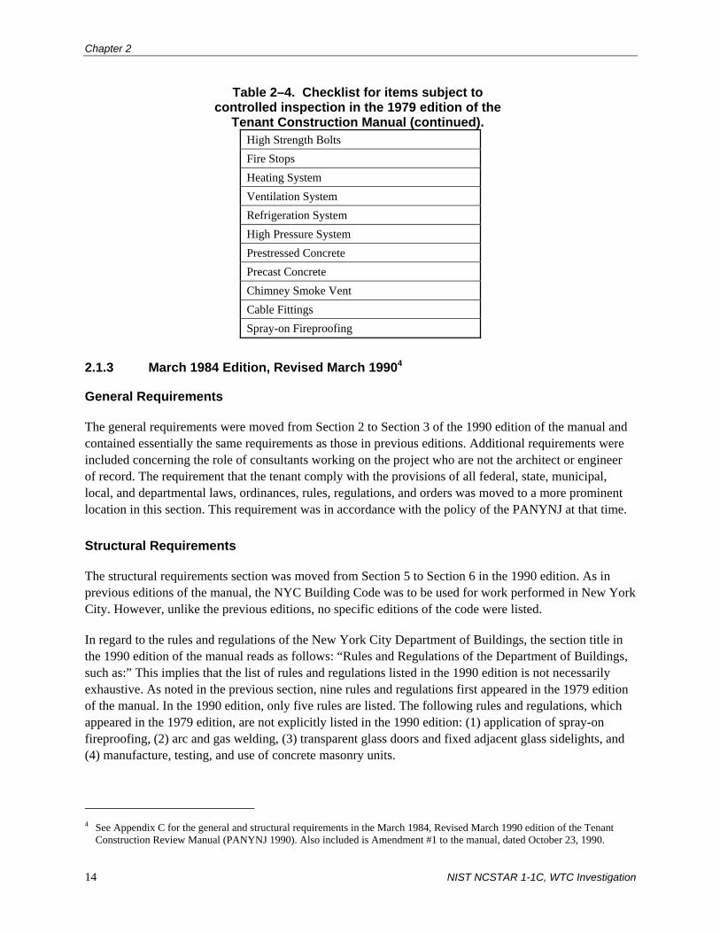
Chapter 2
14 NIST NCSTAR 1-1C, WTC Investigation
Table 2–4. Checklist for items subject to controlled inspection in the 1979 edition of the
Tenant Construction Manual (continued). High Strength Bolts Fire Stops Heating System Ventilation System Refrigeration System High Pressure System Prestressed Concrete Precast Concrete Chimney Smoke Vent Cable Fittings Spray-on Fireproofing
2.1.3 March 1984 Edition, Revised March 19904
General Requirements
The general requirements were moved from Section 2 to Section 3 of the 1990 edition of the manual and contained essentially the same requirements as those in previous editions. Additional requirements were included concerning the role of consultants working on the project who are not the architect or engineer of record. The requirement that the tenant comply with the provisions of all federal, state, municipal, local, and departmental laws, ordinances, rules, regulations, and orders was moved to a more prominent location in this section. This requirement was in accordance with the policy of the PANYNJ at that time.
Structural Requirements
The structural requirements section was moved from Section 5 to Section 6 in the 1990 edition. As in previous editions of the manual, the NYC Building Code was to be used for work performed in New York City. However, unlike the previous editions, no specific editions of the code were listed.
In regard to the rules and regulations of the New York City Department of Buildings, the section title in the 1990 edition of the manual reads as follows: “Rules and Regulations of the Department of Buildings, such as:” This implies that the list of rules and regulations listed in the 1990 edition is not necessarily exhaustive. As noted in the previous section, nine rules and regulations first appeared in the 1979 edition of the manual. In the 1990 edition, only five rules are listed. The following rules and regulations, which appeared in the 1979 edition, are not explicitly listed in the 1990 edition: (1) application of spray-on fireproofing, (2) arc and gas welding, (3) transparent glass doors and fixed adjacent glass sidelights, and (4) manufacture, testing, and use of concrete masonry units.
4 See Appendix C for the general and structural requirements in the March 1984, Revised March 1990 edition of the Tenant
Construction Review Manual (PANYNJ 1990). Also included is Amendment #1 to the manual, dated October 23, 1990.
Guidelines for Inspection, Repair, and Mod. to Structural Sys.
NIST NCSTAR 1-1C, WTC Investigation 15
A new subsection on Standards was added to the 1990 edition. The organizations whose standards are cited are: (1) American Association of State Highway and Transportation Officials and (2) American Railway Engineering Association.
The section containing Port Authority design criteria was significantly expanded. Most notably, all structures were required to be designed for earthquake zone 2 forces in accordance with the Building Officials Conference of America (BOCA) code. Local laws that contained seismic provisions more stringent than those in the BOCA code were to take precedence. Also, reference was made to American Society for Testing Materials (ASTM) E 580, Standard Practice for Application of Ceiling Suspension Systems for Acoustical Tile and Lay-in Panels in Areas Requiring Moderate Seismic Restraint for lightweight ceilings to resist seismic forces.
The checklist for structural review that appeared in earlier editions of the manual (see Table 2–1 and Table 2–3) was replaced; the 1990 edition of this list is summarized in Table 2–5.
Controlled Inspection of Materials, Operations, and Equipment
The inspection requirements, in Section 14 of the 1990 edition of the manual, were significantly reorganized and modified compared with those in the earlier editions of the manual. Like earlier editions of the manual, the NYC Building Code and its referenced standards were specifically referenced for the following requirements: (1) acceptance (approval) of materials, assemblies, forms, methods of construction, and (2) inspection of materials, assemblies, and construction.
Requirements for approval/acceptance of materials were abstracted directly from NYC Building Code Sections C26-106.1, 106.2, 107.1, and 107.2. No materials, assemblies, forms, method of construction, equipment, machinery, or devices were acceptable unless approved by the Code Test Method of the Materials and Equipment Acceptance (MEA) Division of the Office of the Commissioner of the Buildings Department of New York City or approved by the New York City Board of Standards and Appeals (BSA).
Controlled inspections requirements were abstracted from NYC Building Code Sections C26-106.3 and 107.3. All materials, equipment, and construction designated by the Code for controlled inspection were required to be inspected and/or tested to verify compliance with the Code. Controlled inspection was required to be made and witnessed by or under the direct supervision of a registered architect or professional engineer retained by the tenant and acceptable to the architect or engineer responsible for the plans. The inspecting design professional was to be independent of the design professional responsible for the work. The list of items subject to controlled inspection was essentially the same as the list in the 1979 edition (see Table 2–4), with the following exceptions: (1) steel (welding, high-strength bolts, and cable fittings) and formwork were added, (2) structural integrity during construction operations was added, and (3) Code section numbers and references to other resource documents were added for all items. Table 2–6 contains the list as it appeared in the 1990 edition of the manual.
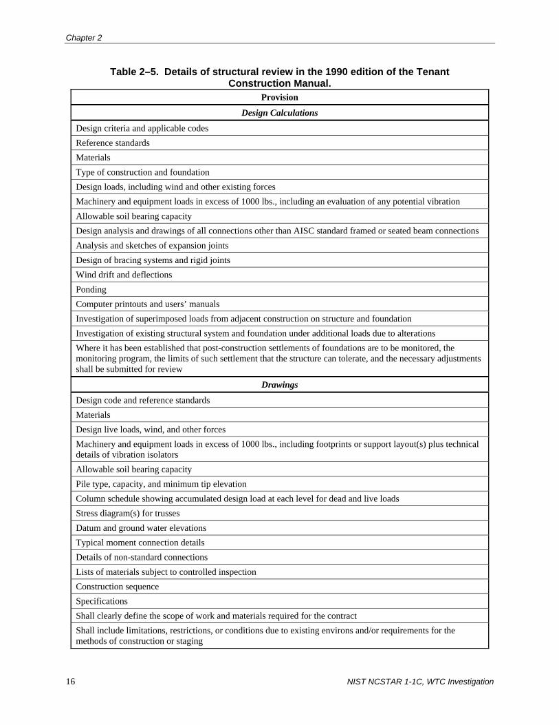
Chapter 2
16 NIST NCSTAR 1-1C, WTC Investigation
Table 2–5. Details of structural review in the 1990 edition of the Tenant Construction Manual.
Provision
Design Calculations
Design criteria and applicable codes Reference standards Materials Type of construction and foundation Design loads, including wind and other existing forces Machinery and equipment loads in excess of 1000 lbs., including an evaluation of any potential vibration Allowable soil bearing capacity Design analysis and drawings of all connections other than AISC standard framed or seated beam connections Analysis and sketches of expansion joints Design of bracing systems and rigid joints Wind drift and deflections Ponding Computer printouts and users’ manuals Investigation of superimposed loads from adjacent construction on structure and foundation Investigation of existing structural system and foundation under additional loads due to alterations Where it has been established that post-construction settlements of foundations are to be monitored, the monitoring program, the limits of such settlement that the structure can tolerate, and the necessary adjustments shall be submitted for review
Drawings
Design code and reference standards Materials Design live loads, wind, and other forces Machinery and equipment loads in excess of 1000 lbs., including footprints or support layout(s) plus technical details of vibration isolators Allowable soil bearing capacity Pile type, capacity, and minimum tip elevation Column schedule showing accumulated design load at each level for dead and live loads Stress diagram(s) for trusses Datum and ground water elevations Typical moment connection details Details of non-standard connections Lists of materials subject to controlled inspection Construction sequence Specifications Shall clearly define the scope of work and materials required for the contract Shall include limitations, restrictions, or conditions due to existing environs and/or requirements for the methods of construction or staging

Guidelines for Inspection, Repair, and Mod. to Structural Sys.
NIST NCSTAR 1-1C, WTC Investigation 17
Table 2–6. Checklist for items subject to controlled inspection in the 1990 edition of the Tenant Construction Manual.
Item Code Section or Resource Document Borings or Test Pits C26-1112.2 Piles C26-1112.3 Soil – Subgrade for foundation C26-1112.5 Controlled Fill – Underpinning C26-1112.6 Concrete Tables 10-1 and 10-2 Prestressed concrete – Precast concrete – Formwork C26-1904.3(b) Steel – welding, high strength bolts, and cable fittings
Table 10-2
Aluminum – welding Table 10-2 Laminated wood Table 10-2 Firestops C26-504.7(g) Spray-on fireproofing C26-502.2(f) Heating systems C26-1401.1(a) and 1401.2(b) Ventilation System C26-1301.2 and 1301.3 Refrigeration System C26-1301.4 High Pressure System – Chimney Smoke Vent C26-1501.1(e) and 1504.1(b) Exterior walls C26-150.1 Structural integrity during construction operations
Department of Buildings, Rules
2.1.4 March 1997 Edition5
General Requirements
The general requirements are essentially the same as those in previous editions of the manual.
Structural Requirements
The most notable change was made to the Port Authority design criteria section. The NYC Building Code was mandated to be used for earthquake design, subject to the modifications contained in Attachment S3. The modifications contained in this section pertain to Table 23-P, Horizontal Force Factor Cp of referenced standard RS 9-6, Earthquake Loads. The manual added horizontal force factors for overhead
5 See Appendix D for the general and structural requirements in the March 1997 edition of the Tenant Construction Review
Manual (PANYNJ 1997).

Chapter 2
18 NIST NCSTAR 1-1C, WTC Investigation
signs, anchorage for suspended ceilings weighing more than 4 psf without the weight of light fixtures, elevator and counterweight guardrails and supports, sprinkler piping, gas and high hazard piping, other piping, and heating, ventilation, and air conditioning (HVAC) ducts, along with new notes pertaining to sprinkler piping, other piping, and HVAC ducts. These requirements, which were originally outlined in a Port Authority Memorandum6 and which were included with other such requirements in the document Port Authority Standards Exceeding Code – Quality Assurance dated April 26, 1999 (PANYNJ 1999), were added to the manual to ensure that potential overhead hazards would not fall on building occupants during a seismic event.
The details of structural review in the 1997 edition were the same as those in the 1990 edition (see Table 2–5), except that the list of materials subject to controlled inspections was deleted.
Controlled Inspection of Materials, Operations, and Equipment
Some additions and modifications were made to the inspection requirements in the 1990 edition of the manual. The checklist for items subject to controlled inspection was also updated to include the updated NYC Building Code section numbers (see Table 2–7).
2.2 STANDARDS FOR STRUCTURAL INTEGRITY INSPECTION OF THE WORLD TRADE CENTER TOWERS A & B
2.2.1 Overview
In March of 1986, the Infrastructure Engineering Design Division of the Engineering Department of PANYNJ issued the Standards for Structural Integrity Inspection of the World Trade Center Towers A & B (PANYNJ 1986).7 These standards were to assist the PANYNJ in the evaluation of the structural integrity of WTC 1 and WTC 2 and were designed to anticipate structural degradation. If such degradation were to occur, the standards also contained provisions for repair.
Three methods were used to evaluate the structural integrity of the towers: (1) statistical inspections, (2) reports, and (3) continued measurements. In the first method, qualified outside consultants under PANYNJ management were to perform periodic visual inspection of selected structural components in “higher-potential trouble areas.” It was anticipated that PANYNJ in-house personnel would be able to perform such inspections in the future. The periodic inspections were to be supplemented by occasional visual inspections when the structure was exposed during tenant remodeling or general maintenance work.
In the second method, the evaluation would be based on problems identified in various reports. These reports may include maintenance reports of non-structural repairs, water leakage, and tenant complaints about unusual building movements, vibration, or noise.
6 PANYNJ Memorandum dated August 8, 1995 from Oscar Suros, Manager of the Engineering Department Quality Assurance
Division to Eugene J. Fasullo, Director and Chief Engineer (see Appendix G of this report). 7 See Appendix E for the complete document.

Guidelines for Inspection, Repair, and Mod. to Structural Sys.
NIST NCSTAR 1-1C, WTC Investigation 19
In the third method, the evaluation would be based on measurements of building movements or deformation using appropriate tests and instruments. Measurements were to be performed on individual components in the towers as well as on the entire towers themselves.
The periodic inspection program outlined in PANYNJ (1986) is adapted from “Standards for In-depth Structural Integrity Inspection of Buildings,” which was issued by the Engineering Department of PANYNJ in October of 1984 and which was relevant to any building owned and operated by the PANYNJ. The other sections in PANYNJ (1986) pertain exclusively to WTC 1 and WTC 2.
Table 2–7. Checklist for items subject to controlled inspection in the 1997 edition of the Tenant Construction Manual.
Item Code Section or Resource Document Borings or Test Pits 27-720 Piles 27-721 Subgrade for foundation 27-723 Controlled Fill 27-679(a) Underpinning 27-724 Concrete Tables 10-1 and 10-2 Formwork 27-1035(b) Steel – welding, high strength bolts, and cable fittings
Table 10-2
Aluminum – welding Table 10-2 Laminated wood Table 10-2 Firestopping 27-345(h) Masonry Table 10-2 Exterior Wall Insulation and Finish Systems
27-335.1(c)13
Spray-on fireproofing 27-324(f) Heating and combustion equipment
27-793(a), 27-794(b)
Ventilation System 27-779, 27-780 Refrigeration System 27-781 High Pressure System Department of Buildings, Rules Section 20-
02(b)(2)(i) Welding of gas distribution piping
RS-16, P115.8(h)
Chimney Smoke Vent 27-856(e), 27-879(b) Curtain/Panel Wall Rules of the City of New York, Title 1,
Department of Buildings, Chapter 32 Structural integrity during construction operations
Rules of the City of New York, Title 1, Department of Buildings, Chapter 16

Chapter 2
20 NIST NCSTAR 1-1C, WTC Investigation
2.2.2 Inspection Program
Visual Inspections
The PANYNJ recognized that the visual inspection of the entire structure, or even a major portion of it, in WTC 1 or WTC 2 was not practical, as stated in PANYNJ (1986). Thus, a statistical inspection program was implemented. This approach involved sampling those components and systems that were important to structural integrity at locations with “a relatively higher potential for occurrence of defects or problems.”
The inspection team was required to carry with them the following items: (1) a set of reduced drawings of the building(s), (2) field notebooks, (3) a camera, and (4) a tape recorder. Equipment, clothing, methods, and procedures were to conform strictly to PANYNJ safety regulations and to any applicable federal, state, or local regulations.
Visual inspection was to be supplemented by the use of simple hand tools, measurements, and recording techniques, as required. Loose, cracked, or rust-stained spray-on fireproofing and concrete or masonry encasement covering structural steel members and connections was to be removed prior to examining the steel. After inspection, any removed fire proofing was required to be properly replaced. Also, where it was necessary to drill a hole through a structural steel element to provide access for a borescope or any other device for inspection, the access hole was to be sealed with weld metal, body putty, or caulking, as appropriate.
Periodic inspection in WTC 1 and WTC 2 was to be performed by PANYNJ or its consultants on the following components at various time intervals, as noted below:
1. TV antenna mast on the top of WTC 1.
This program, the details of which are given in Appendix A of PANYNJ (1986), consisted of four parts: (a) inspection of the structural steel elements in the antenna, (b) inspection of the high tensile bolts and studs, (c) inspection of the weatherproof enclosure, and (4) inspection of the radomes. Inspection of these components was to be performed on a “continuing basis,” as weather and operational restrictions permitted. A complete inspection of the mast structure within the weatherproof enclosure was to be performed at least once a year; the other components were to be inspected at least once every 3 years.
The elements of the inspection program for the antenna mast, the high tensile bolts and studs, the weatherproof enclosure, and the radomes are given in Chapters II, III, IV, and V, respectively, of Appendix A (see Appendix E of this report).
2. Exterior roof and wall elements.
Every year, the exterior roof and wall elements were to be inspected for signs of water intrusion. Roof leakage was to be ascertained from an examination of the spaces immediately below the roof areas. Wall leakage was to be determined from signs of water staining of interior finishes.

Guidelines for Inspection, Repair, and Mod. to Structural Sys.
NIST NCSTAR 1-1C, WTC Investigation 21
3. Room occupancies.
An inspection of room occupancies and uses throughout both towers was to be performed on an annual basis to verify that design live load was not exceeded. A schedule of allowable live loads was to be maintained and updated as structural modifications were made. According to PANYNJ (1986), no such schedule existed at that time.
4. Accessible column envelopes, including fireproofing.
Every second year, accessible columns were to be inspected for bowing or deviation from plumb. Also, fireproofing was to be examined for signs of rust or cracking. Inspection for lateral displacement or rotation of columns in elevator shafts where the columns were braced on only one axis by connecting beams or concrete slabs was required. The location of these columns is given in Appendix C of PANYNJ (1986).
At Sublevel 5, the slabs on ground surrounding each column were to be examined for signs of rust or deformation.
5. Fireproofing and masonry partitions on diagonal bracing and transfer trusses.
Fireproofing and masonry partitions enclosing the diagonal bracing on exterior column lines in both towers below the Service Level Floor and the transfer trusses below floor 1 in WTC 2 under exterior and core columns were to be inspected every second year for cracking, stains, and other possible signs of structural distress.
6. Hat truss members.
Every second year, the hat truss members between floor 107 and the roof in the core area were to be inspected. Locations of these members are given in Appendix C of PANYNJ (1986).
7. Exterior box columns and spandrel plates.
Exterior box columns and spandrel plates under column trees below floor 7 were to be inspected every fourth year. Exterior aluminum covers and spray-on fireproofing were to be removed to gain access to the exterior surfaces of the box columns and spandrel plates. Both the columns and plates were to be visually inspected for bowing or distortion, cracking, and corrosion. Visual inspection was also required for accessible welds. Ultrasonic testing of full or partial penetration welds and adjacent base metal was to be performed where base metal thickness exceeded 1.5 in.
The interior of the box columns was to be examined by a borescope for the presence of water and the existence of rust on the interior plate surface. This was to be accomplished by drilling an access hole in the column or the spandrel plate at the locations noted in PANYNJ (1986).
The “tree” junction where the three superstructure columns merged was also to be inspected. The top surface of the horizontal diaphragm plate that capped the tapered box column just

Chapter 2
22 NIST NCSTAR 1-1C, WTC Investigation
below the point where the three separate columns merged was to be examined, as was the exterior column plate between this location and the column splice at elevation +372 ft 4 in.
8. Steel floor framing over mechanical spaces.
Every fourth year, the steel floor framing over mechanical spaces and other areas without suspended ceilings was to be inspected. No other details are given in the document.
9. Concrete slabs, partitions, and finishes.
Concrete slabs, partitions, and finishes were to be inspected every fourth year for signs of distress, which could indicate excessive structural deformation.
Occasional inspections were also to be made of the structural steel framing, connections, and the concrete slabs when general repairs or remodeling was done that involved removing ceilings, partitions, finishes, or other coverings. In particular, the top of the concrete slab was to be examined for cracking, spalling, and exposed or corroded top reinforcement. Where reinforcing bars were corroded and where concrete had spalled, repairs were to be made as tenant relocation permitted.
General maintenance reports and complaints from tenants were to be used to search for possible problems related to underlying structural defects. Water damage caused by leaks at the roof level or at the exterior walls, broken plumbing, and cracks in partitions or the concrete floor slab were to be reviewed to determine whether such events were caused by structural deformations. Records were to be kept of tenant complaints of building sway, floor vibration, sagging ceilings, unusual noise, and other items. Visual inspection of the appropriate area of the building was to be performed where a reasonable assessment of the data in the reports or logs was tied to a specific structural element or system. Reports and log data were to be correlated with testing and measurements described in Section B of Chapter IV in PANYNJ (1986), which is discussed in the next section of this report.
Periodic Measurements
Periodic measurements of various types of deformation and vibration were to be made for the purposes of monitoring changes in certain important characteristics of the buildings. Adverse changes in such measurements were assumed to reflect possible structural deterioration.
Measurements of the following items were to be performed on a periodic basis:
1. Natural frequency of the towers.
Accelerometers were to be installed on Mechanical floor 75 in WTC 2, one at each exterior wall near its midpoint (oriented to respond to horizontal displacements parallel to the wall) and two near the geometric center of the floor (to respond to displacements along the N-S and E-W axes of the building). Figure 1 in Appendix C of PANYNJ (1986) shows the location of the accelerometers (see Appendix E of this report).

Guidelines for Inspection, Repair, and Mod. to Structural Sys.
NIST NCSTAR 1-1C, WTC Investigation 23
The accelerometers in WTC 2, along with those already installed in WTC 1, were to be used to measure natural frequencies of the towers on a monthly basis. Wind speed and direction were also to be recorded at that time.
No documents reviewed indicate that accelerometers were installed in WTC 2.
2. Natural frequency of the TV mast on WTC 1.
Accelerometers and amplifiers were to be installed within the heated enclosure of the TV mast on the top of WTC 1 at a level of about two-thirds of the height of the mast above its base. One accelerometer was to be oriented to measure N-S displacements, and one was to be oriented to measure E-W displacements. Displacement measurements, as well as wind speed and direction, were to be recorded once a month.
No documents reviewed indicate that accelerometers were installed on the TV mast.
3. Natural frequency of the floor construction.
The natural frequency of the floor construction was to be measured when floor space had been emptied due to tenant change or remodeling. Figure 2 in Appendix C of PANYNJ (1986) shows the three zones outside of the core area on a typical floor (see Appendix E of this report): (1) corner zone (two-way floor trusses), (2) short-span zone (short-span floor trusses), and (3) long-span zone (long-span floor trusses).
In each tower, Mechanical floors 7, 41, and 75, and Tenant floors 9, 43, and 77, directly above the Mechanical Floors, were not included in the floor frequency measurement program, because they were framed with wide-flange steel beams and not trusses. However, these floors were to be inspected visually. It was also noted that Telephone Equipment Floors 10 through 13 in WTC 2, which were framed with floor trusses similar to typical tenant floors but were more heavily loaded than such floors, would have different dynamic characteristics in the three zones than would the corresponding zones in the tenant floors.
The natural frequency and damping values of the floor structure within a zone was to be measured by performing a “heel drop” test. In such tests, vibrations induced in the floor structure by a vertical impact are recorded using an accelerometer attached to the floor. Measurements were taken for an impact load of 100 lbs dropped from approximately 6 in. above the floor slab on to a 1 in. thick neoprene pad.
4. Viscoelastic dampers.
It was noted in PANYNJ (1986) that the testing program for the viscoelastic dampers should continue. This program consisted of continuously measuring and recording the movements of WTC 1 that were 3 in. or more. Wind speed and direction were also to be measured. It was anticipated that such measurements would continue until the end of 1985 or longer, depending on available funds.

Chapter 2
24 NIST NCSTAR 1-1C, WTC Investigation
Twelve viscoelastic damping units (four units from each of three floors) were to be removed from WTC 1 annually and were to be tested by the Minnesota Mining and Manufacturing Company, who were the manufacturers of the damping units. Temperature effects and shear strength were to be tested. See Chapter 3 of this report and the report titled Design and Construction of Structural Systems of WTC 1, 2, and 7 (NIST Special Publication 1000-6A) for more information on these tests.
A log of tenant complaints on noise and building sway was to be maintained on a continuous basis.
5. Plumbness and level.
Building plumbness and floor level checks were to be performed semiannually for each tower, preferably in the early morning hours in August when wind velocity was low and outside air temperatures were moderate.
Building plumbness was to be determined by measuring the offsets from a vertical laser beam, which was to be projected up from the bottom of freight elevator shaft 50, to the shaft walls. Offset measurements were to be taken at 20-story intervals.
Floor levelness was to be determined by measuring the relative elevation of sixteen benchmarks on the floor slab at floor 70 of each tower.
2.2.3 In-House Inspection Personnel
A list of duties, responsibilities, and minimum qualifications of the inspection supervisor, inspection crew leader, and inspection crew members from the PANYNJ is given in Chapter V of PANYNJ (1986).
The Supervisor of the Structural Integrity Inspection of the Buildings, who reported to the Engineer of Design, Infrastructure, was responsible for planning and directing the inspection, as well as preparing the inspection report. The Supervisor was required to have the following minimum qualifications:
• Professional Engineering License in New York or New Jersey specializing in structural engineering
• Five years of experience in responsible charge in structural design of buildings and 5 years experience in responsible charge in inspection of building construction, inspection of existing buildings, or maintenance of building structures.
The Supervisor did not have to conduct the inspection nor be present at the site at all times during the inspection. Rather, the Supervisor was to be familiar with the scope of the project and was expected to provide leadership and guidance. That person was also responsible for setting up and supervising any required training programs for inspection team members.
In addition to the general qualifications listed below for team members, crew leaders of the Inspection Team were required to have three years experience in responsible charge in inspection of building construction, inspection of existing buildings, or maintenance of building structures.

Guidelines for Inspection, Repair, and Mod. to Structural Sys.
NIST NCSTAR 1-1C, WTC Investigation 25
Field inspection crew members were expected to perform the required inspections without continuous supervision after initially receiving “moderate” guidance from the crew leader. The following qualifications were listed:
• Acute observation skills
• Common sense
• Strong motivation and persistence in carrying out any necessary follow-up procedures
As a minimum, an inspector should:
• Be able to climb steel and function comfortably at great heights and in difficult positions;
• Be a high school graduate or equivalent, with commensurate reading, verbal, and written communication skills;
• Be able to read and understand construction drawings and other documents;
• Be able to letter legibly and sketch technical details;
• Be able to operate a camera;
• Have a working knowledge of the use of measuring devices, such as rulers, tapes, gauges, protractors, and calipers; and
• Exhibit a proper concern for safety while inspecting.
PANYNJ (1986) also states that it was desirable, but not mandatory, that inspectors have some prior experience in related work, such as high steel construction, structural maintenance or inspection, or surveying.
2.2.4 Outside Consultants and Suppliers of Special Services
This section contains the requirements for outside consulting firms hired by the PANYNJ to perform periodic visual inspections or to accomplish tasks requiring special skills. The consulting firm was to assign a Supervisor who was a Professional Engineer licensed in New York or New Jersey and who possessed at least 5 years of experience in the design and field supervision of projects of comparable size and complexity. Field inspectors from the consulting firm were to have as a minimum the qualifications that were required for in-house inspectors, as outlined in Sec. 2.2.3 of this report.
The consulting firm was required to submit to the PANYNJ a list and description of comparable projects that were previously undertaken, and a list of the personnel, along with their qualifications and experience, who would be assigned to the inspection project.

Chapter 2
26 NIST NCSTAR 1-1C, WTC Investigation
2.2.5 Record Keeping and Follow-up Procedure
Defects and Signs of Distress
Chapter VII of PANYNJ (1986) lists the defects and signs of distress that were to be noted and recorded during inspection of the structural steel and the reinforced concrete. A summary is provided in Table 2–8.
Table 2–8. Defects and signs of distress to be recorded during inspection of WTC 1 and WTC 2.
Material Defect/Sign of Distress Description
Rust Rust was to be classified as follows: • Light – light, loose formation pitting the paint surface • Moderate – a looser formation with scales or flakes that have
formed • Severe – heavy, stratified rust or scale with pitting of the metal
surface. Net metal thickness and size of penetration, if any, was to be measured where pitting had occurred.
Cracks Cracks were to be classified as follows: • Fine • Medium • Open
The length, size, and location of any crack were to be recorded. Any crack was deemed to be potentially serious, and was required to be reported immediately.
Buckles and kinks
The type, location, and extent, and amount of deformation were to be recorded.
Connection and joint
Fine cracks in the paint at joints were deemed an indication of large strains due to stress concentrations. Records were to be made of the following:
• Sheared, missing, deformed, or loose bolts • Gusset plate deformations • Cracks in welds or in adjacent base metal
Alignment, excessive deflection, or bowing
Records were to be made of any floor truss, beam, or column that was misaligned, deflected, or bowing.
Structural Steel
Paint Paint was to be examined for cracking, chipping, rust pitting, and chalking.
Scaling Scaling was to be classified as light, medium, heavy, or severe. Records were to be made of the depth, extent, and location of the scaling.
Reinforced Concretea
Cracking Cracks were to be classified as follows: • Partial or through the member • Direction relative to framing or column lines • Horizontal, vertical, or diagonal • D-, map, or random
Records were to be made of the location, width, depth, and length of the cracking.

Guidelines for Inspection, Repair, and Mod. to Structural Sys.
NIST NCSTAR 1-1C, WTC Investigation 27
Spalling Spalls were to be classified as small, large, hollow area, joint spall, pop-out, or mudball. Records were to be made of the depth, size or extent, and location of the spalling.
a. Definitions of the defects and classifications as to degree of severity are referenced for reinforced concrete in the PANYNJ document Standards for In-depth Structural Integrity Inspection of Buildings, October 1984.
Source: PANYNJ 1986.
Inspection Records
Each component that was inspected was to be identified as follows:
• General location – building number and floor or floors
• Description label – column, beam, floor truss, viscoelastic damper, slab, etc.
• Piece mark and column designations at each end as applicable
• Type and location of affected part
The inspection record should include the description of the defect or distress. Measurements, sketches, and photographs were to be included in the record in those cases where a written description was not adequate. A tape recorder may also be used in addition to the written record.
If the Supervisor or the inspection team uncovered defects or indications of distress that appeared to require more than routine attention, a separate report of such findings was to be submitted to the Engineer of Design was to be immediately notified in person.
Three categories of urgency were established for repairs. Repairs falling into the “immediate” category included possible closure of the area and/or structure affected until interim remedial action (such as shoring or removal of a potentially unsafe element or structure) could be implemented. Such action was to be undertaken immediately after discovery, and a description of the action taken and recommendations for permanent repair were to be included in the inspection report.
The “priority” category was for those conditions where no immediate action was required, or for which immediate action had been completed, but for which further investigation, design, and implementation of interim or long-term repairs should be undertaken on a priority basis (i.e., taking precedence over all other scheduled work).
Repairs falling into the “routine” or “non-priority” category could be undertaken as part of a scheduled major work program or other scheduled project, or when routine facility maintenance was to be performed, depending on the type of repair that was required.
Measurements and Test Records
The measurements and test records section of PANYNJ (1986) outlines the various measurements and test data that were to be recorded during the inspection process for the items listed in Sec. 2.2.2 of this

Chapter 2
28 NIST NCSTAR 1-1C, WTC Investigation
report. Also given are the criteria that determine whether a possible problem may exist, based on the recorded measurements.
2.2.6 Excluded Work
In the last chapter of PANYNJ (1986) it was noted that the standards for structural inspection were applicable to only structural steel and reinforced concrete members in WTC 1 and WTC 2. Glass and glazing, facade panels, ceilings, partitions, elevators, stairs, and mechanical equipment were listed as components outside the scope of the document.
2.3 ARCHITECTURAL AND STRUCTURAL DESIGN GUIDELINES, SPECIFICATIONS AND STANDARD DETAILS
The document entitled Architectural and Structural Design Guidelines, Specifications and Standard Details was issued on February 27, 1998 by PANYNJ and contained architectural and structural design requirements for tenant alterations that were to be made specifically at WTC 1 and WTC 2 (PANYNJ 1998).8 The following discussion focuses on the structural requirements contained in this document.
2.3.1 Structural Design Guidelines
General
Prior to any design work, the tenant’s consultants were required to perform a field inspection of all areas that would be affected by the alterations so that the latest information was available for all structural elements, including, but not limited to truss reinforcement, stair openings in slabs, and core-hole locations.
The tenant’s consultants were required to submit calculations and construction drawings to PANYNJ for review and approval. All construction documents were required to be signed and sealed by a professional engineer or registered architect licensed to practice in the state of New York.
Calculations, Loads, and Design Parameters
For tenant alteration project, proposed floor loads were to be compared with the allowable design loads contained in Drawing STR-01 (see Appendix E). If the proposed floor loads would overstress the existing structural members, the floor system was allowed to be reinforced to carry the additional loads.
Calculations to compare the proposed loading with the allowable loads were required to conform to the latest edition of the NYC Building Code. Both allowable stress design and load-and-resistance-factor design were acceptable design methods.
The document recognized that portions of the corner floor areas would be able to carry greater loads than those shown in Drawing STR-01, due to the existing two-way truss system. Higher loads were allowed in
8 This document is contained in Appendix F of this report.

Guidelines for Inspection, Repair, and Mod. to Structural Sys.
NIST NCSTAR 1-1C, WTC Investigation 29
non-critical corner areas if it could be shown by analysis that such loads could be safely carried by the floor system.
The document required to show and locate on the construction drawings the weight of any equipment or cluster of equipment exceeding 500 lb and all files and shelves. In the latter case, a legend was to be shown on the drawings to indicate each type of file or shelving unit and the size and number of tiers for files and the height for shelves. Examples that show such weights on the construction documents can be found in Chapter 4 of this report.
Minimum loads to be used in the calculations were also specified. These loads are summarized in Table 2–9.
Table 2–9. Minimum loads specified for tenant alterations in PANYNJ Architectural and Structural Design Guidelines, Specifications, and Standard Details.
Item or Use Minimum Load File cabinets 33 psf per tier, including the weight of the cabinet Open shelves for paper storage 46 pcf of the net volume plus the weight of the
shelves Mechanized file storage Use manufacturer’s indicated fully loaded weight,
or the net weight of the storage unit plus 46 pcf for contents
Aisle loading for aisle width less than or equal to 30 in.
30 psf
Aisle loading for aisle width greater than 30 in.
60 psf
Reading areas 60 psf
Libraries
Open shelves 46 pcf of the net volume plus the weight of the shelves
Aisle width less than or equal to 30 in.
30 psf File rooms aisle loading
Aisle width greater than 30 in.
50 psf
Core Holes and Other Slab Penetrations
All proposed penetrations or drilling of cores in tower slabs were required to meet the criteria for location, spacing, and repair as specified in Drawings STR-02 through STR-08 (see Appendix F), and the section titled Structural Design Specifications, which is discussed below. As shown in the figures, there were some areas that were denoted as “prohibited” where no penetrations or cores were allowed, and there were some areas denoted as “restricted” where it was advisable not to locate penetrations or cores.
Hung Ceilings
For ceilings in the two-way truss areas of the towers, the size of the carrying channels and caddy clips were required to be larger than those required by the NYC Building Code, due to the long spans between

Chapter 2
30 NIST NCSTAR 1-1C, WTC Investigation
the trusses. The details in Drawings STR-09 through STR-14 (see Appendix F) were required to be provided on the construction drawings.
HVAC Equipment
The weight, dimensions, and location of all HVAC equipment were required on the drawings, including whether such units were floor mounted or hung from the framing above. Details for hanging ducts are in drawings HVAC-21 through HVAC-28. Calculations were required for all floor-mounted units showing that the existing framing would not be overstressed due to the weight of the equipment.
Walls
For walls over an opening, such as a door or other non-supportive materials, a lintel was required, or the wall was allowed to be suspended by studs from the framing above. In such cases, all connections were to be adequately designed for the loads.
Existing Steel
Holes were not allowed to be made in existing steel (beams, floor trusses, and columns) for hanging purposes, and welds were not allowed to be made to the trusses. Clamps approved by either the MEA Division of the Office of the Commissioner of the Buildings Department of New York City or by the New York City BSA were allowed.
2.3.2 Structural Specifications
Coring Criteria at Tower Power/Telephone Cells and Under Induction Units
The specifications given in the section on coring criteria were meant to supplement those given in the guidelines section, and were applicable to only those holes cored into the power/telephone cells and under induction units and only in the following typical tenant floors: (1) in WTC 1: floors 10 to 40, 45 to 74, and 78 to 105, and (2) in WTC 2: floors 14 to 40, 45 to 74, and 78 to 106.
The maximum core size allowed was 4 in. in diameter. The minimum average center-to-center spacing along a power/telephone cell for any 4 consecutive cored holes (including abandoned and filled holes) was 1 ft 4 in. Spacing criteria along power/telephone cells adjacent to holes offset from cells was provided in Drawing STR-05 (see Appendix F).
This section recommended avoiding cutting No. 4, No. 5, and No. 6 reinforcing bars in restricted zones. If such bars were to be cut, the bar repair details in Drawings STR-06 through STR-08 were to be followed (see Appendix F). As noted previously, coring was not allowed in prohibited zones, except within the induction units at the power/telephone cells only, which was considered a restricted area.
Rust, grease, and other contaminants were to be removed from structural steel and reinforcing bars prior to welding. All welders were to be qualified in accordance with the NYC Building Code and with other applicable laws and requirements.

Guidelines for Inspection, Repair, and Mod. to Structural Sys.
NIST NCSTAR 1-1C, WTC Investigation 31
This section required that all work conform to the latest edition of the NYC Building Code, including any revisions. Provisions in the latest editions of the following codes took precedence over those in the NYC Building Code whenever they were more stringent:
• American Institute of Steel Construction, Specification for the Design, Fabrication and Erection of Structural Steel for Buildings. Supplement 1 is specifically excluded.
• American Concrete Institute, Standard Building Code Requirements for Reinforced Concrete, ACI 318.
• American Welding Society (AWS), Structural Welding Code – Structural Steel (AWS D1.1) and Reinforcing Steel (AWS D1.4).
Any steel plates that were added to reinforce existing framing or for other reasons were required to conform to ASTM A36, and any reinforcing bars that were added were required to conform to ASTM A 615 Grade 60.
Welding materials for structural steel and reinforcing steel were required to be E7018 conforming to AWS A5.1 Specifications for Covered Carbon Steel Arc Welding Electrodes. Specifications for non-shrink grout were also specified.
Lightweight Ceiling Support System for Floors with Double Trusses
Specific proprietary concrete anchors were specified for any connections made to concrete. Other requirements were given for the type and sizes for clip angles, hangers, channels, and clamps. The contractor was to keep removal of fireproofing to a minimum and was to replaced removed fireproofing as “directed” by the Port Authority.
2.4 REFERENCES
PANYNJ (The Port Authority of New York and New Jersey). 1979. Tenant Construction Review Manual. (WTCI-134-P).
PANYNJ (The Port Authority of New York and New Jersey). 1986. Standards for Structural Integrity Inspection of the World Trade Center Towers A & B. Infrastructure Engineering Design Division, Engineering Department, The Port Authority of New York and New Jersey. (part of WTCI-66-P).
PANYNJ (The Port Authority of New York and New Jersey). 1990. Tenant Construction Review Manual. Engineering Quality Assurance Division, Engineering Department, The Port Authority of New York and New Jersey. (WTCI-132-P).
PANYNJ (The Port Authority of New York and New Jersey). 1997. Tenant Construction Review Manual. Engineering Quality Assurance Division, Engineering Department, The Port Authority of New York and New Jersey. (WTCI-131-P).

Chapter 2
32 NIST NCSTAR 1-1C, WTC Investigation
PANYNJ (The Port Authority of New York and New Jersey). 1998. Architectural and Structural Design Guidelines, Specifications, and Standard Details – Architectural, Structural. February. (WTCI-125-P).
PANYNJ (The Port Authority of New York and New Jersey). 1999. Port Authority Standards Exceeding Code – Quality Assurance. April. (WTCI-163-P).
PONYA (The Port of New York Authority). 1971. Tenant Construction Review. (WTCI-135-P).

NIST NCSTAR 1-1C, WTC Investigation 33
Chapter 3 STRUCTURAL INSPECTION PROGRAMS DURING THE OCCUPANCY OF
WTC 1, 2, AND 7
3.1 FACILITY CONDITION SURVEY REPORTS
The following facility condition survey reports, which include summaries on the condition of the structural systems in World Trade Center (WTC) 1, 2, and 7, were issued from 1990 to 2000 and are presented in chronological order.
3.1.1 Port Authority Facility Condition Survey Program – WTC 2
This section contains the findings of the condition survey of WTC 2 (Tower B), which was performed by the Engineering Quality Assurance Division (EQAD) of PANYNJ in 1990 (PANYNJ 1990).
Scope
The scope of the survey was based on recommendations made in Standards for Structural Integrity Inspection of World Trade Center Towers A & B (PANYNJ 1986). This document contains the minimum requirements of the periodic and occasional inspection programs that were to be implemented for WTC 1 and WTC 2. See Sec. 2.2 of this report for details on this document.
According to the facility condition survey report, the scope of work was designed to minimize impact on tenant and facility operations. Upon determination of minimum sampling sizes and inspection methods, EQAD performed a condition survey of structural and architectural elements. The following is a list of the structural elements that were inspected:
• Exterior wall system (including columns, spandrel plates, and connections)
• Core columns (including column splices and lateral bracing below the 7th floor; this part of the condition survey was primarily performed by the consulting firm Corddry, Carpenter, Dietz and Zack)
• Space frame (i.e., hat truss, including framing members and connections)
• Floor systems (including floor slabs and decks, trusses, rolled beams, bridging, and connections)
• Damping system (including damping units and connections)

Chapter 3
34 NIST NCSTAR 1-1C, WTC Investigation
Inspection Procedures and Methodology
To assess the condition of the structural system in the tower, EQAD performed both visual inspection and nondestructive testing methods. The thickness of steel members was checked using an ultrasonic thickness gauge. Fillet welds were tested for cracks and discontinuities using magnetic particle or dye penetration test methods, and groove welds were tested using the ultrasonic method.
Office Area Floors
The EQAD selected 30 office floors throughout the tower for inspection: 17, 18, 21, 27, 28, 29, 33, 34, 36, 37, 44, 45, 50, 55, 56, 62, 63, 64, 65, 74, 77, 82, 83, 90, 91, 92, 98, 100, 101, and 107. The following steps were taken when inspecting the structural elements at these levels:
1. Walk-through inspection with tenant representatives was performed to assess floor layout, determine operational areas that were important to the tenant, and select inspection locations.
2. A ceiling tile removal location plan was prepared for concealed spline ceilings.
3. Ceiling tiles were removed (performed by World Trade Department’s structural contractor).
4. Floor framing and steel decking, inside faces of steel spandrel plates, spandrel splices, ceiling components, utility supports, and window seals were visually inspected. Structural steel members covered with fireproofing were examined for signs of deformation or corrosion.
5. Approximately seven floor framing locations were selected for fireproofing removal and a removal location plan was prepared. In order to inspect column splices, two exterior columns were selected for plaster removal, both above and below the splice.
6. Fireproofing was removed at designated locations (performed by World Trade Department’s structural contractor).
7. An up-close inspection of exposed floor framing and column splices was performed for signs of cracking, deformation, or corrosion. Scrapers, wire brushes, and mirrors were used to accomplish this task.
8. Nondestructive testing was performed on column splice welds and welded floor framing connections (performed by the Materials and Research Division of PANYNJ, as directed by the Quality Assurance Division of PANYNJ).
9. Fireproofing and ceiling tiles were replaced, and plaster openings were repaired (performed by World Trade Department’s structural contractor).
Table 3–1 contains the percentage of structural elements inspected per office floor and for the entire tower.

Draft for Public Comment Structural Insp. Prog. During the Occupancy of WTC 1, 2, and 7
NIST NCSTAR 1-1C, WTC Investigation 35
Table 3–1. Percentage of structural elements inspected per office floor and for the entire tower per the 1990 Facility Condition Survey Report for WTC 2.
Element Type of Inspection Percentage per
Floor Percentage
Total Tower Visual 10 3 Fireproofing removal 4 1
Floor framing trusses
Nondestructive testing 2 0.5 Visual 8 3 Exterior column spandrel
plate splices Fireproofing removal 3 1 Exterior column splices Visual and nondestructive
testing 8 2
Mechanical Equipment Room (MER) and Space Frame
All four two-story MERs were visually inspected from the lower floor, which included inspection of floor framing and slab, interior columns, utility hangers and pads, and exterior setbacks. Concrete fireproofing for covering the steel floor framing was examined for delaminations and underlying corrosion.
Inspection of the space frame (hat truss) coincided with the 108th floor MER inspection. Fireproofing was removed from structural steel members and connections at several locations.
Core Columns
Core columns were inspected from the elevator shafts. This included visual inspection of (1) floor framing, columns, connections, and splices in 25 elevator shafts with fireproofing in place, (2) 10 eccentrically-braced column connections with fireproofing removed, and (3) 15 column splices with fireproofing removed.
Also, the core column lateral bracing at the first six floors was examined at two connection locations by removing the gypsum board firewall from the floor side. Nondestructive testing was also performed at some of the column splices.
Roof
The roof and appurtenant structures along with the Observation Deck were visually inspected. The roof framing and underside of the concrete roof slab were visually inspected from the 110th floor, and the top surface of the concrete roof slab and the roof parapet were visually inspected at random locations.
Findings of Inspection
The following sections summarize the findings and recommendations from the 1990 survey report.
Exterior Walls (Columns and Spandrels)
Inspection of the exterior walls was made from inside the building. Inspection locations are indicated in Fig. 3–1, which is Drawing 5 from the report (PANYNJ 1990).

36 N
IST N
CS
TAR
1-1C, W
TC Investigation
Chapter 3
Source: PANYNJ 1990. Reproduced with permission of The Port Authority of New York and New Jersey.
Figure 3–1. Typical inspection locations of exterior wall per 1990 Condition Survey Report of WTC 2.

Structural Insp. Prog. During the Occupancy of WTC 1, 2, and 7
NIST NCSTAR 1-1C, WTC Investigation 37
Floors 9 through 106—The exterior columns and spandrels were inspected on 30 floors at three areas of the wall panel: (1) column field splice connections, (2) spandrel field splice connections, and (3) inside spandrel plate face at the column/floor truss seat connections. Details of the splices at these locations are provided in Drawing 4 in the report, which is reproduced here in Fig. 3–2.
According to the report, exterior column splices were found to be in good condition.1 A total of 59 splices were inspected throughout 30 floors. At 49 of these locations, nondestructive testing was performed on the plate splice welds (see Sections a–a and b–b in Fig. 3–2 for location of welds), and ultrasonic testing was performed to verify plate thickness. Bolt tightness was also checked, and no loose bolts were found. However, on floors 74 and 77 (above and below an MER floor), the column splices had only three bolts, although the design detail called for four. According to the report, since the column splices at MER floors are groove welded, the missing bolts have no structural significance.
The inside faces of the steel box column plates were found to have scattered areas of light corrosion and peeling paint, as did splice bolts, welds, cap and base plates, and column stiffeners. Ultrasonic thickness testing on these outer column plates above and below the splice location indicated no section loss.
Fillet shop welds connecting the cap and base plates to the interior of the box columns were visually inspected at all open splice locations, and most of the welds were tested using the magnetic particle method. No cracking or significant discontinuities were detected at any location. According to the report, overlaps and undercuts were observed at several locations, but they were not significant enough to affect the performance of the connection.
Groove weld splices were tested on the 74th floor using the dye penetrant method and on the 77th floor using the magnetic particle method. No discontinuities or cracks were detected.
Spandrel plates, splice plates, and spandrel bolted connections were also found to be in good condition. Scattered rust stains were observed on the spandrel fireproofing, typically at the splice plates. All splice plate bolts were observed to be tight. Fillet welds at the truss seat connections to the spandrels were also found to be in good condition.
Floors 107 through 110—Inspection was limited to the joints at the 108th floor. No structurally significant deterioration was found.
Recommendations—No priority recommendations for repair were made in the report. It was recommended, however, that a long-term maintenance program be developed and implemented to clean and paint the inside surfaces of the exterior box columns to prevent further corrosion of the structural steel.
1 In this report, a structural member that receives a “good” condition rating requires no repairs. The structural member is
defined to be in “original condition” (see page 11 of PANYNJ (1990) for this and other definitions).

Chapter 3
38 NIST NCSTAR 1-1C, WTC Investigation
Source: PANYNJ 1990. Reproduced with permission of The Port Authority of New York and New Jersey.
Figure 3–2. Splice details at typical inspection locations of exterior wall per the 1990 Condition Survey Report of WTC 2.

Structural Insp. Prog. During the Occupancy of WTC 1, 2, and 7
NIST NCSTAR 1-1C, WTC Investigation 39
Core Columns
Inspection of the core columns was performed in two phases. In one phase, staff from the consulting firm of Corddry, Carpenter, Dietz and Zack inspected core columns from the elevator shafts. In the other phase, PANYNJ Quality Assurance Division staff inspected selected core corner columns from office area floors. They also inspected lateral core bracing at two locations from an elevator lobby on the 4th floor.
Core columns inspected from elevator shafts—The consultant randomly selected a total of 25 elevator shafts for inspection. Table B1 in the survey report contains a list of the elevator shafts that were visually inspected. Lateral bracing members, columns, and floor framing between the 2nd and 7th floors were inspected from eight other express elevator shafts.
Elevator core framing was inspected primarily with fireproofing materials in place. Only in elevator shaft number 52 between the 44th and 55th floors was the fireproofing removed at the column splices. According to the report, no defects were found in the existing fireproofing material. In most of the shafts, several small regions and a few large areas of fireproofing were found to be missing from core framing members, which, according to the report, was probably due to the high-speed elevators moving up and down the shafts. In particular, an 8 in. wide by 1 ft 6 in. long area of fireproofing was found to be missing on the top flange of the beam between shaft numbers 30 and 31 on floor 22. Also, 100 percent of the fireproofing was found to be missing from the south face of column 908 between floors 27 and 29 in shaft number 1. All exposed steel members were found to be in good condition with only isolated locations of light surface corrosion on the steel. Some minor shrinkage cracks were reported in the troweled-on fireproofing materials on the columns.
Gypsum wallboards surrounding the elevator shafts were also found to be in good condition, although isolated holes were detected at various locations as outlined in Table B2 of the survey report. At shaft number 4, a piece of wallboard was found to be loose in the southeast corner of the shaft; facility personnel repaired this piece.
Close-up inspection of column splices and eccentric-braced column connections with fireproofing removed at the locations designated in Tables B3 and B4 showed that all bolts, welds, and structural steel were in good condition. No defects in the welds were found after EQAD personnel performed ultrasonic tests on the butt welds at the column splices and magnetic particle tests on the fillet welds at the eccentrically-braced column connections.
Column splices and eccentrically-braced column connections in the express elevator shafts were not tested due to restricted access.
Quality Assurance personnel inspected the lateral bracing of the core columns at two locations (one between columns 606 and 607 and one between columns 907 and 908) on the 4th floor. Light surface corrosion was found on the bracing, splice plates, and bolts. The welds were tested using the magnetic particle method and were found to be in good condition, and no cracks were observed.
Core columns inspected from office area floors—Quality Assurance personnel inspected core corner columns at eight splice locations (see Table B6 in the survey report for locations). Seven of the splices were welded, and the welds were tested using the ultrasonic and magnetic particle methods. The eighth

Chapter 3
40 NIST NCSTAR 1-1C, WTC Investigation
location was a bolted splice connection. No defects were found in any of the welded splices. Steel columns exhibited light surface corrosion, as did the bolted splice on the bolts and splice plates.
Recommendations—No priority recommendations for repair were made in the report. It was recommended that the fireproofing that was missing from the elevator shaft framing members be replaced, including those regions where the fireproofing was removed for up-close inspection during the condition survey. This report also recommended that the holes in the gypsum wallboards surrounding the elevators, which are listed in Table B2 of the survey report, be repaired.
Floor Framing
Inspection locations for the floor framing at typical floors are shown in Drawing 9 of the report, which is reproduced here as Fig. 3–3. Findings for specific zones are reported below.
Main Lobby (floors 1 through 6)—Beams and connections that were inspected within the core in this zone were found to be in good condition. At various locations, fireproofing was missing, exposing light surface corrosion on the beams and connections.
Floors 9 through 41—Floor framing inspected in this zone was found to be in good condition. Light corrosion was observed on all core beams and beam connections, and on main truss connections on floors 28 and 37.
According to the report, the most significant deficiencies in this zone were found at the damping units (see Table C-1 in the survey report). Damping units on floors 18 and 37 were observed to be missing one fastener at each unit. Two fasteners were found to be missing in one damping unit on floor 29, as well as on floor 38. Also, at floor 38, a damping unit was observed to be missing four fasteners. According to the structural drawings (WSHJ 1967a), four fasteners were required to connect the damping unit to the member attached to the bottom chord of the floor truss, and two fasteners were required to connect the damping unit to the exterior column.

NIS
T NC
STA
R 1-1C
, WTC
Investigation 41
S
tructural Insp. Prog. D
uring the Occupancy of W
TC 1, 2, and 7
Source: PANYNJ 1990. Reproduced with permission of The Port Authority of New York and New Jersey.
Figure 3–3. Typical inspection locations of floor framing per the 1990 Condition Survey Report of WTC 2.

Chapter 3
42 NIST NCSTAR 1-1C, WTC Investigation
Floors 43 through 75—The floor framing in this zone was also found to be in good condition. Light corrosion was observed on the same members as in the previous zone.
Minor deficiencies were found at floor 64 and floor 75. A deformed bottom chord was found on the main truss along column 343 on the 64th floor. According to the report, “No signs of distress were observed.” The entire floor framing was visually inspected on the 75th floor, since the fireproofing was being replaced on this level. Most of the exposed structural components and connections were found to be in good condition. Untightened bolts were found at truss seat connections at several locations, which, according to the report, did not significantly affect the structural integrity of the framing.
Hairline cracks were observed in the 2 in. thick concrete topping slab near the south exterior wall on the 44th floor. According to the report, these cracks were due to shrinkage and did not affect the structural integrity of the floor slab.
Floors 77 through 107—The floor framing in this zone was found to be in good condition, with light surface corrosion observed on all core framing beams and connections.
Minor deficiencies were found in floor slabs, where separation of the concrete slab from the metal deck forms was found at floors 93 and 108. According to the report, this condition did not affect the structural integrity of the slab, since decking served as formwork for the concrete and had no structural function.
Mechanical Equipment Rooms (Floors 7–8, 41–42, 75–76, 108–109)—The floor framing and slab inspected on the MER floors were found to be in good condition. On all MER floors, most of the structural framing was inaccessible due to heating, ventilation, and air conditioning (HVAC) ducts, fans, electrical equipment, or plumbing. No nondestructive testing was performed on these levels.
Hairline cracks were found in concrete beam encasement at various locations on all four MER floors. Exposed steel exhibited light surface corrosion, and no deterioration was found at the underside of floor slabs.
Selected elements of the space frame at various locations on the 107th through 110th floors were inspected and were found to be in good condition. Exposed truss elements and connections both exhibited light surface corrosion. Bolted and welded connections were also found to be in good condition.
Recommendations—No priority recommendations for repair were made in the report. As mentioned above, all the deficiencies found were considered to have no significant effect on structural integrity. It was recommended that utility supports found to be bowed or vibrating be replaced as part of the facility’s regular maintenance program.
Roof
Roof framing, which consisted of rolled steel wide flange beams supporting a structural concrete slab, was found to be in good condition. Hairline cracks in the fireproofing and in the underside of the concrete slab were found at various locations.
Recommendations—No priority recommendations for repair were made in the report. Recommendations that were made were not structural in nature.

Structural Insp. Prog. During the Occupancy of WTC 1, 2, and 7
NIST NCSTAR 1-1C, WTC Investigation 43
3.1.2 Port Authority Facility Condition Survey Program – WTC 1
This section contains the findings of the condition survey of WTC 1 (Tower A), which was performed in 1991 by the Office of Irwin G. Cantor, Consulting Engineers, for the EQAD of PANYNJ (PANYNJ 1991).
Scope
The scope of the survey was determined based on experience gained from the condition survey of WTC 2 in 1990, which was discussed in Sec. 3.1.1 of this report.
The scope of work was designed to minimize impact on tenant and facility operations, and was limited to vacant floors and tenant areas and partially occupied floors. The following is a list of the structural elements that were inspected:
1. Floor framing (long, short, and transverse trusses, rolled beams, concrete encased beams, bridging, and connections)
2. Damping system (damping units from bottom of trusses to exterior walls and connections)
3. Exterior wall system (columns, column splices, spandrel plates, splices, and bolted connections of spandrel beams)
4. Core columns (columns within elevator shafts, including visible floor beams)
5. Space frame (framing members and connections)
6. Mechanical equipment room (framing, machinery bases and utility supports, and exterior offsets)
7. Roof (slab, window washer rails, top façade, antenna bases, and window wash concrete walls)
Inspection Procedures and Methodology
To assess the condition of the structural system in the tower, both visual inspection and nondestructive testing methods were employed. The thickness of steel members was checked using an ultrasonic thickness gauge. Welds were tested using magnetic particle and/or dye penetration test methods.
Office Floor Areas
Fourteen office floors (11, 13, 22, 30, 35, 52, 54, 61, 65, 78, 84, 86, 90, and 93) throughout WTC 1 were selected for inspection. Inspection of the structural elements at these levels followed the following sequence:
1. Six long-span trusses and two short-span trusses were selected from the plans for even, random distribution of inspection locations throughout the floor area.

Chapter 3
44 NIST NCSTAR 1-1C, WTC Investigation
2. Floor framing, damping unit, utility supports, steel decking, inside faces of steel spandrel plates, spandrel splices, and core concrete or rolled steel members were visually inspected. Structural steel members were examined for signs of deformation or corrosion with fireproofing still in place.
3. The following locations for fireproof removal were selected and submitted: (a) six truss locations, (b) one core floor beam, (c) two spandrel plate splices, and (d) two exterior columns (plaster removal).
4. The 11 locations listed above were inspected up close, using lights, scrapers, wire brushes, and mirrors for signs of cracking, deformation, or corrosion. Photographs were taken of typical conditions and “Remarks” were documented.
5. Nondestructive testing was performed on column splice welds and welded floor framing connections. Testing was performed by either the Port Authority’s Materials and Research Division or by Lucius Pitkin, Inc.
On 2 of the 14 floors inspected, column splices on seven core columns were inspected after removal of the gypsum board firewalls. Top sides of exposed concrete floor slabs were also inspected where carpeting or floor tiles had previously been removed.
Table 3–2 contains the number of structural elements inspected per office floor.
Table 3–2. Number of structural elements inspected per office floor per the 1991 Facility Condition Survey Report for WTC 1.
Element Type of Inspection Quantity Visual 22 Fireproofing removal 6
Floor framing trusses
Nondestructive testing 4.3 (avg.) Visual 6 Exterior column spandrel
plate splices Fireproofing removal 2 Exterior column splices Visual and Non-
destructive testing 2
MER and Space Frame
All four two-story MERs were visually inspected from the lower floor and accessible upper floor levels. Floor framing, slabs, interior columns, and utility hangers and pads were inspected. Concrete fireproofing for covering the steel floor framing was examined for delaminations and underlying corrosion.
At the 107th and 108th floors, fireproofing was removed at nine locations. Of these, seven were welded connections that were tested by the magnetic particle method.
Core Columns
Core columns were inspected from the elevator shafts in addition to the corner core column splices that were inspected from the two office area floors. The elevator shaft inspections included visual inspection

Structural Insp. Prog. During the Occupancy of WTC 1, 2, and 7
NIST NCSTAR 1-1C, WTC Investigation 45
of floor framing, columns, connections, and splices in 13 elevator shafts with fireproofing in place. Core column connections to floor beams in the core were also examined.
Roof
The roof concrete slab top surface and parapet were visually inspected, along with the roof framing and underside of the concrete roof slab.
Findings of Inspection
The following sections summarize the findings and recommendations from the WTC 1 survey report.
Exterior Walls (Columns and Spandrels)
Floors 9 through 106—Exterior column splices were found to be in good condition.2 A total of 28 column splices were inspected throughout the 14 office floors. At 26 of these locations, nondestructive testing was performed on all of the splice welds and the box column plates; each test showed that the welds were in good condition. Ultrasonic testing was performed to verify thickness of the spandrel plates. These tests showed no loss of thickness. Tightness of the bolts in the spandrel beam splices was also checked, and no loose or missing bolts were found.
The inside faces of the steel box column plates exhibited scattered areas of light to moderate corrosion3 and peeling paint. Light corrosion was also found at splice bolts, welds, cap and base plates, and diaphragms. Ultrasonic thickness testing on these outer column plates above and below the splice location indicated no section loss.
Fillet shop welds connecting the cap and base plates to the interior of the box columns were visually inspected at all open splice locations. No cracking or significant discontinuities were detected at any location.
Spandrel plates, splice plates, and bolted connections were also found to be in good condition. Scattered corrosion stains were observed on the spandrel fireproofing, typically at the splice plates and along the lower edges of the floor slabs. All splice plate bolts were observed to be tight. Fillet welds at the truss seat connections to the spandrels were also found to be in good condition.
A summary of the findings is contained in Table A-2 in the survey report, which is reproduced here as Table 3–3.
Floors 107 through 110—Inspection of the exterior walls was limited to the joints at the 108th floor. No structurally significant deterioration was found. Joint sealer in the column cladding was missing at nearly all of the 59 column seals.
2 In this survey report, a structural member that receives a “good” condition rating requires no repairs. The structural member is
in “original condition” (see page 14 of PANYNJ (1991) for this and other definitions). 3 In this survey report, “corrosion” and “rust” are used interchangeably. See page 15 of PANYNJ (1991) for a definition of
corrosion.
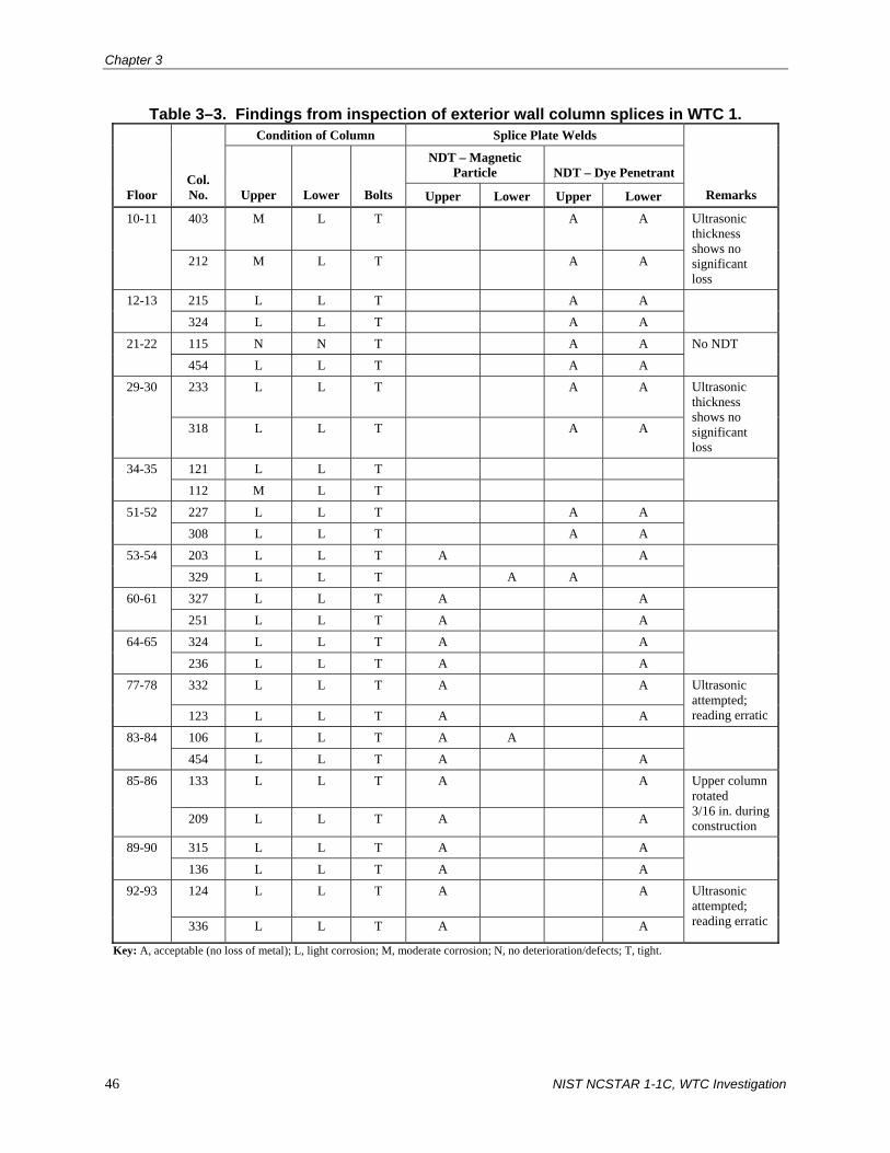
Chapter 3
46 NIST NCSTAR 1-1C, WTC Investigation
Table 3–3. Findings from inspection of exterior wall column splices in WTC 1. Condition of Column Splice Plate Welds
NDT – Magnetic Particle NDT – Dye Penetrant
Floor Col. No. Upper Lower Bolts Upper Lower Upper Lower Remarks
403 M L T A A 10-11
212 M L T A A
Ultrasonic thickness shows no significant loss
215 L L T A A 12-13
324 L L T A A
115 N N T A A 21-22
454 L L T A A
No NDT
233 L L T A A 29-30
318 L L T A A
Ultrasonic thickness shows no significant loss
121 L L T 34-35
112 M L T
227 L L T A A 51-52
308 L L T A A
203 L L T A A 53-54
329 L L T A A
327 L L T A A 60-61
251 L L T A A
324 L L T A A 64-65
236 L L T A A
332 L L T A A 77-78
123 L L T A A
Ultrasonic attempted; reading erratic
106 L L T A A 83-84
454 L L T A A
133 L L T A A 85-86
209 L L T A A
Upper column rotated 3/16 in. during construction
315 L L T A A 89-90
136 L L T A A
124 L L T A A 92-93
336 L L T A A
Ultrasonic attempted; reading erratic
Key: A, acceptable (no loss of metal); L, light corrosion; M, moderate corrosion; N, no deterioration/defects; T, tight.

Structural Insp. Prog. During the Occupancy of WTC 1, 2, and 7
NIST NCSTAR 1-1C, WTC Investigation 47
Recommendations—No priority recommendations for repair were made in the report. It was noted, however, that missing fireproofing should be replaced on the spandrel plates and splices, and that the joints in the aluminum cladding should be resealed where the seals were removed.
Core Columns
Inspection of the core columns was performed in three phases:
• Core columns were inspected from the elevator shafts.
• Seven core column splices were inspected from unoccupied office areas.
• Core floor beam to column connections were inspected at 25 of 56 locations on 14 floors.
Core columns inspected from elevator shafts—Inspection of the core columns in an elevator shaft was performed from the top of the elevator cab.
Thirteen elevator shafts (four express elevator shafts and nine local elevator shafts) were randomly selected for inspection with the concurrence of Port Authority personnel. The shafts that were selected for inspection can be found in Table B-1 of the report, which is reproduced here as Table 3–4.
Table 3–4. Visual inspection of elevator core framing in WTC 1. Elevator Shaft
Number Floors Inspected Adjacent Column Number Remarks
2 1 – 44 907, 1007 11 1 – 44 901, 1001 12 1 – 78 501, 601 15 1 – 78 503, 603 26 9 – 16 708, 807 35 17 – 24 706, 805 43 33 – 40 702, 802 52 46 – 54 708, 807 62 55 – 61 706, 805 67 62 – 67 702, 802 77 80 – 87 708, 807 80 79 – 87 806, 907 90 93 – 101 703, 803
No fireproofing removed
In the express elevator shafts, beams framing in the north-south direction were typically encased in concrete. Steel in the other direction consisted of built-up welded box girders and columns with sprayed-on fireproofing. According to the report, no defects were found in the fireproofing that would suggest a problem with the steel columns, bracing, and floor framing. However, several small areas and a few large areas of fireproofing were missing from the steel girders and columns. It was suggested in the report that the small areas of exposure were caused by (1) the mounting of brackets and other hardware to support conduit and guide cables and (2) the movement of hoist cables that were rubbing the shaft girder.

Chapter 3
48 NIST NCSTAR 1-1C, WTC Investigation
According to the report, the probable cause of missing fireproofing on box columns was thought to be the forces induced by the high speed of the elevators moving up and down the shafts. All exposed steel was found to be in good condition with light to medium surface rust. Gypsum closure wallboards were found to be in good condition, except for isolated holes in two elevator shafts at the 58th and 69th floors (see Table B-2 in the survey report, which is reproduced here as Table 3–5). The report states that these openings represent a fire safety hazard that should be corrected.
Table 3–5. Locations of holes in gypsum wallboard around elevators in WTC 1. Elevator Shaft Number Floor Number
62 58 12 69 12 58
Local elevator shafts typically had wide-flange columns and girders with sprayed-on fireproofing. Fireproofing was found to be missing on some of the steel members where there was contact with hoist cables and where the steel served as staging support for maintenance workers servicing electrical conduits. The exposed steel was found to be in good condition with light surface rust. Steel beams supporting the elevator door saddles were encased in concrete, except for a few beams that were found to be partially encased (for example, in one case, concrete was missing from the bottom flange of one of the steel beams). The report states that the fireproofing should be replaced in these cases. The gypsum closure walls were also found to be in good condition except for a few isolated holes and/or projections into the shaft (see Table 3–5).
Core corner columns inspected from office area floors—Core corner columns were inspected at all four corners of the 92nd to 93rd floors and at three corners at the 77th to 78th floors. All seven locations were inspected by removing the five or more layers of gypsum wallboard around the splice locations, which were 3 ft 0 in. above the finished floor level.
On the 92nd to 93rd floors, all four splices were bolted connections. No defects were found at any of the bolted splices. Welded splices were found at all three locations on the 77th to 78th floors, and were tested using the dye penetrant method. Results from the tests showed that there were no surface cracks in the welds. Steel plates, bolts, and welds that were visible were found to have only light surface corrosion.
Core column to floor beam connections inspected from office floors—Twenty-five floor beam to column connections were visually inspected, and seven connections were inspected up-close throughout the tower (see Table B-3 in the report for locations, which is reproduced here as Table 3–6). No deformations were found in any of the connections that could be inspected. No inspection occurred where firewalls obstructed vision or where heavy beams supported minor beams. Either no or light corrosion was found on the exposed steel.

Structural Insp. Prog. During the Occupancy of WTC 1, 2, and 7
NIST NCSTAR 1-1C, WTC Investigation 49
Table 3–6. Core column connection inspection in WTC 1. Number of Beam to Column
Connections Inspected
Floor Number Visually Up close with
fireproofing removed Corrosion Deformation
10-11 3 1 L N 12-13 4 4 N N 21-22 0 0 – – 29-30 4 0 N N 34-35 3 0 L N 51-52 0 0 – – 53-54 1 0 L N 60-61 2 0 L N 64-65 0 0 – – 77-78 0 0 – – 83-84 0 0 – – 85-86 2 0 L N 89-90 4 1 L N 92-93 2 1 L N
Totals 25 7
Key: L, light; N, none.
Recommendations—No priority recommendations for repair were made in the report. It was recommended that the fireproofing that was missing from the elevator shaft framing members be replaced, including those regions where the fireproofing was removed for up-close inspection during the condition survey. It was also recommended that the holes in the gypsum wallboards surrounding the elevators, which are listed in Table B-2 of the survey report be repaired.
Floor Framing
Inspection locations for the floor framing were divided into three elevator zones: (1) Zone 1 (floors 9 through 41), (2) Zone 2 (floors 43 through 75), and (3) Zone 3 (floors 77 through 107).
Office floors, trusses—Typical floor framing was inspected from below at five locations in Zone 1, four locations in Zone 2, and five locations in Zone 3. Fireproofing was removed at various locations on each floor that was inspected to provide up-close examination of the framing components and connections. Welds were tested at most of these locations using either the magnetic particle method or dye penetrant.
Two typical conditions were observed during inspection. First, small areas of fireproofing were missing at scattered locations throughout the floor framing. Second, the underside of the bottom plates of the seated connections of the trusses exhibited light rust. According to the report, this was the result of the welding process that had occurred above the plate, which heated the paint, causing it to fall off. No structural deficiency was noted due to this condition.

Chapter 3
50 NIST NCSTAR 1-1C, WTC Investigation
At all locations that were examined, the damping units were not covered with fireproofing. Small amounts of light rust were observed throughout. Also, the damping unit under the 30th floor was missing a non-structural bolt.
In some cases, the connection of the truss to the exterior spandrel plate did not have the typical two-bolt connection. Instead, the seat had one bolt and a weld. It is suggested in the report that the bolt holes may not have lined up during erection, so welding was used instead. These field welds were tested by either the magnetic particle or dye penetrant method, and were “found to be functioning properly.”
On the 10th and 61st floors, diagonal members of bridging trusses were removed in order to allow 2 ft wide by 1 ft deep HVAC ducts to pass through parallel to the floor trusses. According to the report, the bottom chords of the bridging trusses were attached to the adjacent trusses “so that there was no decrease of structural integrity.” No details are provided in the report on how these connections were made.
Office floors, metal deck—The metal deck was inspected from below at 22 locations per floor. No significant rust was observed because, according to the report, the metal deck was galvanized. However, in an area of approximately 500 ft2 on the underside of the 84th floor, a scattering of light rust was observed through the fireproofing.
Office floors, concrete slab—In the core areas, the underside of the cast-in-place concrete slab was observed to be in good condition. A 4 in. by 4 in. area was spalled under the 11th floor, and a 6 in. by 6 in. by 2 in. deep spall was noted under the 54th floor. Also, a construction joint was found to be open south of columns 505 and 504 under the 13th floor.
Concrete slabs were also inspected from above at locations where floor tiles or carpeting were previously removed. In general, the slabs in the office floors were found to be in good condition, except for the slab at the southeast corner of the 60th floor. In this area, cracks were found, which formed at a 45 degree angle with the corner. Over a period of 4 months, the cracks did not open any further than originally measured. It was also observed that concrete slabs in the office areas were damaged by construction and removal of office partitions. Spalls resulting from nails being removed from the slab were noted on floors without tile or carpeting.
Table C-1 and C-2 in the survey report, which are reproduced here as Table 3–7 and Table 3–8, respectively, provide a summary of the locations and observations of the inspection for the trusses, connections, welds, secondary members and connections, damping units, and metal deck.
Recommendations—No priority recommendations for repair were made in the report for any of the floor framing members. Routine recommendations were made as follows: (1) patch elastomeric sealer at the construction joint south of columns 504 and 505 under the 13th floor, (2) even though the modifications made to the bridging trusses at the 10th and 61st floors did not meet the original design, no further modifications were needed, (3) patch spalls that were created in concrete slabs when partition rails were removed, and (4) patch cracks on the 60th floor with elastomeric sealer.

Structural Insp. Prog. During the Occupancy of WTC 1, 2, and 7
NIST NCSTAR 1-1C, WTC Investigation 51
Table 3–7. Floor framing and slab inspection results for WTC 1. Weld Test
Floor Level
Outer Framing – Main
Trusses, Beams Connections
Column Line
Test Condition
Secondary Members and Connections
Damping Units
Metal Deck
Underside
ZONE 1
11 G G 155, 303, 443 G G L G
13 G G 305, 353, 421 G G L G
22 G G 123, 131, 331, 335 G G L G
30 G G, L 141, 423 G G L G 35 G G, L 121, 133 G G L G
ZONE 2
52 G, L G, L G, L G
54 G, L G, L 151, 351, 353, 421 G G
61 G, L G, L 243, 331, 305 G G L G
65 G, L L 157, 319, 423 G G L G
ZONE 3
78 G, L L 131, 243 G G, L L G
84 G, L G, L 103, 107, 113, 121 G G L G
86 G, L G, L 131, 151, 217 G G L G
90 G, L G, L 135, 243, 319 G G L G
93 G, L G, L 117, 307, 443 G G L G
Key: G, good condition; L, light corrosion.
MER and Space Frame
A 100 percent visual inspection was performed on all four mechanical equipment rooms (floors 7–8, 41–42, 75–76, and 108–109). According to the report, most floor framing was inaccessible due to the presence of HVAC ducts, fans, electrical piping, and plumbing equipment.
Mechanical Equipment Rooms—According to the report, the floor slabs at these levels were determined to be in good condition. Scattered cracks ranging in width from 1/16 in. to 1/8 in. were found on the slab surfaces. The report suggests that previously repaired cracks were found to be deteriorated due to load and vibration. Cracks were also found in equipment pedestal supports and column encasement.

Chapter 3
52 NIST NCSTAR 1-1C, WTC Investigation
Table 3–8. Core framing inspection results for WTC 1. Floor Level Beams Beam Connection Underside of Slab
ZONE 1
11 G, L G, L G 13 G, L G, L G 22 G G, L G 30 G, L G, L G 35 L L G, L
ZONE 2
52 L L G, L 54 L G, L G 61 G, L G, L G 65 L L G
ZONE 3
78 G, L G G 84 G, L G G 86 L G, L G 90 L G, L G 93 L L G
Key: G, good condition; L, light corrosion.
Scattered patches of spray-on fireproofing were found to be missing from the metal decks, which were used in the perimeter areas (i.e., areas outside the core area). These areas had light rust visible on the underside of the metal deck. Concrete encasement on the steel beams in the core area was found to be in good condition with hairline cracks at scattered locations. In a few places, the encasement had spalled off of the steel beams, which exposed the welded wire fabric in the encasement and portions of the steel beams. The exposed steel was found to have a light coating of rust.
Visual inspection of the beam to column connections found them to be in good condition, according to the report. Exposed steel members exhibited only light surface corrosion where fireproofing was removed on floors 108 through 109.
A concrete encased beam at the 110th floor was subjected to steam from a leaking steam valve. Moderate rusting was confirmed on the member, and, according to the report, no discernible section loss was found.
Hangers supporting ducts, piping, etc., were also visually inspected. Hangers subject to excessive vibration, loose hanger rods, and the fatigue of pipe supports were found at various locations. According to the report, beams that supported the duct hangers had fireproofing missing where the hangers were mounted.
Detailed findings on the MER levels are shown in the four floor plans on pages 41 through 44 of the 1991 Facility Condition Survey Report for WTC 1.

Structural Insp. Prog. During the Occupancy of WTC 1, 2, and 7
NIST NCSTAR 1-1C, WTC Investigation 53
Space Frame—Selected elements of the space frame (hat truss) were inspected at various locations on the 107th to 110th floors. A total of 75 diagonal bracing members were visually inspected without removing fireproofing. A total of 199 members were inspected in the space frame. Light rust was found on diagonal braces, beams, and connections where fireproofing was missing.
Recommendations—A priority recommendation was made in the report to replace the leaking valve under the 110th floor that rusted the floor beam. Routine recommendations were made as follows: (1) Repair the surface cracks in the MER concrete floor slabs with a surface sealer, (2) Repair the cracks in the concrete at the base of the columns, (3) Repair the cracks in the concrete pads supporting mechanical equipment, (4) Patch and repair the spalled concrete encasement of all appropriate structural members, and (5) Repair hangers that were found to be vibrating, bowed, sagged, and/or deformed.
Roof
A visual inspection of the top surface of the concrete roof deck and concrete wall at the inner perimeter of window washing rails was performed, and no significant structural deficiencies were found. Cracking and spalling was found at localized areas of the roof. Some of the spalled areas that had been previously patched with grout were found to be in poor condition due to exposure to weather.
Horizontal cracks and efflorescence, spalled concrete, and exposed reinforcing bars with minor corrosion were found at the exterior walls of the access stairway located at the roof. The report suggests that the spalling of the concrete was due to inadequate concrete cover over the reinforcing bars.
The helicopter pad at the southeast corner of the roof was visually inspected and was found to be in good condition. No deficiencies were found in the bases of the antennas, all of which were visually inspected.
Recommendations—No priority recommendations were made for the roof. Routine recommendations were made as follows: (1) Remove and replace the existing patches in the roof slab using a bonding agent and non-shrink grout as a replacement and (2) Patch spalled areas of exterior concrete curb of the access stairway located at the roof. Other routine recommendations in the report were not structural in nature.
3.1.3 Port Authority Facility Condition Survey Program – WTC 7
The Port Authority Facility Condition Survey Program – WTC 7 report contains the findings of the condition survey of WTC 7, which was performed by Ammann & Whitney in 1997 for the EQAD of PANYNJ (PANYNJ 1997).
Scope
The scope of work was designed to minimize impact on tenant and facility operations, and was limited to (1) unoccupied floors, which were the mechanical/electrical and general service floors (floors 3 through 6), and (2) floors that had vacant space (floors 7, 10, 18, 23, and 25). The following is a list of the structural elements that were inspected:
1. Foundation
2. Framing (column splices, wind bracing systems, and interior beam connections)

Chapter 3
54 NIST NCSTAR 1-1C, WTC Investigation
3. Floor slabs
4. Con Edison Substation
Inspection Procedures and Methodology
The inspection was primarily a visual inspection, with “hands-on” inspection4 of approximately 5 percent of the “critical connections.” A field inspection team visually inspected the structural elements noted in the previous section. Inspections were performed from the floor level and from ladders. A manlift was required to inspect the lobby and trading floor ceilings.
Column Splices
Table III-1 in the report, which is reproduced here as Table 3–9, contains the inspection point locations for the column splices in interior and exterior columns.
Table 3–9. Column splice inspection points in WTC 7.
Floor
Number of Inspection
Points Column Numbers Location of Connection
INTERIOR COLUMNS
5 3 58C (H), E3, & 79 See Drawing S-3 23 6 58(H), 59, 63(H), & 79–81 See Drawing S-8
EXTERIOR COLUMNS
10 46–55 North side 9 19–27 South side 5 26, 7(H), 39–41 East side 5 2, 3, & 12–14 West side
5
2 Hangers 25A & 26 South side 23 1 25 West side
Key: (H), hands-on inspection performed at these locations.
Wind Bracing System
Tables III-2 and III-3 in the report, which are reproduced here as Tables 3–10 and 3–11, respectively, contain the inspection point locations for columns and girders that were part of the lateral-force-resisting system.
Interior Beam Connections
Table III-4 in the report, which is reproduced here as Table 3–12, contains the inspection point locations for the interior beam connections.
4 What constituted hands-on inspection is not described in the report (PANYNJ 1997).

Structural Insp. Prog. During the Occupancy of WTC 1, 2, and 7
NIST NCSTAR 1-1C, WTC Investigation 55
Table 3–10. Wind inspection points, columns, in WTC 7.
Floor
Number of Inspection
Points Column Numbers Location of Connection
CORE
1 4 64–73 North side
2 4 64–73 North side
LOWER EXTERIOR
10 43, 46–54 North side
4 25, 26, 27(H), 28(H) South side
3 28(H), 29, 30 East side
5
4 12 – 14A West side
2 28–29 East side 6
3 6–8 West side
UPPER EXTERIOR
1 29 East side 23
1 12 West side Key: (H), hands-on inspection performed at these locations.
Table 3–11. Wind inspection points, girders, in WTC 7.
Floor
Number of Inspection
Points Column Numbers Location of Connection
5 3 16–19A South side
8 46–54 North side
1 55–56(H) North side
8 19–27 South side
1 27–28(H) South side
5 28–30, & 38–41 East side
6
4 2–3 & 12–14A West side
2 23–25 South side 8
2 28–30 East side
5 21–26 South side 19
1 26–27(H) South side
4 44–46 & 53–55 North side
3 25–28(H) South side
1 35–36(H) East side
24
2 5–6 & 9–10 West side
1 42–43(H) North side
3 32–33, & 37–39 East side
1 41–42 East side
44
1 5–6 West side
1 57–1(H) North side Main Roof
1 4–5 West side Key: (H), hands-on inspection performed at these locations.

Chapter 3
56 NIST NCSTAR 1-1C, WTC Investigation
Table 3–12. Interior beam connection inspection points in WTC 7.
Floor
Number of Inspection
Points
5 5 6 4 8 6
11 6 19 5 24 10 26 7 44 2
Main roof 5
Findings of Inspection
According to the report, the structural framing was found to be in good condition.5 No problems or deterioration were found on the column splices, wind bracing, or the interior beam connections.
Rust buildup was found between the flanges of members that rested on top of one another at the main roof level where the steel framing was exposed. Although this was not considered to be a structural problem, it was recommended that the steel should be cleaned and painted to prevent further deterioration.
Throughout the building, fireproofing was found to be missing from the steel framing at locations where utility supports were installed. This condition was found on all of the floors that were inspected, but it was most prominent on the 5th floor framing above the main lobby and the 2nd floor framing above the loading dock area. The report recommended in the report that the fireproofing be replaced.
Loose concrete was found on the north face of column number 51 on the 46th floor of the cooling tower area.6 Due to the potential hazard immediate action was recommended. Silverstein Properties personnel immediately removed the loose concrete.
Floor slabs were found to be in good condition. Some of the exposed floor slabs exhibited shrinkage cracks on the top sides, and some had the composite metal deck damaged during construction. Neither of these conditions was considered to pose a structural problem. The report also recommended that delaminated concrete be removed at the concrete patch in the 6th floor slab.
A complete list of the recommendations made in the report for immediate action, safety items, and routine repairs is reproduced in Fig. 3–4.
5 In this report (PANYNJ 1997), “good condition” means that the element is sound and performing its functions although it
shows signs of use and may require some minor repairs, mostly routine. 6 No information is given in PANYNJ (1997) on the size or exact location of this loose concrete.

Structural Insp. Prog. During the Occupancy of WTC 1, 2, and 7
NIST NCSTAR 1-1C, WTC Investigation 57
The report also noted that the Con Edison station was in very good condition and that no action was required at that time.
Source: PANYNJ 1997. Reproduced with permission of The Port Authority of New York and New Jersey.
Figure 3–4. Recommendations made in the 1997 Facility Condition Survey Report for WTC 7.

Chapter 3
58 NIST NCSTAR 1-1C, WTC Investigation
Source: PANYNJ 1997. Reproduced with permission of The Port Authority of New York and New Jersey.
Figure 3–4. Recommendations made in the 1997 Facility Condition Survey Report for WTC 7 (continued).
3.1.4 Due Diligence Physical Condition Survey – WTC 1 and WTC 2
The Due Dilligence Physical Condition Survey – WTC 1 and WTC 2 report contains the findings of the condition survey of WTC 1 and WTC 2, which was performed by Merritt & Harris, Inc. in 2000 for PANYNJ (Merritt & Harris 2000).

Structural Insp. Prog. During the Occupancy of WTC 1, 2, and 7
NIST NCSTAR 1-1C, WTC Investigation 59
Scope
On-site evaluations were performed to assess the general physical condition of the property, as it existed at that time. In particular, WTC 1, WTC 2, WTC 4, WTC 5, the retail mall and plaza, central services, and the subgrade were inspected. The following discussion focuses on the findings for WTC 1 and WTC 2.
Inspection Procedures and Methodology
Observations were limited to those portions of the project that were visible during walk-through. In many areas, building finishes concealed structural components from view. The consultant neither took material samples nor performed tests on the building materials or systems.
Findings of Inspection
The following findings and recommendations were reported for both WTC 1 and WTC 2.
According to the report, the building structure appeared to be in good overall condition, based on observations of portions of the structure that were not concealed by building finishes. No apparent movement or settlement of foundations was observed, and interior slabs were reported to be in good condition.
The report notes that Leslie E. Robertson Associates (LERA) and other engineering firms had performed, on a regular basis, Structural Integrity Inspections (SII) of various structural systems and that those studies have indicated the following deficiencies: (1) rusting of steel columns in the elevator shafts, (2) missing fireproofing, and (3) floor coring damage. The due diligence condition survey report goes on to note that the most recent SII recommended repairs were underway at the time the report was written.
Damping units had been tested every 5 years, most recently in 1996. The report notes that approximately two-dozen damping units were kept in stock for replacement. The report also states that LERA strongly recommended that the analysis of wind acceleration measurements be continued.
The report notes that an ongoing program of re-fireproofing structural steel members was in place at the time of the inspection. Re-fireproofing the structural steel was supposed to provide a two-hour fire rating for those members. Such work was performed on an entire floor when the space was being built-out for new occupancy. At the time of inspection by Merritt & Harris, Inc., approximately 30 floors had been completed in the two towers.
3.2 STRUCTURAL INTEGRITY INSPECTION PROGRAM
3.2.1 Overview
In 1986, the PANYNJ implemented an inspection program to detect, record, and correct any signs of distress, deterioration, or deformation that could signal structural problems for WTC 1 and WTC 2 (PANYNJ 1986). This program for structural integrity, which was based on an inspection and testing plan prepared by LERA, contained detailed guidelines on inspection, record-keeping, and follow-up procedures. It included periodic inspection intervals for the TV antenna mast, exterior roof and wall elements, room occupancies and uses, accessible columns, fireproofing envelopes, bracing truss members

Chapter 3
60 NIST NCSTAR 1-1C, WTC Investigation
between floor 107 and the roof (hat truss), steel floor framing, and concrete slabs. Details of the SII program are presented in Sec. 2.2 of this report, including the required follow-up procedures, which are outlined in Sec. 2.2.5.
Inspection findings under the SII program were to be categorized as “Immediate,” “Priority,” or “Routine.” Findings requiring “immediate action” would include possible closure of the area and/or structure until interim remedial measures (such as shoring or removal of a potentially unsafe element or structural member or members) could be implemented. “Priority” findings addressed those conditions for which no immediate action was required or for which immediate action has been completed, but for which further investigation, design, or implementation of interim or long-term repairs should be undertaken on a priority basis, i.e., taking precedence over all other scheduled work. For “routine” or non-priority cases, further investigation and/or remedial work could be undertaken as part of a scheduled major work program or routine facility maintenance. Where inspection procedures involved the removal of fireproofing, such fireproofing was to be properly replaced on completion of inspection.
In January of 1990, LERA submitted a proposal to the PANYNJ for monitoring the structural integrity of the World Trade Center Complex.7 The proposal contained the scope of testing and inspection services for WTC 1, WTC 2, WTC 4, WTC 5, WTC 6, the Vista Hotel, and the subgrade and was based on a modified and expanded version of the 1986 action plan that was previously submitted to PANYNJ.
The scope of services presented in the proposal included three separate approaches to identifying potential component and/or system degradation:
1. Statistical Inspections – Periodic statistical testing and inspection of structural components in areas that had a higher potential for trouble.
2. Review of Reports – Examination of maintenance reports (e.g., nonstructural repairs, water leakage, and tenant complaints about building movements and/or vibration) for indications of possible structural degradation.
3. Continued Measurements – Evaluation of the performance of structural systems through continued measurement of movement and deformations using appropriate tests and instruments.
The program called for inspection or monitoring of the following items, among other things, in WTC 1 and WTC 2:
1. TV mast (WTC 1 only)
2. Roof water tightness and curtain wall
3. Space usage
7 Letter dated January 12, 1990 from Saw-Teen See of Leslie E. Robertson Associates to Suren Batra of the Port Authority of
New York and New Jersey (WTCI-123-P; see Appendix G of this report).

Structural Insp. Prog. During the Occupancy of WTC 1, 2, and 7
NIST NCSTAR 1-1C, WTC Investigation 61
4. Accessible columns, including exterior box columns at locations of spandrel intersections and “tree” junctions below floor 7 and above floor 1 (Plaza Level)
5. Bracing at exterior column line below elevation 294 ft 0 in., and in WTC 2 only, the transfer trusses below floor 1 under exterior columns
6. Hat truss between floor 107 and the roof
7. Floor framing over mechanical spaces
8. Concrete slabs, partitions, and finishes
9. Steel framing, slabs, and the like where exposed for general repairs or tenant remodeling
10. Measurement of natural frequency of tower and TV mast
11. Floor natural frequency
12. Damping units
13. Plaster ceilings in main lobby
14. Marble wall panel supports
15. Review of maintenance reports
16. Fire stairs
Inspection and monitoring of these items were proposed to occur at regular intervals. Estimated manpower and cost estimates based on proposed inspection intervals were also given, and are shown here in Fig. 3–5. A detailed inspection program outlining the steps required for visual inspections and periodic measurements was also contained in the proposal.
3.2.2 Summary of Structural Integrity Inspection Program Reports
LERA and other engineering firms conducted periodic inspections of the towers under the WTC Structural Integrity Inspection Program, which was based on the proposal originally submitted to PANYNJ by LERA in 1990. The following sections of this report summarize the findings from the SII Program reports related to the structural aspects of the towers.
The PANYNJ has reported that the construction records on repairs following the SII reports were destroyed when the towers collapsed on September 11, 2001. In addition, the PANYNJ has reported that any missing fireproofing that was identified in the SII reports to be repaired was done so on a routine basis.

Chapter 3
62 NIST NCSTAR 1-1C, WTC Investigation
Space Usage Surveys
The purpose of the space usage surveys was to identify possible structural overloading of the slabs and floor framing due to changes in occupancies and uses and/or due to additions of heavy equipment or furniture. The inspections were conducted by a walk-through by LERA personnel on predetermined floors within WTC 1 and WTC 2. Such usage surveys were initially proposed to be conducted annually on an ongoing basis (see Fig. 3–5). Surveys actually were conducted annually over a five-year period starting in 1995 (two surveys were conducted in 1996). A summary of the findings from the space usage reports is contained in Table 3–13.
Accessible Columns
Surveys of the accessible columns (columns in the core area that were not enclosed by an architectural finish, which can be visually inspected) in the elevator shafts of WTC 1 and WTC 2 were performed to:
• Ascertain the condition of the accessible columns with respect to rusting, cracking, bowing, and deviation from plumb
• Identify specific locations of structural distress or damage
• Identify locations of damage to the fireproofing
• Identify lateral displacement or rotation of the column about a vertical axis where the column was directly braced on only one axis by connecting beams or concrete slabs
• Identify deformations of the slabs-on-ground surrounding each column at the sublevel.
Accessible column surveys were proposed to be performed every two years on an ongoing basis (see Fig. 3–5). As seen in Table 3–14, which contains a summary of the findings from the accessible columns reports, the proposed inspection schedule was not followed exactly. See Appendix G of this report for the exact locations where the columns were inspected over the height of both towers in all of the SII reports.

Structural Insp. Prog. During the Occupancy of WTC 1, 2, and 7
NIST NCSTAR 1-1C, WTC Investigation 63
Source: PANYNJ 1990. Reproduced with permission of The Port Authority of New York and New Jersey.
Figure 3–5. Estimated manpower and cost estimates for structural integrity inspections for WTC 1 and WTC 2.

Chapter 3
64 NIST NCSTAR 1-1C, WTC Investigation
Source: PANYNJ 1990. Reproduced with permission of The Port Authority of New York and New Jersey.
Figure 3–5. Estimated manpower and cost estimates for structural integrity inspections for WTC 1 and WTC 2 (continued).
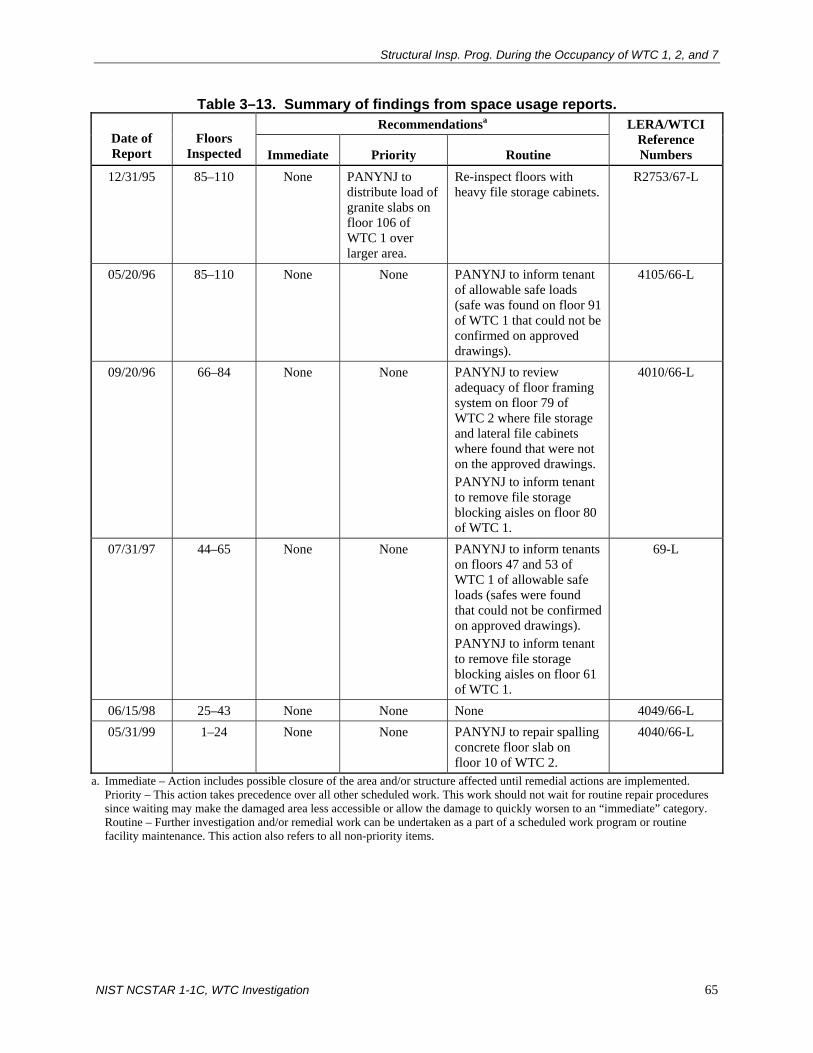
Structural Insp. Prog. During the Occupancy of WTC 1, 2, and 7
NIST NCSTAR 1-1C, WTC Investigation 65
Table 3–13. Summary of findings from space usage reports. Recommendationsa
Date of Report
Floors Inspected Immediate Priority Routine
LERA/WTCI Reference Numbers
12/31/95 85–110 None PANYNJ to distribute load of granite slabs on floor 106 of WTC 1 over larger area.
Re-inspect floors with heavy file storage cabinets.
R2753/67-L
05/20/96 85–110 None None PANYNJ to inform tenant of allowable safe loads (safe was found on floor 91 of WTC 1 that could not be confirmed on approved drawings).
4105/66-L
09/20/96 66–84 None None PANYNJ to review adequacy of floor framing system on floor 79 of WTC 2 where file storage and lateral file cabinets where found that were not on the approved drawings. PANYNJ to inform tenant to remove file storage blocking aisles on floor 80 of WTC 1.
4010/66-L
07/31/97 44–65 None None PANYNJ to inform tenants on floors 47 and 53 of WTC 1 of allowable safe loads (safes were found that could not be confirmed on approved drawings). PANYNJ to inform tenant to remove file storage blocking aisles on floor 61 of WTC 1.
69-L
06/15/98 25–43 None None None 4049/66-L 05/31/99 1–24 None None PANYNJ to repair spalling
concrete floor slab on floor 10 of WTC 2.
4040/66-L
a. Immediate – Action includes possible closure of the area and/or structure affected until remedial actions are implemented. Priority – This action takes precedence over all other scheduled work. This work should not wait for routine repair procedures since waiting may make the damaged area less accessible or allow the damage to quickly worsen to an “immediate” category. Routine – Further investigation and/or remedial work can be undertaken as a part of a scheduled work program or routine facility maintenance. This action also refers to all non-priority items.

Chapter 3
66 NIST NCSTAR 1-1C, WTC Investigation
Table 3–14. Summary of findings from accessible columns reports. Recommendationsa Date of
Report Immediate Priority Routine LERA/WTCI
Reference Numbers
01/29/93 None None PANYNJ to repair all spalled and missing fireproofing on the columns.
4078/66-L
04/14/95 None None PANYNJ to properly clean and repair fireproofing on all exposed steel (columns and connecting beams) at many or all of the floor levels that were inspected. PANYNJ to clean and repair all corroded steel in elevator pits due to water damage.
4079/66-L
05/17/96 None PANYNJ to test damaged (cause unknown) beam webs in elevator shaft 34B in WTC 2 below floors 9 and 10. PANYNJ to add new web stiffeners to these beams as a minimum.
PANYNJ to repair deteriorated fireproofing on columns and connecting beams throughout all of the shafts inspected in accordance with Appendix E of the SII report. PANYNJ to repair drywall in elevator shaft 95A, floor 100 in WTC 1. PANYNJ to repair fireproofing at base of columns in elevator pits in all of the shafts that were inspected. PANYNJ to reduce cable sway using a cable damping system in all of the shafts that were inspected. PANYNJ to investigate fire rating of damaged shaft wall in elevator pit 61B in WTC 2 at floor 42.
4004/66-L
05/23/97 None PANYNJ to repair deteriorated fireproofing on column 905 between floors 35–41 in WTC 2 in accordance with Appendix E of the SII report.
PANYNJ to repair deteriorated fireproofing on all of the columns, connecting beams, and elevator pits throughout all of the shafts that were inspected in accordance with Appendix E of the SII report.
4004a/66-L

Structural Insp. Prog. During the Occupancy of WTC 1, 2, and 7
NIST NCSTAR 1-1C, WTC Investigation 67
Table 3–14. Summary of findings from accessible columns reports (continued). Recommendationsa Date of
Report Immediate Priority Routine LERA/WTCI
Reference Numbers
05/30/98 None PANYNJ to repair deteriorated fireproofing on columns on floors 2–17 and 29-40 in WTC 1 in accordance with Appendix D of the SII report. PANYNJ to replace fireproofing that is missing over the entire height of floor 48 in elevator shaft 68A in WTC 1. PANYNJ to replace missing fireproofing on column 902 in elevator shaft 9B at floors 10, 18, and 34; on column 803 in elevator shaft 47B at floors 4 and 31; and, on column 805 in elevator shaft 94B at floor 77 in WTC 2.
PANYNJ to repair deteriorated fireproofing on columns and connecting beams throughout all of the shafts that were inspected in accordance with Appendix E of the SII report. PANYNJ to reduce cable sway using a cable damping system in all of the shafts that were inspected. PANYNJ to repair fireproofing at base of columns in elevator pits that were inspected per Appendix D in the SII report.
4050/66-L
a. Immediate – Action includes possible closure of the area and/or structure affected until remedial actions are implemented. Priority – This action takes precedence over all other scheduled work. This work should not wait for routine repair procedures
since waiting may make the damaged area less accessible or allow the damage to quickly worsen to an “immediate” category. Routine – Further investigation and/or remedial work can be undertaken as a part of a scheduled work program or routine facility
maintenance. This action also refers to all non-priority items.
Plaza Level Box Columns
The purpose of the inspection of the Plaza Level box columns was to assess their overall structural integrity, including the condition of the fireproofing. As can be seen from Fig. 3–5, the proposed inspection interval was four years. One such inspection was performed in April of 1998. The east face of WTC 1 and the north face of WTC 2 were visually inspected between the Concourse Level ceiling and the underside of the Plaza Level slab. The columns between the Concourse floor level and ceiling level were inaccessible due to their enclosures.
A summary of the findings from the Plaza Level box columns report is given in Table 3–15. The report notes that fireproofing was missing from approximately 2–3 percent of the Plaza Level box columns and seated beam connections in WTC 1 and about 1–2 percent in WTC 2.

Chapter 3
68 NIST NCSTAR 1-1C, WTC Investigation
Table 3–15. Summary of findings from Plaza Level box column report. Recommendationsa Date of
Report Immediate Priority Routine LERA/WTCI
Reference Numbers
05/08/98 None None PANYNJ to clean all exposed steel on Plaza Level columns 236, 242, and 248 in WTC 1 and repair damaged fireproofing on columns and seated beam connections in both towers.
4002/66-L
a. Immediate – Action includes possible closure of the area and/or structure affected until remedial actions are implemented. Priority – This action takes precedence over all other scheduled work. This work should not wait for routine repair procedures since
waiting may make the damaged area less accessible or allow the damage to quickly worsen to an “immediate” category. Routine – Further investigation and/or remedial work can be undertaken as a part of a scheduled work program or routine facility
maintenance. This action also refers to all non-priority items.
Bracing below Elevation 294 ft 0 in.
Below Elevation 294 ft 0 in. (Sublevel 1) in both WTC 1 and WTC 2, diagonal bracing was used in place of deep spandrels between the exterior columns to resist lateral loads from the tower above. The purpose of the inspection of the bracing system in the perimeter walls of the towers was to:
• Assess the overall performance and structural integrity of the bracing (and, in 1991 only, the transfer trusses below elevation 310 ft 0 in. in WTC 2);
• Identify specific locations of structural distress or damage;
• Identify locations of damage to the structural fireproofing systems; and
• Provide recommendations for remedial work for both structural and fireproofing damage.
As can be seen from Fig. 3–5, the proposed inspection interval was two years, which is less than the actual inspection interval shown in Table 3–16. The 1995 SII report notes that the only prior inspection of the bracing was done on October 31, 1991. Also, the 1995 SII report recommended that future inspections should be performed every two years, with particular attention given to corrosion and fireproofing. In both the 1991 and 1995 SII reports, it is noted that the observed thickness of the fireproofing on the bracing members was between 0.25 in. and 1 in.
It is evident from Table 3–16 that the PANYNJ did not complete action on a number of “routine” category recommendations from the 1991 report. Remedial work for these recommendations was to be carried out as part of a scheduled maintenance program. Such recommendations include draining of flooded areas due to water leaks was not fully accomplished, and repairs to the connections between the braces and the columns were not made. Fireproofing was not applied to the transfer truss between columns 242 and 248 at the B1 Level in WTC 2. Also, fireproofing was not repaired on some of the bracing members at Level B6 and at other levels. It appears that all of the damaged concrete masonry unit (CMU) walls acting as fireproofing, which were identified in the 1991 SII report, were repaired; many additional CMU walls were noted for repair in the 1995 SII report.

Structural Insp. Prog. During the Occupancy of WTC 1, 2, and 7
NIST NCSTAR 1-1C, WTC Investigation 69
Table 3–16. Summary of findings from bracing reports. Recommendationsa Date of
Report Immediate Priority Routine LERA/WTCI
Reference Numbers
10/31/91 None None PANYNJ to drain flooded areas due to water leaks in Level B6 of WTC 1 and WTC 2. PANYNJ also to repair any corroded steel and welds at the connections of the bracing members to the columns due to flooding and to reapply fireproofing after painting all steel with a zinc-rich paint. PANYNJ to clean, repair, and reinstall fireproofing on structural members at Level B6 in the Mechanical Equipment Rooms of both towers. PANYNJ to repair CMU walls that serve as fireproofing at various locations in WTC 1 and WTC 2 as noted in the report. PANYNJ to repair all spray fireproofing on the braces in WTC 1 and WTC 2 and the transfer truss in WTC 2 between columns 242 and 248 at the B1 Level.
4096/66-L
03/01/95 None None PANYNJ to drain flooded areas due to water leaks in Level B6 of WTC 1 and WTC 2. PANYNJ also to repair any corroded steel and welds at the connections of the bracing members to the columns due to flooding and to reapply fireproofing after painting all steel with a zinc-rich paint. PANYNJ to clean, repair, and reinstall fireproofing on structural members at Level B6 in the Mechanical Equipment Rooms of both towers. PANYNJ to repair CMU walls that serve as fireproofing at various locations in WTC 1 and WTC 2 as noted in the report. PANYNJ to repair all spray fireproofing on the braces in WTC 1 and WTC 2 and the transfer truss in WTC 2 between columns 242 and 248 at the B1 Level.
4066/66-L
a. Immediate – Action includes possible closure of the area and/or structure affected until remedial actions are implemented. Priority – This action takes precedence over all other scheduled work. This work should not wait for routine repair procedures
since waiting may make the damaged area less accessible or allow the damage to quickly worsen to an “immediate” category. Routine – Further investigation and/or remedial work can be undertaken as a part of a scheduled work program or routine facility
maintenance. This action also refers to all non-priority items.
The 1995 SII report notes that large areas of fireproofing on the structural steel members were removed or damaged due to the February 1993 bombing of WTC 1. During reconstruction of this area, fireproofing

Chapter 3
70 NIST NCSTAR 1-1C, WTC Investigation
was reapplied to the structural steel members. LERA was asked by the PANYNJ to inspect this fireproofing as part of the 1995 structural integrity inspection of the bracing members, and LERA “…found no place where these refireproofing efforts were incomplete.”
Hat Trusses
The purpose of the inspection of the hat trusses between floor 107 and the roof was to:
• Assess the overall performance and structural integrity of the hat trusses;
• Identify specific locations of structural distress or damage;
• Identify locations of damage to the structural fireproofing systems; and
• Provide recommendations for remedial work for both structural and fireproofing damage.
During the inspections, access to some of the bracing members was either not possible or not practical. A summary of the findings from the hat truss reports is contained in Table 3–17. Note that the actual inspection interval is greater than the proposed interval of two years (see Fig. 3–5). Fireproofing that was intentionally removed during the Facility Condition Survey inspections performed by the PANYNJ in 1990 and 1991 for WTC1 and WTC 2, respectively, was found not to be repaired.
Table 3–17. Summary of findings from hat truss reports. Recommendationsa Date of
Report Immediate Priority Routine LERA/WTCI
Reference Numbers
10/21/92 None None PANYNJ to repair exposed area of steel with either spray-on or troweled-on fireproofing. PANYNJ to repair existing cracks in the topping slabs on floor 108 of both towers. PANYNJ to apply fireproofing and reconstruct column enclosures on columns 903 and 904 on floor 110 in WTC 2. PANYNJ to replace damaged portions of gypsum wallboard that serves as fireproofing around columns 707 and 708 on floor 108 of WTC 1.
R2579/67-L
02/21/95 None None PANYNJ to repair exposed area of steel with either spray-on or troweled-on fireproofing. PANYNJ to repair existing cracks in the topping slabs on floor 108 of both towers. PANYNJ to replace or repair damaged portions of gypsum wallboard that serves as fireproofing around columns identified in report.
4014/66-L
a. Immediate – Action includes possible closure of the area and/or structure affected until remedial actions are implemented. Priority – This action takes precedence over all other scheduled work. This work should not wait for routine repair procedures since
waiting may make the damaged area less accessible or allow the damage to quickly worsen to an “immediate” category. Routine – Further investigation and/or remedial work can be undertaken as a part of a scheduled work program or routine facility
maintenance. This action also refers to all non-priority items.

Structural Insp. Prog. During the Occupancy of WTC 1, 2, and 7
NIST NCSTAR 1-1C, WTC Investigation 71
Floor Framing over Mechanical Areas
The purpose of the inspection program for the floor framing supporting the MER was to:
• Assess the overall performance and structural integrity of the steel and concrete framing;
• Identify locations of defects and signs of distress in slabs, partitions, column enclosures, and concrete supports for mechanical equipment;
• Identify locations of damaged fireproofing;
• Compare the findings with those of previous inspection; and
• Provide recommendations and procedures for remedial work for both structural and fireproofing damages and/or inadequacies.
Table 3–18 contains a summary of the reports for the floor framing over mechanical areas and shows that the proposed inspection interval of 4 years (see Fig. 3–5) was followed or exceeded.
The reports indicate that damaged CMU walls in Level B6 of WTC 1 and WTC 2 still existed in 1996. Such damages were found initially during the structural integrity inspection of the diagonal bracing in 1991 and again in 1995 (see Table 3–16). Similarly, damaged fireproofing on the perimeter diagonal bracing members at this level in WTC 1 and WTC 2, which was initially found in 1991 and 1995, still existed in 1999. The 1999 SII floor framing over mechanical areas report lists the following items for which repairs were not completed from previous inspections: (1) cracks in slabs on all MER floors in both towers; (2) spalled concrete on Level B6 in WTC 1; (3) fireproofing hanging from the underside of the metal deck on floor 107 in WTC 2; (4) Damaged fireproofing to the beam on floor 107 in WTC 1; (5) A 3 ft by 3 ft hole in the gypsum wallboard on floor 41 in WTC 1; and (6) damaged CMU walls at Level B6 in both towers.
Floor Framing over Tenant Areas
The purpose of the inspection program for the floor framing supporting the tenant areas was to:
• Assess the overall performance and integrity of the steel and concrete framing;
• Identify locations and signs of distress in slabs, partitions, column enclosures, and steel framing;
• Identify locations of inadequate fireproofing; and
• Provide recommendations and procedures for remedial work for both structural and fireproofing damage and/or inadequacies.
Table 3–19 contains a summary of the reports for the floor framing over tenant areas. The proposed inspection interval of 2 years (see Fig. 3–5) was followed, with one deviation.

Chapter 3
72 NIST NCSTAR 1-1C, WTC Investigation
Table 3–18. Summary of findings from reports on floor framing over mechanical areas. Recommendationsa Date of
Report Immediate Priority Routine LERA/WTCI
Reference Numbers
11/03/92 None None PANYNJ to replace missing fireproofing.
R2582/67-L
04/12/96 None PANYNJ to re-apply fireproofing to deck on floor 108 in WTC 2. PANYNJ to patch fireproofing on beam supporting floor 107 in WTC 1 in accordance with procedure in Appendix D of the SII report.
PANYNJ to repair cracks throughout all MER floors. PANYNJ to repair spalled concrete at 3 locations at level B6 in WTC 1 using methods given in Appendix C of the SII report. PANYNJ to repair damaged fireproofing to framing supporting floor 74 in WTC 1 in accordance with procedure in Appendix D of the SII report. PANYNJ to replace damaged drywall on floor 42 in WTC 1. PANYNJ to patch fireproofing on perimeter bracing at locations indicated in the report on level B6 in WTC 1 and WTC 2 in accordance with procedure in Appendix D of the SII report. PANYNJ to replace damaged CMU walls in level B6 in WTC 1 and WTC 2 in accordance with procedure in Appendix D of the SII report. PANYNJ to patch damaged fireproofing on hat trusses at floor 108 in WTC 2 in accordance with procedure in Appendix D of the SII report.
R2776/67-L
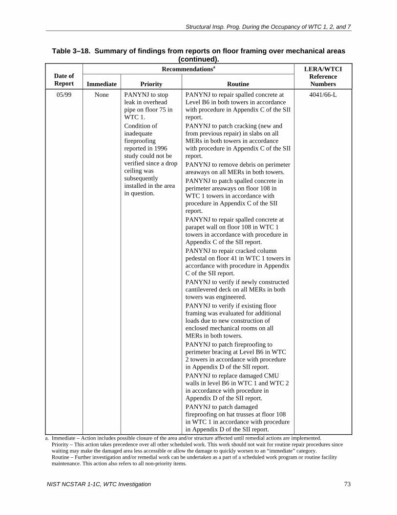
Structural Insp. Prog. During the Occupancy of WTC 1, 2, and 7
NIST NCSTAR 1-1C, WTC Investigation 73
Table 3–18. Summary of findings from reports on floor framing over mechanical areas (continued).
Recommendationsa Date of Report Immediate Priority Routine
LERA/WTCI Reference Numbers
05/99 None PANYNJ to stop leak in overhead pipe on floor 75 in WTC 1. Condition of inadequate fireproofing reported in 1996 study could not be verified since a drop ceiling was subsequently installed in the area in question.
PANYNJ to repair spalled concrete at Level B6 in both towers in accordance with procedure in Appendix C of the SII report. PANYNJ to patch cracking (new and from previous repair) in slabs on all MERs in both towers in accordance with procedure in Appendix C of the SII report. PANYNJ to remove debris on perimeter areaways on all MERs in both towers. PANYNJ to patch spalled concrete in perimeter areaways on floor 108 in WTC 1 towers in accordance with procedure in Appendix C of the SII report. PANYNJ to repair spalled concrete at parapet wall on floor 108 in WTC 1 towers in accordance with procedure in Appendix C of the SII report. PANYNJ to repair cracked column pedestal on floor 41 in WTC 1 towers in accordance with procedure in Appendix C of the SII report. PANYNJ to verify if newly constructed cantilevered deck on all MERs in both towers was engineered. PANYNJ to verify if existing floor framing was evaluated for additional loads due to new construction of enclosed mechanical rooms on all MERs in both towers. PANYNJ to patch fireproofing to perimeter bracing at Level B6 in WTC 2 towers in accordance with procedure in Appendix D of the SII report. PANYNJ to replace damaged CMU walls in level B6 in WTC 1 and WTC 2 in accordance with procedure in Appendix D of the SII report. PANYNJ to patch damaged fireproofing on hat trusses at floor 108 in WTC 1 in accordance with procedure in Appendix D of the SII report.
4041/66-L
a. Immediate – Action includes possible closure of the area and/or structure affected until remedial actions are implemented. Priority – This action takes precedence over all other scheduled work. This work should not wait for routine repair procedures since
waiting may make the damaged area less accessible or allow the damage to quickly worsen to an “immediate” category. Routine – Further investigation and/or remedial work can be undertaken as a part of a scheduled work program or routine facility
maintenance. This action also refers to all non-priority items.

Chapter 3
74 NIST NCSTAR 1-1C, WTC Investigation
Natural Frequency Measurements
The purpose of the inspection program was to determine the natural frequencies of oscillation of WTC 1 due to wind excitation. Only WTC 1 was instrumented with accelerometers which were located at six locations on floor 108. The accelerometers measured the accelerations in both principal directions of the building with respect to time due to wind. Data were recorded on tape whenever the acceleration of floor 108 exceeded approximately 0.003g. A spectral analysis of the recorded accelerations was made; peaks on this spectrum corresponded to the natural frequencies of various modes of vibration of the towers. The computed natural frequencies were to be compared with corresponding values that had been determined in the past. A significant change in the tower’s dynamic behavior was considered to be a possible indication of diminishing structural integrity. According to the reports, characteristics that may be observed or inferred by review of the recorded acceleration data were:
• Integrity of the lateral-load-resisting system;
• Condition of the viscoelastic damping system;
• Condition of other sources of inherent structural damping; and
• Other changes that affect fundamental characteristics of the lateral-load-resisting system.
Three reports were prepared by LERA. Dates and references for the reports are contained in Table 3–20.
The 1993 and 1995 reports compare the then available measured first mode natural frequencies of WTC 1 to those determined by the structural engineer in 1966, which were 0.084 Hz in the north-south direction and 0.096 in the east-west direction (WSHJ 1966). A summary of the measured first mode natural frequencies from the 1995 report, which contained the most current data, is given in Table 3–21.

Structural Insp. Prog. During the Occupancy of WTC 1, 2, and 7
NIST NCSTAR 1-1C, WTC Investigation 75
Table 3–19. Summary of findings from reports on floor framing over tenant areas. Recommendationsa Date of
Report Immediate Priority Routine LERA/WTCI
Reference Numbers
11/03/92 None None PANYNJ to replace fireproofing on steel members and repair or replace damaged CMU walls on floors noted in report. PANYNJ to perform survey of core holes, especially in prohibited areas.
R2582/67-L
04/01/95 None None PANYNJ to replace fireproofing on steel members and repair or replace damaged CMU walls on floors noted in report. PANYNJ to perform survey of core holes, especially in prohibited areas. PANYNJ to patch spalled concrete at locations noted in report.
R2582/67-L
12/10/97 None None PANYNJ to replace fireproofing on steel members and repair or replace damaged CMU walls on floors noted in report. PANYNJ to perform survey of core holes, especially in prohibited areas. PANYNJ to patch spalled concrete with exposed reinforcement at locations noted in report. PANYNJ to fill cores/holes in slab at locations noted in report.
4012/66-L
11/29/99 None PANYNJ to restore fireproofing on truss at floor 89 of WTC 2. PANYNJ to repair spalled concrete on floor 89 of WTC 2 in accordance with repair procedures given in Appendix D of the SII report. PANYNJ to repair spalled concrete on floors 33 and 91 of WTC 1 in accordance with repair procedures given in Appendix D of the SII report. PANYNJ to fill in cores with damaged reinforcement on floor 91 of WTC 1.
None 4023/66-L
a. Immediate – Action includes possible closure of the area and/or structure affected until remedial actions are implemented. Priority – This action takes precedence over all other scheduled work. This work should not wait for routine repair procedures since
waiting may make the damaged area less accessible or allow the damage to quickly worsen to an “immediate” category. Routine – Further investigation and/or remedial work can be undertaken as a part of a scheduled work program or routine facility
maintenance. This action also refers to all non-priority items.

Chapter 3
76 NIST NCSTAR 1-1C, WTC Investigation
Table 3–20. Reports on natural frequency measurements. Date of Report LERA/WTCI Reference Numbers
02/01/93 4073/66-L 04/12/95 4056/66-L 07/11/00 4094/66-L
Table 3–21. Measured first mode natural frequencies for WTC 1. Measured Frequency (Hz)
Event Date Wind Speed (mph) and
Direction N–S E–W 10/11/78 11.5, E/SE 0.098 0.105 01/24/79 33.0, E/SE 0.089 0.093 03/21/80 41.0, E/SE 0.085 0.092 12/11/92 49.0 0.087 0.092 02/02/93 20.0, NW 0.085 0.095 03/13/93 32.0, NW 0.085 0.094 03/10/94 14.0, W 0.094 0.094 12/25/94 37.0, W 0.081 0.091
Both the 1993 and 1995 reports conclude that the measured and computed first mode frequencies compare well, especially for the greater wind speeds. The 1995 report also concluded that the February 1993 bombing had no permanent measurable effect on the dynamic response of WTC 1. Both reports recommended that WTC 2 be instrumented similarly to WTC 1.
The 2000 SII report pointed out that PANYNJ had not been able to analyze the data acquired from the instrumentation of WTC 1 since 1998 because the PANYNJ laboratory that contained playback and analytical equipment necessary to assess the recorded data was dismantled in the fall of 1998. The report recommended that the capability to assess and analyze the accelerometer data be re-established promptly. The report further recommended that WTC 1 be additionally instrumented at a mid-level floor, and that WTC 2 be instrumented at its top floor and at a mid-level floor. The final recommendation from the 2000 report was that the responsibility for data collection and processing be transferred to a university or a similar academic research institution. Note that the proposed inspection interval of one year (see Fig. 3–5) was not followed.
Natural Frequencies of Floors
The purpose of this inspection program was to determine the natural frequencies of the floor systems in WTC 1 and WTC 2 and to compare them with corresponding values that were determined in the past. A significant change in the vibration characteristics of the floor system was considered to be a possible indication of diminishing structural integrity. The proposed inspection schedule (see Fig. 3–5) included measurement of the natural frequencies of floors every year on an ongoing basis, the proposed inspection schedule was not followed.
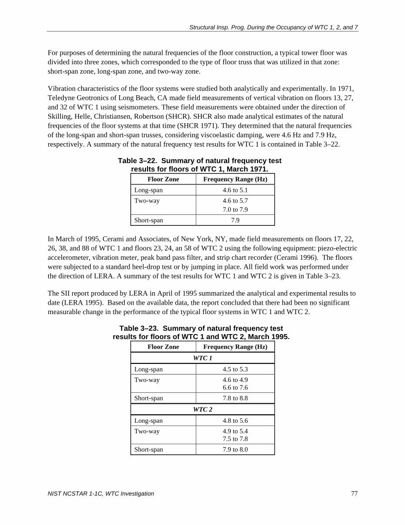
Structural Insp. Prog. During the Occupancy of WTC 1, 2, and 7
NIST NCSTAR 1-1C, WTC Investigation 77
For purposes of determining the natural frequencies of the floor construction, a typical tower floor was divided into three zones, which corresponded to the type of floor truss that was utilized in that zone: short-span zone, long-span zone, and two-way zone.
Vibration characteristics of the floor systems were studied both analytically and experimentally. In 1971, Teledyne Geotronics of Long Beach, CA made field measurements of vertical vibration on floors 13, 27, and 32 of WTC 1 using seismometers. These field measurements were obtained under the direction of Skilling, Helle, Christiansen, Robertson (SHCR). SHCR also made analytical estimates of the natural frequencies of the floor systems at that time (SHCR 1971). They determined that the natural frequencies of the long-span and short-span trusses, considering viscoelastic damping, were 4.6 Hz and 7.9 Hz, respectively. A summary of the natural frequency test results for WTC 1 is contained in Table 3–22.
Table 3–22. Summary of natural frequency test results for floors of WTC 1, March 1971.
Floor Zone Frequency Range (Hz) Long-span 4.6 to 5.1 Two-way 4.6 to 5.7
7.0 to 7.9 Short-span 7.9
In March of 1995, Cerami and Associates, of New York, NY, made field measurements on floors 17, 22, 26, 38, and 88 of WTC 1 and floors 23, 24, an 58 of WTC 2 using the following equipment: piezo-electric accelerometer, vibration meter, peak band pass filter, and strip chart recorder (Cerami 1996). The floors were subjected to a standard heel-drop test or by jumping in place. All field work was performed under the direction of LERA. A summary of the test results for WTC 1 and WTC 2 is given in Table 3–23.
The SII report produced by LERA in April of 1995 summarized the analytical and experimental results to date (LERA 1995). Based on the available data, the report concluded that there had been no significant measurable change in the performance of the typical floor systems in WTC 1 and WTC 2.
Table 3–23. Summary of natural frequency test results for floors of WTC 1 and WTC 2, March 1995.
Floor Zone Frequency Range (Hz)
WTC 1
Long-span 4.5 to 5.3 Two-way 4.6 to 4.9
6.6 to 7.6 Short-span 7.8 to 8.8
WTC 2
Long-span 4.8 to 5.6 Two-way 4.9 to 5.4
7.5 to 7.8 Short-span 7.9 to 8.0

Chapter 3
78 NIST NCSTAR 1-1C, WTC Investigation
Viscoelastic Damping Units
The report by LERA in May of 1996 provided a summary of the integrity of the viscoelastic damping units in WTC 1 and WTC 2 (LERA 1996). The integrity assessment represented a continuation of the on-going monitoring program for the damping units. A historical review related to the damping units is given in Appendix A of the SII report, which can be found in Appendix G of this report.
The report was based on information in the following studies:
• Laboratory testing of four in-service dampers taken from the towers (two per tower) performed by the Minnesota Mining and Manufacturing Company (Appendix A in LERA report)
• Analysis of measured dynamic response of WTC 1 to actual wind events conducted by the University of Western Ontario (Appendix B in LERA report)
• Investigation of Aging Effects – World Trade Center Dampers, Robert Fowler & Associates P.C., October 1, 1984 (Appendix C in LERA report).
Details of each study can be found in the applicable appendices cited above.
To assess the integrity of the damping units, the following characteristics were examined:
• Average loss tangent
• The mechanical behavior of the viscoelastic material used in the damping units was modeled by a linear viscoelastic law, where the stress-strain characteristics of the material are dependent on time and on the temperature of the material (WSHJ 1967b). When subjected to a uniform shear strain, which is a sinusoidal function of time, the stress-strain diagram of the viscoelastic material is elliptical. The area within the ellipse represents the work done per cycle of strain, which is dissipated as heat.
• The loss tangent, which is the ratio of the loss shear modulus of the viscoelastic material to the storage (elastic) shear modulus of the viscoelastic material, is directly proportional to the energy that can be dissipated per cycle of oscillation in the damping unit. Thus, to achieve maximum damping for a given material, the loss tangent should be made as great as possible. Over time, it was possible for the loss tangent to decrease.
• Average stiffness
• The stiffness of a damping unit was defined as the force it would take to produce a deformation of 0.020 in. in the viscoelastic material. The loss tangent is also directly proportional to the stiffness. Over time, it was possible for the stiffness to decrease.
• Mean damping ratios of WTC 1
• Damping of building sway motion in WTC 1 was achieved primarily from two sources: (1) intrinsic damping by the building structure and (2) damping from the viscoelastic

Structural Insp. Prog. During the Occupancy of WTC 1, 2, and 7
NIST NCSTAR 1-1C, WTC Investigation 79
damping units. In the design of the damping units, the intrinsic damping was assumed to be approximately 2 percent of critical damping.
• Contribution of damping units to total damping
• In the design, the contribution of the damping units to the total damping was assumed to be about 0.6 to 0.7 percent of critical damping.
• Mean natural frequency of oscillation of WTC 1
• A discussion on the natural frequency measurements of WTC 1 is give above.
The report concluded that based on the then available studies, the integrity of the damping units was good, and that no action was required at that time beyond the routine testing of the damping units.
Inspections Related to Explosion of February 16, 1993
The inspections listed in Table 3–24 were performed on WTC 1 after the terrorist bombing on February 16, 1993. The reports on each of these inspections can be found in WTCI-67-L.8
Table 3–24. Summary of inspections performed on WTC 1 after the terrorist bombing on February 16, 1993.
Date Company Inspection 05/14/93 LERA Level B2 and surrounding area. Bowed column 324
above Level B2; missing and bowed diagonals between Column 324 (Level B2) and Column 327 (Level B1); Crack at column 324 splice; bent spandrels and damaged floor beam connections.
Sept. 1993 U.S. Army Corps of Engineers Overall observation of damage due to explosion. 10/20/93 Wiss, Janney, Elstner Associates Investigation of plaza level cracks. 11/22/93 Proto Mfg. Ltd. Stress measurements of Level B2 columns. 12/08/93 Lucius Pitkin Inc. Examination of box column and diagonal beam repair. 10/10/94 LERA Memo on repair of concrete masonry unit wall.
A summary of the damage observations and a detailed discussion of the repairs made due to damage from the 1993 bombing is given in Chapter 4 of this report, which discusses the significant modifications and repairs that were made to WTC 1, 2, and 7.
After the repairs were completed on WTC 1, Lucius Pitkin, Inc. was requested to perform an ultrasonic thickness survey of box columns and an ultrasonic flaw detection survey of the diagonal and beam weld repairs that were made (Lucius Pitkin 1993). On level B1, thickness measurements were made on existing columns 345, 348, and 351 on a 2 in. grid pattern at areas along all four column faces and at various elevations as specified by LERA. Ultrasonic flaw detection surveys were performed on full penetration butt welds of newly erected diagonal bracing repairs at columns 321, 324, and 327 between
8 NIST WTC investigation catalog number.

Chapter 3
80 NIST NCSTAR 1-1C, WTC Investigation
levels B1 and B2 and on butt and fillet welds of beam repairs at columns 321 and 327 between levels B1 and B2. Ultrasonic flaw detection included scans of base metal on both sides of the weld for a distance of 1 ft for the full width of the plate. No indication of laminations was found on any of the new welds.
3.3 SUMMARY OF STRUCTURAL INSPECTION PROGRAMS
3.3.1 Inspection Programs
The PANYNJ commissioned various inspection programs during the occupancy of WTC 1, 2, and 7. The goal of these programs was to determine the condition of the structural systems in these buildings.
Facility Condition Survey Reports
Facility Condition Survey Programs were performed from 1990 through 2000 for WTC 1, 2, and 7. The following is a list of the structural elements that were inspected in WTC 1 and WTC 2:
• Exterior wall system (including columns, spandrel plates, and connections)
• Core columns (including column splices and lateral bracing below the 7th floor)
• Space frame (i.e., hat truss, including framing members and connections)
• Floor systems (including floor slabs and decks, trusses, rolled beams, bridging, and connections)
• Damping system (including damping units and connections)
The following is a list of the structural elements that were inspected in WTC 7:
• Foundation
• Framing (column splices, wind bracing systems, and interior beam connections)
• Floor slabs
• Con Edison Substation
A Due Diligence Physical Condition Survey was commissioned by the PANYNJ for WTC 1 and WTC 2 in 2000. On-site evaluations were performed during this survey to assess the general physical condition of the property, as it existed at that time.
Structural Integrity Inspection Programs
An inspection program to detect, record, and correct any signs of distress, deterioration, or deformation that could signal structural problems was implemented by PANYNJ in 1986 for WTC 1 and WTC 2. This program for structural integrity contained detailed guidelines on inspection, record-keeping, and follow-up procedures.

Structural Insp. Prog. During the Occupancy of WTC 1, 2, and 7
NIST NCSTAR 1-1C, WTC Investigation 81
The program included inspection or monitoring of the following items, among other things, in WTC 1 and WTC 2:
• TV mast (WTC 1 only)
• Roof water tightness and curtain wall
• Space usage
• Accessible columns, including exterior box columns at locations of spandrel intersections and “tree” junctions below floor 7 and above floor 1 (Plaza Level)
• Bracing at exterior column line below elevation 294 ft 0 in., and in WTC 2 only, the transfer trusses below floor 1 under exterior columns
• Hat truss between floor 107 and the roof
• Floor framing over mechanical spaces
• Concrete slabs, partitions, and finishes
• Steel framing, slabs, and the like where exposed for general repairs or tenant remodeling
• Measurement of natural frequency of tower and TV mast
• Floor natural frequency
• Damping units
• Plaster ceilings in main lobby
• Marble wall panel supports
• Review of maintenance reports
• Fire stairs
3.3.2 Findings from Inspection Programs
In general, the structural integrity inspections found that the structural systems of WTC 1, 2, and 7 were in good condition. The inspection consultants made numerous routine and some priority recommendations for repairs to the PANYNJ, as outlined in the above sections of this report. As noted above, it is evident that the PANYNJ did not complete action on some of these recommendations. Also, according to the PANYNJ, all of the construction records on repairs following the inspections were lost on September 11, 2001. Thus, it cannot be determined whether all of the recommended repairs were performed.

Chapter 3
82 NIST NCSTAR 1-1C, WTC Investigation
Table 3–25 gives a chronological summary of the locations where fireproofing was reported to be missing in WTC 1, 2, and 7, based on the findings from the applicable inspection programs.
Table 3–25. Summary of locations where fireproofing was found missing during structural inspections of WTC 1, 2, and 7.
Date Inspection Program Building(s) Location/Description
April 1990
Port Authority Facility Condition Survey Program – WTC 2
WTC 2 • Several small regions and a few large areas of fireproofing was found missing in elevator shafts 1–4, 8–13, 16, 18–21, 23, 24, 31, 35, 40, 42, 47, 52, and 58 (see Table B1 in the inspection report for floor levels that were inspected in these shafts).
• 8 in. wide by 1 ft-6 in. long area of fireproofing was found missing on top flange of beam between shafts 30 and 31 on floor 22.
• 100% of fireproofing was found missing on south face of Column 908 between floors 27 and 29 in Shaft 1.
• On floors 1–6, fireproofing was found missing on the floor framing at various locations.
• Hairline cracks were found in the concrete beam encasement (fireproofing) at scattered locations on all four mechanical equipment room levels.
October 1991
Port Authority Facility Condition Survey Program – WTC 1
WTC 1 • Missing fireproofing was found at various locations on the exterior wall columns and spandrel plates (exact locations were not given in the report).
• Several small areas and a few large areas of fireproofing was found missing from steel beams and columns in elevator shafts 2, 11, 12, 15, 26, 35, 43, 52, 62, 67, 77, 80, and 90 (see Table B-1 in the inspection report for floor levels that were inspected in these shafts).
• Fireproofing was found missing on a connection between a core column and a floor beam on floor 30 (exact location was not given in the report).
• Small areas of fireproofing were found missing from the floor framing at scattered locations on floors 9 through 107 (exact locations were not given in the report).
• Fireproofing was found missing on many damping units on floors 9 through 107 (exact locations were not given in the report).
• On 43rd floor, fireproofing was found missing on an area of 25 ft by 60 ft on the underside of metal deck between column lines 351 to 359 and 411 to 428. Fireproofing was also found missing on the floor beams in this area.
• On the 77th floor, fireproofing was found missing on an approximately 100 sq ft area of metal deck.

Structural Insp. Prog. During the Occupancy of WTC 1, 2, and 7
NIST NCSTAR 1-1C, WTC Investigation 83
Table 3–25. Summary of locations where fireproofing was found missing during structural inspections of WTC 1, 2, and 7 (continued).
Date Inspection Program Building(s) Location/Description October 1991
SII Report on Bracing Below Elevation 294 ft 0 in.
WTC 1 and WTC 2
• Between columns 148 and 151 of WTC 2 at the underside of Level B1, CMU wall acting as fireproofing was removed to allow pipes to pass through.
• Between columns 154 and 157 of WTC 2 at Level B2, CMU wall acting as fireproofing was removed for a doorway opening.
• Between columns 133 and 136 of WTC 2 at the underside of Level B1, CMU wall acting as fireproofing was removed for a doorway opening.
• Between columns 154 and 157 of WTC 2 between LevelsB5 and B6, CMU wall acting as fireproofing was removed for a doorway opening.
• Some degree of damage was found on all of the spray-on fireproofing on the diagonal bracing members between Levels B4 and B5 in both WTC 1 and WTC 2.
• Fireproofing (CMU and spray-on) was found missing at the intersection of diagonal bracing members G120B, G121B, and column 139 on Level B6 in WTC 2.
• CMU fireproofing was found missing at the intersection of diagonal bracing member G119B and column 130 on Level B6 in WTC 2.
• Fireproofing (CMU and spray-on) was found missing at the intersection of diagonal bracing member G418B and column 421 on Level B5 in WTC 2.
• At the base of column 357 on Level B6 in WTC 1, CMU fireproofing was found missing.
• Damaged fireproofing due to flooding was found at the intersection of diagonal bracing member G320A and column 324 on Level B6 in WTC 1.
• Fireproofing was found missing on the transfer truss members located between column 242 and 248 on Level B1 in WTC 2.

Chapter 3
84 NIST NCSTAR 1-1C, WTC Investigation
Table 3–25. Summary of locations where fireproofing was found missing during structural inspections of WTC 1, 2, and 7 (continued).
Date Inspection Program Building(s) Location/Description October 1992
SII Report on Hat Trusses
WTC 1 and WTC 2
• Fireproofing that was removed during the Facility Condition Survey inspections performed in 1990 and 1991 was not repaired.
• Fireproofing was found missing on two columns of the elevator machine room on floor 110 of WTC 2.
• Considerable damage was found to gypsum wallboard acting as fireproofing between column lines 806 and 807 on floor 107 in WTC 2.
• Gypsum wallboard acting as fireproofing was found missing around columns 903 and 904 on floor 110 in WTC 2.
• Damaged gypsum wallboard acting as fireproofing was found around columns 707 and 708 on floor 108 in WTC 1.
• Fireproofing was found missing or damaged on the steel members: (a) between columns 804 and 905 on floor 108 in WTC 1; (b) between columns 701 and 801 on floor 108 in WTC 1; (c) between columns 707 and 708 on floor 110 in WTC 2; (d) between columns 903 and 904 on floor 110 in WTC 2; (e) between columns 702 and 703 on floor 108 in WTC 1; (f) between columns 802 and 803 on floor 109 in WTC 1; (g) between columns 704 and 804A on floor 110 of WTC 1; (h) between columns 807 and 908 on floor 108 of WTC 1; (i) between columns 608 and 708 on floor108 of WTC 1; (j) between columns 1004 and 1005 on floor 108 of WTC 1; (k) between columns 603 and 606 on floor 107 of WTC 2; (l) between columns 331 and 1004 on floor 110 of WTC 2; (m) between columns 605 and 705 on floor 108 of WTC 1; (n) between columns 802 and 803 on floor 109 of WTC 1; and, (o) between columns 704 and 804A on floor 110 of WTC 1.
• Extensive gypsum wallboard damage was found between columns 904 and 1004 on floor 110 in WTC 1. Other gypsum wallboard damage was found at scattered locations on floors 108-110 in WTC 1 and WTC 2.
November 1992
SII Report on Floor Framing Over Tenant/Mechanical Areas
WTC 1 and WTC 2
• Fireproofing was found missing on some steel members in WTC 2 (exact locations were not specified in the report).

Structural Insp. Prog. During the Occupancy of WTC 1, 2, and 7
NIST NCSTAR 1-1C, WTC Investigation 85
Table 3–25. Summary of locations where fireproofing was found missing during structural inspections of WTC 1, 2, and 7 (continued).
Date Inspection Program Building(s) Location/Description November 1992
SII Report on Floor Framing Over Tenant/Mechanical Areas
WTC 1 and WTC 2
• CMU fireproofing was found missing on Levels B2 and B4 of WTC 2 next to the central corridor.
• Fireproofing was found not be reapplied after asbestos removal on floors 9, 10, and 12 (see Appendix A of SII report for exact locations).
• Fireproofing was found missing on some beams in the core area on floors 15 and 48 in WTC 2. Fireproofing was also found missing on the undersides of metal deck and top chords of floor trusses (exact locations were not specified in the report).
January 1993
SII Report on Accessible Columns
WTC 1 and WTC 2
• Spalling and missing fireproofing was found on the steel members in the express elevator shafts in both towers (members and locations were not specified in the report).
• Large areas of fireproofing were found missing on the faces of columns 606 and 607 in WTC 1.
• Fireproofing was found missing at the splice location of column 701 in WTC 1.
• Isolated areas of spalled fireproofing were found on members in the local elevator shafts (members and locations were not specified in the report).
February 1995
SII Report on Hat Trusses
WTC 1 and WTC 2
• Fireproofing that was removed during the Facility Condition Survey inspections performed in 1990 and 1991 was not repaired.
• Damaged gypsum wallboard was found at column 704 on floor 109 in WTC 1.
• Damaged gypsum wallboard was found between columns 904 and 1004 on floor 110 of WTC 1.
• Fireproofing was found missing at the following connections: (a) column 904 on floor 108 of WTC 2; (b) between columns 804 and 904 on floor 108 of WTC 2; and (c) Between columns 604 and 704 on floor 108 of WTC 2.

Chapter 3
86 NIST NCSTAR 1-1C, WTC Investigation
Table 3–25. Summary of locations where fireproofing was found missing during structural inspections of WTC 1, 2, and 7 (continued).
Date Inspection Program Building(s) Location/Description February 1995 (continued)
SII Report on Hat Trusses
WTC 1 and WTC 2
• Fireproofing was found missing or damaged on the steel members: (a) between columns 503 and 504 on floor 109 in WTC 1; (b) between columns 702 and 703 on floor 109 in WTC 1; (c) between columns 705 and 706 on floor 110 in WTC 1; (d) between columns 707 and 709 on floor 108 in WTC 1; (e) between columns 702 and 703 on floor 108 in WTC 1; (f) between columns 801 and 802 on floor 108 in WTC 1; (g) between columns 802 and 803 on floor 109 in WTC 1; (h) between columns 803 and 805 on floor 110 in WTC 1; (i) between columns 701 and 801 on floor 108 of WTC 1; (j) between columns 329-1005, 332-1004, and 903-1003 on floor 110 in WTC 1; (k) between columns 804 and 904 on floor 108 in WTC 1; (l) between columns 504-604, and 704-804 on floor 109 in WTC 1; (m) between columns 704 and 804A on floor 110 in WTC 1; (n) between columns 604-704 and 604-705 on floor 109 in WTC 1; (o) between columns 805 and 905 on floor 109 in WTC 1; (p) between columns 608-708, 305-310, 234-238, and 149-508 on floor 108 in WTC 1; (q) between columns 504 and 506 on floor 109 in WTC 2; (r) between columns 603 and 606 on floor 107 in WTC 2; (s) between columns 706 and 707 on floors 108 and 110 in WTC 2; (t) between columns 802-803 and 805-806 on floor 108 in WTC 2; (u) between columns 1004 and 1005 on floor 110 in WTC 2; (v) between columns 1005 and 1006 on floor 108 in WTC 2; (w) between columns 331-1104, 804-904, and 904-1004 on floor 110 in WTC 2; and (x) between columns 903 and 904 on floor 110 of WTC 2.

Structural Insp. Prog. During the Occupancy of WTC 1, 2, and 7
NIST NCSTAR 1-1C, WTC Investigation 87
Table 3–25. Summary of locations where fireproofing was found missing during structural inspections of WTC 1, 2, and 7 (continued).
Date Inspection Program Building(s) Location/Description March 1995 SII Report on Bracing
Below Elevation 294 ft 0 in.
WTC 1 and WTC 2
• Fireproofing (CMU and spray-on) was found missing or damaged on the steel members in WTC 1: (a) between columns 101-103, 121-124, 131-136, 133-139, 148-151, 224-227, 236-239, 245-248, 248-251, 257-259, and 401-403 on Levels B5-B6; (b) between columns 121-124, 127-130, 148-151, 142-145, 139-142, 136-139, 145-151, 151-154, and 251-254 on Levels B2-B3; (c) between columns 254-257, 303-306, 306-309, and 445-448 on Levels B4-B5; (d) between columns 251-254, 348-351, 401-406, 406-409, and 434-454 on Levels B1-B2; and, (e) between columns 454-457 on Levels B3-B4.
• CMU fireproofing was found removed at column 409 between Levels B5 and B6 in WTC 1.
• CMU fireproofing was removed between columns 433 and 436 between Levels B4 and B6 in WTC 1.
• Fireproofing was found missing at column 421 between Levels B4 and B5 and at column 427 between Levels B5 and B6 in WTC 1.
• Fireproofing (CMU and spray-on) was found missing or damaged on the steel members in WTC 2: (a) between columns 115-118, 139-142, 142-145, 145-148, and 212-218 on Levels B5-B6; (b) between columns 218-221, 330-333, and 342-345 on Levels B4-B5; (c) between columns 227-230 on Levels B3-B4; (d) between columns 133-136, 218-221, 227-230, 436-439, and 439-442, and at column 101 on Levels B1-B2; (e) between columns 242-248 between level B1 and floor 1; (f) between columns 139-148 and 327-330 on Levels B2-B3; (g) between columns 412-415, 415-421, and 421-424 on Levels B4-B6; and, (h) between columns 321-324, 439-442, 448-451, and 451-454 on Levels B4-B5.
• CMU fireproofing was removed at column 252 between Level B1 and floor 1 in WTC 2.
• CMU fireproofing was removed between columns 418 and 421 and between columns 433 and 436 between Levels B3 and B4 in WTC 2.
• CMU fireproofing was removed between columns 454 and 457 between Levels B2 and B3 in WTC 2.
• CMU fireproofing was removed between columns 412 and 415 and between column 115 and 118 between Levels B1 and B2 in WTC 2.
• CMU fireproofing was removed between columns 154 and 157 between Levels B5 and B6 in WTC 2.
April 1995 SII Report on Framing Over Tenant Areas
WTC 1 and WTC 2
• Fireproofing was found not be reapplied after asbestos removal on floors 17 and 22.
• Fireproofing was found missing on floor members at multiple locations in WTC 1 and WTC 2.
• Large areas of fireproofing were found missing on the underside of the floor trusses on floor 38 in WTC 1.

Chapter 3
88 NIST NCSTAR 1-1C, WTC Investigation
Table 3–25. Summary of locations where fireproofing was found missing during structural inspections of WTC 1, 2, and 7 (continued).
Date Inspection Program Building(s) Location/Description April 1995 SII Report on
Accessible Columns WTC 1 and WTC 2
• Large areas of fireproofing were found missing in service elevators 49A, 49 B, 50A, and 50 B in both towers.
• Fireproofing was found missing or damaged on the following columns in WTC 1: (a) column 901 between floors 2-44; (b) column 907 at Level B2 and floors 9, 16-20, 28-31, 34, and 36-38; (c) column 906 at Level B2; (d) column 903 at floors 31, 33, 34, 38, and 39; (e) column 902 at Level B2 and floors 39, 41, and 43; (f) column 601 between floors 2-78; (g) column 605 between floors 3-5; (h) column 606 at floors 8, 11, 19, 25-30, and 43-45; (i) column 607 between floors 2-78; (j) column 608 between floors 2-78; (k) column 704 between Level B1 and floor 78; (l) column 603and 606 at Level B2; (m) column 704 at Levels B1-B3; and, (n) columns 802 and 905 at Level B3.
• Fireproofing was found missing or damaged on the following columns in WTC 2: (a) column 908 on floors 27-31 and 33-36; (b) column 907 at floor 21; (c) column 902 at floors 7, 20, 22, 25, 34-36, 39, and 40; (d) column 901 at floors 15 and 31; (e) column 601 at floors 25 and 35-37; (f) column 602 at floors 7, 10, 12, 14,15, 27, 42, 48, 63, 66, and 75; (g) column 603 at floors 3 and 25; (h) columns 605 and 606 at Level B2; (i) column 607 at floors 29, 30, 47, 57, 59, 64, and 74; (j) column 608 at floors 41, 45, and 80; (k) column 703 at Level B6 and at floors 5, 17, and 48; (l) column 704 at Level B6 and at floors 48 and 74; and, (m) column 903 at Level B2.
April 1996 SII Report on Framing Over Mechanical Areas
WTC 1 and WTC 2
• Fireproofing was found tearing away from the underside of the metal deck on F08 in WTC 2.
• Damaged fireproofing was found on a beam in the southwest corner of the core on floor 107 in WTC 1.
• Fireproofing was found missing or damaged at many locations on the floor members supporting floor 75 in WTC 1.
• A 3 ft by 3 ft hole was found in the gypsum wallboard in the core area on floor 41 in WTC 1.
• Damaged CMU fireproofing for the perimeter diagonal bracing at Level B6 was found at 5 locations in WTC 1 and 3 locations in WTC 2.
• Damaged CMU fireproofing was found on 2 columns in WTC 1 and WTC 2 columns in WTC 2 at Level B6.
• Fireproofing was found missing at 3 locations in the hat truss on floor 108 in WTC 2.

Structural Insp. Prog. During the Occupancy of WTC 1, 2, and 7
NIST NCSTAR 1-1C, WTC Investigation 89
Table 3–25. Summary of locations where fireproofing was found missing during structural inspections of WTC 1, 2, and 7 (continued).
Date Inspection Program Building(s) Location/Description May 1996 SII Report on
Accessible Columns WTC 1 and WTC 2
• Fireproofing was found missing at the column bases that were inspected in the elevator pits in both towers.
• Fireproofing was found missing or damaged on columns in the following elevator shafts of WTC 1: (a) Shaft 6A, floor 77, column 904; (b) Shaft 17A, floor 1, column 604; (c) Shaft 34A, floor 15, column 706; (d) Shaft 35A, floors 6-7, column 805; (e) Shafts 69A and 70A, throughout entire shaft, columns 802 and 702; (f) Shaft 88A, floor 91, column 802; and (g) Shaft 95A, floors 98-100, column 706.
• Fireproofing was found missing or damaged on columns in the following elevator shafts of WTC 2: (a) Shaft 18B, floor 3, column 605; (b) Shaft 19B, floors 2, 5, 46, 55, and 73, column 606; (c) Shaft 20B, floors 22, 47, 49, 57, and 64, column 606; (d) Shaft 21B, floor 21, column 607; (e) Shafts 34B and 35 B, throughout entire shafts, columns 706 and 805; (f) Shaft 34B, floor 23, column 702; (g) Shaft 43B, floor 6, column 702; (h) Shaft 62B, floor 57, column 805; (i) Shaft 70B, floors 69 and 72, column 702; (j) Shaft 88B, throughout entire shaft, column 802; and, (k) Shaft 96B, floor 101, column 706.
May 1996 (continued)
SII Report on Accessible Columns
WTC 1 and WTC 2
• Fireproofing was found missing or damaged on connecting steel beams to columns in the following elevator shafts of WTC 1: (a) Shaft 34A, floors 22-23, column 706; (b) Shaft 35A, floors 11 and 17, column 805; (c) Shafts 42A and 43A, throughout entire shaft, columns 702 and 802; (d) Shafts 61A and 62A, throughout entire shaft, columns 706 and 805; (e) Shafts 69A and 70A, throughout entire shaft, columns 702 and 802; (f) Shafts 78A and 79A, floor 76, column 707; (g) Shaft 89A, Levels B1-B3, column 702; and, (h) Shafts 96A and 97A, throughout entire shafts, columns 707 and 806.
• Fireproofing was found missing or damaged on connecting steel beams to columns in the following elevator shafts of WTC 2: (a) Shaft 7B, throughout entire shaft, column 903; (b) Shaft 18B, floors 3 and 13, column 605; (c) Shaft 19B, throughout entire shaft, column 606; (d) Shaft 20B, floors 12, 13, 55, 57, 62, 67, 70, 74, and 77, column 606; (e) Shaft 34B, floor 24, column 706; (f) Shaft 42B, floor 32, column 702; (g) Shaft 43B, throughout entire shaft, column 702; (h) Shafts 61B and 62B, throughout entire shafts, columns 706 and 805; (i) Shaft 88B, throughout entire shaft, column 802; (j) Shaft 89B, floors, 82, 91, 96 and up, (k) column 702; Shaft 89B, throughout entire shaft, column 802; and, (l) Shaft 96B, floor 77, column 706.

Chapter 3
90 NIST NCSTAR 1-1C, WTC Investigation
Table 3–25. Summary of locations where fireproofing was found missing during structural inspections of WTC 1, 2, and 7 (continued).
Date Inspection Program Building(s) Location/Description April 1997 Port Authority Facility
Condition Survey Program – WTC 7
WTC 7 • Fireproofing was found missing on steel framing at floors 1, 2, 5, 6, 8, 11, 19, 23, 24, 26, and 44. Largest areas of missing fireproofing were found on floor 5 above the Main Lobby and floor 2 above the Loading Dock area.
May 1997 SII Report on Accessible Columns
WTC 1 and WTC 2
• Fireproofing was found missing at the column bases that were inspected in the elevator pits in both towers.
• Fireproofing was found missing or damaged on columns in the following elevator shafts of WTC 1: (a) Shaft 10A, floors 3, 9, 10, 22, and 27, column 902; (b) Shaft 11A, floors 8 and 30-33, column 901; (c) Shaft 24A, floor 4, column 807; (d) Shaft 40A, floors 3 and 33, column 702; (e) Shaft 51A, floor 45, column 807; (f) Shaft 52A, floors 45 and 53, column 708; (g) Shaft 57A, floors 44, 45, and 61, column 806; (h) Shaft 58A, floors 60 and 61, column 707; (i) Shaft 84A, floors 82 and 91, column 702; (j) Shaft 90A, floors 79, 91, and 95, column 703; and (k) Shaft 91A, floor 100, column 803.
• Fireproofing was found missing or damaged on columns in the following elevator shafts of WTC 2: (a) Shaft 24B, floor 16, column 807; (b) Shaft 25B, floors 2, 11, and 14, column 708; (c) Shaft 30B, floor 23, column 806; (d) Shaft 31B, floors 2-4, 6, 15, 25, column 707; (e) Shaft 36B, floors 8 and 15, column 801; (f) Shaft 37B, floor 32, column 701; (g) Shaft 48B, floors 35-41, column 905; (h) Shaft 52B, floors 45 and 51, column 708; (i) Shaft 57B, floor 52, column 806; (j) Shaft 58B, floors 57 and 60, column 707; (k) Shaft 67B, floor 47, column 702; (l) Shaft 68B, floor 44, column 802; (m) Shaft 90B, floors 94, 96, 98, and 99, column 703; and, (n) Shaft 91B, floors 84, 96, and 98, column 803.
• Fireproofing was found missing or damaged on connecting steel beams to columns in the following elevator shafts of WTC 1: (a) Shaft 10A, floors 16 and 22, column 902; (b) Shaft 24A, floors 2, 3, and 9, columns 708 and 807; (c) Shaft 41A, floors 19-24, column 802; and, (d) Shaft 84A, floor 81, column 702.
• Fireproofing was found missing or damaged on connecting steel beams to columns in the following elevator shafts of WTC 2: (a) Shaft 24B, floors 2, 5, and 12, column 807; (b) Shaft 48B, throughout entire shaft, column 905; (c) Shaft 57B, floors 44 and 55, column 806; (d) Shaft 64B, floor 49, column 701; (e) Shaft 68B, floors 44, 47, and 56, column 802; (f) Shaft 88B, floors 82 and 84,column 802; and (g) Shaft 90B, floor 98, column 703.
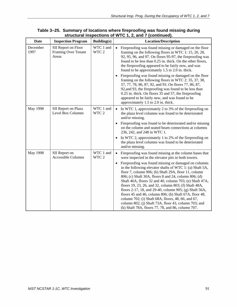
Structural Insp. Prog. During the Occupancy of WTC 1, 2, and 7
NIST NCSTAR 1-1C, WTC Investigation 91
Table 3–25. Summary of locations where fireproofing was found missing during structural inspections of WTC 1, 2, and 7 (continued).
Date Inspection Program Building(s) Location/Description December 1997
SII Report on Floor Framing Over Tenant Areas
WTC 1 and WTC 2
• Fireproofing was found missing or damaged on the floor framing on the following floors in WTC 1: 15, 20, 28, 92, 95, 96, and 97. On floors 95-97, the fireproofing was found to be less than 0.25 in. thick. On the other floors, the fireproofing appeared to be fairly new, and was found to be approximately 1.5 to 2.0 in. thick.
• Fireproofing was found missing or damaged on the floor framing on the following floors in WTC 2: 35, 37, 38, 57, 77, 78, 86, 87, 92, and 93. On floors 77, 86, 87, 92,and 93, the fireproofing was found to be less than 0.25 in. thick. On floors 35 and 57, the fireproofing appeared to be fairly new, and was found to be approximately 1.5 to 2.0 in. thick.
May 1998 SII Report on Plaza Level Box Columns
WTC 1 and WTC 2
• In WTC 1, approximately 2 to 3% of the fireproofing on the plaza level columns was found to be deteriorated and/or missing.
• Fireproofing was found to be deteriorated and/or missing on the column and seated beam connections at columns 236, 242, and 248 in WTC 1.
• In WTC 2, approximately 1 to 2% of the fireproofing on the plaza level columns was found to be deteriorated and/or missing.
May 1998 SII Report on Accessible Columns
WTC 1 and WTC 2
• Fireproofing was found missing at the column bases that were inspected in the elevator pits in both towers.
• Fireproofing was found missing or damaged on columns in the following elevator shafts of WTC 1: (a) Shaft 5A, floor 7, column 906; (b) Shaft 29A, floor 11, column 806; (c) Shaft 30A, floors 8 and 24, column 806; (d) Shaft 46A, floors 32 and 40, column 703; (e) Shaft 47A, floors 19, 23, 26, and 32, column 803; (f) Shaft 48A, floors 2-17, 18, and 29-40, column 905; (g) Shaft 56A, floors 45 and 46, column 806; (h) Shaft 67A, floor 48, column 702; (i) Shaft 68A, floors, 48, 66, and 67, column 802; (j) Shaft 73A, floor 43, column 703; and (k) Shaft 78A, floors 77, 78, and 86, column 707.

Chapter 3
92 NIST NCSTAR 1-1C, WTC Investigation
Table 3–25. Summary of locations where fireproofing was found missing during structural inspections of WTC 1, 2, and 7 (continued).
Date Inspection Program Building(s) Location/Description May 1998 (continued)
SII Report on Accessible Columns
WTC 1 and WTC 2
• Fireproofing was found missing or damaged on columns in the following elevator shafts of WTC 2: (a) Shaft 3B, floors 7 and 39, column 907; (b) Shaft 4B, floors 3, 5 and 23, column 906; (c) Shaft 8B, floor 14, column 903; (d) Shaft 9B, floors 10, 18, 23, and 34, column 902; (e) Shaft 16B, throughout entire shaft, column 603; (f) Shaft 17B, floors 28, 31, 38, 45, 52, 58, 59, 66, 69, and 73, column 604; (g) Shaft 28B, Level B1, column 707; (h) Shaft 40B, Level B1, column 702; (i) Shaft 41B, floor 2, column 802; (j) Shaft 46B, Level B1 and floors 2, 8, 13, 17, 20, and 35, column 705; (k) Shaft 47B, floors 4, 7, 17, 31, and 40, column 803; (l) Shaft 74B, floor 66, column 803; (m) Shaft 83B, floor 89, column 701; (n) Shaft 85B, floors 83, 89, and 93, column 802; and, (o) Shaft 94B, floors 77, 101, 104, and 106.
• Fireproofing was found missing or damaged on connecting steel beams to columns in the following elevator shafts of WTC 1: (a) Shaft 28A, throughout entire shaft, column 707; (b) Shaft 29A, floors 9 and 12, column 806; (c) Shaft 30A, floors 10 and 25, column 806; (d) Shaft 31A, throughout entire shaft, column 707; (e) Shaft 46A, throughout entire shaft, column 703; (f) Shaft 47A, floors 16, 17, 32, and 34, column 803; (g) Shaft 55A, floors 44-49 and 56, column 707; (h) Shaft 56A, floor 48, column 806; (i) Shaft 67A, throughout entire shaft, column 802; (j) Shaft 68A, floor 61, column 802; (k) Shaft 78A, floor 82, column 707; and (l) Shaft 79A, throughout entire shaft, column 806.
• Fireproofing was found missing or damaged on connecting steel beams to columns in the following elevator shafts of WTC 1: (a) Shaft 4B, floors 7, 15, 23, 31, 39, and 40, column 906; (b) Shaft 8B, floors 14, 20, and 45, column 903; (c) Shaft 9B, floor 34, column 902; (d) Shaft 16B, floors 2-48, column 603; (e) Shaft 17B, floors 28, 40, 48, and 69, column 604; (f) Shaft 40B, throughout entire shaft, column 702; (g) Shaft 46B, throughout entire shaft, column 703; (h) Shaft 47B, floors 6, 9, 13, 15, 27, 31, 33, and 34, column 803; (i) Shaft 82B, floors 86 and 87, column 801; (j) Shaft 83B, floor 86, column 701; (l) Shaft 84B, floor 94, column 702; (m) Shaft 85B, floors 78, 79, and 86-88, column 802; (n) Shaft 94B, floors 89 and 101, column 805; and (p) Shaft 95B, floors 81, 87, 94, and 101, column 706.

Structural Insp. Prog. During the Occupancy of WTC 1, 2, and 7
NIST NCSTAR 1-1C, WTC Investigation 93
Table 3–25. Summary of locations where fireproofing was found missing during structural inspections of WTC 1, 2, and 7 (continued).
Date Inspection Program Building(s) Location/Description May 1999 SII Report on Floor
Framing Over Mechanical Areas
WTC 1 and WTC 2
• Fireproofing was found missing on four perimeter braces in Level B6 of WTC 2. Most of other fireproofing on perimeter braces as reported in 1996 report was found to be repaired.
• A 3 ft by 3 ft hole was found in the gypsum wallboard in the core area on floor 41 in WTC 1.
• Damaged CMU fireproofing for the perimeter diagonal bracing at Level B6 was found at 5 locations in WTC 1 and 3 locations in WTC 2.
• Damaged CMU fireproofing was found on 2 columns in WTC 1 and WTC 2 columns in WTC 2 at Level B6.
• Fireproofing was found damaged on one of the hat truss members on floor 108 in WTC 1. Most missing fireproofing on hat truss members as reported in the 1996 was found to be repaired in WTC 2.
November 1999
SII Report on Floor Framing Over Tenant Areas
WTC 1 and WTC 2
• A 6 ft length of fireproofing was found to be missing on the bottom chord of one of the long-span floor trusses spanning from the core to the west wall on floor 89 in WTC 2 (see Appendix B of SII report for exact location of floor truss).
3.4 REFERENCES
Cerami and Associates, Inc. 1996. World Trade Center Tower I and II Floor System Natural Frequency Test. LERA Report No. 4076. March. (part of WTCI-66-L).
LERA (Leslie E. Robertson Associates). 1995. One and Two World Trade Center Floor Frequency Measurements. LERA Report No. 4055. April. (part of WTCI-66-L).
LERA (Leslie E. Robertson Associates). 1996. One and Two World Trade Center Damper Testing. May. (WTCI-230-L).
Lucius Pitkin, Inc. 1993. Examination of Box Columns and Diagonal Beam Repairs – World Trade Center, NY. Report No. ME-4525 S1. December. (part of WTCI-66-L).
Merritt & Harris, Inc. 2000. Report of Due Diligence Physical Condition Survey – World Trade Center. December. (WTCI-6-P).
PANYNJ (Port Authority of New York and New Jersey). 1986. Standards for Structural Integrity Inspection of the World Trade Center Towers A and B. Infrastructure Engineering Design Division, Engineering Department. March. (part of WTCI-66-L).
PANYNJ (Port Authority of New York and New Jersey). 1990. Port Authority Facility Condition Survey Program, World Trade Center Tower “B.” Engineering Quality Assurance Division, Engineering Department. (WTCI-120-P).

Chapter 3
94 NIST NCSTAR 1-1C, WTC Investigation
PANYNJ (Port Authority of New York and New Jersey). 1991. Port Authority Facility Condition Survey Program – World Trade Center Tower A Structure Elements. Engineering Quality Assurance Division, Engineering Department. October. (WTCI-118-P).
PANYNJ (Port Authority of New York and New Jersey). 1997. Port Authority Facility Condition Survey Program – 7 World Trade Center. Engineering Quality Assurance Division, Engineering Department. April. (WTCI-122-P).
SHCR (Skilling, Helle, Christiansen, Robertson). 1971. Vibration Characteristics of the Floors in the World Trade Center Towers. LERA Report No. 1012. September. (part of WTCI-66-L).
WSHJ (Worthington, Skilling, Helle, & Jackson). 1966. Part I, Final Chapter, WSHJ Wind Report. June. (part of WTCI-68-L).
WSHJ (Worthington, Skilling, Helle, & Jackson). 1967a. Structural drawings of WTC 1 and 2. (WTCI-50-L).
WSHJ (Worthington, Skilling, Helle, & Jackson). 1967b. The World Trade Center Report No. DU-1, Viscoelastic Damping Units. July. (part of WTCI-67-L).

NIST NCSTAR 1-1C, WTC Investigation 95
Chapter 4 SIGNIFICANT MODIFICATIONS AND REPAIRS TO THE STRUCTURAL
FRAMING SYSTEMS OF WTC 1, 2, AND 7
4.1 OVERVIEW
This chapter contains a summary of the significant modifications and repairs that were made to the structural framing systems of World Trade Center (WTC) 1, 2, and 7 from initial occupancy to September 11, 2001, including a discussion of the repairs that were made after the February 1993 bombing of WTC 1.
4.2 MODIFICATIONS AND REPAIRS MADE TO WTC 1
4.2.1 Openings Made in Floor Slabs
Structural modifications involving openings made in the floor slabs are listed in Table 4–1, along with a brief description of the work that was performed with respect to the modifications.
In all of the cases cited in Table 4–1, except for the 1995 case, documents included general notes and drawings that listed the codes, design criteria, and materials that were used in the design, and the proposed sequence of construction. Structural calculations on the design of new structural members and on the check of the capacities of existing structural members were included for the modifications made in 1995 and 1997. The documents for the 1999 modifications include comments made by the Tenant Construction Review Unit of the Port Authority of New York and New Jersey (PANYNJ or Port Authority) in regard to the project submittal. The Tenant Alteration Application Request Form, submitted to the Port Authority on behalf of the tenant, is also included.
Smaller floor penetrations, also made in the floor slabs, are not included in Table 4–1. In 1995, a number of openings were made in the floor slabs on levels 106 and 107 (Windows on the World Restaurant) to allow installation of equipment (W95-1114, PANYNJ, Newark).1 The maximum opening size was 5 ft 0 in. by 2 ft 6 in., and new beams were introduced to support the beams added around the openings. The structural engineer for this project was Leslie E. Robertson Associates (LERA). LERA was also the structural engineer for the chiller and condenser pipe penetrations on floors 94 through 100 that were made in 1998 for the tenant J&H Marsh & McLennan (W98-1197-02, PANYNJ, Newark). Openings ranged in size from 6 in. diameter core holes to 1 ft 6 in. by 6 in. slab openings.
4.2.2 Openings in Floor Slabs That Were Subsequently Closed
Openings in floor slabs that were subsequently closed are listed in Table 4–2. These openings were cut primarily for stairways.
1 The Port Authority document number is given in brackets; document was obtained from PANYNJ office in Newark, NJ.

Chapter 4
96 NIST NCSTAR 1-1C, WTC Investigation
General notes and drawings were provided for the 1985 and 1987 modifications listed in the table. These included the codes, design criteria, and materials that were used in the design, and the proposed sequence of construction. Design of the new structural members and checks of the capacities of existing structural members are contained in the documents for the modifications made in 1998.
Table 4−1. Openings made in floor slabs in WTC 1.
Date Floor(s) Tenant Structural Engineer Description of Modification Reference
1978 93–95 The Heyward-Robinson Co. Inc.
SHCR Slab openings were cut in floors 94 and 95 between columns 901, 902, 1001, and 1002 in core to accommodate new stair linking floors 93 through 95. Portions of existing beams on floors 94 and 95 were removed, and new beams were added to frame new openings. Support framing for 3 hour fire door was also provided.
LERA Box 8
1979 99–101 Deloitte Haskins & Sells
SHCR Slab openings were cut in floors 100 and 101 between columns 707, 708, 806, and 807 in core to accommodate new stair between these levels. Slab opening was also cut in floor 99 between columns 701, 702, 801, and 802 to accommodate new stair. Existing framing was removed and new structural members were added.
LERA Box 8
1985 89, 90 Swiss Bank International
Robertson Fowler & Associates
Slab opening was cut on floor 90 between columns 901, 902, 1001, and 1002 in core to accommodate new stair connecting floors 89 and 90. Existing framing was removed on floor 90 and new structural members were added on both floors.
LERA Box 8
1995 107 Windows on the World Restaurant
LERA Slab openings were cut in floor 107 for grease arrestors (exact location of openings could not be determined from drawings).
W95-1114 PANYNJ (Newark)
1997 105–Roof Unknown LERA Slab openings were cut for new elevator 99A near columns 704 and 804A in the core. Existing structural members were checked on floor 105 (support of pit beams), floor 110 (support of machine beams) and the penthouse roof (support of elevator) for the appropriate loads. It was determined that some of the beams on floor 105 and the roof were overstressed (not more than 4%) due to the increased loads. These members were not reinforced (calculations state that beams are O.K. since overstress < 5%).
WTCI-66-L
1999 93–100 J&H Marsh & McClennan
Gensler Several openings were cut in the floor slabs for stairs linking the different floors occupied by the tenant (exact location of openings could not be determined from drawings). Mention is also made to new framing supporting the Skyfold Partition.
W98-1197-03 PANYNJ (Newark)

Sig. Mod. & Repairs to the Struc. Framing Sys. of WTC 1, 2, & 7
NIST NCSTAR 1-1C, WTC Investigation 97
Table 4−2. Openings in floor slabs that were closed in WTC 1.
Date Floor(s) Tenant Structural Engineer Description of Modification Reference
1972 95 Fiduciary Trust Co.
SHCR New beams and floor deck were added to frame existing openings near column lines 124 and 239.
LERA Box 8
1985 95 Deloitte Haskins & Sells
Robertson Fowler & Associates
New beam and floor deck were added to frame existing opening between columns 901, 902, 1001, and 1002 in the core.
LERA Box 8
1987 91, 92 ADT LERA New beams and deck were added to frame existing stair opening in core near columns 603 and 702.
LERA Box 8
1998 96, 100 Unknown LERA New beams and deck were added to frame existing stair openings between columns 119 and 123 on floor 96 (outside of core) and near columns 707, 708, 806, and 807 on floor 100 (inside core)
W98-1192 PANYNJ (Newark)
4.2.3 Structural Members That Were Reinforced
Various floor members were reinforced to accommodate floor loads that were greater than the original design loads. A summary of reinforced members is contained in Table 4–3. In the introduction to documents submitted for the 1998 modifications, it is stated that the existing structural elements were checked using the PANYNJ Design Guidelines and Specifications. Calculations show that the Port Authority criteria were used for the existing loads on the floor system. The Tenant Alteration Application Review Request Form that was submitted to the Port Authority on behalf of the tenant was also included in the submittal package.
4.2.4 Repair Work Following the February 26, 1993 Explosion
Damage from the Explosion
The explosion of February 26, 1993 occurred on the second basement level (Level B2) near the center of the south wall of WTC 1 and adjacent to the Vista Hotel. Structural steel columns, diagonal braces, and spandrel beams in the immediate vicinity of the blast were damaged. Concrete floor slabs at Levels B1 and B2 in the parking garage and unreinforced masonry walls were also damaged over a large area. A discussion on the structural damage in WTC 1 caused by the blast is given below. A summary of the damage assessment in WTC 1 at Level B1 and Level B2 can be found in the floor plans in Figs. 4–1 and 4–2, respectively.
The explosion tore out the diagonal brace between Column 324 at Level B2 and Column 327 at Level B1 and severely bent the brace between Column 324 at Level B2 and Column 321 at Level B1 (see Figs. 4–1 and 4–2) (LERA 1993a). The braces on the south face of WTC 1 that were damaged by the blast are shown in Fig. 4–3.
Spandrel beams at Level B1 from Column 321 to 324 and from Column 324 to 327 were also damaged by the blast. Spandrels were bowed and cracked, and some had missing bolts (LERA 1993b).

Chapter 4
98 NIST NCSTAR 1-1C, WTC Investigation
Table 4−3. Structural members that were reinforced in WTC 1.
Date Floor(s) Tenant Structural Engineer Description of Modification Reference
1979 97–100 Deloitte Haskins & Sells
SHCR On floor 98, beams between columns 601 and 602 and between 701 and 702 were reinforced with bottom cover plates to support mechanical files that were hung from framing at this level. On floor 98, bridging trusses on the east side of the core between columns 218 and 221 were reinforced with new diagonals. No information is given on why the bridging trusses needed to be reinforced. On floor 99, 32 in. deep floor trusses along column lines 309, 311, 313, 315, 317, 319, 321, 323, 325, 327, and 329 were reinforced by welding additional rods and angles to the web members near the supports. Double angles were also welded to the bottom chords near midspan and to the top chords near the supports. No information was found on the reason why the trusses needed to be reinforced. On floor 99, core perimeter columns were reinforced with 3 new plates. No information was found on why the columns had to be reinforced. On floor 100, supports for a moveable wall were installed.
LERA Box 8
1996 86 WTC Planning
LERA Floor trusses were reinforced in the northwest corner of the building to accommodate new loads due to various types of filing systems.
LERA Box 9
1998 85 Ohrenstein & Brown
Gilsanz Murray Steficek
Steel beams and cover plates on existing beams were added to support load from new filing system. Also, existing floor trusses were reinforced by welding plates to the bottom chords.
WC98-1186 PANYNJ (Newark)
2001 47, 48 First Union Capital Management
LERA Floor trusses were reinforced to accommodate loads from new safes and filing cabinets.
W01-1115 PANYNJ (Newark)

NIS
T NC
STA
R 1-1C
, WTC
Investigation 99
S
ig. Mod. &
Repairs to the S
truc. Framing S
ys. of WTC
1, 2, & 7
Source: Reproduced with permission of The Port Authority of New York and New Jersey.
Figure 4–1. Damage assessment for WTC 1 at Level B1.

Chapter 4
100 N
IST N
CS
TAR
1-1C, W
TC Investigation
Source: Reproduced with permission of The Port Authority of New York and New Jersey.
Figure 4–2. Damage assessment for WTC 1 at Level B2.

Sig. Mod. & Repairs to the Struc. Framing Sys. of WTC 1, 2, & 7
NIST NCSTAR 1-1C, WTC Investigation 101
Source: Part of WTCI-167-STB. Reproduced with permission of The Port Authority of New York and New Jersey.
Figure 4−3. Bracing on south face of WTC 1 damaged by blast.
LERA observed a crack along the edge of the field splice in Column 324, located 3 ft above Level B2, that extended across most of the four faces of the column. Lucius Pitkin, Inc., a testing company that was hired to perform detailed examinations of the structural steel members and welds, confirmed the crack in Column 324. Ultrasonic testing was used to determine that the crack extended across the full width of the weld on the south face of the column and at each end of the weld on the north face. Magnetic-particle testing procedures were used to determine that the crack extended across the weld on the east face of the column and the majority of the weld on the west face as well. A small inward bow above Level B2 was also observed on the south face of this column. LERA noted that the braces and cracked column should be repaired, but they were not critical to the structural integrity of the building (LERA 1993a).
The explosion damaged the floor beams framing into the tower side of Column 324 (see Figs. 4–1 and 4–2) (Woodson 1993). The floor beam that framed into Column 324 at Level B1 sustained a

Chapter 4
102 NIST NCSTAR 1-1C, WTC Investigation
horizontal displacement of about 2.5 in., and the beam at Level B2 had a displacement of about 1 in. The bolted end connections of these beams also failed. Damage to floor beam connections also occurred at Columns 321 and 324 at Levels B3 and B4.
The concrete spandrel beam at Level B3 between Columns 318 and 330 sustained damage as a result of the blast. Similar damage occurred to the spandrel beam at Level B4 between the same columns.
The masonry walls in WTC 1 were also damaged by the explosion (Woodson 1993). The 6 in. thick walls on the south side of WTC 1 were breached over distances of approximately 50 ft to the east and 120 ft to the west of the blast origin. The 20 ft long masonry wall that formed part of the mechanical plenum that was located 10 ft inside of WTC 1 (near columns 321, 324, and 327) was completely destroyed. The masonry walls of the elevator shafts located approximately 60 ft inside of WTC 1 were also damaged. Other masonry walls inside of WTC 1 were damaged at distances of up to 90 ft from the blast origin. None of the damaged walls were load bearing, and none were supported at the top. The walls were built to 1 in. below the structure above; the joint was subsequently caulked. Many of the damaged walls deflected as though they were free at the top.
Repair Work
The diagonal bracing members between Levels B1 and B2 that were damaged by the explosion were removed and replaced with new members, which consisted of plates that were welded together (see Fig. 4–4). Also, new plates were added on the flanges of the diagonal between Column 312 at Level B2 and Column 315 at Level B1 (see Fig. 4–4).
New plates were added to the damaged spandrel beam at Level B1 between Columns 324 and 327 (see Fig. 4–4 and Fig. 4–5) and between Columns 321 and 324. Also, the cracked weld on the south face of the spandrel beam at Level B1 near Column 324 was removed and replaced (see Fig. 4–6).
LERA prescribed an eight-step procedure for repair to the crack in Column 324 immediately adjacent to the field weld at the column splice above Level B2 (LERA 1993a). No documentation was found to confirm that this crack was repaired according to that procedure.
The Level B1 floor beams framing into Columns 321, 324, and 327 that were damaged during the explosion were repaired by welding new short segments of W12×53 to the existing beams (see Fig. 4–7). New welded connections between the new beam segments and existing columns were provided.
Connections between floor beams and columns on Levels B3 and B4 were also repaired. As shown in Fig. 4–8, the damaged connection at Level B3 was removed, and a new beam seat and clip angle were installed at the connection between the W12×72 beam framing into Column 324. New web connection angles were installed for the beam framing into the same column at Level B4. At Level B3, repairs were made to the damaged bolts and to the gouge in the weld in the connection between the existing W12×72 floor beam and Column 321 (see Fig. 4–9).
Along the south face of WTC 1, the damaged concrete spandrel beams were demolished and replaced. Figures 4–10 and 4–11 show the details of the repair between Columns 318 and 330 at Levels B3 and B4, respectively. Similar repairs were made to the concrete spandrel between Columns 333 and 345 at Level B3.

Sig. Mod. & Repairs to the Struc. Framing Sys. of WTC 1, 2, & 7
NIST NCSTAR 1-1C, WTC Investigation 103
Columns 321, 324, and 327 were encased in 4 in. thick concrete masonry units (CMU) at the subgrade levels after the explosion, as depicted in Fig. 4–12. According to the drawings, existing spray-on fireproofing on spandrels and diagonals was to be repaired or patched after the columns were encased.
Source: Reproduced with permission of The Port Authority of New York and New Jersey.
Figure 4−4. Repair of damaged bracing in levels B1 and B2 of WTC 1.

Chapter 4
104 NIST NCSTAR 1-1C, WTC Investigation
Source: LERA 1993b. Reproduced with permission of The Port Authority of New York and New Jersey.
Figure 4−5. Repair of damaged spandrel beam in level B1 of WTC 1.
Source: Reproduced with permission of The Port Authority of New York and New Jersey.
Figure 4−6. Repair of cracked weld on spandrel beam in level B1 of WTC 1.

Sig. Mod. & Repairs to the Struc. Framing Sys. of WTC 1, 2, & 7
NIST NCSTAR 1-1C, WTC Investigation 105
Source: Reproduced with permission of The Port Authority of New York and New Jersey.
Figure 4−7. Repair of damaged floor beams at Level B1 in WTC 1.

Chapter 4
106 NIST NCSTAR 1-1C, WTC Investigation
Source: Part of WTCI-167-STB. Reproduced with permission of The Port Authority of New York and New Jersey.
Figure 4−8. Repair of damaged floor beam at Level B3 in WTC 1.

Sig. Mod. & Repairs to the Struc. Framing Sys. of WTC 1, 2, & 7
NIST NCSTAR 1-1C, WTC Investigation 107
Source: Part of WTCI-303-STB. Reproduced with permission of The Port Authority of New York and New Jersey.
Figure 4−9. Repair of damaged floor beam at Level B3 in WTC 1.

Chapter 4
108 NIST NCSTAR 1-1C, WTC Investigation
Source: Part of WTCI-303-STB. Reproduced with permission of The Port Authority of New York and New Jersey.
Figure 4−10. Repair of damaged reinforced concrete spandrel beam at Level B3 in WTC 1.

Sig. Mod. & Repairs to the Struc. Framing Sys. of WTC 1, 2, & 7
NIST NCSTAR 1-1C, WTC Investigation 109
Source: Part of WTCI-303-STB. Reproduced with permission of The Port Authority of New York and New Jersey.
Figure 4−11. Repair of damaged reinforced concrete spandrel beam at Level B4 in WTC 1.

Chapter 4
110 NIST NCSTAR 1-1C, WTC Investigation
Source: Part of WTCI-303-STB. Reproduced with permission of The Port Authority of New York and New Jersey.
Figure 4−12. Concrete masonry encasement of columns at subgrade levels in WTC 1.

Sig. Mod. & Repairs to the Struc. Framing Sys. of WTC 1, 2, & 7
NIST NCSTAR 1-1C, WTC Investigation 111
Damaged concrete encasement around existing steel beams was also repaired as required. Figure 4–13 shows a typical reconstruction detail for a beam located at Level B2. The extent of concrete encasement reconstruction at Levels B1 and B2 is shown in the drawings that were prepared by LERA (LERA 1993c).
Other repairs were made to spandrel beams at Level B5 and to the connection between the floor beam and Column 357 at the Concourse Level (see Figs. 4–14 and 4–15, respectively).
Lucius Pitkin, Inc. was hired to perform a thickness survey of box columns by the ultrasonic method and an ultrasonic flaw detection survey of diagonal and beam weld repairs made at WTC 1 (Lucius Pitkin 1993). Ultrasonic thickness measurements were made at Columns 345, 348, and 351 on Level B1. Ultrasonic flaw detection measurements were made on full penetration butt welds of new diagonal bracing repairs at Columns 321, 324, and 327 at Levels B1 and B2. Additional measurements were made on butt and fillet welds of beam repairs at Columns 321 and 327 between Levels B1 and B2. Results of the thickness survey are given in Table 1 and Fig. 1 of the Lucius Pitkin report (Lucius Pitkin 1993). Results of the ultrasonic flaw survey are given in Figs. 2 through 4 of the same report. No conclusions were made in the report on the adequacy of the test results.
Source: Part of WTCI-158-STB. Reproduced with permission of The Port Authority of New York and New Jersey.
Figure 4−13. Reconstruction details for existing encased steel beams in WTC 1.

Chapter 4
112 NIST NCSTAR 1-1C, WTC Investigation
Source: Part of WTCI-303-STB. Reproduced with permission of The Port Authority of New York and New Jersey.
Figure 4−14. Repair of encased steel spandrel beam at Level B5 in WTC 1.

Sig. Mod. & Repairs to the Struc. Framing Sys. of WTC 1, 2, & 7
NIST NCSTAR 1-1C, WTC Investigation 113
Source: Part of WTCI-303-STB. Reproduced with permission of The Port Authority of New York and New Jersey.
Figure 4−15. Repair of beam connection at Concourse Level in WTC 1.

Chapter 4
114 NIST NCSTAR 1-1C, WTC Investigation
4.2.5 Other Modifications
An FM transmitter station was installed on the 110th floor in 1997 for WNYC-FM (W96-1171, PANYNJ, Newark). The structural engineer for this project was J. C. Westrick & Associates. The documentation for this modification includes: (1) the Tenant Alteration Application Review Request Form submitted to the Port Authority on behalf of the tenant, (2) Port Authority comments made on the project submittal, (3) J. C. Westrick & Associates comments in response to Port Authority comments, and (4) a letter dated January 14, 1997 from the Supervisor of the Tenant Alteration Application Unit of the Port Authority to the Vice President of Operations and Engineering at WNYC-FM stating that review on the project was complete.
In June of 2000, structural calculations were submitted by LERA for the WABC Control Room on floor 110 (W00-1180, PANYNJ, Newark). A new transmitter and ductwork were suspended from the existing floor system at this level. The documentation for this modification includes: (1) the Tenant Alteration Application Review Request Form submitted to the Port Authority on behalf of the tenant, (2) Port Authority comments made on the project submittal, (3) LERA comments in response to Port Authority comments, and (4) a letter of approval from the Port Authority dated May 30, 2001.
Although no major modifications were made to the existing structural members because of the two projects cited above, they illustrate that the guidelines set forth by the Port Authority for alterations to the structural systems of the WTC buildings were followed (see Chapter 2 of this report for information on the Port Authority guidelines for inspection, repair, and modifications).
4.3 MODIFICATIONS AND REPAIRS MADE TO WTC 2
4.3.1 Openings Made in Floor Slabs
Structural modifications involving openings made in the floor slabs are listed in Table 4–4,which includes a brief description of the work that was performed with respect to the modifications.
In all of the cases cited in Table 4–4, except for the 1987 case, general notes and drawings in the documents listed the codes, design criteria, and materials that were used in the design and the proposed sequence of construction. Structural calculations were included for the modifications made in 1993, 1998, and 1999 (floors 25 and 26). The design of the new structural members and a check of the capacities of existing structural members were included in the calculations.
For the modifications performed in 1997, the documentation includes the Tenant Alterations Application Review Request Form and comments from the Port Authority in regard to the submittal. Similar documents are included in the submittal package for the modifications performed in 1998 and 1999 (work done on 88th and 89th floors).
Smaller floor penetrations, the largest of which was 17 in. in diameter, were made on floor 110 in 1979 for Sage Gray Todd & Sims (LERA Box 8). The structural engineer was LERA.

Sig. Mod. & Repairs to the Struc. Framing Sys. of WTC 1, 2, & 7
NIST NCSTAR 1-1C, WTC Investigation 115
4.3.2 Openings in Floor Slabs That Were Subsequently Closed
Openings in floor slabs that were subsequently closed are listed in Table 4–5. The design of the new structural members and a check of the adequacy of existing structural members were included in calculations in all cases.
Table 4−4. Openings made in floor slabs in WTC 2.
Date Floor(s) Tenant Structural Engineer Description of Modification Reference
1979 77 Ebasco Inc. SHCR Slab openings were cut at nine locations in the northeast quadrant of the building along the north and east faces of floor 77. Framing channels were also installed.
LERA Box 8
1987 96 Yamaichi International
LERA Slab opening was cut near columns 901 and 902 in the southeast quadrant near the core. New structural members were added.
LERA Box 10
1993 94-95 Fiduciary Trust
LERA Slab opening was cut between columns 507, 508, 607, and 608 in the core for stair linking floors 94 and 95. New structural members were added.
W93-2179 PANYNJ (Newark)
1997 99-101 AON Risk Services
Gensler Slab openings were cut for stairs linking floors 99, 100, and 101. No other information is provided.
WC97-2185-001 PANYNJ (Newark)
1998 99 AON Risk Services
The Office of James Ruderman
Slab opening was cut between columns 601, 602, 701, and 702 in the core on floor 99 for stairs leading down to floor 98. New structural members were added.
WC98-2212 PANYNJ (Newark)
1999 25, 26 Sun Microsystems
LERA Slab opening was cut near column 901 in the core for new stair between floors 25 and 26. New structural members were added.
WTCI-69-L, SA0279, 0006
1999 88, 89 Keefe, Bruyette & Woods, Inc.
Cetra/Ruddy Inc.
Slab opening was cut for stairs linking floors 88 and 89. No other information is provided.
WC99-2114 PANYNJ (Newark)
Table 4−5. Openings in floor slabs that were closed in WTC 2.
Date Floor(s) Tenant Structural Engineer Description of Modification Reference
1997 37, 38 Unknown LERA An escalator was removed between floors 37 and 38 near column 608. New floor deck and framing were added to close the opening.
WTCI-66-L
2000 95, 96 Fiduciary Trust
LERA New beams and deck were added to frame existing opening between columns 901, 902, 1001, and 1002 in the core on floor 96. Existing framing was checked for new loads.
WTCI-66-L

Chapter 4
116 NIST NCSTAR 1-1C, WTC Investigation
4.3.3 Structural Members That Were Reinforced
A summary of the structural members that were reinforced in WTC 2 is given in Table 4–6. The Tenant Alteration Application Review Request Form is included in the documentation for the modifications performed in 1999.
Table 4−6. Structural members that were reinforced in WTC 2.
Date Floor(s) Tenant Structural Engineer Description of Modification Reference
1993 96 Fiduciary Trust
LERA A number of long-span floor trusses and their connections in the northeast quadrant of the building were reinforced due to additional loads from high-density mobile filing cabinets.
W93-2179 PANYNJ (Newark)
1999 81 Fuji Bank Limited
LERA Documents reference adding reinforcement to existing two-way floor trusses to accommodate new UPS workspace. Documents do not specify the required amounts of reinforcement due to the new superimposed loads.
W99-2125 PANYNJ (Newark)
4.3.4 Other Modifications
In 1994, the slab in the elevator lobby on floor 90 (bounded by core columns 702, 703, 902, and 903) was repaired for Fiduciary Trust for some unknown reason (WTCI-66-L). LERA was the structural engineer for this repair, which consisted of demolishing and replacing a 5 in. lightweight aggregate concrete slab in this area.
4.4 MODIFICATIONS AND REPAIRS MADE TO WTC 7
A summary of the major modifications and repairs made to WTC 7 is given below. All modifications were to be made in accordance with the PANYNJ Tenant Construction Review Manual (see Chapter 2 of this report).
4.4.1 Modifications Made due to New Loading Requirements
Structural modifications due to new loading requirements are listed in Table 4–7. Included is a brief description of the work that was performed with respect to the modifications. In most cases, members were reinforced to accommodate floor loads that were greater than the loads for which these members were originally designed.
In all of the cases cited in Table 4–7, structural calculations were included on the check of the existing structural members and on the design of new structural members. The documents related to the 1988 modifications include comments made by the Tenant Construction Review Unit of the Port Authority in regard to the project submittal and responses from the structural engineer to the Port Authority on these comments. Similar documents are available for the modifications made in 1999 on the 40th floor, which

Sig. Mod. & Repairs to the Struc. Framing Sys. of WTC 1, 2, & 7
NIST NCSTAR 1-1C, WTC Investigation 117
include a copy of the Tenant Construction or Alteration Application that was submitted to the Port Authority on behalf of the tenant.
Table 4–7. Modifications made due to new loading requirements in WTC 7.
Date Floor(s) Tenant Structural Engineer Description of Modification Reference
1988 38 Salomon Brothers Inc.
Office of Irwin G. Cantor
Bottom and top cover plates were added to the existing W24x55 beams along column lines 37 and 40, and bottom cover plates were added to the existing W24x55 beams along column lines 30 and 35 to support new hanger loads.
W-7004 PANYNJ (Newark)
1989 24 General Auditing Office
Office of Irwin G. Cantor
Bottom cover plates were added to the existing W21x44 beam on column line 45 and the two adjacent W21x44 beams to the west of column line 45 to support additional load due to new file storage. The existing W36x135 girder framing between columns 76 and 79, which supported these beams, was also reinforced with a bottom cover plate.
W-8003 PANYNJ (Newark)
1989 47 Salomon Brothers Inc.
Office of Irwin G. Cantor
Bottom cover plates were added to the existing W16x31 beam along column line 2, the W16x26 beam along column line 3, and the W14x22 beams along column lines 4 and 5 to support additional mechanical equipment. The W33x130 girder on column line 56, which supported these beams, was reinforced with bottom and top cover plates.
W-7004 PANYNJ (Newark)
1990 11, 12 Spicer & Oppenheimer
Office of Irwin G. Cantor
Bottom cover plates were added to eight existing beams and girders in the northwest corner of the building on the 11th floor to support larger live loads. Similarly, bottom cover plates were added to three existing beams between column lines 48 and 49 and the girder between columns 70 and 73 on the 12th floor.
W-8005 PANYNJ (Newark)
1991 19 ITT Hartford Office of James Ruderman
Bottom cover plates were added to existing W24x55 and W24x76 beams to support new files and shelves. Exact location of these beams could not be determined from the documentation.
W-8010 PANYNJ (Newark)
1992 12 Securities Exchange Commission
Office of Irwin G. Cantor
Bottom cover plates were added to eleven existing beams in the northwest corner of the building to support legal files. A new W12x19 beam was also added between two of the existing beams.
W92-7056 PANYNJ (Newark)
1992 18, 19 Equal Employment Opportunity Commission
Office of Irwin G. Cantor
Bottom cover plates were added to existing W24 beams on the 18th floor on column lines 31, 32, and 33 to support larger live loads.
WTCI-166-P Disk 3 W92-7150

Chapter 4
118 NIST NCSTAR 1-1C, WTC Investigation
Table 4–7. Modifications made due to new loading requirements in WTC 7 (continued).
Date Floor(s) Tenant Structural Engineer Description of Modification Reference
1993 28 Salomon Brothers Inc.
Office of Irwin G. Cantor
Eight additional shear studs were added to an existing W16x26 beam located in the mechanical/electrical room to support new equipment loads.
W93-7138 PANYNJ (Newark)
1993 7, 8 American Express Bank
Office of James Ruderman
A new W12x14 beam located on the west side of the building between column lines 7 and 8 was added on the 8th floor to support a new CMU wall.
W93-7233 PANYNJ (Newark)
1994 7 through 29 Salomon Brothers Inc.
Office of Irwin G. Cantor
Bottom cover plates were added to twenty-two existing beams between columns 5 and 25 on the south side of the building on each floor between levels 7 and 29 to support larger live loads. Similarly, bottom cover plates were added to eight beams on the east side of the building between column lines 31 and 37 on each of these floors.
WTCI-166-P Disk 4 W93-7232
1995 20 ITT Hartford The Cantor Seinuk Group
Bottom cover plates were added to the existing W16x26 beams along column lines 23 and 25 to support new filing cabinets. Similarly, WT sections were welded to the bottom of the existing W16x26 beams that framed in between the above-mentioned beams. WT sections were welded to the bottom of the existing W16x26 beam east of column line 18 and the W16x26 beam on column line 19 to support new filing cabinets. Similarly, a bottom cover plate was added to the existing W16x26 beam east of column line 19.
W95-7153 WTCI-197-P
1999 37 Salomon Smith Barney
Gilsanz Murray Steficek
A new W16x40 beam was added between two existing W14x22 beams along column lines 76 and 77 to support a new high-density filing system.
W99-7134 PANYNJ (Newark)
1999 13 The Standard Chartered Bank
The Cantor Seinuk Group
Ten additional shear studs were added to an existing W4x55 beam to support additional loads from a new file room and a new UPS/LAN room. Exact location of this beam could not be determined from the documentation.
W99-7137-02 PANYNJ (Newark)
1999 40 Salomon Smith Barney
Gilsanz Murray Steficek
Four new W18x35 beams were added to support the new high-density files near column 76. WT4x20 sections were welded to the bottom of two existing W14x22 beams that supported the files. New W16x50 beams were connected below to the existing W36x135 girders that supported the beams in this area.
W99-7172 PANYNJ (Newark)

Sig. Mod. & Repairs to the Struc. Framing Sys. of WTC 1, 2, & 7
NIST NCSTAR 1-1C, WTC Investigation 119
Table 4–7. Modifications made due to new loading requirements in WTC 7 (continued).
Date Floor(s) Tenant Structural Engineer Description of Modification Reference
2000 31 Salomon Smith Barney
Gilsanz Murray Steficek
Top and bottom cover plates were added to an existing W27x94 beam between columns 77 and 80 to support a new high-density filing system. The existing beam connections were also reinforced with stiffened seat connections.
W00-7122 PANYNJ (Newark)
2000 38 Salomon Smith Barney
Gilsanz Murray Steficek
Bottom cover plates were added to existing W14x22 beams between columns 76 and 77 and between columns 77 and 78 to support a new high-density filing system. Also, the following existing girders were reinforced with bottom cover plates: (1) W36x135 between columns 76 and 79, (2) W27x94 between columns 77 and 80, and (3) W27x84 between columns 78 and 81.
W00-7224 PANYNJ (Newark)
2000 39 Salomon Smith Barney
Gilsanz Murray Steficek
New W14x53 beams were added under each rail of a new high-density filing system in lieu of reinforcing existing W14x22 beams between columns 76 and 77.
W00-7202 PANYNJ (Newark)
4.4.2 Openings Made in Floor Slabs
It is stated in PANYNJ (1997) that the 41st and 43rd floor slabs were completely removed on the east side of the building to accommodate the trading floors for Salomon Brothers Inc.
According to The Office of Irwin G. Cantor P.C. (1989), columns 76, 78, 79, 80, and 81 were reinforced with plates that ran from the top of the 39th floor to the underside of the 40th floor due to the removal of the floor slab at the 39th floor. Similarly, column 74 was reinforced with plates that ran from the top of the 43rd floor to the underside of the 44th floor due to the removal of the floor slab at the 43rd floor.
Structural modifications involving openings made in the floor slabs are listed in Table 4–8, including a brief description of the work that was performed with respect to the modifications.
Structural calculations on the design of new structural members and on the check of the existing structural members were included for the modification made in 1989 (3rd floor) and 1990.
4.4.3 Modifications Made to Beam Webs and Flanges
Modifications made to beam webs and flanges are summarized in Table 4–9 including a brief description of the work that was performed with respect to the modifications.

Chapter 4
120 NIST NCSTAR 1-1C, WTC Investigation
Table 4–8. Openings made in floor slabs of WTC 7.
Date Floor(s) Tenant Structural Engineer Description of Modification Reference
1989 3, 4 Salomon Brothers Inc.
Skidmore Owings & Merrill
On the 3rd floor, openings were cut on the west, north, and east sides of the building. New framing was introduced around these openings. On the 4th floor, new openings and framing were introduced on the north side of the building.
WTCI-166-P, Disk 2
1989 3 Salomon Brothers Inc.
The Office of Irwin G. Cantor
Two 2 ft-6 in. by 3 ft-6 in. openings were cut near columns 24 and 25. New C8x11.5 framing members were added around the openings.
W-7005 PANYNJ (Newark)
1990 11 Spicer & Oppenheimer
Office of Irwin G. Cantor
A new stair opening was made between columns 77, 78, 80, and 81. New W12x16 beams were added around the opening.
W-8005 PANYNJ (Newark)
1994 43 Salomon Brothers Inc.
Skidmore Owings & Merrill
A new slab opening was made near column 71 in the core area. New beams were added around the opening.
W94-7746, WTCI-166-P, Disk 4
4.4.4 Other Modifications
A list of structural modifications that were made to WTC 7 prior to April of 1997 is given in Chapter IV, Section A(5) of the Facility Condition Survey Report for WTC 7 (PANYNJ 1997). The following is a summary of the modifications that are noted in that report:
• In the Convention Area on the 3rd floor between column numbers 45 and 48A, steel plates have bee installed around the perimeter of the room between the slab and the floor surface (behind the wall coverings and above the suspended ceiling). According to the PANYNJ report, these plates were installed to protect attendees at the Convention Center from the magnetic field generated from the ConEd Substation beneath the conference rooms. No documentation was located that provides any additional details on this modification.
• On the north side of the 5th floor generator room, masonry block walls were added to partition the eight transformer vaults installed for Salomon Brothers. The vaults were between columns 46 and 53. No documentation was located that provides any additional details on this modification.
• A penthouse was constructed on the 47th floor roof to house the chiller plant and the cooling towers for Salomon Brothers. The chiller plant was an enclosed steel-framed structure with corrugated steel walls. It was approximately 25 ft in height and took up about one-third of the square footage of the 47th floor roof. The cooling towers were supported on a steel frame and were enclosed by louvered walls on the north and south sides and by the chiller plant and the bulkhouse on the east and west sides, respectively. No documentation was located that provides any additional details on this modification.

Sig. Mod. & Repairs to the Struc. Framing Sys. of WTC 1, 2, & 7
NIST NCSTAR 1-1C, WTC Investigation 121
The list of modifications in the PANYNJ report also included the removal of the floor slabs on floors 41 and 43 to accommodate the trading floors for Salomon Brothers, as noted in Sec. 4.4.2 of this report.
Table 4–9. Modifications made to beam webs and flanges in WTC 7.
Date Floor(s) Tenant Structural Engineer Description of Modification Reference
1993 28 Salomon Brothers Inc.
Office of Irwin G. Cantor
Two 1 in. by 36 in. openings, located 3 ft apart, were cut into the web of an existing W24x55 beam (unknown location). Plates were welded on each side of the web along the upper and lower edges of the openings.
W93-7138 PANYNJ (Newark)
1993 4-7, 16, 21, 29, 38, 45
Salomon Brothers Inc.
Office of Irwin G. Cantor
Notches were cut in the bottom flanges of various beams on these floors to accommodate ductwork. Plates were welded to the upper side of the bottom flanges.
W93-7221, WTCI-166-P, Disk 2
1998 1 Mayor’s Office of Emergency Management
The Cantor Seinuk Group
A notch was cut into the top flange of an existing beam (unknown location). Two plates, one on each side of the web, were welded under the top flange.
W98-1734, WTCI-166-P, Disk 5
1999 36-44 Salomon Smith Barney
The Cantor Seinuk Group
Two new openings (68 in. by 22 in. and 76 in. by 22 in.) spaced 3 ft-10 in. apart were cut into the web of the existing W24x62 beam framing into column 75. Horizontal and vertical stiffener plates were added on all sides of the openings. Also, a new WT15x74 section was welded to the bottom of the beam. The same size openings were made in an existing W27x94 beam on the 43rd floor, which was reinforced in a similar manner.
W99-7127 PANYNJ (Newark)
1999 42, 44 Salomon Smith Barney
Gensler New web openings were cut in numerous beams along the north and east sides of the building.
W99-7127, WTCI-166-P, Disk 6
4.5 REFERENCES
LERA (Leslie E. Robertson Associates). 1993a. The World Trade Center – The Explosion of 26 February 1993, Inspection Program, South Wall of Tower 1. May. (WTCI-69-L).
LERA (Leslie E. Robertson Associates). 1993b. “WTC Structural Integrity Investigation, Visual Inspection – Spandrel Damage Assessment.” July. (part of WTCI-160-STB).
LERA (Leslie E. Robertson Associates). 1993c. “Reconstruction of Tower A, El. 294-0 and 284-0,” structural drawing RE-TA-1.” December. (WTCI-456-STB).

Chapter 4
122 NIST NCSTAR 1-1C, WTC Investigation
Lucius Pitkin, Inc. 1993. Examination of Box Columns and Diagonal Beam Repairs – World Trade Center, New York, Report No. ME-4525 S1. December. (part of WTCI-67-L).
PANYNJ (Port Authority of New York and New Jersey). 1997. Port Authority Facility Condition Survey Program – 7 World Trade Center. Engineering Quality Assurance Division, Engineering Department. April. (WTCI-122-P).
The Office of Irwin G. Cantor P.C., “Salomon Brothers Inc. Base Building Modifications – 7 World Trade Center Structural Computations,” January 1989 (W-7004, Port Authority, Newark).
Woodson, S.C., Davis, J.L., and Walton, B.A., 1993. Observations of World Trade Center Damage, Technical Report SL-93, US Army Corps of Engineers Waterways Experiment Station. September. (part of WTCI-67-L).