MAIN AND INTERMEDIATE DISTRIBUTION FRAMES
28
AUSTRALIAN POST OFFICE INTERNAL PLANT INSTALLATION ENGINEERING INSTRUCTION Practice F 7010 Distribution CI; IA. Page 1. Issue 1, May, 1955. MAIN AND INTERMEDIATE DISTRIBUTION FRAMES This E.I. describes installation practices for Main and Intermediate Distribution Frames and includes:- The practices to be used in the assembly of the steel frame and its supports; A description of cabling practices and precautions to be taken; and Details of electrical and mechanical tests of fittings, the sequence of fitting, and the use of each item. INDEX. See Page No. GENERAL. 1. ASSEMBLY OF STEEL FRAMES. 2. PROVISION OF FITTINGS. 5. CABLING. 12. JUMPERING. 25. DESIGNATION. 25. EARTH SYSTEM ON AN M.D.F.. 26. __________ 1. GENERAL . 1.1 The Main Distribution Frame (M.D.F.) is a mild-steel structure on which is mounted equipment to provide facilities for the connection, protection and testing of line plant and exchange apparatus. The underground cables terminate on fuse mountings on the line side, and the ex- change cables terminate on protector strips on the equipment side of the frame. Terminal blocks, etc., are fitted in some instances where protection is not required on the exchange side of the frame. Circuits are cross-connected between these by means of jumper wires. 1.2 An Intermediate Distribution Frame (I.D.F.) is a mild-steel structure on which terminal blocks are mounted on both sides. These are known as Horizontal and Vertical blocks. The main purposes of the I.D.F. are:- (i) The incoming cables terminate on the vertical side and the cables outgoing to the next unit or rank of equipment are connected to the horizontal side. (ii) An I.D.F. may be provided between the M.D.F. and the equipment racks to interconnect the subscribers' line equipment with the final selector multiple or, in a C.B. manual exchange, the subscribers' multiple. (iii) An I.D.F. may also be used as a connecting field between two succeeding ranks of equipment. It replaces a Trunk Connecting Frame when the number of circuits exceeds the capacity of a T.C.F. 1.3 A Combined Distribution Frame when used in small exchanges combines the functions of the M.D.F. and I.D.F.
Transcript of MAIN AND INTERMEDIATE DISTRIBUTION FRAMES

AUSTRALIAN POST OFFICE INTERNAL PLANT INSTALLATION
ENGINEERING INSTRUCTION Practice
F 7010
Distribution CI; IA. Page 1. Issue 1, May, 1955.
M A I N A N D I N T E R M E D I A T E D I S T R I B U T I O N F R A M E S This E.I. describes installation practices for Main and Intermediate Distribution
Frames and includes:-
The practices to be used in the assembly of the steel frame and its supports;
A description of cabling practices and precautions to be taken; and
Details of electrical and mechanical tests of fittings, the sequence of fitting,
and the use of each item.
INDEX.
See Page No.
GENERAL. 1.
ASSEMBLY OF STEEL FRAMES. 2.
PROVISION OF FITTINGS. 5.
CABLING. 12.
JUMPERING. 25.
DESIGNATION. 25.
EARTH SYSTEM ON AN M.D.F.. 26.
__________
1. GENERAL.
1.1 The Main Distribution Frame (M.D.F.) is a mild-steel structure on which is mounted
equipment to provide facilities for the connection, protection and testing of line
plant and exchange apparatus.
The underground cables terminate on fuse mountings on the line side, and the ex-
change cables terminate on protector strips on the equipment side of the frame.
Terminal blocks, etc., are fitted in some instances where protection is not required
on the exchange side of the frame. Circuits are cross-connected between these by
means of jumper wires.
1.2 An Intermediate Distribution Frame (I.D.F.) is a mild-steel structure on which
terminal blocks are mounted on both sides. These are known as Horizontal and
Vertical blocks. The main purposes of the I.D.F. are:-
(i) The incoming cables terminate on the vertical side and the cables outgoing to
the next unit or rank of equipment are connected to the horizontal side.
(ii) An I.D.F. may be provided between the M.D.F. and the equipment racks to
interconnect the subscribers' line equipment with the final selector
multiple or, in a C.B. manual exchange, the subscribers' multiple.
(iii) An I.D.F. may also be used as a connecting field between two succeeding
ranks of equipment. It replaces a Trunk Connecting Frame when the number
of circuits exceeds the capacity of a T.C.F.
1.3 A Combined Distribution Frame when used in small exchanges combines the functions of
the M.D.F. and I.D.F.
INTERNAL PLANT INSTALLATION
Practice
F 7010
Issue 1, May, 1955. Page 2.
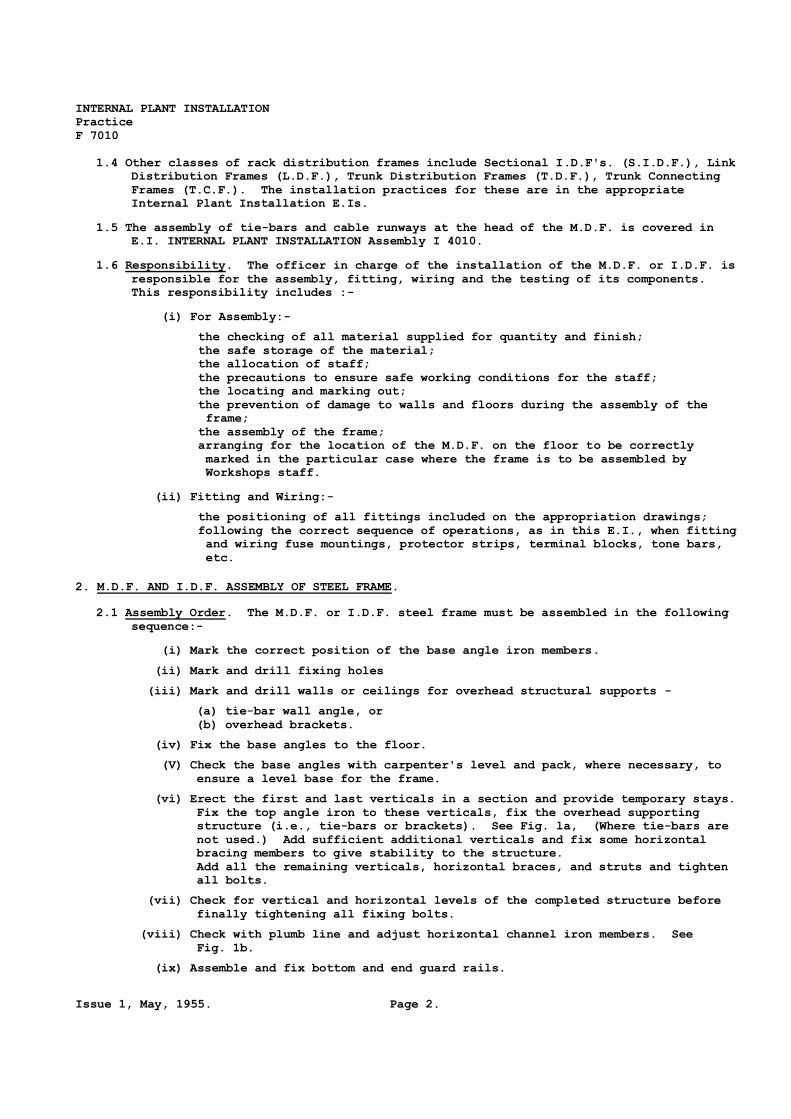
1.4 Other classes of rack distribution frames include Sectional I.D.F's. (S.I.D.F.), Link
Distribution Frames (L.D.F.), Trunk Distribution Frames (T.D.F.), Trunk Connecting
Frames (T.C.F.). The installation practices for these are in the appropriate
Internal Plant Installation E.Is.
1.5 The assembly of tie-bars and cable runways at the head of the M.D.F. is covered in
E.I. INTERNAL PLANT INSTALLATION Assembly I 4010.
1.6 Responsibility. The officer in charge of the installation of the M.D.F. or I.D.F. is
responsible for the assembly, fitting, wiring and the testing of its components.
This responsibility includes :-
(i) For Assembly:-
the checking of all material supplied for quantity and finish;
the safe storage of the material;
the allocation of staff;
the precautions to ensure safe working conditions for the staff;
the locating and marking out;
the prevention of damage to walls and floors during the assembly of the
frame;
the assembly of the frame;
arranging for the location of the M.D.F. on the floor to be correctly
marked in the particular case where the frame is to be assembled by
Workshops staff.
(ii) Fitting and Wiring:-
the positioning of all fittings included on the appropriation drawings;
following the correct sequence of operations, as in this E.I., when fitting
and wiring fuse mountings, protector strips, terminal blocks, tone bars,
etc.
2. M.D.F. AND I.D.F. ASSEMBLY OF STEEL FRAME.
2.1 Assembly Order. The M.D.F. or I.D.F. steel frame must be assembled in the following
sequence:-
(i) Mark the correct position of the base angle iron members.
(ii) Mark and drill fixing holes
(iii) Mark and drill walls or ceilings for overhead structural supports -
(a) tie-bar wall angle, or
(b) overhead brackets.
(iv) Fix the base angles to the floor.
(V) Check the base angles with carpenter's level and pack, where necessary, to
ensure a level base for the frame.
(vi) Erect the first and last verticals in a section and provide temporary stays.
Fix the top angle iron to these verticals, fix the overhead supporting
structure (i.e., tie-bars or brackets). See Fig. la, (Where tie-bars are
not used.) Add sufficient additional verticals and fix some horizontal
bracing members to give stability to the structure.
Add all the remaining verticals, horizontal braces, and struts and tighten
all bolts.
(vii) Check for vertical and horizontal levels of the completed structure before
finally tightening all fixing bolts.
(viii) Check with plumb line and adjust horizontal channel iron members. See
Fig. 1b.
(ix) Assemble and fix bottom and end guard rails.

AUSTRALIAN POST OFFICE INTERNAL PLANT INSTALLATION
ENGINEERING INSTRUCTION Practice
F 7010
Page 3. Issue 1, April, 1955.
For marking methods see E.I. INTERNAL PLANT INSTALLATION Practice M 6010.
(a) Overhead Supporting Bracket.
(b) Checking and Aligning Horizontal
Channel Iron Member.
FIG. 1. M.D.F. ASSEMBLY.
2.2 Assembly Aids.
(i) Jumper Ring No. 8 is used as a fixing bolt and must be positioned with its
free end against the vertical angle, as in Pig. 2a.
(ii) Jumper Ring No. 28 replaces the majority of the horizontal bracing members
of the Mo D.F. This jumper ring is shown in Fig. 2b.
(a) Jumper Ring No. 8.
(b) Jumper Ring No. 28.
FIG. 2. FITTING JUMPER RING.

INTERNAL PLANT INSTALLATION
Practice
F 7010
Issue 1, May, 1955. Page 4.
2.3 Mezzanine Platforms. When an M.D.F. has a mezzanine platform it must be in accord-
ance with the details included in the appropriate drawings supplied for the job.
The platform is supported By Bearer rods which are anchored to the ceiling. It is
stayed to the adjacent walls on the line side and by offset stays to the ceiling on
the equipment side.
Before starting the assembly of the platform, transfer the' floor plan outline to the
ceiling as in E.I. INTERNAL PLANT INSTALLATION Practice M 6010.
The pre-marking of the ceiling facilitates the assembly which must be done in the
following sequence:-
(i) Mark, drill and fix vertical Bearer rods.
(ii) Fix platform cross-member bearers.
(iii) Check and adjust these members so that the finished platform will Be level.
(iv) Fix stays to side wall and to ceiling.
(v) Place all checker plates or flooring in position.
(vi) Fix guard rails and steps.
(vii) Lay and fix rubber insulating floor covering.
2.4 Painting. When the steel frame assembly for the M.D. F. and the platform has been
finished, it must be painted with one coat of light Battleship grey, British
Standard specification 381, colour 831.
During this operation the following surfaces of the M.D.F. must be masked:-
(a) that end of the horizontal member to which the protector strip is fixed; see
Fig. 3a.
(b) the bracket to which the earthing bar is fixed. See Fig. 3b.
After the enamel on the remainder of the frame has dried, these unpainted surfaces
must be cleaned and given a coat of metallic aluminium paint.
FIG. 3. PARTS OF M.D.F. STRUCTURE TO BE MASKED WHEN PAINTING.
2.5 Cement Apron.
(i) cement apron below an M.D.F. or I.D.F. facilitates cleanliness and pre-
vents the splashing of solder on the floor covering and the collection of
rubbish in the area formed By the angle base members of the frame. An
apron must be provided for all island type M.D.F’s. and I.D.F’s. See
Figs. 4 and 5. However, when existing M.D.F’s. and I.D.F’s. which have
been finished as in sub-para (iii) are extended, the original method of
finishing must be used.
(ii) The cement apron must be fitted as in Fig. 4. The wood curb at the edges
must be fitted before filling-in with cement.
(iii) In earlier types of frames, the space between the base angles only was
filled with cement. See Fig. 5.
(iv) In each case the cement must be steel trowelled to a smooth finish and
painted and stippled to match the linoleum or other floor covering.
(v) Lead-covered cables passing through the apron must be protected from con-
tact with the cement. See Figs. 20a and 20b for approved methods.

AUSTRALIAN POST OFFICE INTERNAL PLANT INSTALLATION
ENGINEERING INSTRUCTION Practice
F 7010
Page 5. Issue 1, May, 1955.
FIG. 4. CEMENT APRONS UNDER M.D.F.
FIG. 5. CEMENT FILL BETWEEN
BASE ANGLES OF M.D.F.
3. M.D.F. AND I.D.F. - PROVISION OF FITTINGS.
3.1 This section describes the methods to be used in fixing jumper rings, protector
strips, fuse mountings, terminal blocks, etc., on Main and Intermediate Distribution
Frames.
3.2 Appropriation Drawing. The M.D.F. appropriation drawing for the job, detailing the
positions and types of the major items to be fitted, must be studied before work
starts.
3.3 Jumper Rings are provided on frames to facilitate the orderly running of jumper
wires. They provide for changing the direction of run of jumper wires and for
feeding them neatly into the various terminating strips. The standard types, their
applications and methods of fitting are in Table A and Figs. 2, 6 and 7.
Type
No. Applications Methods of Fitting
8 On M.D.F. to feed
jumpers from horizon-
tal plane on line
side to vertical
plane on equipment
side.
Threaded end passed
through M.D.F. vertical
angle iron and horizon-
tal brace. Acts as a
fixing bolt.
10 Grouping of Jumper
wires to serve a
particular fuse
mounting on M.D.F.
Threaded leg fixed with
nuts to horizontal
brace; other leg
located in hole in
brace to prevent
twisting.
27 On M.D.F., feeds
jumpers from horizon-
tal plane on line
side to vertical
plane on equipment
side.
Bolts onto M.D.F.
vertical.
28 On M.D.F. feeds
jumpers from horizon-
tal plane on line
side to vertical on
equipment side.
Bolt either side to
M.D.F. verticals,
Obviates use of
horizontal brace.
TABLE A. STANDARD TYPES OF JUMPER RINGS.

INTERNAL PLANT INSTALLATION
Practice
F 7010
Issue 1, May, 1955. Page 6.
FIG. 6. JUMPER RING NO. 10.
FIG. 7. JUMPER RING NO. 27.
3.4 Fuse Side of M.D.F. (Line side).
(i) Fuse mountings, terminal blocks, test jack strips and battery jacks are
located on the fuse side of the M.D.F. as directed on the appropriation
drawing; soldering iron holders are provided as required. The methods of
fitting these items and the sequence of operations are in Table B.
(ii) Before fuse mountings are fitted they must be examined as follows:-.
(a) Mechanical. Check that the springs have adequate tension and that
spring-fixing screws are not over-tightened.
(b) Insulation Resistance (with fuses fitted). Check that this is not
less than l,O00 megohms with a 500 volt megger.
(i) between the frame and all springs commoned, and
(ii) between each spring in turn and all other springs commoned.
(c) Type of Insulation. Ascertain if this is of moulded plastic, in which
case take special care when soldering - see Section 4, para 4.5.
Item Figure Sequence of fitting Remarks
Fuse
mountings
Fig. 8 After tails have been
positioned
Before fitting, check horizontal channel
supports for vertical alignment with the
aid of a plumb line.
Adjust with tool shown in Fig. 1.
Wiring is facilitated if the mountings
are fitted one vertical at a time.
Terminate this vertical before fitting
next vertical
Test jack
field
Fig. 9 After cables positioned
and fuse mountings
wired.
See Fig. 25 for method of shaping cable
form.
Battery
jacks
Fig. 10
and
Fig. 11
Fitted and wired before
soldering begins.
Wired to 50V A.C. if available direct to
transformers; or 50V DC via busbar fuse
system installed on adjacent rack.
Soldering
iron
holder
Fig. 12 Concurrently with
battery jacks.
Terminal
blocks
Fig. 13 After cables formed and
fanned out.
When terminating on horizontal side of
I.D.F.
TABLE B. FITTINGS ON FUSE SIDE OF M.D.F.
3.4 Exchange Side of M.D.F.
(i) Protector strips, terminal blocks (various), P.B.X. and Junction busying
strips, NU tone bars, test and special circuit jack boxes and battery

AUSTRALIAN POST OFFICE INTERNAL PLANT INSTALLATION
ENGINEERING INSTRUCTION Practice
F 7010
Page 7. Issue 1, April, 1955.
jacks are located as directed on the appropriation drawing. The methods of
fitting these and other items and the sequence of operations are detailed in
Table C.
(ii) Before protector strips are fitted they must be examined as follows:-
(a) Spring Tension. On new strips, check one spring assembly on each strip.
On damaged, recovered and reused strips, check each spring assembly.
Spring tensions must be:-
(i) Inner test spring to exert pressure of 1 lb. minimum, on heat coil,
with outer test spring held-off.
(ii) Outer test spring to exert pressure of 2 lb. minimum on inner test
spring at the point of contact.
(iii) With the heat coil fully operated or removed, the pressure at the
point of contact shall be 6 oz. minimum.
(iv) Outer and inner test springs combine to exert a minimum pressure of
3 lb. and a maximum pressure of 5 lb. on the heat coil.
Use Tool No. 67 for adjustments.
(b) Insulation Resistance. With arresters and heat coils fitted, use a 250 volt
megger to check that this is not less than 1000 megohms
(i) between the frame and all springs commoned, and
(ii) between each spring in turn and all other springs commoned.
(c) Type of Insulation. See if this is moulded plastic, in which case take
special care when soldering - refer Section 4, para 4.5.
Item Figure Sequence of Fitting Remarks
Protector Strip Fig. 3 After cables are formed
and fanned out.
Wiring is facilitated if the strips
are fitted one vertical at a time.
Terminate before fitting next vertical.
Terminal Blocks
Private wire
block on pro-
tectors.
Fig. 13
Fig. 14
After cables are formed
Fit concurrently with
protector strips.
(i) Power Distribution.
(ii) Ring Distribution.
(iii) Busy tone Distribution.
Used for 3rd wire termination.
P.B.X. and junc-
tion busying
strips.
Fig. 14 Before fitting fanning
strip to frame.
Fit to left-hand side of fanning
strip.
M.D.F.
Fanning
Strips for
Arrestors;
Fig. 14 After running but before
butting cables and
before fitting pro-
tector strips.
Aids in forming and fanning cables.
N.U. Tone Bar Fig. 14 After fitting fanning
strips but before
fitting protector
strips.
Fit to right-hand side of fanning
strips.
Jack boxes
(i) Test jacks
only.
(ii) Test and
special
circuit
jacks
Fig. 9 Fit holding brackets
when assembling steel
frame
or
Fit during assembly of
designation board.
Wire after major wiring operations on
frame are completed.
TABLE C. FITTINGS ON PROTECTOR SIDE OF M.D.F. (continued on next page).

INTERNAL PLANT INSTALLATION
Practice
F 7010
Issue 1, May, 1955. Page 8.
TABLE C. FITTINGS ON PROTECTOR SIDE OF M.D.F. (continued).
Item Figure Sequence of Fitting Remarks
Battery Jacks Fig. 10
& 11
Fitted and wired before
soldering begins.
Wired to %)V A.C. if available, direct
to transformers; or 50V D.C. via
busbar system.
Soldering iron
holder
Fig. 12 Concurrently with
battery jacks.
FITTINGS ON VERICAL SIDE OF I.D.F.
I.D.F
Terminal
Blocks
Fig. 13 After running cables
but before butting.
Aids in forming and fanning cables.
3.6 Maintenance Aids.
(i) A cabinet for spare fuses, arresters and heat coils and dummies may be fitted on
M.D.F's, or adjacent walls or columns. A typical cabinet is shown in Fig. 15.
(a) Fit a cabinet at each end of the frame when the number of verticals exceeds 30
(200/300 type M.D.F.).
(b) Fit additional cabinets as required on 300/400 type M.D.F's.
(ii) Storage of Test and Special Circuit Cords.
Cords are provided on an M.D.F. to connect circuits as required to the jack
boxes located at the top of the frame, and means must be provided to preserve a
neat and tidy appearance of these cords.
Typical arrangements for holding cords when in use are:-
(a) An open cage beneath the frame, shown in Fig. 16.
(b) Support rings above the frame, shown in Fig. 17.
(iii) Jumper Storage Reel.
This will be required adjacent to the fuse side of M.D.F's when the number of
verticals exceeds 20. A typical fitting is shown in Fig. 18. On M.D.F's of less
than 20 verticals jumper coils should be stored on pegs.
FIG. 8. FITTING FUSE MOUNTINGS TO HORIZONTAL CHANNEL IRON.

AUSTRALIAN POST OFFICE INTERNAL PLANT INSTALLATION
ENGINEERING INSTRUCTION Practice
F 7010
Page 9. Issue 1, April, 1955.
FIG. 9. FITTING BRACKETS FOR TEST JACK FIELD.
FIG. 13. MOUNTING TERMINAL BLOCKS.
FIG. 10. LINE SIDE.
FIG. 11. EQUIPMENT SIDE.
FITTING BRACKETS FOR BATTERY JACKS (Note Pilot Lamp).
FIG. 12. SOLDERING IRON HOLDER.

INTERNAL PLANT INSTALLATION
Practice
F 7010
Issue 1, May, 1955. Page 10.
FIG. 14. FITTING P.B.X. BUSYING STRIP, 3RD WIRE AND FANNING STRIPS AND PROTECTOR MOUNTING.
FIG. 15. M.D.F. CABINET FOR SPARE FUSES ETC. FIG. 16. OPEN TYPE CAGE FOR
HOLDING M.D.F. CORDS.

AUSTRALIAN POST OFFICE INTERNAL PLANT INSTALLATION
ENGINEERING INSTRUCTION Practice
F 7010
Page 11. Issue 1, April, 1955.
SUPPORT FOR M.D.F. CORDS
FIG. 17.
JUMPER STORAGE REEL.
FIG. 18.
INTERNAL PLANT INSTALLATION
Practice
F 7010
Issue 1, May, 1955. Page 12.
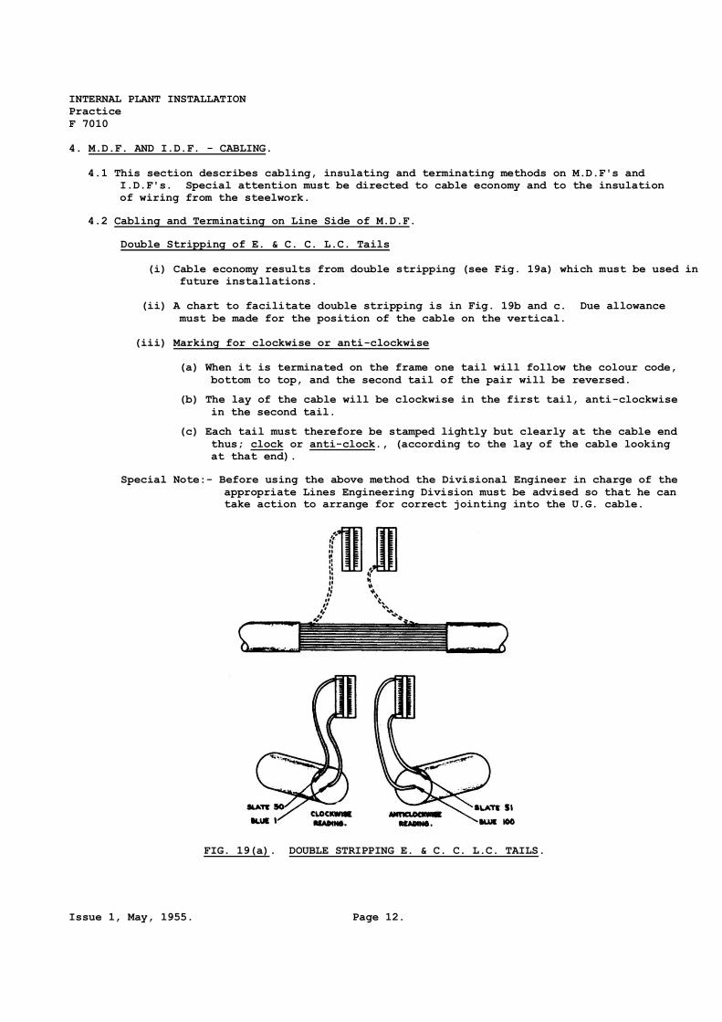
4. M.D.F. AND I.D.F. - CABLING.
4.1 This section describes cabling, insulating and terminating methods on M.D.F's and
I.D.F's. Special attention must be directed to cable economy and to the insulation
of wiring from the steelwork.
4.2 Cabling and Terminating on Line Side of M.D.F.
Double Stripping of E. & C. C. L.C. Tails
(i) Cable economy results from double stripping (see Fig. 19a) which must be used in
future installations.
(ii) A chart to facilitate double stripping is in Fig. 19b and c. Due allowance
must be made for the position of the cable on the vertical.
(iii) Marking for clockwise or anti-clockwise
(a) When it is terminated on the frame one tail will follow the colour code,
bottom to top, and the second tail of the pair will be reversed.
(b) The lay of the cable will be clockwise in the first tail, anti-clockwise
in the second tail.
(c) Each tail must therefore be stamped lightly but clearly at the cable end
thus; clock or anti-clock., (according to the lay of the cable looking
at that end).
Special Note:- Before using the above method the Divisional Engineer in charge of the
appropriate Lines Engineering Division must be advised so that he can
take action to arrange for correct jointing into the U.G. cable.
FIG. 19(a). DOUBLE STRIPPING E. & C. C. L.C. TAILS.

AUSTRALIAN POST OFFICE INTERNAL PLANT INSTALLATION
ENGINEERING INSTRUCTION Practice
F 7010
Page 13. Issue 1, April, 1955.
COMPLETED FORM FOR ONE UPRIGHT.
FIG. 19(b).

INTERNAL PLANT INSTALLATION
Practice
F 7010
Issue 1, May, 1955. Page 14.
FIG. 19(c). MAKING DOUBLE FORMS FROM ONE LENGTH OF CABLE.
4.3 The sequence of operations, methods to be used and precautions to be taken when cabling
the line side of an M.D.F. are in Table D.
The forming of LC tails on to Fuse Mountings can be facilitated by the use of the mild
steel Forming Jig illustrated in Fig. 26a, its use is especially applicable to areas of
high humidity. The tail should be laced to within 3" of the position from which the
wires fan to the fuse strip and sufficient lacing twine left to complete the lacing at
the end of the terminating. The jig (shown clearly as an insert in Fig. 26a) is position-
ed by removing the nut from the bolt nearest the fuse strip and then screwing the bolt
into the forming jig. After the wires have been formed and terminated, the jig is re-
moved and the spare lacing twine is then used to complete the form up to the changing
direction of the wires. This will result in neat forming and will assist in preventing
damage to the enamelled wire which may otherwise occur if a tight strain is placed on
the clove hitch at the end of the normal form.
The Jig (or forming device) can also be used to simplify forming from a butted and laced
form which approaches a terminal block at right angles.
Operation Figure Method Remarks
Feeding E. & C.C.
forms on to
M.D.F.
From below M.D.F.
(i) Using copper
tube
Fig. 20a Bell mouth both
ends of the tube
and sweat cables
to the lower end
of the copper
tube.
Avoid kinking the lead
tails. The earthing
wires, at the approp-
riate verticals, may
be fed through the
tubes at this stage.
(ii) Using wood
ferrule
Fig. 20b Wedge cables into
position and
screw shaped
wood-block to
top of ferrule.
Keep lead sheath away
from cement. Wood
ferrules should be
treated with wax
before placing in
position.
TABLE D. CABLING LINE SIDE OF M.D.F. (continued on next page).

AUSTRALIAN POST OFFICE INTERNAL PLANT INSTALLATION
ENGINEERING INSTRUCTION Practice
F 7010
Page 15. Issue 1, April, 1955.
Operation Figure Method Remarks
Feeding E. & C.C.
forms on to
M.D.F.
(continued)
In methods (i) and (ii) seal
hole with cotton waste and beeswax. A
Bitumastic compound must not be used
for this purpose as it will corrode the
lead sheath.
From Above M.D.F.
Using formed
channel.
Fig. 21 Take care to avoid
kinking cables when
placing in the
channels.
Insulating cable
form from MDF –
vertical run.
When fixed in to
angle iron
Fig. 22 Use (i) "Scotia"
timber
moulding.
(ii) Paper base
insulant.
(Prespan)
Before fitting (i) re-
cess flat surfaces to
take MDF fixing bolts.
Timber to be kiln dried
and treated with wax
or varnish before
fixing in position.
When fixed to
horizontal
channel support.
Fig 23 Insulate with
(i) paper base
insulant;
(ii) waxed tape
on support
Waxed tape shall not be
used on cable form
except at the sheath
butt.
Fixing cable and
cable form.
(i) to vertical
angle.
(ii) to horizontal
channel
support.
Fig. 26
Lace.
Lace or clip and
fitting tool –
refer to Fig. 26.
See para 4.3.
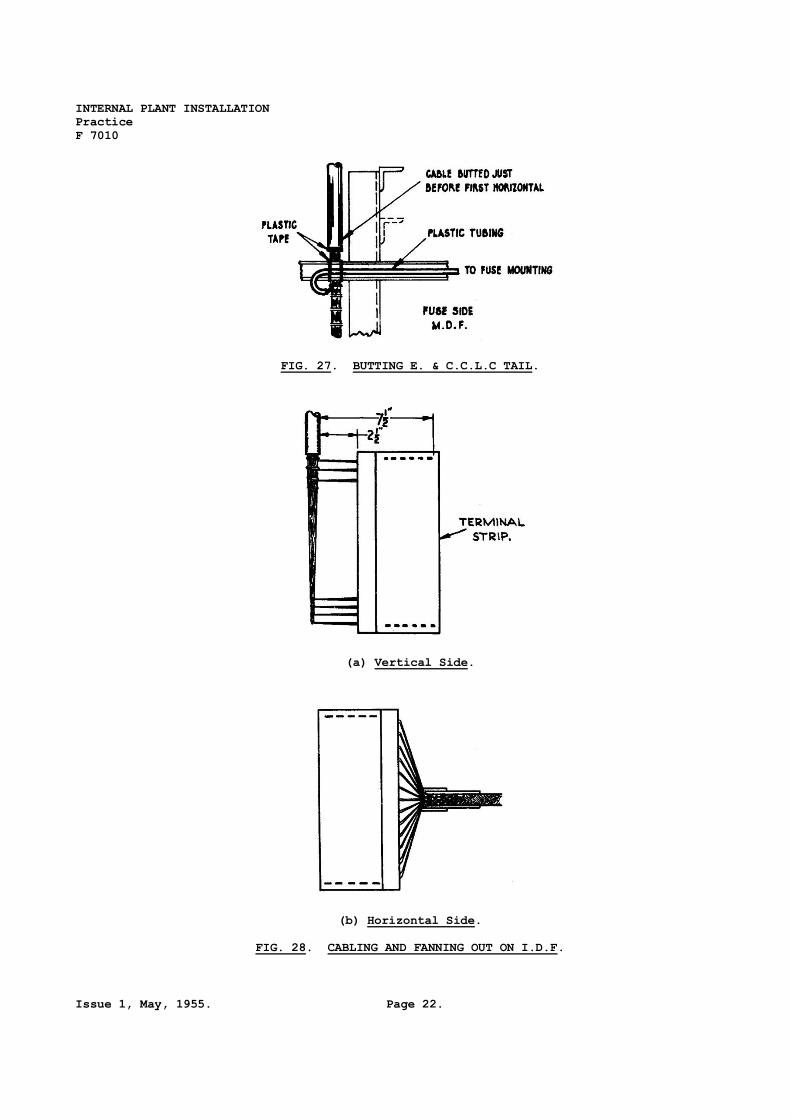
Butting Fig. 27 Immediately above or be-
low first feed-off
when feeding from top
or bottom of MDF re-
spectively.
Forms to fuse
mountings.
Fig. 27 Take out below
horizontal bracing
member of frame.
This obviates cutting
of form if cable sags.
Figs. 23
& 26
Fig. 27
Insulate from
steel work with –
(i) paper base
insulant;
(ii) clear plas-
tic tube.
Plastic tubing should
not be used in areas
of high humidity.
See para 4.3 also.
Tie or clip to
channel support.
T A B LE D . CA B L I N G L I N E S I D E O F M . D . F .

INTERNAL PLANT INSTALLATION
Practice
F 7010
Issue 1, May, 1955. Page 16.
4.4 Cabling and Terminating on Equipment side of M.D.F. The sequence of operations,
methods to be used and precautions to be taken are in Table E.
Operation Figure Method Remarks
Butting and fixing braided cables
On Terminal Blocks.
Fig. 28a Butt at next horizon-
tal support above the
first terminal to be
served by the cable.
Fix not less than
2½" behind T.B.
fanning strip.
Feed braided cables
on left-hand side
and well forward to-
wards protectors or
terminal blocks.
On fanning Strips Butt at horizontal
support above the
first terminal to
be served by
cables.
Fanning and terminating on pro-
tectors and P.W. terminal
blocks. etc.
Fanning to be done
before fixing pro-
tector strip or
Private Wire ter-
minal block.
(i) Protector strips )
)
)
)
(ii) P.B.X and Repeater )
Busying Strip )
)
)
(iii) Private wire )
terminal block )
Fig. 24
Spare wire. Loop
back through next
hole below in
fanning strip.
Stringers shall have
sufficient slack for
ease of termination.
Precaution when solder-
ing near moulded
plastic insulation –
refer para 4.5.
NU tone Distribution
Wired to miscellaneous
terminal block from
A.E.R Rack.
Jumper or wire from
miscellaneous ter-
minal block or
M.D.F. to NU Tone
Bars.
Forming and terminating on test
jack boxes.
Figs. 25,
29 & 30.
An "S" form must be
used to aid main-
tenance.
CA B LI N G E Q U I P M E N T S I D E O F M . D . F .
T A B LE E .

AUSTRALIAN POST OFFICE INTERNAL PLANT INSTALLATION
ENGINEERING INSTRUCTION Practice
F 7010
Page 17. Issue 1, April, 1955.
4.5 Soldering Precaution on Fuse Strips Fitted with Moulded Plastic Insulation. Plastic
insulation is moulded in a single sheet with separating ridges to isolate the spring
assemblies of these mountings; it is easily detected by examination. The officer in
charge of the installation must check to see if the fuse strips are fitted with
plastic moulded insulation and if so mast advise the staff of the following soldering
precautions:-
(i) Plastic insulation distorts at temperatures close to soldering temperature;
this distortion may cause the holding screws to slacken.
(ii) Apply the soldering bit to the tags for a minimum of time, and check the fix-
ing screws for tightness after soldering the strip.
4.6 Cabling and Termination on I.D.F's. The method to be used for positioning cables,
butting and fanning out the terminal blocks is shown for:-
(i) Vertical side - in Fig. 28a.
(ii) Horizontal side - in Fig. 28b.
(a) Using copper tube.
(b) Using wood ferrule.
FIG. 20. FEEDING E. & C.C. FORMS ONTO M.D.F. FROM BELOW M.D.F.
FIG. 21. FEEDING E. & C.C. FORMS ONTO M.D.F. FROM ABOVE M.D.F USING FORMED CHANNEL.

INTERNAL PLANT INSTALLATION
Practice
F 7010
Issue 1, May, 1955. Page 18.
INSULATING CABLE FORM FROM M.D.F. – VERTICAL RUN
IN ANGLE IRON. USING "SCOTIA” MOLDING.
FIG. 22.
INSULATING FORM ON HORIZONTAL CHANNEL IRON.
FIG. 23.

AUSTRALIAN POST OFFICE INTERNAL PLANT INSTALLATION
ENGINEERING INSTRUCTION Practice
F 7010
Page 19. Issue 1, April, 1955.
FANNING TO PROTECTOR STRIPS.
FIG. 24.
FORMING TO TEST JACK BOX.
FIG. 25.

INTERNAL PLANT INSTALLATION
Practice
F 7010
Issue 1, May, 1955. Page 20.
FIG. 26 FORMING, INSULATING, AND .

AUSTRALIAN POST OFFICE INTERNAL PLANT INSTALLATION
ENGINEERING INSTRUCTION Practice
F 7010
Page 21. Issue 1, April, 1955.
F IXING FORMS TO FUSE MOUNTINGS
INTERNAL PLANT INSTALLATION
Practice
F 7010
Issue 1, May, 1955. Page 22.
FIG. 27. BUTTING E. & C.C.L.C TAIL.
(a) Vertical Side.
(b) Horizontal Side.
FIG. 28. CABLING AND FANNING OUT ON I.D.F.

AUSTRALIAN POST OFFICE INTERNAL PLANT INSTALLATION
ENGINEERING INSTRUCTION Practice
F 7010
Page 23. Issue 1, April, 1955.
FORMS AND TERMINATING ON TEST JACK BOXES. LINE SIDE.
FIG. 29.

INTERNAL PLANT INSTALLATION
Practice
F 7010
Issue 1, May, 1955. Page 24.
FORMS AND TERMINATING ON TEST JACK BOXES. EQUIPMENT SIDE.
FIG. 30.

AUSTRALIAN POST OFFICE INTERNAL PLANT INSTALLATION
ENGINEERING INSTRUCTION Practice
F 7010
Page 25. Issue 1, April, 1955.
5. JUMPERING ON M.D.F’S and I.D.F’s.
5.1 Jumper wires to cross-connect circuits must be run in an orderly manner to avoid con-
gestion and to give a neat appearance. Adequate slack must be provided.
5.2 Broadcast lines must be cross-connected on M.D.F's with shielded jumper wire. These
are not fused and the jumper must be connected direct to the cable side of the fuse
mountings.
5.3 Junction Carrier Pairs must be specially labelled at fuse and arrester fitting.
5.4 The method of terminating in E.I. INTERNAL PLANT INSTALLATION Wires and Cables T 3010
must be used when terminating jumper wires.
6. M.D.F’S AND I.D.F’s DESIGNATIONS.
6.1 Designation Board on Protector Side of M.D.F. A designation board is required on
this side of an M.D.F. to indicate the functions of the verticals. It must be fitted
at the top of the frame after all cabling has been completed. See Fig. 31.
6.2 Designation Labels.
(i) Protector Side – fit label to Fig. 32b on each protector strip.
(ii) Line Side – fit label to Fig. 32a to top fuse mounting in each vertical.
6.3 Designations and Methods. Designations on the designation board, fuse mountings, pro-
tector strips, terminal blocks, test and special jack boxes, etc., shall adequately
describe the circuit function.
Abbreviations and methods to be used when designating are described in E.I.
TELEPHONE General Z 2002.
Signwriting for M.D.F. verticals must be on metal plates which can be clamped
between the vertical angle iron and the horizontal brace. See Fig. 33.
TYPES OF M.D.F. DESIGNATION BOARDS.
FIG. 31.

INTERNAL PLANT INSTALLATION
Practice
F 7010
Issue 1, May, 1955. Page 26.
(A) Line Side. (B) Protector Side.
FIG. 32. M.D.F. LABEL.
7. EARTH SYSTEM ON AN M.D.F.
7.1 The provision and wiring of the earthing system on an
M.D.F., its connection to the earthing bar on the
cable terminating frame, to the power discharge
panel and to the earth electrode system is described
in this Section.
7.2 Fitting Copper Earthing Bars. Copper earthing bars must
be fitted as follows:-
On the M.D.F.
FIG. 33. LABEL FOR M.D.F.
VERTICALS (INDICATES VERT.
NO. AND EQUIPMENT SIDE
CIRCUITS.
(i) When a Cable room is below M.D.F. Fit 1" × ¼" bar below protector
strips. Fig. 37.
(ii) When a U.G. cable frame is provided in Fit 1" × ¼" bar above
an equipment room. Protector strips.
On the Underground Cable Terminating Frame. Fit 2" × ¼" bar – refer Fig. 37.
The steel surfaces to which earthing bars are fixed must be scraped clean and
coated with metallic aluminium paint before fixing.
Joints in the earthing bar. The surfaces of the copper earth bar and fish plate
must be cleaned, the surfaces drawfiled, then smeared with vaseline, before bolting.
7.3 Earthing Protector Strips.
(1) Before fitting protector strips.
FIG. 34. TINNED COPPER EARTH
BONDING STRIP.
(a) the horizontal M.D.F. supporting members
must be Scraped clean and coated with
metallic aluminium paint;
(b) lacquer, if present, must be scraped
off the fixing surfaces;
(c) a tinned copper earth bonding strip
must be fitted between adjacent pro-
tector strips and the horizontal
channel supports. See Fig. 34.
FIG. 35. CONNECTION OF PROTECTOR
STRIPS TO EARTH BAR.

INTERNAL PLANT INSTALLATION
Practice
F 7010
Issue 1, May, 1955. Page 27.
(2) Gaps in Protector Field. Where a protector strip is not installed in the
vertical, the frames of adjacent protectors must be joined, with bare copper
wire (7/.036) (fitted with a lug and connected to the bonding strip at each
end.) Similar arrangement to Fig. 35.
(3) Connection of Protector Strips to Earthing Bar. The bottom strip in each
vertical must be connected to the earthing as in Fig. 35.
FIG. 36. FITTING EARTH BAR AND BONDING CABLE SHEATH TO IT.

INTERNAL PLANT INSTALLATION
Practice
F 7010
Issue 1, May, 1955. Page 28.
7.4 Connection between M.D.F. and Cable Terminating Frame Earthing Bars.
(i) When a cable well is below the M.D.F. a 7/.036 bar copper wire must be run
between the respective earthing bars at each tenth vertical (see Fig. 37).
(ii) When an Underground cable terminating frame is in the equipment room, the
earthing bar on this frame must be connected at one end by a bare 19/.064
copper cable to the M.D.F. earthing bar.
7.5 Connection of positive busbar of Power Discharge Panel to Earthing System.
(i) This connection must be run in bare copper cable generally in a conduit set
into the floor and connected at the M.D.F. to the earth bar.
(ii) It may be connected to whichever earthing bar (main Distributing frame or
Cable Terminating Frame) is the more convenient.
7.6 Connection of Earthing Bars to Earth Electrode System. Refer to E.I. INTERNAL PLANT
INSTALLATION General E 7010.
FIG. 37. CONNECTION BETWEEN M.D.F. AND C.T.F. EARTHING BARS WHERE
CABLE WELL IS BELOW M.D.F.
END.