MAHARASHTRA STATE BOARD OF TECHNICAL EDUCATION...
19
MAHARASHTRA STATE BOARD OF TECHNICAL EDUCATION (Autonomous) (ISO/IEC - 27001 - 2005 Certified) SUMMER – 14 EXAMINATION Subject Code: 17407 Model Answer Page No: 1/19 Important Instructions to examiners: 1) The answers should be examined by key words and not as word-to-word as given in the model answer scheme. 2) The model answer and the answer written by candidate may vary but the examiner may try to assess the understanding level of the candidate. 3) The language errors such as grammatical, spelling errors should not be given more. Importance (Not applicable for subject English and Communication Skills). 4) While assessing figures, examiner may give credit for principal components indicated in the figure. The figures drawn by candidate and model answer may vary. The examiner may give credit for any equivalent figure drawn. 5) Credits may be given step wise for numerical problems. In some cases, the assumed constant values may vary and there may be some difference in the candidate’s answers and model answer. 6) In case of some questions credit may be given by judgment on part of examiner of relevant answer based on candidate’s understanding. 7) For programming language papers, credit may be given to any other program based on equivalent concept. ```` 1. a) Attempt any SIX of the following 12 i) Enlist different types of ideal gas processes. 02 Answer: Following are the different types of ideal gas processes (Any four) 1. Isochoric (constant volume process) 2. Isobaric (constant pressure process) 3. Isothermal (constant temperature process) 4. Isentropic (constant entropy process) 5. Polytropic process. 02 ii) Define latent heat. 02 Answer: Latent heat: It is defined as the quantity of heat required for phase change of working substance at saturation temperature. 02 iii) Define capacity of compressor and free air delivery. 02 Answer: Capacity of compressor: It is the quantity of free air actually delivered by the compressor and expressed in m 3 /min and m 3 /s. Free air delivery: It is the actual volume of air delivered by the compressor when reduced to the intake temperature and pressure condition. 01 01
Transcript of MAHARASHTRA STATE BOARD OF TECHNICAL EDUCATION...
MAHARASHTRA STATE BOARD OF TECHNICAL EDUCATION (Autonomous)
(ISO/IEC - 27001 - 2005 Certified)
SUMMER – 14 EXAMINATION
Subject Code: 17407 Model Answer Page No: 1/19
Important Instructions to examiners: 1) The answers should be examined by key words and not as word-to-word as given in the model answer scheme.
2) The model answer and the answer written by candidate may vary but the examiner may try to assess the
understanding level of the candidate.
3) The language errors such as grammatical, spelling errors should not be given more. Importance (Not applicable
for subject English and Communication Skills).
4) While assessing figures, examiner may give credit for principal components indicated in the figure. The figures
drawn by candidate and model answer may vary. The examiner may give credit for any equivalent figure drawn.
5) Credits may be given step wise for numerical problems. In some cases, the assumed constant values may vary
and there may be some difference in the candidate’s answers and model answer.
6) In case of some questions credit may be given by judgment on part of examiner of relevant answer based on
candidate’s understanding.
7) For programming language papers, credit may be given to any other program based on equivalent concept.
````
1. a) Attempt any SIX of the following 12
i) Enlist different types of ideal gas processes. 02
Answer: Following are the different types of ideal gas processes (Any four)
1. Isochoric (constant volume process)
2. Isobaric (constant pressure process)
3. Isothermal (constant temperature process)
4. Isentropic (constant entropy process)
5. Polytropic process.
02
ii) Define latent heat. 02
Answer:
Latent heat: It is defined as the quantity of heat required for phase change of working substance at
saturation temperature.
02
iii) Define capacity of compressor and free air delivery. 02
Answer:
Capacity of compressor: It is the quantity of free air actually delivered by the compressor and
expressed in m3/min and m
3/s.
Free air delivery: It is the actual volume of air delivered by the compressor when reduced to the
intake temperature and pressure condition.
01
01

MAHARASHTRA STATE BOARD OF TECHNICAL EDUCATION (Autonomous)
(ISO/IEC - 27001 - 2005 Certified)
SUMMER – 14 EXAMINATION
Subject Code: 17407 Model Answer Page No: 2/19
iv) Enlist any two application of compressed air. 02
Answer: Application of compressed air: (Any two)
1. Operating tools in factories
2. Operating drills and hammers in road building
3. Starting diesel engines
4. Operating brakes on buses, trucks and trains
5. Spray painting
6. Excavating
7. To clean the large workshops
02
v) Give classification of gas turbine. 02
Answer: Classification of gas turbine: (Any two)
1. According to the path of the working substance:
i) Open cycle gas turbine
ii) Close cycle gas turbine
iii) Semi-closed cycle gas turbine
2. According to process of combustion:
i) Constant pressure gas turbine
ii) Constant volume gas turbine
3. According to direction of flow:
i) Radial flow
ii) Axial flow
iii) Tangential flow
4. According to principle of action of expanding gases: i) Impulse turbine
ii) Reaction turbine
5. According to their usage:
i) Constant speed
ii) ii) Variable speed
1 for each
02
vi) Enlist any four ‘non conventional’ type sources of energy. 02
Answer: Non conventional energy sources: (Any Four)
1) Wind energy
2) Solar Energy
3) Geothermal energy
4) Tidal Energy
5) Bio-Mass energy
02
vii) Define “calorific value” of fuel. 02
Answer:
“Calorific value” of fuel:
It is defined as the amount of heat liberated during complete combustion of 1 kg of fuel.
It is expressed in terms of KJ/kg.
02
MAHARASHTRA STATE BOARD OF TECHNICAL EDUCATION (Autonomous)
(ISO/IEC - 27001 - 2005 Certified)
SUMMER – 14 EXAMINATION
Subject Code: 17407 Model Answer Page No: 3/19
viii) Enlist any four types of gaseous fuels. 02
Answer: Types of gaseous fuels: (Any four)
1) Natural fuel
2) CNG
3) LPG
4) Water gas
5) Producer gas
6) Coal gas
7) Blast Furnace gas
8) Coke oven gas
9) Oil gas
02
b) Attempt any TWO of the following 08
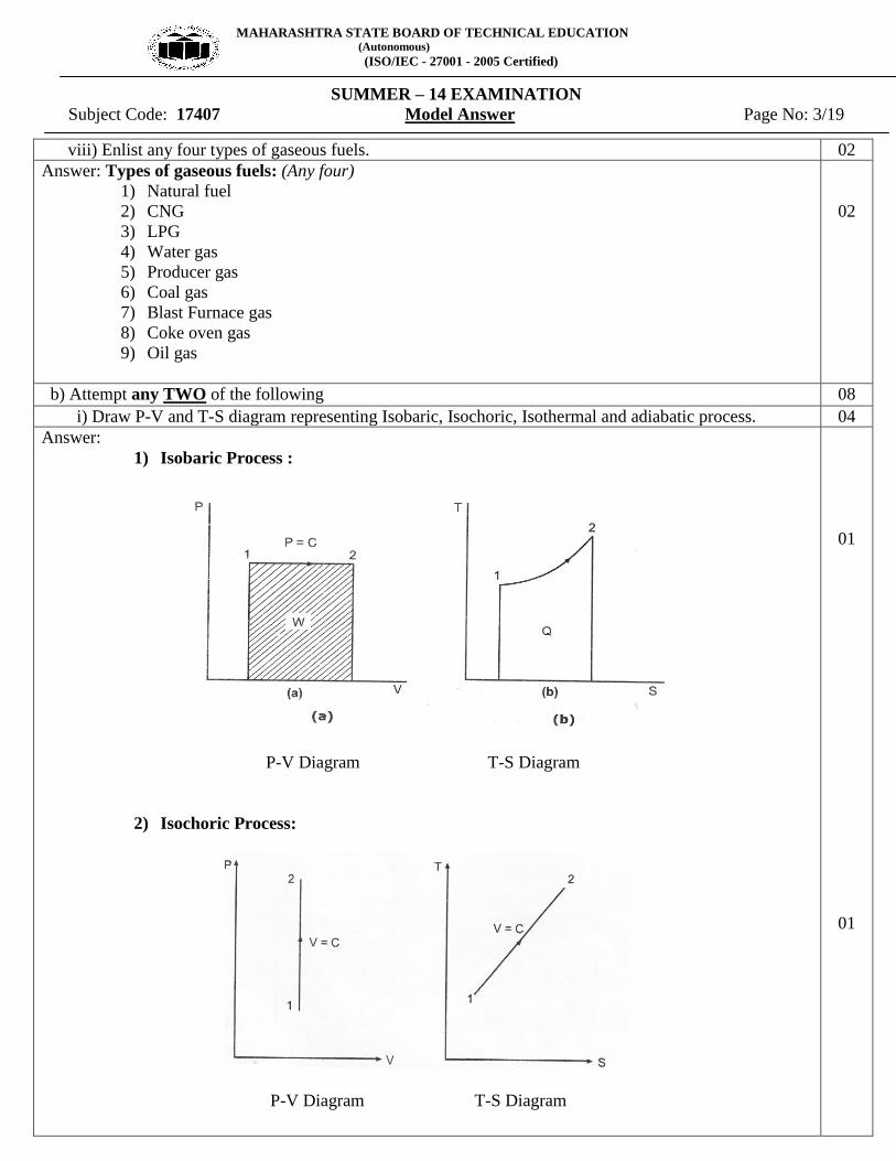
i) Draw P-V and T-S diagram representing Isobaric, Isochoric, Isothermal and adiabatic process. 04
Answer:
1) Isobaric Process :
P-V Diagram T-S Diagram
2) Isochoric Process:
P-V Diagram T-S Diagram
01
01

MAHARASHTRA STATE BOARD OF TECHNICAL EDUCATION (Autonomous)
(ISO/IEC - 27001 - 2005 Certified)
SUMMER – 14 EXAMINATION
Subject Code: 17407 Model Answer Page No: 4/19
3) Isothermal Process:
P-V Diagram T-S Diagram
4) Adiabatic Process:
P-V Diagram T-S Diagram
01
01
ii) Explain formation of superheated steam from water at 00 C at constant pressure.
Give enthalpy of following points:
1) point in wet region
2) point in dry saturated condition
3) Point in superheated condition.
04
Answer: Formation of superheated steam:
When water is heated from 00 C to saturation temperature, this rise in temperature sense with the
help of thermometer, hence it is called as sensible heat. During this heat addition, the liquid phase of water
will remains same.
When heat is added after saturation temperature the liquid phase of water is changing to vapour
phase. During this phase transformation the saturation temperature will remain same.
When heat is added after dry saturated temperature the saturated steam is converted into
superheated steam.
02
MAHARASHTRA STATE BOARD OF TECHNICAL EDUCATION (Autonomous)
(ISO/IEC - 27001 - 2005 Certified)
SUMMER – 14 EXAMINATION
Subject Code: 17407 Model Answer Page No: 5/19
Enthalpy:
1) point in wet region:-
hwet = hf + x.hfg
2) point in dry saturated condition:-
hg = hf + hfg
3) Point in superheated condition:-
hsup = hg + m Cp (Tsup- Tsat)
01
01
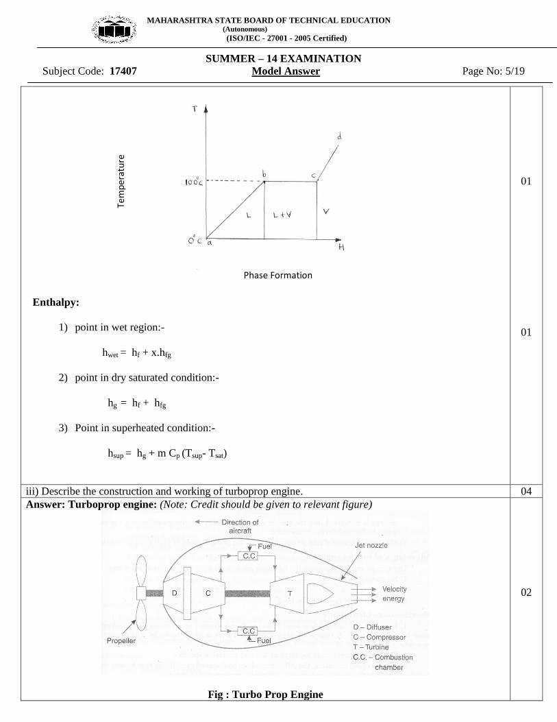
iii) Describe the construction and working of turboprop engine. 04
Answer: Turboprop engine: (Note: Credit should be given to relevant figure)
Fig : Turbo Prop Engine
02
Phase Formation
Tem
per
atu
re

MAHARASHTRA STATE BOARD OF TECHNICAL EDUCATION (Autonomous)
(ISO/IEC - 27001 - 2005 Certified)
SUMMER – 14 EXAMINATION
Subject Code: 17407 Model Answer Page No: 6/19
Figure shows a turboprop system employed in aircrafts. Here the expansion of gases takes place partly in
turbine 80% and partly 20% in the nozzle. The power developed by the turbine is consumed in running the
compressor and the propeller. The propeller and jet produced by the nozzle give forward motion to the
aircraft. The turboprop entails the advantages of turbojet (i.e. low specific weight and simplicity in design)
and propeller (i.e. high power for takeoff and high propulsion efficiency at speeds below 600km/h). The
overall efficiency of the turbo prop is improved by providing the diffuser before the compressor as shown.
The pressure rise takes place in the diffuser. This pressure rise take due to conversion of kinetic energy of the
incoming air (equal to aircraft velocity ) into pressure energy by diffuser. This type of compression is known
as “ram effect”.
02
2. Attempt any FOUR of the following : 16
a) Represent the diesel cycle on P-V and T-S diagram from figure. Explain cut-off ratio. 04
Answer: Diesel cycle on P-V and T-S diagram:
P - V diagram T-S diagram
Cut-Off ratio: - During the process 2-3 heat added at constant pressure. During this addition of heat let
volume increases from V2 to V3 and temperature T2 to T3, corresponding to point 3. This point (3) is called as
point of Cut-off.
Cut-Off ratio =
03
01
b) Explain convection and radiation. 04
Answer:
Convection: It is the mode of heat transfer in which fluid particles mix with each other.
Example: Heat flow from boiler shell to water.
Radiation: It is the transfer of heat through space or matter. For Radiation there is no need of medium as
like convection and conduction. It passes through vacuum in the form of electromagnetic waves.
Example: The energy from sun to the earth surface.
02
02

MAHARASHTRA STATE BOARD OF TECHNICAL EDUCATION (Autonomous)
(ISO/IEC - 27001 - 2005 Certified)
SUMMER – 14 EXAMINATION
Subject Code: 17407 Model Answer Page No: 7/19
c) Draw neat labeled sketch of three pass packaged type boiler. 04
Answer: Three pass packaged type boiler:
Fig. Three pass packaged type boiler
04
d) Explain working of LaMont Boiler. 04
Answer: LaMont Boiler: (Note: Credit should be given to relevant figure)
Fig : La Mont Boiler
02

MAHARASHTRA STATE BOARD OF TECHNICAL EDUCATION (Autonomous)
(ISO/IEC - 27001 - 2005 Certified)
SUMMER – 14 EXAMINATION
Subject Code: 17407 Model Answer Page No: 8/19
This is modern high pressure boiler; it is water tube steam boiler working on forced circulation.
Circulation is maintained by the centrifugal pump.
The feed water passes through the economizer to the drum from which it is drawn to the circulating pump.
The pump delivers the water to the evaporating section which in turn sends a mixture of steam and water to
the drum. The steam in the drum is then drawn through the super heater. The superheated steam so obtained
is then supplied to the prime mover.
02
e) Enlist factors affecting volumetric efficiency of reciprocating air compressor. 04
Answer: Following are the different factors which affecting volumetric efficiency: (Any four)
1) Clearance Volume
2) Restricted passage and leakage at inlet valves
3) Speed of rotation
4) Piston ring leakages
5) If fresh air comes in contact with hot wall, it get expanded, which decreases the charge taken in
therefore volumetric efficiency decreases.
04
f) State any four application of gas turbine. 04
Answer: Applications of gas turbine: (Any four)
1. Supercharging of I.C. engine
2. For locomotive Propulsion
3. Ship Propulsion
4. Industrial application
5. Air craft engine
6. Electric power generation
7. Turbo-jet engine
8. Turbo-prop engine
9. Ram-jet engine
10. Pulse-jet engine
04
3. Attempt any FOUR of the following : 16
a) Differentiate between single stage and two stage reciprocating air compressor. 04
Answer: Difference between single stage and two stage reciprocating air compressor: (Any four)
Sr.No. Single stage reciprocating air compressor Two stage reciprocating air compressor
1 Design for low capacity compressor. Design for high capacity compressor.
2 Intercooler is not required. Intercooler is required.
3 For same compression ratio power required to
drive the compressor is high.
For same compression ratio power required
to drive the compressor is low.
4 For same compression size of the cylinder is
bulky.
For same compression size of the cylinders is
small.
5 Better mechanical balance cannot be achieved
with single stage compressor.
Better mechanical balance can be achieved
with two stage compressor.
6 Loss of air due to leakage is more. Loss of air due to leakage is less.
7 Effective lubrication is not possible for high
compression ratio.
Effective lubrication is possible for high
compression ratio.
8 Air is compressed in single stage. Air is compressed in two stages.
04

MAHARASHTRA STATE BOARD OF TECHNICAL EDUCATION (Autonomous)
(ISO/IEC - 27001 - 2005 Certified)
SUMMER – 14 EXAMINATION
Subject Code: 17407 Model Answer Page No: 9/19
b) Draw Brayton cycle on P-V and T-S diagram. 04
Answer:
Fig. Brayton cycle on P-V and T-S diagram
04
c) Only draw a neat sketch of thermal power plant. 04
Answer: Thermal power plant:
Fig : Thermal Power Plant
OR
04
MAHARASHTRA STATE BOARD OF TECHNICAL EDUCATION (Autonomous)
(ISO/IEC - 27001 - 2005 Certified)
SUMMER – 14 EXAMINATION
Subject Code: 17407 Model Answer Page No: 10/19
04
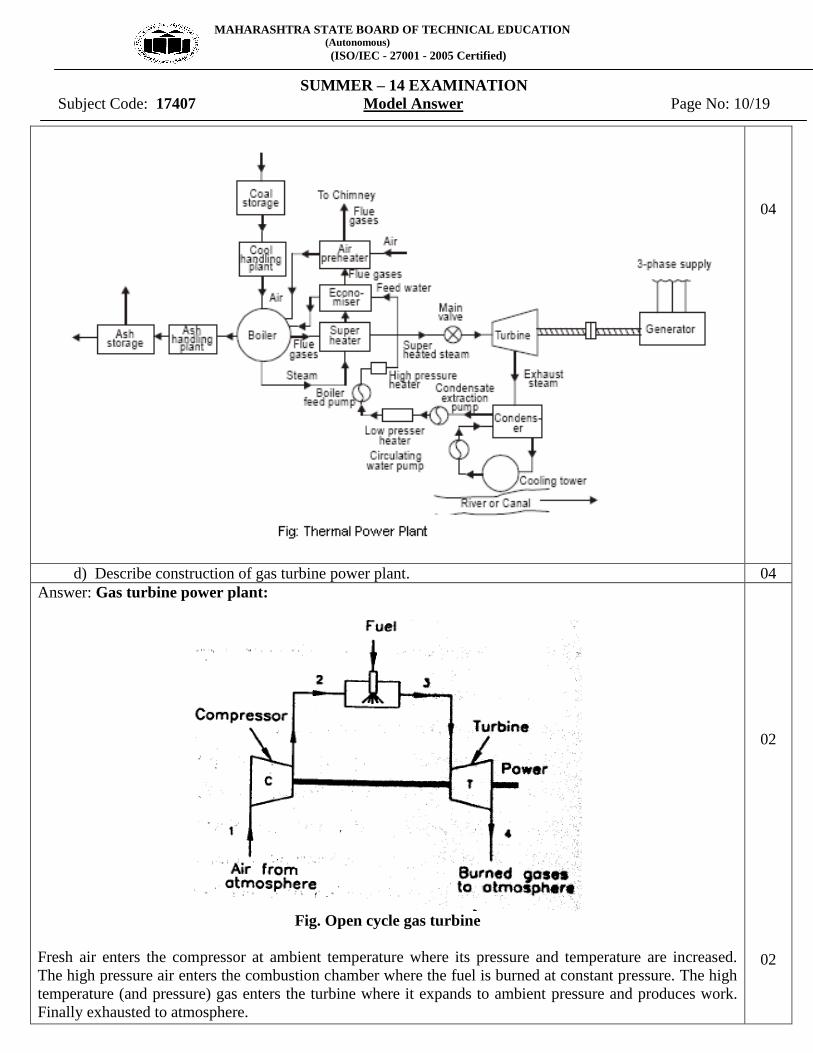
d) Describe construction of gas turbine power plant. 04
Answer: Gas turbine power plant:
Fig. Open cycle gas turbine
Fresh air enters the compressor at ambient temperature where its pressure and temperature are increased.
The high pressure air enters the combustion chamber where the fuel is burned at constant pressure. The high
temperature (and pressure) gas enters the turbine where it expands to ambient pressure and produces work.
Finally exhausted to atmosphere.
02
02
MAHARASHTRA STATE BOARD OF TECHNICAL EDUCATION (Autonomous)
(ISO/IEC - 27001 - 2005 Certified)
SUMMER – 14 EXAMINATION
Subject Code: 17407 Model Answer Page No: 11/19
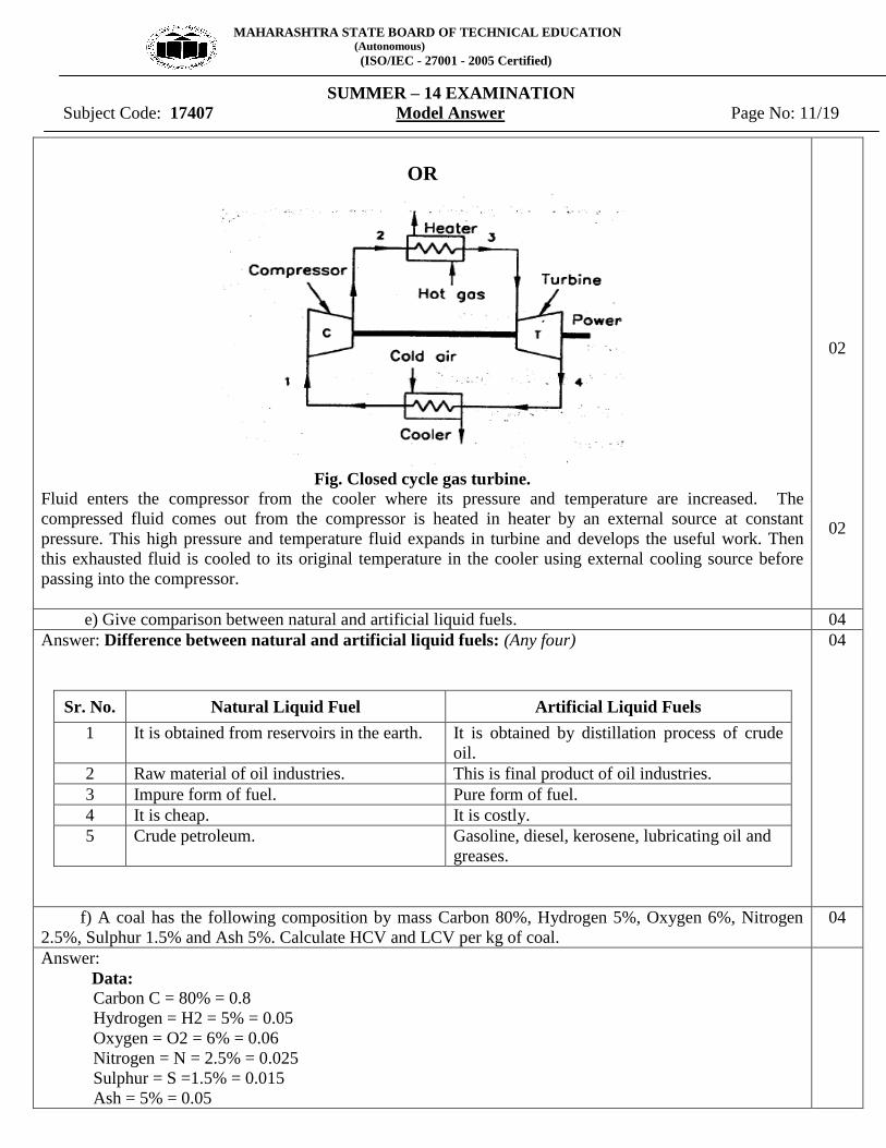
OR
Fig. Closed cycle gas turbine.
Fluid enters the compressor from the cooler where its pressure and temperature are increased. The
compressed fluid comes out from the compressor is heated in heater by an external source at constant
pressure. This high pressure and temperature fluid expands in turbine and develops the useful work. Then
this exhausted fluid is cooled to its original temperature in the cooler using external cooling source before
passing into the compressor.
02
02
e) Give comparison between natural and artificial liquid fuels. 04
Answer: Difference between natural and artificial liquid fuels: (Any four)
Sr. No. Natural Liquid Fuel Artificial Liquid Fuels
1 It is obtained from reservoirs in the earth. It is obtained by distillation process of crude
oil.
2 Raw material of oil industries. This is final product of oil industries.
3 Impure form of fuel. Pure form of fuel.
4 It is cheap. It is costly.
5 Crude petroleum. Gasoline, diesel, kerosene, lubricating oil and
greases.
04
f) A coal has the following composition by mass Carbon 80%, Hydrogen 5%, Oxygen 6%, Nitrogen
2.5%, Sulphur 1.5% and Ash 5%. Calculate HCV and LCV per kg of coal.
04
Answer:
Data:
Carbon C = 80% = 0.8
Hydrogen = H2 = 5% = 0.05
Oxygen = O2 = 6% = 0.06
Nitrogen = N = 2.5% = 0.025
Sulphur = S =1.5% = 0.015
Ash = 5% = 0.05

MAHARASHTRA STATE BOARD OF TECHNICAL EDUCATION (Autonomous)
(ISO/IEC - 27001 - 2005 Certified)
SUMMER – 14 EXAMINATION
Subject Code: 17407 Model Answer Page No: 12/19
Dulong’s formula:
H.C.V. of coal = 33800 C + 144500 ( H2 - O2/8 ) + 9300 S KJ / Kg
=33800 x 0.8 + 144500 (0.05 - 0.06/8) + 9300 x 0.015
= 33320.75 KJ / Kg
L.C.V. of coal = H.C.V.- 9H2 x 2442 KJ / Kg
= 33320.75 – 9 x 0.05 x 2442
= 32221.85 KJ / Kg
02
02
4 Attempt any TWO of the following : 16
a) Describe with neat sketch construction and working Nuclear Power Plant. 08
Answer: Nuclear Power Plant:
Fig. Nuclear Power Plant
The basic components of Nuclear Power Plant are shown in the above fig. Steam is generated in the nuclear
reactor of Nuclear Power Plant by using heat generated by nuclear reaction. The steam generated is passed
through steam turbine where part of its thermal energy is converted into mechanical energy which is further
used for generating electric power. The steam coming out of steam turbine is condensed in condenser and
condensate is supplied back to the nuclear reactor with the help of feed pump and cycle is repeated.
04
04
b) Explain ultimate analysis and proximate analysis of coal. Explain H.C.V. and L.C.V. of fuels.
08
Answer:
Ultimate Analysis: Ultimate analysis is complete breakdown of coal into chemical constituents. This analysis
is important for large scale trials. It serves the basis for calculation of the amount of air required for
complete combustion of 1kg of fuel. It gives percentage content on mass basis of carbon, hydrogen,
oxygen, Sulpher and ash. We are able to calculate the Calorific value of coal.
02

MAHARASHTRA STATE BOARD OF TECHNICAL EDUCATION (Autonomous)
(ISO/IEC - 27001 - 2005 Certified)
SUMMER – 14 EXAMINATION
Subject Code: 17407 Model Answer Page No: 13/19
Proximate Analysis:
Proximate analysis is complete breakdown of coal into physical constituents without
knowledge of analytical chemistry. This analysis made by means of a chemical balance &
temperature control Furnace. The component in the analysis is fixed carbon volatile matter, moisture
& ash. This is used to calculate the heating value of coal.
H.C.V. of Fuel:
Higher calorific value of fuel is defined as amount of heat energy obtain by the complete
combustion of 1kg of fuel, when the products of its combustion are cooled down to the temperature
of supplied air.
L.C.V. of Fuel:
When heat absorbed or carried away by the product of combustion is not recovered &
steam is formed during combustion is not condensed. Then the amount of heat obtain per kg of fuel is
known as lower calorific value of fuel.
02
02
02
c) Describe with neat sketch construction and working of Bomb calorimeter. Write Dulong’s formula
and state its use.
08
Answer: Bomb calorimeter:
Fig : Bomb calorimeter
04

MAHARASHTRA STATE BOARD OF TECHNICAL EDUCATION (Autonomous)
(ISO/IEC - 27001 - 2005 Certified)
SUMMER – 14 EXAMINATION
Subject Code: 17407 Model Answer Page No: 14/19
The calorific valve of solid and liquid fuels is determined in the laboratory by ‘Bomb calorimeter’ It is so
named shape resembles that of bomb .Fig shows the schematic sketch of bomb calorimeter.
Construction :
The calorimeter is made of austenitic steel which provides considerable resistant to corrosion and enables it
to withstand high pressure. In the calorimeter use of a strong cylindrical bomb in which combustion occurs.
The bomb has two values at the top. One supplies oxygen to the bomb and other releases the exhaust gases.
A crucible in which a weighed quantity of fuel sample is burnt is arranged between the two electrodes as
shown in fig. The calorimeter is fitted with water jacket which surrounds the bomb To reduce the losses due
to radiation calorimeter is further provided with a jacket of water and air. A stirrer for keeping the
temperature of water uniform and a thermometer the temperature up to accuracy of 0.0010 C is fitted through
the lid of the calorimeter.
The heat released by the fuel on combustion is absorbed by the surrounding water and the calorimeter. From
the above data the calorific value of the fuel can be found.
Dulong’s formula used to calculate the theoretical calorific value of fuel if ultimate analysis is
available and the calorific value of elementary combustibles are known.
Theoretical calorific Value of fuel =33800 C + 144500 ( - ) + 9300 S kJ/kg
Where C, H2 O2 & S repents the mass of carbon, hydrogen, oxygen and sulfur in kJ/Kg
02
02
5) Attempt any TWO of the following : 16
a) Derive relation between P, V and T during adiabatic process. 08
Answer:
Pressure ( P ) , Volume ( V ) & Temperature ( T ) relation for adiabatic process:
For adiabatic Process,
=C
=
= ( …………… (1)
From general gas equation
= C
=
02

MAHARASHTRA STATE BOARD OF TECHNICAL EDUCATION (Autonomous)
(ISO/IEC - 27001 - 2005 Certified)
SUMMER – 14 EXAMINATION
Subject Code: 17407 Model Answer Page No: 15/19
= …………….(2)
From (1)
= ……........... (3)
Put equation (3) into equation (2)
=
=
= …………..(4)
From equation (1) & (4)
= ( =
02
02
02
b) Explain with neat sketch two pass down flow surface condenser. State functions of condenser in
steam power plant.
08
Answer: Two pass down flow surface condenser:
It consists of horizontal cast iron cylindrical vessel pack with tubes, through which the cooling water
flows.
The ends of the condenser are cut off by vertical perforated type plates in to which water tubes are fixed.
This is done in such a manner that the leakage of water in to the center condensing space is prevented. The
water tubes pass horizontally through the main condensing space for the steam. The steam enters at the top
& is forced to flow downwards over the tubes due to the suction of the extraction pump at the bottom. The
cooling water flows in one direction through lower half of the tubes & return in opposite direction through
the upper half as shown in figure.
The main advantage of surface condenser is condensate does not mix with cooling water which is used
for cooling steam & convert into water; therefore whole condensate can be the reused in the boiler.
02
= ( =

MAHARASHTRA STATE BOARD OF TECHNICAL EDUCATION (Autonomous)
(ISO/IEC - 27001 - 2005 Certified)
SUMMER – 14 EXAMINATION
Subject Code: 17407 Model Answer Page No: 16/19
Fig. Two pass down flow surface condenser
Functions of condenser in steam power plant:-
i) The increase the turbine output by maintaining backpressure on exhaust side of steam engine or
turbine.
ii) The secondary function of condenser is to supply pure and hot feed water to boiler.
04
02
c) Describe with neat sketch construction and working of centrifugal compressor. 08
Answer: Centrifugal compressor:
Fig. Centrifugal Compressor
Fig. shows centrifugal compressor, it is simple in construction. It consists of rotor (i.e. impeller),
impeller eye and diffuser. In impeller number of curved vanes is fitted symmetrically.
Impeller rotates in an air tight volute casing. The casing is designed that the kinetic energy of the air is
converted into pressure energy before it leaves the casing. Mechanical energy is provided to impeller by
some external means. As impeller rotates it sucks air from impeller eye, increases its pressure due to
centrifugal force and forces the air to flow over diffuser. The pressure of air further increases during its flow
over diffuser. Finally, the air at high pressure is delivering to receiver. The air enters in the impeller radially
and leaves vanes axially.
04
04

MAHARASHTRA STATE BOARD OF TECHNICAL EDUCATION (Autonomous)
(ISO/IEC - 27001 - 2005 Certified)
SUMMER – 14 EXAMINATION
Subject Code: 17407 Model Answer Page No: 17/19
6. Attempt any FOUR of the following 16
a) Explain the air standard efficiency of Carnot and Otto cycle. 04
Answer: (1 mark for formula & 1 for explanation.)
Air standard efficiency of Carnot Cycle:-
η = (T1-T2) / T1
Where, T1= temperature of source
T2= temperature of sink
From this equation, it is quite obvious that if temperature T2 decreases efficiency increases and it becomes
100% if T2 becomes absolute zero.
Air standard efficiency of Otto Cycle:-
1r
11
Where, r = compression ratio
From above equation it is clear that air standard efficiency of otto cycle depends on compression ratio (r).
02
02
b) Enlist sources of air leakage in condenser. 04
Answer: Sources of air leakage in condenser:
i) Air leak through joints and packing.
ii) Air also comes in condenser with the steam.
iii) In jet condensers dissolved air in the cooling water enters the condenser.
04
c) State the necessity of multistaging with intercooling in air compressor. 04
Answer: Necessity of multisatging with intercooling in air compression:
The large pressure ratio gives rise in high compression ratio and high discharged temperature which
produce adverse effect on the efficiency and performance of the system.
In such application efficiency decreases and works done and power increases.
So to get better performance and saving in work and power multisatging with intercooling is necessary.
04

MAHARASHTRA STATE BOARD OF TECHNICAL EDUCATION (Autonomous)
(ISO/IEC - 27001 - 2005 Certified)
SUMMER – 14 EXAMINATION
Subject Code: 17407 Model Answer Page No: 18/19
d) Differentiate between open cycle and closed cycle gas turbine. 04
Answer: Difference between open cycle and closed cycle gas turbine:(Any four)
Sr.No. Open cycle gas turbine Closed cycle gas turbine
1.
2. Only air can be used as a working fluid. Any type of working fluid with better
thermodynamic properties can be used.
3. Maintenance cost is low. Maintenance cost is high.
4. Working fluid replaced continuously. Working fluid circulated continuously.
5. Mass of installation per KW is less. Mass of installation per KW is more.
6. Pure form of fuel should be used. Any type of fuel is used.
7. Heat exchanger is not used. Heat exchanger is used.
8 The turbine blades wear away earlier as it gets
contaminated with air.
It avoids erosion of turbine blade due to
contaminated gases.
9 The exhaust gas from the turbine is exhausted
to the atmosphere.
The exhaust gas from the turbine is passed
into cooling chamber.
10 This system required less space. This system required more space.
11
Since turbine exhaust is discharged into
atmosphere, it is best suited for moving
vehicle.
Since exhaust is cooled by circulated
water, it is best suited for stationary
installation, marine use.
04
e) Explain construction and working of turbojet. 04
Answer: Turbo-jet Engine:
Turbo-jet engine consists of diffuser, compressor, combustion chamber turbine and nozzle.
At entrance air diffuser causes rise in pressure in entering air by slowing it down. A rotary compressor,
which raises the pressure of air further to required value and delivers to the combustion chamber. The
compressor is axial or radial type driven by turbine. In the combustion chamber, fuel is sprayed, as result of
this combustion takes place at constant pressure and the temperature of air is raised. Then this product of
combustion passes into the gas turbine gets expanded and provides necessary power to drive the compressor.
The discharge nozzle in which expansion of gases is completed and thrust of propulsion is produced. The
velocity in the nozzle is grater then flight velocity.
02

MAHARASHTRA STATE BOARD OF TECHNICAL EDUCATION (Autonomous)
(ISO/IEC - 27001 - 2005 Certified)
SUMMER – 14 EXAMINATION
Subject Code: 17407 Model Answer Page No: 19/19
Fig. Turbo-jet Engine
02
f) Describe with neat sketch construction and working of screw compressor. 04
Answer: Screw compressor:
Fig. Screw Compressor
Screw Compressor:-
It consists of two mutually engaged helical grooved rotors which are suitably housed in a casing. Out
of two rotors male rotor is driver and female rotor is a driven.
Male rotor has four lobes and female rotor as six flutes.
During rotation of rotor, air enters and takes space between male and female rotor. This air traps and
moves axially and radically with rotation of rotors and gets compressed due to volume reduction.
Then this air discharged from upward direction. Speed of rotors is different due to different number
of lobes and flutes.
It handles 3.5 to 300 m3/min and maximum pressure ratio of 20. This system requires lubrication.
This compressor is noisy I operation. Used in refrigeration industry.
02
02