Methods for Sensitive Detection of Magneto Optic Kerr Effect
Magneto-Optic Kerr E�ect Microscopy
Tyler A. Hennen∗
Electrical and Computer Engineering Department,
University of Californa, San Diego
9500 Gilman Dr, La Jolla, CA 92093, USA
(Dated: December 9, 2014)
Magnetic domains are introduced as an interesting topic arising in solid state physics witha variety of technological applications. The Magneto-Optic Kerr E�ect (MOKE) is brie�ydiscussed as a microscopy technique for observing domain patterns and dynamics in thinferromagnetic �lms. A recent paper from Phys Rev B is exhibited, in which MOKE imaginglead to insight into an unexpected magnetic hysteresis phenomenon.
INTRODUCTION
Although it was not covered during our coursein Solid State Physics, ferromagnetic ordering isan interesting and important topic arising in thestudy of condensed matter. Many atoms exhibitmagnetic polarization due to the presence of un-paired electrons in their atomic orbitals, whichpossess a magnetic moment due to their spin. Inmost solids, thermal �uctuations tend to orientthe moments of the constituent atoms randomly,so that no net magnetization is observed in thebulk (paramagnetism). However, for a few ma-terials such as iron, nickel, cobalt, and certainalloys, a quantum mechanical e�ect called theexchange interaction can cause the moments tospontaneously align in the absence of a magnetic�eld.
In 1906, even before the exchange interactionwas properly understood, Pierre-Ernest Weisshad correctly postulated that ferromagnetic ma-terials have a tendency to break up into smallregions of uniform magnetization called domains[1]. These domains would in general not sharea common direction of magnetization, and couldcancel out the average magnetization of the ma-terial. The concept of domains explains, for ex-ample, the observation that macroscopic objectcontaining iron, such as a wrench, is not magne-tized even though it is composed of a ferromag-netic material.
Over the past few decades, micromagneticstructure has been a rich area of scienti�c re-search, driven in large part by useful applica-tions. Ferromagnetic materials now pervade our
electronic world. They are used as high perme-ability materials in our RF devices and trans-formers, and as permanent magnets in our gen-erators, motors, etc. They store the majorityof the world's digital information in hard drives,and form the basis for magnetic sensors as usedin recording and elsewhere.
Today, magnetic materials are studied to op-timize their properties for existing applications,and are continuing to be investigated for fu-ture memory storage applications and for use inthe emerging �eld of spintronics. Studying theformation and dynamics of magnetic domainsis highly relevant for such technological appli-cations, and it is now possible to study themthrough direct observation.
MAGNETIC DOMAINS
To understand why magnetic domains areformed, one need only consider the energetics in-volved in a micromagnetic system. Already men-tioned is the exchange interaction energy, whichtends to align nearby moments. Considering a�nite set of discrete moments Mi, the exchangeenergy is given by
Eex = −∑i,j
Jij(Mi ·Mj),
where Jij is the so-called exchange constant be-tween the ith and jth moments, which falls o�rapidly as the distance between moments in-creases. Thus, any misalignment in neighboringmagnetization vectors costs exchange energy. An
2
energy is also imposed by any external magnetic�eld, H, called the Zeeman energy
Ezee = −∑i
Mi ·H,
where M is the magnetization vector. The Zee-man energy tends to align all the Mi with H.There is also the anisotropy energy, which estab-lishes a preferred orientation for M . Anisotropycan be imposed by the crystal (magnetocrys-talline anisotropy), or by magnetostatic �eldsdue to the sample geometry (shape anisotropy).Anisotropy energy can exist in many di�erentforms, but for simplicity consider a simple uni-axial �rst-order anisotropy
Ea =∑i
K sin2 θi
where K is the anisotropy energy, and θi is theangle between Mi and the anisotropy axis. Tocomplete our simpli�ed picture, we �nally havethe stray �eld energy, generated by the diver-gence of the magnetization,
Es =1
2µ0
∫all space
H2ddV,
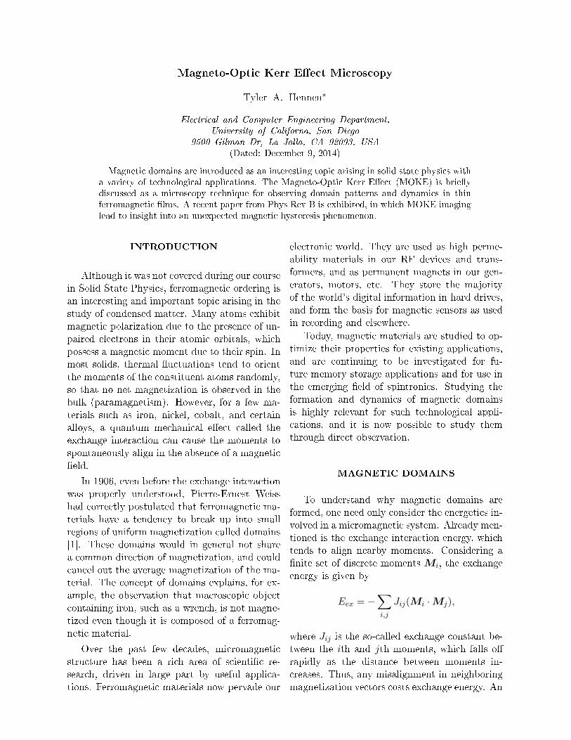
where Hd is the stray �eld.With reference to Fig. 1, we can now con-
ceptually see how it may be energetically favor-able to form domains. The single domain case inFig. 1.a has a low exchange energy, but a highstray �eld energy. The stray �eld energy maybe reduced somewhat by forming the domain inFig. 1.b, at no cost to the anisotropy energy,but by increasing the exchange energy by form-ing a domain wall. Finally, the stray �eld maybe eliminated as in the con�guration of Fig. 1.c,at a price of both anisotropy and exchange en-ergy. The domain formed will depend to a largedegree on the system parameters such as shapeand anisotropy, and on the conditions such asapplied �elds, stress, and temperature.
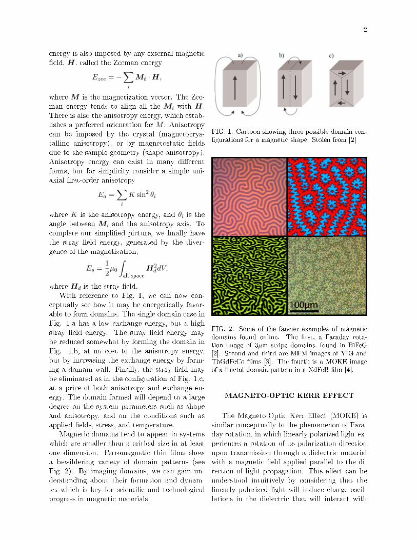
Magnetic domains tend to appear in systemswhich are smaller than a critical size in at leastone dimension. Ferromagnetic thin �lms showa bewildering variety of domain patterns (seeFig. 2). By imaging domains, we can gain un-derstanding about their formation and dynam-ics which is key for scienti�c and technologicalprogress in magnetic materials.
FIG. 1. Cartoon showing three possible domain con-�gurations for a magnetic shape. Stolen from [2]
FIG. 2. Some of the fancier examples of magneticdomains found online. The �rst, a Faraday rota-tion image of 3µm stripe domains, found in BiFeG[2]. Second and third are MFM images of YIG andTbGdFeCo �lms [3]. The fourth is a MOKE imageof a fractal domain pattern in a NdFeB �lm [4].
MAGNETO-OPTIC KERR EFFECT
The Magneto-Optic Kerr E�ect (MOKE) issimilar conceptually to the phenomenon of Fara-day rotation, in which linearly polarized light ex-periences a rotation of its polarization directionupon transmission through a dielectric materialwith a magnetic �eld applied parallel to the di-rection of light propagation. This e�ect can beunderstood intuitively by considering that thelinearly polarized light will induce charge oscil-lations in the dielectric that will interact with
3
the internal magnetic �eld via the Lorentz force.The result is a perpendicular contribution to theelectric �eld, leading to a polarization rotationproportional to the magnetic �eld.
More commonly, the e�ect is understood asarising from a di�erence in the index of refractionfor circularly polarized light of opposite handed-ness (Circular Birefringence). A beam of linearlypolarized light may be decomposed into two cir-cularly polarized beams of left and right hand-edness. The medium will then introduce a phaseshift between the circular beams, and when com-bined they will form a linearly polarized beamwith the polarization direction rotated throughsome angle.
The Faraday e�ect used as an experimentaltechnique to probe magnetic �elds requires thata sample be transparent at the light frequencyused. However, for magnetic materials this israrely the case. Metals in general have a penetra-tion depth for light that is approximately 20 nm[5]. Materials that are thicker than the penetra-tion depth may be investigated in the re�ectiongeometry, and when this is done the e�ect is re-ferred to as MOKE. The e�ect in re�ection isvery small (< 0.1◦), due to the small distancetraveled in the magnetic medium, and requiressensitive optical and electronic elements to de-tect.
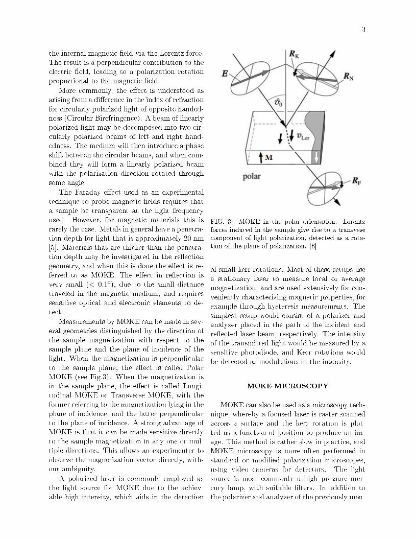
Measurements by MOKE can be made in sev-eral geometries distinguished by the direction ofthe sample magnetization with respect to thesample plane and the plane of incidence of thelight. When the magnetization is perpendicularto the sample plane, the e�ect is called PolarMOKE (see Fig.3). When the magnetization isin the sample plane, the e�ect is called Longi-tudinal MOKE or Transverse MOKE, with theformer referring to the magnetization lying in theplane of incidence, and the latter perpendicularto the plane of incidence. A strong advantage ofMOKE is that it can be made sensitive directlyto the sample magnetization in any one or mul-tiple directions. This allows an experimenter toobserve the magnetization vector directly, with-out ambiguity.
A polarized laser is commonly employed asthe light source for MOKE due to the achiev-able high intensity, which aids in the detection
FIG. 3. MOKE in the polar orientation. Lorentzforces induced in the sample give rise to a transvesecomponent of light polarization, detected as a rota-tion of the plane of polarization. [6]
of small kerr rotations. Most of these setups usea stationary laser to measure local or averagemagnetization, and are used extensively for con-veniently characterizing magnetic properties, forexample through hysteresis measurements. Thesimplest setup would consist of a polarizer andanalyzer placed in the path of the incident andre�ected laser beam, respectively. The intensityof the transmitted light would be measured by asensitive photodiode, and Kerr rotations wouldbe detected as modulations in the intensity.
MOKE MICROSCOPY
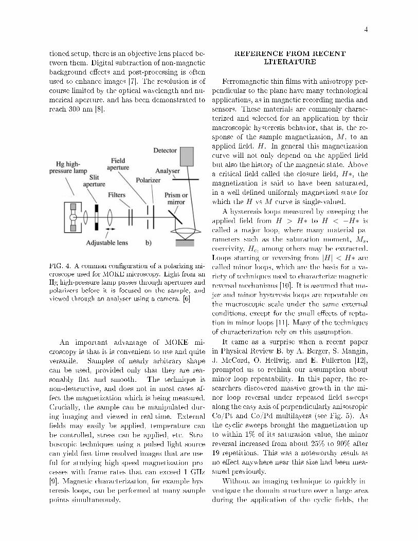
MOKE can also be used as a microscopy tech-nique, whereby a focused laser is raster scannedacross a surface and the kerr rotation is plot-ted as a function of position to produce an im-age. This method is rather slow in practice, andMOKE microscopy is more often performed instandard or modi�ed polarization microscopes,using video cameras for detectors. The lightsource is most commonly a high pressure mer-cury lamp, with suitable �lters. In addition tothe polarizer and analyzer of the previously men-
4
tioned setup, there is an objective lens placed be-tween them. Digital subtraction of non-magneticbackground e�ects and post-processing is oftenused to enhance images [7]. The resolution is ofcourse limited by the optical wavelength and nu-merical aperture, and has been demonstrated toreach 300 nm [8].
FIG. 4. A common con�guration of a polarizing mi-croscope used for MOKE microscopy. Light from anHg high-pressure lamp passes through apertures andpolarizers before it is focused on the sample, andviewed through an analyser using a camera. [6]
An important advantage of MOKE mi-croscopy is that it is convenient to use and quiteversatile. Samples of nearly arbitrary shapecan be used, provided only that they are rea-sonably �at and smooth. The technique isnon-destructive, and does not in most cases af-fect the magnetization which is being measured.Crucially, the sample can be manipulated dur-ing imaging and viewed in real-time. External�elds may easily be applied, temperature canbe controlled, stress can be applied, etc. Stro-boscopic techniques using a pulsed light sourcecan yield fast time-resolved images that are use-ful for studying high-speed magnetization pro-cesses with frame rates that can exceed 1 GHz[9]. Magnetic characterization, for example hys-teresis loops, can be performed at many samplepoints simultaneously.
REFERENCE FROM RECENT
LITERATURE
Ferromagnetic thin �lms with anisotropy per-pendicular to the plane have many technologicalapplications, as in magnetic recording media andsensors. These materials are commonly charac-terized and selected for an application by theirmacroscopic hysteresis behavior, that is, the re-sponse of the sample magnetization, M , to anapplied �eld, H. In general this magnetizationcurve will not only depend on the applied �eldbut also the history of the magnetic state. Abovea critical �eld called the closure �eld, H∗, themagnetization is said to have been saturated,in a well de�ned uniformly magnetized state forwhich the H vs M curve is single-valued.
A hysteresis loops measured by sweeping theapplied �eld from H > H∗ to H < −H∗ iscalled a major loop, where many material pa-rameters such as the saturation moment, Ms,coercivity, Hc, among others may be extracted.Loops starting or reversing from |H| < H∗ arecalled minor loops, which are the basis for a va-riety of techniques used to characterize magneticreversal mechanisms [10]. It is assumed that ma-jor and minor hysteresis loops are repeatable onthe macroscopic scale under the same externalconditions, except for the small e�ects of repta-tion in minor loops [11]. Many of the techniquesof characterization rely on this assumption.
It came as a surprise when a recent paperin Physical Review B, by A. Berger, S. Mangin,J. McCord, O. Hellwig, and E. Fullerton [12],prompted us to rethink our assumption aboutminor loop repeatability. In this paper, the re-searchers discovered massive growth in the mi-nor loop reversal under repeated �eld sweepsalong the easy axis of perpendicularly anisotropicCo/Pt and Co/Pd multilayers (see Fig. 5). Asthe cyclic sweeps brought the magnetization upto within 1% of its saturation value, the minorreversal increased from about 25% to 90% after19 repetitions. This was a noteworthy result asno e�ect anywhere near this size had been mea-sured previously.
Without an imaging technique to quickly in-vestigate the domain structure over a large areaduring the application of the cyclic �elds, the
5
FIG. 5. Massive cumulative minor loop growth oc-curs in perpendicular Co/Pt multilayers through ap-plication of a cyclic magnetic �eld. [12]
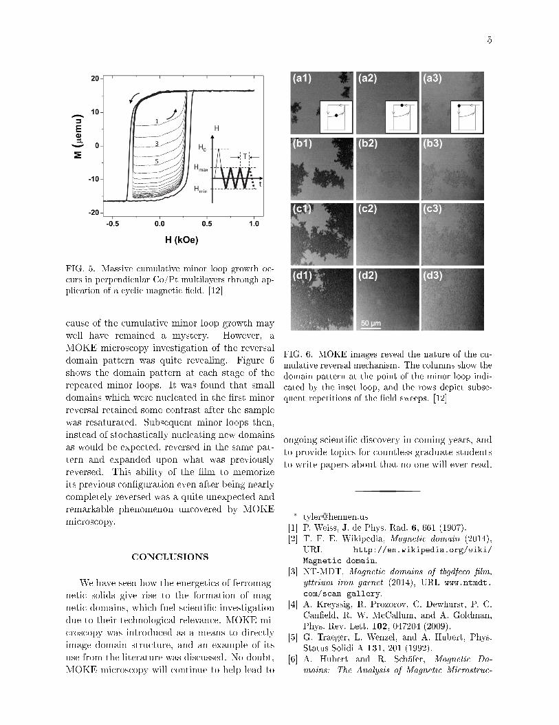
cause of the cumulative minor loop growth maywell have remained a mystery. However, aMOKE microscopy investigation of the reversaldomain pattern was quite revealing. Figure 6shows the domain pattern at each stage of therepeated minor loops. It was found that smalldomains which were nucleated in the �rst minorreversal retained some contrast after the samplewas resaturated. Subsequent minor loops then,instead of stochastically nucleating new domainsas would be expected, reversed in the same pat-tern and expanded upon what was previouslyreversed. This ability of the �lm to memorizeits previous con�guration even after being nearlycompletely reversed was a quite unexpected andremarkable phenomenon uncovered by MOKEmicroscopy.
CONCLUSIONS
We have seen how the energetics of ferromag-netic solids give rise to the formation of mag-netic domains, which fuel scienti�c investigationdue to their technological relevance. MOKE mi-croscopy was introduced as a means to directlyimage domain structure, and an example of itsuse from the literature was discussed. No doubt,MOKE microscopy will continue to help lead to
FIG. 6. MOKE images reveal the nature of the cu-mulative reversal mechanism. The columns show thedomain pattern at the point of the minor loop indi-cated by the inset loop, and the rows depict subse-quent repetitions of the �eld sweeps. [12]
ongoing scienti�c discovery in coming years, andto provide topics for countless graduate studentsto write papers about that no one will ever read.
∗ [email protected][1] P. Weiss, J. de Phys. Rad. 6, 661 (1907).[2] T. F. E. Wikipedia, Magnetic domain (2014),
URL http://en.wikipedia.org/wiki/
Magnetic_domain.[3] NT-MDT, Magnetic domains of tbgdfeco �lm,
yttrium iron garnet (2014), URL www.ntmdt.
com/scan-gallery.[4] A. Kreyssig, R. Prozorov, C. Dewhurst, P. C.
Can�eld, R. W. McCallum, and A. Goldman,Phys. Rev. Lett. 102, 047204 (2009).
[5] G. Traeger, L. Wenzel, and A. Hubert, Phys.Status Solidi A 131, 201 (1992).
[6] A. Hubert and R. Schäfer, Magnetic Do-
mains: The Analysis of Magnetic Microstruc-

6
tures (Springer, 1998), ISBN 9783540641087.[7] R. Schäfer, Investigation of Domains and Dy-
namics of Domain Walls by the Magneto-optical
Kerr-e�ect (John Wiley & Sons, Ltd, 2007),chap. 3.5, pp. 1464�1564, ISBN 9780470022184.
[8] F. Schmidt and A. Hubert, J. Magn. Magn. Mat.61, 307 (1986).
[9] M. Kryder, P. Koeppe, and F. Liu, IEEE Trans.Magn. 26, 2995 (1990).
[10] C. Leighton, Physics 3, 79 (2010).[11] V. G. Lewis, P. I. Mayo, and K. O�Grady, Jour-
nal of Applied Physics 73, 6656 (1993).[12] A. Berger, S. Mangin, J. McCord, O. Hell-
wig, and E. Fullerton, Phys. Rev. B 82, 104423(2010), URL http://link.aps.org/doi/10.
1103/PhysRevB.82.104423.