Magnetic targeting of microbubbles against physiologically...
13
rsfs.royalsocietypublishing.org Research Cite this article: Owen J, Rademeyer P, Chung D, Cheng Q, Holroyd D, Coussios C, Friend P, Pankhurst QA, Stride E. 2015 Magnetic targeting of microbubbles against physiologically relevant flow conditions. Interface Focus 5: 20150001. http://dx.doi.org/10.1098/rsfs.2015.0001 One contribution of 13 to a theme issue ‘Amazing (cavitation) bubbles: great potentials and challenges’. Subject Areas: biomedical engineering, medical physics Keywords: microbubbles, magnetic targeting, ultrasound, drug delivery, contrast agent, imaging Author for correspondence: Eleanor Stride e-mail: [email protected] Electronic supplementary material is available at http://dx.doi.org/10.1098/rsfs.2015.0001 or via http://rsfs.royalsocietypublishing.org. Magnetic targeting of microbubbles against physiologically relevant flow conditions Joshua Owen 1 , Paul Rademeyer 1 , Daniel Chung 1,2 , Qian Cheng 1 , David Holroyd 1,2 , Constantin Coussios 1 , Peter Friend 2 , Quentin A. Pankhurst 3,4 and Eleanor Stride 1 1 Institute of Biomedical Engineering, Department of Engineering Science, University of Oxford, Old Road Campus Research Building, Oxford OX3 7DQ, UK 2 Nuffield Department of Surgical Sciences, University of Oxford, John Radcliffe Hospital, Oxford OX3 9DU, UK 3 Healthcare Biomagnetics Laboratory, University College London, 21 Albemarle Street, London W1S 4BS, UK 4 Institute of Biomedical Engineering, University College London, Gower Street, London WC1E 6BT, UK The localization of microbubbles to a treatment site has been shown to be essential to their effectiveness in therapeutic applications such as targeted drug delivery and gene therapy. A variety of different strategies for achieving localization has been investigated, including biochemical targeting, acoustic radiation force, and the incorporation of superparamagnetic nanoparticles into microbubbles to enable their manipulation using an externally applied magnetic field. The third of these strategies has the advantage of concentrating microbubbles in a target region without exposing them to ultrasound, and can be used in conjunction with biochemical targeting to achieve greater speci- ficity. Magnetic microbubbles have been shown to be effective for therapeutic delivery in vitro and in vivo. Whether this technique can be successfully applied in humans however remains an open question. The aim of this study wasto determine the range of flow conditions under which targeting could be achieved. In vitro results indicate that magnetic microbubbles can be retained using clinically acceptable magnetic fields, for both the high shear rates (approx. 10 4 s 21 ) found in human arterioles and capillaries, and the high flow rates (approx. 3.5 ml s 21 ) of human arteries. The potential for human in vivo microbubble retention was further demonstrated using a perfused porcine liver model. 1. Introduction Advances in the development of new types of pharmaceutical product have resulted in rapidly growing demand for more effective delivery systems. New delivery methods for existing products are similarly being sought to mitigate the impact of patent expiration [1]. While systemic delivery of a drug, e.g. by intra- venous or oral administration has significant advantages in terms of convenience and cost, it can lead to harmful side effects [2]. Moreover, conventional adminis- tration methods are simply not suitable for several classes of therapeutic compound. These include poorly soluble drugs and large molecules such as pro- teins, which often produce a negligible therapeutic effect when delivered orally or intravenously [3]. There are three criteria that any drug delivery system should fulfil to pro- vide maximum therapeutic efficacy with minimal unwanted side effects: (i) that it prevents unwanted damage and degradation of the therapeutic material during circulation, (ii) that it ensures the majority of the material is maintained at the desired location(s), and (iii) that it promotes entry of the therapeutic compound into the target tissue [4]. & 2015 The Authors. Published by the Royal Society under the terms of the Creative Commons Attribution License http://creativecommons.org/licenses/by/4.0/, which permits unrestricted use, provided the original author and source are credited. on July 4, 2018 http://rsfs.royalsocietypublishing.org/ Downloaded from on July 4, 2018 http://rsfs.royalsocietypublishing.org/ Downloaded from on July 4, 2018 http://rsfs.royalsocietypublishing.org/ Downloaded from
Transcript of Magnetic targeting of microbubbles against physiologically...
on July 4, 2018http://rsfs.royalsocietypublishing.org/Downloaded from on July 4, 2018http://rsfs.royalsocietypublishing.org/Downloaded from on July 4, 2018http://rsfs.royalsocietypublishing.org/Downloaded from
rsfs.royalsocietypublishing.org
ResearchCite this article: Owen J, Rademeyer P,
Chung D, Cheng Q, Holroyd D, Coussios C,
Friend P, Pankhurst QA, Stride E. 2015
Magnetic targeting of microbubbles against
physiologically relevant flow conditions.
Interface Focus 5: 20150001.
http://dx.doi.org/10.1098/rsfs.2015.0001
One contribution of 13 to a theme issue
‘Amazing (cavitation) bubbles: great potentials
and challenges’.
Subject Areas:biomedical engineering, medical physics
Keywords:microbubbles, magnetic targeting, ultrasound,
drug delivery, contrast agent, imaging
Author for correspondence:Eleanor Stride
e-mail: [email protected]
& 2015 The Authors. Published by the Royal Society under the terms of the Creative Commons AttributionLicense http://creativecommons.org/licenses/by/4.0/, which permits unrestricted use, provided the originalauthor and source are credited.
Electronic supplementary material is available
at http://dx.doi.org/10.1098/rsfs.2015.0001 or
via http://rsfs.royalsocietypublishing.org.
Magnetic targeting of microbubblesagainst physiologically relevantflow conditions
Joshua Owen1, Paul Rademeyer1, Daniel Chung1,2, Qian Cheng1,David Holroyd1,2, Constantin Coussios1, Peter Friend2, Quentin A. Pankhurst3,4
and Eleanor Stride1
1Institute of Biomedical Engineering, Department of Engineering Science, University of Oxford, Old Road CampusResearch Building, Oxford OX3 7DQ, UK2Nuffield Department of Surgical Sciences, University of Oxford, John Radcliffe Hospital, Oxford OX3 9DU, UK3Healthcare Biomagnetics Laboratory, University College London, 21 Albemarle Street, London W1S 4BS, UK4Institute of Biomedical Engineering, University College London, Gower Street, London WC1E 6BT, UK
The localization of microbubbles to a treatment site has been shown to be
essential to their effectiveness in therapeutic applications such as targeted
drug delivery and gene therapy. A variety of different strategies for achieving
localization has been investigated, including biochemical targeting, acoustic
radiation force, and the incorporation of superparamagnetic nanoparticles
into microbubbles to enable their manipulation using an externally applied
magnetic field. The third of these strategies has the advantage of concentrating
microbubbles in a target region without exposing them to ultrasound, and
can be used in conjunction with biochemical targeting to achieve greater speci-
ficity. Magnetic microbubbles have been shown to be effective for therapeutic
delivery in vitro and in vivo. Whether this technique can be successfully applied
in humans however remains an open question. The aim of this study was to
determine the range of flow conditions under which targeting could be
achieved. In vitro results indicate that magnetic microbubbles can be retained
using clinically acceptable magnetic fields, for both the high shear rates
(approx. 104 s21) found in human arterioles and capillaries, and the high
flow rates (approx. 3.5 ml s21) of human arteries. The potential for human
in vivo microbubble retention was further demonstrated using a perfused
porcine liver model.
1. IntroductionAdvances in the development of new types of pharmaceutical product have
resulted in rapidly growing demand for more effective delivery systems. New
delivery methods for existing products are similarly being sought to mitigate
the impact of patent expiration [1]. While systemic delivery of a drug, e.g. by intra-
venous or oral administration has significant advantages in terms of convenience
and cost, it can lead to harmful side effects [2]. Moreover, conventional adminis-
tration methods are simply not suitable for several classes of therapeutic
compound. These include poorly soluble drugs and large molecules such as pro-
teins, which often produce a negligible therapeutic effect when delivered orally or
intravenously [3].
There are three criteria that any drug delivery system should fulfil to pro-
vide maximum therapeutic efficacy with minimal unwanted side effects:
(i) that it prevents unwanted damage and degradation of the therapeutic
material during circulation, (ii) that it ensures the majority of the material
is maintained at the desired location(s), and (iii) that it promotes entry of the
therapeutic compound into the target tissue [4].
rsfs.royalsocietypublishing.orgInterface
Focus5:20150001
2
on July 4, 2018http://rsfs.royalsocietypublishing.org/Downloaded from
There have been a large number of studies in recent years
demonstrating the considerable potential of coated microbubbles
as agents for drug delivery [5,6]. Long established as efficient
contrast agents for ultrasound imaging [7], microbubbles have
been widely shown to improve both extravasation and the
cellular uptake of therapeutic material [8–10]. However, for
microbubble-enhanced delivery to be effective, there must be a
sufficient concentration of microbubbles at the target site.
Simply increasing the systemic microbubble concentration is
undesirable as it can increase the risk of embolism and shield
target tissue from ultrasound exposure [11].
To address this challenge, various strategies for targeting
microbubbles to specific sites have been explored. Microbubbles
have been successfully targeted in vitro via electrostatic coup-
ling [12], molecular binding through the use of antibodies
and proteins [13], and acoustic radiation force [14]. However,
efficient targeting of microbubbles still represents a consi-
derable challenge in vivo, as the surface architectures that
maximize targeting typically also increase the presentation of
immunogenic compounds, which can lead to early particle
clearance or a hypersensitivity response [5]. An alternative
method of targeting which has shown considerable potential
uses microbubbles with superparamagnetic nanoparticles
incorporated into their coating.
The use of both micro- and nano-scale magnetic particles
has been explored for the delivery of therapeutic agents for sev-
eral decades [15–18], and more recently for gene delivery [19].
In 2000, Soetanto & Watarai [20,21] demonstrated electrostatic
conjugation of stearate-coated magnetic microparticles to
microbubbles stabilized with the same material via calcium
ion binding. Magnetic microbubble formulations have since
been developed for dual-purpose ultrasound and magnetic
resonance imaging (MRI) contrast agents, and as drug delivery
vehicles [22–25]. In 2009, Stride et al. [26] published a study in
which magnetic microbubbles were used for gene delivery to
Chinese hamster ovary cells. Magnetic microbubbles, non-
magnetic microbubbles and/or magnetic liquid droplets
were co-injected with naked plasmid DNA encoding for luci-
ferase and the cells exposed to a magnetic field, ultrasound
or both. It was found that the highest rates of transfection
were achieved with simultaneous exposure to ultrasound
and a magnetic field with magnetic microbubbles [26]. This for-
mulation was also successfully used to deliver a
bioluminescent marker to the right lung of a mouse in vivo[27]. Vlaskou et al. [24] similarly used magnetic and acousti-
cally active lipospheres to deliver therapeutic agents in vitroand in vivo under the application of ultrasound.
Magnetic microbubbles have thus demonstrated consider-
able potential as delivery agents, but it is unknown yet
whether they are capable of being targeted under the flow con-
ditions typically found in the human body. Evidence of
targeting in small animal models is of limited relevance, as suc-
cessful targeting of magnetic particles requires the combination
of magnetic field strength and gradient to be sufficiently high at
the relevant tissue depth. In most cases this will be significantly
greater in humans. Moreover, there is a rapid reduction in
magnetic force with distance from the magnet.
The aim of this study was therefore to investigate targeting
of magnetic microbubbles under flow conditions and length
scales relevant to the human body. The ability of microbubbles
to be retained was determined in vessels of different diameters
and under flow conditions ranging from the high shear rates
found in the capillaries to the high flow rates found in the
arteries. The impact of substituting the suspending liquid for
whole blood was then examined, and finally a preliminary
experiment was performed in a perfused porcine liver.
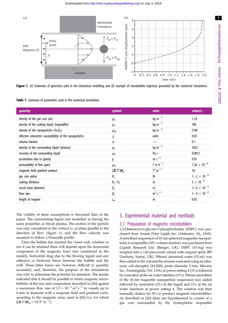
2. Theoretical modellingPrior to commencing the experimental work, numerical
simulations were performed to estimate the flow conditions
under which magnetic targeting of microbubbles should be
theoretically possible. From conservation of momentum, the
vertical motion of a single spherical particle suspended in
an incompressible, single-phase Newtonian liquid under-
going steady, laminar flow in a horizontal cylindrical vessel
in the presence of a magnetic field with constant gradient
(figure 1) may be written as
meff€y ¼ FB þ FD � Fw � FMy, ð2:1Þ
where meff is the effective mass of the particle and FB, FD, Fw
and FMy refer to the vertical forces acting on it due to
buoyancy, viscous drag, its weight and the magnetic field
gradient, respectively.
If the particle is a bubble with a gas core of radius R1 sur-
rounded by a liquid shell of thickness R22 R1 that contains a
volume fraction a of magnetic nanoparticles then equation
(2.1) may be re written as
4pR32
3rGþ
rL
2
� �€y¼ 4pgrLR3
2
3þ 6pR2mL _y
�4pgðrGR3
1þðR32�R3
1Þðð1�aÞroþarnpÞÞ3
�4px½ðB �rÞB�yaðR3
2�R31Þ
3m0
,
ð2:2Þ
where rG is the density of the gas, rL and mL are the density
and viscosity of the surrounding liquid, respectively, ro is the
density of the shell material, rnp is the density of the magnetic
nanoparticles and x is their effective volumetric suscepti-
bility, B is the magnetic field, g is the acceleration due to
gravity and m0 is the permeability of free space.
Solving this system of equations enables the time required
for the bubble to travel from its initial position in the vessel to
the wall closest to the magnet to be determined. Provided this
time tr is shorter than the time taken for the bubble to flow
out of the target region defined by the distance over which
the magnet provides sufficient force, Lm then the bubble has
the potential to be retained (i.e. it is necessary that _xtr , Lm).
Simulations were performed using a fourth order Runge–
Kutta solver in the Matlabw numerical computing environment
(2012B, The MathWorks, Natick, MA, USA). A range of vari-
ables describing different combinations of bubble size and
magnetic nanoparticle content, liquid flow rate, vessel diameter
and region, and magnitude of constant magnetic force was used
(table 1). The parameters for the magnetic microbubbles were
based on the formulation published in [26] (see §3.1) and the
ranges of diameters and volume flow rates were selected to
mimic conditions in different types of blood vessel (see §3.2).
It was assumed that the bubble would remain spherical
and there would be no exchange of either gas or coating
material with the surroundings. The bubble was treated as
an incompressible particle and interactions with other
bubbles and/or blood components were not considered.
tubediameter, D
entrypoint
d
r
ultrasoundtransducer
magnet
FB + FD
FW + FMy
5
4
3
2
1
0
–10 0.2 0.4 0.6 0.8 1.0 1.2 1.4 1.6 1.8 2.0
bubb
le Y
-axi
s di
spla
cem
ent (
µm)
time (ms)
(a) (b)
Figure 1. (a) Schematic of geometry used in the theoretical modelling and (b) example of microbubble trajectory generated by the numerical simulations.
Table 1. Summary of parameters used in the numerical simulations.
quantity symbol units value(s)
density of the gas core (air) rG kg m23 1.24
density of the coating liquid (isoparaffin) ro kg m23 700
density of the nanoparticles (Fe3O4) rnp kg m23 5100
effective volumetric susceptibility of the nanoparticles x units 0.85
volume fraction a — 0.1
density of the surrounding liquid ( plasma) rL kg m23 1025
viscosity of the surrounding liquid mL Pa s 0.0015
acceleration due to gravity g m s22 9.81
permeability of free space m0 T m A21 1.26 � 1026
magnetic field gradient product [(B.r)B]y T2 m21 18
gas core radius R1 M 1 – 2 � 1026
coating thickness R2 – R1 m 5 � 1028
vessel inner diameter Dv m 1 – 6 � 1023
flow rate QL m3 s21 1 – 4 � 1026
length of magnet Lm m 0.05
rsfs.royalsocietypublishing.orgInterface
Focus5:20150001
3
on July 4, 2018http://rsfs.royalsocietypublishing.org/Downloaded from
The validity of these assumptions is discussed later in the
paper. The surrounding liquid was modelled as having the
same properties as blood plasma. The motion of the particle
was only considered in the vertical (x, y) plane parallel to the
direction of flow (figure 1), and the flow velocity was
assumed to follow a Poiseuille profile.
Once the bubble has reached the vessel wall, whether or
not it can be retained there will depend upon the horizontal
component of the magnetic force (not considered in the
model), horizontal drag due to the flowing liquid and any
adhesive or frictional forces between the bubble and the
wall. These latter forces are, however, difficult to quantify
accurately, and, therefore, the purpose of the simulations
was only to determine the potential for retention. The results
indicated that it should be possible to retain magnetic micro-
bubbles of the size and composition described in [26] against
a maximum flow rate of 3.3 � 1023 m3 s21 in vessels up to
6 mm in diameter with a magnetic field and gradient corre-
sponding to the magnetic array used in [26] (i.e. for which
[(B.r)B]y ¼ 18 T2 m21).
3. Experimental material and methods3.1. Preparation of magnetic microbubbles1,2-Distearoyl-sn-glycero-3-phosphocholine (DSPC) was pur-
chased from Avanti Polar Lipids Inc. (Alabaster, AL, USA).
A ferrofluid suspension of 10 nm spherical magnetite nanopar-
ticles in isoparaffin (10% volume fraction) was purchased from
Liquids Research Ltd. (Bangor, UK). DSPC (15 mg) was
weighed into a vial previously rinsed with surgical spirit (BP
Unichem, Surrey, UK). Filtered deionized water (15 ml) was
then added to the vial and the mixture sonicated using an ultra-
sonic cell disruptor (XL2000, probe diameter 3 mm; Misonix
Inc., Farmingdale, NY, USA) at power setting 4 (15 s) followed
by sonication at the air water interface (15 s). Fifteen microlitres
of the 10 nm magnetite nanoparticle suspension was added
followed by sonication (15 s in the liquid and 15 s at the air
water interface) at power setting 4. The solution was then
manually shaken for 30 s to produce magnetic microbubbles.
As described in [26] these are hypothesized to consist of a
gas core surrounded by the hydrophobic isoparaffin
rsfs.royalsocietypublishing.org
4
on July 4, 2018http://rsfs.royalsocietypublishing.org/Downloaded from
containing the magnetic nanoparticles and stabilized by and
adsorbed layer of the amphiphilic phospholipid.
Samples of each type of microbubble were imaged under
bright field optical microscopy to determine their size distri-
bution and concentration. Ten microlitre samples were
removed from three separate batches of each solution and exam-
ined on a haemocytometer (Bright-Line, Hausser Scientific,
Horsham, PA, USA). Images were obtained with a 40�objective lens using a Leica DM500 optical microscope. The
size distribution and concentration were then obtained using
purpose written image analysis software in Matlab [28].
InterfaceFocus
5:20150001
3.2. Flow modelsAs indicated above, successful targeting of magnetic micro-
bubbles requires the magnetic force to be sufficient both to
draw microbubbles to a target location and retain them
there. Whether translation or retention of the microbubbles
is the greater challenge will depend on the location of the
target site. In larger vessels, it is likely to be the former, as
both the average distance a bubble must travel to reach the
wall and the flow rate will be higher. In the arterial system,
for example, volume flow rates may be of the order of
1026 m3 s21 [29]. With decreasing vessel diameter, flow rate
becomes less significant but the shear rate increases, being
as high as 103 s21 in the capillaries and even higher in the
arterioles [30]. The theoretical modelling indicated that mag-
netic microbubbles should have the potential to be retained at
flow rates and vessel diameters up to those corresponding to
medium-sized arteries. Confirmation of retention and in par-
ticular understanding of the effect of shear rate, however,
needed to be obtained experimentally.
A series of different in vitro models was therefore used to
simulate different flow conditions. To investigate micro-
bubble targeting in larger vessels, latex tubes with inner
diameters of 1.6, 3 and 6 mm were used. Latex was chosen
because of its flexibility and because it is relatively transpar-
ent to ultrasound. For targeting in smaller vessels, optically
transparent cellulose tubing (200 mm inner diameter) was
used. These in vitro models clearly only mimic the most
basic features of blood vessels, and there are numerous
additional factors that could influence magnetic targeting.
These include flow pulsatility, the rheological properties of
blood and the mechanical and surface properties of the
blood vessel wall. A preliminary examination of magnetic
targeting in a more realistic ex vivo model was therefore
also carried out using a perfused organ model. Each model
is described in more detail in the following sections together
with the different combinations of tubing diameters, volume
flow rates and corresponding shear rates tested.
As above, it was assumed that flow in the vessel would be
laminar, with a Poiseuille profile. The wall shear rate, g, was
therefore found as
g ¼ 32QL
pD3v
: ð3:1Þ
To determine the validity of this assumption, the Reynolds’
number was also calculated for each set of flow conditions
using
Re ¼ 4QLrL
mLpDV: ð3:2Þ
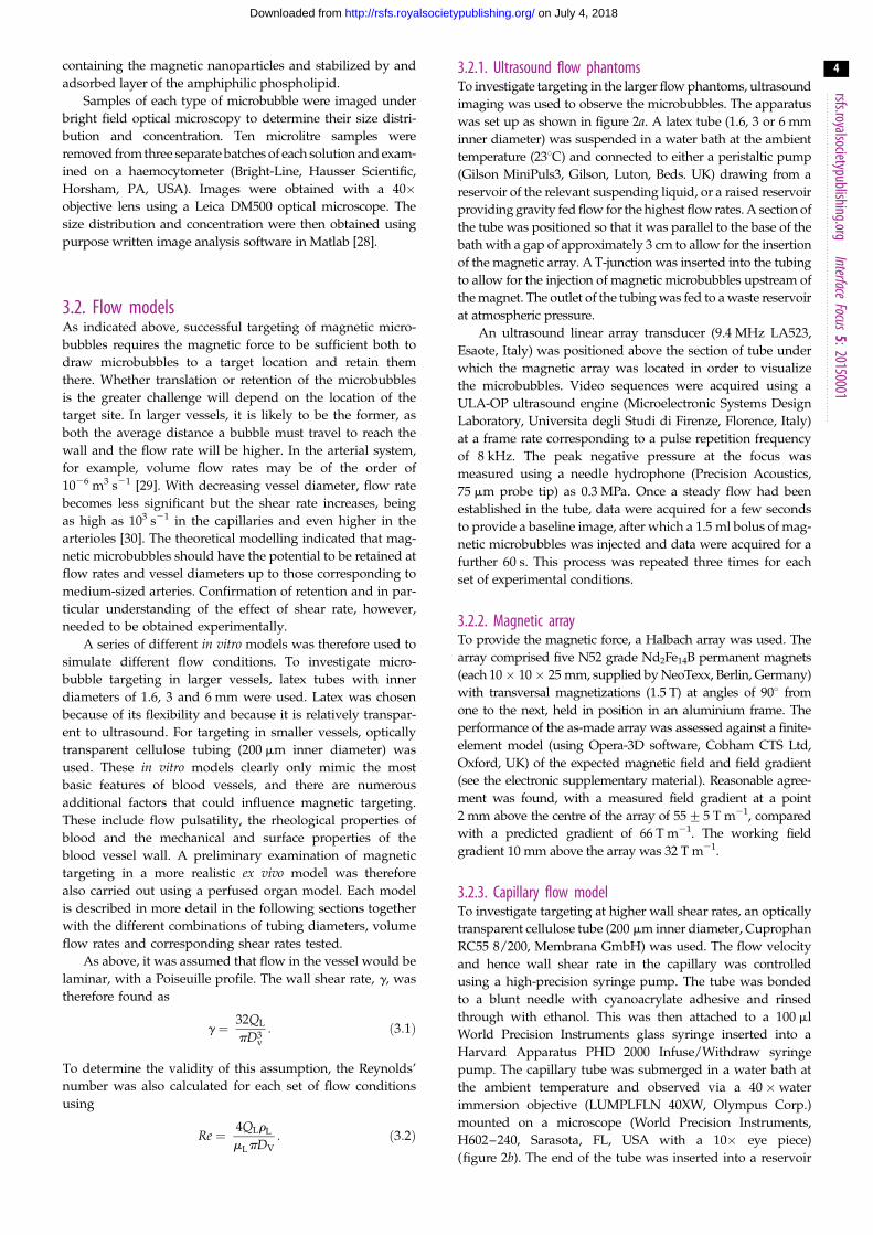
3.2.1. Ultrasound flow phantomsTo investigate targeting in the larger flow phantoms, ultrasound
imaging was used to observe the microbubbles. The apparatus
was set up as shown in figure 2a. A latex tube (1.6, 3 or 6 mm
inner diameter) was suspended in a water bath at the ambient
temperature (238C) and connected to either a peristaltic pump
(Gilson MiniPuls3, Gilson, Luton, Beds. UK) drawing from a
reservoir of the relevant suspending liquid, or a raised reservoir
providing gravity fed flow for the highest flow rates. A section of
the tube was positioned so that it was parallel to the base of the
bath with a gap of approximately 3 cm to allow for the insertion
of the magnetic array. A T-junction was inserted into the tubing
to allow for the injection of magnetic microbubbles upstream of
the magnet. The outlet of the tubing was fed to a waste reservoir
at atmospheric pressure.
An ultrasound linear array transducer (9.4 MHz LA523,
Esaote, Italy) was positioned above the section of tube under
which the magnetic array was located in order to visualize
the microbubbles. Video sequences were acquired using a
ULA-OP ultrasound engine (Microelectronic Systems Design
Laboratory, Universita degli Studi di Firenze, Florence, Italy)
at a frame rate corresponding to a pulse repetition frequency
of 8 kHz. The peak negative pressure at the focus was
measured using a needle hydrophone (Precision Acoustics,
75 mm probe tip) as 0.3 MPa. Once a steady flow had been
established in the tube, data were acquired for a few seconds
to provide a baseline image, after which a 1.5 ml bolus of mag-
netic microbubbles was injected and data were acquired for a
further 60 s. This process was repeated three times for each
set of experimental conditions.
3.2.2. Magnetic arrayTo provide the magnetic force, a Halbach array was used. The
array comprised five N52 grade Nd2Fe14B permanent magnets
(each 10� 10� 25 mm, supplied by NeoTexx, Berlin, Germany)
with transversal magnetizations (1.5 T) at angles of 908 from
one to the next, held in position in an aluminium frame. The
performance of the as-made array was assessed against a finite-
element model (using Opera-3D software, Cobham CTS Ltd,
Oxford, UK) of the expected magnetic field and field gradient
(see the electronic supplementary material). Reasonable agree-
ment was found, with a measured field gradient at a point
2 mm above the centre of the array of 55+5 T m21, compared
with a predicted gradient of 66 T m21. The working field
gradient 10 mm above the array was 32 T m21.
3.2.3. Capillary flow modelTo investigate targeting at higher wall shear rates, an optically
transparent cellulose tube (200 mm inner diameter, Cuprophan
RC55 8/200, Membrana GmbH) was used. The flow velocity
and hence wall shear rate in the capillary was controlled
using a high-precision syringe pump. The tube was bonded
to a blunt needle with cyanoacrylate adhesive and rinsed
through with ethanol. This was then attached to a 100 ml
World Precision Instruments glass syringe inserted into a
Harvard Apparatus PHD 2000 Infuse/Withdraw syringe
pump. The capillary tube was submerged in a water bath at
the ambient temperature and observed via a 40 � water
immersion objective (LUMPLFLN 40XW, Olympus Corp.)
mounted on a microscope (World Precision Instruments,
H602–240, Sarasota, FL, USA with a 10� eye piece)
(figure 2b). The end of the tube was inserted into a reservoir
3D positioningsystem
ultrasoundprobe
syringe with microbubblesolution
3-way valve
direction offlow
watertank
peristalticpump
waterreservoir
waste waterreservoir flow phantom magnet positioning
stage
magnet
CCD camera computer
magnetcapillary tube
200 mm
water tank
not to scale
ULAOP
(a)
(b)
Figure 2. Schematic of flow phantom apparatus used in the experiments for (a) ultrasound imaging and (b) optical microscopy.
rsfs.royalsocietypublishing.orgInterface
Focus5:20150001
5
on July 4, 2018http://rsfs.royalsocietypublishing.org/Downloaded from
filled with 450 ml of the relevant suspending liquid and con-
taining 50 ml of the magnetic microbubble suspension. The
syringe was set to withdraw and liquid was drawn through
the tube at a constant rate that was varied between 1.7 and
8.4 ml s21. A single N52 grade NdFeB permanent magnet
was positioned 1 mm from the tube wall giving a field of
0.37 T and gradient 78.5 T m21 at the wall. Video footage of
the microbubbles was recorded using a digital camera
mounted on the microscope eyepiece (DCU224M, ThorLabs
Ltd). Again the experiment was repeated three times for each
flow rate.
3.2.4. Targeting in bloodThe majority of the experiments were carried out in phosphate-
buffered saline (PBS). In a previous study by the authors,
however, it was shown that microbubble targeting may be
substantially reduced in whole blood compared with PBS [31].
A subset of the experiments, corresponding to the higher
flow and/or shear rates was therefore repeated with the
microbubbles suspended in whole porcine blood. White
Landrace pigs weighing 45–60 kg were used for blood donation
and were treated in accordance with the United Kingdom
Animals (Scientific Procedures) Act 1986. The internal jugular
vein and carotid artery were cannulated following isofluorane
induction of general anaesthesia and endotracheal intuba-
tion. Heparin (20 000 Units; CP Pharmaceuticals, UK) was
administered intravenously, and a GelofusineTM (B Braun,
UK) infusion was commenced via the central venous line.
Autologous donor blood was collected via the aortic cannula
and was stored in dextrose-supplemented citrate blood transfu-
sion bags (CPDA-1 Single Blood Collection Systems; Fenwal,
USA) at 48C for subsequent use.
3.2.5. Perfused liver targetingAn extracorporeal normothermic liver perfusion device, which
was developed for organ preservation prior to transplantation
and which can maintain a liver in a functional state for in excess
of 72 h ex vivo, was used to provide a more physiologically rel-
evant model [32]. A porcine liver was chosen as it is widely
accepted to be the most representative preclinical model [33].
One advantageous feature of the liver perfusion device was
that vascular flow rates could be controlled precisely, or per-
fusion could be stopped entirely by turning the device off
and clamping the inflow/outflow tracts. Details of the retrieval
process and perfusion system may be found in the electronic
supplementary material. Following approximately 30 min of
normothermic machine perfusion, the liver was placed in an
acoustically transparent 50 � 50 cm sterile intestinal bag
(3 M, USA) filled with isotonic colloid solution (Gelofusine,
Braun, UK), which had been degassed and pre-heated to
378C. The bag was suspended in a silicone sling over a water
bath containing an acoustic absorber in the base, which was
continuously degassed and heated to 378C.
A suitable blood vessel was located using a linear array
probe (model L10-5; Zonare Medical Systems, Mountain
View, CA, USA) with 128 elements, 38 mm aperture and
150retention time
inte
nsity
100
flow
magnetic array
regions of interest
(a)
(b)
rsfs.royalsocietypublishing.orgInterface
Focu
6
on July 4, 2018http://rsfs.royalsocietypublishing.org/Downloaded from
5–10 MHz bandwidth attached to an ultrasound engine
(model z.one; Zonare Medical Systems) and the magnetic Hal-
bach array was inserted underneath the liver in as close
proximity to the liver as possible, giving a magnetic field of
0.05 T at the vessel wall. From the theoretical modelling and
in vitro experiments it was clear that this would be insufficient
to retain microbubbles at the normal perfusion rate (approx.
6 ml s21) and the flow rate in the vessel was therefore reduced
(to approx. 0.3 ml s21) by partially clamping the inflow tracts.
The ultrasound probe was held in position with a clamp and
the vessel was cannulated with a 22G hypodermic needle.
A 1.5 ml bolus of the magnetic microbubble suspension was
injected through the needle and data recorded as in the flow
phantom experiments. The experiment was repeated in a
second liver.
difference inchange in intensity
% c
hang
e in
reg
ion
50
0
–500 2000 4000 6000 8000
frame no.
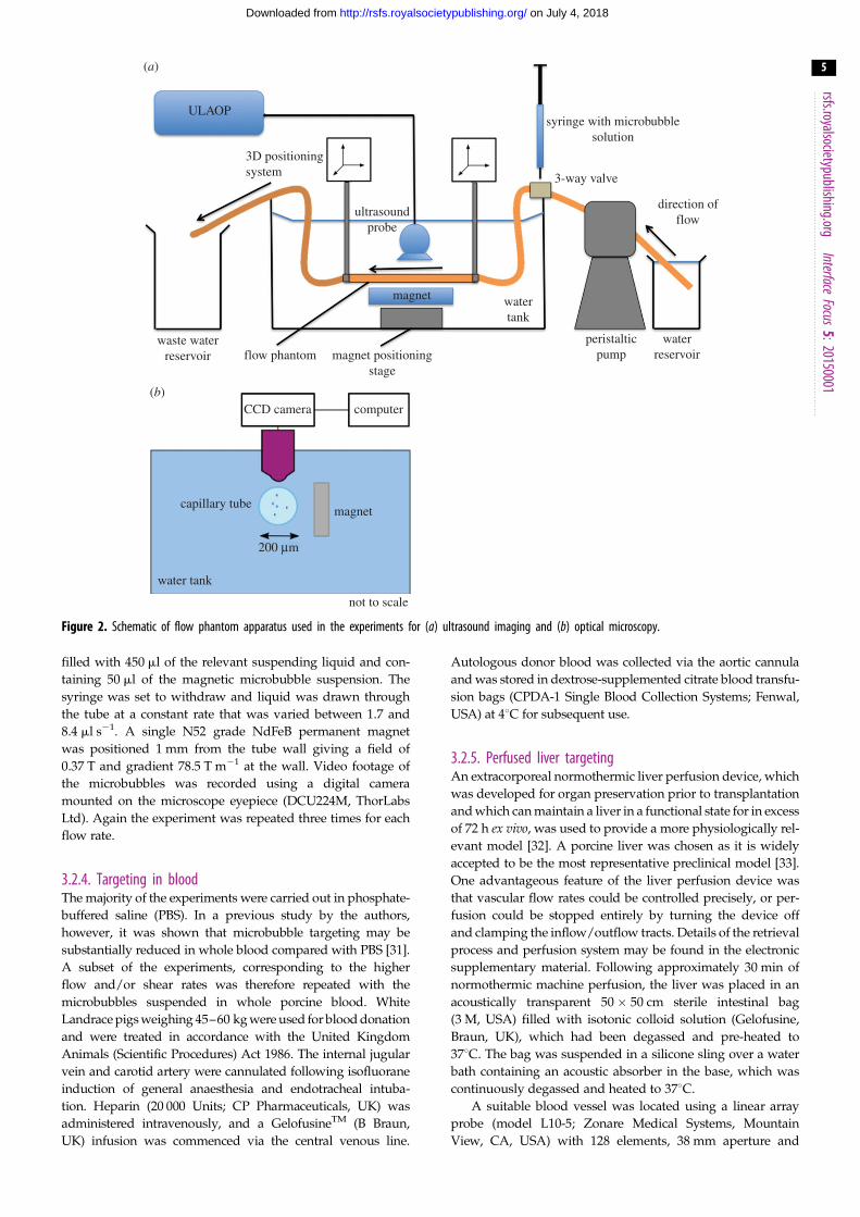
Figure 3. (a) Example of image obtained in ultrasound flow phantom show-ing regions of interest at the upper and lower surfaces of the tube and(b) example of graph showing change in intensity within both regions ofinterest (microbubbles arrive at the section of the tube under the ultrasoundprobe after approx. 2000 frames).
s5:20150001
3.3. Image processing3.3.1. Ultrasound imagingPrevious studies have demonstrated that ultrasound image
intensity is directly proportional to microbubble concentration
for clinically relevant values (104–105 microbubbles ml21) [34].
As far as possible, the size distribution, concentration and
volume of the microbubble suspensions were kept constant
throughout the study. Therefore, it was deemed reasonable
to assume that image intensity would provide an indication
of the quantity of microbubbles retained in these experiments.
It is likely that the microbubble concentrations produced by
magnetic targeting actually exceeded the limiting value for a
linear relationship between image intensity and concentration
[35]. This would have led to an underestimate in the number
retained. As, however, it was the relative change in intensity
that was of interest for each set of experimental conditions
the resulting uncertainty was considered to be acceptable.
A purpose-written Matlab program was used to quantify
the retention of the microbubbles by the magnet. Two rec-
tangular regions of interest were defined at the lower and
upper surfaces of the tube (figure 3a). If microbubbles are suc-
cessfully retained, then the intensity of the former should
increase over time while that of the latter should remain the
same. The change in intensity over the course of each exper-
iment was measured and plotted as shown in figure 3b.
The average steady-state change in intensity was determined
for each set of conditions. For drug delivery to occur, magnetic
microbubbles must be retained both in sufficient concentration
and for a sufficient length of time for therapeutic effects to
be realized. Therefore, the time over which the increase in
intensity was sustained was also determined.
3.3.2. Optical imagingThe number of microbubbles retained in the capillary tube at
each flow rate over a period of 4 min was determined, again
using a purpose-written Matlab program. In practice (see §4.3),
the number of magnetic microbubbles retained was such that
individual bubbles could not be discerned. Therefore, the
width of the retained microbubble bolus was measured from
the images. This method of quantification will inevitably
produce an underestimate of the number of targeted micro-
bubbles as the image analysis was only performed in the focal
plane. However, all measurements were relative and the
focal plane was maintained between the experiments.
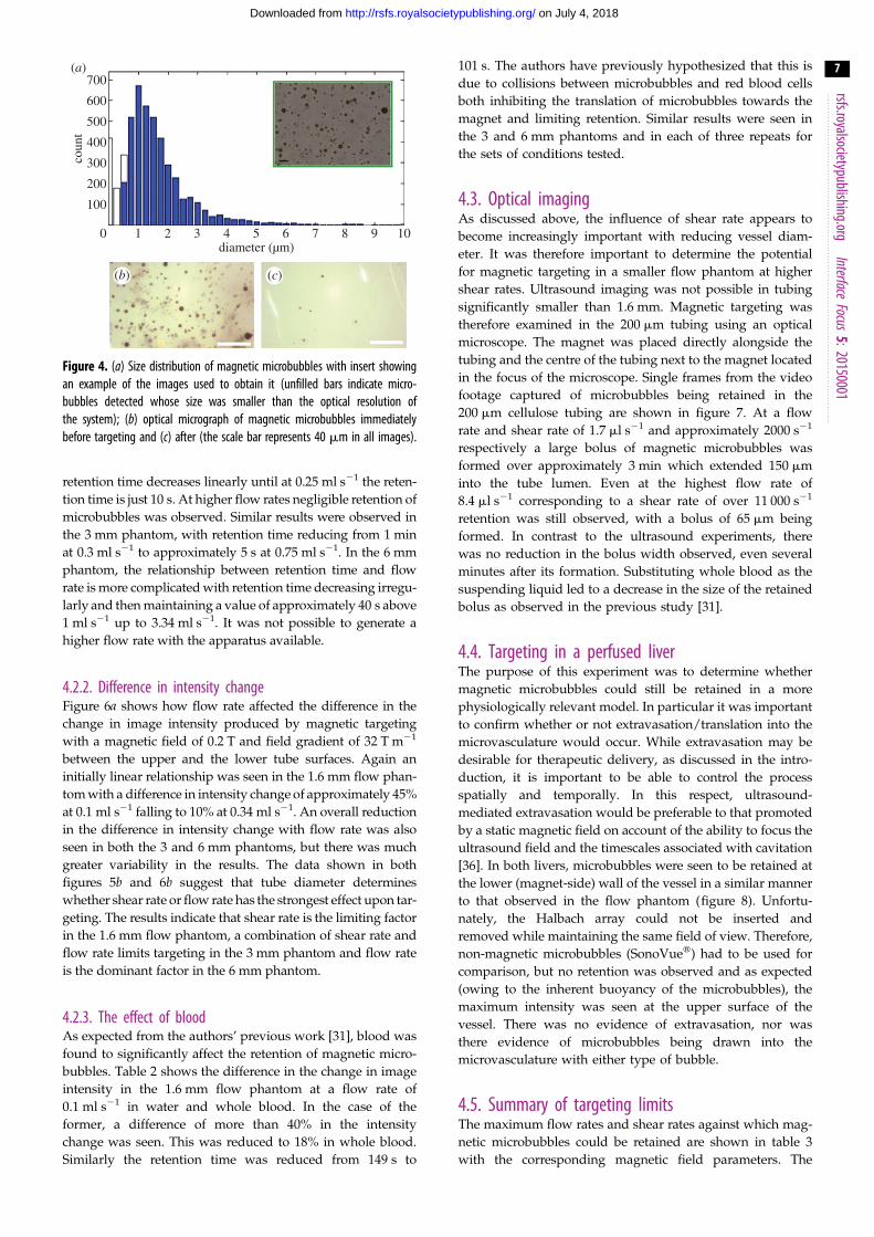
4. Results4.1. Microbubble size distribution and concentrationFigure 4a shows the average size distribution and concentration
of the magnetic microbubbles obtained from the microscope
images immediately following preparation. The modal diam-
eter was between 1 and 2 mm and the mean concentration
was approximately 107 microbubbles ml21. Measurements
were performed before each set of experiments that confirmed
consistency between the different batches.
It was important to determine whether or not magnetic tar-
geting led to agglomeration of microbubbles, as the formation
of large bubbles could potentially pose a risk of embolism. This
was investigated by examining magnetic microbubbles before
and after retention with the magnet in the capillary tube
(figure 4b). Following removal of the magnet, the bolus of
microbubbles was seen to disperse and the size distribution
and appearance of the microbubbles were found to be indistin-
guishable from those before retention. No large bubbles were
observed in any of the 30 images taken post retention.
4.2. Ultrasound imagingIn the results presented below, the intensity in each region of
interest is expressed as a percentage of its initial value to mini-
mize the effect of any differences in image background
intensity. ‘Retention time’ refers to the time for which the
change in image intensity at the lower tube surface (nearest
the magnet) is elevated above that of the upper by at least 5%
(figure 3). The magnitude of this difference was also recorded.
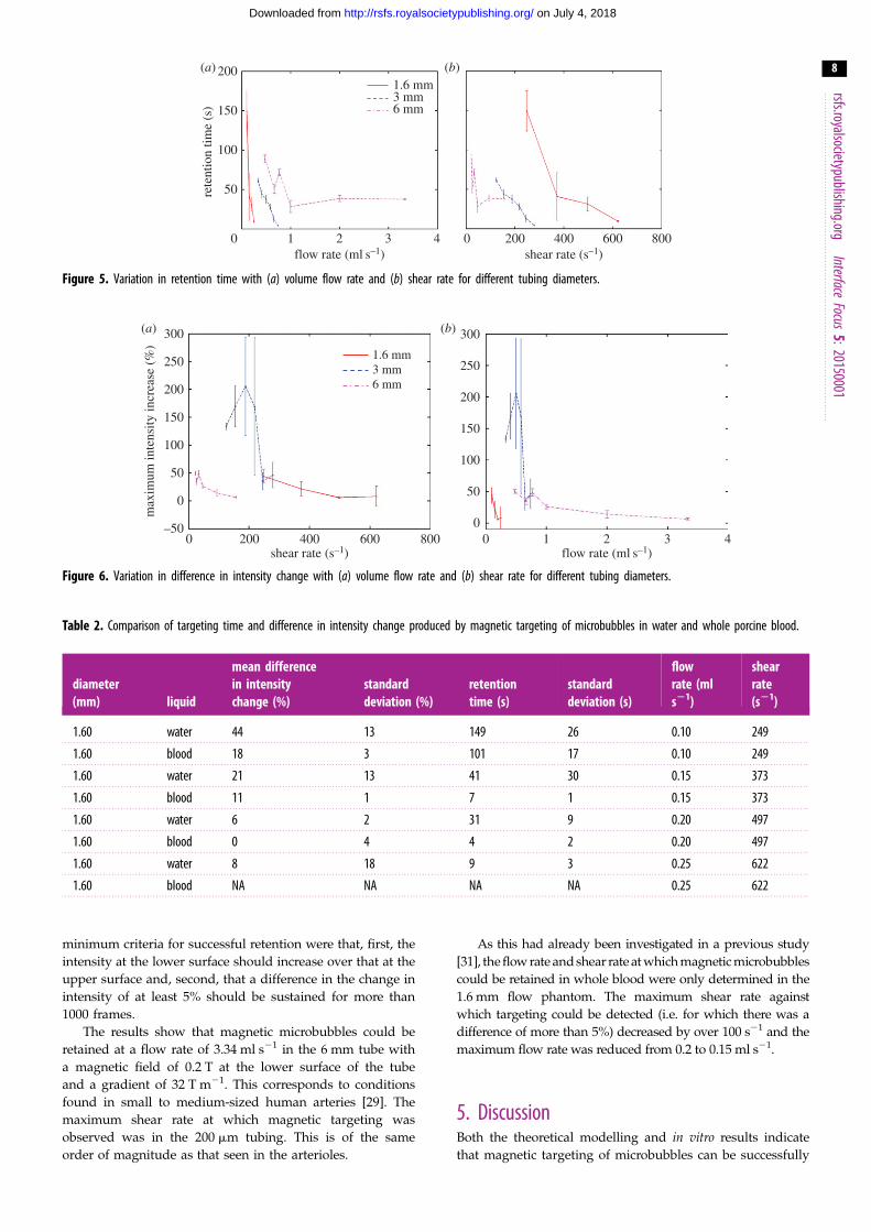
4.2.1. Retention timeFigure 5a shows the variation in retention time with flow rate
for a magnetic field along the bottom of the tube of 0.2 T. In
the 1.6 mm flow phantom, as the flow rate increases the
700
600
500
400
300
200
100
0 1 2 3 4 5 6 7 8 9 10diameter (µm)
coun
t(a)
(b) (c)
Figure 4. (a) Size distribution of magnetic microbubbles with insert showingan example of the images used to obtain it (unfilled bars indicate micro-bubbles detected whose size was smaller than the optical resolution ofthe system); (b) optical micrograph of magnetic microbubbles immediatelybefore targeting and (c) after (the scale bar represents 40 mm in all images).
rsfs.royalsocietypublishing.orgInterface
Focus5:20150001
7
on July 4, 2018http://rsfs.royalsocietypublishing.org/Downloaded from
retention time decreases linearly until at 0.25 ml s21 the reten-
tion time is just 10 s. At higher flow rates negligible retention of
microbubbles was observed. Similar results were observed in
the 3 mm phantom, with retention time reducing from 1 min
at 0.3 ml s21 to approximately 5 s at 0.75 ml s21. In the 6 mm
phantom, the relationship between retention time and flow
rate is more complicated with retention time decreasing irregu-
larly and then maintaining a value of approximately 40 s above
1 ml s21 up to 3.34 ml s21. It was not possible to generate a
higher flow rate with the apparatus available.
4.2.2. Difference in intensity changeFigure 6a shows how flow rate affected the difference in the
change in image intensity produced by magnetic targeting
with a magnetic field of 0.2 T and field gradient of 32 T m21
between the upper and the lower tube surfaces. Again an
initially linear relationship was seen in the 1.6 mm flow phan-
tom with a difference in intensity change of approximately 45%
at 0.1 ml s21 falling to 10% at 0.34 ml s21. An overall reduction
in the difference in intensity change with flow rate was also
seen in both the 3 and 6 mm phantoms, but there was much
greater variability in the results. The data shown in both
figures 5b and 6b suggest that tube diameter determines
whether shear rate or flow rate has the strongest effect upon tar-
geting. The results indicate that shear rate is the limiting factor
in the 1.6 mm flow phantom, a combination of shear rate and
flow rate limits targeting in the 3 mm phantom and flow rate
is the dominant factor in the 6 mm phantom.
4.2.3. The effect of bloodAs expected from the authors’ previous work [31], blood was
found to significantly affect the retention of magnetic micro-
bubbles. Table 2 shows the difference in the change in image
intensity in the 1.6 mm flow phantom at a flow rate of
0.1 ml s21 in water and whole blood. In the case of the
former, a difference of more than 40% in the intensity
change was seen. This was reduced to 18% in whole blood.
Similarly the retention time was reduced from 149 s to
101 s. The authors have previously hypothesized that this is
due to collisions between microbubbles and red blood cells
both inhibiting the translation of microbubbles towards the
magnet and limiting retention. Similar results were seen in
the 3 and 6 mm phantoms and in each of three repeats for
the sets of conditions tested.
4.3. Optical imagingAs discussed above, the influence of shear rate appears to
become increasingly important with reducing vessel diam-
eter. It was therefore important to determine the potential
for magnetic targeting in a smaller flow phantom at higher
shear rates. Ultrasound imaging was not possible in tubing
significantly smaller than 1.6 mm. Magnetic targeting was
therefore examined in the 200 mm tubing using an optical
microscope. The magnet was placed directly alongside the
tubing and the centre of the tubing next to the magnet located
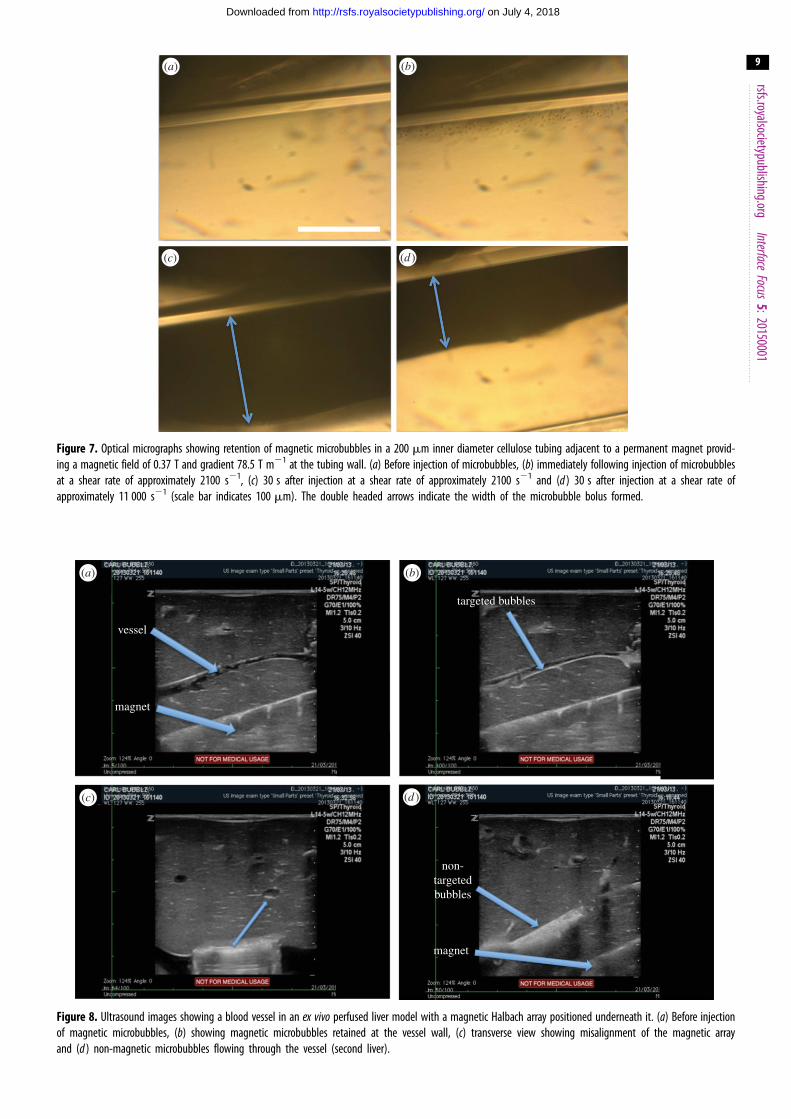
in the focus of the microscope. Single frames from the video
footage captured of microbubbles being retained in the
200 mm cellulose tubing are shown in figure 7. At a flow
rate and shear rate of 1.7 ml s21 and approximately 2000 s21
respectively a large bolus of magnetic microbubbles was
formed over approximately 3 min which extended 150 mm
into the tube lumen. Even at the highest flow rate of
8.4 ml s21 corresponding to a shear rate of over 11 000 s21
retention was still observed, with a bolus of 65 mm being
formed. In contrast to the ultrasound experiments, there
was no reduction in the bolus width observed, even several
minutes after its formation. Substituting whole blood as the
suspending liquid led to a decrease in the size of the retained
bolus as observed in the previous study [31].
4.4. Targeting in a perfused liverThe purpose of this experiment was to determine whether
magnetic microbubbles could still be retained in a more
physiologically relevant model. In particular it was important
to confirm whether or not extravasation/translation into the
microvasculature would occur. While extravasation may be
desirable for therapeutic delivery, as discussed in the intro-
duction, it is important to be able to control the process
spatially and temporally. In this respect, ultrasound-
mediated extravasation would be preferable to that promoted
by a static magnetic field on account of the ability to focus the
ultrasound field and the timescales associated with cavitation
[36]. In both livers, microbubbles were seen to be retained at
the lower (magnet-side) wall of the vessel in a similar manner
to that observed in the flow phantom (figure 8). Unfortu-
nately, the Halbach array could not be inserted and
removed while maintaining the same field of view. Therefore,
non-magnetic microbubbles (SonoVuew) had to be used for
comparison, but no retention was observed and as expected
(owing to the inherent buoyancy of the microbubbles), the
maximum intensity was seen at the upper surface of the
vessel. There was no evidence of extravasation, nor was
there evidence of microbubbles being drawn into the
microvasculature with either type of bubble.
4.5. Summary of targeting limitsThe maximum flow rates and shear rates against which mag-
netic microbubbles could be retained are shown in table 3
with the corresponding magnetic field parameters. The
1.6 mm 3 mm 6 mm
rete
ntio
n tim
e (s
)
200
150
100
50
0 1 2 3 4flow rate (ml s–1) shear rate (s–1)
0 200 400 600 800
(a) (b)
Figure 5. Variation in retention time with (a) volume flow rate and (b) shear rate for different tubing diameters.
1.6 mm 3 mm 6 mm
300
250
200
150
100
50
0
–50
300
250
200
150
100
50
00 1 2 3 40 200 400 600 800
shear rate (s–1)
max
imum
inte
nsity
incr
ease
(%
)
flow rate (ml s–1)
(a) (b)
Figure 6. Variation in difference in intensity change with (a) volume flow rate and (b) shear rate for different tubing diameters.
Table 2. Comparison of targeting time and difference in intensity change produced by magnetic targeting of microbubbles in water and whole porcine blood.
diameter(mm) liquid
mean differencein intensitychange (%)
standarddeviation (%)
retentiontime (s)
standarddeviation (s)
flowrate (mls21)
shearrate(s21)
1.60 water 44 13 149 26 0.10 249
1.60 blood 18 3 101 17 0.10 249
1.60 water 21 13 41 30 0.15 373
1.60 blood 11 1 7 1 0.15 373
1.60 water 6 2 31 9 0.20 497
1.60 blood 0 4 4 2 0.20 497
1.60 water 8 18 9 3 0.25 622
1.60 blood NA NA NA NA 0.25 622
rsfs.royalsocietypublishing.orgInterface
Focus5:20150001
8
on July 4, 2018http://rsfs.royalsocietypublishing.org/Downloaded from
minimum criteria for successful retention were that, first, the
intensity at the lower surface should increase over that at the
upper surface and, second, that a difference in the change in
intensity of at least 5% should be sustained for more than
1000 frames.
The results show that magnetic microbubbles could be
retained at a flow rate of 3.34 ml s21 in the 6 mm tube with
a magnetic field of 0.2 T at the lower surface of the tube
and a gradient of 32 T m21. This corresponds to conditions
found in small to medium-sized human arteries [29]. The
maximum shear rate at which magnetic targeting was
observed was in the 200 mm tubing. This is of the same
order of magnitude as that seen in the arterioles.
As this had already been investigated in a previous study
[31], the flow rate and shear rate at which magnetic microbubbles
could be retained in whole blood were only determined in the
1.6 mm flow phantom. The maximum shear rate against
which targeting could be detected (i.e. for which there was a
difference of more than 5%) decreased by over 100 s21 and the
maximum flow rate was reduced from 0.2 to 0.15 ml s21.
5. DiscussionBoth the theoretical modelling and in vitro results indicate
that magnetic targeting of microbubbles can be successfully
(b)(a)
(c) (d )
Figure 7. Optical micrographs showing retention of magnetic microbubbles in a 200 mm inner diameter cellulose tubing adjacent to a permanent magnet provid-ing a magnetic field of 0.37 T and gradient 78.5 T m21 at the tubing wall. (a) Before injection of microbubbles, (b) immediately following injection of microbubblesat a shear rate of approximately 2100 s21, (c) 30 s after injection at a shear rate of approximately 2100 s21 and (d ) 30 s after injection at a shear rate ofapproximately 11 000 s21 (scale bar indicates 100 mm). The double headed arrows indicate the width of the microbubble bolus formed.
vessel
targeted bubbles
non-targetedbubbles
magnet
magnet
(b)(a)
(c) (d )
Figure 8. Ultrasound images showing a blood vessel in an ex vivo perfused liver model with a magnetic Halbach array positioned underneath it. (a) Before injectionof magnetic microbubbles, (b) showing magnetic microbubbles retained at the vessel wall, (c) transverse view showing misalignment of the magnetic arrayand (d ) non-magnetic microbubbles flowing through the vessel (second liver).
rsfs.royalsocietypublishing.orgInterface
Focus5:20150001
9
on July 4, 2018http://rsfs.royalsocietypublishing.org/Downloaded from
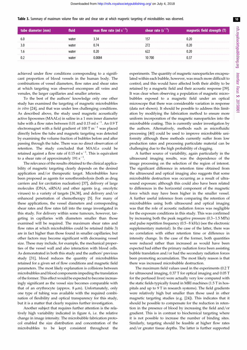
Table 3. Summary of maximum volume flow rate and shear rate at which magnetic targeting of microbubbles was observed.
tube diameter (mm) fluid max flow rate (ml s21) shear rate (s21) magnetic field strength (T)
6.0 water 3.34 157 0.20
3.0 water 0.74 272 0.20
1.6 water 0.20 622 0.20
0.2 water 0.0084 10 700 0.37
rsfs.royalsocietypublishing.orgInterface
Focus5:20150001
10
on July 4, 2018http://rsfs.royalsocietypublishing.org/Downloaded from
achieved under flow conditions corresponding to a signifi-
cant proportion of blood vessels in the human body. The
combinations of vessel diameters, flow rates and shear rates
at which targeting was observed encompass all veins and
venules, the larger capillaries and smaller arteries.
To the best of the authors’ knowledge only one other
study has examined the targeting of magnetic microbubbles
in vitro [24], and that was under less challenging conditions.
As described above, the study used magnetic acoustically
active liposomes (MAALs) in saline in a 1 mm inner diameter
tube with a flow rates between 0.01 and 0.15 ml s21. An 0.9 T
electromagnet with a field gradient of 100 T m21 was placed
directly below the tube and magnetic targeting was detected
by examining the volume fraction of bubbles before and after
passing through the tube. There was no direct observation of
retention. The study concluded that MAALs could be
retained against a flow rate of 0.15 ml s21. This is equivalent
to a shear rate of approximately 191 s21.
The relevance of the results obtained to the clinical applica-
bility of magnetic targeting clearly depends on the desired
application and/or therapeutic target. Microbubbles have
been proposed as agents for sonothrombolysis (both as drug
carriers and for cavitation nucleation) [37], delivery of large
molecules (DNA, siRNA) and other agents (e.g. oncolytic
viruses) to a variety of targets [36,38], and delivery and/or
enhanced penetration of chemotherapy [5]. For many of
these applications, the vessel diameters and corresponding
shear rates and flow rates fall into the range investigated in
this study. For delivery within some tumours, however, tar-
geting in capillaries with diameters smaller than those
examined will be required. The maximum shear rates and
flow rates at which microbubbles could be retained (table 3)
are in fact higher than those found in smaller capillaries; but
other factors may become significant with decreasing vessel
size. These may include, for example, the mechanical proper-
ties of the vessel wall and also interaction with blood cells.
As demonstrated in both this study and the authors’ previous
study [31], blood reduces the quantity of microbubbles
retained for a given set of flow conditions and magnetic field
parameters. The most likely explanation is collisions between
microbubbles and blood components impeding the translation
of the former. This effect would be expected to become increas-
ingly significant as the vessel size becomes comparable with
that of an erythrocyte (approx. 8 mm). Unfortunately, only
one type of tubing was available with the required combi-
nation of flexibility and optical transparency for this study,
but it is a matter that clearly requires further investigation.
Another subject that requires further attention is the rela-
tively high variability indicated in figure 6, i.e. the relative
change in image intensity. The microbubble fabrication proto-
col enabled the size distribution and concentration of the
microbubbles to be kept consistent throughout the
experiments. The quantity of magnetic nanoparticles encapsu-
lated within each bubble, however, was much more difficult to
control; and this would have affected both their ability to be
retained by a magnetic field and their acoustic response [39].
It was clear when observing a population of magnetic micro-
bubbles exposed to a magnetic field under an optical
microscope that there was considerable variation in response
(data not shown). It should be possible to address this limit-
ation by modifying the fabrication method to ensure more
uniform incorporation of the magnetic nanoparticles into the
microbubble coating. This is currently under investigation by
the authors. Alternatively, methods such as microfluidic
processing [40] could be used to improve microbubble uni-
formity although these methods currently suffer from low
production rates and processing particulate material can be
challenging due to the high probability of clogging.
A further source of variability, again particularly in the
ultrasound imaging results, was the dependence of the
image processing on the selection of the region of interest.
The significant difference in retention time obtained from
the ultrasound and optical imaging also suggests that some
microbubble destruction was occurring as a result of ultra-
sound exposure; although this could also have been related
to differences in the horizontal component of the magnetic
force which may have been higher in the smaller vessel.
A further useful inference from comparing the retention of
microbubbles using both ultrasound and optical imaging
was that the role of acoustic radiation forces was negligible
for the exposure conditions in this study. This was confirmed
by increasing both the peak negative pressure (0.3–1.5 MPa)
and pulse repetition frequency (0.5–8 kHz) (see the electronic
supplementary material). In the case of the latter, there was
no correlation with either retention time or difference in
intensity change. In the case of the former, both quantities
were reduced rather than increased as would have been
expected had either the primary radiation force been assisting
bubble translation and/or had the secondary radiation forces
been promoting accumulation. The most likely reason is that
there was increased microbubble destruction.
The maximum field values used in the experiments (0.2 T
for ultrasound imaging, 0.37 T for optical imaging and 0.05 T
for the perfused liver) were actually very low compared with
the static fields typically found in MRI machines (1.5 T in hos-
pitals and up to 9 T in research systems). The field gradients
were relatively high but smaller than those used in other
magnetic targeting studies (e.g. [24]). This indicates that it
should be possible to compensate for the reduction in reten-
tion in the presence of blood by increasing the field and/or
gradient. This is in contrast to biochemical targeting where
it is not possible to increase the number of binding sites.
Similarly, targeting should be feasible at higher flow rates
and/or greater tissue depths. The latter is further supported
rsfs.royalsocietypublishing.orgInterface
Focus5:20150001
11
on July 4, 2018http://rsfs.royalsocietypublishing.org/Downloaded from
by studies of other magnetically responsive microparticles [17].
In terms of safety, the magnetic nanoparticles used are similar
to those currently used as MRI contrast agents and whose tox-
icity profile and clearance mechanisms are relatively well
understood. The potential for additional risk due to magnetic
actuation has also been examined previously and the existing
evidence would indicate this is very small [41].
The experiments in the perfused liver highlighted the
importance of correctly aligning the magnetic array with
respect to the target vessel. Rotation of the ultrasound
probe demonstrated that the orientation of the array was
such that the magnetic force was not maximized at the wall
of the vessel. This could be addressed by substitution of the
basic Halbach array for a three-dimensional (3D) configur-
ation and integration between the array and the ultrasound
probe. Although there was no evidence of extravasation,
the use of multiple magnets to achieve 3D manipulation of
the microbubbles would be advantageous in avoiding
unwanted transport of the bubbles, e.g. from large vessels
into the microvasculature.
6. ConclusionThe results of this study indicate that magnetic targeting of
microbubbles can be achieved under flow conditions relevant
to human physiology using magnetic fields that are safe for
clinical use. With a maximum field of 0.2 T and gradient of
32 T m21, microbubbles were successfully retained in vessel
phantoms with diameters ranging from 200 mm to 6 mm
and at combinations of shear rates and flow rates
corresponding to the larger capillaries, all veins and venules
and small arteries. When the microbubbles were suspended
in whole blood rather than saline, the quantity of micro-
bubbles retained at a given combination of vessel diameter,
flow rate and shear rate was reduced. Larger magnetic
fields and field gradients and/or more magnetically respon-
sive microbubble formulations will therefore be required to
compensate for this effect; but this should not present a sig-
nificant challenge given the field parameters used in
existing MRI systems. Retention of microbubbles was also
demonstrated in an ex vivo perfused porcine liver model,
with the additional beneficial features that there was no evi-
dence of any microbubble extravasation out of the blood
vessels, nor was any agglomeration observed—both of
which are important safety considerations when it comes to
the translation of this technology into clinical use.
Ethics. All animal studies were conducted in accordance with theUnited Kingdom Animals (Scientific Procedures) Act 1986 andlocal ethical approval was obtained.
Data accessibility. All data and methods are reported within this paper,the electronic supplementary material and at doi:10.5072/bodleian:xp68kj24v.
Competing interests. We declare we have no competing interests.
Funding. We thank the Engineering and Physical Sciences ResearchCouncil for supporting the work through EP/I021795/1.
Acknowledgements. The authors thank Mr James Fisk and Mr DavidSalisbury of the Oxford IBME workshop for their assistance in con-structing the experimental apparatus and Dr Carl Jensen and DrEleonora Mylonopoulou for their assistance with the perfused liverexperiments.
References
1. Harrison C. 2011 The patent cliff steepens. Nat. Rev.Drug Discov. 10, 12 – 13. (doi:10.1038/nrd3356)
2. Langer R. 1998 Drug delivery and targeting. Nature392, 5 – 10.
3. Lipinski C. 2002 Poor aqueous solubility—anindustry wide problem in drug discovery. Am.Pharm. Rev. 5, 82 – 85.
4. Yang YY, Chung TS, Ng NP. 2001 Morphology, drugdistribution, and in vitro release profiles ofbiodegradable polymeric microspheres containingprotein fabricated by double-emulsion solventextraction/evaporation method. Biomaterials 22,231 – 241. (doi:10.1016/S0142-9612(00)00178-2)
5. Ferrara K, Pollard R, Borden M. 2007 Ultrasoundmicrobubble contrast agents: fundamentals andapplication to gene and drug delivery. Annu. Rev.Biomed. Eng. 9, 415 – 447. (doi:10.1146/annurev.bioeng.8.061505.095852)
6. Unger EC, Hersh E, Vannan M, Matsunaga TO,McCreery M. 2001 Local drug and gene deliverythrough microbubbles. Prog. Cardiovasc. Dis. 44,45 – 54. (doi:10.1053/pcad.2001.26443)
7. Harvey CJ, Pilcher JM, Eckersley RJ, Blomley MJK,Cosgrove DO. 2002 Advances in ultrasound. Clin.Radiol. 57, 157 – 177. (doi:10.1053/crad.2001.0918)
8. Lentacker I, De Cock I, Deckers R, De Smedt SC,Moonen CT. 2014 Understanding ultrasound induced
sonoporation: definitions and underlyingmechanisms. Adv. Drug Deliv. Rev. 72, 49 – 64.(doi:10.1016/j.addr.2013.11.008)
9. Mo S, Coussios CC, Seymour L, Carlisle R. 2012Ultrasound-enhanced drug delivery for cancer.Expert Opin. Drug Deliv. 9, 1525 – 1538. (doi:10.1517/17425247.2012.739603)
10. Jackson JK, Pirmoradi FN, Wan CP, Siu T, Chiao M, BurtHM. 2011 Increased accumulation of paclitaxel anddoxorubicin in proliferating capillary cells and prostatecancer cells following ultrasound exposure. Ultrasonics51, 932 – 939. (doi:10.1016/j.ultras.2011.05.008)
11. Tang MX, Mulvana H, Gauthier T, Lim AK, CosgroveDO, Eckersley RJ, Stride E. 2011 Quantitativecontrast-enhanced ultrasound imaging: a review ofsources of variability. Interface Focus 1, 520 – 539.(doi:10.1098/rsfs.2011.0026)
12. Villanueva FS, Jankowski RJ, Manaugh C, Wagner WR.1997 Albumin microbubble adherence to humancoronary endothelium: implications for assessment ofendothelial function using myocardial contrastechocardiography. J. Am. Coll. Cardiol. 30, 689 – 693.(doi:10.1016/S0735-1097(97) 00197-6)
13. Martin MJ, Chung EML, Goodall AH, Martina AD,Ramnarine KV, Fan L, Hainsworth SV, Naylor AR,Evans DH. 2007 Enhanced detection ofthromboemboli with the use of targeted
microbubbles. Stroke 38, 2726 – 2732. (doi:10.1161/STROKEAHA.107.489435)
14. Zhao S, Borden M, Bloch SH, Kruse DE, Ferrara KW,Dayton PA. 2004 Increasing binding efficiency ofultrasound targeted agents with radiation force.Proc. IEEE Ultrasonics Symp. 2, 1114 – 1117. (doi:10.1109/ULTSYM.2004.1417975)
15. Arruebo M, Fernandez-Pacheco R, Ibarra MR,Santamaria J. 2007 Magnetic nanoparticles for drugdelivery. Nano Today 2, 22 – 32. (doi:10.1016/S1748-0132(07)70084-1)
16. Zimmerman U, Scheurich P, Pilwat G, Benz R. 1981Cells with manipulated functions: new perspectivesfor cell biology, medicine, and technology. Angew.Chem. Int. Ed. Engl. 20, 325 – 344. (doi:10.1002/anie.198103251)
17. Senyei AE, Reich SD, Gonczy C, Widder KJ. 1981In vivo kinetics of magnetically targeted low-dosedoxorubicin. J. Pharm. Sci. 70, 389 – 391. (doi:10.1002/jps.2600700412)
18. Widder KJ, Senyei AE, Ranney DF. 1980 In vitrorelease of biologically active adriamycin bymagnetically responsive albumin microspheres.Cancer Res. 40, 3512 – 3517.
19. Scherer F, Anton M, Schillinger U, Henke J,Bergemann C, Kruger A, Gansbacher B, Plank C.2002 Magnetofection: enhancing and targeting
rsfs.royalsocietypublishing.orgInterface
Focus5:20150001
12
on July 4, 2018http://rsfs.royalsocietypublishing.org/Downloaded from
gene delivery by magnetic force in vitro and in vivo.Gene Ther. 9, 102 – 109. (doi:10.1038/sj.gt.3301624)
20. Soetanto K, Watarai H. 2000 Development ofmagnetic microbubbles for drug delivery system(dds). Jpn. J. Appl. Phys. 39, 3230 – 3232. (doi:10.1143/JJAP.39.3230)
21. Soetanto K, Watarai H. 2003 Ferromagneticultrasound microbubbles contrast agent. Proc. IEEEEng. Med. Biol. Soc. 2, 1226 – 1229. (doi:10.1109/iembs.2003.1279473)
22. Yang F, Li L, Li Y, Chen Z, Wu J, Gu N. 2008Superparamagnetic nanoparticle-inclusionmicrobubbles for ultrasound contrast agents. Phys.Med. Biol. 53, 6129 – 6141. (doi:10.1088/0031-9155/53/21/016)
23. Yang F, Li Y, Chen Z, Zhang Y, Wu J, Gu N. 2009Superparamagnetic iron oxide nanoparticle-embedded encapsulated microbubbles as dualcontrast agents of magnetic resonance andultrasound imaging. Biomaterials 30, 3882 – 3890.(doi:10.1016/j.biomaterials.2009.03.051)
24. Vlaskou D et al. 2010 Magnetic and acousticallyactive lipospheres for magnetically targeted nucleicacid delivery. Adv. Funct. Mater. 20, 3881 – 3894.(doi:10.1002/adfm.200902388)
25. Vlaskou D, Pradhan P, Bergemann C, Klibanov AL,Hensel K, Schmitz G, Plank C, Mykhaylyk O.2010 Magnetic microbubbles: magneticallytargeted and ultrasound-triggered vectors forgene delivery in vitro. Proc. AIP Int. Conf. Sci.Clin. Appl. Magnetic Carriers 1311, 485. (doi:10.1063/1.3530059)
26. Stride E, Porter C, Prieto AG, Pankhurst Q. 2009Enhancement of microbubble mediated genedelivery by simultaneous exposure to ultrasonic andmagnetic fields. Ultrasound Med. Biol. 35, 861 –868. (doi:10.1016/j.ultrasmedbio.2008.11.010)
27. Mulvana H, Eckersley RJ, Browning R, Hajnal JV,Stride E, Barrack T, Tang M, Pankhurst Q, Wells D.2010 Enhanced gene transfection in vivo usingmagnetic localisation of ultrasound contrast agents:preliminary results. Proc. IEEE Ultrasonics Symp. 1,670 – 673. (doi:10.1109/ULTSYM.2010.5935952)
28. Sennoga CA, Mahue V, Loughran J, Casey J, SeddonJM, Tang MX, Eckersley RJ. 2010 On sizing andcounting of microbubbles using optical microscopy.Ultrasound Med. Biol. 36, 2093 – 2096. (doi:10.1016/j.ultrasmedbio.2010.09.004)
29. Whitmore RL. 1967 The flow behaviour of blood inthe circulation. Nature 215, 123 – 126. (doi:10.1038/215123a0)
30. Reneman RS, Arts T, Hoeks AP. 2006 Wall shearstress—an important determinant of endothelialcell function and structure—in the arterial systemin vivo: discrepancies with theory. J. Vasc. Res. 43,251 – 269. (doi:10.1159/000091648)
31. Owen J, Grove P, Rademeyer P, Stride E. 2014 Theinfluence of blood on targeted microbubbles. J. R. Soc.Interface 11, 20140622. (doi:10.1098/rsif.2014.0622)
32. Butler AJ, Rees MA, Wight DG, Casey ND, AlexanderG, White DJ, Friend PJ. 2002 Successfulextracorporeal porcine liver perfusion for 72 hr.Transplantation 73, 1212 – 1218. (doi:10.1097/00007890-200204270-00005)
33. Court FG, Wemyss-Holden SA, Morrison CP, TeagueBD, Laws PE, Kew J, Dennison AR, Maddern GJ.2003 Segmental nature of the porcine liver and itspotential as a model for experimental partialhepatectomy. Br. J. Surg. 90, 440 – 444.
34. Gorce JM, Arditi M, Schneider M. 2000 Influence ofbubble size distribution on the echogenicity ofultrasound contrast agents—a study of sonovue(tm). Invest. Radiol. 35, 661 – 671. (doi:10.1097/00004424-200011000-00003)
35. Stride E, Saffari N. 2005 Investigating thesignificance of multiple scattering in ultrasoundcontrast agent particle populations. IEEE Trans.Ultrason. Ferroelectr Freq Control 52, 2332 – 2345.(doi:10.1109/TUFFC.2005.1563278)
36. Bazan-Peregrino M, Rifai B, Carlisle RC, Choi J,Arvanitis CD, Seymour LW, Coussios CC. 2013Cavitation-enhanced delivery of a replicatingoncolytic adenovirus to tumors using focusedultrasound. J. Control. Release 169, 40 – 47. (doi:10.1016/j.jconrel.2013.03.017)
37. de Saint Victor M, Crake C, Coussios CC, Stride E.2014 Properties, characteristics and applications ofmicrobubbles for sonothrombolysis. Expert Opin.Drug Deliv. 11, 187 – 209. (doi:10.1517/17425247.2014.868434)
38. Carson AR, McTiernan CF, Lavery L, Grata M, Leng X,Wang J, Chen X, Villanueva FS. 2012 Ultrasound-targeted microbubble destruction to deliver sirnacancer therapy. Cancer Res. 72, 6191 – 6199.(doi:10.1158/0008-5472.CAN-11-4079)
39. Mulvana H, Eckersley RJ, Tang MX, Pankhurst Q,Stride E. 2012 Theoretical and experimentalcharacterisation of magnetic microbubbles.Ultrasound Med. Biol. 38, 864 – 875. (doi:10.1016/j.ultrasmedbio.2012.01.027)
40. Talu E, Hettiarachchi K, Nguyen H, Lee AP, PowellRL, Longo ML, Dayton PA. 2006 Lipid-stabilizedmonodisperse microbubbles produced by flowfocusing for use as ultrasound contrast agents.In Proc. 2006 IEEE Ultrasonics Symposium,pp. 1568 – 1571.
41. Dobson J, Bowtell R, Garcia-Prieto A, Pankhurst Q.2009 Safety implications of high-field mri: actuationof endogenous magnetic iron oxides in the humanbody. PLoS ONE 4, e5431. (doi:10.1371/journal.pone.0005431)
rsfs.royalsocietypublishing.org
CorrectionCite this article: Owen J, Rademeyer P,
Chung D, Cheng Q, Holroyd D, Coussios C,
Friend P, Pankhurst QA, Stride E. 2016 Cor-
rection to ‘Magnetic targeting of microbubbles
against physiologically relevant flow con-
ditions’. Interface Focus 6: 20150097.
http://dx.doi.org/10.1098/rsfs.2015.0097
Correction to ‘Magnetic targeting ofmicrobubbles against physiologicallyrelevant flow conditions’
Joshua Owen, Paul Rademeyer, Daniel Chung, Qian Cheng, David Holroyd,Constantin Coussios, Peter Friend, Quentin A. Pankhurst and Eleanor Stride
Interface Focus 5, 20150001. (2015; Published 21 August 2015) (doi:10.1098/rsfs.
2015.0001)
The DOI link to the supplementary material given in the data accessibility
section of this article is incorrect. The correct DOI is given in the updated
data accessibility section below.
Data accessibility. All data and methods are reported within this paper, the electronicsupplementary material and at http://dx.doi.org/10.5287/bodleian:dr26xx61x.
& 2015 The Author(s) Published by the Royal Society. All rights reserved.