Magnetic polyacrylonitrile-Fe@FeO nanocomposite fibers ...composites.utk.edu/papers in...
9
Magnetic polyacrylonitrile-Fe@FeO nanocomposite fibers - Electrospinning, stabilization and carbonization Jiahua Zhu a , Suying Wei b , Dan Rutman a , Neel Haldolaarachchige c , David P. Young c , Zhanhu Guo a, * a Integrated Composites Laboratory (ICL), Dan F. Smith Department of Chemical Engineering, Lamar University, Beaumont, TX 77710, USA b Department of Chemistry and Biochemistry, Lamar University, Beaumont, TX 77710, USA c Department of Physics and Astronomy, Louisiana State University, Baton Rouge, LA 70803, USA article info Article history: Received 22 March 2011 Received in revised form 10 April 2011 Accepted 16 April 2011 Available online 23 April 2011 Keywords: Magnetic carbon nanocomposite fibers Polyacrylonitrile Iron nanoparticles abstract Uniform and bead-free pure polyacrylonitrile (PAN) and its magnetic polymer nanocomposite (PNC) fibers reinforced with different core-shell Fe@FeO nanoparticles (NPs) loadings are prepared using electrospinning method. The morphology of the resulting products is correlated to the corresponding rheological behaviors of the pure PAN and PAN/Fe@FeO solutions. The diameter of the PAN fibers is linearly related to the polymer solution concentration. However, with a fixed PAN concentration of 10 wt %, the Fe@FeO NP loading shows a negligible effect on the morphology of the PNC fibers. Thermogra- vimetric analysis (TGA) results indicate an enhanced thermal stability of the PNC fibers than that of the pure PAN fibers. Magnetic carbon nanocomposite (MCNC) fibers are prepared through the stabilization and carbonization of the electrospun PNC fibers. The effects of the heating procedures, including the stabilization and carbonization temperature and time, on the fiber morphology are systematically investigated. Both short and long MCNC fibers could be easily produced by changing the heat procedures. Room temperature magnetic properties of the nanocomposite fibers based on different heating proce- dures are also studied in this work. Ó 2011 Elsevier Ltd. All rights reserved. 1. Introduction Owing to its comparatively low-cost manufacturing and easy deployment even on a laboratory bench, electrospinning technology has launched polymer micro- and nano- fibers, and broadens the realms of nanotechnology and materials science [1]. Although the most commonly studied material is polymer, electrospinning has been used to prepare continuous fibers from a huge range of mate- rials, such as composites [2e4], semiconductors [5] and ceramics [6,7]. Electrospun fibers, especially in the nanoscale, have found applications in various fields. For example, electrospun polymer nanofibers possessing high porosity and large specific surface area (surface-to-volume ratio) have been used as membranes for gas separation, protein purification, and waste water treatment [8e10]. However, there are still some challenges for the long-term usage of these polymer fibers, such as the inferior thermal stability of the pure polymers [11], low mechanical strength, and solvent absorp- tion (swelling effect) when exposed to liquids or gases [12]. Poly- mers reinforced with inorganic materials have been demonstrated to be an effective way to enhance the thermal, mechanical and other physical properties of the polymers [13e18]. Carbon fibers are widely investigated due to their extremely high mechanical strength and modulus, excellent thermal and electrical conductivities. Therefore, they are widely used as large load-bearing composites [19], super-capacitors [20,21], filters [22] and catalyst supports for the rechargeable batteries or fuel cells [23,24]. Conventionally, carbon fibers are prepared from poly- acrylonitrile (PAN) or pitch precursors [25,26] and the typical diameter ranging from 5 to 10 mm. Chemical vapor deposition (CVD) method has been investigated to produce carbon fibers in nanosize diameter. However, the complicated physical and chem- ical processes associated with the high manufacturing cost have always been the major hurdle for large-scale applications. The rapidly developed electrospinning technology provides a flexible and cost-effective way to produce carbon fibers with diameter ranging from micro- to nano- meters [20]. In addition, the elec- trospinning approach is especially useful in fabricating continuous aligned carbon fibers with desired length, which depend on the spinneret geometry [27] and thermal treatment including the stabilization and carbonization. Recently, ceramic fibers of alumina-borate [28], titania [7], silica [29], niobium oxide [30] and copper oxide [31] are also produced using electrospinning * Corresponding author. Tel.: þ1 409 880 7654. E-mail address: [email protected] (Z. Guo). Contents lists available at ScienceDirect Polymer journal homepage: www.elsevier.com/locate/polymer 0032-3861/$ e see front matter Ó 2011 Elsevier Ltd. All rights reserved. doi:10.1016/j.polymer.2011.04.034 Polymer 52 (2011) 2947e2955
Transcript of Magnetic polyacrylonitrile-Fe@FeO nanocomposite fibers ...composites.utk.edu/papers in...
lable at ScienceDirect
Polymer 52 (2011) 2947e2955
Contents lists avai
Polymer
journal homepage: www.elsevier .com/locate/polymer
Magnetic polyacrylonitrile-Fe@FeO nanocomposite fibers - Electrospinning,stabilization and carbonization
Jiahua Zhu a, Suying Wei b, Dan Rutman a, Neel Haldolaarachchige c, David P. Young c, Zhanhu Guo a,*
a Integrated Composites Laboratory (ICL), Dan F. Smith Department of Chemical Engineering, Lamar University, Beaumont, TX 77710, USAbDepartment of Chemistry and Biochemistry, Lamar University, Beaumont, TX 77710, USAcDepartment of Physics and Astronomy, Louisiana State University, Baton Rouge, LA 70803, USA
a r t i c l e i n f o
Article history:Received 22 March 2011Received in revised form10 April 2011Accepted 16 April 2011Available online 23 April 2011
Keywords:Magnetic carbon nanocomposite fibersPolyacrylonitrileIron nanoparticles
* Corresponding author. Tel.: þ1 409 880 7654.E-mail address: [email protected] (Z. Guo).
0032-3861/$ e see front matter � 2011 Elsevier Ltd.doi:10.1016/j.polymer.2011.04.034
a b s t r a c t
Uniform and bead-free pure polyacrylonitrile (PAN) and its magnetic polymer nanocomposite (PNC)fibers reinforced with different core-shell Fe@FeO nanoparticles (NPs) loadings are prepared usingelectrospinning method. The morphology of the resulting products is correlated to the correspondingrheological behaviors of the pure PAN and PAN/Fe@FeO solutions. The diameter of the PAN fibers islinearly related to the polymer solution concentration. However, with a fixed PAN concentration of 10 wt%, the Fe@FeO NP loading shows a negligible effect on the morphology of the PNC fibers. Thermogra-vimetric analysis (TGA) results indicate an enhanced thermal stability of the PNC fibers than that of thepure PAN fibers. Magnetic carbon nanocomposite (MCNC) fibers are prepared through the stabilizationand carbonization of the electrospun PNC fibers. The effects of the heating procedures, including thestabilization and carbonization temperature and time, on the fiber morphology are systematicallyinvestigated. Both short and long MCNC fibers could be easily produced by changing the heat procedures.Room temperature magnetic properties of the nanocomposite fibers based on different heating proce-dures are also studied in this work.
� 2011 Elsevier Ltd. All rights reserved.
1. Introduction
Owing to its comparatively low-cost manufacturing and easydeploymentevenona laboratorybench, electrospinning technologyhas launched polymer micro- and nano- fibers, and broadens therealms of nanotechnology and materials science [1]. Although themost commonly studied material is polymer, electrospinning hasbeen used to prepare continuous fibers from a huge range of mate-rials, such as composites [2e4], semiconductors [5] and ceramics[6,7]. Electrospun fibers, especially in the nanoscale, have foundapplications in various fields. For example, electrospun polymernanofibers possessing high porosity and large specific surface area(surface-to-volume ratio) have been used as membranes for gasseparation, protein purification, and waste water treatment [8e10].However, there are still some challenges for the long-term usage ofthese polymer fibers, such as the inferior thermal stability of thepure polymers [11], low mechanical strength, and solvent absorp-tion (swelling effect) when exposed to liquids or gases [12]. Poly-mers reinforced with inorganic materials have been demonstrated
All rights reserved.
to be an effectiveway to enhance the thermal,mechanical and otherphysical properties of the polymers [13e18].
Carbon fibers are widely investigated due to their extremelyhigh mechanical strength and modulus, excellent thermal andelectrical conductivities. Therefore, they are widely used as largeload-bearing composites [19], super-capacitors [20,21], filters [22]and catalyst supports for the rechargeable batteries or fuel cells[23,24]. Conventionally, carbon fibers are prepared from poly-acrylonitrile (PAN) or pitch precursors [25,26] and the typicaldiameter ranging from 5 to 10 mm. Chemical vapor deposition(CVD) method has been investigated to produce carbon fibers innanosize diameter. However, the complicated physical and chem-ical processes associated with the high manufacturing cost havealways been the major hurdle for large-scale applications. Therapidly developed electrospinning technology provides a flexibleand cost-effective way to produce carbon fibers with diameterranging from micro- to nano- meters [20]. In addition, the elec-trospinning approach is especially useful in fabricating continuousaligned carbon fibers with desired length, which depend on thespinneret geometry [27] and thermal treatment including thestabilization and carbonization. Recently, ceramic fibers ofalumina-borate [28], titania [7], silica [29], niobium oxide [30] andcopper oxide [31] are also produced using electrospinning
J. Zhu et al. / Polymer 52 (2011) 2947e29552948
technology. Incorporating nanoparticles (NPs) in the carbon fibersis of great interest due to the combined advantages of the twophase materials, such as the unique catalytic, optical, magneticproperties of the nanomaterials and the excellent thermal stability,chemical inertness, high mechanical strength of the carbon fibers.Steigerwalt et al. [24] introduced a decomposition method toprepare the Pt-Ru/carbon nanocomposite fibers with an aim toenhance the anode catalyst performance of the direct methanolfuel cells (DMFC). Even though an enhancement of 64% is observedin the nanocomposite fibers as compared to that of the unsup-ported Pt-Ru colloids, the repeatability of the catalysis performanceis not discussed, which is actually very important considering thebonding strength between the NPs and the carbon fiber surface.Electrospinning is able to produce carbon nanocomposite fiberswith strong interaction between the NPs and the fiber matrixthrough embedding the NPs within the fibers [4]. Carbon fiberswith a specific functionality would definitely trigger furtherinterest in the structural materials, catalytic and sensing applica-tions. Electrospun PAN fibers and the corresponding carbon fibershave been well investigated in the last two decades. However, lesswork has been done on fabricating PAN based nanocompositefibers to achieve the multi-functionalities.
In this paper, uniform and bead-free electrospun magnetic PAN-based nanocomposite fibers and the corresponding magneticcarbon-based nanocomposite fibers after stabilization andcarbonization are reported. The polymer concentration effects onthe resulting PAN fiber diameter together with the effects of theheat treatment history including stabilization and carbonization(temperature and time) on the magnetic carbon nanocompositefiber morphology are investigated. The thermal history hasa significant effect on the length of the resulting magnetic carbonnanocomposite fibers. Compared to the magnetic PAN nano-composite fibers, the magnetic carbon nanocomposite fibers aremagnetically softer with an observed decreased coercivity, whilethe saturated magnetization increased in different scale dependingon the thermal processes.
2. Experimental
2.1. Materials
Polyacrylonitrile (PAN, Mw ¼ 150,000, Xn ¼ 283 and the densityis 1.184 g/cm3) was purchased from Scientific Polymer Products Inc.Anhydrous N, N-dimethylformamide (DMF, 99.9%) was commer-cially available from Alfa Aesar. Core@shell structured Fe@FeO NPswith a particle size of 15e25 nm and an oxide thickness of 0.5 nm,were provided by QuantumSphere, Inc. All the materials were usedas-received without any further treatment.
2.2. Preparation of pure polyacrylonitrile fibers
The PAN/DMF solutions were prepared by magnetic stirring atroom temperature with a polymer loading of 8, 10, 12 and 14 wt%,
Table 1Thermal history of the stabilization and carbonization processes.
Name
CF1(pure)
MCF2
MCF3
MCF4
MCF5
MCF6
respectively. Pure PAN fibers were prepared using an electro-spinning method. Typically, a 10-ml syringe with a stainless steelgauge needle (inner diameter, 0.80 mm) was used to load thepolymer solution. A high-voltage power supply (Gamma HighVoltage Research, Product HV power Supply, Model No. ES3UP-5w/DAM) was used and connected to the stainless needle. The groun-ded counter electrode was a flat aluminum foil. The polymersolution was constantly and continuously supplied by a syringepump (NE-300, New Era Pump System, Inc.). The applying voltage,volume feed rate and tip-to-collector distance were 20 kV, 10 ml/min and 15 cm, respectively.
2.3. Preparation of polymer nanocomposite fibers
The specific weight of the NPs, calculated based on pure PAN andNPs, was mixed with 10 wt% PAN/DMF solution to achieve variousFe@FeO loadings (1, 3, 7 and 10 wt %). The Fe@FeO NPs weredispersed in the PAN/DMF solution by ultrasonication at roomtemperature for 90 min. The PNC fibers were electrospun using thesame aforementioned setup with an applied voltage to 25 kV. Thehigher voltage was introduced to overcome the increased visco-elastic force with the addition of the NPs. The feed rate and tip-to-collector distance retained the same as 10 ml/min and 15 cm as usedfor electrospinning the pure PAN fibers. Both pure PAN and PAN/Fe@FeO PNC fibers were dried in a vacuum oven to remove thesolvent residue at room temperature and stored for further char-acterizations and thermal treatment.
2.4. Preparation of carbon nanocomposite fibers
The polymer fibers were converted to carbon fibers after thethermal stabilization and carbonization in a Lindberg Blue M tubefurnace (Thermo Scientific Inc, maximum temperature: 1100 �C).The carbon fibers produced from different heat treatment weredesignated as CF1, MCF2, MCF3, MCF4, MCF5 and MCF6, respec-tively. CF1 represents carbon fibers made from pure PAN fibers. Theother five samples from MCF2 to MCF6 were the magnetic carbonnanocomposite fibers made from the PNC fibers with a Fe@FeOparticle loading of 10 wt% after different heating procedures. Thedetailed heating procedures are summarized, Table 1.
2.5. Characterization
The rheological behaviors of the pure PAN and PAN/Fe@FeO PNCDMF solutions were investigated with an AR 2000ex Rheometer(TA Instrumental Company) at shear rate ranging from 1 to1200 rad/s at 25 �C. A series of measurements were performed ina cone-and-plate geometry with a diameter of 40 mm and a trun-cation of 66 mm.
Fourier transform infrared spectroscopy (FTIR, Bruker Inc.Tensor 27) with hyperion 1000 ATR microscopy accessory was usedto characterize PAN and PAN/Fe@FeO PNC fibers over the range of4000e500 cm�1 at a resolution of 4 cm�1.
Heat procedures
25�C/1h
Air 280�C /3:5h
Air 280�C /3:5h
N2700
�C/2h
N2700
�C /Naturally cooling
N225
�C
25�C/1h
Air 280�C /3:5h
Air 280�C /3:5h
N2700
�C/2h
N2700
�C /Naturally cooling
N225
�C
25�C/2h
Air 250�C /1h
Air 250�C /2h
N2600
�C/1h
N2600
�C /5h
N225
�C
25�C/2h
Air 250�C /1h
Air 250�C /2h
N2800
�C/1h
N2800
�C /5h
N225
�C
25�C/2h
Air 300�C /2h
Air 300�C /2h
N2800
�C/1h
N2800
�C /5h
N225
�C
25�C/2h
Air 300�C /2h
Air 300�C /2h
N2800
�C/8h
N2800
�C /5h
N225
�C
J. Zhu et al. / Polymer 52 (2011) 2947e2955 2949
The morphologies of the pure PAN and PAN/Fe@FeO nano-composite fibers were obtained using scanning electron micros-copy (Hitachi S-3400 scanning electron microscopy). All sampleswere sputter coated with a thin gold layer (Penton Mark IV) toimprove the conductivity for a better imaging quality.
The thermal stability of the pure PAN and PAN/Fe@FeO PNCfibers was studied by a thermal gravimetric analysis (TGA, TAInstruments Q500) under a heating rate of 10 �C/min and an airflow rate of 60 ml/min from 25 to 700 �C. Differential scanningcalorimetry (DSC, TA Instruments Q2000) measurements werecarried out under a nitrogen flow rate of approximately 10 cm3/minat a heating rate of 20 �C/min from 50 to 350 �C.
The magnetic properties of the magnetic carbon fibers and theelectrospun PNC fibers at room temperature were recorded in a 9Tphysical properties measurement system (PPMS) by QuantumDesign.
3. Results and discussion
3.1. Rheological behaviors
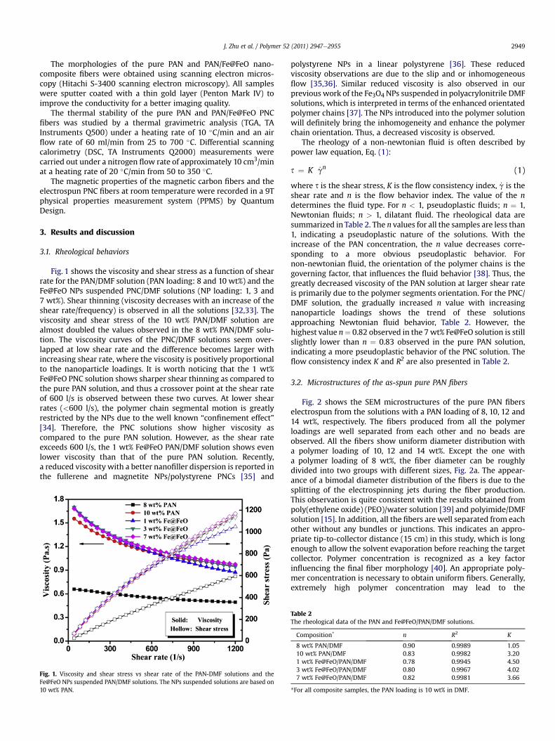
Fig. 1 shows the viscosity and shear stress as a function of shearrate for the PAN/DMF solution (PAN loading: 8 and 10 wt%) and theFe@FeO NPs suspended PNC/DMF solutions (NP loading: 1, 3 and7 wt%). Shear thinning (viscosity decreases with an increase of theshear rate/frequency) is observed in all the solutions [32,33]. Theviscosity and shear stress of the 10 wt% PAN/DMF solution arealmost doubled the values observed in the 8 wt% PAN/DMF solu-tion. The viscosity curves of the PNC/DMF solutions seem over-lapped at low shear rate and the difference becomes larger withincreasing shear rate, where the viscosity is positively proportionalto the nanoparticle loadings. It is worth noticing that the 1 wt%Fe@FeO PNC solution shows sharper shear thinning as compared tothe pure PAN solution, and thus a crossover point at the shear rateof 600 l/s is observed between these two curves. At lower shearrates (<600 l/s), the polymer chain segmental motion is greatlyrestricted by the NPs due to the well known “confinement effect”[34]. Therefore, the PNC solutions show higher viscosity ascompared to the pure PAN solution. However, as the shear rateexceeds 600 l/s, the 1 wt% Fe@FeO PAN/DMF solution shows evenlower viscosity than that of the pure PAN solution. Recently,a reduced viscosity with a better nanofiller dispersion is reported inthe fullerene and magnetite NPs/polystyrene PNCs [35] and
Fig. 1. Viscosity and shear stress vs shear rate of the PAN-DMF solutions and theFe@FeO NPs suspended PAN/DMF solutions. The NPs suspended solutions are based on10 wt% PAN.
polystyrene NPs in a linear polystyrene [36]. These reducedviscosity observations are due to the slip and or inhomogeneousflow [35,36]. Similar reduced viscosity is also observed in ourprevious work of the Fe3O4 NPs suspended in polyacrylonitrile DMFsolutions, which is interpreted in terms of the enhanced orientatedpolymer chains [37]. The NPs introduced into the polymer solutionwill definitely bring the inhomogeneity and enhance the polymerchain orientation. Thus, a decreased viscosity is observed.
The rheology of a non-newtonian fluid is often described bypower law equation, Eq. (1):
s ¼ K _gn (1)
where s is the shear stress, K is the flow consistency index, _g is theshear rate and n is the flow behavior index. The value of the ndetermines the fluid type. For n < 1, pseudoplastic fluids; n ¼ 1,Newtonian fluids; n > 1, dilatant fluid. The rheological data aresummarized in Table 2. The n values for all the samples are less than1, indicating a pseudoplastic nature of the solutions. With theincrease of the PAN concentration, the n value decreases corre-sponding to a more obvious pseudoplastic behavior. Fornon-newtonian fluid, the orientation of the polymer chains is thegoverning factor, that influences the fluid behavior [38]. Thus, thegreatly decreased viscosity of the PAN solution at larger shear rateis primarily due to the polymer segments orientation. For the PNC/DMF solution, the gradually increased n value with increasingnanoparticle loadings shows the trend of these solutionsapproaching Newtonian fluid behavior, Table 2. However, thehighest value n¼ 0.82 observed in the 7wt% Fe@FeO solution is stillslightly lower than n ¼ 0.83 observed in the pure PAN solution,indicating a more pseudoplastic behavior of the PNC solution. Theflow consistency index K and R2 are also presented in Table 2.
3.2. Microstructures of the as-spun pure PAN fibers
Fig. 2 shows the SEM microstructures of the pure PAN fiberselectrospun from the solutions with a PAN loading of 8, 10, 12 and14 wt%, respectively. The fibers produced from all the polymerloadings are well separated from each other and no beads areobserved. All the fibers show uniform diameter distribution witha polymer loading of 10, 12 and 14 wt%. Except the one witha polymer loading of 8 wt%, the fiber diameter can be roughlydivided into two groups with different sizes, Fig. 2a. The appear-ance of a bimodal diameter distribution of the fibers is due to thesplitting of the electrospinning jets during the fiber production.This observation is quite consistent with the results obtained frompoly(ethylene oxide) (PEO)/water solution [39] and polyimide/DMFsolution [15]. In addition, all the fibers are well separated from eachother without any bundles or junctions. This indicates an appro-priate tip-to-collector distance (15 cm) in this study, which is longenough to allow the solvent evaporation before reaching the targetcollector. Polymer concentration is recognized as a key factorinfluencing the final fiber morphology [40]. An appropriate poly-mer concentration is necessary to obtain uniform fibers. Generally,extremely high polymer concentration may lead to the
Table 2The rheological data of the PAN and Fe@FeO/PAN/DMF solutions.
Composition* n R2 K
8 wt% PAN/DMF 0.90 0.9989 1.0510 wt% PAN/DMF 0.83 0.9982 3.201 wt% Fe@FeO/PAN/DMF 0.78 0.9945 4.503 wt% Fe@FeO/PAN/DMF 0.80 0.9967 4.027 wt% Fe@FeO/PAN/DMF 0.82 0.9981 3.66
*For all composite samples, the PAN loading is 10 wt% in DMF.
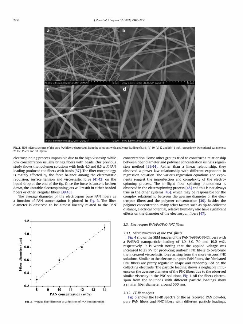
Fig. 2. SEMmicrostructures of the pure PAN fibers electrospun from the solutions with a polymer loading of (a) 8, (b) 10, (c) 12 and (d) 14 wt%, respectively. Operational parameters:20 kV, 15 cm and 10 ml/min.
J. Zhu et al. / Polymer 52 (2011) 2947e29552950
electrospinning process impossible due to the high viscosity, whilelow concentration usually brings fibers with beads. Our previousstudy shows that polymer solutions with both 4.0 and 6.5 wt% PANloading produced the fibers with beads [37]. The fiber morphologyis mainly affected by the force balance among the electrostaticrepulsion, surface tension and viscoelastic force [41,42] on theliquid drop at the end of the tip. Once the force balance is brokendown, the unstable electrospinning jets will result in either beadedfibers or other irregular fibers [39,43].
The average diameter of the electrospun pure PAN fibers asa function of PAN concentration is plotted in Fig. 3. The fiberdiameter is observed to be almost linearly related to the PAN
Fig. 3. Average fiber diameter as a function of PAN concentration.
concentration. Some other groups tried to construct a relationshipbetween fiber diameter and polymer concentration using a regres-sion method [39,44]. Rather than a linear relationship, theyobserved a power law relationship with different exponents inregression equation. The various regression equations and expo-nents suggest the imperfection and complexity of the electro-spinning process. The in-flight fiber splitting phenomena isobserved in the electrospinning process [45] and this is not alwaystrue in the other systems [46], which may be responsible for thecomplex relationship between the average diameter of the elec-trospun fibers and the polymer concentration [39]. Besides thepolymer concentration, many other factors such as tip-to-collectordistance, electrical potential, relative humidity also have significanteffects on the diameter of the electrospun fibers [47].
3.3. Electrospun PAN/Fe@FeO PNC fibers
3.3.1. Microstructures of the PNC fibersFig. 4 shows the SEM images of the PAN/Fe@FeO PNC fibers with
a Fe@FeO nanoparticle loading of 1.0, 3.0, 7.0 and 10.0 wt%,respectively. It is worth noting that the applied voltage wasincreased to 25 kV for producing uniform PNC fibers to overcomethe increased viscoelastic force arising from the more viscous PNCsolutions. Similar to the electrospun pure PAN fibers, the fabricatedPNC fibers are pretty regular in shape and randomly lied on thecollecting electrode. The particle loading shows a negligible influ-ence on the average diameter of the PNC fibers due to the observedsimilar viscosity in the PNC solutions, Fig. 1. All the fibers electro-spun from the solutions with different particle loadings showa similar fiber diameter around 500 nm.
3.3.2. FT-IR analysisFig. 5 shows the FT-IR spectra of the as received PAN powder,
pure PAN fibers and PNC fibers with different particle loadings,
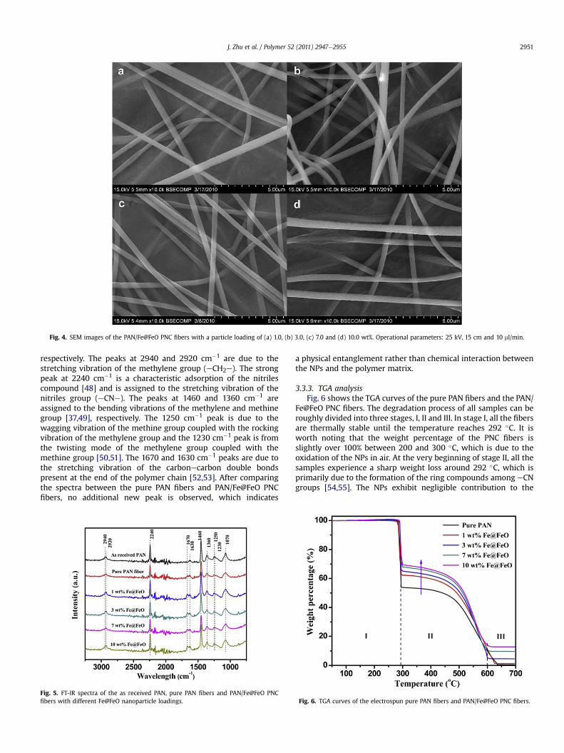
Fig. 4. SEM images of the PAN/Fe@FeO PNC fibers with a particle loading of (a) 1.0, (b) 3.0, (c) 7.0 and (d) 10.0 wt%. Operational parameters: 25 kV, 15 cm and 10 ml/min.
J. Zhu et al. / Polymer 52 (2011) 2947e2955 2951
respectively. The peaks at 2940 and 2920 cm�1 are due to thestretching vibration of the methylene group (eCH2e). The strongpeak at 2240 cm�1 is a characteristic adsorption of the nitrilescompound [48] and is assigned to the stretching vibration of thenitriles group (eCNe). The peaks at 1460 and 1360 cm�1 areassigned to the bending vibrations of the methylene and methinegroup [37,49], respectively. The 1250 cm�1 peak is due to thewagging vibration of the methine group coupled with the rockingvibration of the methylene group and the 1230 cm�1 peak is fromthe twisting mode of the methylene group coupled with themethine group [50,51]. The 1670 and 1630 cm�1 peaks are due tothe stretching vibration of the carbonecarbon double bondspresent at the end of the polymer chain [52,53]. After comparingthe spectra between the pure PAN fibers and PAN/Fe@FeO PNCfibers, no additional new peak is observed, which indicates
Fig. 5. FT-IR spectra of the as received PAN, pure PAN fibers and PAN/Fe@FeO PNCfibers with different Fe@FeO nanoparticle loadings.
a physical entanglement rather than chemical interaction betweenthe NPs and the polymer matrix.
3.3.3. TGA analysisFig. 6 shows the TGA curves of the pure PAN fibers and the PAN/
Fe@FeO PNC fibers. The degradation process of all samples can beroughly divided into three stages, I, II and III. In stage I, all the fibersare thermally stable until the temperature reaches 292 �C. It isworth noting that the weight percentage of the PNC fibers isslightly over 100% between 200 and 300 �C, which is due to theoxidation of the NPs in air. At the very beginning of stage II, all thesamples experience a sharp weight loss around 292 �C, which isprimarily due to the formation of the ring compounds among eCNgroups [54,55]. The NPs exhibit negligible contribution to the
Fig. 6. TGA curves of the electrospun pure PAN fibers and PAN/Fe@FeO PNC fibers.
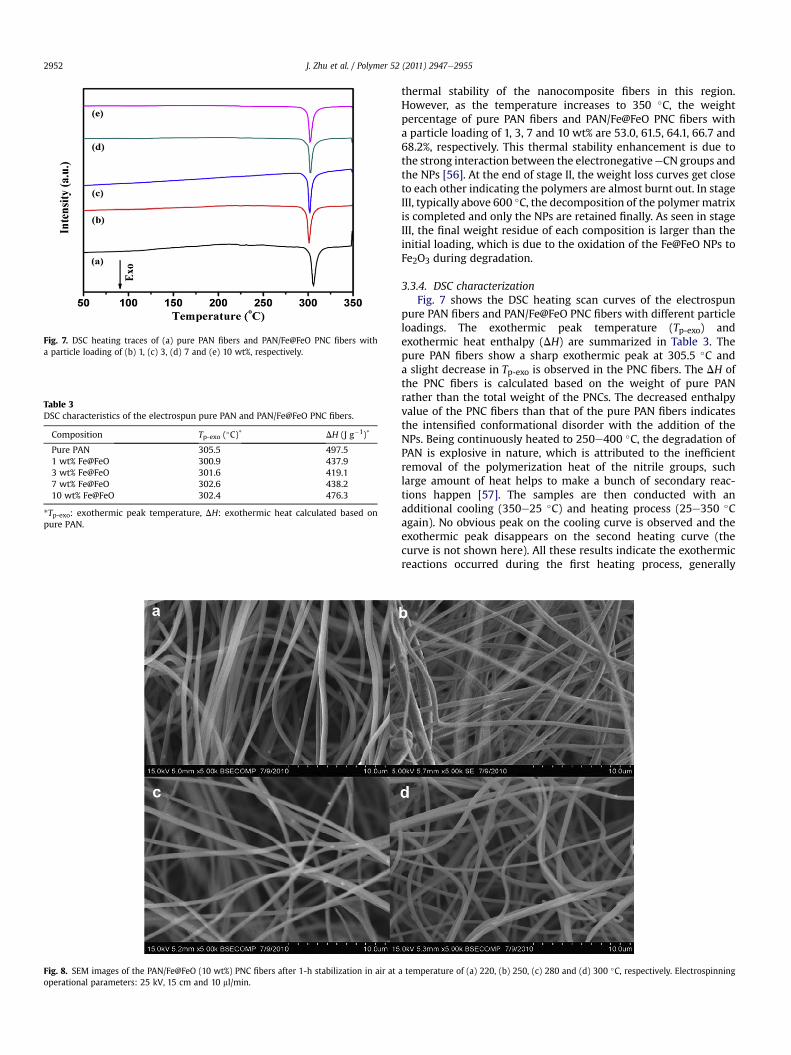
Fig. 7. DSC heating traces of (a) pure PAN fibers and PAN/Fe@FeO PNC fibers witha particle loading of (b) 1, (c) 3, (d) 7 and (e) 10 wt%, respectively.
Table 3DSC characteristics of the electrospun pure PAN and PAN/Fe@FeO PNC fibers.
Composition Tp-exo (�C)* DH (J g�1)*
Pure PAN 305.5 497.51 wt% Fe@FeO 300.9 437.93 wt% Fe@FeO 301.6 419.17 wt% Fe@FeO 302.6 438.210 wt% Fe@FeO 302.4 476.3
*Tp-exo: exothermic peak temperature, DH: exothermic heat calculated based onpure PAN.
Fig. 8. SEM images of the PAN/Fe@FeO (10 wt%) PNC fibers after 1-h stabilization in air atoperational parameters: 25 kV, 15 cm and 10 ml/min.
J. Zhu et al. / Polymer 52 (2011) 2947e29552952
thermal stability of the nanocomposite fibers in this region.However, as the temperature increases to 350 �C, the weightpercentage of pure PAN fibers and PAN/Fe@FeO PNC fibers witha particle loading of 1, 3, 7 and 10 wt% are 53.0, 61.5, 64.1, 66.7 and68.2%, respectively. This thermal stability enhancement is due tothe strong interaction between the electronegativeeCN groups andthe NPs [56]. At the end of stage II, the weight loss curves get closeto each other indicating the polymers are almost burnt out. In stageIII, typically above 600 �C, the decomposition of the polymermatrixis completed and only the NPs are retained finally. As seen in stageIII, the final weight residue of each composition is larger than theinitial loading, which is due to the oxidation of the Fe@FeO NPs toFe2O3 during degradation.
3.3.4. DSC characterizationFig. 7 shows the DSC heating scan curves of the electrospun
pure PAN fibers and PAN/Fe@FeO PNC fibers with different particleloadings. The exothermic peak temperature (Tp-exo) andexothermic heat enthalpy (DH) are summarized in Table 3. Thepure PAN fibers show a sharp exothermic peak at 305.5 �C anda slight decrease in Tp-exo is observed in the PNC fibers. The DH ofthe PNC fibers is calculated based on the weight of pure PANrather than the total weight of the PNCs. The decreased enthalpyvalue of the PNC fibers than that of the pure PAN fibers indicatesthe intensified conformational disorder with the addition of theNPs. Being continuously heated to 250e400 �C, the degradation ofPAN is explosive in nature, which is attributed to the inefficientremoval of the polymerization heat of the nitrile groups, suchlarge amount of heat helps to make a bunch of secondary reac-tions happen [57]. The samples are then conducted with anadditional cooling (350e25 �C) and heating process (25e350 �Cagain). No obvious peak on the cooling curve is observed and theexothermic peak disappears on the second heating curve (thecurve is not shown here). All these results indicate the exothermicreactions occurred during the first heating process, generally
a temperature of (a) 220, (b) 250, (c) 280 and (d) 300 �C, respectively. Electrospinning
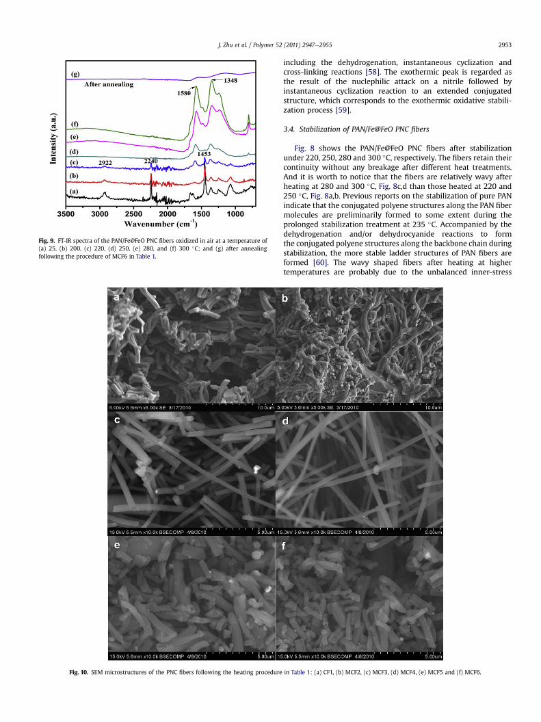
Fig. 9. FT-IR spectra of the PAN/Fe@FeO PNC fibers oxidized in air at a temperature of(a) 25, (b) 200, (c) 220, (d) 250, (e) 280, and (f) 300 �C; and (g) after annealingfollowing the procedure of MCF6 in Table 1.
Fig. 10. SEM microstructures of the PNC fibers following the heating procedure
J. Zhu et al. / Polymer 52 (2011) 2947e2955 2953
including the dehydrogenation, instantaneous cyclization andcross-linking reactions [58]. The exothermic peak is regarded asthe result of the nuclephilic attack on a nitrile followed byinstantaneous cyclization reaction to an extended conjugatedstructure, which corresponds to the exothermic oxidative stabili-zation process [59].
3.4. Stabilization of PAN/Fe@FeO PNC fibers
Fig. 8 shows the PAN/Fe@FeO PNC fibers after stabilizationunder 220, 250, 280 and 300 �C, respectively. The fibers retain theircontinuity without any breakage after different heat treatments.And it is worth to notice that the fibers are relatively wavy afterheating at 280 and 300 �C, Fig. 8c,d than those heated at 220 and250 �C, Fig. 8a,b. Previous reports on the stabilization of pure PANindicate that the conjugated polyene structures along the PAN fibermolecules are preliminarily formed to some extent during theprolonged stabilization treatment at 235 �C. Accompanied by thedehydrogenation and/or dehydrocyanide reactions to formthe conjugated polyene structures along the backbone chain duringstabilization, the more stable ladder structures of PAN fibers areformed [60]. The wavy shaped fibers after heating at highertemperatures are probably due to the unbalanced inner-stress
in Table 1: (a) CF1, (b) MCF2, (c) MCF3, (d) MCF4, (e) MCF5 and (f) MCF6.
J. Zhu et al. / Polymer 52 (2011) 2947e29552954
around the outer surface during shrinkage as the dehydrogenationand/or dehydrocyanide reaction proceeds.
The evolution of the fiber composition is further evidenced bythe FT-IR spectra, Fig. 9. The gradually decrease in the intensities ofthe C^N for saturated nitriles at 2240 cm�1 and the aliphatic CeHat 1453 cm�1 and 2922 cm�1 with increasing the heating temper-ature from 25 �C to 220 �C confirms the reactions of dehydroge-nation and dehydrocyanide. With further increasing the heatingtemperature, these peaks disappear and several new peaksbetween 1200 and 1600 cm�1 are observed, Fig. 9def, indicatingthe growth of the C]C and C]N bands [60]. After annealing, thepolymer fibers are converted to carbon fibers accompanied by theloss of the peaks in the typical range of 1000e1600 cm�1, Fig. 9g.
3.5. Carbonization of the PAN/Fe@FeO PNC fibers
The stabilized PAN/Fe@FeO PNC fibers are subjected to furtherheating process under nitrogen with the aim to produce carbonnanocomposite fibers. Fig. 10 shows the carbon nanocompositefibers after experiencing different stabilization and carbonizationprocesses. These fibers can be classified into three groups based onthe morphologies. Fig. 10a,b shows the wavy fibers bundledtogether and some unexpected debris is observed in Fig. 10b.Fig. 10c,d presents the well-separated straight carbon nano-composite fibers with appreciable fiber length. Fig. 10e,f depictsthe separated fibers in short length. The significant difference inthe fiber morphology is majorly attributed to the stabilization timeand temperature, carbonization time and temperature. The fiberbundling and fusion, Fig. 10a,b is probably due to the higherheating rate (25e280 �C within 1 h) and longer stabilization time(3.5 h). The high heating rate is able to introduce larger temper-ature gradient directing from central to surface, which inevitablybrings larger inner stress inside the fiber. Finally, the fibers showwavy shaped structure and even bundle together to minimize theinner stress. With the elongation of the stabilization process, thedehydrogenation and dehydrocyanide reactions may happen notonly on a single fiber, but also between the bundled fibers, andthus the “fusion” phenomenon is observed, Fig. 10a,b. Bydecreasing the heating rate (25e250 �C within 2 h), stabilizationtemperature (from 280 to 250 �C) and duration (from 3.5 to 1 h),the high quality carbon nanocomposite fibers with a diameter
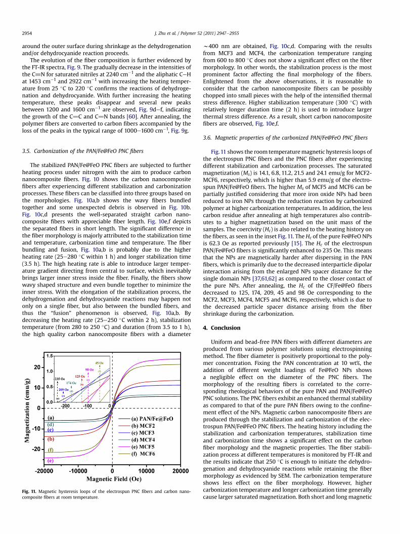
Fig. 11. Magnetic hysteresis loops of the electrospun PNC fibers and carbon nano-composite fibers at room temperature.
w400 nm are obtained, Fig. 10c,d. Comparing with the resultsfrom MCF3 and MCF4, the carbonization temperature rangingfrom 600 to 800 �C does not show a significant effect on the fibermorphology. In other words, the stabilization process is the mostprominent factor affecting the final morphology of the fibers.Enlightened from the above observations, it is reasonable toconsider that the carbon nanocomposite fibers can be possiblychopped into small pieces with the help of the intensified thermalstress difference. Higher stabilization temperature (300 �C) withrelatively longer duration time (2 h) is used to introduce largerthermal stress difference. As a result, short carbon nanocompositefibers are observed, Fig. 10e,f.
3.6. Magnetic properties of the carbonized PAN/Fe@FeO PNC fibers
Fig.11 shows the room temperaturemagnetic hysteresis loops ofthe electrospun PNC fibers and the PNC fibers after experiencingdifferent stabilization and carbonization processes. The saturatedmagnetization (Ms) is 14.1, 6.8, 11.2, 21.5 and 24.1 emu/g for MCF2-MCF6, respectively, which is higher than 5.9 emu/g of the electro-spun PAN/Fe@FeO fibers. The higher Ms of MCF5 and MCF6 can bepartially justified considering that more iron oxide NPs had beenreduced to iron NPs through the reduction reaction by carbonizedpolymer at higher carbonization temperatures. In addition, the lesscarbon residue after annealing at high temperatures also contrib-utes to a higher magnetization based on the unit mass of thesamples. The coercivity (Hc) is also related to the heating history onthe fibers, as seen in the inset Fig. 11. The Hc of the pure Fe@FeO NPsis 62.3 Oe as reported previously [15]. The Hc of the electrospunPAN/Fe@FeO fibers is significantly enhanced to 235 Oe. This meansthat the NPs are magnetically harder after dispersing in the PANfibers, which is primarily due to the decreased interparticle dipolarinteraction arising from the enlarged NPs spacer distance for thesingle domain NPs [37,61,62] as compared to the closer contact ofthe pure NPs. After annealing, the Hc of the CF/Fe@FeO fibersdecreased to 125, 174, 209, 45 and 98 Oe corresponding to theMCF2, MCF3, MCF4, MCF5 and MCF6, respectively, which is due tothe decreased particle spacer distance arising from the fibershrinkage during the carbonization.
4. Conclusion
Uniform and bead-free PAN fibers with different diameters areproduced from various polymer solutions using electrospinningmethod. The fiber diameter is positively proportional to the poly-mer concentration. Fixing the PAN concentration at 10 wt%, theaddition of different weight loadings of Fe@FeO NPs showsa negligible effect on the diameter of the PNC fibers. Themorphology of the resulting fibers is correlated to the corre-sponding rheological behaviors of the pure PAN and PAN/Fe@FeOPNC solutions. The PNC fibers exhibit an enhanced thermal stabilityas compared to that of the pure PAN fibers owing to the confine-ment effect of the NPs. Magnetic carbon nanocomposite fibers areproduced through the stabilization and carbonization of the elec-trospun PAN/Fe@FeO PNC fibers. The heating history including thestabilization and carbonization temperatures, stabilization timeand carbonization time shows a significant effect on the carbonfiber morphology and the magnetic properties. The fiber stabili-zation process at different temperatures is monitored by FT-IR andthe results indicate that 250 �C is enough to initiate the dehydro-genation and dehydrocyanide reactions while retaining the fibermorphology as evidenced by SEM. The carbonization temperatureshows less effect on the fiber morphology. However, highercarbonization temperature and longer carbonization time generallycause larger saturatedmagnetization. Both short and longmagnetic
J. Zhu et al. / Polymer 52 (2011) 2947e2955 2955
carbon nanocomposite fibers can be simply produced by changingthe heating procedure.
Acknowledgments
This project is financially supported by the Research Start-UpGrant and Research Enhancement Grant from Lamar University.We acknowledge the support from the National Science Foundation- Nanoscale Interdisciplinary Research Team and Materials Pro-cessing andManufacturing (CMMI 10-30755) to obtain the DSC andTGA. D. P. Young acknowledges support from the NSF under GrantNo. DMR 10-05764.
References
[1] Reneker DH, Yarin AL. Polymer 2008;49:2387e425.[2] Zhu J, Wei S, Patil R, Rutman D, Kucknoor AS, Wang A, et al. Polymer 2011;52:
1954e62.[3] Huang ZM, Zhang YZ, Kotaki M, Ramakrishna S. Compos Sci Technol 2003;63:
2223e53.[4] Lai C, Guo Q, Wu X, Reneker DH, Hou H. Nanotechnology 2008;19:195303.[5] Wang G, Ji Y, Huang X, Yang X, Gouma PI, Dudley M. J Phys Chem B 2006;110:
23777e82.[6] Chronakis IS. J Mater Process Technol 2005;167:283e93.[7] Li D, Xia Y. Nano Lett 2003;3:555e60.[8] Wang D, Li K, Teo WK. J Membr Sci 1996;115:85e108.[9] Ma Z, Kotaki M, Ramakrishna S. J Membr Sci 2006;272:179e87.
[10] Shimizu Y, Okuno YI, Uryu K, Ohtsubo S, Watanabe A. Water Res 1996;30:2385e92.
[11] Krzysztof P, Njuguna J. Thermal degradation of polymeric materials. Shaw-bury, UK: Rapra Technology; 2005.
[12] Wind JD, Sirard SM, Paul DR, Green PF, Johnston KP, Koros WJ. Macromole-cules 2003;36:6442e8.
[13] Zhu J,WeiS,Ryu J, BudhathokiM,LiangG,GuoZ. JMaterChem2010;20:4937e48.[14] Zhu J, Wei S, Zhang L, Mao Y, Ryu J, Haldolaarachchige N, et al. J Mater Chem
2011;21:3952e9.[15] Zhu J, Wei S, Chen X, Karki AB, Rutman D, Young DP, et al. J Phys Chem C 2010;
114:8844e50.[16] Cao X, Habibi Y, Lucia LA. J Mater Chem 2009;19:7137e45.[17] Chen X, Wei S, Gunesoglu C, Zhu J, Southworth CS, Sun L, et al. Macromol
Chem Phys 2010;211:1775e83.[18] Zhu J, Wei S, Alexander M, Dang TD, Ho TC, Guo Z. Adv Funct Mater 2010;20:
3076e84.[19] Zhu J, Feng X, Shi Y, Wang H, Lu X. J Nanosci Nanotechnol 2009;9:5958e65.[20] Zhou Z, Lai C, Zhang L, Qian Y, Hou H, Reneker DH, et al. Polymer 2009;50:
2999e3006.[21] Kim C, Choi YO, Lee WJ, Yang KS. Electrochim Acta 2004;50:883e7.[22] Suzuki M. Carbon 1994;32:577e86.
[23] Endo M, Kim C, Nishimura K, Fujino T, Miyashita K. Carbon 2000;38:183e97.[24] Steigerwalt ES, Deluga GA, Lukehart CM. J Phys Chem B 2002;106:760e6.[25] Morgan PE. Carbon fibers and their composites carbon fibers and their
composites. Boca Raton, FL: CRC Press; 2005. 185e267.[26] Morita M, Nishimura N, Matsuda Y. Electrochim Acta 1993;38:1721e6.[27] Teo WE, Ramakrishna S. Nanotechnology 2006;17:R89e106.[28] Dai H, Gong J, Kim H, Lee D. Nanotechnology 2002;13:674e7.[29] Shao C, Kim HY, Gong J, Ding B, Lee DR, Park SJ. Mater Lett 2003;57:1579e84.[30] Viswanathamurthi P, Bhattarai N, Kim HY, Lee DR, Kim SR, Morris MA. Chem
Phys Lett 2003;374:79e84.[31] Guan H, Shao C, Chen B, Gong J, Yang X. Inorg Chem Commun 2003;6:
1409e11.[32] Ugaz VM, Cinader DK, Burghardt WR. Macromolecules 1997;30:1527e30.[33] Zhu J, Wei S, Yadav A, Guo Z. Polymer 2010;51:2643e51.[34] Rittigstein P, Priestley RD, Broadbelt LJ, Torkelson JM. Nat Mater 2007;6:
278e82.[35] Tuteja A, Duxbury PM, Mackay ME. Macromolecules 2007;40:9427e34.[36] Mackay ME, Dao TT, Tuteja A, Ho DL, Van Horn B, Kim HC, et al. Nat Mater
2003;2:762e6.[37] Zhang D, Karki AB, Rutman D, Young DP, Wang A, Cocke D, et al. Polymer
2009;50:4189e98.[38] Grabowski DA, Schmidt C. Macromolecules 1994;27:2632e4.[39] Deitzel JM, Kleinmeyer J, Harris D, Beck Tan NC. Polymer 2001;42:261e72.[40] Chen DR, Pui DYH, Kaufman SL. J Aerosol Sci 1995;26:963e77.[41] Li D, Xia Y. Adv Mater 2004;16:1151e70.[42] Ji L, Saquing C, Khan SA, Zhang X. Nanotechnology 2008;19:085605.[43] Zhang W, Wang Y, Sun C. J Polym Res 2007;14:467e74.[44] Baumgarten PK. J Colloid Interface Sci 1971;36:71e9.[45] Doshi J, Reneker DH. J Electrostat 1995;35:151e60.[46] Reneker D, Yarin A, Fong H, Koombhongse S. J Appl Phys 2000;87:4531e47.[47] Thompson CJ, Chase GG, Yarin AL, Reneker DH. Polymer 2007;48:6913e22.[48] Silverstein RM, Webster FX, Kiemle D. Spectrometric identification of organic
compounds. Hoboken: John Wiley and Sons, inc.; 2005.[49] Mathur RB, Bahl OP, Sivaram P. Curr Sci 1992;62:662e9.[50] Minagawa M, Miyano K, Takahashi M, Yoshii F. Macromolecules 1988;21:
2387e91.[51] Liang CY, Krimm S. J Polym Sci 1958;31:513.[52] De P, Sathyanarayana DN, Sadasivamurthy P, Sridhar S. Eur Polym J 2002;38:
847e55.[53] De P, Sathyanarayana DN, Sadasivamurthy P, Sridhar S. Polymer 2001;42:
8587e93.[54] Sahiner N, Pekel N, Güven O. React Funct Polym 1999;39:139e46.[55] Bastow T, Hardin SG, Turney TW. J Mater Sci 1991;26:1443e53.[56] Yu T, Lin J, Xu J, Chen T, Lin S, Tian X. Compos Sci Technol 2007;67:
3219e25.[57] Kim HS. J Polym Sci B 1996;34:1181e6.[58] Sivy GT, Gordon Iii B, Coleman MM. Carbon 1983;21:573e8.[59] Badawy SM, Dessouki AM. J Phys Chem B 2003;107:11273e9.[60] Usami T, Itoh T, Ohtani H, Tsuge S. Macromolecules 1990;23:2460e5.[61] Guo Z, Lei K, Li Y, Ng HW, Prikhodko S, Hahn HT. Compos Sci Technol 2008;68:
1513e20.[62] Guo Z, Lin H, Karki AB, Wei S, Young DP, Park S, et al. Compos Sci Technol
2008;68:2551e6.