Magnetic Levitation Train by Shaheen Galgali_seminar report final
Upload
truongcongCategory
view
221download
0
1
Magnetic Levitation Train Final Report
By: Dusty Funk
& Kyle Getsla
Project Advisor: Dr. Anakwa
Date: May 12, 2006
Bradley University Department of Electrical and Computer Engineering

2
Abstract
The objective of this project is to create a laboratory scale magnetic levitating train model using Inductrack technology developed by Dr. Richard Post from Lawrence Livermore National Labs, Previous work by Paul Friend is discussed as well as the physics associated with Inductrack. The levitation and propulsion systems built in lab is described. The conclusion includes the results and suggestions for future work on the maglev train.

3
Table of Contents Project Summary ...................................................................................................... 1 Basic Concepts.......................................................................................................... 1
Halbach Array............................................................................................... 1 Track............................................................................................................. 1 Propulsion ………........................................................................................ 2
Inductrack Technology.............................................................................................. 3
Simulation...................................................................................................... 4 Block Diagram........................................................................................................... 6
Propulsion...................................................................................................... 6 Levitation....................................................................................................... 7
Previous Work........................................................................................................... 7 Levitation................................................................................................................... 8 Wheel Fabrication.......................................................................................... 8 Track Fabrication.......................................................................................... 10 Car Fabrication...............................................................................................11 Testing & Results...........................................................................................12
Suggested Improvements.............................................................................. 13 Propulsion.................................................................................................................. 14 Controller....................................................................................................... 14
Linear Synchronous Motor Fabrication......................................................... 14 Track Fabrication........................................................................................... 16 Car Fabrication …………............................................................................. 17 Testing ……………………...........................................................................17 Results………………….…........................................................................... 18 Suggested Improvements............................................................................... 18
Conclusion ................................................................................................................ 18 Equipment Division.................................................................................................. 19 Equipment List…….................................................................................................. 19 Patents........................................................................................................................ 20 Acknowledgments......................................................................................................21 Bibliography.............................................................................................................. 21

1
Project Summary The goal of the Magnetic Levitation Train (MAGLEV) project is to develop a small scale magnetic levitation train based on Inductrack technology developed by Dr. Richard Post from Lawrence Livermore National Labs (LLNL). This project is a continuation of work done by Paul Friend in 2004. The MAGLEV project consists of two construction phases. Phase I proves that levitation is possible by redesign of a wheel track system. Phase II involves construction of an oval track to design and test a linear synchronous motor (LSM) for propulsion. Note that Phases I & II are independent and thus can be done simultaneously. Basic Concepts Basic Concepts associated with MAGLEV are the Halbach Array, the Levitation Track, and the Propulsion system. Halbach Array The Halbach Arrays in the train cancel the magnetic field above the magnets while strengthening the field below them as shown in Figure 2.3. Each array is built by placing magnets at 90° angles relative to each other. The current magnets in the test setup are grade 38, Neodymium-Iron-Boron (NdFeB), 12mm cube magnets.
Figure 1.1 – Single Halbach Array
Track Laminated sheets can be chemically or mechanically etched to create slots. The slots serve to separate the track into rails which act as individual inductors. As the train moves along the track, the onboard permanent magnets induce a current through each rail, which induces a magnetic field opposing the field of the permanent magnets on the train. An illustration of the copper track being used for project is shown in Figure 2.1, as simulated by Lawrence Livermore National Laboratory.

2
Figure 2.1 – Passive Levitation and Guidance Using Copper Sheets
Propulsion A Linear Synchronous Motor (LSM) was chosen to propel the train. A basic top view of an LSM is shown in Figure 2.2 below. It consists of copper wire powered by 3ø AC Power wrapped around slots cut in laminated iron. The iron is laminated to help eliminate eddy currents. Each color represents a different phase with a 120° phase difference between each line.
Figure 2.2 – Linear Synchronous Motor Top View
As current moves through the wire, a magnetic field is induced around each slot in the iron. Figure 2.2 illustrates the magnetic field of each wire in Figure 3.1. Magnets in the car interact with this magnetic field which pushes the car along the rail.

3
0 0.02 0.04 0.06 0.08-1
-0.5
0
0.5
1
Time (s)
Nor
mal
ized
Mag
netic
Fie
ld In
tens
ity
LSM Magnetic Field Intensity
Phase 1Phase 2Phase 3
Figure 3.1 – Magnetic Field of LSM
Inductrack Technology The Inductrack Technology uses the basic concepts above to first propel and then levitate a train. The train consists of at least two sets of Halbach arrays. One set is placed over the track to levitate the train, while the other set is placed above the motor to provide propulsion. When the motor is powered, the train begins to move on wheels along the track. The levitation Halbach array induces current in the track which induces a magnetic field around the slits to oppose the magnetic field of the levitation Halbach array. This produces the levitation. The faster the train moves, the higher the train levitates. Paul Friend’s research helped him plot levitation height vs. the velocity of the train as shown in Figure 4.1. In this example, the train reaches a peak height due to the lessened effect of the magnets on the track. The height and velocity of the track are dependent on parameters of the track and Halbach array.

4
Figure 4.1 – Levitation height vs. Velocity
Simulation One way to model MAGLEV is with a simple resistor and inductor in series shown in Figure 4.2.
Figure 4.2 – MAGLEV Model
The resistor and inductor represent the resistivity and inductance respectively of the track. The frequency represents the speed of the train. The transfer function is: I(s) 1/L ---------- = ----------------- V(s) (s + R/L)

5
The frequency response is shown in Figure 5.1.
Figure 5.1 – MAGLEV Frequency Response
When the Halbach arrays move over the track, there are two forces that are introduced: a drag force and a levitation force. The drag force, related to the resistivity, opposes the motion of the train, and the levitation force, related to the inductance, provides levitation. The transfer function above illustrates that as the drag force begins to decrease, the levitation force increases. The phase shift relates to the drag forces becoming levitation forces. At 45° phase (R/L pole), levitation can be observed. Therefore it becomes extremely important to move this pole as close to zero as possible to provide levitation at lower speeds.

6
Block Diagram The highest level system block diagram is shown in Figure 6.1. 3ø AC Power is being used to control the levitation height and train velocity.
Figure 6.1 – High-Level Block Diagram
Figure 6.2 breaks the block diagram down one level. Here the 3ø AC Power (variable) is being fed into a controller that is able to vary the frequency. As mentioned above, the frequency controls how fast the train is able to move on the track. The overall MAGLEV system is made up of two subsystems: propulsion and levitation.
Figure 6.2 – Next Level Block Diagram Propulsion As mentioned earlier, a linear synchronous motor (LSM) will be used to propel the train along the track. Figure 6.3 describes the propulsion system. All the propulsion subsystem is doing is taking the current from the controller and inducing magnetism at each of the slots. This produces a train velocity when the train is synchronized with the track.
3ø AC Power Controller Train
VelocityInduced
Magnetism
Figure 6.3 – Propulsion Subsystem Block Diagram

7
Levitation The levitation of the train is completely dependent on the train’s velocity. The faster the Halbach arrays move across the surface of the track, the higher the train levitates. Figure 7.1 describes exactly how levitation is accomplished. First, the train’s velocity induces a current in the track. This current then induces a magnetic field that levitates the train. This signal is fed back through a levitation constant that is defined by properties of the levitation Halbach array and the track design.
Figure 7.1 – Levitation Subsystem
Previous Work In 2004, Paul Friend began working on a MAGLEV model with the help of Dr. Richard Post, PhD. With Dr. Post’s equations and concepts, Paul was able to create a sophisticated Matlab program that can calculate various train parameters (velocity, drag force, etc.) based off of the specifications of the train car and track. Using his program, Paul then constructed a wheel-track test platform (Figure 7.2).
Figure 7.2 – Paul Friend’s Testbench

8
Paul Friend’s Matlab program is shown in Figure 8.1. The left column contains the design specifications for the train and track. The middle column shows the outputs based on the entered parameters. Finally, the right column shows graphs of the forces acting on the train at various velocities.
Figure 8.1 – Matlab Program
Levitation The goal of the levitation portion of this project was to prove that levitation is possible and to optimize the track and train to get sufficient levitation at the lowest possible speeds. The Matlab program was used to optimize the track and car parameters using the specifications of cost-effective materials. The design settled on provided 1cm of levitation at about 9m/s. The following subsections will detail the design of the wheel track test platform and car. Wheel Fabrication The wheel used was a 36” diameter racing bicycle tire, which had a standard sprocket attached. Figure 9.1 shows the wheel and stand. The wheel was mounted on a balancing stand and attached to a motor with a gear and chain (Figure 9.3). With a goal of achieving 9m/s, this means that the wheel (2 meter circumference) must spin at 270 rpm

9
if the train begins at less than 1cm above the track. This is necessary in order to observe any levitation. By using a chain and bicycle tire, an imbalanced track can still spin smooth enough to get up to speeds greater than 1000 rpm.
Figure 9.1 Wheel and Stand A frame was built to surround the wheel (Figures 9.2 & 9.3). The frame serves many purposes: to support a motor, to support and contain the train car, and to provide some protection from the wheel itself.
Figure 9.2 Frame and Motor Figure 9.3 Wheel Attached to Motor

10
Track Fabrication The track was created by Chicago WaterJet in Des Plaines, IL (Figure 10.1). Each of the 5 strips measure 5cm wide and 1m long. The specifications were to have cuts made ever 0.5cm with the cuts being 0.05cm wide and 4cm long (centered). However, the smallest width the waterjet process could create was 0.1cm, so this is how wide they are. The track was cut from a 5ft x 3ft sheet of 0.021in thick aluminum sheet metal bought from Lowe’s Home Improvement.
Figure 10.1 Aluminum Track
The track was tied, with fishing line, to 0.25in thick model railroad cork as show in Figure 10.2.
Figure 10.2 Track Mounted to Cork

11
The spokes of the wheel are fastened used steel screws, to which the magnets on the bottom of the car are attracted. In order to limit this attraction, the wheel was mounted to blue Styrofoam blocks in order to move it away from the spokes by just over 1cm. The entire track is mounted to the wheel using fishing line, and the results can be seen in Figure 11.1. A consequence of using the fishing line is that the line stretches as the wheel spins faster due to the centripetal force acting on the track. While the stability of the wheel is unaffected, the car’s rest height must be adjusted so that the wheel doesn’t hit it before the car begins levitating. Despite having about 5m of track fabricated, only one layer of track was used for testing. This means that the required speed for levitation is exactly double that for one layer of track. Since the design was for 9m/s, or 270rpm, this means that 18m/s, or 540rpm, is needed for this altered design. The reasons for using only one layer are explained in the results section.
Figure 11.1 Track Mounted to Wheel Car Fabrication The car was created out of 5cm wide balsa wood. Figure 12.1 shows the top and bottom of the car. A hole was drilled for each magnet of the Halbach arrays. Since each magnet was a 1cm cube, two Halbach arrays could fit in the car. Wings were added to the top of the car to support it while it is not levitating. Wheels were added on the back of the train so that, when the car would levitate, the drag force between the car and the wall would not inhibit the levitation. Figure 12.2 shows the car at rest, without the wheel spinning. Notice that the wall is positioned to keep the car directly over the center of the track. This is important because the car was not molded to fit the shape of the wheel.

12
Figure 12.1 Balsa Wood Car
Figure 12.2 Car at Rest Testing & Results Without the car in place, the wheel can smoothly spin up to 1200rpm with a typical 30Vdc Pittman motor. However, once the car is in place, the speed of the wheel is reduced to less than 250rpm. The drag force created by spinning the wheel works against the car. But since the car is held in place, the drag force acts directly against the track.

13
Not only is the speed of the wheel depleted, but the current that the motor attempts to draw with the car in place (above 9A) will burn out the motor quickly. The first test showed that a stronger motor was needed. A 3ø AC motor was the next choice. However, with no datasheet available, a trial and error approach was required to figure out how to control it. After a few days of experimenting, it was decided that this motor would not fair any better than the Pittman motor. The final choice was a 1/3 Hp DC Motor that could handle up to 115V and 3.4A. In testing, the motor went beyond its specified 3.4A of current at about 20Vdc, with a wheel speed of about 250rpm. The motor could not spin fast enough to generate the back emf required to reach its rated 1/3 Hp. Recall that the gear ratio was 1:4. This means that the motor was only spinning at 63rpm when the wheel was at 250rpm. The final test was to change the gear ratio. It was conceivable that if a 1:1 gear ratio would allow the motor to spin at a higher speed, and thus generate the torque required to go beyond its previous best of 250rpm. A very small gear was attached, and the theory held true. With this adjustment, the wheel (which is now at the same speed as the motor) could be spun at about 300rpm. This speed was achieved at 25Vdc and 3.5A. This was an improvement, but it was still nowhere near the 540rpm required for 1cm of levitation. While levitation is possible at lower speeds, the track stretching at high speeds required that the car start about 1cm above the track. The previous testing problems are the reason that only one layer of track was used. With another layer of track, the drag force would have been doubled. This means that even though the wheel would need to be spun at half the speed, the force acting against the motor would be doubled. In essence, getting the wheel to spin at the specified speed would be just as difficult with one or two layers of track. Since one layer was already on and balanced, a second layer would have created more problems without solving any existing ones. Suggested Improvements The biggest problem is the drag force. A more powerful motor is the obvious solution, but it may not be the most cost-effective. If the track can be mounted so that it doesn’t expand, then the train could be positioned closer to the track. This would allow levitation of less than 1cm to become observable. A good way to measure this levitation would be to attach a position sensor to the stand and precisely measure how much the car has risen. Instead of holding the car in place with wheels and a wall, the car could be attached to two rods on each side for it to slide up and down. The rods would have to be very smooth in order for the friction effect to be minimized enough to be better than current the wheels against the wall. At high speeds, the wheel itself wobbles in the direction of the motor. If the wheel were attached directly to the stand, it would not be able to move in this fashion. This stability is only a problem at speeds above 1000rpm; so this is not an immediate concern.

14
The strengths of this design are the stability and speed of the wheel. The wheel and track can handle the required speeds for levitation, but they just cannot get to those speeds. Propulsion The propulsion system consists of a controller, LSM, track, and car. Controller The controller chosen to vary the frequency of the 3ø AC Power is the Yaskawa GPD 515/G5 in Figure 14.1. This was chosen because its rated from 2 -> 200 HP and can vary frequency from 0.1 -> 400 Hz. This is sufficient for the 9 m/s required.
Figure 14.1 – GPD 515/G5 Controller
Linear Synchronous Motor Fabrication The LSM was designed based on the equation:
V = 2τf
V = Velocity of train τ = Pole Pitch of motor
f = Frequency of 3ø AC Power The pole pitch is the distance between where the wire wraps the first time and where the same wire wraps the second time. This is illustrated in Figure 15.1 on the CAD drawing Kelley Ornamental Iron made for the iron rail. The pole pitch of this design is 3.75” or 9.525 cm. This means that for 9 m/s, the controller must be running at 47.24 Hz.

15
Figure 15.1 – GPD 515/G5 Controller
Kelley Ornamental Iron Company built the motor shown in Figure 15.1 in four sections and bent them at 90° angles to make it easy to transport. It was built from Hot Rolled Steel. Cast steel gives more flux for less field intensity than cast iron and its saturation level is much higher than cast iron. This is illustrated in Figure 15.2. The drawback of using steel rather than iron is when the current is turned off the steel will hold the magnetism longer than the iron, making it harder to stop the train. When they are put together, this corresponds to a diameter of eight feet.
Figure 15.2 – Flux Density vs. Field Intensity for Iron and Steel
τ

16
Kelley Ornamental could not build laminated motor, so the steel was not laminated. This brings up the issue of eddy currents. Because the motor is not laminated, eddy currents will be created between the slots, in between the magnetic fields induced at the slots. The eddy currents will create another magnetic field that will act like a brake for the car, opposing the magnetic field that pushes the car along the track. Ways to solve this problem will be suggested later. Photos of the motor and the motor with wires wrapped are shown in Figure 16.1.
Figure 16.1 – Motor and Wrapped Motor
Track Fabrication The track was constructed by taking two pieces of J-channel siding and gluing them together back-to-back (See Figure 16.2).
Figure 16.1 – Motor and Wrapped Motor
17
J-Channel siding was used because it was a cheap and fast way to construct the track. The car wraps around, underneath the track so the Halbach array can be placed over the LSM. The top of the siding leaves a great place to put wheels that would not allow the magnets to attract to the steel itself. A photo of the car on the track is shown in Figure 17.1.
Figure 17.1 – Car wrapped around track
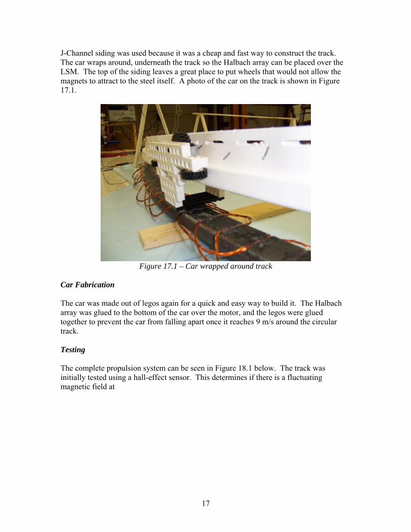
Car Fabrication The car was made out of legos again for a quick and easy way to build it. The Halbach array was glued to the bottom of the car over the motor, and the legos were glued together to prevent the car from falling apart once it reaches 9 m/s around the circular track. Testing The complete propulsion system can be seen in Figure 18.1 below. The track was initially tested using a hall-effect sensor. This determines if there is a fluctuating magnetic field at
18
Figure 18.1 – Complete Propulsion System
Results Initial tests showed that a weak magnetic field, detected by a Hall-effect IC, was created by about 10A of current in the lines. There was a lot of noise in the signal, so a sine wave was not distinguishable. Due to a lengthy design and construction process, extensive testing could not be accomplished in time. Improvements A low-pass filter will be needed to clean up the current signals; the Yaskawa controller’s switching frequency distorted the signal. A controller for the 3ø AC power could be made from scratch. The Yaskawa controller was unable supply the required current to a low resistance load. Even with power resistors in each line, the controller shut itself off. Ideally, the iron core should be laminated to prevent Eddy currents from forming and hurting the efficiency. Additionally, the wire can be wrapped around each slot of the core 3 or more times to get 3 or more times the flux with 1 winding. Conclusion Great progress was made on both the levitation and propulsion systems of the MAGLEV project. This is the second time that students at Bradley University have constructed the pieces of a scale model, MAGLEV train. With each project comes a wealth of information for the next students to digest before making their optimizations to the design. We hope that our progress will see to it that one day Bradley will have a working scale model of a magnetic levitation train.

19
Equipment Division The materials used in this project are split into the Levitation and Propulsion Systems below: Levitation System
Wheel & Stand Agilent E3634A DC Power Supply DC Motor 35” racing bike wheel Balancing stand 0.02” Aluminum Sheet Metal 16 lb test fishing line Misc. Clamps for testing Lumber & Wood Screws Car
1” thick balsa wood Pine-wood derby wheels 10 - 1 cm cube NdFeB magnets Propulsion System
LSM
Yaskawa GPD 515/G5 Controller Cast Steel Core for Motor 3 twisted - 18 gauge magnet wire
Track & Car
J-Channel Vinyl Siding for Track 30 - 3 mm cube NdFeB magnets Legos Scrap Wood
Equipment List Vendor – Gaussboys, www.gaussboys.com The NdFeB magnets are nickel plated, and grade N38. 40 – Block #05 - 12mm Cube Magnets $0.36/each $14.40 total 40 – Block #12 - 6mm Cube Magnets $2.25/each $90.00 total Vendor – Engineering Concepts, http://www.engconcepts.net/ 10 – 4-Sided, Pyramid, N38 Magnets. 10mm base side length, 10mm tall, & 6mm top Price: 10-29 for $0.85 each ($8.50 total for 10)

20
Vendor – Newark, www.newark.com # - Part # - 31K6639 – HALL EFFECT IC PACKAGE/CASE: 3-SIP; PRODUCT DESCRIPTION: RATIOMETRIC LINEAR Price: $0.977 ea Vendor – Lowe’s Home Improvement Wood & fasteners used for construction of wheel stand Aluminum sheet metal Vendor – Venture Hobby Shop Model Railroad Cork Super Glue Balsa Wood Block Racing bicycle tire, chain, gears, and balancing stand, donated by a parent. Lab Equipment: 1/3 HP DC motor 25Vdc Power Supply 5Vdc Power Supply Tektronics TDS-3012b Oscilloscope GPD 515/G5 AC Controller Patents A list of the patents associated with the design of the MAGLEV system, sorted by date, is given below. This list can be thought of as a basic timeline of previous MAGLEV concepts. Richard F Post Inductrack Magnet Configuration U.S. Patent 6,633,217 B2 October 14, 2003 Howard T Coffey Propulsion and Stabilization for Magnetically Levitated Vehicles U.S. Patent 5,222,436 June 29, 2003 Richard F Post Laminated Track Design for Inductrack Maglev System U.S. Patent Pending US 2003/0112105 A1 June 19, 2003 Karl J Lamb, Toby Merrill, Scott D Gossage, Michael T Sparks, Michael S Barrett Apparatus, Systems and Methods for Levitating and Moving Objects U.S. Patent 6,510,799

21
(con’t) January 28, 2003 Richard F Post Magnetic Levitation System for Moving Objects U.S. Patent 5,722,326 March 3, 1998 Howard T Coffey Magnetic Levitation Configuration Incorperating Levitation, Guidance and Linear Synchronous Motor U.S. Patent 5,253,592 October 19, 1993 Enrico Levi, Zivan Zabar Air Cored, Linear Induction Motor for Magnetically Levitated Systems U.S. Patent 5,270,593 November 10, 1992 Acknowledgments Thanks to Chicago WaterJet, Kelley Ornamental Iron, and Peoria Awning for their help with machining the motor and track. Thanks to Dr. James Irwin and Mr. Steven Gutschlag for providing research material. Thanks to Mr. Nick Schmidt, Mr. Christopher Mattus, and Mr. David Miller for help with machining and assembly. Thanks to Dr. Winfred Anakwa for his help as an advisor. Bibliography [1] Dan’s Data. Rare Earth Magnets for Fun and Profit. October, 2004. http://www.dansdata.com/magnets.htm [2] Dan’s Data. Rare Earth Magnets 2! October, 2004. http://www.dansdata.com/magnets.htm [3] Engineering Concepts. Explanation of Magnet Ratings. November, 2005. http://www.engconcepts.net/Magnet_Ratings.htm [4] Friend, Paul. Final Report. May, 2004. http://cegt201.bradley.edu/projects/proj2004/maglevt1/MaglevTrain1FinalReport.pdf [5] Friend, Paul. Functional Description. November, 2003. http://cegt201.bradley.edu/projects/proj2004/maglevt1/FUNCT%20DISC.pdf [6] Friend, Paul. Project Proposal. December, 2003. http://cegt201.bradley.edu/projects/proj2004/maglevt1/dproposal.pdf [7] Friend, Paul. System Block Diagram. November, 2003. http://cegt201.bradley.edu/projects/proj2004/maglevt1/Block%20Diagram.pdf

22
[8] Post, Richard F., Kratz, Robert, “Halbach Arrays for Maglev Applications,” Lawrence Livermore National Laboratory. September 1999. [9] Post, Richard F., “Inductrack Demonstration Model,” Report UCRL-ID-129664, February 3, 1998. [10] Post, Richard F., “Inductrack Magnet Configuration,” U.S. Patent No. 6,633,217 B2 [11] Post, Richard F., “Magnetic Levitation for Moving Objects,” U.S. Patent No. 5,722,326