Magnetic Ink Character Recognition (MICR) · 2017-10-13 · MICR Technical Specifications V 3.3.2...
72
Magnetic Ink Character Recognition (MICR) Technical Specifications Version 3.3.2 September 2017
Transcript of Magnetic Ink Character Recognition (MICR) · 2017-10-13 · MICR Technical Specifications V 3.3.2...
Magnetic Ink Character Recognition (MICR)
Technical Specifications
Version 3.3.2
September 2017

MICR Technical Specifications V 3.3.2 P a g e | 2
AusPayNet September 2017
Preface Amended, effective 19/05/08
This publication has been prepared for Australian Payments Network Limited. (AusPayNet) by APCS Framework Participants in conjunction with the Security Printers’ Association and Xplor Asia Pacific for the use of APCS Framework Participants, printers and equipment suppliers involved in the production or processing of MICR encoded documents.
The publication is available on the AusPayNet website.
AusPayNet Publication “Magnetic Ink Character Recognition (MICR) Technical Specifications” replaces the specifications contained in Australian Banks’ Payment Systems Operations Committee Publication 3-R2 (1988) and its supplements, “Non-Impact MICR Encoding Standards” (1993) and “Accreditation of MICR Printing Systems” (1997), and all previous versions of these specifications. This publication includes the specifications for the E-13B font, the construction and positioning of MICR code lines, methods of printing and quality assurance procedures.
Details of design rules and approval procedures for cheques and deposit forms are contained in AusPayNet Publication Design Specifications for Cheque and Deposit Forms. The Design Specifications for Cheques and Deposit Forms particularly contains details of the requirements for colours to accommodate Image Capture technology and enhanced security features needed to combat fraudulent alteration or reproduction of cheques.
Specifications for paper that is to be used for producing cheques and deposit forms are contained in section 6 of this publication. These specifications replace Australian Standard AS2277 – 1994, “Paper for MICR Encoded Documents”.
The mention of specific manufacturers of equipment with or without model numbers or descriptive names does not in any way imply endorsement of the product(s) or confirmation of its performance by AusPayNet. A Register of Accredited MICR Printing Systems is maintained by AusPayNet and lists MICR Printing Systems that have been submitted to AusPayNet for testing and found at the time of testing to have met the requirements set out in Appendix 3 of this publication.
In accordance with ISO practice, the word "must" indicate a mandatory requirement, and "may" or "should" indicates a preferred requirement.
The word “document” is used to describe any MICR encoded form, including cheque and deposit forms. These specifications apply to any document intended for use in the Australian Paper Clearing System (APCS).
Words defined in the APCS Regulations and Procedures have, unless the contrary intention appears, the same meaning in this publication.
Document amended on September 2017 for the re-branding of APCA to AusPaynet.
MICR Technical Specifications V 3.3.2 P a g e | 3
AusPayNet September 2017
Table of Contents
Preface
1 Magnetic Ink Character Recognition
1.1 Character Set for E-13B
1.2 Definitions
1.3 References
2 General Specifications
2.1 Character Specifications 2.1.1 Character Set 2.1.2 Dimensions 2.1.3 Spacing 2.1.4 Alignment 2.1.5 Skew
2.2 Print Specifications 2.2.1 Average Edge 2.2.2 Average Edge Tolerance 2.2.3 Edge Irregularity 2.2.4 Voids 2.2.5 Uniformity of Ink or Toner Distribution 2.2.6 Extraneous Ink or Toner 2.2.7 Clear Bands 2.2.8 Debossment 2.2.9 Embossment 2.2.10 Signal Strength 2.2.11 Permanence 2.2.12 Other Printing Factors
2.3 Document Format Specifications 2.3.1 Size of Documents 2.3.2 Reference Edges 2.3.3 MICR Clear Band 2.3.4 Optical Clear Band 2.3.5 Location within MICR Clear Band
3 MICR Code line specifications 3.1.1 Amount Field 3.1.2 Transaction Code Field 3.1.3 Domestic Field or Account Number Field 3.1.4 BSB Field 3.1.5 Auxiliary Domestic Field - Serial Number on Cheques 3.1.6 Auxiliary Domestic Field – Item Count on Deposit Forms 3.1.7 Extra Auxiliary Domestic Field (Agent Number or Auxiliary Serial Number
Field)

MICR Technical Specifications V 3.3.2 P a g e | 4
AusPayNet September 2017
4 MICR Printing Technologies
4.1 Conventional Printing Processes 4.1.1 Letterpress 4.1.2 Offset Lithography 4.1.3 Magnetic Ink
4.2 Ribbon Encoding 4.2.1 Drum Printers 4.2.2 Numbering Box Printers 4.2.3 Proof Encoder Printers 4.2.4 Thermal Ribbon Encoding 4.2.5 Ribbon Materials
4.3 Non-impact MICR printing 4.3.1 Accreditation of MICR Printing Systems 4.3.2 Security 4.3.3 Print Quality 4.3.4 Software 4.3.5 MICR Toner or Dry Ink
4.4 Non-impact MICR Printing Technologies 4.4.1 Laser Printers 4.4.2 LED Printers 4.4.3 Electron Beam Imaging 4.4.4 Magnetography 4.4.5 Desk-top laser printers
5 Reader/Sorter Operations
5.1 Recognition Technology 5.1.1 Waveform Readers 5.1.2 Matrix Readers
5.2 Reader/Sorters 5.2.1 Low Speed Reader/ Sorters and Proof Machines 5.2.2 High Speed Reader/Sorters 5.2.3 Image Machines
6 Paper for MICR encoded documents
6.1 Paper Register
6.2 General properties 6.2.1Surface 6.2.2 Constitution 6.2.3 Coatings 6.2.4 Permanent Paper 6.2.5Other
6.3 Security features 6.3.1 Watermarked paper 6.3.2 Sensitised Paper 6.3.3 Security inclusions

MICR Technical Specifications V 3.3.2 P a g e | 5
AusPayNet September 2017
6.4 Carboning 6.4.1 Carbonless paper 6.4.2 Carbon coatings
6.5 Properties of Paper for MICR Encoded Documents
6.6 List of standards
7 Quality Control of MICR
7.1 Accreditation of MICR Printing Technology
7.2 Evaluation Samples
7.3 Visual evaluation tools 7.3.1 Position and Layout Gauge 7.3.2 Optical Comparator 7.3.3 Microscope 7.3.4 RDM OCR Qualifier
7.4 Magnetic Testers 7.4.1 RDM MICR Qualifier 7.4.2 Table top MICR testers 7.4.3 Lower level testers 7.4.4 Calibration Documents
7.5 Quality Assurance Procedures 7.5.1 Optical Evaluation 7.5.2 Magnetic evaluation
Appendices
1 Dimensions of MICR Characters
2 MICR Character Tolerances and Waveforms
3 Accreditation of MICR Printing Systems
1.1 Definitions
1.2 Objectives
1.3 Summary of the Process
1.4 Application for Testing 1.4.1 What Printing Systems may be the subject of an Application? 1.4.2 The Application 1.4.3 What is bench testing? 1.4.4 AusPayNet's review of the Application
1.5 Field Testing 1.5.1 The Operation of Field testing 1.5.2 The Tests
MICR Technical Specifications V 3.3.2 P a g e | 6
AusPayNet September 2017
1.6 Assessment of Results
1.7 Re-test
1.8 Other Accreditations
1.9 On-Going Evaluation
2.0 Charges and Indexation of Fees

MICR Technical Specifications V 3.3.2 P a g e | 7
AusPayNet September 2017
1. Magnetic Ink Character Recognition
Cheques were processed manually until the rapid increase in their use after the Second World War necessitated the introduction of a reliable automated method of cheque processing. This growth was most marked in the USA, and the American Bankers Association (ABA) in 1956 adopted a process of Magnetic Ink Character Recognition, or MICR, which was developed jointly by the Stamford Research Institute and General Electric Computing Laboratory.
The ABA accepted the specifications for the E-13B font and use of magnetic ink as a standard in 1958, and then in 1959 the first ABA publication for MICR was issued. This was Publication 147R, “The Common Machine Language for Mechanised Check Handling”. Deluxe Check Printers of the USA produced the first commercial cheques using letterpress printing late in 1959. Lithographic printing and impact ribbon were adapted to the process shortly afterwards. The American National Standards Institute (ANSI) adopted the ABA specifications in 1963 as the American Standard. The UK, Canada, Australia and a number of other countries adopted these standards, with local revisions.
An alternative MICR font called CMC-7 was developed by the French computer company Machines Bull and was adopted as the French standard in 1964. This is also magnetically readable and is widely used in Europe and South America.
MICR, printed to the ABA specifications or the local version, is still the most effective high-speed machine-readable code, and has proved extremely reliable in processing large volumes of documents in Banking systems worldwide.
In the US the growth has been from about 20 billion documents a year in 1970 to more than 60 billion by the mid-1990s. In Australia about 2 billion documents are processed each year using MICR.
The MICR proofing systems have also developed since the early 1960s to incorporate scanning technology and advanced optical character recognition techniques to improve the automation of document processing. This technology, known as “Image Processing”, provides the means for converting the image of documents into a digitised format suitable for electronic processing and storage. The data contained in the MICR codeline is still predominantly captured magnetically.
1.1 Character Set for E-13B
The character set for E-13B is a limited font set comprising the ten numerals zero to nine (0123456789), plus four special symbols designated as follows:
Amount < Domestic = BSB A Dash >
Being of US origin all dimensions are imperial and metric conversions are inappropriate because of rounding inaccuracies.
The E-13B font is a fixed pitch of 8 characters per inch. The characters are basically constructed from a series of thick and thin vertical and horizontal strokes. These are laid out

MICR Technical Specifications V 3.3.2 P a g e | 8
AusPayNet September 2017
on a 7 x 9 grid of 0.013 inch squares. A thin stroke is one square wide and the thick stroke is two squares wide. Corners are rounded off to a standard radius of 0.0065 inch (half a grid square) except for zero where the radius is a full grid square of 0.013 inch. The exact dimensions for each character are provided in Appendix 1 and discussed in section 2.1.2. To illustrate the tolerance limits on character dimensions, the outlines are shown on a grid of 0.010 inch squares at 0.013 inch spacings, with 0.003 inch gaps to indicate the tolerance limits.
There are also detailed specifications for character positioning which cover spacing, horizontal and vertical alignment, plus skew. Additionally, the characters must be printed with material of suitable magnetic strength, as measured by “signal strength” and the quality of the printing is specified by various tolerances. These specifications are detailed in sections 2.1.3 to 2.1.5 and 2.2.10.
The MICR characters are contained in various “fields” which represent values for specific data strings. The data in these fields identifies such details as the Financial Institution, its branch and the number of the account to which the transaction is being processed. Details of the construction and positioning of these fields are contained in sections 3.1.1 to 3.1.7.
1.2 Definitions
Aligning edge: The bottom edge of the document when its face is viewed.
Amount field: The right-hand field of the MICR line. It is a fixed field that contains the value of the transaction and, if used, is normally completed by the collecting Financial Institution.
Auxiliary Domestic field: For cheques this field contains the serial number of the cheque. When used with deposit forms, no pre-printing may occur as this is used to record the Item Count (number of cheques deposited) during the proofing process.
Average edge: An imaginary line that divides irregularities on the edge of printed characters such that the sum of the inked areas on the non-inked side of the line equals the sum of the non-inked areas on the inked side. Used for defining both vertical and horizontal edges of printed MICR characters.
Background: The basic colours and patterns that appear on a document, apart from lines and information printed on it. These must be printed in scan non-readable ink.
BSB field: A field that contains symbols and numeric values identifying the Financial Institution and depending upon the individual Financial Institution, the State and Branch where the account is held or the processing centre and the State in which the processing centre is located or administration point of the Financial Institution. The symbol that opens the field (BSB symbol) is always the reference point for measuring character positions. Amended, effective 22/03/06
Capture: The gathering of data from the MICR line during processing, to enable further electronic processing of the captured information.
Character space: The space in which one printed numeric character or symbol can appear. It is measured horizontally, from the right hand average edge of the character to the right-hand average edge of the adjacent character immediately to the left. There are eight character spaces per inch.
MICR Technical Specifications V 3.3.2 P a g e | 9
AusPayNet September 2017
Cheque: A cheque is an unconditional order in writing that: (a) is addressed by a person to another person (being a Financial
Institution); (b) is signed by the person giving it; and (c) requires the Financial Institution to pay on demand a sum certain in
money.
An instrument that does not comply with these rules or that orders any act to be done in addition to the payment of money, is not a cheque.
Clear bands: Areas within which printing is restricted, these are the optical clear bands for Image Capture and the MICR clear band.
Convenience amount: The Amount in Figures on cheques and the Total Amount on deposit forms.
Deposit form: A deposit form is a summary of the cheques or cash being lodged to a specific account at a Financial Institution.
Debossment: A physical impression of the typeface into the paper surface causing a depression below the surrounding paper surface.
Designated peak(s): The peak or peaks of a waveform which is (are) used for the purpose of determining signal strength of a character/symbol.
Document processing system: The series of processing steps performed on a cheque from initial lodgement through to return to the Financial Institution on which the cheque is drawn.
Domestic Field: This field contains the account number of the document. The format is determined by the relevant Financial Institution.
Embossment: As used in this specification, a physical buildup of toner on paper causing the characters to sit above the surrounding paper surface.
Extra Auxiliary Domestic Field: Mainly used on deposit forms to identify depositors, hence the alternative name “Agent Number”.
Extraneous ink: Magnetic ink, toner or other ink not intentionally printed which is located within the MICR clear band.
E-13B: The designation given to the type of font used as the basis for the MICR system in the US, Canada, Australia and many other countries.
Field: A sub-unit of the MICR line consisting of one or more MICR characters. Fields are either fixed format, such as the BSB and Amount field, or variable format such as the Domestic and Auxiliary Domestic fields.
Image Capture: A process which captures a digital image of a document as it passes through a reader/sorter. This image may be used simply for storage and retrieval or for analysis by intelligent optical character recognition to read the written dollar value of the document.
Leading edge: The right hand edge of a cheque when its face is viewed. It is used as the

MICR Technical Specifications V 3.3.2 P a g e | 10
AusPayNet September 2017
reference edge by mechanised reading equipment which reads the MICR code line from right to left.
Magnetic ink/toner: The ink/toner used to print the E-13B code line. It is formulated by introducing iron oxide particles into the ink or toner materials, allowing the characters printed to be read by magnetic readers designed for this purpose.
Matrix reader: A MICR reading technique that divides characters into horizontal and vertical cells. The cells are then applied to a “pattern” recognition system to identify the characters. The magnetic cell detectors are very sensitive to any air gap between the MICR ink and the detecting heads during the reading process.
MICR: An acronym for Magnetic Ink Character Recognition. MICR is a recognition technology based on characters printed with magnetic ink or toner and processed by being magnetised and sensed magnetically. MICR characters are printed information on documents so that the codeline information can be captured by magnetic recognition.
MICR Clear Band: A horizontal band, 5/8 inch high, on the front and back of the document, measured from the bottom reference edge, that shall be free of any magnetic ink other than that of the E-13B font.
MICR Print Band: A rectangular strip (1/4 inch high) centred vertically across the horizontal width of the MICR clear band, in which the MICR characters must be placed. The MICR characters are ideally centred vertically within the 1/4 inch encoding strip.
MICR tester: A device which is used to measure the magnetic signal strength of the printed MICR characters. More advanced MICR testers use a waveform reader to recognise and display character waveforms for comparison to theoretical waveforms.
Non-Impact Printing: A term used to refer to the print technologies of xerography, electron beam imaging, magnetography, thermal encoding and the like. In these technologies, toner or ink is transferred and fused to the paper. The result is an image that is raised above the surface of the paper (embossed).
OCR: An acronym for “Optical Character Recognition”. OCR technology uses optical sensing to achieve machine readability of fonts including the E-13B font.
Optical clear band: A 0.300 inch high band which has included within it the MICR print band. This band is located 0.150 inch above the aligning edge.
Permanence: The ability of MICR printing to retain its human and machine readability over the normal life cycle of the document which includes human handling and machine processing.
Pile height: The thickness of the ink or toner layer forming an image, frequently used with ink/toners that create embossed images (see Embossment). The Pile height is not equal to the embossment height unless the ink lies completely above the surface of the paper.
Print Contrast Signal (PCS): The ratio of the print contrast of a particular printed point with respect to the reflectance of a reference or background region. Refer to the Design Specifications for Cheques and Deposit Forms.
Amended, effective 19/05/08
Printed information: Lines or text printed on a payment document to convey the informational content of the document and not considered to be part of the background.

MICR Technical Specifications V 3.3.2 P a g e | 11
AusPayNet September 2017
Printing and Layout Gauge (Glardon Gauge): The gauge is an overlay grid printed on clear plastic representing the standard for character spacing and alignment of the MICR line. The plastic is attached precisely at the bottom to a backing, so that a MICR document can be slipped between the plastic and backing. The positioning of the printed MICR line can then be evaluated against the standard.
Reader/sorter: An automated MICR document processing machine that performs a number of functions. It magnetises the MICR characters and senses the electrical signals generated by the subsequent passage of the characters under a read head. It decodes the signals, identifies the characters and validates the field structures. It separates valid (acceptable) documents from invalid or unreadable documents and further separates the acceptable documents into groups. It may optionally endorse and capture an image of each document. The specifics of the sorting process are under the control of its operating software. Reject(s): A term used for a rejected document(s). The document may be rejected visually as not meeting AusPayNet criteria, or by not being readable on a reader/sorter. Most commonly this term applies to reader/sorter non-acceptance.
Saturation (Magnetic): The condition in which the flux density of the printing can no longer be increased by increasing the applied magnetisation in a plane parallel to the paper.
Secondary reference document: Paper documents specially printed in magnetic ink with characters of the E-13B font. These documents are of known relative signal level and are for use in calibration of equipment used to measure relative signal level.
Signal strength: The amplitude of the designated peak(s) in the voltage waveform of a MICR character when measured on an appropriate and properly calibrated MICR tester.
Skew: The tilt or angle of a MICR character relative to the aligning edge of the document. The skew of the entire MICR line refers to the average tilt or angle of the line relative to the aligning edge of the document.
Stroke: The horizontal or vertical lines of a printed MICR character.
Stroke width: The measurable width of a printed stroke or line. The edges of the stroke can be irregular depending on printing methods, paper surface or both. The stroke width is thus measured as the average distance between the average edges of a stroke.
Symbol: A sign or emblem used instead of words for identification or representation.
Toner: The black powder used in non-impact printing technologies to form the printed image.
Trailing edge: The left edge of the document when its face is viewed.
Transaction Code field: This is a three-digit field, used by Financial Institutions to classify transaction types. It is sometimes referred to as the “ Trancode Field”.
Variable format field: A description or specification of information content that will vary according to the needs of a user.
Void: The absence of ink within the specified outline of the printed MICR character.
Waveform: A voltage representation of signals with respect to time that corresponds to a

MICR Technical Specifications V 3.3.2 P a g e | 12
AusPayNet September 2017
particular character or symbol.
Waveform reader (single slot reader): A MICR reader that uses a permanent magnet write head and a single slot magnetic read head, usually 5/8 inch high, in order to pass over the entire MICR clear band. Each MICR character in the clear band generates a unique voltage waveform consisting of accurately spaced positive and negative peaks. From the peak amplitude and position data, individual MICR characters are identified. 1.3 References
Specifications for Placement and Location of MICR Printing, ANSI X9.13-1990
Quality Control of MICR Documents, X9/TG-6-1995, ASC X9 Technical Guideline
Print and Test Specifications for Magnetic Ink Printing (MICR), ANSI X9.27 –1998
Standard 3, Automated Processing of Vouchers, May 1997, Association for Payment Clearing Services, UK
Electronic MICR Printing and Check Processing, G. Abowitz, Interquest, 1994
MICR made easy, RDM Corporation
MICR Technical Specifications V 3.3.2 P a g e | 13
AusPayNet September 2017
2. General Specifications
2.1 Character Specifications
2.1.1 Character Set
The E-13B character set comprises 10 numerals and 4 special symbols. The ten numerals are:
0 1 2 3 4 5 6 7 8 9
The four special symbols are:
Amount < Domestic = BSB ; Dash >
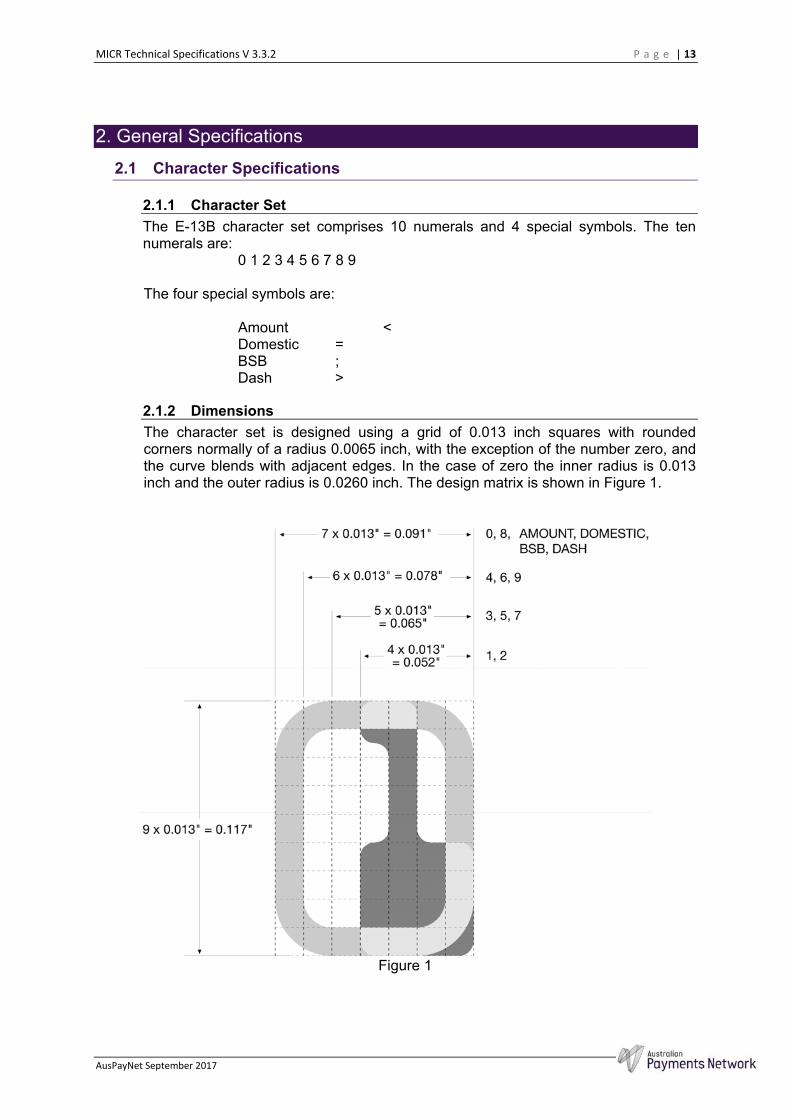
2.1.2 Dimensions
The character set is designed using a grid of 0.013 inch squares with rounded corners normally of a radius 0.0065 inch, with the exception of the number zero, and the curve blends with adjacent edges. In the case of zero the inner radius is 0.013 inch and the outer radius is 0.0260 inch. The design matrix is shown in Figure 1.
Figure 1
MICR Technical Specifications V 3.3.2 P a g e | 14
AusPayNet September 2017
Table 1
Character Height
Inch
Width
Inch
Width of Single Stroke Bars
Inch
0 0.117 0.091 0.013
1 0.117 0.052 0.013
2 0.117 0.052 0.013
3 0.117 0.065 0.013
4 0.117 0.078 0.013
5 0.117 0.065 0.013
6 0.117 0.078 0.013
7 0.117 0.065 0.013
8 0.117 0.0 91 0.013
9 0.117 0.078 0.013
"B 0.117 0.091 0.013
#C 0.091 0.091 0.013
!A 0.117 0.091 0.013
$D 0.052 0.091 0.013
The detailed outline of each character is shown in Appendix 1, with the tolerances and magnetic waveform as shown in Appendix 2, and both of which are discussed in subsequent sections.
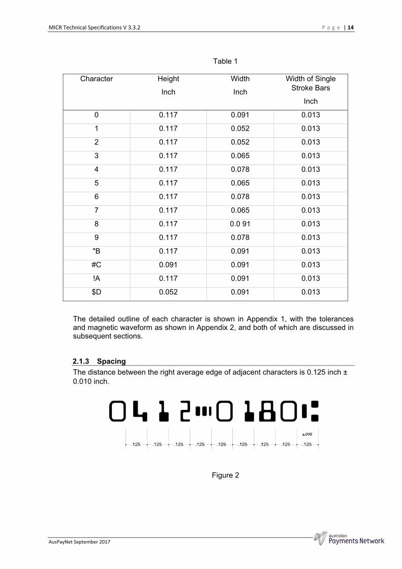
2.1.3 Spacing
The distance between the right average edge of adjacent characters is 0.125 inch ± 0.010 inch.
Figure 2
MICR Technical Specifications V 3.3.2 P a g e | 15
AusPayNet September 2017
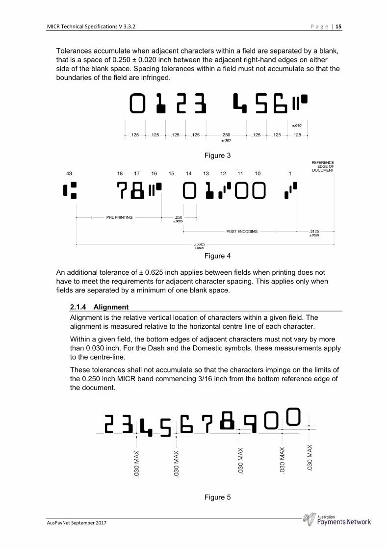
Tolerances accumulate when adjacent characters within a field are separated by a blank, that is a space of 0.250 ± 0.020 inch between the adjacent right-hand edges on either side of the blank space. Spacing tolerances within a field must not accumulate so that the boundaries of the field are infringed.
Figure 3
Figure 4
An additional tolerance of ± 0.625 inch applies between fields when printing does not have to meet the requirements for adjacent character spacing. This applies only when fields are separated by a minimum of one blank space.
2.1.4 Alignment
Alignment is the relative vertical location of characters within a given field. The alignment is measured relative to the horizontal centre line of each character.
Within a given field, the bottom edges of adjacent characters must not vary by more than 0.030 inch. For the Dash and the Domestic symbols, these measurements apply to the centre-line.
These tolerances shall not accumulate so that the characters impinge on the limits of the 0.250 inch MICR band commencing 3/16 inch from the bottom reference edge of the document.
Figure 5
MICR Technical Specifications V 3.3.2 P a g e | 16
AusPayNet September 2017
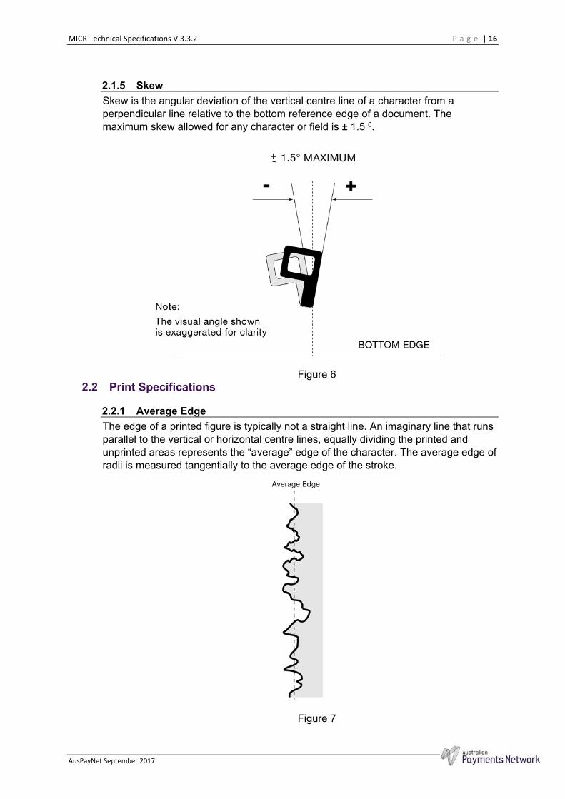
2.1.5 Skew
Skew is the angular deviation of the vertical centre line of a character from a perpendicular line relative to the bottom reference edge of a document. The maximum skew allowed for any character or field is ± 1.5 0.
Figure 6
2.2 Print Specifications
2.2.1 Average Edge
The edge of a printed figure is typically not a straight line. An imaginary line that runs parallel to the vertical or horizontal centre lines, equally dividing the printed and unprinted areas represents the “average” edge of the character. The average edge of radii is measured tangentially to the average edge of the stroke.
Figure 7
MICR Technical Specifications V 3.3.2 P a g e | 17
AusPayNet September 2017
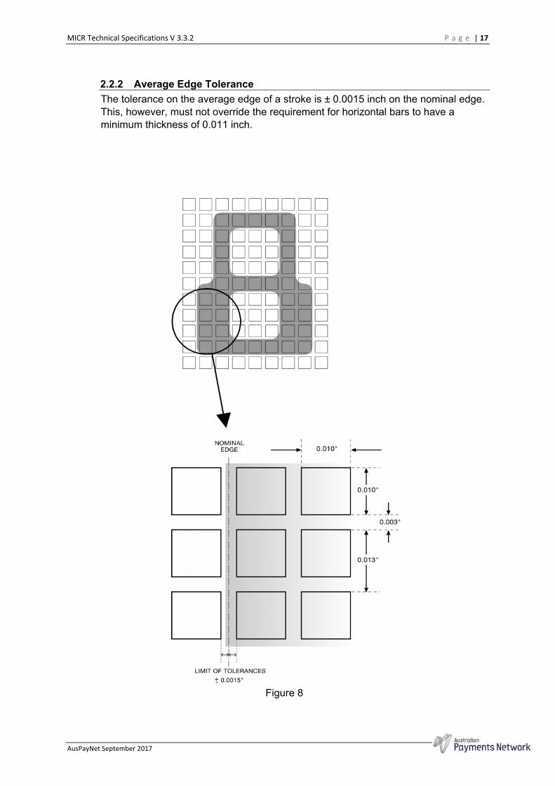
2.2.2 Average Edge Tolerance
The tolerance on the average edge of a stroke is ± 0.0015 inch on the nominal edge. This, however, must not override the requirement for horizontal bars to have a minimum thickness of 0.011 inch.
Figure 8
MICR Technical Specifications V 3.3.2 P a g e | 18
AusPayNet September 2017
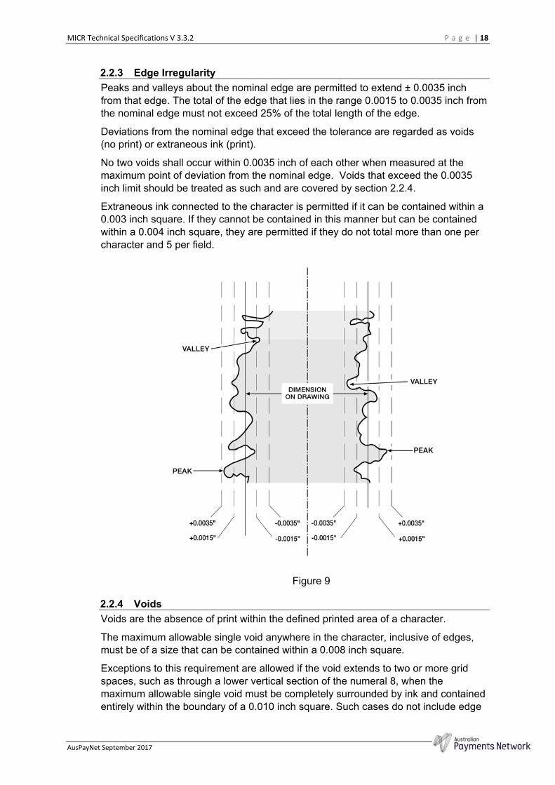
2.2.3 Edge Irregularity
Peaks and valleys about the nominal edge are permitted to extend ± 0.0035 inch from that edge. The total of the edge that lies in the range 0.0015 to 0.0035 inch from the nominal edge must not exceed 25% of the total length of the edge.
Deviations from the nominal edge that exceed the tolerance are regarded as voids (no print) or extraneous ink (print).
No two voids shall occur within 0.0035 inch of each other when measured at the maximum point of deviation from the nominal edge. Voids that exceed the 0.0035 inch limit should be treated as such and are covered by section 2.2.4.
Extraneous ink connected to the character is permitted if it can be contained within a 0.003 inch square. If they cannot be contained in this manner but can be contained within a 0.004 inch square, they are permitted if they do not total more than one per character and 5 per field.
Figure 9
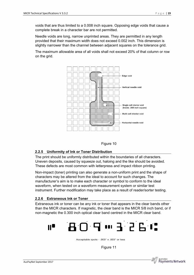
2.2.4 Voids
Voids are the absence of print within the defined printed area of a character.
The maximum allowable single void anywhere in the character, inclusive of edges, must be of a size that can be contained within a 0.008 inch square.
Exceptions to this requirement are allowed if the void extends to two or more grid spaces, such as through a lower vertical section of the numeral 8, when the maximum allowable single void must be completely surrounded by ink and contained entirely within the boundary of a 0.010 inch square. Such cases do not include edge
MICR Technical Specifications V 3.3.2 P a g e | 19
AusPayNet September 2017
voids that are thus limited to a 0.008 inch square. Opposing edge voids that cause a complete break in a character bar are not permitted.
Needle voids are long, narrow unprinted areas. They are permitted in any length provided that their maximum width does not exceed 0.002 inch. This dimension is slightly narrower than the channel between adjacent squares on the tolerance grid.
The maximum allowable area of all voids shall not exceed 20% of that column or row on the grid.
Figure 10
2.2.5 Uniformity of Ink or Toner Distribution
The print should be uniformly distributed within the boundaries of all characters. Uneven deposits, caused by squeeze out, haloing and the like should be avoided. These defects are most common with letterpress and impact ribbon printing.
Non-impact (toner) printing can also generate a non-uniform print and the shape of characters may be altered from the ideal to account for such changes. The manufacturer’s aim is to make each character or symbol to conform to the ideal waveform, when tested on a waveform measurement system or similar test instrument. Further modification may take place as a result of reader/sorter testing.
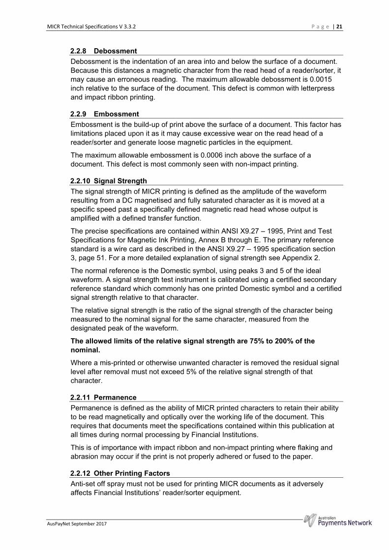
2.2.6 Extraneous Ink or Toner
Extraneous ink or toner can be any ink or toner that appears in the clear bands other than the MICR characters. If magnetic, the clear band is the MICR 5/8 inch band, or if non-magnetic the 0.300 inch optical clear band centred in the MICR clear band.
Figure 11

MICR Technical Specifications V 3.3.2 P a g e | 20
AusPayNet September 2017
On the front of the document, magnetic ink spots that can be contained in a 0.003 inch square may appear in any number. Larger spots that can be contained within a 0.004 inch square are only acceptable if they do not exceed one per character space and not exceed more than 5 per field.
Figure 12
Non-magnetic ink within the 0.300 inch optical clear band on the front of the document must be contained within a 0.008 inch diameter circle and no closer than 0.040 inch to each other or an E-13B character.
Figure 13
On the back of a document, spots of magnetic ink in the 5/8 inch MICR clear band that can be contained within a 0.006 inch square, are allowed in any number.
2.2.7 Clear Bands
The Print Contrast Signal (“PCS”) level of any printing in the MICR clear band other than MICR characters must be below 0.30. The MICR characters must have a PCS greater than 0.60. Borders with a PCS more than 0.60 must not intrude into the MICR clear band and must also conform to layout requirements of the Design Specifications for Cheques and Deposit Forms.
Amended, effective 19/05/08
Only the MICR characters are to be printed with magnetic ink. Printed perforations in magnetic ink or toner that may impinge on the clear band are not permitted.
The reverse side of the clear band must be clear of carboning. Carbonless coatings may only be used by arrangement with the relevant Financial Institution.
MICR Technical Specifications V 3.3.2 P a g e | 21
AusPayNet September 2017
2.2.8 Debossment
Debossment is the indentation of an area into and below the surface of a document. Because this distances a magnetic character from the read head of a reader/sorter, it may cause an erroneous reading. The maximum allowable debossment is 0.0015 inch relative to the surface of the document. This defect is common with letterpress and impact ribbon printing.
2.2.9 Embossment
Embossment is the build-up of print above the surface of a document. This factor has limitations placed upon it as it may cause excessive wear on the read head of a reader/sorter and generate loose magnetic particles in the equipment.
The maximum allowable embossment is 0.0006 inch above the surface of a document. This defect is most commonly seen with non-impact printing.
2.2.10 Signal Strength
The signal strength of MICR printing is defined as the amplitude of the waveform resulting from a DC magnetised and fully saturated character as it is moved at a specific speed past a specifically defined magnetic read head whose output is amplified with a defined transfer function.
The precise specifications are contained within ANSI X9.27 – 1995, Print and Test Specifications for Magnetic Ink Printing, Annex B through E. The primary reference standard is a wire card as described in the ANSI X9.27 – 1995 specification section 3, page 51. For a more detailed explanation of signal strength see Appendix 2.
The normal reference is the Domestic symbol, using peaks 3 and 5 of the ideal waveform. A signal strength test instrument is calibrated using a certified secondary reference standard which commonly has one printed Domestic symbol and a certified signal strength relative to that character.
The relative signal strength is the ratio of the signal strength of the character being measured to the nominal signal for the same character, measured from the designated peak of the waveform.
The allowed limits of the relative signal strength are 75% to 200% of the nominal.
Where a mis-printed or otherwise unwanted character is removed the residual signal level after removal must not exceed 5% of the relative signal strength of that character.
2.2.11 Permanence
Permanence is defined as the ability of MICR printed characters to retain their ability to be read magnetically and optically over the working life of the document. This requires that documents meet the specifications contained within this publication at all times during normal processing by Financial Institutions.
This is of importance with impact ribbon and non-impact printing where flaking and abrasion may occur if the print is not properly adhered or fused to the paper.
2.2.12 Other Printing Factors
Anti-set off spray must not be used for printing MICR documents as it adversely affects Financial Institutions’ reader/sorter equipment.
MICR Technical Specifications V 3.3.2 P a g e | 22
AusPayNet September 2017
The use of additives to facilitate the drying of magnetic ink should only be used after advice from the ink manufacturer, as such driers may affect the signal strength of the print.
2.3 Document Format Specifications
2.3.1 Size of Documents
The minimum and maximum dimensions of the document, excluding butts and other attachments, must be within the following limits:
Length 6 1/4 inch (159 mm) up to 8 1/4 inch (210 mm)
Height: 2 9/16" (64 mm) up to 3 2/3" (93 mm )
Amended, effective 13/09/11
2.3.2 Reference Edges
All dimensions are to be measured from the relevant reference edge. For horizontal measurements, this is the right-hand edge when viewed from the front of a document. Vertical measurements are similarly related to the bottom edge of a document.
The intersection of the reference edges must be a right angle.
2.3.3 MICR Clear Band
The MICR clear band is a horizontal band extending 5/8 inch from the bottom reference edge of a document. The band extends the full length of the document.
2.3.4 Optical Clear Band
The optical clear band is a rectangle 0.300 inch high located 0.015 inch above the bottom reference edge of the document and extends the full length of the document. It is totally contained within the MICR clear band.
2.3.5 Location within MICR Clear Band
The MICR codeline is to be printed so that the bottom edges of characters are ideally 0.24 inch from the bottom reference edge and must be wholly contained within the MICR Print band. The location and formatting of MICR characters within the codeline are outlined in section 3.
MICR Technical Specifications V 3.3.2 P a g e | 23
AusPayNet September 2017
3 MICR Code line specifications 3. MICR Code Line Specifications
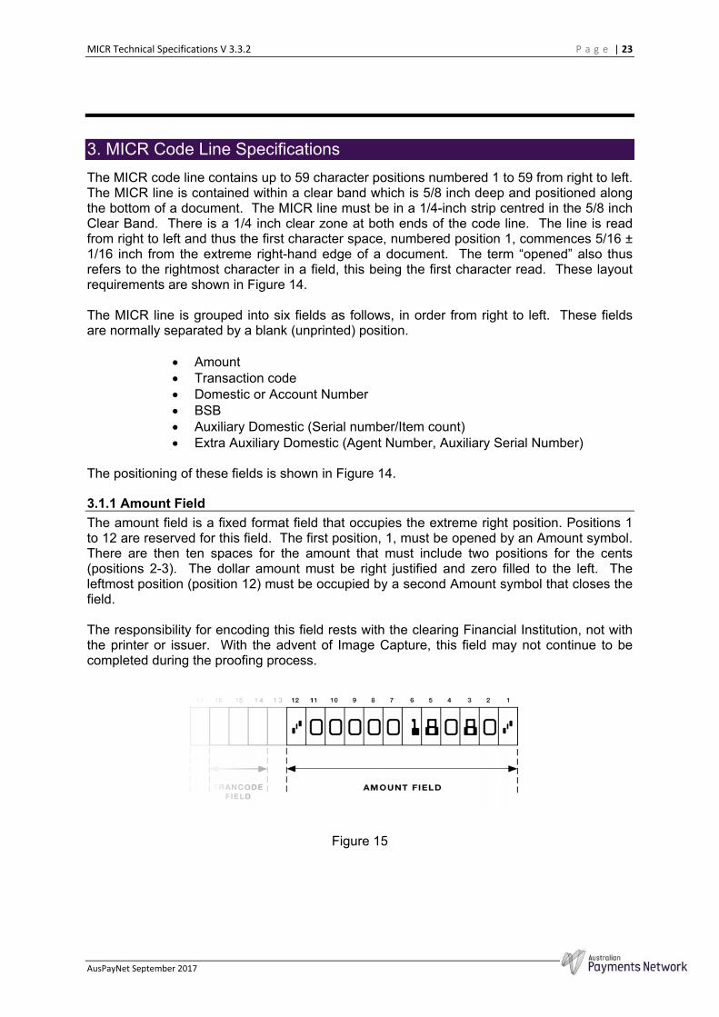
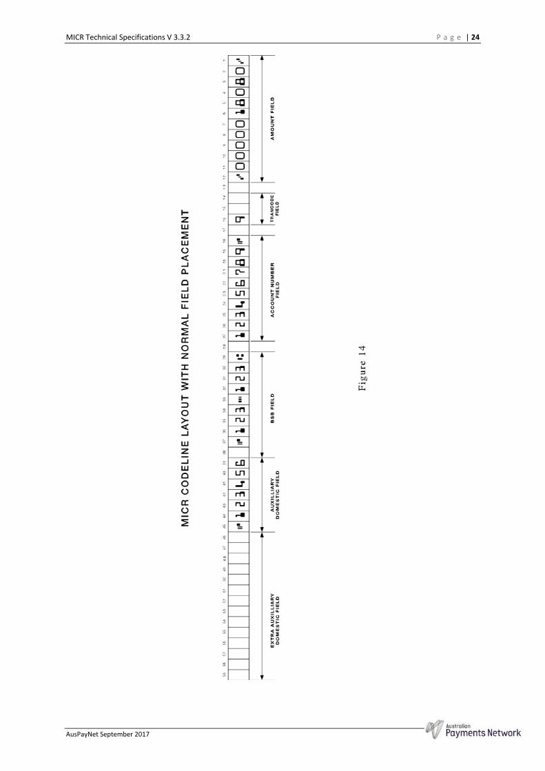
The MICR code line contains up to 59 character positions numbered 1 to 59 from right to left. The MICR line is contained within a clear band which is 5/8 inch deep and positioned along the bottom of a document. The MICR line must be in a 1/4-inch strip centred in the 5/8 inch Clear Band. There is a 1/4 inch clear zone at both ends of the code line. The line is read from right to left and thus the first character space, numbered position 1, commences 5/16 ± 1/16 inch from the extreme right-hand edge of a document. The term “opened” also thus refers to the rightmost character in a field, this being the first character read. These layout requirements are shown in Figure 14.
The MICR line is grouped into six fields as follows, in order from right to left. These fields are normally separated by a blank (unprinted) position.
Amount Transaction code Domestic or Account Number BSB Auxiliary Domestic (Serial number/Item count) Extra Auxiliary Domestic (Agent Number, Auxiliary Serial Number)
The positioning of these fields is shown in Figure 14.
3.1.1 Amount Field
The amount field is a fixed format field that occupies the extreme right position. Positions 1 to 12 are reserved for this field. The first position, 1, must be opened by an Amount symbol. There are then ten spaces for the amount that must include two positions for the cents (positions 2-3). The dollar amount must be right justified and zero filled to the left. The leftmost position (position 12) must be occupied by a second Amount symbol that closes the field.
The responsibility for encoding this field rests with the clearing Financial Institution, not with the printer or issuer. With the advent of Image Capture, this field may not continue to be completed during the proofing process.
Figure 15
MICR Technical Specifications V 3.3.2 P a g e | 24
AusPayNet September 2017
MICR Technical Specifications V 3.3.2 P a g e | 25
AusPayNet September 2017
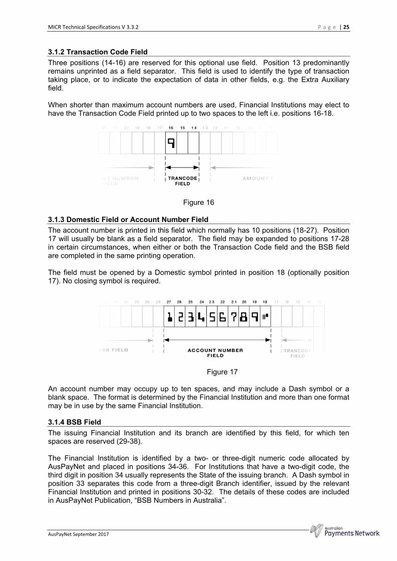
3.1.2 Transaction Code Field
Three positions (14-16) are reserved for this optional use field. Position 13 predominantly remains unprinted as a field separator. This field is used to identify the type of transaction taking place, or to indicate the expectation of data in other fields, e.g. the Extra Auxiliary field.
When shorter than maximum account numbers are used, Financial Institutions may elect to have the Transaction Code Field printed up to two spaces to the left i.e. positions 16-18.
Figure 16
3.1.3 Domestic Field or Account Number Field
The account number is printed in this field which normally has 10 positions (18-27). Position 17 will usually be blank as a field separator. The field may be expanded to positions 17-28 in certain circumstances, when either or both the Transaction Code field and the BSB field are completed in the same printing operation.
The field must be opened by a Domestic symbol printed in position 18 (optionally position 17). No closing symbol is required.
Figure 17
An account number may occupy up to ten spaces, and may include a Dash symbol or a blank space. The format is determined by the Financial Institution and more than one format may be in use by the same Financial Institution.
3.1.4 BSB Field
The issuing Financial Institution and its branch are identified by this field, for which ten spaces are reserved (29-38).
The Financial Institution is identified by a two- or three-digit numeric code allocated by AusPayNet and placed in positions 34-36. For Institutions that have a two-digit code, the third digit in position 34 usually represents the State of the issuing branch. A Dash symbol in position 33 separates this code from a three-digit Branch identifier, issued by the relevant Financial Institution and printed in positions 30-32. The details of these codes are included in AusPayNet Publication, “BSB Numbers in Australia”.

MICR Technical Specifications V 3.3.2 P a g e | 26
AusPayNet September 2017
The field is opened by a BSB symbol in position 29; this character is always used as the reference character for position. The closing character, a Domestic symbol, can be in positions 37 or 38. The use of position 38 leaves a space between the Domestic symbol and the rest of the field and has previously been permitted, however it should not be used on deposit forms as this conflicts with the requirements for item count post encoding (refer 3.1.6).
Figure 18
3.1.5 Auxiliary Domestic Field - Serial Number on Cheques
Seven spaces are normally reserved for this field, these being positions 39 - 45. The opening Domestic symbol for this field is the closing symbol of the BSB field. This factor can cause reader/sorter processing problems when these fields are not printed at the same time (due to mis-alignment).
The most common form of this field consists of six digits in positions 39 through 44 with a closing Domestic symbol in position 45. For any variation please consult the relevant Financial Institution.
The field may be expanded to 11 spaces, i.e. nine digits plus Dash plus Domestic symbol.
Note: Where the cheque serial number is greater than six digits the Transaction Code must be 9. The length of the form must be sufficient to ensure that the right-hand edge of the closing (left-most) symbol is not closer than 3/8 inch from the left or trailing edge of the form.
The rightmost digit of the serial number must be in position 39. A closing Domestic symbol must be printed in the leftmost position of the field, but not in a position greater than 49.
Figure 19
MICR Technical Specifications V 3.3.2 P a g e | 27
AusPayNet September 2017
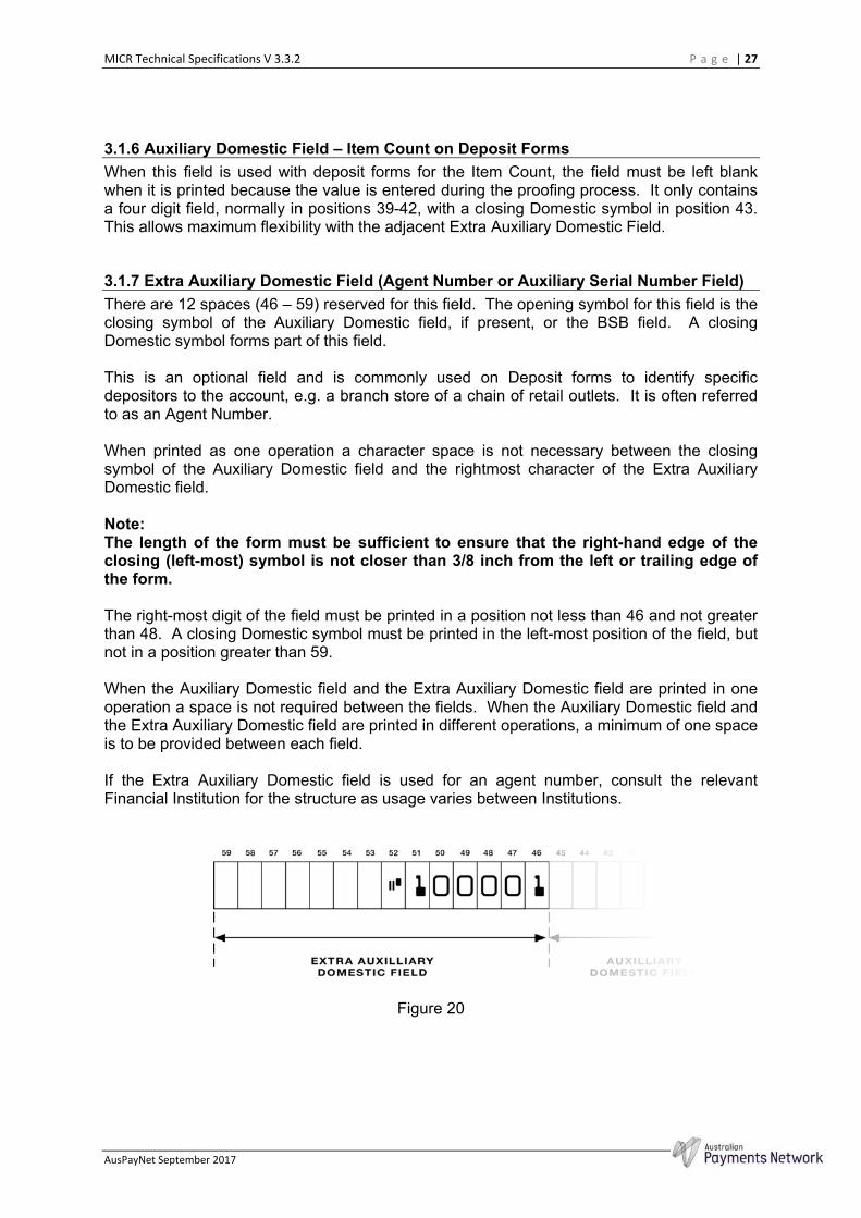
3.1.6 Auxiliary Domestic Field – Item Count on Deposit Forms
When this field is used with deposit forms for the Item Count, the field must be left blank when it is printed because the value is entered during the proofing process. It only contains a four digit field, normally in positions 39-42, with a closing Domestic symbol in position 43. This allows maximum flexibility with the adjacent Extra Auxiliary Domestic Field.
3.1.7 Extra Auxiliary Domestic Field (Agent Number or Auxiliary Serial Number Field)
There are 12 spaces (46 – 59) reserved for this field. The opening symbol for this field is the closing symbol of the Auxiliary Domestic field, if present, or the BSB field. A closing Domestic symbol forms part of this field.
This is an optional field and is commonly used on Deposit forms to identify specific depositors to the account, e.g. a branch store of a chain of retail outlets. It is often referred to as an Agent Number.
When printed as one operation a character space is not necessary between the closing symbol of the Auxiliary Domestic field and the rightmost character of the Extra Auxiliary Domestic field.
Note: The length of the form must be sufficient to ensure that the right-hand edge of the closing (left-most) symbol is not closer than 3/8 inch from the left or trailing edge of the form.
The right-most digit of the field must be printed in a position not less than 46 and not greater than 48. A closing Domestic symbol must be printed in the left-most position of the field, but not in a position greater than 59.
When the Auxiliary Domestic field and the Extra Auxiliary Domestic field are printed in one operation a space is not required between the fields. When the Auxiliary Domestic field and the Extra Auxiliary Domestic field are printed in different operations, a minimum of one space is to be provided between each field.
If the Extra Auxiliary Domestic field is used for an agent number, consult the relevant Financial Institution for the structure as usage varies between Institutions.
Figure 20
MICR Technical Specifications V 3.3.2 P a g e | 28
AusPayNet September 2017
4 MICR Printing Technologies 4. MICR Printing Technologies
A general description of the various technologies that are in use for printing MICR is provided in this section as guidance for those printing, or who may be considering printing MICR documents. An understanding of the capabilities and limitations of the various technologies available is important in equipment selection and establishing quality control procedures. The potential causes of generating out of specification MICR printing are outlined to assist in the production of good quality documents.
In all cases, it is essential to monitor the quality of printing with the appropriate equipment to ensure the process is correctly adjusted. Some processes, particularly conventional printing methods, require much greater attention than others. The level of care can only be assessed from experience and knowledge of the particular technology or machine used.
4.1 Conventional Printing Processes
4.1.1 Letterpress
Letterpress printing uses raised type that is covered with ink, which is then transferred directly to paper under pressure. This method was the original manner in which MICR was printed and the specifications for character shape, dimensions and print quality still largely reflect the characteristics of letterpress printing.
Lead type is not now common but if used it is important that the correct E-13B font is used and that the type be in good condition. Numbering boxes, likewise, must be correctly designed and free of damage or excessive wear. Lead type can only print static data whereas numbering boxes can print a combination of static and incremental data, plus mechanically generated check digit numbers.
Because of the nature of the process, the raised printing surface is particularly susceptible to debossment and ink spread. It is important to set type and numbering boxes evenly or part of the printing may be debossed and show excessive growth whilst another part may be poorly inked, giving a thin or broken up appearance.
Special care is required with the maintenance of numbering boxes and the manufacturer's recommendation for cleaning and oiling should be followed in detail. Over lubrication is to be avoided particularly on high-speed rotary presses as the oil may contaminate the face of the E-13B character with resultant loss of affinity for magnetic ink. The pre-inking of all characters on each sequential numbering wheel is necessary to ensure adequate ink coverage.
The best results are obtained by maintaining an ink film of even density over the entire typeface, that is free of voids, and with the least possible squeeze-out. Over inking results in excessive growth, filling in of characters, ragged edges and set-off on the back of following sheets. Conversely, under inking will result in under-size characters with voids and low signal strength. Impression and ink film thickness must be matched so that neither factor has to compensate for the faults of the other.
MICR Technical Specifications V 3.3.2 P a g e | 29
AusPayNet September 2017
4.1.1 Offset Lithography
The lithographic process can only be used for the printing of static MICR encoding. The original image is normally typeset, converted to a photographic image and then transferred to a printing plate. Modern processes are eliminating many of these steps, but the requirements for maintaining quality remain unchanged.
Photo-composing/typesetting devices must use the correct E-13B font and horizontal spacing between characters. If negatives are used, only reliable, stable based film and a properly compounded developer should be used. Because the ink will be magnetic, no guide marks are allowed within the clear band in which the MICR characters will appear. A final inspection of opaquing should be completed using a magnifier over the same clear band area to ensure that pinholes do not go undetected. There are no special requirements for the preparation of plates, other than normal maintenance of good quality control of the process.
For direct imaging processes, whether using paper, plastic or metal plates, the same requirements for care apply, that is, use of the correct font and character spacing, plus avoidance of sources of extraneous ink in the clear band.
Lithography is particularly sensitive to signal level, character dimensions and extraneous ink. As in letterpress, the aim in offset printing is to lay down a magnetic ink film of constant thickness. Over inking can cause image spread, extraneous ink, set off and distortion as well as difficulty in drying. Care must be taken to check the reverse of printed work for set off which is not permitted in the reverse of the 5/8 inch clear band. Conversely, under inking will cause thin characters, voids and low signal levels. The correct balance must also be maintained between the ink and dampening solution as an imbalance can cause emulsification and a lack of water will allow inking of non print areas, both resulting in extraneous ink. In addition, the offset blanket can cause slurring and double images if not sufficiently tightened.
4.1.2 Magnetic Ink
Magnetic inks are manufactured to contain iron oxide that is capable of being magnetised by the write heads of reader/sorters. Because the processes lay down differing ink film thicknesses, offset and letterpress magnetic inks contain differing proportions of iron oxide.
Because magnetic ink contains from 50% to 60% iron oxide, it behaves in a different manner to normal inks. Its higher viscosity requires constant agitation preferably using an ink fountain agitator. Magnetic inks also take longer to dry than normal inks and extra care has to be taken in early handling of the printed forms to avoid set off. The presence of iron oxide causes abrasive and chemical changes to press parts and thus greater attention is required to maintenance than is normal.
As magnetic ink does not run as consistently as normal inks, particularly on offset machines, output must be checked at regular intervals to see that the image is still sharp and smooth, and the signal level is correct.
4.2 Ribbon Encoding
Ribbon encoding involves the transfer of a magnetic coating from a plastic film carrier to paper using either mechanical force or heat. A number of obsolete typewriter-style transfer methods may still be in limited use but have not been described in this
MICR Technical Specifications V 3.3.2 P a g e | 30
AusPayNet September 2017
publication. Apart from the use of this method by cheque printers, it is commonly used in proof encoding machines for adding the amount field. The use of mechanical force leads to this method being also known as impact printing.
4.2.1 Drum Printers
Drum printers are used on their own to print MICR characters, or to supplement other impact or non-impact printing methods to provide totally variable data. The method uses a cylindrical drum, which has raised E-13B characters on its surface, rotating at a fixed speed. A bank of magnetically driven hammers is situated opposite this drum and selectively energised by a microprocessor. Between the drum and the hammer bank are the magnetic ribbon and the paper to be printed. A character is printed by a hammer impacting upon the ribbon and forcing the ribbon and paper against the selected MICR character on the drum, the impact transferring the ribbon material to the paper in the shape of the E-13B character. This method has proved capable of providing very consistent, high quality MICR printing if the equipment is correctly maintained.
4.2.2 Numbering Box Printers
The use of numbering boxes instead of a drum is an older and more basic method of ribbon encoding. In this case the raised typeface of the numbering box is normally forced against a ribbon onto paper travelling over an anvil. An alternative method moves the anvil against the numbering box. Various configurations of this equipment exist and their effectiveness is dependent on the amount of force used. Some equipment has limited force for the transfer and this can result in poor quality MICR due to incomplete transfer to the paper or flaking of the MICR characters during normal document handling.
4.2.3 Proof Encoder Printers
These are usually small, low speed, units with a single row of raised E-13B characters around a narrow drum. The drum is mounted on a rotating axle whose orientation is moved in response to keyboard strokes from the proof-machine operator. The drum presses a narrow ribbon against the document being processed, thus generating the required MICR characters. Because of the lightweight construction and heavy use, this process is often the cause of poor quality MICR encoding.
4.2.4 Thermal Ribbon Encoding
Thermal encoding has only been used on proof machines and the process is the same as that commonly used for generating bar codes except that the ribbon used contains a high level of iron oxide.
The thermal printhead is made up of a fine matrix of heating elements that can be selectively heated to create the shape of the required characters. This head is in contact with the ribbon and paper so that when the elements in the printhead are heated, the ribbon material is melted and transferred to the paper.
4.2.5 Ribbon Materials
The ribbon material is based on a thin plastic film carrier, usually Mylar, covered with a wax based coating. This coating contains sufficient iron oxide to make it magnetisable plus a number of resins and modifiers to ensure clean, even transfer of the coating when the appropriate force is applied. This coating requires more pressure to transfer to the paper than wet ink used in letterpress printing and depends more on physical force and paper surface attraction than penetration into the paper.
MICR Technical Specifications V 3.3.2 P a g e | 31
AusPayNet September 2017
Adequate adhesion of all encoded characters is essential to prevent abrasion during processing or fraudulent alteration. This is best obtained by the use of high impact equipment to ensure the characters become firmly attached to the fibrous surface of the paper. This is sometimes augmented by a fusion process using high-intensity light from Xenon lamps.
Other problems that can arise with this technology are filling in of characters and extraneous ink transferring from the ribbon due to an unduly soft ribbon composition. Conversely, a dry ribbon may result in partial transfer of the ribbon, creating voids. Excessive force may lead to debossment but this is preferable to the use of lower impact forces resulting in flaking of the MICR characters during normal document handling.
Type defects such as nicks, low spots, and rounded edges on the drum or non-uniform hammer or anvil surfaces can also cause voids or ragged edges on the MICR characters.
It is most important that the care, storage and shelf life instructions provided by MICR ribbon manufacturers are always followed. Prolonged exposure of ribbons to high temperatures and humidity can reduce the ribbon's life and impair the print quality. Rough handling causes ribbon coating transfer to the underside of the ribbons thus destroying their effectiveness.
It is imperative to ensure that the ribbon is a MICR ribbon by testing each batch to ensure that it meets signal strength requirements.
4.3 Non-impact MICR printing
The term non-impact is used in this context to differentiate this group of technologies from ribbon encoding which requires some form of mechanical force to transfer material from a ribbon to the paper form. The term embraces, but is not limited to such technologies as Laser, LED, Electron Beam Imaging and Magnetography. These technologies all have in common the use of a dry powder, or MICR toner, which is selectively transferred to paper to form an image. This toner contains iron oxide in sufficient quantity to make the print magnetisable to the required level to meet the signal level requirements.
The character shape and dimensions may vary slightly from the ideal illustrated within this Standard as toner is deposited in a different manner from ink or ribbon, but only to the extent of the tolerances specified for each of the fourteen E-13B MICR characters (refer to Appendix 2). This has required considerable work to optimise the character dimensions to gain the best result over the range of reader/sorters in use. Users must not change the E-13B font supplied with the system, or alter it in any way, as this will invalidate any guarantee or accreditation that comes with the system.
If choosing to in-fill cheque documents using a non-impact method it is suggested that a paper with toner enhanced, or frangible toner enhanced, features be considered. Consult with your security printer or refer to the AusPayNet Paper Register for suitable paper stocks.
Amended, effective 19/05/08

MICR Technical Specifications V 3.3.2 P a g e | 32
AusPayNet September 2017
4.3.1 Accreditation of MICR Printing Systems
To protect the efficiency of the clearing system, a process of accreditation of MICR printing systems has been adopted. This was necessary because of the large number of new high-volume non-impact MICR printers that are being sold in Australia. The large volumes of MICR documents that these systems can potentially supply could cause adverse effects on the clearing system if the MICR is not of an acceptable standard.
The accreditation process has been effective since January 1, 1998 and is detailed in Appendix 3 of this publication. The procedures define a “printing system” as a means of printing technology that is claimed to be suitable for producing MICR documents and includes the print engine, operating system, page description language (PDL) magnetic toner and the E-13B font. It usually covers all printers with increasing levels of testing applied relative to the system’s potential productivity.
Accreditation indicates that a Printing System, when operated in accordance with the Applicant's specifications, is capable of producing acceptable MICR encoding and has passed tests for accreditation of MICR Printing Systems as detailed in Appendix 3 of this publication. AusPayNet maintains a Register of accredited MICR Printing Systems and will provide information on these systems to any interested party (refer Appendix 3, section 1.6.).
However, due to manufacturing and/or operating variances, the Register is not a guarantee that an individual Printing System will produce acceptable results. The inclusion of a Printing System on the Register is not an endorsement by AusPayNet. The Register lists Printing Systems that have been submitted to AusPayNet for testing and found at the time of testing to have met the requirements set out in Appendix 3 of this publication.
Amended, effective 22/03/06
4.3.2 Security
Because of the comparative ease of operation of many non-impact MICR printing systems, especially desktop units, and as they are often set up to print value cheques there is a need to guard against their improper use. It is recommended that some or all of the following security precautions be used with non-impact MICR printing systems, the selection being made on a judgement of the element of risk:
System keylock to prevent unauthorised use Access control via Personal Identification Number or multiple level
passwords Encryption of signatures and/or E-13B font on a removable printer
cartridge which can be stored securely An audit trail held in non-volatile memory to record the details of
every cheque printing transaction In addition, care must be taken with the storage and use of pre-printed cheque stock where audit records should be kept to account of its use for authorised cheque issue, samples for MICR quality and spoilt cheques, together with a record of any stock destroyed for whatever purpose.
4.3.3 Print Quality
Under magnification, it can be seen that images are made up of a series of fine dots that create a continuous image when viewed by the naked eye. The size of these
MICR Technical Specifications V 3.3.2 P a g e | 33
AusPayNet September 2017
dots determines print quality and is known as the print resolution. This is described in terms of dots per inch (dpi) and applies both across and along the direction of paper travel. If expressed as a single value, the dpi value applies in both directions. If two values are quoted, the resolution varies by direction and the first figure quoted is the resolution across the paper path.
When comparing print quality from different technologies, the resolution can be misleading and the method of dot formation affects its appearance. It is thus best to make a judgement on the basis of printed samples.
4.3.4 Software
The software application that is used to position data on a page is known as the Page Description Language (PDL). Extreme caution needs to be taken when selecting a PDL to ensure that it can meet the character spacing requirements outlined in this publication in a predictable manner.
4.3.5 MICR Toner or Dry Ink
MICR Toner is manufactured from carbon black, iron oxide and resins. The formulations are specifically developed for each print engine and their properties are critical to successful MICR printing.
The iron oxide used is in the form of the mineral magnetite and is capable of being magnetised by a reader/sorter write head to a suitable level to be interpreted by the magnetic read head. The mineral occurs in two crystalline forms, cubic and needle-like. The latter form is favoured for MICR toner as it retains magnetism better than the cubic form. Certain technologies however require the cubic form to be used and have had to undergo considerably more development to obtain a suitable toner. It is essential that only MICR toner, as opposed to normal toner, is used for printing E-13B characters and printing systems that are designed to detect or accept only specifically designed MICR toner containers. This avoids potential problems with the use of non-MICR toner, and those systems that do not have this feature should be treated with caution.
A further desirable feature for high-volume printing is a self-monitoring print density facility that will ensure stable signal strength of the printer.
4.3.6 MICR Toner Adhesion Inserted, effective 22/03/06
Non-impact MICR printing must have toner adhesion that gives permanence (refer 2.2.11) to a level acceptable to the issuing Financial Institution and is capable of passing the Toner Adhesion Test specified in Section 1.5.2.4 of Appendix 3.
4.3.7 Storage of Paper for MICR Printing and the Effects of Moisture Inserted, effective 22/03/06
If MICR is being printed by laser printer (or other similar non-impact printing technology) then:
the moisture content of the paper will affect the level of toner adhesion
and thus permanence (refer 4.3.6); printing on paper with moisture content above 5.5% will have reduced
toner adhesion, which may mean that the MICR printing does not have an acceptable level of permanence;
maximum toner adhesion and permanence is achieved when the moisture content of paper is maintained during all stages of production at
MICR Technical Specifications V 3.3.2 P a g e | 34
AusPayNet September 2017
4.5 – 5.5%; and therefore, paper should be stored in a moisture proof wrapper at all times
prior to MICR printing, and sufficient time allowed for conditioning of the stock if it is moved between environments prior to MICR printing. Paper will gain or lose moisture depending on the relative humidity of the air if it is not kept in a moisture proof wrapper prior to MICR printing.
4.4 Non-impact MICR Printing Technologies
4.4.1 Laser Printers
Laser printers are based on the electrophotographic process developed by the Haloid Corporation (later Xerox Corporation) of Rochester, New York in the 1950s.
The key component is a photoreceptor drum or belt which has a uniform electrostatic charge created on its surface by a corotron. The charge is then selectively discharged by exposing the charged photoreceptor to a light source, in this case a laser beam directed at the surface by a rotating mirror. The data is transmitted by a stream of commands that rapidly turn the laser beam on and off. The image is generated by the development sub-system in which oppositely charged toner particles are attracted to the photoreceptor. Non-imaged areas repel these particles; thus, the drum is selectively coated to create the required image.
The image is transferred to paper by bringing the paper into contact with the photoreceptor. At this stage the paper is electrostatically charged in a manner that induces the toner to transfer from the photoreceptor to the paper. Passing through a heated nip roller fuses the image thus created, the nip normally being lubricated with a fine coating of silicone oil.
The discharged photoreceptor requires cleaning prior to re-imaging. This is achieved by use of a cleaner corotron that loosens them from the drum surface plus a brush to remove residual toner particles.
There are various arrangements of these basic components and the smaller desktop units have much simpler systems to reduce their cost.
For production size machines, Xerox Corporation is the major manufacturer of laser printers and is currently producing a 600 dpi, 180 ppm printers as well as a number of smaller printers in the range 40 to 90 ppm.
4.4.2 LED Printers
In this type of printer, a Light-Emitting Diode (LED) replaces the laser beam as the means for transmitting data. In most other aspects, this technology can be considered a special form of laser printing. The LED diodes are constructed as an array, known as a printbar, of very fine points that emit high-intensity light. Each diode is individually switched to control data transmission to the photoreceptor.
The major proponent of LED technology is Océ Printing Systems that manufactures a range of continuous MICR printers ranging in speed from 250 to 450 ppm and have multiple resolutions of 300 and 600 dpi in the same machine.
4.4.3 Electron Beam Imaging
Electron Beam Imaging, formally known as Ion Deposition, is mechanically simpler than Laser or LED printing. A rigid drum coated with a dielectric surface replaces the photoreceptor drum. The write head, is known as a print cartridge, and has a series
MICR Technical Specifications V 3.3.2 P a g e | 35
AusPayNet September 2017
of very small holes from which electrons are expelled towards the imaging drum. Each hole is individually controlled to create the data stream. The electrons charge the drum that then selectively attracts toner. The toner is transferred to paper using very high pressure. The toner is then (optionally) fused using a Xenon lamp that emits very high intensity light to melt the toner. The toner that is not transferred to the paper is scraped from the drum with a doctor blade and the residual electrical charge removed by an erase rod before the printing process recommences.
This technology has been developed by Delphax Systems, a Division of Xerox Corporation. The print tends to be more black than that from laser or LED systems and the dots are more diffused. The toner has required considerable development to achieve a satisfactory level for MICR printing. Printers are manufactured with 300 and 600 dpi resolutions and current models run at 300 ppm upwards.
In a more recent development of this technology, Delphax has designed a new print engine known as the “Gemini”. This is incorporated into CheckTechnology Corporation’s “Imaggia” printer for high-volume cheque printing. This engine uses a flexible image belt that is charged by the print cartridge. Toner is attracted from the toner hopper to the charged areas of the image belt. This is then passed to a heated transfer belt where the toner particles become molten before being finally transferred to pre-heated paper. As the image belt completely transfers toner to the transfer belt, only the latter needs some cleaning.
The CheckTechnology Imaggia printer has a resolution of 600 dpi and produces 220 A4 ppm. The print quality is significantly better than those from the earlier EBI engine.
4.4.4 Magnetography
The Magnetographic process is used primarily by Nipson Printing Systems and differs from the other processes by replacing photosensitive or dielectric imaging surfaces with a more robust magnetic drum. The drum is aluminium based with a series of magnetisable coatings. This surface is selectively magnetised using a high-density multitrack head and these magnetised areas attract toner particles. A brush prior to the transfer stage removes excess toner not bound to the drum. The bound toner is transferred by pressure to the paper and then fused with a xenon lamp. A strong magnet then erases the magnetised areas of the drum, and any residual toner removed from the surface before repeating the imaging sequence.
The current technology is at 480 dpi and gives a darker black, more diffused print than a laser at the same resolution.
4.4.5 Desk-top laser printers
Low volume, desk-top MICR printers are now commonly available but care needs to be taken in selecting such printers to ensure that they consistently meet the specifications detailed in this Publication.
The particular areas of concern are the MICR toner, its adhesion to the document and the E-13B font employed. Unless the printer specifically has a device to prevent non-MICR toner being used, there is potential for the different types of toners to be interchanged, with the resultant documents not meeting the signal strength standards. Likewise unless the E-13B font is of a fixed pitch, the size and spacing can be incorrect.

MICR Technical Specifications V 3.3.2 P a g e | 36
AusPayNet September 2017
Because of their low output, these printers are not invariably required to be accredited. Their incorrect use can however cause considerable problems in the clearing system and Quality Assurance procedures and sampling requirements outlined in section 6 must be observed.
MICR Technical Specifications V 3.3.2 P a g e | 37
AusPayNet September 2017
5 Reader/Sorter Operations
5.1 Recognition Technology
There are two main methods of recognising MICR characters that relate to how the machines magnetise characters and then interpret the resultant electrical signal. These are known as waveform and matrix read technologies. The magnetic recognition technology is also supplemented with Optical Character Recognition (OCR) on some machines. More recently Imaging and Intelligent Character Recognition (ICR) functions have become available. These latter functions remove much of the work carried out by proof-machine operators as the written or printed amount can be interpreted and recorded electronically instead of being entered by keyboard then MICR encoded on the document.
5.1.1 Waveform Readers
The MICR line is magnetised by passing over a write head and then read by moving past a magnetic read head that generates a very small electrical signal. The normal process uses the rate of change in this signal to generate a pattern that is unique for each character or symbol, this is the typical waveform image shown in this publication. An alternative method is to use the integrated waveform where the image is quite different, with no negative peaks.
The signals are captured, amplified and processed through special electronic circuitry to interpret and identify the characters. These systems can operate at very high speeds, up to 1,000 documents per minute. There is some variation between systems for the write heads but the read heads are all very similar, as they must conform to the ANSI Standards. The major differences are in the recognition methods, NCR, BancTec and some medium speed IBM machines use the integrated waveform whilst Unisys machines may use a derivative waveform method that is unique to Unisys. It should be noted that the algorithms used for interpretation of patterns and read/write head technology used for identification of MICR characters may vary from model to model within a manufacturer’s range.
The waveform method uses wide heads to cover the whole MICR band and as such have the ability to read at a distance from the head’s surface. This makes these machines tolerant of debossment or embossment of characters.
5.1.2 Matrix Readers
The matrix head method for MICR recognition was developed in the 1960s by Burroughs (now Unisys) and IBM. It is a more complex and expensive technology than the waveform method and has thus been used only on the higher speed machines. It has been adopted because it gives lower reject rates than waveform machines. The machines that currently use this technology are the IBM 3890 series and the Unisys DP1800 series of reader/sorters.
A high frequency AC write system magnetises the characters in a manner that breaks them up into individual slices, each with their own N-S poles. The read head has 30 mini-heads oriented at right angles to the slices generated by the write head. This process provides a magnetic bit matrix showing the presence or absence of magnetic material in each matrix cell. Electronic techniques allow for movement of the matrix pattern to optimise identification of characters.
MICR Technical Specifications V 3.3.2 P a g e | 38
AusPayNet September 2017
Because the read and write heads are very small, the MICR code line must be kept in very close contact with the matrix head for reliable reading. This makes the technology susceptible to over-debossment, where it may not read the characters. Conversely, embossed images may cause wear to the head and the MICR codeline. To overcome this, IBM uses a thin non-magnetic film between the document and the read head. This moves slowly across the head and removes any contamination, which could interfere with the reading capabilities of the machine.
5.2 Reader/Sorters
A reader/sorter is a mechanical document processor for reading MICR lines, interpreting and validating code lines and separating the documents into groups. The capability has also been added to make an image of the document for storage and interpretation of the value. This “Image Capture” capability will reduce the reliance on mechanical means for sorting, exchanging and storage of physical documents, as these functions are capable of being performed electronically.
5.2.1 Low Speed Reader/ Sorters and Proof Machines
A large range of lower speed reader/sorters is in use, largely for proof encoding and remittance processing purposes. These machines are usually manually loaded with the document being positioned for an operator to read the value of the document, which they then key enter. This value is then MICR encoded onto the document with a small impact ribbon printer and forward to one of a limited number of sort pockets.
The proof encoding process is being replaced by Image Capture and Intelligent Character Recognition technology, whereby the document’s image is stored and the written or printed value is interpreted and stored with the image. The data in the MICR line is still captured magnetically and stored with the image data ready for further electronic processing. The main tasks of the operator are to load the machine and interpret any amounts that the software cannot read with confidence.
5.2.2 High Speed Reader/Sorters
These machines are capable of processing over 1,500 six-inch documents per minute and are typically used in the processing centers of large Financial Institutions. Those in current use are the IBM 3890 series and the Unisys DP1800 series; plus the BancTec models 5500 and 5300 that are slightly slower speed machines.
These machines are typified by the large number of pockets that are used for sorting and several passes are made to initially capture data and then to sort documents into the required order for exchange and storage. The large number of passes used for this processing are the reason for many of the specifications relating to paper and print quality.
With a trend to electronic interchanges and Image Capture of documents, the number of passes through these machines will reduce.
5.2.3 Image Machines
Imaging capabilities can be added to many existing reader/sorters as an added function but in many cases, older equipment is being replaced with fully functional new processing equipment.
MICR Technical Specifications V 3.3.2 P a g e | 39
AusPayNet September 2017
The document is illuminated with a powerful light source and the image of both sides can be recorded with a digital camera. The image may be captured at 256 grey-levels and stored in a number of formats, depending on the use to be made of the image. For simple retention of the critical information, a high-contrast compressed image will retain sufficient data for ICR. The ICR process can interpret to a high degree of reliability the written or printed value of the amount of a document. If confirmation of difficult to interpret characters is required, the image can be displayed on a screen for operator intervention. This is the initial purpose of most Image installations. Exchange of data on transactions is increasingly being carried out electronically and the exchange of paper documents being mainly for storage.
Further progress is dependent on the acceptance of the use of electronic images in business and for record retention purposes. This will allow processing, exchange and retention to be electronically based. For such purposes, better quality images will be retained and the size of the file will become critical. Financial Institutions will thus place greater emphasis on document design that is aimed at minimising the size of the file of the document’s image.
MICR Technical Specifications V 3.3.2 P a g e | 40
AusPayNet September 2017
6 Paper for MICR encoded documents
Paper used to produce MICR encoded documents shall conform to the following specifications. These specifications supersede AS 2277 – 1994 (Australian Standard – Paper for MICR Encoded Documents).
Manufacturers and suppliers of such paper may apply to have their product(s) listed on the AusPayNet Paper Register in the manner described below. This will enable AusPayNet to advise APCS Framework Participants, Printers and other interested bodies of papers that conform to these specifications.
Samples tested for the AusPayNet Paper Register shall be conditioned according to AS 1301, P414m and samples taken according to AS 1301,P417s.
This specification includes details of security features as described in section 6 of this Publication.
6.1 AusPayNet Paper Register
The AusPayNet Paper Register lists paper grades that conform to this specification. Manufacturers and suppliers who wish to have their product(s) listed on the AusPayNet Paper Register should contact AusPayNet for the application form. The application form will request details of the paper’s properties in reference to the specifications and test methods outlined below.
Details of the laboratory test results would need to be supplied showing the numeric values and normal range that is achieved in the manufacture of the paper grade specified. In addition, where the paper is watermarked, sensitised or special inclusions are used for security purposes, samples of the typical product shall be provided as required by the application form.
The application shall be reviewed by AusPayNet and, if the paper meets the specifications, the paper shall be placed on the AusPayNet Paper Register.
Once on the AusPayNet Paper Register, the paper shall be reviewed annually. AusPayNet shall contact the applicant to provide updated information. The information shall be reviewed in the same manner as a new application. If information is not provided within a reasonable time, the paper grade shall be removed from the AusPayNet Paper Register.
6.2 General properties
6.2.1 Surface
The surface shall be smooth with no major irregularities and free of dust, lint or dirt.
The paper shall be sized to facilitate rapid ink drying.
6.2.2 Constitution
The fibre finish shall be 100% chemical bleached fibre. The filler shall be chemically neutral and non-abrasive. No magnetisable particles are permitted to be present, as
MICR Technical Specifications V 3.3.2 P a g e | 41
AusPayNet September 2017
these will interfere with the MICR readings.
6.2.3 Coatings
Other than for carbonless coatings, where special conditions apply, any coatings should not adversely affect the writing and printing quality of the paper, and must be free of abrasive materials. Special coatings that, for example enhance drying of MICR ink or improve toner adhesion, are permitted as long as they conform to these specifications.
6.2.4 Permanent Paper
Paper should conform to Standards for Permanent Paper, AS 4003 –1996 or ISO 9706:1994. This will require the use of alkaline size.
6.2.5 Other
Paper shall be free of curl and suitable for the following printing processes: i) Letterpress, Wet and Dry Offset printing for multiple colours ii) Web press and Sheet fed printing iii) MICR Encoding by the above methods plus impact (ribbon) and non-
impact (toner) printing
6.3 Security features
6.3.1 Watermarked paper
The features of the watermark have to be clearly visible when backlit with normal office levels of illumination. For inclusion in the AusPayNet Paper Register, the design as agreed between the contracting parties and signed by the mill as representative of their product, must be supplied to AusPayNet for review and inclusion in the AusPayNet Paper Register .
The watermark should not interfere with MICR encoding and samples should be supplied together with the application for inclusion in the AusPayNet Paper Register.
6.3.2 Sensitised Paper
Paper that is sensitised for security purposes shall contain chemical agents sensitive to acid, alkali, bleach and solvents. The properties of the paper shall conform to the Specification after being treated to incorporate these chemicals.
The paper shall show a clearly visible reaction after 1 minute when a small drop (ca. 0.5 ml) of a specified reagent is placed on the paper.
The list of chemical reagents to which the paper should react will be supplied to mills in confidence by AusPayNet. The list shall comprise of about 20 reagents and may be revised by AusPayNet from time to time in response to changing security needs.
For inclusion in the AusPayNet Paper Register, a sample showing reactions to the listed chemicals and signed by the mill as representative of their product, must be supplied to AusPayNet for review and inclusion in the Paper Register.
6.3.3 Security inclusions
The inclusion of fluorescent materials for security purposes, such as fibres or planchettes, must not affect the processing properties of the paper either during the
MICR Technical Specifications V 3.3.2 P a g e | 42
AusPayNet September 2017
printing process or the clearing process. The nature of such inclusions should be specified for inclusion in the AusPayNet Paper Register.
6.4 Carboning
6.4.1 Carbonless paper
The paper used for a carbonless stock must conform to these specifications before coating. The amount of coating used should be such that the higher limits of grammage and thickness are not exceeded.
Before using any carbonless coated papers, the relevant Financial Institution should be consulted to ensure the stock is compatible with their processing equipment. The Financial Institution may require testing to take place before approving the use of such stock.
6.4.2 Carbon coatings
All over carbon coating is not permitted.
Spot carboning on the reverse is strongly discouraged but, if used, must avoid areas used by Financial Institutions clearing equipment and transport systems.
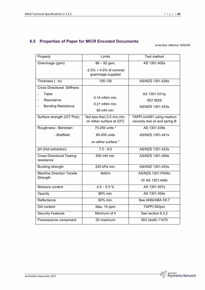
MICR Technical Specifications V 3.3.2 P a g e | 43
AusPayNet September 2017
6.5 Properties of Paper for MICR Encoded Documents Amended, effective 19/05/08
Property Limits Test method
Grammage (gsm) 86 – 92 gsm,
-2.5% + 4.0% of nominal grammage supplied
AS 1301.405s
Thickness ( m) 105-130 AS/NZS 1301.426s
Cross Directional Stiffness
- Taber
- Resonance
- Bending Resistance
0.14 mNm min.
0.21 mNm min.
60 mN min.
AS 1301.431rp
ISO 5629
AS/NZS 1301.453s
Surface strength (IGT Pick) Not less than 2.0 m/s min. on either surface at 230C
TAPPI.Um591 using medium viscosity test oil and spring B
Roughness:- Bendsten
- Sheffield
75-250 units *
80-200 units
on either surface *
AS 1301.439s
AS/NZS 1301.441s
pH (Hot extraction) 7.5 - 9.0 AS/NZS 1301.422s
Cross Directional Tearing resistance
500 mN min. AS/NZS 1301.400s
Bursting strength 220 kPa min. AS/ANZ 1301.403s
Machine Direction Tensile Strength
4kN/m AS/NZS 1301.P404s
Or AS 1301.448s
Moisture content 4.5 – 5.5 % AS 1301.457s
Opacity 86% min. AS 1301.454s
Reflectance 60% min. See ANSI/ABA X9.7
Dirt content Max. 10 ppm TAPPI.563pm
Security Features Minimum of 4 See section 6.3.2
Fluorescence component 20 maximum ISO (draft) 11475
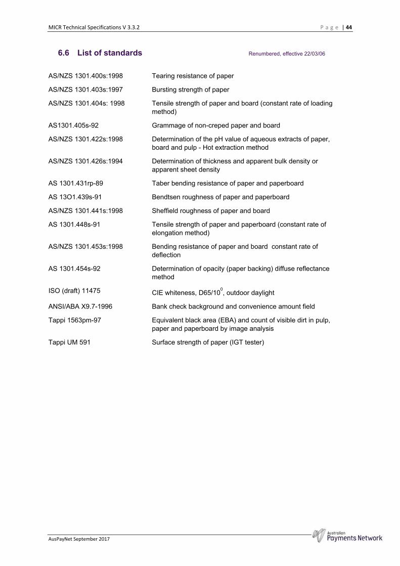
MICR Technical Specifications V 3.3.2 P a g e | 44
AusPayNet September 2017
6.6 List of standards Renumbered, effective 22/03/06
AS/NZS 1301.400s:1998 Tearing resistance of paper
AS/NZS 1301.403s:1997 Bursting strength of paper
AS/NZS 1301.404s: 1998 Tensile strength of paper and board (constant rate of loading method)
AS1301.405s-92 Grammage of non-creped paper and board
AS/NZS 1301.422s:1998 Determination of the pH value of aqueous extracts of paper, board and pulp - Hot extraction method
AS/NZS 1301.426s:1994 Determination of thickness and apparent bulk density or apparent sheet density
AS 1301.431rp-89 Taber bending resistance of paper and paperboard
AS 13O1.439s-91 Bendtsen roughness of paper and paperboard
AS/NZS 1301.441s:1998 Sheffield roughness of paper and board
AS 1301.448s-91 Tensile strength of paper and paperboard (constant rate of elongation method)
AS/NZS 1301.453s:1998 Bending resistance of paper and board constant rate of deflection
AS 1301.454s-92 Determination of opacity (paper backing) diffuse reflectance method
ISO (draft) 11475 CIE whiteness, D65/100, outdoor daylight
ANSI/ABA X9.7-1996 Bank check background and convenience amount field
Tappi 1563pm-97 Equivalent black area (EBA) and count of visible dirt in pulp, paper and paperboard by image analysis
Tappi UM 591 Surface strength of paper (IGT tester)

MICR Technical Specifications V 3.3.2 P a g e | 45
AusPayNet September 2017
7 Quality Control of MICR
The quality of MICR encoded documents must be maintained at a high level to ensure the efficiency of the clearing system. MICR quality assurance procedures are intended to ensure that the information printed on a document is correct, in the proper positions and meets the requirements for print quality as detailed in this Publication. It is also important to note that the specifications are based on optical and magnetic characteristics. Whilst a Financial Institution may track its performance using the reject rate from its reader/sorters this is not, in isolation, an appropriate method to quality check MICR encoded documents. As outlined earlier, there are a number of technologies employed to manufacture reader/sorters, and no one of these can be considered characteristic of all reader/sorters. The specifications thus apply equally to the documents and the reader/sorters.
7.1 Accreditation of MICR Printing Technology An accreditation process for evaluating MICR Printing Technology was introduced in January 1998 and is set out in Appendix 3 of this publication. The purpose of this accreditation is to protect the clearing system from being presented with large numbers of poor quality MICR documents.
Accreditation indicates that a Printing System, when operated in accordance with the manufacturer’s specifications, is capable of producing acceptable MICR encoding and has passed the tests outlined in Appendix 3 of this publication. Because of operating and manufacturing variances, accreditation is not a guarantee that a Printing System will produce acceptable results. Hence the quality assurance procedures detailed in this section must be followed to ensure continuing conformance.
7.2 Evaluation Samples For commercial cut sheet and continuous MICR printing, evaluation samples must be supplied to the issuing Financial Institution for every print run of MICR encoded documents unless a contractual arrangement is in place between a Financial Institution and a Printer. The following sampling plan must be followed for printing cheques and deposit forms, and regardless of the printing technology used.
One sample form at the start of the run One sample every 5,000 to 6,000 forms One sample at the completion of the run
When printing is in a continuous form, this plan can be modified to submit the intermediate samples at reel or pack changes, or other natural break in production. For jobs in excess of 100, 000 forms, Printers should consult the issuing Financial Institution for their requirements that may vary from those outlined above.
Where numbering boxes are used, the sample plan relates to the number of boxes used. One sample is to be taken from each box at the sample point. One set is taken at the start and finish of the run.
For in-house users of desk-top MICR printers an initial set of about 20 MICR documents must be submitted to the relevant Financial Institution. Ongoing sampling requirements will depend on the volume printed and arrangements should be agreed with the Financial Institution.

MICR Technical Specifications V 3.3.2 P a g e | 46
AusPayNet September 2017
Figure 21
Amended, effective 22/03/06
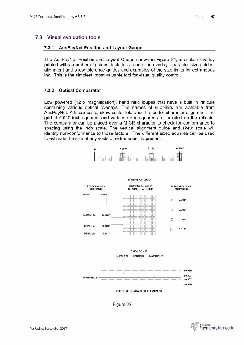
MICR Technical Specifications V 3.3.2 P a g e | 47
AusPayNet September 2017
7.3 Visual evaluation tools
7.3.1 AusPayNet Position and Layout Gauge
The AusPayNet Position and Layout Gauge shown in Figure 21, is a clear overlay printed with a number of guides, includes a code-line overlay, character size guides, alignment and skew tolerance guides and examples of the size limits for extraneous ink. This is the simplest, most valuable tool for visual quality control.
7.3.2 Optical Comparator
Low powered (12 x magnification), hand held loupes that have a built in reticule containing various optical overlays. The names of suppliers are available from AusPayNet. A linear scale, skew scale, tolerance bands for character alignment, the grid of 0.010 inch squares, and various sized squares are included on the reticule. The comparator can be placed over a MICR character to check for conformance to spacing using the inch scale. The vertical alignment guide and skew scale will identify non-conformance to those factors. The different sized squares can be used to estimate the size of any voids or extraneous ink present.
Figure 22
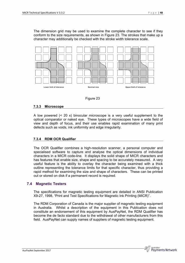
MICR Technical Specifications V 3.3.2 P a g e | 48
AusPayNet September 2017
The dimension grid may be used to examine the complete character to see if they conform to the size requirements, as shown in Figure 23. The strokes that make up a character may additionally be checked with the stroke width tolerance scale.
Figure 23
7.3.3 Microscope
A low powered (< 20 x) binocular microscope is a very useful supplement to the optical comparator or naked eye. These types of microscopes have a wide field of view and depth of focus, and their use enables rapid examination of many print defects such as voids, ink uniformity and edge irregularity.
7.3.4 RDM OCR Qualifier
The OCR Qualifier combines a high-resolution scanner, a personal computer and specialised software to capture and analyse the optical dimensions of individual characters in a MICR code-line. It displays the solid shape of MICR characters and has features that enable size, shape and spacing to be accurately measured. A very useful feature is the ability to overlay the character being examined with a thick outline representing the tolerance limits for that specific character, thus providing a rapid method for examining the size and shape of characters. These can be printed out or stored on disk if a permanent record is required.
7.4 Magnetic Testers
The specifications for magnetic testing equipment are detailed in ANSI Publication X9-27, 1998, “Print and Test Specifications for Magnetic Ink Printing (MICR)”.
The RDM Corporation of Canada is the major supplier of magnetic testing equipment in Australia. Whilst a description of the equipment in this Publication does not constitute an endorsement of this equipment by AusPayNet, the RDM Qualifier has become the de facto standard due to the withdrawal of other manufacturers from this field. AusPayNet can supply names of suppliers of magnetic testing equipment.

MICR Technical Specifications V 3.3.2 P a g e | 49
AusPayNet September 2017
7.4.1 RDM MICR Qualifier
At the time of publication, this system is the only one that fully meets the requirements of ANSI X9-27. It consists of a document transport linked to a PC with a colour monitor. It can be linked to a printer for a permanent visual record of the test result. The instrument uses an analysis of waveforms to determine signal strength, character identification and spacing; this information then being used to check format. When calibrated correctly, this system allows quick, accurate and consistent analysis of MICR. In addition to printing the results, they can be saved to the PC’s hard drive. As the character is measured magnetically and the standards are visual, advisory instructions are often displayed for a supplementary visual check on character shape and size.
7.4.2 Table top MICR testers
Less complex systems are available that do not have to be connected to a PC, and are more portable and rugged. These are thus suitable for use in a production environment, such as proof centers and cheque printers. In most cases, the read head moves past the cheque and the results are displayed on a built in display panel. The results displayed typically include signal strength, character spacing and format and waveforms. The instruments may be able to be connected to a printer and a PC if a permanent record is required.
7.4.3 Lower level testers
Simple, low cost devices are available that are suitable for monitoring low volume cheque printing, such as desk-top laser MICR printers. Typically they transport the cheque past the read-head and gives a simple display of the codeline and signal strength range or for individual characters.
7.4.4 Calibration Documents
Calibration documents are required to periodically check and adjust the signal measurement of the MICR testers. These can be obtained from the suppliers of the test equipment and should be changed regularly as they deteriorate with use. Details of the calibration process are contained in the user documentation of MICR testers. These documents are known as secondary reference standards and their production is carefully monitored by ANSI. The documents are usually printed with a single domestic character in the centre of the codeline and have the measured signal strength individually noted on the document.
Amended, effective 19/05/08
7.5 Quality Assurance Procedures
The establishment of Quality Assurance Procedures is the responsibility of producers of MICR encoded documents and the Financial Institutions to which the documents are presented. The procedures cannot be rigidly prescribed, as they need to be appropriate for the size of the operation, the technology in use and the skill of the personnel in production and use of MICR documents. For example the problems likely to be encountered by letterpress printing of MICR will be very different from those experienced by operators of MICR laser printers.

MICR Technical Specifications V 3.3.2 P a g e | 50
AusPayNet September 2017
The information presented here is a guide to the various methods and tools available to ensure that information printed on MICR documents is correctly positioned and that the MICR print quality standards are being met. These procedures also have to be supplemented by those for design, layout and colour as required by the Design Specifications for Cheques and Deposit Forms.
Amended, effective 19/05/08
7.5.1 Optical Evaluation
The MICR print specifications are based on optical dimensions and positioning thus the initial tests are simple optical tests. These can be carried out with the Position and Layout gauge, supplemented by the Optical Comparator. The document should be inserted in the Position and Layout gauge between the clear plastic overlay and the opaque backing material. It is to be position so that the bottom edge is aligned with the bottom of the pocket and the right-hand reference edge is exactly aligned with the right-hand end of the gauge (noted with an arrow). The document is then in position to examine the codeline.
Figure 24
MICR Clear Band The bottom 5/8 inch of a document should be
checked to see if it is clear of ink other than that for the printed characters and the background design if it intrudes into the area. The background should be
MICR Technical Specifications V 3.3.2 P a g e | 51
AusPayNet September 2017
printed in scan non-readable ink. Any extraneous ink or other printing that is present in scan-readable ink should be less than .004 inch by .004 inch (refer 2.2.6) and can be checked with the optical comparator.
If incorrectly setup, laser printers can produce large
numbers of small magnetic spots which need to be carefully checked for conformance. Laser printed signatures also need care to ensure they do not intrude into the 5/8 inch band, especially where they contain descending characters.
Set-off Wet ink may “set-off” on the reverse of a sheet above
it in a stack. Where this occurs on the reverse of the 5/8th inch MICR clear band, the same restrictions apply as for the front of the sheet.
Position The BSB symbol is used as the reference character
for position and should be in position 29 of the layout gauge’s codeline. If it is not, move the document horizontally until it is in position and check that the codeline falls within the horizontal and vertical tolerance limits as indicated on the gauge, (refer 2.3.5).
Format and contents The information in the codeline is to be checked to
ensure that the data is in the correct fields (refer section 3) and correctly conforms to the issuing Financial Institution’s Confirmatory Authority.
Spacing The spacing of characters in individual fields must not
vary by more than ± 0.010 inch and must not exceed the field limits (refer 2.1.3), additional tolerances apply between fields separated by a blank space.
Alignment The bottom edge of characters must not vary more
than ± 0.030 inch (refer 2.1.4), this can be checked with the Alignment scale on the gauge or more accurately with the optical comparator.
Skew – character/field The gauge and comparator have scales to measure
the skew which must be < 1.50 for characters and in any field of a codeline (refer 2.1.5).
Dimensions The gauge has representations of characters at the
nominal, maximum and minimum sizes. The codeline should be compared with these and if there is any doubt that the characters conform to standard, they should be checked with the pocket comparator and the grids shown in Appendix 2. This is particularly common for Letterpress and Offset printing as the operating conditions may vary to cause out of tolerance conditions.
MICR Technical Specifications V 3.3.2 P a g e | 52
AusPayNet September 2017
A systematic deviation from standards could also be checked with the more accurate RDM OCR Qualifier and corrections made to the font by the typesetter or printer supplier.
Printing Print quality covers voids, edge irregularity,
extraneous ink as well as matters covered above. A preliminary examination of documents with a pocket comparator or loupe can usefully be supplemented by use of a low powered microscope if faults require a more detailed examination.
Offset and Letterpress printing are prone to some
print problems such as voids, edge irregularity and dimensional errors. Ribbon encoding is prone to voids or edge irregularity if the ribbon does not transfer properly. Non-impact printers are also commonly subject to extraneous ink. Voids and edge irregularities can also occur if toner levels are too low.
Debossment This most commonly occurs with Ribbon encoding
and Letterpress printing if the equipment is not properly setup. There are no instruments commonly available to measure debossment. No raised areas on the reverse of a codeline should be visible to the eye or able to be detected by fingertip touch. If either occurred, there would be concern about debossment being within specification.
7.5.2 Magnetic evaluation
The only magnetic characteristic specified is the signal strength of the MICR print. The test equipment described above can however supplement the optical measurements and in many cases replace them. The waveforms and the peaks used for signal strength measurements are shown in Appendix 2 alongside the outlines of the character superimposed on the grid pattern. These are not specified by the standard, as there will be some variation in these waveforms dependant on the method of measurement. The ANSI X9-27 standard however specifies how the measurement is to be carried out for the purposes of signal strength and that method has been adopted by this standard.
The physical measurements provided by MICR test equipment is based upon waveform analysis and deviations should be confirmed by visual methods. Experience with the test equipment and the printing method can provide confidence that the physical measurements taken can be used to check conformance to these standards. Once experience has confirmed the magnetic testing is accurate for the printing technology in use, a number of the visual checks can be replaced by the more automated magnetic tests.
Magnetic testers are however poor at detecting print defects such as voids and edge irregularities hence some form of visual assessment of print quality must still be maintained.
Signal Strength The common standard is the Domestic symbol (refer
2.2.10) and must be between 75% and 200%. Spacing Most instruments provide some detail of the spacing.
MICR Technical Specifications V 3.3.2 P a g e | 53
AusPayNet September 2017
Format Most instruments can check the format against
Australian specifications; errors need to be checked against the Confirmatory Authority before acceptance as incorrect.
Waveform The RDM Qualifier gives very detailed waveforms and
comparison with the nominal waveform. As noted above, the waveform does not form part of the standard but does provide useful information. For example skew distorts the waveform in a predictable manner and extraneous ink can easily be detected.
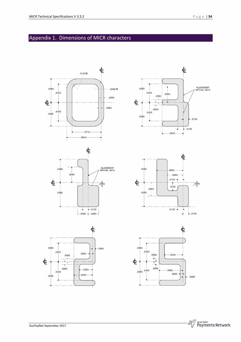
MICR Technical Specifications V 3.3.2 P a g e | 54
AusPayNet September 2017
Appendix 1. Dimensions of MICR characters
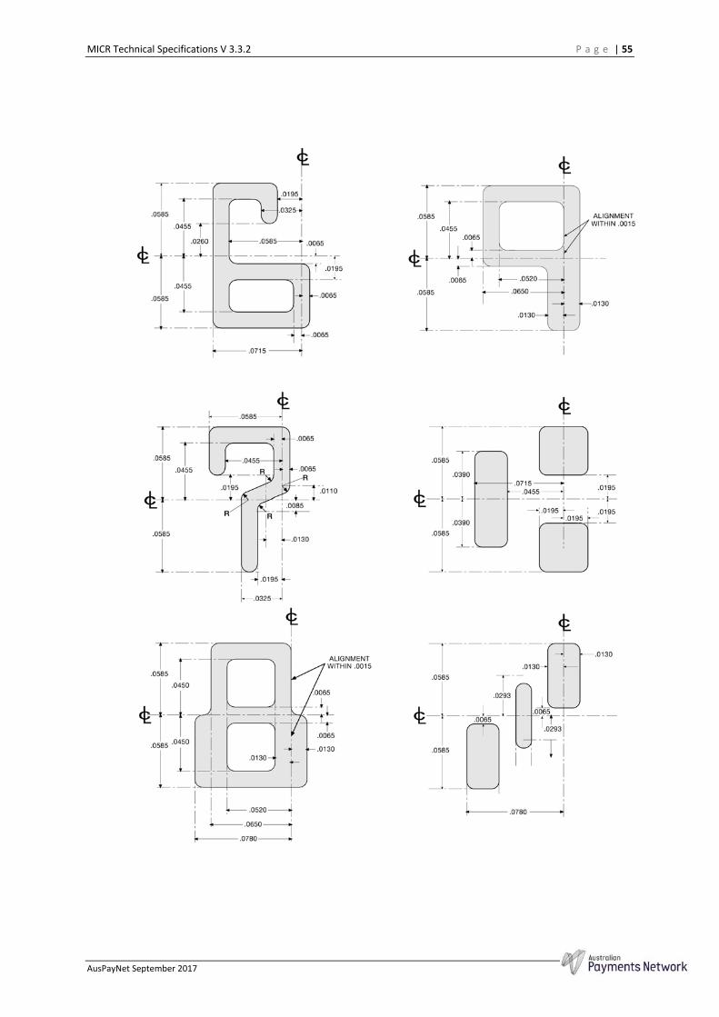
MICR Technical Specifications V 3.3.2 P a g e | 55
AusPayNet September 2017

MICR Technical Specifications V 3.3.2 P a g e | 56
AusPayNet September 2017

MICR Technical Specifications V 3.3.2 P a g e | 57
AusPayNet September 2017
Appendix 2. MICR Character Tolerances and Waveforms
This Appendix shows the ideal shape each of the MICR numbers and symbols outlined against the 0.010 inch grid. The straight edges of each character should ideally run midway down the 0.003 inch space between the squares. The allowed tolerance is the edge of the adjacent square.
Illustrated next to the character outline is the nominal theoretical waveform for that character, with the peak(s) used for measurement of signal strength noted. All relate to the reference peak for the Domestic symbol that is rated at 100. These waveforms are mathematically derived from a theoretical model based on the design of the MICR tester defined in ANSI X9-27 and ideal MICR characters. These characters have perfect edges and dimensions, completely uniform ink cover and the magnetisation is parallel to the plane of the paper.
These waveforms are not specified as standards because commercially available test equipment and printed MICR documents cannot conform exactly to the model. These is however sufficiently good correlation between the model and actual waveforms for them to be a very useful tool in examining the quality of MICR.
The signal strength derived from the reference peaks is definitely defined as a standard and is shown in the table below together with the high and low tolerance levels at 75% to 200% of the nominal. Printed documents must conform to these tolerance limits.
MICR Character
Reference Peak
Minimum Signal
Level (75%)
Nominal Signal Level
Maximum Signal Level
(200%)
0 1 98 130 260
1 1 64 85 170
2 2 79 105 210
3 1 64 85 170
4 1 79 105 210
5 3 79 105 210
6 1 79 105 210
7 5 56 75 150
8 1 79 105 210
9 4 113 165 330
B" 1 & 5 (average)
53 70 140
C 3 & 5 (average)
75 100 200
A 3 79 105 210
> 3 & 5 (average)
50 67 134
Amended, effective 19/05/08
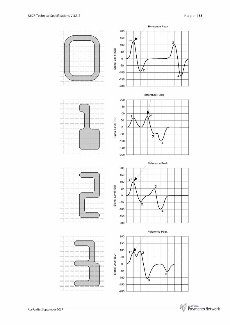
MICR Technical Specifications V 3.3.2 P a g e | 58
AusPayNet September 2017
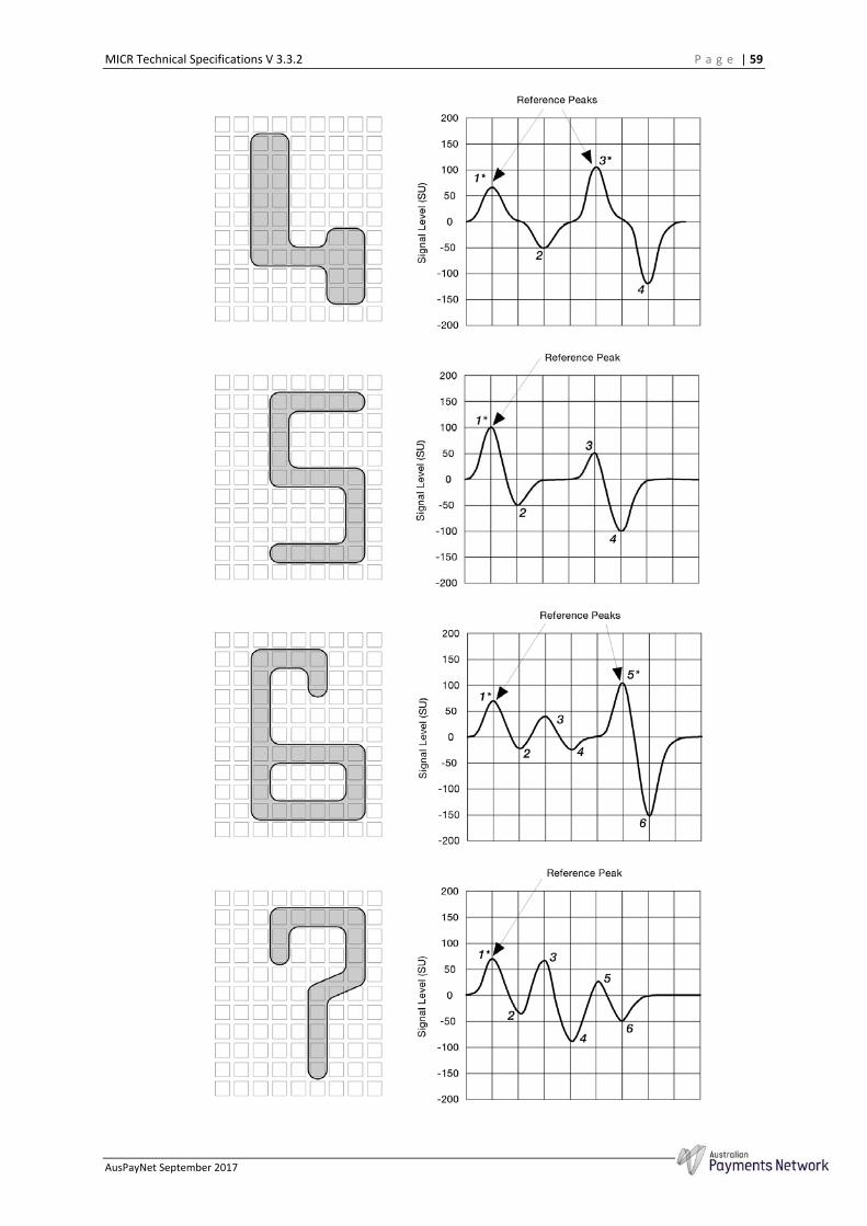
MICR Technical Specifications V 3.3.2 P a g e | 59
AusPayNet September 2017
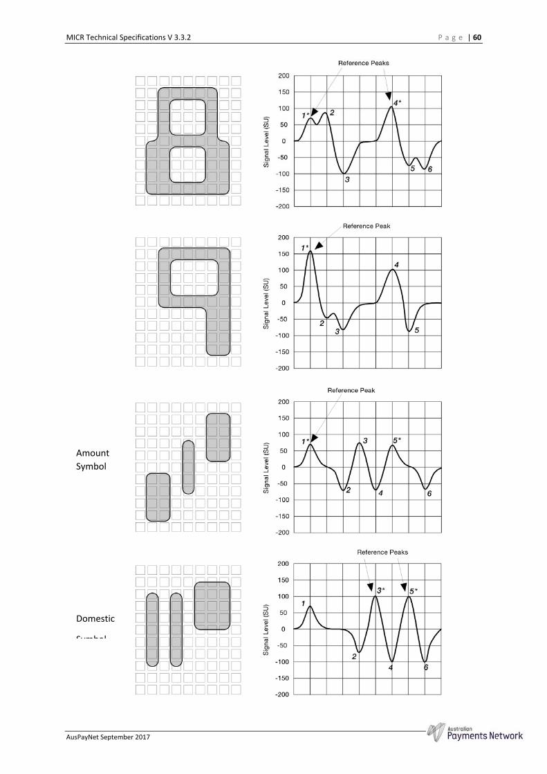
MICR Technical Specifications V 3.3.2 P a g e | 60
AusPayNet September 2017
Domestic
Symbol
Amount
Symbol

MICR Technical Specifications V 3.3.2 P a g e | 61
AusPayNet September 2017
Dash
Symbol

MICR Technical Specifications V 3.3.2 P a g e | 62
AusPayNet September 2017
Appendix 3 MICR Accreditation Procedures
1. Accreditation of MICR Printing Systems Amended, effective 15/09/06
1.1 Definitions "Applicant" means:
(a) In the case of an Original System the manufacturer of that Original System, or their agent and
(b) In the case of a Modified System the person, or entity, who owns that
Modified Printing System.
"Modified System" means a Printing System in which some or all of the components of that Printing System have been modified or customised for the owner of that Printing System, so that it operates in a manner different to that produced by the manufacturer.
"Printing System" means a system of Printing Technology that is claimed to be suitable for printing MICR documents, with components that may include a print engine, magnetic toner, operating system, Page Description Language (PDL) and version of the El3B font. Systems such as those used for proof encoding, and that print MICR, are classed as Printing Systems. "Printing Technology" means the printing process used for printing MICR documents. The major technologies are:
Letterpress Wet Offset Impact or Ribbon transfer Non-Impact
- Laser - Light Emitting Diode (LED) - Magnetographic - Electron Beam (formerly ion deposition)
"Original System" means a Printing System as produced by a manufacturer.
1.2 Objectives Amended, effective 15/09/06
In order to protect the efficiency of the clearing system, it is important to monitor the use of Printing Systems so as to attempt to reduce the amount of poor quality documents entering the system. A testing procedure has been developed which leads to the accreditation and registration of Printing Systems that can reliably produce MICR documents of an acceptable quality. The aim is that the accreditation procedures can be relied upon by APCS Framework Participants as evidence of capacity to provide MICR encoding of an acceptable standard. Accreditation indicates that a Printing System, when operated in accordance with the Applicant's specifications, is capable of producing acceptable MICR encoding and has passed tests for accreditation of MICR Printing Systems as detailed below. However, due to manufacturing and/or operating variances, accreditation is not a guarantee that an individual Printing System will produce acceptable results.
Accreditation is subject to ongoing evaluation, refer to section 1.9 of this Appendix.

MICR Technical Specifications V 3.3.2 P a g e | 63
AusPayNet September 2017
1.3 Summary of the Process Amended, effective 15/09/06
The Applicant begins the accreditation process by providing an application for testing to AusPayNet. The form of application is outlined in section 1.4 of this Appendix and must include the results of bench testing performed on the Printing System and/or evidence of all existing accreditations claimed by the Applicant in respect of the Printing System. AusPayNet will review the application and, if necessary, may request further information from the Applicant. Once an application is accepted, field testing takes place at the data centres of various Tier 1A Participating Members selected by AusPayNet. The results of the field testing are then reviewed by AusPayNet and AusPayNet will decide whether, on the basis of the results, the Printing System is capable of reliably producing MICR documents of an acceptable standard. The Applicant will be informed of AusPayNet’s decision and will have a right of re-test. AusPayNet may, in its absolute discretion, accept existing accreditations with other bodies as meeting part or all of the requirements of the accreditation process. Printing Systems that are capable of producing MICR encoding of an acceptable standard will be accredited and added to AusPayNet's Register of MICR Printing Systems (Register). Accreditation is subject to on-going evaluation.
1.4 Application for Testing Amended, effective 15/09/06
1.4.1 What Printing Systems may be the subject of an Application?
A Printing System is the subject of an application for testing if: (a) It has a speed of 21 or greater A4 pages per minute, or a duty cycle of
75,000 or higher A4 pages/month. and/or
(b) It has potential for high volume production due to the large number of installed units. and/or
(c) The application for re-testing is nominated by an APCS Participating
Member pursuant to section 1.9 of this Appendix.
1.4.2 The Application
Amended, effective 15/09/06
An Applicant must submit an application for testing to AusPayNet prior to commencing field testing. A proforma application is available from AusPayNet upon request.
At a minimum, the application must include details as to the following matters:
(a) The nature of the Printing System to be tested eg. the make and model
number;
(b) The nomination for re-testing of the Printing System by an APCS Participating Member, if relevant, refer to section 1.4.1(c);
(c) The written results of a successful bench test for the Printing System

MICR Technical Specifications V 3.3.2 P a g e | 64
AusPayNet September 2017
and/or a supporting submission by the Applicant if a successful bench test is not possible, refer to section 1.4.3.
(d) Evidence of all existing accreditations with other bodies claimed by the Applicant in respect of the Printing System, refer to section 1.8.
The Applicant must pay an application fee of $2,500 (subject to indexation in accordance with section 2.0 of this Appendix) to AusPayNet. This fee is intended to assist Tier 1A Participating Members nominated to conduct field testing to recoup their costs for out of pocket expenses incurred in conducting those tests. Such fee will be applied by AusPayNet towards the payment of costs and expenses of AusPayNet which would otherwise be borne by Tier 1A Participating Members pursuant to APCS Regulation 6.11.
Where the application for testing is nominated by an APCS Participating Member, refer to section 1.9 of this Appendix.
1.4.3 What is bench testing?
Bench testing is used to evaluate whether the Printing System conforms to its written specifications. An Applicant must have performed bench testing on the relevant Printing System prior to lodging their application with AusPayNet and the application for testing must include a report of the results of the bench testing and/or a supporting submission by the Applicant if a successful bench test is not possible.
Test equipment used for bench testing must conform to ANSI X9.27-1995 part 3, section 6. The test methods outlined in section 6 of this ANSI Publication should be used as a basis for the bench testing and cover the following properties:
Dimensional/Optical measurement:
- Character spacing/Alignment/Skew/Dimensions - Edge irregularity/Voids/Extraneous ink
Magnetic measurement:
- Signal level - Uniformity of ink - Waveforms
Embossment/Debossment
1.4.4 AusPayNet's review of the Application
Amended, effective 22/03/06
Upon receipt of the application, AusPayNet will review the application in preparation for the commencement of field testing and, if necessary, may request further information from the Applicant. AusPayNet may also impose conditions on the field testing if necessary to ensure that the overall objectives outlined above in section 1.2 are met.
Once the application is accepted, AusPayNet will advise the Applicant:
that field testing will commence; and of the Tier 1A Participating Members which will conduct the field testing.
As a guide, AusPayNet will use reasonable endeavours to provide a response to the Applicant within a period of five weeks from the date the application is accepted by AusPayNet.

MICR Technical Specifications V 3.3.2 P a g e | 65
AusPayNet September 2017
1.5 Field Testing Amended, effective 22/03/06
The field testing procedure is designed to examine the quality of the output of a Printing System when set up according to the Applicant's instructions and using paper that conforms to AS 2277. In particular, the aim of field testing is to check that the documents produced by the Printing System are sufficiently robust to perform satisfactorily on the reading equipment used by Tier 1A Participating Members. The assessment of the robustness of the document comprises of a series of test runs through the testing Members’ MICR reading equipment. The tests should cover the full range of machines used by Tier 1A Participating Members taking into account technology, age and speed.
The Printing System must be tested on at least one high speed machine and one medium/low speed machine.
AusPayNet maintains a list of Tier 1A Participating Members available to conduct field testing. AusPayNet, in its absolute discretion, will determine which Tier 1A Participating Members will conduct field testing in respect to any application.
AusPayNet, in its absolute discretion, will also determine if a minimum of two or a maximum of three independent field tests will be conducted in respect to any application.
Where two independent field tests are conducted, the Printing System must pass both field tests. Where three independent field tests are conducted, the Printing System must pass a minimum of two independent field tests.
Testing Tier 1A Participating Members must use reasonable endeavours to complete field testing within a period of four weeks from receipt of the application by the Tier 1A Participating Members.
1.5.1 The Operation of Field testing
1.5.1.1 What Codeline should be used in the field test?
The MICR code line used in the field testing must: be agreed between the Applicant and the relevant Tier 1A Participating
Member conducting the test; and be in the Australian format and include BSB, account number and serial
number fields, the serial number being sequential to uniquely identify each document; and
include at least one of each E-13B character (with the exception of the amount symbol).
If the Printing System being examined is capable of printing in both landscape and portrait orientation and both are to be used, then both must be tested.
Samples of MICR code lines containing single numeric characters must also be run, each of the ten numerals being included, to test for possible substitutions. The printed numerals shall cover the maximum range that the testing Tier 1A Participating Members’ equipment will read and are to be in a format agreed between the testing Members and the Applicant.
1.5.1.2 Test Samples
The Applicant should provide test samples printed on an approved grade of cheque paper and a size that meets current specifications, 8 1/4 inch x 3 2/3 inch (2l0mm x 93mm) is
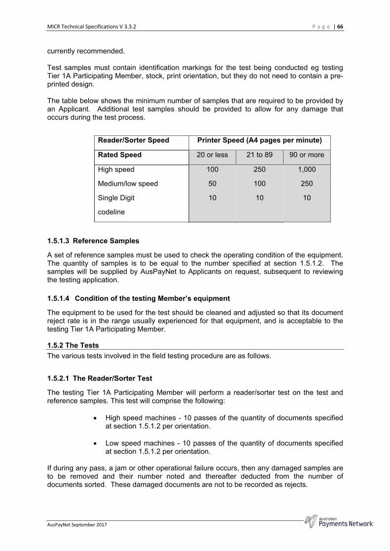
MICR Technical Specifications V 3.3.2 P a g e | 66
AusPayNet September 2017
currently recommended.
Test samples must contain identification markings for the test being conducted eg testing Tier 1A Participating Member, stock, print orientation, but they do not need to contain a pre-printed design.
The table below shows the minimum number of samples that are required to be provided by an Applicant. Additional test samples should be provided to allow for any damage that occurs during the test process.
Reader/Sorter Speed Printer Speed (A4 pages per minute)
Rated Speed 20 or less 21 to 89 90 or more
High speed 100 250 1,000
Medium/low speed 50 100 250
Single Digit 10 10 10
codeline
1.5.1.3 Reference Samples
A set of reference samples must be used to check the operating condition of the equipment. The quantity of samples is to be equal to the number specified at section 1.5.1.2. The samples will be supplied by AusPayNet to Applicants on request, subsequent to reviewing the testing application.
1.5.1.4 Condition of the testing Member’s equipment
The equipment to be used for the test should be cleaned and adjusted so that its document reject rate is in the range usually experienced for that equipment, and is acceptable to the testing Tier 1A Participating Member.
1.5.2 The Tests
The various tests involved in the field testing procedure are as follows.
1.5.2.1 The Reader/Sorter Test
The testing Tier 1A Participating Member will perform a reader/sorter test on the test and reference samples. This test will comprise the following:
High speed machines - 10 passes of the quantity of documents specified
at section 1.5.1.2 per orientation.
Low speed machines - 10 passes of the quantity of documents specified at section 1.5.1.2 per orientation.
If during any pass, a jam or other operational failure occurs, then any damaged samples are to be removed and their number noted and thereafter deducted from the number of documents sorted. These damaged documents are not to be recorded as rejects.
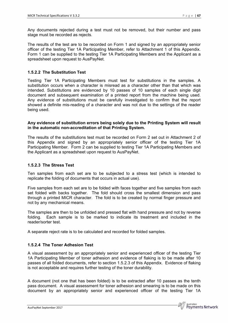
MICR Technical Specifications V 3.3.2 P a g e | 67
AusPayNet September 2017
Any documents rejected during a test must not be removed, but their number and pass stage must be recorded as rejects.
The results of the test are to be recorded on Form 1 and signed by an appropriately senior officer of the testing Tier 1A Participating Member, refer to Attachment 1 of this Appendix. Form 1 can be supplied to the testing Tier 1A Participating Members and the Applicant as a spreadsheet upon request to AusPayNet.
1.5.2.2 The Substitution Test
Testing Tier 1A Participating Members must test for substitutions in the samples. A substitution occurs when a character is misread as a character other than that which was intended. Substitutions are evidenced by 10 passes of 10 samples of each single digit document and subsequent examination of a printed report from the machine being used. Any evidence of substitutions must be carefully investigated to confirm that the report showed a definite mis-reading of a character and was not due to the settings of the reader being used.
Any evidence of substitution errors being solely due to the Printing System will result in the automatic non-accreditation of that Printing System.
The results of the substitutions test must be recorded on Form 2 set out in Attachment 2 of this Appendix and signed by an appropriately senior officer of the testing Tier 1A Participating Member. Form 2 can be supplied to testing Tier 1A Participating Members and the Applicant as a spreadsheet upon request to AusPayNet.
1.5.2.3 The Stress Test
Ten samples from each set are to be subjected to a stress test (which is intended to replicate the folding of documents that occurs in actual use). Five samples from each set are to be folded with faces together and five samples from each set folded with backs together. The fold should cross the smallest dimension and pass through a printed MICR character. The fold is to be created by normal finger pressure and not by any mechanical means. The samples are then to be unfolded and pressed flat with hand pressure and not by reverse folding. Each sample is to be marked to indicate its treatment and included in the reader/sorter test. A separate reject rate is to be calculated and recorded for folded samples.
1.5.2.4 The Toner Adhesion Test
A visual assessment by an appropriately senior and experienced officer of the testing Tier 1A Participating Member of toner adhesion and evidence of flaking is to be made after 10 passes of all folded documents, refer to section 1.5.2.3 of this Appendix. Evidence of flaking is not acceptable and requires further testing of the toner durability.
A document (not one that has been folded) is to be extracted after 10 passes as the tenth pass document. A visual assessment for toner adhesion and smearing is to be made on this document by an appropriately senior and experienced officer of the testing Tier 1A
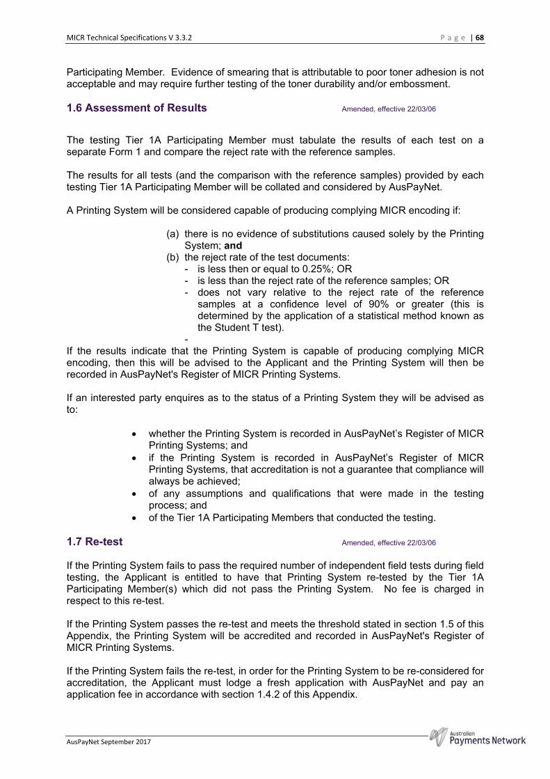
MICR Technical Specifications V 3.3.2 P a g e | 68
AusPayNet September 2017
Participating Member. Evidence of smearing that is attributable to poor toner adhesion is not acceptable and may require further testing of the toner durability and/or embossment.
1.6 Assessment of Results Amended, effective 22/03/06
The testing Tier 1A Participating Member must tabulate the results of each test on a separate Form 1 and compare the reject rate with the reference samples.
The results for all tests (and the comparison with the reference samples) provided by each testing Tier 1A Participating Member will be collated and considered by AusPayNet.
A Printing System will be considered capable of producing complying MICR encoding if:
(a) there is no evidence of substitutions caused solely by the Printing
System; and (b) the reject rate of the test documents:
- is less then or equal to 0.25%; OR - is less than the reject rate of the reference samples; OR - does not vary relative to the reject rate of the reference
samples at a confidence level of 90% or greater (this is determined by the application of a statistical method known as the Student T test).
- If the results indicate that the Printing System is capable of producing complying MICR encoding, then this will be advised to the Applicant and the Printing System will then be recorded in AusPayNet's Register of MICR Printing Systems.
If an interested party enquires as to the status of a Printing System they will be advised as to:
whether the Printing System is recorded in AusPayNet’s Register of MICR
Printing Systems; and if the Printing System is recorded in AusPayNet’s Register of MICR
Printing Systems, that accreditation is not a guarantee that compliance will always be achieved;
of any assumptions and qualifications that were made in the testing process; and
of the Tier 1A Participating Members that conducted the testing. 1.7 Re-test Amended, effective 22/03/06
If the Printing System fails to pass the required number of independent field tests during field testing, the Applicant is entitled to have that Printing System re-tested by the Tier 1A Participating Member(s) which did not pass the Printing System. No fee is charged in respect to this re-test.
If the Printing System passes the re-test and meets the threshold stated in section 1.5 of this Appendix, the Printing System will be accredited and recorded in AusPayNet's Register of MICR Printing Systems.
If the Printing System fails the re-test, in order for the Printing System to be re-considered for accreditation, the Applicant must lodge a fresh application with AusPayNet and pay an application fee in accordance with section 1.4.2 of this Appendix.

MICR Technical Specifications V 3.3.2 P a g e | 69
AusPayNet September 2017
1.8 Other Accreditations Inserted, effective 15/09/06
AusPayNet may, in its absolute discretion, accept existing accreditations with other bodies as meeting part or all of the requirements of the accreditation process outlined above.
1.9 On-Going Evaluation Amended, effective 15/09/06
If an APCS Participating Member is of the view that an accredited Printing System is resulting in an unacceptable level of rejects, such that it is no longer clear that the Printing System is capable of producing MICR encoding of an acceptable standard, then that Member may nominate the Printing System for retesting in accordance with section 1.4.1 of this Appendix.
AusPayNet will advise the Applicant of the request for a retest. The Applicant may then decide to:
seek to have its Printing System withdrawn from the Register (without a
retest); submit to the retest; or make a submission to AusPayNet to oppose the request for a retest.
If the Applicant submits to the retest the Applicant must pay a fee of $2,500 (subject to indexation in accordance with section 2.0 of this Appendix) to AusPayNet. This fee is intended to assist Tier 1A Participating Members nominated to conduct re-testing to recoup their costs for out of pocket expenses incurred in conducting those tests. Such fee will be applied by AusPayNet towards the payment of costs and expenses of AusPayNet which would otherwise be borne by Tier 1A Participating Members pursuant to APCS Regulation 6.11.
The Printing System will be temporarily withdrawn from the Register for the duration of the testing process. The reason for the temporary withdrawal (ie re-testing in process) will be noted in the Register and advised to any interested party who makes an enquiry in relation to that Printing System.
If the Printing System passes the retest, the Printing System will be reinstated on the Register and the fee charged for conducting the re-test will be refunded to the Applicant.
If the Printing System does not pass the retest, the Printing System will be permanently withdrawn from the Register. The Applicant must advise owners of installed systems of the withdrawal of the Printing System from the Register.
If the Applicant makes a submission to oppose the request for a retest, the APCS Participating Member that made the request, and any other interested party, may make submissions to AusPayNet in respect of the request. After consideration of the submissions put to it, with any interested APCS Framework Participants not to participate in the decision making process, AusPayNet will make a decision as to whether:
it is reasonably unclear as to whether the Printing System is capable of
producing acceptable MICR encoding, in which case the Printing System should either be withdrawn from the register or re-tested in accordance with sections 1.4 and 1.5 of this Appendix. If the Applicant does not consent to the re-testing, the Printing System will be withdrawn from the Register; or
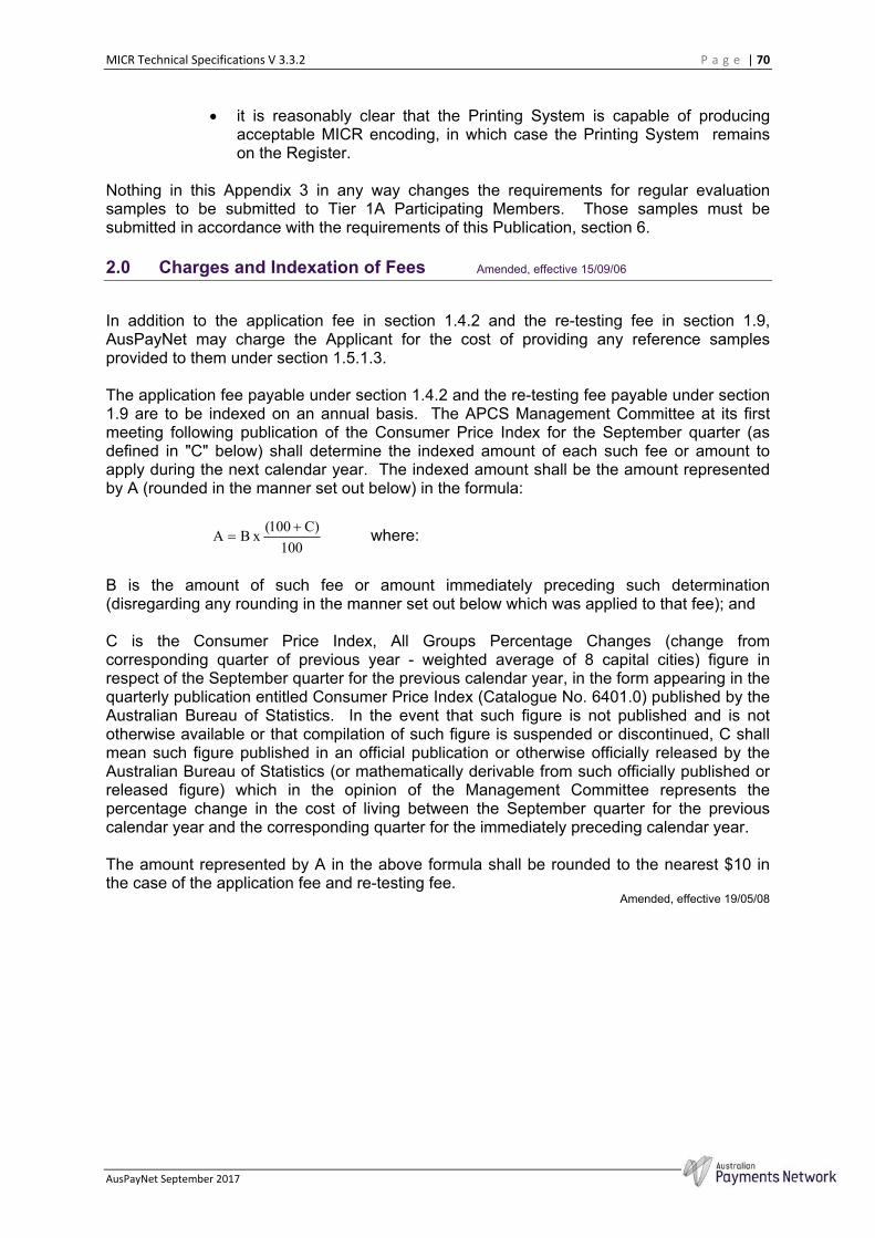
MICR Technical Specifications V 3.3.2 P a g e | 70
AusPayNet September 2017
it is reasonably clear that the Printing System is capable of producing acceptable MICR encoding, in which case the Printing System remains on the Register.
Nothing in this Appendix 3 in any way changes the requirements for regular evaluation samples to be submitted to Tier 1A Participating Members. Those samples must be submitted in accordance with the requirements of this Publication, section 6. 2.0 Charges and Indexation of Fees Amended, effective 15/09/06
In addition to the application fee in section 1.4.2 and the re-testing fee in section 1.9, AusPayNet may charge the Applicant for the cost of providing any reference samples provided to them under section 1.5.1.3.
The application fee payable under section 1.4.2 and the re-testing fee payable under section 1.9 are to be indexed on an annual basis. The APCS Management Committee at its first meeting following publication of the Consumer Price Index for the September quarter (as defined in "C" below) shall determine the indexed amount of each such fee or amount to apply during the next calendar year. The indexed amount shall be the amount represented by A (rounded in the manner set out below) in the formula:
100
)C100( x BA
where:
B is the amount of such fee or amount immediately preceding such determination (disregarding any rounding in the manner set out below which was applied to that fee); and
C is the Consumer Price Index, All Groups Percentage Changes (change from corresponding quarter of previous year - weighted average of 8 capital cities) figure in respect of the September quarter for the previous calendar year, in the form appearing in the quarterly publication entitled Consumer Price Index (Catalogue No. 6401.0) published by the Australian Bureau of Statistics. In the event that such figure is not published and is not otherwise available or that compilation of such figure is suspended or discontinued, C shall mean such figure published in an official publication or otherwise officially released by the Australian Bureau of Statistics (or mathematically derivable from such officially published or released figure) which in the opinion of the Management Committee represents the percentage change in the cost of living between the September quarter for the previous calendar year and the corresponding quarter for the immediately preceding calendar year.
The amount represented by A in the above formula shall be rounded to the nearest $10 in the case of the application fee and re-testing fee.
Amended, effective 19/05/08

MICR Technical Specifications V 3.3.2 P a g e | 71
AusPayNet September 2017
Attachment 1
Form 1 - Test report for assessment of MICR print quality
Initiating organisation(s):
Date :
Testing organisation:
Make/model of printer:
Method of printing:
Font identification:
Font alignment:
Make/model of reader/sorter:
Source of test vouchers:
Control vouchers:
Encoding:
Number Range:
Comments:
Identify manufacturer or vendor and other interested parties
Date of testing
Tier 1A Participating Member
Manufacturer’s name and model name/number
Technology in use
Suppliers identification of E-13B version
Portrait/Landscape
Bank equipment
Printing company, technology
Y/N
Code line
Serial numbers
Details of assessment, any abnormalities experienced
Test results Pass Input
items Reject items
Jams Damaged documents
Folded documents
Folded rejects
1
2
3
4
5
6
7
8
9
10
Totals
Reject rate
Notes:
1 All rejects and jammed documents that are not damaged are to be return to the sample deck being tested. Note damaged documents removed in appropriate column. (refer section 1.5.2.1 )
2 Number of input items should be as detailed in section 1.5.1.2 3 Sample size for folded documents is a minimum of 10 to be marked and included with items in 2 above. Calculate a
separate reject rate. 4 Attach to this sheet a sample document after 10 passes. This is to be assessed for toner adhesion.
Confirmation of results by testing Tier 1A Participating Member
The tests were conducted according to the designated methods
FI ………………………………….
ACN/ABN/ARBN ………………………………….
Name ………………………………….
Signature ………………………………….
Date …../…../…..
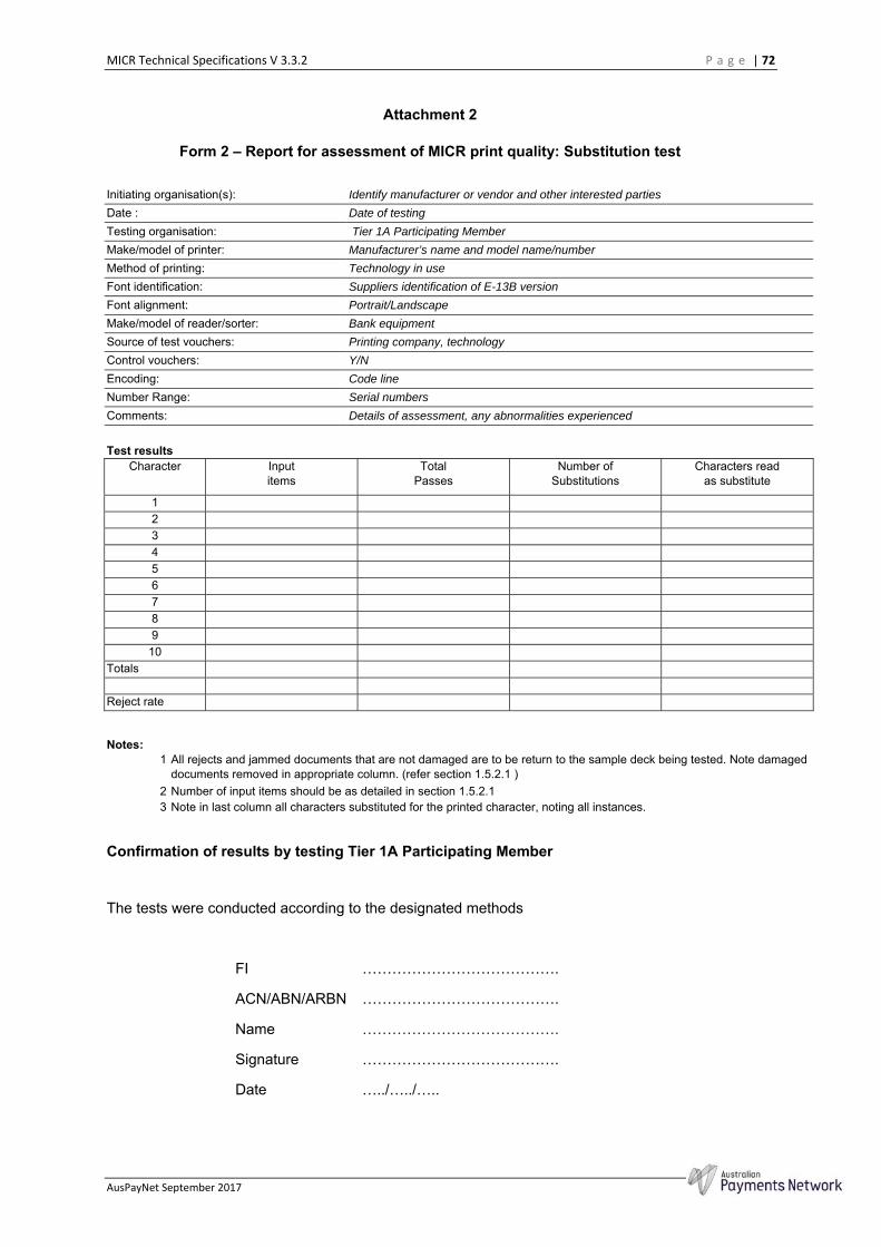
MICR Technical Specifications V 3.3.2 P a g e | 72
AusPayNet September 2017
Attachment 2
Form 2 – Report for assessment of MICR print quality: Substitution test
Initiating organisation(s):
Date :
Testing organisation:
Make/model of printer:
Method of printing:
Font identification:
Font alignment:
Make/model of reader/sorter:
Source of test vouchers:
Control vouchers:
Encoding:
Number Range:
Comments:
Identify manufacturer or vendor and other interested parties
Date of testing
Tier 1A Participating Member
Manufacturer’s name and model name/number
Technology in use
Suppliers identification of E-13B version
Portrait/Landscape
Bank equipment
Printing company, technology
Y/N
Code line
Serial numbers
Details of assessment, any abnormalities experienced
Test results
Character Input items
Total Passes
Number of Substitutions
Characters read as substitute
1
2
3
4
5
6
7
8
9
10
Totals
Reject rate
Notes: 1 All rejects and jammed documents that are not damaged are to be return to the sample deck being tested. Note damaged
documents removed in appropriate column. (refer section 1.5.2.1 ) 2 Number of input items should be as detailed in section 1.5.2.1 3 Note in last column all characters substituted for the printed character, noting all instances.
Confirmation of results by testing Tier 1A Participating Member
The tests were conducted according to the designated methods
FI ………………………………….
ACN/ABN/ARBN ………………………………….
Name ………………………………….
Signature ………………………………….
Date …../…../…..