MAGNETIC FLUX LEAKAGE - A COMPARATIVE ASSESSMENT OF … · the magnetic flux leakage technique is...
17
MENDT- 7 PAGE 1 SEPTEMBER 29, 2015 MENDT 7- BAHRAIN 09-2015 MAGNETIC FLUX LEAKAGE - A COMPARATIVE ASSESSMENT OF THE ADVANTAGES AND DISADVANTAGES OF THIS TUBE INSPECTION TECHNIQUE
Transcript of MAGNETIC FLUX LEAKAGE - A COMPARATIVE ASSESSMENT OF … · the magnetic flux leakage technique is...

MENDT- 7 PAGE 1 SEPTEMBER 29, 2015
MENDT 7- BAHRAIN
09-2015
MAGNETIC FLUX LEAKAGE - A COMPARATIVE
ASSESSMENT OF THE ADVANTAGES AND
DISADVANTAGES OF THIS TUBE INSPECTION
TECHNIQUE
INTRODUCTION
•
SEPTEMBER 29, 2015MENDT- 7 PAGE 2
• CONTEXT
• MAGNETIC FLUX LEAKAGE PROBE DESIGN
• Overview
• Principle of Operating
• EQUIPMENT PARAMETERS
• Evaluation Equipment
• Calibration
• MFL Panel layout
• RESULTS COMPARISON
• Volumetric- Grooving & FBH
• Fin Fan- Internal Grooving Resolution
• External Resolution- Pitting Detectability
• Elongated Grooving
• RESULTS TABLE
• EQUIPMENT COMPARISON
• CONCLUSIONS
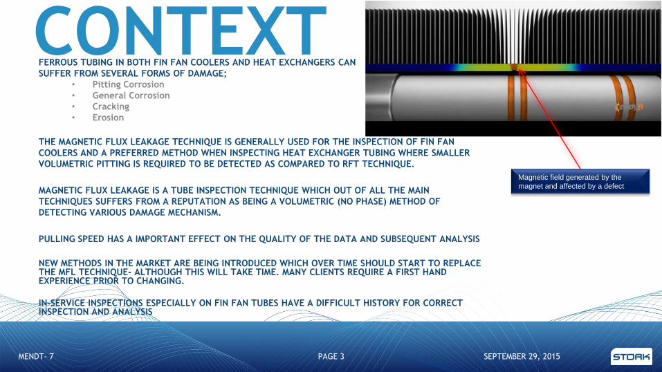
CONTEXTFERROUS TUBING IN BOTH FIN FAN COOLERS AND HEAT EXCHANGERS CAN
SUFFER FROM SEVERAL FORMS OF DAMAGE;
• Pitting Corrosion
• General Corrosion
• Cracking
• Erosion
THE MAGNETIC FLUX LEAKAGE TECHNIQUE IS GENERALLY USED FOR THE INSPECTION OF FIN FAN
COOLERS AND A PREFERRED METHOD WHEN INSPECTING HEAT EXCHANGER TUBING WHERE SMALLER
VOLUMETRIC PITTING IS REQUIRED TO BE DETECTED AS COMPARED TO RFT TECHNIQUE.
MAGNETIC FLUX LEAKAGE IS A TUBE INSPECTION TECHNIQUE WHICH OUT OF ALL THE MAIN
TECHNIQUES SUFFERS FROM A REPUTATION AS BEING A VOLUMETRIC (NO PHASE) METHOD OF
DETECTING VARIOUS DAMAGE MECHANISM.
PULLING SPEED HAS A IMPORTANT EFFECT ON THE QUALITY OF THE DATA AND SUBSEQUENT ANALYSIS
NEW METHODS IN THE MARKET ARE BEING INTRODUCED WHICH OVER TIME SHOULD START TO REPLACE THE MFL TECHNIQUE- ALTHOUGH THIS WILL TAKE TIME. MANY CLIENTS REQUIRE A FIRST HAND EXPERIENCE PRIOR TO CHANGING.
IN-SERVICE INSPECTIONS ESPECIALLY ON FIN FAN TUBES HAVE A DIFFICULT HISTORY FOR CORRECT INSPECTION AND ANALYSIS
SEPTEMBER 29, 2015MENDT- 7 PAGE 3
Magnetic field generated by the
magnet and affected by a defect
MFL THEORY
SEPTEMBER 29, 2015MENDT- 7 PAGE 4
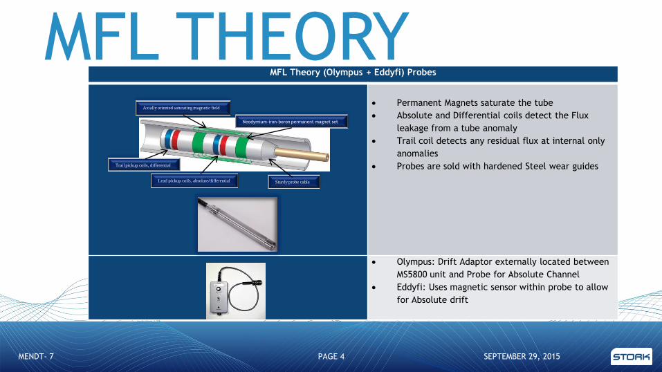
MFL Theory (Olympus + Eddyfi) Probes
Permanent Magnets saturate the tube
Absolute and Differential coils detect the Flux
leakage from a tube anomaly
Trail coil detects any residual flux at internal only
anomalies
Probes are sold with hardened Steel wear guides
Olympus: Drift Adaptor externally located between
MS5800 unit and Probe for Absolute Channel
Eddyfi: Uses magnetic sensor within probe to allow
for Absolute drift
Lead pickup coils, absolute/differential Sturdy probe cable
Trail pickup coils, differential
Axially oriented saturating magnetic field
Neodymium-iron-boron permanent magnet set

DINSEARCH THEORY
SEPTEMBER 29, 2015MENDT- 7 PAGE 5
Electromagnetic Theory (Dinsearch)-
Probes Electromagnetic principle using 110 or
220V mains power
Tube wall is magnetized
Sensors detect the changes in the level of
magnetization (flux) within the tube wall
Probes are continuously air Cooled during
operation
Probes have interchangeable Sheaths to
cater for variations of tube internal
diameters.
Probes can be automated in both the
push and pull directions

EVALUATION EQUIPMENT
Carbon steel tubing both
25mm and 19mm diameters were
used (most common sizes
used in the industry)
Both circumferential and longitudinal
flaws were machined
Externally Pits (flat bottom holes) were machined
Series of machined flaws with equivalent
volume, different depths vs width
for signal comparison
Machined flaws at decreasing
distances apart were machined for resolution
evaluation
Actual fin fan sample was internally machined
SEPTEMBER 29, 2015MENDT-7 PAGE 6

CALIBRATION
SEPTEMBER 29, 2015ASSET LIFECYCLE INTEGRITY PARTNER PAGE 7
Depth Curves Calibration Points Comments
OD Grooves out by
~5 to ~10% of actual
calibration point
machining
Hole at 1.00V
Flat bottom holes
out by between ~5
to ~10% of actual
calibration point
machining
Absolute Channel
Differential Channel

PANEL LAYOUT
SEPTEMBER 29, 2015ASSET LIFECYCLE INTEGRITY PARTNER PAGE 8
EDDYFI MS5800
Absolute AbsoluteDifferential DifferentialTrail Trail
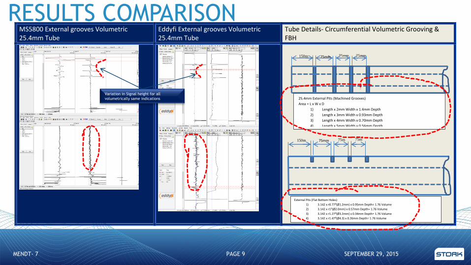
MS5800 External grooves Volumetric 25.4mm Tube
Eddyfi External grooves Volumetric 25.4mm Tube
Tube Details- Circumferential Volumetric Grooving & FBH
75mm 75m
m 75m
m
External Pits (Flat Bottom Holes)
1) 3.142 x r0.77²(Ø1.2mm) x 0.95mm Depth= 1.76 Volume
2) 3.142 x r1²(Ø2.0mm) x 0.57mm Depth= 1.76 Volume
3) 3.142 x r1.27²(Ø3.2mm) x 0.34mm Depth= 1.76 Volume
4) 3.142 x r1.47²(Ø4.3) x 0.26mm Depth= 1.76 Volume
150m
m
75mm 75mm 75mm 150m
m
25.4mm External Pits (Machined Grooves)
Area = L x W x D
1) Length x 2mm Width x 1.4mm Depth
2) Length x 3mm Width x 0.93mm Depth
3) Length x 4mm Width x 0.70mm Depth
4) Length x 5mm Width x 0.56mm Depth
SEPTEMBER 29, 2015MENDT- 7 PAGE 9
Variation in Signal height for all
volumetrically same indications
RESULTS COMPARISON
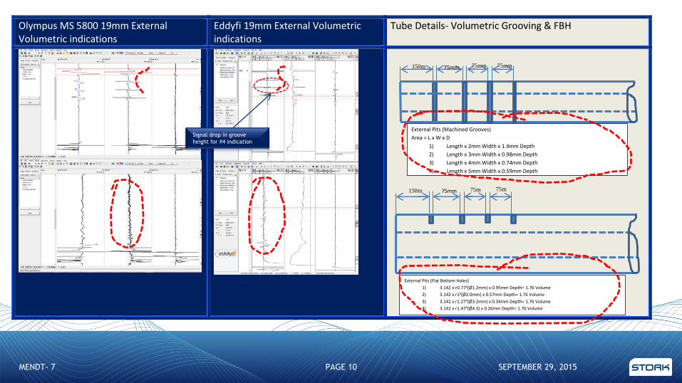
Olympus MS 5800 19mm External Volumetric indications
Eddyfi 19mm External Volumetric indications
Tube Details- Volumetric Grooving & FBH
75mm 75m
m 75m
m
External Pits (Flat Bottom Holes)
1) 3.142 x r0.77²(Ø1.2mm) x 0.95mm Depth= 1.76 Volume
2) 3.142 x r1²(Ø2.0mm) x 0.57mm Depth= 1.76 Volume
3) 3.142 x r1.27²(Ø3.2mm) x 0.34mm Depth= 1.76 Volume
4) 3.142 x r1.47²(Ø4.3) x 0.26mm Depth= 1.76 Volume
150m
m
75mm 75mm 75mm
External Pits (Machined Grooves)
Area = L x W x D
1) Length x 2mm Width x 1.4mm Depth
2) Length x 3mm Width x 0.98mm Depth
3) Length x 4mm Width x 0.74mm Depth
4) Length x 5mm Width x 0.59mm Depth
150m
m
SEPTEMBER 29, 2015MENDT- 7 PAGE 10
Signal drop in groove
height for #4 indication

Olympus Fin Fan Internal Grooving Eddyfi Fin Fan Internal Grooving Tube Details ID Grooving (Resolution)
30
m
25
mm 20
mm 15
mm 10
mm
Notes:
Flat bottom Hole depth to be 50% of Nominal wall thickness
ID grooves to be machined to the internal bore
Groove Width 3mm wide
Internal Grooves-
Fin Fan Sample 5mm
60
mm
SEPTEMBER 29, 2015MENDT- 7 PAGE 11
Signal morphology difference between MS5800
and Eddyfi machines
Signal resolution limited below 15mm indication
separation

MS5800 External Pits Machined 25.4mm & 19.05mm Resolution
Eddyfi External Pits Machined 25.4mm & 19.05mm Resolution
External Pits Resolution & Detectability
50m
m
25m
15m
10m
m 5mm
Notes:
Flat bottom hole depth 50% of Nominal wall thickness
Hole Diameter to be 5mm for 1” Tube and 3mm Diameter for 19mm Tube.
100
mm
SEPTEMBER 29, 2015MENDT- 7 PAGE 12
External Pitting partially defined for both
Systems, indicating minimum external
detectability has been defined
Below 25mm pits are not clearly defined

MS5800 External Flat Bottom Holes Volumetric + Rectangular Slots 19mm
Eddyfi External Flat Bottom Holes Volumetric + Rectangular Slots 19mm
External Elongated Grooving (Elongated Corrosion)
75mm 75mm 75mm
Area = L x W x D
1) 10mm Length x 3mm Width x 1.5mm Depth= 45mm Volume
2) 12mm Length x 3mm Width x 1.25 Depth = 45mm Volume
3) 15mm Length x 3mm Width x 1.0mm Depth = 45mm Volume
4) 20mm Length x 3mm Width x 0.75mm Depth = 45mm Volume
100m
m
SEPTEMBER 29, 2015MENDT- 7 PAGE 13
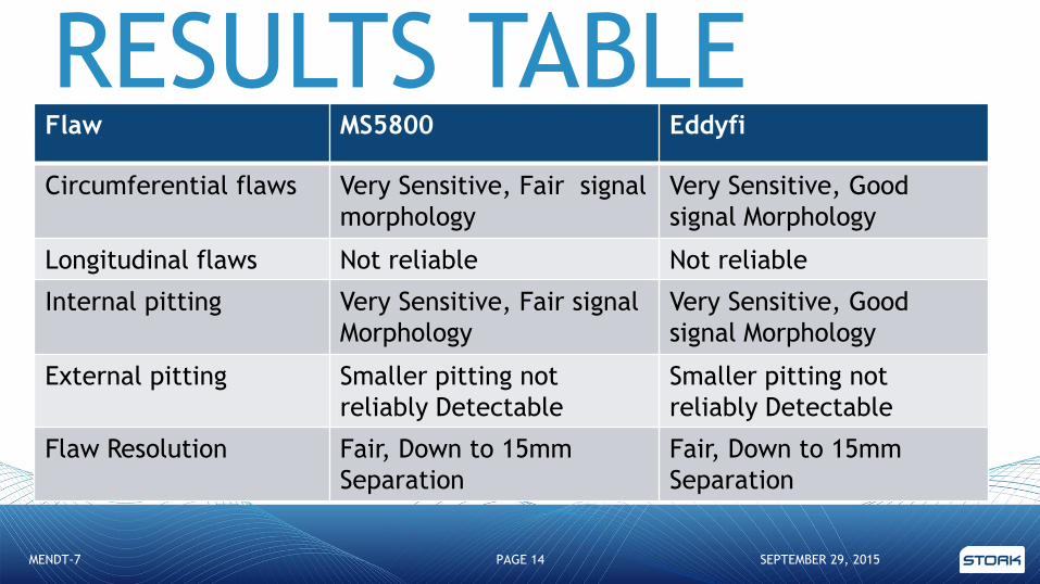
RESULTS TABLE
SEPTEMBER 29, 2015MENDT-7 PAGE 14
Flaw MS5800 Eddyfi
Circumferential flaws Very Sensitive, Fair signal
morphology
Very Sensitive, Good
signal Morphology
Longitudinal flaws Not reliable Not reliable
Internal pitting Very Sensitive, Fair signal
Morphology
Very Sensitive, Good
signal Morphology
External pitting Smaller pitting not
reliably Detectable
Smaller pitting not
reliably Detectable
Flaw Resolution Fair, Down to 15mm
Separation
Fair, Down to 15mm
Separation
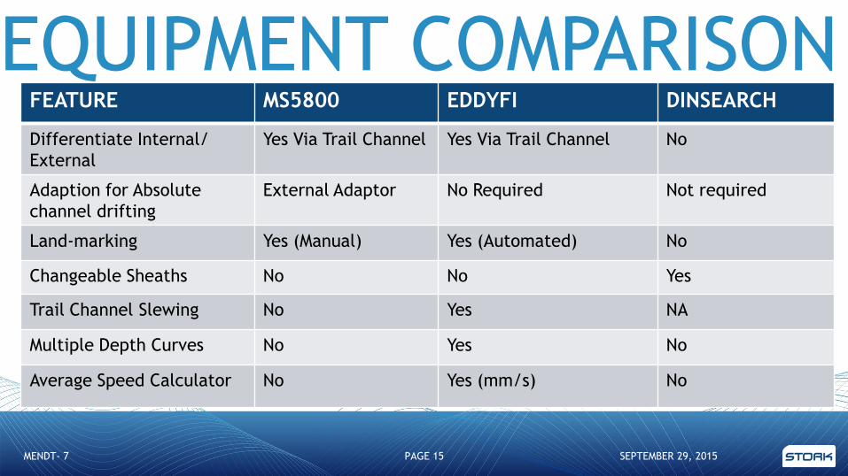
EQUIPMENT COMPARISON
SEPTEMBER 29, 2015MENDT- 7 PAGE 15
FEATURE MS5800 EDDYFI DINSEARCH
Differentiate Internal/
External
Yes Via Trail Channel Yes Via Trail Channel No
Adaption for Absolute
channel drifting
External Adaptor No Required Not required
Land-marking Yes (Manual) Yes (Automated) No
Changeable Sheaths No No Yes
Trail Channel Slewing No Yes NA
Multiple Depth Curves No Yes No
Average Speed Calculator No Yes (mm/s) No

CONCLUSIONSEDDYFI AND OLYMPUS RESULTS ARE COMPARABLE FOR DETECTABILITY OF
BOTH INTERNAL AND EXTERNAL FLAWS
EQUIVALENT FLAW VOLUME DOES NOT DIRECTLY RESULT IN EQUIVALENT
SIGNAL MORPHOLOGY (SHAPE)
INTERNAL FLAWS BOTH CIRCUMFERENTIAL AND LOW VOLUME PITTING ARE
READILY DETECTABLE
LONGITUDINAL (ELONGATED) FLAWS ARE NOT EASILY DETECTABLE
EXTERNAL PITTING IS NOT EASILY DETECTED AND CLASSIFIED
FLAWS CLOSER THAN 15MM APART ARE NOT EASILY RESOLVED
ENHANCED SIGNAL MORPHOLOGY (SHAPE) WAS EVIDENT WITH EDDYFI
MACHINE
SEPTEMBER 29, 2015MENDT- 7 PAGE 16

THANK YOU FOR LISTENING-ANY QUESTIONS
SEPTEMBER 29, 2015MENDT- 7 PAGE 17