Magnetic Fields Chapter 29 (continued)
44
Magnetic Fields Magnetic Fields Chapter 29 Chapter 29 (continued) (continued)
-
Upload
letitia-dominick -
Category
Documents
-
view
34 -
download
1
description
Magnetic Fields Chapter 29 (continued). Force on a Charge in a Magnetic Field. F. v. q. m. B. (Use “Right-Hand” Rule to determine direction of F ). Trajectory of Charged Particles in a Magnetic Field. ( B field points into plane of paper.). v. B. B. ++++ ++++ ++++ - PowerPoint PPT Presentation
Transcript of Magnetic Fields Chapter 29 (continued)
Magnetic FieldsMagnetic FieldsChapter 29Chapter 29(continued)(continued)
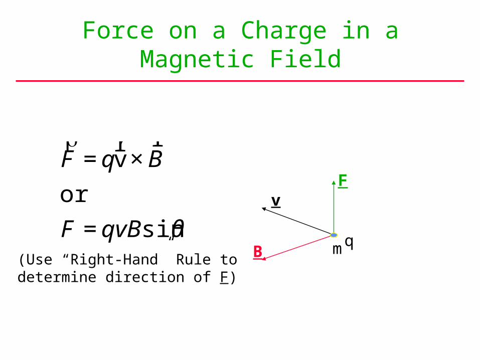
Force on a Charge in aMagnetic Field
€
rF = q
r v ×
r B
or
F = qvBsinθv
F
Bqm
(Use “Right-Hand” Rule to determine direction of F)
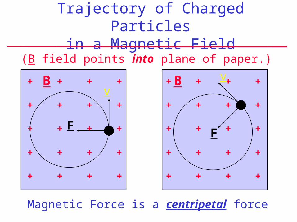
Trajectory of Charged Particlesin a Magnetic Field
+ + + +
+ + + +
+ + + +
+ + + +
+ + + +
+ + + +
+ + + +
+ + + +
+ + + +
+ + + +
vvB B
FF
(B field points into plane of paper.)
Magnetic Force is a centripetal force
+ + + +
+ + + +
+ + + +
+ + + +
+ + + +
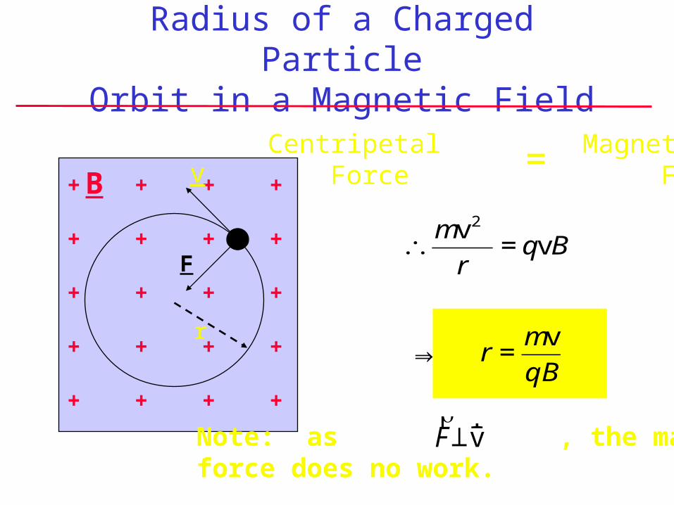
Radius of a Charged ParticleOrbit in a Magnetic Field
vB
F
r
€
∴mv2
r= qvB
⇒ r =mv
qB
Centripetal Magnetic Force Force =
Note: as , the magneticforce does no work.
€
rF ⊥
r v
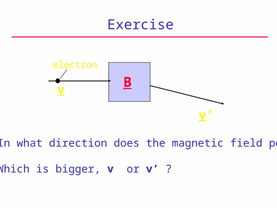
Exercise
Bv
v’
• In what direction does the magnetic field point?
• Which is bigger, v or v’ ?
electron
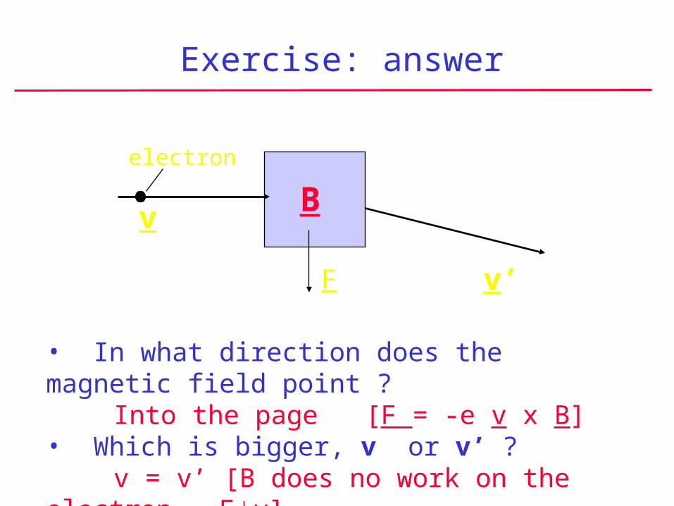
Exercise: answer
Bv
v’
• In what direction does the magnetic field point ?Into the page [F = -e v x B]
• Which is bigger, v or v’ ?v = v’ [B does no work on the electron, Fv]
electron
F
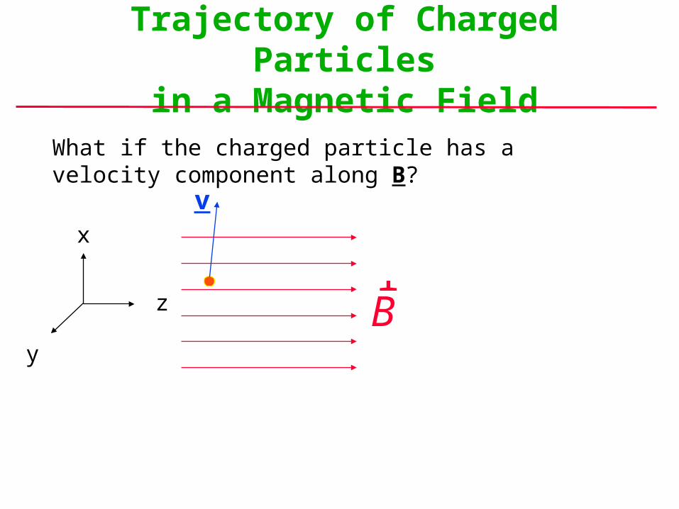
Trajectory of Charged Particlesin a Magnetic Field
What if the charged particle has a velocity component along B?
rBz
x
y
v
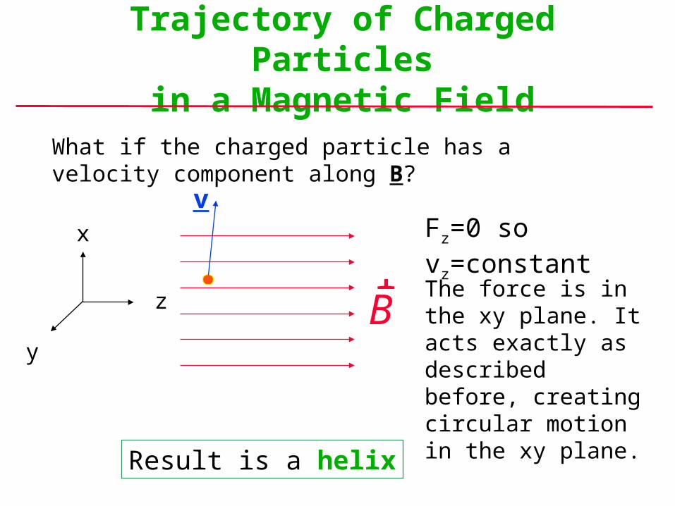
Trajectory of Charged Particlesin a Magnetic Field
What if the charged particle has a velocity component along B?
rB
Fz=0 so vz=constant
The force is in the xy plane. It acts exactly as described before, creating circular motion in the xy plane.
z
x
y
Result is a helix
v
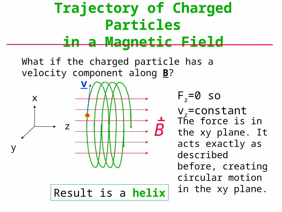
Trajectory of Charged Particlesin a Magnetic Field
What if the charged particle has a velocity component along B?
rB
Fz=0 so vz=constant
The force is in the xy plane. It acts exactly as described before, creating circular motion in the xy plane.
z
x
y
Result is a helix
v
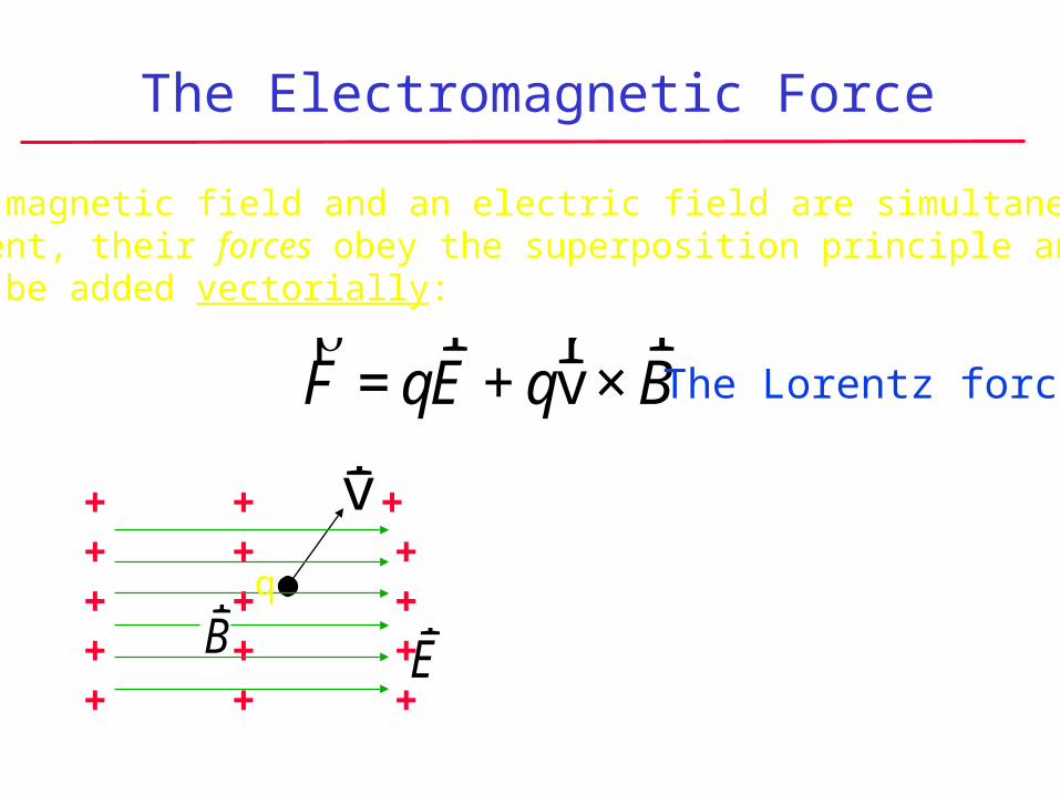
The Electromagnetic Force
If a magnetic field and an electric field are simultaneouslypresent, their forces obey the superposition principle and must be added vectorially:
+ + ++ + ++ + ++ + ++ + +
rv
q
€
rF = q
r E + q
r v ×
r B The Lorentz force
rE
rB
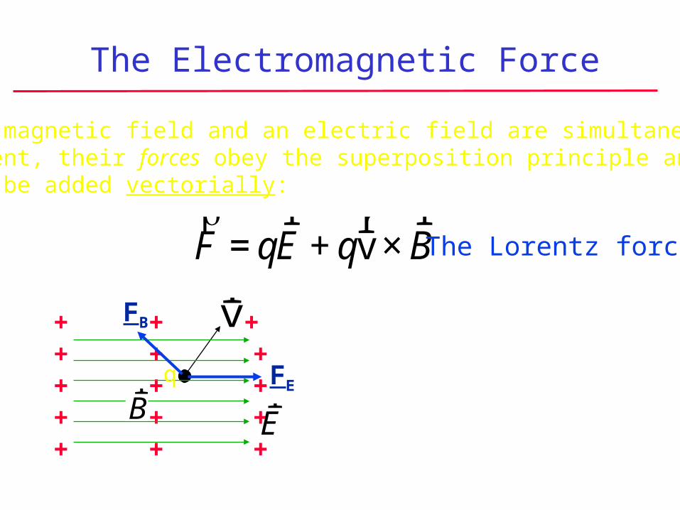
The Electromagnetic Force
If a magnetic field and an electric field are simultaneouslypresent, their forces obey the superposition principle and must be added vectorially:
+ + ++ + ++ + ++ + ++ + +
rv
rE
q
€
rF = q
r E + q
r v ×
r B The Lorentz force
rB
FB
FE
The Electromagnetic Force
+ + ++ + ++ + ++ + ++ + +
rv
rE
rB
FB FE
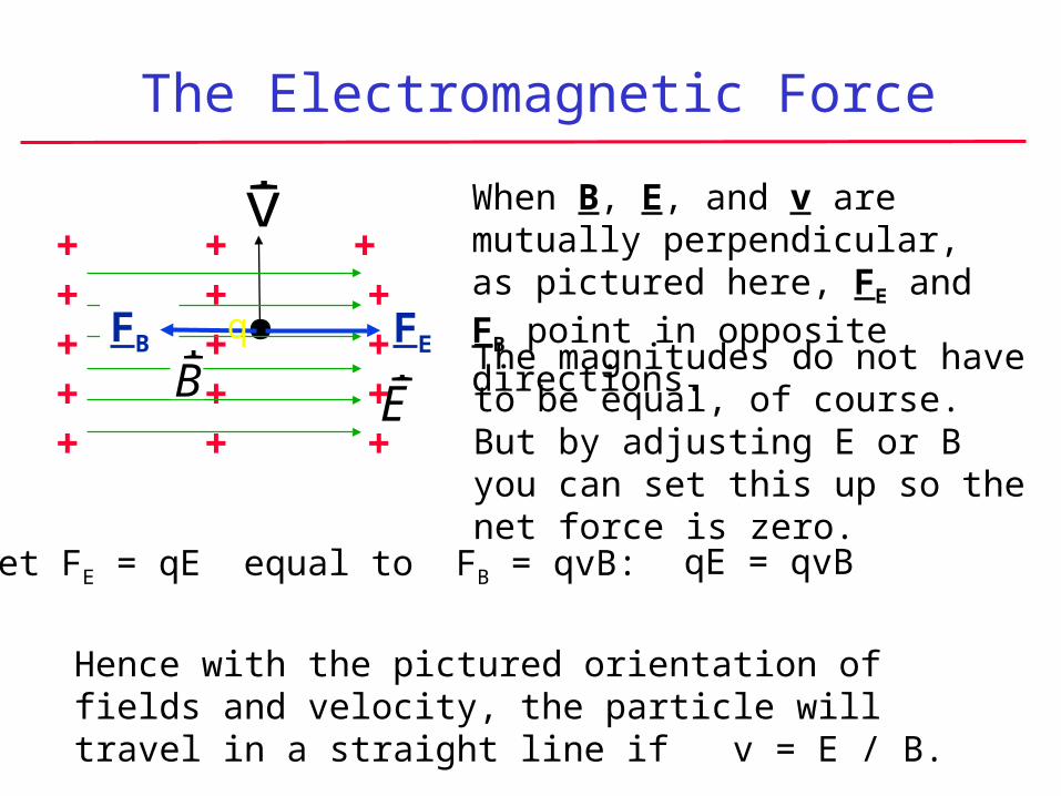
When B, E, and v are mutually perpendicular, as pictured here, FE and FB point in opposite directions.
qThe magnitudes do not have to be equal, of course. But by adjusting E or B you can set this up so the net force is zero.
Set FE = qE equal to FB = qvB: qE = qvB
Hence with the pictured orientation of fields and velocity, the particle will travel in a straight line if v = E / B.
The Hall Effect
I vd
x x x x x x xB
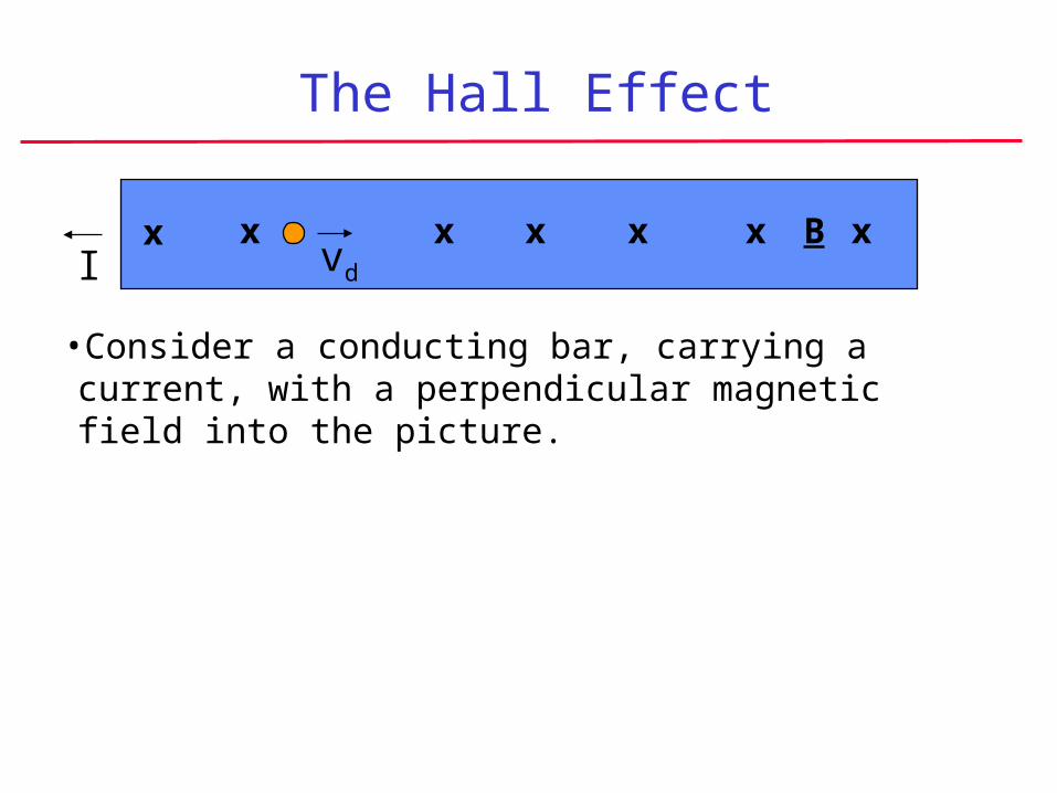
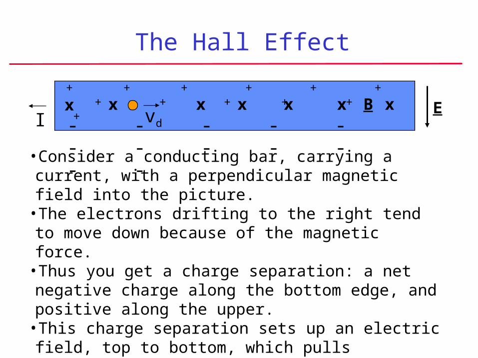
•Consider a conducting bar, carrying a current, with a perpendicular magnetic field into the picture.
The Hall Effect
I vd
x x x x x x xB
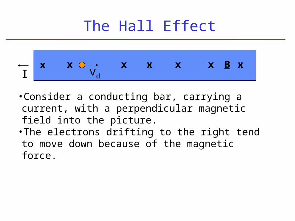
•Consider a conducting bar, carrying a current, with a perpendicular magnetic field into the picture.
•The electrons drifting to the right tend to move down because of the magnetic force.
The Hall Effect
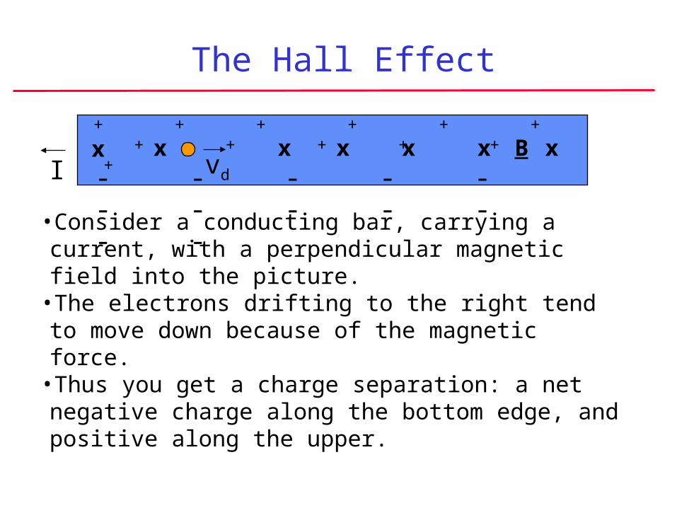
•Consider a conducting bar, carrying a current, with a perpendicular magnetic field into the picture.
•The electrons drifting to the right tend to move down because of the magnetic force.
•Thus you get a charge separation: a net negative charge along the bottom edge, and positive along the upper.
I vd- - - - - - - - - - - -
+ + + + + + + + + + + +x x x x x x xB
The Hall Effect
•Consider a conducting bar, carrying a current, with a perpendicular magnetic field into the picture.
•The electrons drifting to the right tend to move down because of the magnetic force.
•Thus you get a charge separation: a net negative charge along the bottom edge, and positive along the upper.
•This charge separation sets up an electric field, top to bottom, which pulls electrons up – opposing the magnetic force.
I vd- - - - - - - - - - - -
+ + + + + + + + + + + +x x x x x x xB E

The Hall Effect
•Consider a conducting bar, carrying a current, with a perpendicular magnetic field into the picture.
•The electrons drifting to the right tend to move down because of the magnetic force.
•Thus you get a charge separation: a net negative charge along the bottom edge, and positive along the upper.
•This charge separation sets up an electric field, top to bottom, which pulls electrons up – opposing the magnetic force.
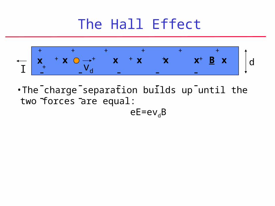
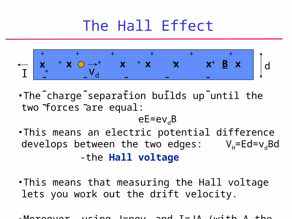
•The charge separation builds up until the two forces are equal:eE=evdB
I vd- - - - - - - - - - - -
+ + + + + + + + + + + +x x x x x x xB E
The Hall Effect
•The charge separation builds up until the two forces are equal:eE=evdB
I vd- - - - - - - - - - - -
+ + + + + + + + + + + +x x x x x x xB d
The Hall Effect
•The charge separation builds up until the two forces are equal:eE=evdB
•This means an electric potential difference develops between the two edges: VH=Ed=vdBd -the Hall voltage
I vd- - - - - - - - - - - -
+ + + + + + + + + + + +x x x x x x xB d
The Hall Effect
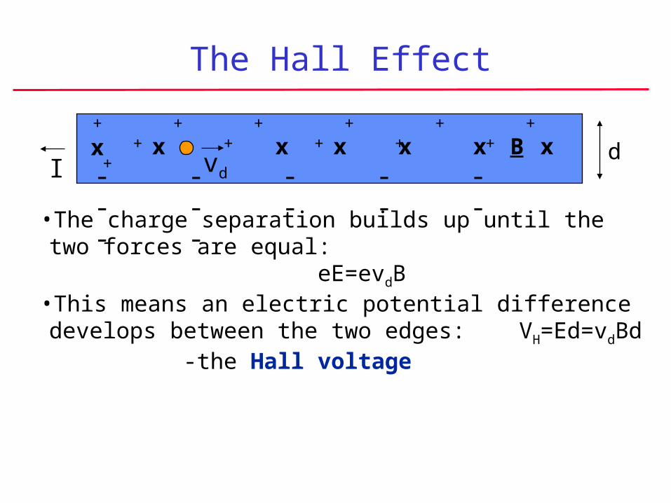
•The charge separation builds up until the two forces are equal:eE=evdB
•This means an electric potential difference develops between the two edges: VH=Ed=vdBd -the Hall voltage
•This means that measuring the Hall voltage lets you work out the drift velocity.
I vd- - - - - - - - - - - -
+ + + + + + + + + + + +x x x x x x xB d
The Hall Effect
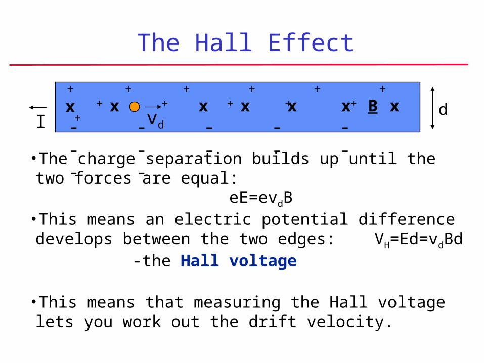
•The charge separation builds up until the two forces are equal:eE=evdB
•This means an electric potential difference develops between the two edges: VH=Ed=vdBd -the Hall voltage
•This means that measuring the Hall voltage lets you work out the drift velocity.
•Moreover, using J=nevd and I=JA (with A the slab’s cross-sectional area) gives vd=I/(Ane) and so VH=IBd/Ane . Measuring the Hall voltage lets you find the density of conduction electrons.
I vd- - - - - - - - - - - -
+ + + + + + + + + + + +x x x x x x xB d
The Hall Effect
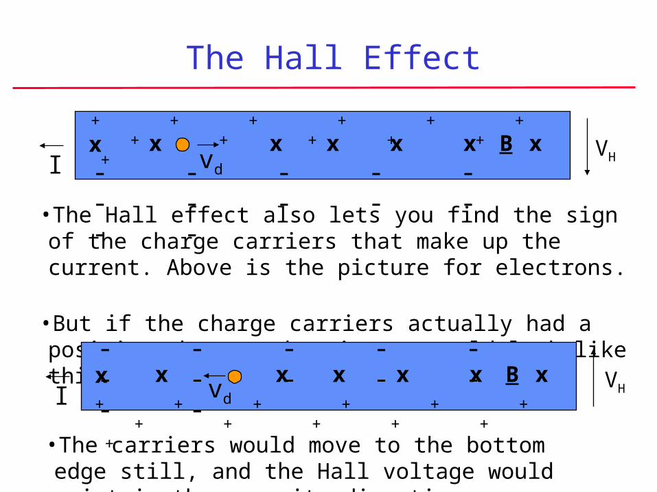
•The Hall effect also lets you find the sign of the charge carriers that make up the current. Above is the picture for electrons.
•But if the charge carriers actually had a positive charge, the picture would look like this:
I vd- - - - - - - - - - - -
+ + + + + + + + + + + +x x x x x x xB VH
I vd
- - - - - - - - - - - -
+ + + + + + + + + + + +
x x x x x x xB VH
•The carriers would move to the bottom edge still, and the Hall voltage would point in the opposite direction.
Magnetic Force on a Current
L
A
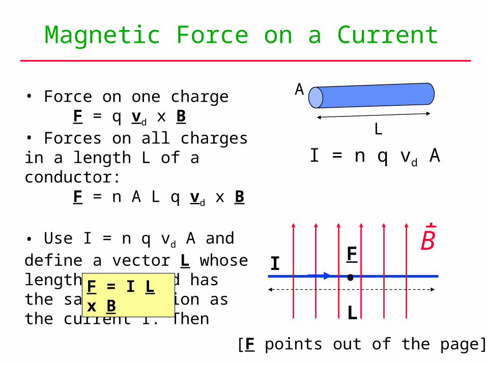
I = n q vd A
• Force on one chargeF = q vd x B
• Forces on all charges in a length L of a conductor:
F = n A L q vd x B
• Use I = n q vd A and define a vector L whose length is L, and has the same direction as the current I. Then
I
rB
L
F
•
[F points out of the page]
F = I L x B

Magnetic Force on a Current
N SI
L
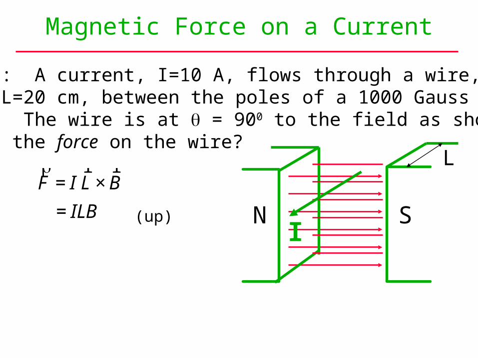
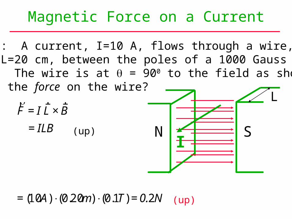
Example: A current, I=10 A, flows through a wire, of length L=20 cm, between the poles of a 1000 Gauss magnet. The wire is at = 900 to the field as shown.What is the force on the wire?
Magnetic Force on a Current
Example: A current, I=10 A, flows through a wire, of length L=20 cm, between the poles of a 1000 Gauss magnet. The wire is at = 900 to the field as shown.What is the force on the wire?
N S
L
(up)I
€
rF = I
r L ×
r B
= ILB
€
rF = I
r L ×
r B
= ILB
= (10A) ⋅(0.20m) ⋅(0.1T) = 0.2N
Magnetic Force on a Current
Example: A current, I=10 A, flows through a wire, of length L=20 cm, between the poles of a 1000 Gauss magnet. The wire is at = 900 to the field as shown.What is the force on the wire?
N S
L
(up)
(up)
I
Magnetic Force on a Current Loop
I
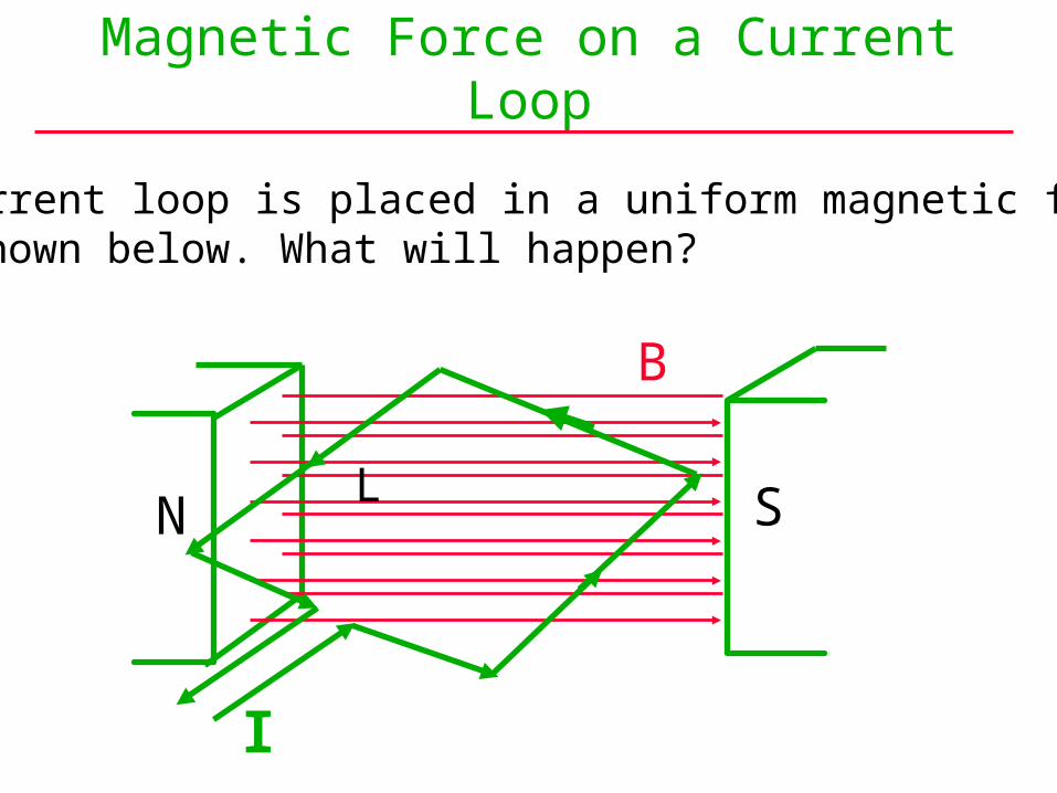
A current loop is placed in a uniform magnetic fieldas shown below. What will happen?
N SL
B
Magnetic Force on a Current Loop
I
N S
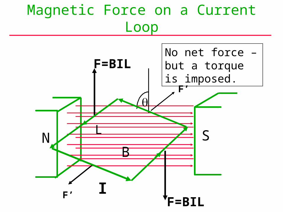
F=BIL
F=BIL
L
F’
F’
B
No net force – but a torque is imposed.
Magnetic Torque on a Current Loop
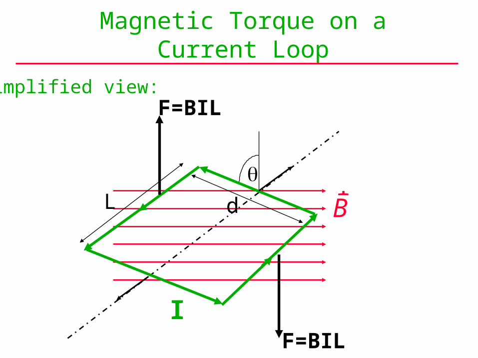
Simplified view:
F=BILI
dL r
B
F=BIL

Simplified view:Torque BIL
d
IAB
= ⋅⎛⎝⎜
⎞⎠⎟⋅
=2
2sin
sin
F=BILI
dL r
B
F=BIL
Magnetic Torque on a Current Loop
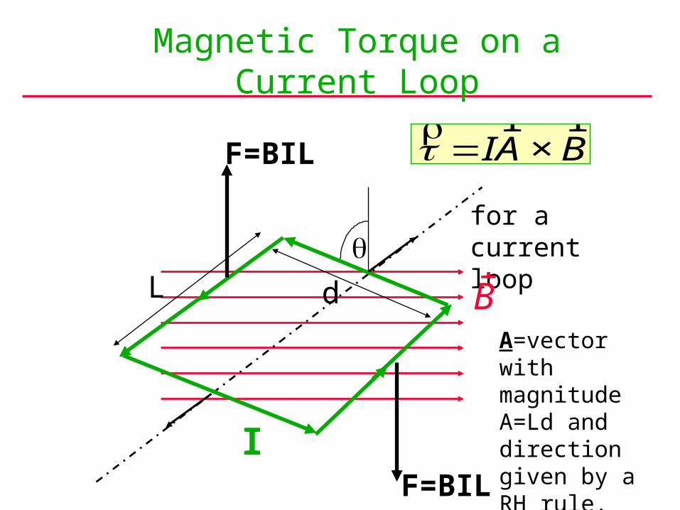
€
rτ =Ir A ×
r B
for a current loop
F=BILI
dL r
B
F=BIL
Magnetic Torque on a Current Loop
A=vector with magnitude A=Ld and direction given by a RH rule.
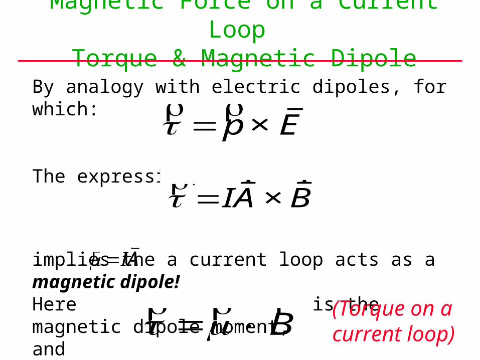
By analogy with electric dipoles, for which:
The expression,
implies the a current loop acts as a magnetic dipole!Here is the magnetic dipole moment, and
Magnetic Force on a Current Loop Torque & Magnetic Dipole
€
rτ =Ir A ×
r B
€
rτ = rp ×
r E
€
rμ =I
r A
€
rτ = rμ × r
B (Torque on acurrent loop)
By further analogy with electric dipoles:
So for a magnetic dipole (a current loop)
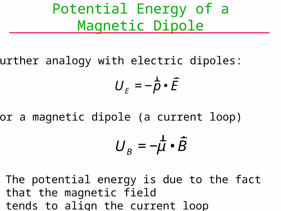
Potential Energy of a Magnetic Dipole
€
UE = −r p •
r E
€
UB = −r μ •
r B
The potential energy is due to the fact that the magnetic fieldtends to align the current loop perpendicular to the field.

Nonuniform Fields and Curved Conductors
• So far, we have considered only uniform fields and straight current paths.
• If this is not the case, we must build up using calculus.
Consider a small length,dL, of current path.
The force on dL is:
dF = dL I x B
rB
I
a
b dF
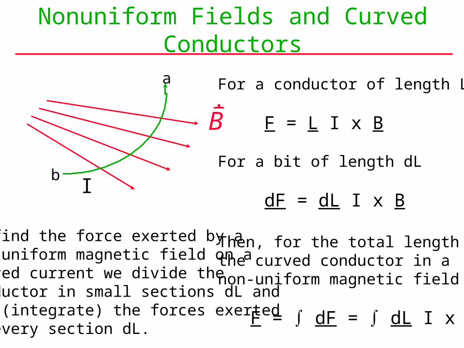
Nonuniform Fields and Curved Conductors
rB
I
a
b
For a conductor of length L
F = L I x B
For a bit of length dL
dF = dL I x B
Then, for the total length ofthe curved conductor in anon-uniform magnetic field
F = dF = dL I x B
To find the force exerted by anon-uniform magnetic field on acurved current we divide the conductor in small sections dL and add (integrate) the forces exertedon every section dL.

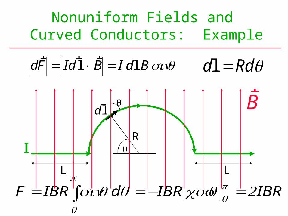
Nonuniform Fields and Curved Conductors: Example
• What is the force on the current-carrying conductor shown?
rB
L L
R
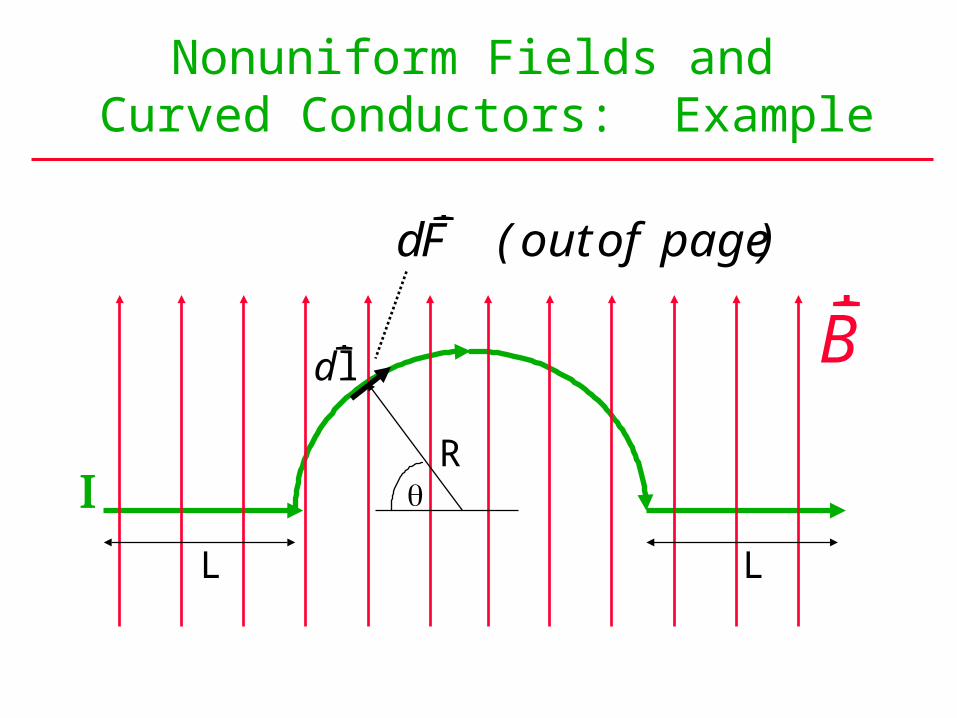
Nonuniform Fields and Curved Conductors: Example
rB
L L
R
drl
dF out of pager
( )
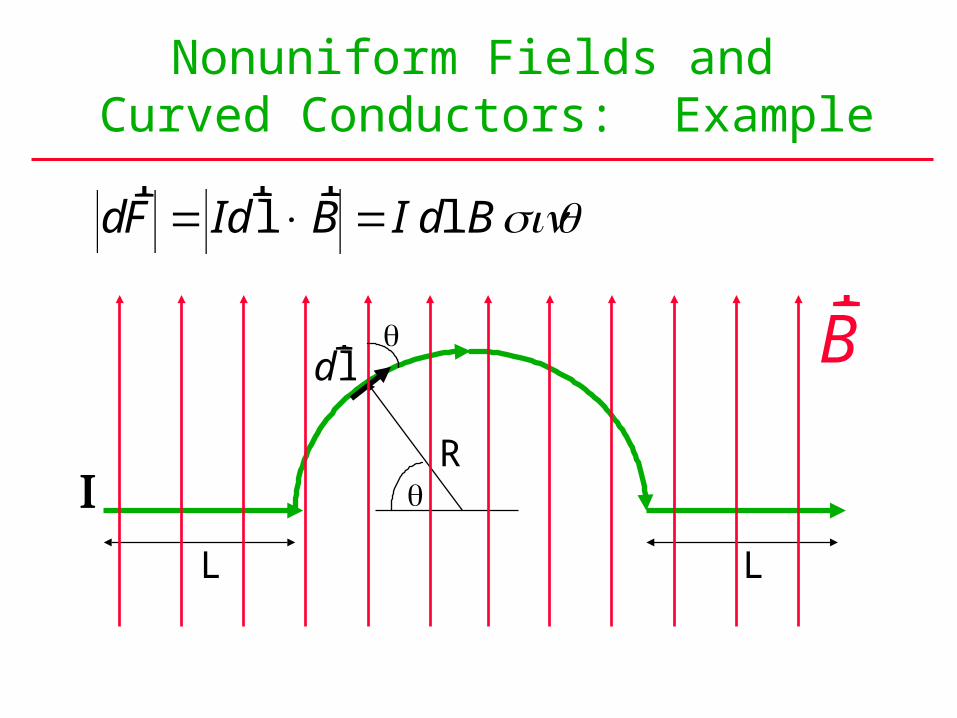
Nonuniform Fields and Curved Conductors: Example
rB
L L
R
drl
dF Id B I d Br r
lr
l= × = sin

Nonuniform Fields and Curved Conductors: Example
dF Id B I d Br r
lr
l= × = sin
rB
L L
R
drl
d Rdl =
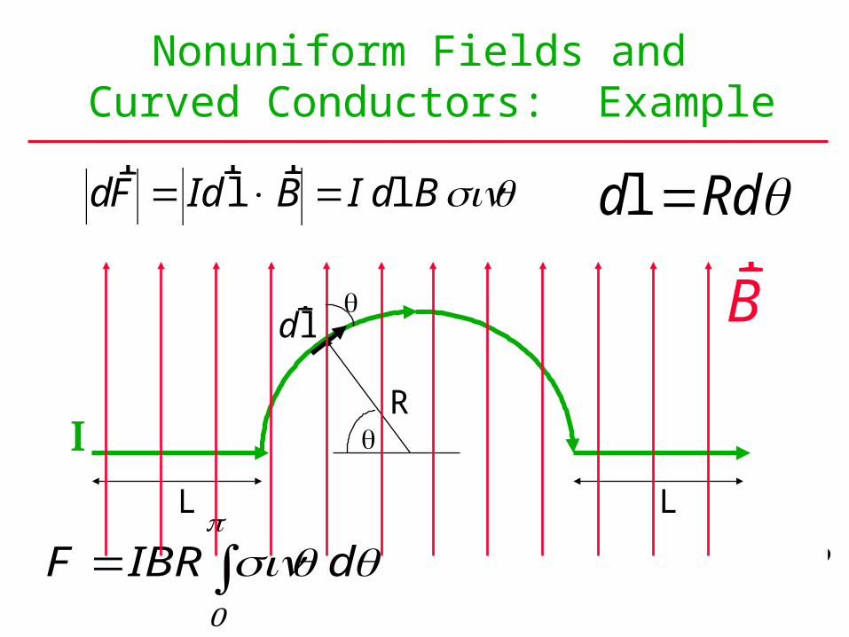
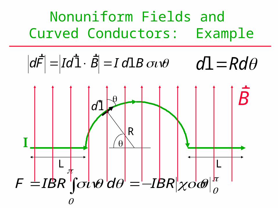
Nonuniform Fields and Curved Conductors: Example
dF Id B I d Br r
lr
l= × = sin d Rdl =
F IBR d IBR IBR= =− =sin cos π
π
00 2
rB
L L
R
drl
Nonuniform Fields and Curved Conductors: Example
dF Id B I d Br r
lr
l= × = sin d Rdl =
F IBR d IBR IBR= =− =sin cos π
π
00 2
rB
L L
R
drl
Nonuniform Fields and Curved Conductors: Example
dF Id B I d Br r
lr
l= × = sin d Rdl =
F IBR d IBR IBR= =− =sin cos π
π
00 2
rB
L L
R
drl
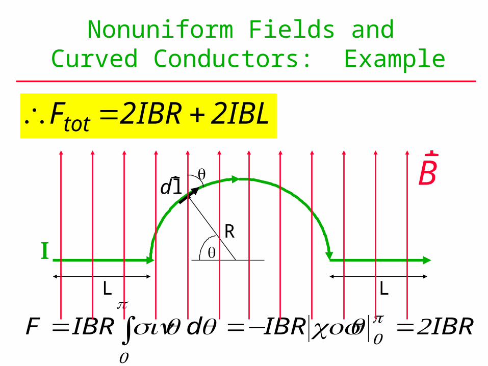
Nonuniform Fields and Curved Conductors: Example
F IBR d IBR IBR= =− =sin cos π
π
00 2
∴ = + = +F IBR IBL IB L Rtot 2 2 2 2( )
rB
L L
R
drl
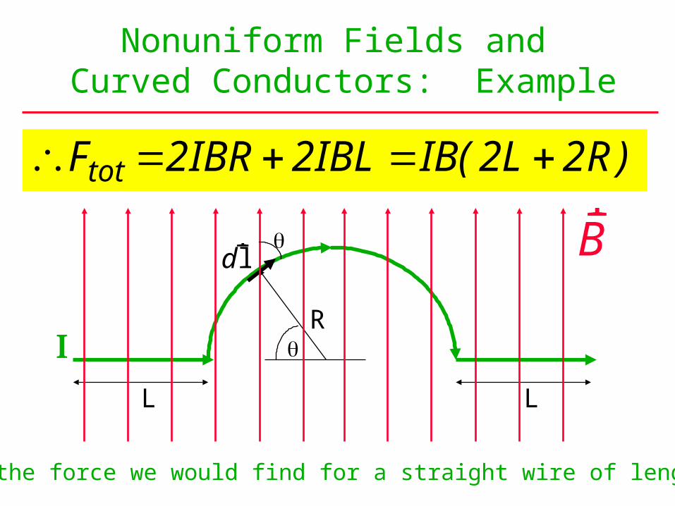
Nonuniform Fields and Curved Conductors: Example
∴ = + = +F IBR IBL IB L Rtot 2 2 2 2( )
Equal to the force we would find for a straight wire of length 2(R+L)
rB
L L
R
drl