Magnetic and electric properties of quantum vacuum - Accueil · teaching and research institutions...
51
HAL Id: hal-00748539 https://hal.archives-ouvertes.fr/hal-00748539 Submitted on 5 Nov 2012 HAL is a multi-disciplinary open access archive for the deposit and dissemination of sci- entific research documents, whether they are pub- lished or not. The documents may come from teaching and research institutions in France or abroad, or from public or private research centers. L’archive ouverte pluridisciplinaire HAL, est destinée au dépôt et à la diffusion de documents scientifiques de niveau recherche, publiés ou non, émanant des établissements d’enseignement et de recherche français ou étrangers, des laboratoires publics ou privés. Magnetic and electric properties of quantum vacuum Rémy Battesti, Carlo Rizzo To cite this version: Rémy Battesti, Carlo Rizzo. Magnetic and electric properties of quantum vacuum. Reports on Progress in Physics, IOP Publishing, 2013, in press. <hal-00748539>
Transcript of Magnetic and electric properties of quantum vacuum - Accueil · teaching and research institutions...
HAL Id: hal-00748539https://hal.archives-ouvertes.fr/hal-00748539
Submitted on 5 Nov 2012
HAL is a multi-disciplinary open accessarchive for the deposit and dissemination of sci-entific research documents, whether they are pub-lished or not. The documents may come fromteaching and research institutions in France orabroad, or from public or private research centers.
L’archive ouverte pluridisciplinaire HAL, estdestinée au dépôt et à la diffusion de documentsscientifiques de niveau recherche, publiés ou non,émanant des établissements d’enseignement et derecherche français ou étrangers, des laboratoirespublics ou privés.
Magnetic and electric properties of quantum vacuumRémy Battesti, Carlo Rizzo
To cite this version:Rémy Battesti, Carlo Rizzo. Magnetic and electric properties of quantum vacuum. Reports onProgress in Physics, IOP Publishing, 2013, in press. <hal-00748539>

Magnetic and electric properties of quantum
vacuum
R. Battesti, C. Rizzo
Laboratoire National des Champs Magnetiques Intenses, 143 avenue de Rangueil,
31400 Toulouse, France.
E-mail: [email protected]
Abstract. In this report we show that vacuum is a nonlinear optical medium and
we discuss what are the optical phenomena that should exist in the framework of the
standard model of particle physics. We pay special attention to the low energy limit.
The predicted effects for photons of energy smaller than the electron rest mass are of
such a level that none has been observed experimentally yet. Progresses in field sources
and related techniques seem to indicate that in few years vacuum nonlinear optics will
be accessible to human investigation.
CONTENTS 2
Contents
1 Introduction 3
2 Theory 4
2.1 General formalism . . . . . . . . . . . . . . . . . . . . . . . . . . . . . . 4
2.2 QED effective lagrangian . . . . . . . . . . . . . . . . . . . . . . . . . . . 7
2.3 Other contributions to the effective lagrangian L . . . . . . . . . . . . . . 12
3 Instruments 12
3.1 Light sources . . . . . . . . . . . . . . . . . . . . . . . . . . . . . . . . . 13
3.2 Electrostatic fields . . . . . . . . . . . . . . . . . . . . . . . . . . . . . . 14
4 Phenomenology and related experiments 15
4.1 Three-wave mixing . . . . . . . . . . . . . . . . . . . . . . . . . . . . . . 16
4.2 Four-wave mixing . . . . . . . . . . . . . . . . . . . . . . . . . . . . . . . 17
4.2.1 Vacuum nonlinear static polarization or magnetization
17
4.2.2 Kerr effect, Cotton-Mouton effect, Jones birefringence, Magneto-
electric birefringence
18
4.2.3 Optical field-induced birefringence
29
4.2.4 Optical rectification induced by electrostatic fields i.e. inverse
magneto-electric effects
30
4.2.5 Optical field induced inverse magneto-electric effects
31
4.2.6 Parametric amplification induced by an electrostatic field : pho-
ton splitting
31
4.2.7 Optical field-induced photon splitting
35
4.2.8 Second harmonic generation induced by an electromagnetic field
: photon fusion
36
4.2.9 Optical field induced photon fusion
36
4.2.10 Intensity dependent refractive index
36
4.2.11 Photon-Photon scattering
37
4.3 Vacuum dichroism . . . . . . . . . . . . . . . . . . . . . . . . . . . . . . 40

CONTENTS 3
4.4 Delbruck scattering . . . . . . . . . . . . . . . . . . . . . . . . . . . . . . 40
5 Phenomenology in astrophysics 41
6 Non trivial vacua 43
7 CP violating vacuum 43
8 Conclusion 44
9 Acknowledgements 44
1. Introduction
Since very ancient times the existence of the vacuum is one of the most fundamental
problems in science. In the Aristotle’s Physics one reads that ”the investigation of
questions about the vacuum must be held to belong to the physicist - namely whatever
it exists or not, and how it exists or what it is”[1]. In his work, Aristotle defines what
is place, time, and vacuum which ”must, if it exists, be place deprived of body”[1].
Following the cyclic evolutions of the concept of vacuum in the history of physics is
out of the scope of this report, but we have at least to define what we intend for vacuum
in the following. We are interested in the electromagnetic properties of vacuum, so our
definition is deeply related to electromagnetism : a vacuum is a region of space in which
a monochromatic electromagnetic plane wave propagates at a velocity that is equal to c.
Following special relativity, this velocity is independent both on the source motion and
on the observer inertial frame of reference. Such a vacuum has not to be empty. For
example in XIX century classical electrodynamics vacuum was supposed to be filled by
the ether. Our definition is essentially a phenomenological one. In principle it provides
a way to test if a region is a vacuum or not.
In classical electrodynamics, vacuum electromagnetic properties are simply
represented by two fundamental constants : the vacuum permittivity ǫ0 and the vacuum
permeability µ0. These constants are linked to the velocity of light in vacuum c thanks
to the fundamental relation c = 1√ǫ0µ0
. They describe respectively the proportionality
factor between D and E and between B and H in vacuum: D=ǫ0E and B=µ0H, where
D is the electric displacement vector, E is the electric field vector, B is the magnetic
induction vector and H is the magnetic field vector. B is also called magnetic field
vector as well as H when there is no risk of confusion [2]. We conform to this common
terminology in the following.
Any variation of the velocity of light with respect to c is ascribed to the fact that
light is propagating in a medium, i.e. not in vacuum. To describe such a phenomenon
one introduces the constants ǫ and µ which characterize the medium itself: D=[ǫ] E
and B=[µ] H. The velocity of light in a medium is smaller than the velocity of light in
vacuum by a factor n, the index of refraction, equal to n =√ǫµ√
ǫ0µ0
. Vacuum is therefore
CONTENTS 4
the medium to which in classical electrodynamics one associates an index of refraction
n exactly equal to 1 and therefore in vacuum ǫǫ0
= 1 and µ
µ0
= 1.
Since the half of XIX century, when Faraday discovered that an external magnetic
field could change the polarization of light propagating in matter because of a
magnetically induced circular birefringence [3], it is known that the presence of
electrostatic fields induces a response from the medium which depends on the field
strength. This means that ǫ and µ are not constants but functions of the external
fields. In 1961 the second harmonic generation experiment of Franken et al. [4] opened
up the field of nonlinear optics. In general, it deals with nonlinear interactions of light
with matter including light and/or external electromagnetic field induced changes of the
optical properties of a medium [5]. All media are basically nonlinear and thus ǫ and µ
can be written as ǫ(E,B) and µ(E,B) where E and B are the total electromagnetic fields
both external and associated to the electromagnetic waves propagating in the medium.
Therefore in general n depends also on E and B, n(E,B).
In this report we show that vacuum can be considered as a nonlinear optical medium
and we discuss what are the optical phenomena that should exist in the framework of the
standard model of particle physics. Our work is mainly devoted to the phenomenological
manifestations of these quantum vacuum non linearities. We classify all the expected
phenomena following nonlinear optics textbooks. We pay special attention to the low
energy limit since this limit is sufficient to understand most of the attempted and
proposed experiments. While the corresponding theory is almost a century old, the
predicted effects for photons of energy smaller than the electron rest mass are of such
a level that none has been observed experimentally yet. Progresses in field sources and
related techniques seem to indicate that in few years vacuum nonlinear optics will be
accessible to human investigation.
2. Theory
2.1. General formalism
In a medium the excitation due to light and external fields produces a polarization P
and a magnetization M. Both of them depend on the electromagnetic fields and hence
the response of the medium to the excitation is nonlinear. For describing this nonlinear
interaction, one uses the constitutive equations of the medium giving the relationship
between P and (E,B) and between M and (E,B), and Maxwell’s equations [5]. When
no charge density or current density are present, Maxwell’s equations can be written in
SI units [2] as
∇× E = − ∂B
∂t,
∇×H =∂D
∂t, (1)
∇ ·D = 0,

CONTENTS 5
∇ ·B = 0,
with
H =1
µ0
B−M,
D = ǫ0E+P. (2)
Thanks to Maxwell’s equations one can fully determine wave propagation.
The constitutive equations can be obtained by the following relations [6]:
D =∂L
∂E, (3)
H = − ∂L
∂B, (4)
where L is the effective lagrangian representing the interaction of electromagnetic
fields in vacuum.
The mathematical expression of the effective lagrangian L is essentially determined
by the fact that it has to be relativistic invariant and therefore it can only be a function
of the Lorentz invariants F and G [6] :
F =
(
ǫ0E2 − B2
µ0
)
, (5)
G =
√
ǫ0µ0
(E ·B). (6)
The general expression can be therefore written as
L =∞∑
i=0
∞∑
j=0
ci,jFiGj. (7)
The lowest order terms must give the classical Maxwell lagrangian L0 = 12F , thus
c0,0 = 0, c1,0 =12and c0,1 = 0.
Using the relations (3) and (4) one obtains
D =∞∑
i=0
∞∑
j=0
ci,j
(
iF (i−1)Gj ∂F
∂E+ jG(j−1)F i∂G
∂E
)
=∞∑
i=0
∞∑
j=0
ci,j
(
2ǫ0iF(i−1)GjE+ j
√
ǫ0µ0
G(j−1)F iB
)
, (8)
H =∞∑
i=0
∞∑
j=0
−ci,j(
iF (i−1)Gj ∂F
∂B+ jG(j−1)F i∂G
∂B
)
=∞∑
i=0
∞∑
j=0
ci,j
(
2iF (i−1)Gj B
µ0
− j
√
ǫ0µ0
G(j−1)F iE
)
, (9)

CONTENTS 6
which at the lowest orders gives
D = 2ǫ0c1,0E+
√
ǫ0µ0c0,1B+ 2ǫ0c1,1GE+
√
ǫ0µ0c1,1FB+ 4ǫ0c2,0FE
+ 2
√
ǫ0µ0c0,2GB, (10)
H = 2c1,0B
µ0−√
ǫ0µ0c0,1E+ 2c1,1G
B
µ0−√
ǫ0µ0c1,1FE+ 4c2,0F
B
µ0
− 2
√
ǫ0µ0c0,2GE. (11)
The classical equations D = ǫ0E and H = B
µ0are recovered at the lowest order in
the fields by imposing c1,0 =12and c0,1 = 0.
In the case of a plane wave propagating in a vacuum, both F and G are equal to
zero and therefore L = 0 as well. This means that, because of Lorentz invariance, the
propagation of a plane wave in vacuum cannot be affected by any nonlinear interactions.
It can be shown that L is also equal to 0 in the case of two copropagating (k1 = k2)
plane waves of different polarization (E1 6= E2). The simplest cases in which L 6= 0,
giving rise to nonlinear effects in vacuum, are the one of a plane wave propagating in
the presence of external static electric or magnetic fields (E0, B0), and the one of two
plane waves of the same polarization (E1 = E2) of different wavevectors (k1 6= k2).
This is true in particular for counterpropagating plane waves (k1 = −k2).
It is worth stressing that, as far as Lorentz invariance holds, our phenomenological
definition of a vacuum also holds even in the presence of nonlinear interactions. A plane
wave velocity different from c can be ascribed to the presence of matter, as in classical
electrodynamics, and/or to the presence of electromagnetic fields.
Since L can only be a sum of terms containing powers of F and G, lagrangian
terms containing a product of an odd number of electromagnetic fields are not allowed
in vacuum (see eq. 7). This means that not all the nonlinear effects existing in a
standard medium exist in vacuum. The form of lagrangian L also indicates that the
B field and the E field of waves play an equivalent role as far as nonlinear effects in
vacuum are concerned. In standard media B field is usually neglected and all the effects
are ascribed to an ǫ function only of E while µ is assumed equal to µ0 [5]. In this sense
a vacuum can be considered as a magnetic medium.
Finally, the energy density U can be written as [6]
U = E∂L
∂E− L
=∞∑
i=0
∞∑
j=0
ci,j(
2ǫ0iF(i−1)GjE2 + (j − 1)F iGj
)
. (12)

CONTENTS 7
Taking into account that c0,0 = 0, c1,0 = 12and c0,1 = 0, the term (i = 1, j = 0)
gives the classical energy density U0.
U0 =1
2
(
ǫ0E2 +
B20
µ0
)
. (13)
This expansion of the electromagnetic energy density in vacuum can be compared
with the one given by Buckingham [7] in the case of a molecule in the presence of external
electromagnetic fields. One can find a direct correspondence between vacuum terms and
the molecular ones, showing once more that vacuum behaves as a standard medium.
In the case of molecular energy density each term represents a specific microscopical
property of a single molecule, like polarizability, while for vacuum we are dealing with
macroscopical properties. To pass from microscopical to macroscopical properties in the
case of molecules one has to take into account the molecular density, a concept that has
no equivalence for vacuum.
In the different theoretical frameworks one can find predictions for the ci,jcoefficients introduced in Eq. (7). Quantum electrodynamics (QED) provides the most
complete theoretical treatment.
2.2. QED effective lagrangian
In 1933 the calculations of gamma rays absorption due to the formation of electron-
positron pairs by Oppenheimer and Plesset [8] gave a striking confirmation of Dirac’s
theory of the positron as holes in a sea of negative energy states setting up a new picture
of the vacuum in which all the negative energy states are occupied and all the positive
energy states are unoccupied. Dirac gives a clear overview of his model in his 1934
contribution to the Solvay workshop [9]. It was immediately clear that an important
prediction of Dirac’s theory, which could in principle be experimentally tested, was the
existence of photon-photon scattering [10], [11].
A first theoretical formulation of optical non linearities in vacuum at the lowest
orders in the electromagnetic fields has been published in 1935 by Euler and Kochel
[12]. The details about their calculation can be found in ref. [13]. In the 1936 paper
by Heisenberg and Euler [14] a complete theoretical study of the phenomena related
to the fact that electromagnetic radiation can be transformed into matter and vice
versa can be found. The authors starting point was that it was no more possible to
separate processes in the vacuum from those involving matter since electromagnetic
fields can create matter if they are strong enough. Moreover, even if they are not strong
enough to create matter, they polarize the vacuum because of the virtual possibility of
creating matter, essentially with electron-positron pairs, and therefore they change the
constitutive equations [14].
The resulting effective lagrangian of the field reads [14]:
LHE =1
2
(
ǫ0E2 − B2
µ0
)
+ α∫ ∞
0e−η dη
η3(14)

CONTENTS 8
×
iη2√
ǫ0µ0
(E ·B)cos
(
η√ǫ0Ecr
√C)
+ conj.
cos(
η√ǫ0Ecr
√C)
− conj.+ ǫ0E
2cr +
η2
3(ǫ0E
2 − B2
µ0
)
,
with C =
(
ǫ0E2 − B2
µ0
)
+ 2iǫ0µ0
(E ·B),
where α = e2
4πǫ0hcis the fine structure constant, e the elementary charge, h the
Planck constant h divided by 2π, and η is the integration variable. Ecr = m2ec
3
ehis a
quantity obtained by combining the fundamental constant me, the electron mass, with
c, e and h. Ecr has the dimensions of an electric field, and it is called the critical electric
field. Its value is Ecr = 1.3× 10¹⁸ V/m. It corresponds to the field one needs to get an
energy eEcrL equal to an electron rest mass mec2 over a length L equal to the reduced
electron Compton wavelength λ = λe
2π= h
mec.
A critical magnetic field can also be defined in the same manner, Bcr =Ecr
c= m2
ec2
eh.
Bcr = 4.4 × 10⁹ T. The cyclotron pulsation for an electron in a Bcr field, ωc =eBcr
m, is
such that the associated energy hωc is equal to its rest mass mec2.
LHE is valid in the approximation that the fields vary very slowly over a length equal
to the reduced electron Compton wavelength during a time te =λcwhich corresponds
to:
h
mec|∇E(B)| ≪ E(B), (15)
h
mec2|∂E(B)
∂t| ≪ E(B). (16)
A study of the vacuum electrodynamics based on the quantum theory of the electron
can also be found in the 1936 paper by Weisskopf [15] in which a simplified method to
obtain LHE is shown.
In general QED lagrangian LHE can be expanded as indicated in Eq. (7). Thanks
to the symmetry properties of the E and B fields (see table 1), F and G are also CPT
invariant, but while F is C, P, and T invariant, G violates P and T.
C P T CPT
E - - + +
B - + - +
F + + + +
G + - - +
Table 1. Symetry properties on the electromagnetic fields
As the QED quantum vacuum is assumed to be C, P, T invariant, one has to take
into account that all the coefficients ci,j with an index j corresponding to an odd number
are null, and in particular c0,1 = 0 and c1,1 = 0.
CONTENTS 9
At the lowest orders in the fields, i.e. E ≪ Ecr and B ≪ Bcr, LHE can be written
as LHE = L0 + LEK where LEK has been first calculated by Euler and Kockel in 1935
[12]. LEK can be written as LEK = c2,0F2 + c0,2G
2
The value of c2,0 and c0,2 can be written following the Euler-Kochel result [12] as :
c2,0 =2α2h3
45m4ec
5=
α
90π
1
ǫ0E2cr
=α
90π
µ0
B2cr
≃ 1.67× 10⁻³⁰
[
m3
J
]
, (17)
c0,2 = 7c2,0, (18)
and therefore
LEK =2α2h3
45m4ec
5ǫ20[(E
2 − c2B2)2 + 7c2(E ·B)2]. (19)
Next term coefficients can be found in [14], [15] and [16].
c3,0 =32πα3h6
315m8ec
10=
2α
315π
1
ǫ20E4cr
=2α
315π
µ20
B4cr
≃ 6.2× 10−56
[
m6
J2
]
, (20)
c1,2 =13
2c3,0, (21)
c4,0 =3568π2α4h9
945m12e c
15=
223α
3780π
1
ǫ30E6cr
=223α
3780π
µ30
B6cr
≃ 4.4× 10−80
[
m9
J3
]
,(22)
c2,2 =402
223c4,0, (23)
c0,4 =304
223c4,0. (24)
Following the developments in QED of the forties by Tomonaga, Schwinger,
Feynman and Dyson [17], a quantum field theory has been fully established and the
Dirac’s model of vacuum has become somewhat an obsolete and unnecessary concept.
In the field theory perspective, vacuum becomes the ground state of the quantum
field. This theoretical definition of a vacuum is in agreement with ours which refers
to macroscopical phenomenological electromagnetic properties like ǫ and µ [18].
A modern confirmation of Euler and Kochel result has been given by Karplus
and Neuman in 1950 [19], and the Heisenberg-Euler lagrangian has been validate by
Schwinger in 1951 [20]. The lowest order in the nonlinear effect given by the Euler-
Kochel lagrangian can be represented by the Feynman diagram of Fig. 1 [19].
An analytic form for the Heisenberg-Euler lagrangian can be found in ref. [21], but
for most of the practical cases, effects can be calculated using first terms given by LEK .
In fact eq. (14) can be expanded in terms of reduced Lorentz invariants F ′ and G′
F ′ =
(
E2
E2cr
− B2
B2cr
)
, (25)
G′ =
(
E
Ecr
· B
Bcr
)
, (26)

CONTENTS 10
Figure 1. Feynman diagram for the lowest order in the nonlinear effect in vacuum.
Solid circular lines represent the electron-positron loops, wavy lines the photons and
wavy lines with cross ending the external fields.
which means that higher and higher order terms corresponding to higher and higher
powers of F ′ and G′ give smaller and smaller contributions when EEcr
and BBcr
are much
smaller than 1.
After 75 years the impact of Heisenberg-Euler lagrangian in fundamental physics
is still very important as discussed in ref. [22]. Our review is essentially based on its
predictions.
Heisenberg-Euler lagrangian does not take into account all the microscopic
phenomena related to the photon-photon interaction in vacuum. Corrections to the
value of the coefficients ci,j obtained using LHE can be calculated taking into account
the change induced by the external fields in the radiative interactions of the vacuum
electrons. In particular Ritus [23] has published in 1975 the corrections to c2,0 and c0,2.
The lowest order radiative corrections can be represented by the Feynman diagram of
Fig. 2,
Figure 2. The Feynman diagram corresponding to the lowest order radiative
corrections.
and the corresponding effective lagrangian can be written following [23] as
LR =α3h3
81πm4ec
5
(
16F 2 +263
2G2)
, (27)
which gives a 1.0% correction to c2,0:
cR2,0 =2α2h3
45m4ec
5
(
1 +40α
9π
)
(28)
CONTENTS 11
and a 1.2% correction to c0,2:
cR0,2 =14α2h3
45m4ec
5
(
1 +1315α
252π
)
. (29)
The Ritus corrections to c2,0 and c0,2 are about α times smaller than the Euler-
Kochel values for these two coefficients. Nevertheless, these corrections are more
important than the next terms in the expansion of LHE corresponding to the coefficients
c1,2, c3,0 when E ≪ Ecr and B ≪ Bcr.
Following Eq. (12), the energy density U when E ≪ Ecr and B ≪ Bcr can be
written as [15]:
U =1
2
(
ǫ0E2 +
B2
µ0
)
+ c2,0
(
ǫ0E2 − B2
µ0
)(
3ǫ0E2 +
B2
µ0
)
+ c0,2ǫ0µ0
(E ·B)2 + c3,0
(
ǫ0E2 − B2
µ0
)2 (
5ǫ0E2 +
B2
µ0
)
(30)
+ c1,2ǫ0µ0
(E ·B)2(
3ǫ0E2 − B2
µ0
)
.
Using the relations (10), (11) and (2) one obtains the polarization and the
magnetization of the vacuum at the lowest orders in the fields :
P = 4c2,0ǫ0EF + 2c0,2
√
ǫ0µ0
BG, (31)
M = −4c2,0B
µ0F + 2c0,2
√
ǫ0µ0
EG. (32)
In principle, since electromagnetic fields have self-interactions one should calculate
the corrections to the Maxwell classical solutions for any distribution of charges and
currents [24].
The corrections to the Coulomb potential of a charge induced by vacuum
polarization have been calculated in 1935 by Uehling [25] together with the
corresponding displacement of atomic energy levels. This is a fundamental result for
the QED of bound states.
The case of a magnetic dipole has been treated in ref. [26] where the field equations
of a static magnetic field have been considered and the field of the dipole has been
calculated taking into account one-loop QED corrections.
The value of the lowest order coefficients c2,0 and c0,2 depends on the fourth power of
the inverse of the electron mass me. Following ref. [20] one can generalize Heisenberg-
Euler result to any spin 12charged field like the one corresponding to negative and
positive muons. For the sake of comparison, one can consider that the value of Bcr sets
the relative scale of different contributions coming from different fermions. The critical
magnetic field for muon leptons is about 1.9 × 10¹⁴ T and for tau leptons 5.3 × 10¹⁶ T.
The contributions coming from muon or tau fields are usually neglected.

CONTENTS 12
2.3. Other contributions to the effective lagrangian L
The effective lagrangian L is valid in the approximation of constant or slowly varying
electromagnetic fields. As the available laser pulse intensity increases and pulse time
width decreases, one needs in principle to take into account the dispersive corrections
of L. This means that one has to take into consideration a correction to L depending
on the derivatives of electromagnetic fields. How to treat dispersion and absorption in
the lagrangian formalism is a debated question and it has generated a large literature to
correctly describe quantum electromagnetism in dielectric media. From this literature
it is worth mentioning the two recent works of Huttner and Barnett [27], and Philbin
[28].
As far as quantum vacuum is concerned, the authors of ref. [29] give the effective
lagrangian corresponding to dispersion corrections and they derive in the low energy
limit (hω ≪ mec2) the vacuum dispersion relation:
ω ≃ ck(
1− 1
2ζQ2 − σζ2Q4k2
)
, (33)
where ζ depends on light polarization and it is equal to 4c2,0 or 2c0,2, σ = 2αh2
15m2ec
2 is
a parameter corresponding to the dispersive properties of the polarized vacuum. Its
numerical value is about 1.4 × 10⁻²⁸ m2 and Q is a parameter depending on the
electromagnetic fields. For electromagnetic fields perpendicular to the light wavevector
k, Q can be written as
Q2 = ǫ0E2 +
B2
µ0− 2
√
ǫ0µ0
(E×B). (34)
The first two terms of eq. (33) correspond to a linear dispersion relation representing
a vacuum velocity of light that depends slightly on the light polarization. This is an
important point that will be treated in details in the following paragraphs. The third
term is the nonlinear term coming from the dispersive correction to L. Its order of
magnitude can be estimated as 8 × 10−86Q4k2, and it seems very challenging to detect
in a laboratory [29].
In the framework of the standard model, contributions others than QED ones
appears essentially at the QCD scale and at the electroweak scale. QCD scale can
be associated to a mass ΛQCD ≃ 200 MeV close to the mass of the pion π± meson. The
corresponding critical magnetic field BQCDcr is of the order of 1015 T [30]. Electroweak
scale can be associated to the mass of the W± boson which is about 80 GeV . The
corresponding critical magnetic field BEWcr is of the order of 1020 T[30]. It is obvious that
these contributions can be neglected most of the time and there is not much literature
about them.
3. Instruments
The experimental tests of the Heisenberg-Euler lagrangian need high magnetic or electric
fields. In this section, we give a short overview of the existing solutions for producing

CONTENTS 13
such intense fields.
3.1. Light sources
Since 1960 and the invention of the laser by Maiman [31], the available intensity has
jumped to highest and highest levels. Today, a number of exawatt (1018 W) class
facilities are already in the planning stage (ELI program in Europe [32], Exawatt
Laser in Japan [33] for example). High power lasers are expected to approach in the
future the Schwinger limit corresponding to an intensity Is ≈ 1033 W.m−2. At such
a level the electric field Eω associated to the wave is of the order of the critical one,
Eω =√
Is2ǫ0c
≈ Ecr, which allows the creation of real e−e+ pairs from the vacuum [20].
All facilities around the world are nowadays based on the Chirped Pulse
Amplification (CPA) proposed by G. Mourou in 1985 [34]. Since then the available
laser power has increased rapidly. Basically, high powers are limited by the damage
threshold of materials which typically lies around 104 GW.m−2. The problem thus is
to amplify a short pulse without reaching this damage intensity. The principle of the
CPA is the following (see fig. (3)) : a short laser impulsion is temporally stretched
before being amplify up to 104 GW.m−2. Then the pulse is temporally recompressed
before being focused on a target. In this way, one can amplify the intensity (expressed
in J.s−1.m−2) of the pulse without decreasing its fluency (expressed in J.m−2).
The Extreme Light Infrastructure (ELI) project represents one of the largest laser
project in the world. Its goal is to produce a few kJ of energy in 10 fs, which means
more than 1014 W of power with a target intensity of 1030 W.m−2 [32]. As far as we
know, the highest intensity ever reached nowadays is 2 × 1026 W.m−2 [35] with the
HERCULES petawatt facility [36] in the USA.
Two ambitious projects are also in progress, the National Ignition Facility, USA
[37] and the laser Megajoule, France [38], in order to create fusion ignition in laboratory.
Both of them will be able to fire an energy of about 1,8 MJ thanks to the amplification
of more than 200 laser beams.
amplification compressionpulse temporally strech
Figure 3. Chirped Pulse Amplification technique (CPA). A short laser pulse is
temporally streched. After this operation the fluency (J/m2) is the same as before
but the intensity is reduced. Then the pulse can be amplified without risk for the
optical materials. When the desired energy is achieved, the pulse is recompressed to
reach high intensities.
For smaller intensities, commercial sources are also available. For example, one can
buy table top sources which deliver more than 100 TW (2.5 J in 25 fs). A laser beam of

CONTENTS 14
this kind focused on a 10−6 m2 spot gives an intensity of 1020 W.m−2 which corresponds
to an energy density ǫ0E2ω + B2
ω/µ0 such that the electric field Eω is about 1.36 × 10¹¹
V/m and the magnetic field Bω is about 4.5 × 10² T. These values are of the order of
the highest static fields ever obtained in laboratories, and therefore intense lasers can
also be used as sources of electromagnetic fields to induce nonlinear optics effects. We
label this kind of effects with the optical field induced prefix in their name.
3.2. Electrostatic fields
In principle, the external fields needed for experiments can be either magnetic or electric.
In vacuum the same level of effect is obtained in the presence of a B field or an electric
field E equal to cB. This means that to equalize an effect created by a magnetic field
of 1 T, one has to use an electric field of 300 MV/m. It looks like that, from the
technological point of view, magnetic fields of several Tesla are easier to produce than
electric fields of about 1 GV/m. Experimentalists have therefore mostly concentrated
their efforts to magnetically induced effects in vacuum.
To produce a magnetic field, the standard method is to let a current circulate in a
coil. The obtained magnetic field is proportional to the current density. This current
density creates also a force density which is proportional to the product of the current
density and the magnetic field and hence to the square of the magnetic field. Moreover,
the current creates losses in the conductors by Joule effect and it heats the system.
These two effects have to be taken into account to reach high magnetic fields.
Several solutions exist. One is to avoid heating thanks to superconducting wires.
This is the solution chosen at CERN for example for the Large Hadron Collider magnets
[39]. The maximum field achievable depends on the critical fields of the materials
above which the superconductivity property disappears. Magnets around 20 T are
commercially available.
Another solution is to remove the dissipate electrical energy. It can be done with
water. By this way, one can achieve magnetic field up to 35 T but one needs a big
electrical installation of several tens mega watts. Only a few installations around
the world have installed this electrical power : NHMFL-DC (Tallahassee, USA) [40],
LNCMI-G (Grenoble, France) [41], HFML (Niemegen, Neetherland) [42], HMFL (Hefei,
China) [43], TML, (Tsukuba, Japan) [44]. A third way is to produce magnetic field with
a combination of the two last methods : superconducting and copper wires cooled with
water. The actual record of this kind of coils is 45 T during one hour.
Another way to avoid the problem of heating is to use pulsed fields. The idea
is to discharge a lot of energy during a small duration in a coil. In this way, one can
reach 80 T in 10-100ms depending on the available bank of capacitors which delivers the
energy. Up to date, the world record has been reached at the NHMFL-PF in Los Alamos
in the United States with 100 T. The main worldwide pulsed field installations are
NHMFL-PF (Los Alamos, USA) [45], LNCMI-T (Toulouse, France) [46], HLD (Dresden,
Germany) [47], HFML (Niemegen, Neetherlands) [42], WHMFC (Wuhan, China) [48],
CONTENTS 15
TML (Tsukuba, Japan) [44]. The limitation of these pulsed coils is a combination of
heating and magnetic pressure which can reach intensities of 109 Pascal.
To go further and to reach 300 T in a few microseconds, a possibility is given by a
single turn coil. This is called megaGauss installation and only 2 are operational around
the world (Toulouse and Tokyo) (see e.g. [49]). In this experiment, a single turn coil is
placed at the end of a generator which delivers more than 60 000 A in one microsecond.
After a few microseconds the coil is destroyed but this duration is enough to perform
optical measurements.
More recently, the LNCMI Toulouse has developed special coils and generators for
bringing high magnetic fields to special external installations like particle accelerator
facilities or intense laser facilities. The generators are transportable and then high
magnetic fields can move almost everywhere (see e.g. [50]).
The highest fields of which we have discussed previously are longitudinal magnetic
fields. This means that the magnetic field is parallel to the optical access like in the case
of simple solenoids [2] : this is called Faraday configuration in reference to the Faraday
effect which needs a longitudinal magnetic field with respect to the light propagation.
For some experiments, one needs a magnetic field transverse with respect to
the optical access like in the case of Helmoltz coils [51]. This configuration is
less conventional. The major difficulty lies on the possibility of putting efficient
reinforcements against magnetic pressure because of the non cylindrical symmetry of
this kind of coils. Superconducting dipole magnets at CERN are able to give 10 T over
10 m. At LNCMI-Toulouse, the laboratory has developed a special coil [46] dedicated
to the observation of vacuum magnetic birefringence which has already produced more
than 30 T over a length of 50 cm. This equipment can be used almost everywhere
thanks to the transportable generators, and transverse coils designed to deliver up to 40
T have also been developed at LNCMI-T for plasma experiments where a strong pulsed
field is coupled to an intense pulsed laser at LULI (France) [52].
4. Phenomenology and related experiments
A very large number of phenomena are expected in a nonlinear optical medium. The
nonlinear response can give rise to exchanges of energy between electromagnetic fields
of different frequencies. Few of them are allowed in a quantum vacuum because of
C,P,T and Lorentz invariances. The absence of linear terms in E or B in the energy
density given in eq. (30) means that vacuum cannot have a permanent electric or
magnetic dipole moment which seems obvious. The quadratic terms in E or B in eq.
(30) corresponds to the Maxwell energy density. Any ulterior term of this kind can be
canceled out by a renormalization of the velocity of light.
As already told in the introduction, we focus our attention to low energy effects
that affect the propagation of light in a vacuum. We also restrict mainly to effects
induced by fields that are small compared with the critical ones. Generally speaking,

CONTENTS 16
we treat phenomena mostly in the approximation
hω
mec2B
Bcr
=hω
mec2E
Ecr
<< 1. (35)
In this approximation, one can restrict to the first terms of the development of the
Heisenberg-Euler lagrangian. This lagrangian has not yet been tested experimentally
and therefore any experiment which goal is the measurement of one of the following
effects tests a pure QED fundamental prediction.
4.1. Three-wave mixing
Figure 4. Three-wave mixing describes an interaction between three electromagnetic
waves. These effects are not allowed in vacuum.
Three-wave mixing indicates any term in eq. (30) proportional to a product of
three electromagnetic fields like E3, E2B, EB2 and B3. No term containing three
electromagnetic fields exists in eq. (30), and therefore none of these effects is allowed in
a vacuum.
In a nonlinear medium, these terms are linked to the second order nonlinear
susceptibility and they include the optical rectification, the Faraday effect, the Pockels
effect, the second harmonic generation or the parametric amplification [5].
A general three-wave mixing can be viewed as the generation of an optical wave by
the combination of two different ones and viceversa (see figure 4). Let the frequencies
and wavevectors of these two optical waves be (ω1,k1), (ω2,k2), then the frequency and
the wavevector of the third optical wave can be written as
ω3 = ω1 ± ω2 k3 = k1 ± k2 (36)
The optical rectification is the generation of a DC polarization or a DC
magnetization in a nonlinear medium at the passage of an intense optical beam [53]
(ω1 = ω2, ω3 = ω1 − ω2 = 0). It is a special case of difference frequency generation [5]
since it can be interpreted as initial photons forming new photons of zero energy and
frequency.
The second harmonic generation, also called frequency doubling, is a process in
which photons interacting with a nonlinear material to form new photons of twice the
energy, and therefore twice the frequency of the initial photons [4] (ω3 = 2ω1). It is a
special case of sum frequency generation [5].

CONTENTS 17
Optical Parametric amplification involves the transfer of power from a ”pump”
wave at ω3 to two waves at lower frequencies ω1 and ω2, with ω3 = ω1 + ω2 [54]. In
particular, a photon interacting with a nonlinear material may give rise to two photons
each of half the energy of the incoming one [55].
The Faraday effect is the rotation of the plane of polarization of a linearly polarized
light beam which is linearly proportional to the component of the magnetic field in the
direction of propagation [3]. Faraday effect can be associated to a circular birefringence
i.e. to a difference of the index of refraction for light rightward or leftward circularly
polarized with respect to the direction of the magnetic field [5].
The Pockels effect, also known as the electro-optic effect, is the linear birefringence
in an optical medium induced by an electric field [56]. Linear birefringence means that
the index of refraction depends on the linear polarization of light [5].
As said before, none of these effects exists in vacuum.
4.2. Four-wave mixing
Figure 5. Four-wave mixing. It represents the combination of four electromagnetic
waves. These effects are allowed in vacuum.
Four-wave mixing is a general name representing any effect due to the combination
of four electromagnetic fields which can be collinear or not. Some of them can be of
zero frequency i.e. electrostatic fields. It corresponds to the terms proportional to E4,
E2B2, and B4 in eq. (30). As shown in fig. 5, this can be view as a combination of
two waves to give two different ones, or a combination of three of them to give one and
viceversa. Four-wave mixing is allowed in quantum vacuum.
4.2.1. Vacuum nonlinear static polarization or magnetization
Let’s first of all present the case where only static fields are involved (see fig. 6). Eq.
(31) and Eq. (32) become:
P0 = 4c2,0ǫ0E0(ǫ0E20 −
B20
µ0) + 2c0,2
ǫ0µ0
B0(E0 ·B0), (37)
M0 = −4c2,0B0
µ0(ǫ0E
20 −
B20
µ0) + 2c0,2
ǫ0µ0
E0(E0 ·B0), (38)
where E0 and B0 are the static electric and magnetic field, respectively. These
formulas clearly indicate that a vacuum is polarized and magnetized by the presence of
static fields. It is important to stress that P0 not only depends on E0 but also on B0,

CONTENTS 18
and M0 not only depends on B0 but also on E0. More over P0 and M0 depend as well
on the angle between E0 and B0.
For the sake of argument, let’s estimate the value of magnetization expected when
only B0 is present. Eq. (38) gives µ0M0 ≈ 5.3 × 10⁻²⁴ × B0(T)3, a value that looks
out of reach since nowadays the best magnetometers are not able to measure less than
10−15 T in one second (see e.g. [57]).
M0
Figure 6. Four-wave mixing: three interactions of an electrostatic field give rise to a
static magnetization.
In ref. [30] and ref. [58] the expected magnetization in the presence of a external
magnetic field is given in the framework of QCD. This value of magnetization for a
magnetic field B0 ≪ BQCDcr scales as the forth power of ratio between the electron mass
and the pion mass which is about 280. A magnetization µ0M0 ≈ 10−33 × B0(T)3 is
predicted [30].
4.2.2. Kerr effect, Cotton-Mouton effect, Jones birefringence, Magneto-electric
birefringence
In this section we deal with linear birefringences in vacuum. These birefringences can
be induced by an electric field, a magnetic field or a combination of both. All these
birefringences are manifestations of four wave mixing when two of the waves are static
fields.
Following eq. (31), we can write :
P = 4c2,0ǫ0(Eω + E0)
(
ǫ0E20 −
B20
µ0+ 2ǫ0Eω · E0 −
2Bω ·B0
µ0
)
+ (39)
2c0,2ǫ0µ0
(Bω +B0)(Eω ·B0 + E0 ·Bω + E0 ·B0),
M = − 4c2,0(Bω +B0)
µ0
(
ǫ0E20 −
B20
µ0+ 2ǫ0Eω · E0 −
2Bω ·B0
µ0
)
+ (40)
2c0,2ǫ0µ0
(Eω + E0)(Eω ·B0 + E0 ·Bω + E0 ·B0),
where we have written the total electromagnetic fields E and B as the sum of the
fields associated to the propagating waves Eω and Bω and the static ones, assuming
that Eω << E0 and Bω << B0. We assume that the static fields are also homogeneous.
A recent study of photon propagation in vacuum in non homogeneous fields is reported
in ref. [59].

CONTENTS 19
orEω Eω
E0 B0
k k
Figure 7. Kerr effect or Cotton Mouton effect. A linear birefringence is induced by a
static field (electric or magnetic) perpendicular to the direction of light propagation.
A linear polarization is converted into an elliptical polarization thanks to the presence
of a static field.
Since 1875 it is known that a static transverse electric field can induce a linear
birefringence in a medium. This effect is called Kerr effect from the name of the physicist
who discovered it [60]. The index of refraction depends on the light linear polarization
with respect to the direction of the applied electric field. The difference ∆nK between
the index of refraction for light polarized parallel to the electric field n‖ and the index
of refraction for light polarized perpendicular to the electric field n⊥ is proportional to
E20 , ∆nK = kKE
20 .
At the turn of the century it was experimentally shown that, when linearly polarized
light propagates in the presence of a magnetic field B0 normal to the direction of
light, media show also a birefringence similar to the Kerr one and one can write that
∆nCM = kCMB20 . This magnetic field induced linear birefringence is usually called
Cotton-Mouton effect (CME) since it was first investigated in detail by A.Cotton and
H.Mouton [61] since 1905 (see fig. 7).
More recently the existence of a linear birefringence induced by the combined
effect of a transverse electric field E0 and a transverse magnetic field B0 has been
proven, both when E0‖B0 (Jones linear birefringence) [62] (fig. 8) and when E0⊥B0
(Magneto-electric linear birefringence)[63] (fig. 9). For this last kind of birefringence
the birefringence axis are given by the electric and magnetic static fields. Jones
birefringence has the particularity that the birefringence axis are at ±45 with respect
to the static fields instead of parallel and perpendicular as for Kerr and Cotton-Mouton
effect. For Jones birefringence the difference ∆nJ between the index of refraction for
light polarized at +45 to the electric field n+ and the index of refraction for light
polarized at −45 to the electric field n− is proportional to E0B0, ∆nJ = kJE0B0.
For magneto-electric birefringence one can write that ∆nME = nB − nE = kMEE0B0.
Symmetry considerations indicate that kJ = kME [64]. For both bilinear birefringences,
another particularity is that n changes sign when the wavevector of light k becomes
−k. A medium immersed in a magnetic and electric field therefore also show an axial
birefringence since ∆na = n+k − n−k = kaE0B0 as proved experimentally for the first
time in ref. [65].
All these phenomena are expected in a vacuum. Therefore, in the presence of
electrostatic fields quantum vacuum behaves as a uniaxial birefringent crystal. However,

CONTENTS 20
45 E0 B0
EωEω
kk
Figure 8. Jones linear birefringence. A linear birefringence is induced by both
electric and magnetic fields perpendicular to the direction of light propagation. The
birefringence axis are at ± 45 with respect to the static fields.
Eω EωE0
B0
k k
Figure 9. Magneto-electric linear birefringence. A linear birefringence is induced
by crossed electric and magnetic fields, both perpendicular to the direction of light
propagation. If one of the static fields is parallel to the direction of light propagation,
the magneto-electric birefringence vanishes. One gets only a birefringence due to the
field perpendicular to the direction of light propagation.
as it is shown in ref. [66], in the presence of both electric and magnetic fields
perpendicular to each other with one of these fields parallel to the direction of light
propagation, no bilinear birefringence appears, but only a birefringence due to the Kerr
or the Cotton Mouton effect.
The reference papers for the value of the magnetic Cotton-Mouton birefringence
and of the electric Kerr birefringence are ref. [16] and ref. [67]. More recently, in 2000,
the effects due to the presence of an electric field E0 and a magnetic field B0 have been
studied in ref. [68] and in ref. [69] where the connection with the magnetoelectric and
Jones birefringence is presented.
Following [70], let’s study the Cotton-Mouton effect which is the vacuum nonlinear
optics effect that has mostly attracted the interest of experimentalists. This effect is
due to the presence of a static transverse magnetic field B0. Neglecting static terms,
the equations (39) and (40) become :
PCM = −4c2,0ǫ0B2
0
µ0Eω + 2c0,2
ǫ0µ0
B0(Eω ·B0), (41)
MCM = 4c2,0B2
0
µ20
Bω + 8c2,0B0
µ20
(Bω ·B0) (42)
CONTENTS 21
and one can deduce that
ǫ‖ = ǫ0 − 4c2,0ǫ0µ0B2
0 + 2c0,2ǫ0µ0B2
0 , (43)
ǫ⊥ = ǫ0 − 4c2,0ǫ0µ0B2
0 , (44)
∆ǫ = ǫ‖ − ǫ⊥ = 2c0,2ǫ0µ0B2
0 (45)
and in the same way one also has
µ‖ = µ0(1 + 4c2,01
µ20
B20), (46)
µ⊥ = µ0(1 + 12c2,01
µ20
B20), (47)
∆µ = µ‖ − µ⊥ = −8c2,0B20 , (48)
where the symbol ‖ accompanies any quantity related to a light polarization parallel
to the static field, and the symbol ⊥ any quantity related to a light polarization
perpendicular to the static field.
Then one can calculate the refractive index of the medium :
n‖ =
√ǫ‖µ‖√ǫ0µ0
= 1 + c0,2B2
0
µ0
, (49)
and
n⊥ =
√ǫ⊥µ⊥√ǫ0µ0
= 1 + 4c2,0B2
0
µ0, (50)
Finally the anisotropy ∆n is equal to
∆nCM = n‖ − n⊥ =
√ǫ‖µ‖ −
√ǫ⊥µ⊥√
ǫ0µ0= (c0,2 − 4c2,0)
B20
µ0(51)
Let’s note that n‖ depends only on c0,2 and n⊥ on c2,0 like ∆ǫ and ∆µ, respectively.
Let’s also note that, since the velocity of light has to be anyway smaller than c, c0,2 and
c2,0 have to be positive.
The result given in the previous equation holds as far as Lorentz invariance holds.
QED prediction via the Heisenberg-Euler lagrangian is that c0,2 = 7c2,0 and therefore
one can finally write that
∆nCM = 3c2,0B2
0
µ0. (52)
Taking also into account Ritus corrections for c0,2 and c2,0, one obtains a more
precise result:
∆nCM =
(
2α2h3
15m4ec
5+
5
6
α3h3
πm4ec
5
)
B20
µ0
=2α2h3
15m4ec
5
(
1 +25α
4π
)
B20
µ0
. (53)
CONTENTS 22
Ritus term for ∆nCM corresponds to a 1.45% correction to the leading term.
Finally, using CODATA values [71] for fundamental constants one obtains kCM =
(4.0317± 0.0009)× 10−24 T−2 where the uncertainty is calculated assuming arbitrarily
that the α2 order radiative correction, which has never been calculated, amounts to
about a 1.5% correction like the α order one.
In ref. [72] and more recently in ref. [73] the indexes of refraction n‖ and n⊥ are
given when the static magnetic field B0 is comparable and even greater of Bcr. It is
worth stressing that linear birefringence effects can be considered achromatic as long ashω
mec2BBcr
= hωmec2
EEcr
<< 1.
In ref. [74] one can also find corrections to the value of ∆nCM calculated in the
framework of QCD. As already discussed these corrections are negligeable because of
the QCD energy scale.
The values of the Cotton-Mouton, Kerr and magnetoelectric birefringences are all
related by vacuum Lorentz invariance as demonstrated in ref. [66]. Kerr effect must
have the same value for the ∆nK than the Cotton-Mouton effect but opposite sign for
E0 = cB0.
∆nK = − 2α2h3
15m4ec
5
(
1 +25α
4π
)
ǫ0E20 , (54)
i.e. kK ≈ −4.4×10−41 m2.V−2. The value of the magneto-electric birefringence must be
twice the value of Cotton-Mouton birefringence when E0 = cB0. The sign is negative if
k‖(E0 ×B0) .
∆nME = − 4α2h3
15m4ec
5
(
1 +25α
4π
)
√
ǫ0µ0
k
k· (E0 ×B0), (55)
i.e. kME ≈ ±2.6 × 10⁻³² m.V−1.T−1. Finally Jones birefringence must have the same
magnitude and sign as the magneto-electric one and therefore kJ ≈ ±2.6 × 10⁻³²
m.V−1.T−1 as well.
In both magneto-electric and Jones configurations, light going back and light going
further in a vacuum do not travel at the same velocity since n is different. This gives
an axial birefringence ∆na. One can show [75] that the axial birefringence is
∆na = n(k)− n(−k) = − 8α2h3
15m4ec
5
(
1 +25α
4π
)
√
ǫ0µ0
(E0B0), (56)
i.e. ka = 5.2× 10⁻³² m.V−1.T−1.
Experiments looking for a variation of the velocity of light in the presence of
a magnetic field can be traced back to the end of the XIX century when Morley,
Eddy and Miller somewhat inaugurate this experimental field using a Michelson-Morley
interferometer [76] in 1898 [77].
The basic idea (see fig. 10) was to split in two a beam of light coming from a flame
of a Bunsen lamp colored by the introduction of some sodium compound, polarized
by a Nicol prism[76], and to observe the interference band due to the different optical
CONTENTS 23
s
e
g
f
L1 L2
h
j
B
B
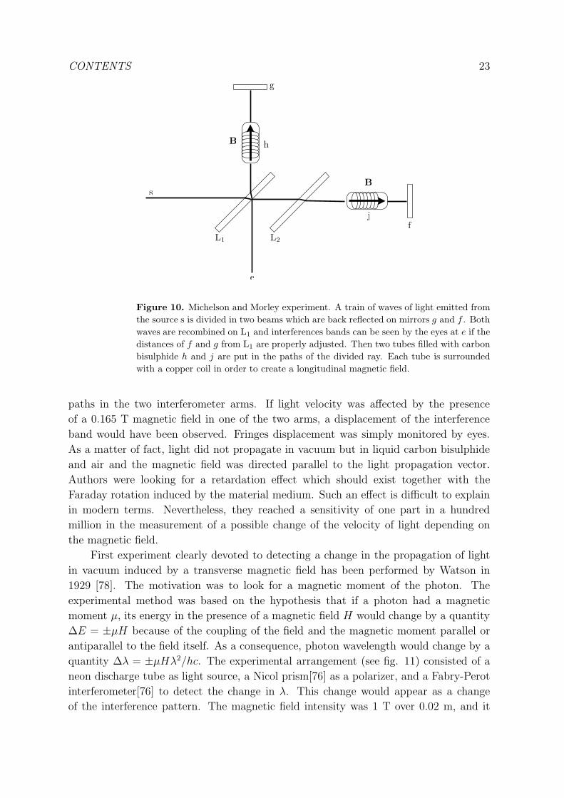
Figure 10. Michelson and Morley experiment. A train of waves of light emitted from
the source s is divided in two beams which are back reflected on mirrors g and f . Both
waves are recombined on L1 and interferences bands can be seen by the eyes at e if the
distances of f and g from L1 are properly adjusted. Then two tubes filled with carbon
bisulphide h and j are put in the paths of the divided ray. Each tube is surrounded
with a copper coil in order to create a longitudinal magnetic field.
paths in the two interferometer arms. If light velocity was affected by the presence
of a 0.165 T magnetic field in one of the two arms, a displacement of the interference
band would have been observed. Fringes displacement was simply monitored by eyes.
As a matter of fact, light did not propagate in vacuum but in liquid carbon bisulphide
and air and the magnetic field was directed parallel to the light propagation vector.
Authors were looking for a retardation effect which should exist together with the
Faraday rotation induced by the material medium. Such an effect is difficult to explain
in modern terms. Nevertheless, they reached a sensitivity of one part in a hundred
million in the measurement of a possible change of the velocity of light depending on
the magnetic field.
First experiment clearly devoted to detecting a change in the propagation of light
in vacuum induced by a transverse magnetic field has been performed by Watson in
1929 [78]. The motivation was to look for a magnetic moment of the photon. The
experimental method was based on the hypothesis that if a photon had a magnetic
moment µ, its energy in the presence of a magnetic field H would change by a quantity
∆E = ±µH because of the coupling of the field and the magnetic moment parallel or
antiparallel to the field itself. As a consequence, photon wavelength would change by a
quantity ∆λ = ±µHλ2/hc. The experimental arrangement (see fig. 11) consisted of a
neon discharge tube as light source, a Nicol prism[76] as a polarizer, and a Fabry-Perot
interferometer[76] to detect the change in λ. This change would appear as a change
of the interference pattern. The magnetic field intensity was 1 T over 0.02 m, and it

CONTENTS 24
was directed perpendicularly to the light direction of propagation. Interference pattern
with and without the magnetic field was captured by a photographic camera. The
region inside the 0.01 m long Fabry-Perot interferometer was evacuated. The author
stated that the alteration in the refractive index of vacuum produced by a magnetic
field perpendicular to the direction of light propagation does not exceed 4 × 10⁻⁷ per
Tesla. Nowadays, we know that because of the Cotton-Mouton effect of Vacuum the
expected variation of light velocity is quadratic in the magnetic field and is of the order
of 10−24.
Motivated again by the search for a photon magnetic moment and by Watson’s
paper [78], Farr and Banwell in 1932 [79] and 1940 [80] reported measurements of
the velocity of propagation of light in vacuum in a transverse magnetic field. Their
experiment was first based on a Jamin interferometer[76] and in the 1940 version on a
Michelson interferometer [76].
L SN C PI
B0
Figure 11. Watson’s experiment. Light coming from a neon discharge tube (N)
passes through a Nichols prism N and a transverse magnetic field produced by an
electromagnet. A Fabry Perot interferometer I is placed on the beam path and a lens
L image the fringes pattern on a photographic camera P through slits S and collimator
C.
Light from an incandescence lamp was polarized by a Nicol prism [76], separated
in two and then one of the rays passed through a magnetic field of 1.8 T over 1.125 m.
Observation of a possible fringe displacement induced by the magnetic field was first
observed by eyes. In the 1940 version of their apparatus the detector was a photoelectric
cell, the signal of which was amplified and read by a galvanometer to record it on a
moving photographic strip which increased the apparatus sensitivity. The final result
was that in a 2 T field the relative variation of light velocity was less than 2 × 10⁻⁹
[80].
No clear theoretical predictions were motivating such experiments. First citation of
the existence in a vacuum of the Cotton-Mouton effect can only be found in a paper by
Erber in 1961 [81] which also provides an estimation of the value of the Cotton-Mouton
∆nCM , and where a discussion of different experimental approaches can also be found.
This renewed interest was motivated by the laser invention [31] and the progresses in
magnets providing fields of several Tesla. This has raised the hope that effects due to
vacuum polarization in the presence of a strong magnetic field could be soon observable.
The idea of using a Michelson-Morley interferometer to measure the variation of
velocity of light induced by a magnetic field has been proposed again several times [82],
CONTENTS 25
[83], [84], [85] following the technical progresses in Michelson interferometry driven by
the search for gravitational waves on earth [86],[87] using such an apparatus.
The theoretical results published in the seventies [16], [67] raised a new interest
in the field and in 1979 Iacopini and Zavattini proposed to measure the vacuum linear
magnetic birefringence via the ellipticity induced on a linearly polarized laser beam by
the presence of a transverse magnetic field [88]. Actually, a linearly polarized light
beam propagating in a birefringent medium becomes elliptically polarized. In general,
the acquired ellipticity Ψ is related to a birefringence ∆n by the formula:
Ψ = πL
λ∆n sin 2θ, (57)
where L is the optical path in the birefringent medium, λ is the light wavelength
and θ the angle between the light polarization and the birefringence axis [76]. If L is
considerably greater than λ, the measurement of Ψ can become an interesting indirect
method to measure ∆n. The measurement of the ellipticity is the main method to study
Cotton-Mouton effect since its discovery in 1902 [89]. Since Ψ is proportional to ∆n, in
the case of vacuum Cotton-Mouton effect Ψ ∝(
B0
Bcr
)2.
It is worth mentioning that the propagation in a birefringent medium not only
induces an ellipticity, but it also rotates the light polarization direction [76]. If Ψ ≪ 1 the
rotation angle θr can be written as θr ≤ Ψ2
2, therefore one can assume that θr ∝ (∆n)2,
and in particular for vacuum Cotton-Mouton effect θr ∝(
B0
Bcr
)4. This means that this
rotation can be safely neglected.
Zavattini’s proposal has been a big step forward since all the experiments performed
in recent years or under way are based on it. Let’s discuss it in details.
In order to have a larger optical path in the field the effect to be measured
is increased using an optical cavity. Moreover the ellipticity and the magnetic field
were modulated in order to be able to use heterodyne detection technique to increase
the signal to noise ratio. As sketched in figure 12, a linearly polarized beam passes
through an ellipticity modulator composed by a Faraday cell and a quarter wave plate
properly aligned. The magnetic field of the faraday cell gives a modulated ellipticity
η(t) = η0 cos(Ωt), which induces an ellipticity modulation. Then the beam is injected in
a transverse magnetic field surrounded by an optical cavity defined by mirrors M1 and
M2. The magnetic field is also modulated so that the ellipticity induced by the field
can be written as ψ(t) = ψ0 cos(ωt + φ). At the output of the optical cavity, the light
beam is analyzed with a polarizer (A) crossed with respect to the first one (P ). The
light is sent to two photodiodes which deliver signals proportional to I‖ and I⊥. The
transmitted light after the optical cavity is :
I⊥ = I0[σ2 + (Θ + ψ(t) + η(t))2], (58)
where I0 is the beam intensity before the analyzer, σ2 is the extinction factor of the
polarizers, Θ represents any static uncompensated ellipticity.
Developing Eq. (58), one sees that the transmitted light is composed of different
frequency components (see table 2).

CONTENTS 26
Frequency Intensity/I0DC σ2 +Θ2 + η20/2 + Ψ2
0/2
2Ω0 η20Ω0 ± ω η0ψ0 signal to be measured
Ω0 2I0Θη0
Table 2. Fourier components of the transmitted light of interest for the heterodyne
detection technique.
Basically, one gives up the idea to measure directly the variation of light velocity
as using a Michelson interferometer and one restricts himself to the measurement of
∆nCM . The advantage is the expected noise reduction with respect to the Michelson
interferometer apparatus where interfering light follows two different paths.
M1 M2
magnetic field
region
FC QW︸︷︷︸
Ω(t)
ω(t)
I‖
I⊥
B0
Eω Eω
ellipticity
modulator
Figure 12. Zavattini’s proposal for ellipticity measurement. A linearly polarized
beam is injected in a Fabry-Perot cavity formed by the two mirrors M1 and M2, in
which a magnetic field ~B0 is applied. The induced birefringence (Cotton Mouton effect)
transforms the linear polarization in an elliptical polarization. The induced ellipticity
is enhanced by an optical cavity because the effect can be summed when light goes
back and forth in the magnetic field. The apparatus is put between crossed polarizer
and analyzer in order to measure the ellipticity given by the ration I⊥/I‖. Moreover
one can modulate the field and use an ellipticity modulator for measuring the effect
with an heterodyne detection.
After tests at CERN [90] in Switzerland [91], an apparatus has been set up at
the Brookhaven National Laboratory [92], USA [93]. It is based on a multipass cavity
for enhancing the signal by a factor 250, and a magnetic field up to 4 T over 8.8 m
modulated at about 30 mHz. In ref. [93], authors report a sensitivity in ellipticity of
7.9×10⁻⁸ rad/√Hz. This sensitivity being insufficient to detect the QED effect, authors
concentrated their effort on the search for the existence of particles beyond the standard
model coupling with electromagnetic fields.
Actually, in 1986, Maiani, Petronzio, and Zavattini [94] showed that hypothetical
low mass, neutral, spinless bosons, scalar or pseudoscalar, that couple with two
photons could induce an ellipticity signal in the Zavattini apparatus similar to the
one predicted by QED. Moreover, an apparent rotation of the polarization vector
of the light could be observed because of conversion of photons into real bosons

CONTENTS 27
resulting in a vacuum magnetic dichroism which is absent in the framework of standard
QED. The measurements of ellipticity and dichroism, including their signs, can in
principle completely characterize the hypothetical boson, its mass ma, the inverse
coupling constant Ma, and the pseudoscalar or scalar nature of the particle. Maiani,
Petronzio, Zavattini paper was essentially motivated by the search for axions. These are
pseudoscalar, neutral, spinless bosons introduced to solve what is called the strong CP
problem i.e. the fact that there is no experimentally known violation of the CP-symmetry
in quantum chromodynamics even if there is no known reason for it to be conserved in
QCD specifically. A discussion about non standard model physics in external fields can
be found in ref.[95].
No signal was observed and the final result of the Brookhaven National Laboratory
experiment was that kCM ≤ 2.2× 10⁻¹⁹ T−2.
In 1991, a new attempt to measure the vacuum magnetic birefringence has been
started at the LNL [96] in Legnaro, Italy, by the PVLAS collaboration [70]. This
experiment is again based on ref. [88]. A vertical Fabry-Perot cavity is used to increase
the effect to be measured, while a superconductive 5 T magnet rotates around its own
axis to modulate it. To the first order, this case can be calculated in the approximation
of regarding the magnetic field as fixed at its instantaneous angular orientation, using
the standard vacuum birefringence formulae for a static magnetic field [97]. Results on
vacuum magnetic birefringence published in 2008 [98] indicates that the apparatus had
a noise level of about 1.7× 10⁻²⁰ T−2 for kCM .
In the meantime a new proposal has been put forward based at National Tsing Hua
University [99], Hsinchu, Taiwan, Republic of China : the Q&A project. This project
started around 1996 [100]. The experimental set up is similar to the PVLAS one but
the magnetic field is produced by permanent magnets, the 3.5 m long cavity is formed
by two high reflectivity mirrors suspended with two X-pendulum suspensions mounted
on two isolated tables. No birefringence effect has been yet detected and the achieved
sensitivity in ellipticity is 10−6 rad/√Hz [101].
Another proposal based on the use of pulsed magnets as suggested in ref [102] has
been presented in ref. [103] : the BMV project. This experiment is also based on the
Zavattini proposal and it is mounted at the LNCMI-T [46], Toulouse, France. The Fabry
Perot cavity is 2.2 m long and the cavity finesse is greater than 400 000. The novelty of
this experiment is the use of pulsed magnets in order to reach higher fields. A specially
designed magnet delivers more than 10 T in a first version, and 30 T has been already
reached for the next generation experiment. In ref. [104] authors show that a single
magnetic pulse is sufficient to detect birefringence signals as low as kCM ≈ 5 × 10⁻²⁰
T−2.
The use of long superconducting magnets developed for accelerator machines has
been also proposed by a collaboration [105] based at Fermilab [106], USA, and more
recently by a group based at CERN [90] : OSQAR [107].
Finally very recently a new version of the PVLAS experiment has been set up at
the INFN [108] in Ferrara (Italy). As the Q&A experiment, it is based on the use of
CONTENTS 28
rotating permanent magnets. The value of the field is 2.3 T. A Fabry-Perot cavity with
a finesse of about 250 000 is used to increase the optical path. This apparatus has given
a limit on vacuum magnetic linear birefringence of kCM ≤ 4.4× 10⁻²¹ T−2 [109].
Ellipticity formula given before (Eq. (57)) shows that decreasing the light
wavelength increase the ellipticity effect to be measured. Erber discussed this
experimental possibility in his 1961 paper [81], and more recently in ref. [110] a proposal
to use gamma rays to measure the vacuum magnetic birefringence can be found. Gamma
rays are produced by inverse Compton scattering on an electron beam of a storage ring
by a polarized laser beam. In principle the photons obtained are also polarized. After
passing through a magnetic field, gamma polarization is analyzed by using the fact that
shower production depends on gamma polarization in crystals.
The basic idea hidden in the Watson’s apparatus of 1929 was to transform a light
velocity variation into a frequency variation. Frequency measurements are among the
most precise measurements that can be performed nowadays (see e.g. [111]). Resonance
frequency of optical cavities depends on the optical length of the cavity itself. Any
variation of the index of refraction, for example induced by a magnetic field, will induce
a variation of the resonance frequency. This gives the signal to be measured by beating it
with a frequency reference signal. For vacuum Cotton-Mouton effect this idea has been
first envisaged by Erber [81]. More recently, the use of a ring He-Ne laser, i.e. a laser
based on a ring optical cavity, is suggested in ref. [112], a linear Fabry-Perot cavity
in ref. [89], and a feasibility study of a vacuum magnetic birefringence by frequency
shift measurement can be found in ref. [113]. All methods give beat frequencies to be
measured of the order of 10 nHz corresponding to a relative frequency shift of about 10−22
which looks very challenging since nowadays the best relative frequency measurements
are at the level of about 10−17 (see e.g. [111]).
As far as Kerr effect is concerned, let’s recall that experiments in the presence of
a static electric field looks from the technological point of view more difficult since to
equalize the effect of a 1 T magnetic field one needs a 300 MV/m electric field. This is
certainly the reason why the experimental observation of the Kerr effect in vacuum has
never been tried yet.
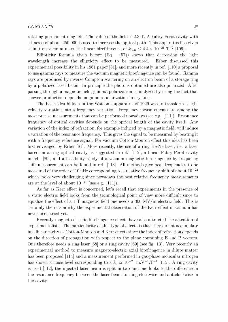
Recently magneto-electric birefringence effects have also attracted the attention of
experimentalists. The particularity of this type of effects is that they do not accumulate
in a linear cavity as Cotton-Mouton and Kerr effects since the index of refraction depends
on the direction of propagation with respect to the plane containing E and B vectors.
One therefore needs a ring laser [68] or a ring cavity [69] (see fig. 13). Very recently an
experimental method to measure magneto-electric axial birefringence in dilute matter
has been proposed [114] and a measurement performed in gas-phase molecular nitrogen
has shown a noise level corresponding to a ka ≃ 10−23 m.V−1.T−1 [115]. A ring cavity
is used [112], the injected laser beam is split in two and one looks to the difference in
the resonance frequency between the laser beam turning clockwise and anticlockwise in
the cavity.
CONTENTS 29
B0
E0
Figure 13. Magneto-electric measurement. A ring Fabry Perot cavity is injected
by two resonant beams. The induced magneto-electric birefringence depends on the
direction of the light propagation with respect to the orientation of the electric and
magnetic fields. Beams at the output of the interferometer are frequency shifted from
each other because of magneto-electric birefringence.
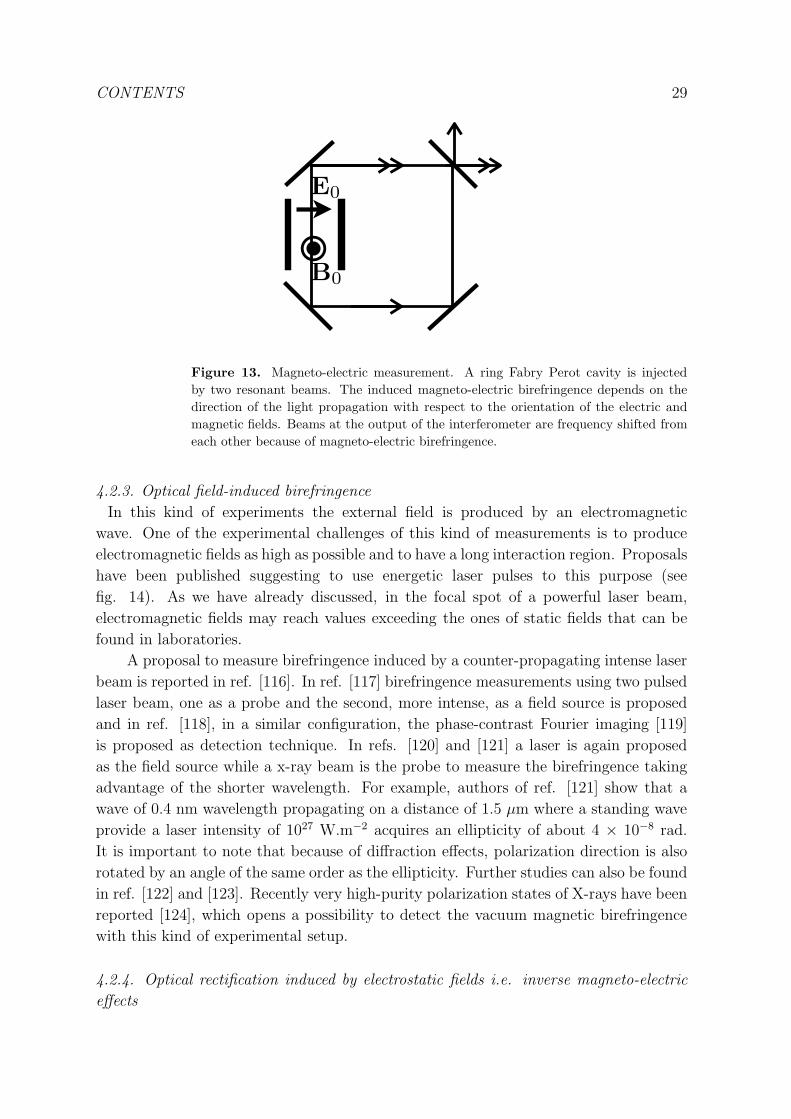
4.2.3. Optical field-induced birefringence
In this kind of experiments the external field is produced by an electromagnetic
wave. One of the experimental challenges of this kind of measurements is to produce
electromagnetic fields as high as possible and to have a long interaction region. Proposals
have been published suggesting to use energetic laser pulses to this purpose (see
fig. 14). As we have already discussed, in the focal spot of a powerful laser beam,
electromagnetic fields may reach values exceeding the ones of static fields that can be
found in laboratories.
A proposal to measure birefringence induced by a counter-propagating intense laser
beam is reported in ref. [116]. In ref. [117] birefringence measurements using two pulsed
laser beam, one as a probe and the second, more intense, as a field source is proposed
and in ref. [118], in a similar configuration, the phase-contrast Fourier imaging [119]
is proposed as detection technique. In refs. [120] and [121] a laser is again proposed
as the field source while a x-ray beam is the probe to measure the birefringence taking
advantage of the shorter wavelength. For example, authors of ref. [121] show that a
wave of 0.4 nm wavelength propagating on a distance of 1.5 µm where a standing wave
provide a laser intensity of 1027 W.m−2 acquires an ellipticity of about 4 × 10⁻⁸ rad.
It is important to note that because of diffraction effects, polarization direction is also
rotated by an angle of the same order as the ellipticity. Further studies can also be found
in ref. [122] and [123]. Recently very high-purity polarization states of X-rays have been
reported [124], which opens a possibility to detect the vacuum magnetic birefringence
with this kind of experimental setup.
4.2.4. Optical rectification induced by electrostatic fields i.e. inverse magneto-electric
effects

CONTENTS 30
Eω
Eω
Bω
Figure 14. Optical field-induced birefringence. The external electric or magnetic
field is produced by an electromagnetic wave. In this kind of experiment, a linearly
polarized beam becomes elliptically polarized passing through another electromagnetic
wave.
In a standard medium optical rectification can be induced by a light beam in the
presence of an external magnetic and/or electric field. These effects are also known as
inverse effects with respect to the field-induced birefringences.
MICM
Figure 15. Inverse magneto electric effects. Optical rectification induced by the
presence of an external magnetic or electric field. Here the interaction between two
photons of the electromagnetic wave and a photon of the static magnetic field gives
rise to a magnetization M. This effect is known as Inverse Cotton Mouton effect if the
static magnetic field is perpendicular with respect to the direction of light propagation.
For example, the Inverse Cotton-Mouton Effect (ICME) corresponds to a static
magnetization induced in a medium by a non resonant linearly polarized light beam
propagating in the presence of a transverse magnetic field (see fig. 15). This
magnetization is proportional to the value of the magnetic field, and to the intensity of
the propagating electromagnetic wave (see ref. [5] and refs. therein). As stated in ref.
[5], microscopically, the light-induced dc magnetization arises in a standard medium
because the optical field shifts the different magnetic states of the ground manifold
differently, and mixes into these ground states different amount of excited states. It
looks like that inverse effects have not attracted much the attention of experimentalists.

CONTENTS 31
The observation of the ICME has only been reported very recently in a Terbium Gallium
Garnet crystal [125]. The ICME has also been calculated for the quantum vacuum in
ref. [126].
Starting point of the calculation is eq. 32. Two cases are possible (Eω‖B0, Bω⊥B0)
or (Eω⊥B0, Bω‖B0).
In the first case one gets:
MICM‖ = 14c2,0ǫ0E2ω
B0
µ0= 14c2,0
Iωc
B0
µ0. (59)
In the second case one obtains:
MICM⊥ = 8c2,0B2
ω
µ0
B0
µ0
= 8c2,0Iωc
B0
µ0
. (60)
where Iω is the intensity associated to the electromagnetic wave, and where we have
used the relation c0,2 = 7c2,0. In both cases MICM is parallel to B0.
If a laser pulse is focused to get Iω ≈ 1026W.m−2 in a vacuum where a transverse
magnetic field of more than 10 T is present, the magnetization to be measured because
of the ICME of the quantum vacuum is
MICM‖ ≈ 8× 10⁻¹¹T (61)
and
MICM⊥ ≈ 4.5× 10⁻¹¹T (62)
where we have used the relation µ0M(A/m)= M(T). Authors of ref. [126] suggest
that these values could be reached with new laser facilities but the very small value
of the induced magnetization remains an experimental challenge (Optical field induced
magnetization as small as 10−10 T are reported in [127]).
Symmetry considerations already applied to direct effects indicate that inverse Kerr
effect and inverse magneto electric birefringence effects exist in vacuum as well.
4.2.5. Optical field induced inverse magneto-electric effects
As in the case of magneto-electric birefringences, inverse effects might also be induced
by fields associated to electromagnetic waves. As far as we know, this subject has never
been treated in literature.
4.2.6. Parametric amplification induced by an electrostatic field : photon splitting
Since the seventies ([16], [128]) physicists have studied a phenomenon called photon
splitting which is the splitting of a photon propagating in vacuum into two photons
in the presence of a transverse magnetic field (fig. 16). In terms of nonlinear optics
textbooks this phenomenon is a parametric amplification induced by an electromagnetic
field, but as far as we know it has not been observed in standard media. The incoming
photon beam can be considered as the pump electromagnetic wave, and the outcoming
photon beams as the signal electromagnetic wave and the idler electromagnetic wave

CONTENTS 32
B0
Figure 16. Parametric amplification induced by an electromagnetic field : splitting
of photon into two photons in the presence of a magnetic field.
[5]. Reference paper for vacuum effect is ref. [67]. The results of this work have been
confirmed more recently in ref. [129].
Calculations reported in ref. [67] are far from being straightforward and they cannot
be resumed here easily. We resume in the following the main results and we give some
numerical estimations of such an effect.
k k1
k2
Figure 17. Box diagram for photon splitting with pump, signal and idler waves all
collinear. The × denotes an interaction with the external field. The contribution of
this diagram vanishes in vacuum.
First of all, let’s consider the case of a constant and spatially uniform external
magnetic field, with pump, signal and idler waves all collinear. The contribution of the
box Feynman diagram corresponding to the interaction of three photons with external
field once (figure 17) vanishes, so the leading diagram which contributes to photon
splitting is the hexagonal one corresponding to three photons interacting with the
external field three times (figure 18). The pump field attenuation during propagation will
be proportional to B30 , while energy attenuation will be proportional to B6
0 . The splitting
phenomenon also depends on photon polarization with respect to the external field
component perpendicular to the wavevector. Kinematic selection rules and CP selection
rules allow only photons polarized parallel to the transverse external field to split, and
they can only split into two photons polarized perpendicular to the transverse external
field. In principle, photon splitting would polarize an incoming beam in the direction
perpendicular to the transverse external magnetic field. This can be summarized in the
following formula:
κ(‖)→(⊥)+(⊥) ≈(
13α3
9450π2
)(
hω
mec2
)5 (B0 sin θ
Bcr
)6 (mec
h
)
, (63)

CONTENTS 33
k2
k1k
Figure 18. Hexagon diagram for photon splitting. Each × denotes an interaction
with the external field.
where κ is the attenuation coefficient in m−1 and θ the angle between the external
magnetic field and the propagation wavevector.
This formula can be written as
κ(‖)→(⊥)+(⊥) ≈(
273α
8
)
(
hω
mec2
)5 (B2
cr
µ0
)(
B0 sin θ√µ0
)6 (mec
h
)
c23,0 (64)
and it can be further reduced to
κ(‖)→(⊥)+(⊥) ≈ 12.0
(
hω
mec2
)5 (B0 sin θ
Bcr
)6
. (65)
For photons of hω = 1.6 × 10⁻¹⁹ J (1 eV) under a 10 T transverse field, κ is as
small as 4.8 × 10−80 m−1.
Taking into account higher order diagrams does not change much this result since
their contributions are even smaller than the one from the hexagonal diagram as it
has been proved in ref. [67]. Taking into account radiative corrections should give a
correction of the order of α, a calculation which has not yet been performed.
If the outcoming photons are no more collinear to the incoming photon the box
diagram no longer vanishes (figure 19). This is the case when the magnetic field is no
more spatially uniform. This means that the magnetic field can transfer a momentum
p that one can write as hBcr
∂B∂l
where l is along the direction parallel to the incoming
wavevector. Following ref. [67], the ratio between the attenuation coefficient κbox due to
the box diagram over the attenuation coefficient κhexagon due to the hexagonal diagram
can be written as
κboxκhexagon
∼(
Bcr
B0sinθ
)4 (
−2cp
hω
)2
. (66)
If one has a 10 T transverse component and a 1000 T/m magnetic field gradient,
κbox contribution can be as 1010 times greater than the κhexagon contribution but the
resulting attenuation coefficient would anyway be of the order 10−70 m−1, which is
unmeasurable in a terrestrial laboratory. When B0 approaches Bcr, κhexagon becomes
more important than κbox.
A way to increase photon splitting probability is to use very high fields like the
one existing in atoms. The probability increases even more if the photon energy also
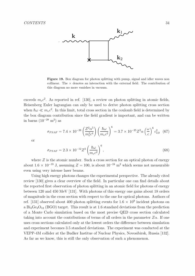
CONTENTS 34
k2
k1
k
Figure 19. Box diagram for photon splitting with pump, signal and idler waves non
collinear. The × denotes an interaction with the external field. The contribution of
this diagram no more vanishes in vacuum.
exceeds mec2. As reported in ref. [130], a review on photon splitting in atomic fields,
Heisenberg Euler lagrangian can only be used to derive photon splitting cross section
when hω ≪ mec2. In this limit, total cross section in the coulomb field is determined by
the box diagram contribution since the field gradient is important, and can be written
in barns (10−28 m2) as
σPSAF = 7.4× 10⁻²⁸
(
Z2α5
m2ec
4
)(
hω
mec2
)6
= 3.7× 10⁻²⁵Z2α(
ω
c
)6
c22,0 (67)
or
σPSAF = 2.3× 10⁻¹²Z2
(
hω
mec2
)6
, (68)
where Z is the atomic number. Such a cross section for an optical photon of energy
about 1.6 × 10⁻¹⁹ J, assuming Z = 100, is about 10−24 m2 which seems not measurable
even using very intense laser beams.
Using high energy photons changes the experimental perspective. The already cited
review [130] gives a clear overview of the field. In particular one can find details about
the reported first observation of photon splitting in an atomic field for photons of energy
between 120 and 450 MeV [131]. With photons of this energy one gains about 18 orders
of magnitude in the cross section with respect to the one for optical photons. Authors of
ref. [131] observed about 400 photon splitting events for 1.6 × 10⁹ incident photons on
a Bi4Ge3O12 (BGO) target. This result is at 1.6 standard deviations from the prediction
of a Monte Carlo simulation based on the most precise QED cross section calculated
taking into account the contributions of terms of all orders in the parameter Zα. If one
uses cross sections calculated only at the lowest orders the difference between simulation
and experiment becomes 3.5 standard deviations. The experiment was conducted at the
VEPP-4M collider at the Budker Institue of Nuclear Physics, Novosibirsk, Russia [132].
As far as we know, this is still the only observation of such a phenomenon.

CONTENTS 35
4.2.7. Optical field-induced photon splitting
As for the case of birefringences, one may study the case when photon splitting is
induced by an the electromagnetic field generated by an intense electromagnetic wave
(see fig. 20). Theoretical studies of such a phenomenon have been reported in ref. [133]
and more recently in ref. [134].
·B0
Figure 20. Optical induced photon splitting : photon splitting is induced by the
electromagnetic field generated by an intense electromagnetic wave.
Photon splitting probability depends essentially of two Lorentz-invariant
parameters [134], η = h2ωωL
m2ec
4 and χ = hωEω
mec2Ecr, where hω is the energy of the incoming
photon, hωL the energy of a photon of the electromagnetic wave generating the field and
Eω the electric field associated to this electromagnetic wave. The case corresponding to
η ≪ 1 and χ≪ 1 can be solved using the Heisenberg-Euler lagrangian. The conversion
rate obtained is WPSLA ∝ α3χ6 as shown in ref. [133] and [134].
Rates in more general cases are given in ref. [134]. Following conclusions of the
authors, it looks that even with fields Eω approaching Ecr as the ones provided by very
powerful future lasers, the conversion rate is such that an observation of optical field
induced photon splitting remains very difficult. For example, let’s assume that the field
is provided by a laser of intensity 1029 W.m−2 corresponding to Eω ∼ 5 × 10⁻³Ecr, and
that photon energy is 1.6 × 10⁻¹⁹ J, pulse duration 10 fs, pulse repetition rate 1 Hz.
Let’s imagine also to have incoming photons of energy between 120 and 450 MeV like in
ref.[131] for a total flux of 108 photons per second. Following ref. [134] this experimental
configuration would give an event rate smaller than 6 × 10⁻⁴ s−1. A rate that looks 106
times smaller than the one corresponding to the observation of photon splitting in the
atomic field [131].

CONTENTS 36
4.2.8. Second harmonic generation induced by an electromagnetic field : photon fusion
Second harmonic generation and parametric amplification are one the inverse effect of
the other. If one exists in vacuum the other exists as well. The same selection rules apply
to both of them. This means that the contribution of the box diagram to the probability
of conversion of two collinear incoming photons into one outcoming photon of twice the
energy of one incoming photon in the presence of a transverse magnetic field is zero
[135], [136]. At the lowest orders the transition probability is therefore proportional to(
B0
Bcr
)6and as for the photon splitting, photon fusion of collinear photons in a uniform
magnetic field looks unmeasurable in any terrestrial laboratory. As far as we know,
second harmonic generation induced by a magnetic field has never been observed even
in standard media, while second harmonic generation induced by an electric field has
been observed since the seventies [137].
The box diagram does not vanish if the incoming photons are not collinear and/or
the magnetic field is not uniform. These cases are treated in ref. [138] and more recently
in ref. [139]. In particular, the authors of this two papers treated the example of a pulsed
plane wave or a Gaussian laser beam propagating in uniform or non uniform dc fields.
Following ref. [139], an order of magnitude of the expected photon rate for a gaussian
beam in a uniform magnetic field can be obtained by the following formula
NSHG = 1.2× 10−36ρIλB20 , (69)
where the numerical factor is proportional to c22,0, ρ is the total time-averaged power
of fundamental harmonics, λ is the wavelength of fundamental harmonic, I is the laser
maximal intensity at focal point. Taking as values ρ = 105 W, I = 1026 W.m−2, λ = 0.8
× 10−6 m, as the authors of ref. [139], and B0 = 50 T one obtains NSHG ∼ 2.5 × 10⁻⁸
s−1 which seems very difficult to observe. For sake of argument let’s recall that best
single photon detectors in the near infrared region has dark count rates of the order of
10−3 s−1 (see e.g. [140]).
4.2.9. Optical field induced photon fusion
Photon fusion should also be induced using an electromagnetic wave as the field source
but no paper about it exists in literature, as far as we know. As for the case of photon
splitting one may guess that the optical field induced effect should not be easier to be
observed than the one induced via electrostatic fields.
4.2.10. Intensity dependent refractive index
As already discussed, the index of refraction for light propagating in the presence of
electromagnetic field depends on the field amplitude. This means that if the field is not
uniform but it depends on the spatial coordinates light will propagate in the presence
of a gradient of the index of refraction. It is also known that light ray generally bends
towards regions with a higher index of refraction. In this case the ray behavior can be
described solving what is called the eikonal equation [76]. For example, light passing in
a vacuum near a magnetic pole will bend toward the pole giving the impression to be

CONTENTS 37
attracted by the magnetic pole itself. A rough estimation of the deviation angle θd is
n(B0)/n(0) which for vacuum reduces to θd ∼ 7c2,0B2
0
µ0
≈ 9.3×10⁻²⁴B20 for light polarized
parallel to B0.
The magnetic deviation calculated using eikonal equation in the case of magnetic
dipole has been given in ref. [141], and [142]. It depends on the magnetic moment
orientation with respect to the light propagation direction, and it scales with the minimal
distance of the light ray to the magnetic moment ρm as 1/ρ6m. Our rough estimation
holds also for this more complicated case.
Actually an experiment has been performed around 1961 to look for such a deviation
and it has been reported in ref. [143]. The maximum field was of about 1 T and results
indicated that the magnetic deviation was less than 5 × 10⁻¹³ rad which is obviously
in agreement with our estimation of about 9 × 10⁻²⁴ rad.
It is clear that if one imagines a powerful laser beam, such that during propagation
energy density corresponds to fields approaching the critical ones, self focusing should
be observed because external rays will bend towards the inner region of the beam where
the index of refraction is higher. A discussion of this effect and other related to it can
be found in ref. [144]. From the experimental point of view the problem is that to get
fields of the order of the critical ones one needs lasers with a power of the order of 1033
W.m−2 and this will may be possible only in a far future since ongoing projects have
target intensity of 1030 W.m−2 [32].
The QED vacuum effects at the interfaces between region of different n, like the
creation of evanescent waves, has also been studied in ref. [145].
Let’s imagine now following ref. [121] proposal a x-ray probe beam traversing
a standing electromagnetic wave. In any point of the standing wave one can define
an electromagnetic field and therefore an index of refraction that depends on spatial
coordinates. In principle the standing wave acts on the probe beam as a diffraction
grating and a diffraction by a standing wave should be observed. The calculation of the
nonlinear phase shift acquired by crossing electromagnetic waves in a vacuum is also
reported [146]. A more recent proposal to observe light by light diffraction in vacuum
can be found in ref. [147]. A natural extention of such a kind of apparatus is to have
more than a standing wave to observe double-slit light by light interference as proposed
in ref. [148], and ref. [123] or strong periodic fields structured [149] to induce Bragg
scattering [150]. Authors of ref. [148] argue that for experimental parameters attainable
at upcoming XFEL and at ELI facilities (80 GW of x-rays in a 100 fs pulse of 0.4 nm
wavelength focused in a spot of 100 µm radius, and ELI expected power focused in a
diffraction limited spot), approximately 2 photons per laser shot can be diffracted so
that to give a measurable signal.
4.2.11. Photon-Photon scattering
Since the original paper of Euler and Kochel [12] it was clear that in the framework
of Quantum ElectroDynamics photon-photon scattering was allowed in vacuum. First
determination of the photon-photon scattering amplitude can be found in ref. [12].

CONTENTS 38
This result has been confirmed later using Feynman diagrams [151]. Very recently, a
tutorial paper showing how to compute low-energy photon-photon scattering has also
been published [152].
In the low energy approximation hω ≪ mec2 and for unpolarized light, the total
cross section can be written as
σγγ→γγ =973
10125πα2r2e
(
hω
mec2
)6
=973
20π
(
(hω)6
h4c4
)
c22,0 (70)
where the electron classical radius is re = αλ, and hω is the energy of a photon in
the reference frame of the center of mass [153].
This means that σγγ→γγ ≈ 7.3× 10−70 m2 when hω = 1.6 × 10⁻¹⁹ J.
The cross section increases very rapidly with photon energy, reaches a maximum
of 1.6× 10⁻³⁴ m2 when hω = 1.5 mec2 and then it decreases as (1/hω)2 [154] and [155].
As far as we know the first attempt to observe photon-photon scattering dates from
1928 [156] (see also ref. [157]), followed in 1930 by the experiment reported in ref. [158].
No scattered light was detected corresponding to an upper limit σγγ→γγ ≤ 3×10⁻²⁴ m2.
Notwithstanding proposals to use gamma rays [159] or X rays [160] to take advantage
of the higher cross section at these energies, no other experiment has been tried until
1996, when a new attempt to observe photon-photon scattering is reported in ref. [161].
This experiment was based on two laser beams provided by LULI [52], France, colliding
head-on in vacuum with a center of mass energy of 1.7 eV. The corresponding QED
cross section was 1.6 × 10−68 m2. No scattered photon was observed and authors gave
an upper limit of the cross section σγγ→γγ ≤ 9.9× 10−44 m2.
In ref. [162] photon scattering is studied in the case of three incoming beams
arranged so that the energy and momentum conservation conditions h(ω1 + ω2 − ω3) =
hω4 , k1+k2−k3 = k4 can be satisfied by a fourth, scattered beam. This configuration
stimulates the photon emission in the fourth beam and so the matching conditions fix
the direction of the generated wave (see fig 21).
ω4
in in
in
out
k1k2
k4
k3
ω3
ω1ω2
Figure 21. Photon photon scattering in four wave mixing configuration. The collision
of three beams satisfying the resonance condition in vacuum k1 + k2 = k3 + k4 and
ω1 + ω2 = ω3 + ω4, generate a fourth beam in the direction given by the matching
conditions. The generated beam is stimulated by the third beam. This configuration
avoids the detection of scattered incoming photons from the other beams.
This three beam geometry is also discussed in ref. [163]. Following these proposals,

CONTENTS 39
a new experiment has been mounted at LULI [52], France, and results reported in ref.
[164] in 2000.
The chosen geometry was the following : k1=kx, k2=ky, k3=k2z and k4=kx+
ky-k2z. Authors have chosen wavelength of 800 nm for beams 1 and 2, and 1300 nm for
the third one. The generated signal was expected in the visible at 577 nm. Thanks to
this geometry, both the wavelength and the direction of the generated wave is different
from the others, allowing to easily separate photons from QED scattering from photons
belonging to the incoming lasers. Energy of the two main beams at 800 nm was 0.4 J
with a duration of 40 fs (Full Width of Half Maximum), while the third one is generated
in an optical amplifier to shift its wavelength up to 1300 nm. The three beams are
injected in a vacuum chamber with a diameter of 3 cm. Authors have calibrated their
apparatus by measuring the third order susceptibility of nitrogen gas. In vacuum no
evidence for photon-photon scattering was observed and authors gave an upper limit
of the cross section σγγ→γγ ≤ 1.5 × 10−52 m2, at 18 orders of magnitude from QED
prediction.
In principle vacuum can be treated as a standard medium and, as shown in ref.
[165] a third-order nonlinear effective susceptibility χ(3)v can be defined
χ(3)v =
K
45πα
(
ree
mec2
)2
= 2ǫ0Kc2,0. (71)
K is a factor that depends on the directions of the incident beams and of their
polarization (K < 14) [165]. For K = 1, one gets χ(3)v ≈ 3.0× 10−41 m2.V−2.
In recent years several new proposals have been published but no new experiment
has been performed. While in ref. [166] the possibility to measure photon-photon
scattering using electromagnetic modes in a waveguide is discussed, the other proposals
[167], [168], [169], [170], [171], [172] are mostly motivated by the recent evolutions
in the field of very powerful laser sources which constitute a very important tool
for fundamental physics [173], [174]. In particular the perspectives of photon-photon
interaction experiments using high intensity laser are discussed in ref. [175].
The connection between the vacuum index of refraction n in the presence of an
external electromagnetic field and photon-photon scattering amplitude in the forward
direction f0 can be established thanks to the optical theorem [176]
n = 1 +2π
k2Nf0, (72)
where N is the average density of centers of scattering that is proportional to the
energy density of the external field and inversely proportional to the photon energy in
the center of mass reference frame.
Photon-photon cross section in the low energy limits depends on the lowest order
coefficients of the development of the Heisenberg-Euler lagrangian like c2,0. This is
true for any vacuum effect calculated in the same approximation and therefore any
experiment testing one of these effect and therefore measuring such coefficients also
indirectly test the existence of all the other effects. For example authors of ref. [177]

CONTENTS 40
argue that attempts to measure vacuum magnetic birefringence give better indirect
limits on σγγ→γγ than the one obtained by experiment reported in ref. [164].
4.3. Vacuum dichroism
In 1964 [178] was pointed out that the Heisenberg-Euler lagrangian has imaginary
contributions due to the poles in eq. 14. This means that together to a real part of the
index of refraction which gives rise to vacuum electromagnetic birefringences it exists
an imaginary part which corresponds to vacuum dichroism i.e. absorption of photons
in vacuum depending on photon polarization. This absorptive index of refraction arises
for the case of a pure external electric field. For the case of a pure magnetic field there
is no absorptive contribution to the index of refraction. If a static external electric field
E0 is present, one can write [178]
n⊥ ≃ 1 (73)
and
n‖ ≃ 1 +1
4iα
1
eπEcr
E0 − 1, (74)
where it is clear that only light polarized parallel to the external field can be
absorbed. Finally a linear absorption coefficient κ‖ can be defined
κ‖ = πα
λ
1
eπEcr
E0 − 1(75)
In principle, the behavior of the vacuum in a strong electric field is such that
an unpolarized light beam becomes partially polarized because the component of the
electric vibration parallel to the electric field is absorbed whereas the other component
is not. The electric field required to observe such a vacuum dichroism is of the order of
Ecr.
With the advent of very powerful laser sources, fields approaching the critical ones
can be achieved, and vacuum dichroism will eventually be observed by the associated
pair production by laser field [179] (see also [180] and refs. within).
4.4. Delbruck scattering
Electric fields as high as the critical one can be found at the surface of atomic nuclei.
To probe such a field light has to have wavelength of the order of the nucleus radius
which means high energy photons.
When high energy photons pass by a nucleus, they can not only be absorbed but
they can also be deflected by the Coulomb field. This phenomenon is known as the
Delbruck scattering since Delbruck first proposed it [181] to explain the results of
an experiment in which 2.615 MeV photons were scattered by lead and iron [182].
From a phenomenological point of view, in the low energy limit this effect can be
viewed as a consequence of the refractive index induced by the Coulomb field. As
CONTENTS 41
shown in ref. [183], in the high energy limit Delbruck scattering can be related to pair
production via the optical theorem. As discussed in reviews [184] and [185] comparison
between scattering experimental data and theoretical prediction of Delbruck scattering
are complex because the measured total scattering cross section depends also on the
contribution of the Rayleigh scattering and nuclear Compton scattering. The first clear
observation of Delbruck scattering was reported by Schumacher et al. [186] using 2.754
MeV photons on lead nuclei. The energy range around 2.7 MeV is somewhat ideal to
observe Delbruck scattering since at lower energy Rayleigh scattering dominates, while
at higher energy Compton scattering dominates. Experimental data cannot be explained
without taking into account the Delbruck scattering while to exactly reproduce their
value further corrections to the theoretical predictions, called Coulomb corrections, have
to be considered. The most recent measurements of high-energy Delbruck scattering
[187] have been performed at the Budger Institute of Nuclear Physics [132], Novosibirsk,
Russia.
5. Phenomenology in astrophysics
As we have discussed in all the previous paragraphs, vacuum non linearities need to be
detected an intense electromagnetic radiation source and strong electromagnetic fields.
This demand is a real challenge in terrestrial laboratories but there are places in the
cosmos where both radiation and fields exist. The celestial bodies that have attracted
most the attention of scientists to observe vacuum effects are strongly magnetized stars,
neutron stars [188] and white dwarfs [189]. Both kind of celestial objects are the
remnants of the implosion of massive stars: stars of a mass exceeding the solar one
in the case of neutron stars, and stars of masses about the solar one for white dwarfs.
Neutron stars have magnetic fields on their surface typically of about 107-108 T but
special neutron stars, called magnetars, are supposed to have surface magnetic fields
exceeding Bcr. White dwarf field typically ranges from 50 T to 104 T. The explanation
of such high fields is that during implosion the magnetic field flux is conserved. A star
like the sun has a field of about 5 × 10⁻³ T and a radius of about 7 × 10⁵ km, and after
implosion a neutron star as a radius of about 10 km and a white dwarf of about 104
km. The surface magnetic field is therefore much higher. Stars are obviously sources of
a large spectrum of radiation and the implications of QED in the observed emission of
such celestial objects is a very wide and important field that has been already treated
in specific reviews like in ref. [188] and more recently in ref. [190].
Magnetic ray bending in neutron stars has been studied in ref. [141], [142] and [191].
This phenomenon is related to the fact that the refractive index depends on the field
intensity. Like in the 1961 terrestrial experiment already cited [143], the idea consists in
observing the deflection of a light ray passing in a region where a non uniform magnetic
field is present. In ref. [142] a specific neutron star binary system is considered. Both
stars are pulsars which means that they emit a radiation beam along their magnetic
dipole direction. Periodically the beam of one of the two stars is eclipsed by the other

CONTENTS 42
one thus periodically the radiation beam of one of the two stars traverses a region where
a field of several Tesla exists over a distance of several hundreds of kilometers and it
should be bent in such a way to give to the signal observed on the earth a clear signature
of this QED magnetically induced lensing. This kind of lensing effect is similar to the
more studied gravitational one where light is bent by the gravitational field [192].
Magnetically induced spontaneous vacuum energy emission via the production of
real electron-positron pairs, which is also called vacuum breakdown, and its implication
for neutron star emission is the subject of ref. [193]. The basic idea is that it is possible
to release vacuum-energy from the vacuum by introducing an external magnetic field
because of the difference of vacuum energy with and without the field. In the case of
black holes [194], which are the remnants of the explosion of very massive stars, vacuum
breakdown in an external field has also been studied [195].
QED vacuum magnetization around neutron stars and its effect on neutron star
braking is studied in ref. [196] and [197]. This phenomenon, that the authors call
quantum vacuum friction, consists in the interaction between the star magnetic dipole
and the magnetic dipole induced in vacuum because of vacuum magnetization predicted
in the framework of QED. The star rotates around its own axis thus the vacuum dipole
also change in time. The two are not collinear because vacuum dipole, which is the sum
of the magnetization in all the points around the neutron star, is due to a retarded field
since the velocity of light is not infinite. The interaction between the two dipoles give
rise to a couple that tends to brake the star. This has important consequences on the
spindown evolution of neutron stars in particular in the case of magnetars.
The possibility to detect QED effects on the polarization of radiation emitted by
neutron star and white dwarfs is discussed in [198], [199], [200], [201], [202], [203], [204],
[205]. Combined effects of QED vacuum and plasma in the neighborhood of a neutron
star are studied in [206], [207], [208]. Photon-plasma interactions are also the object of a
review [175]. In general radiation emitted from the star propagates in a plasma but also
in the presence of high magnetic fields. Light polarization changes during propagation
so that star atmosphere emits polarized light even if the star surface radiation is not
polarized. The emission appears also to vary across the surface. The polarization across
the surface should also show special patterns because the rotating magnetic field twists
the polarization. All these subtle effects gives a clear signature to radiation observed on
the earth.
Nonlinear propagation of electromagnetic waves in the magnetosphere of a
magnetar, taking into account both the QED vacuum and the magnetized plasma,
has been also studied non-perturbatively in ref. [209]. The nonlinear behaviour of
these electromagnetic waves should play an important role in the energy transmission
in pulsars and magnetars.
Since the very beginning magnetized stars have been considered as the best choice
to observe photon splitting ([16], [128]). In a star magnetosphere only splitting of
a photon polarized parallel to the field into two photons polarized perpendicular to
the field is allowed because the index of refraction of the parallel propagation mode

CONTENTS 43
is greater than the perpendicular propagation mode. This is the only process that
conserves momentum. Again, magnetized stars like neutron stars should appear as
emitting polarized light. Moreover, photon splitting is more efficient for high energy
photons thus photon splitting has often been invoked to explain hard cutoffs in gamma-
ray spectra from pulsars [210], but data are difficult to interpret because one does not
know where gamma-rays are actually produced.
All this wide research domain has triggered the construction of a special satellite
GEMS [211] which goal is to measure the polarization of X rays sources. Its launch is
scheduled after November 2014, and neutron stars are between its prime targets.
6. Non trivial vacua
Examples of what is called non trivial vacua can be found in literature. This essentially
means that light propagates in a vacuum in which a distribution of real or virtual
photons exists. In this case one can calculate an average value for the E2 and B2 and
one can use this value to calculate the corresponding effects due in particular to four
wave mixing in vacuum. For example the velocity of light propagating perpendicular
to two parallel infinite conducting plates and in the region between them has been first
calculated by Scharnhorst [212]. The variation of the velocity of light is due to virtual
photons energy density which is also responsible of the well known Casimir effect [213].
The conceptual problem is that in the case treated by Scharnhorst the velocity of light
should exceed c. This has attracted a lot of interest (see e.g. ref. [214]), but as far as
we understand, this effect is also expected to be undetectable with up-to-date apparata.
The effect of real photon radiation associated to temperature with comparison to the
one associated to virtual photons is also discussed in ref. [215].
In the case of very intense photon beams, the photon density is so high that in
literature the term of radiation gas is used to indicate such an environment. QED
photon-photon interactions change the refractive index of a radiation gas and new optical
phenomena should appear. Selffocusing, the formation of so-called photon bullets [216],
[217], wave collapse [218], [219] and a phenomenon called photon acceleration in vacuum
[220].
7. CP violating vacuum
In the framework of the standard model, CP violation has been observed (see e.g. [221]).
In principle CP violation in photon-photon interactions would modify the quantum
vacuum behavior also in the case of light propagation. In particular terms corresponding
to coefficients c0,1 and c2,1 could exist in the lagrangian L. The phenomenology of the
existent of a term proportional to F 2G has been studied in ref. [222] and [223].
One of the main results is that a new type of Jones Birefringence depending on B20
should exist. Nevertheless the predicted effect in the framework of the standard model
is very small compared to the QED birefringence effects because the energy scale of such
CONTENTS 44
a new lagrangian term is the QCD one [223].
8. Conclusion
From the phenomenological point of view quantum vacuum can be treated as a standard
nonlinear optical medium. In the low photon energy limit and for fields smaller than the
critical ones the lowest order terms of the Heisenberg-Euler lagrangian are sufficient to
give precise predictions of the effects to be measured like in the case of vacuum Cotton-
Mouton magnetic birefringence. In principle, higher α contributions could be calculated
giving predictions more and more precise to compare with experimental results as in the
case of other important QED tests as for example the anomalous magnetic moment of
the electron (see e.g. ref. [224]). Our review is mainly devoted to this low energy, small
field limit. It is worth stressing that vacuum Cotton-Mouton magnetic birefringence
is the field where the only ongoing experiments exist. Experimentalists are at three
orders of magnitude from the QED predictions [109] and there is hope that in few years
one of the most fundamental predictions of Heisenberg-Euler lagrangian will be tested
experimentally.
At higher photon energies and/or at higher fields, theoretical calculations becomes
more difficult since they are no more perturbative in α. A large theoretical literature
exists covering a very wide spectrum of phenomena. Some of these works have been
triggered by the new intense lasers facilities under development. Actually, intense lasers
should give access to new and impressive QED effects (see e.g. the reviews [225] and
[226]) that have been treated in this review but that certainly deserve more space. Last
experiments on photon-photon scattering were at 18 orders of magnitude from the QED
prediction but a large number of proposals are just waiting for the new facilities to be
operational and eventually a complete new field will be opened.
For photons in MeV region, both Delbruck scattering [186] and recently photon
splitting in an atomic field [131] have been observed confirming once more that QED is
a very powerful tool to describe nature.
Last but not least, astrophysical tests of quantum vacuum properties seem very
promising and hopefully, thanks to more and more precise observational data, the cosmos
itself will become a laboratory to test QED photon-photon interactions.
9. Acknowledgements
We thank Mathilde Fouche and Geert Rikken for strong support and very useful
discussions. We also thank Mathilde Fouche for carefully reading the manuscript.

CONTENTS 45
[1] Aristotle, Physics, book IV, part VI-IX.
[2] J.D. Jackson, Classical electrodynamics, J. Wiley & Sons.
[3] M. Faraday, Phil. Mag. 28 (1846), 294 ; Phil. Trans. R. Soc. 136 (1846), 1.
[4] P.A. Franken, A.E. Hill, C.W. Peters, and G. Weinreich, Phys. Rev. Lett. 7 (1961), 118.
[5] Y.R. Shen, The Principles of Nonlinear Optics, (Oxford university press 2007) 6th ed..
[6] Landau-Lifschitz, Quantum Electrodynamics, Mir Edition.
[7] A.D. Buckingham, and J.A. Pople, Proc. Phys. Soc. 1369 (1956), 1133
[8] J.R. Oppenheimer and M.S. Plesset, Phys. Rev. 44 (1933), 53.
[9] P.A.M. Dirac, Rapport du 7e Conseil Solvay de Physique, Structure et Proprietes des Noyaux
Atomiques (1934), 203.
[10] O. Halpern, Phys. Rev. 44 (1933), 855.
[11] G. Breit and J.A. Wheeler, Phys. Rev. 46 (1934), 1087.
[12] H. Euler et B. Kochel, Naturwiss. 23 (1935), 246.
[13] H. Euler, Annalen der Physik 5 (1936), 398.
[14] W. Heisenberg and H. Euler, Z. Phys. 98 (1936), 714.
[15] V. Weisskopf, Mat.-Fis. Med. Dan. Vidensk. Selsk. 14 (1936), 6.
[16] Z. Bialynicka-Birula and I. Bialynicki-Birula, Phys. Rev. D 2 (1970), 2341.
[17] S. Schweber, QED and the men who made it, Princeton University Press.
[18] J.M. Jauch and K.M. Watson, Phys. Rev. 74 (1948), 950.
[19] R. Karplus and M. Neuman, Phys. Rev. 80 (1950), 380.
[20] J. Schwinger, Phys. Rev. 82 (1951), 664.
[21] J.S. Heyl, and L. Hernquist, Phys. Rev. D 55 (1997), 2449.
[22] G.V. Dunne, Int. J. Mod. Phys. 27 (2012), 1260004.
[23] V.I. Ritus, Soviet Physics-JETP 42 (1975), 774.
[24] R. Serber, Phys. Rev. 48 (1935), 49.
[25] E.A. Uehling, Phys. Rev. 48 (1935), 55.
[26] J.S. Heyl and L. Hernquist J. Phys. A: Math. Gen. 30 (1997), 6475.
[27] B. Huttner, and S.M. Barnett, Phys. Rev. A 46 (1992), 4306.
[28] T.G. Philbin, New Journal of Physics 12 (2010), 123008.
[29] P.K. Shukla, M. Marklund, D.D. Tskhakaya, and B. Eliasson, Phys. Plasmas 11 (2004), 3767.
[30] D. Kabat, K. Lee, and E. Weinberg, Phys. Rev. D 66 (2002), 014004.
[31] T. H. Maiman, Nature 187 (1960), 493.
[32] http://www.extreme-light-infrastructure.eu/
[33] http://www.ile.osaka-u.ac.jp/
[34] D. Strickland, and G. Mourou, Opt. Commun. 56 (1985), 219.
[35] V. Yanovsky, V. Chvykov, G. Kalinchencko, P. Rousseau, T. Planchon, T. Matsuoka, A.
Maksimchuk, J. Nees, G. Cheriaux, G. Mourou, and K. Krushelnick, Opt. Express 16 (2008),
2109.
[36] http://www.engin.umich.edu/research/cuos/ResearchGroups/HFS/Experimentalfacilities/
HERCULESPetawattLaser.html
[37] https://lasers.llnl.gov/
[38] http://www-lmj.cea.fr/
[39] http://public.web.cern.ch/public/en/lhc/howlhc-en.html
[40] http://www.magnet.fsu.edu/
[41] http://ghmfl.grenoble.cnrs.fr/
[42] http://www.ru.nl/hfml/
[43] http://english.hfcas.ac.cn/HMFL.htm
[44] http://www.nims.go.jp/TML/english/
[45] http://www.magnet.fsu.edu/about/losalamos.html
[46] http://www.toulouse.lncmi.cnrs.fr/
[47] http://www.hzdr.de/db/Cms?pNid=580

CONTENTS 46
[48] http://eng.whmfc.cn/category/10/2012-01-13/125449343.html
[49] http://www.toulouse.lncmi.cnrs.fr/spip.php?page=rubrique&id rubrique=36&lang=en
[50] P. Frings, J. Vanacken, C. Detlefs, F. Duc, J.E. Lorenzo, M. Nardone, J. Billette, A. Zitouni, W.
Bras, and G.L.J.A. Rikken, Rev. Sci. Instr. 77 (2006), 063903.
[51] M.S. Crosser, S. Scott, A. Clark, and P.M. Wilt, Rev. Sci. Instr. 81 (2010), 084701.
[52] http://www.luli.polytechnique.fr/
[53] M. Bass, P.A. Franken, J.F. Ward, and G. Weinreich, Phys. Rev. Lett. 9 (1962), 446.
[54] A. Yariv, and P. Yeh, Photonics, (John Wiley & Sons, New York 1984) 1st ed.
[55] J.A. Giordmaine and R.C. Miller, Phys. Rev. Lett. 14 (1965), 973.
[56] F. Pockels, Abhandl. Gesell. Wiss. Gottingen 39 (1893), 1 ; F. Pockels, Lehrbuch der Kristalloptik
(Teubner, Leipzig, 1906)
[57] D. Drung, C. Assmann, J. Beyer, A. Kirste, M. Peters, F. Ruede, and Th. Schurig, IEEE
Transactions on Applied Superconductivity 17 (2007), 699.
[58] T.D. Cohen, and E.S. Werbos, Phys. Rev. C 80 (2009), 015203.
[59] F. Karbstein, L. Roessler, B. Dobrich, and H. Gies, Int. J. Mod. Phys. Conf. Ser. 14 (2012), 403.
[60] J. Kerr, Br. Assoc. Rep. (1901), 568.
[61] A. Cotton and H. Mouton, Cr. r. hebd. Seanc Acad. Sci., Paris 141 (1905), 317 and 349 ; Ibid.
142 (1906), 203 ; Ibid. 145 (1907), 229 ; Ann. Chem. Phys. 11 (1907), 145 and 289.
[62] T. Roth and G.L.J.A. Rikken, Phys. Rev. Lett. 85 (2000), 4478.
[63] T. Roth and G.L.J.A. Rikken, Phys. Rev. Lett. 88 (2002), 063001.
[64] H.J. Ross, B.S. Sherbone, and G.E. Stedman, J. Phys. B: At. Mol. Opt. Phys. 22 (1989), 459.
[65] G.L.J.A. Rikken, C. Strohm and P. Wyder, Phys. Rev. Lett. 89 (2002), 133005.
[66] C. Rizzo and G.L.J.A. Rikken, Physica Scripta 71 (2005), C5.
[67] S. Adler, Ann. Phys. N.Y. 67 (1971), 599.
[68] V.I. Denisov, Phys. Rev. D 61 (2000), 036004.
[69] G.L.J.A. Rikken and C. Rizzo, Phys. Rev. A 63 (2000), 012107.
[70] D. Bakalov, F. Brandi, G. Cantatore, G. Carugno, S. Carusotto, F. Della Valle, A.M. De Riva,
U. Gastaldi, E. Iacopini, P. Micossi, E. Milotti, R. Onofrio, R. Pengo, F. Perrone, G. Petrucci,
E. Polacco, C. Rizzo, G. Ruoso, E. Zavattini, and G. Zavattini, Quantum Semiclass. Opt. 10
(1998), 239.
[71] P.J. Mohr and B.N. Taylor, Reviews of modern physics 77 (2005), 1.
[72] W. Tsai and T. Erber, Phys. Rev. D 12 (1975), 1132.
[73] J.S. Heyl and L. Hernquist, J. Phys. A: Math. Gen. 30 (1997), 6485.
[74] P. Castelo Ferreira and J. Dias de Deus, Eur. Phys. J. C 54 (2008), 539.
[75] G.L.J.A. Rikken, and C. Rizzo, Phys. Rev. A 67 (2003), 015801.
[76] Born & Wolf, Principles of optics, 6th ed., Pergamon Press.
[77] E.W. Morley, H.T. Eddy, and D.C. Miller, Bulletin Western Reserve University, 1 (1898), 50.
[78] W. H. Watson, Proc. Roy. Soc. London A 125 (1929), 345.
[79] C. C. Farr and C. J. Banwell, Proc. Roy. Soc. London A 137 (1932), 275.
[80] C. J. Banwell and C. C. Farr, Proc. Roy. Soc. London A 175 (1940), 1.
[81] T. Erber, Nature 190 (1961), 25.
[82] A.M. Grassi Strini, G. Strini and G. Tagliaferri, Phys. Rev. D 19 (1979), 2330.
[83] W-T. Ni, K. Tsubono, N. Mio, K. Narihara, S-C. Chen, S-K. King and S-S. Pan, Mod. Phys. Lett.
A 6 (1991), 3671.
[84] G. Zavattini, and E. Calloni, Eur. Phys. J. C 62 (2009), 459.
[85] B. Dobrich and H. Gies, EPL 87 (2009), 21002.
[86] see : http://www.ligo.caltech.edu/
[87] see : https://wwwcascina.virgo.infn.it/
[88] E. Iacopini and E. Zavattini, Phys. Lett. B 85 (1979), 151.
[89] C. Rizzo, A. Rizzo and D.M. Bishop, Int. Rev. Phys. Chem. 16 (1997), 81
[90] http://public.web.cern.ch/public/
CONTENTS 47
[91] E. Iacopini, B. Smith, G. Stefanini and E. Zavattini, Il Nuovo Cimento B 61 (1981), 21.
[92] http://www.bnl.gov/world/
[93] R. Cameron, G. Cantatore, A.C. Melissinos, G. Ruoso, Y. Semertzidis, H.J. Halama, D.M. Lazarus,
A.G. Prodell, F. Nezrick, C. Rizzo and E. Zavattini, Phys. Rev. D 47 (1993), 3707.
[94] L. Maiani, R. Petronzio, and E. Zavattini, Phys. Lett. B 175 (1986), 359.
[95] H. Gies, J. Phys. A: Math. Theor. 41 (2008), 164039.
[96] http://www.lnl.infn.it/
[97] S.L. Adler, J. Phys. A: Math. Theor. 40 (2007), F143.
[98] E. Zavattini, G. Zavattini, G. Ruoso, G. Raiteri, E. Polacco, E. Milotti, V. Lozza, M. Karuza,
U. Gastaldi, G. Di Domenico, F. Della Valle, R. Cimino, S. Carusotto, G. Cantatore, and M.
Bregant, Phys. Rev. D 77 (2008), 032006.
[99] http://www.nthu.edu.tw/english/index.php
[100] W-T Ni, Chin. J. Phys. 34 (1996), 962.
[101] H-H. Mei, W-T. Ni, S-J Chen, and S-S Pan, Mod. Phys. Lett. A 25 (2010), 983.
[102] C. Rizzo, EPL 41 (1998), 483
[103] R. Battesti, B. Pinto Da Souza, S. Batut, C. Robilliard, G. Bailly, C. Michel, M. Nardone, L.
Pinard, O. Portugall, G. Trenec, J-M. Mackowski, G.L.J.A. Rikken, J. Vigue, and C. Rizzo,
Eur. Phys. J. D 46 (2008), 323.
[104] P. Berceau, M. Fouche, R. Battesti, and C. Rizzo, Phys. Rev. A 85 (2012), 013837
[105] S.A. Lee, W.M. Fairbank Jr., W.H. Toki, J.L. Hall, T.S. Jaffery, P. Colestock, V. Cupps, H.
Kautzky, M. Kuchnir, and F. Nezrick, Fermilab proposal 877 (March 28 1995).
[106] http://www.fnal.gov/
[107] P. Pugnat, M. Kral, A. Siemko, L. Duvillaret, M. Finger, M. Finger, K.A. Meissner, D. Romanini,
M. Sulc, and J. Zicha, Czec J. Phys. 56 (2006), C193.
[108] http://www.fe.infn.it/
[109] G. Zavattini, U. Gastaldi, R. Pengo, G. Ruoso, F. Della Valle, and E. Milotti, Int. J. of Mod.
Phys. A 27 (2012), 1260017.
[110] G. Cantatore, F. Della Valle, E. Milotti, L. Dabrowski and C. Rizzo, Phys. Lett. B 265 (1991),
418.
[111] Q.-F. Chen, A. Nevsky, and S. Schiller, Appl. Phys. B 107 (2012), 679.
[112] G.E. Stedman, Rep. Prog. Phys. 60 (1997), 615.
[113] J.L. Hall, J. Ye, and L.S. Ma, Phys. Rev. A 62 (2000), 013815
[114] G. Bailly, R. Thon, and C. Robilliard, Rev. Sci. Instrumen. 81(2010), 033105.
[115] B. Pelle, H. Bitard, G. Bailly, and C. Robilliard, Phys. Rev. Lett. 106 (2011), 193003.
[116] E.B. Aleksandrov, A.A. Ansel’m and A.N. Moskalev, Soviet Physics-JETP 62 (1985), 680.
[117] A.N. Luiten and J.C. Peterson, Phys. Rev. A 70 (2004), 033801.
[118] K. Homma, D. Habs, and T. Tajima, Appl. Phys. B 104 (2011), 769.
[119] M. Bass ed., . Handbook of Optics, McGraw-Hill, 1995.
[120] T. Heinzl, B. Liesfeld, K-U Amthor, H. Schwoerer, R. Sauerbrey, and A. Wipf, Opt. Com. 267
(2006), 318.
[121] A. Di Piazza, K.Z. Hatsagortsyan, and C.H. Keitel, Phys. Rev. Lett. 97 (2006), 083603.
[122] M. Marklund, Nature Photon. 4 (2010), 72.
[123] B. King, A. Di Piazza, and C.H. Keitel, Nature Photon. 4 (2010), 92.
[124] B. Marx, I. Uschmann, S. Hofer, R. Lotzsch, O. Wehrhan, E. Forster, M. Kaluza, T. Stohlker,
H. Gies , C. Detlefs, T. Roth, J. Hartwig, and G.G. Paulus, Optics Com. 284 (2011), 915.
[125] A. Ben-Amar Baranga, R. Battesti, M. Fouche, C. Rizzo, and G.L.J.A. Rikken, EPL 94 (2011),
44005
[126] C. Rizzo, A. Dupays, R. Battesti, M. Fouche, and G.L.J.A. Rikken, EPL 90 (2010), 64003.
[127] N.G. Kalugin and G. Wagniere, J. Opt. B: Quantum Semiclass. Opt. 3 (2001), S189.
[128] S.L. Adler, J.N. Bachall, G.C. Callan, and M.N. Rosenbluth, Phys. Rev. Lett. 25 (1970), 1061.
[129] S.L. Adler and C. Schubert, Phys. Rev. Lett. 77 (1996), 1695.
CONTENTS 48
[130] R.N. Lee, A.L. Maslennikov, A.I. Milstein, V.M. Strakhovenko, and Yu.A. Tikhonov, Phys. Rep.
373 (2003), 213.
[131] Sh.Zh. Akhmadaliev, G.Ya. Kezerashvili, S.G. Klimenko, R.N. Lee, V.M. Malyshev, A.L.
Maslennikov, A.M. Milov, A.I. Milstein, N.Yu. Muchnoi, A.I. Naumenkov, V.S. Panin, S.V.
Peleganchuk, G.E. Pospelov, I.Ya. Protopopov, L.V. Romanov, A.G. Shamov, D.N. Shatilov,
E.A. Simonov, V.M. Strakhovenko, and Yu.A. Tikhonov, Phys. Rev. Lett. 89 (2002), 061802.
[132] http://www.inp.nsk.su/index.en.shtml/
[133] I. Affleck and L. Kruglyak, Phys. Rev. Lett. 59 (1987), 1065.
[134] A. Di Piazza, A.I. Milstein, and C.H. Keitel, Phys. Rev. A 76 (2007), 032103.
[135] M.G. Raizen and B. Rosenstein, Phys. Rev. Lett. 65 (1990), 2744.
[136] G.W. Ford and D.G. Steel, Phys. Rev. Lett. 65 (1990), 2745.
[137] C.G. Bethea, Appl. Opt. 14 (1975), 2435.
[138] Y.J. Ding and A.E. Kaplan, Int. J. Nonlin. Opt. Phys. 1 (1991), 51.
[139] A.E. Kaplan and Y.J. Ding, Phys. Rev. A 62 (2000), 043805.
[140] A.J. Miller, S. Woo Nam, J.M. Martinis, and A.V. Sergienko, Appl Phys. Lett. 83 (2003), 791.
[141] V.I. Denisov, I.P. Denisova, and S.I. Svertilov, Doklady Phys. 46 (2001), 705.
[142] A. Dupays, C. Robilliard, C. Rizzo, and G.F. Bignami, Phys. Rev. Lett. 94 (2005), 161101.
[143] R.V. Jones, Nature 186 (1960), 706 ; R.V. Jones, Proc. Roy. Soc. London A 260 (1961), 47.
[144] M. Soljacic and M. Segev, Phys. Rev. A 62 (2000), 043817.
[145] W. Li, J. Chen, G. Nouet, L-y. Chen, and X. Jiang, Appl. Phys. Lett 99 (2011), 051112.
[146] A. Ferrando, H. Michinel, M. Seco, and D. Tommasini, Phys. Rev. Lett. 99 (2007), 150404.
[147] D. Tommasini, and H. Michinel, Phys. Rev. A 82 (2010), 011803(R).
[148] B. King, A. Di Piazza, and C.H. Keitel, Phys. Rev. A 82 (2010), 032114.
[149] G.Y, Kryuchkyan and K.Z. Hatsagortsyan, Phys. Rev. Lett. 107 (2011), 053604.
[150] L.D. Landau and E.M. Lifshitz, Electrodynamics of Continuous Media, Pergamon Press, 1984.
[151] R. Karplus and M. Neuman, Phys. Rev. 83 (1951), 776.
[152] Y. Liang, and A. Czarnecki, Can. J. Phys. 90 (2012), 11.
[153] The photon center of mass frame (also called photon center of momentum frame) is the inertial
frame where the photon total energy is the smallest one.
[154] B. De Tollis, Nuovo Cimento 32 (1964), 757 ; Nuovo Cimento 32 (1965), 1182.
[155] D.A. Dicus, C. Kao and W.W. Repko, Phys. Rev. D 57 (1998), 2443.
[156] S. Vavilov, Jour. Russ. Phys. Chem. 60 (1928), 555.
[157] S. Vavilov, Phys. Rev. 36 (1930), 1590.
[158] A.L. Hughes and G.E.M. Jauncey, Phys. Rev. 36 (1930), 773.
[159] V.M. Harutyunian, F.R. Harutyunian, K.A. Ispirian and V.A. Tumanian, Phys. Lett. 6 (1963),
175; V.M. Harutyunian, F.R. Harutyunian, K.A. Ispirian and V.A. Tumanian, Soviet Physics-
JETP 18 (1964), 873.
[160] G. Rosen and F.C. Whitmore, Phys. Rev. 137 (1965), 1357.
[161] F. Moulin, D. Bernard, and F. Amiranoff, Z. Phys. C 72 (1996), 607.
[162] R.L. Dewar, Phys. Rev. A 10 (1974), 2107.
[163] G. Grynberg and J-Y. Courtois, C. R. Acad. Sci. Paris 311 (1990), 1149.
[164] D. Bernard, F. Moulin, F. Amiranoff, A. Braun, J.P. Chambaret, G. Darpentigny, G. Grillon, S.
Ranc, and F. Perrone, Eur. Phys. J. D 10 (2000), 141.
[165] F. Moulin, and D. Bernard, Opt. Com. 164 (1999), 137.
[166] G. Brodin, M. Marklund, and L. Stenflo, Phys. Rev. Lett. 87 (2001), 171801.
[167] J. Lundin, M. Marklund, E. Lundstrom, G. Brodin, J. Collier, R. Bingham, J.T. Mendoca, P.
Norreys, Phys. Rev. A 74 (2006), 043821.
[168] E. Lundstrom, G. Brodin, J. Lundin, M. Marklund, R. Bingham, J. Collier, J.T. Mendoca, P.
Norreys, Phys. Rev. Lett. 96 (2006), 083602.
[169] A.M. Fedotov, and N.B. Narozhny, Phys. Lett. A 362 (2007), 1.
[170] D. Tommasini, A. Ferrando, H. Michinel, and M. Seco, Phys. Rev. A 77 (2008), 042101.

CONTENTS 49
[171] D. Tommasini, A. Ferrando, H. Michinel, and M. Seco, Journal of high energy physics 11 (2009),
43.
[172] D. Tommasini, and H. Michinel, Phys. Rev. A 82 (2010), 011803(R).
[173] M. Marklund and J. Lundin, Eur. Phys. J. D 55 (2009), 319.
[174] T. Heinzl and A. Ilderton, Eur. Phys. J. D 55 (2009), 359.
[175] M. Marklund and P.K. Shukla, Rev. Mod. Phys. 78 (2006), 591.
[176] J. Haıssinski, S. Dagoret, M. Urban, and F. Zomer, Physica Scripta 74 (2006), 678.
[177] M. Bregant, G. Cantatore, S. Carusotto, R. Cimino, F. Della Valle, G. Di Domenico, U. gastaldi,
M. Karuza, V. Lozza, E. Milotti, E. Polacco, G. Raiteri, G. Ruoso, E. Zavattini, and G. Zavattini,
Phys. Rev. D 78 (2008), 032006.
[178] J.J. Klein and B.P. Nigam, Phys. Rev. 136 (1964), B1540.
[179] G.V. Dunne, H. Gies, and R. Schutzhold, Phys. Rev. D 80 (2009), 111301(R).
[180] L. Labun and J. Rafelski, Phys. Rev. D 84 (2011), 033003.
[181] M. Delbruck, Z. Physik 84 (1933), 144.
[182] L. Meitner, H. Koster, Z. Physik 84 (1933), 137.
[183] F. Rohrlich and R.L. Gluckstern, Phys. Rev. 86 (1952), 1.
[184] A.I. Milstein, and M. Schumacher, Phys. Reports 243 (1994), 183.
[185] M. Schumacher, Rad. Phys. Chem. 56 (1999), 101.
[186] M. Schumacher, I. Borchert, F. Smend, and P. Rullhusen, Phys. Letters B 59 (1975), 134.
[187] S.Z. Akhmadaliev, et al., Phys. Rev. C 58 (1998), 2844.
[188] A.K. Harding and D. Lai, Rep. Prog. Phys. 69 (2006), 2631.
[189] D. Koester, The Astron. Astrophys. Rev. 11 (2002), 33.
[190] J.S. Heyl, Proc. QED2012, (2012) 04002, open access at http://www.iesc-proceedings.org/.
[191] H.J.M. Cuesta, J.M. Salim, and J.A.D. Pacheco, Int. J. Mod. Phys. A 21 (2006), 43.
[192] M. Bartelmann and P. Schneider, Phys. Rep. 340 (2001), 291.
[193] S-S. Xue, Phys. Rev. D 68 (2003), 013004.
[194] P.C.W. Davies, Rep. Prog. Phys. 41 (1978), 1313.
[195] A. Treves and R. Turolla, ApJ 517 (1999) 396.
[196] A. Dupays, C. Rizzo, D. Bakalov and G.F. Bignami, EPL 82 (2008), 69002.
[197] A. Dupays, C. Rizzo, and G.F. Bignami, EPL 98 (2012), 49001.
[198] J.S. Heyl, and N.J. Shaviv, Phys. Rev. D 66 (2002), 023002.
[199] D. Lai and W.C.G. Ho, Phys. Rev. Lett. 91 (2003), 071101.
[200] A.Y. Potekhin, D. Lai, G. Chabrier, and W.C.G. Ho, ApJ. 612 (2004), 1034.
[201] M.H. van Kerkwijk, D.L. Kaplan, M. Durant, S.R. Kulkarni, and F. Paerels, ApJ. 608 (2004),
432.
[202] R.M. Shannon and J.S. Heyl, Mon. Not. R. Astron. Soc. 368 (2006), 1377.
[203] Yu.N. Gnedin, N.V. Borisov, V.M. larionov, T.M. Natsvlishvili, M.Yu. Piotrovich, and A.A.
Arkharov, Astron. Rep. 50 (2006), 553.
[204] M. van Adelsberg and D. Lai, AIP Conf. Proc. 968 (2008), 137.
[205] C. Wang and D. Lai, Mon. Not. R. Astron. Soc. 398 (2009), 515.
[206] J.H. Heyl, and L. Hernquist, Phys. Rev. D 59 (1999), 45005.
[207] A. Di Piazza, K.Z. Hatsagortsyan, and C.H. Keitel, Phys. Plas. 14 (2007), 032101.
[208] G. Brodin, M. Marklund, B. Eliasson, and P.K. Shukla, Phys. Rev. Lett. 98 (2007), 125001.
[209] D. Mazur and J.S. Heyl, Mon. Not. R. Astron. Soc. 412 (2011), 1381.
[210] M.G. Baring and A.K. Harding, ApJ 547 (2001), 929.
[211] http://heasarc.gsfc.nasa.gov/docs/gems/
[212] K. Scharnhorst, Phys. Lett. B 236 (1990), 354.
[213] H.B.G. Casimir, Proc. Kon. Nederland. Akad. Wetensch. B51 (1948), 793.
[214] P.W. Milonni and K. Svozil, Phys. Lett. B 248 (1990), 437.
[215] W. Dittrich and H. Gies, Phys. Rev. D 58 (1998), 025004.
[216] G. Brodin, L. Stenflo, D. Anderson, M. Lisak, M. Marklund, and P. Johannisson, Phys. Lett. A

CONTENTS 50
306 (2003), 206.
[217] M. Marklund, B. Eliasson, and P.K. Shukla, JETP Lett. 79 (2004), 262.
[218] P.K. Shukla and B. Eliasson, Phys. Rev. Lett. 92 (2004), 073601.
[219] M. Marklund, P.K. Shukla, and B. Eliasson, EPL 70 (2005), 327.
[220] J.T. Mendonca, M. Marklund, P.K. Shukla, and G. Brodin, Phys. Lett. A 359 (2006), 700.
[221] B. Aubert, et al. (The BABAR Collaboration), Phys. Rev. Lett. 101 (2008), 021801.
[222] B. Pinto Da Souza, R. Battesti, C. Robilliard, and C. Rizzo, Eur. Phys. J. D 40 (2006), 445.
[223] R. Millo and P. Faccioli, Phys. Rev. D 79 (2009), 65020.
[224] G. Gabrielse, D. Hanneke, T. Kinoshita, M. Nio, and B. Odom, Phys. Rev. Lett. 97 (2006),
030802 ; Phys. Rev. Lett. 99 (2007), 039902.
[225] T. Heinzl, Int. J. Mod. Phys. A 27 (2012), 1260010.
[226] A. Di Piazza, C. Muller, K.Z. Hatsagortsyan and C.H. Keitel, Rev. Mod. Phys. 84 (2012), 1177.