
Maglev and Linear Motors - askmar General Atomics Maglev.pdf · 6 Comparison of Maglev and Linear...
44
1 Presentation to SCAG Maglev Task Force 8 February 2007 For more information contact: Mike Simon, Director, Commercial Business Development ([email protected] , 858-676-7121) Maglev and Linear Motors for Southern California Transportation
Transcript of Maglev and Linear Motors - askmar General Atomics Maglev.pdf · 6 Comparison of Maglev and Linear...
1
Presentation to SCAG Maglev Task Force
8 February 2007For more information contact:
Mike Simon, Director, Commercial Business Development
([email protected], 858-676-7121)
Maglev and Linear Motorsfor Southern California Transportation
2
• Background: Application of Electromagnetic Technology to Transportation
• Transportation Systems Using GA Passive Maglev Technology
• Linear Induction Motor Rail (“LIM-Rail™”) Systems
•Conclusions
Presentation Topics
3
Background: Application of
Electromagnetic Technology to
Transportation
4
Critical Transportation Issues Facing CA
• Environmental impact, especially emissions of NOxand diesel particulate matter
• Other social and economic impacts
� Traffic congestion
� Noise
� Road damage
• Factors relating to the efficiency of goods movement
� Velocity – speed of moving cargo thru distribution system
� Throughput – volume of cargo moving thru distribution system
� Reliability – consistent, predictable timing of cargo movement
� Congestion – delays in goods movement thru system
5
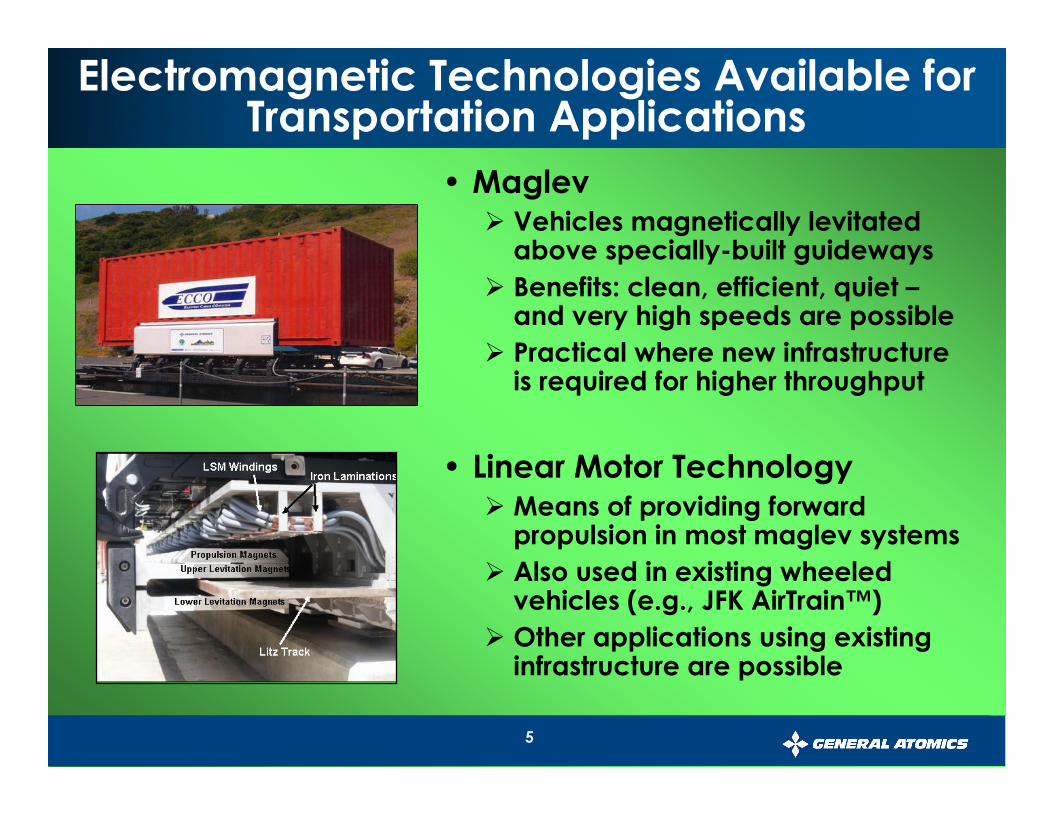
Electromagnetic Technologies Available for Transportation Applications
• Maglev� Vehicles magnetically levitated
above specially-built guideways
� Benefits: clean, efficient, quiet –and very high speeds are possible
� Practical where new infrastructure is required for higher throughput
• Linear Motor Technology� Means of providing forward
propulsion in most maglev systems
� Also used in existing wheeled vehicles (e.g., JFK AirTrain™)
� Other applications using existing infrastructure are possible
6
Comparison of Maglev and Linear Motor Technology Approaches
• Maglev
� Zero emissions at point of operation
� Operating on new, dedicated, above-grade guideways, can dramatically improve velocity and throughput
� Greatest potential to reduce noise and congestion
� Economically competitive where new infrastructure is required to meet goods movement demands
• Linear Induction Motor Rail (“LIM-Rail”) systems
� Also a zero emission solution
� Compatible with existing rail infrastructure
� Limited ability to address velocity and throughput, but can potentially achieve near term emissions benefits and set the stage for longer term infrastructure expansion using maglev

7
General Atomics & Affiliates
Defense
•UAV Systems
•Advanced Sensors
•Naval Ship Electrification
•Weapons Destruction
•EMALS
•AAG
Energy
•Fusion
•Uranium Mining &Conversion
•Reactor Development
Transportation
•Maglev Systems
•Streetcar Refurbishment
•Mining Truck Drives
•Track Refurbishment
Founded: 1955Employees: 4200 WorldwideMajor Businesses:
8
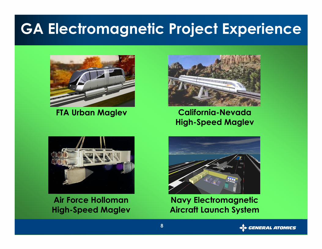
Air Force Holloman High-Speed Maglev
FTA Urban Maglev California-Nevada High-Speed Maglev
GA Electromagnetic Project Experience
Navy Electromagnetic Aircraft Launch System
9
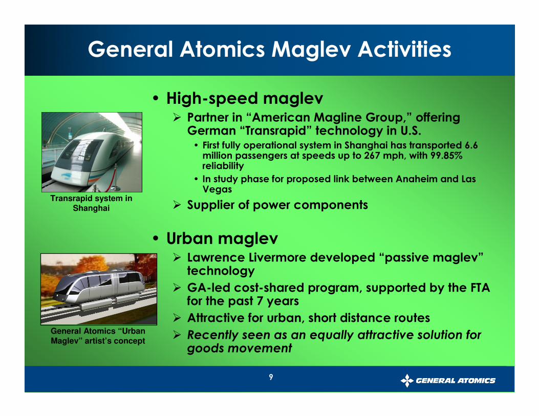
General Atomics Maglev Activities
• High-speed maglev� Partner in “American Magline Group,” offering
German “Transrapid” technology in U.S.• First fully operational system in Shanghai has transported 6.6
million passengers at speeds up to 267 mph, with 99.85% reliability
• In study phase for proposed link between Anaheim and Las Vegas
� Supplier of power components
• Urban maglev� Lawrence Livermore developed “passive maglev”
technology
� GA-led cost-shared program, supported by the FTA for the past 7 years
� Attractive for urban, short distance routes
� Recently seen as an equally attractive solution for goods movement
Transrapid system in Shanghai
General Atomics “Urban Maglev” artist’s concept
10
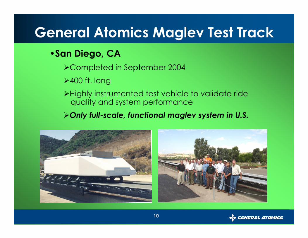
General Atomics Maglev Test Track
•San Diego, CA
�Completed in September 2004
�400 ft. long
�Highly instrumented test vehicle to validate ride quality and system performance
�Only full-scale, functional maglev system in U.S.
11
System ControlsEnergy Storage
Power ConvertersLaunch Motor
Power Inverters
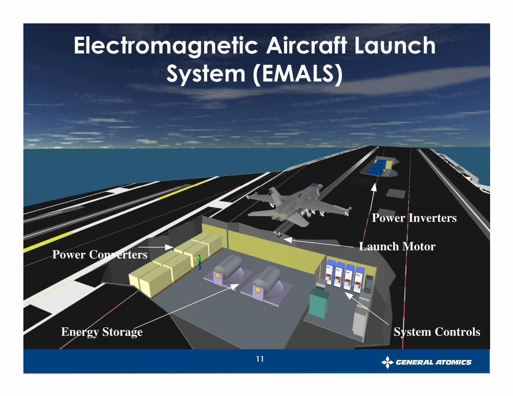
Electro-Magnetic Aircraft Launch System (EMALS)
Concept
System ControlsEnergy Storage
Power ConvertersLaunch Motor
Power Inverters
Electromagnetic Aircraft Launch System (EMALS)
12
Transportation Systems Using GA
Passive Maglev Technology
13
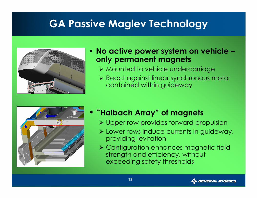
GA Passive Maglev Technology
• No active power system on vehicle –only permanent magnets� Mounted to vehicle undercarriage
� React against linear synchronous motor contained within guideway
• “Halbach Array” of magnets� Upper row provides forward propulsion
� Lower rows induce currents in guideway, providing levitation
� Configuration enhances magnetic field strength and efficiency, without exceeding safety thresholds
14
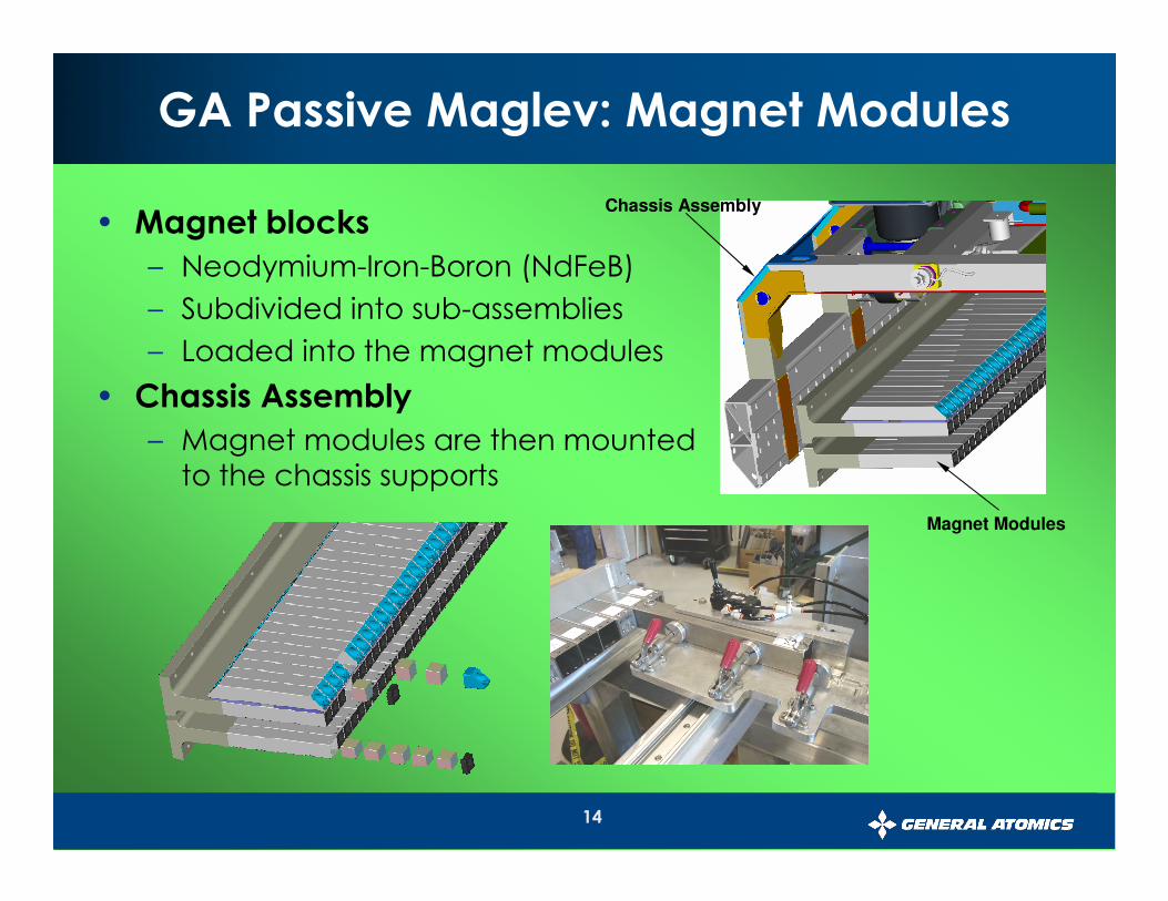
GA Passive Maglev: Magnet Modules
• Magnet blocks
– Neodymium-Iron-Boron (NdFeB)
– Subdivided into sub-assemblies
– Loaded into the magnet modules
• Chassis Assembly
– Magnet modules are then mounted
to the chassis supports
Chassis Assembly
Magnet Modules
15
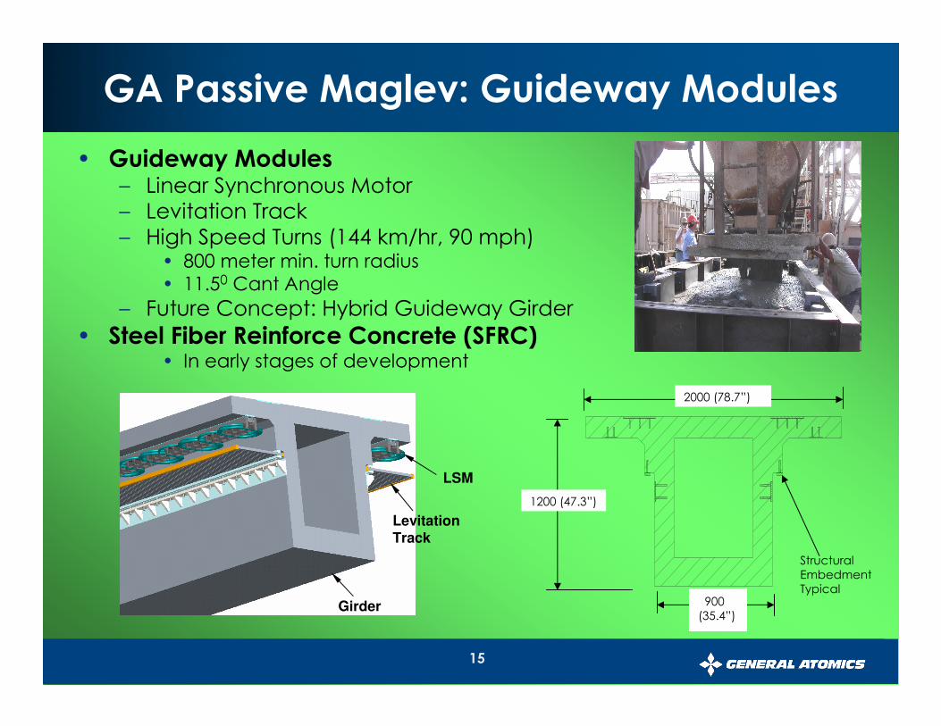
• Guideway Modules– Linear Synchronous Motor
– Levitation Track
– High Speed Turns (144 km/hr, 90 mph)• 800 meter min. turn radius
• 11.50 Cant Angle
– Future Concept: Hybrid Guideway Girder
• Steel Fiber Reinforce Concrete (SFRC)• In early stages of development
LevitationTrack
Structural
Embedment
Typical
1200 (47.3”)
2000 (78.7”)
900
(35.4”)
LSM
Girder
GA Passive Maglev: Guideway Modules
16
• Lighter, less expensive vehicle
�No active onboard power systems – just permanent magnets
�Especially beneficial for high throughput applications, e.g. cargo movement
• Lighter, less expensive guideway
�Vehicle weight that must be supported is lower
�Large air gap reduces complexity of guideway manufacturing
�Especially beneficial in urban areas where large guidewaysupports would be difficult to site or intrusive
• No high power pickup system (“third rail”) required
GA Passive Maglev:Unique Benefits of Technology
Particularly attractive for passenger and goods movement in congested metropolitan areas
17
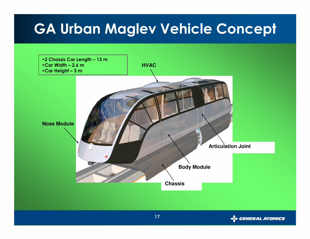
GA Urban Maglev Vehicle Concept
Nose Module
Body Module
HVAC
Articulation Joint
Chassis
•2 Chassis Car Length – 13 m•Car Width – 2.6 m•Car Height – 3 m
18
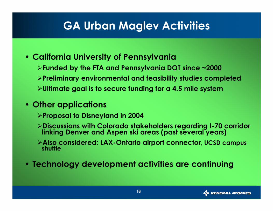
• California University of Pennsylvania
�Funded by the FTA and Pennsylvania DOT since ~2000
�Preliminary environmental and feasibility studies completed
�Ultimate goal is to secure funding for a 4.5 mile system
• Other applications
�Proposal to Disneyland in 2004
�Discussions with Colorado stakeholders regarding I-70 corridor linking Denver and Aspen ski areas (past several years)
�Also considered: LAX-Ontario airport connector, UCSD campus shuttle
• Technology development activities are continuing
GA Urban Maglev Activities
19
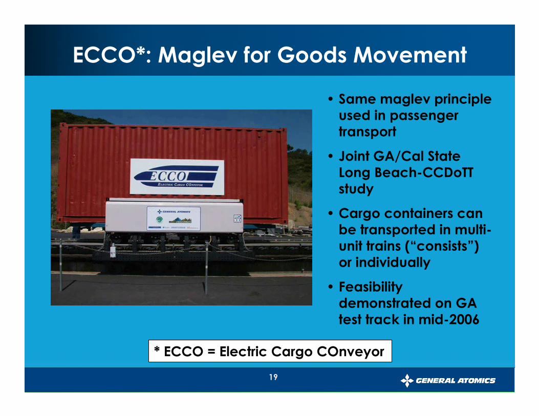
ECCO*: Maglev for Goods Movement
• Same maglev principle used in passenger transport
• Joint GA/Cal State Long Beach-CCDoTTstudy
• Cargo containers can be transported in multi-unit trains (“consists”) or individually
• Feasibility demonstrated on GA test track in mid-2006
* ECCO = Electric Cargo COnveyor
20
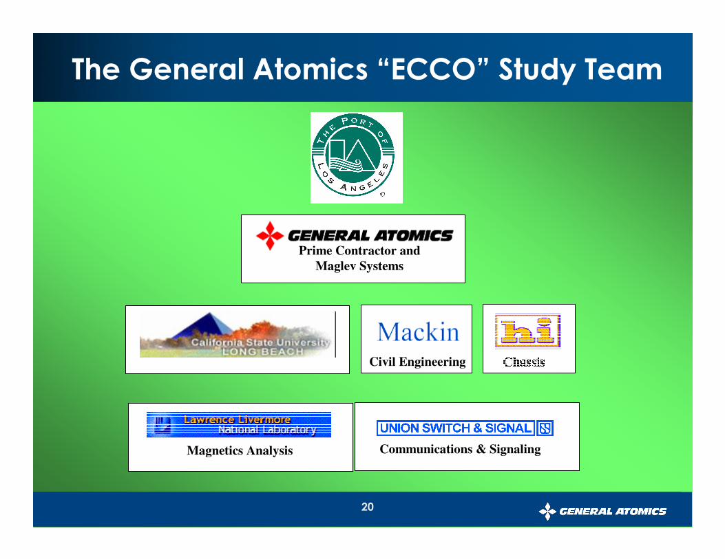
The General Atomics “ECCO” Study Team
Civil EngineeringSystem Architecture
Communications & SignalingMagnetics Analysis
Prime Contractor and
Maglev Systems
21
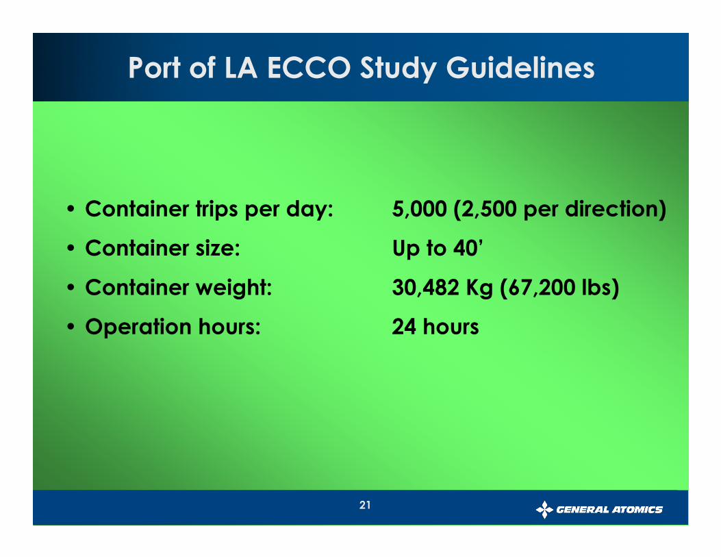
• Container trips per day: 5,000 (2,500 per direction)
• Container size: Up to 40’
• Container weight: 30,482 Kg (67,200 lbs)
• Operation hours: 24 hours
Port of LA ECCO Study Guidelines
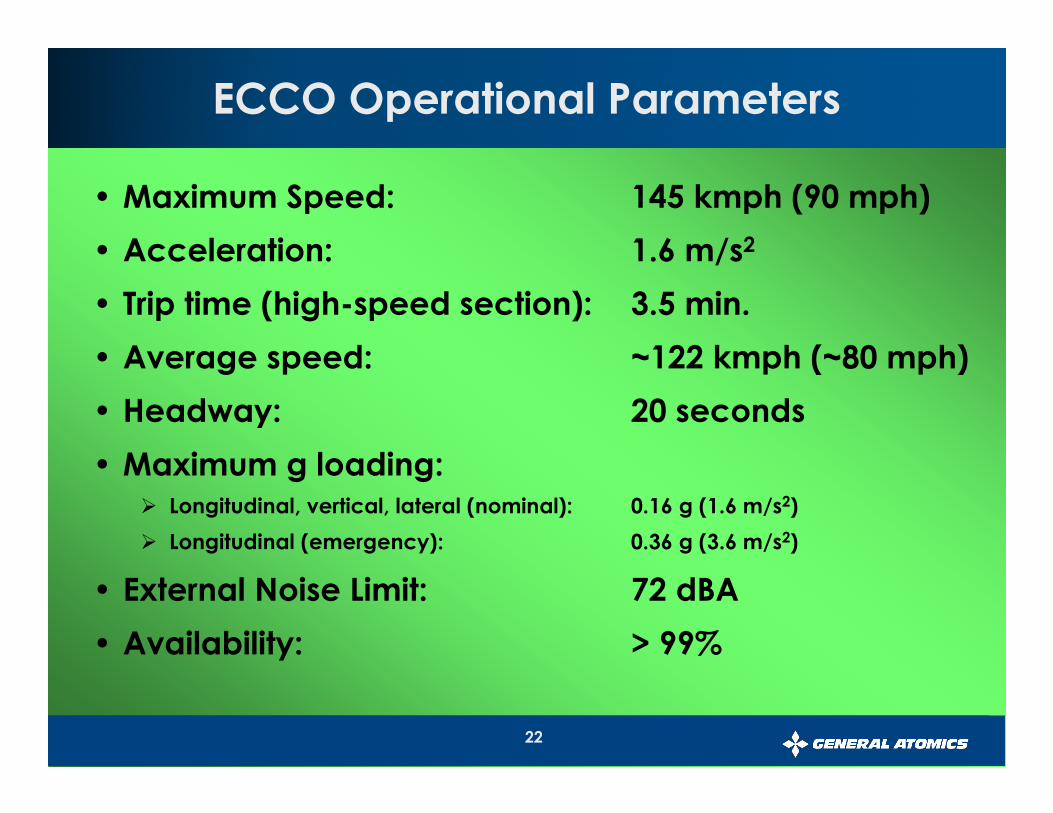
22
ECCO Operational Parameters
• Maximum Speed: 145 kmph (90 mph)
• Acceleration: 1.6 m/s2
• Trip time (high-speed section): 3.5 min.
• Average speed: ~122 kmph (~80 mph)
• Headway: 20 seconds
• Maximum g loading:� Longitudinal, vertical, lateral (nominal): 0.16 g (1.6 m/s2)
� Longitudinal (emergency): 0.36 g (3.6 m/s2)
• External Noise Limit: 72 dBA
• Availability: > 99%
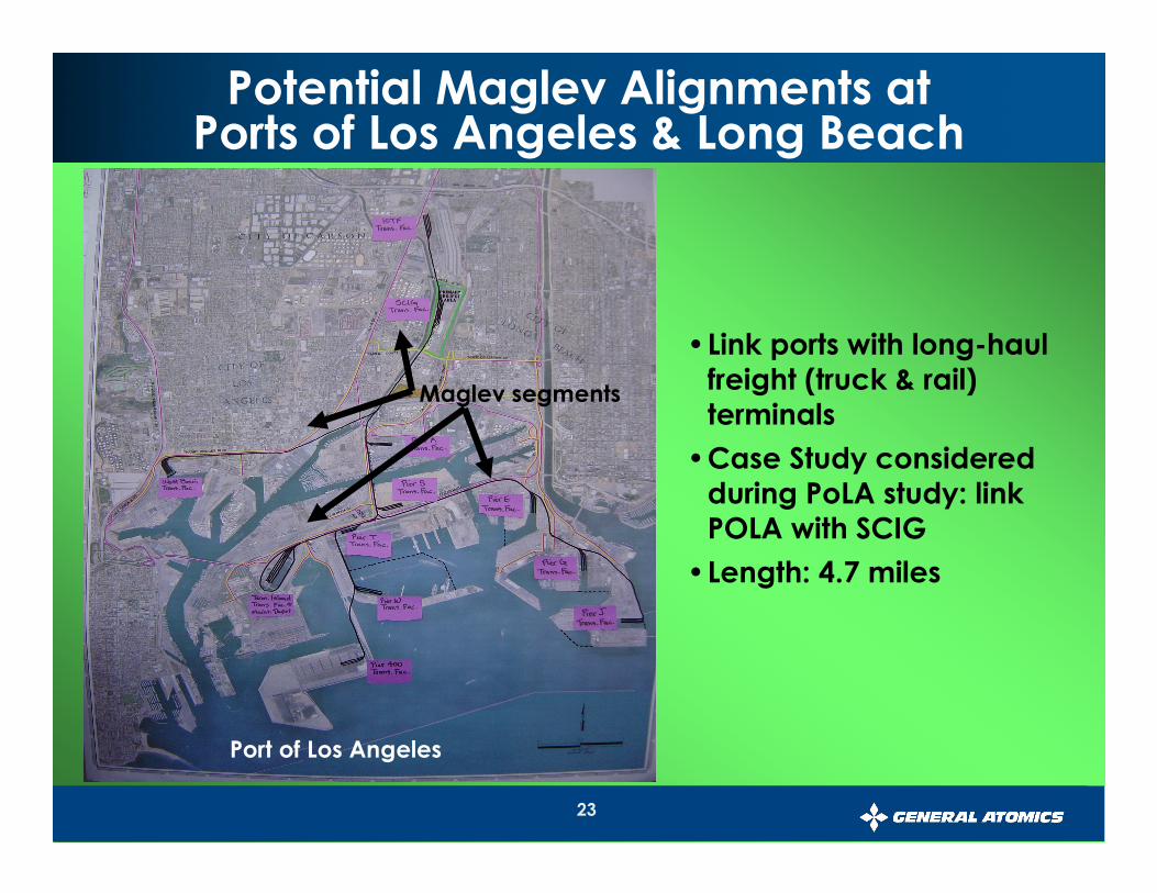
23
Potential Maglev Alignments atPorts of Los Angeles & Long Beach
•Link ports with long-haul freight (truck & rail) terminals
•Case Study considered during PoLA study: link POLA with SCIG
•Length: 4.7 miles
Port of Los Angeles
Maglev segments
24
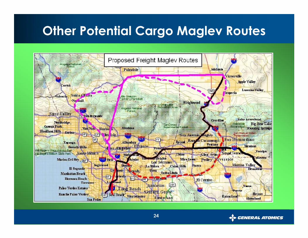
Other Potential Cargo Maglev Routes
25
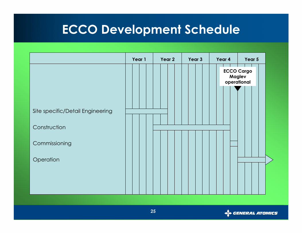
ECCO Development Schedule
Site specific/Detail Engineering
Year 1
Construction
Commissioning
Operation
Year 2 Year 3 Year 4 Year 5
ECCO Cargo Maglev
operational
26
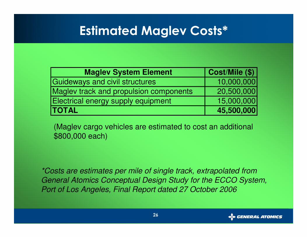
Estimated Maglev Costs*
Maglev System Element Cost/Mile ($)
Guideways and civil structures 10,000,000
Maglev track and propulsion components 20,500,000
Electrical energy supply equipment 15,000,000TOTAL 45,500,000
(Maglev cargo vehicles are estimated to cost an additional $800,000 each)
*Costs are estimates per mile of single track, extrapolated fromGeneral Atomics Conceptual Design Study for the ECCO System, Port of Los Angeles, Final Report dated 27 October 2006
27
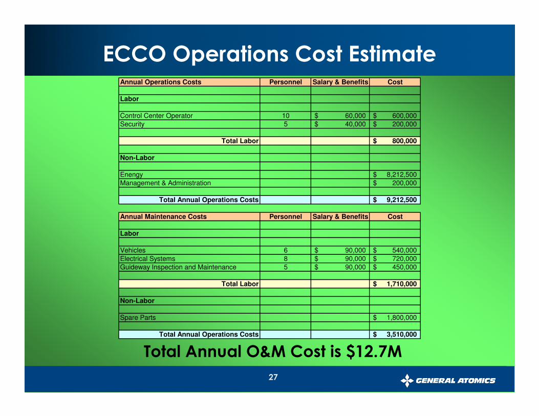
Total Annual O&M Cost is $12.7M
Annual Operations Costs Personnel Salary & Benefits Cost
Labor
Control Center Operator 10 60,000$ 600,000$
Security 5 40,000$ 200,000$
Total Labor 800,000$
Non-Labor
Enengy 8,212,500$
Management & Administration 200,000$
Total Annual Operations Costs 9,212,500$
Annual Maintenance Costs Personnel Salary & Benefits Cost
Labor
Vehicles 6 90,000$ 540,000$
Electrical Systems 8 90,000$ 720,000$
Guideway Inspection and Maintenance 5 90,000$ 450,000$
Total Labor 1,710,000$
Non-Labor
Spare Parts 1,800,000$
Total Annual Operations Costs 3,510,000$
ECCO Operations Cost Estimate
28
• Environmental Protection
•Clean, all-electric operation
•Eliminates diesel exhaust from >1M truck trips per year
•Secondary benefits from reducing local traffic congestion
• Economical
•Automated transport reduces labor costs
•Fuel savings are much greater than electricity costs
• Energy efficient
•Passive maglev technology minimizes vehicle weight
•Electric grid power will displace >1M gallons/year of fuel
•Secondary benefits from reducing local traffic congestion
Potential Benefits of “ECCO” Maglev atPorts of Los Angeles and Long Beach
29
Linear Induction Motor Rail
(LIM™-Rail) Systems

30
• Goal: Adapt linear motor technologies to existing rail
�Take advantage of clean, efficient linear induction motor technology
�Make use of existing rail infrastructure to minimize implementation time and costs
• Solution: LIM-Rail™ system for rail transport
�Embed linear induction motor modules into rail bed
�Propulsion achieved by inducing an electric current in aluminum plates mounted to the underside of vehicles
• Advantages over other rail electrification methods
�No electrified third rails or overhead power lines – fewer safety issues and less intrusive
�No motors or active power systems onboard vehicles –reduces weight and cost of vehicles
LIM-Rail™: Linear Induction Motor Rail

31
• Rail component
�Linear induction motors (LIMs) can propel objects using same principle used to spin rotors of AC induction motors
�Built into hardened modules and fastened to railroad ties between rails, LIMs can propel rail vehicles along tracks
• Vehicle component
�Reactive plates made of any conductive material (typically aluminum) can be used to propel vehicles
�Reactive plates are mounted to undersides of vehicles
�Moving magnetic fields generated by LIMs induce currents in reactive plates, which are then pulled along the LIM segment
• Principles are proven
�Linear motors are used in several rail systems around the world
�LIM-Rail™ reverses the usual method of linear motor operation, placing the linear motor in the track instead of on the vehicle
LIM-Rail™: Principles of Operation
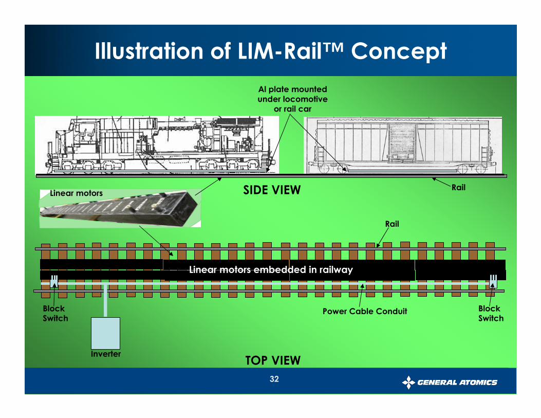
32
Illustration of LIM-Rail™ Concept
Al plate mounted under locomotive
or rail car
Rail SIDE VIEW
TOP VIEW
Linear motors embedded in railway
Inverter
Block Switch
Block Switch
Power Cable Conduit
Rail
Linear motors
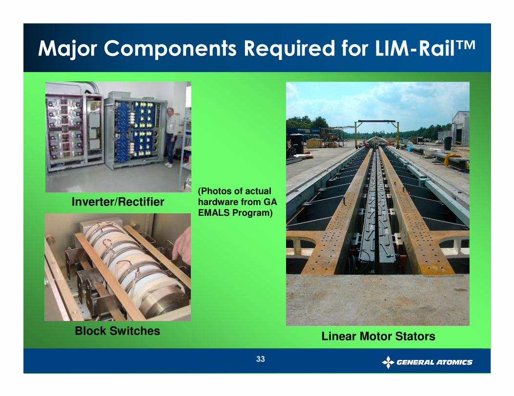
33
Inverter/Rectifier
Block Switches Linear Motor Stators
Major Components Required for LIM-Rail™
(Photos of actual hardware from GA EMALS Program)
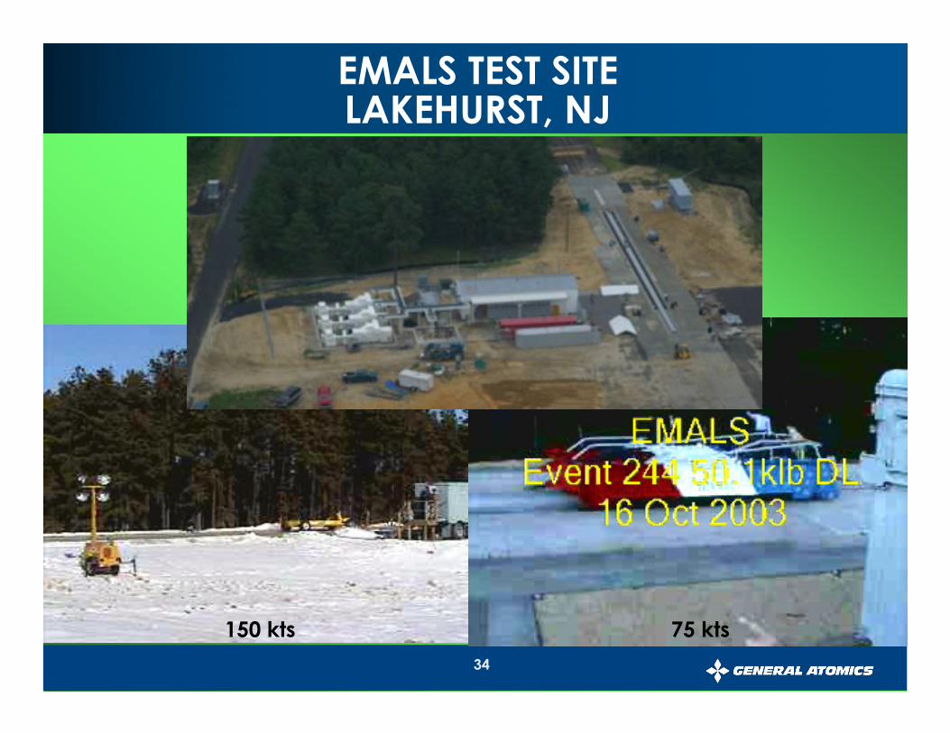
34
EMALS TEST SITELAKEHURST, NJ
150 kts 75 kts
35
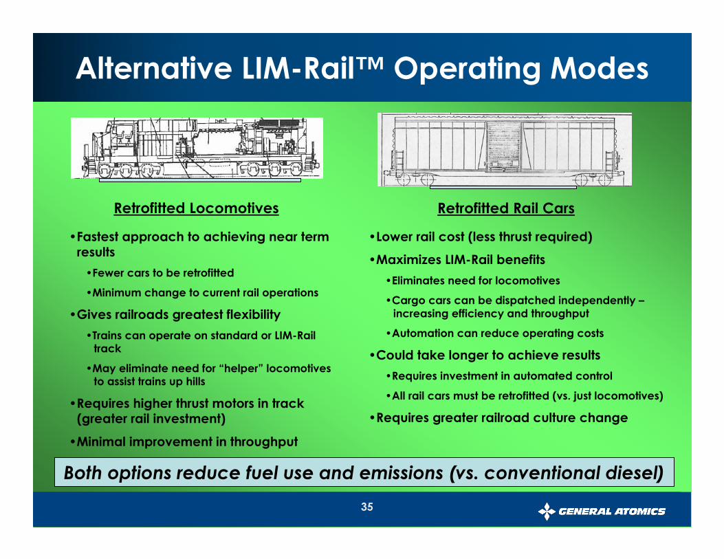
Alternative LIM-Rail™ Operating Modes
Retrofitted Locomotives
•Fastest approach to achieving near term results
•Fewer cars to be retrofitted
•Minimum change to current rail operations
•Gives railroads greatest flexibility
•Trains can operate on standard or LIM-Rail track
•May eliminate need for “helper” locomotives to assist trains up hills
•Requires higher thrust motors in track (greater rail investment)
•Minimal improvement in throughput
Retrofitted Rail Cars
•Lower rail cost (less thrust required)
•Maximizes LIM-Rail benefits
•Eliminates need for locomotives
•Cargo cars can be dispatched independently –increasing efficiency and throughput
•Automation can reduce operating costs
•Could take longer to achieve results
•Requires investment in automated control
•All rail cars must be retrofitted (vs. just locomotives)
•Requires greater railroad culture change
Both options reduce fuel use and emissions (vs. conventional diesel)
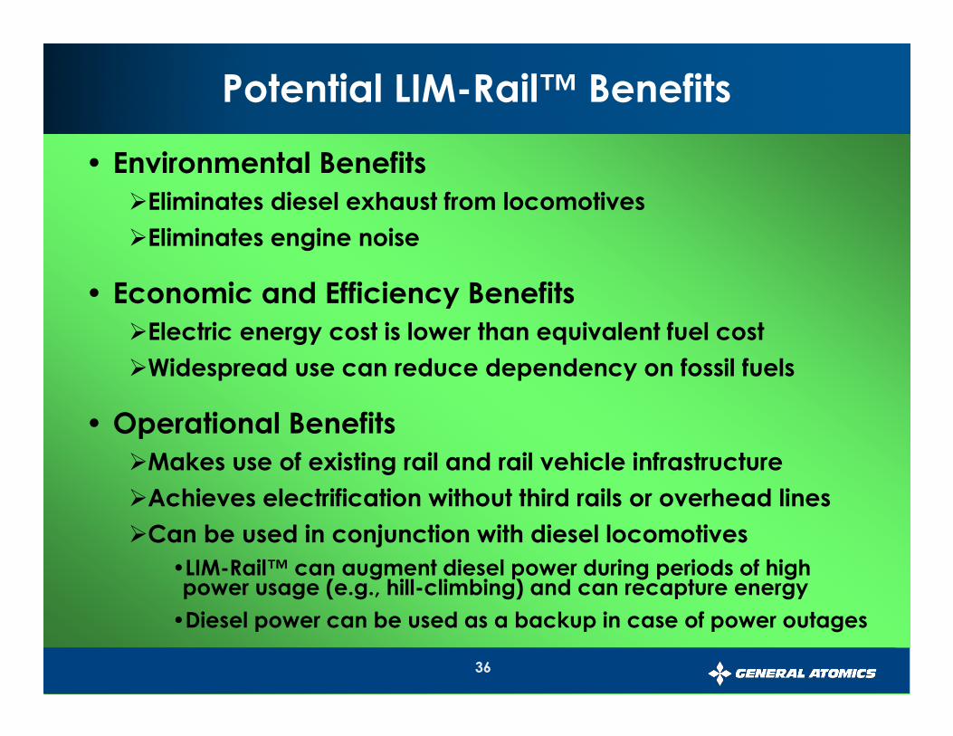
36
• Environmental Benefits
�Eliminates diesel exhaust from locomotives
�Eliminates engine noise
• Economic and Efficiency Benefits
�Electric energy cost is lower than equivalent fuel cost
�Widespread use can reduce dependency on fossil fuels
• Operational Benefits
�Makes use of existing rail and rail vehicle infrastructure
�Achieves electrification without third rails or overhead lines
�Can be used in conjunction with diesel locomotives
•LIM-Rail™ can augment diesel power during periods of high power usage (e.g., hill-climbing) and can recapture energy
•Diesel power can be used as a backup in case of power outages
Potential LIM-Rail™ Benefits
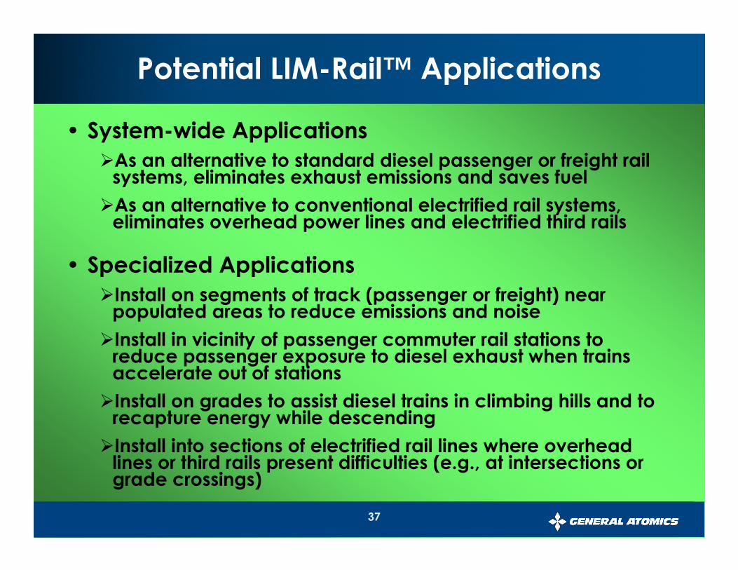
37
• System-wide Applications
�As an alternative to standard diesel passenger or freight rail systems, eliminates exhaust emissions and saves fuel
�As an alternative to conventional electrified rail systems, eliminates overhead power lines and electrified third rails
• Specialized Applications
�Install on segments of track (passenger or freight) near populated areas to reduce emissions and noise
�Install in vicinity of passenger commuter rail stations to reduce passenger exposure to diesel exhaust when trains accelerate out of stations
�Install on grades to assist diesel trains in climbing hills and to recapture energy while descending
�Install into sections of electrified rail lines where overhead lines or third rails present difficulties (e.g., at intersections or grade crossings)
Potential LIM-Rail™ Applications
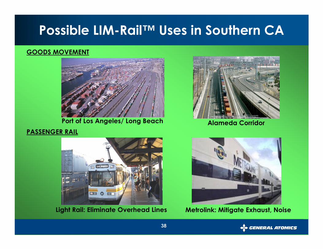
38
Possible LIM-Rail™ Uses in Southern CA
Port of Los Angeles/ Long Beach Alameda Corridor
GOODS MOVEMENT
Light Rail: Eliminate Overhead Lines Metrolink: Mitigate Exhaust, Noise
PASSENGER RAIL
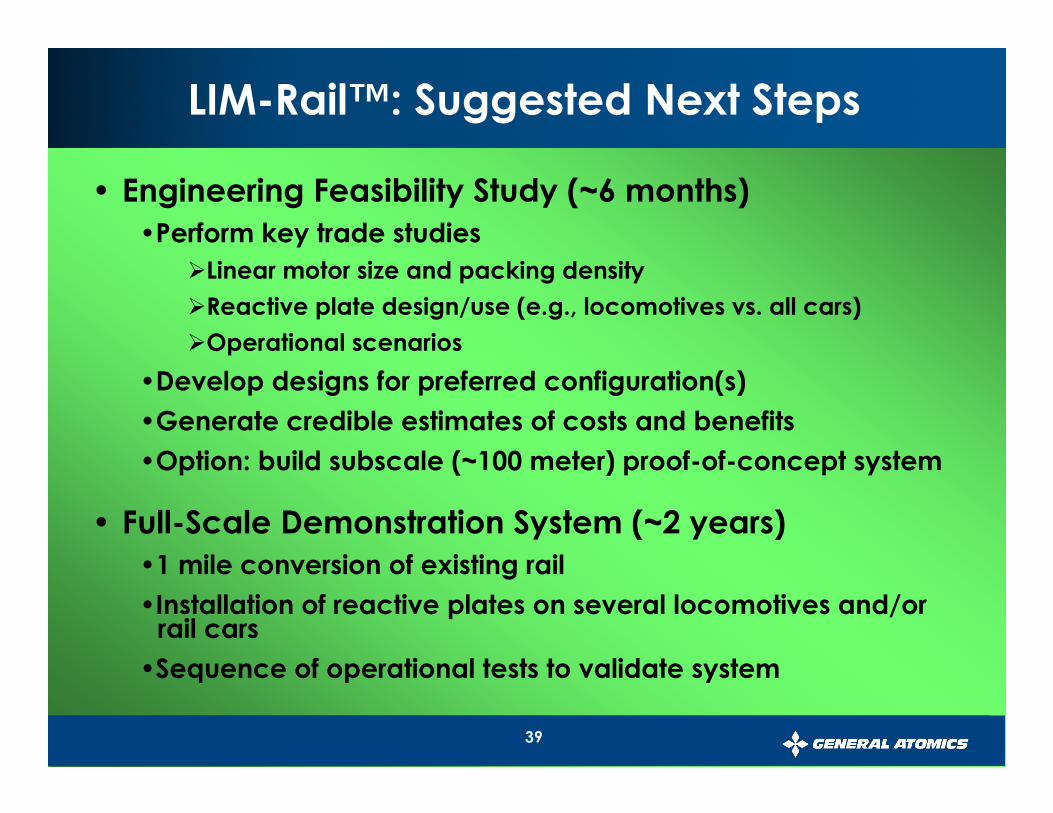
39
• Engineering Feasibility Study (~6 months)
•Perform key trade studies
�Linear motor size and packing density
�Reactive plate design/use (e.g., locomotives vs. all cars)
�Operational scenarios
•Develop designs for preferred configuration(s)
•Generate credible estimates of costs and benefits
•Option: build subscale (~100 meter) proof-of-concept system
• Full-Scale Demonstration System (~2 years)
•1 mile conversion of existing rail
•Installation of reactive plates on several locomotives and/or rail cars
•Sequence of operational tests to validate system
LIM-Rail™: Suggested Next Steps
40
Conclusions
41
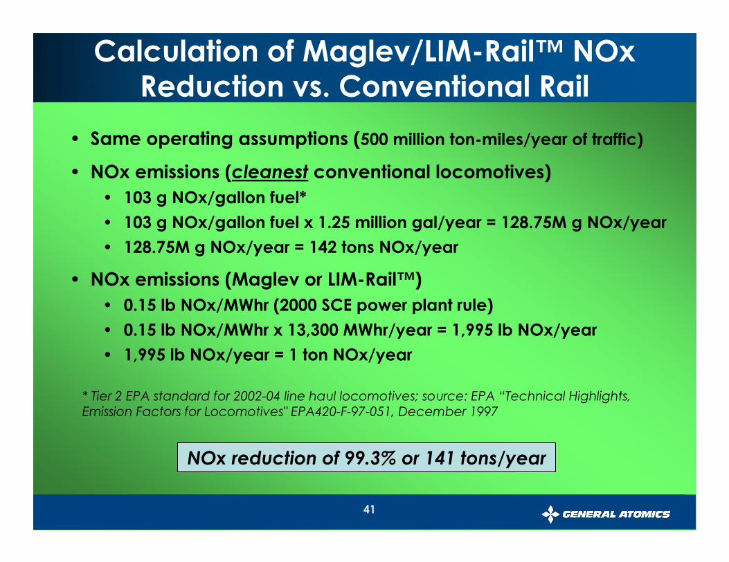
Calculation of Maglev/LIM-Rail™ NOxReduction vs. Conventional Rail
• Same operating assumptions (500 million ton-miles/year of traffic)
• NOx emissions (cleanest conventional locomotives)
• 103 g NOx/gallon fuel*
• 103 g NOx/gallon fuel x 1.25 million gal/year = 128.75M g NOx/year
• 128.75M g NOx/year = 142 tons NOx/year
• NOx emissions (Maglev or LIM-Rail™)
• 0.15 lb NOx/MWhr (2000 SCE power plant rule)
• 0.15 lb NOx/MWhr x 13,300 MWhr/year = 1,995 lb NOx/year
• 1,995 lb NOx/year = 1 ton NOx/year
NOx reduction of 99.3% or 141 tons/year
* Tier 2 EPA standard for 2002-04 line haul locomotives; source: EPA “Technical Highlights, Emission Factors for Locomotives" EPA420-F-97-051, December 1997

42
Calculation of Maglev/LIM-Rail™ Fuel Savings vs. Conventional Rail
• Operating assumptions
• 10-mile route
• 1 million cargo cars per year
• 50 tons/car → 500 million ton-miles of traffic per year
• Diesel fuel cost (conventional locomotives)
• 400 ton-miles/gallon fuel
• 500 million ton-miles ÷ 400 ton-miles/gal = 1.25 million gal/year
• 1.25 million gal/year x $2.50/gal = $3.13M/year diesel fuel cost
• Electricity cost (Maglev or LIM-Rail™)
• 0.5 lb diesel/Hp-hr → 14 Hp-hr.gal → 10.6 kWhr/gal
• 400 ton-miles/gal ÷ 10.6 kWhr/gal = 37.7 ton-miles/kWhr
• 500 million ton-miles ÷ 37.7 ton-miles/kWhr = 13.3M kWhr
• 13.3M kWhr x $0.085/kWhr = $1.13M/year electricity cost
$2 million/year in diesel fuel savings
43
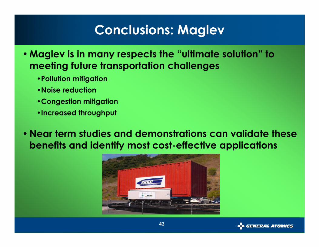
Conclusions: Maglev
•Maglev is in many respects the “ultimate solution” to meeting future transportation challenges
•Pollution mitigation
•Noise reduction
•Congestion mitigation
•Increased throughput
•Near term studies and demonstrations can validate these benefits and identify most cost-effective applications
44
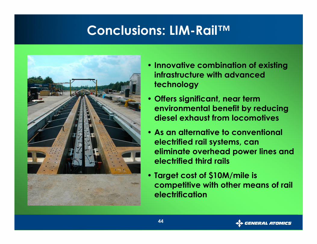
• Innovative combination of existing infrastructure with advanced technology
• Offers significant, near term environmental benefit by reducing diesel exhaust from locomotives
• As an alternative to conventional electrified rail systems, can eliminate overhead power lines and electrified third rails
• Target cost of $10M/mile is competitive with other means of rail electrification
Conclusions: LIM-Rail™


![Maglev resumé]](https://static.fdocuments.net/doc/165x107/5571f8a849795991698dd702/maglev-resume.jpg)