MF 4700, MF 5700, MF 6700 12 x 12 Power Shuttle Global Series

MAE 4700/5700 (Fall 2009) Homework 1 Plane trusses
Finite Element Analysis for Mechanical & Aerospace Design Page 1 of 17
Problem 1 - Analysis of a three bar structure (hand calculation)
Figure 1: Three-bar problem
Three bars are joined as shown in Figure 1. The left and right ends are both constrained,
i.e. prescribed displacement is zero at both ends. There is a force of 5 N acting on the
middle node. The nodes are numbered starting with the nodes where displacements are
prescribed. You may consider ( )ek as the spring constant and is known.
a. Assemble the global stiffness and force matrix.
b. Partition the system and solve for the nodal displacements 3u .
c. Compute the reaction forces.
Solution:
The element stiffness matrices are
where the global numbers corresponding to the element nodes are indicated above each
column and to the right of the row.
By direct assembly, the global stiffness matrix is
The displacement and force matrices for the system are
The global system of equation is given by

MAE 4700/5700 (Fall 2009) Homework 1 Plane trusses
Finite Element Analysis for Mechanical & Aerospace Design Page 2 of 17
As the first two displacements are prescribed, we partition after two rows and columns
or
Where
The reduced system of equations is given by
which yields
The unknown reaction vector is
(1) (2)1
(1) (2) (3)(3)2
5E E E EF F
r k k
r k k kk
r K d K d
Problem 2 - Analysis of a plane truss structure (hand calculation)
Figure 2: A plane truss structure
Consider the truss structure given in Figure 2. Nodes A and B are fixed. A force equal to
10 N acts in the positive x -direction at node C. Coordinates of joints are given in meters.
Young’s modulus E and the cross-sectional area A constants.
a. Assemble the global stiffness and force matrix.
b. Partition the system and solve for the nodal displacements.
c. Compute the stresses and reactions.
(1) (2)
(3)
(4)
1 2
34

MAE 4700/5700 (Fall 2009) Homework 1 Plane trusses
Finite Element Analysis for Mechanical & Aerospace Design Page 3 of 17
Solution:
Element 1:
Element 1 is numbered with global nodes 1 and 4. (1) (1)cos90 0, sin90 1, 1,l k EA
(1)
0 0 0 0
0 1 0 1
0 0 0 0
0 1 0 1
K EA
Element 2:
Element 2 is numbered with global nodes 2 and 4.
(2) (2)1 1cos135 , sin135 , 2,
2 2 2
EAl k
(2)
1 1 1 1
2 2 2 2
1 1 1 1
2 2 2 2
1 1 1 12
2 2 2 2
1 1 1 1
2 2 2 2
EAK
Element 3:
Element 3 is numbered with global nodes 3 and 4 (3) (3)cos180 1, sin0 0, 1,l k EA
(3)
1 0 1 0
0 0 0 0
1 0 1 0
0 0 0 0
K EA
Element 4:
Element 4 is numbered with global nodes 2 and 3 (4) (4)cos90 0, sin90 1, 1,l k EA
(4)
0 0 0 0
0 1 0 1
0 0 0 0
0 1 0 1
K EA
Direct assembly:

MAE 4700/5700 (Fall 2009) Homework 1 Plane trusses
Finite Element Analysis for Mechanical & Aerospace Design Page 4 of 17
0 0 0 0 0 0 0 0
0 1 0 0 0 0 0 1
1 1 1 10 0 0 0
2 2 2 2 2 2 2 2
1 1 1 10 0 1 0 1
2 2 2 2 2 2 2 2
0 0 0 0 1 0 1 0
0 0 0 1 0 1 0 0
1 1 1 10 0 1 0 1
2 2 2 2 2 2 2 2
1 1 1 10 1 0 0 1
2 2 2 2 2 2 2 2
EA
K
and
1
1
2
2
3
3
4
4
0 0
0 0
0 0
0 0
10 0
0 0
0 0
0 0
x
y
x
y
x
y
x
y
r
r
r
r
u
u
u
u
d f r
Once again notice that if the external force component at a node is prescribed, then the
corresponding displacement component at that node is unknown. On the other hand if a
displacement component at a node is prescribed, then the corresponding force component
at that node is an unknown reaction.
The global system is partitioned after four rows and four columns:
E EF EE
T
EF F FF
K K rd
K K fd
3 3
3 3
4 4
4 4
0 10
0 0, , ,
0 0
0 0
x x
y y
x x
y y
u r
u r
u r
u r
E F F Ed d f r

MAE 4700/5700 (Fall 2009) Homework 1 Plane trusses
Finite Element Analysis for Mechanical & Aerospace Design Page 5 of 17
1 0 1 0 0 0 0 0
0 1 0 0 0 0 0 1
1 1 1 1,1 0 1 0 0
2 2 2 2 2 2 2 2
1 1 1 10 0 1 0 1
2 2 2 2 2 2 2 2
F EFK K
The unknown displacement matrix if found from the solution of the reduced system of
equations:
3
3
4
4
1 0 1 0
100 1 0 0
01 11 0 1
02 2 2 2
1 1 00 0 1
2 2 2 2
x
y
x
y
u
uEA
u
u
and is given by
3
3
4
4
20 20 2
01
10 20 2
10
x
y
x
y
u
u
u EA
u
The unknown reaction matrix r is
3
3
4
4
0 0 0 0
20 20 2 00 0 0 1
0 101 10 0
102 2 2 2 10 20 2
1 1 10100 12 2 2 2
x
y
x
y
r
r
r
r
E E E EF Fr K d K d
It can be easily verified that the equilibrium equations are satisfied:
20, 0, 0x yF F M
Finally, in the postprocessing step the stresses in the four elements are computed as
follows:

MAE 4700/5700 (Fall 2009) Homework 1 Plane trusses
Finite Element Analysis for Mechanical & Aerospace Design Page 6 of 17
1
12 1
2
2
1 0 1 0 1 0 1 0
cos sin cos sin .
e
x
ee e e eye e x x
ee e e
x
e
y
ee e e e
e
u
uu u E EE
ul l l
u
E
l
e e
e
T d
d
For element 1, we have
(1) (1) (1)
1
1(1)
4
4
(1)
90 cos 0,sin 1 ,
0
01
10 20 2
10
0
0 1 100 1 0 1
10 20 2
10
x
y
x
y
u
u
u EA
u
A A
d
For element 2, we have
(2) (2) (2)1 1135 cos ,sin ,
2 2
2
2(2)
4
4
0
01
10 20 2
10
x
y
x
y
u
u
u EA
u
d
(2)
0
01 1 1 1 1 1 10 2
2 2 2 2 2 10 20 2
10
A A
For element 3, we have
(3) (3) (3)180 cos 1,sin 0 ,
3
3(3)
4
4
20 20 2
01
10 20 2
10
x
y
x
y
u
u
u EA
u
d

MAE 4700/5700 (Fall 2009) Homework 1 Plane trusses
Finite Element Analysis for Mechanical & Aerospace Design Page 7 of 17
(3)
20 20 2
0 1 101 0 1 0
10 20 2
10
A A
For element 4, we have
(4) (1) (1)
2
2(4)
3
3
(1)
90 cos 0,sin 1 ,
0
01
20 20 2
0
0
0 10 1 0 1 0
20 20 2
0
x
y
x
y
u
u
u EA
u
A
d
Problem 3 - Analysis of two plane truss structures (MatLab)
Figure 3: Two plane truss structures
Using the MATLAB finite element code, find the displacements and stresses in the two
truss structures given in Figure 3. Plot the deformed structure with MATLAB. For truss
structure (b), exploit the symmetry. For the two trusses, check the equilibrium at node 1.
The Young’s modulus 1110E Pa, cross sectional areas of all bars 2 210A m ,
forces 310F N and 2L m.

MAE 4700/5700 (Fall 2009) Homework 1 Plane trusses
Finite Element Analysis for Mechanical & Aerospace Design Page 8 of 17
Solution:
(a) After modifying the input data and grid,
f(3) = P;
E = ones(nel,1)*1e11;
A = ones(nel,1)*1e-2;
debc = [5, 6, 7, 8, 9, 10];
etc.
Nodes = [1, 4, 0, 2, 4;
sqrt(3), 2, 0, 0, 0];
Elems=[1, 1, 1, 2, 2
3, 4, 2, 4, 5];
we obtain the following results:
Node# x-displacement(m) y-displacement(m)
1 2.082758e-006 6.200815e-008
2 3.763022e-006 -1.051633e-006
3 0 0
4 0 0
5 0 0
Node# x-reaction force (Nt) y-reaction force (Nt)
3 -273.769936 -474.183439
4 -726.230064 -51.633121
5 0.000000 525.816561
Element # Strain Stress (Pa) Force (nt)
1 5.475399e-007 54753.987269 547.539873
2 -4.938392e-007 -49383.923641 -493.839236
3 5.227623e-007 52276.230829 522.762308
4 6.778473e-007 67784.733254 677.847333
5 -5.258166e-007 -52581.656067 -525.816561
It is easy to verify that the overall equilibrium is satisfied and also at node 1.
The deformed shape is
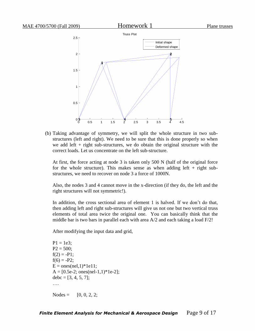
MAE 4700/5700 (Fall 2009) Homework 1 Plane trusses
Finite Element Analysis for Mechanical & Aerospace Design Page 9 of 17
0 0.5 1 1.5 2 2.5 3 3.5 4 4.50
0.5
1
1.5
2
2.5
1
3
1
4
1
22
4
2
5
Truss Plot
1
3
1
4
1
22
4
2
5
Initial shape
Deformed shape
(b) Taking advantage of symmetry, we will split the whole structure in two sub-
structures (left and right). We need to be sure that this is done properly so when
we add left + right sub-structures, we do obtain the original structure with the
correct loads. Let us concentrate on the left sub-structure.
At first, the force acting at node 3 is taken only 500 N (half of the original force
for the whole structure). This makes sense as when adding left + right sub-
structures, we need to recover on node 3 a force of 1000N.
Also, the nodes 3 and 4 cannot move in the x-direction (if they do, the left and the
right structures will not symmetric!).
In addition, the cross sectional area of element 1 is halved. If we don’t do that,
then adding left and right sub-structures will give us not one but two vertical truss
elements of total area twice the original one. You can basically think that the
middle bar is two bars in parallel each with area A/2 and each taking a load F/2!
After modifying the input data and grid,
P1 = 1e3;
P2 = 500;
f(2) = -P1;
f(6) = -P2;
E = ones(nel,1)*1e11;
A = [0.5e-2; ones(nel-1,1)*1e-2];
debc = [3, 4, 5, 7];
….
Nodes = [0, 0, 2, 2;

MAE 4700/5700 (Fall 2009) Homework 1 Plane trusses
Finite Element Analysis for Mechanical & Aerospace Design Page 10 of 17
2, 0, 2, 0];
Elems=[3, 1, 2, 1, 2, 1;
4, 3, 3, 2, 4, 4];
….
we obtain the following results:
Node# x-displacement(m) y-displacement(m)
1 8.578644e-008 -2.085786e-006
2 0 0
3 0 -2.585786e-006
4 0 -2.414214e-006
Node# x-reaction force (Nt) y-reaction force (Nt)
2 457.106781 1500.000000
3 -500.000000 0
4 42.893219 0
Element # Strain Stress (Pa) Force (nt)
1 -8.578644e-008 -8578.643763 -42.893219
2 -4.289322e-008 -4289.321881 -42.893219
3 -6.464466e-007 -64644.660941 -646.446609
4 -1.042893e-006 -104289.321881 -1042.893219
5 0 0 0
6 6.066017e-008 6066.017178 60.660172
It is easy to verify that the overall equilibrium is satisfied as well as equilibrium at node
1.
The deformed shape is

MAE 4700/5700 (Fall 2009) Homework 1 Plane trusses
Finite Element Analysis for Mechanical & Aerospace Design Page 11 of 17
0 0.2 0.4 0.6 0.8 1 1.2 1.4 1.6 1.8 2-0.5
0
0.5
1
1.5
2
2.5
3
4
1 3
2
31
22 4
1
4
Truss Plot
Initial shape
Deformed shape
Here are the results from the full structure.
Node# x-displacement(m) y-displacement(m)
1 8.578644e-008 -2.085786e-006
2 0 0
3 6.908279e-023 -2.585786e-006
4 8.957883e-023 -2.414214e-006
5 -8.578644e-008 -2.085786e-006
6 0 0
The deformed shape is

MAE 4700/5700 (Fall 2009) Homework 1 Plane trusses
Finite Element Analysis for Mechanical & Aerospace Design Page 12 of 17
0 0.5 1 1.5 2 2.5 3 3.5 4-0.5
0
0.5
1
1.5
2
2.5
3
4
1 3
2
31
22 4
1
4
3 5
4 64
53
6
5
6
Truss Plot
Initial shape
Deformed shape
Therefore, the two results are the same.
Problem 4 (Ansys) Repeat problem 3 using ANSYS
Solution:
The truss problem can be solved by following the steps in the tutorial at
https://confluence.cornell.edu/display/simulation/truss
Detailed commands are listed below step by step:
1. Use the APDL Product Launcher to open ANSYS;
2. Set preferences to show structural elements in GUI;
3. Add element type;
Add ≫ Structural Mass ≫ Link ≫ 2D spar1;
4. Set area:
Preprocessor≫ Element Type ≫ Add/Edit/Delete
Add ≫ Link1 ≫ Area = 0.01;
5. Specify material properties:
Preprocessor≫ Material Props ≫ Material Models
Material Model 1 ≫ Structural ≫ Linear ≫ Elastic ≫ Isotropic
EX=1e11, PRXY=0.3;

MAE 4700/5700 (Fall 2009) Homework 1 Plane trusses
Finite Element Analysis for Mechanical & Aerospace Design Page 13 of 17
6. Define nodes:
Preprocessor≫ Modeling≫ Create≫ Nodes≫ In Active CS
Input node numbers and corresponding coordinates in the XY global coordinate
system;
7. Define elements:
Preprocessor ≫ Modeling ≫ Create ≫ Elements ≫ Auto Numbered ≫ Thru
Nodes
8. Set boundary conditions:
Preprocessor ≫Loads ≫ Define Loads ≫ Apply ≫ Structural ≫ Displacement ≫
On Nodes
Apply zero displacement in X and Y directions for relevant nodes, or zero
displacement in the X direction for relevant nodes under symmetry conditions;
9. Start Loading:
Preprocessor ≫ Loads ≫ Define Loads ≫ Apply ≫ Structural ≫ Force/Moment
≫On Nodes
Input force value and direction;
10. Run Solver:
Solution ≫ Solve ≫ Current LS;
11. Plot deformed structure:
General Postproc ≫ Plot Results ≫ Deformed Shape;
12. List displacements:
General Postproc ≫ List Results ≫ Nodal Solution
Nodal Solution ≫ DOF Solution ≫ Displacement vector sum;
13. List axial stresses:
General Postproc ≫ Element Table ≫ Define Table ≫ Add ≫ By Sequence No
≫ LS, 1
General Postproc ≫ Element Table ≫ List Elem Table ≫ LS, 1
Outputs for problem 4a:
Nodal displacements obtained from ANSYS:
PRINT U NODAL SOLUTION PER NODE ***** POST1 NODAL DEGREE OF FREEDOM LISTING ***** LOAD STEP= 0 SUBSTEP= 1 TIME= 1.0000 LOAD CASE= 0 THE FOLLOWING DEGREE OF FREEDOM RESULTS ARE IN THE GLOBAL COORDINATE SYSTEM NODE UX UY UZ USUM 1 0.20829E-05 0.61996E-07 0.0000 0.20838E-05 2 0.37631E-05-0.10516E-05 0.0000 0.39073E-05 3 0.0000 0.0000 0.0000 0.0000

MAE 4700/5700 (Fall 2009) Homework 1 Plane trusses
Finite Element Analysis for Mechanical & Aerospace Design Page 14 of 17
4 0.0000 0.0000 0.0000 0.0000 5 0.0000 0.0000 0.0000 0.0000 MAXIMUM ABSOLUTE VALUES NODE 2 2 0 2 VALUE 0.37631E-05-0.10516E-05 0.0000 0.39073E-05
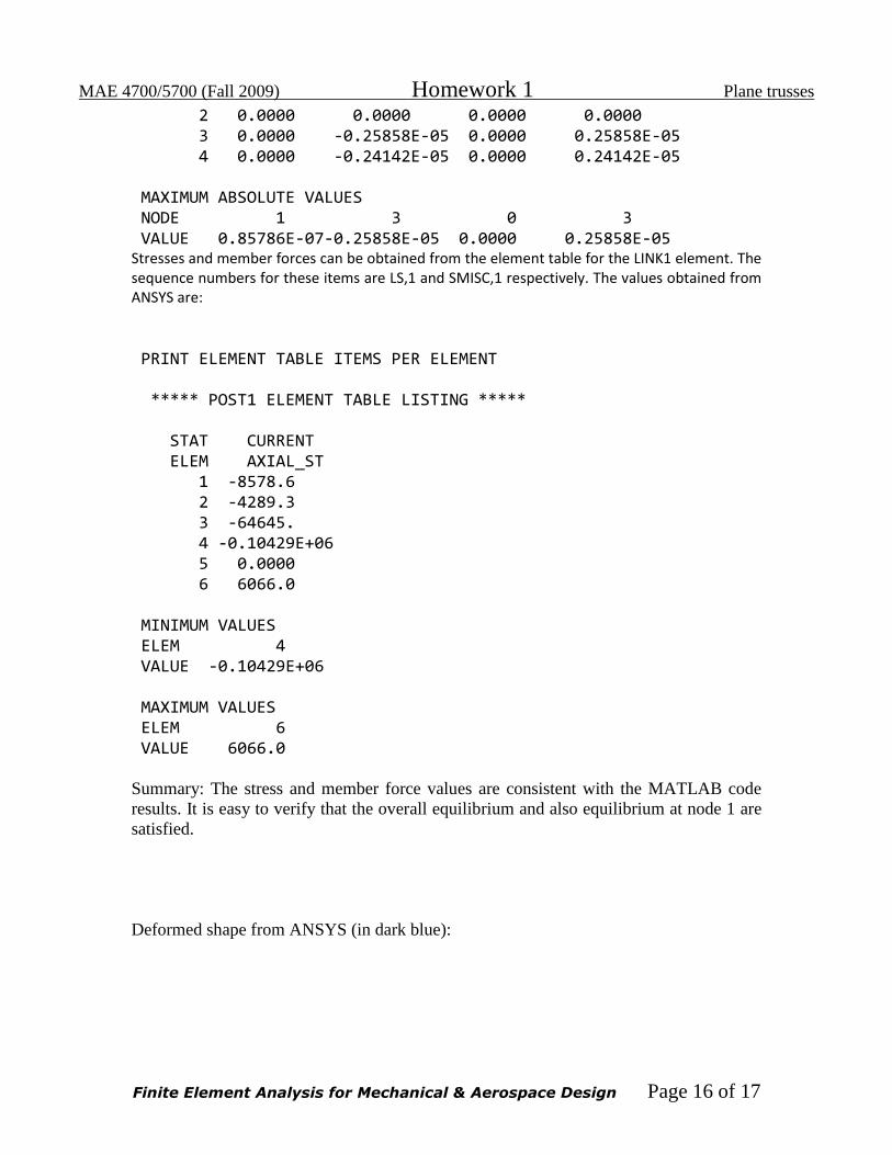
Summary: The x- and y-displacements, together with UX and UY, agree well with the
results from the MATLAB code. Stresses and member forces can be obtained from the
element table for the LINK1 element. The sequence numbers for these items are LS, 1
and SMISC, 1 respectively. The values obtained from ANSYS are:
PRINT ELEMENT TABLE ITEMS PER ELEMENT ***** POST1 ELEMENT TABLE LISTING ***** STAT CURRENT CURRENT ELEM STRESS FORCE 1 54754. 547.54 2 -49385. -493.85 3 52275. 522.75 4 67786. 677.86 5 -52582. -525.82 MINIMUM VALUES ELEM 5 5 VALUE -52582. -525.82 MAXIMUM VALUES ELEM 4 4 VALUE 67786. 677.86 Summary: The stress and member force values are consistent with the MATLAB code
results. It is easy to verify that the overall equilibrium is satisfied and also at node 1.

MAE 4700/5700 (Fall 2009) Homework 1 Plane trusses
Finite Element Analysis for Mechanical & Aerospace Design Page 15 of 17
Deformed shape from ANSYS (in dark blue):
Outputs for problem 4b:
The truss problem can be solved by following the same steps as part (a). Because of
symmetry, only the left half needs to be modeled. The force at node 3 is only 500 N and
the nodes 3 and 4 cannot move in the x direction (UX=0).
The x- and y-displacements, UX and UY, respectively, match the results from the
MATLAB code closely.
PRINT U NODAL SOLUTION PER NODE ***** POST1 NODAL DEGREE OF FREEDOM LISTING ***** LOAD STEP= 1 SUBSTEP= 1 TIME= 1.0000 LOAD CASE= 0 THE FOLLOWING DEGREE OF FREEDOM RESULTS ARE IN THE GLOBAL COORDINATE SYSTEM NODE UX UY UZ USUM 1 0.85786E-07-0.20858E-05 0.0000 0.20875E-05
MAE 4700/5700 (Fall 2009) Homework 1 Plane trusses
Finite Element Analysis for Mechanical & Aerospace Design Page 16 of 17
2 0.0000 0.0000 0.0000 0.0000 3 0.0000 -0.25858E-05 0.0000 0.25858E-05 4 0.0000 -0.24142E-05 0.0000 0.24142E-05 MAXIMUM ABSOLUTE VALUES NODE 1 3 0 3 VALUE 0.85786E-07-0.25858E-05 0.0000 0.25858E-05 Stresses and member forces can be obtained from the element table for the LINK1 element. The sequence numbers for these items are LS,1 and SMISC,1 respectively. The values obtained from ANSYS are:
PRINT ELEMENT TABLE ITEMS PER ELEMENT ***** POST1 ELEMENT TABLE LISTING ***** STAT CURRENT ELEM AXIAL_ST 1 -8578.6 2 -4289.3 3 -64645. 4 -0.10429E+06 5 0.0000 6 6066.0 MINIMUM VALUES ELEM 4 VALUE -0.10429E+06 MAXIMUM VALUES ELEM 6 VALUE 6066.0 Summary: The stress and member force values are consistent with the MATLAB code
results. It is easy to verify that the overall equilibrium and also equilibrium at node 1 are
satisfied.
Deformed shape from ANSYS (in dark blue):
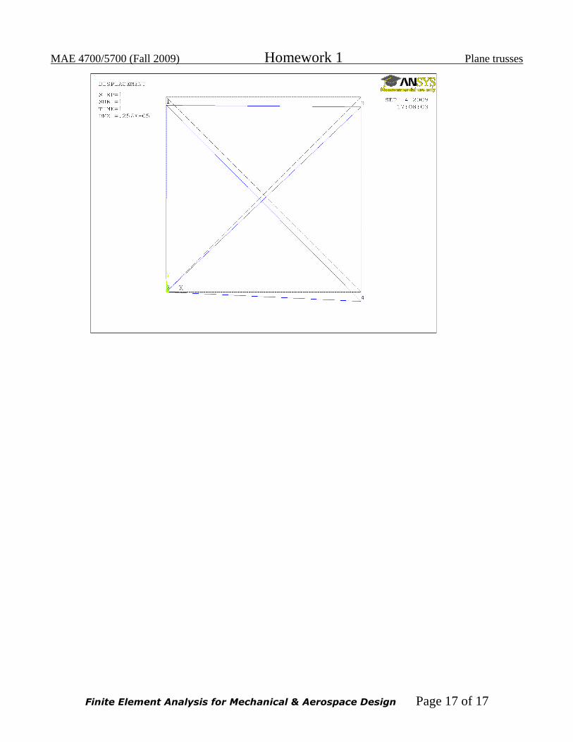
MAE 4700/5700 (Fall 2009) Homework 1 Plane trusses
Finite Element Analysis for Mechanical & Aerospace Design Page 17 of 17