MAE 322 Machine Design Lecture 4 - Mercer...
25
MAE 322 Machine Design Lecture 4 Dr. Hodge Jenkins Mercer University
Transcript of MAE 322 Machine Design Lecture 4 - Mercer...

MAE 322
Machine Design
Lecture 4 Dr. Hodge Jenkins
Mercer University
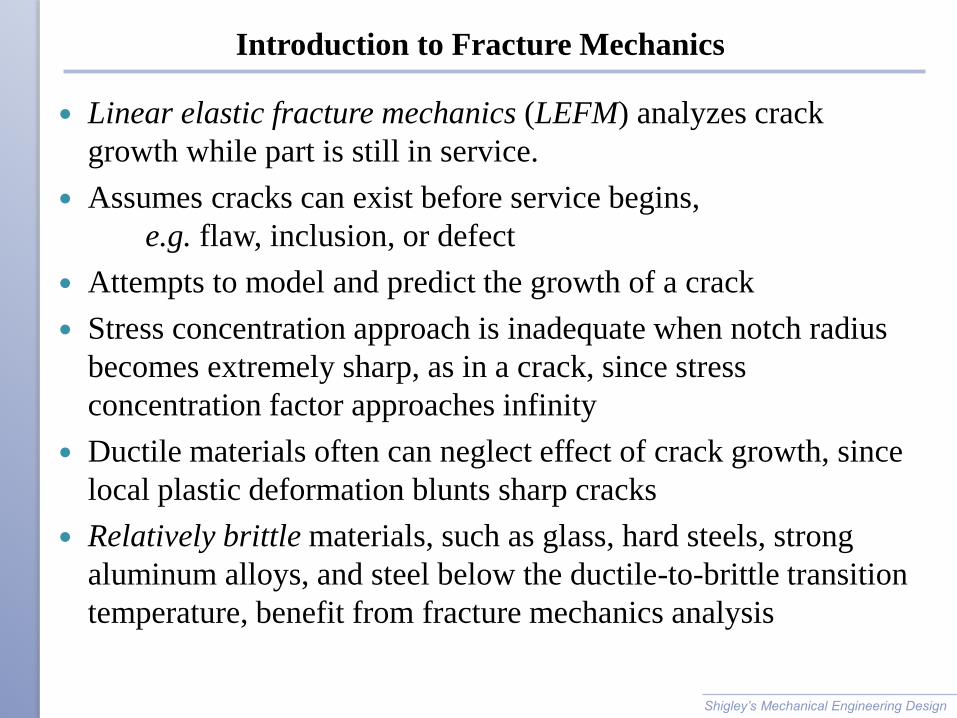
Introduction to Fracture Mechanics
Linear elastic fracture mechanics (LEFM) analyzes crack
growth while part is still in service.
Assumes cracks can exist before service begins,
e.g. flaw, inclusion, or defect
Attempts to model and predict the growth of a crack
Stress concentration approach is inadequate when notch radius
becomes extremely sharp, as in a crack, since stress
concentration factor approaches infinity
Ductile materials often can neglect effect of crack growth, since
local plastic deformation blunts sharp cracks
Relatively brittle materials, such as glass, hard steels, strong
aluminum alloys, and steel below the ductile-to-brittle transition
temperature, benefit from fracture mechanics analysis
Shigley’s Mechanical Engineering Design

Quasi-Static Fracture
A static crack may be stable and not propagate.
Some level of loading can render a crack unstable, causing it to
propagate to fracture.
Shigley’s Mechanical Engineering Design

Quasi-Static Fracture
Foundation work for fracture mechanics
◦ established by Griffith in 1921
Considered infinite plate with an elliptical flaw
Maximum stress occurs at (±a, 0), considering stress
concentration.

Quasi-Static Fracture
Crack growth occurs when energy release rate from applied
loading is greater than rate of energy for crack growth
Shigley’s Mechanical Engineering Design

Crack Modes and the Stress Intensity Factor
Three distinct modes of crack propagation
◦ Mode I: Opening crack mode, due to tensile stress field
◦ Mode II: Sliding mode, due to in-plane shear
◦ Mode III: Tearing mode, due to out-of-plane shear
Combination of modes possible
Opening crack mode is most common
Shigley’s Mechanical Engineering Design
Fig. 5−23

Mode I Crack Model
Stress field on dx dy element at crack tip
Shigley’s Mechanical Engineering Design
Fig. 5−24

Stress Intensity Factor
Common practice to define stress intensity factor
Incorporating KI, stress field equations are
Shigley’s Mechanical Engineering Design

Stress Intensity Modification Factor
Stress intensity factor KI is a function of geometry, size, and
shape of the crack, and type of loading
For various load and geometric configurations, a stress intensity
modification factor b can be incorporated
Tables for b are available in the literature
Figures 5−25 to 5−30 present some common configurations
Shigley’s Mechanical Engineering Design

Stress Intensity Modification Factor
Off-center crack in plate in
longitudinal tension
Solid curves are for crack tip
at A
Dashed curves are for tip at B
Shigley’s Mechanical Engineering Design
Fig. 5−25

Stress Intensity Modification Factor
Plate loaded in longitudinal
tension with crack at edge
For solid curve there are no
constraints to bending
Dashed curve obtained with
bending constraints added
Shigley’s Mechanical Engineering Design
Fig. 5−26

Stress Intensity Modification Factor
Beams of rectangular cross
section having an edge crack
Shigley’s Mechanical Engineering Design
Fig. 5−27

Stress Intensity Modification Factor
Plate in tension containing circular hole with two cracks
Shigley’s Mechanical Engineering Design
Fig. 5−28

Stress Intensity Modification Factor
Cylinder loaded in axial tension having a radial crack of depth a
extending completely around the circumference
Shigley’s Mechanical Engineering Design
Fig. 5−29

Stress Intensity Modification Factor
Cylinder subjected to internal
pressure p, having a radial crack
in the longitudinal direction of
depth a
Shigley’s Mechanical Engineering Design
Fig. 5−30

Fracture Toughness
Crack propagation initiates when the stress intensity factor
reaches a critical value, the critical stress intensity factor KIc
KIc is a material property dependent on material, crack mode,
processing of material, temperature, loading rate, and state of
stress at crack site
Also know as fracture toughness of material
Fracture toughness for plane strain is normally lower than for
plain stress
KIc is typically defined as mode I, plane strain fracture toughness
Shigley’s Mechanical Engineering Design
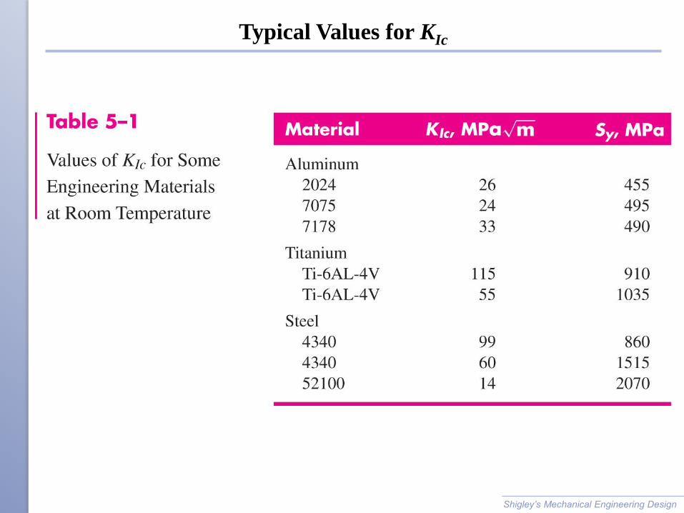
Typical Values for KIc
Shigley’s Mechanical Engineering Design

Brittle Fracture Factor of Safety
Brittle fracture should be considered as a failure mode for
◦ Low-temperature operation, where ductile-to-brittle transition
temperature may be reached
◦ Materials with high ratio of Sy/Su, indicating little ability to
absorb energy in plastic region
A factor of safety for brittle fracture
Shigley’s Mechanical Engineering Design

Example 5−6
Shigley’s Mechanical Engineering Design

Example 5−6 (continued)
Shigley’s Mechanical Engineering Design
Fig. 5−25

Example 5−6 (continued)
Shigley’s Mechanical Engineering Design

Example 5−7
Shigley’s Mechanical Engineering Design

Example 5−7 (continued)
Shigley’s Mechanical Engineering Design

Example 5−7 (continued)
Shigley’s Mechanical Engineering Design Fig. 5−26

Example 5−7 (continued)
Shigley’s Mechanical Engineering Design