MADYMO - CRASH VICTIM SIMULATIONS, - IRCOBI
13
MADYMO - CRASH VICTIM SIMULATIONS, A COHPUTORISED RESEARCH AND DESIGN TOOL% by J. Maltha, J. Wismans Research Institute for Raad Vehicles TNO, DELFT - NETHERLANDS Abstract MADYMO is a compact general purpose computer program package for two- or three- dimensional Crash Victim Simulations. The program predicts the kinematic and dynamic behaviour of the victim during the crash, based on data of the victim, environment, safety devices and crash conditions. The package differs from most of the existing CVS programs by its flexibility in choice of number of linkages and number of elements in each linkage. Great flexibility in the modelling of force interactions between elements and environment is assured by the fact that user-defined submodels can readily be incorporated. The program is used in basic biomechanical crash research as well as the development and optimisation of crash safety devices such as seat belts and child seats. This paper briefly discusses the theoretical basis and the use of MADYMO, with some examples of applications. INTRODUCTION In the field of automotive safety research, simulation of crashes to study the effects on the human body is vital in order to evaluate and improve crash safety devices and occupant environment. Most of this work is done by way of experiments, using instrumented dummies, cadavers, and occasionally animals or volunteers. In the sixties, fast digital computers together with advanced mathematical techniques led to a new method i.e. simulation with mathematical models. These models have the advantage that a great number of simulation results can be % This paper is also presented at the ISATA 80 symposium, Torino, Italy, September 1980. 1
Transcript of MADYMO - CRASH VICTIM SIMULATIONS, - IRCOBI

MADYMO - CRASH VICTIM SIMULATIONS,
A COHPUTORISED RESEARCH AND DESIGN TOOL%
by
J. Maltha, J. Wismans
Research Institute for Raad Vehicles TNO, DELFT - NETHERLANDS
Abstract
MADYMO is a compact general purpose computer program package for two- or three
dimensional Crash Victim Simulations. The program predicts the kinematic and
dynamic behaviour of the victim during the crash, based on data of the victim,
environment, safety devices and crash conditions. The package differs from most
of the existing CVS programs by its flexibility in choice of number of linkages
and number of elements in each linkage. Great flexibility in the modelling of
force interactions between elements and environment is assured by the f act that
user-defined submodels can readily be incorporated. The program is used in
basic biomechanical crash research as well as the development and optimisation
of crash safety devices such as seat belts and child seats. This paper briefly
discusses the theoretical basis and the use of MADYMO, with some examples of
applications.
INTRODUCTION
In the field of automotive safety research, simulation of crashes to study the
effects on the human body is vital in order to evaluate and improve crash
safety devices and occupant environment. Most of this work is done by way of
experiments, using instrumented dummies, cadavers, and occasionally animals or
volunteers.
In the sixties, fast digital computers together with advanced mathematical
techniques led to a new method i.e. simulation with mathematical models. These
models have the advantage that a great number of simulation results can be
% This paper is also presented at the ISATA 80 symposium, Torino, Italy, September 1980.
1

obtained easily, for there is no practical limit on the number of sensors and
there are no other measurement problems as occur with experiments. Based on the
complete reproducibility of computer simulations, sensitivity studies to estab
lish the relative importance of system parameters can be easily carried out.
Hathematical models in conjunction with experiments can effectively reduce the
number of tests with cadavers, animals or volunteers which are sometimes con
troversial.
This paper describes the MADYMO general purpose computer program package for
Crash Victim Simulations.
EXISTING CRASH VICTIM SIMULATION MODELS
Mathematical models to simulate automobile crash victims have been developed
during the past seventeen years. Such models are either 2- or 3-dimensional
with a number of mass-carrying elements representing the human body ranging
from 3 up to 15 (variable for the CAL-30-CVS model).
In general, models have provisions to simulate realistic joint characteristics
by elastic springs, viscous damping, coulomb friction and joint stops. The ex
terior body geometry is primarily presented by contact-sensing ellipses and the
environment of the victim by sections of lines or planes. Resulting contact
forces are calculated from tabular force-deformation curves together with pro
visions for viscous damping and coulomb friction. Restraint belt forces are
calculated by simple or more sophisticated submodels.
The crash energy input is the acceleration time histories for almost all models.
A detailed review and comparisons of existing models are given by King 111, Robbins 121 and Huston j 3 j .
The MADYMO Crash Victim Simulation program package offers a choice of either 2-or 3-dimensional simulation and complete freedom of selection of the number of
linkage systems, each with a variable number of elements. In addition, the
package is arranged to be easy to use and compact in program size and memory
storage needs, and therefore intermediate sized computers can be used for most
simulations.
THEORETICAL BASIS OF MADYMO
Most existing computer models used to study the highly variable gross motion of
the human body during a car crash are based on tree-structured linkages of
rigid elements connected by joints. The motion of these systems is a result of
2

externally applied forces, force interactions between elements and environment
and of torques in the joints. Those forces and torques during the simulation
are calculated by submodels using geometric and kinematic data in the system.
These submodels are called "force interaction models" and will be described in
the next chapter.
In order to perform a time-history simulation of the motion it is necessary to
derive the equations of motion for the systems. These equations calculate the
accelerations of the elements for each time-point using the external forces and
torques from the force interaction models. The accelerations are then used for
an integration procedure to predict the positions and velocities of the elements
for the next time-point. The equations of motion are non-linear and havc timc
dependent coefficients due to the widely varying geometry of the systems.
Basically, there are two methods of deriving the equations of motion for sys
tems of rigid bodies connected by pinned or ball and socket joints. One is the
Newton-Euler and the other is the Lagrange method. Other authors advocate a
combination of these methods known as Lagrange's form of d 'Alembert's principle
14, s I . For MADYMO the Lagrange method is used to establish a formalism f or computer
generation of the equations of motion. The advantage of this method is that the
exact number of governing equations is directly obtained, without any need to
eliminate constraint forces in the joints.
The position of each element with respect to time is expressed in an arbitrarily
chosen, recta�gular, absolute reference frame. A local rectangular frame with
its origin in one of the joints is rigidly connected to each element. The
angular orientation of each element with respect to the absolute reference frame
is defined by three independent Bryant angles 161 or a single rotation angle
for 2-dimensional simulations. These rotations together with rectangular coor
dinates in the absolute reference frame of one selected reference joint of the
linkage form the generalised coordinates.
The mass distribution of a rigid element is represented by an arbitrarily lo
cated concentrated mass and by 3 principal moments of rotational inertia. For
each element an arbitrarily number of joints can be defined representing the
connections with adjacent elements (fig. 1).
3

z. 1
fig. 1 rigid element
m = concentrated mass
I X
I y I z
= {principal moments of rotational inertia
=
g vector defining centre of gravity
s vector(s) defining the joint(.s) with adjacement element (s)
Lagrange's equation ( 1) is applied to a single chain of n successive numbered
elements:
( 1)
where: T total system kinetic energy
qk k-th generalised coordinate
Qk = k-th generalised force
Splicing and regrouping of these equations, together with the introduction of
partition matrices to break down the local coordinate systems transformations,
leads to the final form (2) :
..
Sq
where: S = symmetrical system matrix; it contains mass, inertia
and dimensions;
q column matrix with the elements of the generalised
accelerations qk(k=1, 3(n+1));
r = column matrix with the generalised forces due to s velocity effects (pseudo forces: centrifugal and
coriolis);
rk = column matrix with the generalised forces due to
external forces and torques on the system.
(2)
4
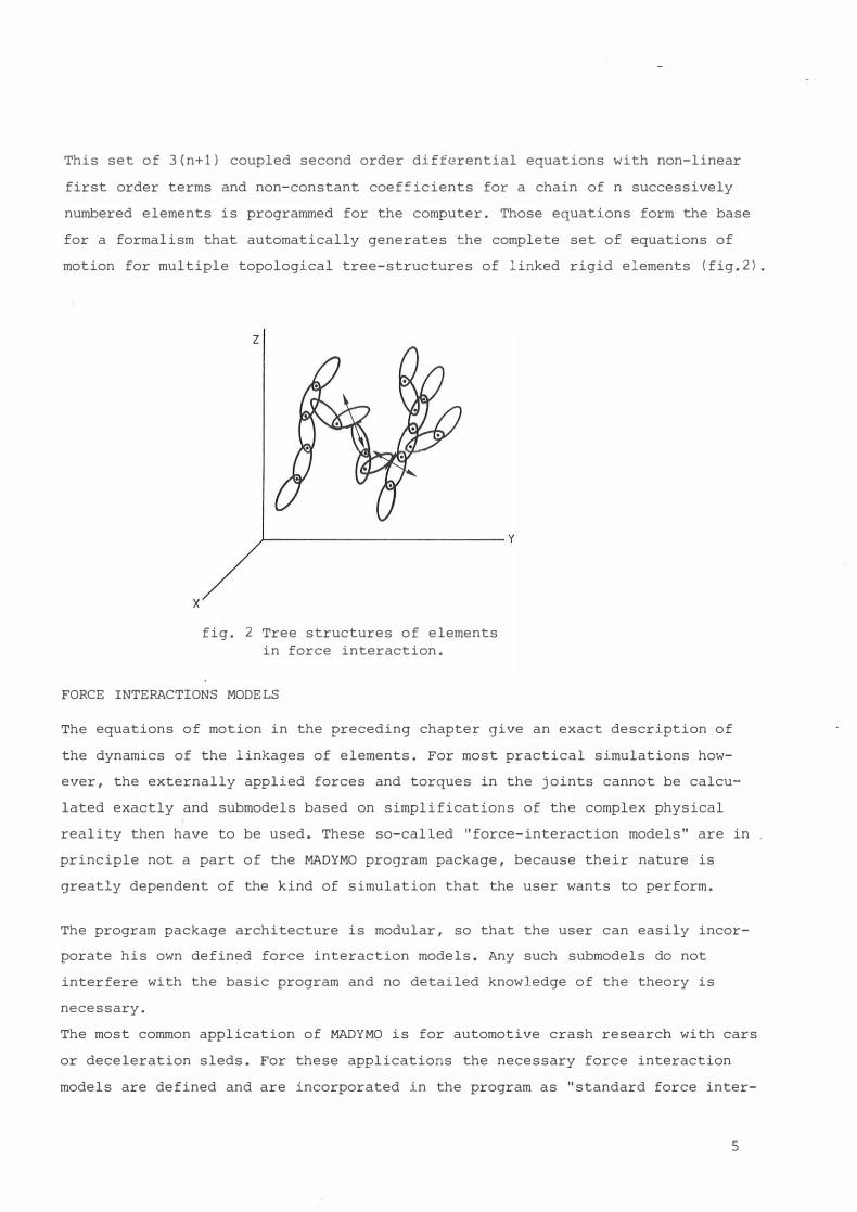
This set of 3(n+1) coupled second order differential equations with non-linear
first order terms and non-constant coeff icients for a chain of n successively
numbered elements is programmed for the computer. Those equations form the base
for a formalism that automatically generates the complete set of equations of
motion for multiple topological tree-structures of linked rigid elements (fig.2).
X
z
fig. 2 Tree structures of elements
in force interaction.
FORCE INTERACTIONS MODELS
The equations of motion in the preceding chapte� give an exact description of
the dynamics of the linkages of elements. For most practical simulations how
ever, the externally applied forces and torques in the joints cannot be calcu
lated exactly and submodels based on simplifications of the complex physical
reality then have to be used. These so-called "force-interaction models" are in
principle not a part of the MADYMO program package, because their nature is
greatly dependent of the kind of simulation that the user wants to perform.
The program package architecture is modular, so that the user can easily incor
porate his own defined force interaction models. Any such submodels do not
interfere with the basic program and no detailed knowledge of the theory is
necessary.
The most common application of MADYMO is for automotive crash research with cars
or deceleration sleds. For these applications the necessary force interaction
models are defined and are incorporated in the program as "standard force inter-
5
action models" and are described below.
1. Joint torque model
This submodel calculates the resistive torques in the joints between two con
nected elements. For each relative rotation (one for 2-dimensional and three
for 3-dimensional) a separate torque is defined. These torques may consist of
elastic, viscous damping and coulomb friction components. The elastic torque
is dependent on a tabular torque-relative angle function which represents any
continuous curve. This curve may also be used to model "soft elastic" joint
stops by giving the curve a steep slope at the end of the joint range of motion.
2 . Acceleration forces model
This model calculates accelerative (decelerative) forces on the centre of
gravity of each element. These forces are dependent on tabular acceleration
time functions representing the continuous acceleration history curves.
3. Contact forces model
This submodel calculates forces for contacts detected during the simulation
between an ellipsoid and a plane. Each ellipsoid and each plane may be connected
to any element of any system or to the laboratory fixed absolute reference
frame.
The calculated force may consist of elastic, viscous damping and coulomb fric
tion components. The elastic force is dependent on a tabular force-perpendicular
penetration function representing any continuous curve.
4. Belt forces model
This submodel calculates belt forces for belts between two elements or belts
between an element and any location in the fixed absolute reference frame.
The belt force is dependent on a tabular force-relative elongation function
representing any continuous curve. This routine also has an option for initial
belt slack or pretension.
MADYMO CRASH VICTIM SIMULATION PROGRAM PACKAGE
The MADYMO package is based on the FORTRAN source code to rnake adaptions easy.
All tables with input and simulation parameters are contained in common area's
for shared use of those by MADYHO and the user-defined routines. The package
6

contains a standard output print option of all input and s imulation data. For
most si�ulations the user is interested in only a small portion of the output
data , which can be obtained by a simple user-defined subroutine for printing
these data . This same routine may be used to produce datafi les with relevant
information for user-written, post-processing plotprograms to produce stick
figures for the kinematics and graphs of the dynamics.
The size of the standard program fi les of MADYMO version 1 are 1450 cards for
2-dimensional and 2 200 cards for 3-dimensional s imulations (these numbers in
clude the cards with explanatory comment lines) . The memory storage needs and
the computer run t imes are dependent on the specific simulation data , such as
number of mode lled e lements , number of contacts a llowed etc.
In principle , MADYMO can be used for other problems in the fie ld of dynamics of
systems of rigid bodies , because the package readi ly a l lows a l l kind of sub
models for force calculation to be incorporated.
VALIDATION OF MODELS
In genera l , the results of s imulations with mathematical models must be compared
with physical reality.
For some simulations a theoretical solution to the problem exists , examples
being vibrating spring mass systems and swinging pendulums. In those cases the
model results can be directly compared with the theoretical solution. This pro
cess can be denominated as an ANALYTICAL VALIDATION of the model and may be
used for a check of correctness of algor ithms and programming. For most simula
t ions , however , no theoretical solution exists and validation has to be based
on comparison ·with experimental results. The dicision that the model predictions
corre late acceptably with observed facts can be denominated as EXPERIMENTAL
VALIDATION.
In practice, this means that a subset out of the model results must be se lected
and a criterion must be found to determine whether or not the correlation with
the experimental results is acceptable. This problem of establishing a method
for validation has not yet been solved complete l y , so the only way to approach
this problem now is to follow common practice and good engineering judgement 171.
7
HOW TO USE THE PROGRAM PACKAGE
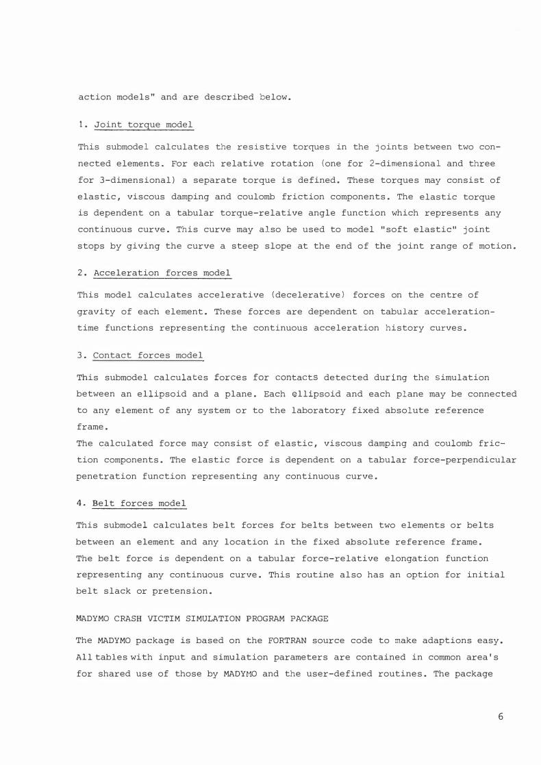
The use of the MADYMO program package is illustrated with an example of a
simplified planer simulation of a car crash with a child dummy sitting in a
child restraint seat (see fig. 3).
fig. 3 Simulation example
A first step towards a simulation is to make a set-up drawing for definition of
relevant elements, geometry, contacts, belts, reference frames etc. (see fig.4).
The geometrical values from the drawing together with selected data for the
masses, location of centres of gravity, moments of inertia, joint properties,
contact properties, belt properties and car deceleration pulse are grouped into
tables to form the input data set. These data may be obtained from measurements
on the dummy, child seat, car seat belts etc. or selected from literature and
estimations.
For the simulation defined by this input data set, the selected 2 - or 3-dimen
sional standard program file is exactly dimensioned to obtain minimum program
memory storage requirements. This dimensioning is simply effected through
the user's local computer editing facilities by replacing symbolic array
declarations with the relevant numbers.
8

z child : system 1 chl/dseat · syslem 2 car seal : absolute reference
lrarr.e
fig. 4 Set-up drawing for mathemat ical simulation
Finally, the program f i le is completed by an additional user-written subroutine
for printing a table with time functions of some selected variables (fig. 5) •
TIME LAPBELT CONTACT 2 RES. HEAD ACC. HEAD EXC. (SEC) FORCE(N) FORCE(N) ( M/ S**2) ( M)
0.000 0. 0. 0. 0.000 .002 0. 0. o . o.ooo • 004 0 . 0. 0. 0.000 . 006 0. 0. 0 . 0.000 • 008 0. 0. 0. 0.000 . 010 0. 0. o . 0.000 . 012 0. 1. 40. .000 • 014 o. 5. 80 . .000 • 016 1 • 12. 11 8 . . 00 1 • 018 3. 21. 158. .002 .020 7. 34. 198. .003 . 022 12 • 49. 19 5. .006
• 024 1 9. 66 . 197. .009 • 026 29. 83 • 19 4. .013 .028 38-. 105. 191 . .018
·2?0 47. 18 3. 190. .023
fig. 5 Output table with time functions of some user-selected var iables
9

This routine may also be used to produce files with time functions o= so�e
coordinates, forces, accelerations etc. which are used as input for user-made,
post-processing programs to plot simulation, kinematics and dynamics (fig. 6) .
. 000:'.; o�co or.oo l;rre(sl
.0600 oa::o t;IT'e(S)
fig. 6 Example of user-made plots
The optional standard printed output of the complete simulation data is in
practice only used for diagnosis of errors due to mistakes in the input data
or poor modelling assumptions.
EXAMPLES OF APPLICATIONS
The versatility of the MADYMO program package for a wide variation of applica
tions is shown by a selection of plotfigures showing kinematics of different
simulations (fig. 7 , 8 , 9 , 10, 11, 12).
fig. 7 Pedestrian-car
collision
fig. 8 Baby carrycot
on rear seat
10

fig. 9 Child restraint
seat evaluation
fig. 1 1 Mathematical reconstruction of frontal collision
fig. 10 Design study on
dynamic-acting child
restraint seat
fig. 12 Deceleration sled
test for belt
approval
MADYMO was used successfully in a combined study of experimental and mathema
tical evaluation of a child restraint system. This study showed that the
mathematical model of the child gives a better representation of cadaver kine
matics than a dummy does lsl. The package is now used for mathematical recon
struction of � real frontal collision 19 1 and for a computer-aided design study
of a dynamic-acting, child restraint seat 1101. STANDARD DATA SETS
Mathematical CVS models are potentially a powerful tool for research. and design
studies. The widespread use of this tool has been held back because CVS models
are not always easy to use and sometimes have complex input data structures. In
addition, there is a lack of reliable input parameters. Some of the input data
are easily obtainable, e.g. geometrical values, but others, like dynamical joint
and contact properties, must be established by complicated measurements.
1 1

A great deal of ef fort is now being invested in MADYMO to standardize input
data sets for representation of existing car crash dumrnies . These could con
s iderably reduce the set-up costs and time spent on a particular simulation .
The user then s imply selects the data set and only provides additional data
for the environment , restraint systems and crash conditions .
In a way thi s can raise mathematical modelling to a level comparable with
experimental crash research. For realiable data sets of dumrnie s , cadavers and
real victim , cooperation between laboratories using the CVS models , and basic
researchers working on anthropometric data banks , is e s sential .
CONCLUSIONS
- MADYMO i s a useful tool in crash research projects and design optimization .
- MADYMO offers the user a choice of either 2- or 3-dimens ional s imulation of
multiple tree-structured linkages of rigid elements . Each tree-structure may
have any number of elements .
- The program package readily allows user-defined submodels for force inter
action calculation to be incorporated.
- Mathematical simulations can be used for sensitivity studies of systems
parameters and reduce the number of necessary exper iments .
- Standard input data sets can reduce the set-up costs and time for a simula
tion considerably .
ACKNOWLEDGEMENTS
MADYMO has been developed at the Research Institute for Raad Vehicles TNO ,
Delft, The Netherlands in collaboration with the Netherlands Institute for Raad
Safety Research , SWOV. This i s a s ix-year program sponsored by the Dutch
Government .
REFERENCES
1 . King , A . I . and Chou, c.c. , "Mathematical modelling , simulation and experi
mental testing of b iomechanical system crash response" , J . Biomechanics ,
1976 , Val . 9.
2. Robbins, D . H . , "Simulation of human body response to crash loads" , In
Shock and vibration computer programs . Pp . 365 . 380 , 1975 .
12
3. Husten, R.L., "A summary of 3-dimens ional , gross-mot ion , crash victim
simulations".
4. Roberson, R. E. , "Adaption of a general multi-body formal i sm to dynamic
simulation of terrestrial vehicles", Vehicle Systems Dynamic s , 1977, Vol. 6 .
5 . Husten , R.L., Hessel, R.E. and Winget , J . M . , "Dynamics of a crash victim
a finite segment model", AIAA Journal , 1976 , Vol. 14.
6. Wittenburg, J. , "Dynamics of systems of rigid bodies" , B.G . Teubner ,
Stuttgart, 1977 .
7. Robbins, D.H. , Bennet, R.O. and Becker , J. M., "Val idation of Human Body
Model l ing for dynamic s imulation", International Automotive Engineering
Congress and Exposit ion, Detroit, 1977, SAE nr. 770058 .
8. Wismans, J . S.H. M., Maltha, J., Melvin, J.W. and Stalnaker, R.L. , "Child
Restraint evaluation by experimental and mathematical s imulation" , Twenty
third Stapp car crash Conference, San D iego, 1979, SAE nr. 7919 17.
9 . Wismans , J.S.H.r1. , Cesari, D. and Maltha, J., "Reconstruction of a real
frontal col l i s ion with mathemat ical models in compar ison with a cadaver
and a dummy", to be presented at the IRCOBY Conference, Birmingham, 1980 .
10. Stalnaker, R.L. and Maltha, J. , "MADYMO used for computer-aided des ign of
a dynamic..::acting ,· child restraint seat" , to be presented at I RCOBY Conference
Birmingham , 1980.
13
•.