MADE IN User’s Guide - OMEGA Engineering | … · DTG-RTD100 SERIES Digital Temperature Gauge...
48
DTG-RTD100 SERIES Digital Temperature Gauge MADE IN e-mail: [email protected] For latest product manuals: omegamanual.info Shop online at omega.com ® User’s Guide
Transcript of MADE IN User’s Guide - OMEGA Engineering | … · DTG-RTD100 SERIES Digital Temperature Gauge...

DTG-RTD100 SERIESDigital Temperature Gauge
MADE IN
e-mail: [email protected] latest product manuals:
omegamanual.info
Shop online atomega.com ®
User’s Guide

Servicing North America:U.S.A.: Omega Engineering, Inc., One Omega Drive, P.O. Box 4047ISO 9001 Certified Stamford, CT 06907-0047 USA
Toll Free: 1-800-826-6342 TEL: (203) 359-1660FAX: (203) 359-7700 e-mail: [email protected]
Canada: 976 BerarLaval (Quebec), H7L 5A1, CanadaToll-Free: 1-800-826-6342 TEL: (514) 856-6928FAX: (514) 856-6886 e-mail: [email protected]
For immediate technical or application assistance:U.S.A. and Canada: Sales Service: 1-800-826-6342/1-800-TC-OMEGA®
Customer Service: 1-800-622-2378/1-800-622-BEST®
Engineering Service: 1-800-872-9436/1-800-USA-WHEN®
Mexico/ TEL: 001 (203) 359-1660 FAX: 001 (203) 359-7700Latin America: e-mail: [email protected]
Servicing Asia:China:: 1698 Yi Shan Road, Unit 102
Min Hang DistrictShanghai, China 201103 P.R.C.Hotline: 800 819 0559/400 619 0559e-mail: [email protected]
Servicing Europe:Benelux: Toll-Free: 0800 099 3344 TEL: +31 20 347 21 21
FAX: +31 20 643 46 43 e-mail: [email protected]
Czech Republic: Frystatska 184733 01 Karviná, Czech RepublicTEL: +420-59-6311899 FAX: +420-59-6311114e-mail: [email protected]
France: Toll-Free: 0800 541 038 TEL: 01 57 32 48 17FAX: 01 57 32 48 18 e-mail: [email protected]
Germany/ Austria: Daimlerstrasse 26D-75392 Deckenpfronn, GermanyToll-Free: 0800 8266342 TEL: +49 (0) 7056 9398-0FAX: +49 (0) 7056 9398-29 e-mail: [email protected]
United Kingdom: OMEGA Engineering Ltd.ISO 9001 Certified One Omega Drive, River Bend Technology Centre, Northbank
Irlam, Manchester M44 5BD United KingdomToll-Free: 0800-488-488 TEL: +44 (0) 161 777-6611FAX: +44 (0) 161 777-6622 e-mail: [email protected]
OMEGAnet® Online Service Internet e-mailomega.com [email protected]
It is the policy of OMEGA Engineering, Inc. to comply with all worldwide safety and EMC/EMIregulations that apply. OMEGA is constantly pursuing certification of its products to the European NewApproach Directives. OMEGA will add the CE mark to every appropriate device upon certification.The information contained in this document is believed to be correct, but OMEGA accepts no liability for anyerrors it contains, and reserves the right to alter specifications without notice.WARNING: These products are not designed for use in, and should not be used for, human applications.

i
DTG-RTD100Digital Temperature Gauge
TABLE OFCONTENTS
PageSection 1 - Introduction ....................................................................... 1-1
1.1 Precautions ................................................................................................ 1-11.2 Statement on FCC and CE Marking........................................................ 1-21.3 General Description .................................................................................. 1-2
Section 2 - Hardware .......................................................................... 2-12.1 Unpacking and Inspection ...................................................................... 2-12.2 Included Items .......................................................................................... 2-1
Section 3 - Setup & Configuration ........................................................ 3-13.1 Getting Started .......................................................................................... 3-13.2 Software Utility ......................................................................................... 3-13.3 Software Installation ................................................................................ 3-13.4 Configuration ............................................................................................ 3-4
Section 4 - Installation, Mounting & Wiring .......................................... 4-14.1 Installation ................................................................................................. 4-14.2 Ambient Temperature .............................................................................. 4-14.3 General Meter Dimensions ...................................................................... 4-14.4 Battery Installation/Replacement .......................................................... 4-24.5 Mounting ................................................................................................... 4-34.6 Wiring (Sensor, Power, Analog Output) ................................................ 4-4
Section 5 - Display Features & Meter Operation .................................... 5-15.1 Display Features ....................................................................................... 5-15.2 Keypad Operation .................................................................................... 5-1
Section 6 - Optional Wireless Transmitter Operation ............................ 6-16.1 Introduction ............................................................................................... 6-16.2 RF Communication Basics ....................................................................... 6-16.3 Basic System Overview ............................................................................ 6-16.4 Transmit Rate vs. Battery Life ................................................................. 6-36.5 Wireless Transmitter Setup ...................................................................... 6-6
Section 7 - DTG-RTD100 Design for CE Conformity ................................ 7-17.1 DTG-RTD100 Analog Output Grounding ............................................. 7-17.2 Ferrite Cores .............................................................................................. 7-2
Section 8 - Service and Calibration ....................................................... 8-1
Section 9 - Specifications ..................................................................... 9-19.1 General .................................................................................................... 9-19.2 Wireless Option ......................................................................................... 9-1
Section 10 - Approvals, Regulatory Compliance ................................. 10-1

ii
DTG-RTD100Digital Temperature Gauge
LIST OFFIGURES
List of FiguresSection Figure Description ............................................................... Page
Section 1.1 1-1 Rear Label Standard ..................................................1-1
Section 1-1 1-2 Rear Label Wireless ................................................... 1-1
Section 3.3 3-1 Software - Welcome Screen ...................................... 3-1
Section 3.3 3-2 Software - Installation Options Screen.................... 3-2
Section 3.3 3-3 Software - Select Installation Folder Screen ........... 3-2
Section 3.3 3-4 Software - License Agreement Screen ..................... 3-3
Section 3.3 3-5 Software - Installation Complete Screen................. 3-3
Section 3.4 3-6 Lid/Cover Removal ................................................. 3-4
Section 3.4 3-7 USB Programming Cable .......................................... 3-5
Section 3.4 3-8 USB Connector Location .......................................... 3-5
Section 3.4 3-9 Launch Setup Utility Screen ..................................... 3-5
Section 3.4 3-10 Utility Program - Welcome Screen........................... 3-6
Section 3.4 3-11 Utility Program - Connect To Digital Gauge Screen .3-6
Section 3.4 3-12 Utility Program - Verify Connections Screen ......... 3-7
Section 3.4 3-13 Utility Program - Establish Link Screen.................. 3-7
Section 3.4 3-14 Utility Program - Choose Options Screen .............. 3-8
Section 3.4 3-15 Analog Output Options ......................................... 3-11
Section 3.4 3-16 Calibrations Options Screen - Skip Calibration Option .......................................... 3-12
Section 3.4 3-17 Calibrations Options Screen - Skip To Next Operation........................................... 3-13
Section 3.4 3-18 Send Settings To Digital Gauge Screen-Finish Option ................................................................ 3-13
Section 4.3 4-1 General Meter Dimensions ...................................... 4-1
Section 4.4 4-2 Battery Installation/Replacement .......................... 4-2
Section 4.5 4-3 Mounting Bracket Accessory, Model DTG-RTD100-MB ................................................ 4-3
Section 4.6 4-4 Wiring - Terminal Block Location ........................... 4-4
Section 4.6 4-5 Wiring - Temperature Sensor ................................... 4-4
Section 4.6 4-6 Wiring - M12 Connector ........................................... 4-4
Section 4.6 4-7 Wiring - Power Supply ............................................. 4-5
Section 4.6 4-8 Wiring - Analog Output ........................................... 4-5
Section 4.6 4-9 Wiring - Alarm ........................................................... 4-6
Section 5.1 5-1 Display Features ........................................................ 5-1
Section 5.2 5-2 Keypad Operation ..................................................... 5-1
Section 5.2 5-3 Magnetic Stylus ......................................................... 5-2
Section 5.2 5-4 Menu Button Operation .................................... 5-3, 5-4
Section 5.2 5-5 Front Keypad Set Button .......................................... 5-5
Section 6.3 6-1 Fresnel Zone ............................................................... 6-1

List of Figures continuedSection 6.4 Table 1 DTG-RTD100 Battery Life - Standard Mode ..........6-3
Section 6.4 Table 2 DTG-RTD100-W Battery Life - Wireless Mode(2 x 4.8Ah Batteries) ....................................................6-4
Section 6.4 Table 3 DTG-RTD100-W Battery Life - Wireless Mode(2 x 8.5Ah Batteries) ....................................................6-5
Figure
Section 7.1 7-1 Analog Output Wiring Example ............................. 7-1
Section 7.1 7-2 Analog Output Grounding Example ...................... 7-1
Section 7.2 7-3 Ferrite Core .................................................................7-1
Section 7.2 7-4 Ferrite Core Installation ............................................ 7-2
iii
DTG-RTD100Digital Temperature Gauge
LIST OFFIGURES

NOTES:
DTG-RTD100 Digital Temperature Gauge
iv
Section 1 - IntroductionPlease read this manual completely before installing and operating yourinstrument. It’s important to read and follow all notes, cautions, warnings andsafety precautions before setting up, installing and operating this unit.
1.1 Precautions• This device has not been designed, tested or approved for use in any medical
or nuclear applications.
• Never operate this device in flammable or explosive environments.
• Never operate with a power source other than the one recommended in thismanual.
• Never operate this device outside of the recommended use outlined in thismanual.
For models with wireless transmitter option
• No co-location with other radio transmitters is allowed. By definition, co-location is when another radio device or it’s antenna is located within 20 cmof your unit and can transmit simultaneously with your unit.
• Never install a wireless unit within 20 cm or less from each other.
• Never install and/or continuously operate your wireless unit closer than 20 cmto nearby persons.
• Never use your wireless unit as a portable device. Your unit has been designedto be operated in a permanent installation only.
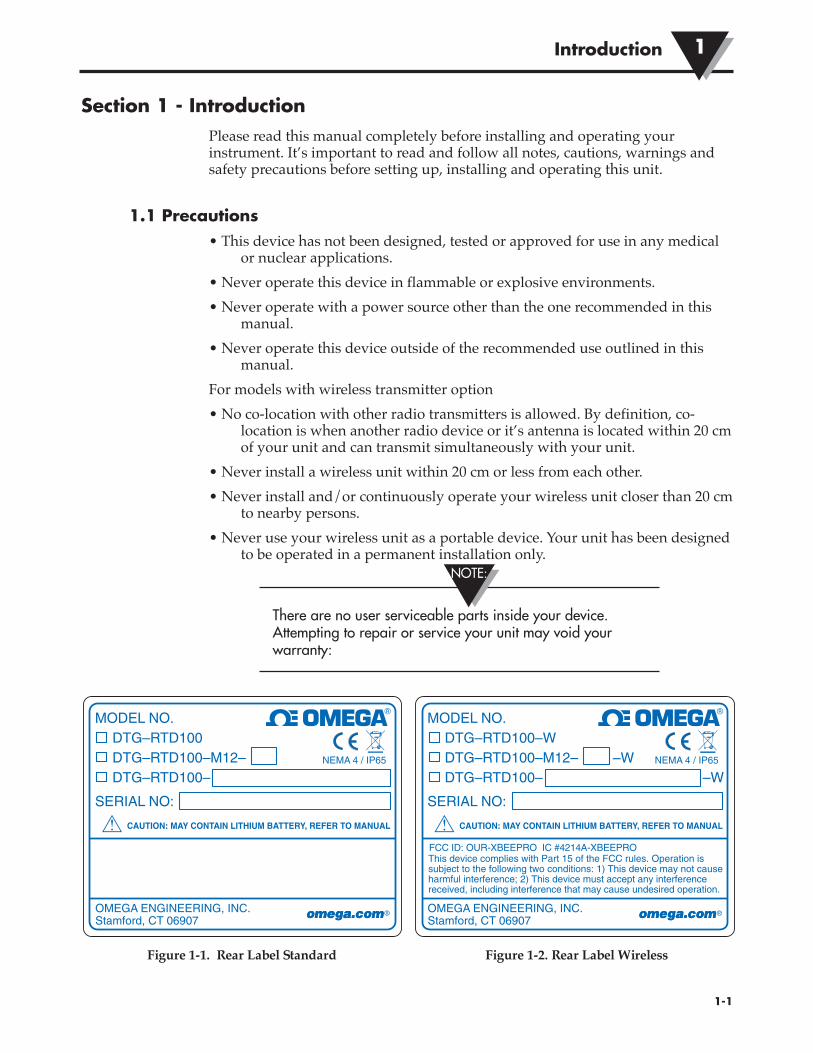
There are no user serviceable parts inside your device.Attempting to repair or service your unit may void yourwarranty:
Figure 1-1. Rear Label Standard Figure 1-2. Rear Label Wireless
1-1
Introduction 1
NOTE:
MODEL NO. DTG–RTD100 DTG–RTD100–M12– DTG–RTD100–
SERIAL NO:
CAUTION: MAY CONTAIN LITHIUM BATTERY, REFER TO MANUAL
OMEGA ENGINEERING, INC. Stamford, CT 06907
!
NEMA 4 / IP65
®
MODEL NO. DTG–RTD100–W DTG–RTD100–M12– DTG–RTD100–
SERIAL NO:
CAUTION: MAY CONTAIN LITHIUM BATTERY, REFER TO MANUAL
OMEGA ENGINEERING, INC. Stamford, CT 06907
This device complies with Part 15 of the FCC rules. Operation is subject to the following two conditions: 1) This device may not cause harmful interference; 2) This device must accept any interference received, including interference that may cause undesired operation.
FCC ID: OUR-XBEEPRO IC #4214A-XBEEPRO
!
NEMA 4 / IP65–W–W
®

1.2 Statement on FCC and CE MarkingFCC Marking
FCC ID: OUR-XBEEPRO IC #4214A-XBEEPRO
This device complies with Part 15 of the FCC rules. Operation is subject to thefollowing two conditions: 1.) This device may not cause harmful interference. 2.) This device must accept any interference received, including interference thatmay cause undesired operation.
CE Marking
It is the policy of OMEGA to comply with all worldwide safety and EMI/EMCregulations that apply. OMEGA is constantly pursuing certification of itsproducts to the European New Approach Directives. OMEGA will add the CEmark to every appropriate device upon certification.
1.3 General DescriptionOMEGA’s new DTG-RTD100 Thermometer Series features a rugged 316 stainlesssteel enclosure that is designed specifically for wash-down, sanitary and marineapplications. The large backlit LCD display incorporates both large 25 mm (1")digits and a 25 segment bar graph that makes reading at distances up to 10.7 m(35') easy. Models are available with or without integral industrial or sanitarytemperature sensors. Standard features include: internal battery or external DCpower supply operation, analog output and user programmable alarms. Theoptional built-in wireless transmitter allows for remote monitoring, chartrecording and data logging. A variety of user configurable options and settingsinclude: update rate, dampening, units, backlight level, alarm setting, analogoutput scaling and auto-power-off.
Introduction1
1-2

Section 2 – HardwareIt is important that you read this manual completely and follow all safetyprecautions before operating this instrument.
2.1 Unpacking & InspectionRemove the packing list and verify that you have received all your equipment. Ifyou have any questions about the shipment, please call our Customer ServiceDepartment at 1-800-622-2378 or 203-359-1660. We can also be reached on theInternet at www.omega.com, e-mail: [email protected]. When you receive theshipment, inspect the container and equipment for any signs of damage. Noteany evidence of rough handling in transit. Immediately report any damage tothe shipping agent.
The carrier will not honor any damage claims unless allshipping material is saved for inspection. After examiningand removing contents, save packing material and carton inthe event reshipment is necessary.
2.2 Included ItemsThe following items are supplied in the box.
• 1 DTG-RTD100 Thermometer Assembly
• 1 User’s Guide
• 1 USB Programming Cable
• 1 Setup Utility Software Disk
• 2 Ferrite Cores
• 1 Analog Output Grounding Cable
2-1
Hardware 2
NOTE:

Section 3 – Setup & Configuration3.1 Getting Started
This section outlines how to setup and configure your DTG-RTD100Thermometer before installation and use. All configuration settings are set andsaved into your meter by connecting the included USB programming cable andrunning the software utility that was included with your unit on your computer.
3.2 Software UtilityYour computer should meet the following minimum requirements:
• Pentium Class processor
• Hard Drive Space: 210 meg
• Ram: 256 meg or higher
• 1 Available USB Port
• 1 CD-ROM Drive
• Windows 2000, XP, Vista (32bit) Operating System or Windows 7.
3.3 Software InstallationInsert the software CD that was included with your unit into the CD-ROM driveon your PC. Your system should begin the installation process automatically.
Figure 3-1. Software - Welcome Screen
This welcome screen will be visible on your computer. To continue installing theprogram click the “Next >” button.
3-1
Setup & Configuration3

Figure 3-2. Software - Install Options Screen
From this screen you select if you want the program icons to be placed on yourdesktop and to automatically install the USB drivers. To continue with installingthe program click the “Next >” button.
Figure 3-3. Select Installation Folder Screen
From this screen you select the folder were you want the program files installedon your PC. The default setting will install the software under your “Program”folders in a new folder named “Omega” To continue with installing the programclick the “Next >” button.
Setup & Configuration 3
3-2

Figure 3-4. Software - License Agreement Screen
From this screen you must select “Agree” to continue installing your program.After making your selection click the “Next >” button. The setup wizard willnow complete the process and install the software.
Figure 3-5. Software - Installation Complete Screen
Congratulations! You have just successfully installed the DG Setup UtilityProgram on your PC. To end installing the program and close the setup wizardclick the “Close” Button
Setup & Configuration3
3-3

3.4 ConfigurationLid/ Cover Removal
To access the USB programming connector on your meter, the enclosurelid/cover must be removed. Four screws must be removed. Be careful to not loseor discard these screws. These screws play a vital part in providing the watertight seal on your unit.
The same four screws removed in this procedure must be re-installed into your meter housing or you will not have theproper water tight seal. Failure to install these screwscorrectly may result in damage to your unit when the meter isexposed to wet conditions.
When reinstalling enclosure screws they must be tightened to20 oz in.
Figure 3-6. Lid/ Cover Removal
Connecting your meter to your computer
A USB Programming cable was included with your unit. This cable is only usedduring the setup and configuration of your meter. Note, this cable does notremain connected during normal use.
Setup & Configuration 3
3-4
CAUTION:
REMOVE THESE FOUR SCREWSIN ORDER TO REMOVE
THE METER FRONT COVER
NOTE:

USB connector
USB programming cable location on your meter
Figure 3-7. USB Programming Cable Figure 3-8. USB Connector Location
Connect the A-type connector to your PC and then connect the B-type connectorto the USB port on your meter.
Setting Up Your Meter
Now that you have connected your USB cable to your PC and to your meter, youcan now complete the following steps to configure your meter before placing theunit into operation. You will be using the configuration software utility that youinstalled onto your PC. If you have not installed the configuration softwareutility you should do so now.
STEP 1. Launch Setup Utility Program.
To launch the setup utility program on your PC begin by finding and clicking onthe DTG program Icon that was placed on your computer desk top when youinstalled the software.
Figure 3-9. Launch Setup Utility Screen
Setup & Configuration3
3-5
USB
A-TYPE
CONNECTOR
B-TYPE CONNECTOR
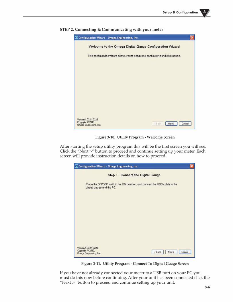
STEP 2. Connecting & Communicating with your meter
Figure 3-10. Utility Program - Welcome Screen
After starting the setup utility program this will be the first screen you will see.Click the “Next >” button to proceed and continue setting up your meter. Eachscreen will provide instruction details on how to proceed.
Figure 3-11. Utility Program - Connect To Digital Guage Screen
If you have not already connected your meter to a USB port on your PC youmust do this now before continuing. After your unit has been connected click the“Next >” button to proceed and continue setting up your unit.
Setup & Configuration 3
3-6

Figure 3-12. Utility Program - Verify Connections Screen
.
Figure 3-13. Utility Program - Establish Link Screen
After successful communication between your connector/transmitter has beenestablished you can click the “Next >” button to proceed and continue setting upyour connector/transmitter. If you did not receive this confirmation of propercommunication you should click the “Back” button to try connecting again
Setup & Configuration3
3-7

Figure 3-14. Utility Program - Choose Options Screen
From this screen you will select the main operating settings for your end device.(Note: Each end device must have a different address number for properoperation). After making your selections click the “Next >” button to proceedand program your settings into your unit.
(1) Backlight Options
Intensity
Here you can set how bright you want the backlighting to be when on. Keep inmind that when used under battery power the led brightness has a direct effecton the life of the battery. Keep to the lowest setting possible for your ambientlight conditions to conserve of battery power.
External Power
Here you can set the amount of time you want the backlighting to stay on whenactivated and the unit is running on external power. Note that you can only setthe backlighting to be “Always On” when the unit is powered by an externalpower supply. When set to 60 or 300 seconds the backlight will come on andthen turn off after the allotted time has expired.
Battery Power
Here you can set the amount of time you want the backlighting to stay on whenactivated and the unit is running on battery power only. Note that you can notset the backlighting to be “Always On” when the unit is powered by batterypower. When set to 10 or 30 seconds the backlight will come on and then turn offafter the allotted time has expired. If backlighting is not required it isrecommended that you select “Always Off” to preserve battery life.
Setup & Configuration 3
3-8

(1) Backlight Options
Intensity
Here you can set how bright you want the backlighting to be when on. Keep inmind that when used under battery power the led brightness has a direct effecton the life of the battery. Keep to the lowest setting possible for your ambientlight conditions to conserve of battery power.
External Power
Here you can set the amount of time you want the backlighting to stay on whenactivated and the unit is running on external power. Note that you can only setthe backlighting to be “Always On” when the unit is powered by an externalpower supply. When set to 60 or 300 seconds the backlight will come on andthen turn off after the allotted time has expired.
Battery Power
Here you can set the amount of time you want the backlighting to stay on whenactivated and the unit is running on battery power only. Note that you can notset the backlighting to be “Always On” when the unit is powered by batterypower. When set to 10 or 30 seconds the backlight will come on and then turn offafter the allotted time has expired. If backlighting is not required it isrecommended that you select “Always Off” to preserve battery life.
(2) Sensor Options
Sample Interval
Here you can set how oftern the device samples the sensor and updates the LCD.
The sample interval is always fixed at 0.382 seconds/sample(2.6 samples/second) when powered externally, regardless ofthe setting in the Configuration Wizard. The purpose of thesample interval setting is for conserving battery life, not fordisplay damping or averaging, and therefore has no effectunless operating on battery power only.
RTD Alpha
Select the proper curve for the sensor or probe you will be measuring with yourunit. Note, if you ordered a unit with an integral probe, this setting will befactory locked to match the probe installed.
(3) Front Panel Options
Show Decimal Point
Select this option to turn on or off the last digit and decimal point
Disable Keypad
Select this option to turn off the front keypad buttons. If selected during setupthe buttons will be locked and will not be activated by the magnetic stylus.
Setup & Configuration3
3-9
NOTE:

Disable Bar Graph
Select this option to remove the bar graph indicator from the display.
(4) Alarm Output
Alarm On
Disabled - The alarm output is disabled and will not operate.
Rising - The alarm output activates ONLY when the temperature meets orexceeds the High Setpoint.
Falling - The alarm output activates ONLY when the temperature meets or fallsbelow the Low Setpoint.
Rising & Falling - The alarm output activates when either the temperature meetsor exceeds the High Setpoint OR the temperature falls below the Low Setpoint
HAL (High Alarm Limit) Setpoint
Set here the high value you want the alarm to activate at.
HAL (High Alarm Limit) Deadband
Deadband is an area where no action occurs. The purpose is to preventoscillation or repeated activation-deactivation cycles. If your process value willalways be very close to your alarm setting you should adjust the deadband to bea few degrees different than your alarm value.
LAL (Low Alarm Limit) Setpoint
Set here the low value you want the alarm to activate at
LAL (Low Alarm Limit) Deadband
Deadband is an area where no action occurs. The purpose is to preventoscillation or repeated activation-deactivation cycles. If your process value willalways be very close to your alarm setting you should adjust the deadband to bea few degrees different than your alarm value.
(5) Analog Output Options
Mode
Select the type of analog output your application requires. You can leave thedefault setting if you will not be using the analog output feature.
Setup & Configuration 3
3-10

YOU MUST SET THE WIRE JUMPERS LOCATED ON THEBACK OF YOUR METER TO MATCH THE ANALOG OUTPUTTYPE YOU SELECTED HERE IN THE SETUP PROCESS.
Figure 3-15. Analog Output Options
Scaling
Here you can scale the analog output to correspond to the process reading value.
4-20 mA Example:
This table shows analog output values you should expect If you set 4mA = 0°Fand 20mA = 1000°F
Process Reading Analog Output Value
0°F 4.00 mA
250°F 8.00 mA
500°F 12.00 mA
750°F 16.00 mA
1000°F 20.00 mA
Setup & Configuration3
3-11
NOTE:
BATTERY
BATTERY
S1
4-20 mA SETTING0-5 Vdc/
0-10Vdc SETTING
BCA
B
C
A
B
C
A

0-10 Vdc Example:
This table shows analog output values you should expect If you set 0.0Vdc = 0°Fand 10.0 Vdc = 1000°F
Process Reading Analog Output Value
0°F 0.00 Vdc
250°F 2.50 Vdc
500°F 5.00 Vdc
750°F 7.50 Vdc
1000°F 10.00 Vdc
Figure 3-16. Calibration Options Screen - Skip Calibration Option
From this screen you will select a Calibration option. If the unit does not requirecalibration you should leave the default selected “Skip Calibration” andcontinue by clicking the “Next >”
Setup & Configuration 3
3-12

Figure 3-17. Calibration Options Screen - Skip To Next Option
After making your selections click the “Next >”
Figure 3-18. Send Settings To Digital Gauge Screen - Finish Option
After your meter has been programmed click the “Finish” button to close theutility program.
Setup & Configuration3
3-13

NOTES:
Setup & Configuration 3
3-14

Section 4 – Installation, Mounting & Wiring 4.1 Installation
Model DTG-RTD100 is NEMA 4X rated (Water tight, dust tight, corrosion-resistance - indoor & outdoor use). The meter can be installed in locations whereit will be intermittently exposed to spraying water, rain or high humidity. Themeter should never be used under water.
This meter is not designed for, tested, approved or certifiedfor use in intrinsically safe applications or for applicationswhere exposition proof instruments are required. Neveroperate in areas where flammable gases or material arepresent.
4.2 Ambient TemperatureYour meter should only be installed in locations that maintain an ambienttemperature between -40 to 70°C (-40 to 158°F)
4.3 General Meter Dimensions
Figure 4-1. General Meter Dimensions
4-1
Installation, Mounting & Wiring4
114.8(4.52)
89.2(3.51)
27.7(1.09)
74.2(2.92)
DIMENSIONS mm (in)
®
WARNING:

4.4 Battery Installation/ReplacementTo install or replace the battery in your End Device you must first remove thefour screws located on the Lid of the enclosure. This will allow you to removethe meter assembly and access the battery Holders.
Model DTG-RTD100 requires only one battery for normaloperation (Battery1). A second battery (Battery 2) can beadded to extend operation when on battery power. It is alsorecommended that thee additional battery (Battery 2) beinstalled for models that include the optional wirelesstransmitter.
Figure 4-2. Battery Installation/ Replacement
Lithium batteries may get hot, explode or ignite and cause serious injury ifexposed to abusive conditions. Be sure to follow the safety warnings listed below:
• Do not use a different battery other than what is specified in this manual orproduct data sheet.
• Do not discharge the battery using any device except your meter.
• Do not place the battery in fire or heat the battery.
• Do not store batteries with other hazardous or combustible materials.
• Do not install the battery backwards so the polarity is reversed.
• Do not connect the positive terminal and negative terminal of the battery toeach other with any metal object (such as wire).
• Do not carry or store the battery together with metal objects.
• Do not pierce the battery with nails, strike the battery with a hammer, step onthe battery or otherwise subject it to strong impacts or shocks.
• Do not solder directly onto the battery.
• Do not expose battery to water or salt water, or allow the battery to get wet.
• Do not disassemble or modify the battery.
Installation, Mounting & Wiring 4
4-2
BATTERY
BATTERY
BATTERY 1
BATTERY 2
+
–
+
–BC
A
NOTE:
• Immediately discontinue use of the battery if the battery emits an unusualsmell, feels hot, changes color or shape, leaks or appears abnormal in anyother way.
• Do not place the battery in microwave ovens or high-pressure containers.
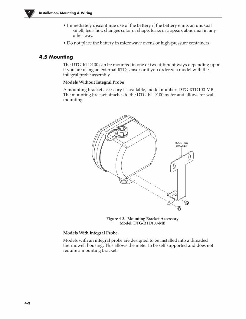
4.5 Mounting The DTG-RTD100 can be mounted in one of two different ways depending uponif you are using an external RTD sensor or if you ordered a model with theintegral probe assembly.
Models Without Integral Probe
A mounting bracket accessory is available, model number: DTG-RTD100-MB.The mounting bracket attaches to the DTG-RTD100 meter and allows for wallmounting.
Figure 4-3. Mounting Bracket AccessoryModel: DTG-RTD100-MB
Models With Integral Probe
Models with an integral probe are designed to be installed into a threadedthermowell housing. This allows the meter to be self supported and does notrequire a mounting bracket.
Installation, Mounting & Wiring4
4-3
MOUNTINGBRACKET

4.6 Wiring (Sensor, Power, Analog Output)
Figure 4-4. Wiring - Terminal Block Location
Temperature Sensor Wiring
Model DTG-RTD100 is designed to operate with a 3-wire, PT100 external sensoror integral probe assembly. Wires are connected to TB1 located on the rear circuitboard between the battery holder.
Figure 4-5. Wiring - Temperature Sensor Figure 4-6. Wiring - M12 Connector
Installation, Mounting & Wiring 4
4-4
TB2
TB1
BATTERY
BATTERY
ON/OFF SWITCH
TB1
RED WIRE BLACK WIRES
PT100SENSOR
1 32
M12 CONNECTOR
PT100SENSOR
RED WIRE BLACK WIRES

Power Supply Wiring Example
Figure 4-7. Wiring - Power Supply
Analog Output Wiring Example
Figure 4-8. Wiring - Analog Output
Installation, Mounting & Wiring4
4-5
J224 VDC
POWER SUPPLY ––
+
+
–+ –
+
CHART RECORDER
J1
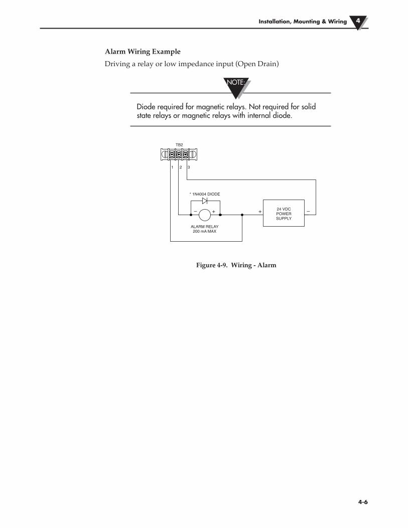
Alarm Wiring Example
Driving a relay or low impedance input (Open Drain)
Diode required for magnetic relays. Not required for solidstate relays or magnetic relays with internal diode.
Figure 4-9. Wiring - Alarm
Installation, Mounting & Wiring 4
4-6
TB2
* 1N4004 DIODE
ALARM RELAY200 mA MAX
24 VDCPOWERSUPPLY
+– –+
21 3
NOTE:

Section 5 – Display Features & Meter Operation 5.1 Display Features
Figure 5-1. Display Features
(1) Process Reading, (2) Units, (3) Bargraph, (4) Status Icons
5.2 Keypad Operation
Figure 5-2. Keypad Operations
(1) Mode Button, (2) Set Button
5-1
Display Features & Meter Operation5
°F0% 100%
MIN MAX AVG PEAKCALBAT HAL LAL LOGSET TX
23
1
4
®
1 2

Magnetic Stylus
A magnetic stylus is attached to your meter. This stylus is used to activate thefront buttons on the display. If you do not need to view the “MIN”, “MAX” or“AVERAGE” readings during normal operation, or have a need to turn thebacklight on during normal operation you can remove and store this stylus. Youwill need to select “Disable Keypad” during the setup and configuration process.
Figure 5-3. Magnetic Stylus
Button Operation
The “MODE” and “SET” buttons located of the front display of your meter areactivated by waving or taping the magnetic stylus included with your unitabove or onto the keypad button symbol on the front meter label.
Mode Button Operation – To activate the “MODE” button, place the tip of themagnetic stylus over the “MODE” button and hold for three seconds until theunit enters the “MODE” menu. Then move away the magnetic stylus. Each timethe magnetic stylus is again placed near the “MODE” button the meter will stepthrough each parameter.
“SET” Button Operation - The “SET” button has two primary functions.Independently the button is used to turn the backlighting on. To activate thebacklight, place the tip of the magnetic stylus over the “SET” button and hold forthree seconds until the backlighting turns on. The backlighting will remain onfor the amount of time you selected during the setup and configuration process.
If you selected “Always Off” when setting the meter up, thenthe “SET” button will not turn the backlighting on from thefront keypad.
When in the “MODE” menu, the “SET” button is used for the following:
1. To reset the MIN, MAX, or AVG values to the current temperature reading.All three are reset simultaneously, from any one of the three screens, MIN,MAX, or AVG.
2. To silence the High or Low alarm, when in the “HAL” or “LAL” screen andthe alarm is configured for “Latching”. This will cause the display to stopblinking, however, the alarm output will remain activated until the alarmcondition clears.
3. To turn the wireless transmitter “On” or “Off” while in the “WRLS” screen.
4. To select units of measure while in the “UNIT” screen.
Display Features & Meter Operation 5
5-2
MAGNETIC TIP
NOTE:

Figure 5-4. Menu Button Operation
Display Features & Meter Operation5
5-3
MENU MODEApply Magnet 3
Apply MagnetThen Remove
MIN, MAX AND AVG ALL SET TOVALUE OF CURRENT READING
MIN, MAX AND AVG ALL SET TOVALUE OF CURRENT READING
MIN, MAX AND AVG ALL SET TOVALUE OF CURRENT READING
BLINKING STOPSALARM SILENCED
BLINKING STOPSALARM SILENCED
BLINKING STOPSALARM SILENCED
Seconds Then Remove
Apply MagnetThen Remove
MIN VALUE
MAX VALUE
AVG VALUE
BATTERY VALUE
HIGH ALARM VALUE
LOW ALARM VALUE
Apply MagnetThen Remove
Apply MagnetThen Remove
Apply MagnetThen Remove
Apply MagnetThen Remove
Apply MagnetThen Remove
MODE0% 100%
MIN0% 100%
MIN
MAX0% 100%
MAX
AVG0% 100%
AVG
BATT0% 100%
BAT
HAL0% 100%
HAL
LAL0% 100%
LAL
MIN VALUE
MAX VALUEMIN0% 100%
MAX0% 100%
AVG VALUE
AVG0% 100%
HIGH ALARM VALUE
LOW ALARM VALUEHAL0% 100%
HAL
LAL0% 100%
LAL
Apply MagnetThen Remove
Apply MagnetThen Remove
Apply MagnetThen Remove
Apply MagnetThen Remove
Apply MagnetThen Remove
ContinuedNext Page
Apply MagnetThen Remove
WIRELESS OPTION WIRELESS OPTION
WIRELESS OPTION
Apply MagnetThen Remove
Apply MagnetThen Remove
WRLS0% 100% WRLS0% 100%
WRLS0% 100%

Figure 5-4. Menu Button Operation Continued
Display Features & Meter Operation 5
5-4
UNITS UNITS
UNITS
UNITS
EXIT MODE
UNITS
Continued from previous page
Apply MagnetThen Remove
Apply MagnetThen Remove
Apply MagnetThen Remove
Apply MagnetThen Remove
Apply MagnetThen Remove
Apply Magnet 3 Seconds Then
Remove
UNIT0% 100% F0% 100%
K0% 100%
0% 100%
EXIT0% 100%
RG 0% 100%

Backlighting Operation
The front keypad “Set” Button can be used to activate the backlighting feature.When activated, the backlighting will remain on for the period of time youselected during the setup and configuration in Section 3.
Figure 5-5. Front Keypad Set Button
Display Features & Meter Operation5
5-5
Apply Magnet 3 Seconds To Activate
Backlight

Section 6 – Optional Wireless Transmitter Operation6.1 Introduction
Compared to a wired connection, a wireless meter provides much simplerinstallation. Based on the physical principle of the propagation of radio waves,certain basic conditions should be observed. The following simplerecommendations are provided to Insure proper installation and correctoperation of your wireless meter.
6.2 RF Communication BasicsYour wireless transmitter sends wireless transmissions to a receiver. The receiverchecks the incoming data for accuracy and processes this data for use by themeasurement software on your PC. Radio signals are electromagnetic waves,hence the signal becomes weaker the further it travels. While radio waves canpenetrate some solid materials like a wall, they are dampened more than when adirect line-of-sight between the transmitting and receiving antenna exist.
6.3 Basic System OverviewA basic wireless temperature system is comprised of only two main components;a signal conditioner with a built-in battery powered 2.4GHz radio transmitter,and a USB powered 2.4GHz radio receiver.
Installation
When installing your meter it is important to position the unit in such a way asto optimize the antenna location within what’s known as the “Fresnel Zone”.
The Fresnel Zone can be thought of as a football-shaped invisible tunnel betweentwo locations that provides a path for RF signals between your meter and yourreceiver.
Figure 6-1. Fresnel Zone
6-1
Optional Wireless Transmitter Operation 6
FRESNEL ZONERECEIVERANTENNA
TRANSMITTER ANTENNA

In order to achieve maximum range, the football-shaped path in which radiowaves travel must be free of all obstructions. Obstacles in the path (especiallymetal) will decrease the communication range between your meter and receiver.Also, If the antennas are mounted just barely off the ground, over half of theFresnel zone ends up being obstructed by the earth resulting in significantreduction in range. To avoid this problem, the antennas should be mounted highenough off of the ground so that the earth does not interfere with the centraldiameter of the Fresnel zone.
It is important to understand that the environment maychange over time due to new equipment or machinery beinginstalled, building construction, etc. If new obstacles existbetween your meter and receiver, the devices can be raisedon one end or on both ends to clear the Fresnel Zone ofobstructions.
Installing your meter in an application were the unit will beexposed to ambient temperatures above or below theoperating limits specified in this manual will damage yourunit and cause the unit to malfunction and produce incorrectoperation.
Your meter has been shipped to you with a standardapproved antenna. Use of any other antenna than what’ssupplied with your meter will void all FCC, IC and CEregulatory compliance.
Environment
Omega’s wireless end devices and receiver units have been designed to be fixedmounted and operated in a clean and dry indoor environment. Care should betaken to prevent the components of your wireless system from being exposed tomoisture, toxic chemicals and extreme cold or hot temperature that are outsidethe specifications listed in this manual.
The following is a list of basic good practice you should apply when operatingyour wireless system.
• Never operate your wireless device or receiver outside the recommendedenvironmental limits specified in this manual.
• Never operate your wireless end device or receiver in flammable or explosiveenvironments.
Operational Wireless Transmitter Operation6
6-2
NOTE:
NOTE:
CAUTION:

• Never use your wireless end device or receiver in medical, nuclear or otherdangerous applications where an interruption of readings can causedamage or harm.
• Never operate your end device or receiver with any other battery or power sourcethan what’s specified in this manual or on the battery compartment label.
• No co-location with other radio transmitters is allowed. By definition, co-location is when another radio device or it’s antenna is located within 20 cmof your end device and can transmit simultaneously with your end device.
• Never install end devices within 20 cm or less from each other.
• Never use your end device as a portable device. Your unit has been designedto be operated in a permanent installation.
• Never install and/or operate your end device closer than 20 cm to nearbypersons.
• Never operate your end device with any other antenna than what is suppliedor listed here in this manual for approved use.
6.4 Transmit Rate vs. Battery LifeMany factors such as ambient temperature conditions and transmitting rate canhave a big effect on the life of the battery used in your meter. Transmitting dataplaces a big demand of the battery in your unit. The transmit rate is the singlemost contributing factor in the life of the battery. The slower the transmit rate youset, the longer the battery in your device will last. The tables and graphs belowgive some estimates on how long the battery should last vs. the transmit rate youselected when you setup your meter under normal operating conditions.
6.4.1 DTG-RTD100 Battery Life – Standard Model
Table 1: DTG-RTD100 - Standard Model - Battery Life
DTG-RTD100 Estimated Battery Life
Batteries: 4.8Ah x 1 4.8Ah x 2 8.5Ah x 1 8.5Ah x 2
Secondsper Sample: Weeks Weeks Weeks Weeks
0.38 21.6 43.1 38.2 76.3
0.5 26.2 52.4 46.4 92.7
1 38.6 77.1 68.3 136.6
2 50.5 101.1 89.5 179.0
3 56.4 112.7 99.8 199.6
4 59.8 119.6 105.9 211.8
5 62.1 124.2 110.0 219.9
10 67.2 134.4 119.0 238.1
15 69.1 138.2 122.4 244.8
30 71.1 142.3 126.0 251.9
Operational Wireless Transmitter Operation 6
6-3

Operational Wireless Transmitter Operation6
6-4
6.4.2 DTG-RTD100-W Battery Life – Wireless Model
For the DTG-RTD100-W digital RTD meter, the battery life of the device iscontrolled by three variables – the battery capacity, the analog output rate, andthe wireless transmission rate. The battery capacity can either be 9600 mA hours(using 2 of the 4.8Ah capacity batteries), or 17,000 mA hours (using 2 of the8.5Ah capacity batteries). Below are two tables showing the battery life estimatesin both scenarios, at various analog output rates.
Table 2: DTG-RTD100-W - Wireless Model – Battery Life (2 x 4.8Ah Batteries)
DTG-RTD100-W Estimated Battery Life
(2 x 4.8Ah Batteries: 9600 mA Hours)
Analog Seconds/Sample: .5 5 15 30
Seconds perWireless Transmission: Weeks Weeks Weeks Weeks
2 31.8 48.8 50.9 51.4
3 36.6 61.2 64.4 65.3
5 41.6 76.8 81.9 83.3
10 46.5 94.9 102.9 105.1
15 48.3 103.1 112.5 115.1
30 50.3 112.7 124.1 127.3
45 51.0 116.3 128.5 131.9
60 51.4 118.2 130.8 134.4
120 52 121.2 134.4 138.2
RF OFF 52.5 124.3 138.3 142.3

Operational Wireless Transmitter Operation 6
6-5
Table 3: DTG-RTD100-W - Wireless Model – Battery Life (2 x 8.5Ah Batteries)
DTG-RTD100-W Estimated Battery Life
(2 x 8.5Ah Batteries: 17,000 mA Hours)
Analog Seconds/Sample: .5 5 15 30
Seconds per WirelessTransmission: Weeks Weeks Weeks Weeks
2 56.3 86.5 90.1 91.0
3 64.8 108.4 114.1 115.6
5 73.7 136.0 145.1 147.6
10 82.3 168.1 182.2 186.1
15 85.6 182.5 199.2 203.9
30 89.1 199.5 219.7 225.4
45 90.4 205.9 227.5 233.6
60 91.0 209.3 231.6 237.9
120 92.0 214.5 238.0 244.7
RF OFF 93.0 220.1 244.9 251.9

6-6
Operational Wireless Transmitter Operation6
6.5 Wireless Transmitter SetupAfter connecting the USB cable and running the configuration software asoutlined in Section 3, you will complete the following steps to configure yourwireless transmitter before placing the unit into operation. You will be using theconfiguration software utility that you installed onto your PC in Section 3. Ifyou have not installed the configuration software utility you should do so now.
During this procedure you will be setting the following parameters in yourtransmitter.
RF Channel
This setting determines the operating channel on which RF connections aremade between the transmitter and receiver. The transmitter must be set to thesame channel as the receiver in order for them to communicate.
Network ID
This sets the ID of the Network that the transmitter will be joining. It mustmatch the setting of the receiver in order for them to communicate.
Receiver Address
This sets a unique address number for your receiver. Later, when you set upyour receiver you will again set the same number to receive readings from thecorresponding transmitter unit(s). Each receiver must be set for a differentnumber for your system to operate correctly.
If you will be using more than one receiver unit in your area itis important to set the transmitter address numbers to be acorresponding number in your TC-Central software. SeeExamples below.
For the first receiver:
Set the address on your transmitters to 101, 102, 103, 104, etc. Then set theaddress in your TC-Central software to match.
For the second receiver:
Set the channels on your transmitters to 201, 202, 203, 204, etc. Then set theaddress in your TC-Central software to match.
This numbering scheme can be expanded to match the number of receivers youare using.
Gauge Address
This sets a unique address number into your transmitter. Later, when you set upyour measurement software you will use this address setting to receive readingsfrom the corresponding unit(s). Each transmitter must be set for a differentaddress for your system to operate correctly.
Wireless Transmission Rate
This will program your device to transmit 1 data reading to your receiver at aspecified time interval. Available settings are 2, 3, 4, 5, 10, 15, 20, 25, 30, 45, 60, 75,90, 105 or 120 seconds.
NOTE:

7-1
DTG-RTD100 Design for CE Conformity 7
Section 7 - DTG-RTD100 Design for CE Conformity All models of the DTG-RTD100 Digital RTD Meter have been designed to meetrequirements as outlined in European Community EMC Directive EN50081-1/EN50082-1. Two ferrite cores and an output grounding cable are included inyour DTG-RTD100 package; you must install the cable and both ferrite cores inorder to meet radiated immunity specifications.
7.1 DTG-RTD100 Analog Output GroundingThe analog output cable is supplied with accompanying grounding hardware.The figures below specify the wiring and procedure required to properly groundyour DTG-RTD100 unit.
Figure 7-1. Analog Output Wiring Example
Figure 7-2. Analog Output Grounding Example
SHIELD WIRE(TWISTEDAROUNDHARDWARE)
GROUNDINGHARDWARE
ANALOG OUTPUTCABLE (TX4)
–+ –
+
CHART RECORDER
J1
ENCLOSURESHIELD WIRE
GROUND

DTG-RTG100 Design for CE Conformity7
7-2
7.2 Ferrite CoreAll models of the DTG-RTD100 Digital RTD Meter have been designed to meetrequirements as outlined in European Community EMC Directive EN50081-1/EN50082-1. Two ferrite cores and an output grounding cable are included inyour DTG-RTD100 package; you must install the cable and both ferrite cores inorder to meet radiated immunity specifications.
To install the grounding output cable for your meter, refer to Section 4, Figure 4-8.
Figure 7-3. Ferrite Core
In order to conform to CE standards, the ferrite cores must be attached to thegrounding output cable of the DTG-RTD100 as shown in Figure 7-4.
The ferrite cores MUST be secured on opposite ends of theoutput cable.
Figure 7-4. Ferrite Core Installation
NOTE:
OUTPUT CABLE
ATTACH FERRITE CORESTO OPPOSITE ENDS OFTHE OUTPUT CABLE

Section 8 – Service & CalibrationYour DTG-RTD100 Thermometer has been built, tested and factory calibrated tomeet or exceed the specifications listed here in this manual. Information isprovided below on how to have your unit returned for service.
If your meter requires service or factory re-calibration, please call our CustomerService Department at 1-800-622-2378 or 203-359-1660. They will assist you inarranging the return of your meter. We can also be reached on the Internet atwww.omega.com, e-mail: [email protected]
8-1
Service & Calibration 8

9-1
Specifications9
Section 9 – Specifications9.1 General
Range: -51 to 538°C (-60 to 1000°F)
Accuracy: ±0.2°C (±0.3°F) or ±0.1% of reading, Whatevergreater
Resolution: 0.1°C (0.1°F)
Operating Environment: -40 to 70°C (-40 to 158°F); 5 to 100% RH non-condensing
RTD Probe/ Sensor Input: Pt100, 3-wire
Display Type: LCD with selectable backlight
Display Digits: 4 digits, 9999 counts
Character Height: 25.4 mm (1.0 in)
Computer Interface: USB (one programming cable included)
Sample/ Display Rate: 1/second default, user adjustable from 1/0.375 sec.to 1/30 sec.
Battery Power: One or Two 3.6V lithium, 8.4 Ah capacity (C-cell)one included
External Power: 12 to 24 Vdc (required for analog output operation)
Battery Life (Typical): See section 6.4
Analog Output: User selectable 0 to 5 Vdc, 0 to 10 Vdc, or 4 to 20mA; Requires external 12 to 24 Vdc power supplyfor operation
Enclosure: 316 Stainless Steel housing, ABS center gasket
Enclosure Finish: Electropolished
Enclosure Rating: Weatherproof, NEMA 4 (IP65)
Enclosure Screw Torque: 20 oz in.
Dimensions: 4.53" H*, 4.52" W, 2.92" D (*height not including sensor)
Weight: 1.59 lbs.
Settings (USB/ Software)Units: °C, °F, °K, °R
Lock: Allows for front button lock-out
Alarms: User selectable high and low alarm limits
Backlight: On/off, or 10 sec, 30 sec, 1 min, 5 min
Backlight Color: Normal Operation – Green, Low Alarm – Blue, HighAlarm - Red

9.2 Wireless OptionTransmit Sample Rate: User programmable from 1 sample/2 min to 1
sample/every 2 sec
Radio Frequency (RF) Transceiver Carrier: ISM 2.4 GHz
RF Output Power: 10 dBm (10 mW)
Range of RF Link:Outdoor Line of Sight: Up to 120 m (400 ft)Indoor/ Urban: Up to 40 m (130 ft)
Software (Included Free): Requires Windows® 2000, XP or Vista (32 bit)
Data Transmitted to Host: Temperature reading, ambient temperature reading,RF transmit strength and battery level
Specifications 9
9-2

10-1
Approval, Regulatory Compliance10
Section 10 – Approvals, Regulatory Compliance
All approvals outlined in this manual are based on testingthat was done with antennas that are supplied with yourmeter. Removing and or installing a different antenna willvoid the product compliance demonstrated in thesedocuments.
10.1 FCC (Domestic Use)For United States: FCC ID: OUR-XBEEPROFor Canada: IC #4214A-XBEEPRO
This device complies with Part 15 of the FCC rules. Operation is subject to thefollowing two conditions: 1.) This device may not cause harmful interference. 2.)This device must accept any interference received, including interference thatmay cause undesired operation.
To satisfy FCC RF exposure requirements for mobiletransmitting devices, a separation distance of 20 cm or moreshould be maintained between the antenna of this device andpersons during device operation. To ensure compliance,operations at closer than this distance is not recommended.The antenna used for this transmitter must not be co-locatedin conjunction with any other antenna or transmitter.
10.2 International Usage & CE Marking
It is your (the user’s) responsibility to insure that theseproducts are operated within the guidelines here in thismanual and in conformance with all local, state, federal ornational regulations and laws of the country they are beingoperated in.
Transmitting Power - Your Wireless Series SystemComponents have been designed, manufactured and testedso that the transmitting power of your wireless meter will notexceed 10 dBm.
NOTE:
NOTE:
NOTE:
WARNING:

WARRANTY/DISCLAIMEROMEGA ENGINEERING, INC. warrants this unit to be free of defects in materials and workmanship for aperiod of 13 months from date of purchase. OMEGA’s WARRANTY adds an additional one (1) monthgrace period to the normal one (1) year product warranty to cover handling and shipping time. Thisensures that OMEGA’s customers receive maximum coverage on each product. If the unit malfunctions, it must be returned to the factory for evaluation. OMEGA’s Customer ServiceDepartment will issue an Authorized Return (AR) number immediately upon phone or written request.Upon examination by OMEGA, if the unit is found to be defective, it will be repaired or replaced at nocharge. OMEGA’s WARRANTY does not apply to defects resulting from any action of the purchaser,including but not limited to mishandling, improper interfacing, operation outside of design limits, improper repair, or unauthorized modification. This WARRANTY is VOID if the unit shows evidence of having been tampered with or shows evidence of having been damaged as a result of excessive corrosion;or current, heat, moisture or vibration; improper specification; misapplication; misuse or other operatingconditions outside of OMEGA’s control. Components in which wear is not warranted, include but are not limited to contact points, fuses, and triacs.OMEGA is pleased to offer suggestions on the use of its various products. However, OMEGA neither assumes responsibility for any omissions or errors nor assumes liability for anydamages that result from the use of its products in accordance with information provided byOMEGA, either verbal or written. OMEGA warrants only that the parts manufactured by thecompany will be as specified and free of defects. OMEGA MAKES NO OTHER WARRANTIES OR REPRESENTATIONS OF ANY KIND WHATSOEVER, EXPRESSED OR IMPLIED, EXCEPT THAT OFTITLE, AND ALL IMPLIED WARRANTIES INCLUDING ANY WARRANTY OF MERCHANTABILITYAND FITNESS FOR A PARTICULAR PURPOSE ARE HEREBY DISCLAIMED. LIMITATION OF LIABILITY: The remedies of purchaser set forth herein are exclusive, and the total liability of OMEGA with respect to this order, whether based on contract, warranty, negligence, indemnification, strict liability or otherwise, shall not exceed the purchase price of the component upon which liability is based. In no event shall OMEGA be liable for consequential, incidental or special damages.CONDITIONS: Equipment sold by OMEGA is not intended to be used, nor shall it be used: (1) as a “BasicComponent” under 10 CFR 21 (NRC), used in or with any nuclear installation or activity; or (2) in medicalapplications or used on humans. Should any Product(s) be used in or with any nuclear installation oractivity, medical application, used on humans, or misused in any way, OMEGA assumes no responsibilityas set forth in our basic WARRANTY/DISCLAIMER language, and, additionally, purchaser will indemnifyOMEGA and hold OMEGA harmless from any liability or damage whatsoever arising out of the use of theProduct(s) in such a manner.
RETURN REQUESTS/INQUIRIESDirect all warranty and repair requests/inquiries to the OMEGA Customer Service Department. BEFORERETURNING ANY PRODUCT(S) TO OMEGA, PURCHASER MUST OBTAIN AN AUTHORIZED RETURN(AR) NUMBER FROM OMEGA’S CUSTOMER SERVICE DEPARTMENT (IN ORDER TO AVOIDPROCESSING DELAYS). The assigned AR number should then be marked on the outside of the returnpackage and on any correspondence.The purchaser is responsible for shipping charges, freight, insurance and proper packaging to preventbreakage in transit.
FOR WARRANTY RETURNS, please have the following information available BEFORE contacting OMEGA:1. Purchase Order number under which the product
was PURCHASED,2. Model and serial number of the product under
warranty, and3. Repair instructions and/or specific problems
relative to the product.
FOR NON-WARRANTY REPAIRS, consult OMEGAfor current repair charges. Have the followinginformation available BEFORE contacting OMEGA:1. Purchase Order number to cover the COST
of the repair,2. Model and serial number of the product, and3. Repair instructions and/or specific problems
relative to the product.
OMEGA’s policy is to make running changes, not model changes, whenever an improvement is possible. This affordsour customers the latest in technology and engineering.OMEGA is a registered trademark of OMEGA ENGINEERING, INC.© Copyright 2012 OMEGA ENGINEERING, INC. All rights reserved. This document may not be copied, photocopied,reproduced, translated, or reduced to any electronic medium or machine-readable form, in whole or in part, without theprior written consent of OMEGA ENGINEERING, INC.

M4778/1012
Where Do I Find Everything I Need forProcess Measurement and Control?
OMEGA…Of Course!Shop online at omega.com SM
TEMPERATURE�� Thermocouple, RTD & Thermistor Probes, Connectors, Panels & Assemblies�� Wire: Thermocouple, RTD & Thermistor�� Calibrators & Ice Point References�� Recorders, Controllers & Process Monitors�� Infrared Pyrometers
PRESSURE, STRAIN AND FORCE�� Transducers & Strain Gages�� Load Cells & Pressure Gages�� Displacement Transducers�� Instrumentation & Accessories
FLOW/LEVEL�� Rotameters, Gas Mass Flowmeters & Flow Computers�� Air Velocity Indicators�� Turbine/Paddlewheel Systems�� Totalizers & Batch Controllers
pH/CONDUCTIVITY�� pH Electrodes, Testers & Accessories�� Benchtop/Laboratory Meters�� Controllers, Calibrators, Simulators & Pumps�� Industrial pH & Conductivity Equipment
DATA ACQUISITION�� Data Acquisition & Engineering Software�� Communications-Based Acquisition Systems�� Plug-in Cards for Apple, IBM & Compatibles�� Data Logging Systems�� Recorders, Printers & Plotters
HEATERS�� Heating Cable�� Cartridge & Strip Heaters�� Immersion & Band Heaters�� Flexible Heaters�� Laboratory Heaters
ENVIRONMENTALMONITORING AND CONTROL�� Metering & Control Instrumentation�� Refractometers�� Pumps & Tubing�� Air, Soil & Water Monitors�� Industrial Water & Wastewater Treatment�� pH, Conductivity & Dissolved Oxygen Instruments