
MacroPower COMBIMOULD - WITTMANN Group
13
world of innovation world of innovation MacroPower COMBIMOULD 400 – 2000 t The flexible large-molding machine
Transcript of MacroPower COMBIMOULD - WITTMANN Group

world of innovationworld of innovation
MacroPower COMBIMOULD 400 – 2000 t The flexible large-molding machine
2
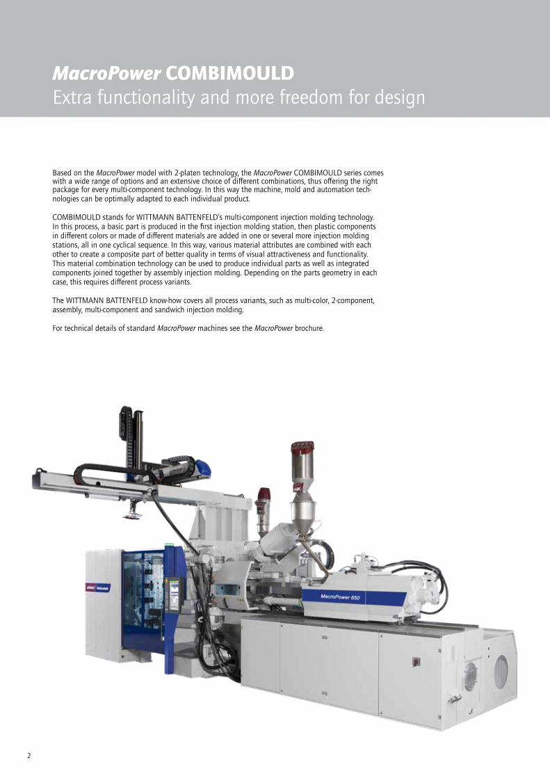
MacroPower COMBIMOULDExtra functionality and more freedom for design
Based on the MacroPower model with 2-platen technology, the MacroPower COMBIMOULD series comes with a wide range of options and an extensive choice of different combinations, thus offering the right package for every multi-component technology. In this way the machine, mold and automation tech-nologies can be optimally adapted to each individual product.
COMBIMOULD stands for WITTMANN BATTENFELD’s multi-component injection molding technology. In this process, a basic part is produced in the first injection molding station, then plastic components in different colors or made of different materials are added in one or several more injection molding stations, all in one cyclical sequence. In this way, various material attributes are combined with each other to create a composite part of better quality in terms of visual attractiveness and functionality. This material combination technology can be used to produce individual parts as well as integrated components joined together by assembly injection molding. Depending on the parts geometry in each case, this requires different process variants.
The WITTMANN BATTENFELD know-how covers all process variants, such as multi-color, 2-component, assembly, multi-component and sandwich injection molding.
For technical details of standard MacroPower machines see the MacroPower brochure.

3
MacroPower COMBIMOULDApplications
» Hard-soft combinations and overmolded sealing components The use of thermoplastic elastomers allows direct overmolding of sealing components. Moreover, the surface touch can be improved by adding a soft component. The bonding strength can be increased by mechanical anchoring. Multi-component technology is also frequently used in LIM processes (liquid silicon processing).
» Multi-color injection molding Several parts made of the same material but in different colors are combined into one component. Classic examples are multi-colored bottle cases with soft-handles and the frames for flat screens (LED TV sets, computers, laptops etc.) with piano finish effect. Multi-color injection molding improves the appearance of parts with guaranteed colorfastness.
» In-Mold Assembling Parts consisting of two halves can be joined together directly in the mold. For example, to make this two-component oil closure, its two halves are injected in separate stations with the help of cube molds, then, following rotation, brought together in the 3rd station by closing the mold. But jointed connections can also be injected in one production step. Non-adhesive mate-rials are chosen for this purpose. Ball joints and hings can easily be formed in this way.
» Sandwich injection molding – co-injection technology This process serves to produce parts with a three-layer structure, consisting of two continuous outer surface layers and a core layer. This is achieved by consecutive injection of two materials through the same nozzle into a conventional mold. A foamed or reinforced core component improves the part’s mechanical attributes. Costs can be reduced by using regrind and CELLMOULD® foam technology. The surface layers consisting of high-grade materials provide the desired high-quality surface attributes. In the packaging indus-try, barrier layers can be incorporated in the parts. Re-producible, attractive marbling effects can be achieved by switching several times between two materials of different colors. Depending on the area of application and the requirements to be met by the production equipment, a sandwich adapter plate, a sandwich and interval nozzle or a “monosandwich” process is used.
Photo: Haidlmair GmbH
4
COMBIMOULD PROCESS TECHNOLOGYOptimally coordinated solution
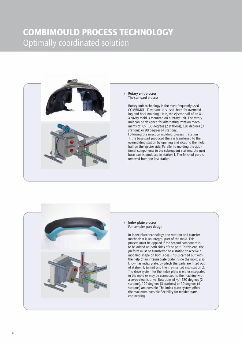
» Rotary unit process The standard process Rotary unit technology is the most frequently used COMBIMOULD variant. It is used both for overmold-ing and back molding. Here, the ejector half of an X + X-cavity mold is mounted on a rotary unit. The rotary unit can be designed for alternating rotation move-ments of +/- 180 degrees (2 stations), 120 degrees (3 stations) or 90 degrees (4 stations). Following the injection molding process in station 1, the base part produced there is transferred to the overmolding station by opening and rotating the mold half on the ejector side. Parallel to molding the addi-tional components in the subsequent stations, the next base part is produced in station 1. The finished part is removed from the last station.
» Index plate process For complex part design In index plate technology, the rotation and transfer mechanism is an integral part of the mold. This process must be applied if the second component is to be added on both sides of the part. To this end, the preform must be transferred to a station to receive a modified shape on both sides. This is carried out with the help of an intermediate plate inside the mold, also known as index plate, by which the parts are lifted out of station 1, turned and then re-inserted into station 2. The drive system for the index plate is either integrated in the mold or may be connected to the machine with a servo-electric drive. Rotations of +/- 180 degrees (2 stations), 120 degrees (3 stations) or 90 degrees (4 stations) are possible. The index plate system offers the maximum possible flexibility for molded parts engineering.

5
» Transfer process For special cases and small series projects This process is used as an alternative to the index plate process where the molded part No. 1, due to its geom-etry, has an insufficient contact area on the index plate for being transported by the index plate between the injection molding stations. Other types of applications are combinations of bulky inserts (such as screwdrivers or knife blades) with plastic components, or a low-cost production alternative for small series.
» Valve gate retraction process To add flat components without parts transfer In valve gate technology, the second component is added without prior mold opening and rotation. The different geometry required inside the cavity is pro-duced by a hydraulic valve gate which, when retracted, provides the space for adding the second component. In spite of a longer cycle time due to serial produc-tion steps, the valve gate process may be of interest economically in mold technology for small numbers of units because of the lower cost of mold technology. In some cases, the compact mold design even allows the use of smaller machines. However, a possible use strongly depends on the design of the molded part and on flat geometries of the additions.
6
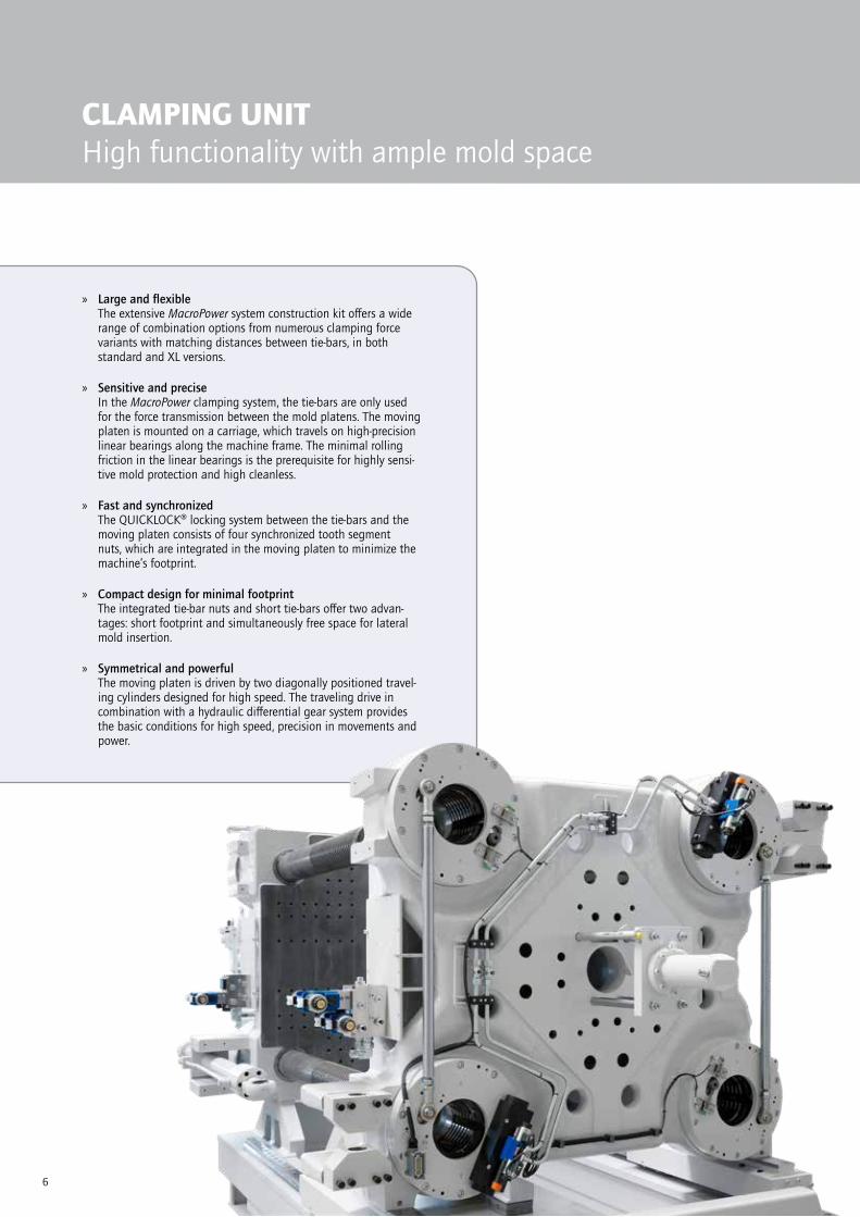
CLAMPING UNITHigh functionality with ample mold space
» Large and flexible The extensive MacroPower system construction kit offers a wide range of combination options from numerous clamping force variants with matching distances between tie-bars, in both standard and XL versions.
» Sensitive and precise In the MacroPower clamping system, the tie-bars are only used for the force transmission between the mold platens. The moving platen is mounted on a carriage, which travels on high-precision linear bearings along the machine frame. The minimal rolling friction in the linear bearings is the prerequisite for highly sensi-tive mold protection and high cleanless.
» Fast and synchronized The QUICKLOCK® locking system between the tie-bars and the moving platen consists of four synchronized tooth segment nuts, which are integrated in the moving platen to minimize the machine’s footprint.
» Compact design for minimal footprint The integrated tie-bar nuts and short tie-bars offer two advan-tages: short footprint and simultaneously free space for lateral mold insertion.
» Symmetrical and powerful The moving platen is driven by two diagonally positioned travel-ing cylinders designed for high speed. The traveling drive in combination with a hydraulic differential gear system provides the basic conditions for high speed, precision in movements and power.

7
CLAMPING UNITFast rotation units
The optional, adaptive rotary table comes with a servo-electric drive and is laid out for a rotation angle of 360° or +/-180°. In addition, it is characterized by extremely low installation height, high dynamics, flexibility, safety and gentle treatment of the mold.
» Highly dynamic servo motor – Minimal rotation times – Parallel movements – Shorter cycle times
» Short changeover times – Very low installation height – Easy and flexible installation and removal – Unit can be deactivated via control-system
» Safety and mold protection – Dampened end position control – Indexing device
» Extension of the standard version by various options – 3-station (120°) or 4-station (90°) processes – Additional media circuits – Individual ejector positions – Magnetic clamping plate
Best accessfor rotation devicesRotation devices for the required media, for temperature control, hydraulics and pneumatics can be supplied with up to 12 circuits. The 2-platen technology design of the MacroPower machines ensures optimal access to its media supply connections.

8
INJECTION UNITConfigurations
Injection unitConfiguration
The MacroPower COMBIMOULD offers a choice of V, S and L configurations as standard. Special configurations, such as the Y, B or H-H configuration, are available upon request.
» V configuration Injection from above, also into the mold parting line
– Generous adjustment range – Sliding unit with linear guides – Easy horizontal adjustment – Complete V aggregate can be moved back to pro-vide an absolutely free mold space
» S configuration Slanted above horizontal injection unit
– Compact machine design – Small footprint – S and H aggregates can be moved independently – Independent, adjustable, torque-free nozzle contact pressure
– Excellent access to the nozzle
» L configuration Injection from the non-operator side, also into the mold parting line
– Sliding unit freely mounted on the back of the fixed platen
– Injection unit supported by linear guides – Long adjustment path – Access to the nozzle and to the mold from the rear via large operator safety gate
– Fixed platen kept free for standard linear robot
» B configuration Injection unit on the moving platen
– For cube technology – Injection into the moving mold half
» H-H configuration 2 parallel horizontal aggregates
– Both aggregates can be moved independently – For sandwich technology – Excellent thermal insulation of each aggregate
9
DRIVE TECHNOLOGYEnergy efficient and modular
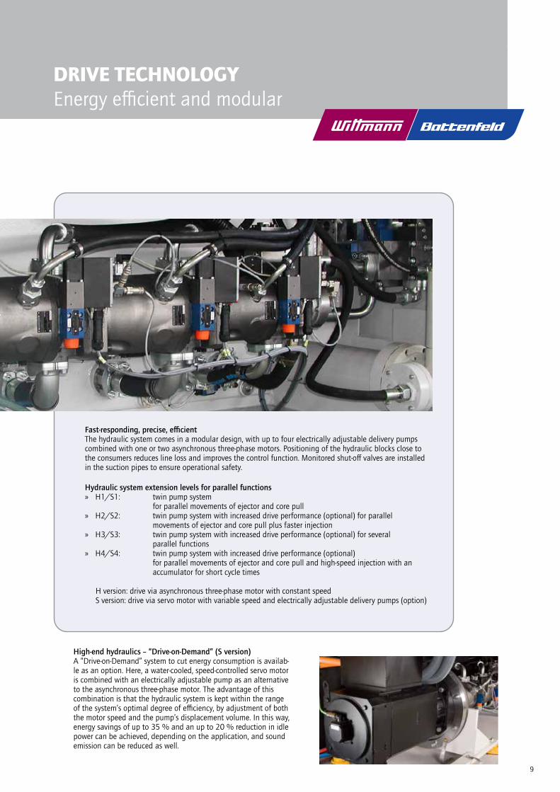
Fast-responding, precise, efficientThe hydraulic system comes in a modular design, with up to four electrically adjustable delivery pumps combined with one or two asynchronous three-phase motors. Positioning of the hydraulic blocks close to the consumers reduces line loss and improves the control function. Monitored shut-off valves are installed in the suction pipes to ensure operational safety.
Hydraulic system extension levels for parallel functions » H1/S1: twin pump system
for parallel movements of ejector and core pull » H2/S2: twin pump system with increased drive performance (optional) for parallel
movements of ejector and core pull plus faster injection » H3/S3: twin pump system with increased drive performance (optional) for several
parallel functions » H4/S4: twin pump system with increased drive performance (optional)
for parallel movements of ejector and core pull and high-speed injection with an accumulator for short cycle times
H version: drive via asynchronous three-phase motor with constant speedS version: drive via servo motor with variable speed and electrically adjustable delivery pumps (option)
High-end hydraulics – “Drive-on-Demand” (S version)A “Drive-on-Demand” system to cut energy consumption is availab-le as an option. Here, a water-cooled, speed-controlled servo motor is combined with an electrically adjustable pump as an alternative to the asynchronous three-phase motor. The advantage of this combination is that the hydraulic system is kept within the range of the system’s optimal degree of efficiency, by adjustment of both the motor speed and the pump’s displacement volume. In this way, energy savings of up to 35 % and an up to 20 % reduction in idle power can be achieved, depending on the application, and sound emission can be reduced as well.
10
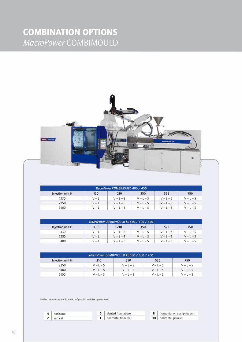
COMBINATION OPTIONSMacroPower COMBIMOULD
H horizontalV vertical
S slanted from aboveL horizontal from rear
B horizontal on clamping unitHH horizontal parallel
Further combinations and B or H-H configuration available upon request.
Further combinations and B or H-H configuration available upon request.
MacroPower COMBIMOULD 400 / 450
Injection unit H 130 210 350 525 750
1330 V − L V − L − S V − L − S V − L − S V − L − S2250 V − L V − L − S V − L − S V − L − S V − L − S3400 V − L V − L − S V − L − S V − L − S V − L − S
MacroPower COMBIMOULD XL 450 / 500 / 550
Injection unit H 130 210 350 525 750
1330 V − L V − L − S V − L − S V − L − S V − L − S2250 V − L V − L − S V − L − S V − L − S V − L − S3400 V − L V − L − S V − L − S V − L − S V − L − S
MacroPower COMBIMOULD XL 550 / 650 / 700
Injection unit H 210 350 525 750
2250 V − L − S V − L − S V − L − S V − L − S3400 V − L − S V − L − S V − L − S V − L − S5100 V − L − S V − L − S V − L − S V − L − S

11
Further combinations and B or H-H configuration available upon request.
MacroPower COMBIMOULD XL 1100 / 1300 / 1500 / 1600
Injection unit H 350 525 750 1000 1330 2250
5100 L − S L − S L − S L L L
8800 L − S L − S L − S L L L
12800 L − S L − S L − S L L L
MacroPower COMBIMOULD XL 1600 / 1800 / 2000
Injection unit H 350 525 750 1000 1330 2250
12800 L − S L − S L − S L L L
16800 L − S L − S L − S L L L
19000 L − S L − S L − S L L L
MacroPower COMBIMOULD XL 700 / 850 / 900
Injection unit H 350 525 750 1000
2250 V − L − S V − L − S V − L − S L
3400 V − L − S V − L − S V − L − S L
5100 V − L − S V − L − S V − L − S L
MacroPower COMBIMOULD XL 900 / 1000 / 1100
Injection unit H 350 525 750 1000 1330
3400 L − S L − S L − S L L
5100 L − S L − S L − S L L
8800 L − S L − S L − S L L

15
TPE based on polyamide
TPE-polyester-elastomers
TPE based on polyolefin
TPE based on styrene
TPE thermoplas-tic plyurethane
TPE types with modified adhe-sive properties
ABS ■ ■ ■ ■ ▲ ▲
ASA ▲ ▲
CA ▲
PA 6 ▲ ■ ■ ▲ ▲
PA 6.6 ▲ ■ ▲ ▲
PA-Blend ▲ ■ ■ ▲
PBTP ■ ■ ▲ ■ ▲
PC ■ ■ ■ ■ ▲ ▲
PC/ABS ■ ■ ■ ■ ▲ ▲
PC/PBT ■ ■ ■ ■ ▲ ▲
PC/PET ■ ■ ■ ■ ▲ ▲
PE ■ ■ ■ ▲
PETP ■ ▲
PMMA ■ ■ ▲
POM ■ ▲ ▲
PP ■ ■ ▲ ▲
PPO ■ ▲
PS ■ ■ ■ ▲
PAN ■ ▲ ▲
ABS
ASA
CA PA 6
PA 6
.6
PA-B
lend
PBTP PC
PC/A
BS
PC/P
BT
PC/P
ET
PE PETP
PMM
A
POM
PP PPO
PS SAN
TPE/
TPU
ABS ▲ ▲ ▲ ▲ ▲ ▲ ▲ ▲ ▲ ▲ ■ ▲ ▲ ■ ■ ■ ■
ASA ▲ ▲ ▲ ▲ ▲ ▲ ▲ ▲ ▲ ■ ▲ ▲ ■ ■ ■ ■ ▲ ■
CA ▲ ▲ ▲ ▲ ■ ■ ■ ■
PA 6 ▲ ▲ ▲ ▲ ▲ ■ ▲ ▲ ▲ ■ ■ ■ ■ ■ ■
PA 6.6 ▲ ▲ ▲ ▲ ▲ ■ ▲ ▲ ▲ ■ ■ ■ ■ ■ ■
PA-Blend ▲ ▲ ▲ ■ ■ ■ ■
PBTP ▲ ▲ ▲ ▲ ■ ▲ ▲ ▲ ▲ ▲ ■ ▲ ■ ■ ■ ■ ▲ ■
PC ▲ ▲ ▲ ▲ ▲ ▲ ▲ ▲ ■ ▲ ■ ■ ■ ▲ ■
PC/ABS ▲ ▲ ▲ ▲ ▲ ▲ ▲ ▲ ■ ■ ■ ■ ■
PC/PBT ▲ ▲ ▲ ▲ ▲ ▲ ▲ ▲ ▲ ■ ▲ ▲ ■ ■ ■ ■
PC/PET ▲ ▲ ▲ ▲ ▲ ▲ ▲ ▲ ▲ ■ ▲ ▲ ■ ■ ■ ■
PE ■ ■ ■ ■ ■ ■ ▲ ▲ ■ ▲
PETP ▲ ▲ ▲ ▲ ▲ ▲ ■ ▲ ■
PMMA ▲ ▲ ■ ▲ ▲ ■ ▲ ■ ■ ■ ▲ ■
POM ■ ■ ■ ■ ■ ■ ■ ■ ■ ■ ■ ■ ▲ ■
PP ■ ■ ■ ■ ■ ■ ■ ■ ■ ■ ■ ▲ ■
PPO ■ ■ ■ ■ ■ ■ ■ ■ ▲ ■
PS ■ ■ ■ ■ ■ ■ ■ ■ ■ ■ ▲ ▲ ■
SAN ■ ▲ ▲ ▲ ▲ ■ ■ ■ ■ ▲ ■ ■ ▲ ▲
TPE/TPU ■ ■ ■ ■ ■ ■ ■ ■ ■ ■ ▲ ■ ■ ■ ▲ ■ ■ ▲ ▲
■ limited bonding
■ no bonding
▲ good bonding
▲ excellent bonding
Bonding of hard-soft material combinations
Bonding of thermoplastic materials in multi-component injection molding
Due to the great variety of TPE types, the bonding strength must be checked in each individual case.
The bonding strength also depends on the part geometry, process conditions and processes involved.
In some cases, par-ticularly where modified materials are involved, tests must be carried out to check the bonding strength.

WITTMANN BATTENFELD GmbH
Wiener Neustädter Strasse 81
2542 Kottingbrunn | Austria
Tel.: +43 2252 404-0
www.wittmann-group.comM
acro
Pow
er C
OM
BIM
OU
LD |
Art
icle
num
ber:
BPK0
0000
09 (
Engl
ish)
| 2
019/
09|
Prin
ted
in A
ustr
ia |
Sub
ject
to c
hang
e.


![[Wittmann, Andreas] High-performance Quantum Casca](https://static.fdocuments.net/doc/165x107/55cf9712550346d0338f9cdf/wittmann-andreas-high-performance-quantum-casca.jpg)


