Macroporous Uniform Azide- and Alkyne-functional Polymer ...
© 2016 WILEY-VCH Verlag GmbH & Co. KGaA, Weinheim 1wileyonlinelibrary.com
CO
MM
UN
ICATIO
N
Macroporous Interconnected Hollow Carbon Nanofibers Inspired by Golden-Toad Eggs toward a Binder-Free, High-Rate, and Flexible Electrode
Yan-Bin Yin, Ji-Jing Xu, Qing-Chao Liu, and Xin-Bo Zhang*
Y.-B. Yin, Dr. J.-J. Xu, Dr. Q.-C. Liu, Prof. X.-B. ZhangState Key Laboratory of Rare Earth Resource UtilizationChangchun Institute of Applied ChemistryChinese Academy of SciencesChangchun 130022, P. R. ChinaE-mail: [email protected]. Yin, Dr. Q.-C. LiuKey Laboratory of Automobile Materials Ministry of Education and College of Materials Science and EngineeringJilin UniversityChangchun 130012, P. R. China
DOI: 10.1002/adma.201600012
enough space to accommodate a large amount of the insoluble and insulating Li2O2 discharge product. Furthermore, the small openings on the surface of the CFs and the lack of intercon-nected channels among the macroporous carbon spheres induce clogging from the Li2O2 and sluggish mass transport, resulting in a low CF utilization ratio along with an especially low specific capacity and a poor rate capability of the Li–O2 bat-tery.[8] Therefore, further efforts should be devoted to the design and fabrication of a self-standing and binder-free macroporous nanofiber electrode with optimized channels and an open-pore structure to facilitate high mass/charge transport, provide good stability, and alleviate the volume variation.[9]
Herein, inspired by the golden-toad spawning process as well as the favorable shape and structure of the eggs, we propose and fabricate a self-standing, light-weight, hierarchical macro-porous active carbon fiber (MACF) electrode via a facile and scal-able strategy. We demonstrate that template and electrospinning synthesis methods can be advantageously combined to simul-taneously increase the pore volume, pore interconnectivity, and macroscopic surface openings. In addition, the integration of the macroporous carbon spheres into macroporous fiber are achieved by fine-tuning the solution viscosity and the carbon-precursor-to-template ratio. Unexpectedly, as a proof-of-concept application, the obtained ruthenium oxide nanoparticle (RuO2 NP)-decorated binder-free MACF electrodes exhibited excellent electrochemical performances including a high full-cycle energy efficiency, good cycle stability, and especially superior rate capability.
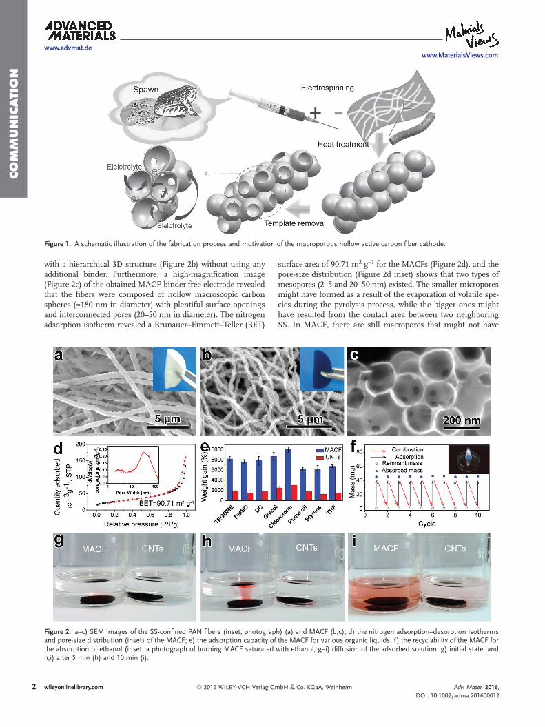
As shown in Figure 1, our synthesis strategy for MACFs was inspired and motivated by the toad spawning process as well as the favorable shape and structure of the eggs. First, the spawning process and the fibrous egg structure were imitated using an electrostatic spinning technique. Second, the colloidal shell-protected structure of the toad eggs was mimicked by embedding the spherical template (silica spheres (SS)) into a polymer matrix shell of polyacrylonitrile (PAN), where the size of SS, the ratio of the PAN to SS, and the conditions of the heat treatment were optimized. Briefly, SS were dispersed, and PAN was dissolved in dimethylformamide. Then, a glass syringe was filled with the as-prepared solution, which was electrospun to form the MACF precursor textile, followed by pre-oxidation and carbonization processes. Finally, the MACF textile was obtained after de-templating using hydrofluoric acid.
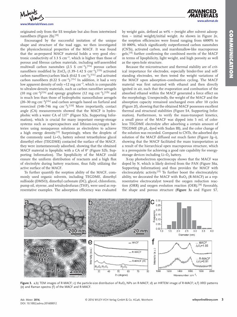
The morphology and the porous structure evolution of the MACFs were investigated by scanning electron microscopy (SEM). Interestingly, the SS were self-assembled and confined within the PAN fiber shell forming an interconnected and porous 3D textile (Figure 2a). After heat treatment and de-templating, the as-synthesized MACF nonwoven textile was self-standing
With the rapid development of consumer electronics, electric vehicles, and renewable energy storage, electrochemical energy-storage systems with high energy and rate densities are urgently required.[1] Theoretically, supercapacitors (SCs) possess high power densities, but they suffer from low energy densities. In contrast, lithium-ion batteries (LIBs) can deliver a higher energy density; however, for their applications as versatile power sources, significant enhancement in the energy and power den-sities of LIBs is necessary.[2] Therefore, the development of new electrode materials with higher capacities is highly desired to replace commercially used electrode materials. Unfortunately, the electrical conductivity of most candidate materials, including transition-metal oxides (TMOs) or transition-metal fluorides (TMFs), are intrinsically very low.[3] Even worse, the necessary addition of inactive, insulating, and swellable polymeric binders for electrode fabrication would inevitably hinder improvements in the energy density of LIBs.[4] Alternatively, going beyond LIB technology, rechargeable lithium–oxygen (Li–O2) batteries have been widely proposed as competitive candidates due to their extremely high theoretical energy density.[5] Unfortunately, because a complex solid–liquid–gas triphase region exists and the discharge product (lithium peroxide, Li2O2) is insoluble and insulating, the power density of Li–O2 batteries is still very poor.[6] Therefore, the development of a binder-free electrode is urgently required to simultaneously achieve rapid electronic and ionic conductivities, as well as mass and charge storage/transport; albeit, this goal is still very challenging.
Theoretically, due to their porous and fibrous structure, good electronic conductivity, and light weight, porous carbon nanofibers (CFs) can be employed as promising electrode mate-rials for LIBs and SCs, especially when decorated with active TMOs and/or TMFs.[7] However, when used as oxygen cath-odes in Li–O2 batteries, without being specially optimized, the existing porous CFs still have certain shortcomings. For example, their small pore size and volume cannot provide
Adv. Mater. 2016, DOI: 10.1002/adma.201600012
www.advmat.dewww.MaterialsViews.com
2 wileyonlinelibrary.com © 2016 WILEY-VCH Verlag GmbH & Co. KGaA, Weinheim
CO
MM
UN
ICATI
ON
with a hierarchical 3D structure (Figure 2b) without using any additional binder. Furthermore, a high-magnification image (Figure 2c) of the obtained MACF binder-free electrode revealed that the fibers were composed of hollow macroscopic carbon spheres (≈180 nm in diameter) with plentiful surface openings and interconnected pores (20–50 nm in diameter). The nitrogen adsorption isotherm revealed a Brunauer–Emmett–Teller (BET)
surface area of 90.71 m2 g−1 for the MACFs (Figure 2d), and the pore-size distribution (Figure 2d inset) shows that two types of mesopores (2–5 and 20–50 nm) existed. The smaller micropores might have formed as a result of the evaporation of volatile spe-cies during the pyrolysis process, while the bigger ones might have resulted from the contact area between two neighboring SS. In MACF, there are still macropores that might not have
Adv. Mater. 2016, DOI: 10.1002/adma.201600012
www.advmat.dewww.MaterialsViews.com
Figure 1. A schematic illustration of the fabrication process and motivation of the macroporous hollow active carbon fiber cathode.
Figure 2. a–c) SEM images of the SS-confined PAN fibers (inset, photograph) (a) and MACF (b,c); d) the nitrogen adsorption–desorption isotherms and pore-size distribution (inset) of the MACF; e) the adsorption capacity of the MACF for various organic liquids; f) the recyclability of the MACF for the absorption of ethanol (inset, a photograph of burning MACF saturated with ethanol, g–i) diffusion of the adsorbed solution: g) initial state, and h,i) after 5 min (h) and 10 min (i).
3wileyonlinelibrary.com© 2016 WILEY-VCH Verlag GmbH & Co. KGaA, Weinheim
CO
MM
UN
ICATIO
N
originated only from the SS template but also from intertwined nanofibers (Figure 2b).[10]
Encouraged by the successful imitation of the unique shape and structure of the toad eggs, we then investigated the physicochemical properties of the MACF. It was found that the as-prepared MACF material holds a very good elec-tronic conductivity of 3.3 S cm−1, which is higher than those of porous and fibrous carbon materials, including self-assembled multiwall carbon nanotubes (2.5 S cm−1),[11a] porous carbon nanofibers modified by ZnCl2 (1.39–1.42 S cm−1),[11b] activated carbon nanofibers/carbon black (0.62 S cm−1),[11c] and activated carbon nanofibers (0.22 S cm−1).[11c] In addition, it had a very low apparent density of only ≈12 mg cm−3, which is comparable to ultralow-density materials, such as carbon nanofiber aerogels (10 mg cm−3)[12a] and spongy graphene (12 mg cm−3),[12b] and is much less than those of hydrophobic nanocellulose aerogels (20–30 mg cm−3)[12c] and carbon aerogels based on furfural and resorcinol (148–746 mg cm−3).[12d] More importantly, contact angle (CA) measurements showed that the MACF is hydro-phobic with a water CA of 137° (Figure S2a, Supporting Infor-mation), which is crucial for many important energy-storage systems such as supercapacitors and lithium-ion/oxygen bat-teries using nonaqueous solutions as electrolytes to achieve a high energy density.[13] Surprisingly, when the droplets of the commonly used Li–O2 battery solvent tetraethylene glycol dimethyl ether (TEGDME) contacted the surface of the MACF, they were instantaneously adsorbed, showing that the obtained MACF material is lipophilic with a CA of 0° (Figure S2b, Sup-porting Information). The lipophilicity of the MACF could ensure the uniform distribution of reactants and a high flux of electrolyte during battery reactions, thus fully utilizing the active surface of the MACF.
To further quantify the sorption ability of the MACF, com-monly used organic solvents, including TEGDME, dimethyl sulfoxide (DMSO), dimethyl carbonate (DC), glycol, chloroform, pump oil, styrene, and tetrahydrofuran (THF), were used as rep-resentative examples. The adsorption efficiency was evaluated
by weight gain, defined as wt% = (weight after solvent adsorp-tion − initial weight)/initial weight. As shown in Figure 2e, the sorption efficiencies were found ranging from 6000% to 10 000%, which significantly outperformed carbon nanotubes (CNTs), activated carbon, and marshmallow-like macroporous gels,[14] further confirming the combined merits of the MACF in terms of lipophilicity, light weight, and high porosity as well as the open-hole structure.
Because the microstructure and thermal stability are of crit-ical importance for electrodes, especially binder-free and self-standing electrodes, we then tested the weight variations of the MACF upon adsorption–combustion cycling. The MACF material was first saturated with ethanol and then directly ignited in air, such that the evaporation and combustion of the absorbed ethanol within the MACF generated a force effect on the morphology. Unexpectedly, the weight of the MACF and the absorption capacity remained unchanged even after 10 cycles (Figure 2f), showing that the obtained MACF possesses excellent thermal and structural stabilities (Figure S4, Supporting Infor-mation). Furthermore, to verify the mass-transport kinetics, a small piece of the MACF was dipped into 5 mL of color-less TEGDME electrolyte after adsorbing a certain amount of TEGDME (20 μL, dyed with Sudan ΙΙΙ), and the color change of the solution was recorded. Compared to CNTs, the adsorbed dye solution of the MACF diffused out much faster (Figure 2g–i), showing that the MACF facilitated the mass transportation as a result of the hierarchical open macroporous structure, which is a prerequisite for achieving a good rate capability for energy-storage devices including Li–O2 battery.
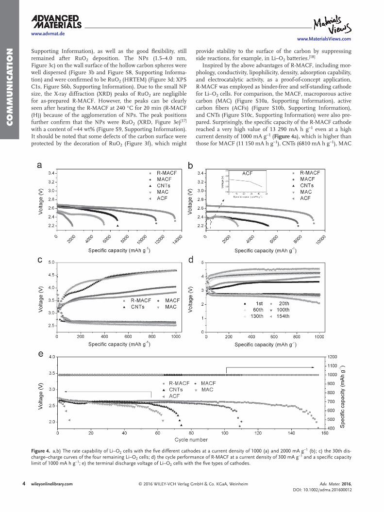
X-ray photoelectron spectroscopy shows that the MACF was doped by N, which is likely derived from the PAN (Figure S6a, Supporting Information) and thus provides the MACF with electrocatalytic activity.[15] To further boost the electrocatalytic ability, we decorated the MACF with RuO2 (R-MACF) as a rep-resentative electrocatalyst toward the oxygen reduction reac-tion (ORR) and oxygen evolution reaction (OER).[16] Favorably, the shape and porous structure (Figure 3a and Figure S7,
Adv. Mater. 2016, DOI: 10.1002/adma.201600012
www.advmat.dewww.MaterialsViews.com
Figure 3. a,b) TEM images of R-MACF; c) the particle-size distribution of RuO2 NPs on R-MACF; d) an HRTEM image of R-MACF; e,f) XRD patterns (e) and Raman spectra (f) of the MACF and R-MACF.
4 wileyonlinelibrary.com © 2016 WILEY-VCH Verlag GmbH & Co. KGaA, Weinheim
CO
MM
UN
ICATI
ON Supporting Information), as well as the good flexibility, still
remained after RuO2 deposition. The NPs (1.5–4.0 nm, Figure 3c) on the wall surface of the hollow carbon spheres were well dispersed (Figure 3b and Figure S8, Supporting Informa-tion) and were confirmed to be RuO2 (HRTEM) (Figure 3d; XPS C1s, Figure S6b, Supporting Information). Due to the small NP size, the X-ray diffraction (XRD) peaks of RuO2 are negligible for as-prepared R-MACF. However, the peaks can be clearly seen after heating the R-MACF at 240 °C for 20 min (R-MACF (H)) because of the agglomeration of NPs. The peak positions further confirm that the NPs were RuO2 (XRD, Figure 3e)[17] with a content of ≈44 wt% (Figure S9, Supporting Information). It should be noted that some defects of the carbon surface were protected by the decoration of RuO2 (Figure 3f), which might
provide stability to the surface of the carbon by suppressing side reactions, for example, in Li–O2 batteries.[18]
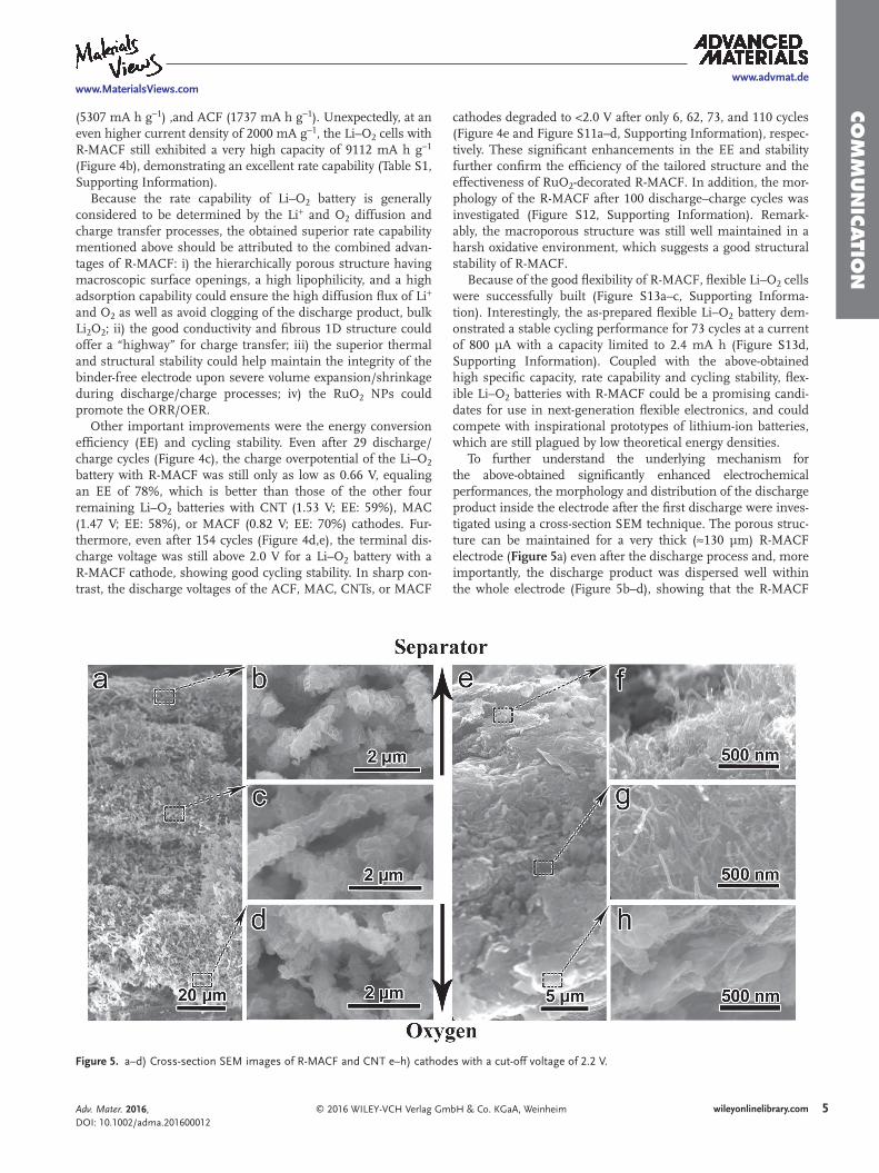
Inspired by the above advantages of R-MACF, including mor-phology, conductivity, lipophilicity, density, adsorption capability, and electrocatalytic activity, as a proof-of-concept application, R-MACF was employed as binder-free and self-standing cathode for Li–O2 cells. For comparison, the MACF, macroporous active carbon (MAC) (Figure S10a, Supporting Information), active carbon fibers (ACFs) (Figure S10b, Supporting Information), and CNTs (Figure S10c, Supporting Information) were also pre-pared. Surprisingly, the specific capacity of the R-MACF cathode reached a very high value of 13 290 mA h g−1 even at a high current density of 1000 mA g−1 (Figure 4a), which is higher than those for MACF (11 150 mA h g−1), CNTs (6810 mA h g−1), MAC
Adv. Mater. 2016, DOI: 10.1002/adma.201600012
www.advmat.dewww.MaterialsViews.com
Figure 4. a,b) The rate capability of Li–O2 cells with the five different cathodes at a current density of 1000 (a) and 2000 mA g−1 (b); c) the 30th dis-charge–charge curves of the four remaining Li–O2 cells; d) the cycle performance of R-MACF at a current density of 300 mA g−1 and a specific capacity limit of 1000 mA h g−1; e) the terminal discharge voltage of Li–O2 cells with the five types of cathodes.
5wileyonlinelibrary.com© 2016 WILEY-VCH Verlag GmbH & Co. KGaA, Weinheim
CO
MM
UN
ICATIO
N
Adv. Mater. 2016, DOI: 10.1002/adma.201600012
www.advmat.dewww.MaterialsViews.com
(5307 mA h g−1) ,and ACF (1737 mA h g−1). Unexpectedly, at an even higher current density of 2000 mA g−1, the Li–O2 cells with R-MACF still exhibited a very high capacity of 9112 mA h g−1 (Figure 4b), demonstrating an excellent rate capability (Table S1, Supporting Information).
Because the rate capability of Li–O2 battery is generally considered to be determined by the Li+ and O2 diffusion and charge transfer processes, the obtained superior rate capability mentioned above should be attributed to the combined advan-tages of R-MACF: i) the hierarchically porous structure having macroscopic surface openings, a high lipophilicity, and a high adsorption capability could ensure the high diffusion flux of Li+ and O2 as well as avoid clogging of the discharge product, bulk Li2O2; ii) the good conductivity and fibrous 1D structure could offer a “highway” for charge transfer; iii) the superior thermal and structural stability could help maintain the integrity of the binder-free electrode upon severe volume expansion/shrinkage during discharge/charge processes; iv) the RuO2 NPs could promote the ORR/OER.
Other important improvements were the energy conversion efficiency (EE) and cycling stability. Even after 29 discharge/charge cycles (Figure 4c), the charge overpotential of the Li–O2 battery with R-MACF was still only as low as 0.66 V, equaling an EE of 78%, which is better than those of the other four remaining Li–O2 batteries with CNT (1.53 V; EE: 59%), MAC (1.47 V; EE: 58%), or MACF (0.82 V; EE: 70%) cathodes. Fur-thermore, even after 154 cycles (Figure 4d,e), the terminal dis-charge voltage was still above 2.0 V for a Li–O2 battery with a R-MACF cathode, showing good cycling stability. In sharp con-trast, the discharge voltages of the ACF, MAC, CNTs, or MACF
cathodes degraded to <2.0 V after only 6, 62, 73, and 110 cycles (Figure 4e and Figure S11a–d, Supporting Information), respec-tively. These significant enhancements in the EE and stability further confirm the efficiency of the tailored structure and the effectiveness of RuO2-decorated R-MACF. In addition, the mor-phology of the R-MACF after 100 discharge–charge cycles was investigated (Figure S12, Supporting Information). Remark-ably, the macroporous structure was still well maintained in a harsh oxidative environment, which suggests a good structural stability of R-MACF.
Because of the good flexibility of R-MACF, flexible Li–O2 cells were successfully built (Figure S13a–c, Supporting Informa-tion). Interestingly, the as-prepared flexible Li–O2 battery dem-onstrated a stable cycling performance for 73 cycles at a current of 800 μA with a capacity limited to 2.4 mA h (Figure S13d, Supporting Information). Coupled with the above-obtained high specific capacity, rate capability and cycling stability, flex-ible Li–O2 batteries with R-MACF could be a promising candi-dates for use in next-generation flexible electronics, and could compete with inspirational prototypes of lithium-ion batteries, which are still plagued by low theoretical energy densities.
To further understand the underlying mechanism for the above-obtained significantly enhanced electrochemical performances, the morphology and distribution of the discharge product inside the electrode after the first discharge were inves-tigated using a cross-section SEM technique. The porous struc-ture can be maintained for a very thick (≈130 μm) R-MACF electrode (Figure 5a) even after the discharge process and, more importantly, the discharge product was dispersed well within the whole electrode (Figure 5b–d), showing that the R-MACF
Figure 5. a–d) Cross-section SEM images of R-MACF and CNT e–h) cathodes with a cut-off voltage of 2.2 V.
6 wileyonlinelibrary.com © 2016 WILEY-VCH Verlag GmbH & Co. KGaA, Weinheim
CO
MM
UN
ICATI
ON
Adv. Mater. 2016, DOI: 10.1002/adma.201600012
www.advmat.dewww.MaterialsViews.com
can offer adequate and uniform solid–liquid–gas triphase regions due to its unique porous structure and the decoration with evenly dispersed RuO2 NPs, which improves the specific capacity, rate capability, EE and cycle stability. On the contrary, for the conventional CNTs electrode (which is much thinner, ≈35 μm), the discharge product only aggregated on its surface and seriously blocked the pores and channels (Figure 5f–h and Figure S14, Supporting Information), inevitably resulting in the insufficient utilization of the CNT electrode and the poor elec-trochemical performances.
In summary, to meet the challenges of simultaneously achieving rapid electronic and ionic conductivities and favorable mass storage/transport for the fundamental electrochemical energy-storage processes, a binder-free and self-standing MACF electrode was designed and fabricated. The fabrication pro-cess involved a facile and scalable method combining electro-spinning and template techniques to imitate the golden-toad spawning process as well as the favorable shape and structure of the eggs. The obtained MACF electrode exhibited suitable char-acteristics including high electrical conductivity, low cost, and density, superior mechanical and thermal stabilities and excel-lent mass adsorption and transport properties. Unexpectedly, as a proof-of-concept application, the electrode enhanced the Li–O2 battery, demonstrating superior electrochemical performance, including a high specific capacity, a good cycling stability, and an especially excellent rate capability. Furthermore, resulting from the good flexibility of the electrode, a flexible Li–O2 cell was suc-cessfully built, which provides new hope for flexible electronics, which are plagued by the low theoretical energy density of the available flexible power sources. The MACF-boosted advan-tages, as well as the scientific understanding, could be extended to other storage/conversion systems wherein fast ion/electron and mass storage/transportation, as well as mechanical and thermal robustness, are highly required.
Supporting InformationSupporting Information is available from the Wiley Online Library or from the author.
AcknowledgementsThis work was financially supported by 100 Talents Program of the Chinese Academy of Sciences, National Program on Key Basic Research Project of China (2012CB215500 and 2014CB932300), National Natural Science Foundation of China (Grant No. 51472232, 21422108 and 51301160), Strategic Priority Research Program of Chinese Academy of Sciences (Grant No. XDA09010404), and Jilin Province Science and Technology Development Program (Grant No. 20160101289JC).
Received: January 3, 2016Revised: May 3, 2016
Published online:
[1] a) S. W. Lee, N. Yabuuchi, B. M. Gallant, S. Chen, B. S. Kim, P. T. Hammond, Y. Shao-Horn, Nat. Nanotechnol. 2010, 5, 531; b) J. Yan, A. Sumboja, E. Khoo, P. S. Lee, Adv. Mater. 2011, 23,
746; c) H. Wang, Y. Yang, Y. Liang, G. Zheng, Y. Li, Y. Cui, H. Dai, Energy Environ. Sci. 2012, 5, 7931; d) B. Sun, X. Huang, S. Chen, P. Munroe, G. Wang, Nano Lett. 2014, 14, 3145.
[2] a) P. Simon, Y. Gogotsi, Nat. Mater. 2008, 7, 845; b) L. M. Suo, Y. S. Hu, H. Li, M. Armand, L. Q. Chen, Nat. Commun. 2013, 4, 1481; c) D. Yang, Z. Lu, X. Rui, X. Huang, H. Li, J. Zhu, W. Zhang, Y. M. Lam, H. H. Hng, H. Zhang, Q. Yan, Angew. Chem., Int. Ed. 2014, 53, 9352; d) J. Liu, M. Banis, Q. Sun, A. Lushington, R. Li, T.-K Sham, X. Sun, Adv. Mater. 2014, 26, 6472; e) X. Y. Yu, H. B. Wu, L. Yu, F. X. Ma, X. W. Lou, Angew. Chem., Int. Ed. 2015, 54, 4001; f) X. Lu, L. Zhao, X. Q. He, R. J. Xiao, L. Gu, Y.-S. Hu, H. Li, Z. X. Wang, X. F. Duan, L. Q. Chen, J. Maier, Y. Ikuhara, Adv. Mater. 2012, 24, 3233.
[3] a) P. Poizot, S. Laruelle, S. Grugeon, L. Dupont, J.-M. Tarascon, Nature 2000, 407, 496; b) H. Wang, L.-F. Cui, Y. Yang, H. S. Casalongue, J. T. Robinson, Y. Liang, Y. Cui, H. Dai, J. Am. Chem. Soc. 2010, 132, 13978; c) D.-L. Ma, Z.-Y. Cao, H.-G. Wang, X.-L. Huang, L.-M. Wang, X.-B. Zhang, Energy Environ. Sci. 2012, 5, 8538; d) X. Huang, X. Y. Qi, F. Boey, H. Zhang, Chem. Soc. Rev. 2012, 41, 666; e) J. Wang, J. Yang, Y. Tang, J. Liu, Y. Zhang, G. Liang, M. Gauthier, Y. K. Chen, M. Banis, X. Li, R. Li, J. Wang, T.-K. Sham, X. Sun, Nat. Commun. 2014, 5, 3145; f) J. Liang, X. Y. Yu, H. Zhou, H. B. Wu, S. J. Ding, X. W. Lou, Angew. Chem., Int. Ed. 2014, 53, 12803.
[4] a) C. Ban, Z. Wu, D. T. Gillaspie, L. Chen, Y. Yan, J. L. Blackburn, A. C. Dillon, Adv. Mater. 2010, 22, E145; b) S. Luo, K. Wang, J. Wang, K. Jiang, Q. Li, S. Fan, Adv. Mater. 2012, 24, 2294.
[5] a) K. M. Abraham, Z. Jiang, J. Electrochem. Soc. 1996, 143, 1; b) P. G. Bruce, S. A. Freunberger, L. J. Hardwick, J.-M. Tarascon, Nat. Mater. 2012, 11, 19; c) R. Black, S. H. Oh, J.-H. Lee, T. Yim, B. Adams, L. F. Nazar, J. Am. Chem. Soc. 2012, 134, 2902.
[6] Y. Hu, X. Sun, J. Mater. Chem. A 2014, 2, 10712.[7] a) C. Kim, Y. I. Jeong, B. T. N. Ngoc, K. S. Yang, M. Kojima, Y. A. Kim,
M. Endo, J.-W. Lee, Small 2007, 3, 91; b) D. Yu, C. Chen, S. Xie, Y. Liu, K. Park, X. Zhou, Q. Zhang, J. Li, G. Cao, Energy Environ. Sci. 2011, 4, 858; c) M. Wang, Z.-H. Huang, Y. Bai, F. Kang, M. Inagaki, Curr. Org. Chem. 2013, 17, 1434; d) G. Zhang, X. W. Lou, Sci. Rep. 2013, 3, 1470; e) H.-I. Joh, H. K. Song, C.-H. Lee, J.-M. Yun, S. M. Jo, S. Lee, S.-I. Na, A.-T. Chien, S. Kumar, Carbon 2014, 70, 308.
[8] a) P. Andrei, J. P. Zheng, M. Hendrickson, E. J. Plich, J. Electro-chem. Soc. 2010, 157, A1287; b) R. R. Mitchell, B. M. Gallant, C. V. Thompson, S.-H. Yang, Energy Environ. Sci. 2011, 4, 2952; c) V. Viswanathan, K. S. Thygesen, J. S. Hummelshøj, J. K. Nørskov, G. Girishkumar, B. D. McCloskey, A. C. Luntz, J. Chem. Phys. 2011, 135, 214704; d) J. Hou, M. Yang, M. W. Ellis, R. B. Moore, B. Yi, Phys. Chem. Chem. Phys. 2012, 14, 13487.
[9] J.-J. Xu, Z.-L. Wang, D. Xu, L.-L. Zhang, X.-B. Zhang, Nat. Commun. 2013, 4, 2438.
[10] Z.-Y. Wu, C. Li, H.-W. Liang, Y.-N. Zhang, X. Wang, J.-F. Chen, S.-H. Yu, Sci. Rep. 2014, 4, 4079.
[11] a) M. C. Gutiérrez, M. J. Hortigüela, J. M. Amarilla, R. Jiménez, M. L. Ferrer, F. D. Monte, J. Phys. Chem. C 2007, 111, 5557; b) C. Kim, B. T. N. Ngoc, K. S. Yang, M. Kojima, Y. A. Kim, Y. J. Kim, M. Endo, S. C. Yang, Adv. Mater. 2007, 19, 2341; c) G. Wang, Q. Dong, Z. Ling, C. Pan, C. Yu, J. Qiu, J. Mater. Chem. 2012, 22, 21819.
[12] a) Z.-Y. Wu, C. Li, H.-W. Liang, Y.-N. Zhang, X. Wang, J.-F. Chen, S.-H. Yu, Sci. Rep. 2014, 4, 4079; b) H. Bi, X. Xie, K. Yin, Y. Zhou, S. Wan, L. He, F. Xu, F. Banhart, L. Sun, R. S. Ruoff, Adv. Funct. Mater. 2012, 22, 4421; c) J. T. Korhonen, M. Kettunen, R. H. A. Ras, O. Ikkala, ACS Appl. Mater. Interfaces 2011, 3, 1813; d) R. Fu, B. Zheng, J. Liu, M. S. Dresselhaus, G. Dresselhaus,
7wileyonlinelibrary.com© 2016 WILEY-VCH Verlag GmbH & Co. KGaA, Weinheim
CO
MM
UN
ICATIO
N
Adv. Mater. 2016, DOI: 10.1002/adma.201600012
www.advmat.dewww.MaterialsViews.com
J. H. Satcher Jr., T. F. Baumann, Adv. Funct. Mater. 2003, 13, 558.
[13] M. M. O. Thotiyl, S. A. Freunberger, Z. Peng, P. G. Bruce, J. Am. Chem. Soc. 2013, 135, 494.
[14] a) M. A. Lillo-Ródenas, D. Cazorla-Amorós, A. Linares-Solano, Carbon 2005, 43, 1758; b) G. Hayase, K. Kanamori, M. Fukuchi, H. Kaji, K. Nakanishi, Angew. Chem., Int. Ed. 2013, 52, 1986.
[15] G. Wu, N. H. Mack, W. Gao, S. Ma, R. Zhong, J. Han, J. K. Baldwin, P. Zelenay, ACS Nano 2012, 6, 9764.
[16] a) E. Yilmaz, C. Yogi, K. Yamanaka, T. Ohta, H. R. Byon, Nano Lett. 2013, 13, 4679; b) Z. Jian, P. Liu, F. Li, P. He, X. Guo, M. Chen, H. Zhou, Angew. Chem., Int. Ed. 2014, 53, 442.
[17] Z. Sun, Z. Liu, B. Han, S. Miao, J. Du, Z. Miao, Carbon 2006, 44, 888.
[18] D. M. Itkis, D. A. Semenenko, E. Y. Kataev, A. I. Belova, V. S. Neudachina, A. P. Sirotina, M. Hävecker, D. Teschner, A. Knop-Gericke, P. Dudin, A. Barinov, E. A. Goodilin, Y. Shao-Horn, L. V. Yashina, Nano Lett. 2013, 13, 4697.