
Machine / Setting Data Explanations Overview SINUMERIK ... · SINUMERIK 802D sl Lists Machine /...
222
Valid for Control system Software version SINUMERIK 802D sl 1 02.06 Edition 6FC5397−5CP10−0BA0 SINUMERIK 802D sl Lists Machine / Setting Data Explanations 1 Machine Data Overview 2 Setting Data Overview 3 Machine Data Description 4 Setting Data Description 5 Interface Signals 6 PLC User Interface - 7 SINAMICS Parameters 8
Transcript of Machine / Setting Data Explanations Overview SINUMERIK ... · SINUMERIK 802D sl Lists Machine /...

Valid for
Control system Software versionSINUMERIK 802D sl 1
02.06 Edition6FC5397−5CP10−0BA0
SINUMERIK 802D sl
Lists
Machine / Setting DataExplanations 1Machine DataOverview 2
Setting DataOverview 3
Machine DataDescription 4
Setting DataDescription 5
Interface Signals 6
PLC User Interface - 7
SINAMICS Parameters 8

Siemens AGAutomation and DrivesPostfach 48 4890437 NÜRNBERGDEUTSCHLAND
6FC5397−5CP10−0BA002/2006 Edition
Copyright � Siemens AG 2006.Subject to change without priornotice
Safety-related informationThis manual contains important information related to your personal safety and the protection ofequipment. The notices referring to your personal safety are highlighted in the manual by a triangularsafety alert symbol, notices referring to property damage only have no safety alert symbol. Thesenotices shown below are graded according to the degree of danger:
!Danger
indicates that death or severe personal injury will result if proper precautions are not taken.
!Warning
indicates that death or severe personal injury may result if proper precautions are not taken.
!Caution
with a safety alert symbol, indicates that minor personal injury can result if proper precautions are nottaken.
Caution
without a safety alert symbol, indicates that property damage can result if proper precautions are nottaken.
Notice
indicates that an undesirable event or state may arise if the relevant note is not observed.
If more than one degree of danger is present, the warning notice representing the highest degree ofdanger will be used. A notice warning of injury to persons with a warning symbol may also include awarning relating to property damage.
Qualified personnelThe device/system may only be set up and used in conjunction with this documentation.Commissioning and operation of a device/system may only be performed by qualified personnel.Qualified persons as far as the safety instructions given in this documentation are concerned arethose who have the necessary authorization to commission, ground and identify equipment, systemsand circuits in accordance with the relevant safety standards.
Use as prescribedNote the following:
!Warning
This device and its components may only be used for the applications described in the catalog or inthe technical descriptions, and only in combination with third-party devices and components whichhave been approved or recommended by Siemens. This product can only function correctly andsafely if it is transported, stored, set up, and installed correctly, and operated and maintained asrecommended.
TrademarksAll designations with the trademark symbol ® are registered trademarks of Siemens AG. Otherdesignations in this documentation may be trademarks whose use by third parties for their ownpurposes may infringe the rights of the owner.
Disclaimer of liabilityWe have checked the contents of this manual for agreement with the hardware and softwaredescribed. Since discrepancies cannot be precluded entirely, we cannot guarantee full agreement.The information given in this publication is reviewed at regular intervals and any corrections thatmight be necessary are made in the subsequent editions.

iii SINUMERIK 802D sl Lists (LIS), 02/06 Edition6FC5397−5CP10−0BA0
Preface
SINUMERIK Documentation
The SINUMERIK Documentation is organized in 3 levels:
� General Documentation:
� User Documentation
� Manufacturer/Service Documentation:
A monthly overview of publications with specification of the available languages can be foundon the Internet at:http://www.siemens.com/motioncontrolFollow the menu items ”Support”/”Technical Documentation”/”Overview of Publications”.
The Internet edition of DOConCD − DOConWEB − can be found at:http://www.automation.siemens.com/doconweb
Information of our training offer and answers to frequently asked questions (”FAQs”) can befound on the Internet at: http://www.siemens.com/motioncontrol and there under the menu option ”Support”.
Target group
The present publication is aimed at planning engineers, programmers and start−up engi-neers.
Utility value
The present Lists Manual provides knowledge in respect of parameters and their effects onthe system.
Standard scope
The present documentation describes the functionality of the standard scope. Any amend-ments made by the machine manufacturer are documented by the machine manufacturer.
Other functions not described in this documentation can possibly also be performed on thecontrol system. However, the customer is not entitled to demand these functions when thenew equipment is supplied or servicing is carried out.
For reasons of clarity, this documentation does not contain all detailed information on all ty-pes of the product and can thus not consider any conceivable case of installation, operationand maintenance.
Technical Support
If you have any questions, do not hesitate to call our hotline:

Preface
ivSINUMERIK 802D sl Lists (LIS), 02/06 Edition
6FC5397−5CP10−0BA0
Time zones Europe and Africa
A&D Technical SupportTel.: +49 (0) 180 / 5050 − 222Fax: +49 (0) 180 / 5050 − 223Internet: http://www.siemens.com/automation/support−requestE−mail: mailto:[email protected]
Time zones Asia and Australia
A&D Technical SupportTel.: +86 1064 719 990Fax: +86 1064 747 474Internet: http://www.siemens.com/automation/support−requestE−mail: mailto:[email protected]
Time zone America
A&D Technical SupportTel.: +1 423 262 2522Fax: +1 423 262 2289Internet: http://www.siemens.com/automation/support−requestE−mail: mailto:[email protected]
Questions regarding the Manual
If you have any questions (suggestions, corrections) regarding the Documentation, pleasesend a fax to the following number or an e−mail to the following address:
Fax: +49 (0) 9131 / 98 − 63315E−mail: mailto:[email protected] form: see return fax form at the end of this publication
Internet address for SINUMERIK
http://www.siemens.com/sinumerik
EU Declaration of Conformity
The EU Declaration of Conformity in respect of the EMC Guideline can be obtained
� on the Internet:http://www.ad.siemens.de/csinfounder the product order number 15257461
� and from the appropriate regional office of the business area A&D MC of Siemens AG.

Table of Contents
v SINUMERIK 802D sl Lists (LIS), 02/06 Edition6FC5397−5CP10−0BA0
Table of Contents
1 Machine and Setting Data − Explanations 1-17 . . . . . . . . . . . . . . . . . . . . . . . . . . . . . . . . . . . . . .
1.1 Specifications in the list 1-17 . . . . . . . . . . . . . . . . . . . . . . . . . . . . . . . . . . . . . . . . . . . . . . . . . . . . . . . .
1.2 Overview of the machine and setting data areas 1-22 . . . . . . . . . . . . . . . . . . . . . . . . . . . . . . . . . . .
2 List of Machine Data 2-23 . . . . . . . . . . . . . . . . . . . . . . . . . . . . . . . . . . . . . . . . . . . . . . . . . . . . . . . . .
2.1 Display machine data 2-23 . . . . . . . . . . . . . . . . . . . . . . . . . . . . . . . . . . . . . . . . . . . . . . . . . . . . . . . . . .
2.2 General machine data 2-29 . . . . . . . . . . . . . . . . . . . . . . . . . . . . . . . . . . . . . . . . . . . . . . . . . . . . . . . .
2.3 Channel−specific machine data 2-38 . . . . . . . . . . . . . . . . . . . . . . . . . . . . . . . . . . . . . . . . . . . . . . . .
2.4 Axis−specific machine data 2-49 . . . . . . . . . . . . . . . . . . . . . . . . . . . . . . . . . . . . . . . . . . . . . . . . . . . .
3 Setting Data − Overview 3-65 . . . . . . . . . . . . . . . . . . . . . . . . . . . . . . . . . . . . . . . . . . . . . . . . . . . . . . .
3.1 Setting data 3-65 . . . . . . . . . . . . . . . . . . . . . . . . . . . . . . . . . . . . . . . . . . . . . . . . . . . . . . . . . . . . . . . . . .
3.2 Channel−specific setting data 3-67 . . . . . . . . . . . . . . . . . . . . . . . . . . . . . . . . . . . . . . . . . . . . . . . . . . .
3.3 Axis−specific setting data 3-71 . . . . . . . . . . . . . . . . . . . . . . . . . . . . . . . . . . . . . . . . . . . . . . . . . . . . . .
4 Machine Data − Description 4-75 . . . . . . . . . . . . . . . . . . . . . . . . . . . . . . . . . . . . . . . . . . . . . . . . . . .
4.1 Display machine data 4-75 . . . . . . . . . . . . . . . . . . . . . . . . . . . . . . . . . . . . . . . . . . . . . . . . . . . . . . . . . .
4.2 General machine data 4-78 . . . . . . . . . . . . . . . . . . . . . . . . . . . . . . . . . . . . . . . . . . . . . . . . . . . . . . . . .
4.3 Channel-specific machine data 4-82 . . . . . . . . . . . . . . . . . . . . . . . . . . . . . . . . . . . . . . . . . . . . . . . . . .
4.4 Axis-specific machine data 4-90 . . . . . . . . . . . . . . . . . . . . . . . . . . . . . . . . . . . . . . . . . . . . . . . . . . . . .
5 Setting Data − Description 5-119 . . . . . . . . . . . . . . . . . . . . . . . . . . . . . . . . . . . . . . . . . . . . . . . . . . . .
5.1 General setting data 5-119 . . . . . . . . . . . . . . . . . . . . . . . . . . . . . . . . . . . . . . . . . . . . . . . . . . . . . . . . . . .
5.2 Channel-specific setting data 5-121 . . . . . . . . . . . . . . . . . . . . . . . . . . . . . . . . . . . . . . . . . . . . . . . . . . .
5.3 Spindle-specific setting data 5-123 . . . . . . . . . . . . . . . . . . . . . . . . . . . . . . . . . . . . . . . . . . . . . . . . . . . .
6 Interface Signals 6-127 . . . . . . . . . . . . . . . . . . . . . . . . . . . . . . . . . . . . . . . . . . . . . . . . . . . . . . . . . . . . .
6.1 General 6-127 . . . . . . . . . . . . . . . . . . . . . . . . . . . . . . . . . . . . . . . . . . . . . . . . . . . . . . . . . . . . . . . . . . . . . .
6.2 Signals from/to HMI 6-129 . . . . . . . . . . . . . . . . . . . . . . . . . . . . . . . . . . . . . . . . . . . . . . . . . . . . . . . . . . . 6.2.1 Program−control signals from HMI 6-129 . . . . . . . . . . . . . . . . . . . . . . . . . . . . . . . . . . . . . . . . . . . . . . . 6.2.2 Signals from HMI 6-130 . . . . . . . . . . . . . . . . . . . . . . . . . . . . . . . . . . . . . . . . . . . . . . . . . . . . . . . . . . . . . . 6.2.3 Signals from operator panel 6-131 . . . . . . . . . . . . . . . . . . . . . . . . . . . . . . . . . . . . . . . . . . . . . . . . . . . . 6.2.4 General selection/status signals from HMI 6-131 . . . . . . . . . . . . . . . . . . . . . . . . . . . . . . . . . . . . . . . . 6.2.5 General selection/status signals to HMI 6-132 . . . . . . . . . . . . . . . . . . . . . . . . . . . . . . . . . . . . . . . . . .
6.3 Auxiliary function transfer from NC channel 6-134 . . . . . . . . . . . . . . . . . . . . . . . . . . . . . . . . . . . . . . .
6.4 NCK signals 6-137 . . . . . . . . . . . . . . . . . . . . . . . . . . . . . . . . . . . . . . . . . . . . . . . . . . . . . . . . . . . . . . . . . . 6.4.1 General signals to NCK 6-137 . . . . . . . . . . . . . . . . . . . . . . . . . . . . . . . . . . . . . . . . . . . . . . . . . . . . . . . . 6.4.2 General signals from NCK 6-138 . . . . . . . . . . . . . . . . . . . . . . . . . . . . . . . . . . . . . . . . . . . . . . . . . . . . . .
6.5 Mode signals 6-140 . . . . . . . . . . . . . . . . . . . . . . . . . . . . . . . . . . . . . . . . . . . . . . . . . . . . . . . . . . . . . . . .
6.6 Channel-specific signals 6-143 . . . . . . . . . . . . . . . . . . . . . . . . . . . . . . . . . . . . . . . . . . . . . . . . . . . . . . . 6.6.1 Signals to channel 6-143 . . . . . . . . . . . . . . . . . . . . . . . . . . . . . . . . . . . . . . . . . . . . . . . . . . . . . . . . . . . . 6.6.2 Signals from the channel 6-154 . . . . . . . . . . . . . . . . . . . . . . . . . . . . . . . . . . . . . . . . . . . . . . . . . . . . . . .
6.7 Axis/spindle-specific signals 6-162 . . . . . . . . . . . . . . . . . . . . . . . . . . . . . . . . . . . . . . . . . . . . . . . . . . . . 6.7.1 Transferred axis−specific M and S functions 6-162 . . . . . . . . . . . . . . . . . . . . . . . . . . . . . . . . . . . . . . 6.7.2 Signals to axis/spindle 6-163 . . . . . . . . . . . . . . . . . . . . . . . . . . . . . . . . . . . . . . . . . . . . . . . . . . . . . . . . . 6.7.3 Signals from axis/spindle 6-174 . . . . . . . . . . . . . . . . . . . . . . . . . . . . . . . . . . . . . . . . . . . . . . . . . . . . . . .

Table of Contents
viSINUMERIK 802D sl Lists (LIS), 02/06 Edition
6FC5397−5CP10−0BA0
6.8 Tool management functions from NC channel 6-182 . . . . . . . . . . . . . . . . . . . . . . . . . . . . . . . . . . . . .
7 PLC User Interface 7-183 . . . . . . . . . . . . . . . . . . . . . . . . . . . . . . . . . . . . . . . . . . . . . . . . . . . . . . . . . . . .
7.1 Address ranges 7-183 . . . . . . . . . . . . . . . . . . . . . . . . . . . . . . . . . . . . . . . . . . . . . . . . . . . . . . . . . . . . . . .
7.2 User data 7-185 . . . . . . . . . . . . . . . . . . . . . . . . . . . . . . . . . . . . . . . . . . . . . . . . . . . . . . . . . . . . . . . . . . . . 7.2.1 User data 1 7-185 . . . . . . . . . . . . . . . . . . . . . . . . . . . . . . . . . . . . . . . . . . . . . . . . . . . . . . . . . . . . . . . . . . 7.2.2 User data2 7-185 . . . . . . . . . . . . . . . . . . . . . . . . . . . . . . . . . . . . . . . . . . . . . . . . . . . . . . . . . . . . . . . . . . . 7.2.3 Signals from MCP (connected to the MCPA module) 7-185 . . . . . . . . . . . . . . . . . . . . . . . . . . . . . . . 7.2.4 Signals to MCP (connected to the MCPA module) 7-186 . . . . . . . . . . . . . . . . . . . . . . . . . . . . . . . . . . 7.2.5 Reading/writing NC data: Job [F20.6] 7-186 . . . . . . . . . . . . . . . . . . . . . . . . . . . . . . . . . . . . . . . . . . . . 7.2.6 Read/write NC data: Result [F20.6] 7-186 . . . . . . . . . . . . . . . . . . . . . . . . . . . . . . . . . . . . . . . . . . . . . .
7.3 Retentive data area 7-187 . . . . . . . . . . . . . . . . . . . . . . . . . . . . . . . . . . . . . . . . . . . . . . . . . . . . . . . . . . .
7.4 User alarm 7-188 . . . . . . . . . . . . . . . . . . . . . . . . . . . . . . . . . . . . . . . . . . . . . . . . . . . . . . . . . . . . . . . . . . . 7.4.1 User alarm: Activation 7-188 . . . . . . . . . . . . . . . . . . . . . . . . . . . . . . . . . . . . . . . . . . . . . . . . . . . . . . . . . 7.4.2 Variable for alarm 7-188 . . . . . . . . . . . . . . . . . . . . . . . . . . . . . . . . . . . . . . . . . . . . . . . . . . . . . . . . . . . . . 7.4.3 Active alarm reaction 7-189 . . . . . . . . . . . . . . . . . . . . . . . . . . . . . . . . . . . . . . . . . . . . . . . . . . . . . . . . . .
7.5 Signals from/to HMI 7-189 . . . . . . . . . . . . . . . . . . . . . . . . . . . . . . . . . . . . . . . . . . . . . . . . . . . . . . . . . . . 7.5.1 Program control signals from HMI (retentive area) 7-189 . . . . . . . . . . . . . . . . . . . . . . . . . . . . . . . . . . 7.5.2 Program selection from PLC (retentive area) 7-190 . . . . . . . . . . . . . . . . . . . . . . . . . . . . . . . . . . . . . . 7.5.3 Checkback signal ”Program selection from HMI (retentive area) 7-190 . . . . . . . . . . . . . . . . . . . . . . 7.5.4 Signals from HMI 7-190 . . . . . . . . . . . . . . . . . . . . . . . . . . . . . . . . . . . . . . . . . . . . . . . . . . . . . . . . . . . . . . 7.5.5 Signals from PLC 7-191 . . . . . . . . . . . . . . . . . . . . . . . . . . . . . . . . . . . . . . . . . . . . . . . . . . . . . . . . . . . . . 7.5.6 Signals from operator panel (retentive area) 7-191 . . . . . . . . . . . . . . . . . . . . . . . . . . . . . . . . . . . . . . . 7.5.7 General selection/status signals from HMI (retentive area) 7-191 . . . . . . . . . . . . . . . . . . . . . . . . . . 7.5.8 General selection/status signals to HMI (retentive area) 7-192 . . . . . . . . . . . . . . . . . . . . . . . . . . . . .
7.6 Auxiliary function transfer from NC channel 7-193 . . . . . . . . . . . . . . . . . . . . . . . . . . . . . . . . . . . . . . . 7.6.1 Decoded M signals: (M0−M99) 7-194 . . . . . . . . . . . . . . . . . . . . . . . . . . . . . . . . . . . . . . . . . . . . . . . . . . 7.6.2 Transferred T functions 7-194 . . . . . . . . . . . . . . . . . . . . . . . . . . . . . . . . . . . . . . . . . . . . . . . . . . . . . . . . 7.6.3 Transferred M functions 7-195 . . . . . . . . . . . . . . . . . . . . . . . . . . . . . . . . . . . . . . . . . . . . . . . . . . . . . . . . 7.6.4 Transferred S functions 7-195 . . . . . . . . . . . . . . . . . . . . . . . . . . . . . . . . . . . . . . . . . . . . . . . . . . . . . . . . 7.6.5 Transferred D functions 7-195 . . . . . . . . . . . . . . . . . . . . . . . . . . . . . . . . . . . . . . . . . . . . . . . . . . . . . . . . 7.6.6 Transferred H functions 7-196 . . . . . . . . . . . . . . . . . . . . . . . . . . . . . . . . . . . . . . . . . . . . . . . . . . . . . . . .
7.7 NCK signals 7-197 . . . . . . . . . . . . . . . . . . . . . . . . . . . . . . . . . . . . . . . . . . . . . . . . . . . . . . . . . . . . . . . . . . 7.7.1 General signals to NCK 7-197 . . . . . . . . . . . . . . . . . . . . . . . . . . . . . . . . . . . . . . . . . . . . . . . . . . . . . . . . 7.7.2 General signals from NCK 7-197 . . . . . . . . . . . . . . . . . . . . . . . . . . . . . . . . . . . . . . . . . . . . . . . . . . . . . . 7.7.3 Signals to fast inputs and outputs 7-198 . . . . . . . . . . . . . . . . . . . . . . . . . . . . . . . . . . . . . . . . . . . . . . . . 7.7.4 Signal from fast inputs and outputs 7-199 . . . . . . . . . . . . . . . . . . . . . . . . . . . . . . . . . . . . . . . . . . . . . . 7.7.5 Operating mode signals 7-200 . . . . . . . . . . . . . . . . . . . . . . . . . . . . . . . . . . . . . . . . . . . . . . . . . . . . . . . .
7.8 Channel signals 7-201 . . . . . . . . . . . . . . . . . . . . . . . . . . . . . . . . . . . . . . . . . . . . . . . . . . . . . . . . . . . . . . 7.8.1 Signals to NC channel 7-201 . . . . . . . . . . . . . . . . . . . . . . . . . . . . . . . . . . . . . . . . . . . . . . . . . . . . . . . . . 7.8.2 Signals from NC channel 7-204 . . . . . . . . . . . . . . . . . . . . . . . . . . . . . . . . . . . . . . . . . . . . . . . . . . . . . . .
7.9 Axis/spindle signals 7-207 . . . . . . . . . . . . . . . . . . . . . . . . . . . . . . . . . . . . . . . . . . . . . . . . . . . . . . . . . . . 7.9.1 Transferred M/S functions, axis-specific 7-207 . . . . . . . . . . . . . . . . . . . . . . . . . . . . . . . . . . . . . . . . . . 7.9.2 Signals to axis/spindle 7-207 . . . . . . . . . . . . . . . . . . . . . . . . . . . . . . . . . . . . . . . . . . . . . . . . . . . . . . . . . 7.9.3 Signals from axis/spindle 7-211 . . . . . . . . . . . . . . . . . . . . . . . . . . . . . . . . . . . . . . . . . . . . . . . . . . . . . . .
7.10 PLC machine data 7-214 . . . . . . . . . . . . . . . . . . . . . . . . . . . . . . . . . . . . . . . . . . . . . . . . . . . . . . . . . . . . 7.10.1 INT values (MD 14510 USER_DATA_INT) 7-214 . . . . . . . . . . . . . . . . . . . . . . . . . . . . . . . . . . . . . . . . 7.10.2 HEX values (MD 14512 USER_DATA_HEX) 7-214 . . . . . . . . . . . . . . . . . . . . . . . . . . . . . . . . . . . . . . 7.10.3 FLOAT values (MD 14514 USER_DATA_FLOAT) 7-214 . . . . . . . . . . . . . . . . . . . . . . . . . . . . . . . . . . 7.10.4 User alarm: Configuration (MD 14516 USER_DATA_PLC_ALARM) 7-215 . . . . . . . . . . . . . . . . . .
7.11 Reading and writing PLC variables 7-215 . . . . . . . . . . . . . . . . . . . . . . . . . . . . . . . . . . . . . . . . . . . . . .
7.12 Tool management functions from NC channel 7-216 . . . . . . . . . . . . . . . . . . . . . . . . . . . . . . . . . . . . .
8 SINAMICS Parameters 8-217 . . . . . . . . . . . . . . . . . . . . . . . . . . . . . . . . . . . . . . . . . . . . . . . . . . . . . . . .

List of Machine and Setting Data
vii SINUMERIK 802D sl Lists (LIS), 02/06 Edition6FC5397−5CP10−0BA0
List of Machine and Setting Data10000, 4-78
10000 |AXCONF_MACHAX_NAME_TAB, 2-29
10074, 4-78
10074 |PLC_IPO_TIME_RATIO, 2-29
10088 |REBOOT_DELAY_TIME, 2-29
10200 |INT_INCR_PER_MM, 2-29
10210 |INT_INCR_PER_DEG, 2-29
10240, 4-79
10240 |SCALING_SYSTEM_IS_METRIC, 2-29
10350 |FASTIO_DIG_NUM_INPUTS, 2-29
10360 |FASTIO_DIG_NUM_OUTPUTS, 2-29
10366 |HW_ASSIGN_DIG_FASTIN, 2-30
10368 |HW_ASSIGN_DIG_FASTOUT, 2-30
10450 |SW_CAM_ASSIGN_TAB, 2-30
10460 |SW_CAM_MINUS_LEAD_TIME, 2-30
10461 |SW_CAM_PLUS_LEAD_TIME, 2-30
10470 |SW_CAM_ASSIGN_FASTOUT_1, 2-30
10480 |SW_CAM_TIMER_FASTOUT_MASK, 2-30
10485 |SW_CAM_MODE, 2-30
10710 |PROG_SD_RESET_SAVE_TAB, 2-30
10713 |M_NO_FCT_STOPRE, 2-31
10714 |M_NO_FCT_EOP, 2-31
10715 |M_NO_FCT_CYCLE, 2-31
10716 |M_NO_FCT_CYCLE_NAME, 2-31
10717 |T_NO_FCT_CYCLE_NAME, 2-31
10718 |M_NO_FCT_CYCLE_PAR, 2-31
10719 |T_NO_FCT_CYCLE_MODE, 2-31
10735 |JOG_MODE_MASK, 2-31
10760 |G53_TOOLCORR, 2-31
10804 |EXTERN_M_NO_SET_INT, 2-31
10806 |EXTERN_M_NO_DISABLE_INT, 2-31
10808 |EXTERN_INTERRUPT_BITS_M96, 2-32
10810 |EXTERN_MEAS_G31_P_SIGNAL, 2-32
10812 |EXTERN_DOUBLE_TURRET_ON, 2-32
10814 |EXTERN_M_NO_MAC_CYCLE, 2-32
10815 |EXTERN_M_NO_MAC_CYCLE_NAME, 2-32
10816 |EXTERN_G_NO_MAC_CYCLE, 2-32
10817 |EXTERN_G_NO_MAC_CYCLE_NAME, 2-32
10818 |EXTERN_INTERRUPT_NUM_ASUP, 2-32
10820 |EXTERN_INTERRUPT_NUM_RETRAC, 2-33
10880 |MM_EXTERN_CNC_SYSTEM, 2-33
10881 |MM_EXTERN_GCODE_SYSTEM, 2-33
10882 |NC_USER_EXTERN_GCODES_TAB, 2-33
10884 |EXTERN_FLOATINGPOINT_PROG, 2-33
10886 |EXTERN_INCREMENT_SYSTEM, 2-33
10888 |EXTERN_DIGITS_TOOL_NO, 2-33
10890 |EXTERN_TOOLPROG_MODE, 2-33
10900 |INDEX_AX_LENGTH_POS_TAB_1, 2-33
10910 |INDEX_AX_POS_TAB_1, 2-33
10920 |INDEX_AX_LENGTH_POS_TAB_2, 2-34
10930 |INDEX_AX_POS_TAB_2, 2-34
11100, 4-79
11100 |AUXFU_MAXNUM_GROUP_ASSIGN, 2-34
11160 |ACCESS_EXEC_CST, 2-34
11161 |ACCESS_EXEC_CMA, 2-34
11162 |ACCESS_EXEC_CUS, 2-34
11165 |ACCESS_WRITE_CST, 2-34
11166 |ACCESS_WRITE_CMA, 2-34
11167 |ACCESS_WRITE_CUS, 2-34
11170 |ACCESS_WRITE_SACCESS, 2-34
11171 |ACCESS_WRITE_MACCESS, 2-34
11172 |ACCESS_WRITE_UACCESS, 2-35
11210, 4-79
11210 |UPLOAD_MD_CHANGES_ONLY, 2-35
11240, 4-80
11240 |PROFIBUS_SDB_NUMBER, 2-35
11250 |PROFIBUS_SHUTDOWN_TYPE, 2-35
11310, 4-80

List of Machine and Setting Data
viiiSINUMERIK 802D sl Lists (LIS), 02/06 Edition
6FC5397−5CP10−0BA0
11310 |HANDWH_REVERSE, 2-35
11320, 4-80
11320 |HANDWH_IMP_PER_LATCH, 2-35
11346, 4-80
11346 |HANDWH_TRUE_DISTANCE, 2-35
11516 |USER_DATA_PLC_ALARM, 2-36
11717 |D_NO_FCT_CYCLE_NAME, 2-35
13060, 4-81
13060 |DRIVE_TELEGRAM_TYPE, 2-35
13070 |DRIVE_FUNCTION_MASK, 2-35
13080 |DRIVE_TYPE_DP, 2-35
13120 |CONTROL_UNIT_LOGIC_ADDRESS, 2-35
13200 |MEAS_PROBE_LOW_ACTIVE, 2-35 , 4-81
13220 |MEAS_PROBE_DELAY_TIME, 2-36
14510, 4-81
14510 |USER_DATA_INT, 2-36
14512, 4-81
14512 |USER_DATA_HEX, 2-36
14514, 4-81
14514 |USER_DATA_FLOAT, 2-36
14516, 4-81
15700 |LANG_SUB_NAME, 2-36
15702 |LANG_SUB_PATH, 2-36
17400 |OEM_GLOBAL_INFO, 2-36
17530 |TOOL_DATA_CHANGE_COUNTER, 2-36
18030 |HW_SERIAL_NUMBER, 2-36
18040 |VERSION_INFO, 2-36
18080 |MM_TOOL_MANAGEMENT_MASK, 2-37
18102 |MM_TYPE_OF_CUTTING_EDGE, 2-37
18120 |MM_NUM_GUD_NAMES_NCK, 2-37
18130 |MM_NUM_GUD_NAMES_CHAN, 2-37
18150 |MM_GUD_VALUES_MEM, 2-37
20050, 4-82
20050 |AXCONF_GEOAX_ASSIGN_TAB, 2-38
20070, 4-82
20070 |AXCONF_MACHAX_USED, 2-38
20080, 4-82
20080 |AXCONF_CHANAX_NAME_TAB, 2-38
20090, 4-83
20090 |SPIND_DEF_MASTER_SPIND, 2-38
20094 |SPIND_RIGID_TAPPING_M_NR, 2-38
20095 |EXTERN_RIGID_TAPPING_M_NR, 2-38
20106 |PROG_EVENT_IGN_SINGLEBLOCK, 2-38
20107 |PROG_EVENT_IGN_INHIBIT, 2-38
20108 |PROG_EVENT_MASK, 2-39
20140, 4-83
20140 |TRAFO_RESET_VALUE, 2-39
20172 |COMPRESS_VELO_TOL, 2-39
202, 4-75
202 |FIRST_LANGUAGE, 2-23
20204 |WAB_CLEARANCE_TOLERANCE, 2-39
203, 4-75
203 |DISPLAY_RESOLUTION, 2-23
20310 |TOOL_MANAGEMENT_MASK, 2-39
20320 |TOOL_TIME_MONITOR_MASK, 2-39
20360, 4-83
20360 |TOOL_PARAMETER_DEF_MASK, 2-39
204, 4-75
204 |DISPLAY_RESOLUTION_INCH, 2-23
20450 |LOOKAH_RELIEVE_BLOCK_CYCLE, 2-39
20460 |LOOKAH_SMOOTH_FACTOR, 2-39
205, 4-75
205 |DISPLAY_RESOLUTION_SPINDLE, 2-23
20500 |CONST_VELO_MIN_TIME, 2-39
20550 |EXACT_POS_MODE, 2-39
20552 |EXACT_POS_MODE_G0_TO_G1, 2-40
20610 |ADD_MOVE_ACCEL_RESERVE, 2-40
20624 |HANDWH_CHAN_STOP_COND, 2-40
207 |USER_CLASS_READ_TOA, 2-23
20700, 4-83
20700 |REFP_NC_START_LOCK, 2-40
20730|G0_LINEAR_MODE, 2-40

List of Machine and Setting Data
ix SINUMERIK 802D sl Lists (LIS), 02/06 Edition6FC5397−5CP10−0BA0
20732 |EXTERN_G0_LINEAR_MODE, 2-40
20734 |EXTERN_FUNCTION_MASK, 2-40
208 |USER_CLASS_WRITE_TOA_GEO, 2-23
209 |USER_CLASS_WRITE_TOA_WEAR, 2-23
210 |USER_CLASS_WRITE_ZOA, 2-23
21000, 4-84
21000 |CIRCLE_ERROR_CONST, 2-40
21010 |CIRCLE_ERROR_FACTOR, 2-40
21020, 4-84
21020 |WORKAREA_WITH_TOOL_RADIUS, 2-40
21190 |TOFF_MODE, 2-40
21194 |TOFF_VELO, 2-40
21196 |TOFF_ACCEL, 2-41
212 |USER_CLASS_WRITE_SEA, 2-23
213 |USER_CLASS_READ_PROGRAM, 2-24
214 |USER_CLASS_WRITE_PROGRAM, 2-24
215 |USER_CLASS_SELECT_PROGRAM, 2-24
217 |USER_CLASS_WRITE_CYCLES, 2-24
218 |USER_CLASS_WRITE_RPA, 2-24
219 |USER_CLASS_SET_V24, 2-24
22000, 4-84
22000 |AUXFU_ASSIGN_GROUP, 2-41
22010, 4-84
22010 |AUXFU_ASSIGN_TYPE, 2-41
22020, 4-85
22020 |AUXFU_ASSIGN_EXTENSION, 2-41
22030, 4-85
22030 |AUXFU_ASSIGN_VALUE, 2-41
22035 |AUXFU_ASSIGN_SPEC, 2-41
22040 |AUXFU_PREDEF_GROUP, 2-41
22050 |AUXFU_PREDEF_TYPE, 2-41
22060 |AUXFU_PREDEF_EXTENSION, 2-41
22070 |AUXFU_PREDEF_VALUE, 2-41
221 |USER_CLASS_DIR_ACCESS, 2-24
222 |USER_CLASS_PLC_ACCESS, 2-24
22254 |AUXFU_ASSOC_M0_VALUE, 2-42
22256 |AUXFU_ASSOC_M1_VALUE, 2-42
223 |USER_CLASS_WRITE_PWA, 2-24
22400 |S_VALUES_ACTIVE_AFTER_RESET, 2-42
22410 |F_VALUES_ACTIVE_AFTER_RESET, 2-42
22534, 4-85
22534 |TRAFO_CHANGE_M_CODE, 2-42
22550, 4-85
22550 |TOOL_CHANGE_MODE, 2-42
22910 |WEIGHTING_FACTOR_FOR_SCALE, 2-42
22914 |AXES_SCALE_ENABLE, 2-42
22920 |EXTERN_FIXED_FEEDRATE_F1_ON, 2-42
22930 |EXTERN_PARALLEL_GEOAX, 2-42
24020 |FRAME_SUPPRESS_MODE, 2-42
24100, 4-85
24100 |TRAFO_TYPE_1, 2-43
24110, 4-85
24110 |TRAFO_AXES_IN_1, 2-43
24120, 4-86
24120 |TRAFO_GEOAX_ASSIGN_TAB_1, 2-43
24130 |TRAFO_INCLUDES_TOOL_1, 2-43
24200 , 4-86
24200 |TRAFO_TYPE_2, 2-43
24210 , 4-86
24210 |TRAFO_AXES_IN_2, 2-43
24220 , 4-86
24220 |TRAFO_GEOAX_ASSIGN_TAB_2, 2-43
24230 |TRAFO_INCLUDES_TOOL_2, 2-43
247 |V24_PG_PC_BAUD, 2-24
24700 |TRAANG_ANGLE_1, 2-44
24710 |TRAANG_BASE_TOOL_1, 2-44
24720 |TRAANG_PARALLEL_VELO_RES_1, 2-44
24721 |TRAANG_PARALLEL_ACCEL_RES_1, 2-44
24750 |TRAANG_ANGLE_2, 2-44
24760 |TRAANG_BASE_TOOL_2, 2-44
24770 |TRAANG_PARALLEL_VELO_RES_2, 2-44
24771 |TRAANG_PARALLEL_ACCEL_RES_2, 2-44

List of Machine and Setting Data
xSINUMERIK 802D sl Lists (LIS), 02/06 Edition
6FC5397−5CP10−0BA0
24800, 4-86
24800 |TRACYL_ROT_AX_OFFSET_1, 2-44
24805 |TRACYL_ROT_AX_FRAME_1, 2-44
24808 |TRACYL_DEFAULT_MODE_1, 2-45
24810, 4-86
24810 |TRACYL_ROT_SIGN_IS_PLUS_1, 2-45
24820, 4-86
24820 |TRACYL_BASE_TOOL_1, 2-45
24850 |TRACYL_ROT_AX_OFFSET_2, 2-45
24855 |TRACYL_ROT_AX_FRAME_2, 2-45
24858 |TRACYL_DEFAULT_MODE_2, 2-45
24860 |TRACYL_ROT_SIGN_IS_PLUS_2, 2-45
24870 |TRACYL_BASE_TOOL_2, 2-45
24900, 4-87
24900 |TRANSMIT_ROT_AX_OFFSET_1, 2-45
24905 |TRANSMIT_ROT_AX_FRAME_1, 2-45
24910, 4-87
24910 |TRANSMIT_ROT_SIGN_IS_PLUS_1, 2-46
24911, 4-87
24911 |TRANSMIT_POLE_SIDE_FIX_1, 2-46
24920, 4-87
24920 |TRANSMIT_BASE_TOOL_1, 2-46
24950 |TRANSMIT_ROT_AX_OFFSET_2, 2-46
24955 |TRANSMIT_ROT_AX_FRAME_2, 2-46
24960 |TRANSMIT_ROT_SIGN_IS_PLUS_2, 2-46
24961 |TRANSMIT_POLE_SIDE_FIX_2, 2-46
24970 |TRANSMIT_BASE_TOOL_2, 2-46
26000 |PUNCHNIB_ASSIGN_FASTIN, 2-46
26002 |PUNCHNIB_ASSIGN_FASTOUT, 2-46
26004 |NIBBLE_PUNCH_OUTMASK, 2-47
26006 |NIBBLE_PUNCH_INMASK, 2-47
26008 |NIBBLE_PUNCH_CODE, 2-47
26010 |PUNCHNIB_AXIS_MASK, 2-47
26012 |PUNCHNIB_ACTIVATION, 2-47
26014 |PUNCH_PATH_SPLITTING, 2-47
26016 |PUNCH_PARTITION_TYPE, 2-47
26018 |NIBBLE_PRE_START_TIME, 2-47
26020 |NIBBLE_SIGNAL_CHECK, 2-47
27100 |ABSBLOCK_FUNCTION_MASK, 2-47
27400 |OEM_CHAN_INFO, 2-48
27800, 4-87
27800 |TECHNOLOGY_MODE, 2-48
27860, 4-88
27860 |PROCESSTIMER_MODE, 2-48
27880, 4-89
27880 |PART_COUNTER, 2-48
27882, 4-89
27882 |PART_COUNTER_MCODE, 2-48
280 |V24_PPI_ADDR_PLC, 2-24
281 |V24_PPI_ADDR_NCK, 2-24
28400 |MM_ABSBLOCK, 2-48
28402 |MM_ABSBLOCK_BUFFER_CONF, 2-48
289, 4-76
289 |CTM_SIMULATION_TIME_NEW_POS, 2-24
290, 4-76
290 |CTM_POS_COORDINATE_SYSTEM, 2-24
291, 4-76
291 |CTM_CROSS_AX_DIAMETER_ON, 2-25
292, 4-76
292 |CTM_G91_DIAMETER_ON, 2-25
30100 |CTRLOUT_SEGMENT_NR, 2-49
30110, 4-90
30110 |CTRLOUT_MODULE_NR, 2-49
30120, 4-90
30120 |CTRLOUT_NR, 2-49
30130, 4-90
30130 |CTRLOUT_TYPE, 2-49
30134, 4-90
30134 |IS_UNIPOLAR_OUTPUT, 2-49
30200, 4-90
30200 |NUM_ENCS, 2-49
30220, 4-90

List of Machine and Setting Data
xi SINUMERIK 802D sl Lists (LIS), 02/06 Edition6FC5397−5CP10−0BA0
30220 |ENC_MODULE_NR, 2-50
30230, 4-91
30230 |ENC_INPUT_NR, 2-50
30240, 4-91
30240 |ENC_TYPE, 2-50
30270 |ENC_ABS_BUFFERING, 2-50
30300, 4-91
30300 |IS_ROT_AX, 2-50
30310, 4-91
30310 |ROT_IS_MODULO, 2-50
30320, 4-92
30320 |DISPLAY_IS_MODULO, 2-50
30350, 4-92
30350 |SIMU_AX_VDI_OUTPUT, 2-50
30465 |AXIS_LANG_SUB_MASK, 2-50
305 |G_GROUP1, 2-25
30500 |INDEX_AX_ASSIGN_POS_TAB, 2-50
306 |G_GROUP2, 2-25
30600 , 4-92
30600 |FIX_POINT_POS, 2-50
307 |G_GROUP3, 2-25
308 |G_GROUP4, 2-25
309 |G_GROUP5, 2-25
310 |FG_GROUP1, 2-25
31000, 4-92
31000 |ENC_IS_LINEAR, 2-51
31010, 4-92
31010 |ENC_GRID_POINT_DIST, 2-51
31020, 4-92
31020 |ENC_RESOL, 2-51
31030, 4-93
31030 |LEADSCREW_PITCH, 2-51
31040, 4-93
31040 |ENC_IS_DIRECT, 2-51
31044 |ENC_IS_DIRECT2, 2-51
31050, 4-93
31050 |DRIVE_AX_RATIO_DENOM, 2-51
31060, 4-93
31060 |DRIVE_AX_RATIO_NUMERA, 2-51
31064 |DRIVE_AX_RATIO2_DENOM, 2-51
31066 |DRIVE_AX_RATIO2_NUMERA, 2-51
31070, 4-93
31070 |DRIVE_ENC_RATIO_DENOM, 2-51
31080, 4-93
31080 |DRIVE_ENC_RATIO_NUMERA, 2-51
311 |FG_GROUP2, 2-25
31122, 4-93
31122 |BERO_DELAY_TIME_PLUS, 2-51
31123, 4-93
31123 |BERO_DELAY_TIME_MINUS, 2-52
312 |FG_GROUP3, 2-25
313 |FG_GROUP4, 2-25
314 |FG_GROUP5, 2-25
32000, 4-94
32000 |MAX_AX_VELO, 2-52
32010, 4-94
32010 |JOG_VELO_RAPID, 2-52
32020, 4-94
32020 |JOG_VELO, 2-52
32100, 4-94
32100 |AX_MOTION_DIR, 2-52
32110, 4-95
32110 |ENC_FEEDBACK_POL, 2-52
32200, 4-95
32200 |POSCTRL_GAIN, 2-52
32210 |POSCTRL_INTEGR_TIME, 2-52
32220 |POSCTRL_INTEGR_ENABLE, 2-52
32230 |POSCTRL_CONFIG, 2-53
32300 |MAX_AX_ACCEL, 2-53 , 4-95
32301 |JOG_MAX_ACCEL, 2-53
32320 |DYN_LIMIT_RESET_MASK, 2-53
32420 |JOG_AND_POS_JERK_ENABLE, 2-53 , 4-95

List of Machine and Setting Data
xiiSINUMERIK 802D sl Lists (LIS), 02/06 Edition
6FC5397−5CP10−0BA0
32430 |JOG_AND_POS_MAX_JERK, 2-53 , 4-95
32431, 4-96
32431 |MAX_AX_JERK, 2-53
32432, 4-96
32432 |PATH_TRANS_JERK_LIM, 2-53
32436 |JOG_MAX_JERK, 2-53
32440 |LOOKAH_FREQUENCY, 2-53
32450, 4-96
32450 |BACKLASH, 2-53
32490 |FRICT_COMP_MODE, 2-54
32500 |FRICT_COMP_ENABLE, 2-54
32510 |FRICT_COMP_ADAPT_ENABLE, 2-54
32520 |FRICT_COMP_CONST_MAX, 2-54
32530 |FRICT_COMP_CONST_MIN, 2-54
32540 |FRICT_COMP_TIME, 2-54
32610 |VELO_FFW_WEIGHT, 2-54
32630, 4-96
32630 |FFW_ACTIVATION_MODE, 2-54
32640 |STIFFNESS_CONTROL_ENABLE, 2-54
32642 |STIFFNESS_CONTROL_CONFIG, 2-54
32644 |STIFFNESS_DELAY_TIME, 2-54
32700, 4-96
32700 |ENC_COMP_ENABLE, 2-55
32810, 4-97
32810 |EQUIV_SPEEDCTRL_TIME, 2-55
330 |CMM_POS_COORDINATE_SYSTEM, 2-26
33050, 4-97
33050 |LUBRICATION_DIST, 2-55
331 |CONTOUR_MASK, 2-26
332 |TOOL_LIST_PLACE_NO, 2-26
34000, 4-97
34000 |REFP_CAM_IS_ACTIVE, 2-55
34010, 4-97
34010 |REFP_CAM_DIR_IS_MINUS, 2-55
34020, 4-97
34020 |REFP_VELO_SEARCH_CAM, 2-55
34030, 4-98
34030 |REFP_MAX_CAM_DIST, 2-55
34040, 4-98
34040 |REFP_VELO_SEARCH_MARKER, 2-55
34050, 4-98
34050 |REFP_SEARCH_MARKER_REVERSE, 2-55
34060, 4-98
34060 |REFP_MAX_MARKER_DIST, 2-55
34070, 4-99
34070 |REFP_VELO_POS, 2-56
34080, 4-99
34080 |REFP_MOVE_DIST, 2-56
34090, 4-99
34090 |REFP_MOVE_DIST_CORR, 2-56
34092, 4-100
34092 |REFP_CAM_SHIFT, 2-56
34093, 4-100
34093 |REFP_CAM_MARKER_DIST, 2-56
34100, 4-100
34100 |REFP_SET_POS, 2-56
34110, 4-101
34110 |REFP_CYCLE_NR, 2-56
34120 |REFP_BERO_LOW_ACTIVE, 2-56
34200, 4-101
34200 |ENC_REFP_MODE, 2-56
34210 , 4-102
34210 |ENC_REFP_STATE, 2-56
34220 , 4-102
34220 |ENC_ABS_TURNS_MODULO, 2-57
343 |V24_PPI_ADDR_MMC, 2-26
344 |V24_PPI_MODEM_ACTIVE, 2-26
345 |V24_PPI_MODEM_BAUD, 2-26
346 |V24_PPI_MODEM_PARITY, 2-26
34990 |ENC_ACTVAL_SMOOTH_TIME, 2-57
35000, 4-103
35000 |SPIND_ASSIGN_TO_MACHAX, 2-57

List of Machine and Setting Data
xiii SINUMERIK 802D sl Lists (LIS), 02/06 Edition6FC5397−5CP10−0BA0
35010, 4-103
35010 |GEAR_STEP_CHANGE_ENABLE, 2-57
35012 |GEAR_STEP_CHANGE_POSITION, 2-57
35014 |GEAR_STEP_USED_IN_AXISMODE, 2-57
35020 |SPIND_DEFAULT_MODE, 2-57
35030 |SPIND_DEFAULT_ACT_MASK, 2-57
35040, 4-103
35040 |SPIND_ACTIVE_AFTER_RESET, 2-57
35100, 4-104
35100 |SPIND_VELO_LIMIT, 2-57
35110, 4-104
35110 |GEAR_STEP_MAX_VELO, 2-57
35112 |GEAR_STEP_MAX_VELO2, 2-58
35120, 4-104
35120 |GEAR_STEP_MIN_VELO, 2-58
35122 |GEAR_STEP_MIN_VELO2, 2-58
35130, 4-104
35130 |GEAR_STEP_MAX_VELO_LIMIT, 2-58
35140, 4-105
35140 |GEAR_STEP_MIN_VELO_LIMIT, 2-58
35150, 4-105
35150 |SPIND_DES_VELO_TOL, 2-58
35160, 4-105
35160 |SPIND_EXTERN_VELO_LIMIT, 2-58
35200, 4-106
35200 |GEAR_STEP_SPEEDCTRL_ACCEL, 2-58
35210, 4-106
35210 |GEAR_STEP_POSCTRL_ACCEL, 2-58
35212 |GEAR_STEP_POSCTRL_ACCEL2, 2-58
35300, 4-106
35300 |SPIND_POSCTRL_VELO, 2-58
35310, 4-106
35310 |SPIND_POSIT_DELAY_TIME, 2-59
35350, 4-106
35350 |SPIND_POSITIONING_DIR, 2-59
35400, 4-106
35400 |SPIND_OSCILL_DES_VELO, 2-59
35410, 4-107
35410 |SPIND_OSCILL_ACCEL, 2-59
35430, 4-107
35430 |SPIND_OSCILL_START_DI, 2-59
35440, 4-107
35440 |SPIND_OSCILL_TIME_CW, 2-59
35450, 4-107
35450 |SPIND_OSCILL_TIME_CCW, 2-59
35500, 4-108
35500 |SPIND_ON_SPEED_AT_IPO_START, 2-59
35510, 4-108
35510 |SPIND_STOPPED_AT_IPO_START, 2-59
35550 |DRILL_VELO_LIMIT, 2-59
356 |HMI_COL_TITLE_FOCUS_FORE, 2-26
357 |HMI_COL_TITLE_FOCUS_BACK, 2-26
360 |SPINDLE_LOAD_DISPL1, 2-26
36000 |STOP_LIMIT_COARSE, 2-59 , 4-108
36010, 4-109
36010 |STOP_LIMIT_FINE, 2-59
36020 |POSITIONING_TIME, 2-60 , 4-109
36030 |STANDSTILL_POS_TOL, 2-60 , 4-109
36040 |STANDSTILL_DELAY_TIME, 2-60 , 4-109
36050, 4-109
36050 |CLAMP_POS_TOL, 2-60
36060, 4-110
36060 |STANDSTILL_VELO_TOL, 2-60
361, 4-76
361 |USER_MEAS_TOOL_CHANGE, 2-27
36100 |POS_LIMIT_MINUS, 2-60 , 4-110
36110 |POS_LIMIT_PLUS, 2-60 , 4-110
36120 |POS_LIMIT_MINUS2, 2-60 , 4-110
36130 |POS_LIMIT_PLUS2, 2-60 , 4-110
362 |SPINDLE_LOAD_DISPL2, 2-27
36200 |AX_VELO_LIMIT, 2-60 , 4-111
36210, 4-111

List of Machine and Setting Data
xivSINUMERIK 802D sl Lists (LIS), 02/06 Edition
6FC5397−5CP10−0BA0
36210 |CTRLOUT_LIMIT, 2-60
363 |SPINDLE_LOAD_BAR_LIM2, 2-27
36300 |ENC_FREQ_LIMIT, 2-61 , 4-111
36302, 4-111
36302 |ENC_FREQ_LIMIT_LOW, 2-61
36310 |ENC_ZERO_MONITORING, 2-61 , 4-112
364 |SPINDLE_LOAD_BAR_LIM3, 2-27
36400 |CONTOUR_TOL, 2-61 , 4-112
365 |SPINDLE_LOAD_BAR_MAX, 2-27
36500, 4-112
36500 |ENC_CHANGE_TOL, 2-61
366 |SPINDLE_LOAD_BAR_COL1, 2-27
36600 |BRAKE_MODE_CHOICE, 2-61 , 4-112
36610 |AX_EMERGENCY_STOP_TIME, 2-61 , 4-113
36620, 4-114
36620 |SERVO_DISABLE_DELAY_TIME, 2-61
367 |SPINDLE_LOAD_BAR_COL2, 2-27
36710 |DRIFT_LIMIT, 2-61
36720, 4-114
36720 |DRIFT_VALUE, 2-61
368 |SPINDLE_LOAD_BAR_COL3, 2-27
369 |PROBE_MODE, 2-27
370 |TOOL_REF_PROBE_AXIS1, 2-27
37000, 4-114
37000 |FIXED_STOP_MODE, 2-61
37002, 4-114
37002 |FIXED_STOP_CONTROL, 2-62
37010, 4-115
37010 |FIXED_STOP_TORQUE_DEF, 2-62
37012, 4-115
37012 |FIXED_STOP_TORQUE_RAMP_TIME, 2-62
37014 |FIXED_STOP_TORQUE_FACTOR, 2-62
37020, 4-115
37020 |FIXED_STOP_WINDOW_DEF, 2-62
37030, 4-115
37030 |FIXED_STOP_THRESHOLD, 2-62
37040, 4-116
37040 |FIXED_STOP_BY_SENSOR, 2-62
37050, 4-116
37050 |FIXED_STOP_ALARM_MASK, 2-62
37060, 4-116
37060 |FIXED_STOP_ACKN_MASK, 2-63
371 |TOOL_REF_PROBE_AXIS2, 2-27
372 |TOOL_REF_PROBE_AXIS3, 2-27
373, 4-77
373 |MEAS_SAVE_POS_LENGTH2, 2-27
374 |TOOL_WEAR_LIMIT_VALUE, 2-27
37400, 4-116
37400 |EPS_TLIFT_TANG_STEP, 2-63
37402, 4-117
37402 |TANG_OFFSET, 2-63
375 |USER_CLASS_READ_CUS_DIR, 2-28
376 |USER_CLASS_WRITE_CUS_DIR, 2-28
37610 |PROFIBUS_CTRL_CONFIG, 2-63
37620 |PROFIBUS_TORQUE_RED_RESOL, 2-63
377 |USER_CLASS_WRITE_TO_MON_DAT, 2-28
378 |USER_CLASS_LADDER_VIEW, 2-28
37800 |OEM_AXIS_INFO, 2-63
379 |SPINDLE_DISP_MODE, 2-28
38000, 4-117
38000 |MM_ENC_COMP_MAX_POINTS, 2-63
383 |V24_PPI_ADDR_DRV1, 2-28
41010, 5-119
41010 |JOG_VAR_INCR_SIZE, 3-65
41110, 5-119
41110 |JOG_SET_VELO, 3-65
41130, 5-119
41130 |JOG_ROT_AX_SET_VELO, 3-65
41200, 5-120
41200 |JOG_SPIND_SET_VELO, 3-65
41500 |SW_CAM_MINUS_POS_TAB_1, 3-65
41501 |SW_CAM_PLUS_POS_TAB_1, 3-65

List of Machine and Setting Data
xv SINUMERIK 802D sl Lists (LIS), 02/06 Edition6FC5397−5CP10−0BA0
41520 |SW_CAM_MINUS_TIME_TAB_1, 3-66
41521 |SW_CAM_PLUS_TIME_TAB_1, 3-66
42000, 5-121
42000 |THREAD_START_ANGLE, 3-67
42010, 5-121
42010 |THREAD_RAMP_DISP, 3-67
42100, 5-121
42100 |DRY_RUN_FEED, 3-67
42101 |DRY_RUN_FEED_MODE, 3-67
42110, 5-121
42110 |DEFAULT_FEED, 3-67
42120 |APPROACH_FEED, 3-67
42140 |DEFAULT_SCALE_FACTOR_P, 3-67
42150 |DEFAULT_ROT_FACTOR_R, 3-67
42160 |EXTERN_FIXED_FEEDRATE_F1_F9, 3-67
42162 |EXTERN_DOUBLE_TURRET_DIST, 3-68
42200 |SINGLEBLOCK2_STOPRE, 3-68
42400 |PUNCH_DWELLTIME, 3-68
42402 |NIBPUNCH_PRE_START_TIME, 3-68
42404 |MINTIME_BETWEEN_STROKES, 3-68
42440 |FRAME_OFFSET_INCR_PROG, 3-68
42442 |TOOL_OFFSET_INCR_PROG, 3-68
42444 |TARGET_BLOCK_INCR_PROG, 3-68
42450 |CONTPREC, 3-68
42465 |SMOOTH_CONTUR_TOL, 3-68
42470 |CRIT_SPLINE_ANGLE, 3-68
42471 |MIN_CURV_RADIUS, 3-68
42475 |COMPRESS_CONTUR_TOL, 3-69
42480 |STOP_CUTCOM_STOPRE, 3-69
42490 |CUTCOM_G40_STOPRE, 3-69
42494 |CUTCOM_ACT_DEACT_CTRL, 3-69
42496 |CUTCOM_CLSD_CONT, 3-69
42500 |SD_MAX_PATH_ACCEL, 3-69
42502 |IS_SD_MAX_PATH_ACCEL, 3-69
42510 |SD_MAX_PATH_JERK, 3-69
42512 |IS_SD_MAX_PATH_JERK, 3-69
42520 |CORNER_SLOWDOWN_START, 3-69
42522 |CORNER_SLOWDOWN_END, 3-69
42524 |CORNER_SLOWDOWN_OVR, 3-69
42526 |CORNER_SLOWDOWN_CRIT, 3-69
42528 |CUTCOM_DECEL_LIMIT, 3-70
42940, 5-122
42940 |TOOL_LENGTH_CONST, 3-70
42950, 5-122
42950 |TOOL_LENGTH_TYPE, 3-70
42990 |MAX_BLOCKS_IN_IPOBUFFER, 3-70
42995 |CONE_ANGLE, 3-70
43120 |DEFAULT_SCALE_FACTOR_AXIS, 3-71
43200 |SPIND_S, 3-71
43202 |SPIND_CONSTCUT_S, 3-71
43206 |SPIND_SPEED_TYPE, 3-71
43210, 5-123
43210 |SPIND_MIN_VELO_G25, 3-71
43220, 5-123
43220 |SPIND_MAX_VELO_G26, 3-71
43230, 5-123
43230 |SPIND_MAX_VELO_LIMS, 3-71
43240 |M19_SPOS, 3-71
43250 |M19_SPOSMODE, 3-71
43400, 5-124
43400 |WORKAREA_PLUS_ENABLE, 3-71
43410, 5-124
43410 |WORKAREA_MINUS_ENABLE, 3-72
43420, 5-124
43420 |WORKAREA_LIMIT_PLUS, 3-72
43430, 5-124
43430 |WORKAREA_LIMIT_MINUS, 3-72
43500, 5-124
43500 |FIXED_STOP_SWITCH, 3-72
43510, 5-125
43510 |FIXED_STOP_TORQUE, 3-72
43700 |OSCILL_REVERSE_POS1, 3-72

List of Machine and Setting Data
xviSINUMERIK 802D sl Lists (LIS), 02/06 Edition
6FC5397−5CP10−0BA0
43710 |OSCILL_REVERSE_POS2, 3-72
43720 |OSCILL_DWELL_TIME1, 3-72
43730 |OSCILL_DWELL_TIME2, 3-72
43740 |OSCILL_VELO, 3-72
43750 |OSCILL_NUM_SPARK_CYCLES, 3-73
43760 |OSCILL_END_POS, 3-73
43770 |OSCILL_CTRL_MASK, 3-73
43780 |OSCILL_IS_ACTIVE, 3-73
43790 |OSCILL_START_POS, 3-73

1-17 SINUMERIK 802D sl Lists (LIS), 02/06 Edition6FC5397−5CP10−0BA0
Machine and Setting Data − Explanations
1.1 Specifications in the list
The machine and setting data are listed in the form of tables.
MD num-ber
MD identifier Cross reference
Unit Brief description ActivationDisplay filter Attributes Data typeSystem Dimension Default value Minimum value Maximum value Protection
The following information are specified:
Number and identifier
MD and SD are addressed via their numbers or their names (identifiers). The number andthe name, as well as the activation type and the unit are displayed on the screen of the con-trol system.
Cross reference
For a detailed description of the appropriate data, please refer to the description of functionsor manual/guide specified.
Example: [F−S1] Description of Functions 802D sl, Chapter ”Spindle (S1)”
Unit/unit system
Depending on MD 10240 SCALING_SYSTEM_IS_METRIC, the physical units of the ma-chine data (MD) differ as follows:
MD 10240 = 1 MD 10240 = 0
mm inch
mm/min inch/min
m/s2 inch/s2
m/s3 inch/s3
mm/rev. inch/rev.
If there are machine data with no physical unit assigned, a hyphen (”−”) can be found in therelevant field.
1

1.1 Specifications in the list
Machine and Setting Data − Explanations
1-18SINUMERIK 802D sl Lists (LIS), 02/06 Edition
6FC5397−5CP10−0BA0
Note
The default setting is MD 10240 SCALING_SYSTEM_IS_METRIC = 1 (metric).
Activation
The activation stages are listed according to their priority. If any data is changed, it comesinto effect after:
� POWER ON (po) Turning off / turning on the SINUMERIK 802D sl
� NEW_CONF (cf) With RESET at the PLC interface (V3000 0000.7)
� RESET (re) With RESET at the PLC interface (V3000 0000.7) or at the end of the pro-gram M2/M30
� IMMEDIATELY (im) After input of the value
Display filter
The number of machine data displayed in a specific area can be reduced thanks to a displayfilter.
Display filters are offered for the following machine data areas:
� General machine data
� Channel−specific machine data
� Axis−specific machine data
To parameterize the display filter for a machine data area, use the Select group softkey tocall the relevant machine data area.
Note for reader
SINUMERIK 802D sl, ”Operation and Programming...”, Chapter ”System”
Table 1-1 Display filters in the individual data areas
Code Display filter
General machine data
N01 Configuration / scaling
N02 Memory configuration
N03 PLC machine data
N04 Drive control
N05 Status data / diagnosis
N06 Monitoring functions / limitations
N07 Auxiliary functions
N08 Corrections / compensations

Machine and Setting Data − Explanations
1.1 Specifications in the list
1-19 SINUMERIK 802D sl Lists (LIS), 02/06 Edition6FC5397−5CP10−0BA0
Table 1-1 Display filters in the individual data areas, cont’d
Code Display filter
N09 Technological functions
N10 I/O configuration
N11 Standard machine
Channel−specific machine data
C01 Configuration
C02 Memory configuration
C03 Default settings
C04 Auxiliary functions
C05 Speeds/velocities
C06 Monitoring functions / limitations
C07 Transformations
C08 Corrections / compensations
C09 Technological functions
C10 Standard machine
Axis−specific machine data
A01 Configuration (including memory)
A02 Measuring system
A03 Machine geometry
A04 Speeds, velocities / accelerations / jerk
A05 Monitoring functions / limitations
A06 Spindle
A07 Controller data
A08 Status data
A09 Corrections / compensations
A10 Technological functions
A11 Standard machine

1.1 Specifications in the list
Machine and Setting Data − Explanations
1-20SINUMERIK 802D sl Lists (LIS), 02/06 Edition
6FC5397−5CP10−0BA0
Data type
BOOLEAN Boolean value: 1 (TRUE) or 0 (FALSE)
BYTE 8−bit value,as an INTEGER value: -128 ... 127,as a hexadecimal value: 00 ... FFas a character as per ASCII character set, e.g. “a”
STRING Sequence of characters (max. 16)
WORD 16−bit value,as an INTEGER value: -32768 ... 32767,as a hexadecimal value: 0000 ... FFFF
UNSIGNED WORD 16−bit value,as an INTEGER value: 0 ... 65535,as a hexadecimal value: 0000 ... FFFF
INTEGER 16−bit value (here defined locally),INTEGER value: -32768 ... 32767
DWORD 32−bit value,as an INTEGER value: −2147483648 ... 2147483647,as a hexadecimal value: 0000 0000 ... FFFF
UNSIGNED WORD 32−bit value,as an INTEGER value: 0 ... 4294967295,as a hexadecimal value: 0000 0000 ... FFFF FFFF
DOUBLE 64−bit value,floating point value: � 4.19 � 10-307 ... � 1.67 � 10308
System
Specifies the control system for which the data with the entered values applies. The follo-wing entries are possible:
� defaultThe entered values apply for all SINUMERIK 802D sl.Any deviations in the range of values must be entered in the following lines of the table. Ifno ”default” entry exists, the data only applies for the control variants specified.
� tm1 Turning/milling value
� tm2 Turning/milling plus
� tm3 Turning/milling pro
� ng2 Nibbling/grinding plus
� ng3 Nibbling/grinding pro

Machine and Setting Data − Explanations
1.1 Specifications in the list
1-21 SINUMERIK 802D sl Lists (LIS), 02/06 Edition6FC5397−5CP10−0BA0
Default values
This value is used to specify a default value for the machine data. If the default values forthe channels are different, this is marked by a ” , ”.
Range of values (minimum/maximum value)
Specifies the input limits. If no range of values is specified, the data type determines the in-put limits, and the field is marked with ”***”.
Protection levels
The SINUMERIK 802D sl provides a concept of protection levels for enabling data areas.There are the protection levels 0 to 7 whereby 0 is the highest and 7 the lowest level.
The protection levels can be set for certain function areas (e.g. program editor) using thedisplay machine data (USER_CLASS...).
When the control system is delivered, certain default passwords are already set for the pro-tection levels 1 to 3. If necessary, the appropriate authorized person can change these pass-words.
Table 1-2 Protection level concept
Protection level
Locked by Area
0 Siemens, reserved
1 Password: SUNRISE (default) Expert mode (OEM HIGH)
2 Password: EVENING (default) Machine manufacturer (OEM LOW)
3 Password: CUSTOMER (default) Authorized operator, setter
4 to 7 No password anduser interface from PLC � NCK
Authorized operator, setter or appropriate gra-duations as desired
Protection levels 1 ... 3
The protection levels 1 to 3 require a password. The passwords can be changed after acti-vation. For example, if the passwords are no longer known, the control system must be reini-tialized (booting with default machine data). This will reset all passwords to their defaultsaccording to the software release you have acquired.
The password remains set until it is reset by selecting the Delete password softkey.POWER ON will not reset the password.
Protection levels 4 ... 7
Protection level 7 is set automatically if no password is set and no protection level interfacesignal is set. The protection levels 4 to 7 can be set from the PLC user program even wi-thout a password by setting the bits in the user interface.

1.2 Overview of the machine and setting data areas
Machine and Setting Data − Explanations
1-22SINUMERIK 802D sl Lists (LIS), 02/06 Edition
6FC5397−5CP10−0BA0
1.2 Overview of the machine and setting data areas
The machine and setting data are divided into the following areas:
Table 1-3 Overview of the machine and setting data areas
Area Designation
from to
200 400 Display machine data
1 000 19 999 General machine data
20 000 29 999 Channel−specific machine data
30 000 39 999 Axis−specific machine data
41 000 41 999 General setting data
42 000 42 999 Channel−specific setting data
43 000 43 999 Axis−specific setting data

2-23 SINUMERIK 802D sl Lists (LIS), 02/06 Edition6FC5397−5CP10−0BA0
List of Machine Data
2.1 Display machine data
Number MD identifierCross refe-
rence
Schematic view Name, miscellaneous ActivationRead/write
protection level
Unit Default value Minimum value Maximum value Data type
202 FIRST_LANGUAGE F−T3
decimal Foreground language POWER ON 2/3
0 2 1 2 BYTE
203 DISPLAY_RESOLUTION F−T3
decimal Display resolution immediately 2/3
0 3 0 5 BYTE
204 DISPLAY_RESOLUTION_INCH F−T3
decimal Display resolution immediately 2/3
0 4 0 5 BYTE
205 DISPLAY_RESOLUTION_SPINDLE F−T3
decimal Display resolution immediately 2/3
0 1 0 5 BYTE
207 USER_CLASS_READ_TOA
decimal Protection level for ”Read tool offsets, general” immediately 3/3
0 3 0 7 BYTE
208 USER_CLASS_WRITE_TOA_GEO
decimal Protection level for ”Write tool geometry” immediately 3/3
0 3 0 7 BYTE
209 USER_CLASS_WRITE_TOA_WEAR
decimal Protection level for ”Write wear data” immediately 3/3
0 3 0 7 BYTE
210 USER_CLASS_WRITE_ZOA
decimal Protection level for ”Write settable work offset” immediately 3/3
0 3 0 7 BYTE
212 USER_CLASS_WRITE_SEA
decimal Protection level for ”Write setting data” immediately 3/3
0 7 0 7 BYTE
2

2.1 Display machine data
List of Machine Data
2-24SINUMERIK 802D sl Lists (LIS), 02/06 Edition
6FC5397−5CP10−0BA0
213 USER_CLASS_READ_PROGRAM
decimal Protection level for ”Read part program” immediately 3/3
0 7 0 7 BYTE
214 USER_CLASS_WRITE_PROGRAM
decimal Protection level for ”Enter part program” immediately 3/3
0 3 0 7 BYTE
215 USER_CLASS_SELECT_PROGRAM
decimal Protection level for program selection immediately 3/3
0 3 0 7 BYTE
217 USER_CLASS_WRITE_CYCLES
decimal Protection level for ”Write cycles” immediately 3/3
0 3 0 7 BYTE
218 USER_CLASS_WRITE_RPA
decimal Protection level for ”Write R parameters” immediately 3/3
0 3 0 7 BYTE
219 USER_CLASS_SET_V24
decimal Protection level for ”Set V24” immediately 3/3
0 3 0 7 BYTE
221 USER_CLASS_DIR_ACCESS
decimal Protection level for directory access immediately 3/3
0 3 0 7 BYTE
222 USER_CLASS_PLC_ACCESS
decimal Protection level for PLC project immediately 2/2
0 3 0 7 BYTE
223 USER_CLASS_WRITE_PWA
decimal Protection level for protected working area immediately 2/3
0 7 0 7 BYTE
247 V24_PG_PC_BAUD
Bit pattern PG: Baud rate (300, 600, 1200, 2400, 4800, 9600, 19200, 38400) immediately 3/3
0 7 0 7 BYTE
280 V24_PPI_ADDR_PLC
PLC station address POWER ON 3/3
2 0 126 BYTE
281 V24_PPI_ADDR_NCK
NCK station address POWER ON 3/3
3 0 126 BYTE
289 CTM_SIMULATION_TIME_NEW_POS F−K1
decimal Simulation of actual-value refresh rate immediately 3/4
0 100 0 4000 INTEGER
290 CTM_POS_COORDINATE_SYSTEM F−K1
decimal Position of the coordinate system immediately 3/4
0 2 0 7 BYTE

List of Machine Data
2.1 Display machine data
2-25 SINUMERIK 802D sl Lists (LIS), 02/06 Edition6FC5397−5CP10−0BA0
291 CTM_CROSS_AX_DIAMETER_ON F−K1
decimal Diameter for ”Transverse axis active” immediately 3/4
0 1 0 1 BYTE
292 CTM_G91_DIAMETER_ON F−K1
decimal Incremental feed immediately 3/7
0 1 0 1 BYTE
305 G_GROUP1
decimal User-oriented G group for position display immediately 3/7
0 1 1 1000 INTEGER
306 G_GROUP2
decimal User−oriented G group for position display immediately 3/7
0 2 1 1000 INTEGER
307 G_GROUP3
decimal User-oriented G group for position display immediately 3/7
0 8 1 1000 INTEGER
308 G_GROUP4
decimal User-oriented G group for position display immediately 3/7
0 9 1 1000 INTEGER
309 G_GROUP5
decimal User-oriented G group for position display immediately 3/7
0 10 1 1000 INTEGER
310 FG_GROUP1
decimal User−oriented G group for position display (external language) immediately 3/7
0 1 1 1000 INTEGER
311 FG_GROUP2
decimal User−oriented G group for position display (external language) immediately 3/7
0 2 1 1000 INTEGER
312 FG_GROUP3
decimal User−oriented G group for position display (external language) immediately 3/7
0 8 1 1000 INTEGER
313 FG_GROUP4
decimal User−oriented G group for position display (external language) immediately 3/7
0 9 1 1000 INTEGER
314 FG_GROUP5
decimal User−oriented G group for position display (external language) immediately 3/7
0 10 1 1000 INTEGER

2.1 Display machine data
List of Machine Data
2-26SINUMERIK 802D sl Lists (LIS), 02/06 Edition
6FC5397−5CP10−0BA0
330 CMM_POS_COORDINATE_SYSTEM
decimal Coordinate position of machine *) immediately 3/7
0 0 0 7 BYTE
*) Explanation:
Both the position and the size of the representation are handed over during initialization. The position of the coordinate systemcan be influenced by the ”Axis direction” parameter in the header of the file.The following positions are possible: Position X+ Z+
0 up to the right1 up to the left2 down to the right3 down to the left4 to the right top5 to the left up6 to the right down7 to the left down
The positions of the elements must be specified in position 4 (mathematic coordinate system). The simulation will then auto-matically convert the representation to the relevant system.
331 CONTOUR_MASK
decimal Activating the 802 contour definition programming immediately 3/7
0 1 0 1 BYTE
332 TOOL_LIST_PLACE_NO
decimal Activate location number in tool list immediately 3/3
0 0 0 1 INTEGER
343 V24_PPI_ADDR_MMC
decimal POWER ON 3/3
0 4 0 126
344 V24_PPI_MODEM_ACTIVE
decimal immediately 3/3
0 0 0 1 Byte
345 V24_PPI_MODEM_BAUD
decimal Baud rate for modem connection immediately 3/3
0 7 5 9 Byte
346 V24_PPI_MODEM_PARITY
decimal Parity for modem connection immediately 3/3
0 0 0 2 Byte
356 HMI_COL_TITLE_FOCUS_FORE
decimal Color settings title bar focus window foreground immediately 0/3
15 0 15 Byte
357 HMI_COL_TITLE_FOCUS_BACK
decimal Color settings title bar focus window background immediately 0/3
2 0 15 Byte
360 SPINDLE_LOAD_DISPL1
decimal Activate utilization display for spindle 1 immediately 3/3
0 0 1 INTEGER

List of Machine Data
2.1 Display machine data
2-27 SINUMERIK 802D sl Lists (LIS), 02/06 Edition6FC5397−5CP10−0BA0
361 USER_MEAS_TOOL_CHANGE
decimal Input enable for T/D no. in the ”Tool gauging” window immediately 3/3
0 0 1 Byte
362 SPINDLE_LOAD_DISPL2
decimal Activate utilization display for spindle 2 immediately 3/3
1 0 1 INTEGER
363 SPINDLE_LOAD_BAR_LIM2
decimal Activate utilization display for the spindle, limit value 2 immediately 2/2
100 0 9999999 INTEGER
364 SPINDLE_LOAD_BAR_LIM3
decimal Activate utilization display for the spindle, limit value 3 immediately 2/2
100 0 9999999 INTEGER
365 SPINDLE_LOAD_BAR_MAX
decimal Utilization display for the spindle, maximum immediately 2/2
120 0 120 INTEGER
366 SPINDLE_LOAD_BAR_COL1
decimal Utilization display color for the spindle, range 1 immediately 3/3
10 0 15 Byte
367 SPINDLE_LOAD_BAR_COL2
decimal Utilization display color for the spindle, range 2 immediately 3/3
9 0 15 Byte
368 SPINDLE_LOAD_BAR_COL3
decimal Utilization display color for the spindle, range 3 immediately 3/3
9 0 15 Byte
369 PROBE_MODE
decimal Measuring system type: 1: Probe, 2: Opt. measuring technique immediately 3/3
1 0 2 INTEGER
370 TOOL_REF_PROBE_AXIS1
decimal Absolute position of probe X immediately 2/2
0 −999999.999 999999.999 DOUBLE
371 TOOL_REF_PROBE_AXIS2
decimal Absolute position of probe Y immediately 2/2
0 −999999.999 999999.999 DOUBLE
372 TOOL_REF_PROBE_AXIS3
decimal Absolute position of probe Z immediately 2/2
9 −999999.999 999999.999 DOUBLE
373 MEAS_SAVE_POS_LENGTH2
decimal Activate tool gauging; select ”Save Pos” softkey for all values immediately 2/2
0 0 1 Byte
374 TOOL_WEAR_LIMIT_VALUE
decimal Limit value for wear control during input immediately 2/2
9.999 0 9.999 DOUBLE

2.1 Display machine data
List of Machine Data
2-28SINUMERIK 802D sl Lists (LIS), 02/06 Edition
6FC5397−5CP10−0BA0
375 USER_CLASS_READ_CUS_DIR
decimal Protection level for ”Read user cycles” immediately 2/3
0 7 0 7 Byte
376 USER_CLASS_WRITE_CUS_DIR
decimal Protection level for ”Write user cycles” immediately 2/2
0 2 0 7 Byte
377 USER_CLASS_WRITE_TO_MON_DAT
decimal Protection level for ”Tool monitoring” immediately 2/3
0 3 0 7 Byte
378 USER_CLASS_LADDER_VIEW
decimal Protection level for ”Select user ladder view” immediately 2/2
0 2 0 7 Byte
379 SPINDLE_DISP_MODE
decimal0: Default mode, display of spindle speed1: Constant cutting rate, display with G96 set2: Mixed display
immediately 3/3
0 0 0 2 Byte
383 V24_PPI_ADDR_DRV1
decimal Station address for the drives POWER ON 3/3
0 5 0 126 Byte

List of Machine Data
2.2 General machine data
2-29 SINUMERIK 802D sl Lists (LIS), 02/06 Edition6FC5397−5CP10−0BA0
2.2 General machine data
MDnumber
MD identifier
Unit Brief description ActivationDisplay filter Attributes Data typeSystem * Dimension Default value Minimum value Maximum value Protection
* Values other than those in the default systemNote regarding the value definition: TRUE corresponds to 1
FALSE corresponds to 0
10000 AXCONF_MACHAX_NAME_TAB− Machine axis name POWER ONN01, N11 − STRINGDefault 6 ”X1”, ”Y1”, ”Z1”, ”SP”,
”A1”, ”PLCX1”− − 2/2
ng2 6 ”X1”, ”Z1”, ”C1”, ”A1”, ”B1”,”PLCX1”
− − 2/2
ng3 6 ”X1”, ”Z1”, ”C1”, ”A1”, ”B1”,”PLCX1”
− − 2/2
tm1 4 ”X1”, ”Y1”, ”Z1”, ”SP” − − 2/2
10074 PLC_IPO_TIME_RATIO− Factor of the PLC task for main run POWER ONN01, N05 − DWORDDefault − 1 1 50 2/2
10088 REBOOT_DELAY_TIMEs Reboot delay immediatelyEXP − DOUBLEDefault − 0.2 0.0 1.0 2/2
10200 INT_INCR_PER_MM− Computational resolution for linear positions POWER ONN01 − DOUBLEDefault − 1000.0 1.0 1.0e9 2/2ng2 − 100000.0 1.0 1.0e9 2/2ng3 − 100000.0 1.0 1.0e9 2/2
10210 INT_INCR_PER_DEG− Computational resolution for angular positions POWER ONN01 − DOUBLEDefault − 1000.0 1.0 1.0e9 2/2ng2 − 100000.0 1.0 1.0e9 2/2ng3 − 100000.0 1.0 1.0e9 2/2
10240 SCALING_SYSTEM_IS_METRIC− Metric basic system POWER ONN01 SCAL BOOLEANDefault − TRUE − − 2/2
10350 FASTIO_DIG_NUM_INPUTS− Number of active digital NCK input bytes POWER ONN10 − BYTEDefault − 2 1 MAXNUM_DIG_
FASTIN_BYTES2/2
10360 FASTIO_DIG_NUM_OUTPUTS− Number of active digital NCK output bytes POWER ONN10 − BYTEDefault − 2 0 MAXNUM_DIG_
FASTOUT_BYTES2/2

2.2 General machine data
List of Machine Data
2-30SINUMERIK 802D sl Lists (LIS), 02/06 Edition
6FC5397−5CP10−0BA0
10366 HW_ASSIGN_DIG_FASTIN− Hardware assignment of external digital NCK inputs POWER ONN10 − DWORDDefault 1 0x0 0x0 0x00010101 2/2ng2 1 0x00010101 0x0 0x00010101 2/2ng3 1 0x00010101 0x0 0x00010101 2/2
10368 HW_ASSIGN_DIG_FASTOUT− Hardware assignment of external digital NCK outputs POWER ONN10 − DWORDDefault 1 0x0 0x0 0x00010101 2/2ng2 1 0x00010101 0x0 0x00010101 2/2ng3 1 0x00010101 0x0 0x00010101 2/2
10450 SW_CAM_ASSIGN_TAB− Assignment software cams to machine axes POWER ONN09 − BYTEng2 8 0, 0, 0, 0, 0, 0, 0, 0 0 6 2/2ng3 8 0, 0, 0, 0, 0, 0, 0, 0 0 6 2/2
10460 SW_CAM_MINUS_LEAD_TIMEs Lead or delay time at minus cams 1−16 POWER ONN09 − DOUBLEng2 8 0.0, 0.0, 0.0, 0.0, 0.0, 0.0,
0.0, 0.00 − 3/3
ng3 8 0.0, 0.0, 0.0, 0.0, 0.0, 0.0,0.0, 0.0
0 − 3/3
10461 SW_CAM_PLUS_LEAD_TIMEs Lead or delay time at plus cams 1−16 POWER ONN09 − DOUBLEng2 8 0.0, 0.0, 0.0, 0.0, 0.0, 0.0,
0.0, 0.00 − 3/3
ng3 8 0.0, 0.0, 0.0, 0.0, 0.0, 0.0,0.0, 0.0
0 − 3/3
10470 SW_CAM_ASSIGN_FASTOUT_1− Hardware assignment for output of cams 1−8 to NCK I/Os POWER ONN09 − DWORDng2 − 0 − − 2/2ng3 − 0 − − 2/2
10480 SW_CAM_TIMER_FASTOUT_MASK− Screenform for output of cam signals via timer interr. to NCU POWER ONN09 − DWORDng2 − 0 − − 2/2ng3 − 0 − − 2/2
10485 SW_CAM_MODE− Behavior of SW cams POWER ONN09 − DWORDng2 − 0 − − 2/2ng3 − 0 − − 2/2
10710 PROG_SD_RESET_SAVE_TAB− Setting data to be updated POWER ONEXP, N01 − DWORDng2 30 0, 0, 0... − − 2/2ng3 30 0, 0, 0... − − 2/2tm2 30 0, 0, 0... − − 2/2tm3 30 0, 0, 0... − − 2/2

List of Machine Data
2.2 General machine data
2-31 SINUMERIK 802D sl Lists (LIS), 02/06 Edition6FC5397−5CP10−0BA0
10713 M_NO_FCT_STOPRE− M function with preprocessing stop POWER ONEXP, N12, N07 − DWORDDefault 15 −1, −1, −1, −1, −1, −1, −1,
−1, −1, −1, −1, −1, −1, −1,−1
− − 2/2
10714 M_NO_FCT_EOP− M function active for spindle after reset POWER ONEXP, N07 − DWORDDefault − −1 − − 2/2
10715 M_NO_FCT_CYCLE− M function to be replaced by a subroutine POWER ONEXP, N12, N07 − DWORDDefault 10 −1, −1, −1, −1, −1, −1, −1,
−1, −1, −1− − 2/2
10716 M_NO_FCT_CYCLE_NAME− Subroutine name for replacement of an M function POWER ONEXP, N12, N07 − STRINGDefault 10 − − 2/2
10717 T_NO_FCT_CYCLE_NAME− Subroutine name for replacement of a T function POWER ONEXP, N12, N07 − STRINGDefault −1 − − 2/2
10718 M_NO_FCT_CYCLE_PAR− M function replacement by parameters POWER ONEXP, N12, N07 − DWORDDefault − −1 − − 2/2
10719 T_NO_FCT_CYCLE_MODE− Parameterization of the T function replacement POWER ONEXP, N12, N07 − DWORDDefault − 0 0 1 2/2
10735 JOG_MODE_MASK− Enable jogging in the AUTOMATIC mode POWER ONEXP, N01 − DWORDDefault − 0 0 0x1 2/2
10760 G53_TOOLCORR− Effect with G53, G153 and SUPA POWER ONN12 − BOOLEANtm1 − FALSE − − 2/2tm2 − FALSE − − 2/2tm3 − FALSE − − 2/2
10804 EXTERN_M_NO_SET_INT− M function to activate ASUB POWER ONEXP, N12 − DWORDtm1 − 96 − − 2/2tm2 − 96 − − 2/2tm3 − 96 − − 2/2
10806 EXTERN_M_NO_DISABLE_INT− M function to deactivate ASUB POWER ONEXP, N12 − DWORDtm1 − 97 − − 2/2tm2 − 97 − − 2/2tm3 − 97 − − 2/2

2.2 General machine data
List of Machine Data
2-32SINUMERIK 802D sl Lists (LIS), 02/06 Edition
6FC5397−5CP10−0BA0
10808 EXTERN_INTERRUPT_BITS_M96− Activate interrupt program (ASUB) POWER ONEXP, N12 − DWORDtm1 − 0 − − 2/2tm2 − 0 − − 2/2tm3 − 0 − − 2/2
10810 EXTERN_MEAS_G31_P_SIGNAL− Assignment of the measuring inputs for G31 P.. POWER ONEXP, N12 − BYTEtm1 4 1, 1, 1, 1 0 3 2/2tm2 4 1, 1, 1, 1 0 3 2/2tm3 4 1, 1, 1, 1 0 3 2/2
10812 EXTERN_DOUBLE_TURRET_ON− Double−resolver head with G68 POWER ONEXP, N12 − BOOLEANtm1 − FALSE − − 2/2tm2 − FALSE − − 2/2tm3 − FALSE − − 2/2
10814 EXTERN_M_NO_MAC_CYCLE− Macro call via M function POWER ONEXP, N12 − DWORDtm1 10 −1, −1, −1, −1, −1, −1, −1,
−1, −1, −1− − 2/2
tm2 10 −1, −1, −1, −1, −1, −1, −1,−1, −1, −1
− − 2/2
tm3 10 −1, −1, −1, −1, −1, −1, −1,−1, −1, −1
− − 2/2
10815 EXTERN_M_NO_MAC_CYCLE_NAME− Name of subroutine for M function macro call POWER ONEXP, N12 − STRINGtm1 10 − − 2/2tm2 10 − − 2/2tm3 10 − − 2/2
10816 EXTERN_G_NO_MAC_CYCLE− G function for macro call POWER ONEXP, N12 − DOUBLEtm1 50 −1, −1, −1, −1, −1, −1, −1,
−1, −1, −1, −1 ....− − 2/2
tm2 50 −1, −1, −1, −1, −1, −1, −1,−1, −1, −1, −1 ....
− − 2/2
tm3 50 −1, −1, −1, −1, −1, −1, −1,−1, −1, −1, −1 ....
− − 2/2
10817 EXTERN_G_NO_MAC_CYCLE_NAME− Name of subroutine for G function macro call POWER ONEXP, N12 − STRINGtm1 50 − − 2/2tm2 50 − − 2/2tm3 50 − − 2/2
10818 EXTERN_INTERRUPT_NUM_ASUP− Interrupt number for ASUB start (M96) POWER ONEXP, N12 − BYTEtm1 − 1 1 8 2/2tm2 − 1 1 8 2/2tm3 − 1 1 8 2/2

List of Machine Data
2.2 General machine data
2-33 SINUMERIK 802D sl Lists (LIS), 02/06 Edition6FC5397−5CP10−0BA0
10820 EXTERN_INTERRUPT_NUM_RETRAC− Interrupt number f. rapid retraction (G10.6) POWER ONEXP, N12 − BYTEtm1 − 2 1 8 2/2tm2 − 2 1 8 2/2tm3 − 2 1 8 2/2
10880 MM_EXTERN_CNC_SYSTEM− Def. of control system to be adapted POWER ONN01, N12 − DWORDtm1 − 1 1 3 2/2tm2 − 1 1 3 2/2tm3 − 1 1 3 2/2
10881 MM_EXTERN_GCODE_SYSTEM− ISO_3 Mode: GCodeSystem POWER ONN01, N12 − DWORDDefault − 0 0 2 2/2
10882 NC_USER_EXTERN_GCODES_TAB− List of user−specific G commands, ext. language POWER ONN12 − STRINGDefault 60 − − 2/2
10884 EXTERN_FLOATINGPOINT_PROG− Evaluation of progr. values without decimal point POWER ONN12 − BOOLEANDefault − TRUE − − 2/2
10886 EXTERN_INCREMENT_SYSTEM− Increment system POWER ONN12 − BOOLEANDefault − FALSE − − 2/2
10888 EXTERN_DIGITS_TOOL_NO− Number of digits for T number POWER ONN12 − BYTEDefault − 2 0 8 2/2
10890 EXTERN_TOOLPROG_MODE− Tool change program with ext. language POWER ONN12 − DWORDDefault − 0 − − 2/2
10900 INDEX_AX_LENGTH_POS_TAB_1− Number of positions for indexing axis table 1 RESETN09 − DWORDng2 − 0 0 60 2/2ng3 − 0 0 60 2/2tm2 − 0 0 60 2/2tm3 − 0 0 60 2/2
10910 INDEX_AX_POS_TAB_1mm/inch,degrees
Indexing position table 1 RESET
N09 − DOUBLEng2 60 0.0, 0.0, 0.0, 0.0, 0.0 .... − − 2/2ng3 60 0.0, 0.0, 0.0, 0.0, 0.0 .... − − 2/2tm2 60 0.0, 0.0, 0.0, 0.0, 0.0 .... − − 2/2tm3 60 0.0, 0.0, 0.0, 0.0, 0.0 .... − − 2/2

2.2 General machine data
List of Machine Data
2-34SINUMERIK 802D sl Lists (LIS), 02/06 Edition
6FC5397−5CP10−0BA0
10920 INDEX_AX_LENGTH_POS_TAB_2− Number of positions for indexing axis table 2 RESETN09 − DWORDng2 − 0 0 60 2/2ng3 − 0 0 60 2/2tm2 − 0 0 60 2/2tm3 − 0 0 60 2/2
10930 INDEX_AX_POS_TAB_2− Indexing position table 2 RESETN09 − DOUBLEng2 60 0.0, 0.0, 0.0, 0.0.... − − 2/2ng3 60 0.0, 0.0, 0.0, 0.0.... − − 2/2tm2 60 0.0, 0.0, 0.0, 0.0.... − − 2/2tm3 60 0.0, 0.0, 0.0, 0.0.... − − 2/2
11100 AUXFU_MAXNUM_GROUP_ASSIGN− Number of auxiliary functions in AuxF groups POWER ONN01, N07, N02 − DWORDDefault − 1 1 255 2/2
11160 ACCESS_EXEC_CST− Right of execution for /_N_CST_DIR POWER ONN01 − BYTEDefault − 7 − − 2/2
11161 ACCESS_EXEC_CMA− Right of execution for /_N_CMA_DIR POWER ONN01 − BYTEDefault − 7 − − 2/2
11162 ACCESS_EXEC_CUS− Right of execution for /_N_CUS_DIR POWER ONN01 − BYTEDefault − 7 − − 3/3
11165 ACCESS_WRITE_CST− Write protection for /_N_CST_DIR POWER ONN01 − DWORDDefault − −1 − − 2/2
11166 ACCESS_WRITE_CMA− Write protection for directory /_N_CMA_DIR POWER ONN01 − DWORDDefault − −1 − − 2/2
11167 ACCESS_WRITE_CUS− Write protection for directory /_N_CUS_DIR POWER ONN01 − DWORDDefault − −1 − − 3/3ng2 − −1 − − 2/2ng3 − −1 − − 2/2
11170 ACCESS_WRITE_SACCESS− Write protection for _N_SACCESS_DEF POWER ONN01 − BYTEDefault − 7 − − 2/2
11171 ACCESS_WRITE_MACCESS− Write protection for _N_MACCESS_DEF POWER ONN01 − BYTEDefault − 7 − − 2/2

List of Machine Data
2.2 General machine data
2-35 SINUMERIK 802D sl Lists (LIS), 02/06 Edition6FC5397−5CP10−0BA0
11172 ACCESS_WRITE_UACCESS− Write protection for _N_UACCESS_DEF POWER ONN01 − BYTEDefault − 7 − − 3/3
11210 UPLOAD_MD_CHANGES_ONLY− MD backup only for changed MD immediatelyN01, N05 − BYTEDefault − 0x0F − − 2/2
11240 PROFIBUS_SDB_NUMBER− SDB1000 number POWER ONN01, N05 − DWORDDefault 4 0, −1, 0, −1 −1 7 2/2
11250 PROFIBUS_SHUTDOWN_TYPE− Profibus Shutdown handling POWER ONEXP, N01 − BYTEDefault − 0 0 2 2/2
11310 HANDWH_REVERSE− Threshold for handwheel direction reversal POWER ONN09 − BYTEDefault − 2 − − 2/2
11320 HANDWH_IMP_PER_LATCH− Handwheel pulses per locking position POWER ONN09 − DOUBLEDefault 6 1., 1., 1., 1., 1., 1. − − 2/2
11346 HANDWH_TRUE_DISTANCE− Handwheel travel or speed specification POWER ONN01 − BYTEDefault − 0 0 3 2/2
11717 D_NO_FCT_CYCLE_NAME− Name of subroutine for D code substitution POWER ONEXP, N12, N07 − STRINGDefault −1 − − 2/2
13060 DRIVE_TELEGRAM_TYPE− Default message frame type for Profibus DP POWER ONN04, N10 − DWORDDefault 31 102, 102, 102... − − 2/2
13070 DRIVE_FUNCTION_MASK− Used DP functions POWER ONN04, N10 − DWORDDefault 6 2, 2, 2, 2, 2, 2 − − 2/2
13080 DRIVE_TYPE_DP− Drive type with Profibus POWER ONEXP − BYTEDefault 31 0, 0, 0... 0 4 2/2
13120 CONTROL_UNIT_LOGIC_ADDRESS− SINAMICS−CU logic address POWER ONN04, N10 − DWORDDefault 7 6500 0 8191 7/2
13200 MEAS_PROBE_LOW_ACTIVE− Polarity change of the probe POWER ONN10, N09 − BOOLEANDefault 2 FALSE, FALSE − − 3/3

2.2 General machine data
List of Machine Data
2-36SINUMERIK 802D sl Lists (LIS), 02/06 Edition
6FC5397−5CP10−0BA0
13220 MEAS_PROBE_DELAY_TIMEs Detection of probe deflection delay time POWER ONN10, N09 − DOUBLEDefault 2 0.0, 0.0 0 0.1 3/3
14510 USER_DATA_INT− User data (INT) POWER ONN03 − DWORDDefault 32 0, 0, 0... −32768 32767 7/3
14512 USER_DATA_HEX− User data (HEX) POWER ONN03 − DWORDDefault 32 0, 0, 0... 0 0x0FF 7/3
14514 USER_DATA_FLOAT− User data (FLOAT) POWER ONN03 − DOUBLEDefault 8 0.0, 0.0, 0.0, 0.0, 0.0, 0.0,
0.0, 0.0−3.40e38 3.40e38 7/3
11516 USER_DATA_PLC_ALARM− User data (HEX) POWER ONN03 − BYTEDefault 64 0, 0, 0… − − 7/3
15700 LANG_SUB_NAME− Name of subroutine for substitution POWER ONN01 − STRINGDefault −1 − − 2/2
15702 LANG_SUB_PATH− Path of subroutine for substitution POWER ONN01 − BYTEDefault − 0 0 2 2/2
17400 OEM_GLOBAL_INFO− OEM version info POWER ON− − STRINGDefault 5 − − 2/2
17530 TOOL_DATA_CHANGE_COUNTER− Mark tool data change for HMI POWER ONEXP, N01 − DWORDDefault − 0 0 0xF 2/2
18030 HW_SERIAL_NUMBER− to be defined POWER ONN05 READ STRINGDefault 1 − − 2/2
18040 VERSION_INFO− Version and (if necessary) date of PCMCIA card POWER ONN05 READ STRINGng2 4 ”802D sl−NG2” − − 2/2ng3 4 ”802D sl−NG3” − − 2/2tm1 4 ”802D sl−TM1” − − 2/2tm2 4 ”802D sl−TM2” − − 2/2tm3 4 ”802D sl−TM3” − − 2/2

List of Machine Data
2.2 General machine data
2-37 SINUMERIK 802D sl Lists (LIS), 02/06 Edition6FC5397−5CP10−0BA0
18080 MM_TOOL_MANAGEMENT_MASK− Reserved memory for the tool management (SRAM) POWER ONN02, N09 − DWORDng2 − 0x0 0 0xFFFF 2/2ng3 − 0x0 0 0xFFFF 2/2tm2 − 0x0 0 0xFFFF 2/2tm3 − 0x0 0 0xFFFF 2/2
18102 MM_TYPE_OF_CUTTING_EDGE− Type of D number programming (SRAM) POWER ONN02, N09 − DWORDDefault − 0 0 1 2/2
18120 MM_NUM_GUD_NAMES_NCK− Number of global GUD definitions (SRAM) POWER ONN02 − DWORDDefault − 50 − − 2/2
18130 MM_NUM_GUD_NAMES_CHAN− Number of channel GUD definitions (SRAM) POWER ONN02 − DWORDDefault − 150 − − 2/2
18150 MM_GUD_VALUES_MEM− Memory space for GUD values (SRAM) POWER ONN02 − DWORDDefault − 32 − − 2/2

2.3 Channel−specific machine data
List of Machine Data
2-38SINUMERIK 802D sl Lists (LIS), 02/06 Edition
6FC5397−5CP10−0BA0
2.3 Channel−specific machine data
MDnumber
MD identifier
Unit Brief description ActivationDisplay filter Attributes Data typeSystem Dimension Default value Minimum value Maximum value Protection
Note regarding the value definition: TRUE corresponds to 1
FALSE corresponds to 0
20050 AXCONF_GEOAX_ASSIGN_TAB− Assignment ‘geometry/channel axis’ POWER ONC01, C10 − BYTEDefault 3 1, 2, 3 0 6 2/2ng2 3 1, 0, 2 0 6 2/2ng3 3 1, 0, 2 0 6 2/2
20070 AXCONF_MACHAX_USED− Machine axis number valid in channel POWER ONC01, C10 − BYTEDefault 6 1, 2, 3, 4, 5, 0 0 6 2/2tm1 4 1, 2, 3, 4 0 6 2/2
20080 AXCONF_CHANAX_NAME_TAB− Name of channel axis in the channel POWER ONC01, C11, C10 − STRINGDefault 6 ”X”, ”Y”, ”Z”, ”SP”, ”A”,
”PLCX”− − 2/2
ng2 6 ”X”, ”Z”, ”C”, ”A”, ”B”,”PLCX”
− − 2/2
ng3 6 ”X”, ”Z”, ”C”, ”A”, ”B”,”PLCX”
− − 2/2
tm1 4 ”X”, ”Y”, ”Z”, ”SP” − − 2/2
20090 SPIND_DEF_MASTER_SPIND− Number of master spindle POWER ONC01, C03 − BYTEtm2 − 1 1 2 2/2tm3 − 1 1 2 2/2
20094 SPIND_RIGID_TAPPING_M_NR− M function for axis mode (Siemens mode) POWER ONC01, C03, C10 − DWORDtm2 − 70 − − 2/2tm3 − 70 − − 2/2
20095 EXTERN_RIGID_TAPPING_M_NR− M function for axis mode (external mode) POWER ONC01, C11, C03, C10 − DWORDtm2 − 29 − − 2/2tm3 − 29 − − 2/2
20106 PROG_EVENT_IGN_SINGLEBLOCK− Prog events ignore single block POWER ONN01 − DWORDDefault − 0x0 0 0x1F 2/2
20107 PROG_EVENT_IGN_INHIBIT− Prog events ignore read−in disable POWER ONN01 − DWORDDefault − 0x0 0 0x1F 2/2

List of Machine Data
2.3 Channel−specific machine data
2-39 SINUMERIK 802D sl Lists (LIS), 02/06 Edition6FC5397−5CP10−0BA0
20108 PROG_EVENT_MASK− Event−controlled program calls POWER ONN01 − DWORDDefault − 0x0 0 0xF 7/2
20140 TRAFO_RESET_VALUE− Active transformation in case of RESET RESETC03 − BYTEng2 − 0 0 8 2/2ng3 − 0 0 8 2/2tm2 − 0 0 8 2/2tm3 − 0 0 8 2/2
20172 COMPRESS_VELO_TOLmm/min Max. permissible deviation of path feedrate during compression POWER ONC09 − DOUBLEtm3 − 60000.0 − − 2/2
20204 WAB_CLEARANCE_TOLERANCEmm Direction reversal with SAR POWER ONC06 − DOUBLEDefault − 0.01 − − 2/2
20310 TOOL_MANAGEMENT_MASK− Activate tool management functions POWER ONC09 − DWORDng2 − 0x0 0 0xFFFFFFF 2/2ng3 − 0x0 0 0xFFFFFFF 2/2tm2 − 0x0 0 0xFFFFFFF 2/2tm3 − 0x0 0 0xFFFFFFF 2/2
20320 TOOL_TIME_MONITOR_MASK− Time monitoring for the tool in the toolholder POWER ONC06, C09 − DWORDDefault − 0x1 − − 2/2tm1 − 0x0 − − 2/2
20360 TOOL_PARAMETER_DEF_MASK− Definition of the tool parameters POWER ONC09 − DWORDDefault − 0x0 0 0xFFFF 2/2
20450 LOOKAH_RELIEVE_BLOCK_CYCLE− Block cycle time relief factor POWER ONEXP, C05 − DOUBLEDefault − 0.0 − − 2/2
20460 LOOKAH_SMOOTH_FACTOR% Smoothing factor for Look Ahead NEW CONFEXP, C05 − DOUBLEDefault − 0.0 0. 500.0 2/2
20500 CONST_VELO_MIN_TIMEs Minimum time with constant velocity POWER ONEXP, C05 − DOUBLEDefault − 0.0 0.0 0.1 2/2
20550 EXACT_POS_MODE− Exact stop conditions with G00 and G01 NEW CONFEXP − BYTEDefault − 0 0 33 2/2

2.3 Channel−specific machine data
List of Machine Data
2-40SINUMERIK 802D sl Lists (LIS), 02/06 Edition
6FC5397−5CP10−0BA0
20552 EXACT_POS_MODE_G0_TO_G1− Exact stop conditions with the transition G00−>G01 NEW CONFEXP − BYTEDefault − 0 0 5 2/2
20610 ADD_MOVE_ACCEL_RESERVE− Acceleration margin for overlaid movements POWER ONC05 − DOUBLEng2 − .2 0. 0.9 2/2ng3 − .2 0. 0.9 2/2
20624 HANDWH_CHAN_STOP_COND− Def. of response of handwheel travel to channel−specific VDI ISs POWER ONEXP, C09 − DWORDng3 − 0x13FF 0 0xFFFF 2/2
20700 REFP_NC_START_LOCK− NC start disable without reference point RESETC01, C03 − BOOLEANDefault − TRUE − − 2/2
20730 G0_LINEAR_MODE− Interpolation behavior with G0 POWER ONC09 − BOOLEANDefault − TRUE − − 2/2
20732 EXTERN_G0_LINEAR_MODE− Interpolation behavior with G00 POWER ONN12 − BOOLEANtm1 − TRUE − − 2/2tm2 − TRUE − − 2/2tm3 − TRUE − − 2/2
20734 EXTERN_FUNCTION_MASK− Function mask for external language RESETN12 − DWORDtm1 − 0 0 0xFFFF 2/2tm2 − 0 0 0xFFFF 2/2tm3 − 0 0 0xFFFF 2/2
21000 CIRCLE_ERROR_CONSTmm Circle end point monitoring constant POWER ONC06 − DOUBLEDefault − 0.01 − − 2/2
21010 CIRCLE_ERROR_FACTOR− Circle end point monitoring factor POWER ONC06 − DOUBLEDefault − 0.001 − − 2/2
21020 WORKAREA_WITH_TOOL_RADIUS− Tool radius with working area limitation RESETC03, C06 − BOOLEANDefault − FALSE − − 2/2
21190 TOFF_MODE− Mode of correction in tool direction RESETC03, C06 − BYTEng3 − 0 − − 2/2
21194 TOFF_VELOmm/min Feedrate for online correction in tool dir. NEW CONFC08 − DOUBLEng3 3 0., 0., 0. − − 2/2

List of Machine Data
2.3 Channel−specific machine data
2-41 SINUMERIK 802D sl Lists (LIS), 02/06 Edition6FC5397−5CP10−0BA0
21196 TOFF_ACCELm/s2 Acceleration for online correction in tool dir. NEW CONFC08 − DOUBLEng3 3 100., 100., 100. 1.0e−3 − 2/2
22000 AUXFU_ASSIGN_GROUP− Auxiliary function group POWER ONC04 − BYTEDefault 64 1 1 64 2/2
22010 AUXFU_ASSIGN_TYPE− Auxiliary function type POWER ONC04 − STRINGDefault 64 ”” − − 2/2
22020 AUXFU_ASSIGN_EXTENSION− Auxiliary function extension POWER ONC04 − BYTEDefault 64 0 0 99 2/2
22030 AUXFU_ASSIGN_VALUE− Auxiliary function value POWER ONC04 − DWORDDefault 64 0 − − 2/2
22035 AUXFU_ASSIGN_SPEC− Output specification POWER ONC04 − DWORDDefault 255 0 − − 2/2tm1 64 0 − − 2/2tm2 64 0 − − 2/2tm3 64 0 − − 2/2
22040 AUXFU_PREDEF_GROUP− Predefined auxiliary function groups POWER ONC04 − BYTEDefault 33 1, 1, 1, 1, 1, 1, 2, 2, 2, 2, 2,
4, 4, 4, 4, 4, 4, 3, 1, 1, 1, ...0 64 7/2
22050 AUXFU_PREDEF_TYPE− Predefined auxiliary function type POWER ONC04 − STRINGDefault 33 ”M”, ”M”, ”M”, ”M”, ”M”, ”M”,
”M”, ”M”, ”M”, ”M”, ”M”, ”M”,”M”, ”M”, ”M”, ”M”, ”M”, ”S”,”F”, ”D”, ”L”, ”T”, ”M”, ”M”...
− − 2/2
22060 AUXFU_PREDEF_EXTENSION− Predefined auxiliary function extension POWER ONC04 − BYTEDefault 33 0, 0, 0, 0, 0, 1, 1, 1, 1, 1,
1, 1, 1, 1, 1, 1, 1, 1, 0, 0,0, 1, 0, 0…
0 99 2/2
22070 AUXFU_PREDEF_VALUE− Predefined auxiliary function value POWER ONC04 − DWORDDefault 33 0, 1, 2, 17, 30, 6, 3, 4, 5,
19, 70, 40, 41, 42, 43, 44,45, −1, −1, −1, −1, −1, −1,−1, −1, 20, 23, 22, 25, 26,122, 125, 27, 0...
− − 2/2

2.3 Channel−specific machine data
List of Machine Data
2-42SINUMERIK 802D sl Lists (LIS), 02/06 Edition
6FC5397−5CP10−0BA0
22254 AUXFU_ASSOC_M0_VALUE− Additional M functions for program stop POWER ONC01, C03, C10 − DWORDDefault − −1 − − 2/2
22256 AUXFU_ASSOC_M1_VALUE− Additional M functions for conditional stop POWER ONC01, C03, C10 − DWORDDefault − −1 − − 2/2
22400 S_VALUES_ACTIVE_AFTER_RESET− S function active even after RESET POWER ONC04, C03, C05 − BOOLEANDefault − FALSE − − 2/2
22410 F_VALUES_ACTIVE_AFTER_RESET− F function active even after RESET POWER ONC04, C03, C05 − BOOLEANDefault − FALSE − − 2/2
22534 TRAFO_CHANGE_M_CODE− M code when switching the transformation type POWER ONC04 − DWORDDefault − 0 0 99999999 2/2
22550 TOOL_CHANGE_MODE− New tool offset with T or M function POWER ONC01, C11, C04, C09 − BYTEDefault − 0 0 1 2/2
22910 WEIGHTING_FACTOR_FOR_SCALE− Input resolution for scaling factor POWER ONEXP, C01, C11 − BOOLEANtm1 − FALSE − − 2/2tm2 − FALSE − − 2/2tm3 − FALSE − − 2/2
22914 AXES_SCALE_ENABLE− Activation for axial scaling factor G51 POWER ONEXP, C01, C11 − BOOLEANtm1 − FALSE − − 2/2tm2 − FALSE − − 2/2tm3 − FALSE − − 2/2
22920 EXTERN_FIXED_FEEDRATE_F1_ON− Activate fixed feedrate F1 − F9 POWER ONEXP, C01, C11 − BOOLEANtm1 − FALSE − − 2/2tm2 − FALSE − − 2/2tm3 − FALSE − − 2/2
22930 EXTERN_PARALLEL_GEOAX− Assignment of parallel channel geometry axis POWER ONEXP, C01, C11 − BYTEtm1 3 0 0 6 2/2tm2 3 0 0 6 2/2tm3 3 0 0 6 2/2
24020 FRAME_SUPPRESS_MODE− Positions with frame suppression POWER ONC03 − DWORDDefault − 0x0 0 0x0000003 2/2

List of Machine Data
2.3 Channel−specific machine data
2-43 SINUMERIK 802D sl Lists (LIS), 02/06 Edition6FC5397−5CP10−0BA0
24100 TRAFO_TYPE_1− Transformation 1 in the channel NEW CONFC07 − DWORDng2 − 0 − − 2/2ng3 − 0 − − 2/2tm2 − 0 − − 2/2tm3 − 0 − − 2/2
24110 TRAFO_AXES_IN_1− Axis assignment for transformation 1 NEW CONFC07 − BYTEng2 6 1, 2, 3, 4, 5, 0 0 6 2/2ng3 6 1, 2, 3, 4, 5, 0 0 6 2/2tm2 6 1, 2, 3, 4, 5, 0 0 6 2/2tm3 6 1, 2, 3, 4, 5, 0 0 6 2/2
24120 TRAFO_GEOAX_ASSIGN_TAB_1− GEO/channel axis assignment for transformation 1 NEW CONFC07 − BYTEng2 3 0 0 6 2/2ng3 3 0 0 6 2/2tm2 3 0 0 6 2/2tm3 3 0 0 6 2/2
24130 TRAFO_INCLUDES_TOOL_1− Tool handling with active 1st transformation NEW CONFC07 − BOOLEANng2 − TRUE − − 2/2ng3 − TRUE − − 2/2tm2 − TRUE − − 2/2tm3 − TRUE − − 2/2
24200 TRAFO_TYPE_2− Transformation 2 in the channel NEW CONFC07 − DWORDng2 − 0 − − 2/2ng3 − 0 − − 2/2tm2 − 0 − − 2/2tm3 − 0 − − 2/2
24210 TRAFO_AXES_IN_2− Axis assignment for transformation 2 NEW CONFC07 − BYTEng2 6 1, 2, 3, 4, 5, 0 0 6 2/2ng3 6 1, 2, 3, 4, 5, 0 0 6 2/2tm2 6 1, 2, 3, 4, 5, 0 0 6 2/2tm3 6 1, 2, 3, 4, 5, 0 0 6 2/2
24220 TRAFO_GEOAX_ASSIGN_TAB_2− GEO/channel axis assignment for transformation 2 NEW CONFC07 − BYTEng2 3 0, 0, 0 0 6 2/2ng3 3 0, 0, 0 0 6 2/2tm2 3 0, 0, 0 0 6 2/2tm3 3 0, 0, 0 0 6 2/2
24230 TRAFO_INCLUDES_TOOL_2− Tool handling with active 2nd transformation NEW CONFC07 − BOOLEANng2 − TRUE − − 2/2ng3 − TRUE − − 2/2tm2 − TRUE − − 2/2tm3 − TRUE − − 2/2

2.3 Channel−specific machine data
List of Machine Data
2-44SINUMERIK 802D sl Lists (LIS), 02/06 Edition
6FC5397−5CP10−0BA0
24700 TRAANG_ANGLE_1degrees Angle between Cartesian axis and real (inclined) axis NEW CONFC07 − DOUBLEng2 − 0.0 − − 2/2ng3 − 0.0 − − 2/2
24710 TRAANG_BASE_TOOL_1mm Vector of base tool for 1st TRAANG transformation NEW CONFC07 − DOUBLEng2 3 0.0, 0.0, 0.0 − − 2/2ng3 3 0.0, 0.0, 0.0 − − 2/2
24720 TRAANG_PARALLEL_VELO_RES_1− Velocity margin of parallel axis for the 1st TRAANG transf. NEW CONFC07 − DOUBLEng2 − 0.0 0.0 1.0 2/2ng3 − 0.0 0.0 1.0 2/2
24721 TRAANG_PARALLEL_ACCEL_RES_1− Acceleration margin of parallel axis for the 1st TRAANG transf. NEW CONFC07 − DOUBLEng2 − 0.0 0.0 1.0 2/2ng3 − 0.0 0.0 1.0 2/2
24750 TRAANG_ANGLE_2degrees Angle between Cartesian axis and real (inclined) axis NEW CONFC07 − DOUBLEng2 − 0.0 − − 2/2ng3 − 0.0 − − 2/2
24760 TRAANG_BASE_TOOL_2mm Vector of base tool for 2nd TRAANG transformation NEW CONFC07 − DOUBLEng2 3 0.0, 0.0, 0.0 − − 2/2ng3 3 0.0, 0.0, 0.0 − − 2/2
24770 TRAANG_PARALLEL_VELO_RES_2− Velocity margin of parallel axis for the 2nd TRAANG transform. NEW CONFC07 − DOUBLEng2 − 0.0 0.0 1.0 2/2ng3 − 0.0 0.0 1.0 2/2
24771 TRAANG_PARALLEL_ACCEL_RES_2− Acceler. margin of parallel axis for the 2nd TRAANG transform. NEW CONFC07 − DOUBLEng2 − 0.0 0.0 1.0 2/2ng3 − 0.0 0.0 1.0 2/2
24800 TRACYL_ROT_AX_OFFSET_1degrees Rotary axis offset TRACYL 1 NEW CONFC07 − DOUBLEtm2 − 0.0 − − 2/2tm3 − 0.0 − − 2/2
24805 TRACYL_ROT_AX_FRAME_1− Rotary axis offset TRACYL 1 NEW CONFC07 − BYTEtm2 − 0 0 2 2/2tm3 − 0 0 2 2/2

List of Machine Data
2.3 Channel−specific machine data
2-45 SINUMERIK 802D sl Lists (LIS), 02/06 Edition6FC5397−5CP10−0BA0
24808 TRACYL_DEFAULT_MODE_1− Selection of the TRACYL mode NEW CONFC07 − BYTEtm2 − 0 0 1 2/2tm3 − 0 0 1 2/2
24810 TRACYL_ROT_SIGN_IS_PLUS_1− Sign of the rotary axis NEW CONFC07 − BOOLEANtm2 − TRUE − − 2/2tm3 − TRUE − − 2/2
24820 TRACYL_BASE_TOOL_1mm Base tool vector NEW CONFC07 − DOUBLEtm2 3 0.0, 0.0, 0.0 − − 2/2tm3 3 0.0, 0.0, 0.0 − − 2/2
24850 TRACYL_ROT_AX_OFFSET_2degrees Rotary axis offset TRACYL 2 NEW CONFC07 − DOUBLEtm2 − 0.0 − − 2/2tm3 − 0.0 − − 2/2
24855 TRACYL_ROT_AX_FRAME_2− Rotary axis offset TRACYL 2 NEW CONFC07 − BYTEtm2 − 0 0 2 2/2tm3 − 0 0 2 2/2
24858 TRACYL_DEFAULT_MODE_2− Selection of the TRACYL mode NEW CONFC07 − BYTEtm2 − 0 0 1 2/2tm3 − 0 0 1 2/2
24860 TRACYL_ROT_SIGN_IS_PLUS_2− Sign of the rotary axis NEW CONFC07 − BOOLEANtm2 − TRUE − − 2/2tm3 − TRUE − − 2/2
24870 TRACYL_BASE_TOOL_2mm Base tool vector NEW CONFC07 − DOUBLEtm2 3 0.0, 0.0, 0.0 − − 2/2tm3 3 0.0, 0.0, 0.0 − − 2/2
24900 TRANSMIT_ROT_AX_OFFSET_1degrees Rotary axis offset TRANSMIT 1 NEW CONFC07 − DOUBLEtm2 − 0.0 − − 2/2tm3 − 0.0 − − 2/2
24905 TRANSMIT_ROT_AX_FRAME_1− Rotary axis offset TRANSMIT 1 NEW CONFC07 − BYTEtm2 − 0 0 2 2/2tm3 − 0 0 2 2/2

2.3 Channel−specific machine data
List of Machine Data
2-46SINUMERIK 802D sl Lists (LIS), 02/06 Edition
6FC5397−5CP10−0BA0
24910 TRANSMIT_ROT_SIGN_IS_PLUS_1− Sign of the rotary axis NEW CONFC07 − BOOLEANtm2 − TRUE − − 2/2tm3 − TRUE − − 2/2
24911 TRANSMIT_POLE_SIDE_FIX_1− Limiting of working area in front of / after the pole NEW CONFC07 − BYTEtm2 − 0 0 2 2/2tm3 − 0 0 2 2/2
24920 TRANSMIT_BASE_TOOL_1mm Base tool vector NEW CONFC07 − DOUBLEtm2 3 0.0, 0.0, 0.0 − − 2/2tm3 3 0.0, 0.0, 0.0 − − 2/2
24950 TRANSMIT_ROT_AX_OFFSET_2degrees Rotary axis offset TRANSMIT 2 NEW CONFC07 − DOUBLEtm2 − 0.0 − − 2/2tm3 − 0.0 − − 2/2
24955 TRANSMIT_ROT_AX_FRAME_2− Rotary axis offset TRANSMIT 2 NEW CONFC07 − BYTEtm2 − 0 0 2 2/2tm3 − 0 0 2 2/2
24960 TRANSMIT_ROT_SIGN_IS_PLUS_2− Sign of the rotary axis NEW CONFC07 − BOOLEANtm2 − TRUE − − 2/2tm3 − TRUE − − 2/2
24961 TRANSMIT_POLE_SIDE_FIX_2− Limitation of the working area in front of/after the pole NEW CONFC07 − BYTEtm2 − 0 0 2 2/2tm3 − 0 0 2 2/2
24970 TRANSMIT_BASE_TOOL_2mm Base tool vector NEW CONFC07 − DOUBLEtm2 3 0.0, 0.0, 0.0 − − 2/2tm3 3 0.0, 0.0, 0.0 − − 2/2
26000 PUNCHNIB_ASSIGN_FASTIN− Hardware assignment for input byte for stroke control POWER ONC01, C09 − DWORDng2 − 0 − − 2/2ng3 − 0 − − 2/2
26002 PUNCHNIB_ASSIGN_FASTOUT− Hardware assignment for output byte for stroke control POWER ONC01, C09 − DWORDng2 − 0 − − 2/2ng3 − 0 − − 2/2

List of Machine Data
2.3 Channel−specific machine data
2-47 SINUMERIK 802D sl Lists (LIS), 02/06 Edition6FC5397−5CP10−0BA0
26004 NIBBLE_PUNCH_OUTMASK− Screenform for fast output bits POWER ONC01, C09 − BYTEng2 8 1, 0, 0, 0, 0, 0, 0, 0 − − 2/2ng3 8 1, 0, 0, 0, 0, 0, 0, 0 − − 2/2
26006 NIBBLE_PUNCH_INMASK− Screenform for fast input bits POWER ONC01, C09 − BYTEng2 8 1, 0, 0, 0, 0, 0, 0, 0 − − 2/2ng3 8 1, 0, 0, 0, 0, 0, 0, 0 − − 2/2
26008 NIBBLE_PUNCH_CODE− Definition of M functions POWER ONC09 − DWORDng2 8 0, 23, 22, 25, 26, 0, 0, 0 − − 2/2ng3 8 0, 23, 22, 25, 26, 0, 0, 0 − − 2/2
26010 PUNCHNIB_AXIS_MASK− Definition of punching and nibbling axes POWER ONC09 − DWORDng2 − 7, 0, 0... − − 2/2ng3 − 7, 0, 0... − − 2/2
26012 PUNCHNIB_ACTIVATION− Activation of punching and nibbling functions POWER ONC09 − DWORDng2 − 0 − − 2/2ng3 − 0 − − 2/2
26014 PUNCH_PATH_SPLITTING− Activation of automatic path segmentation POWER ONC09 − DWORDng2 − 2 − − 2/2ng3 − 2 − − 2/2
26016 PUNCH_PARTITION_TYPE− Behavior of individual axes with automatic path segmentation POWER ONC09 − DOUBLEng2 − 0. − − 2/2ng3 − 0. − − 2/2
26018 NIBBLE_PRE_START_TIMEs Delay time for nibbling/punching with G603 POWER ONC09 − DWORDng2 − 0, 0, 0... − − 2/2ng3 − 0, 0, 0... − − 2/2
26020 NIBBLE_SIGNAL_CHECK− Alarm on chattering punching signal POWER ONC09 − DWORDng2 − 0 − − 2/2ng3 − 0 − − 2/2
27100 ABSBLOCK_FUNCTION_MASK− Block display parameterized with absolute values POWER ONN01 − DWORDng2 − 0x0 0 0x1 2/2ng3 − 0x0 0 0x1 2/2tm2 − 0x0 0 0x1 2/2tm3 − 0x0 0 0x1 2/2

2.3 Channel−specific machine data
List of Machine Data
2-48SINUMERIK 802D sl Lists (LIS), 02/06 Edition
6FC5397−5CP10−0BA0
27400 OEM_CHAN_INFO− OEM version info POWER ON− − STRINGDefault 3 ””, ””, ”” − − 2/2
27800 TECHNOLOGY_MODE− Technology in the channel NEW CONFC09 − BYTEDefault − 0 − − 2/2ng2 − 21 − − 2/2ng3 − 21 − − 2/2
27860 PROCESSTIMER_MODE− Activating the program runtime measurement RESETC09 − DWORDng2 − 0x07 0 0x0FF 2/2ng3 − 0x07 0 0x0FF 2/2tm2 − 0x07 0 0x0FF 2/2tm3 − 0x07 0 0x0FF 2/2
27880 PART_COUNTER− Activate workpiece counter RESETC09 − DWORDng2 − 0x0 0 0x0FFFF 3/2ng3 − 0x0 0 0x0FFFF 3/2tm2 − 0x0 0 0x0FFFF 3/2tm3 − 0x0 0 0x0FFFF 3/2
27882 PART_COUNTER_MCODE− Workpiece counting using a user−defined M command POWER ONC09 − BYTEng2 3 2, 2, 2 0 99 3/2ng3 3 2, 2, 2 0 99 3/2tm2 3 2, 2, 2 0 99 3/2tm3 3 2, 2, 2 0 99 3/2
28400 MM_ABSBLOCK− Activate block display with absolute values POWER ONEXP, C02 − DWORDDefault − 0, 0, 0, 0 ... − − 2/2
28402 MM_ABSBLOCK_BUFFER_CONF− Dimension size of upload buffer POWER ONEXP, C02 − DWORDDefault 2 0, 0 ... − − 2/2

List of Machine Data
2.4 Axis−specific machine data
2-49 SINUMERIK 802D sl Lists (LIS), 02/06 Edition6FC5397−5CP10−0BA0
2.4 Axis−specific machine data
MDnumber
MD identifier
Unit Brief description ActivationDisplay filter Attributes Data typeSystem * Dimension Default value Minimum value Maximum value Protection
* Values other than those in the standard system
Note regarding the value definition: TRUE corresponds to 1
FALSE corresponds to 0
30100 CTRLOUT_SEGMENT_NR− Setpoint assignment: bus segment number POWER ONEXP, − − BYTEDefault 1 5 0 5 2/2
30110 CTRLOUT_MODULE_NR− Setpoint: Drive no./module no. POWER ON−, − − BYTEDefault 1 1, 2, 3, 4, 5, 6, 7, 8, 9, 10,
11, 12, 13, 14, 15, 16, 17,18, 19, 20, 21, 22, 23, 24,25, 26, 27, 28, 29, 30, 31
1 31 2/2
tm1 1 2, 3, 4, 1, 5, 6, 7, 8, 9, 10,11, 12, 13, 14, 15, 16, 17,18, 19, 20, 21, 22, 23, 24,25, 26, 27, 28, 29, 30, 31
1 31 2/2
tm2 1 2, 3, 4, 1, 5, 6, 7, 8, 9, 10,11, 12, 13, 14, 15, 16, 17,18, 19, 20, 21, 22, 23, 24,25, 26, 27, 28, 29, 30, 31
1 31 2/2
tm3 1 2, 3, 4, 1, 5, 6, 7, 8, 9, 10,11, 12, 13, 14, 15, 16, 17,18, 19, 20, 21, 22, 23, 24,25, 26, 27, 28, 29, 30, 31
1 31 2/2
30120 CTRLOUT_NR− Setpoint: Output to module POWER ONEXP, − − BYTEDefault 1 1 1 3 2/2
30130 CTRLOUT_TYPE− Setpoint output type POWER ON−, − − BYTEDefault 1 0 0 3 2/2
30134 IS_UNIPOLAR_OUTPUT− Setpoint output is unipolar POWER ON− − BYTEDefault 1 0 0 2 2/2
30200 NUM_ENCS− Number of encoders POWER ON−, − − BYTEDefault − 1 0 1 2/2

2.4 Axis−specific machine data
List of Machine Data
2-50SINUMERIK 802D sl Lists (LIS), 02/06 Edition
6FC5397−5CP10−0BA0
30220 ENC_MODULE_NR− Actual value: Drive no./measuring circuit no. POWER ON−, −, − − BYTEng2 1 1, 2, 3, 4, 5, 6 1 31 7/2ng3 1 1, 2, 3, 4, 5, 6 1 31 7/2tm1 1 2, 3, 4, 1 1 31 7/2tm2 1 2, 3, 4, 1, 5, 6 1 31 7/2tm3 1 2, 3, 4, 1, 5, 6 1 31 7/2
30230 ENC_INPUT_NR− Actual value: Input number on module/measuring circuit board POWER ON−, −, − − BYTEDefault 1 1 1 2 2/2
30240 ENC_TYPE− Actual value: Encoder type POWER ON−, −, − − BYTEDefault 1 0 0 5 2/2
30270 ENC_ABS_BUFFERING− Absolute encoder: Traversing range extension POWER ONEXP, −, − − BYTEDefault 1 0 0 1 2/2
30300 IS_ROT_AX− Rotary axis/spindle POWER ON−, −, − SCAL, CTEQ BOOLEANDefault − FALSE − − 2/2
30310 ROT_IS_MODULO− Modulo conversion for rotary axis/spindle POWER ON−, −, − CTEQ BOOLEANDefault − FALSE − − 2/2
30320 DISPLAY_IS_MODULO− Display modulo 360 degrees for rotary axis POWER ON−, −, − CTEQ BOOLEANDefault − FALSE − − 2/2
30350 SIMU_AX_VDI_OUTPUT− Axis signals for simulation axis POWER ON−, − CTEQ BOOLEANDefault − FALSE − − 2/2
30465 AXIS_LANG_SUB_MASK− Substitution of NC language commands POWER ONN01 − DWORDDefault − 0 0 3 2/2
30500 INDEX_AX_ASSIGN_POS_TAB− Axis is indexing axis RESET−, − − BYTEng2 − 0 0 3 2/2ng3 − 0 0 3 2/2tm2 − 0 0 3 2/2tm3 − 0 0 3 2/2
30600 FIX_POINT_POSmm,degrees
Axis position with G75 POWER ON
−, − − DOUBLEDefault 2 0.0, 0.0 − − 2/2

List of Machine Data
2.4 Axis−specific machine data
2-51 SINUMERIK 802D sl Lists (LIS), 02/06 Edition6FC5397−5CP10−0BA0
31000 ENC_IS_LINEAR− Linear scale POWER ON−, − − BOOLEANDefault 1 FALSE − − 2/2
31010 ENC_GRID_POINT_DISTmm Scale division with linear scales POWER ON−, − − DOUBLEDefault 1 0.01 − − 2/2
31020 ENC_RESOL− Encoder lines per revolution POWER ON−, − − DWORDDefault 1 2048 − − 2/2
31030 LEADSCREW_PITCHmm Lead of the ballscrew POWER ON−, − − DOUBLEDefault − 10.0 − − 2/2
31040 ENC_IS_DIRECT− Encoder mounted directly on the machine POWER ON−, − − BOOLEANDefault 1 FALSE − − 2/2
31044 ENC_IS_DIRECT2− Encoders installed at the attached gearbox NEW CONF− − BOOLEANDefault 1 FALSE − − 2/2
31050 DRIVE_AX_RATIO_DENOM− Load gearbox denominator POWER ON−, − − DWORDDefault 6 1, 1, 1, 1, 1, 1 1 2147000000 2/2
31060 DRIVE_AX_RATIO_NUMERA− Load gearbox numerator POWER ON−, − − DWORDDefault 6 1, 1, 1, 1, 1, 1 −2147000000 2147000000 2/2
31064 DRIVE_AX_RATIO2_DENOM− Denominator of attached gearbox NEW CONF− − DWORDDefault − 1 1 2147000000 2/2
31066 DRIVE_AX_RATIO2_NUMERA− Numerator of attached gearbox NEW CONF− − DWORDDefault − 1 −2147000000 2147000000 2/2
31070 DRIVE_ENC_RATIO_DENOM− Measuring gearbox denominator POWER ON−, − − DWORDDefault 1 1 1 2147000000 2/2
31080 DRIVE_ENC_RATIO_NUMERA− Measuring gearbox numerator POWER ON−, − − DWORDDefault 1 1 1 2147000000 2/2
31122 BERO_DELAY_TIME_PLUSs BERO delay time NEW CONF−, − − DOUBLEDefault 1 0.000110 − − 2/2

2.4 Axis−specific machine data
List of Machine Data
2-52SINUMERIK 802D sl Lists (LIS), 02/06 Edition
6FC5397−5CP10−0BA0
31123 BERO_DELAY_TIME_MINUSs BERO delay time NEW CONF−, − − DOUBLEDefault 1 0.000078 − − 2/2
32000 MAX_AX_VELOmm/min,rev/min
Maximum axis velocity NEW CONF
−, − CTEQ DOUBLEDefault − 10000. 1.e−9 − 7/2
32010 JOG_VELO_RAPIDmm/min,rev/min
Rapid traverse in the JOG mode RESET
−, − CTEQ DOUBLEDefault − 10000. − − 7/2
32020 JOG_VELOmm/min,rev/min
JOG axis velocity RESET
−, − CTEQ DOUBLEDefault − 2000. − − 7/2
32100 AX_MOTION_DIR− Traversing direction (not control direction) POWER ON−, −, − − DWORDng2 − 1 −1 1 2/2tm1 − 1 −1 1 2/2tm2 − 1 −1 1 2/2tm3 − 1 −1 1 2/2
32110 ENC_FEEDBACK_POL− Sign of actual value (control direction) POWER ON−, −, − − DWORDDefault 1 1 −1 1 2/2
32200 POSCTRL_GAIN1,000 r.p.m. Servo gain factor NEW CONF−, − CTEQ DOUBLEDefault 6 16.66666667,
16.66666667,16.66666667,16.66666667,16.66666667,16.66666667
0 2000. 7/2
32210 POSCTRL_INTEGR_TIMEs Integral action time of the position controller NEW CONF− − DOUBLEng2 − 1.0 0 10000.0 2/2tm1 − 1.0 0 10000.0 2/2tm2 − 1.0 0 10000.0 2/2tm3 − 1.0 0 10000.0 2/2
32220 POSCTRL_INTEGR_ENABLE− Activation of the integral portion of the position controller POWER ON− − BOOLEANng2 − FALSE − − 2/2tm1 − FALSE − − 2/2tm2 − FALSE − − 2/2tm3 − FALSE − − 2/2

List of Machine Data
2.4 Axis−specific machine data
2-53 SINUMERIK 802D sl Lists (LIS), 02/06 Edition6FC5397−5CP10−0BA0
32230 POSCTRL_CONFIG− Configuration of the position controller structure POWER ON− − BYTEDefault − 0 0 17 7/2
32300 MAX_AX_ACCELm/s�, rev/s2 Axis acceleration NEW CONF−, − CTEQ DOUBLEDefault 5 1.0, 1.0, 1.0, 1.0, 1.0 1.0e−3 − 7/2
32301 JOG_MAX_ACCELm/s�, rev/s2 maximum axis acceleration in jog movement NEW CONF−, − CTEQ DOUBLEDefault − 0.0 0.0 − 7/2
32320 DYN_LIMIT_RESET_MASK− to be defined RESET−, − CTEQ DWORDDefault − 0 0 0x01 2/2
32420 JOG_AND_POS_JERK_ENABLE− Enable axial jerk limitation RESET− CTEQ BOOLEANDefault − FALSE − − 2/2
32430 JOG_AND_POS_MAX_JERKm/s�,degrees/s�
Axial jerk RESET
− CTEQ DOUBLEDefault − 1000.0 1.e−9 − 2/2
32431 MAX_AX_JERKm/s�,degrees/s�
Maximum axial jerk when traveling along the path NEW CONF
− − DOUBLEtm1 5 1.e3, 1.e3, 1.e3, 1.e3, 1.e3 1.e−9 − 3/3tm2 5 1.e3, 1.e3, 1.e3, 1.e3, 1.e3 1.e−9 − 3/3tm3 5 1.e3, 1.e3, 1.e3, 1.e3, 1.e3 1.e−9 − 3/3
32432 PATH_TRANS_JERK_LIMm/s�,degrees/s�
Max. axial jerk when traveling along the path with block transition NEW CONF
− CTEQ DOUBLEtm1 5 1.e3, 1.e3, 1.e3, 1.e3, 1.e3 − − 3/3tm2 5 1.e3, 1.e3, 1.e3, 1.e3, 1.e3 − − 3/3tm3 5 1.e3, 1.e3, 1.e3, 1.e3, 1.e3 − − 3/3
32436 JOG_MAX_JERKm/s�,degrees/s�
Maximum axial jerk for jog movement NEW CONF
− − DOUBLEDefault − 0.0 0.0 − 2/2
32440 LOOKAH_FREQUENCY− Smoothing frequency with LookAhead NEW CONFEXP, − − DOUBLEDefault − 10. − − 2/2
32450 BACKLASHmm, de-grees
Backlash on reversal NEW CONF
− − DOUBLEDefault 1 0.0, 0.0 − − 2/2

2.4 Axis−specific machine data
List of Machine Data
2-54SINUMERIK 802D sl Lists (LIS), 02/06 Edition
6FC5397−5CP10−0BA0
32490 FRICT_COMP_MODE− Type of friction compensation POWER ON− − BYTEDefault 1 1 0 2 2/2
32500 FRICT_COMP_ENABLE− Friction compensation active NEW CONF− − BOOLEANDefault − FALSE − − 2/2
32510 FRICT_COMP_ADAPT_ENABLE− Friction compensation adaptation active NEW CONFEXP, − − BOOLEANDefault 1 FALSE − − 2/2
32520 FRICT_COMP_CONST_MAXmm/min,rev/min
Maximum friction compensation value NEW CONF
EXP, − − DOUBLEDefault 1 0.0 − − 2/2
32530 FRICT_COMP_CONST_MINmm/min,rev/min
Minimum friction compensation value NEW CONF
EXP, − − DOUBLEDefault 1 0.0 − − 2/2
32540 FRICT_COMP_TIMEs Friction compensation time constant NEW CONFEXP, − − DOUBLEDefault 1 0.015 − − 2/2
32610 VELO_FFW_WEIGHTFeedforward factor for speed feedforward control NEW CONF
−, − − DOUBLEng3 6 1.0, 1.0, 1.0, 1.0, 1.0, 1.0 − − 2/2tm3 6 1.0, 1.0, 1.0, 1.0, 1.0, 1.0 − − 2/2
32630 FFW_ACTIVATION_MODE− Feedforward control can be activated from the program RESET−, − CTEQ BYTEng3 − 1 − − 2/2tm3 − 1 − − 2/2
32640 STIFFNESS_CONTROL_ENABLE− Dynamic stiffness control NEW CONF−, − CTEQ BOOLEANDefault 1 FALSE − − 2/2
32642 STIFFNESS_CONTROL_CONFIG− Configure dynamic stiffness control POWER ON−, − CTEQ BYTEDefault 1 0 0 1 2/2
32644 STIFFNESS_DELAY_TIMEs Dyn. stiffness control: Delay POWER ON−, − CTEQ DOUBLEDefault 1 0.0 −0.02 0.02 2/2tm1 1 −0.0015 −0,02 0,02 2/2tm2 1 −0.0015 −0,02 0,02 2/2tm3 1 −0.0015 −0,02 0,02 2/2

List of Machine Data
2.4 Axis−specific machine data
2-55 SINUMERIK 802D sl Lists (LIS), 02/06 Edition6FC5397−5CP10−0BA0
32700 ENC_COMP_ENABLE− Encoder/lead error compensation NEW CONF− − BOOLEANDefault 1 FALSE − − 2/2
32810 EQUIV_SPEEDCTRL_TIMEs Equivalent time constant for the speed control loop NEW CONF−, − − DOUBLEDefault 6 0.008, 0.008, 0.008, 0.008,
0.008, 0.008− − 2/2
tm1 6 0.003, 0.003, 0.003, 0.003,0.003, 0.003
− − 2/2
tm2 6 0.003, 0.003, 0.003, 0.003,0.003, 0.003
− − 2/2
tm3 6 0.003, 0.003, 0.003, 0.003,0.003, 0.003
− − 2/2
33050 LUBRICATION_DISTmm, de-grees
Travel for the lubrication pulse PLC signal NEW CONF
−, − − DOUBLEDefault − 1.0e8 − − 3/3
34000 REFP_CAM_IS_ACTIVE− Axis with reference point cam RESET−, − − BOOLEANDefault − TRUE − − 2/2
34010 REFP_CAM_DIR_IS_MINUS− Reference point approach in the negative direction RESET−, − − BOOLEANDefault − FALSE − − 2/2
34020 REFP_VELO_SEARCH_CAMmm/min,rev/min
Cam approach velocity RESET
−, −, − − DOUBLEDefault − 5000.00 − − 2/2
34030 REFP_MAX_CAM_DISTmm, de-grees
Max. distance to reference cam RESET
−, − − DOUBLEDefault − 10000.0 − − 2/2
34040 REFP_VELO_SEARCH_MARKERmm/min,rev/min
Velocity when searching for the reference mark RESET
−, −, − − DOUBLEDefault 1 300.00 − − 2/2
34050 REFP_SEARCH_MARKER_REVERSE− Direction reversal on reference cam RESET−, − − BOOLEANDefault 1 FALSE − − 2/2
34060 REFP_MAX_MARKER_DISTmm, de-grees
Max. distance to reference mark RESET
−, − − DOUBLEDefault 1 20.0 − − 2/2

2.4 Axis−specific machine data
List of Machine Data
2-56SINUMERIK 802D sl Lists (LIS), 02/06 Edition
6FC5397−5CP10−0BA0
34070 REFP_VELO_POSmm/min,rev/min
Reference point approach velocity RESET
−, −, − − DOUBLEDefault − 10000.00 − − 2/2tm1 − 1000.00 − − 2/2tm2 − 1000.00 − − 2/2tm3 − 1000.00 − − 2/2
34080 REFP_MOVE_DISTmm, de-grees
Reference point distance NEW CONF
−, − − DOUBLEDefault 1 −2.0 −1e15 1e15 2/2
34090 REFP_MOVE_DIST_CORRmm, de-grees
Reference point offset NEW CONF
−, −, −, − − DOUBLEDefault 1 0.0 −1e15 1e15 2/2
34092 REFP_CAM_SHIFTmm, de-grees
Electr. cam offset of incremental measuring systems RESET
−, − − DOUBLEDefault 1 0.0 − − 2/2
34093 REFP_CAM_MARKER_DISTmm, de-grees
Reference cam/marker distance POWER ON
−, − READ DOUBLEDefault 1 0.0 − − 2/2
34100 REFP_SET_POSmm, de-grees
Reference point position RESET
−, − − DOUBLEDefault 4 0.0, 0.0, 0.0, 0.0 −45000000 45000000 2/2
34110 REFP_CYCLE_NR− Order of axes when referencing POWER ON− − DWORDDefault − 1, 2, 3, 4, 5, 6, 7, 8, 9, 10,
11, 12, 13, 14, 15, 16, 17,18, 19, 20, 21, 22, 23, 24,25, 26, 27, 28, 29, 30, 31,32, 33, 34, 35, 36, 37, 38,39, 40, 41, 42, 43, 44, 45,46, 47, 48, 49, 50, 51, 52,53, 54, 55, 56, 57, 58, 59,60, 61, 62, 63, 64
−1 31 2/2
34120 REFP_BERO_LOW_ACTIVE− Polarity change of the BERO cam POWER ON− − BOOLEANDefault − FALSE − − 2/2
34200 ENC_REFP_MODE− Referencing mode POWER ON−, − − BYTEDefault 1 1 0 8 2/2
34210 ENC_REFP_STATE− Absolute encoder adjusting status immediately−, −, − − BYTEDefault 1 0 0 2 2/2

List of Machine Data
2.4 Axis−specific machine data
2-57 SINUMERIK 802D sl Lists (LIS), 02/06 Edition6FC5397−5CP10−0BA0
34220 ENC_ABS_TURNS_MODULO− Modulo range of the rotary absolute encoder POWER ON−, − − DWORDDefault 1 4096 1 100000 2/2
34990 ENC_ACTVAL_SMOOTH_TIMEs Smoothing time constant for actual values RESET− − DOUBLEDefault 1 0.0 0.0 0.5 3/3
35000 SPIND_ASSIGN_TO_MACHAX− Assignment ‘spindle − machine axis’ POWER ON−, −, − − BYTEng2 − 0 0 2 2/2ng3 − 0 0 3 2/2tm1 − 0 0 1 2/2tm2 − 0 0 2 2/2tm3 − 0 0 2 2/2
35010 GEAR_STEP_CHANGE_ENABLE− Gear stage change possible RESET−, − CTEQ DWORDDefault − 0x00 0 0x2B 2/2
35012 GEAR_STEP_CHANGE_POSITIONmm, de-grees
Gear stage change position NEW CONF
−, − CTEQ DOUBLEDefault 6 0.0, 0.0, 0.0, 0.0, 0.0, 0.0 − − 2/2
35014 GEAR_STEP_USED_IN_AXISMODE− Gear stage for axis mode with M70 NEW CONF−, −, − CTEQ DWORDDefault − 0 0 5 2/2
35020 SPIND_DEFAULT_MODE− Spindle park position RESET−, − CTEQ BYTEDefault − 0 0 3 2/2
35030 SPIND_DEFAULT_ACT_MASK− Activate spindle park position RESET−, − CTEQ BYTEDefault − 0x00 0 0x03 2/2
35040 SPIND_ACTIVE_AFTER_RESET− Own spindle RESET POWER ON−, − CTEQ BYTEDefault − 0 0 2 2/2
35100 SPIND_VELO_LIMITrev/min Maximum spindle speed POWER ON−, −, − CTEQ DOUBLEDefault − 10000.0 1.0e−3 − 7/2
35110 GEAR_STEP_MAX_VELOrev/min Maximum speed for gear stage change NEW CONF−, −, − CTEQ DOUBLEDefault 6 500.0, 500.0, 1000.0,
2000.0, 4000.0, 8000.0− − 2/2

2.4 Axis−specific machine data
List of Machine Data
2-58SINUMERIK 802D sl Lists (LIS), 02/06 Edition
6FC5397−5CP10−0BA0
35112 GEAR_STEP_MAX_VELO2rev/min to be defined NEW CONF−, −, − CTEQ DOUBLEDefault 6 500.0, 500.0, 1000.0,
2000.0, 4000.0, 8000.00 − 2/2
35120 GEAR_STEP_MIN_VELOrev/min Minimum speed for gear stage change NEW CONF−, −, − CTEQ DOUBLEDefault 6 50.0, 50.0, 400.0, 800.0,
1500.0, 3000.0− − 2/2
35122 GEAR_STEP_MIN_VELO2rev/min to be defined NEW CONF−, −, − CTEQ DOUBLEDefault 6 50.0, 50.0, 400.0, 800.0,
1500.0, 3000.00 − 2/2
35130 GEAR_STEP_MAX_VELO_LIMITrev/min Maximum speed of gear stage NEW CONF−, −, − CTEQ DOUBLEDefault 6 500.0, 500.0, 1000.0,
2000.0, 4000.0, 8000.01.0e−3 − 2/2
35140 GEAR_STEP_MIN_VELO_LIMITrev/min Minimum speed of gear stage NEW CONF−, −, − CTEQ DOUBLEDefault 6 5.0, 5.0, 10.0, 20.0, 40.0,
80.0− − 2/2
35150 SPIND_DES_VELO_TOL− Spindle speed tolerance RESET−, −, −, −, − − DOUBLEDefault − 0.1 0.0 1.0 2/2
35160 SPIND_EXTERN_VELO_LIMITrev/min Spindle speed limitation from PLC NEW CONF−, − CTEQ DOUBLEDefault − 1000.0 1.0e−3 − 2/2
35200 GEAR_STEP_SPEEDCTRL_ACCELrev/s2 Acceleration in the control mode NEW CONF−, −, − CTEQ DOUBLEDefault 6 30.0, 30.0, 25.0, 20.0,
15.0, 10.01.0e−3 − 2/2
35210 GEAR_STEP_POSCTRL_ACCELrev/s2 Acceleration in the position−controlled mode NEW CONF−, −, − CTEQ DOUBLEDefault 6 30.0, 30.0, 25.0, 20.0,
15.0, 10.01.0e−3 − 2/2
35212 GEAR_STEP_POSCTRL_ACCEL2rev/s2 to be defined NEW CONF−, −, − CTEQ DOUBLEDefault 6 30.0, 30.0, 25.0, 20.0,
15.0, 10.01.0e−3 − 2/2
35300 SPIND_POSCTRL_VELOrev/min Position controller starting speed NEW CONF−, − CTEQ DOUBLEDefault − 500.0 − − 2/2

List of Machine Data
2.4 Axis−specific machine data
2-59 SINUMERIK 802D sl Lists (LIS), 02/06 Edition6FC5397−5CP10−0BA0
35310 SPIND_POSIT_DELAY_TIMEs Positioning delay time NEW CONF−, − CTEQ DOUBLEDefault 6 0.0, 0.05, 0.1, 0.2, 0.4, 0.8 − − 2/2
35350 SPIND_POSITIONING_DIR− Direction of rotation when positioning RESET− CTEQ BYTEDefault − 3 3 4 2/2
35400 SPIND_OSCILL_DES_VELOrev/min Reciprocating speed NEW CONF−, − CTEQ DOUBLEDefault − 500.0 − − 2/2
35410 SPIND_OSCILL_ACCELrev/s2 Acceleration when reciprocating NEW CONF−, − CTEQ DOUBLEDefault − 16.0 1.0e−3 − 2/2
35430 SPIND_OSCILL_START_DIR− Starting direction when reciprocating RESET− CTEQ BYTEDefault − 0 0 4 2/2
35440 SPIND_OSCILL_TIME_CWs Reciprocation time for M3 direction NEW CONF− CTEQ DOUBLEDefault − 1.0 − − 2/2
35450 SPIND_OSCILL_TIME_CCWs Reciprocation time for M4 direction NEW CONF− CTEQ DOUBLEDefault − 0.5 − − 2/2
35500 SPIND_ON_SPEED_AT_IPO_START− Feed enable with spindle in setpoint range RESET−, −, − CTEQ BYTEDefault − 1 0 2 2/2
35510 SPIND_STOPPED_AT_IPO_START− Feed enable with the spindle stopped RESET−, −, − CTEQ BOOLEANDefault − FALSE − − 2/2
35550 DRILL_VELO_LIMITrev/min Maximum speeds for tapping NEW CONF−, −, − CTEQ DOUBLEDefault 6 10000.0, 10000.0,
10000.0, 10000.0,10000.0, 10000.0
1 − 2/2
36000 STOP_LIMIT_COARSEmm,degrees
Exact stop coarse NEW CONF
− − DOUBLEDefault − 0.04 − − 2/2
36010 STOP_LIMIT_FINEmm, de-grees
Exact stop fine NEW CONF
− − DOUBLEDefault − 0.01 − − 2/2

2.4 Axis−specific machine data
List of Machine Data
2-60SINUMERIK 802D sl Lists (LIS), 02/06 Edition
6FC5397−5CP10−0BA0
36020 POSITIONING_TIMEs Exact stop fine delay time NEW CONF− − DOUBLEDefault − 1.0 − − 2/2
36030 STANDSTILL_POS_TOLmm, de-grees
Standstill tolerance NEW CONF
− − DOUBLEDefault − 0.2 − − 2/2
36040 STANDSTILL_DELAY_TIMEs Standstill monitoring delay time NEW CONF− − DOUBLEDefault − 0.4 − − 2/2
36050 CLAMP_POS_TOLmm,degrees
Clamping tolerance NEW CONF
− − DOUBLEDefault − 0.5 − − 2/2
36060 STANDSTILL_VELO_TOLmm/min,rev/min
Threshold velocity for axis stopped NEW CONF
−, − − DOUBLEDefault − 5.00 − − 2/2
36100 POS_LIMIT_MINUSmm, de-grees
1st software limit switch minus NEW CONF
−, −, − CTEQ DOUBLEDefault − −1.0e8 − − 2/2
36110 POS_LIMIT_PLUSmm, de-grees
1st software limit switch, plus NEW CONF
−, −, − CTEQ DOUBLEDefault − 1.0e8 − − 2/2
36120 POS_LIMIT_MINUS2mm, de-grees
2nd software limit switch minus NEW CONF
−, − CTEQ DOUBLEDefault − −1.0e8 − − 2/2
36130 POS_LIMIT_PLUS2mm, de-grees
2nd software limit switch, plus NEW CONF
−, − CTEQ DOUBLEDefault − 1.0e8 − − 2/2
36200 AX_VELO_LIMITmm/min,rev/min
Velocity monitoring threshold value NEW CONF
−, −, − CTEQ DOUBLEDefault 6 11500.0, 11500.0,
11500.0, 11500.0,11500.0, 11500.0
− − 2/2
36210 CTRLOUT_LIMIT% Maximum speed setpoint NEW CONFEXP, − CTEQ DOUBLEDefault 1 110.0 0 200 7/2

List of Machine Data
2.4 Axis−specific machine data
2-61 SINUMERIK 802D sl Lists (LIS), 02/06 Edition6FC5397−5CP10−0BA0
36300 ENC_FREQ_LIMIT− Encoder limit frequency POWER ONEXP, −, −, − − DOUBLEDefault 1 3.0e5 − − 2/2
36302 ENC_FREQ_LIMIT_LOW% Encoder limit frequency resynchronization NEW CONFEXP, −, −, − − DOUBLEDefault 1 99.9 0 100 2/2
36310 ENC_ZERO_MONITORING− Zero mark monitoring NEW CONFEXP, −, − − DWORDDefault 1 0 − − 2/2
36400 CONTOUR_TOLmm,degrees
Contour monitoring tolerance band NEW CONF
−, − − DOUBLEDefault − 1.0 − − 2/2
36500 ENC_CHANGE_TOLmm, de-grees
Position actual−value switching tolerance NEW CONF
−, − − DOUBLEDefault − 0.1 − − 2/2
36600 BRAKE_MODE_CHOICE− Brake behavior at hardware limit switch POWER ONEXP, − CTEQ BYTEDefault − 0 0 1 2/2
36610 AX_EMERGENCY_STOP_TIMEs Time of braking ramp in case of errors NEW CONF− − DOUBLEDefault − 0.05 − − 2/2
36620 SERVO_DISABLE_DELAY_TIMEs Cutout delay controller enable NEW CONF− − DOUBLEDefault − 0.1 − − 2/2
36710 DRIFT_LIMIT% Limit value for automatic drift compensation NEW CONFEXP, −, − − DOUBLEDefault 1 1.0 0 1.e9 3/3
36720 DRIFT_VALUE% Drift base value NEW CONFEXP, −, − − DOUBLEDefault 1 0.0 − − 2/2
37000 FIXED_STOP_MODE− Mode ”Traversing to fixed stop” POWER ON− CTEQ BYTEng2 − 0 0 3 2/2ng3 − 0 0 3 2/2tm2 − 0 0 3 2/2tm3 − 0 0 3 2/2

2.4 Axis−specific machine data
List of Machine Data
2-62SINUMERIK 802D sl Lists (LIS), 02/06 Edition
6FC5397−5CP10−0BA0
37002 FIXED_STOP_CONTROL− Sequence control when traveling to fixed stop POWER ON− − BYTEng2 − 0 0 3 2/2ng3 − 0 0 3 2/2tm2 − 0 0 3 2/2tm3 − 0 0 3 2/2
37010 FIXED_STOP_TORQUE_DEF% Fixed stop clamping torque default setting POWER ON− CTEQ DOUBLEng2 − 5.0 0.0 100.0 2/2ng3 − 5.0 0.0 100.0 2/2tm2 − 5.0 0.0 100.0 2/2tm3 − 5.0 0.0 100.0 2/2
37012 FIXED_STOP_TORQUE_RAMP_TIMEs Time until the changed torque limit is reached NEW CONF− − DOUBLEtm2 − 0.0 − − 2/2tm3 − 0.0 − − 2/2
37014 FIXED_STOP_TORQUE_FACTOR− Torque limit adaptation factor NEW CONF− − DOUBLEtm2 − 1.0 − − 2/2tm3 − 1.0 − − 2/2
37020 FIXED_STOP_WINDOW_DEFmm, de-grees
Fixed stop monitoring window default setting POWER ON
−, − CTEQ DOUBLEng2 − 1.0 − − 2/2ng3 − 1.0 − − 2/2tm2 − 1.0 − − 2/2tm3 − 1.0 − − 2/2
37030 FIXED_STOP_THRESHOLDmm, de-grees
Threshold for fixed stop detection NEW CONF
− − DOUBLEng2 − 2.0 − − 2/2ng3 − 2.0 − − 2/2tm2 − 2.0 − − 2/2tm3 − 2.0 − − 2/2
37040 FIXED_STOP_BY_SENSOR− Fixed stop detection via sensor immediately− CTEQ BYTEng2 − 0 0 3 2/2ng3 − 0 0 3 2/2tm2 − 0 0 3 2/2tm3 − 0 0 3 2/2
37050 FIXED_STOP_ALARM_MASK− Enabling of the fixed−stop alarms NEW CONF−, − − BYTEng2 − 1 0 15 2/2ng3 − 1 0 15 2/2tm2 − 1 0 15 2/2tm3 − 1 0 15 2/2

List of Machine Data
2.4 Axis−specific machine data
2-63 SINUMERIK 802D sl Lists (LIS), 02/06 Edition6FC5397−5CP10−0BA0
37060 FIXED_STOP_ACKN_MASK− Masking of PLC acknowledgments POWER ON− CTEQ BYTEng2 − 0 0 3 2/2ng3 − 0 0 3 2/2tm2 − 0 0 3 2/2tm3 − 0 0 3 2/2
37400 EPS_TLIFT_TANG_STEPmm, de-grees
Angle of tangent for corner recognition RESET
− CTEQ DOUBLEng3 − 5.0 − − 2/2tm3 − 5.0 − − 2/2
37402 TANG_OFFSETmm, de-grees
Default angle for tangential correction RESET
− CTEQ DOUBLEng3 − 0.0 − − 2/2tm3 − 0.0 − − 2/2
37610 PROFIBUS_CTRL_CONFIG− Profibus control bit configuration POWER ONEXP, − − BYTEDefault − 0 0 2 7/2
37620 PROFIBUS_TORQUE_RED_RESOL% Resolution of Profibus torque reduction NEW CONFEXP, − − DOUBLEDefault − 1.0 0.005 10.0 2/2
37800 OEM_AXIS_INFO− OEM version info POWER ON−, − − STRINGDefault 2 ””, ”” − − 7/2
38000 MM_ENC_COMP_MAX_POINTS− Intermediate points for encoder/spindle compensation POWER ON−, −, − − DWORDDefault 1 125 0 5000 7/0

2.4 Axis−specific machine data
List of Machine Data
2-64SINUMERIK 802D sl Lists (LIS), 02/06 Edition
6FC5397−5CP10−0BA0
This sheet has been left empty for your notes.

3-65 SINUMERIK 802D sl Lists (LIS), 02/06 Edition6FC5397−5CP10−0BA0
Setting Data − Overview
3.1 Setting data
MD number
SD identifier as of version
Unit Brief description ActivationDisplay filter Attributes Data typeSystem * Dimension Default value Minimum value Maximum value Protection
* Values other than those in the Default system
Note regarding the value definition: TRUE corresponds to 1
FALSE corresponds to 0
41010 JOG_VAR_INCR_SIZE− JOG mode: Size of variable increment IMMEDIATELY− − DOUBLEDefault − 0. − − 7/7
41110 JOG_SET_VELOmm/min Axis velocity in the JOG mode IMMEDIATELY− − DOUBLEDefault − 0.0 − − 7/7
41130 JOG_ROT_AX_SET_VELOrev/min Axis velocity of the rotary axes in the JOG mode IMMEDIATELY− − DOUBLEDefault − 0.0 − − 7/7
41200 JOG_SPIND_SET_VELOrev/min Speed for spindle jog mode IMMEDIATELY− − DOUBLEDefault − 0.0 − − 7/7
41500 SW_CAM_MINUS_POS_TAB_1mm/inch,degrees
Switching points with falling edge of cams 1−8 IMMEDIATELY
− − DOUBLEng2 8 0.0, 0.0, 0.0, 0.0, 0.0, 0.0,
0.0, 0.0− − 7/7
ng3 8 0.0, 0.0, 0.0, 0.0, 0.0, 0.0,0.0, 0.0
− − 7/7
41501 SW_CAM_PLUS_POS_TAB_1mm/inch,degrees
Switching points with rising edge of cams 1−8 IMMEDIATELY
− − DOUBLEng2 8 0.0, 0.0, 0.0, 0.0, 0.0, 0.0,
0.0, 0.0− − 7/7
ng3 8 0.0, 0.0, 0.0, 0.0, 0.0, 0.0,0.0, 0.0
− − 7/7
3

3.1 Setting data
Setting Data − Overview
3-66SINUMERIK 802D sl Lists (LIS), 02/06 Edition
6FC5397−5CP10−0BA0
41520 SW_CAM_MINUS_TIME_TAB_1mm/inch,degrees
Lead times for the ’−’ switching points of cams 1−8 IMMEDIATELY
− − DOUBLEng2 8 0.0, 0.0, 0.0, 0.0, 0.0, 0.0,
0.0, 0.0− − 7/7
ng3 8 0.0, 0.0, 0.0, 0.0, 0.0, 0.0,0.0, 0.0
− − 7/7
41521 SW_CAM_PLUS_TIME_TAB_1mm/inch,degrees
Lead times for the ’+’ switching points of cams 1−8 IMMEDIATELY
− − DOUBLEng2 8 0.0, 0.0, 0.0, 0.0, 0.0, 0.0,
0.0, 0.0− − 7/7
ng3 8 0.0, 0.0, 0.0, 0.0, 0.0, 0.0,0.0, 0.0
− − 7/7

Setting Data − Overview
3.2 Channel−specific setting data
3-67 SINUMERIK 802D sl Lists (LIS), 02/06 Edition6FC5397−5CP10−0BA0
3.2 Channel−specific setting data
MD number
SD identifier as of version
Unit Brief description ActivationDisplay filter Attributes Data typeSystem Dimension Default value Minimum value Maximum value Protection
Note regarding the value definition: TRUE corresponds to 1
FALSE corresponds to 0
42000 THREAD_START_ANGLEdegrees Thread start angle [deg] IMMEDIATELY− − DOUBLEtm1 − 0 − − 3/3tm2 − 0 − − 3/3tm3 − 0 − − 3/3
42010 THREAD_RAMP_DISPmm Acceleration pattern of the axis when thread cutting IMMEDIATELY− − DOUBLEtm1 2 −1.0, −1.0 −1.0 999999. 3/3tm2 2 −1.0, −1.0 −1.0 999999. 3/3tm3 2 −1.0, −1.0 −1.0 999999. 3/3
42100 DRY_RUN_FEEDmm/min At least the programmed velocity with active dry run IMMEDIATELY− − DOUBLEDefault − 5000 − − 7/7
42101 DRY_RUN_FEED_MODE− Mode for dry run velocity IMMEDIATELY− − BYTEDefault − 0 0 12 7/7
42110 DEFAULT_FEEDmm/min Default value for path feedrate IMMEDIATELY− − DOUBLEDefault − 0 − − 7/7
42120 APPROACH_FEEDmm/min Path feed in approach blocks IMMEDIATELY− − DOUBLEDefault − 0 − − 2/2
42140 DEFAULT_SCALE_FACTOR_P− Default scaling factor for address P IMMEDIATELY− − DWORDDefault − 1 − − 7/7
42150 DEFAULT_ROT_FACTOR_R− Default rotation factor for address R IMMEDIATELY− − DOUBLEDefault − 0. − − 7/7
42160 EXTERN_FIXED_FEEDRATE_F1_F9− Fixed feedrates F1 − F9 IMMEDIATELY− − DOUBLEDefault 10 0.0, 0.0, 0.0, 0.0, 0.0, 0.0,
0.0, 0.0, 0.0, 0.0− − 7/7

3.2 Channel−specific setting data
Setting Data − Overview
3-68SINUMERIK 802D sl Lists (LIS), 02/06 Edition
6FC5397−5CP10−0BA0
42162 EXTERN_DOUBLE_TURRET_DIST− Tool distance of dual resolver head IMMEDIATELY− − DOUBLEDefault − 0. − − 7/7
42200 SINGLEBLOCK2_STOPRE− Activate debug mode for SBL2 IMMEDIATELY− − BOOLEANDefault − FALSE − − 7/7
42400 PUNCH_DWELLTIMEs Dwell time for punching and nibbling IMMEDIATELY− − DOUBLEng2 − 1.0 − − 3/3ng3 − 1.0 − − 3/3
42402 NIBPUNCH_PRE_START_TIMEs Delay time (punch/nibble) with G603 IMMEDIATELY− − DOUBLEng2 − .02 − − 3/3ng3 − .02 − − 3/3
42404 MINTIME_BETWEEN_STROKESs Minimum time between 2 strokes in seconds IMMEDIATELY− − DOUBLEng3 − 0.0 − − 3/3
42440 FRAME_OFFSET_INCR_PROG− Work offset in frames IMMEDIATELY− − BOOLEANDefault − TRUE − − 7/7
42442 TOOL_OFFSET_INCR_PROG− Tool length compensations IMMEDIATELY− − BOOLEANDefault − TRUE − − 7/7
42444 TARGET_BLOCK_INCR_PROG− Incremental programming with block search IMMEDIATELY− − BOOLEANDefault − TRUE − − 7/7
42450 CONTPRECmm Contour accuracy IMMEDIATELY− − DOUBLEtm3 − 0.1 0.000001 999999. 3/3
42465 SMOOTH_CONTUR_TOLmm Maximal contour tolerance on smoothing IMMEDIATELY− − DOUBLEtm3 − 0.05 0.000001 999999. 3/3
42470 CRIT_SPLINE_ANGLEdegrees Critical angle of spline and polynomial interpol. and compressor IMMEDIATELY− − DOUBLEtm3 − 36.0 0.0 89.0 3/3
42471 MIN_CURV_RADIUSmm Minimum radius of curvature IMMEDIATELYEXP, C09 − DOUBLEtm3 − 3.0 − − 3/3

Setting Data − Overview
3.2 Channel−specific setting data
3-69 SINUMERIK 802D sl Lists (LIS), 02/06 Edition6FC5397−5CP10−0BA0
42475 COMPRESS_CONTUR_TOLmm Maximal contour deviation with compressor IMMEDIATELY− − DOUBLEtm3 − 0.05 0.000001 999999. 3/3
42480 STOP_CUTCOM_STOPRE− Alarm response with TRC and preprocessing stop IMMEDIATELY− − BOOLEANDefault − TRUE − − 3/3
42490 CUTCOM_G40_STOPRE− Retraction behavior of TRC with preprocessing stop IMMEDIATELY− − BOOLEANDefault − FALSE − − 3/3
42494 CUTCOM_ACT_DEACT_CTRL− Approach/retraction behavior with 2−1/2D TRC IMMEDIATELY− − DWORDDefault − 2222 − − 3/3
42496 CUTCOM_CLSD_CONT− Behavior of the TRC with closed contour IMMEDIATELY− − BOOLEANDefault − FALSE − − 3/3
42500 SD_MAX_PATH_ACCELm/s2 Max. path acceleration IMMEDIATELY− − DOUBLEtm3 − 10000. 1.0e−3 − 3/3
42502 IS_SD_MAX_PATH_ACCEL− Evaluate SD SC_SD_MAX_PATH_ACCEL IMMEDIATELY− − BOOLEANtm3 − FALSE − − 3/3
42510 SD_MAX_PATH_JERKm/s2 Max. path−related jerk as SD IMMEDIATELY− − DOUBLEtm3 − 100000. 1.0e−9 − 3/3
42512 IS_SD_MAX_PATH_JERK− Evaluate SD SD_MAX_PATH_JERK IMMEDIATELY− − BOOLEANtm3 − FALSE − − 3/3
42520 CORNER_SLOWDOWN_STARTmm Start of feed reduction at G62. IMMEDIATELY− − DOUBLEtm3 − 0. − − 3/3
42522 CORNER_SLOWDOWN_ENDmm End of feed reduction at G62. IMMEDIATELY− − DOUBLEtm3 − FALSE − − 3/3
42524 CORNER_SLOWDOWN_OVR% Feed override reduction at G62 IMMEDIATELY− − DOUBLEtm3 − 0. − − 3/3
42526 CORNER_SLOWDOWN_CRITdegrees Corner detection at G62 IMMEDIATELY− − DOUBLEtm3 − 0. − − 3/3
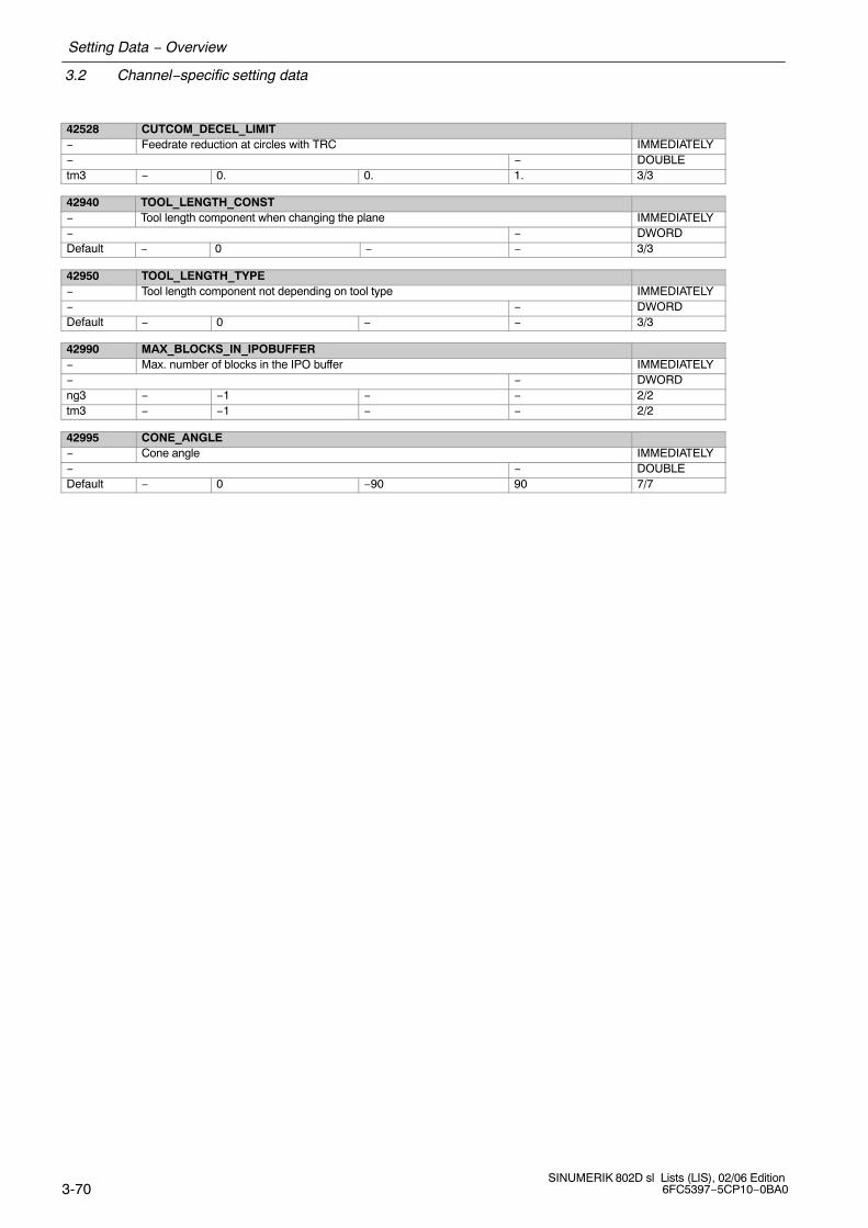
3.2 Channel−specific setting data
Setting Data − Overview
3-70SINUMERIK 802D sl Lists (LIS), 02/06 Edition
6FC5397−5CP10−0BA0
42528 CUTCOM_DECEL_LIMIT− Feedrate reduction at circles with TRC IMMEDIATELY− − DOUBLEtm3 − 0. 0. 1. 3/3
42940 TOOL_LENGTH_CONST− Tool length component when changing the plane IMMEDIATELY− − DWORDDefault − 0 − − 3/3
42950 TOOL_LENGTH_TYPE− Tool length component not depending on tool type IMMEDIATELY− − DWORDDefault − 0 − − 3/3
42990 MAX_BLOCKS_IN_IPOBUFFER− Max. number of blocks in the IPO buffer IMMEDIATELY− − DWORDng3 − −1 − − 2/2tm3 − −1 − − 2/2
42995 CONE_ANGLE− Cone angle IMMEDIATELY− − DOUBLEDefault − 0 −90 90 7/7

Setting Data − Overview
3.3 Axis−specific setting data
3-71 SINUMERIK 802D sl Lists (LIS), 02/06 Edition6FC5397−5CP10−0BA0
3.3 Axis−specific setting data
MD num-ber
SD identifier
Unit Brief description ActivationDisplay filter Attributes Data typeSystem Dimension Default value Minimum value Maximum value Protection
Note regarding the value definition: TRUE corresponds to 1
FALSE corresponds to 0
43120 DEFAULT_SCALE_FACTOR_AXIS− Default scaling factor with active G51 IMMEDIATELY− − DWORDtm1 − 1 − − 7/7tm2 − 1 − − 7/7tm3 − 1 − − 7/7
43200 SPIND_Srev/min Speed for spindle start through virtual interface IMMEDIATELY− − DOUBLEDefault − 0.0 − − 7/7
43202 SPIND_CONSTCUT_Sm/min Cutting rate for spindle start through virtual interface IMMEDIATELY− − DOUBLEDefault − 0.0 − − 7/7
43206 SPIND_SPEED_TYPE− Speed type for spindle start by VDI IMMEDIATELY− − DOUBLEDefault − 94 93 972 7/7
43210 SPIND_MIN_VELO_G25rev/min Limits the spindle speed to the specified minimum value IMMEDIATELY− − DOUBLEDefault − 0.0 − − 7/7
43220 SPIND_MAX_VELO_G26rev/min Limits the spindle speed to the specified maximum value IMMEDIATELY− − DOUBLEDefault − 1000.0 − − 7/7
43230 SPIND_MAX_VELO_LIMSrev/min Limits the spindle speed to the specified maximum value IMMEDIATELY− − DOUBLEDefault − 100.0 − − 7/7
43240 M19_SPOSdegrees Spindle position with M19 IMMEDIATELY−, − − DOUBLEDefault − 0.0 −10000000.0 10000000.0 7/7
43250 M19_SPOSMODE− Spindle position approach mode for spindle positioning with M19. IMMEDIATELY−, − − DWORDDefault − 0 0 5 7/7
43400 WORKAREA_PLUS_ENABLE− Working area limitation active in the positive direction IMMEDIATELY− CTEQ BOOLEANDefault − FALSE − − 7/7

3.3 Axis−specific setting data
Setting Data − Overview
3-72SINUMERIK 802D sl Lists (LIS), 02/06 Edition
6FC5397−5CP10−0BA0
43410 WORKAREA_MINUS_ENABLE− Working area limitation active in the negative direction IMMEDIATELY− CTEQ BOOLEANDefault − FALSE − − 7/7
43420 WORKAREA_LIMIT_PLUSmm, de-grees
Axial working area limitation active in the positive direction IMMEDIATELY
− − DOUBLEDefault − 1.0e+8 − − 7/7
43430 WORKAREA_LIMIT_MINUSmm, de-grees
Axial working area limitation active in the negative direction IMMEDIATELY
− − DOUBLEDefault − −1.0e+8 − − 7/7
43500 FIXED_STOP_SWITCH− Selection “Travel to fixed stop” IMMEDIATELY− − BYTEng2 − 0 0 1 2/2ng3 − 0 0 1 2/2tm2 − 0 0 1 2/2tm3 − 0 0 1 2/2
43510 FIXED_STOP_TORQUE% Fixed stop clamping torque IMMEDIATELY− − DOUBLEtm2 − 5.0 0.0 800.0 2/2tm3 − 5.0 0.0 800.0 2/2
43700 OSCILL_REVERSE_POS1mm, de-grees
Oscillation reversal point 1 IMMEDIATELY
− − DOUBLEng2 − 0.0 − − 7/7ng3 − 0.0 − − 7/7
43710 OSCILL_REVERSE_POS2mm, de-grees
Oscillation reversal point 2 IMMEDIATELY
− − DOUBLEng2 − 0.0 − − 7/7ng3 − 0.0 − − 7/7
43720 OSCILL_DWELL_TIME1s Hold time at oscillation reversal point 1 IMMEDIATELY− − DOUBLEng2 − 0.0 − − 7/7ng3 − 0.0 − − 7/7
43730 OSCILL_DWELL_TIME2s Hold time at oscillation reversal point 2 IMMEDIATELY− − DOUBLEng2 − 0.0 − − 7/7ng3 − 0.0 − − 7/7
43740 OSCILL_VELOmm/min,rev/min
Feedrate of reciprocating axis IMMEDIATELY
− − DOUBLEng2 − 0.0 − − 7/7ng3 − 0.0 − − 7/7

Setting Data − Overview
3.3 Axis−specific setting data
3-73 SINUMERIK 802D sl Lists (LIS), 02/06 Edition6FC5397−5CP10−0BA0
43750 OSCILL_NUM_SPARK_CYCLES− Number of spark−out strokes IMMEDIATELY− − DWORDng2 − 0 − − 7/7ng3 − 0 − − 7/7
43760 OSCILL_END_POSmm, de-grees
End position of the reciprocating axis IMMEDIATELY
− − DOUBLEng2 − 0.0 − − 7/7ng3 − 0.0 − − 7/7
43770 OSCILL_CTRL_MASK− Oscillation sequence control screenform IMMEDIATELY− − DWORDng2 − 0 − − 7/7ng3 − 0 − − 7/7
43780 OSCILL_IS_ACTIVE− Activate oscillation movement IMMEDIATELY− − BOOLEANng2 − FALSE − − 7/7ng3 − FALSE − − 7/7
43790 OSCILL_START_POSmm, de-grees
to be defined IMMEDIATELY
− − DOUBLEng2 − 0.0 − − 7/7ng3 − 0.0 − − 7/7

3.3 Axis−specific setting data
Setting Data − Overview
3-74SINUMERIK 802D sl Lists (LIS), 02/06 Edition
6FC5397−5CP10−0BA0
This sheet has been left empty for your notes.

4-75 SINUMERIK 802D sl Lists (LIS), 02/06 Edition6FC5397−5CP10−0BA0
Machine Data − Description
This Chapter describes machine data which are of general importance but for which thereare no specific chapters in this description of functions.
4.1 Display machine data
202 FIRST_LANGUAGEMD number Foreground language
Meaning: The language (1 or 2) which is to be automatically active after each system startup is set in the machinedata. Two languages are available simultaneously in SINUMERIK 802D. Languages other than those included inthe control ex works can be loaded. It is possible to temporarily switch to a second language using a softkey in the Diagnosis area. After powerON the predefined language set in MD is again active.
References ”Operation and Programming”
203 DISPLAY_RESOLUTIONMD number Display resolution
Meaning: This machine data defines the number of places after the decimal point in the position display for linearaxes in metric systems as well as in general for rotary axes.Spindle positions are treated as rotary axis positions.The position is displayed with 10 symbols max. including the plus/minus sign and the decimal point. A plussign is not displayed.All 3 positions after the decimal point are displayed per default.� MD value=3: Display resolution = 10−3 [mm] or [degrees].
Related to .... MD 10200: INT_INCR_PER_MM or MD 10210: INT_INCR_PER_DEG
204 DISPLAY_RESOLUTION_INCHMD number Display resolution for the INCH dimension system
Meaning: This machine data specifies the number of places after the decimal point for linear axes for Inch dimensionsystems.The position is displayed with max. 10 characters including the plus/minus sign and the decimal point. Aplus sign is not displayed.All 4 positions after the decimal point are displayed per default.� MD value=4: Display resolution = 10 −4 [inch]The display is retained according to MD 203 for rotary axes and spindle positions
Related to .... MD 10200: INT_INCR_PER_MM, MD 203: DISPLAY_RESOLUTION
205 DISPLAY_RESOLUTION_SPINDLEMD number Display resolution for spindle valuesMeaning: This machine data specifies the number of places after the decimal point of the spindle speed display.
The values are displayed with 10 symbols max. including the plus/minus sign and the decimal point. Aplus sign is not displayed.1 position after the decimal point is displayed per default.� MD value=1: Display resolution = 10−1
4

4.1 Display machine data
Machine Data − Description
4-76SINUMERIK 802D sl Lists (LIS), 02/06 Edition
6FC5397−5CP10−0BA0
289 CTM_SIMULATION_TIME_NEW_POSMD number Simulation updating rate of actual valueMeaning: This MD is set to specify the time intervals at which the simulation graphic must be updated in accordance
with the current machining process on the machine tool.Value = 0 means no update.
Note for the reader: SINUMERIK 802D sl Description of Functions: K1
290 CTM_POS_COORDINATE_SYSTEMMD number Simulation of actual-value refresh rateMeaning: The position of the coordinate system can be altered as follows:
0
+X
+Z
+X
+Z
2
4
6
1
3
5
7
+X
+Z
+X
+Z
+Z
+X +X
+Z
+X
+Z
+X
+ZNote for the reader: SINUMERIK 802D sl Description of Functions: K1
291 CTM_CROSS_AX_DIAMETER_ONMD number Diameter display for active transverse axesMeaning: 0: Inputs for absolute values as radius value.
Zero offsets always as radius,tool lengths always as radius,tool wear always as radius
1: Position display as diameter,distance to go as diameterabsolute distances as diameter
Note for the reader: SINUMERIK 802D sl Description of Functions: K1
292 CTM_G91_DIAMETER_ONMD number Incremental infeedMeaning: 0: Input in radius
1: Input in diameterNote for the reader: SINUMERIK 802D sl Description of Functions: K1
361 MEAS_TOOL_CHANGEMD number Input enable for T/D no. for tool measuringMeaning: 0: T/D number input blocked
1: T/D number input enabledNote for the reader: SINUMERIK 802D sl Description of Functions: M5

Machine Data − Description
4.1 Display machine data
4-77 SINUMERIK 802D sl Lists (LIS), 02/06 Edition6FC5397−5CP10−0BA0
373 MEAS_SAVE_POS_LENGTH2MD number Enable tool measuring SK ”Save Pos” for all values.Meaning: Controls ”Save/Pos” softkey for ”Manual tool measuring” function:
0: The SK ”Save Pos” is only active when measuring length 11: SK ”Save Pos” is generally active
Note for the reader: SINUMERIK 802D sl Description of Functions: M5

4.2 General machine data
Machine Data − Description
4-78SINUMERIK 802D sl Lists (LIS), 02/06 Edition
6FC5397−5CP10−0BA0
Machine Data − Description
4.2 General machine data
10000 AXCONF_MACHAX_NAME_TAB[0]...[4]MD number Machine axis name
Meaning: The name of the machine axis is entered in this MD
� The preferred axis label (name) should be used comprising a valid address letter (A, B, C, Q, U, V, W, X, Y, Z), followed by an optional, numerical expansion (1−99).
� The selected machine axis label (name) must differ from the label (name) of geometry axes (X, Y, Z) andadditional channel axes (MD 20080: AXCONF_CHANAX_NAME_TAB if a transformation is planned(e.g.: TRANSMITT). Comment: Transformation for SINUMERIK 802D, SW release P1, transformations are not available.
� A “free” entered machine axis label (axis name) may not be a name, address, keyword or predefinedlabel or name that is already being used in the control or is reserved for other functions (e.g.: SPOS,DIAMON, ...). Note: Not all the SINUMERIK control system functions are documented for 802D. Use of a free axisidentifier is therefore conditional.
Special cases, errors, ... ... We recommend the following for machine axis identifiers:X1, Y1, Z1, U1, V1, W1, Q1 for linear axes,A1, B1, C1 for rotary axes
Related to .... MD 20060: AXCONF_GEOAX_NAME_TAB (geometry axis identifier)MD 20080 :AXCONF_CHANAX_NAME_TAB (channel axis identifier)
10074 PLC_IPO_TIME_RATIOMD number PLC task factor for main run (IPO)
Meaning: Division ratio between IPO and PLC tasks. A value of 2 means, for example, that the PLC task is processed in every second IPO cycle only. The PLCcycle time therefore equals 2 IPO times. More runtime is therefore available for the other tasks.The PLC runtime must not exceed this PLC cycle time, or a PLC STOP alarm will be triggered.
Application example(s)
10200 INT_INCR_PER_MMMD number Calculation resolution for linear positionsMeaning: The number of internal increments per millimeter is defined in this MD. The precision of the linear position
input is limited to the calculation resolution by rounding-off the product of the programmed value and the cal-culation resolution to an integer value. To make the rounding clear, powers of 10 should be used for the calcu-lation resolution.
Application example(s) The calculation resolution can be increased to �1000 incr./mm for linear axes operating to high accuracyrequirements.
Note for the reader: SINUMERIK 802D sl Description of Functions: G2
10210 INT_INCR_PER_DEGMD number Computational resolution for angular positionsMeaning: The number of internal increments per degree is defined in this MD. The precision of the angular position
input is limited to the calculation resolution by rounding-off the product of the programmed value and the cal-culation resolution to an integer value. To make the rounding clear, powers of 10 should be used for the calcu-lation resolution.
Application example(s) The calculation resolution can be changed to �1000 incr./degrees for a high-resolution rotary axis.Note for the reader: SINUMERIK 802D sl Description of Functions: G2

Machine Data − Description
4.2 General machine data
4-79 SINUMERIK 802D sl Lists (LIS), 02/06 Edition6FC5397−5CP10−0BA0
10240 SCALING_SYSTEM_IS_METRICMD number Basic system metricMeaning: The MD defines the basic system used by the control to scale length-dependent physical
quantities during data input/output.All related data are stored internally in the basic units 1 mm, 1 degree and 1 sec.When accessing a part program via the operator panel or from an external device, scaling is in thefollowing units:SCALING_SYSTEM_IS_METRIC = 1: normalized to:
mm, mm/min, m/s2, m/s3mm/rev SCALING_SYSTEM_IS_METRIC = 0: normalized to:
inch, inch/min, inch/s2inch/s3, inch/revThe selection of the basic system also specifies the interpretation of the programmed F value forlinear axes:
metric inchG94 mm/min inch/minG95 mm/rev inch/revA power-up is necessary after changing this machine data, as associated machine data that havephysical units will otherwise be normalized incorrectly.Perform the following steps:� MD change by manual input
� First perform start-up and then enter the physical units in the related machinedata.
� MD change via machine data file� First perform start-up and then reload the machine data file
so that the new physical units are activated.
If the machine data are altered, alarm 4070 “Scaling machine data altered” is output.Application example(s) Installation in the metric system and then conversion to inch system.Note for the reader: SINUMERIK 802D sl Description of Functions: G2
11100 AUXFU_MAXNUM_GROUP_ASSIGNMD number Number of auxiliary functions distributed among the AUXFU groupsMeaning: The number of the auxiliary functions that have been distributed to the groups must be entered in the MD.
This number only includes the customer-specific auxiliary functions, not the predefined auxiliary functions.Application example(s)Related to .... MD 22010: AUXFU_ASSIGN_TYPE [n] (auxiliary function type)Note for the reader: SINUMERIK 802D sl Description of Functions: H2
11210 UPLOAD_MD_CHANGES_ONLYMD number MD backup of changed MD only
Meaning: Selection of differential MD upload:Bit0(LSB) Effectiveness of the differential upload for TEA files (machine data files)
0: All data are output 1: only the values changed as compared to the compiled MD are output
Bit1 Effectiveness of the differential upload for INI files 0: All data are output 1: only the values changed as compared to the compiled MD are output
Bit2 change of a field element0: complete arrays are output1: only changed field elements of an array are output
Bit3 R parameter (for INI files only)0: All R parameters are output1: only R parameters unequal to ’0’ are output
Bit4 frames (for INI files only)0: All frames are output 1: only frames are output which are not zero frames.
Bit5 tool data (cutting edge parameter) (for INI files only)0: All tool data are output 1: only tool data unequal to ’0’ are output.

4.2 General machine data
Machine Data − Description
4-80SINUMERIK 802D sl Lists (LIS), 02/06 Edition
6FC5397−5CP10−0BA0
11240 PROFIBUS_SDB_NUMBERMD number SDB1000 number
Meaning: BUS_SDB_NUMBER [0] = 0Digital inputs and outputs via I/O modules (PP modules)The assignment is provided via DIL switches. Max. 3 modules with the addresses 9, 8 and 7 are possible.
PROFIBUS_SDB_NUMBER [2] = XNumber of the system module you are using for configuring the hardware I/Os.SINUMERIK 802D sl offers the following options to choose from:
0: 2 SINAMICS drives with SLM1: 3 SINAMICS drives with SLM2: 4 SINAMICS drives with SLM3: 5 SINAMICS drives with SLM
4: 3 SINAMICS drives with ALM5: 4 SINAMICS drives with ALM5: 4 SINAMICS drives with ALM6: 5 SINAMICS drives with ALM
Note: With the SDB reloaded from the toolbox, PROFIBUS_SDB_NUMBER[2] = 0 must be set. This activates themodule.The machine data PROFIBUS_SDB_NUMBER[1] and PROFIBUS_SDB_NUMBER[3] are reserved internallyfor Siemens.
Note for the reader: SINUMERIK 802D sl Description of Functions: G2
11310 MN_HANDWH_REVERSEMD number Threshold for change in handwheel directionMeaning: 0: No immediate movement in the opposite direction
> 0: Immediate movement in the opposite direction if the handwheel is turned in the opposite direction by atleast the number of pulses indicated
Note for the reader: SINUMERIK 802D sl Description of Functions: H1
11320 HANDWH_IMP_PER_LATCH[0]...[2]MD number Handwheel pulses per detent position [handwheel index]:Meaning: This adapts the connected handwheels to the control system.
The number of pulses generated by the handwheel for each handwheel detent position is entered. Thehandwheel pulse weighting may be defined for each connected handwheel (1 to 2) separately.When adapted to the control, each handwheel detent position has the same effect as one press of the tra-verse key in incremental jogging mode.If a negative value is entered, the handwheel is active in the reverse direction.
Related to .... MD: JOG_INCR_WEIGHT (weighting of an increment of a machine axis for INC/manual).Note for the reader: SINUMERIK 802D sl Description of Functions: H1
11346 HANDWH_TRUE_DISTANCEMD number Handwheel path or velocity valuesMeaning: 0: The settings from the handwheel are velocity settings. When the handwheel is stationary, braking is
realized along the shortest path.1: The settings from the handwheel are distance settings. No pulses are lost. Limiting the velocity to the
maximum permissible value can cause the axes to overtravel.2: Effect as for value=0, however, with a longer braking travel when the handwheel is stationary.3: Effect as for value=1, however, with a longer braking travel when the handwheel is stationary.
Related to ....Note for the reader: SINUMERIK 802D sl Description of Functions: H1

Machine Data − Description
4.2 General machine data
4-81 SINUMERIK 802D sl Lists (LIS), 02/06 Edition6FC5397−5CP10−0BA0
13060 DRIVE_TELEGRAM_TYPE[n]MD number Default message frame type for drives connected to PROFIBUS DPMeaning: The message frame type:
102: must be specified for each drive. Standard message frame for SINAMICS actual-value assignment102: must be specified for each drive. Standard message frame for SINAMICS actual value assignment103: SINAMICS− Spindle with second direct measuring systemIndex [n] of the machine data has the following code: [drive index]: Index [n] of the machine data has the following code: [drive index]:
n=0: Drive number 1 n=1: Drive number 2, etc.
Note for the reader: SINUMERIK 802D sl Description of Functions: G2
13200 MEAS_PROBE_LOW_ACTIVE[0]MD number Switching characteristics of probeMeaning: 0: non-deflected status 0 V deflected status 24 V
1: non-deflected status 24 V deflected status 0 VNote for the reader: SINUMERIK 802D sl Description of Functions: M5
14510 USER_DATA_INT[0]...[31]MD number User data (INT)
Meaning: User machine data, evaluation in PLC (displayed as whole number, decimal)
14512 USER_DATA_HEX[0]...[31]MD number User data (HEX)
Meaning: User machine data, evaluation in PLC (display in HEX format) 1)
14514 USER_DATA_FLOAT[0]...[7]MD number User data (FLOAT)
Meaning: User machine data, evaluation in PLC (floating point format, restricted to 32Bit IEEE format in PLC)
14516 USER_DATA_PLC_ALARM[0]...[31]MD number User data (HEX)
Meaning: User data, evaluation in PLC (display in HEX format) 1)
18080 ** MM_TOOL_MANAGEMENT_MASKMD number Memory reservation for the tool monitoring
Meaning: Value = 0: no memory is reserved, tool monitoring not possibleValue = 0x2: Monitoring data/memory is made available
(only possible if “Tool monitoring” option is present)
Related to .... MD 20310: TOOL_MANAGEMENT_MASKNote for the reader: SINUMERIK 802D sl Description of Functions: W1
** This machine data is not available with 802D sl value.

4.3 Channel-specific machine data
Machine Data − Description
4-82SINUMERIK 802D sl Lists (LIS), 02/06 Edition
6FC5397−5CP10−0BA0
Machine Data − Description
4.3 Channel-specific machine data
20050 AXCONF_GEOAX_ASSIGN_TAB[0]...[2]MD number Assignment between geometry axis and channel axis
Meaning: This MD assigns a geometry axis to a channel axis.The assignment must be made for all 3 geometry axes (X,Y,Z). If a geometry axis is not assigned, the value 0should be entered. The geometry axis is therefore not available and cannot be programmed, e.g. if the se-cond geometry axis is not required for the ”turning” technology Y −> entry: value 0 (see default setting forturning).
Special cases, errors, ... ... It is advisable to assign the first channel axes to the geometry axes.
20070 AXCONF_MACHAX_USED[0]...[4]MD number Machine axis number valid in channel
Meaning: This MD assigns a machine axis to a channel axis. SINUMERIK 802D has 5 channel axes. Channel axis identifiers for the axes activated in the channel must be specified in MD 20080: AXCONF_CHA-NAX_NAME_TAB. The axes can be programmed.
A machine axis that has not been assigned to a channel axis is not active i.e. no axis control, no display onthe screen.
Special cases, errors, ... ... A channel axis and therefore indirectly a machine axis must be assigned to each geometry axis to be pro-grammed. The remaining axes (besides the geometry axes) in the channel are additional axes − also pro-grammable.
Application example(s) Example of assigning the machine axis (MA) to the channel axes:AXCONF_MACHAX_USED [0] = 3 ;3rd MA is 1st axis in the channelAXCONF_MACHAX_USED [1] = 1 ;1st MA is 2nd axis in the channel AXCONF_MACHAX_USED [2] = 5 ;5th MA is 3rd axis in the channel AXCONF_MACHAX_USED [3] = 0 ; no assignment
Note: Leave no spaces!, Example of programming error:AXCONF_MACHAX_USED [0] = 1 ;1st MA is 1st axis in the channelAXCONF_MACHAX_USED [1] = 2 ;2nd MA is 2nd axis in the channelAXCONF_MACHAX_USED [2] = 0 ;space in list ... AXCONF_MACHAX_USED [3] = 3 ;... of the channel axes
Related to .... MD 20080: AXCONF_CHANAX_NAME_TAB[0]...[4] (channel axis identifier)
20080 AXCONF_CHANAX_NAME_TAB[0]...[4]MD number Channel axis name
Meaning: In this MD you can set the name of the channel axis. The channel axis is displayed with this identifier in the WCS. This identifier is also written in the program.Generally, the first two or three channel axes are used as geometry axes (see also MD 20050: AX-CONF_GEOAX_ASSIGN_TAB). The remaining channel axes are defined as special axes. SINUMERIK 802D has 5 channel axes.
Special cases, errors, ... ... We recommend the following for the channel axis identifiers:X, Y, Z, U, V, W, Q for linear axes,A, B, C for rotary axesIf you decide to use names other than those recommended, follow the rules for creating axis identifiers (seeMD 10000: AXCONF_MACHAX_NAME_TAB).

Machine Data − Description
4.3 Channel-specific machine data
4-83 SINUMERIK 802D sl Lists (LIS), 02/06 Edition6FC5397−5CP10−0BA0
20090 SPIND_DEF_MASTER_SPINDMD numberMeaning: Definition of the master spindle default setting (in channel).
The spindle number is entered.A series of functions are linked to the master spindle which are not possible for a different spindle.Note:The SETMS(n) language command can be used to declare the spindle number n as master spindle. The spindle defined as master spindle in this MD is declared as master spindle again with SETMS.At the program end or program termination, the spindle defined in this MD is also declared as master spindle.
Further referencesNote for the reader: SINUMERIK 802D sl Description of Functions: S1
20140 TRAFO_RESET_VALUEMD number Active transformation following RESETMeaning: Definition of the transformation data set selected during booting and for a
reset or an end of the part program.(In conjunction with machine data $MC_RESET_MODE_MASK and for a part program start in conjunctionwith machine data $MC_START_MODE_MASK)
Note for the reader: SINUMERIK 802D sl Description of Functions: M1
20310 ** TOOL_MANAGEMENT_MASKMD number Activation of the tool monitoring
Meaning: Value = 0: no tool monitoring Value = 0x2: Tool monitoring activated (only possible if ”Tool monitoring” option is present)
Related to .... MD 18080: MM_TOOL_MANAGEMENT_MASKNote for the reader: SINUMERIK 802D sl Description of Functions: W1
** This machine data is not available with 802D sl value.
20360 TOOL_PARAMETER_DEF_MASKMD number Definition of tool parameters
Meaning: Bit 0 = 0: For turning tools the wear parameter of the transverse axis X is applied as a radius value.
Bit 0 = 1: For turning tools the wear parameter of the transverse axis X is applied as a diameter value.
Special cases, errors, ... ...Note for the reader: SINUMERIK 802D sl Description of Functions: W1
20700 REFP_NC_START_LOCKMD number NC start disable without reference pointMeaning: 0: The ”NC start” interface signal (V3200 0007.1) for starting part programs or part program blocks (MDA) is
also possible if none or not all channel axes are referenced. To ensure that the axes move to the correctposition after NC Start, the workpiece coordinate system (WCS) must be set to a correct value by othermethods (scratching method).
1: The NC only starts if all of the axes have been referenced.Note for the reader: SINUMERIK 802D sl Description of Functions: R1

4.3 Channel-specific machine data
Machine Data − Description
4-84SINUMERIK 802D sl Lists (LIS), 02/06 Edition
6FC5397−5CP10−0BA0
21000 CIRCLE_ERROR_CONSTMD number Circle end point monitoring constant
Meaning: This machine data identifies the permissible absolute circle difference.In circle programming, the radii from the programmed center point to the starting point and to the end pointare usually not equal (the circle is ”overdefined”). The maximum permissible difference between these tworadii which is accepted without an alarm being triggered is defined by the larger value in the following data:− MD: CIRCLE_ERROR_CONST− Start radius multiplied by 0.001I.e. for small circles the tolerance is a fixed value (MD: CIRCLE_ERROR_CONST) and for large circles itis proportional to the start radius.
Application example MD 21000: CIRCLE_ERROR_CONST = 0.01 mmWith these MD and a radius � 10mm, the constant has an effect, with > 10mm, the proportional factor hasan effect.
Note for the reader: SINUMERIK 802D sl Description of Functions: K1
21020 WORKAREA_WITH_TOOL_RADIUSMD number Allowance for tool radius with working area limitingMeaning: 0: The tool radius is not taken into account.
1: The tool radius is taken into account with respect to the working area limit.Note for the reader: SINUMERIK 802D sl Description of Functions: A3
22000 AUXFU_ASSIGN_GROUP[n]MD number Auxiliary function group [aux. func. no. in channel]: 0 ... 63Meaning: see MD 22010: AUXFU_ASSIGN_TYPE [n] (auxiliary function type)Application example(s)Note for the reader: SINUMERIK 802D sl Description of Functions: H2
22010 AUXFU_ASSIGN_TYPE[n]MD number Auxiliary function type [aux. func. no. in channel]: 0 ... 63Meaning: This MD (auxiliary function type) and MD 22020: AUXFU_ASSIGN_EXTENSION[n] (auxi-
liary function extension) and MD 22030: AUXFU_ASSIGN_VALUE[n] (auxiliary functionvalue) and MD 22000: AUXFU_ASSIGN_GROUP[n] (auxiliary function group) are used toallocate an auxiliary function type (M, H, T, D, S), the related extension and the auxiliaryfunction value to an auxiliary function group.Example: M 0 = 99 => Group 5 (corresponds to M99)
Auxiliary function typeAuxiliary function extensionAuxiliary function valueAuxiliary function group
⇒ MD: AUXFU_ASSIGN_TYPE[0] = MMD: AUXFU_ASSIGN_EXTENSION[0] = 0 ; other values only for type HMD: AUXFU_ASSIGN_VALUE[0] = 99MD: AUXFU_ASSIGN_GROUP[0] = 5 ; (Group 5)
M00, M01, M02, (M17 and M30) are assigned to Group 1 by default. M3, M4, M5 are assi-gned to Group 2 by default.
The machine data index [n] indicates the auxiliary function number in the channel: 0−63All auxiliary functions that are assigned to auxiliary function groups must be numbered inascending order.[0]�1st auxiliary function[1]�2. ,, ...The machine data for the allocation of an auxiliary function to an auxiliary function groupmust be provided with the same index [n].
Special cases, errors, ... ... If the auxiliary function value of an auxiliary function is less than 0, then all auxiliary functions of this type andextension are assigned to a group.
Related to .... MD 11100: AUXFU_MAXNUM_GROUP_ASSIGNNote for the reader: SINUMERIK 802D sl Description of Functions: H2

Machine Data − Description
4.3 Channel-specific machine data
4-85 SINUMERIK 802D sl Lists (LIS), 02/06 Edition6FC5397−5CP10−0BA0
22020 AUXFU_ASSIGN_EXTENSION[n]MD number Auxiliary function extension [aux. func. no. in channel]: 0 ... 63Meaning: see MD 22010: AUXFU_ASSIGN_TYPE [n] (auxiliary function type)Application example(s)
22030 AUXFU_ASSIGN_VALUE[n]MD number Auxiliary function value [aux. func. no. in channel]: 0 ... 63Meaning: If the value in this MD is smaller than 0 all auxiliary functions of this type and this
address extension are assigned to this group.See MD 22010: AUXFU_ASSIGN_TYPE [n] (auxiliary function type)
Note for the reader: SINUMERIK 802D sl Description of Functions: H2
22534 TRAFO_CHANGE_M_CODEMD number M code for transformation changeoverMeaning: Number of M code that is output at the VDI interface in the case of a transformation changeover on the geo-
metry axes. No M code is output if this MD is set to one of the values 0 to 6, 17 or 30. It is not monitored whether an M code created in this way will conflict with other functions.
Note for the reader: SINUMERIK 802D sl Description of Functions: M1
22550 TOOL_CHANGE_MODEMD number New tool offset for M functionMeaning: The T function is used to select a tool in a program. The setting in this machine data determines whether the
new tool is loaded immediately on execution of the T function:
1: The new tool is prepared for changing with the T function. This setting is used mainly on milling machi-nes with a tool magazine, in order to bring the new tool into the tool change position without interrupting themachining process. The old tool is removed from the spindle with an M function and the new tool is loadedinto the spindle. According to DIN 66025, this tool change is programmed using the M function M6.
Related to ....Note for the reader: SINUMERIK 802D sl Description of Functions: W1
24100 TRAFO_TYPE_1MD number Type of 1st transformationMeaning:
0 no transformation256 TRANSMIT transformation512 TRACYL transformation513 TRACYL transformation with X-Y-Z-C kinematics
further transformations are not available with SINUMERIK 802D.
Transformation type of 1st transformation:
MD irrelevant for ... ... No transformationsRelated to .... TRAFO_TYPE_2Note for the reader: SINUMERIK 802D sl Description of Functions: M1
24110 TRAFO_AXES_IN_1[i]MD number Axis assignment for transformation 1 [axis index]: 0 ... 4Meaning: Axis assignment at input of 1st transformation
Example for Transmit:Index i assumes the values 0,1, 2 with TRANSMIT.$MC_TRAFO_AXES_IN_1[0]= channel axis number of axis perpendicular to rotary axis$MC_TRAFO_AXES_IN_1[1]= channel axis number of rotary axis$MC_TRAFO_AXES_IN_1[2]= channel axis number of axis parallel to rotary axisExample for TRACYL: see TRACYL section
MD irrelevant for ... ... No transformationRelated to .... TRAFO_AXES_IN_2Note for the reader: SINUMERIK 802D sl Description of Functions: M1

4.3 Channel-specific machine data
Machine Data − Description
4-86SINUMERIK 802D sl Lists (LIS), 02/06 Edition
6FC5397−5CP10−0BA0
24120 TRAFO_GEOAX_ASSIGN_TAB_1[i]MD number Assignment of geometry axes to channel axes with transformation 1
[geometry axis number]: 0 ... 2Meaning: This MD specifies the channel axes on which the axes of the Cartesian coordinate system
are mapped when transformation 1 is active.Index i assumes the values 0, 1, 2 with TRANSMIT. It refers to the first, second and third geometry axis.
MD irrelevant for ... ... No transformationApplication example(s) $MC_TRAFO_GEOAX_ASSIGN_TAB_1[0]= 2 ; 2nd channel axisRelated to .... $MC_AXCONF_GEOAX_ASSIGN_TAB, if no transformation is active.Note for the reader: SINUMERIK 802D sl Description of Functions: M1
24200 TRAFO_TYPE_2MD number Type of transformationMeaning: Same as TRAFO_TYPE_1, but for transformation 2Note for the reader: SINUMERIK 802D sl Description of Functions: M1
24210 TRAFO_AXES_IN_2[i]MD number Axis assignment for transformation 2/3/4/5/6/7/8 [axis index]: 0 ... 4Meaning: Axis assignment at input of 2nd transformation.
Same meaning as for TRAFO_AXES_IN_1.Note for the reader: SINUMERIK 802D sl Description of Functions: M1
24220 TRAFO_GEOAX_ASSIGN_TAB_2[i]MD number Assignment of geometry axes to channel axes with transformation 2
[geometry axis number]: 0 ... 2Meaning: The channel axes on which the axes of the Cartesian coordinate system are mapped
when transformation 2 is active are set in this MD. The meaning otherwise corresponds to TRAFO_GEOAX_ASSIGN_TAB_1.
Note for the reader: SINUMERIK 802D sl Description of Functions: M1
24800 TRACYL_ROT_AX_OFFSET_1MD number Offset of rotary axis for the TRACYL transformationMeaning: Specifies the offset of the rotary axis in degrees in relation to the zero position while TRACYL is active for the
first declared TRACYL transformation for each channel.MD irrelevant for ... ... No TRACYL activeApplication example(s) $MC_TRACYL_ROT_AX_OFFSET_1=15.0Note for the reader: SINUMERIK 802D sl Description of Functions: M1
24810 TRACYL_ROT_SIGN_IS_PLUS_1MD number Sign of rotary axis for the TRACYL transformationMeaning: Specifies the sign which is applied to the rotary axis during the TRACYL transformation for the TRACYL
transformation.MD irrelevant for ... ... No TRACYL transformationApplication example(s) $MC_TRACYL_ROT_SIGN_IS_PLUS_1 = 1Note for the reader: SINUMERIK 802D sl Description of Functions: M1
24820 TRACYL_BASE_TOOL_1[i]MD number Vector of base tool for TRACYL transformation, [Geo-Axis-Index]: 0 ... 2Meaning: MD specifies the distance of the tool zero point referred to the appropriate geometry axes valid with TRACYL
active and without tool length offset selected for the TRACYL transformation. Programmed length compensations are added to the base tool. Index i assumes values 0, 1, 2 for the 1st to 3rd geometry axes.
MD irrelevant for ... ... No TRACYL transformationApplication example(s) $MC_TRACYL_BASE_TOOL_1[0]=txNote for the reader: SINUMERIK 802D sl Description of Functions: M1

Machine Data − Description
4.3 Channel-specific machine data
4-87 SINUMERIK 802D sl Lists (LIS), 02/06 Edition6FC5397−5CP10−0BA0
24900 TRANSMIT_ROT_AX_OFFSET_1MD number Position offset of rotary axisMeaning: Specifies the offset of the rotary axis in degrees in relation to the zero position − while TRANSMIT is active −
for the TRANSMIT transformation.MD irrelevant for ... ... No TRANSMIT activeApplication example(s) $MC_TRANSMIT_ROT_AX_OFFSET_1=15.0Note for the reader: SINUMERIK 802D sl Description of Functions: M1
24910 TRANSMIT_ROT_SIGN_IS_PLUS_1MD number Sign of rotary axisMeaning: Specifies the sign which is applied to the rotary axis during the TRANSMIT transformation for the TRANSMIT
transformation.MD irrelevant for ... ... No TRANSMIT transformationApplication example(s) $MC_TRANSMIT_ROT_SIGN_IS_PLUS_1= 1Note for the reader: SINUMERIK 802D sl Description of Functions: M1
24911 TRANSMIT_POLE_SIDE_FIX_1MD number Restriction of working range in front of/behind poleMeaning: Restriction of working range in front of/behind pole or no restrictions, i.e. traversal through pole.
The setpoints have the following meanings:0: No restrictions of working range. Traversal through pole.
1: Working range of linear axis for positions >=0, (if tool length compensation parallel to linear axis equals 0)
2: Working range of linear axis for positions <=0, (if tool length compensation parallel to the linear axis equals 0)
Note for the reader: SINUMERIK 802D sl Description of Functions: M1
24920 TRANSMIT_BASE_TOOL_1[i]MD number Vector of base tool on activation of transformation, [Geo-Axis-Index]]: 0 ... 2Meaning: MD specifies the distance of the tool zero point referred to the appropriate geometry axes valid with TRANS-
MIT active and without tool length offset selected for the TRANSMIT transformation. Programmed length compensations are added to the base tool. Index i assumes values 0, 1, 2 for the 1st to 3rd geometry axes.
MD irrelevant for ... ... No TRANSMIT transformationApplication example(s) $MC_TRANSMIT_BASE_TOOL_1[0]=20.0Note for the reader: SINUMERIK 802D sl Description of Functions: M1
27800 TECHNOLOGY_MODEMD number Technology in channel
Meaning: Selection of the technology for display and operating purposes (HMI)0: Milling1: TurningThis makes technology-dependent displays and softkeys available in the HMI.
Special cases, errors, ... ...

4.3 Channel-specific machine data
Machine Data − Description
4-88SINUMERIK 802D sl Lists (LIS), 02/06 Edition
6FC5397−5CP10−0BA0
27860 PROCESSTIMER_MODEMD number Activating the program runtime measurement
Meaning: The channel-specific timers can be activated/deactivated through this machine data.
Meaning:Bit 0 = 0 No measurement of the total runtime for all part programsBit 0 = 1 The measurement of the total runtime for all part programs
is active ( $AC_OPERATING_TIME )Bit 1 = 0 No measurement of the current program runtimeBit 1 = 1 The measurement of the current program runtime is active
( $AC_CYCLE_TIME )Bit 2 = 0 No measurement of the tool cutting timeBit 2 = 1 The measurement of the tool cutting time is active
( $AC_CUTTING_TIME )Bit 3 Reserved
Further bits only for Bit 0, 1, 2 = 1:Bit 4 = 0 No measurement with active dry run feedrateBit 4 = 1 Measurement also with active dry run feedBit 5 = 0 No measurement in program testBit 5 = 1 Measurement also in program testBit 6, 7 Reserved
Application example
Special cases, errors, ......
It is recommended that timers that are never used are deactivated. This helps the free-up computationaltime other user applications.
Note for the reader: SINUMERIK 802D sl Description of Functions: K1

Machine Data − Description
4.3 Channel-specific machine data
4-89 SINUMERIK 802D sl Lists (LIS), 02/06 Edition6FC5397−5CP10−0BA0
27880 PART_COUNTERMD number Activation of the workpiece counters
Meaning: The workpiece counters can be set with this machine data.Meaning of the individual Bits:Bit 0 − 3: Activation $AC_REQUIRED_PARTS−−−−−−−−−−−−−−−−−−−−−−−−−−−−−−−−−−−−−−−−−−−−−−Bit 0 = 1: Counter $AC_REQUIRED_PARTS is activeFurther meaning Bit 1−3 only when bit 0 =1:Bit 1 = 0: Alarm IS output when $AC_ACTUAL_PARTS
matches $AC_REQUIRED_PARTSBit 1 = 1: Alarm IS output when $AC_SPECIAL_PARTS
matches $AC_REQUIRED_PARTS Bit 2, 3 Reserved
Bit 4 − 7: Activation $AC_TOTAL_PARTS−−−−−−−−−−−−−−−−−−−−−−−−−−−−−−−−−−−−−−−−−−−BBit 4 = 1: Counter $AC_TOTAL_PARTS is activeFurther meaning Bit 5−7 only when Bit 4 =1:Bit 5 = 0: Counter $AC_TOTAL_PARTS is incremented by 1 on output of M2/M30. Bit 5 = 1: Counter $AC_TOTAL_PARTS is incremented by 1 on the M command from
MD 27882: PART_COUNTER_MCODE[0] Bit 6 = 0: Counter $AC_TOTAL_PARTS also active in program test/block searchBit 6 = 1: no processing $AC_TOTAL_PARTS in program test/block searchBit 7 Reserved
Bit 8 − 11: Activation $AC_ACTUAL_PARTS−−−−−−−−−−−−−−−−−−−−−−−−−−−−−−−−−−−−−−−−−−−−Bit 8 = 1: Counter $AC_ACTUAL_PARTS is activeFurther meaning Bit 9−11 only when Bit 8 =1:Bit 9 = 0: Counter $AC_ACTUAL_PARTS is incremented by 1 on output of M2/M30. Bit 9 = 1: Counter $AC_ACTUAL_PARTS is incremented by 1 on the M command from
MD 27882: PART_COUNTER_MCODE[1]Bit 10 = 0: Counter $AC_ACTUAL_PARTS also active in program test/block searchBit 10 = 1: no processing $AC_ACTUAL_PARTS in program test/block searchBit 11 Reserved
Bit 12 − 15: Activation $AC_SPECIAL_PARTS−−−−−−−−−−−−−−−−−−−−−−−−−−−−−−−−−−−−−−−−−−−−−Bit 12 = 1: Counter $AC_SPECIAL_PARTS is activeFurther meaning Bit 13−15 only when Bit 12 =1:Bit 13 = 0: Counter $AC_SPECIAL_PARTS is incremented by 1 on output of M2/M30Bit 13 = 1: Counter $AC_SPECIAL_PARTS is incremented by 1 on output of the M command from
MD 27882: PART_COUNTER_MCODE[2]Bit 14, 15 Reserved
Application example
Related to .... MD 27882: PART_COUNTER_MCODEIS ”Required number of workpieces reached” (V3300 40001.1)
Note for the reader: SINUMERIK 802D sl Description of Functions: K1
27882 PART_COUNTER_MCODE[n] n = 0 ... 2 , index for counter assignmentMD number Workpiece counting via M command
Meaning: On activation of workpiece counting through MD 27880: PART_COUNTER the counting pulse can be trig-gered by a special M command.Only in this case are the values defined here observed.Meaning:The workpiece counters are incremented by 1 at the IS signal output of the describedM command. The following applies:
$PART_COUNTER_MCODE[0] for $AC_TOTAL_PARTS$PART_COUNTER_MCODE[1] for $AC_ACTUAL_PARTS$PART_COUNTER_MCODE[2] for $AC_SPECIAL_PARTS
Application example
Related to .... MD 27880: PART_COUNTERNote for the reader: SINUMERIK 802D sl Description of Functions: K1

4.4 Axis-specific machine data
Machine Data − Description
4-90SINUMERIK 802D sl Lists (LIS), 02/06 Edition
6FC5397−5CP10−0BA0
Machine Data − Description
4.4 Axis-specific machine data
30110 CTRLOUT_MODULE_NR[n]MD number Setpoint: Drive number/module numberMeaning: For a standard axis, the drive number must be entered.
Index [n] of the machine data is coded as follows: [setpoint branch]: 0Note for the reader: SINUMERIK 802D sl Description of Functions: G2
30120 CTRLOUT_NR[n]MD number Setpoint: Output to module:Meaning: The number of the output on a module via which the setpoint output is addressed is entered here.
Index[n] of the machine data is coded as follows: [setpoint branch]: 0Note for the reader: SINUMERIK 802D sl Description of Functions: G2
30130 CTRLOUT_TYPE[n]MD number Output type of setpointMeaning: The speed setpoint output type is entered in the MD:
0: Simulation (no HW required)1: Setpoint output activeThe index [n] of the machine data has the following code: [setpoint branch]: 0
Application example(s) Simulation: Machine functions can be simulated even if there is no drive system.Note for the reader: SINUMERIK 802D sl Description of Functions: G2
30134 IS_UNIPOLAR_OUTPUT[0]MD number Setpoint output is unipolarMeaning:
Application example(s) Unipolar output driver (for unipolar, analog drive actuator) −> analog spindle: For unipolar setting, only positive speed setpoints are supplied to the drive; the sign of the speed setpointvalue is output separately in its own digital control signal.
0: Bipolar output (�10V) with pos./neg. speed setpoint value, controller enable (regular case)1: Unipolar output 0...+10V with enabling and direction signal
(controller enable, neg. direction of travel)2: unipolar output 0...+10V with linkage of enabling and direction of travel signals
(controller enabling pos. direction of travel, controller enabling neg. direction of travel)Note for the reader: SINUMERIK 802D sl Description of Functions: S1
30200 NUM_ENCSMD number Number of encodersMeaning: 1: Spindle/axis with measuring system (in the motor or direct)
0: No measuring system (possible for spindles)Note for the reader: SINUMERIK 802D sl Description of Functions: G2
30220 ENC_MODULE_NR[n]MD number Actual value: Drive number/measuring circuit numberMeaning: For a standard axis, the drive number must be entered.
Index [n] of the machine data is coded as follows: [encoder no.]: 0 Note for the reader: SINUMERIK 802D sl Description of Functions: G2

Machine Data − Description
4.4 Axis-specific machine data
4-91 SINUMERIK 802D sl Lists (LIS), 02/06 Edition6FC5397−5CP10−0BA0
30230 ENC_INPUT_NR[n]MD number Actual value: Input number on module/ measuring circuit boardMeaning: The number of the input on a module via which the encoder is addressed is entered here.
The index[n] of the machine data has the following code: [encoder no.]: 0 Application example(s) Simulation:
Machine functions can be simulated even if there is no measuring system.Note for the reader: SINUMERIK 802D sl Description of Functions: G2
30240 ENC_TYPE[n]MD number Actual value: Encoder typeMeaning: The encoder type used is entered in the MD:
0: Simulation1: Raw signal generator (1VPP, sin, cos)4: Absolute encoder with EnDat interface2, 3, 5: reservedThe index[n] of the machine data has the following code: [encoder no.]: 0
Application example(s) Simulation:Machine functions can be simulated even if there is no measuring system.
Note for the reader: SINUMERIK 802D sl Description of Functions: G2
30300 IS_ROT_AXMD number Rotary axisMeaning: 1: Axis: The axis is defined as a ”rotary axis” .
The units of the axis-specific machine data/setting data are interpretedby the control in default setting as follows:
� position in degrees� velocity in rev/min� acceleration in rev/s2
� jerk limiting in rev/s3
Spindle:For a spindle the machine data should always be set to ”1”,or alarm 4210 ”Rotary axis declaration missing” is sent.
0: The axis is defined as a linear axis.Special cases, errors, ... ... For axis: alarm 4200 if the axis is already defined as a geometry axis.
For spindle: Alarm 4210Related to .... The subsequent machine data only become effective after activating the
MD 30300:IS_ROT_AX = 1:
� MD 30310:ROT_IS_MODULO (modulo conversion for rotary axis))� MD 30320:DISPLAY_IS_MODULO (position display is modulo)� MD 10210:INT_INCR_PER_DEG (calculation resolution for angular positions)
References Tab. 2.2 Combination options for machine dataNote for the reader: SINUMERIK 802D sl Description of Functions: R2
30310 ROT_IS_MODULOMD number Modulo conversion for rotary axisMeaning: 1: A modulo conversion is performed on the setpoints for the rotary axis..
The software limit switches and the working area limits are inoperative; thetraversing range is therefore unlimited in both directions.ROT_IS_AX must be set to ”1”
0: no modulo conversionMD irrelevant for ... ... MD 30300: IS_ROT_AX = 0 (linear axis)Application example(s) Continuously rotating axes (e.g. for eccentric rotation, grinding, winding)Related to .... MD 30320: DISPLAY_IS_MODULO (position display is modulo 360°)
MD 30300: IS_ROT_AX = 1 (rotary axis)MD 36100: POS_LIMIT_MINUS (software limit switch minus)MD 36110: POS_LIMIT_PLUS (software limit switch plus)SD 43430: WORKAREA_LIMIT_MINUS (working area, limiting minus)SD 43420: WORKAREA_LIMIT_PLUS (working area, limiting plus)
Note for the reader: SINUMERIK 802D sl Description of Functions: R2

4.4 Axis-specific machine data
Machine Data − Description
4-92SINUMERIK 802D sl Lists (LIS), 02/06 Edition
6FC5397−5CP10−0BA0
30320 DISPLAY_IS_MODULOMD number Position display ”Modulo 360°Meaning: 1: Position display ”Modulo 360 degree” is active:
The position display of the rotary axis or spindle (for basic or machine coordinate system) is defined as”Modulo 360 degree”. In the positive direction of rotation, the control periodically resets the position displayinternally to 0.000 degrees after 359.999 degrees. The display range is always positive and is alwaysbetween 0 and 359,999 degrees
0: Absolute position display is active:Contrary to the modulo 360 degree position display, for the absolute position display − e.g. for a positivedirection of rotation − after 1 revolution +360 degrees is displayed; after 2 revolutions, +720 degrees etc.Here, the display range is limited corresponding to the linear axes.
MD irrelevant for ... ... Linear axes MD 30300: IS_ROT_AX = 0Application example(s) � For endlessly rotating rotary axes (MD 30310:ROT_IS_MODULO = 1) we recommend that the position
display is activated with modulo 360 degrees.
� For spindles, the position display should always be activated with 360 degrees.Related to .... MD 30300: IS_ROT_AX (axis is rotary axis)Note for the reader: SINUMERIK 802D sl Description of Functions: R2
30350 SIMU_AX_VDI_OUTPUTMD number Output of axis signals for simulation axesMeaning: The machine data specifies whether axis-specific interface signals are output to the PLC during the simula-
tion of an axis.1: The axis-specific interface signals of a simulated axis are output to the PLC.
The PLC user program can thus be tested even if the drives are not available.0: The axis-specific interface signals of a simulated axis are not output to the PLC.
All axis-specific interface signals are set to ”0”.MD irrelevant for ... ... MD 30130: CTRLOUT_TYPE (output type of setpoint value) = 1Application example(s) MD: SIMU_AX_VDI_OUTPUT = 0
For instance, this prevents the brake from being opened during the simulation of an axis.Note for the reader: SINUMERIK 802D sl Description of Functions: G2
30600 FIX_POINT_POSMD number Fixed value positions of axes with G75
Meaning: This machine data is used to specify the fixed point position for an axis that is approached when G75 isprogrammed.
Application example(s) Travel to fixed point: G75 X1=0 The machine axis identifier is programmed here! A dummy value, here 0, must be defined for the axis.
References ”Operation and Programming”l
31000 ENC_IS_LINEARMD number Direct measuring system (linear scale)
Meaning: Value 1: Encoder is a linear scaleNote for the reader: SINUMERIK 802D sl Description of Functions: G2
31010 ENC_GRID_POINT_DISTMD number Distance between reference marks on linear scales
Meaning: Distance of marks with linear encodersNote for the reader: SINUMERIK 802D sl Description of Functions: G2
31020 ENC_RESOL[n]MD number Encoder pulses per revolutionMeaning: The encoder lines per encoder revolution should entered in the MD.
The index[n] of the machine data has the following code: [encoder no.]: 0Note for the reader: SINUMERIK 802D sl Description of Functions: G2

Machine Data − Description
4.4 Axis-specific machine data
4-93 SINUMERIK 802D sl Lists (LIS), 02/06 Edition6FC5397−5CP10−0BA0
31030 LEADSCREW_PITCHMD number Leadscrew pitchMeaning: The pitch of the leadscrew is entered in this MD.Note for the reader: SINUMERIK 802D sl Description of Functions: G2
31040 ENC_IS_DIRECT[n]MD number Encoder is connected directly to the machineMeaning: 1: Encoder for actual-value assignment is mounted directly at the machine.
0: Encoder for actual-value assignment is mounted on the motor.The index[n] of the machine data has the following code: [encoder no.]: 0
Special cases, errors, ... ... Entering the wrong information can cause an incorrect encoder resolution, because, for example, the wronggear ratios are used for calculation.
Note for the reader: SINUMERIK 802D sl Description of Functions: G2
31050 DRIVE_AX_RATIO_DENOM[n]MD number Load gearbox, denominatorMeaning: The denominator of the load gearbox should entered in the MD.
The index[n] of the machine data has the following code: [closed-loop control set of parameters set no.]: 0−5Note for the reader: SINUMERIK 802D sl Description of Functions: G2
31060 DRIVE_AX_RATIO_NUMERA[n]MD number Load gearbox, numeratorMeaning: The numerator of the load gearbox should entered in the MD.
The index[n] of the machine data has the code: Closed-loop control set of parameters set no.: 0−5Note for the reader: SINUMERIK 802D sl Description of Functions: G2
31070 DRIVE_ENC_RATIO_DENOM[n]MD number Measuring gearbox denominatorMeaning: The denominator of the measuring gearbox should entered in the MD.
The index[n] of the machine data has the following code: [encoder no.]: 0 Note for the reader: SINUMERIK 802D sl Description of Functions: G2
31080 DRIVE_ENC_RATIO_NUMERA[n]MD number Measuring gearbox numeratorMeaning: The numerator of the measuring gearbox should entered in the MD.
The index[n] of the machine data has the following code: [encoder no.]: 0Note for the reader: SINUMERIK 802D sl Description of Functions: G2
31122 BERO_DELAY_TIME_PLUS[0]MD number BERO delay time plusMeaning: In conjunction with the setting MD 34200: ENC_REFP_MODE = 7, the MD causes a
signal propagation delay compensation in the positive direction of motion when a Bero (zero mark) is used fordefining position.
Related to .... MD 34200: ENC_REFP_MODE Note for the reader: SINUMERIK 802D sl Description of Functions: R1
31123 BERO_DELAY_TIME_MINUS[0]MD number BERO delay time minusMeaning: In conjunction with the setting MD 34200: ENC_REFP_MODE = 7, the MD causes a
signal propagation delay compensation in the negative direction of motion when a Bero (zero mark) is usedfor defining position.
Related to .... MD 34200: ENC_REFP_MODE Note for the reader: SINUMERIK 802D sl Description of Functions: R1

4.4 Axis-specific machine data
Machine Data − Description
4-94SINUMERIK 802D sl Lists (LIS), 02/06 Edition
6FC5397−5CP10−0BA0
32000 MAX_AX_VELOMD number Maximum axis velocityMeaning: The limit velocity to which the axis can accelerate (rapid traverse limit) is entered in this MD. This velocity is
used for traversing when rapid traverse G0 is programmed.The maximum linear or rotary axis velocity should be entered in the MD in accordance with MD 30300:IS_ROT_AX.The maximum permissible axis velocity depends on the machine and drive dynamics and the limit frequencyof the actual-value acquisition.
Note for the reader: SINUMERIK 802D sl Description of Functions: G2
32010 JOG_VELO_RAPIDMD number Rapid traverse in JOG modeMeaning: The axis velocity entered here applies when the rapid traverse override key is operated in JOG mode and
when the feedrate override switch is set to 100%.The value entered may not exceed the maximum permissible axis velocity(MD 32000: MAX_AX_VELO).MD 32010 will not be used for the programmed rapid traverse G0.
MD irrelevant for ... ... Operating modes AUTOMATIC and MDARelated to .... MD 32000: MAX_AX_VELO (maximum axis velocity)
IS ”Rapid transverse override” (V3200 1000.5, V3200 1004.5, V3200 1008.5, V380x 0004.5,)IS ”Feedrate override” (VB380x 0000) − axis-specificIS ”Rapid transverse override” (VB3200 0005) − for geom. axes
Note for the reader: SINUMERIK 802D sl Description of Functions: H1
32020 JOG_VELOMD number Axis velocity in JOG modeMeaning: The velocity entered applies to traversing axes in JOG mode when the feedrate override switch is at position
100%.The velocity of MD 32020: JOG_VELO is only used when general setting data is SD 41110:JOG_SET_VELO = 0 for linear axes orSD 41130: JOG_ROT_AX_SET_VELO = 0 for rotary axes.If this is the case, the axis velocity is active for− Continuous jogging− Incremental traversing (INC1, ..., INCvar)The value entered may not exceed the maximum permissible axis velocity (MD 32000: MAX_AX_VELO).
Spindle in JOG mode:This can also be used to define the traverse velocity in JOG mode for specific spindles if SD 41200: JOG_SPIND_SET_VELO = 0. The velocity is influenced by the spindle speed override switch.
MD irrelevant for ... ... Operating modes AUTOMATIC and MDAApplication example(s) If different velocities have to be set for the individual axes traversing in JOG mode, this can be done for spe-
cific axes in this MD. SD 41110: JOG_SET_VELO (or equivalent) may be set to 0!
Related to .... MD 32000: MAX_AX_VELO (maximum axis velocity)SD 41110: JOG_SET_VELO (JOG velocity for G94, linear axis)SD 41130: JOG_ROT_AX_SET_VELO (JOG velocity for rotary axes)SD 41200: JOG_SPIND_SET_VELO (JOG speed for spindle), which applies to all spindles,Axis-specific IS ”Feedrate override” (VB380x 0000)Axis-specific IS ”Spindle override” (VB380x 2003)Channel-specific IS ”Feedrate override” (VB3200 0004) for geom. axes
Note for the reader: SINUMERIK 802D sl Description of Functions: H1
32100 AX_MOTION_DIRMD number Traversing directionMeaning: The traversing direction of the machine axis can be reversed with this MD. The control direction is not rever-
sed, i.e. closed-loop control remains stable.0 or 1: Direction not reversed−1: Direction reversed

Machine Data − Description
4.4 Axis-specific machine data
4-95 SINUMERIK 802D sl Lists (LIS), 02/06 Edition6FC5397−5CP10−0BA0
32110 ENC_FEEDBACK_POL[n]MD number Sign of actual value (control direction)Meaning: The direction of evaluation of the rotary encoder signals is entered in this MD.
0 or 1: Direction not reversed−1: Direction reversedIf the direction is reversed, the control direction is also reversed if the encoder is used for positioncontrol. The index[n] of the machine data has the following code: [encoder no.]: 0 0
Special cases, errors, ... ... If the wrong control direction is entered, the axis may go out of control.One of the following alarms is output, depending on the settings of the associated limit values:Alarm 25040 ”Zero-speed monitoring”Alarm 25050 ”Contour monitoring” Alarm 25060 ”Speed setpoint limit”The associated limit values are described in: References: Chapter ”Axis monitoring functions”The control direction selected might be incorrect if an uncontrolled setpoint jump occurs when a drive is con-nected.
Note for the reader: SINUMERIK 802D sl Description of Functions: G2
32200 POSCTRL_GAIN[n]MD number Servo gain factorMeaning: Position controller gain, so-called servo gain factor
The input/output unit for the user is [(m/min)/mm].That is, MD: POSCTRL_GAIN[n] = 1 corresponds to 1 mm following error at V = 1m/min.
If the value ”0” is entered the position controller is opened.When entering the servo gain factor it is important to check that the gain factor of the whole position controlloop is still dependent on other parameters of the controlled system. A distinction should be made between a”desired servo gain factor” (MD: POSCTRL_GAIN) and the ”actual servo gain” (produced by the machine).Only when all the parameters of the control loop are matched will these servo gain factors be the same.Note:Axes which interpolate with one another for a machining operation must either have the same gain setting(i.e. an identical following error at the same velocity).The real servo gain factor can be checked with the following error in the service displays. The index[n] of the machine data has the following code: [closed-loop control set of parameters set no.]: 0−5
Note for the reader: SINUMERIK 802D sl Description of Functions: G2
32300 MAX_AX_ACCEL
MD number Axis accelerationMeaning: The acceleration defines a change in velocity of the axis against time. Different axes do not have to have the
same acceleration. The lowest acceleration value of all the axes involved in interpolation is taken into ac-count.In the case of rotary axes, the entered value corresponds to the angular acceleration.The machine manufacturer should determine for which continuous deceleration and acceleration the machineis suitable. This value is entered in the machine data.The acceleration value is active for every type of acceleration and delay operation.
MD irrelevant for ... ... Error states that lead to rapid stop.Note for the reader: SINUMERIK 802D sl Description of Functions: B2
32420 JOG_AND_POS_JERK_ENABLEMD number Enabling axis-specific jerk limitationMeaning: Enables the axis−specific jerk limitation function for JOG and REF modes and positioning axis operation.Related to .... MD 32430: JOG_AND_POS_MAX_JERK (axis-specific jerk)Note for the reader: SINUMERIK 802D sl Description of Functions: B2
32430 JOG_AND_POS_MAX_JERK
MD number Axis-specific jerk
Meaning: The jerk limitation restricts changes to axis acceleration in JOG mode.
MD irrelevant for ... ... Path interpolation and error states that lead to rapid stop.
Related to .... MD 32420: JOG_AND_POS_JERK_ENABLE (enabling of axis-specific jerk limitation)Note for the reader: SINUMERIK 802D sl Description of Functions: B2

4.4 Axis-specific machine data
Machine Data − Description
4-96SINUMERIK 802D sl Lists (LIS), 02/06 Edition
6FC5397−5CP10−0BA0
32431 MAX_AX_JERK
MD number Maximum axis-specific jerk during path motion (in AUTO, MDA mode)
Meaning: This maximum axis-specific jerk is active for path motion.Path motion is possible in AUTO, MDA modes.
Related to .... MD 32432: PATH_TRANS_JERK_LIM acts at block transition We recommend setting equal values for both MD.
Note for the reader: SINUMERIK 802D sl Description of Functions: B2
32432 PATH_TRANS_JERK_LIMMD number Maximum axis-specific jerk during path movement at the block transitionMeaning: The control limits the jerk (acceleration jump) at a block transition between contour sections of different curva-
ture to the value set.MD irrelevant for ... ... Exact stopApplication example(s)Related to .... Continuous path mode, SOFT type of acceleration
MD 32431: MAX_AX_JERK (maximum axis-specific jerk with path movement)It is recommended to set both MD to the same values.
Note for the reader: SINUMERIK 802D sl Description of Functions: B1
32450 BACKLASH[n]MD number BacklashMeaning: Backlash between the positive and the negative direction of travel.
The compensation value input is� positive if the encoder leads the machine part (normal case)� negative if the encoder lags behind the machine part.If zero is entered backlash compensation is deactivated.Backlash compensation is always activated after reference point approach in all modes.The index [n] has the following coding: [encoder no.]: 0
Special cases, errors, ... ...Related to .... MD 36500: ENC_CHANGE_TOL (backlash compensation partial section)Note for the reader: SINUMERIK 802D sl Description of Functions: K3
32630 FFW_ACTIVATION_MODEMD number Feedforward control can be activated from programMeaning: This MD can be used to define whether the feedforward control for this axis/spindle can be switched on and
off in the part program.0: Feedforward control cannot be switched on/off with FFWON or FFWOF.1: Feedforward control can be switched on/off with FFWON or FFWOF in the part program.The last condition to be active remains active even after Reset (and therefore with JOG).Because the feedforward control for all axes of a channel is switched on/off with FFWON or FFWOF, this MDshould therefore have identical settings for axes that interpolate with each other.
Related to ....References ”Operation and Programming”Note for the reader: SINUMERIK 802D sl Description of Functions: K3
32700 ENC_COMP_ENABLE[n]MD number Encoder/spindle error compensation (LEC )Meaning: 1: ’LEC’ is activated for the axis/measuring system.
With LEC, leadscrew errors and measuring system errors can be compensated.The function is only enabled internally if the measuring system has been referenced (IS: ”Referenced/synchronized 1” = 1).Write protection function (compensation values) active.
0: ’LEC’ is not active for the axis/measuring system.
Index [n] has the following coding: [encoder no.]: 0Related to .... IS ”Referenced/synchronized 1”Note for the reader: SINUMERIK 802D sl Description of Functions: K3

Machine Data − Description
4.4 Axis-specific machine data
4-97 SINUMERIK 802D sl Lists (LIS), 02/06 Edition6FC5397−5CP10−0BA0
32810 EQUIV_SPEEDCTRL_TIME[n] n= control parameter set no.: 0 to 5MD number Equivalent time constant of speed control loopMeaning: This equivalent time constant is required for the ”speed feedforward control” function.
The value must correspond with the equivalent time constant of the closed speed control loop.Setting aid: Guide value is the time constant of the setpoint value smoothing in the drive.
Related to ....Note for the reader: SINUMERIK 802D sl Description of Functions: K3
33050 LUBRICATION_DISTMD number Path for lubrication pulse PLC signal
Meaning: Path for triggering the lubrication pulse.The status of the axis-specific IS: ”Lubrication pulse” (V390x 1002.0) is changed according to the specifiedpath of the respective axis. This enables travel-dependent control of a lubrication device for one axis by thePLC user program. The path is added up after POWER ON.
Related to .... IS: ”Lubrication pulse” (V390x 1002.0)
34000 REFP_CAM_IS_ACTIVEMD number Axis with reference point camMeaning: Machine axes with only one zero mark across their entire traversing range or rotary axes with only one zero
mark per revolution are not identified as a machine axis with reference cam by the MD: REF_CAM_IS_AC-TIVE. A machine axis identified as a machine axis with reference cam accelerates, when the plus/minustravel key is pressed, to the velocity defined in MD 34040: REFP_VELO_SEARCH_MARKER (referencepoint creep velocity).
MD irrelevant for ... ...Note for the reader: SINUMERIK 802D sl Description of Functions: R1
34010 REFP_CAM_DIR_IS_MINUSMD number Reference point approach in minus directionMeaning: 0: Reference point approach in the positive direction
1: Reference point approach in negative directionApproach with incremental measuring systems:Starting via the traverse key is only possible in the specified direction. If the wrong travel key is pressed,reference point approach does not start.
If the machine axis is positioned before the reference cam, it accelerates to the velocity specified in MD34020: REFP_VELO_SEARCH_CAM (reference point creep velocity).If the machine axis is on the reference cam, it accelerates to the velocity specified in MD 34020:REFP_VELO_SEARCH_CAM and travels initially away from the preset direction, away from the cam.
Note for absolute encoders: The direction of the traversing key is also significant for calibrating the absolute encoders: Approach the di-rection for fixed position and update values in MD 34090 and MD 34210.
Note for the reader: SINUMERIK 802D sl Description of Functions: R1
34020 REFP_VELO_SEARCH_CAMMD number Reference point approach velocityMeaning: The reference point approach velocity is the velocity at which the machine axis travels in the direction of the
reference cam when the travel key is pressed (phase 1). This value should be set at a magnitude largeenough for the axisto be stopped before it reaches a hardware limit switch.
MD irrelevant for ... ...Note for the reader: SINUMERIK 802D sl Description of Functions: R1

4.4 Axis-specific machine data
Machine Data − Description
4-98SINUMERIK 802D sl Lists (LIS), 02/06 Edition
6FC5397−5CP10−0BA0
34030 REFP_MAX_CAM_DISTMD number Maximum distance to reference camMeaning: If the machine axis travels a path defined in this MD from the starting position in the direction of the reference
cam without reaching the reference cam (”Reference point approach delay” interface signal is not set), theaxis stops and alarm 20000 ”Reference cam not reached” is signaled
MD irrelevant for ... ...Note for the reader: SINUMERIK 802D sl Description of Functions: R1
34040 REFP_VELO_SEARCH_MARKER[n]MD number Reference point creep speed [encoder number]: 0Meaning: 1) For incremental measuring systems:
This is the velocity at which the axis travels between initial detection of the reference cam and synchroni-zation with the first zero mark (phase 2).Traversing direction: opposite to the direction specified for cam detection(MD 34010: REFP_CAM_DIR_IS_MINUS)If MD 34050: REFP_SEARCH_MARKER_REVERSE (direction reversal at the reference cam) is set,then for synchronization with a rising reference cam edge, at the cams, the axis travels at the velocitydefined in MD 34020: REFP_VELO_SEARCH_CAM.
2) Indirect measurement system with BERO on the load-side (preferred for spindles)At this velocity, the zero mark associated with the BERO is searched for.The zero mark is accepted if the actual velocity is within the tolerance range defined by MD 35150: SPIND_DES_VELO_TOL, from the velocity specified in MD 34040: MD 34040: REFP_VELO_SEARCH_MARKER[n].
Note for the reader: SINUMERIK 802D sl Description of Functions: R1
34050 REFP_SEARCH_MARKER_REVERSE[n]MD number Change of direction on reference cam [encoder number]: 0Meaning: This can be used to set the search direction for the zero mark:
0: Synchronization with falling reference cam edge The machine axis accelerates to the velocity defined in MD 34040: REFP_VELO_SEARCH_MARKER(reference point creep velocity) in the opposite direction to that defined in MD 34010:REFP_CAM_DIR_IS_MINUS (approach reference point in minus direction).If the reference cam is exited (”Reference point approach delay” interface signal is reset), the control syn-chronizes itself with the first zero mark.1: Synchronization with rising reference cam edge The machine axis accelerates to the velocity defined in MD 34020: REFP_VELO_SEARCH_MARKER(reference point creep velocity) in the opposite direction to that specified in the MD:REFP_CAM_DIR_IS_MINUS. When the axis leaves the reference cam (”Reference point approach delay”interface signal is reset), the machine axis decelerates to a stop and accelerates in the opposite direction towards the refe-rence cam at the velocity defined in MD: REFP_VELO_SEARCH_MARKER. When the reference cam isreached (”Reference point approach delay” interface signal is enabled), the control is synchronizing withthe first zero mark.
MD irrelevant for ... ...Note for the reader: SINUMERIK 802D sl Description of Functions: R1
34060 REFP_MAX_MARKER_DIST[n]MD number Maximum distance to reference mark [encoder no.]: 0Meaning: For incremental measuring systems:
If, after leaving the reference cam (”Reference point approach delay” interface signal is reset), the machineaxis travels a distance defined in MD: REFP_MAX_MARKER_DIST without detecting the reference mark, theaxis stops and alarm 20002 ”Zero mark missing” is signaled.
Application example(s) If, on incremental measurement systems, the control is required to detect reliably that the same zero mark isalways used for synchronization (to avoid detection of an incorrect machine zero), the maximum value in thisMD must not exceed the distance between two reference marks.
Note for the reader: SINUMERIK 802D sl Description of Functions: R1

Machine Data − Description
4.4 Axis-specific machine data
4-99 SINUMERIK 802D sl Lists (LIS), 02/06 Edition6FC5397−5CP10−0BA0
34070 REFP_VELO_POSMD number Reference point positioning velocityMeaning: With incremental measuring systems:
The axis travels at this velocity between the time of synchronization with the first zero mark and arrival at thereference point.
Note for the reader: SINUMERIK 802D sl Description of Functions: R1
34080 REFP_MOVE_DIST[n]MD number Reference point distance/target point with distance-coded system [encoder number]: 0Meaning: With incremental measuring systems
Following synchronization with the first zero mark, the machine accelerates to the velocity defined inMD 34070: REFP_VELO_POS (reference point positioning velocity) and travels a distance calculatedfrom the addition of MD: REFP_MOVE_DIST and MD 34090: REFP_MOVE_DIST_CORR (referencepoint offset). This distance precisely matches the distance between the zero mark detected in phase 2and the reference point.
Reference point approach dela
MD: REFP_MOV_DIST + MD: REFP_SET_POS_CORRVelocity
Zero mark
MD 34100: REFP_SET_POS[0]
MD 34020:REFP_VELO_SEARCH_CAM(Reference point approach velocity)
MD 34040: REFP_VELO_SEARCH_MARKER(reference point creep velocity)
Reference point cam
Note for the reader: SINUMERIK 802D sl Description of Functions: R1
34090 REFP_MOVE_DIST_CORR[n]MD number Reference point offset/absolute offset, distance-coded, n: [encoder number]: 0Meaning: � Incremental encoder with zero mark(s):
After detecting the zero mark, the axis is positioned away from the zero mark through the distance speci-fied by MD 34080: REFP_MOVE_DIST + REFP_MOVE_DIST_CORR. Once the axis has traveled thisdistance, it has reached the reference point. MD 34100: REFP_SET_POS is included in the actual value.Override switches are effective during the traversing motion throughREFP_MOVE_DIST+REFP_MOVE_DIST_CORR�
� Absolute value encoder:REFP_MOVE_DIST_CORR is effective as absolute offset. It defines the offset between machine zeroand the zero mark of the absolute measuring system.Note: this MD is changed by the control during calibration and modulo correction in conjunction with theabsolute encoders!
Note for the reader: SINUMERIK 802D sl Description of Functions: R1

4.4 Axis-specific machine data
Machine Data − Description
4-100SINUMERIK 802D sl Lists (LIS), 02/06 Edition
6FC5397−5CP10−0BA0
34092 REFP_CAM_SHIFTMD number Electronic reference cam offset for incremental measuring systems with equidistant zero marksMeaning: When the reference cam signal occurs, the zero mark search is not started immediately, but with a delay after
the distance of REFP_CAM_SHIFT. The reproducibility of the zero mark search can thus be ensured even inthe case of temperature-dependent expansion of the reference cam through defined selection of a zero mark.As the control calculates the reference cam offset in the interpolation cycle, the actual cam offset is at leastREFP_CAM_SHIFT and maximum REFP_CAM_SHIFT+(MD 34040: REFP_VELO_SEARCH_MARKER * interpolation cycle)
The reference cam offset acts in the direction of zero mark search.The reference cam offset is active only if the cam MD 34000: REFP_CAM_IS_ACTIVE=1 is present.
ÏÏÏÏÏÏÏÏ
ÏÏÏÏÏÏÏÏÏÏÏÏ
ÏÏÏÏÏÏÏÏ
Thermal expansion
Cam signal
Zero mark search
Zero mark
Cam signalwith offset
REFP_CAM_SHIFT 1+2
21
REMEDY
ÎÎÎÎÎÎÎÎ
Note for the reader: SINUMERIK 802D sl Description of Functions: R1
34093 REFP_CAM_MARKER_DISTMD number Reference cam/reference mark distanceMeaning: The indicated value is equivalent to the distance between departure from the reference cam and detection of
the reference mark. If the values are too small, there is a risk that the determination of the reference point willbe non-deterministic, due to temperature effects or fluctuations in the operating time of the cam signal. Thepath covered can be used as a guide for setting the electronic reference cam offset.The machine data is read only.
Related to .... REFP_CAM_IS_ACTIVE, REFP_SHIFT_CAMNote for the reader: SINUMERIK 802D sl Description of Functions: R1
34100 REFP_SET_POS[0]MD number Reference point for an incremental systemMeaning: � Incremental encoder with zero mark(s):
The position value which is set as the current position after detecting the zero mark and traveling throughthe distance REFP_MOVE_DIST + REFP_MOVE_DIST_CORR (relative to the zero mark).
� Absolute value encoder:REFP_SET_POS corresponds to the correct actual value at the calibration position. The reaction on themachine depends on the status of MD34210: ENC_REFP_STATE:When MD 34210: ENC_REFP_STATE = 1, the value of REFP_SET_POS is transferred as the absolutevalue.When MD 34210: ENC_REFP_STATE = 2 and MD 34330: REFP_STOP_AT_ABS_MARKER=0, the axisapproaches the target position defined in REFP_SET_POS. The value from REFP_SET_POS is used.
Note: MD: REFP_SET_POS[1]...[3] reserved − do not use.Related to ....Note for the reader: SINUMERIK 802D sl Description of Functions: R1

Machine Data − Description
4.4 Axis-specific machine data
4-101 SINUMERIK 802D sl Lists (LIS), 02/06 Edition6FC5397−5CP10−0BA0
34110 REFP_CYCLE_NRMD number Axis sequence for channel-specific referencingMeaning: 0: Axis-specific referencing
Axis-specific referencing is started separately for each machine axis with the ”plus/minus travel keys”interface signal. All axes can be referenced at the same time. If the machine axes are to be referencedin a particular order, the following options are available:� The operator must follow the order himself after starting.� The PLC must check the order after starting or define the order itself.The machine axis is not started via channel-specific referencing . The NC cannot be started without firstreferencing this axis.
−1: The machine axis is started using channel-specific referencing. NC start is possible without referencing this axis.Note:The effect of inputting −1 for all axes of a channel can be achieved by setting the channel-specific MD20700: REFP_NC_START_LOCK (NC start disable without reference point) to zero.
> 0: Channel-specific referencingChannel specific referencing is started with the ”activate referencing” interface signal (V3200 0001.0).The control acknowledges a successful start with the ”referencing active” interface signal. Each machineaxis assigned to the channel can be referenced with channel-specific referencing (this is achieved inter-nally on the control by simulating the plus/minus travel keys).
MD: REFP_CYCLE_NR can be used to define the sequence in which machine data is referenced:
1: The machine axis is started using channel-specific referencing.
2: The machine axis is started using channel-specific referencing if all of the machine axes designated inMD: REFP_CYCLE_NR with a 1 are referenced.
3: The machine axis is started using channel-specific referencing if all of the machine axes designated inMD: REFP_CYCLE_NR with a 2 are referenced.
4: The machine axis is started using channel-specific referencing if all of the machine axes designated inMD: REFP_CYCLE_NR with a 3 are referenced.
MD irrelevant for ... ... Axis-specific referencingRelated to .... ”Activate referencing” interface signal
”Referencing active” interface signalNote for the reader: SINUMERIK 802D sl Description of Functions: R1
34200 ENC_REFP_MODE[n]MD number Referencing mode [encoder no.]: 0Meaning: All mounted position measuring systems can be subdivided as follows for referencing:
0: if absolute encoder exists: transfer of MD 34100: REFP_SET_POSOther encoders: no reference point travel possible
1: referencing with incremental measuring systems:Incremental rotary measuring systemIncremental linear measuring system (position measuring system)Zero pulse on encoder track(not with absolute encoders)
2, 3, 4, 5, 6: not available7: synchronize spindle with BERO, configured approach velocity (MD 34040)
Related to ....Note for the reader: SINUMERIK 802D sl Description of Functions: R1

4.4 Axis-specific machine data
Machine Data − Description
4-102SINUMERIK 802D sl Lists (LIS), 02/06 Edition
6FC5397−5CP10−0BA0
34210 ENC_REFP_STATE[n]MD number Status of absolute value encoder [encoder number]: 0 Meaning: � Absolute value encoder:
0: Default when installing for the first time: encoder is not calibrated.1: encoder calibration enabled, encoder not yet calibrated2: encoder is calibrated
� Incremental encoder:0: default: no auto referencing1: auto referencing enabled, but encoder not yet referenced or
not in exact stop2: encoder is referenced and in exact stop
auto referencing effective next time the encoder is activated.Application example(s) The MD ENC_REFP_STATE can be altered by the person installing and by the operating system:
� Absolute value encoder:
− Alteration by the installer:
The data must be set to ”1” by the commissioning engineer encoder is required.
− Alteration by the operating system:
on successful adjustment from 1 ==> 2
if adjustment from 2 ==> 0 or 1 has become invalid
gear speed changes with change of ratio are identified by the operating system.
Changes to the mechanical components of the machine (e.g. encoder change, motor and en-coder change, etc.) are not detected.
� Incremental encoder:
− Alteration by the installer:
The data must be set to ”1” by the commissioning engineer if automatic referencing is to be carriedout.
− Alteration by the operating system:
for referenced axis and ”axis at exact stop” from 1 ==> 2
if the reference position has become invalid or if the axis is not at exact stop from 2==> 1
Unlike the absolute value encoder, changes in position here are not detected during power OFF orwhen the encoder is inactive.
MD irrelevant for ... ...Note for the reader: SINUMERIK 802D sl Description of Functions: R1
34220 ENC_ABS_TURNS_MODULO[0]MD number Range, rotary absolute value encodersMeaning: Number of encoder revolutions that a rotary value encoder can resolve
0 degrees <= position <= n * 360 degrees, (with n = ENC_ABS_TURNS_MODULO)Note: With control disabled the encoder may be turned by half this value max.
Special cases, errors, ... ... Only powers of two are allowed as values ( 1, 2, 4, 8, 16, ..., 4096).If other values are entered, they are ”rounded off”. Rounding off is shown in the machine data; the change isdisplayed in alarm 26025.The MD is only relevant for rotary encoders (with linear and rotary axes).
Important information:When using an encoder with smaller multi-turn information, or when using single-turn encoders, the valuemust be decreased accordingly. In any case, for multi-turn absolute encoders the value should be changed tothe maximum quantity supported by the encoder so that the unambiguous traversing range that is increasedas a result can be utilized (Note: This value also influences the permissible position offset when the encoderor power supply is switched off).
Related to ....Note for the reader: SINUMERIK 802D sl Description of Functions: R2

Machine Data − Description
4.4 Axis-specific machine data
4-103 SINUMERIK 802D sl Lists (LIS), 02/06 Edition6FC5397−5CP10−0BA0
35000 SPIND_ASSIGN_TO_MACHAXMD number Assignment of spindle to machine axisMeaning: The machine axis that is to be used as a spindle is entered into this MD.Application example(s) An example of a milling machine with 3 machine axes (X1, Y1, Z1) and a spindle:
SPIND_ASSIGN_TO_MACHAX[AX1] = 0 −−−> X1SPIND_ASSIGN_TO_MACHAX[AX2] = 0 −−−> Y1SPIND_ASSIGN_TO_MACHAX[AX3] = 0 −−−> Z1SPIND_ASSIGN_TO_MACHAX[AX4] = 1 −−−> Spindle no. 1 is the 4th machine axis
Related to .... MD 30300: IS_ROT_AX (rotary axis/spindle)MD 30310: ROT_IS_MODULO (modulo conversion for rotary axis/spindle)This machine data must be set; otherwise, the alarms 4210 ”Rotary axis declaration missing” and 4215 ”Mo-dulo axis declaration missing” are output.MD 30320: DISPLAY_IS_MODULO (display modulo 360 degrees)IS ”Spindle/no axis” (V390x 0000.0)
Note for the reader: SINUMERIK 802D sl Description of Functions: S1
35010 GEAR_STEP_CHANGE_ENABLEMD number Gear stage change possibleMeaning: If the spindle motor is mounted to the spindle directly (1:1) or with a non-adjustable gear ratio,
GEAR_STEP_CHANGE_ENABLE (gear stage change is possible) must be set to zero. It is not possible tochange the gear stage with M40 to M45.If the spindle motor is mounted to the spindle via a gearbox with changeable gear stages,GEAR_STEP_CHANGE_ENABLE must be set to one. The gear can have up to 5 gear stages, which can beselected using M40, M41 to M45.
Related to .... MD 35110: GEAR_STEP_MAX_VELO (maximum speed for gear stage change)MD 35120: GEAR_STEP_MIN_VELO (min. speed for gear stage change) GEAR_STEP_MAX_VELO and GEAR_STEP_MIN_VELO must cover the whole speed range.
Note for the reader: SINUMERIK 802D sl Description of Functions: S1
35040 SPIND_ACTIVE_AFTER_RESETMD number Spindle active after resetMeaning: This MD defines the response of the spindle after reset (V3200 0000.7) and program end (M2, M30). It is only
active in the spindle control mode.0:Open-loop control mode: − Spindle stops; applies to M2/M30 and Reset
− Program is aborted; applies to M2/M30
Oscillation mode: − Alarm 10640 ”Stop not possible during gear change”− Oscillation is not aborted− Axes are stopped− Program is aborted after gear change or spindle reset, the alarm is cleared.
Positioning mode: − Is stoppedAxis mode: − Is stopped−−−−−−−−−−−−−−−−−−−−−−−−−−−−−−−−−−−−−−−−−−−−−−−−−−−−−−−−−−−−−−−−−−−−−−−−−1:Open-loop control mode: − Spindle does not stop
− Program is aborted
Oscillation mode: − Alarm 10640 ”Stop not possible during gear change”− Oscillation is not aborted− Axes are stopped− Program is aborted after gear change, the alarm is cleared and the spindle continues rotating at the programmed M and S value.
Positioning mode: − Is stoppedAxis mode: − Is stopped
The IS ”Spindle reset” (V380x 0002.2) is always active irrespective of SPIND_ACTIVE_AFTER_RESET.
MD irrelevant for ... ... All spindle modes except control modeRelated to .... IS ”Reset” (V3200 0000.7)
IS ”Spindle reset” (V380x 0002.2)Note for the reader: SINUMERIK 802D sl Description of Functions: S1

4.4 Axis-specific machine data
Machine Data − Description
4-104SINUMERIK 802D sl Lists (LIS), 02/06 Edition
6FC5397−5CP10−0BA0
35100 SPIND_VELO_LIMITMD number Maximum spindle speedMeaning: The maximum spindle speed is defined in this MD, which the spindle (the spindle chuck with the workpiece or
the tool) must not exceed. The NCK limits an excessive spindle speed setpoint to this value. If the maximumspindle actual speed is exceeded, even allowing for the spindle speed tolerance (MD 35150:SPIND_DES_VELO_TOL, there is a fault in the drive and the IS ”Speed limit exceeded” (V390x 2001.0) isenabled. Alarm 22050 ”Maximum speed reached” is also output and all of the axes and spindles on the chan-nel brought to a standstill (provided the encoder is still functioning correctly).
Related to .... MD 35150: SPIND_DES_VELO_TOL (spindle speed tolerance)IS ”Speed limit exceeded” (V390x 2001.0)Alarm 22050 ”Maximum speed reached”
Note for the reader: SINUMERIK 802D sl Description of Functions: S1
35110 GEAR_STEP_MAX_VELO[n]MD number Maximum speed for gear stage change [gear stage number]: 0...5
(index 0 is irrelevant for spindles)Meaning: The maximum speed of the gear stage for automatic gear stage change (M40 ) is defined. The gear stages
must be defined by this MD and MD 35120: GEAR_STEP_MIN_VELO_LIMIT in a way that avoids gaps inthe programmable spindle speed range between the gear stages.Incorrect
GEAR_STEP_MAX_VELO [gear stage1] =1000GEAR_STEP_MIN_VELO [gear stage2] =1200
CorrectGEAR_STEP_MAX_VELO [gear stage1] =1000GEAR_STEP_MIN_VELO [gear stage2] =950
Related to .... MD 35010: GEAR_STEP_CHANGE_ENABLE (gear stage change is possible)MD 35120: GEAR_STEP_MIN_VELO (minimum speed for gear stage change)MD 35140: GEAR_STEP_MIN_VELO_LIMIT (minimum speed for gear stage)MD 35130: GEAR_STEP_MAX_VELO_LIMIT (maximum speed for gear stage)
Note for the reader: SINUMERIK 802D sl Description of Functions: S1
35120 GEAR_STEP_MIN_VELO[n]MD number Minimum speed for gear stage change [gear stage number]: 0 ... 5Meaning: The minimum speed of the gear stage for automatic gear stage change (M40 ) is defined.
Refer to MD 35120: GEAR_STEP_MAX_VELO for more information.Related to .... MD 35110: GEAR_STEP_MAX_VELO (maximum speed for gear stage change)
MD 35010: GEAR_STEP_CHANGE_ENABLE (gear stage change is possible)MD 35140: GEAR_STEP_MIN_VELO_LIMIT (minimum speed for gear stage)MD 35130: GEAR_STEP_MAX_VELO_LIMIT (maximum speed for gear stage)
Note for the reader: SINUMERIK 802D sl Description of Functions: S1
35130 GEAR_STEP_MAX_VELO_LIMIT[n]MD number Maximum speed for gear stage [gear stage number]; 0 ... 5Meaning: The maximum speed for the gear stage is defined. This speed can never be exceeded in the currently enga-
ged gear stage.Special cases, errors, ... ... � When the closed-loop position control is enabled, then a limit is set to 90% of the value (control margin)
� If an S value is programmed, that lies above the max. speed of the gearbox stage selected, the reference(setpoint) speed is limited to the maximum speed of the gear stage (for gear stage selection − M41 toM45); further, the IS: ”Programmed speed too high” is set.
� If an S value is programmed that lies above the max. speed for gear stage change, a new gear stage isspecified (for automatic gear stage selection M40).
� If an S value is programmed, that lies above the max. speed of the highest gear stage, the speed is limi-ted to the max. speed of the gear stage (for automatic gear stage selection − M40).
� If an S value is programmed for which there is no matching gear stage, then a gear stage change is notmade.
Related to .... MD 35010: GEAR_STEP_CHANGE_ENABLE (gear stage change is possible)MD 35110: GEAR_STEP_MAX_VELO (maximum speed for gear stage change)MD 35120: GEAR_STEP_MIN_VELO (minimum speed for gear stage change)MD 35140: GEAR_STEP_MIN_VELO_LIMIT (min. speed of gear stage)IS ”Setpoint speed limited” (V390x 2001.1)
Note for the reader: SINUMERIK 802D sl Description of Functions: S1

Machine Data − Description
4.4 Axis-specific machine data
4-105 SINUMERIK 802D sl Lists (LIS), 02/06 Edition6FC5397−5CP10−0BA0
35140 GEAR_STEP_MIN_VELO_LIMIT[n]MD number Minimum speed for gear stage [gear stage number]: 0 ... 5Meaning: The minimum gear stage speed is entered. The speed cannot drop to below this value, even if a very low S
value is programmed.The speed can only drop to below this minimum value as a result of the signals/commands/states listed in”Minimum/maximum speed for the gear stage”.
MD irrelevant for ... ... Spindle mode, oscillation mode, positioning modeApplication example(s) Smooth operation of the motor is not assured below the minimum speed.Related to .... MD 35010: GEAR_STEP_CHANGE_ENABLE (gear stage change is possible)
MD 35110: GEAR_STEP_MAX_VELO (maximum speed for gear stage change)MD 35120: GEAR_STEP_MIN_VELO (minimum speed for gear stage change)MD 35130: GEAR_STEP_MAX_VELO_LIMIT (max. speed of gear stage)IS ”Setpoint speed increased” (V390x 2001.2)
Note for the reader: SINUMERIK 802D sl Description of Functions: S1
35150 SPIND_DES_VELO_TOLMD number Spindle speed toleranceMeaning: Factor for spindle speed for determining the tolerance in the spindle mode control mode.
The set speed (programmed speed x spindle override, allowing for limits) is compared with the actual speed.
� If the actual speed deviates from the setpoint speed by more than the SPIND_DES_VELO_TOL, IS”spindle in setpoint range” (V390x 2001.5) is set to zero.
� If the actual speed exceeds the maximum spindle speed (MD 35100: SPIND_VELO_LIMIT) by more thanSPIND_DES_VELO_TOL, the IS ”Speed limit exceeded” is set (V390x 2001.0) and alarm 22050 ”Maxi-mum speed reached” is output. All axes and spindles of the channel are brought to a standstill.
MD irrelevant for ... ... Spindle mode oscillation modeSpindle mode positioning mode
Fig. 4-1
Speed(rev/min) SPIND_DES_VELO_TOL
Actual speed
Time (t)
UpperSpindle speed tolerance
Set speed
LowerSpindle speed tolerance
Spindle speed tolerance
Related to .... MD 35500: SPIND_ON_SPEED_AT_IPO_STARTMD 35100: SPIND_VELO_LIMIT (maximum spindle speed)IS ”Spindle in setpoint range” (V390x 2001.5)IS ”Speed limit exceeded” (V390x 2001.0)Alarm 22050 ”Maximum speed reached”
Note for the reader: SINUMERIK 802D sl Description of Functions: S1
35160 SPIND_EXTERN_VELO_LIMITMD number Spindle speed limiting via PLCMeaning: A limit for the spindle speed is entered, which is taken into account when the IS ”Velocity/speed limiting”
(V380x 0003.6) is enabled. The control limits an excessive spindle speed setpoint to this value.Note for the reader: SINUMERIK 802D sl Description of Functions: S1

4.4 Axis-specific machine data
Machine Data − Description
4-106SINUMERIK 802D sl Lists (LIS), 02/06 Edition
6FC5397−5CP10−0BA0
35200 GEAR_STEP_SPEEDCTRL_ACCEL[n]MD number Acceleration in control mode [gear stage number]: 0 ... 5Meaning: If the spindle is in control mode, the acceleration in GEAR_STEP_SPEEDCTRL_ACCEL. is entered.Special cases, errors, ... ... Thus the acceleration in speed control mode can be set so that the current limit is reached.Related to .... MD 35210: GEAR_STEP_POSCTRL_ACCEL (acceleration in position control mode)Note for the reader: SINUMERIK 802D sl Description of Functions: S1
35210 GEAR_STEP_POSCTRL_ACCEL[n]MD number Acceleration in position control mode [gear stage number]: 0 ... 5Meaning: The acceleration in position control mode must be set so that the current limit is not reached.Related to .... MD 35200: GEAR_STEP_SPEEDCTRL_ACCELNote for the reader: SINUMERIK 802D sl Description of Functions: S1
35300 SPIND_POSCTRL_VELOMD number Position control activation speedMeaning: When positioning a spindle that is not in position control mode, the position control is not activated until the
spindle has reached the speed defined in MD: SPIND_POSCTRL_VELO. Please refer to Chapter ”Spindle mode, positioning mode” for a description of spindle operating characteri-stics under various supplementary conditions (positioning from movement, positioning from standstill).
Related to .... MD 35350: SPIND_POSITIONING_DIR (direction of rotation during positioning from standstill), if no synchro-nization is available.
Note for the reader: SINUMERIK 802D sl Description of Functions: S1
35310 SPIND_POSIT_DELAY_TIME[n]MD number Positioning delay time [gear stage number]: 0 ... 5
Meaning: After reaching the positioning end (exact stop fine) the time delay for block search is activated at output of acollected positioning block (SPOS).
Related to ....Note for the reader: SINUMERIK 802D sl Description of Functions: S1
35350 SPIND_POSITIONING_DIRMD number Positioning direction of rotation for a nonsynchronized spindleMeaning: When SPOS is programmed, the spindle is switched to position control mode and accelerates with the acce-
leration defined in MD 35210: GEAR_STEP_POSCTRL_ACCEL (acceleration in position control mode) if thespindle is not synchronized. The direction of rotation is defined by MD 35350: SPIND_POSITIONING_DIR(direction of rotation for positioning from standstill).SPIND_POSITIONING_DIR = 3 −−−> Clockwise rotationSPIND_POSITIONING_DIR = 4 −−−> Counterclockwise rotation
Related to .... MD 35300: SPIND_POSCTRL_VELO (position control activation speed)Note for the reader: SINUMERIK 802D sl Description of Functions: S1
35400 SPIND_OSCILL_DES_VELOMD number Oscillation speedMeaning: During oscillation, the IS ”Oscillation speed” (V380x 2002.5) is used to select a motor speed for the spindle
motor. The motor speed is defined here. This motor speed is independent of the current gear stage. In theAUTOMATIC and MDA displays, the oscillation speed is displayed in the ”spindle setpoint” window until thegear is changed.
MD irrelevant for ... ... All spindle modes except oscillation modeApplication example(s) The to and fro oscillation of the spindle motor makes it easier to engage a new gear
stage because the teeth on the gear wheels can mesh with each other better.Special cases, errors, ... ... The oscillation acceleration defined in
MD 35410: SPIND_OSCILL_ACCEL is valid for the oscillation speed defined in this MD.Related to .... MD 35410: SPIND_OSCILL_ACCEL (acceleration in oscillation mode)
MD 35130: GEAR_STEP_MAX_VELO_LIMIT[n] (maximum speed of the gear stage)IS ”Oscillation via PLC” (V380x 2002.4)IS ”Oscillation speed” (V380x 2002.5)
Note for the reader: SINUMERIK 802D sl Description of Functions: S1

Machine Data − Description
4.4 Axis-specific machine data
4-107 SINUMERIK 802D sl Lists (LIS), 02/06 Edition6FC5397−5CP10−0BA0
35410 SPIND_OSCILL_ACCELMD number Oscillation accelerationMeaning: The acceleration specified is only effective for the output of the oscillation speed
(MD 35400: SPIND_OSCILL_DES_VELO) to the spindle motor. The oscillation speed is selected using the IS”Oscillation speed”.
MD irrelevant for ... ... All spindle modes except oscillation modeRelated to .... MD 35400: SPIND_OSCILL_DES_VELO (Oscillation speed)
IS ”Oscillation speed” (V380x 2002.5)IS ”Oscillation via PLC” (V380x 2002.4)
Note for the reader: SINUMERIK 802D sl Description of Functions: S1
35430 SPIND_OSCILL_START_DIRMD number Oscillation start directionMeaning: With the IS ”Oscillation speed”, the spindle motor accelerates to the speed specified in MD 35400:
SPIND_OSCILL_DES_VELO. The start direction is defined by this MD: SPIND_OSCILL_START_DIR if IS”Oscillation via PLC” is not enabled.0: start direction corresponding with the last direction of rotation1: start direction in opposite direction of last rotation2: start direction in opposite direction of last rotation3: start direction is M34: start direction is M4
MD irrelevant for ... ... All spindle modes except oscillation modeRelated to .... MD 35400: SPIND_OSCILL_DES_VELO (Oscillation speed)
IS ”Oscillation speed” (V380x 2002.5)IS ”Oscillation via PLC” (V380x 2002.4)
Note for the reader: SINUMERIK 802D sl Description of Functions: S1
35440 SPIND_OSCILL_TIME_CWMD number Oscillation time for M3 directionMeaning: The oscillation time defined here acts in direction of M3.MD irrelevant for ... ... � All spindle modes except oscillation mode
� Oscillation set by the PLC (IS ”Oscillation via PLC” (V380x 2002.4))Related to .... MD 35450: SPIND_OSCILL_TIME_CCW (Oscillation time for M4 direction)
IS ”Oscillation speed” (V380x 2002.5)IS ”Oscillation via PLC” (V380x 2002.4)
Note for the reader: SINUMERIK 802D sl Description of Functions: S1
35450 SPIND_OSCILL_TIME_CCWMD number Oscillation time for M4 directionMeaning: The oscillation time defined here acts in direction of M4.MD irrelevant for ... ... � All spindle modes except oscillation mode
� Oscillation set by the PLC (IS ”Oscillation via PLC” (V380x 2002.4))Fig. 4-2
Speed(rev/min)
Oscillation time
Time (t)
Related to .... MD 35440: SPIND_OSCILL_TIME_CW (Oscillation time for M3 direction)IS ”Oscillation speed” (V380x 2002.5)IS ”Oscillation via PLC” (V380x 2002.4)
Note for the reader: SINUMERIK 802D sl Description of Functions: S1

4.4 Axis-specific machine data
Machine Data − Description
4-108SINUMERIK 802D sl Lists (LIS), 02/06 Edition
6FC5397−5CP10−0BA0
35500 SPIND_ON_SPEED_AT_IPO_STARTMD number Feed enable with spindle in setpoint rangeMeaning: 0: path interpolation is not influenced
1: path interpolation is only enabled when the spindle has reached the specified speed (tolerance band isset via MD35150).2: function as for value =1, in addition: Traveling path axes are also stopped before machining. e.g. continuous path mode (G64) and change ofrapid traverse (G60) in one machining block (G1, G2,...). The path is stopped at the last G0 block and doesnot start moving until the spindle has reached the speed setpoint range.
Application example(s) see MD 35510Related to .... MD 35150: SPIND_DES_VELO_TOL (spindle speed tolerance)
IS ”Spindle in setpoint range” (V390x 2001.5)Note for the reader: SINUMERIK 802D sl Description of Functions: S1
35510 SPIND_STOPPED_AT_IPO_STARTMD number Feed enable with stationary spindleMeaning: When a spindle is stopped (M5), the path feed is disabled if this MD is enabled and the spindle is in control
mode.When the spindle has come to a standstill (IS, ”axis/spindle stationary” (V390x 0001.4) is enabled), the pathfeed is enabled.
Application example(s) The MD 35500 and this MD 35510 can be used to control the path feed according to the actual spindle speed(control mode):
� If the spindle is in the acceleration phase (programmed setpoint not yet reached), the path feed is disa-bled.
� If the actual speed deviates from the speed setpoint by less than the spindle speed tolerance (MD 35150:SPIND_DES_VELO_TOL), the path feed is enabled..
� If the spindle is in the braking phase, the path feed is disabled.
� If the spindle is signaled to be stationary (IS: ”Axis/spindle stationary ” V390x 0001.4)path feed is enabled.
� In blocks with G0, the modification is not active.Related to .... MD 35500: SPIND_ON_SPEED_AT_IPO_START (feed enable for spindle in setpoint range)Note for the reader: SINUMERIK 802D sl Description of Functions: S1
36000 STOP_LIMIT_COARSEMD number Exact stop coarseMeaning: An NC block has been completed when the distance in between the actual position of the path axes and the
setpoint (reference) position is the exact stop limit that has been entered. If the actual position of a path axisis not within these limits, the NC block is not considered complete and continued part program processing isnot possible. Transition to the next block can be influenced by the value entered. The larger the value, theearlier block change can be initiated. If the defined exact stop limit is not reached,− the block is not considered completed,− it is not possible to continue traversing the axis,− alarm 25080 positioning monitoring is triggered after the time in MD 36020: POSITIONING_TIME (monito-
ring time exact stop fine) has elapsed,− the direction of movement +/− is displayed for the axis in the positioning display. The exact stop window is
also evaluated for spindles in position control mode.Special cases, errors, ... ... This MD may not be smaller than the setting in MD 36010: STOP_LIMIT_FINE (exact stop fine). In order to
achieve the same block change behavior as for exact stop, the exact stop coarse window can be the sameas that for exact stop fine.This MD may not be equal to or larger than the setting in MD 36030: STANDSTILL_POS_TOL (zero-speedtolerance).
Related to .... MD 36020: POSITIONING_TIME (exact stop fine delay time)Note for the reader: SINUMERIK 802D sl Description of Functions: A3

Machine Data − Description
4.4 Axis-specific machine data
4-109 SINUMERIK 802D sl Lists (LIS), 02/06 Edition6FC5397−5CP10−0BA0
36010 STOP_LIMIT_FINEMD number Exact stop fineMeaning: See MD 3600: STOP_LIMIT_COARSE (exact stop coarse)Special cases, errors, ... ... This MD must not be greater than the setting in MD 36000: STOP_LIMIT_COARSE (exact stop coarse).
This MD must not be equal to or greater than the setting in MD 36030: STANDSTILL_POS_TOL (zero-speedtolerance).
Related to .... MD 36020: POSITIONING_TIME (exact stop fine delay time)Note for the reader: SINUMERIK 802D sl Description of Functions: A3
36020 POSITIONING_TIMEMD number Time delay exact stop fineMeaning: This MD defines the time after which the following error must have reached the limit value for exact stop fine
when approaching a position (position setpoint has reached the target). If this is not the case, alarm 25080”Positioning monitoring” is set and the relevant axis is stopped.The MD setting should be large enough that the monitoring function does not respond during normal opera-tion, as the complete traversing operation (acceleration, constant travel, deceleration) is monitored by otherfunctions.
Related to .... MD 36010: STOP_LIMIT_FINE (exact stop fine)Note for the reader: SINUMERIK 802D sl Description of Functions: A3
36030 STANDSTILL_POS_TOLMD number Zero-speed toleranceMeaning: At the end of a motion block (position setpoint has reached the target), monitoring checks whether the axis is
not more than the distance specified in MD 36040: STANDSTILL_DELAY_TIME (zero-speed monitoring delay time) from its setpoint after the configurable delaytime in MD 36060: STANDSTILL_POS_TOL (zero-speed tolerance) has expired.
If the setpoint position zero-speed tolerance has been violated in any direction, alarm 25040 ”Zero-speedmonitoring” is triggered and the axis is brought to a standstill.
Special cases, errors, ... ... The zero-speed tolerance must be greater than the ”Exact stop limit coarse”.Related to .... MD 36040: STANDSTILL_DELAY_TIME (zero-speed monitoring delay time)Note for the reader: SINUMERIK 802D sl Description of Functions: A3
36040 STANDSTILL_DELAY_TIMEMD number Zero-speed monitoring delay timeMeaning: See MD 36030: STANDSTILL_POS_TOL (zero-speed tolerance)Related to .... MD 36030: STANDSTILL_POS_TOL (zero-speed tolerance)Note for the reader: SINUMERIK 802D sl Description of Functions: A3
36050 CLAMP_POS_TOLMD number Clamping tolerance with interface signal ”Clamping active”Meaning: The clamping monitor is activated by ”Clamping active” interface signal (V380x 0002.3). If the monitored axis
has been pushed out of the setpoint position (exact stop limit) by more than the clamping tolerance, alarm26000 ”Clamping monitoring” is triggered and the axis is stopped.
Special cases, errors, ... ... The clamping tolerance must be larger than the ”Exact stop limit coarse”.Related to .... IS ”Clamping in progress” Note for the reader: SINUMERIK 802D sl Description of Functions: A3

4.4 Axis-specific machine data
Machine Data − Description
4-110SINUMERIK 802D sl Lists (LIS), 02/06 Edition
6FC5397−5CP10−0BA0
36060 STANDSTILL_VELO_TOLMD number Maximum velocity/speed ”Axis/spindle stationary”Meaning: The zero-speed range for the axis velocity and spindle speed is set in this machine data.
If the actual velocity of the axis or the actual speed of the spindle is smaller than the value entered, and if nomore setpoints are being output to the axis/ spindle, interface signal ”Axis/spindle stationary” (V390x 0001.4)is set.
Vact
MD:STANDSTILL_VELO_TOL
t1
0
Vz
e
r
o
IS”Axis/ Spindle stationary”
Application example(s) The pulse enable should not be removed until the axis/spindle is stationary to ensure that the axis/spindle isstopped in a controlled manner. Otherwise the axis will coast to rest.
Related to .... ”Axis/ spindle stationary” interface signal (V390x 0001.4)Note for the reader: SINUMERIK 802D sl Description of Functions: A3
36100 POS_LIMIT_MINUSMD number 1st software limit, switch minusMeaning: Same meaning as 1st software limit switch but applies to the traversing limit in the negative direction.
The MD is effective after reference point approach if PLC interface signal”2nd software limit switch minus” is not set.
MD irrelevant for ... ... If axis is not referenced.Related to .... ”2nd software limit switch minus” interface signal
36110 POS_LIMIT_PLUSMD number 1. Software limit, switch plusMeaning: A software limit switch can be activated in addition to a hardware limit switch. The absolute position, in the
machine coordinate system, of the positive range limit is entered for each axis.The MD is effective after reference point approach if interface signal ”2nd software limit switch plus” is notenabled.
MD irrelevant for ... ... If axis is not referenced.Related to .... ”2nd software limit switch plus” interface signalNote for the reader: SINUMERIK 802D sl Description of Functions: A3
36120 POS_LIMIT_MINUS2MD number 2nd software limit, switch minusMeaning: Same meaning as 2nd software limit switch plus, but applies to the traversing limit in the negative direction.
An interface signal can be used to select from the PLC which of the software limit switches 1 or 2 is to apply.e.g. V380x 1000 Bit 2 = 0 ”1st software limit switch minus” active for 1st axis
Bit 2 = 1 ”2nd software limit switch minus” active for 1st axisMD irrelevant for ... ... If axis is not referenced.Related to .... ”2nd software limit switch minus” interface signal Note for the reader: SINUMERIK 802D sl Description of Functions: A3
36130 POS_LIMIT_PLUS2MD number 2nd software limit, switch plusMeaning: This machine data can be used to specify a 2nd software limit switch position in the positive direction in the
machine axis system.An interface signal can be used to select from the PLC which of the softwarelimit switches 1 or 2 is to apply.e.g.: V380x 1000 Bit 3 = 0 ”1st software limit switch plus” active for 1st axis
Bit 3 = 1 ”2nd software limit switch plus” active for 1st axis.MD irrelevant for ... ... If axis is not referenced.Related to .... ”2nd software limit switch plus” interface signalNote for the reader: SINUMERIK 802D sl Description of Functions: A3
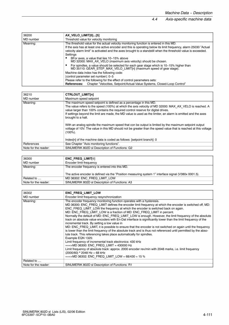
Machine Data − Description
4.4 Axis-specific machine data
4-111 SINUMERIK 802D sl Lists (LIS), 02/06 Edition6FC5397−5CP10−0BA0
36200 AX_VELO_LIMIT[0]...[5]MD number Threshold value for velocity monitoringMeaning: The threshold value for the actual velocity monitoring function is entered in this MD.
If the axis has at least one active encoder and this is operating below its limit frequency, alarm 25030 ”Actualvelocity alarm limit” is activated and the axes brought to a standstill when the threshold value is exceeded.Settings� BFor axes, a value that lies 10−15% above
MD 32000: MAX_AX_VELO (maximum axis velocity) should be chosen. � For spindles, a value should be selected for each gear stage which is 10−15% higher than
MD 35110: GEAR_STEP_MAX_VELO_LIMIT[n] (maximum speed of gear stage).Machine data index has the following code:[control parameter set number]: 0−5Please refer to the following for the effect of control parameters sets:References: Chapter ”Velocities, Setpoint/Actual-Value Systems, Closed-Loop Control”
36210 CTRLOUT_LIMIT[n]MD number Maximum speed setpointMeaning: The maximum speed setpoint is defined as a percentage in this MD.
The value refers to the speed (100%) at which the axis velocity of MD 32000: MAX_AX_VELO is reached. Avalue larger than 100% contains the required control reserve for digital drives.If settings beyond the limit are made, the MD value is used as the limiter, an alarm is emitted and the axesbrought to a halt.
With an analog spindle the maximum speed that con be output is limited by the maximum setpoint outputvoltage of 10V. The value in this MD should not be greater than the speed value that is reached at this voltage(100%).
Index[n] of the machine data is coded as follows: [setpoint branch]: 0References See Chapter ”Axis monitoring functions”.Note for the reader: SINUMERIK 802D sl Description of Functions: G2
36300 ENC_FREQ_LIMIT���MD number Encoder limit frequencyMeaning: The encoder frequency is entered into this MD.
The active encoder is defined via the ”Position measuring system 1” interface signal (V380x 0001.5).Related to .... MD 36302: ENC_FREQ_LIMIT_LOWNote for the reader: SINUMERIK 802D sl Description of Functions: A3
36302 ENC_FREQ_LIMIT_LOWMD number Encoder limit frequency resynchronizationMeaning: The encoder frequency monitoring function operates with a hysteresis.
MD 36300: ENC_FREQ_LIMIT defines the encoder limit frequency at which the encoder is switched off, MD:ENC_FREQ_LIMIT_LOW the frequency at which the encoder is switched back on again.MD: ENC_FREQ_LIMIT_LOW is a fraction of MD: ENC_FREQ_LIMIT in percent.Normally the default of MD: ENC_FREQ_LIMIT_LOW is enough. However, the limit frequency of the absolutetrack on absolute value encoders with En-Dat interface is significantly lower than the limit frequency of theincremental track. By setting a low value in MD: ENC_FREQ_LIMIT, it is possible to ensure that the encoder is not switched on again until the frequencyis lower than the limit frequency of the absolute track and is thus not referenced until permitted by the abso-lute track. This referencing takes place automatically for spindles.Example EQN 1325:Limit frequency of incremental track electronics: 430 kHz===>MD 36300: ENC_FREQ_LIMIT = 430000 HzLimit frequency of absolute track: approx. 2000 encoder rev/min with 2048 marks, i.e. limit frequency(2000/60) * 2048 Hz = 68 kHz===>MD 36302: ENC_FREQ_LIMIT_LOW = 68/430 = 15 %
Related to ....Note for the reader: SINUMERIK 802D sl Description of Functions: R1

4.4 Axis-specific machine data
Machine Data − Description
4-112SINUMERIK 802D sl Lists (LIS), 02/06 Edition
6FC5397−5CP10−0BA0
36310 ENC_ZERO_MONITORING���
MD number Zero-mark monitoringMeaning: This machine data activates the zero-mark monitoring and determines the number of inadmissible zero
marks.0: Zero-mark monitoring OFF, encoder hardware monitoring ON1−99, > 100: Number of identified zero-mark errors at which the monitoring
should be activated100: Zero-mark monitoring OFF, encoder hardware monitoring OFF
Examples: MD value = 1: monitoring is activated at the 1st error.MD value = 2: the 1st error is tolerated. Monitoring is activated at the 2nd error.MD value = 3: the 1st and 2nd errors are tolerated. Monitoring is activated at the 3rd error.The error count always begins at zero when the encoder is switched on.
Special cases, errors, ... ... The zero-mark monitoring on absolute value encoders must be switched off with value = 0! Note for the reader: SINUMERIK 802D sl Description of Functions: A3
36400 CONTOUR_TOLMD number Contour monitoring tolerance bandMeaning: Tolerance band for max. contour deviation.
The maximum difference between the real and expected actual value is entered in this MD.The input of a tolerance band is designed to prevent the contour monitoring function from responding erro-neously due to slight fluctuations in speed resulting from normal control procedures (e.g. during first cut).This MD must be adapted to the position controller gain and, in the case of feedforward control, to the accu-racy of the loop model MD 32810: EQUIV_SPEEDCTRL_TIME (equivalent time constant for speed loopfeedforward control) and to the permissible acceleration rates and velocities.
Note for the reader: SINUMERIK 802D sl Description of Functions: A3
36500 ENC_CHANGE_TOLMD number Backlash compensation partial section/tolerance for position actual value changeoverMeaning: Partial section when applying backlash compensation.
This MD is used to manage large backlash compensation values. It ensures that the backlash is not switchedthrough to the actual value all at once, but in n steps with an increment size as set in MD:ENC_CHANGE_TOL. Calculation of the backlash thus takes n servo cycles. If it takes too long to completecomputation of the backlash, zero speed monitoring alarms may be generated.
This MD only becomes effective if the MD: ENC_CHANGE_TOL is set higher than MD: BACK_LASH.Related to .... MD 32450: BACKLASH[0] (backlash compensation)Note for the reader: SINUMERIK 802D sl Description of Functions: K3
36600 BRAKE_MODE_CHOICEMD number Deceleration behavior on hardware limit switchMeaning: If a rising signal edge is detected at the axis-specific hardware limit switch, the axis is decelerated immedia-
tely.The type of deceleration is specified via machine data:
0: controlled deceleration according to the acceleration ramp defined by MD 32300: MAX_AX_ACCEL (axis acceleration).
1: fast deceleration (setpoint default = 0) with reduction of following error.Related to .... ”Hardware limit switch plus or minus” interface signal (V380x 1000.1 or V380x 1000.0)Note for the reader: SINUMERIK 802D sl Description of Functions: A3

Machine Data − Description
4.4 Axis-specific machine data
4-113 SINUMERIK 802D sl Lists (LIS), 02/06 Edition6FC5397−5CP10−0BA0
36610 AX_EMERGENCY_STOP_TIMEMD number Length of the braking ramp for error statesMeaning: For axis: when the following monitoring functions respond, the affected axis is brought to a standstill with
rapid stop (with open position control loop) along a braking ramp of the speed setpoint:� EMERGENCY STOP� Following error monitoring� Positioning monitoring� Zero-speed monitoring� Clamping monitoring� Speed setpoint monitoring� Actual velocity monitoring� Encoder limit frequency monitoring (except on speed-controlled spindles)� Zero-mark monitoring� Contour tunnel monitoringIf the encoder limit frequency is exceeded, the speed setpoint is displayed as the actual value in the basicNC display.The time for the reduction of the speed setpoint from the maximum speed setpoint to setpoint = 0 should beentered in MD 36610. The time taken to stop the axis depends on the actual speed setpoint at the time themonitoring responds.
Speed setpoint
MD 36210:CTRLOUT_LIMIT
e.g. currentspeed setpoint
Current time untilaxis stops
t [s]
MD 36610: AX_EMERGENCY_STOP_TIME
Fig. 4-1 Braking ramp for error statesFor spindle: In the case of spindles without an active position control, the speed-controlled spindle maycontinue to rotate with no rapid stop braking response when the encoder frequency monitoring function re-sponds (i.e. no valid actual value information available). The speed setpoint monitor is active, but not theactual velocity monitor (MD 36200) when the encoder is active. The spindle speed setpoint limit is just limited(no alarm); the setpoint is limited to the max. chuck speed (MD 35100) and displayed in IS ”Programmedspeed too high”.The current speed is not displayed as no valid actual value is available at this point in time
Meaning: Where interpolating axes are involved, maintenance of the contour during the deceleration phase cannot beguaranteed.
Notice: If the value for the duration of the braking ramp for error states has been set too high, controllerenable is canceled even though the axis/spindle is still traversing. It is then stopped abruptly withspeed setpoint 0. The time set in MD 36610: AX_EMERGENCY_STOP_TIME should therefore be less than the time set in MD36620: SERVO_DISABLE_DELAY_TIME (shutdown delay controller enable).
Related to .... MD 36620: SERVO_DISABLE_DELAY_TIME Shutdown delay servo enableMD 36210: CTRLOUT_LIMIT Maximum speed setpoint
Note for the reader: SINUMERIK 802D sl Description of Functions: A3

4.4 Axis-specific machine data
Machine Data − Description
4-114SINUMERIK 802D sl Lists (LIS), 02/06 Edition
6FC5397−5CP10−0BA0
36620 SERVO_DISABLE_DELAY_TIMEMD number Cutout delay servo enableMeaning: Maximum delay time for removal of ”controller enable” after a fault.
If the axis/spindle is still moving the speed enable (controller enable) of the drive is removed by the control atthe latest after the delay time set.The entered delay time is activated in the following events:
� For faults which cause the axes to stop immediately
� If IS ”controller enable” is removed by the PLCAs soon as the actual speed has reached the zero speed range (MD 36060: STANDSTILL_VELO_ TOL) ”Servo enable” is removed for the drive.The time set must be long enough to allow the axis/spindle to be brought to zero speed from maximum traver-sing velocity/speed.If the axis/spindle is stationary, ”controller enable” is removed for the drive immediately.
Application example(s) The drive speed control should be maintained long enough for the axis/spindle to come to a standstill frommaximum traversing speed. Removal of ”controller enable” for a moving axis/spindle must be delayed untilthis has happened.
Special cases, errors, ... ... Caution: If the setting for the controller enable shutdown delay is too small the servo enable will be removedeven though the axis/spindle is still moving. The axis/spindle is then stopped abruptly with setpoint 0.The time in this MD should therefore be greater than the duration of the brake ramp in error states (MD36610: AX_EMERGENCY_STOP_TIME).
Related to .... IS ”controller enable” (V380x 0002.1)MD 36610: AX_EMERGENCY_STOP_TIME (Time for braking ramp when an error occurs)
Note for the reader: SINUMERIK 802D sl Description of Functions: N2
36720 DRIFT_VALUEMD number Basic drift value for analog spindles only
Meaning: The basic drift value entered here is always applied as an additional speed setpoint value for the analogspindle.
MD irrelevant for ... ...Note for the reader: SINUMERIK 802D sl Description of Functions: S1
37000 FIXED_STOP_MODEMD number Travel to fixed stop modeMeaning: The machine data specifies how the ”Travel to fixed stop” function can be started.
Value =0: Travel to fixed stop not available.= 1: Travel to fixed stop may be started from the NC program using the command
FXS[x]=1.Note for the reader: SINUMERIK 802D sl Description of Functions: F1
37002 FIXED_STOP_CONTROLMD number Special function when traveling to fixed stopMeaning: Bit 0: Response for pulse inhibit at limit
=0: Travel to fixed stop is canceled.= 1: Travel to fixed stop is interrupted, i.e. the drive is rendered powerless.
As soon as the pulse block is canceled once more, the drive applies pressure again with the limited torque.The torque is applied abruptly.
Note for the reader: SINUMERIK 802D sl Description of Functions: F1

Machine Data − Description
4.4 Axis-specific machine data
4-115 SINUMERIK 802D sl Lists (LIS), 02/06 Edition6FC5397−5CP10−0BA0
37010 FIXED_STOP_TORQUE_DEFMD number Default for clamping torqueMeaning: The clamping torque is entered in this machine data as a percentage of the maximum motor torque (for FSD,
corresponds with percentage of max. current setpoint)
The clamping torque becomes operative as soon as the fixed stop is reached or IS ”Acknowledge fixed stop”has been set.
The entered value is a default and is effective only on the condition that� no clamping torque has been programmed with command FXST[x].� the clamping torque set in SD 43510: FIXED_STOP_TORQUE has not been changed
(after fixed stop was reached).Related to .... SD 43510: FIXED_STOP_TORQUE (clamping torque for travel to fixed stop)Note for the reader: SINUMERIK 802D sl Description of Functions: F1
37012 FIXED_STOP_TORQUE_RAMP_TIMEMD number Virtual time until reaching the new clamping torque when traveling to fixed stopMeaning: Virtual time until reaching the modified torque limit.
The subdivision is measured in the position controller cycle and applied abruptly.The value 0.0 deactivates the ramp function.
Note for the reader: SINUMERIK 802D sl Description of Functions: F1
37020 FIXED_STOP_WINDOW_DEFMD number Default for fixed stop monitoring windowMeaning: The default setting for the fixed stop monitoring window is set in this machine data.
The fixed stop monitoring window becomes operative as soon as the fixed stop is reached, i.e. IS ”Fixed stopreached” is set.
If the axis/spindle leaves the position at which the fixed stop has been detected by more than the tolerancespecified in MD: FIXED_STOP_WINDOW_DEF, then alarm 20093 ”Fixed stop monitoring has responded” isoutput and the ”FXS” function deselected.
The entered value is a default and is effective only on the condition that� no fixed stop monitoring window has been programmed with command FXSW[x]� the fixed stop monitoring window set via SD 43520: FIXED_STOP_WINDOW has not been changed
(after fixed stop was reached).Related to .... SD 43520: FIXED_STOP_WINDOW (fixed stop monitoring window)Note for the reader: SINUMERIK 802D sl Description of Functions: F1
37030 FIXED_STOP_THRESHOLDMD number Threshold for fixed stop detectionMeaning: The contour monitoring threshold for fixed stop detection is entered in this machine data.
This machine data is effective only if MD: FIXED_STOP_BY_SENSOR is set to 0.
IS ”Fixed stop reached” is set if the axis-specific contour deviation exceeds the threshold set in MD:FIXED_STOP_THRESHOLD.
MD irrelevant for ... ... MD 37040: FIXED_STOP_BY_SENSOR = 1Related to .... IS ”Fixed stop reached” Note for the reader: SINUMERIK 802D sl Description of Functions: F1

4.4 Axis-specific machine data
Machine Data − Description
4-116SINUMERIK 802D sl Lists (LIS), 02/06 Edition
6FC5397−5CP10−0BA0
37040 FIXED_STOP_BY_SENSORMD number Fixed stop detection via sensorMeaning: The machine data specifies how the ”Fixed stop reached” criterion
is determined.Value =0: The ”Fixed stop reached” criterion is determined internally based on the axis-specific
contour deviation (threshold specified by MD: FIXED_STOP_THRESHOLD).= 1: The ”Fixed stop reached” criterion is determined via an external sensor and
the NC is notified via IS ”Fixed stop sensor”.=2: The ”Fixed stop reached” criterion is accepted provided either the
contour monitoring function (setting = 0) or the signal from the external sensor (setting = 1) has responded.
Related to .... MD 37030: FIXED_STOP_THRESHOLD (threshold for fixed stop detection)IS ”Sensor for fixed stop”
Note for the reader: SINUMERIK 802D sl Description of Functions: F1
37050 FIXED_STOP_ALARM_MASKMD number Enabling the fixed stop alarmsMeaning: The machine data specifies whether the alarm
20091 ”Fixed stop not reached” and20094 ”Fixed stop aborted” will be generated.Value = 0: suppress alarm 20091 ”Fixed stop not reached”
= 2: suppress alarms 20091 ”Fixed stop not reached” and20094 ”Fixed stop aborted”
= 3: suppress alarm 20094 ”Fixed stop aborted”
All other permissible values of � 7 do not suppress any alarms.Note for the reader: SINUMERIK 802D sl Description of Functions: F1
37060 FIXED_STOP_ACKN_MASKMD number Monitoring of PLC acknowledgments for travel to fixed stopMeaning: This machine data determines whether or not the NC waits for acknowledgment
messages from the PLC when the ”Travel to fixed stop” function is active.
Bit 0 = 0: Once the NC has transmitted IS ”Activate travel to fixed stop” to the PLC, it starts theprogrammed travel motion.
Bit 0 =1: After the NC has transferred IS ”Activate travel to fixed stop” to the PLC, it waits for the PLC toacknowledge with IS ”Enable travel to fixed stop” and then starts the programmed travel motion.
Bit 1 = 0: Once the NC has transferred IS ”Fixed stop reached” to the PLC, the program advances to thenext block.
Bit 1 = 1: After the NC has transferred IS ”Fixed stop reached” to the PLC, it waits for the PLC toacknowledge with IS ”Acknowledge fixed stop reached”, outputs the programmed torque andthen executes a block change.
Related to .... IS ”Activate travel to fixed stop” IS ”Enable travel to fixed stop” IS ”Fixed stop reached” IS ”Acknowledge fixed stop reached”
Note for the reader: SINUMERIK 802D sl Description of Functions: F1
37400 EPS_TLIFT_TANG_STEPMD number Tangential angle for corner recognitionMeaning: If TLIFT has been programmed and the axis is under tangential follow-up control (tracking), a step change in
the position setpoint which is larger than the value of this MD causes an intermediate block to be inserted.The intermediate block moves the axis to the position corresponding to the initial tangent in the next block.
MD irrelevant for ... ... TLIFT not activatedRelated to .... TLIFT instructionNote for the reader: SINUMERIK 802D sl Description of Functions: T3

Machine Data − Description
4.4 Axis-specific machine data
4-117 SINUMERIK 802D sl Lists (LIS), 02/06 Edition6FC5397−5CP10−0BA0
37402 TANG_OFFSETMD number Default angle for tangential follow-up controlMeaning: Default offset (angle) which the following axis forms with the tangent.
The angle acts additively to the angle programmed in the TANGON block.MD irrelevant for ... ... if no tangential follow-up controlRelated to .... TANGON instructionNote for the reader: SINUMERIK 802D sl Description of Functions: T3
38000 MM_ENC_COMP_MAX_POINTS[n] (MD can only be displayed!)MD number Interpolation points for encoder/spindle compensation (LEC )Meaning: For leadscrew error compensation, the maximum number of interpolation points per axis/measuring system is
125.The required number k can be calculated as follows using the defined parameters:
$AA_ENC_COMP_MAX−$AA_ENC_COMP_MIN
k = −−−−−−−−−−−−−−−−−−−−−−−−−−−−−−−−−−−−−−−−−−− + 1$AA_ENC_COMP_STEP
$AA_ENC_COMP_MIN Initial position (system variable)$AA_ENC_COMP_MAX End position (system variable)$AA_ENC_COMP_STEP Distance betw. interpolation points (system variable)
Index[n] has the following coding: [encoder no.]: 0Related to .... MD 32700: ENC_ COMP_ ENABLE[n] Interpolatory compensation activeNote for the reader: SINUMERIK 802D sl Description of Functions: K3

4.4 Axis-specific machine data
Machine Data − Description
4-118SINUMERIK 802D sl Lists (LIS), 02/06 Edition
6FC5397−5CP10−0BA0
This sheet has been left empty for your notes.

5-119 SINUMERIK 802D sl Lists (LIS), 02/06 Edition6FC5397−5CP10−0BA0
Setting Data − Description
5.1 General setting data
41010 JOG_VAR_INCR_SIZESD number Size of variable increment for INC/handwheelMeaning: This setting data defines the number of increments when variable increment (INCvar) is selected. This incre-
ment size is traversed by the axis in JOG mode whenever the traverse key is pressed or the handwheel isturned one detent position and variable increment is selected (”Active machine function: INC variable” inter-face signal for machine or geometry axes is set to 1).Note: Please note that the increment size is active for incremental jogging and handwheel jogging.
SD irrelevant for ... ... If INCvar not activeRelated to .... IS ”Active machine function: INCvariable” (V3200 1001.5, V3200 1005.5, V3200 1009.5, V380x 0005.5)Note for the reader: SINUMERIK 802D sl Description of Functions: H1
41110 JOG_SET_VELOSD number JOG velocity for linear axes (for G94)Meaning: Value > 0:
The velocity entered applies to all linear axes in JOG mode if they are traversed manually using the ”traver-sing keys plus and minus”.The axis velocity setting is active for:
− Continuous traversing− Incremental traversing (INC1, ..., INCvar)
The value entered may not exceed the maximum permissible axis velocity (MD 32000: MAX_AX_VELO).
Value = 0:The feedrate in JOG mode is the corresponding axis-specific MD 32020: JOG_VELO ”JOG axis velocity”. Inthis way, it is possible to define a separate JOG velocity for every axis.
SD irrelevant for ... ... − For rotary axes (SD 41130: JOG_ROT_AX_SET_VELO) appliesRelated to .... Axis−specific MD 32020: JOG_VELO (JOG axis velocity)
Axis−specific MD 32000: MAX_AX_VELO (maximum axis velocity)SD 41130: JOG_ROT_AX_SET_VELO (JOG velocity for rotary axes)
Note for the reader: SINUMERIK 802D sl Description of Functions: H1
41130 JOG_ROT_AX_SET_VELOSD number JOG velocity for rotary axesMeaning: As for SD 41110: JOG_AX_SET_VELO − but for all rotary axes instead of linear axesApplication example(s) The operator can define a JOG velocity for a particular application.Related to .... MD 32020: JOG_VELO (JOG axis velocity)
MD 32000: MAX_AX_VELO (maximum axis velocity)Note for the reader: SINUMERIK 802D sl Description of Functions: H1
5

5.1 General setting data
Setting Data − Description
5-120SINUMERIK 802D sl Lists (LIS), 02/06 Edition
6FC5397−5CP10−0BA0
41200 JOG_SPIND_SET_VELOSD number JOG speed for spindlesMeaning: Value > 0:
The velocity entered applies to spindles in JOG mode if they are traversed manually using the ”traversingkeys plus and minus”.The velocity setting is active for:
− Continuous jogging− Incremental jogging (INC1, ..., INCvar)
The value entered must not exceed the maximum permissible velocity (MD 32000: MAX_AX_VELO).
Value = 0:If 0 has been entered in the setting data, the active JOG velocity is MD 32020: JOG_VELO (JOG axis velocity). Each axis can be given its own JOG velocity with this MD (axis-specific MD).When the spindle is traversed in JOG mode, the maximum velocity of the active gear stage (MD 35130:GEAR_STEP_MAX_VELO_LIMIT) is taken into account.
SD irrelevant for ... ... AxesRelated to .... MD 32020: JOG_VELO (JOG axis velocity)
MD 35130: GEAR_STEP_MAX_VELO_LIMIT (maximum velocity of gear stages)Note for the reader: SINUMERIK 802D sl Description of Functions: H1, S1

Setting Data − Description
5.2 Channel-specific setting data
5-121 SINUMERIK 802D sl Lists (LIS), 02/06 Edition6FC5397−5CP10−0BA0
5.2 Channel-specific setting data
42000 THREAD_START_ANGLE
SD number Start angle for thread G33
Meaning: This setting data can be used to program the offset of the individual threads when cutting multiple threads.This SD can be changed from the part program by the SF=... command. If no SF=... is written in the G33block of the part program, then the setting data applies.
Further references ”Operation and Programming”Note for the reader: SINUMERIK 802D sl Description of Functions: K1
42010 THREAD_RAMP_DISP[n] (Index n = 0: run-up distance, n=1: Deceleration path)SD number Starting and deceleration behavior of feed axis in thread cutting G33Meaning: The SD is effective for thread cutting with G33, G34, G35. It provides two elements that determine the beha-
vior during the starting of the thread axis (1st element = index 0) and during the braking with rounding (2ndelement = index 1).The values possess the same properties for the thread run-in and run-out:−1: Starting/braking of the thread axis is carried out with the configured acceleration.
Jerk according to current BRISK/SOFT programming.
0: Abrupt starting/braking of the feedrate axis during thread cutting. > 0: The maximum thread starting/braking distance is defined. The defined distance may
cause an acceleration overload of the axis. The SD is defined during the programming of DITR (Displacement Thread Ramp) from the block.
The default values (−1) for both elements of the SD are set with NC reset and at the end of the part program.Example: $SC_THREAD_RAMP_DISP[0]=2 ; run-in path 2 mm
The SD is defined during the programming of DITS (index 0) and DITE (index 1) from the block.SD irrelevant for ... ... no G33, G34, G35Related to .... With the DITS and DITE (Displacement Thread Start/End) part program instructions.Note for the reader: SINUMERIK 802D sl Description of Functions: K1, V1
42100 DRY_RUN_FEED
SD number Dry run feedrate
Meaning: To check a part program with regard to the traversing path (without workpiece to be machined) the operatorcan activate the dry run feed function on the operator interface (Program control softkey). The value of thissetting data is then taken instead of the programmed feed value. Rapid traverse feed values are not chan-ged. The dry run feedrate value can be entered in the Setting data menu.The function is effective only in the AUTOMATIC and MDA modes.
SD irrelevant for ... ... Dry run feedrate function not activated
Application example(s) Checking traversing distances with new part programs
Special cases, errors, ......
The function may not be activated if a workpiece should be machined. The maximum cutting speed of thetool might be exceeded by the activated dry run feedrate. The destruction of the workpiece and of the toolcould be the consequence.
Note for the reader: SINUMERIK 802D sl Description of Functions: K1
42110 DEFAULT_FEEDSD number Default value for path feedrateMeaning: The setting date is evaluated during the start of the part program with consideration of the switch-on position
of the feedrate type.Switch-on positions:
Turning: G95 − feedrate in mm/rev. of the spindleMilling: G94 − feedrate in mm/min
If no F word is written at G1, G2, G2, ... for the applicable feedrate type and if the SD value is not zero, thefeedrate from this SD is used. Otherwise, an alarm indicating the missing feedrate is issued.
SD irrelevant for ... ... Turning: G94 programmedMilling: G95 programmed
Note for the reader: SINUMERIK 802D sl Description of Functions: V1

5.2 Channel-specific setting data
Setting Data − Description
5-122SINUMERIK 802D sl Lists (LIS), 02/06 Edition
6FC5397−5CP10−0BA0
42940 TOOL_LENGTH_CONSTSD number Retain the assignment of tool lengths 1 to 3 to the geo-axes when changing the machining plane (G17 to
G19)
Meaning: If this setting data is not zero, the allocation of the tool lengths 1 to 3(length, wear) to the geometry axes is not changed if the machining plane (G17 to G19) changes. The alloca-tion of tool length components to the geometry axes results from the value of the setting data according to thefollowing tables. With respect to the allocation, a distinction is made between turning tools (tool types 500 to599) and other tools (drilling/milling tools). For the representation in the tables it is assumed that geometryaxes 1 to 3 are named X, Y, Z. However, the geometry axis sequence, and not the axis identifier, is the deter-mining factor in the assignment of an offset to an axis.The assignment of the tool lengths to the geometry axes for turning tools (tool types 500 to599) results from the value of setting data SD 42940 in accordance with the following table:Plane/value Length 1 Length 2 Length 317 Y X Z18*) X Z Y19 Z Y X−17 X Y Z−18 Z X Y−19 Y Z X
The following table shows the allocation of the tool lengths 1 to 3 to the geometry axes fordrills/milling cutters (tool types 100 to 299):Plane/value Length 1 Length 2 Length 317*) Z Y X18 Y X Z19 X Z Y−17 Z X Y−18 Y Z X−19 X Y Z
Related to .... SD 42950: TOOL_LENGTH_TYPENote for the reader: SINUMERIK 802D sl Description of Functions: W1
42950 TOOL_LENGTH_TYPESD number Allocation of the tool length compensation independent of tool typeMeaning: 0: The assignment is performed by default. A distinction is made between turning tools (tool type 500 to
599) and drilling/milling tools (tool type 100 to 299).
Related to .... SD 42940: TOOL_LENGTH_CONSTNote for the reader: SINUMERIK 802D sl Description of Functions: W1

Setting Data − Description
5.3 Spindle-specific setting data
5-123 SINUMERIK 802D sl Lists (LIS), 02/06 Edition6FC5397−5CP10−0BA0
5.3 Spindle-specific setting data
43210 SPIND_MIN_VELO_G25SD number Programmable lower spindle speed limiting for G25Meaning: The spindle speed is not permitted to drop below the minimum spindle speed limit entered in this SD. The
NCK limits an excessively small spindle speed setpoint to this value.The spindle speed can only fall below the minimum limit through:
� Spindle override 0%� M5� S0� IS ”Spindle stop” (V380x 0004.3)� IS ”Controller enable” (V380x 0002.1)� IS ”Reset” (V3000 0000.7)� IS ”Spindle reset” (V380x 0002.2)� IS ”Oscillation speed” (V380x 2002.5
SD irrelevant for ... ... All spindle modes except control modeSpecial cases, errors, ... ... The value in SD: SPIND_MIN_VELO_G25 can be altered by means of:
� G25 S .... in the part program� Operator commands from the HMIThe value in SD: SPIND_MIN_VELO_G25 is retained after reset or power off.
Related to .... SD 43220: SPIND_MAX_VELO_G26SD 43230: SPIND_MAX_VELO_LIMS (progr. Spindle speed limiting with G96)
Note for the reader: SINUMERIK 802D sl Description of Functions: S1
43220 SPIND_MAX_VELO_G26SD number Programmable upper spindle speed limiting for G26Meaning: The spindle speed is not permitted to exceed the maximum spindle speed limit entered in this SD. The NCK
limits an excessive spindle speed setpoint to this value.SD irrelevant for ... ... All spindle modes except control mode.Special cases, errors, ... ... The value in this SD: SPIND_MIN_VELO_G26 can be altered by means of:
� G26 S .... in the part program
� Operator commands from the HMIThe value in SD: SPIND_MIN_VELO_G26 is retained after reset or power off.
Related to .... SD 43210: SPIND_MIN_VELO_G25 (progr. spindle speed limiting G25)SD 43230: SPIND_MAX_VELO_LIMS (progr. Spindle speed limiting with G96)
Note for the reader: SINUMERIK 802D sl Description of Functions: S1
43230 SPIND_MAX_VELO_LIMSSD number progr. Spindle speed limiting G96Meaning: At constant cutting rate (G96 and G97) an extra limits entered in SPIND_MAX_VELO_LIMS is operative in
addition to the continually applied limits. Furthermore this can be described with SPIND_MAX_VELO_LIMS inthe part program with LIMS=... .
SD irrelevant for ... ... All spindle functions except for G96 and G97 (constant cutting speed)Application example(s) When cutting-off and for very small diameters of the workpiece to be machined, the spindle with the work-
piece (lathe) accelerates higher and higher at a constant cutting rate (G96), theoretically reaching an infinitelyhigh set speed in the position of the traverse axis X=0. In cases such as this, the spindle rotates up to itsmaximum spindle speed in the current gear stage (limited, where applicable, by G26). If, especially for G96,the spindle is to be limited to a lower speed, then this can be defined using LIMS=....SPIND_MAX_VELO_LIMS.
Special cases, errors, ... ... The value SD 43210: SPIND_MIN_VELO_LIMS can be changed using:
� LIMS S .... in the part program
� Operator commands from the HMIThe value SD SPIND_MIN_VELO_LIMS is retained after reset or power down.
Related to .... SD 43220: SPIND_MAX_VELO_G26 (maximum spindle speed)SD 43210: SPIND_MIN_VELO_G25 (minimum spindle speed)
Note for the reader: SINUMERIK 802D sl Description of Functions: S1

5.3 Spindle-specific setting data
Setting Data − Description
5-124SINUMERIK 802D sl Lists (LIS), 02/06 Edition
6FC5397−5CP10−0BA0
43400 WORKAREA_PLUS_ENABLESD number Working area limiting active in positive directionMeaning: 0: The working area limit of the axis is deactivated in the positive direction.
1: The working area limit of the axis is active in the positive direction.The setting data is parameterized using the operator panel in the ”Parameter” area by activating/deactivatingthe working area limitation.
SD irrelevant for ... ... G−Code: WALIMOFNote for the reader: SINUMERIK 802D sl Description of Functions: A3
43410 WORKAREA_MINUS_ENABLESD number Working area limiting active in negative directionMeaning: 0: The working area limit of the axis is deactivated in the negative direction.
1: The working area limit of the axis is active in the negative direction.The setting data is parameterized using the operator panel in the ”Parameter” area by activating/deactivatingthe working area limitation.
SD irrelevant for ... ... G−Code: WALIMOFNote for the reader: SINUMERIK 802D sl Description of Functions: A3
43420 WORKAREA_LIMIT_PLUSSD number Working area, limiting plusMeaning: The working area limits can be used to restrict the working area in the MCS in the positive direction of the
corresponding axis.The setting data can be changed via the operator panel in the ”Parameter” operating area.The positive working area limit can be changed in the program with G26.
SD irrelevant for ... ... G−Code: WALIMOFRelated to .... SD 43400: WORKAREA_PLUS_ENABLENote for the reader: SINUMERIK 802D sl Description of Functions: A3
43430 WORKAREA_LIMIT_MINUSSD number Working area, limiting minusMeaning: The working area limitation can be used to restrict the working area in the MCS in the negative direction of
the corresponding axis.The setting data can be changed via the operator panel in the ”Parameter” operating area.The negative working area limit can be changed in the program with G25.
SD irrelevant for ... ... G code: WALIMOFRelated to .... SD 43410: WORKAREA_MINUS_ENABLENote for the reader: SINUMERIK 802D sl Description of Functions: A3
43500 FIXED_STOP_SWITCHSD number Selection of travel to fixed stopMeaning: This setting data allows the ”Travel to fixed stop” function to be checked.
Value =0: Deselect ”Travel to fixed stop” function=1: Select ”Travel to fixed stop” function
The setting data can be overwritten by the part program using the command FXS[x]=1/0.Note for the reader: SINUMERIK 802D sl Description of Functions: F1

Setting Data − Description
5.3 Spindle-specific setting data
5-125 SINUMERIK 802D sl Lists (LIS), 02/06 Edition6FC5397−5CP10−0BA0
43510 FIXED_STOP_TORQUESD number Clamping torque for travel to fixed stopMeaning: The clamping torque is entered in this setting data as a percentage of the maximum
motor torque (for FSD, corresponds with percentage of max. current setpoint)
Please note that a clamping torque greater than 100% may only be present for a short time; otherwise, the motor will be damaged
When selecting the function ”Travel to fixed stop” through programming FXS[.]the default setting of the MD 37010: FIXED_STOP_TORQUE_DEF applies until it is programmed with FXST[.].The FXST[x] command acts like a block-synchronous change of this setting data.The setting data can be modified by the operator. The SD is already operative as the stop is approached.
The fixed stop is considered reached if: FIXED_STOP_ACKN_MASK,bit 1 = 0, with MD37060: (no acknowledgment required) IS ”Fixed stop reached” is set
by the NC.Bit 1 = 1: (acknowledgment required) IS ”Fixed stop reached” is set by the NC
and acknowledged by IS ”Acknowledge fixed stop reached”.Related to .... MD 37010: FIXED_STOP_TORQUE_DEF (default setting for clamping torque)Note for the reader: SINUMERIK 802D sl Description of Functions: F1

5.3 Spindle-specific setting data
Setting Data − Description
5-126SINUMERIK 802D sl Lists (LIS), 02/06 Edition
6FC5397−5CP10−0BA0
This sheet has been left empty for your notes.

6-127 SINUMERIK 802D sl Lists (LIS), 02/06 Edition6FC5397−5CP10−0BA0
Interface Signals
6.1 General
Interfaces
The exchange of signals and data between the PLC user program and
� NCK (core of numerical control)
� HMI (display unit)
takes places through various data areas. The PLC user program does not have to handlethe exchange of data and signals. From the users point of view, this takes place automati-cally.
Signals from NCK
Signals to NCK
NCK
General
Operating modes
Axis,Spindle
Userprogram
PLCGeneral
Signals to NC
Signals from NC
Channel
Operating modes
Signals to NCK
Signals from NCK
Channel
Signals to NCK
Signals from NCK
Spindle (n+1)Axis n
Axis 2Axis 1
Signals to NCK
Signals from NCK
Fig. 6-1 PLC/NCK interface
6

6.1 General
Interface Signals
6-128SINUMERIK 802D sl Lists (LIS), 02/06 Edition
6FC5397−5CP10−0BA0
Cyclical signal exchange
The control and status signals of the PLC/NCK interface are updated cyclically.
The signals can be subdivided into the following groups (see Fig. 6-1):
� General signals
� Operating mode signals
� Channel signals
� Axis/spindle signals

Interface Signals
6.2 Signals from/to HMI
6-129 SINUMERIK 802D sl Lists (LIS), 02/06 Edition6FC5397−5CP10−0BA0
6.2 Signals from/to HMI
6.2.1 Program−control signals from HMI
V1700 0000.5 M01 selectedInterface signal Signal(s) from HMI −−−> PLCEdge evaluation: no Signal(s) updated: cyclic Signal(s) valid from SW:Signal state 1 or signaltransition 0 −−−> 1
Program control Activate M1 has been selected on the operator interface. This does not activate the func-tion.
Signal state 0 or signaltransition 1 −−−> 0
Program control Activate M1 has not been selected via the operator interface.
Related to .... IS ”Activate M01” IS ”M0/M1 active”
Note for the reader: 802D sl Description of Functions: K1
V1700 0000.6 Dry run feedrate selectedInterface signal Signal(s) from HMI −−−> PLCEdge evaluation: no Signal(s) updated: cyclic Signal(s) valid from SW:Signal status 1 or edge tran-sition 0 −−−> 1
Dry run feedrate is selected.Instead of the programmed feedrate, the dry run feedrate entered in SD 42100: DRY_RUN_FEED is effec-tive.When activating the dry run feedrate, the signal is automatically entered in the PLC interface and transferredby the PLC basic program to the PLC interface signal ”Activate dry run feedrate”.
Signal status 0 or edge tran-sition 1 −−−> 0
Dry run feedrate is not selected.The programmed feedrate is effective.
Related to .... IS ”Activate dry run feedrate” (V3200 0000.6)SD: DRY_RUN_FEED (dry run feedrate)
Note for the reader: 802D sl Description of Functions: V1, K1
V1700 0001.3 Feed override for rapid traverse selectedInterface signal Signal(s) from HMI −−−> PLCEdge evaluation: no Signal(s) updated: cyclic Signal(s) valid from SW:Signal status 1 or edge tran-sition 0 −−−> 1
The feedrate override switch is also to act as a rapid traverse override switch.Overrides more than 100 % are limited to the maximum value of 100 % rapid traverse override.The interface signal (IS) ”Feedrate override selected for rapid traverse” is automatically entered in the PLCinterface by the operator panel and transferred by the PLC basic program to the PLC interface signal ”Rapidtraverse override effective”.Furthermore, the IS ”Feedrate override” (VB3200 0004) is copied by the PLC basic program into the IS”Rapid traverse override” (VB3200 0005).
Signal state 0 or signaltransition 1 −−−> 0
Program control −Feed override for rapid traverse− has not been selected via the operator interface.
Application example(s) This signal is used if no separate rapid traverse override switch exists.Note for the reader: 802D sl Description of Functions: V1
V1700 0001.7 Program test selectedInterface signal Signal(s) from HMI −−−> PLCEdge evaluation: no Signal(s) updated: cyclic Signal(s) valid from SW:Signal state 1 or signaltransition 0 −−−> 1
Program control Program test has been selected via the operator interface. This does not activate thefunction.
Signal state 0 or signaltransition 1 −−−> 0
Program control Program test has not been selected via the operator interface.
Related to .... IS ”Activate program test” IS ”Program test active”
Note for the reader: 802D sl Description of Functions: K1

6.2 Signals from/to HMI
Interface Signals
6-130SINUMERIK 802D sl Lists (LIS), 02/06 Edition
6FC5397−5CP10−0BA0
V1700 0002V1700 0003.0 to .1
Skip block selectedrogram test selected””#
Interface signal Signal(s) from HMI −−−> PLCEdge evaluation: no Signal(s) updated: cyclic Signal(s) valid from SW:Signal state 1 or signaltransition 0 −−−> 1
Program control −skip block− has been selected via the operator interface. This does not activate thefunction.
Signal state 0 or signaltransition 1 −−−> 0
Program control −skip block− has not been selected via the operator interface.
Related to .... IS ”Activate skip block”Note for the reader: 802D sl Description of Functions: K1
V1700 0003.7 *** Measuring in JOG activeInterface signal Signal(s) to PLC (HMI −−−> PLC)Edge evaluation: no Signal(s) updated: cyclic Signal(s) valid from SW: 1.1Signal state 1 or signaltransition 0 −−−> 1
The ”Tool measuring in JOG” function is activated by HMI.Note: This signal remains set when changing to AUTOMATIC mode in this function. The HMI maintains theJOG image in the display. Only the active mode display changes.
Signal state 0 or signaltransition 1 −−−> 0
The ”Tool measuring” function is not active.
Note for the reader: 802D sl Description of Functions: M5
6.2.2 Signals from HMI
V1800 0000.0 AUTOMATIC modeInterface signal Signal(s) to PLC (HMI −−−> PLC)Edge evaluation: yes Signal(s) updated: cyclic Signal(s) valid from SW: 1.1Signal state 1 or signaltransition 0 −−−> 1
AUTOMATIC mode has been selected by the HMI.The signal status 1 is active for only one PLC cycle.
Signal state 0 AUTOMATIC mode is not selected by the HMI.Signal irrelevant for ... ... if ”Change mode disable” signalNote for the reader: 802D sl Description of Functions: M5
V1800 0000.1 MDA modeInterface signal Signal(s) to PLC (HMI −−−> PLC)Edge evaluation: yes Signal(s) updated: cyclic Signal(s) valid from SW: 1.1Signal state 1 or signaltransition 0 −−−> 1
MDA mode has been selected by the HMI.The signal status 1 is active for only one PLC cycle.
Signal state 0 MDA mode is not selected by the HMI.Signal irrelevant for ... ... if ”Change mode disable” signalNote for the reader: 802D sl Description of Functions: M5
V1800 0000.2 JOG modeInterface signal Signal(s) to PLC (HMI −−−> PLC)Edge evaluation: yes Signal(s) updated: cyclic Signal(s) valid from SW: 1.1Signal state 1 or signaltransition 0 −−−> 1
JOG mode has been selected by the HMI.The signal status 1 is active for only one PLC cycle.
Signal state 0 JOG mode is not selected by the HMI.Signal irrelevant for ... ... if ”Change mode disable” signalNote for the reader: 802D sl Description of Functions: M5

Interface Signals
6.2 Signals from/to HMI
6-131 SINUMERIK 802D sl Lists (LIS), 02/06 Edition6FC5397−5CP10−0BA0
V1800 0000.4 Mode group changeover disableInterface signal Signal(s) to PLC (HMI −−−> PLC)Edge evaluation: yes Signal(s) updated: cyclic Signal(s) valid from SW: 1.1Signal state 1 or signaltransition 0 −−−> 1
Request by MMC: The current active mode (JOG, MDA or AUTOMATIC) should not be changed. The signal status is active for only one PLC cycle.
Signal state 0 The mode can be changed.Note for the reader: 802D sl Description of Functions: M5
V1800 0000.6 *** Start measuring in JOGInterface signal Signal(s) to PLC (HMI −−−> PLC)Edge evaluation: yes Signal(s) updated: cyclic Signal(s) valid from SW: 1.1Signal state 1 or signaltransition 0 −−−> 1
Request to PLC by HMI to start the measuring program with NC start.The signal status 1 is active for only one PLC cycle only.
Signal state 0Note for the reader: 802D sl Description of Functions: M5
V1800 0001.2 Machine function REFInterface signal Signal(s) to PLC (HMI −−−> PLC)Edge evaluation: yes Signal(s) updated: cyclic Signal(s) valid from SW: 1.1Signal state 1 or signaltransition 0 −−−> 1
The REF machine function is selected from within JOG mode.The signal status 1 is active for only one PLC cycle only.
Signal state 0 Machine function REF is not selected.Signal irrelevant for ... ... if JOG mode is not active.Note for the reader: 802D sl Description of Functions: M5
6.2.3 Signals from operator panel
V1900 0000.6 Simulation activeInterface signal Signal(s) from HMI −−−> PLCEdge evaluation: no Signal(s) updated: cyclic Signal(s) valid from SW:Signal state 1 or signaltransition 0 −−−> 1
The −simulation− function has been selected via the operator interface.
Signal state 0 or signaltransition 1 −−−> 0
The −simulation− function has not been selected via the operator interface.
Related to ....Note for the reader: 802D sl Description of Functions: K1
6.2.4 General selection/status signals from HMI
V1900 0003.7 V1900 0004.7
Machine axis for handwheel 1for handwheel 2
Interface signal Signal(s) from NC (HMI −> PLC)Edge evaluation: no Signal(s) updated: cyclic Signal(s) valid from SW:Signal state 1 or signal tran-sition 0 −−−> 1
The operator has assigned an axis to the handwheel (1, 2, 3) directly on the operator panel. This axis is amachine axis − not a geometry axis (axis in the WCS).For further information see IS ”Axis number”.
Signal state 0 or signal tran-sition 1 −−−> 0
The operator has assigned an axis to the handwheel (1, 2, 3) directly on the operator panel. This axis is ageometry axis (axis in the WCS).For further information see IS ”Axis number”.
Related to .... IS ”Axis number” (V1900 0003.0 to .4, ff)Note for the reader: 802D sl Description of Functions: H1

6.2 Signals from/to HMI
Interface Signals
6-132SINUMERIK 802D sl Lists (LIS), 02/06 Edition
6FC5397−5CP10−0BA0
V1900 1003.0 to .2V1900 1004.0 to .2
Axis number for handwheel 1for handwheel 2
Interface signal Signal(s) from NC (HMI −> PLC)Edge evaluation: no Signal(s) updated: cyclic Signal(s) valid from SW:Significance of signal The operator can assign an axis to every handwheel directly via the operator panel. To do so, he defines the
required axis (e.g. X).The PLC user interface provides the number of the axis plus the information ’machine axis or geometry axis’(”machine axis” interface signal) as HMI interface signals.The ”Activate handwheel” interface signal for the defined axis must be set from the PLC user program.Depending on the setting in the HMI interface signal ”machine axis”, either the interface for the geometry axisor for the machine axis is used.The following must be noted when assigning the axis designation to the axis number:� IS ”Machine axis” = 1; i.e. machine axis − not geometry axis:
The assignment is made via MD 10000: AXCONF_MACHAX_NAME_TAB[n] (machine axis name).
� IS ”Machine axis” = 0; i.e. geometry axis (axis in WCS):The assignment is made via MD 20060: AXCONF_GEOAX_NAME_TAB[n](geometry axis name in channel). IS ”Channel number geometry axis handwheel n” defines the channelassigned to the handwheel.
The following coding applies to the axis number:Bit 2 Bit 1 Bit 0 axis number0 0 0 −0 0 1 10 1 0 20 1 1 31 0 0 41 0 1 5
Note: Bit 3 and bit 4 must always be left with value =0.
Related to ....IS ”Machine axis” (V1900 1003.7 ff)IS ”Activate handwheel” 1 to 3 /geometry axes 1, 2, 3
(V3200 1000.0 to .2, V3200 1004.0 to .2, V3200 1008.0 to .2)IS ”Activate handwheel” 1 to 3 /machine axes (V380x 0004.0 to .2)MD 10000: AXCONF_MACHAX_NAME_TAB [n] (machine axis name)MD 20060: AXCONF_GEOAX_NAME_TAB[n] (name of the geometry axis in the channel)
Note for the reader: 802D sl Description of Functions: H1
6.2.5 General selection/status signals to HMI
V1900 5001.0 Update the tool listInterface signal Signal(s) from channel (PLC −−−> HMI)Edge evaluation: yes Signal(s) updated: cyclic Signal(s) valid from SW:Signal state 1 or signaltransition 0 −−−> 1
Tool display is updated
Signal state 0 or signaltransition 1 −−−> 0
No effect
Note for the reader: 802D sl Description of Functions: W1
V1900 5002.0 Enabling machine tool measuring in JOGInterface signal Signal(s) from NCK (PLC → HMI)Edge evaluation: no Signal(s) updated: cyclic Signal(s) valid from SW: 2Signal state 1 or signal tran-sition 0 −−−> 1
Measuring in JOG function can be activated.
Signal state 0 or signal tran-sition 1 −−−> 0
Measuring in JOG is not possible.
Note for the reader: 802D sl Description of Functions: M5

Interface Signals
6.2 Signals from/to HMI
6-133 SINUMERIK 802D sl Lists (LIS), 02/06 Edition6FC5397−5CP10−0BA0
VD1900 5004 Tool number for tool measuring in JOGInterface signal Signal(s) to HMI (PLC −−−> HMI)Edge evaluation: no Signal(s) updated: cyclic Signal(s) valid from SW: 1.1Value > 0 (DWORD) Input of T number from PLC for entering measurement results to HMI. The number entered in the HMI
screen is used as offset number D.Value = 0 No specification of the T no. by PLCSignal irrelevant for ... ... if IS ”Measuring in JOG active” (V1700 0003.7) is not set.Note for the reader: 802D sl Description of Functions: M5

6.3 Auxiliary function transfer from NC channel
Interface Signals
6-134SINUMERIK 802D sl Lists (LIS), 02/06 Edition
6FC5397−5CP10−0BA0
6.3 Auxiliary function transfer from NC channel
V2500 0004. 0 to .4 V2500 0006.0
M function Change 1 to 5S function Change 1
V2500 0008.0V2500 0010.0V2500 0012.0 to .2
T function Change 1D function Change 1H function Change 1 to 3
Interface signal Signal(s) from channel (NCK −> PLC)Edge evaluation: no Signal(s) updated: cyclic Signal(s) valid from SW:Signal state 1 An M, S, T, D or H function has been output to the interface with a new value together with the associated
change signal. In this case, the change signal indicates that the appropriate value is valid.The change signals are only valid for one PLC cycle! That means that there is a pending change for thiscycle if the signal is 1.
Signal state 0 The value of the data concerned is not valid.Note for the reader: 802D sl Description of Functions: H2
VB2500 1000 toVB2500 1012 Decoded M signals: M0 − M99Interface signal Signal(s) from channel (NCK −> PLC)Edge evaluation: no Signal(s) updated: cyclic Signal(s) valid from SW:Signal state 1 The dynamic M signal bits are set by decoded M functions.Signal state 0 With a general auxiliary function output, dynamic M signal bits are acknowledged by the PLC system pro-
gram after the complete AWP routine has been executed once.Application example(s) Spindle clockwise/counter-clockwise rotation, switch coolant ON/OFFRelated to .... IS ”M function for the spindle (DINT), axis-specific” (VD370x 0000)Note for the reader: 802D sl Description of Functions: H2
VD2500 2000 T function 1Interface signal Signal(s) from channel (NCK −> PLC)Edge evaluation: no Signal(s) updated: Job controlled by NCK Signal(s) valid from SW:Signal state 1 The T function programmed in an NC block is made available here as soon as the T change signal is ap-
plied.Value range of T function: 0−32000; integerThe T function remains valid until it is overwritten by a new T function.
Signal state 0 � After PLC power-up.� All auxiliary functions are deleted before a new function is entered.
Application example(s) Control of automatic tool selection.Special cases, errors, ... ... When T0 is selected, the current tool is removed from the tool holder but not replaced by a new tool (de-
fault configuration by machine manufacturer).Note for the reader: 802D sl Description of Functions: H2

Interface Signals
6.3 Auxiliary function transfer from NC channel
6-135 SINUMERIK 802D sl Lists (LIS), 02/06 Edition6FC5397−5CP10−0BA0
VD2500 3000 M function 1VD2500 3008VD2500 3016VD2500 3024VD2500 3032VB2500 3004VB2500 3012VB2500 3020VB2500 3028VB2500 3036
M function 2 M function 3 M function 4 M function 5 Extended address M function 1Extended address M function 2Extended address M function 3Extended address M function 4Extended address M function 5
Interface signal Signal(s) from channel (NCK −> PLC)Edge evaluation: no Signal(s) updated: Job controlled by NCK Signal(s) valid from SW:Signal state 1 Up to 5 M functions programmed in an NC block are made available here simultaneously as soon as the M
change signals are applied.Value range of the M functions: 0 to 99; integerValue range of extended address: 1−2; integer (spindle number)The M functions remain valid until they are overwritten by new M functions.
Signal state 0 � After PLC power-up.� All auxiliary functions are deleted before a new function is entered.
Related to .... IS ”M function for the spindle (DINT), axis-specific” (VD370x 0000)Note for the reader: 802D sl Description of Functions: H2
VD2500 4000VD2500 4008VB2500 4004VB2500 4012
S function 1S function 2Extended address S function 1Extended address S function 2
Interface signal Signal(s) from channel (NCK −> PLC)Edge evaluation: no Signal(s) updated: Job controlled by NCK Signal(s) valid from SW:Signal state 1 The S function programmed in an NC block (speed or cutting value with G96) is made available here as soon
as the S change signal is applied.Value range of the S function: : Floating point (REAL format/4-byte)Value range of extended address: 1−2; integer (spindle number)The S function remains valid until it is overwritten by a new S function.
Signal state 0 � After PLC power-up.� All auxiliary functions are deleted before a new function is entered.
Related to .... IS ”S function for the spindle (REAL), axis-specific” (VD370x 0004)Note for the reader: 802D sl Description of Functions: H2
VD2500 5000 D function 1Interface signal Signal(s) from channel (NCK −> PLC)Edge evaluation: no Signal(s) updated: Job controlled by NCK Signal(s) valid from SW:Signal state 1 The D function programmed in an NC block is made available here as soon as the D change signal is ap-
plied.Value range of D function: 0−9; integerThe D function remains valid until it is overwritten by a new D function.
Signal state 0 � After PLC power-up.� All auxiliary functions are deleted before a new function is entered.
Application example(s)Special cases, errors, ... ... D0 is reserved for deselecting the current tool offset.Note for the reader: 802D sl Description of Functions: H2

6.3 Auxiliary function transfer from NC channel
Interface Signals
6-136SINUMERIK 802D sl Lists (LIS), 02/06 Edition
6FC5397−5CP10−0BA0
VD2500 6000VD2500 6008VD2500 6016
H function 1 H function 2H function 3
VW2500 6004VW2500 6012VW2500 6020
Extended address H function 1Extended address H function 2Extended address H function 3
Interface signal Signal(s) from channel (NCK −> PLC)Edge evaluation: no Signal(s) updated: Job controlled by NCK Signal(s) valid from SW:Signal state 1 Up to 3 H functions programmed in an NC block are made available here simultaneously as soon as the H
change signals are applied.Value range of the H functions: Floating point (REAL format/4-byte)Value range of extended address: 0 to 99; integerThe H functions remain valid until they are overwritten by new H functions.
Signal state 0 � After PLC power-up.� All auxiliary functions are deleted before a new function is entered.
Application example(s) Switching functions on the machine.Note for the reader: 802D sl Description of Functions: H2

Interface Signals
6.4 NCK signals
6-137 SINUMERIK 802D sl Lists (LIS), 02/06 Edition6FC5397−5CP10−0BA0
6.4 NCK signals
6.4.1 General signals to NCK
V2600 0000.1 EMERGENCY STOPInterface signal Signal(s) to NC (PLC −−−> NC)
Edge evaluation: no Signal(s) updated: cyclic Signal(s) valid from SW:
Signal state 1 or signaltransition 0 −−−> 1
The NC is switched to the EMERGENCY STOP state and the EMERGENCY STOP procedure is startedon the NC.
Signal state 0 or signaltransition 1 −−−> 0
� The NC is not in the EMERGENCY STOP state.
� The EMERGENCY STOP state is (still) active but can be reset with IS ”AcknowledgeEMERGENCY STOP” and IS ”reset”.
Related to .... IS ”Acknowledge EMERGENCY STOP” (V2600 0000.2)IS ”EMERGENCY STOP active” (V2700 0000.1)
V2600 0000.2 Acknowledge EMERGENCY STOPInterface signal Signal(s) to NC (PLC −−−> NC)
Edge evaluation: no Signal(s) updated: cyclic Signal(s) valid from SW:
Signal state 1 or signaltransition 0 −−−> 1
The EMERGENCY STOP state is reset only if IS ”Acknowledge EMERGENCY STOP” followed by IS ”Re-set” (V3000 0000.7) are set. It must be noted in this respect that IS ”Acknowledge EMERGENCY STOP”and IS ”Reset” must be set (together) for a long enough period for IS ”EMERGENCY STOP active” (V26000000.1) to be reset. By resetting the EMERGENCY STOP state:
� the ”EMERGENCY STOP active” interface signal is reset
� the controller enable is switched in
� IS ”Position control active” is set
� the IS ”802-Ready” is set
� Alarm 3000 is canceled
� the part program is no longer processed
Related to .... IS ”EMERGENCY STOP” (V2600 0000.1)IS ”EMERGENCY STOP active” (V2700 0000.1)IS ”Reset” (V3000 0000.7)
V2600 0001.0 INC inputs in mode group range activeInterface signal Signal(s) to NCK (PLC −> NCK)Edge evaluation: no Signal(s) updated: cyclic Signal(s) valid from SW:Signal state 1 or signal tran-sition 0 −−−> 1 The IS ”INC1”, ”INC10”, ..., ”continuous” in the operating mode range are used as input signals (V3000
0002.0 to .6).Signal state 0 or signal tran-sition 1 −−−> 0 The IS ”INC1”, ”INC10”, ..., ”continuous” in the axis and geometry axis range are used as input signals.Related to .... IS ”Machine function INC1 to continuous” in operating mode range (V3000 0002.0 to .6)
IS ”Machine function INC1,...,continuous” for geometry axis 1 (V3200 1001.0 to .6)for geometry axis 2 (V3200 1005.0 to .6)for geometry axis 3 (V3200 1009.0 to .6)
IS ”Machine function INC1,...,continuous” in axis range (V380x 0005.0 to .6)Note for the reader: 802D sl Description of Functions: H1

6.4 NCK signals
Interface Signals
6-138SINUMERIK 802D sl Lists (LIS), 02/06 Edition
6FC5397−5CP10−0BA0
6.4.2 General signals from NCK
V2700 0000.1 EMERGENCY STOP activeInterface signal Signal(s) to NC (PLC −−−> NC)
Edge evaluation: no Signal(s) updated: cyclic Signal(s) valid from SW:
Signal state 1 or signaltransition 0 −−−> 1
The NC is in the EMERGENCY STOP state.
Related to .... IS ”EMERGENCY STOP” (V2600 0000.1)IS ”Acknowledge EMERGENCY STOP” (V2600 0000.2)
V2700 0001.0 Probe 1 is actuatedInterface signal Signal(s) from NCK (NCK → PLC)Edge evaluation: no Signal(s) updated: cyclic Signal(s) valid from SW:Signal state 1 or signal tran-sition 0 −−−> 1
Probe 1 is actuated
Signal state 0 or signal tran-sition 1 −−−> 0
Probe 1 is not actuated
Note for the reader: 802D sl Description of Functions: M5
V2700 0001.7 INCH dimension systemInterface signal Signal(s) to NC (PLC −−−> NC)
Edge evaluation: no Signal(s) updated: cyclic Signal(s) valid from SW:
Signal state 1 The NC works with the inch dimension system.
Signal state 0 The NC works with the metric dimension system.Note for the reader: 802D sl Description of Functions: G2
V2700 0004.0 to .7 Minus cam signals 1–32Interface signal Signal(s) from NCK (NCK−−−> PLC)Edge evaluation: no Signal(s) updated: cyclically Signal(s) valid from SW release: 2.1Signal status 1 or edge tran-sition 0 −−−> 1
The switching edges of the minus cam signals 1–32 are created independently of the direction of traver-sing of the (rotary) axis and transferred to the PLC interface at the IPO clock.Linear axis:– The minus cam signal switches from 0 to 1 when the axis overtravels the minus cam in the negative axisdirection.Modulo rotary axis:– The minus cam signal changes the levels at each positive edge of the plus cam signal.
Signal status 0 or edge tran-sition 1 −−−> 0
Linear axis: – The minus cam signal switches from 1 to 0 when the axis overtravels the minus cam in thepositive axis direction.Modulo rotary axis:– The minus cam signal changes the levels at each positive edge of the plus cam signal.

Interface Signals
6.4 NCK signals
6-139 SINUMERIK 802D sl Lists (LIS), 02/06 Edition6FC5397−5CP10−0BA0
V2700 0008.0 to .7 Plus cam signal 1–32Interface signal Signal(s) from NCK (NCK−−−> PLC)Edge evaluation: no Signal(s) updated: cyclically Signal(s) valid from SW release: 2.1Signal status 1 or edge tran-sition 0 −−−> 1
The switching edges of the plus cam signals 1–32 are created independently of the direction of traversingof the (rotary) axis and transferred to the PLC interface at the IPO clock.Linear axis:– The plus cam signal switches from 0 to 1 when the axis overtravels the plus cam in the positive direction.Modulo rotary axis: – The plus cam signal switches from 0 to 1 when the axis overtravels the minus cam inthe positive axis direction.The described behavior of the plus cam applies under the following condition:Plus cam – minus cam < 180 degreesIf this condition is not fulfilled or the minus cam is greater than the plus cam, the behavior of the plus camsignal is inverted. The behavior of the minus cam signal remains unchanged.
Signal status 0 or edge tran-sition 1 −−−> 0
Linear axis: – The plus cam signal switches from 1 to 0 when the axis overtravels the plus cam in the ne-gative direction.Modulo rotary axis: – The plus cam signal switches back from 1 to 0 when the axis overtravels the pluscam in the positive axis direction.The described behavior of the plus cam applies under the following condition:Plus cam – minus cam < 180 degreesIf this condition is not fulfilled or the minus cam is greater than the plus cam, the behavior of the plus camsignal is inverted. The behavior of the minus cam signal remains unchanged.

6.5 Mode signals
Interface Signals
6-140SINUMERIK 802D sl Lists (LIS), 02/06 Edition
6FC5397−5CP10−0BA0
6.5 Mode signals
V3000 0000.0 AUTOMATIC modeInterface signal Signal(s) to NCK (PLC −−−> NCK)Edge evaluation: no Signal(s) updated: cyclic Signal(s) valid from SW:Signal state 1 or signaltransition 0 −−−> 1
AUTOMATIC mode is selected by the PLC program.
Signal state 0 or signaltransition 1 −−−> 0
AUTOMATIC mode is not selected by the PLC program.
Signal irrelevant for ... ... if ”Mode group changeover disable” signalRelated to .... IS ”Active mode AUTOMATIC”Note for the reader: 802D sl Description of Functions: K1
V3000 0000.1 MDA modeInterface signal Signal(s) to NCK (PLC −−−> NCK)Edge evaluation: no Signal(s) updated: cyclic Signal(s) valid from SW:Signal state 1 or signaltransition 0 −−−> 1
MDA mode is selected by the PLC program.
Signal state 0 or signaltransition 1 −−−> 0
MDA mode is not selected by the PLC program.
Signal irrelevant for ... ... if ”Mode group changeover disable” signalRelated to .... IS ”Active mode MDA”Note for the reader: 802D sl Description of Functions: K1
V3000 0000.2 JOG modeInterface signal Signal(s) to NCK (PLC −−−> NCK)Edge evaluation: no Signal(s) updated: cyclic Signal(s) valid from SW:Signal state 1 or signaltransition 0 −−−> 1
JOG mode is selected by the PLC program.
Signal state 0 or signaltransition 1 −−−> 0
JOG mode is not selected by the PLC program.
Signal irrelevant for ... ... if ”Mode group changeover disable” signalRelated to .... IS ”Active mode JOG”Note for the reader: 802D sl Description of Functions: K1
V3000 0000.4 Mode group changeover disableInterface signal Signal(s) to NCK (PLC −−−> NCK)Edge evaluation: no Signal(s) updated: cyclic Signal(s) valid from SW:Signal state 1 or signaltransition 0 −−−> 1
The currently active mode (JOG, MDA or AUTOMATIC) cannot be changed.
Signal state 0 The mode can be changed.Note for the reader: 802D sl Description of Functions: K1
V3000 0000.7 ResetInterface signal Signal(s) to NCK (PLC −−−> NCK)Edge evaluation: yes Signal(s) updated: cyclic Signal(s) valid from SW:Signal state 1 or signaltransition 0 −−−> 1
The channel must change to the ”RESET” status. The current program is then in program status ”abor-ted”. All moving axes and spindles are decelerated to zero speed according to their acceleration rampwithout contour violation. The initial settings are set (e.g. for G functions). The alarms are cleared if theyare not POWER ON alarms.
Signal state 0 or signaltransition 1 −−−> 0
Channel status and program run are not affected by this signal.
Related to .... IS ”Channel reset” IS ”All channels in reset state”
Special cases, errors, ... ... An alarm which cancels IS ”802 ready” ensures that the channel is no longer in the Reset state. In order toswitch to another operating mode, a ”reset” must then be initiated.
Note for the reader: 802D sl Description of Functions: K1

Interface Signals
6.5 Mode signals
6-141 SINUMERIK 802D sl Lists (LIS), 02/06 Edition6FC5397−5CP10−0BA0
V3000 0001.2 Machine function REFInterface signal Signal(s) to NCK (PLC −−−> NCK)Edge evaluation: no Signal(s) updated: cyclic Signal(s) valid from SW:Signal state 1 or signaltransition 0 −−−> 1
Machine function REF is activated in JOG mode.
Signal state 0 or signaltransition 1 −−−> 0
Machine function REF is not activated.
Signal irrelevant for ... ... if JOG mode is not active.Note for the reader: 802D sl Description of Functions: K1
V3000 0000.0 to .6 Machine function INC1, INC10, INC100, INC1000, INC10000, INCvar, continuousInterface signal Signal(s) to modes (PLC −> NCK)Edge evaluation: no Signal(s) updated: cyclic Signal(s) valid from SW:Signal state 1 or signal transi-tion 0 −−−> 1
This input range is only used if the ”INC inputs in mode group range active” interface signal (V2600 0001.0)is set. The signals then apply to all axes and geometry axes.
IS ”INC...” defines how many increments the axis traverses when the traversing key is pressed or thehandwheel turned one detent position. JOG mode must be active. With ”INCvar” the value in the general SD41010: JOG_VAR_INCR_SIZE applies.In ”continuous mode” the associated axis can be traversed with the plus or minus traversing key accordingto how the traverse key is pressed. As soon as the selected machine function becomes active, this is signaled to the PLC interface (IS ”Activemachine function INC1; ...”). If several machine function signals (INC1, INC... or ”Continuous jogging”) areselected at the interface simultaneously, no machine function is activated by the control.Note: The input IS ”INC...” or ”continuous” for changing an active machine function must be active for at least onePLC cycle. A static application is not required.
Signal state 0 or signal transi-tion 1 −−−> 0
The machine function in question is not selected. No change to the active machine function is required.If an axis is currently traversing an increment, this movement is also aborted if this machine function is dese-lected or changed over.
Related to .... IS ”INC inputs in mode group range active” (V2600 0001.0)IS ”Machine function INC1, ..., continuous”
for geometry axis 1 (V3200 1001.0 to .6)for geometry axis 2 (V3200 1005.0 to .6)for geometry axis 3 (V3200 1009.0 to .6)
IS ”Machine function INC1, ..., continuous” in axis range (V380x 0005.0 to .6)IS ”Active machine function INC1, ..., continuous”
for geometry axis1 (V3300 1001.0 to .6)for geometry axis 2 (V3300 1005.0 to .6)for geometry axis 3 (V3300 1005.0 to .6)
IS ”Active machine function INC1, ..., continuous” in axis range (V390x 0005.0 to .6)Note for the reader: 802D sl Description of Functions: H1
V3100 0000.0 Active mode AUTOMATICInterface signal Signal(s) from NCK (NCK −−−> PLC)Edge evaluation: no Signal(s) updated: cyclic Signal(s) valid from SW:Signal state 1 or signaltransition 0 −−−> 1
AUTOMATIC mode is active.
Signal state 0 or signaltransition 1 −−−> 0
AUTOMATIC mode is not active.
Note for the reader: 802D sl Description of Functions: K1
V3100 0000.1 Active mode MDAInterface signal Signal(s) from NCK (NCK −−−> PLC)Edge evaluation: Signal(s) updated: cyclic Signal(s) valid from SW:Signal state 1 or signaltransition 0 −−−> 1
MDA mode is active.
Signal state 0 or signaltransition 1 −−−> 0
MDA mode is not active.
Note for the reader: 802D sl Description of Functions: K1

6.5 Mode signals
Interface Signals
6-142SINUMERIK 802D sl Lists (LIS), 02/06 Edition
6FC5397−5CP10−0BA0
V3100 0000.2 Active mode JOGInterface signal Signal(s) from NCK (NCK −−−> PLC)Edge evaluation: no Signal(s) updated: cyclic Signal(s) valid from SW:Signal state 1 or signaltransition 0 −−−> 1
JOG mode is active.
Signal state 0 or signaltransition 1 −−−> 0
JOG mode is not active.
Note for the reader: 802D sl Description of Functions: K1
V3100 0000.3 802 READYInterface signal Signal(s) from NCK (NCK −−−> PLC)Edge evaluation: no Signal(s) updated: cyclic Signal(s) valid from SW:Signal state 1 or signal transi-tion 0 −−−> 1
This signal is set after POWER ON when all voltages are present. The mode group is now ready and partprograms can be processed and axes traversed in the channel.
Signal state 0 or signal transi-tion 1 −−−> 0
The mode group/channel is not ready. Possible causes of this are: − A serious axis or spindle alarm is active − Hardware fault − Mode group incorrectly configured (machine data)
If the mode group ready signal changes to the ”0” state − the axis and spindle drives are decelerated with max. braking current to zero speed, − the signals from the PLC to the NCK are switched to the inactive state (initial setting).
Special cases, errors, ... ... An alarm which cancels IS ”802 READY” ensures that the channel is no longer in the Reset state. In order toswitch to another operating mode, a ”reset” must then be initiated. (V3000 0000.7)
Note for the reader: 802D sl Description of Functions: K1
V3100 0001.2 Active machine function REFInterface signal Signal(s) from NCK (NCK −−−> PLC)Edge evaluation: no Signal(s) updated: cyclic Signal(s) valid from SW:Signal state 1 or signaltransition 0 −−−> 1
Machine function REF is active in JOG.
Signal state 0 or signaltransition 1 −−−> 0
Machine function REF is not active.
Note for the reader: 802D sl Description of Functions: K1

Interface Signals
6.6 Channel-specific signals
6-143 SINUMERIK 802D sl Lists (LIS), 02/06 Edition6FC5397−5CP10−0BA0
6.6 Channel-specific signals
6.6.1 Signals to channel
V3200 0000.4 Activate single blockInterface signal Signal(s) to channel (PLC −−−> NCK)Edge evaluation: no Signal(s) updated: cyclic Signal(s) valid from SW:Signal state 1 or signaltransition 0 −−−> 1
In the AUTOMATIC mode the program is processed in the single-block mode; in MDA only 1 block can beentered in any case.
Signal state 0 or signaltransition 1 −−−> 0
No effect
Application example(s) A new program can first be tested in single block mode in order to monitor the individual program stepsmore exactly.
Special cases, errors, ... ... � Intermediate blocks can be inserted if tool radius compensation (G41,G42) is selected.
� In a series of G33 blocks single block is effective only if ”dry run feedrate” is selected.
� Pure calculation blocks are not processed in the single step in ”Single block coarse” but only in ”Singleblock fine”. The preselection is made via softkey ”Program control”.
Related to .... IS ”Single-block selected” IS ”Program status stopped”
References Subsection LEERER MERKERNote for the reader: 802D sl Description of Functions: K1
V3200 000.5 Activate M1Interface signal Signal(s) to channel (PLC −−−> NCK)Edge evaluation: no Signal(s) updated: cyclic Signal(s) valid from SW:Signal state 1 or signaltransition 0 −−−> 1
M1 programmed in the part program leads to a programmed stop when processed in AUTOMATIC orMDA mode.
Signal state 0 or signaltransition 1 −−−> 0
M1 programmed in the part program does not lead to a programmed stop.
Related to .... IS ”M01 selected” (V1700 0000.5)IS ”M0/M1 active” (V3300 0000.5)
Note for the reader: 802D sl Description of Functions: K1
V3200 0000.6 Activate dry run feedrateInterface signal Signal(s) to channel (PLC → NCK)
Edge evaluation: no Signal(s) updated: cyclic Signal(s) valid from SW:
Signal state 1 or signaltransition 0 −−−> 1
Instead of the programmed feedrate (for G1, G2, G3, CIP, CT), the dry run feedrate defined in SD 42100:DRY_RUN_FEED is used if the dry run feedrate is larger than the programmed feedrate.This interface signal is evaluated on an NC start when the channel is in the ”Reset” state.When selected on the PLC, the ”Activate dry run feedrate” interface signal is required to be set by the PLCuser program.
Signal state 0 or signaltransition 1 −−−> 0
The programmed feedrate is used for traversing.Active after Reset.
Application example(s) Testing a workpiece program with an increased feedrate.Related to .... IS ”Dry run feedrate selected” (V1700 0000.6)
SD 42100: DRY_RUN_FEED (Dry run feedrate)Note for the reader: 802D sl Description of Functions: V1

6.6 Channel-specific signals
Interface Signals
6-144SINUMERIK 802D sl Lists (LIS), 02/06 Edition
6FC5397−5CP10−0BA0
V3200 0001.0 Activate referencingInterface signal Signal(s) to channel (PLC −> NCK)Edge evaluation: yes Signal(s) updated: cyclic Signal(s) valid from SW:Signal state 1 or signal transi-tion 0 −−−> 1
Channel-specific referencing is started with the ”Activate referencing” interface signal. The control acknow-ledges a successful start with the ”Referencing active” interface signal. Each machine axis assigned to thechannel can be referenced with channel-specific referencing (this is achieved internally on the control bysimulating the plus/minus travel keys). The axis-specific MD 34110: REFP_CYCLE_NR (axis sequence forchannel-specific referencing) can be used to define the sequence in which the machine data are referenced.If all axes entered in MD: REFP_CYCLE_NR have reached their reference point, the ”all axes referenced”interface signal (V3300 0004.2) is enabled.
Application example(s) If the machine axes are to be referenced in a particular sequence, the following options are available:
� The operator must observe the correct sequence on start-up
� The PLC must check the sequence when starting or define it itself.
� The channel-specific referencing function is used.Related to .... ”Referencing active” interface signal (V3300 0001.0)
”All axes referenced” interface signal (V3300 0004.2)Note for the reader: 802D sl Description of Functions: R1
V3200 0001.7 Activate program testInterface signal Signal(s) to channel (PLC −−−> NCK)Edge evaluation: no Signal(s) updated: cyclic Signal(s) valid from SW:Signal state 1 or signaltransition 0 −−−> 1
Axis disable is set internally for all axes (not spindle). Therefore the machine axes do not move when apart program block or a part program is being processed. The axis movements are simulated on the ope-rator interface with changing axis position values. The axis position values for the display are generatedfrom the calculated setpoints. The part program is processed in the normal way.
Signal state 0 or signaltransition 1 −−−> 0
Part program processing is not affected by the function program test
Related to .... IS ”Program test selected” IS ”Program test active”
Note for the reader: 802D sl Description of Functions: K1
V3200 0002.0 Skip blockInterface signal Signal(s) to channel (PLC −−−> NCK)Edge evaluation: no Signal(s) updated: cyclic Signal(s) valid from SW:Signal state 1 or signaltransition 0 −−−> 1
Blocks marked in the part program with an oblique (/) are skipped. If there is a series of skip blocks, thissignal is only active if it is pending before decoding of the first block of the series, ideally before NC start.
Signal state 0 or signaltransition 1 −−−> 0
The marked part program blocks are not skipped.
Related to .... IS ”Skip block selected”Note for the reader: 802D sl Description of Functions: K1
V3200 0003.0
Interface signal
Stroke disable
Signal(s) to the channel (PLC−>NCK)Edge evaluation: Signal(s) updated: Signal(s) valid from SW release: 3Signal status 1 or edge tran-sition 0 −−−> 1
This signal is used to enable the punching strokes via the PLC. 1−signal: The stroke is disabled; no pun-ching stroke must be initiated by the NC.
Signal status 0 or edge tran-sition 1 −−−> 0
0−signal: Stroke enable is provided; if no enable signal is set, no punching stroke can be executed by theNC.
V3200 0003.1 Stroke initiated manuallyInterface signal Signal(s) to the channel (PLC−>NCK)Edge evaluation: Signal(s) updated: Signal(s) valid from SW release: 3Signal status 1 or This signal can be used to initiate a single stroke in the manual mode.signal transition 0 −−−> 1 1−signal: A manual stroke is executed.Signal status 0 or 0−signal: No effectsignal transition 1 −−−> 0

Interface Signals
6.6 Channel-specific signals
6-145 SINUMERIK 802D sl Lists (LIS), 02/06 Edition6FC5397−5CP10−0BA0
V3200 0003.2 Stroke suppressedInterface signal Signal(s) to the channel (PLC−>NCK)Edge evaluation: Signal(s) updated: Signal(s) valid from SW release: 3Signal status 1 or edge tran-sition 0 −−−> 1
The signal merely prevents the stroke. The machine will nevertheless traverse. If the automatic path distri-bution is active, it also remains active. Merely the ”Initiate stroke” signal is suppressed. The machine willtraverse in the ”stop and go” mode. The step length is defined by the path segmentation. 1−signal: Thestroke suppression is active.
Signal status 0 or 0−signal: The stroke suppression is not active.signal transition 1 −−−> 0
V3200 0003.3 Stroke does not runInterface signal Signal(s) to the channel (PLC−>NCK)Edge evaluation: Signal(s) updated: Signal(s) valid from SW release: 3Signal status 1 or edge tran-sition 0 −−−> 1
The NC reacts to this signal with immediate motion stop. If a motion or another action is interrupted due tothis signal, an alarm is issued.Physically, the signal for the CNC is identically to the ”Stroke active” signal, i.e. the system is switchedsuch that the two signals are connected to the same NC input via an AND operation. 1−signal: Strokedoes not run (corresponds to the ”Stroke enable” signal)
Signal status 0 or 0−signal: Stroke running (corresponds to the ”Stroke enable” signal)signal transition 1 −−−> 0
V3200 0003.4
Interface signal
Delayed stroke
Signal(s) to the channel (PLC−>NCK)Edge evaluation: Signal(s) updated: Signal(s) valid from SW release: 3Signal status 1 or edge tran-sition 0 −−−> 1
This signal can be used to activate a ”Delayed stroke”. In respect of its function, this signal corresponds toa programming of PDELAYON. Any further PLC signals not complying with the standard are not evaluatedby the NCK. Except for the manual stroke initiation, the evaluation of the signals is limited to PON active.1−signal: Delayed stroke is active
Signal status 0 or edge tran-sition 1 −−−> 0
0−signal: Delayed stroke is not active
V3200 0003.5
Interface signal
Manual stroke initiation
Signal(s) to the channel (PLC−>NCK)Edge evaluation: Signal(s) updated: Signal(s) valid from SW release: 6.4Signal status 1 or edge tran-sition 0 −−−> 1
This signal ”Manual stroke initiation” can be used to initiate punching by the operator even without partprogram machining. Thus, the punch initiation is controlled from the PLC. A performed stroke initiation isindicated to the PLC via the NCK –> PLC IS ”Manual stroke initiation acknowledgment” (DB21, ...DBX38.1). 1−signal: Manual stroke initiation is active
Signal status 0 or edge tran-sition 1 −−−> 0
0−signal: Manual stroke initiation is not active

6.6 Channel-specific signals
Interface Signals
6-146SINUMERIK 802D sl Lists (LIS), 02/06 Edition
6FC5397−5CP10−0BA0
VB3200 0004 Feedrate overrideInterface signal Signal(s) to channel (PLC → NCK)Edge evaluation: no Signal(s) updated: cyclic Signal(s) valid from SW:
Signal state 1 or signaltransition 0 −−−> 1
Table 6-1 Gray coding for feedrate override
Switchposition Code
Feedrate overridefactor
12345678910111213141516171819202122232425262728293031
00001000110001000110001110010100100011000110101111011100101001011010010100011000110011101111010111101111111101111001010010101101111011010010100111000110000
0.00.010.020.040.060.080.100.200.300.400.500.600.700.750.800.850.900.951.001.051.101.151.201.201.201.201.201.201.201.201.20
Related to .... IS ”Feedrate override active” (V3200 0006.7)Note for the reader: 802D sl Description of Functions: V1

Interface Signals
6.6 Channel-specific signals
6-147 SINUMERIK 802D sl Lists (LIS), 02/06 Edition6FC5397−5CP10−0BA0
VB3200 0005 Rapid traverse overrideInterface signal Signal(s) to channel (PLC → NCK)Edge evaluation: no Signal(s) updated: cyclic Signal(s) valid from SW:Special cases, errors, ... ... The feed disable is inactive when G33 is active.Signal state 1 or signaltransition 0 −−−> 1 Table 6-2 Gray coding for rapid traverse override
Switchposition
Code Rapid traverse overridefactor
12345678910111213141516171819202122232425262728293031
00001000110001000110001110010100100011000110101111011100101001011010010100011000110011101111010111101111111101111001010010101101111011010010100111000110000
0.00.010.020.040.060.080.100.200.300.400.500.600.700.750.800.850.900.951.001.001.001.001.001.001.001.001.001.001.001.001.00
Related to .... IS ”Rapid traverse override active” (V3200 0006.6)Note for the reader: 802D sl Description of Functions: V1
V3200 0006.0 Feed disableInterface signal Signal(s) to channel (PLC → NCK)Edge evaluation: no Signal(s) updated: cyclic Signal(s) valid from SW:Signal state 1 or signaltransition 0 −−−> 1
The signal is active on a channel in all operating modes.� The signal disables all axes interpolating relative to each other as long as G33 (thread) is not active.
All axes are brought to a standstill with adherence to the path contour. When the feed disable iscanceled (0 signal), the interrupted part program is continued.
� The position control is retained, i.e. the following error is eliminated.� If a travel request is issued for an axis with an active ”Feed disable”, The pending travel request is
executed immediately when the ”Feed disable” is canceled.
If the axis is interpolating in relation to others, this also applies to these axes.Signal state 0 or signaltransition 1 −−−> 0
� The feedrate is enabled for all axes on the channel.� If a travel request (”Travel command”) exists for an axis or group of axes when the ”Feed disable” is
canceled, this is executed immediately.Special cases, errors, ... ... The feed disable is inactive when G33 is active.Note for the reader: 802D sl Description of Functions: V1

6.6 Channel-specific signals
Interface Signals
6-148SINUMERIK 802D sl Lists (LIS), 02/06 Edition
6FC5397−5CP10−0BA0
V3200 0006.1 Read-in disableInterface signal Signal(s) to channel (PLC −−−> NCK)Edge evaluation: no Signal(s) updated: cyclic Signal(s) valid from SW:Signal state 1 or signaltransition 0 −−−> 1
Data transfer of the next block into the interpolator is disabled. This signal is only active in modes AUTO-MATIC and MDA.
Signal state 0 or signaltransition 1 −−−> 0
Data transfer of the next block into the interpolator is enabled. This signal is only active in modes AUTO-MATIC and MDA.
Application example(s) In a case where an auxiliary function has to have been executed before the nextblock can be processed (e.g. for a tool change), automatic block change must beinhibited with read−in disable.
�
�
�
�
N20 T... N21 G... X ...M...
N20 T... N21
T M (GND)
���
�
� Reading into buffer� Block processed Read-in disable signal Data transfer� Contents of the interpolator� Output of the auxiliary function� Data transfer into the interpolator� Read-in disable for tool change� Query point of the read-in enable Remove read-in disable
Related to .... IS ”Program status running”Note for the reader: 802D sl Description of Functions: K1
V3200 0006.4 Program level abortInterface signal Signal(s) to channel (PLC −−−> NCK)Edge evaluation: yes Signal(s) updated: cyclic Signal(s) valid from SW:Signal state 1 or signaltransition 0 −−−> 1
On each signal transition 0 −> 1 the current program level being processed (subroutine level) is immedia-tely aborted. Processing of the part program continues one level higher after the exit point.
Signal state 0 or signaltransition 1 −−−> 0
No effect
Special cases, errors, ... ... The main program level cannot be aborted with this IS, only with IS ”Reset”.Note for the reader: 802D sl Description of Functions: K1

Interface Signals
6.6 Channel-specific signals
6-149 SINUMERIK 802D sl Lists (LIS), 02/06 Edition6FC5397−5CP10−0BA0
V3200 0006.6 Rapid traverse override activeInterface signal Signal(s) to channel (PLC → NCK)Edge evaluation: no Signal(s) updated: cyclic Signal(s) valid from SW:Signal state 1 or signaltransition 0 −−−> 1
The rapid traverse override between 0 and a maximum of 100% entered in the PLC interface is channel-specific.
Signal state 0 or signaltransition 1 −−−> 0
The rapid traverse override entered in the PLC interface is ignored.If the rapid traverse override is not active, an override factor of 100% is used internally on the NC.Note:The 1st switch position of the gray-coded interface for the value represents an exception. In this case, thisoverride factor is also used with ”Rapid traverse override inactive” and 0% is issued as the override valuefor axes.
Special cases, errors, ... ... The rapid traverse override is inactive if G33 is active.Related to .... IS ”Rapid traverse override” (V3200 0005)Note for the reader: 802D sl Description of Functions: V1
V3200 0006.7 Feedrate override activeInterface signal Signal(s) to channel (PLC → NCK)Edge evaluation: no Signal(s) updated: cyclic Signal(s) valid from SW:Signal state 1 or signaltransition 0 −−−> 1
The feedrate override between 0 and a maximum of 120% entered in the PLC interface is active for thepath feedrate and therefore automatically for the related axes.In JOG mode, the feedrate override acts directly on the axes.
Signal state 0 or signaltransition 1 −−−> 0
The feedrate override entered in the PLC interface is ignored.If the feedrate override is not active, an override factor of 100% is used internally on the NC.Note:The 1st switch position of the gray-coded interface for the value represents an exception. In this case, thisoverride factor is also used with ”Feedrate override inactive” and 0% is issued as the override value foraxes (acts the same as ”Feed disable”).
Special cases, errors, ... ... The feedrate override is inactive if G33 is active.Related to .... IS ”Feedrate override” (V3200 0004)Note for the reader: 802D sl Description of Functions: V1
V3200 0007.0 NC start disableInterface signal Signal(s) to channel (PLC −−−> NCK)Edge evaluation: no Signal(s) updated: cyclic Signal(s) valid from SW: 1.1Signal state 1 or signaltransition 0 −−−> 1
IS ”NC Start” is ineffective
Signal state 0 or signaltransition 1 −−−> 0
IS ”NC Start” is effective.
Application example(s) This signal is used to suppress renewed program processing because, for example, there is no lubricant.Related to .... IS ”NC Start”Note for the reader: 802D sl Description of Functions: K1
V3200 0007.1 NC StartInterface signal Signal(s) to channel (PLC −−−> NCK)Edge evaluation: yes Signal(s) updated: cyclic Signal(s) valid from SW statusSignal state 1 or signaltransition 0 −−−> 1
AUTOMATIC mode: The selected NC program is started or resumed. If data are transferred from the PLC to the NC in the ”Program interrupted” state, the data are calculatedimmediately on NC Start.
MDA mode: The entered part program blocks are released for execution or continued.Signal state 0 or signaltransition 1 −−−> 0
No effect
Related to .... IS ”NC Start disable”Note for the reader: 802D sl Description of Functions: K1

6.6 Channel-specific signals
Interface Signals
6-150SINUMERIK 802D sl Lists (LIS), 02/06 Edition
6FC5397−5CP10−0BA0
V3200 0007.2 NC Stop at block limitInterface signal Signal(s) to channel (PLC −−−> NCK)Edge evaluation: no Signal(s) updated: cyclic Signal(s) valid from SW:Signal state 1 or signaltransition 0 −−−> 1
The current NC program is stopped after the current part program block has been processed. Otherwiseas for IS ”NC Stop”.
Signal state 0 or signaltransition 1 −−−> 0
No effect
Related to .... IS ”NC Stop”IS ”NC Stop axes plus spindles”IS ”Program status stopped”IS ”Channel status interrupted”
Note for the reader: 802D sl Description of Functions: K1
V3200 0007.3 NC stopInterface signal Signal(s) to channel (PLC −−−> NCK)Edge evaluation: no Signal(s) updated: cyclic Signal(s) valid from SW:Signal state 1 or signaltransition 0 −−−> 1
The current NC program is stopped immediately, the current block is not completed. Only the axes withoutcontour violation are stopped.Distances to go are traversed only after a renewed start.The program status changes to ”stopped”, the channel status changes to ”interrupted”.
Signal state 0 or signaltransition 1 −−−> 0
No effect
Application example(s) On NC start the program is continued at the point of interruption.
IS ”NC Stop”
IS ”NC Start”
Program running
Axis running
Block processed
Special cases, errors, ... ... The signal NC stop must be active for at least one PLC cycle.
Related to .... IS ”NC Stop at block limit” IS ”NC Stop axes plus spindles” IS ”Program status stopped” IS ”Channel status interrupted”
Note for the reader: 802D sl Description of Functions: K1

Interface Signals
6.6 Channel-specific signals
6-151 SINUMERIK 802D sl Lists (LIS), 02/06 Edition6FC5397−5CP10−0BA0
V3200 0007.4 NC Stop axes plus spindlesInterface signal Signal(s) to channel (PLC −−−> NCK)Edge evaluation: no Signal(s) updated: cyclic Signal(s) valid from SW:Signal state 1 or signaltransition 0 −−−> 1
The current NC program is stopped immediately, the current block is not completed. Distances-to-go arenot completed until a start signal is given. The axes and the spindle are stopped. They are brought to acontrolled standstill, however.The program status changes to stopped, the channel status changes to interrupted.
Signal state 0 or signaltransition 1 −−−> 0
No effect
Signal irrelevant for ... ... Channel status ResetProgram status aborted
Special cases, errors, ... ... All axes and spindles that were not caused to move by a program or program block (e.g. axes are moved bypressing the travel keys on the machine control panel) are not decelerated to zero speed with ”NC stopaxes plus spindles”.
The program is continued at the interrupted place with NC Start.
The signal ”NC stop axes plus spindles” must be pending for at least one PLC cycle.
Signal NC Stop axes
Signal NC Start
Program running
Axis running
Spindle running
Block processedRelated to .... IS ”NC Stop at block limit”
IS ”NC Stop” IS ”Program status stopped” IS ”Channel status interrupted”
Note for the reader: 802D sl Description of Functions: K1
V3200 0013.5 Deactivate workpiece counterInterface signal Signal(s) to channel (PLC −−−> NCK)Edge evaluation: no Signal(s) updated: cyclic Signal(s) valid from SW:Signal state 1 or signaltransition 0 −−−> 1
The workpiece count monitoring is turned off with activated tool monitoring.
Signal state 0 or signaltransition 1 −−−> 0
No effect
Related to ....Note for the reader: 802D sl Description of Functions: W1

6.6 Channel-specific signals
Interface Signals
6-152SINUMERIK 802D sl Lists (LIS), 02/06 Edition
6FC5397−5CP10−0BA0
V3200 1000.0 to .1 V3200 1004.0 to .1 V3200 1008.0 to .1
Activate handwheel (1 to 3) for geometry axis 1for geometry axis 2for geometry axis 3
Interface signal Signal(s) to channel (PLC −> NCK)Edge evaluation: no Signal(s) updated: cyclic Signal(s) valid from SW:Signal state 1 or signal tran-sition 0 −−−> 1
These machine data determine whether this geometry axis is assigned to handwheel 1, 2, 3 or no handwheel.Only one handwheel can be assigned to an axis at any one time.If several ”Activate handwheel” interface signals are set, priority ”Handwheel 1” before ”Handwheel 2” before ”Handwheel 3” applies.
Note:Three geometry axes can be traversed simultaneously with handwheels 1 to 3!Signal state 0 or signal tran-sition 1 −−−> 0
Neither handwheel 1, 2 nor 3 is assigned to this geometry axis.
Application example(s) The PLC user program can use this interface signal to disable the influence of turning the handwheel on thegeometry axis.
Related to .... IS ”Handwheel active” 1 to 3 for geometry axis 1: V3300 1000.0 to .2 for geometry axis 2: V3300 1004.0 to .2 for geometry axis 3: V3300 1008.0 to .2
Note for the reader: 802D sl Description of Functions: H1
V3200 1000.3V3200 1004.3V3200 1008.3
Feed stop Geo-axes (axes in the WCS)
Interface signal Signal(s) to channel (PLC → NCK)Edge evaluation: no Signal(s) updated: cyclic Signal(s) valid from SW:Signal state 1 or signaltransition 0 −−−> 1
The signal is only active in JOG mode (axes traversed in the WCS).� The signal triggers a feed stop for the axis. Traversing axes are brought to a standstill under controlled
braking (ramp stop). No alarm is output.� The position control is retained, i.e. the following error is eliminated.� If a travel request is issued for an axis with an active ”Feed stop”, the request is retained. This pending
travel request is executed immediately after the ”Feed stop” is canceled.Signal state 0 or signaltransition 1 −−−> 0
� The feedrate is enabled for the axis.� If a travel request (”Travel command”) is active when the ”Feed stop” is canceled, this is executed
immediately.Note for the reader: 802D sl Description of Functions: V1
V3200 1000.4V3200 1004.4V3200 1008.4
Traverse key disable for geometry axis 1for geometry axis 2for geometry axis 3
Interface signal Signal(s) to channel (PLC −> NCK)Edge evaluation: no Signal(s) updated: cyclic Signal(s) valid from SW:Signal state 1 or signal tran-sition 0 −−−> 1
The traverse keys plus and minus have no effect on the geometry axes in question. It is thus not possible totraverse the geometry axis in JOG with the traverse keys on the machine control panel.If the traverse key disable is activated during a traverse movement, the geometry axis is stopped.
Signal state 0 Traverse keys plus and minus are enabled.Application example(s) It is thus possible, depending on the operating mode, to disable manual traverse of the geometry axis in JOG
mode with the traverse keys from the PLC user program.Related to .... IS ”Traverse key plus” and ” ... minus” for geometry axis 1 (V3200 1000.7 and .6)
for geometry axis 2 (V3200 1004.7 and .6)for geometry axis 3 (V3200 1008.7 and .6)
Note for the reader: 802D sl Description of Functions: H1

Interface Signals
6.6 Channel-specific signals
6-153 SINUMERIK 802D sl Lists (LIS), 02/06 Edition6FC5397−5CP10−0BA0
V3200 1000.5V3200 1004.5V3200 1008.5
Rapid traverse override for geometry axis 1for geometry axis 2for geometry axis 3
Interface signal Signal(s) to channel (PLC −> NCK)Edge evaluation: no Signal(s) updated: cyclic Signal(s) valid from SW: 1.1Signal state 1 or signal tran-sition 0 −−−> 1
If the PLC interface signal ”Rapid traverse override” is set together with ”Traverse key plus” and ”Traversekey minus”, the geometry axis in question traverses at rapid traverse set for JOG on the assigned machineaxis (e.g.: X −> X1).The rapid traverse velocity is defined in MD 32010: JOG_VELO_RAPID.Rapid traverse override is active in the following JOG modes:
− Continuous traversing− Incremental traversing
If rapid traverse override is active, the velocity can be modified with the rapid traverse override switch.Signal state 0 or signal tran-sition 1 −−−> 0
The geometry axis traverses at the defined JOG velocity (SD: JOG_SET_VELO or MD: JOG_VELO).
Note for the reader: 802D sl Description of Functions: H1, V1
V3200 1000.7 and .6V3200 1004.7 and .6V3200 1008.7 and .6
Traverse keys plus and minus for geometry axis 1for geometry axis 2for geometry axis 3
Interface signal Signal(s) to channel (PLC −> NCK)Edge evaluation: yes Signal(s) updated: cyclic Signal(s) valid from SW:Signal state 1 or signal tran-sition 0 −−−> 1
The selected axis can be traversed in both directions in JOG mode with the traverse keys plus and minus.Incremental traversing
With signal 1 the axis starts to traverse at the set increment. If the signal changes to the 0 statebefore the increment is traversed, the traversing movement is interrupted. When the signal statechanges to 1 again the movement is continued.The axis can be stopped and started several times as described above until the increment hasbeen completely traversed.
Continuous traversalIf no INC measure is selected, and ”continuous” is, the axis travels for as long as the traverse keyis pressed.
If both traverse signals (plus and minus) are set at the same time, no movement occurs, or any currentmovement is aborted!The effect of the traverse keys can be disabled for every axis individually with the PLC interface signal”Traverse key disable”.Notice! In contrast to machine axes, for geometry axes, only one geometry axis can be traversed at any
one time using the traversing keys. Alarm 20062 is triggered if an attempt is made to traversemore than one axis with the traverse keys.
Signal state 0 or signal tran-sition 1 −−−> 0
No traverse
Signal irrelevant for ... ... Operating modes AUTOMATIC and MDASpecial cases, errors, ... ... The geometry axis cannot be traversed in JOG mode:
− If it is already being traversed via the axis-specific PLC interface (as a machine axis).
− If another geometry axis is already being traversed with the traverse keys.Alarm 20062 ”Axis already active” is output.
Related to .... IS ”Traverse key plus” and ”Traverse key minus” for the machine axes (V380x 0004.7 and .6)IS ”Traverse key disable” for geometry axis 1 (V3200 1000.4)
for geometry axis 2 (V3200 1004.4)for geometry axis 3 (V3200 1008.4)
Note for the reader: 802D sl Description of Functions: H1

6.6 Channel-specific signals
Interface Signals
6-154SINUMERIK 802D sl Lists (LIS), 02/06 Edition
6FC5397−5CP10−0BA0
V3200 1001.0 to .6V3200 1005.0 to .6 V32001009.0 to .6
for geometry axis 1for geometry axis 2for geometry axis 3
Interface signal Signal(s) to channel (PLC −> NCK)Edge evaluation: no Signal(s) updated: cyclic Signal(s) valid from SW:Signal state 1 or signal tran-sition 0 −−−> 1
This input range is only used if IS ”INC inputs in mode group range active” (V2600 0001.0) is not set. The interface signals INC... define how many increments the geometry axis traverses when the traverse keyis pressed or the handwheel is turned one detent position. JOG mode must be active.
With ”INCvar” the value in the general SD 41010: JOG_VAR_INCR_SIZE applies.In mode ”continuous” the associated geometry axis can be traversed with the plus or minus traversing keyaccording to how the traverse key is pressed.As soon as the selected machine function becomes active, this is signaled to the PLC interface (interfacesignal ”Active machine function INC1;...”).If several machine function signals (INC1, INC... or ”Continuous jogging”) are selected at the interface simul-taneously, no machine function is activated by the control.Note: The input IS ”INC...” or ”continuous” for changing an active machine function must be active for at least onePLC cycle. A static application is not required.
Signal state 0 or signal tran-sition 1 −−−> 0
The machine function in question is not selected. No change to the active machine function is requested.If an axis is currently traversing an increment, this movement is also aborted if this machine function is dese-lected or changed over.
Related to .... IS ”Active machine function INC1, ...” for geometry axis 1 (V3300 1001.0 ... .6)for geometry axis 2 (V3300 1005.0 ... .6)for geometry axis 3 (V3300 1005.0 ... .6)
IS ”INC inputs in the mode group area active” (V2600 0001.0)Note for the reader: 802D sl Description of Functions: H1
6.6.2 Signals from the channel
V3300 0000.3 Action block activeInterface signal Signal(s) from channel (NCK −−−> PLC)Edge evaluation: no Signal(s) updated: cyclic Signal(s) valid from SW:Signal state 1 or signaltransition 0 −−−> 1
Block search: Output with accumulated auxiliary function outputs in progress (see SubsectionLEERER MERKER)
Application example(s)Note for the reader: 802D sl Description of Functions: K1
V3300 0000.4 Approach block activeInterface signal Signal(s) from channel (NCK −−−> PLC)Edge evaluation: no Signal(s) updated: cyclic Signal(s) valid from SW:Signal state 1 or signaltransition 0 −−−> 1
Block search with calculation/on contour: Start block in progress (see Subsection LEERER MERKER)
Application example(s)Note for the reader: 802D sl Description of Functions: K1

Interface Signals
6.6 Channel-specific signals
6-155 SINUMERIK 802D sl Lists (LIS), 02/06 Edition6FC5397−5CP10−0BA0
V3300 0000.5 M0/M1 activeInterface signal Signal(s) from channel (NCK −−−> PLC)Edge evaluation: no Signal(s) updated: cyclic Signal(s) valid from SW:Signal state 1 or signaltransition 0 −−−> 1
The part program block has been processed, the auxiliary functions have been output and− M0 is stored in the working memory− M1 is stored in the working memory and IS ”Activate M01” is active
The program status changes to stopped.Signal state 0 or signaltransition 1 −−−> 0
− With IS ”NC Start” − On program abort as a result of Reset
M0
Data transfer to working memory
Block processed
NC block with M0
M change signal (1 PLC cycle time)
IS ”M0/M1 active”
IS ”NC Start”Related to .... IS ”Activate M01”
IS ”M01 selected”Note for the reader: 802D sl Description of Functions: K1
V3300 0000.6 Last action block activeInterface signal Signal(s) from channel (NCK −−−> PLC)Edge evaluation: no Signal(s) updated: cyclic Signal(s) valid from SW:Signal state 1 or signaltransition 0 −−−> 1
Block search: Last block of the output with collected auxiliary function outputs in progress (see SubsectionLEERER MERKER)
Application example(s)Note for the reader: 802D sl Description of Functions: K1
V3300 0001.0 Referencing activeInterface signal Signal(s) from channel (NCK −> PLC)Edge evaluation: yes Signal(s) updated: cyclic Signal(s) valid from SW:Signal state 1 or signal tran-sition 0 −−−> 1
Channel-specific referencing has been started with the ”Activate referencing” interface signal and successfulstart acknowledged with the ”Referencing active” interface signal. Channel-specific referencing is operational.
Signal state 0 or signal tran-sition 1 −−−> 0
� Channel-specific referencing has been completed
� Axis-specific referencing running
� No referencing activeSignal irrelevant for ... ... SpindlesRelated to .... ”Activate referencing” interface signal (V3200 0001.0)Note for the reader: 802D sl Description of Functions: R1
V3300 0001.2 Revolutional feedrate activeInterface signal Signal(s) from channel (NCK → PLC)Edge evaluation: no Signal(s) updated: cyclic Signal(s) valid from SW:Signal state 1 or signal tran-sition 0 −−−> 1
When programming G95 (revolutional feedrate) in the AUTOMATIC mode.
Application example(s)Related to ....Note for the reader: 802D sl Description of Functions: V1

6.6 Channel-specific signals
Interface Signals
6-156SINUMERIK 802D sl Lists (LIS), 02/06 Edition
6FC5397−5CP10−0BA0
V3300 0001.4 Block search activeInterface signal Signal(s) from channel (NCK −−−> PLC)Edge evaluation: no Signal(s) updated: cyclic Signal(s) valid from SW:Signal state 1 or signaltransition 0 −−−> 1
The Block search function is active. It was selected and started on the operator interface.
Signal state 0 or signaltransition 1 −−−> 0
The block search function is not active.
Application example(s) The block search function makes it possible to jump to a certain block within a part program and to startprocessing the part program at this block.
Note for the reader: 802D sl Description of Functions: K1
V3300 0001.5 M2/M30 activeInterface signal Signal(s) from channel (NCK −−−> PLC)Edge evaluation: no Signal(s) updated: cyclic Signal(s) valid from SW:Signal state 1 or signaltransition 0 −−−> 1
NC block with M2 is completely processed. If traversing motions are also programmed in this block, thesignal is not output until the target position is reached.
Signal state 0 or signaltransition 1 −−−> 0
− No program end or abort− Status after power-up of control system− Start of an NC program
M2
Data transfer to working memory
Block processed
NC block with M2
M change signal (1 PLC cycle time)
IS ”M2/M30 active”
Application example(s) The PLC can detect the end of program processing with this signal and react appropriately.Special cases, errors, ... ... − The functions M2 and M30 have equal priority. Only M2 should be used.
− IS ”M2/M30 active” is applied statically at the end of a program.
− Not suitable for automatic follow-on functions such as workpiece counting, bar feed, etc. M2 must beprogrammed in a separate block and the word M2 or the decoded M signal used for these functions.
− No auxiliary functions leading to read-in stop may be written in the last block of a program.Note for the reader: 802D sl Description of Functions: K1
V3300 0001.6 Transformation activeInterface signal Signal(s) from NCK channel (NCK−>PLC)Edge evaluation: no Signal(s) updated: cyclic Signal(s) valid from SW: 2.0Signal state 1 or signal tran-sition 0 −−−> 1
The NC command TRANSMIT or TRACYL is programmed in the part program. The corresponding block hasbeen processed by the NC and a transformation is now active.
Signal state 0Edge change 1−−−>0
No transformation is active.
Note for the reader: 802D sl Description of Functions: M1

Interface Signals
6.6 Channel-specific signals
6-157 SINUMERIK 802D sl Lists (LIS), 02/06 Edition6FC5397−5CP10−0BA0
V3300 0001.7 Program test activeInterface signal Signal(s) from channel (NCK −−−> PLC)Edge evaluation: no Signal(s) updated: cyclic Signal(s) valid from SW:Signal state 1 or signaltransition 0 −−−> 1
Program control ”Program test” is active. Axis disable is set internally for all axes (not spindles). Thereforethe machine axes do not move when a part program block or a part program is being processed. The axismovements are simulated on the operator interface with changing axis position values. The axis positionvalues for the display are generated from the calculated setpoints. The part program is processed in the normal way.
Signal state 0 or signaltransition 1 −−−> 0
Program control Program test is not active.
Related to .... IS ”Activate program test” IS ”Program test selected”
Note for the reader: 802D sl Description of Functions: K1
V3300 0003.0 Program status runningInterface signal Signal(s) from channel (NCK −−−> PLC)Edge evaluation: no Signal(s) updated: cyclic Signal(s) valid from SW:Signal state 1 or signaltransition 0 −−−> 1
The part program has been started with IS ”NC start” and is running.
Signal state 0 or signaltransition 1 −−−> 0
− Program stopped by M00/M01 or NC Stop or mode change.− The block is executed in single-block mode.− End of program reached (M2)− Program abort by Reset− Current block cannot be processed
Special cases, errors, ... ... The IS ”Program status running” does not change to 0 if workpiece machining is stopped by the followingevents:− Output of feed disable or spindle disable− IS ”Read-in disable”− Feed override to 0%− Response of the spindle and axis monitoring
Note for the reader: 802D sl Description of Functions: K1
V3300 0003.2 Program status stoppedInterface signal Signal(s) from channel (NCK −−−> PLC)Edge evaluation: no Signal(s) updated: cyclic Signal(s) valid from SW:Signal state 1 or signaltransition 0 −−−> 1
The NC part program has been stopped by ”NC stop”, ”NC stop axes plus spindles”, ”NC stop at blocklimit”, programmed M0 or M1 or single block mode.
Signal state 0 or signaltransition 1 −−−> 0
Program status ”stopped” is not active.
Related to .... IS ”NC Stop” IS ”NC Stop axes plus spindles” IS ”NC Stop at block limit”
Note for the reader: 802D sl Description of Functions: K1
V3300 0003.3 Program status interruptedInterface signal Signal(s) from channel (NCK −−−> PLC)Edge evaluation: no Signal(s) updated: cyclic Signal(s) valid from SW:Signal state 1 or signaltransition 0 −−−> 1
When changing from AUTOMATIC or MDA mode (when program has stopped) after JOG the programstatus switches to ”interrupted”. The program can be continued at the point of interruption in AUTOMATICor MDA mode when ”NC start” is operated.
Signal state 0 or signaltransition 1 −−−> 0
Program status interrupted is not active.
Special cases, errors, ... ... IS ”Program status interrupted” signifies that the part program can be continued after an NC start.Note for the reader: 802D sl Description of Functions: K1

6.6 Channel-specific signals
Interface Signals
6-158SINUMERIK 802D sl Lists (LIS), 02/06 Edition
6FC5397−5CP10−0BA0
V3300 0003.4 Program status abortedInterface signal Signal(s) from channel (NCK −−−> PLC)Edge evaluation: no Signal(s) updated: cyclic Signal(s) valid from SW:Signal state 1 or signaltransition 0 −−−> 1
The program has been selected but not started or the current program was aborted with Reset.
Signal state 0 or signaltransition 1 −−−> 0
Program status interrupted is not active.
Related to .... IS ”Reset”Note for the reader: 802D sl Description of Functions: K1
V3300 0003.5 Channel status activeInterface signal Signal(s) from channel (NCK −−−> PLC)Edge evaluation: no Signal(s) updated: cyclic Signal(s) valid from SW:Signal state 1 or signaltransition 0 −−−> 1
In this channel − a part program or block is currently being processed in AUTOMATIC or MDA mode or− at least one axis isbeing traversed in JOG mode.
Signal state 0 or signaltransition 1 −−−> 0
”Channel status interrupted” or ”Channel status Reset” is active.
Note for the reader: 802D sl Description of Functions: K1
V3300 0003.6 Channel status interruptedInterface signal Signal(s) from channel (NCK −−−> PLC)Edge evaluation: no Signal(s) updated: cyclic Signal(s) valid from SW:Signal state 1 or signaltransition 0 −−−> 1
The NC part program in AUTOMATIC or MDA mode can be stopped by ”NC stop”, ”NC stop axes plusspindles”, ”NC stop at block limit”, programmed M0 or M1 or single block mode. With NC start the part program or the interrupted traversing movement can be continued.
Signal state 0 or signaltransition 1 −−−> 0
”Channel status active” or ”Channel status Reset” is active.
Note for the reader: 802D sl Description of Functions: K1
V3300 0003.7 Channel status resetInterface signal Signal(s) from channel (NCK −−−> PLC)Edge evaluation: no Signal(s) updated: cyclic Signal(s) valid from SW:Signal state 1 or signaltransition 0 −−−> 1
The signal changes to 1 as soon as the channel goes into Reset status, i.e. no processing taking place.
Signal state 0 or signaltransition 1 −−−> 0
The signal changes to 0 if processing is taking place in the channel, e.g.execution of a part program or block search
Note for the reader: 802D sl Description of Functions: K1
V3300 0004.2 All axes referencedInterface signal Signal(s) from channel (PLC −> NCK)Edge evaluation: no Signal(s) updated: cyclic Signal(s) valid from SW: 1.1Signal state 1 or signal tran-sition 0 −−−> 1
All axes referenced.(Note for axes requiring referencing: MD 34110: REFP_CYCLE_NR, MD 20700: REFP_NC_START_LOCK )
Signal state 0 or signal tran-sition 1 −−−> 0
One or more axes on the channel have not been referenced.
Special cases, errors, ... ... The spindles of the channel have no effect on this interface signal.Related to .... ”Referenced/synchronizing 1” interface signal (V390x 0000.4)Note for the reader: 802D sl Description of Functions: R1
V3300 00004.3 All axes stationaryData block Signal(s) from channel (NCK −> PLC)Edge evaluation: no Signal(s) updated: cyclic Signal(s) valid from SW:Signal state 1 or signal tran-sition 0 −−−> 1
All axes assigned to the channel are stationary with interpolator end. No other traversing movements areactive.
Note for the reader: 802D sl Description of Functions: B1

Interface Signals
6.6 Channel-specific signals
6-159 SINUMERIK 802D sl Lists (LIS), 02/06 Edition6FC5397−5CP10−0BA0
V3300 0006.0 Stroke initiation activeInterface signal Signal(s) from the channel (NCK –––> PLC)Edge evaluation: Signal(s) updated: Signal(s) valid from SW release: 3Signal status 1 or This signal indicates an active stroke initiation.signal transition 0 −−−> 1 1−signal: The stroke initiation is active.Signal status 0 or 0−signal: The stroke initiation is not active.signal transition 1 −−−> 0
V3300 0006.1 Acknowledgment of manual stroke initiationInterface signal Signal(s) from the channel (NCK –––> PLC)Edge evaluation: Signal(s) updated: Signal(s) valid from SW release: 3Signal status 1 or This signal indicates whether a manual stroke was initiated.signal transition 0 −−−> 1 1−signal: A manual stroke was initiated.Signal status 0 or 0−signal: No manual stroke was initiated.signal transition 1 −−−> 0
V3300 0008V3300 0009Interface signal
Machine−related protection zone 1 (...10) preactivated
Signal(s) from the channel (NCK −−−> PLC)Edge evaluation: no Signal(s) updated: cyclicallySignal status 1 or edge tran-sition −−> 0 ?1
The machine−related protection zone 1 (...10) is preactivated in the current block. (The preactivation wasperformed in the part program.) Thus, the protection zone can be activated or deactivated in the PLC userprogram using the interface signal DB21, ... DBX8.0 − DBX9.1 (”Activate machine−related protection zone1 (...10)”).
Signal status 0 or edge tran-sition −−> 1 ? 0
The machine−related protection zone 1 (...10) is deactivated in the current block. (The deactivation wasperformed in the part program.) Thus, the protection zone can be deactivated or set inactive in the PLCuser program using the interface signal DB21, ... DBX8.0 − DBX9.1 (”Activate machine−related protectionzone 1 (...10)”).
Related to .... DB21, ... DBX8.0 − DBX9.1 (”Activate machine−related protection zone 1 (...10)”).
V3300 0010V3300 0011Interface signal
Channel−specific protection zone 1 (...10) preactivated
Signal(s) from the channel (NCK −−−> PLC)Edge evaluation: no Signal(s) updated: cyclicallySignal status 1 or edge tran-sition −−> 0 ? 1
The channel−specific protection zone 1 (...10) is preactivated in the current block. (The preactivation wasperformed in the part program.) Thus, the protection zone can be activated or deactivated in the PLC userprogram using the interface signal DB21, ... DBX10.0 − DBX11.1 (”Activate channel−specific protectionzone 1 (...10)”).
Signal status 0 or edge tran-sition −−> 1 ? 0
The channel−specific protection zone 1 (...10) is deactivated in the current block. (The deactivation wasperformed in the part program.) Thus, the protection zone can be deactivated or set inactive in the PLCuser program using the interface signal DB21, ... DBX10.0 − DBX11.1 (”Activate channel−specific protec-tion zone 1 (...10)”).
Related to ... DB21, ... DBX10.0 − DBX11.1 (”Activate channel−specific protection zone 1 (...10)”).with ....
V3300 0012V3300 0013Interface signal
Machine−related protection zone 1 (...10) violated
Signal(s) from the channel (NCK −−−> PLC)Edge evaluation: no Signal(s) updated: cyclicallySignal status 1 or edge tran-sition −−> 0 ? 1
The activated, machine−related protection zone 1 (...10) is violated in the current block or in the currentJOG motion. The preactivated, machine−related protection zone 1 (...10) would be violated in the currentblock if it would be set active by the PLC.
Signal status 0 or edge tran-sition −−> 1 ? 0
The activated, machine−related protection zone 1 (...10) is not violated in the current block. The preactiva-ted, machine−related protection zone 1 (...10) would not be violated in the current block if it would be setactive by the PLC.
Application example(s) This interface signal (IS) can be used to check before swinging parts into the work space whether the toolor the workpiece is in the machine−related protection zone of the part to be swung in.

6.6 Channel-specific signals
Interface Signals
6-160SINUMERIK 802D sl Lists (LIS), 02/06 Edition
6FC5397−5CP10−0BA0
V3300 0014V3300 0015Interface signal
Channel−specific protection zone 1 (...10) violated
Signal(s) from the channel (NCK −−−> PLC)Edge evaluation: no Signal(s) updated: cyclicallySignal status 1 or edge tran-sition −−> 0 ? 1
The activated, channel−specific protection zone 1 (...10) is violated in the current block. The preactivated,channel−specific protection zone 1 (...10) would be violated in the current block if it would be set active bythe PLC.
Signal status 0 or edge tran-sition −−> 1 ? 0
The activated, channel−specific protection zone 1 (...10) is not violated in the current block. The preactiva-ted, channel−specific protection zone 1 (...10) would not be violated in the current block if it would be setactive by the PLC.
Application example(s) This interface signal (IS) can be used to check before swinging parts into the work space whether the toolor the workpiece is in the channel−specific protection zone of the part to be swung in.
V3300 1000.0 bis .1V3300 1004.0 to .1V3300 1008.0 to .1
Handwheel active (1 to 2) for geometry axis 1for geometry axis 2for geometry axis 3
Interface signal Signal(s) from channel (NCK −> PLC)Edge evaluation: no Signal(s) updated: cyclic Signal(s) valid from SW:Signal state 1 or signal tran-sition 0 −−−> 1
These PLC interface signals report whether this geometry axis is assigned to handwheel 1, 2 or 3 or to nohandwheel.Only one handwheel can be assigned to an axis at any one time.If several ”Activate handwheel” interface signals are set, priority ”Handwheel 1” before ”Handwheel 2” before ”Handwheel 3” applies.If the assignment is active, the geometry axis can be traversed with the handwheel in JOG mode.
Signal state 0 or signal tran-sition 1 −−−> 0
Neither handwheel 1, 2 nor 3 is assigned to this geometry axis.
Related to .... IS ”Activate handwheel” (V3200 1000.0 to .2, V3200 1004.0 to .2, V3200 1008.0 to .2)Note for the reader: 802D sl Description of Functions: H1
V3300 1000.7 and .6V3300 1004.7 and .6V3300 1008.7 and .6
Travel command plus and minus for geometry axis for geometry axis 1
for geometry axis 2for geometry axis 3
Interface signal Signal(s) from channel (NCK −> PLC)Edge evaluation: no Signal(s) updated: cyclic Signal(s) valid from SW:Signal state 1 or signal tran-sition 0 −−−> 1
A traverse movement of the axis is to be executed in one or the other direction. Depending on the mode se-lected, the command is triggered in different ways:
− JOG mode: with the plus or minus traverse key− REF submode: with the traverse key that takes the axis to the reference point− AUTO/MDA mode: the program block containing a coordinate value for the axis
in question is executed.Signal state 0 or signal tran-sition 1 −−−> 0
A travel command in the relevant axis direction has not been given or a traverse movement has been com-pleted.� JOG mode:
− Cancelation of traverse key− While ending traversing with the handwheel.
� REF submode:When the reference point is reached
� AUTO/MDA mode:− The program block has been executed (and the next block does not contain any coordinate values
for the axis in question)− Abort with ”RESET”, etc.− IS ”Axis disable” is active
Application example(s) To release clamping of axes with clampingNote: If the clamping is not released until the travel command is given, these
axes cannot be operated under continuous path control!Related to .... IS ”Traverse key plus” and ” ... minus” for geometry axis 1 (V3200 1000.7 and .6)
for geometry axis 2 (V3200 1004.7 and .6)for geometry axis 3 (V3200 1008.7 and .6)
Note for the reader: 802D sl Description of Functions: H1

Interface Signals
6.6 Channel-specific signals
6-161 SINUMERIK 802D sl Lists (LIS), 02/06 Edition6FC5397−5CP10−0BA0
Active machine function INC1, ..., continuousV3300 1001.0, ..., .6V3300 1005.0, ..., .6V3300 1009.0, ..., .6
for geometry axis 1for geometry axis 2for geometry axis 3
Interface signal Signal(s) from channel (NCK −> PLC)Edge evaluation: no Signal(s) updated: cyclic Signal(s) valid from SW:Signal state 1 or signal tran-sition 0 −−−> 1
The PLC interface receives a signal stating which JOG mode machine function is active for the geometryaxes.
Signal state 0 or signal tran-sition 1 −−−> 0
The machine function in question is not active.
Related to .... IS ”Machine function INC1, ..., continuous” for geometry axis 1 (V3200 1001.0 ... .6)for geometry axis 2 (V3200 1005.0 ... .6)for geometry axis 3 (V3200 1009.0 ... .6)
Note for the reader: 802D sl Description of Functions: H1
V3300 4001.1 Workpiece setpoint reachedInterface signal Signal(s) from channel (NCK −−−> PLC)Edge evaluation: no Signal(s) updated: cyclic Signal(s) valid from SW:Signal state 1 or signaltransition 0 −−−> 1
The required number of workpieces is reached.
According to setting in MD 27880: PART_COUNTER:Bit 1 = 0: when $AC_REQUIRED_PARTS equal to $AC_ACTUAL_PARTSBit 1 = 1: when $AC_REQUIRED_PARTS equal to $AC_SPECIAL_PARTS
Signal state 0 or signaltransition 1 −−−> 0
The required number of workpieces is not reached.
Note for the reader: 802D sl Description of Functions: K1

6.7 Axis/spindle-specific signals
Interface Signals
6-162SINUMERIK 802D sl Lists (LIS), 02/06 Edition
6FC5397−5CP10−0BA0
6.7 Axis/spindle-specific signals
Axis 3Axis 2
Signals to axis (V380x ....)
Clamping in progress (V380x 0002.3)
Hardware limit switch plus (V380x 1000.1)
Hardware limit switch minus (V380x 1000.0)
2nd software limit switch plus (V380x 1000.3)
2nd software limit switch minus (V380x 1000.2)
Axis 1
Axismonitoringfunctions Encoder frequency exceeded 1
(V390x 0000.2)
Signals from axis (V390x ....).
..
x=0 −> axis 1,x=1 −>axis 2, ...
x=0 −> axis 1,x=1 −>axis 2, ...
Fig. 6-2 PLC interface signals for axis monitoring functions
6.7.1 Transferred axis−specific M and S functions
VD370x 0000 M function for spindleInterface signal Signals from axis/spindle (NCK −> PLC), axis−specificEdge evaluation: Signal(s) updated: cyclic Signal(s) valid from SW:
Generally the M functions are output in V2500... channel-specific. In the V25001... range these only remainvalid for one PLC cycle; in V25003... until a new function is output.In this IS ”M function for spindle” selected spindle M functions are available to the PLC as a current integervalue.
� M3 > value: 3
� M4 > value: 4
� M5 > value: 5Related to .... IS ”S function for spindle” (VD370x 0004), axis-specific
IS auxiliary function transfer from NC channel (V2500...)Note for the reader: 802D sl Description of Functions: S1
VD370x 0004 S function for spindleInterface signal Signals from axis/spindle (NCK −> PLC), axis−specificEdge evaluation: Signal(s) updated: cyclic Signal(s) valid from SW:
Generally the S function is transferred to the PLC channel-specific in VD2500 4000 as a floating point value.In this IS ”S function for spindle” the floating point value is output to the PLC on an axis-specific basis:
� S.... as the spindle speed in rpm (programmed value)
� S.... as the constant cutting speed in m/min or ft/min for G96
The following S functions are not output here:
� S.... as the programmed Spindle speed limiting G25
� S.... as the programmed Spindle speed limiting G26
� S.... as the dwell time in spindle revolutionsRelated to .... IS ”M function for the spindle” (VD370x 0000), axis-specific
IS ”Transferred S function” (VD2500 4000), channel-specificNote for the reader: 802D sl Description of Functions: S1

Interface Signals
6.7 Axis/spindle-specific signals
6-163 SINUMERIK 802D sl Lists (LIS), 02/06 Edition6FC5397−5CP10−0BA0
6.7.2 Signals to axis/spindle
VB380x 0000 Feedrate override (axis−specific)Interface signal Signal(s) to axis (PLC → NCK)Edge evaluation: no Signal(s) updated: cyclic Signal(s) valid from SW:Signal state 1 or signaltransition 0 −−−> 1
The axis−specific feedrate override is defined via the PLC in gray coding.
Table 6-3 Gray coding for axis−specific feedrate override
Switchposition
Code
12345678910111213141516171819202122232425262728293031
00001000110001000110001110010100100011000110101111011100101001011010010100011000110011101111010111101111111101111001010010101101111011010010100111000110000
0.00.010.020.040.060.080.100.200.300.400.500.600.700.750.800.850.900.951.001.051.101.151.201.201.201.201.201.201.201.201.20
Axial feedrate over
ride factor
Related to .... IS ”Override active” (V380x 0001.7)Note for the reader: 802D sl Description of Functions: V1

6.7 Axis/spindle-specific signals
Interface Signals
6-164SINUMERIK 802D sl Lists (LIS), 02/06 Edition
6FC5397−5CP10−0BA0
V380x 0001.1 Acknowledge fixed stop reachedInterface signal Signal(s) to axis/spindle (PLC � NCK)Edge evaluation: no Signal(s) updated: cyclic Signal(s) valid from SW: 2.0Signal state 1 or signal tran-sition 0 −−−> 1
Meaning after the fixed stop has been reachedIS ”Fixed stop reached” = 1→ The axis pushes against the fixed stop with the clamping torque→ The fixed stop monitoring window is activated→ A block change is performed.
Signal state 0
Edge change 1−−−>0
Meaning after the fixed stop has been reachedIS ”Fixed stop reached” = 1� The axis pushes against the fixed stop with the clamping torque→ The fixed stop monitoring window is activated→ No block change is performed and channel alarm
”Wait: Auxiliary function acknowledgment missing” is displayed.
Meaning once the fixed stop has been reached: IS ”Fixed stop reached” = 1The function is aborted, the alarm ”20094 axis %1 Function aborted” is displayed.Meaning when function is deselected ”FXS = 0” via part program:Torque limiting and monitoring of the fixed stop window are canceled.
IS irrelevant for .... MD 37060: FIXED_STOP_ACKN_MASK (monitoring of PLC acknowledgments for travel to fixed stop) = 0 or1 (for values >1, however)
Related to .... MD 37060: FIXED_STOP_ACKN_MASK (monitoring of PLC acknowledgments for travel to fixed stop)IS ”Fixed stop reached”
Note for the reader: 802D sl Description of Functions: F1
V380x 0001.2 Sensor for fixed stopInterface signal Signal(s) to axis/spindle (PLC � NCK)Edge evaluation: no Signal(s) updated: cyclic Signal(s) valid from SW: 2.0Signal state 1 or signal tran-sition 0 −−−> 1
Fixed stop is reached.
Signal state 0 or signal tran-sition 1 −−−> 0
Fixed stop is not reached.
Related to .... The signal is effective only if MD 37040: FIXED_STOP_BY_SENSOR is set to 1.Note for the reader: 802D sl Description of Functions: F1
V380x 0001.7 Override activeInterface signal Signal(s) to axis/spindle (PLC → NCK)Edge evaluation: no Signal(s) updated: cyclic Signal(s) valid from SW:Signal state 1 or signaltransition 0 −−−> 1
Feedrate override active (for axes):� The axis-specific feedrate override between
0 and a maximum of 120% entered in the PLC interface is used.
Spindle override active (for spindle):� The spindle override of 50 to a maximum of 120% is used.
Signal state 0 or signaltransition 1 −−−> 0
The existing axis−specific feedrate override or spindle override is not active.If the feedrate override is inactive, 100% is used as the internal override factor.Note:The 1st switch position of the gray-coded interface for the value represents a special case. In this case,the override factor of the 1st switch position is also used with ”Override inactive” and 0% is issued as theoverride value for axes (acts the same as ”Feed disable”); accordingly 50%, is issued for the spindle.
Special cases, errors, ... ... � The spindle override is always accepted with 100% in the spindle ”Oscillation mode”.� The spindle override acts on the programmed values before the limits (e.g. G26) intervene.� The feedrate override is inactive if G33 is active.
Related to .... IS ”Feedrate override” and IS ”Spindle override”Note for the reader: 802D sl Description of Functions: V1

Interface Signals
6.7 Axis/spindle-specific signals
6-165 SINUMERIK 802D sl Lists (LIS), 02/06 Edition6FC5397−5CP10−0BA0
V380x 0002.0 Cam activationInterface signal Signal(s) to axis/spindle (PLC −−> NCK)Edge evaluation: no Signal(s) updated: cyclically Signal(s) valid from SW release: 2.1Signal status 1 or The output of the minus and plus cam signals of an axis to the general PLCsignal transition 0 −−−> 1 interface is activated.
The activation comes immediately into effect after processing of the IS ”Cam activation” in the NCK.
Signal status 0 or The minus and plus cam signals of an axis are not output to the general PLCsignal transition 1 −−−> 0 interface.Related to .... IS ”Minus cam signal 1–32” (V2700 0004.0 bis .7)
IS ”Plus cam signal 1–32” (V2700 0008.0 to .7)
V380x 0002.2 Spindle reset/Delete distance-to-goInterface signal Signal(s) to axis/spindle (PLC −> NCK)
Edge evaluation: yes Signal(s) updated: cyclic Signal(s) valid from SW:Edge change 0 −−−> 1 Independent of MD 35040: SPIND_ACTIVE_AFTER_RESET, spindle reset has the following effects for the
different spindle modes:Open-loop control mode: − Spindle stops
− Program continues running− Spindle continues to run with subsequent M and S program commands
Oscillation mode: − Oscillation is aborted− Axes continue to run− Program is continued with current gear stage− With a subsequent M value and a higher S value, IS ”Setpoint speed limited” (V390x 2001.1) is set if necessary.
Positioning mode: − is stoppedSignal state 0 or signaltransition 1 −−−> 0
No effect
Related to .... MD 35040: SPIND_ACTIVE_AFTER_RESET (own spindle reset)IS ”Reset” (V300 00000.7)IS ”Delete distance-to-go” (V380x 0002.2) is another name for the same signal; however, it applies to eachaxis.
Note for the reader: 802D sl Description of Functions: S1
V380x 0002.3 Clamping in progressData block Signal(s) to axis/spindle (PLC −−−> NCK)Edge evaluation: no Signal(s) updated: cyclic Signal(s) valid from SW:Signal state 1 or signal tran-sition 0 −−−> 1
Clamping in progressThe clamping monitoring function is activated.
Signal state 0 or signal tran-sition 1 −−−> 0
Clamping terminated.The zero-speed monitoring function takes over from the clamping monitoring function.
Related to .... MD 36050: CLAMP_POS_TOL (clamping tolerance)Note for the reader: 802D sl Description of Functions: A3
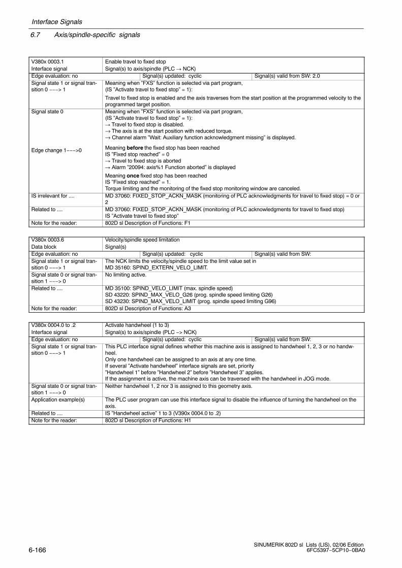
6.7 Axis/spindle-specific signals
Interface Signals
6-166SINUMERIK 802D sl Lists (LIS), 02/06 Edition
6FC5397−5CP10−0BA0
V380x 0003.1 Enable travel to fixed stopInterface signal Signal(s) to axis/spindle (PLC � NCK)Edge evaluation: no Signal(s) updated: cyclic Signal(s) valid from SW: 2.0Signal state 1 or signal tran-sition 0 −−−> 1
Meaning when ”FXS” function is selected via part program,(IS ”Activate travel to fixed stop” = 1):
Travel to fixed stop is enabled and the axis traverses from the start position at the programmed velocity to theprogrammed target position.
Signal state 0
Edge change 1−−−>0
Meaning when ”FXS” function is selected via part program,(IS ”Activate travel to fixed stop” = 1):� Travel to fixed stop is disabled.→ The axis is at the start position with reduced torque.→ Channel alarm ”Wait: Auxiliary function acknowledgment missing” is displayed.
Meaning before the fixed stop has been reachedIS ”Fixed stop reached” = 0� Travel to fixed stop is aborted� Alarm ”20094: axis%1 Function aborted” is displayed
Meaning once fixed stop has been reachedIS ”Fixed stop reached” = 1.Torque limiting and the monitoring of the fixed stop monitoring window are canceled.
IS irrelevant for .... MD 37060: FIXED_STOP_ACKN_MASK (monitoring of PLC acknowledgments for travel to fixed stop) = 0 or2
Related to .... MD 37060: FIXED_STOP_ACKN_MASK (monitoring of PLC acknowledgments for travel to fixed stop)IS ”Activate travel to fixed stop”
Note for the reader: 802D sl Description of Functions: F1
V380x 0003.6 Velocity/spindle speed limitationData block Signal(s)Edge evaluation: no Signal(s) updated: cyclic Signal(s) valid from SW:Signal state 1 or signal tran-sition 0 −−−> 1
The NCK limits the velocity/spindle speed to the limit value set in MD 35160: SPIND_EXTERN_VELO_LIMIT.
Signal state 0 or signal tran-sition 1 −−−> 0
No limiting active.
Related to .... MD 35100: SPIND_VELO_LIMIT (max. spindle speed)SD 43220: SPIND_MAX_VELO_G26 (prog. spindle speed limiting G26)SD 43230: SPIND_MAX_VELO_LIMIT (prog. spindle speed limiting G96)
Note for the reader: 802D sl Description of Functions: A3
V380x 0004.0 to .2 Activate handwheel (1 to 3)Interface signal Signal(s) to axis/spindle (PLC −> NCK)Edge evaluation: no Signal(s) updated: cyclic Signal(s) valid from SW:Signal state 1 or signal tran-sition 0 −−−> 1
This PLC interface signal defines whether this machine axis is assigned to handwheel 1, 2, 3 or no handw-heel.Only one handwheel can be assigned to an axis at any one time.If several ”Activate handwheel” interface signals are set, priority ”Handwheel 1” before ”Handwheel 2” before ”Handwheel 3” applies.If the assignment is active, the machine axis can be traversed with the handwheel in JOG mode.
Signal state 0 or signal tran-sition 1 −−−> 0
Neither handwheel 1, 2 nor 3 is assigned to this geometry axis.
Application example(s) The PLC user program can use this interface signal to disable the influence of turning the handwheel on theaxis.
Related to .... IS ”Handwheel active” 1 to 3 (V390x 0004.0 to .2)Note for the reader: 802D sl Description of Functions: H1

Interface Signals
6.7 Axis/spindle-specific signals
6-167 SINUMERIK 802D sl Lists (LIS), 02/06 Edition6FC5397−5CP10−0BA0
V380x 0004.3 Feed stop/Spindle stop (axis−specific)Interface signal Signal(s) to axis/spindle (PLC → NCK)Edge evaluation: no Signal(s) updated: cyclic Signal(s) valid from SW:Signal state 1 or signaltransition 0 −−−> 1
The signal is active in all modes.
Feed stop:� The signal triggers a feed stop for the axis. Traversing axes are brought to a standstill under
controlled braking (ramp stop). No alarm is output.� The signal triggers a feed stop for all path axes interpolating relative to each other when the ”Feed
stop” is activated for any one of these axes. In this case, all the axes are brought to a stop withadherence to the path contour. When the feed stop signal is canceled, execution of the interruptedpart program is resumed.
� The position control is retained, i.e. the following error is eliminated.� If a travel request is issued for an axis with an active ”Feed stop”, the request is retained. This
pending travel request is executed immediately when ”Feed stop” is canceled.If the axis is interpolating in relation to others, this also applies to these axes.
Spindle stop:� The spindle is brought to a standstill along the acceleration characteristic.� In positioning mode, activation of the ”Spindle stop” signal interrupts the positioning process. The
above response applies with respect to individual axes.Signal state 0 or signaltransition 1 −−−> 0
Feed stop:� The feedrate is enabled for the axis.� If a travel request (”Travel command”) is active when the ”Feed stop” is canceled, this is executed
immediately.Spindle stop:� The speed is enabled for the spindle.� The spindle is accelerated to the previous speed setpoint with the acceleration characteristic or, in
positioning mode, positioning is resumed.Application example(s) Feed stop:
� The traversing motion in the machine axes is not started when ”Feed stop” is active, if, for example,certain operating states that do not permit axis motion (e.g. door not closed) prevail.
Spindle stop:� Change a tool
Special cases, errors, ... ...Note for the reader: 802D sl Description of Functions: V1
V380x 0004.4 Traverse key disableInterface signal Signal(s) to axis/spindle (PLC −> NCK)Edge evaluation: no Signal(s) updated: cyclic Signal(s) valid from SW:Signal state 1 or signal tran-sition 0 −−−> 1
The traverse keys plus and minus have no effect on the machine axes in question. It is thus not possible totraverse the machine axis in JOG with the traverse keys on the machine control panel.If the traverse key disable is activated during a traverse movement, the machine axis is stopped.
Signal state 0 or signal tran-sition 1 −−−> 0
Traverse keys plus and minus are enabled.
Application example(s) It is thus possible, depending on the operating mode, to disable manual traverse of the machine axis in JOGmode with the traverse keys from the PLC user program.
Related to .... IS ”Traverse key plus” and ”Traverse key minus” (V380x 0004.7 and .6)Note for the reader: 802D sl Description of Functions: H1
V380x 0004.5 Rapid traverse overrideInterface signal Signal(s) to axis/spindle (PLC −> NCK)Edge evaluation: no Signal(s) updated: cyclic Signal(s) valid from SW:Signal state 1 or signal tran-sition 0 −−−> 1
If interface signal ”Rapid traverse override” is set together with ”Traverse key plus” and ”Traverse key minus”,the machine axis in question traverses at rapid traverse.The rapid traverse velocity is defined in MD 32010: JOG_VELO_RAPID.Rapid traverse override is active in the following JOG modes:
− Continuous jogging− Incremental jogging
If rapid traverse override is active, the velocity can be modified with the axis-specific feedrate override switch.Signal state 0 or signal tran-sition 1 −−−> 0
The machine axis traverses at the defined JOG velocity (SD 41110: JOG_SET_VELO or SD 41130, or MD 32020: JOG_VELO).
Signal irrelevant for ... ... − Operating modes AUTOMATIC and MDA− Reference point approach (JOG mode)
Related to .... IS ”Traverse key plus” and ”Traverse key minus” (V380x 0004.7 and .6)IS axis-specific ”Feedrate override” (VB380x 0000)
Note for the reader: 802D sl Description of Functions: H1

6.7 Axis/spindle-specific signals
Interface Signals
6-168SINUMERIK 802D sl Lists (LIS), 02/06 Edition
6FC5397−5CP10−0BA0
V380x 0004.7 and .6 Plus and minus traverse keysInterface signal Signal(s) to axis/spindle (PLC −> NCK)Edge evaluation: yes Signal(s) updated: cyclic Signal(s) valid from SW:Signal state 1 or signal tran-sition 0 −−−> 1
The selected axis can be traversed in both directions in JOG mode with the traverse keys plus and minus.Incremental traversing
With signal 1 the axis starts to traverse at the setincrement. If the signal changes to the 0 state before the increment is traversed, the traversing movement is interrupted. Whensignal state 1 occurs again, the traverse motion is restarted.The traversing motionof the axis can be stopped and restarted multiple times as described aboveuntil the increment has been fully traversed.
Continuous traversingIf no INC measure is selected but ”continuous” is, the axis travels for as long as the traverse key is actuated.
If both traverse signals (plus and minus) are set at the same time there is no movement or a current move-ment is aborted.The effect of the traverse keys can be disabled for every axis individually with the PLC interface signal”Traverse key disable”.
Signal state 0 or signal tran-sition 1 −−−> 0
No traverse
Signal irrelevant for ... ... Operating modes AUTOMATIC and MDAApplication example(s) The machine axis cannot be traversed in JOG mode if it is already being traversed via the channel-specific
PLC interface (as a geometry axis). Alarm 20062 is signaled.Special cases, ...... Indexing axesRelated to .... IS ”Traverse key plus” and ” ... minus” for geometry axis 1 (V3200 1000.7 and .6)
for geometry axis 2 (V3200 1004.7 and .6)for geometry axis 3 (V3200 1008.7 and .6)
IS ”Traverse key disable” (V380x 0004.4 )Note for the reader: 802D sl Description of Functions: H1
V380x 0005.0 to .6 Machine functions INC1, INC10, INC100, INC1000, INC10000, INCvar, continuousInterface signal Signal(s) to axis/spindle (PLC −> NCK)Edge evaluation: no Signal(s) updated: cyclic Signal(s) valid from SW:Signal state 1 or signal tran-sition 0 −−−> 1
This input range is only used if IS ”INC inputs in mode group range active” (V2600 0001.0) is not set. The interface signals ”INC...” define how many increments the machine axis traverses when the traverse keyis pressed or the handwheel is turned one detent position. JOG must be active.With ”INCvar” the value in the general SD 41010: JOG_VAR_INCR_SIZE applies.In ”continuous” mode the associated axis can be traversed with the plus or minus traversing key according tohow the traverse key is pressed.
As soon as the selected machine function becomes active, this is signaled to the PLC interface (IS ”Activemachine function INC1...”).If several machine function signals (INC1, INC... or ”Continuous jogging”) are selected at the interface simul-taneously, no machine function is activated by the control.Note: The input IS ”INC...” or ”continuous” for changing an active machine function must be active for at least onePLC cycle. A static application is not required.
Signal state 0 or signal tran-sition 1 −−−> 0
The machine function in question is not selected. No change to the active machine function is requested.If an axis is currently traversing an increment, this movement is also aborted if this machine function is dese-lected or changed over.
Related to .... IS ”Active machine function INC1, ...” (V390x 0005.0 ... .6)IS ”INC inputs in the mode group area active” (V2600 0001.0)
Note for the reader: 802D sl Description of Functions: H1

Interface Signals
6.7 Axis/spindle-specific signals
6-169 SINUMERIK 802D sl Lists (LIS), 02/06 Edition6FC5397−5CP10−0BA0
V380x 1000.1 and .0 Hardware limit switches plus and minusData block Signal(s) to axis/spindle (PLC −−−> NCK)Edge evaluation: no Signal(s) updated: cyclic Signal(s) valid from SW:Signal state 1 or signal tran-sition 0 −−−> 1
A switch can be mounted at each end of the travel range of a machine axis which will cause a signal ”Hard-ware limit switch plus or minus” to be signaled to the NC via the PLC if it is approached. If the signal is recognized as set, alarm 021614 ”Hardware limit switch + or −” is output and the axis is decele-rated immediately. The braking mode is defined in MD 36600: BRAKE_MODE_CHOICE (deceleration behavior on hardware limit switch).
Signal state 0 or signal tran-sition 1 −−−> 0
Normal condition, hardware limit switch not triggered.
Related to .... MD 36600: BRAKE_MODE_CHOICE (deceleration behavior on hardware limit switch)Note for the reader: 802D sl Description of Functions: A3
V380x1000.3 or .2 2nd software limit switch plus or minusData block Signal(s) to axis/spindle (PLC −−−> NCK)Edge evaluation: no Signal(s) updated: cyclic Signal(s) valid from SW:Signal state 1 or signal tran-sition 0 −−−> 1
2nd software limit switch for the plus or minus direction is active.1st software limit switch for the plus or minus direction is not active.The 2nd software limit switches (plus and minus) can be activated in addition to the 1st software limit swit-ches (plus and minus) via this interface signal.The position is defined by MD 36130: POS_LIMIT_PLUS2, MD 36120: POS_LIMIT_MINUS2 (2nd software limit switch plus, 2nd software limit switch minus).
Signal state 0 or signal tran-sition 1 −−−> 0
1st software limit switch for the plus or minus direction is active.2nd software limit switch for the plus or minus direction is not active.
Related to .... MD 36110: POS_LIMIT_PLUS, MD 36130: POS_LIMIT_PLUS2, MD 36100: POS_LIMIT_MINUS, MD 36120: POS_LIMIT_MINUS2, (software limit switch plus, software limitswitch minus)
Note for the reader: 802D sl Description of Functions: A3
V380x1000.7 Reference point approach delayInterface signal Signal(s) to axis/spindle (PLC −> NCK)Edge evaluation: no Signal(s) updated: cyclic Signal(s) valid from SW:Signal state 1 or signal tran-sition 0 −−−> 1
The machine axis is positioned at the reference cam.
Signal state 0 or signal tran-sition 1 −−−> 0
The machine axis is positioned in front of the reference cam. A reference cam of appropriate length (to theend of the traversing range) has been used to prevent the machine axis from being positioned behind thereferencing cam.
Related to ....Note for the reader: 802D sl Description of Functions: R1

6.7 Axis/spindle-specific signals
Interface Signals
6-170SINUMERIK 802D sl Lists (LIS), 02/06 Edition
6FC5397−5CP10−0BA0
V380x 2000.0 to .2 Actual gear stage A to CInterface signal Signal(s) to axis/spindle (PLC −> NCK)Edge evaluation: yes Signal(s) updated: cyclic Signal(s) valid from SW:Signal state 1(level−operated)
When the new gear is engaged, the IS ”Actual gear stage A to C” and ”Gear changed” are enabled by thePLC user. This informs the NCK that the correct gear stage has been successfully engaged. The gearchange is complete (spindle oscillation mode is deselected), the spindle accelerates in the new gear stage tothe last programmed spindle speed and the next block in the part program can be executed.The actual gear stage is specified in coded format (ABC values).A parameter set is used for each of the 5 gear stages and is assigned as follows:
Parameter VDI Data in data set contentsset no. code
CBA0 − Data for axis mode Servo gain factor
Monitoring functions1 000 Data for 1st gear stage M40 speed
001 Min/max speedAcceleration
2 010 Data for 2nd gear stage etc.3 011 Data for 3rd gear stage4 100 Data for 4th gear stage5 101 Data for 5th gear stage
110111
Special cases, errors, ... ... If the PLC user reports back to the NCK with a different actual gear stage than issued by the NCK as the setgear stage, the gear change is still treated as having been successfully completed and the actual gear stageA to C is activated.
Related to .... IS ”Set gear stage A” to ”...C” (V390x 2000.0 to .2)IS ”Change gear” (V390x 2000.3)IS ”Gear changed” (V380x 2000.3)IS ”Oscillation speed” (V380x 2002.5)Parameter sets (MD) for gear stages.
Note for the reader: 802D sl Description of Functions: S1
V380x 2000.3 Gear changedInterface signal Signal(s) to axis/spindle (PLC −> NCK)Edge evaluation: yes Signal(s) updated: cyclic Signal(s) valid from SW:Signal state 1 or signaltransition 0 −−−> 1
When the new gear is engaged, the IS ”Actual gear stage A to C” and ”Gear changed” are enabled by thePLC user. This informs the NCK that the correct gear stage has been successfully engaged. The gear stagechange is complete (spindle oscillation mode is deselected), the spindle accelerates in the new gear stage tothe last programmed spindle speed and the next block in the part program can be executed. The IS ”Changegear” is reset by the NCK, which causes the PLC user to reset the IS ”Gear changed”.
Signal state 0 or signaltransition 1 −−−> 0
No effect
Signal irrelevant for ... ... All spindle modes except oscillation modeSpecial cases, errors, ... ... If the PLC user reports back to the NCK with a different actual gear stage than issued by the NCK as the set
gear stage, the gear change is still treated as having been successfully completed and the actual gear stageA to C is activated.
Related to .... IS ”Actual gear stage A” to C” (V380x 2000.0 to .2)IS ”Set gear stage A” to ”...C” (V390x 2000.0 to .2)IS ”Change gear” (V390x 2000.3)IS ”Oscillation speed” (V380x 2002.5)
Note for the reader: 802D sl Description of Functions: S1

Interface Signals
6.7 Axis/spindle-specific signals
6-171 SINUMERIK 802D sl Lists (LIS), 02/06 Edition6FC5397−5CP10−0BA0
V380x 2001.0 Feedrate override for spindle valid (instead of spindle override)Interface signal Signal(s) from axis/spindle (PLC −> NCK)
Edge evaluation: yes Signal(s) updated: cyclic Signal(s) valid from SW:
Signal state 1 or signaltransition 0 −−−> 1
The ”Feedrate override” value(VB380x 0000) is used for the spindle instead of the ”Spindle override” value.
Signal state 0 or signaltransition 1 −−−> 0
The ”Spindle override” value is used.
Related to .... IS ”Spindle override” (VB380x 2003)IS ”Feedrate override” (V380x 0000)IS ”Override active” (V380x 0001.7)
Note for the reader: 802D sl Description of Functions: V1
V380x 2001.4 Resynchronize spindle during positioning 1Interface signal Signal(s) to axis/spindle (PLC −> NCK)Edge evaluation: yes Signal(s) updated: cyclic Signal(s) valid from SW:Signal state 1 The spindle must be resynchronized during positioning.Signal state 0 or signaltransition 1 −−−> 0
No effect
Signal irrelevant for ... ... All spindle modes except for positioning modeApplication example(s) The spindle has an indirect measuring system and slipping may occur between the motor and the clamp. If
the signal=1 when the positioning process is started, the old reference is deleted and the zero mark searchedfor again before the end position is approached.
Related to .... ”Referenced/synchronizing 1” interface signal (V390x 0000.4)Note for the reader: 802D sl Description of Functions: S1
V380x 2001.6 Invert M3/M4Interface signal Signal(s) to axis/spindle (PLC −> NCK)Edge evaluation: yes Signal(s) updated: cyclic Signal(s) valid from SW:Signal state 1 or signaltransition 0 −−−> 1
The direction of rotation of the spindle motor changes with the following functions:� M3� M4� M5� SPOS from movement; not active for SPOS from standstill.
Application example(s) The machine has a selector switch for a vertical and horizontal spindle. The mechanical design incorporatesone gear wheel more on the horizontal spindle than on the vertical spindle. The direction of rotation musttherefore be changed on the vertical spindle if the spindle is always to rotate clockwise with M3.
Note for the reader: 802D sl Description of Functions: S1
V380x 2002.4 Oscillation via PLCInterface signal Signal(s) to axis/spindle (PLC −> NCK)Edge evaluation: yes Signal(s) updated: cyclic Signal(s) valid from SW:Signal state 1 or signaltransition 0 −−−> 1
If the IS ”Oscillation via PLC” is enabled, the IS ”Oscillation speed” effects output of a speed only in conjunc-tion with the IS ”Direction of rotation setpoint counter-clockwise and clockwise”. The oscillation, i.e. the conti-nuous change of the direction of rotation, is performed by the PLC user with the IS ”Direction of rotation set-point counter-clockwise and clockwise” (oscillation via PLC).
Signal state 0 or signaltransition 1 −−−> 0
If the IS ”Oscillation via PLC” is not enabled, the IS ”Oscillation speed” triggers automatic oscillation on theNCK. The two times for the directions of rotation are entered in MD 35440: SPIND_OSCILL_TIME_CW(oscillation time for M3 direction) SPIND_OSCILL_TIME_CW (oscillation time for M3 direction) and MD35450: SPIND_OSCILL_TIME_CCW (oscillation time for M4 direction).
Application example(s) If the new gear stage cannot be engaged in spite of several attempts by the NCK, the system can be swit-ched to oscillation via PLC. Both of the times can then be altered by the PLC user. This assures a reliablechange of the gear stage, even with unfavorable gear wheel positions.
Related to .... MD 35440: SPIND_OSCILL_TIME_CW (oscillation time for direction M3) MD 35450: SPIND_OSCILL_TIME_CCW (oscillation time for M4 direction)IS ”Oscillation speed” (V380x 2002.5)IS ”Set direction of rotation counterclockwise” (V380x 2002.7)IS ”Set direction of rotation clockwise” (V380x 2002.6)
Note for the reader: 802D sl Description of Functions: S1

6.7 Axis/spindle-specific signals
Interface Signals
6-172SINUMERIK 802D sl Lists (LIS), 02/06 Edition
6FC5397−5CP10−0BA0
V380x 2002.5 Oscillation speedInterface signal Signal(s) to axis/spindle (PLC −> NCK)Edge evaluation: no Signal(s) updated: cyclic Signal(s) valid from SW: 1.1Signal state 1 or signaltransition 0 −−−> 1
If the gear stage must be changed (IS ”Change gear” (V390x 2000.3) is enabled), the spindle changes tooscillation mode.The spindle decelerates to a standstill with different acceleration levels, according to the point when the IS”Oscillation speed” (V380x 2002.5) was enabled:
1. The IS ”Oscillation speed” is enabled before the IS ”Change gear” is enabled by the NCK. The spindle isbrought to a standstill with the acceleration during oscillation (MD: SPIND_OSCILL_ACCEL). Once the spindle is stationary, oscillationis immediately initiated.
2. The IS ”Oscillation speed” is enabled after the IS ”Change gear” is enabled by the NCK and when thespindle is stationary. The position controller is disabled. The spindle decelerates with the decelerationrate in speed controlled mode. After the IS ”Oscillation speed”is set, the spindle starts to oscillate with theoscillation acceleration (MD:SPIND_OSCILL_ACCEL).
If the IS ”Oscillation via PLC” (V380x 2002.4) is not enabled, the IS ”Oscillation speed” triggers automaticoscillation on the NCK. The two times for the directions of rotation are entered in MD: inSPIND_OSCILL_TIME_CW (oscillation time for M3 direction) and SPIND_OSCILL_TIME_CCW (oscillationtime for M4 direction).If the IS ”Oscillation via PLC” is enabled, the IS ”Oscillation speed” effects output of a speed only in conjunc-tion with the IS ”Direction of rotation setpoint counter-clockwise and clockwise”. The oscillation, i.e. the conti-nuous change of the direction of rotation, is performed by the PLC user with the IS ”Direction of rotation set-point counter-clockwise and clockwise” (oscillation via PLC).
Signal state 0 or signaltransition 1 −−−> 0
The spindle does not oscillate.
Signal irrelevant for ... ... All spindle modes except oscillation modeApplication example(s) The oscillation speed is used to facilitate the engagement of a new gear stage.Related to .... IS ”Oscillation via the PLC” (V380x 2002.4)
IS ”Set direction of rotation counterclockwise” (V380x 2002.7)IS ”Set direction of rotation clockwise” (V380x 2002.6)
Note for the reader: 802D sl Description of Functions: S1
V380x 2002.7 / .6 Setpoint direction of rotation, counter-clockwise/setpoint direction of rotation, clockwiseInterface signal Signal(s) to axis/spindle (PLC −> NCK)Edge evaluation: yes Signal(s) updated: cyclic Signal(s) valid from SW: 1.1Signal state 1 or signaltransition 0 −−−> 1
When the IS ”Oscillation via PLC” is enabled, the two IS ”Direction of rotation setpoint counterclockwise” and”Direction of rotation setpoint clockwise” can be used to set the direction of rotation for the oscillation speed.The times for the oscillation movement of the spindle motor are defined by enabling the IS ”Direction of rota-tion setpoint counterclockwise and clockwise” for a corresponding length of time.
Signal irrelevant for ... ... All spindle modes except oscillation modeApplication example(s) See IS ”Oscillation via PLC”Special cases, errors, ... ... � If both of the IS are enabled simultaneously, no oscillation speed is output.
� If no IS are set, then an oscillation speed is not output.Related to .... IS ”Oscillation via the PLC” (V380x 2002.4)
IS ”Oscillation speed” (V380x 2002.5)Note for the reader: 802D sl Description of Functions: S1

Interface Signals
6.7 Axis/spindle-specific signals
6-173 SINUMERIK 802D sl Lists (LIS), 02/06 Edition6FC5397−5CP10−0BA0
VB380x 2003 Spindle overrideInterface signal Signal(s) to spindle (PLC → NCK)Edge evaluation: no Signal(s) updated: cyclic Signal(s) valid from SW:Signal state 1 or signaltransition 0 −−−> 1
The spindle override is defined via the PLC in gray coding.The override value determines the percentage of the programmed speed setpoint that is issued to thespindle.
Table 6-4 Gray coding for spindle override
Switchposition
Code Spindle override factor
12345678910111213141516171819202122232425262728293031
00001000110001000110001110010100100011000110101111011100101001011010010100011000110011101111010111101111111101111001010010101101111011010010100111000110000
0.50.550.600.650.700.750.800.850.900.951.001.051.101.151.201.201.201.201.201.201.201.201.201.201.201.201.201.201.201.201.20
Related to .... IS ”Override active” (V380x 0001.7) IS ”Feedrate override for spindle valid” (V380x 2001.0)
Note for the reader: 802D sl Description of Functions: V1

6.7 Axis/spindle-specific signals
Interface Signals
6-174SINUMERIK 802D sl Lists (LIS), 02/06 Edition
6FC5397−5CP10−0BA0
6.7.3 Signals from axis/spindle
V390x 0000.0 Spindle/no axisInterface signal Signal(s) from axis/spindle (NCK −> PLC)Edge evaluation: yes Signal(s) updated: cyclic Signal(s) valid from SW:Signal state 1 or signaltransition 0 −−−> 1
The machine axis is operated as a spindle in the following spindle modes:
� Control mode� Oscillation mode� Positioning mode� Thread drilling (tapping) without compensating chuck (rigid tapping)The IS to axis (V380x 1000 to V380x 1003) and from axis (V390x 1000 to V390x 1003) are invalid.The IS to spindle (V380x 2000 to V380x 2003) and from spindle (V380x 2000 to V380x 2003) are valid.
Signal state 0 or signaltransition 1 −−−> 0
The machine axis is operated as an axisThe IS to axis (V380x 1000 to V380x 1003) and from axis (V390x 1000 to V390x 1003) are valid.The IS to spindle (V380x 2000 to V380x 2003) and from spindle (V380x 2000 to V380x 2003) are invalid.
Application examples If a spindle is sometimes also used as a rotary axis on a machine tool (turning machine with spindle/C axis ormilling machine with spindle/rotary axis for rigid tapping), the ”Spindle/no axis” signal can be used to deter-mine whether the machine axis is in axis mode or spindle mode.
Note for the reader: 802D sl Description of Functions: S1
V390x 0000.2 Encoder limit frequency exceeded 1Data block Signal(s) from axis/spindle (NCK −−−> PLC)Edge evaluation: no Signal(s) updated: cyclic Signal(s) valid from SW:Signal state 1 or signal tran-sition 0 −−−> 1
The axis velocity defined in MD 36300: ENC_FREQ_LIMIT (encoder limit frequency) has been exceeded.The reference point for the position measuring system concernedhas been lost (IS: Referenced/synchronized is in signal state 0). Proper position closed loop control is nolonger possible. The spindles continue to run with speed control.The axes are brought to a standstill with rapid stop (with open position control loop) along a speed setpointramp.
Signal state 0 or signal tran-sition 1 −−−> 0
The axis velocity defined in MD 36300: ENC_FREQ_LIMIT is no longer exceeded. For the edge change 1 −−>, the encoder frequency must have dropped below the setting in MD 36302:ENC_FREQ_LIMIT_LOW (% value of MD 36300: ENC_FREQ_LIMIT).
Note for the reader: 802D sl Description of Functions: A3
V390x 0000.4 Referenced/synchronizing 1Interface signal Signal(s) from axis/spindle (NCK −> PLC)Edge evaluation: Signal(s) updated: Signal(s) valid from SW:Signal state 1 or signal tran-sition 0 −−−> 1
Axes:When, during a reference point approach, the machine axis has reached thereference point (incremental measurement systems) or target point (linear measuring system with distance-coded reference marks), the machine axis is deemed to have been referenced and the ”referenced/synchronizing 1” interface signal (depending on which position measurement system is active during referencing) is enabled.
Spindles:A spindle is synchronized (zero mark crossed or BERO responded) after Power On after one
spindle revolution at the latest.Signal state 0 or signal tran-sition 1 −−−> 0
The machine axis/spindle with position measurement system 1 is not referenced/synchronizing.
Related to .... ”Position measuring system 1” interface signal (V380x 0000.5)Note for the reader: 802D sl Description of Functions: R1, S1

Interface Signals
6.7 Axis/spindle-specific signals
6-175 SINUMERIK 802D sl Lists (LIS), 02/06 Edition6FC5397−5CP10−0BA0
V390x 0000.6 Position reached with exact stop coarseData block Signal(s) from axis/spindle (NCK −> PLC)Edge evaluation: no Signal(s) updated: cyclic Signal(s) valid from SW:Signal state 1 or signal tran-sition 0 −−−> 1
The axis is in the appropriate exact stop and no interpolator is active for the axis and− The control system is in the Reset mode (Reset key or end of program).− The axis was last programmed as a positioning spindle.− The path movement was stopped with NC Stop.− The spindle is in position-controlled mode and is stationary.− The axis is switched from speed-controlled to position-controlled mode with IS ”Position measuring sy-
stem”.Signal state 0 or signal tran-sition 1 −−−> 0
The axis is not in the appropriate exact stop or the interpolator is active for the axis or− The path movement was stopped with NC Stop.− The spindle is in the speed−controlled mode.− ”Parking mode” is active for the axis.− The axis is switched from the position-controlled to the speed−controlled mode with using the IS ”Position
measuring system”.Signal irrelevant for ... ...Related to .... MD 36000: STOP_LIMIT_COARSE (exact stop coarse)Note for the reader: 802D sl Description of Functions: B1
V390x 0000.7 Position reached with exact stop fineData block Signal(s) from axis/spindle (NCK −> PLC)Edge evaluation: no Signal(s) updated: cyclic Signal(s) valid from SW:Signal state 1 or signal tran-sition 0 −−−> 1
See IS ”Position reached with exact stop coarse”
Signal state 0 or signal tran-sition 1 −−−> 0
See IS ”Position reached with exact stop coarse”
Signal irrelevant for ... ...Related to .... MD 36010: STOP_LIMIT_FINE (exact stop fine)Note for the reader: 802D sl Description of Functions: B1
V390x 0002.3 Measurement activeInterface signal Signal(s) from axis/spindle (NCK → PLC)Edge evaluation: no Signal(s) updated: cyclic Signal(s) valid from SW:Signal state 1 or signal tran-sition 0 −−−> 1
The ”Measuring” function is active.
This displays the current measurement status of the axis (measuring block with this axis is running).Signal state 0 or signal tran-sition 1 −−−> 0
The ”Measuring” function is not active.
Note for the reader: 802D sl Description of Functions: M5
V390x 0002.4 Activate travel to fixed end stopInterface signal Signal(s) from axis/spindle (NCK � PLC)Edge evaluation: no Signal(s) updated: cyclic Signal(s) valid from SW: 2.0Signal state 1 or signal tran-sition 0 −−−> 1
The ”Travel to fixed stop function” is active.
Signal state 0 or signal tran-sition 1 −−−> 0
The ”Travel to fixed stop function” is not active.
Note for the reader: 802D sl Description of Functions: F1
V390x 0002.5 Fixed stop reachedInterface signal Signal(s) from axis/spindle (NCK � PLC)Edge evaluation: no Signal(s) updated: cyclic Signal(s) valid from SW: 2.0Signal state 1 or signal tran-sition 0 −−−> 1
The fixed stop was reached after selection of the ”FXS” function.
Signal state 0 or signal tran-sition 1 −−−> 0
The fixed stop has still not been reached after selection of the ”FXS” function.
Note for the reader: 802D sl Description of Functions: F1

6.7 Axis/spindle-specific signals
Interface Signals
6-176SINUMERIK 802D sl Lists (LIS), 02/06 Edition
6FC5397−5CP10−0BA0
V390x 0004.0 to .2 Handwheel active (1 to 3)Interface signal Signal(s) from axis/spindle (NCK −> PLC)Edge evaluation: no Signal(s) updated: cyclic Signal(s) valid from SW: 1.1Signal state 1 or signal tran-sition 0 −−−> 1
These PLC interface signals provide feedback whether the machine axis is assigned to handwheel 1, 2, 3 orno handwheel.Only one handwheel can be assigned to an axis at any one time.If several ”Activate handwheel” interface signals are set, priority ”Handwheel 1” before ”Handwheel 2” before ”Handwheel 3” applies.If the assignment is active, the machine axis can be traversed with the handwheel in JOG mode.
Signal state 0 or signal tran-sition 1 −−−> 0
Neither handwheel 1, 2 nor 3 is assigned to this geometry axis.
Related to .... IS ”Activate handwheel” (V380x 0004.0 to .2)IS ”Handwheel selected” from HMI (V1900 0003, ff)
Note for the reader: 802D sl Description of Functions: H1
V390x 0004.7 and .6 Plus and minus traverse keysInterface signal Signal(s) from axis/spindle (NCK −> PLC)Edge evaluation: no Signal(s) updated: cyclic Signal(s) valid from SW:Signal state 1 or signal tran-sition 0 −−−> 1
A traverse movement of the axis is to be executed in one or the other direction. Depending on the mode se-lected, the command is triggered in different ways:
− JOG mode: with the plus or minus traverse key
− REF submode: with the traverse key that takes the axis to the reference point
− AUT/MDA mode: the program block containing a coordinate value for the axis in question is execu-ted.
Signal state 0 or signal tran-sition 1 −−−> 0
A travel command in the relevant axis direction has not been given or a traverse movement has been com-pleted.� JOG mode:
− Cancelation of traverse key.− While ending traversing with the handwheel.− REF submode: When the reference point is reached
� AUT/MDA mode:− The program block has been executed (and the next block does not contain
any coordinate values for the axis in question)− Abort with ”RESET”, etc.− IS ”Axis disable” is active
Application example(s) To release clamping of axes with clamping (e.g. on a rotary table).Note: If the clamping is not released until the travel command is given, these
axes cannot be operated under continuous path control!Related to .... IS ”Traverse key plus” and ”Traverse key minus” (V380x 0004.7 and .6)Note for the reader: 802D sl Description of Functions: H1
V390x 0005.0, ..., .6 Active machine function INC1, ..., continuousInterface signal Signal(s) from axis/spindle (NCK −> PLC)Edge evaluation: no Signal(s) updated: cyclic Signal(s) valid from SW: 1.1Signal state 1 or signal tran-sition 0 −−−> 1
The PLC interface receives a signal stating which JOG mode machine function is active for the machineaxes.
Signal state 0 or signal tran-sition 1 −−−> 0
The machine function in question is not active.
Related to .... IS ”Machine function INC1,...,continuous” (V380x 0005.0, ..., .6)Note for the reader: 802D sl Description of Functions: H1

Interface Signals
6.7 Axis/spindle-specific signals
6-177 SINUMERIK 802D sl Lists (LIS), 02/06 Edition6FC5397−5CP10−0BA0
V390x 2000.0 to .2 Set gear stage A to CInterface signal Signal(s) from axis/spindle (NCK −> PLC)Edge evaluation: yes Signal(s) updated: cyclic Signal(s) valid from SW:Signal state 1 or signaltransition 0 −−−> 1
A gear stage can be defined as follows:
� Permanent definition in the part program (M41 to M45)
� Automatic definition by the programmed spindle speed (M40)M41 to M45:
� The gear stage can be permanently defined in the part program with M41 to M45. If the M41 to M45 com-mands select a gear stage which is not the same as the current (actual) gear stage, the IS ”Change gear”and the IS ”Set gear stage A to C” are enabled.
M40:
� M40 in the part program causes the gear stage to be selected automatically by the control. The controlchecks which gear stage is possible for the programmed spindle speed (S function). If a gear stage isidentified that is not equal to the current (actual) gear stage, the ”Change gear” and ”Set gear stage A” to”...C” interface signals are set.
The set gear stage is output in coded format:1st gear stage 0 0 0 (C B A)1st gear stage 0 0 12nd gear stage 0 1 03rd gear stage 0 1 14th gear stage 1 0 05th gear stage 1 0 1Invalid value 1 1 0Invalid value 1 1 1
Signal irrelevant for ... ... Other spindle modes except oscillation modeRelated to .... IS ”Change gear” (V390x 2000.3)
IS ”Actual gear stage A” to ”...C” (V380x 2000.0 to .2)IS ”Gear changed” (V380x 2000.3)
Note for the reader: 802D sl Description of Functions: S1
V390x 2000.3 Change gear stageInterface signal Signal(s) from axis/spindle (NCK −> PLC)Edge evaluation: yes Signal(s) updated: cyclic Signal(s) valid from SW:Signal state 1 or signaltransition 0 −−−> 1
A gear stage can be defined as follows:� Permanent definition in the part program (M41 to M45)� Automatic definition by the programmed spindle speed (M40)M41 to M45:� The gear stage can be permanently defined in the part program with M41 to M45. If the M41 to M45 com-
mands select a gear stage which is not the same as the current (actual) gear stage, the IS ”Change gear”and the IS ”Set gear stage A to C” are enabled.
M40:� M40 in the part program causes the gear stage to be selected automatically by the control. The control
checks which gear stage is possible for the programmed spindle speed (S function). If a gear stage isidentified that is not equal to the current (actual) gear stage, the ”Change gear” and ”Set gear stage A” to”...C” interface signals are set.
� While the signal = 1, the text ”Wait for gear stage change” is displayedin the channel operating message”.
Special cases, errors, ... ... The IS ”Change gear” is only enabled when a new gear stage is selected that is not equal to the currentactual gear stage.
Related to .... IS ”Set gear stage A” to C”(V390x 2000.0 to .2)IS ”Actual gear stage A” to ”...C” (V380x 2000.0 to .2)IS ”Gear changed” (V380x 2000.3)
Note for the reader: 802D sl Description of Functions: S1

6.7 Axis/spindle-specific signals
Interface Signals
6-178SINUMERIK 802D sl Lists (LIS), 02/06 Edition
6FC5397−5CP10−0BA0
V390x 2001.0 Speed limit exceededInterface signal Signal(s) from axis/spindle (NCK −> PLC)Edge evaluation: yes Signal(s) updated: cyclic Signal(s) valid from SW:Signal state 1 or signaltransition 0 −−−> 1
If the actual speed exceeds the maximum spindle speed MD 35100: SPIND_VELO_ LIMIT by more than thespindle speed tolerance MD 35150: SPIND_DES_VELO_TOL the IS ”Speed limit exceeded” is enabled andalarm 22050 ”Maximum speed reached” is output. All axes and spindles of the channel are brought to astandstill.
Related to .... MD 35150: SPIND_DES_VELO_TOL (spindle speed tolerance)MD 35100: SPIND_VELO_LIMIT (maximum spindle speed) Alarm 22050 ”Maximum speed reached”
Note for the reader: 802D sl Description of Functions: S1
V390x 2001.1 Setpoint speed limited (programmed speed too high)Interface signal Signal(s) from axis/spindle (NCK −> PLC)Edge evaluation: yes Signal(s) updated: cyclic Signal(s) valid from SW:Signal state 1 or signaltransition 0 −−−> 1
If a spindle speed (rev/min) or a constant cutting speed (m/min or ft/min) is programmed, the value is excee-ded one of the following limits:� Max. speed of specified gear stage� Maximum spindle speed� Speed limited by the PLC interface signal� Progr. Spindle speed limiting G26� Progr. Spindle speed limiting for G96
The spindle speed is limited to the maximum limit.Signal state 0 or signaltransition 1 −−−> 0
If a spindle speed (1/min) or a constant cutting speed (m/min) or ft/min) is programmed, none of the limit va-lues have been exceeded.
Application example(s) The IS ”Setpoint speed limited” can be used to detect that the programmed speed cannot be achieved. ThePLC user can recognize this condition as not permissible and block path feed, or he can block the path feedor the entire channel. IS ”Spindle in set range” is processed.
Note for the reader: 802D sl Description of Functions: S1
V390x 2001.2 Setpoint speed increased (programmed speed too low)Interface signal Signal(s) from axis/spindle (NCK −> PLC)Edge evaluation: yes Signal(s) updated: cyclic Signal(s) valid from SW:Signal state 1 or signaltransition 0 −−−> 1
If a spindle speed (rev/min) or a constant cutting speed (m/min or ft/min) is programmed, the value is belowone of the following limits:� Minimum speed of the specified gear stage� Min. spindle speed� Speed limited by the PLC� Progr. Spindle speed limiting G25� Progr. spindle speed limit for G96
The spindle speed is limited to the minimum limit.Signal state 0 or signaltransition 1 −−−> 0
If a spindle speed (1/min) or a constant cutting speed (m/min or ft/min) is programmed, the value has notfallen below any of the limits.
Application example(s) The IS ”Setpoint speed increased” can be used to detect that the programmed speed cannot be achieved.The PLC user can recognize this condition as not permissible and block path feed, or he can block the pathfeed or the entire channel. IS ”Spindle in set range” is processed.
Note for the reader: 802D sl Description of Functions: S1

Interface Signals
6.7 Axis/spindle-specific signals
6-179 SINUMERIK 802D sl Lists (LIS), 02/06 Edition6FC5397−5CP10−0BA0
V390x 2001.5 Spindle in setpoint rangeInterface signal Signal(s) from axis/spindle (NCK −> PLC)Edge evaluation: yes Signal(s) updated: cyclic Signal(s) valid from SW:Signal state 1 or signaltransition 0 −−−> 1
The IS ”Spindle in setpoint range” reports whether the programmed, and possibly limited spindle speed hasbeen reached.In the spindle ”control mode”, the speed setpoint (programmed speed + spindle override including limits) iscompared with the actual speed. If the actual speed deviates from the set speed by less than the spindlespeed tolerance in MD 35150: SPIND_DES_VELO_TOL, the IS ”Spindle in setpoint range” is enabled.
Signal state 0 or signaltransition 1 −−−> 0
The IS ”Spindle in setpoint range” reports whether the spindle is still in the acceleration or braking phase.In the spindle control mode, the speed setpoint (programmed speed * spindle override) is compared with theactual value. If the actual speed deviates from the set speed by more than the spindle speed tolerance inSPIND_DES_VELO_TOL, the IS ”Spindle in setpoint range” is reset.
Signal irrelevant for ... ... all spindle modes except for speed mode (control mode).Application example(s) The path feed must generally be disabled when the spindle is in the acceleration phase (programmed speed
setpoint not yet reached).This can be performed as follows:
� The IS ”Spindle in setpoint range” is evaluated and the IS ”Feed disable”(V3200 0006.0) is enabled.
� MD 35500: SPIND_ON_SPEED_AT_IPO_START (feed enable with spindle in setpoint range) is enabledand the NCK then internally evaluates whether the spindle is in the setpoint range. The path feed is onlyenabled if the spindle is within the setpoint range. The positioning axes are never stopped by this func-tion.
Related to .... MD 35500: SPIND_DES_VELO_TOL (spindle speed tolerance)Note for the reader: 802D sl Description of Functions: S1
V390x 2001.7 Actual direction of rotation clockwiseInterface signal Signal(s) from axis/spindle (NCK −> PLC)Edge evaluation: yes Signal(s) updated: cyclic Signal(s) valid from SW:Signal state 1 or signaltransition 0 −−−> 1
When the spindle is rotating, ”Actual direction of rotation clockwise” = 1 signals that the direction of rotation isCLOCKWISE. The actual direction of rotation is derived from the spindle position measurement encoder.
Signal state 0 or signaltransition 1 −−−> 0
When the spindle is rotating, ”Actual direction of rotation clockwise” = 0 signals that the direction of rotation isCOUNTERCLOCKWISE.
Signal irrelevant for ... ... � Spindle stationary, IS ”Axis/spindle stationary” = 1 (at standstill it is not possible to evaluate a direction ofrotation)
� Spindles without a position measuring encoderRelated to .... IS ”Spindle stationary” (V390x 0001.4)Note for the reader: 802D sl Description of Functions: S1
V390x 2002.0 Constant cutting rate activeInterface signal Signal(s) from axis/spindle (NCK −> PLC)Edge evaluation: yes Signal(s) updated: cyclic Signal(s) valid from SW:Signal state 1 or signaltransition 0 −−−> 1
For programming G96 S... the constant cutting rate function is carried out. The S word is now the cuttingvalue.
Related to ....Note for the reader: 802D sl Description of Functions: S1

6.7 Axis/spindle-specific signals
Interface Signals
6-180SINUMERIK 802D sl Lists (LIS), 02/06 Edition
6FC5397−5CP10−0BA0
V390x 2002.3 Rigid tapping active (no compensation)Interface signal Signal(s) from axis/spindle (NCK −> PLC)Edge evaluation: yes Signal(s) updated: cyclic Signal(s) valid from SW:Signal state 1 or signaltransition 0 −−−> 1
The spindle is running in the rigid tapping function [no compensating chuck] (thread interpolation G331/G332).The spindle speed is also programmed with S.... in rev/min for rigid tapping, however the direction of rotationis stored in the sign for the pitch.There is no reaction or updating of all spindle-specific interface signals such as:IS ”Spindle reset”IS ”Synchronize spindle”IS ”Invert M3/M4”IS ”Spindle in setpoint range”IS ”Programmable speed too high”
Application example(s) Certain functions should not be used during rigid tapping (no compensating chuck), such as:
� Reset IS ”Controller enable” (V380x 0002.1)
� IS ”Set feed stop” (V380x 0004.3)
� Reset
� When activating the EMERGENCY STOP during rigid tapping, it should be remembered that the tool andworkpiece are locked together.
Related to ....Note for the reader: 802D sl Description of Functions: S1
V390x 2002.5 Active spindle positioning modeInterface signal Signal(s) from axis/spindle (NCK −> PLC)Edge evaluation: yes Signal(s) updated: cyclic Signal(s) valid from SW:Signal state 1 or signaltransition 0 −−−> 1
When programming SPOS=..... the spindle is in positioning mode.
Related to .... IS ”Active spindle mode control mode” (V390x 2002.7)IS ”Active spindle mode oscillation mode” (V390x 2002.6)
Note for the reader: 802D sl Description of Functions: S1
V390x 2002.6 Active spindle mode oscillation modeInterface signal Signal(s) from axis/spindle (NCK −> PLC)Edge evaluation: yes Signal(s) updated: cyclic Signal(s) valid from SW:Signal state 1 or signaltransition 0 −−−> 1
The spindle is in oscillation mode if a new gear stage was defined using the automatic gear stage selection(M40) or M41 to M45 (IS ”Change gear” is enabled). The IS ”Change gear” is only enabled when a new gearstage is selected that is not equal to the current actual gear stage.
Related to .... IS ”Active spindle mode control mode” (V390x 2002.7)IS ”Active spindle mode positioning mode” (V390x 2002.5)IS ”Change gear” (V390x 2000.3)
Note for the reader: 802D sl Description of Functions: S1
V390x 2002.7 Active spindle control modeInterface signal Signal(s) from axis/spindle (NCK −> PLC)Edge evaluation: yes Signal(s) updated: cyclic Signal(s) valid from SW:Signal state 1 or signaltransition 0 −−−> 1
The spindle is in control mode with the following functions:Spindle direction of rotation input M3/M4 or spindle stop M5
Related to .... IS ”Active spindle mode oscillation mode” (V390x 2002.6)IS ”Active spindle mode positioning mode” (V390x 2002.5)
Note for the reader: 802D sl Description of Functions: S1
V390x5004.2 Reciprocation reversal activeInterface signal Signal(s) from axis/spindleEdge evaluation: no Signal(s) updated: cyclically Signal(s) valid from SW release: 7.2Signal status 1 or The braking phase after reciprocation reversal from external (DB31, ...DBX28.0) is active.signal transition 0 −−−> 1Signal status 0 or No braking after reciprocation reversal from external is active.signal transition 1 −−−> 0

Interface Signals
6.7 Axis/spindle-specific signals
6-181 SINUMERIK 802D sl Lists (LIS), 02/06 Edition6FC5397−5CP10−0BA0
V390x5004.3 Reciprocation cannot be started.Interface signal Signal(s) from axis/spindleEdge evaluation: no Signal(s) updated: cyclically Signal(s) valid from SW release: 2.1Signal status 1 or The reciprocating axis cannot be started; faulty programming. This state cansignal transition 0 −−−> 1 also occur if the traversing motion has already been performed.Signal status 0 or The reciprocating motion can be started.signal transition 1 −−−> 0
V390x5004.4 Error during the reciprocating motionInterface signal Signal(s)Edge evaluation: Signal(s) updated: Signal(s) valid from SW release: 2.1Signal status 1 or The reciprocating motion was canceled.signal transition 0 −−−> 1Signal status 0 or The reciprocating motion is performed without errors.signal transition 1 −−−> 0
V390x5004.5 Sparking−out activeInterface signal Signal(s) from axis/spindleEdge evaluation: no Signal(s) updated: cyclically Signal(s) valid from SW release: 2.1Signal status 1 or The axis performs sparking−out strokes.signal transition 0 −−−> 1Signal status 0 or The axis is currently not performing any sparking−out strokes.signal transition 1 −−−> 0Related to .... DBX100.7
V390x5004.6 Reciprocating motion activeInterface signal Signal(s) from axis/spindleEdge evaluation: no Signal(s) updated: cyclically Signal(s) valid from SW release: 2.1Signal status 1 or The axis performs a reciprocating motion between 2 reversal points.signal transition 0 −−−> 1Signal status 0 or The axis is currently not reciprocating.signal transition 1 −−−> 0Signal not relevant with ...... DBX100.7 = 0Related to .... DBX100.7
V390x5004.7 Reciprocation activeInterface signal Signal(s) from axis/spindleEdge evaluation: no Signal(s) updated: cyclically Signal(s) valid from SW release: 2.1Signal status 1 or The axis is currently traversed as a reciprocating axis.signal transition 0 −−−> 1Signal status 0 or The axis is a positioning axis.signal transition 1 −−−> 0Related to .... DBX100.5, DBX100.6
V390x5008.0 to .5 Active infeed axesInterface signal Signal(s) from axis/spindleEdge evaluation: no Signal(s) updated: cyclically Signal(s) valid from SW release: 2.1Signal status 1 or The axis that issues the signal is currently the reciprocating axis and reportssignal transition 0 −−−> 1 its active infeed axes (104.0 axis 1 is infeed axis, 104.1 axis 2 is infeed axis,
etc.) in this field.Signal status 0 or The appropriate axis is not an infeed axis.signal transition 1 −−−> 0Related to .... DBX100.7

6.8 Tool management functions from NC channel
Interface Signals
6-182SINUMERIK 802D sl Lists (LIS), 02/06 Edition
6FC5397−5CP10−0BA0
6.8 Tool management functions from NC channel
V5300 0000.0 Tool prewarning limit reachedInterface signal Signal(s) from channel (NCK −−−> PLC)Edge evaluation: yes Signal(s) updated: Job controlled by NCK Signal(s) valid from SW:Signal state 1/ value The prewarning limit for a tool to be monitored was reached.
The T number is provided in VD5300 1000.Signal state 0 No prewarning limit reachedNote for the reader: 802D sl Description of Functions: W1
V5300 0000.1 Tool limit value reachedInterface signal Signal(s) from channel (NCK −−−> PLC)Edge evaluation: yes Signal(s) updated: Job controlled by NCK Signal(s) valid from SW:Signal state 1/ value The limit for a tool to be monitored was reached.
The T number is provided in VD5300 1004.Signal state 0 Limit value reachedNote for the reader: 802D sl Description of Functions: W1
VD5300 1000 T number for tool prewarning limitInterface signal Signal(s) from channel (NCK −−−> PLC)Edge evaluation: yes Signal(s) updated: Job controlled by NCK Signal(s) valid from SW:Signal state 1/ value The T number for which the tool prewarning limit is set is provided.Signal state 0 No tool number reportedNote for the reader: 802D sl Description of Functions: W1
VD5300 1004 T number for tool limit valueInterface signal Signal(s) from channel (NCK −−−> PLC)Edge evaluation: yes Signal(s) updated: Job controlled by NCK Signal(s) valid from SW:Signal state 1/ value The T number for which the tool limit value is set is provided.Signal state 0 No tool number reportedNote for the reader: 802D sl Description of Functions: W1

7-183 SINUMERIK 802D sl Lists (LIS), 02/06 Edition6FC5397−5CP10−0BA0
PLC User Interface
7.1 Address ranges
Operand identifiers Description Area
V Data V0.0 to V79999999.7 (see below)
T Timers T0 to T39
C Counters C0 to C31
I Figure: digital inputs I0.0 to I17.7
Q Figure: digital outputs Q0.0 to Q11.7
M Flag M0.0 to M383.7
SM Special flag SM0.0 to SM 0.6 (see below)
O ACCU (logic) AC0, AC1 (UDword)
O ACCU (arithmetic) AC2, AC3 (Dword)
Structure of V-range addresses:
Type identifier
(DB no.)
Range No.
(channel and axisNo.)
Subarea Offset addressing
10
(10−79)
00
(00−99)
0
(0−9)
000
(000−999)symbolic (8-digit)
Special flag − SM bit definition (read-only):
SM bits Description
SM0.0 Flag with defined ONE signal
SM0.1 Initial setting: first PLC cycle ’1’, following cycles ’0’
SM0.2 Buffered data lost − only valid in first PLC cycle (’0’ data ok, ’1’ data lost)
SM0.3 Power On: first PLC cycle ’1’, following cycles ’0’
SM 0.4 60 s cycle (alternating ’0’ for 30 s, then ’1’ for 30 s)
SM 0.5 1 s cycle (alternating ’0’ for 0.5 s, then ’1’ for 0.5 s)
SM 0.6 PLC cycle (alternating one cycle ’0’, then one cycle ’1’)
7

7.1 Address ranges
PLC User Interface
7-184SINUMERIK 802D sl Lists (LIS), 02/06 Edition
6FC5397−5CP10−0BA0
Note
All empty fields in the user interface are “Reserved for Siemens” and must not be written inor evaluated!
Fields marked with “0” always receive the value “logical 0”.
References to the description of the interface signals refer to the corresponding chapters ofthe description of functions and are specified by [F “Chapter number”].
Variable access rights:
[r] labels the range “read only” allowed[r/w] labels the range “read/ write” allowedadditionally data format specification:
1: BIT8: BYTE16: INT/WORD32: DINT/DWORD/REAL
without data format specification: all named data formats are readable and writable

PLC User Interface
7.2 User data
7-185 SINUMERIK 802D sl Lists (LIS), 02/06 Edition6FC5397−5CP10−0BA0
7.2 User data
7.2.1 User data 1
1000 Data 1 [r/w]Data Block
Byte Bit 7 Bit 6 Bit 5 Bit 4 Bit 3 Bit 2 Bit 1 Bit 0
User data
1000 0000
up to
User data
1000 0011
7.2.2 User data2
1100 Data 2 [r/w]Data Block
Byte Bit 7 Bit 6 Bit 5 Bit 4 Bit 3 Bit 2 Bit 1 Bit 0
User data
1100 0000
up to
User data
1100 0007
7.2.3 Signals from MCP (connected to the MCPA module)
1000 Data 1 [r/w]Data block
Byte Bit 7 Bit 6 Bit 5 Bit 4 Bit 3 Bit 2 Bit 1 Bit 0
1000 1000 Key 8
JOG
Key 7
Var. INC
Key 6
User key 6
Key 5
User key 5
Key 4
User key 4
Key 3
User key 3
Key 2
User key 2
Key 1
User key 1
1000 1001 Key 16
4th axis−
Key 15
SpindleCCW
Key14
SpindleSTOP
Key 13
Spindle CW
Key 12
mode
Key 11
Singleblock
Key 10
mode
Key 9
LOG REF
1000 1002 Key 24
4th axis+
Key 23
1st axis−
Key 22
2nd axis−
Key 21
3rd axis+
Key 20
Rapid tra-verse over-
ride
Key 19
3rd axis−
Key 18
2nd axis+
Key 18
1st axis+
1000 1003 Key 27
START
Key 26
STOP
Key 25
RESET
1000 1004 Feedrate override switch
E D C B A
1000 1005 Spindle override switch
E D C B A

7.2 User data
PLC User Interface
7-186SINUMERIK 802D sl Lists (LIS), 02/06 Edition
6FC5397−5CP10−0BA0
7.2.4 Signals to MCP (connected to the MCPA module)
1000 Data 1 [r/w]Data block
Byte Bit 7 Bit 6 Bit 5 Bit 4 Bit 3 Bit 2 Bit 1 Bit 0
1100 1000 LED 6 LED 5 LED 4 LED 3 LED 2 LED 1
7.2.5 Reading/writing NC data: Job [F20.6]
1200 NC data l/s [r/w]Data Block PLC interface −−−−−> NCK
Byte Bit 7 Bit 6 Bit 5 Bit 4 Bit 3 Bit 2 Bit 1 Bit 0
1200 0000 Writevariable
Start
1200 0001 Number of variables
1200 ... 1207 NC data l/s [r/w]Data Block PLC interface −−−−−> NCK
Byte Bit 7 Bit 6 Bit 5 Bit 4 Bit 3 Bit 2 Bit 1 Bit 0
120x1000 Variable index
120x1001 Area number
120x1002 Line index for the NCK variable x (WORD)
120x1004 Column index for the NCK variable x (WORD)
120x1006
120x1008 Writing: Data to NCK variable x (data type of the variables: 1...4 bytes)
7.2.6 Read/write NC data: Result [F20.6]
1200 NC data l/s [r/w]Data Block NCK interface −−−−−> PLC
Byte Bit 7 Bit 6 Bit 5 Bit 4 Bit 3 Bit 2 Bit 1 Bit 0
1200 2000 Error in job Requestcompleted
1200 2001
1200 2002

PLC User Interface
7.3 Retentive data area
7-187 SINUMERIK 802D sl Lists (LIS), 02/06 Edition6FC5397−5CP10−0BA0
1200 ... 1207 NC data l/s [r/w]Data Block NCK interface −−−−−> PLC
Byte Bit 7 Bit 6 Bit 5 Bit 4 Bit 3 Bit 2 Bit 1 Bit 0
120x3000 Invalidvariable
120x3001 Access result
120x3002
120x3004 Reading: Data from NCK variable x (data type of the variables: 1...4 bytes)Access result: 0 No error
3 Illegal access to object5 Invalid address10 Object does not exist
7.3 Retentive data area
1400 Retentive data [r/w]Data Block
Byte Bit 7 Bit 6 Bit 5 Bit 4 Bit 3 Bit 2 Bit 1 Bit 0
User data
1400 0000
up to
User data
1400 0127

7.4 User alarm
PLC User Interface
7-188SINUMERIK 802D sl Lists (LIS), 02/06 Edition
6FC5397−5CP10−0BA0
7.4 User alarm
Note: Information on PLC alarms, including configuring user alarms, can be found in: References: “Operating Instructions”, Chapter “PLC alarms”
7.4.1 User alarm: Activation
1600 Activating alarm [r/w]Data Block PLC interface −−−−−> HMI
Byte Bit 7 Bit 6 Bit 5 Bit 4 Bit 3 Bit 2 Bit 1 Bit 0
Activation of alarm no.
1600 0000 700007 700006 700005 700004 700003 700002 700001 700000
Activation of alarm no.
1600 0001 700015 700014 700013 700012 700011 700010 700009 700008
Activation of alarm no.
1600 0002 700023 700022 700021 700020 700019 700018 700017 700016
Activation of alarm no.
1600 0003 700031 700030 700029 700028 700027 700026 700025 700024
Activation of alarm no.
1600 0004 700039 700038 700037 700036 700035 700034 700033 700032
Activation of alarm no.
1600 0005 700047 700046 700045 700044 700043 700042 700041 700040
Activation of alarm no.
1600 0006 700055 700054 700053 700052 700051 700050 700049 700048
Activation of alarm no.
1600 0007 700063 700062 700061 700060 700059 700058 700057 700056
7.4.2 Variable for alarm
1600Data Block
Variable for alarm [r32/w32]PLC interface −−−−−> HMI
Start byte
1600 1000 Variable for alarm 700000 (4 bytes)
1600 1004 Variable for alarm 700001 (4 bytes)
1600 1008 Variable for alarm 700002 (4 bytes)
... ...
1600 1244 Variable for alarm 700061 (4 bytes)
1600 1248 Variable for alarm 700062 (4 bytes)
1600 1252 Variable for alarm 700063 (4 bytes)

PLC User Interface
7.5 Signals from/to HMI
7-189 SINUMERIK 802D sl Lists (LIS), 02/06 Edition6FC5397−5CP10−0BA0
7.4.3 Active alarm reaction
1600 Active alarm reaction [r]Data Block PLC interface −−−−−> HMI
Byte Bit 7 Bit 6 Bit 5 Bit 4 Bit 3 Bit 2 Bit 1 Bit 0
1600 2000 PLC STOP EMERGENCY STOP
Feeddisable on
all axes
Read-indisable
NCstart
disable
1600 2001
1600 2002
1600 2003
7.5 Signals from/to HMI
7.5.1 Program control signals from HMI (retentive area)
1700 HMI signals [r]Data Block HMI interface −−−−−> PLC
Byte Bit 7 Bit 6 Bit 5 Bit 4 Bit 3 Bit 2 Bit 1 Bit 0
1700 0000 Test run feedrateselected
[F−K1]
M01selected
[F−K1]
1700 0001 Programtest
selected
[F−K1]
Feedrateoverride for
rapidtraverseselected
[[F−K1][F−V1]
1700 0002 Skip block7 selected
Skip block6 selected
Skip block5 selected
Skip block4 selected
Skip block3 selected
Skip block2 selected
Skip block1 selected
Skip block0 selected
[F−K1]
1700 0003 Measuringin JOGactive
[F−M5]
Skip block9 selected
Skip block8 selected

7.5 Signals from/to HMI
PLC User Interface
7-190SINUMERIK 802D sl Lists (LIS), 02/06 Edition
6FC5397−5CP10−0BA0
7.5.2 Program selection from PLC (retentive area)
1700 HMI signals [r/w]Data Block PLC interface −−−−−> HMI
Byte Bit 7 Bit 6 Bit 5 Bit 4 Bit 3 Bit 2 Bit 1 Bit 0
1700 1000 Program selection from PLC: Program number [F−A2]
1700 1001 Command job from PLC: Command [F−A2]
1700 1002to
1700 1003
7.5.3 Checkback signal ”Program selection from HMI (retentive area)
1700 HMI signals [r]Data Block HMI interface −−−−−> PLC
Byte Bit 7 Bit 6 Bit 5 Bit 4 Bit 3 Bit 2 Bit 1 Bit 0
1700 2000 Error Programselection [F−A2]
Programselected [F−A2]
1700 2001 Error Commandexecution
[F−A2]
Executecommand
[F−A2]
1700 2002to
1700 2003
7.5.4 Signals from HMI
1800 HMI signals [r]Data Block HMI interface −−−−−> PLC
Byte Bit 7 Bit 6 Bit 5 Bit 4 Bit 3 Bit 2 Bit 1 Bit 0
1800 0000 Startmeasuring
in JOG
[F−M5]
Modegroup
changeoverdisable
[F−M5]
JOG mode
[[F−M5]
MDA mode
[F−M5]
AUTOmode
[F−M5]
1800 0001 Machinefunction
REF[F−M5]

PLC User Interface
7.5 Signals from/to HMI
7-191 SINUMERIK 802D sl Lists (LIS), 02/06 Edition6FC5397−5CP10−0BA0
7.5.5 Signals from PLC
1800 Signals from PLC [r]Data Block PLC interface
Byte Bit 7 Bit 6 Bit 5 Bit 4 Bit 3 Bit 2 Bit 1 Bit 0
1800 1000 MCPA exi-sts
Power-upwith saved
data[F−A2]
Power-upwith default
values[F−A2]
1800 1001
1800 1002
1800 1003
7.5.6 Signals from operator panel (retentive area)
1900 HMI signals [r/w]Data Block HMI interface −−−−−> PLC
Byte Bit 7 Bit 6 Bit 5 Bit 4 Bit 3 Bit 2 Bit 1 Bit 0
1900 0000 Simulationactive[F−K1]
1900 0001
1900 0002
1900 0003
7.5.7 General selection/status signals from HMI (retentive area)
1900 HMI signals [r]Data Block HMI interface −−−−−> PLC
Byte Bit 7 Bit 6 Bit 5 Bit 4 Bit 3 Bit 2 Bit 1 Bit 0
1900 1000
1900 1001
1900 1002
Axis number for handwheel 1
1900 1003 Machineaxis
[F−H1]
C
[F−H1]
B
[F−H1]
A
[F−H1]
Axis number for handwheel 2
1900 1004 Machineaxis
[F−H1]
C
[F−H1]
B
[F−H1]]
A
[F−H1]
1900 1005
1900 1006
1900 1007

7.5 Signals from/to HMI
PLC User Interface
7-192SINUMERIK 802D sl Lists (LIS), 02/06 Edition
6FC5397−5CP10−0BA0
7.5.8 General selection/status signals to HMI (retentive area)
1900 Signals to operator panel [r/w]Data Block PLC interface −−−−−> HMI
Byte Bit 7 Bit 6 Bit 5 Bit 4 Bit 3 Bit 2 Bit 1 Bit 0
1900 5000 OP keydisable [F−A2]
1900 5001 Update toollist
[F−W1]
1900 5002 Enable toolmeasuring
in JOG[F−M5]
1900 5003
1900 5004 ...
1900 5007T number for tool measuring in JOG (DINT)
[F−M5]

PLC User Interface
7.6 Auxiliary function transfer from NC channel
7-193 SINUMERIK 802D sl Lists (LIS), 02/06 Edition6FC5397−5CP10−0BA0
7.6 Auxiliary function transfer from NC channel
2500 Auxiliary functions from NCK channel[r]Data Block NCK interface −−−−−> PLC
Byte Bit 7 Bit 6 Bit 5 Bit 4 Bit 3 Bit 2 Bit 1 Bit 0
2500 0000
up to
2500 0003
2500 0004 M fcts. 5
Change
[F−H2]
M fcts. 4
Change
[F−H2]
M fcts. 3
Change
[F−H2]
M fcts. 2
Change
[F−H2]
M fcts. 1
Change
[F−H2]
2500 0005
2500 0006 S fcts. 1change [F−H2]
2500 0007
2500 0008 T function 1change[F−H2]
2500 0009
2500 0010 D function1 change[F−H2]
2500 0011
2500 0012 H fcts. 3change[F−H2]
H fcts. 2change[F−H2]
H fcts. 1change[F−H2]
2500 0013
up to
2500 0019

7.6 Auxiliary function transfer from NC channel
PLC User Interface
7-194SINUMERIK 802D sl Lists (LIS), 02/06 Edition
6FC5397−5CP10−0BA0
7.6.1 Decoded M signals: (M0−M99)
2500 M functions from NCK channel[r]Data Block NCK interface −−−−−> PLC
Byte Bit 7 Bit 6 Bit 5 Bit 4 Bit 3 Bit 2 Bit 1 Bit 0
Dynamic M functions [F−H2]
2500 1000 M7 M6 M5 M4 M3 M2 M1 M0
Dynamic M functions [F−H2]
2500 1001 M15 M14 M13 M12 M11 M10 M9 M8
Dynamic M functions [F−H2]
2500 1002 M23 M22 M21 M20 M19 M18 M17 M16
...
Dynamic M functions [F−H2]
2500 1012 M99 M98 M97 M96
2500 1013
up to
2500 1015Remarks: The signals are output for the duration of a PLC cycle.
7.6.2 Transferred T functions
2500 T functions from NCK channel[r]Data Block NCK interface −−−−−> PLC
Start byte Bit 7 Bit 6 Bit 5 Bit 4 Bit 3 Bit 2 Bit 1 Bit 0
2500 2000 T function 1 (DINT) [F−H2]
2500 2004to
2500 2007

PLC User Interface
7.6 Auxiliary function transfer from NC channel
7-195 SINUMERIK 802D sl Lists (LIS), 02/06 Edition6FC5397−5CP10−0BA0
7.6.3 Transferred M functions
2500 M functions from NCK channel[r]Data Block NCK interface −−−−−> PLC
Start byte Bit 7 Bit 6 Bit 5 Bit 4 Bit 3 Bit 2 Bit 1 Bit 0
2500 3000 M function 1 (DINT) [F−H2]
2500 3004 Extended address of M function 1 (byte)
2500 3008 M function 2 (DINT) [F−H2]
2500 3012 Extended address of M function 2 (byte)
2500 3016 M function 3 (DINT) [F−H2]
2500 3020 Extended address of M function 3 (byte)
2500 3024 M function 4 (DINT) [F−H2]
2500 3028 Extended address of M function 4 (byte)
2500 3032 M function 5 (DINT) [F−H2]
2500 3036 Extended address of M function 5 (byte)
7.6.4 Transferred S functions
2500 S functions from NCK channel[r]Data Block NCK interface −−−−−> PLC
Start byte Bit 7 Bit 6 Bit 5 Bit 4 Bit 3 Bit 2 Bit 1 Bit 0
2500 4000 S function 1 (REAL) [F−H2]
2500 4004 Extended address of S function 1 (byte)
2500 4008 S function 2 (REAL) [F−H2]
2500 4012 Extended address of S function 2 (byte)
7.6.5 Transferred D functions
2500 D functions from NCK channel[r]Data Block NCK interface −−−−−> PLC
Start byte Bit 7 Bit 6 Bit 5 Bit 4 Bit 3 Bit 2 Bit 1 Bit 0
2500 5000 D function 1 (DINT) [F−H2]
2500 5004

7.6 Auxiliary function transfer from NC channel
PLC User Interface
7-196SINUMERIK 802D sl Lists (LIS), 02/06 Edition
6FC5397−5CP10−0BA0
7.6.6 Transferred H functions
2500 H functions from NCK channel[r]Data Block NCK interface −−−−−> PLC
Start byte Bit 7 Bit 6 Bit 5 Bit 4 Bit 3 Bit 2 Bit 1 Bit 0
2500 6000 H function 1 (REAL) [F−H2]
2500 6004 Extended address for H function 1 (INT) [F−H2]
2500 6008 H function 2 (REAL)
2500 6012 Extended address for H function 2 (INT) [F−H2]
2500 6016 H function 3 (REAL) [F−H2]
2500 6020 Extended address for H function 3 (INT) [F−H2]

PLC User Interface
7.7 NCK signals
7-197 SINUMERIK 802D sl Lists (LIS), 02/06 Edition6FC5397−5CP10−0BA0
7.7 NCK signals
7.7.1 General signals to NCK
2600 General signals to NCK [r/w]Data Block PLC interface −−−−−> NCK
Byte Bit 7 Bit 6 Bit 5 Bit 4 Bit 3 Bit 2 Bit 1 Bit 0
2600 0000 Protection level [F−A2] Acknowledge
EMERGENCY STOP
[F−N2]
EMERGENCY STOP
[F−N2]
Braking atcontour in
case ofEMER-GENCYSTOP
4 5 6 7
2600 0001 Requestaxisdistances-to-go
Request axisactual va-lues
INC inputsin modegrouprange ac-tive 1)[F−H1]
2600 0002
2600 0003
Remarks: 1) see operating mode signals
7.7.2 General signals from NCK
2700 General signals from NCK [r]Data Block NCK interface −−−−−> PLC
Byte Bit 7 Bit 6 Bit 5 Bit 4 Bit 3 Bit 2 Bit 1 Bit 0
2700 0000 EMERGENCY STOP
active [F−N2]
2700 0001 INCHdimension
system
[F−G2]
Probe 2actuated
[F−M5]
Probe 1actuated
[F−M5]
2700 0002 Driveready[F−A2]
Drives incyclical
operation[F−A2]
2700 0003 Airtemperature
alarm [F−A2]
NCK alarmis active[F−A2]
2700 0004 Softwarecam MI-NUS 7
Softwarecam MINUS
6
Softwarecam MI-NUS 5
Softwarecam MI-NUS 4
Softwarecam MI-NUS 3
Softwarecam MI-NUS 2
Softwarecam MI-NUS 1
Softwarecam MI-NUS 0
2700 0005

7.7 NCK signals
PLC User Interface
7-198SINUMERIK 802D sl Lists (LIS), 02/06 Edition
6FC5397−5CP10−0BA0
2700 0006
2700 0007
2700 0008 Softwarecam PLUS
7
Softwarecam PLUS 6
Softwarecam PLUS
5
Softwarecam PLUS
4
Softwarecam PLUS
3
Softwarecam PLUS
2
Softwarecam PLUS
1
Softwarecam PLUS
0
2700 0009
2700 0010
2700 0011
2700 0012 Modification counter for motions of handwheel 1
2700 0013 Modification counter for motions of handwheel 2
2700 0014
2700 0015 Modification counter, inch/metricunit system
7.7.3 Signals to fast inputs and outputs
2800 Signals to fast inputs and outputs [r/w]Data block Interface PLC −−−−−> NCK
Byte Bit 7 Bit 6 Bit 5 Bit 4 Bit 3 Bit 2 Bit 1 Bit 0
2800 0000 Disable digital NCK inputs
Input 8 Input 7 Input 6 Input 5 Input 4 Input 3 Input 2 Input 1
2800 0001 Values from the PLC for the NCK inputs
Input 8 Input 7 Input 6 Input 5 Input 4 Input 3 Input 2 Input 1
2800 0004 Disable digital NCK outputs
Output 8 Output 7 Output 6 Output 5 Output 4 Output 3 Output 2 Output 1
2800 0005 Overwrite screenform for digital NCK outputs
Output 8 Output 7 Output 6 Output 5 Output 4 Output 3 Output 2 Output 1
2800 0006 Value from the PLC for the digital NCK outputs
Output 8 Output 7 Output 6 Output 5 Output 4 Output 3 Output 2 Output 1
2800 0007 Setpoint screenform for the NCK outputs
Output 8 Output 7 Output 6 Output 5 Output 4 Output 3 Output 2 Output 1

PLC User Interface
7.7 NCK signals
7-199 SINUMERIK 802D sl Lists (LIS), 02/06 Edition6FC5397−5CP10−0BA0
2800 Signals to fast inputs and outputs [r/w]Data block Interface PLC −−−−−> NCK
Byte Bit 7 Bit 6 Bit 5 Bit 4 Bit 3 Bit 2 Bit 1 Bit 0
2800 1000 Disable external digital NCK inputs
Input 16 Input 15 Input 14 Input 13 Input 12 Input 11 Input 10 Input 9
2800 1001 Values from the PLC for the external NCK inputs
Input 16 Input 15 Input 14 Input 13 Input 12 Input 11 Input 10 Input 9
2800 1008 Disable external digital NCK outputs
Output 16 Output 15 Output 14 Output 13 Output 12 Output 11 Output 10 Output 9
2800 1009 Overwrite screenform for the external digital NCK outputs
Output 16 Output 15 Output 14 Output 13 Output 12 Output 11 Output 10 Output 9
2800 1010 Value from the PLC for the external digital NCK outputs
Output 16 Output 15 Output 14 Output 13 Output 12 Output 11 Output 10 Output 9
2800 1011 Setpoint screenform for the external digital NCK outputs
Output 16 Output 15 Output 14 Output 13 Output 12 Output 11 Output 10 Output 9
7.7.4 Signal from fast inputs and outputs
2900 Signals from fast inputs and outputs [r/w]Data block Interface PLC −−−−−> NCK
Byte Bit 7 Bit 6 Bit 5 Bit 4 Bit 3 Bit 2 Bit 1 Bit 0
2900 0000 Actual values of the digital NCK inputs
Input 8 Input 7 Input 6 Input 5 Input 4 Input 3 Input 2 Input 1
2900 0004 Setpoints of the digital NCK outputs
Output 8 Output 7 Output 6 Output 5 Output 4 Output 3 Output 2 Output 1
2900 Signals to fast inputs and outputs [r/w]Data block Interface PLC −−−−−> NCK
Byte Bit 7 Bit 6 Bit 5 Bit 4 Bit 3 Bit 2 Bit 1 Bit 0
2900 1000 Actual values of the external digital NCK inputs
Input 16 Input 15 Input 14 Input 13 Input 12 Input 11 Input 10 Input 9
2900 1004 NCK setpoint for the external digital NCK outputs
Output 16 Output 15 Output 14 Output 13 Output 12 Output 11 Output 10 Output 9

7.7 NCK signals
PLC User Interface
7-200SINUMERIK 802D sl Lists (LIS), 02/06 Edition
6FC5397−5CP10−0BA0
7.7.5 Operating mode signals
3000 Operating mode signals to NCK [r/w]Data Block PLC interface −−−−−> NCK
Byte Bit 7 Bit 6 Bit 5 Bit 4 Bit 3 Bit 2 Bit 1 Bit 0
Reset
[F−K1]
Modegroup
Operating mode
3000 0000[F−K1] group
changeoverdisable
[F−K1]
JOG
[F−K1]
MDI
[F−K1]
AUTOM.
[F−K1]
Machine function
3000 0001 REF
[F−K1]
Teach In
Machine function 1) [F−H1]
3000 0002 Continuoustraversal
INCvar INC10 000 INC1000 INC100 INC10 INC1
3000 0003Remarks:
1) Machine function in order to use machine function signals in VB3000 0002, signal “INC inputs in mode group range active” (V2600 0001.0) must be set to “1”Machine function INC10 000 is not supported by all machine control panels.
3100 Operating mode signals from NCK [r]Data Block NCK interface −−−−−> PLC
Byte Bit 7 Bit 6 Bit 5 Bit 4 Bit 3 Bit 2 Bit 1 Bit 0
Active mode
3100 0000 802-READY[F−K1]
JOG
[F−K1]
MDI
[F−K1]
AUTOM.
[F−K1]
Active machine function
3100 0001 REF
[F−K1]
Teach In
3100 0002 Continuoustraversing
active
var. INC active
10000 INCactive
1000 INCactive
100 INC active
10 INC active
1 INC active
3100 0003

PLC User Interface
7.8 Channel signals
7-201 SINUMERIK 802D sl Lists (LIS), 02/06 Edition6FC5397−5CP10−0BA0
7.8 Channel signals
7.8.1 Signals to NC channel
Control signals to NC channel
3200 Signals to NCK channel [r/w]Data Block PLC interface −−−−−> NCK
Byte Bit 7 Bit 6 Bit 5 Bit 4 Bit 3 Bit 2 Bit 1 Bit 0
3200 0000 Activate dryrun feed
[F−V1]
M01
Activate
[F−K1]
Single block4)
Activate
[F−K1]
DRFActivate
Forwardtravel Acti-
vate
Reversetravel Acti-
vate
3200 0001 Activateprogram
test
[F−K1]
Enable pro-tection zo-
nes
Activatereferencing
[F−R1]
3200 0002 Activate”Skip block
7”
Activate”Skip block
6”
Activate”Skip block
5”
Activate”Skip block
4”
Activate”Skip block
3”
Activate”Skip block
2”
Activate”Skip block
1”
Activate”Skip block
0”
[F−K1]
Nibbling and punching
3200 0003 Stroke in-itiated ma-
nually 2
Delayedstroke
Strokedoes not
run
Stroke sup-pressed
Stroke in-itiated ma-
nually
Stroke di-sable
3200 0004 Feedrate override2) [F−V1]
H G F E D C B O
3200 0005 Rapid traverse override3) [F−V1]
H G F E D C B O
3200 0006 Feedrateoverride1)
active
[F−V1]
Rapidtraverseoverrideactive
[F−V1]
Limitedpath velo-
city
Programlevel abort
[F−K1]
Deletenumber ofsubroutine
cycles
Delete distance-to-
go[F−A2]
Read-indisable
[F−K1]
Feedratedisable
[F−V1]
3200 0007 SuppressStart Lock
NC stopaxes plus
spindle
[F−K1]
NC stop
[F−K1]
NC Stop atblock limit
[F−K1]
NC Start
[F−K1]
NC Startdisable
[F−K1]
3200 0008 Activate machine−related protection zone
Area 8 Area 7 Area 6 Area 5 Area 4 Area 3 Area 2 Area 1
3200 0009 Activate machine−related protection zone
Area 10 Area 9
3200 0010 Activate channel−specific protection zone
Area 8 Area 7 Area 6 Area 5 Area 4 Area 3 Area 2 Area 1
3200 0011 Activate channel−specific protection zone
Area 10 Area 9
3200 0012

7.8 Channel signals
PLC User Interface
7-202SINUMERIK 802D sl Lists (LIS), 02/06 Edition
6FC5397−5CP10−0BA0
3200 0013 Do notdisable
tool [F−W1]
Deactivateworkpiececounter [F−W1]
3200 0014 Activate contour handwheel (bit−/binary−coded)
Activate as-sociated
M01
Neg. direc-tion for sim.
contourhandwheel
Sim. con-tour handw-
heel ON
Handwheel2
Handwheel1
3200 0015 Activate”Skip block
9”
Activate”Skip block
8”
Remarks:1)+ Feedrate override active Even if the feedrate override is not active, (=100%) the 0% position still functions.2)+ Feedrate override 31 positions (Gray code)3)+ Rapid override 31 positions (Gray code)4)+ Single block Select single block type selection (SBL coarse/SBL fine) via softkey (see “User’s Guide”)

PLC User Interface
7.8 Channel signals
7-203 SINUMERIK 802D sl Lists (LIS), 02/06 Edition6FC5397−5CP10−0BA0
Control signals to geometry axes (axes in WCS)
3200 Signals to NCK channel [r/w]Data Block PLC interface −−−−−> NCK
Byte Bit 7 Bit 6 Bit 5 Bit 4 Bit 3 Bit 2 Bit 1 Bit 0
Geometry axis 1 (axis 1 in WCS)
3200 1000 Traversing keys Rapidtraverse
Traversingkey lock
Feedratestop
Activate handwheel
+
[F−H1]
−
[F−H1]
traverseoverride
[F−H1]
key lock
[F−H1]
stop
[F−H1]2
[F−H1]
1
[F−H1]
Geometry axis 1 (axis 1 in WCS)
3200 1001 Machine function 1) [F−H1]
Continuoustraversal
INCvar INC10 000 INC1000 INC100 INC10 INC1
[
3200 1002
3200 1003
Geometry axis 2 (axis 2 in WCS)
3200 1004 Traversing keys Rapidtraverse
Traversingkey lock
Feedratestop
Activate handwheel
+
[F−H1]
−
[F−H1]
traverseoverride
[F−H1]
key lock
[F−H1]
stop[F−H1] 2
[F−H1]
1
[F−H1]
Geometry axis 2 (axis 2 in WCS)
3200 1005 Machine function 1) [F−H1]
Continuoustraversal
INCvar INC10 000 INC1000 INC100 INC10 INC1
3200 1006
3200 1007
Geometry axis 3 (axis 3 in WCS)
3200 1008 Traversing keys Rapidtraverse
Traversingkey lock
Feedratestop
Activate handwheel
+
[F−H1]
−
[F−H1]
traverseoverride
[F−H1]
key lock
[F−H1]
stop
[F−H1]2
[F−H1]
1
[F−H1]
Geometry axis 3 (axis 3 in WCS)
3200 1009 Machine function 1) [F−H1]
Continuoustraversal
INCvar INC10 000 INC1000 INC100 INC10 INC1
3200 1010
3200 1011Remarks:1) Machine function specification of machine function in VB3200 1001, VB3200 1005, VB3200 1009, only if signal “INC in-
puts in mode group range active” (V2600 0001.0) is not set.Machine function INC10 000 is not supported by all machine control panels.

7.8 Channel signals
PLC User Interface
7-204SINUMERIK 802D sl Lists (LIS), 02/06 Edition
6FC5397−5CP10−0BA0
7.8.2 Signals from NC channel
Status signals from NC channel
3300 Signals from NCK channel [r]Data Block NCK interface −−−−−> PLC
Byte Bit 7 Bit 6 Bit 5 Bit 4 Bit 3 Bit 2 Bit 1 Bit 0
3300 0000 Last actionblock active
[F−K1]
M0/M1 active
[F−K1]
Approachblockactive
[F−K1]
Actionblock active
[F−K1]
Forward tra-vel active
Reversetravel ac-
tive
Program ex-ecution fromext. active
3300 0001 Programtest active
[F−K1]
Transform.active[F−M1]
M2 / M30active
[F−K1]
Blocksearchactive
[F−K1]
Handwheeloverride ac-
tive
Rev.feedrateactive
[F−V1]
Referencingactive
[F−R1]
3300 0002
Channel status Program status
3300 0003 Reset
[F−K1]
interr-
upted
[F−K1]
active
[F−K1]
Aborted
[F−K1]
interr-
upted
[F−K1]
Stopped
[F−K1]
Running
[F−K1]
3300 0004 NCK alarmwith
processingstop present
[F−A2]
Channel-specific
NCK alarmis active
[F−A2]
all axesstationary
[F−B1]
all axesreferenced
[F−R1]
Stop re-quest
Start re-quest
3300 0005 Contour handwheel active(bit−/binary−coded)
Handwheel2
Handwheel1
3300 0006 Nibbling and punching
Acknowl. ofmanual
stroke in-itiation
Stroke initia-tion
3300 0007 Protectionzones no
longer gua-ranteed
3300 0008 Machine−related protection zones preactivated
Area 7 Area 6 Area 5 Area 4 Area 3 Area 2 Area 1
3300 0009 Machine−related protection zones preactivated
Area 10 Area 9
3300 0010 Channel−specific protection zones preactivated
Area 7 Area 6 Area 5 Area 4 Area 3 Area 2 Area 1
3300 0011 Channel−specific protection zones preactivated
Area 10 Area 9
3300 0012 Machine−related protection zones violated
Area 7 Area 6 Area 5 Area 4 Area 3 Area 2 Area 1
3300 0013 Machine−related protection zones violated
Area 10 Area 9
3300 0014 Channel−specific protection zones violated
Area 7 Area 6 Area 5 Area 4 Area 3 Area 2 Area 1
3300 0015 Channel−specific protection zones violated
Area 10 Area 9

PLC User Interface
7.8 Channel signals
7-205 SINUMERIK 802D sl Lists (LIS), 02/06 Edition6FC5397−5CP10−0BA0
Status signals to geometry axes (axes in WCS)
3300 Signals from NCK channel [r]Data Block NCK interface −−−−−> PLC
Byte Bit 7 Bit 6 Bit 5 Bit 4 Bit 3 Bit 2 Bit 1 Bit 0
Geometry axis 1 (axis 1 in WCS)
3300 1000 Motion command Travel request Handwheel active
plus
[F−H1]
minus
[F−H1]
plus minus 2
[F−H1]
1
[F−H1]
3300 1001 Active machine function [F−H1]
Continuoustraversal
INCvar INC10 000 INC1000 INC100 INC10 INC1
3300 1002
3300 1003
Geometry axis 2 (axis 2 in WCS)
3300 1004 Motion command Travel request Handwheel active
plus
[F−H1]
minus
[F−H1]
plus minus 2
[F−H1]
1
[F−H1]
3300 1005 Active machine function [F−H1]
Continuoustraversal
INCvar INC10 000 INC1000 INC100 INC10 INC1
3300 1006
3300 1007
Geometry axis 3 (axis 3 in WCS)
3300 1008 Motion command Travel request Handwheel active
plus
[F−H1]
minus
[F−H1]
plus minus 2
[F−H1]
1
[F−H1]
3300 1009 Active machine function [F−H1]
Continuoustraversal
INCvar INC10 000 INC1000 INC100 INC10 INC1
3300 1010
3300 1011
Further status signals from the NC channel
3300 Signals from NCK channel [r]Data Block NCK interface −−−−−> PLC
Byte Bit 7 Bit 6 Bit 5 Bit 4 Bit 3 Bit 2 Bit 1 Bit 0
3300 4000 G00 active
3300 4001 Travel re-quest fordrive testpresent
Workpiecesetpointreached
[F−K1]
Externallanguage
modeactive
[F−A2]
3300 4002
3300 4003 DELAYFST SUP-
PRESS
DELAYFST

7.8 Channel signals
PLC User Interface
7-206SINUMERIK 802D sl Lists (LIS), 02/06 Edition
6FC5397−5CP10−0BA0
G functions from NC channel
3500 Signals from NCK channel [r]Data Block NCK interface −−−−−> PLC
Byte Bit 7 Bit 6 Bit 5 Bit 4 Bit 3 Bit 2 Bit 1 Bit 0
3500 0000 Active G function of group 1
3500 0001 Active G function of group 2
3500 00.. Active G function of group ...
3500 0063 Active G function of group 64
Note:With SINUMERIK 802D, G group 2 is transferred in VB3500 0001 with values 0: − no group 2 G command is active, 1: G4, 2: G63, 3: G74, 4: G75, 11: G147, 12: G247, 13: G347, 14: G148, 15: G248, 16: G348 (other values: not available in SINUMERIK 802D)
Other settings are possible with MD 22510: see Section 21.3When the NC program terminates or is aborted, the last status of the groups is retained. The meaningof the G commands is explained in References: “Operation and Programming”, Section “Overview of instructions”Note: It cannot be guaranteed that a PLC user program will have a block-synchronous connection bet-ween the active NC block and the applied G codes at any given time. The connection does not exist,for instance, if temporally short blocks are used with continuous path mode (G64).

PLC User Interface
7.9 Axis/spindle signals
7-207 SINUMERIK 802D sl Lists (LIS), 02/06 Edition6FC5397−5CP10−0BA0
7.9 Axis/spindle signals
7.9.1 Transferred M/S functions, axis-specific
3700 ... 3704 M/S functions [r]Data block PLC interface −−−−−> NCK
Start byte Bit 7 Bit 6 Bit 5 Bit 4 Bit 3 Bit 2 Bit 1 Bit 0
370x 0000 M function for spindle (DINT) [F−S1]
370x 0004 S function for spindle (REAL) [F−S1]
7.9.2 Signals to axis/spindle
Common signals to axis/spindle
3800 ... 3804 Signals to axis/spindle [r/w]Data block PLC interface −−−−−> NCK
Byte Bit 7 Bit 6 Bit 5 Bit 4 Bit 3 Bit 2 Bit 1 Bit 0
Feedrate override [F−V1]
380x 0000 H G F E D C B A
380x 0001 Overrideactive
[F−V1]
Positionmeasuringsystem 1[F−A2]
Follow-upmode[F−A2]
Axis/spindle disable[F−A2]
Sensor forfixed stop
[F−F1]
Acknowledge fixed
stopreached[F−F1]
380x 0002 Clamping inprogress
[F−A3]
Distance-to-go/spindle
reset
[F−S1]
Controllerenable[F−A2]
Cam acti-vation
380x 0003 Axis/spindle
enable pro-gram test
Velocity/spindle speed
limiting
[F−A3]
Enableapproach tofixed stop
[F−F1]
Traversing keys Rapidtraverse
Traversingkey lock
Feedratestop
Activate handwheel
380x 0004 plus
[F−H1]
minus
[F−H1]
traverseoverride
[F−H1]
key lock
[F−H1]
stop
Spindle stop
[F−V1]
2
[F−H1]
1
[F−H1]
380x 0005 Machine function1) [F−H1]
Continuoustraversal
INCvar INC10 000 INC1000 INC100 INC10 INC1
380x 0006
up to
380x 0011Remarks: 1) Machine function Specification of machine function in VB380x 0005, only if signal “INC inputs in mode
group range active” (V2600 0001.0) is not set. Machine function INC10 000 is not supported by all machine control panels.

7.9 Axis/spindle signals
PLC User Interface
7-208SINUMERIK 802D sl Lists (LIS), 02/06 Edition
6FC5397−5CP10−0BA0
Signals to axis
3800 ... 3804 Signals to axis [r/w]Data block PLC interface −−−−−> NCK
Byte Bit 7 Bit 6 Bit 5 Bit 4 Bit 3 Bit 2 Bit 1 Bit 0
Delay. Ref.pt.
h
Modulo Li-mit Enabled
2nd software limit switch Hardware limit switch
380x 1000(axis)
papproach
[F−R1]plus
[F−A3]
minus
[F−A3]
plus
[F−A3]
minus
[F−A3]
380x 1001
up to
380x 1003
Signals to spindle
3800 ... 3804 Signals to spindle [r/w]Data block PLC interface −−−−−> NCK
Byte Bit 7 Bit 6 Bit 5 Bit 4 Bit 3 Bit 2 Bit 1 Bit 0
Clear S va-lue
Spindle: Nospeed mo-
nitoringwhen swit-ching the
Spindle:Resyn-
chronize 2
Spindle:Resyn-
chronize 1
Gearchanged
[F−S1]
Actual gear stage
380x 2000(Spindle)
ching thegear stage;
resyn-chronize 2
C
[F−S1]
B
[F−S1]
A
[F−S1]
380x 2001(spindle)
InvertM3/M4
[F−S1]
Resynchronize spindle
duringpositioning
1
[F−S1]
Feedrateoverridevalid forspindle
[F−V1]
Setpoint direction ofrotation
Oscillationspeed
Oscillationvia PLC
380x 2002
(Spindle)
Left
[F−S1]
Right
[F−S1]
p
[F−S1] [F−S1]
380x 2003 Spindle override [F−V1]
(Spindle) H G F E D C B A

PLC User Interface
7.9 Axis/spindle signals
7-209 SINUMERIK 802D sl Lists (LIS), 02/06 Edition6FC5397−5CP10−0BA0
Signals to PLC axis
3800 ... 3805 Signals to PLC axis [r/w]Data block Interface PLC −−−−−> NCK
Byte Bit 7 Bit 6 Bit 5 Bit 4 Bit 3 Bit 2 Bit 1 Bit 0
380x 3000 Start posi-tioning axis
380x 3001
380x 3002 Traversingdimension:Inch (notmetric)
G function:Shortest
path (DC)
G function:incremental
(IC)
380x 3003 Indexingposition
G function:Abs. pos.direction(ACP)
G function:Abs. neg.direction(ACN)
380x 3004 Position (REAL, with indexing axis: DWORD)
380x 3005
( g )
380x 3006
380x 3007
380x 3008 Feedrate (REAL),if 0 l i t k f hi d t POS AX VELO
380x 3009
( )if = 0, value is taken from machine data POS_AX_VELO
380x 3010
380x 3011
Signals to drive
3800 ... 3805 Signals to axis/spindle [r/w]Data block PLC interface −−−−−> NCK
Byte Bit 7 Bit 6 Bit 5 Bit 4 Bit 3 Bit 2 Bit 1 Bit 0
380x 4000 Speed set-point smoo-
thing
380x 4001 Pulseenable
[F−A2]
Speedcontrollerintegrator
Parameter set selection [F−A2]
[F−A2] integratordisable
[F−A2]
C B A
380x 4002
380x 4003

7.9 Axis/spindle signals
PLC User Interface
7-210SINUMERIK 802D sl Lists (LIS), 02/06 Edition
6FC5397−5CP10−0BA0
Signals to technology functions
3800 ... 3805 Signals to axis/spindle [r/w]Data block Interface PLC −−−−−> NCK
Byte Bit 7 Bit 6 Bit 5 Bit 4 Bit 3 Bit 2 Bit 1 Bit 0
380x 5000
380x 5001
380x 5002
380x 5003 StopHIAxMove
StopCorr
StopDEPBCS
StopDEPMCS
ResumeHIAxMove
ResumeCorr
ResumeDEPBCS
ResumeDEPMCS
380x 5004
(grinding)(reciproca-
ting)
PLC con-trols axis
AxStop,stop
Stop atnext rever-sal point
Change re-versal point
Set rever-sal point
AxResume AxReset OscillAxExtReversal
380x 5005
(grinding)
380x 5006
(spindle)
Positioningthe spindle
Automaticgear stage
change
Specifieddirection of
rotationCCW
Specifieddirection ofrotation CW
SpindleSTOP

PLC User Interface
7.9 Axis/spindle signals
7-211 SINUMERIK 802D sl Lists (LIS), 02/06 Edition6FC5397−5CP10−0BA0
7.9.3 Signals from axis/spindle
General signals from axis/spindle
3900 ... 3905 Signals from axis/spindle [r]Data block NCK interface −−−−−> PLC
Byte Bit 7 Bit 6 Bit 5 Bit 4 Bit 3 Bit 2 Bit 1 Bit 0
Position reached Referenced/ h i
Encoderli it
Spindle/ i390x 0000 with exact
stop, fine
[F−B1]
with exactstop,
coarse
[F−B1]
/synchronized 1
[F−R1]
limitfrequency
exceeded 1
[F−A3]
pno axis
[F−S1]
390x 0001 Currentcontroller
active
[F−A2]
Speedcontrol loop
active
[F−A2]
Positioncontroller
active
[F−A2]
Axis/spindle stationary
(n < nmin)
[F−A2]
Follow upmodeactive
[F−A2]
390x 0002 PowerFixed stop
limited
Fixed stop
reached[F−F1]
Activatetravel to
fixed stop [F−F1]
Measurement active
[F−M5]
Cam active
390x 0003
Motion command Travel request Handwheel active
390x 0004 plus minus plus minus 2 1p
[F−H1] [F−H1] [F−H1] [F−H1]
Active machine function [F−F1]
390x 0005 Continuous INCvar INC10 000 INC1000 INC100 INC10 INC1
390x 0006
up to
390x 0011
PLC axisassigned
firmly
Signals from axis
3900 ... 3905 Signals from axis [r]Data block NCK interface −−−−−> PLC
Byte Bit 7 Bit 6 Bit 5 Bit 4 Bit 3 Bit 2 Bit 1 Bit 0
390x 1000 Modulo Li-mit Enabled
active
390x 1001
390x 1002 Rotary axisin position
Indexingaxis in posi-
tion
Positioningaxis
Path axis Lubricationpulse
[F−A2]
390x 1003

7.9 Axis/spindle signals
PLC User Interface
7-212SINUMERIK 802D sl Lists (LIS), 02/06 Edition
6FC5397−5CP10−0BA0
Signals from spindle
3900 ... 3905 Signals from spindle [r]Data block NCK interface −−−−−> PLC
Byte Bit 7 Bit 6 Bit 5 Bit 4 Bit 3 Bit 2 Bit 1 Bit 0
Gearbox Set gear stage
390x 2000
(Spindle)
changeover
[F−S1]
C
[F−S1]
B
[F−S1]
A
[F−S1]
390x 2001
(Spindle)
Actualdirection of
rotationclockwise
[F−S1]
Speed mo-nitoring
Spindle Inthe setpoint
range
[F−S1]
Supportingrange limit
violated
Geometrymonitoring
Setpointspeed
increased
[F−S1]
Setpointspeedlimited
[F−S1]
Speed limitexceeded
[F−S1]
Active spindle mode Rigidtapping
SUG active Const.cutting
390x 2002
(Spindle)
Controlmode
[F−S1]
Oscillationmode
[F−S1]
Positioningmode
[F−S1]
tapping
[F−S1]
cuttingvelocityactive
[F−S1]
390x 2003 Spindle inposition
Signals from PLC axis
3900 ... 3905 Signals from spindle [r]Data block Interface NCK −−−−−> PLC
Byte Bit 7 Bit 6 Bit 5 Bit 4 Bit 3 Bit 2 Bit 1 Bit 0
390x 3000 Positioningaxis active
Positionreached
Error duringtraversing
Axis cannotbe started
390x 3001
390x 3002
390x 3003 Error number
Signals from drive
3900 ... 3905 Signals from axis/spindle [r]Data block NCK interface −−−−−> PLC
Byte Bit 7 Bit 6 Bit 5 Bit 4 Bit 3 Bit 2 Bit 1 Bit 0
390x 4000
390x 4001 Pulsesenabled
[F A2]
Speedcontrollerintegrator
Driveready
[F A2]
Active parameter set [F−A2]
[F−A2] integratordisabled
[F−A2]
[F−A2]C B A
390x 4002 nact = nset nact<nx nact<nmin Md<Mdx Ramp-upl t d
Temperature prewarningact set
[F−A2]act
[F−A2]act min
[F−A2] [F−A2]
p pcompleted
[F−A2]Heat sink
[F−A2]
Motor
[F−A2]
390x 4003
Uzk<Uzkx

PLC User Interface
7.9 Axis/spindle signals
7-213 SINUMERIK 802D sl Lists (LIS), 02/06 Edition6FC5397−5CP10−0BA0
Signals from technology functions
3900 ... 3905 Signals from axis/spindle [r]Data block Interface NCK −−−−−> PLC
Byte Bit 7 Bit 6 Bit 5 Bit 4 Bit 3 Bit 2 Bit 1 Bit 0
390x 5000
390x 5001
390x 5002 ESR reac-tion initia-
ted
Accelera-tion war-
ning thres-hold re-ached
Velocitywarning
thresholdreached
Overlaidmovement
390x 5003 Max. acce-leration re-
ached
Max. velo-city re-ached
Synchroni-zation run-
ning
Axis acce-lerated
390x 5004
(grinding)(reciproca-
ting)
Reciproca-tion active
Reciproca-ting motion
active
Sparking−out active
Error duringthe recipro-cating mo-
tion
Reciproca-tion cannotbe started.
OscillAxExtReversal
active
390x 5005
390x 5006
390x 5007
390x 5008 Active additional axis
Axis 6 Axis 5 Axis 4 Axis 3 Axis 2 Axis 1

7.10 PLC machine data
PLC User Interface
7-214SINUMERIK 802D sl Lists (LIS), 02/06 Edition
6FC5397−5CP10−0BA0
7.10 PLC machine data
7.10.1 INT values (MD 14510 USER_DATA_INT)
4500 Signals from NCK [r16]Data block NCK interface −−−−−> PLC
Start byte
4500 0000 Int values (WORD/ 2 Byte)
4500 0002 Int values (WORD/ 2 Byte)
4500 0004 Int values (WORD/ 2 Byte)
up to
4500 0062 Int values (WORD/ 2 Byte)
7.10.2 HEX values (MD 14512 USER_DATA_HEX)
4500 Signals from NCK [r8]Data block NCK interface −−−−−> PLC
Byte
4500 1000 Hex value (BYTE)
4500 1001 Hex value (BYTE)
up to
4500 1031 Hex value (BYTE)
7.10.3 FLOAT values (MD 14514 USER_DATA_FLOAT)
4500 Signals from NCK [r32]Data block NCK interface −−−−−> PLC
Start byte
4500 2000 Float value (REAL/ 4 Byte)
4500 2004 Float value (REAL/ 4 Byte)
up to
4500 2028 Float value (REAL/ 4 Byte)

PLC User Interface
7.11 Reading and writing PLC variables
7-215 SINUMERIK 802D sl Lists (LIS), 02/06 Edition6FC5397−5CP10−0BA0
7.10.4 User alarm: Configuration (MD 14516 USER_DATA_PLC_ALARM)
4500 Signals from NCK [r8]Data block NCK interface −−−−−> PLC
Byte
4500 3000 Alarm reaction/ deletion criterion Alarm 700000
4500 3001 Alarm reaction/ deletion criterion Alarm 700001
up to
4500 3031 Alarm reaction/ deletion criterion Alarm 700031
Note: Information on PLC alarms, including configuring user alarms, can be found in: References: “Installation and Start-Up Guide”, Section “PLC alarms”
7.11 Reading and writing PLC variables
4900 PLC variables [r/w]Data block PLC interface
Byte
4900 0000 Offset[0]
4900 0001 Offset[1]
up to
4900 1021 ...
4900 1022 Offset[1022]
4900 1023 Offset[1023]
Note: The application programmers of NCK and PLC themselves are responsible for the or-ganization of this data area. Data type, position offset and meaning of the variables must beagreed. The memory range limits per data type must be observed (1, 2 or 4 byte types).Further information can be found in: References: “Operation and Programming”, Section “Reading and writing PLC variables”

7.12 Tool management functions from NC channel
PLC User Interface
7-216SINUMERIK 802D sl Lists (LIS), 02/06 Edition
6FC5397−5CP10−0BA0
7.12 Tool management functions from NC channel
Change signals for tool management functions
5300 Tool management functions [r]Data block NCK interface NCK PLC −−−−−> PLC
Byte Bit 7 Bit 6 Bit 5 Bit 4 Bit 3 Bit 2 Bit 1 Bit 0
5300 0000Tool limit
valuereached
[F−W1]
Toolwarning
limitreached
[F−W1]
Transferred tool management functions
5300 Tool management functions [r32]Data block NCK interface −−−−−> PLC
Byte
5300 1000 T number for tool warning limit (DINT) [F−W1]
5300 1004 T number for tool limit value (DINT) [F−W1]
Axis actual values and distances−to−go
5700 ... 5704 Signals from axis/spindle [r32]Data block NCK interface −−−−−> PLC
Byte
570x 0000 Axis actual value (REAL)
570x 0004 Axis distance-to-go (REAL)
Note: Axis actual values and distances-to-go can each be requested separately:− V2600 0001.1 Request for axis actual values− V2600 0001.2 Request for axis distances-to-go
Once the respective request has been set, these values are provided by NCK for all axes.

8-217 SINUMERIK 802D sl Lists (LIS), 02/06 Edition6FC5397−5CP10−0BA0
SINAMICS Parameters
Note for reader
For the SINAMICS parameters, please refer to the documentation ”SINAMICS S, Lists Ma-nual”.
8

SINAMICS Parameters
8-218SINUMERIK 802D sl Lists (LIS), 02/06 Edition
6FC5397−5CP10−0BA0
This sheet has been left empty for your notes.

Index
Index-219 SINUMERIK 802D sl Lists (LIS), 02/06 Edition6FC5397−5CP10−0BA0
IndexAAcceleration (B2)|MD for axial jerk, 4-95 Acceleration (B2)|MD for the default setting of the axial
jerk limitation, 4-95 Address ranges, 7-183 Auxiliary function transfer from NC channel, 6-134 Axis−/spindle−specific setting data, 5-123 Axis−/spindle−specific signals, 6-162 Axis−specific machine data, 1-49 , 4-90
CChannel−specific machine data, 1-38 , 4-82 Channel−specific setting data, 5-121 Channel−specific signals, 6-143 Compensations (K3)|MD for activating feedforward
control from the program, 4-96 Compensations (K3)|MD for the equivalent time con-
stant of the speed control loop, 4-97 Continuous−path control mode, exact stop and LookA-
head (B1)|MD for exact stop coarse, 4-108 Continuous−path control mode, exact stop and LookA-
head (B1)|MD for exact stop fine, 4-109 Cross reference, 1-17 Cyclic signal exchange, 6-128
DData description
channel−specific machine data, 4-82 general machine data, 4-78 Setting data, 5-119
Data types, 1-20 Default values, 1-21 Display machine data, 4-75
GGeneral machine data, 1-29 , 4-78 General selection/status signals to HMI, 6-132 General setting data, 5-119 General signals, 6-137 General signals from NC, 6-138 General signals to NC, 6-137
IIdentifier, 1-17
Interface signals, 6-127 Activate referencing, 6-144 Active spindle control mode, 6-180 Active spindle mode oscillation mode, 6-180 Active spindle positioning mode, 6-180 Actual direction of rotation clockwise, 6-179 Actual gear stage A to C, 6-170 All axes referenced, 6-158 Change gear stage, 6-177 Clamping in progress, 6-165 Encoder limit frequency exceeded, 6-174 Gear switchover, 6-170 Hardware limit switches plus and minus, 6-169 Invert M3/M4, 6-171 Oscillation speed, 6-172 Oscillation via PLC, 6-171 Probe activated, 6-138 Reference point approach delay, 6-169 Referencing active, 6-155 Resynchronize spindle during positioning, 6-171 Revolutional feedrate active, 6-155 Rigid tapping active (no compensation), 6-180 Second software limit switch plus or minus, 6-169 Set gear stage A to C, 6-177 Setpoint direction of rotation, counter−clockwise/
setpoint direction of rotation, clockwise, 6-172 Setpoint speed increased, 6-178 Setpoint speed limited, 6-178 Speed limit exceeded, 6-178 Spindle in setpoint range, 6-179 Spindle reset/Delete distance−to−go, 6-165 Spindle/no axis, 6-174 Velocity/spindle speed limiting, 6-166
MMachine and setting data, Explanations, 1-17 Machine data
axis−specific, 1-49 channel−specific, 1-38 Display, 1-23 General, 1-29 list, 1-23
Machine data, setting dataactivation, 1-18 areas, 1-22
Manual traversing and handwheel traversing (H1)|MDfor axis velocity in JOG mode, 4-94
Manual traversing and handwheel traversing (H1)|MDfor rapid traverse in JOG mode, 4-94

Index
Index-220SINUMERIK 802D sl Lists (LIS), 02/06 Edition
6FC5397−5CP10−0BA0
Manual traversing and handwheel traversing (H1)|SDfor JOG speed for the spindle, 5-120
Manual traversing and handwheel traversing (H1)|SDfor JOG velocity for linear axes (for G94), 5-119
Manual traversing and handwheel traversing (H1)|SDfor JOG velocity for rotary axes, 5-119
Manual traversing and handwheel traversing (H1)|SDfor the size of the variable increment with INC/handwheel, 5-119
Mode group, channel, program operation (K1)|MD forcircle end position constant, 4-84
Mode group, channel, program operation (K1)|SD fordry run feedrate, 5-121
Mode signals, 6-140
NNumber, 1-17
PPLC user interface, 7-183
Axis/spindle signals, 7-207 Channel signals, 7-201 PLC machine data, 7-214 User alarm, 7-188 User data, 7-185
PLC/NCK interface, 6-127 Program−control signals from HMI, 6-129 Protection levels, 1-21
RRange of values, 1-21
SSetting data, 2-65 , 5-119
axis−specific, 2-71 channel−specific, 2-67 overview, 2-65
Signals from axis/spindle, 6-174 Signals from HMI, 6-130 Signals from NC, 6-131 Signals from operator panel, 6-131 Signals from the channel, 6-154 Signals from/to HMI, 6-129 Signals to axis/spindle, 6-163 Signals to channel, 6-143 SINAMICS parameters, 8-217
TTool management functions from NC channel, 6-182 Transferred axis−specific M and S functions, 6-162
UUnit, 1-17 Unit system, 1-17

From:
Name
Company/Dept.
Address
Zip code: City:
Telephone: /
Suggestions
Corrections
For publication/manual:
SINUMERIK 802D sl
Manufacturer Documentation
Lists
Order No.: 6FC5397−5CP10−0BA0Edition 02.2006
Should you come across any printingerrors when reading this publication,please notify us on this sheet. Sugge-stions for improvement are also wel-come.
To: SIEMENS AGA&D MC MSPostfach 3180
D−91050 Erlangen(Tel. +49 (0) 180 5050 − 222 [hotline]Fax +49 (0) 9131 98 − 63315 [documentation]E−mail: [email protected])
Telefax: /
Suggestions and/or corrections


