Machinability study of Carbon Fiber Reinforced Polymer in ... · using K20 carbide drill bit and...
12
Full Length Article Machinability study of Carbon Fiber Reinforced Polymer in the longitudinal and transverse direction and optimization of process parameters using PSO–GSA K. Shunmugesh, K. Panneerselvam ⇑ Department of Production Engineering, National Institute of Technology, Trichy, India article info Article history: Received 9 September 2015 Revised 1 April 2016 Accepted 25 April 2016 Available online 30 May 2016 Keywords: CFR Polymer Drilling Response Surface Methodology Genetic Algorithm Particle Swarm Optimization–Gravitational Search Algorithm abstract Carbon Fiber Reinforced Polymer (CFRP) composites are widely used in aerospace industry in lieu of its high strength to weight ratio. This study is an attempt to evaluate the machinability of Bi-Directional Carbon Fiber–Epoxy composite and optimize the process parameters of cutting speed, feed rate and drill tool material. Machining trials were carried using drill bits made of high speed steel, TiN and TiAlN at different cutting speeds and feed rates. Output parameters of thrust force and torque were monitored using Kistler multicomponent dynamometer 9257B and vibrations occurring during machining normal to the work surface were measured by a vibration sensor (Dytran 3055B). Linear regression analysis was carried out by using Response Surface Methodology (RSM), to correlate the input and output parameters in drilling of the composite in the longitudinal and transverse directions. The optimization of process parameters were attempted using Genetic Algorithm (GA) and Particle Swarm Optimizatio n–Gravitational Search Algorithm (PSO–GSA) techniques. Ó 2016 Karabuk University. Publishing services by Elsevier B.V. This is an open access article under the CC BY-NC-ND license (http://creativecommons.org/licenses/by-nc-nd/4.0/). 1. Introduction Fiber Reinforced Plastic (FRP) composites materials are now-a- days used for a variety of advanced and sophisticated applications in modern industry. Conventional materials are replaced by FRPs especially Carbon Fiber Reinforced Polymer (CFRP) type in a num- ber of commercial, domestic and engineering applications as an alternative material for different components to take advantage of its high strength-weight ratio, durability and high corrosion resistance. The material is well-suited for aircraft hulls and wings. The material behavior depends on the fiber reinforcement content, fiber orientation, and type of resin used. The Drilling process is most commonly used in the engineering applications to fit the composite materials to other structural members of the system. Tsao et al. [1] evaluated the delamination damage in drilling Carbon Fiber Laminate using compound core special drill. It is found that the feed rate is the most significant factor which affects the delamination damage. Maxime et al. [2] studied the wear mechanisms, hole quality and thrust forces on drilling CFRP-Al stacks using coated and uncoated solid carbide drill bits. The tool wear magnitude was found to depend on the number of drilled holes as the CFRP-Al material is highly abrasive. Turki et al. [3] experimentally investigated the carbon/epoxy composites and found that the spindle speed and feed rate strongly influences cut- ting forces, crack propagation and delamination damage. Isbilir et al. [4] developed a Finite Element model to correlate the effect of cutting speed and feed rate on the delamination damage, thrust force and torque in drilling CFRP. The results indicate that feed rate has the maximum influence on the thrust force, torque and delam- ination damage. Ozden et al. [5] investigated the hole-making pro- cess in CFRP using multilayered tungsten carbide tool and generated data on the effect of feed rate and cutting speed on delamination damage and surface roughness. They recommend low feed rate and high cutting speed for optimum results in drilling CFRP. Shahrajabian et al. [6] proposed a methodology of drilling CFRP to maximize Material Removal Rate (MRR) by considering the surface roughness and delamination factor. Abhishek et al. [7] developed a mathematical model in machining CFRP to corre- late the input process parameters with the experimental results using Teaching Learning Based Optimization (TLBO) and found that the results are comparable to those obtained with Genetic Algo- rithm. Bonnet et al. [8] the effect of feed rate in drilling on the hole exit damage in CFRP drilling. They have established a correlation between the surface quality and fiber orientation in drilling. Celik http://dx.doi.org/10.1016/j.jestch.2016.04.012 2215-0986/Ó 2016 Karabuk University. Publishing services by Elsevier B.V. This is an open access article under the CC BY-NC-ND license (http://creativecommons.org/licenses/by-nc-nd/4.0/). ⇑ Corresponding author. E-mail address: [email protected] (K. Panneerselvam). Peer review under responsibility of Karabuk University. Engineering Science and Technology, an International Journal 19 (2016) 1552–1563 Contents lists available at ScienceDirect Engineering Science and Technology, an International Journal journal homepage: www.elsevier.com/locate/jestch
Transcript of Machinability study of Carbon Fiber Reinforced Polymer in ... · using K20 carbide drill bit and...

Engineering Science and Technology, an International Journal 19 (2016) 1552–1563
Contents lists available at ScienceDirect
Engineering Science and Technology,an International Journal
journal homepage: www.elsevier .com/locate / jestch
Full Length Article
Machinability study of Carbon Fiber Reinforced Polymer in thelongitudinal and transverse direction and optimization of processparameters using PSO–GSA
http://dx.doi.org/10.1016/j.jestch.2016.04.0122215-0986/� 2016 Karabuk University. Publishing services by Elsevier B.V.This is an open access article under the CC BY-NC-ND license (http://creativecommons.org/licenses/by-nc-nd/4.0/).
⇑ Corresponding author.E-mail address: [email protected] (K. Panneerselvam).
Peer review under responsibility of Karabuk University.
K. Shunmugesh, K. Panneerselvam ⇑Department of Production Engineering, National Institute of Technology, Trichy, India
a r t i c l e i n f o
Article history:Received 9 September 2015Revised 1 April 2016Accepted 25 April 2016Available online 30 May 2016
Keywords:CFR PolymerDrillingResponse Surface MethodologyGenetic AlgorithmParticle Swarm Optimization–GravitationalSearch Algorithm
a b s t r a c t
Carbon Fiber Reinforced Polymer (CFRP) composites are widely used in aerospace industry in lieu of itshigh strength to weight ratio. This study is an attempt to evaluate the machinability of Bi-DirectionalCarbon Fiber–Epoxy composite and optimize the process parameters of cutting speed, feed rate and drilltool material. Machining trials were carried using drill bits made of high speed steel, TiN and TiAlN atdifferent cutting speeds and feed rates. Output parameters of thrust force and torque were monitoredusing Kistler multicomponent dynamometer 9257B and vibrations occurring during machining normalto the work surface were measured by a vibration sensor (Dytran 3055B). Linear regression analysiswas carried out by using Response Surface Methodology (RSM), to correlate the input and outputparameters in drilling of the composite in the longitudinal and transverse directions. The optimizationof process parameters were attempted using Genetic Algorithm (GA) and Particle Swarm Optimization–Gravitational Search Algorithm (PSO–GSA) techniques.� 2016 Karabuk University. Publishing services by Elsevier B.V. This is an open access article under the CC
BY-NC-ND license (http://creativecommons.org/licenses/by-nc-nd/4.0/).
1. Introduction
Fiber Reinforced Plastic (FRP) composites materials are now-a-days used for a variety of advanced and sophisticated applicationsin modern industry. Conventional materials are replaced by FRPsespecially Carbon Fiber Reinforced Polymer (CFRP) type in a num-ber of commercial, domestic and engineering applications as analternative material for different components to take advantageof its high strength-weight ratio, durability and high corrosionresistance. The material is well-suited for aircraft hulls and wings.The material behavior depends on the fiber reinforcement content,fiber orientation, and type of resin used. The Drilling process ismost commonly used in the engineering applications to fit thecomposite materials to other structural members of the system.
Tsao et al. [1] evaluated the delamination damage in drillingCarbon Fiber Laminate using compound core special drill. It isfound that the feed rate is the most significant factor which affectsthe delamination damage. Maxime et al. [2] studied the wearmechanisms, hole quality and thrust forces on drilling CFRP-Alstacks using coated and uncoated solid carbide drill bits. The tool
wear magnitude was found to depend on the number of drilledholes as the CFRP-Al material is highly abrasive. Turki et al. [3]experimentally investigated the carbon/epoxy composites andfound that the spindle speed and feed rate strongly influences cut-ting forces, crack propagation and delamination damage. Isbiliret al. [4] developed a Finite Element model to correlate the effectof cutting speed and feed rate on the delamination damage, thrustforce and torque in drilling CFRP. The results indicate that feed ratehas the maximum influence on the thrust force, torque and delam-ination damage. Ozden et al. [5] investigated the hole-making pro-cess in CFRP using multilayered tungsten carbide tool andgenerated data on the effect of feed rate and cutting speed ondelamination damage and surface roughness. They recommendlow feed rate and high cutting speed for optimum results in drillingCFRP. Shahrajabian et al. [6] proposed a methodology of drillingCFRP to maximize Material Removal Rate (MRR) by consideringthe surface roughness and delamination factor. Abhishek et al.[7] developed a mathematical model in machining CFRP to corre-late the input process parameters with the experimental resultsusing Teaching Learning Based Optimization (TLBO) and found thatthe results are comparable to those obtained with Genetic Algo-rithm. Bonnet et al. [8] the effect of feed rate in drilling on the holeexit damage in CFRP drilling. They have established a correlationbetween the surface quality and fiber orientation in drilling. Celik

Table 1Mechanical property of CFR-Epoxy composite.
Young’s modulus 0�, Ex 120 GPaYoung’s modulus 90�, Ey 9 GPaUltimate tensile strength 0�, Xt 2200 MPaUltimate tensile strength 90�, Yt 30 MPaDensity 1.6 g/cm3
Hardness 88 HV
K. Shunmugesh, K. Panneerselvam / Engineering Science and Technology, an International Journal 19 (2016) 1552–1563 1553
et al. [9] investigated the performance characteristics of silicon alu-minum oxynitride (SiAlON) ceramic drill tool on CFRP in terms ofdrilling force and exit delamination damage and correlated thrustforce and exit delamination damage with drill point angle and chi-sel edge length. Paul et al. [10] investigated the effect of cutting flu-ids on tool vibration in turning hardened steel. Their resultsrevealed that the hard turning with minimal cutting fluid reducesthe vibration and improves the cutting performance. Feito et al.[11] developed a numerical model to predict the delaminationdamage in drilling CFRP. Their methodology appears useful toreduce the production cost and complexity of the parameter selec-tion in drilling process. Eneyew and Ramulu [12] studied the sur-face quality and hole damages of drilling CFRP composites andfound that the thrust force is significantly affected by the feed ratethan the cutting speed. Rubio et al. [13] used special drill tool andhigh speed machining to study the delamination damage in CFRP.They used digital image system for identifying the delaminationdamage and found that the high speed cutting reduces the delam-ination damage with high Material Removal Rate (MRR). Krish-namoorthy et al. [14] implemented fuzzy logic integrated withGrey Relational Analysis (GRA) to optimize the machining param-eters of CFRP with multiple objectives. It was reported that the feedrate is most significant input process parameter which affects theresponse surface variable in CFRP drilling. Krishnaraj et al. [15]conducted high speed drilling experiments on CFRP laminates byusing K20 carbide drill bit and used multiobjective optimizationto establish optimum machining conditions. They reported thatthe circularity of the drilled holes is affected by the spindle speedand reduced exit delamination damage with low feed rates.Palanikumar [16] studied the effect of spindle speed and feed rateon the surface roughness, force and delamination factor using GRA.The result revealed that the feed rate is the most influencing factorwhich affects the response surface than the cutting speed. Karniket al. [17] used Artificial Neural Network (ANN) model to analyzethe delamination damage in drilling CFRP at high speed usingcemented carbide twist drill. The analyzed result revealed thatthe low feed rate and high speed reduces the delamination dam-age. Estimation of delamination damage was carried out by Griloet al. [18] by selecting the cutting speed and feed rate along withdrill geometry in drilling CFRP. High production rate can beachieved with the spur drill at high speed and feed. The hole qual-ities of orbital drilling of CFRP was reported by Sadek et al. [19] andreported that the reduced axial force produces high quality holes.Sardinas et al. [20] carried out drilling experiments on CFRP usingTaguchi orthogonal array and optimized the machining parametersusing GA. Drilling of CFRP and Glass Fiber Reinforced Polymer(GFRP) was done by Lazar and Xirouchakis [21] to analyze the tor-que and thrust by varying the feed and speed. They recommendedthe use of high feed rate/tool diameter for obtaining the cuttingforces and to measure the torque. Numerical Finite Element (FE)model was developed by Isbilir and Ghassemieh [22], for drillingCFRP and they reported that the 3D model can be used to developand design the drill geometry of the cutting tool for minimizing thedelamination damage. Balasubbareddy et al. [23] effectively usedhybrid cuckoo search algorithm for multi-objective optimizationproblems and validated the results with Pareto front solutions.Gupta and Kumar [24] used PCA and Taguchi technique to predictthe optimum conditions in turning of GFRP. They report that feedrate is the most influencing process parameter which affects theresponses. Jiang et al. [25] used PSO and GSA for numerical opti-mization problems and found that this algorithm is superior toother algorithms in terms of computational time and number ofiterations to arrive at end results.
The GA and PSOGSA is meta-heuristic algorithm which willidentify the global minimum with a high chance and are naturallyapplicable for the answer of discrete optimization problems [26]. If
customary nonlinear programming techniques are used for thiskind of problems, they’ll be inefficient, computationally pricey,and, in most cases, notice a relative optimum that’s nearest tothe starting point (local optimum). To avoid trapping in a localoptimum, the PSOGSA uses the power of increasing search spacewith the power of finding the optima around a good solution.The hybrid PSOGSA possesses a more robust capability to escapefrom local optimums with quicker convergence [27]. Thus PSOGSAis preferred during this analysis work to optimize the machiningprocess parameter of drilling CFR-Epoxy composite laminate. ThePSO–GSA works on the concept of global best from the PSO andlocal best from the GSA. The advantage of the PSO–GSA is that itconvergence to the global best or the optimum value quickly whencompared to the PSO and the GSA individually. The resultsobtained from the drilling experiments reveals that the PSO–GSAis more powerful than the conventional algorithm like GA, PSOand GSA. In light of this we can say that the hybrid PSO–GSA canbe effectively used to optimize the machining process parameterof drilling Carbon Fiber/Epoxy composite laminate.
From the literature review, it is felt that the drilling data relat-ing to CFR-Epoxy composites along and across reinforcing fiberdirection of the material is scarce. Hence the current study isexpected to generate machining data on the Carbon Fiber Rein-forced Polymer material.
2. Materials and methods
2.1. Work and drill tool materials
In this study CFR-Epoxy composite (T300, Polyacrylonitrile(PAN) based carbon fiber/two part epoxy resin with a volume frac-tion of 60%) laminate manufactured by hand layup and auto clavewas chosen as the work piece for conducting drilling experiments.The work piece used for the experiments along with their mechan-ical properties and specifications are presented in Table 1.
The carbon fiber used in the material is of PAN-based and theaverage thickness of the fabric is 0.25 mm. The size of the speci-men used for the experiment is 150 � 15 � 8 mm. The cutting toolsof diameter 6 mm, point angle 140� and Helix angle 30� (Fig. 1)used for the dry drilling are HSS drill (Miranda Tools India Ltd),Kennametal Solid Carbide Drill (TiAlN Black Coated-KC7325 Grade)and WIDIA Solid Carbide Drill (TiN Golden coated – WU25PDGrade).
2.2. Experimental design
The experiments were carried out using Bharat Fritz Werner(BFW) Ltd BMV 40T20 CNC vertical milling machine. Fig. 2 showsthe experimental setup.
Three different drill tools were used to conduct the drillingexperimental by varying the cutting speeds from 30 to 50 m/minand feed rates from 0.025 to 0.1 mm/rev. The selected experimen-tal parameters and their levels are presented in Table 2.
Drilling was carried along and across the reinforcing fiber direc-tion of the CFR-Epoxy composite separately for all the L27 experi-

Fig. 1. Drill bit type used for machining (a) HSS (b) TiAlN (c) TiN.
1554 K. Shunmugesh, K. Panneerselvam / Engineering Science and Technology, an International Journal 19 (2016) 1552–1563
ments. The 3D view of conducting the machining trials is presentedin Fig. 3.
Three trial experiments were conducted and the averages of theresponses are taken for optimization so as to minimize the varia-tions in the experimental results. The Kistler multicomponentdynamometer 9257B was used to measure the three orthogonalcomponents of cutting forces i.e., Fx, Fy and Fz for all the trialexperiments. The dynamometer consists of multi-component mea-suring system and multi-charge amplifier channels. These channelsconvert the charge signals from the dynamometer into output sig-nals. A piezoelectric accelerometer with a sampling rate of 25,600samples/s was used as vibration sensor (Dytran make 3055B) andit was mounted on the top of the workpiece. The signals fromthe pickup were fed to a signal conditioner and a vibration indica-tor. Tool vibration, particularly in the radial direction, is known tohave a deleterious effect on the machined surface texture. Theexperimental values for cutting force, torque and vibration areshown in Tables 3.
2.3. Mathematical model
Linear regression analysis was carried by using Response Sur-face Methodology (RSM), to correlate the cutting force, torqueand vibration with the input process parameters in drilling ofCFR-Epoxy composite along the longitudinal and transversedirection. Fig. 4(a–f) clearly indicates that the actual value and
Fig. 2. Machin
the predicted value of the thrust force, torque and vibration arein good agreement to each other. The success rate of predictingthe thrust force along the longitudinal and transverse direction isestimated as 97%. Also the average deviation of the predicted valuewhen compared with the actual value of force along the longitudi-nal and transverse direction is said be approximately 2 N. The aver-age deviation and success rate of predicting the torque along thelongitudinal and transverse direction is found to 0.3 Nm and 98%.The success rate of predicting the vibration along the longitudinaland transverse direction is estimated as 98%. Also the average devi-ation of the predicted value when compared with the actual valueof force along the longitudinal and transverse direction is said beapproximately 0.0001 lm.
2.4. ANOVA results
The validation of the mathematical model was carried out byANOVA. The coefficients of determination (R2) for all the six casesof the responses are nearer to 1, which indicates the validity of themodel developed. The ANOVA results of force, torque and vibrationalong the longitudinal direction was shown in Table 4.
From the values of the table it obvious that the feed rate is themost significant machining process parameter with affects the cut-ting force. The other machining parameter which affects the cut-ting force is cutting speed and drill bit type. ANOVA resultsindicate that the feed rate, cutting speed and drill bit type areaffecting the cutting force along the longitudinal direction by51.5%, 36.5% and 10% respectively. In this case the feed rate isalleged to be the foremost influencing process parameter thataffects the torque followed by the cutting speed and drill bit type.The torque produced while drilling holes on the CFR-Epoxy com-posite along the longitudinal direction was significantly affectedby the cutting speed, feed rate and drill bit type by 43%, 50.5%and 4.5% respectively. Also it was observed that the vibrationduring the drilling experiment was mostly affected by the feed ratefollowed by the cutting speed and drill bit type. The cutting speed,feed rate and drill bit type affects the vibration of the work piecematerial during by approximately 30%, 62.5% and 4.5%,respectively.
The ANOVA results of force, torque and vibration along thetransverse direction were shown in Table 5. From the values ofthe Table 5, it is evident that the feed rate is the most significantmachining process parameter with affects the cutting force.
The other machining parameters which affect the cutting forceare cutting speed and drill bit type. ANOVA results reveals that thefeed rate, cutting speed and drill bit type are affecting the cuttingforce along the transverse direction by 51.3%, 36.7% and 6% respec-tively. In the next case the feed rate is supposed to be the foremostinfluencing process parameter that affects the torque followed by
ing setup.

Table 2Process Parameters and their levels.
Symbol Drilling parameter Level 1 Level 2 Level 3
v Cutting speed (m/min) 30 40 50f Feed rate (mm/rev) 0.025 0.05 0.1d Drill bit type HSS TiAlN TiN
Fig. 3. 3D view of machining the composite for data acquisition.
K. Shunmugesh, K. Panneerselvam / Engineering Science and Technology, an International Journal 19 (2016) 1552–1563 1555
the cutting speed and drill bit type. The torque produced whiledrilling holes on the CFR-Epoxy composite along the transversedirection was significantly affected by the cutting speed, feed rateand drill bit type by 39.5%, 55.5% and 3.5% respectively. The feedrate is observed to be the significant machining process parameterwhich affects the vibration during the drilling of CFR-Epoxy com-posite, followed by both the cutting speed and drill bit type. The
Table 3Experimental design (L27 array) and responses of drilling CFP-Epoxy composite.
Exp no Input process parameters Res
Cutting speed (v) (m/min) Feed rate (f) (mm/rev) Drill bit type (d) For
Tra
1 30 0.025 HSS 902 30 0.025 TiAlN 793 30 0.025 TiN 804 30 0.05 HSS 965 30 0.05 TiAlN 876 30 0.05 TiN 937 30 0.1 HSS 1048 30 0.1 TiAlN 1019 30 0.1 TiN 105
10 40 0.025 HSS 8211 40 0.025 TiAlN 7012 40 0.025 TiN 7313 40 0.05 HSS 8614 40 0.05 TiAlN 7715 40 0.05 TiN 8116 40 0.1 HSS 10317 40 0.1 TiAlN 9118 40 0.1 TiN 9419 50 0.025 HSS 6720 50 0.025 TiAlN 6021 50 0.025 TiN 6322 50 0.05 HSS 8123 50 0.05 TiAlN 6724 50 0.05 TiN 7125 50 0.1 HSS 9326 50 0.1 TiAlN 8227 50 0.1 TiN 85
contribution of each of the machining parameters which affectsthe vibration approximately by 68.4% of feed rate and 26.10% ofcutting speed and 2% of drill bit type.
3. Results and discussion
3.1. Effect of cutting speed, feed rate and drill material on thrust force
The variation thrust force in drilling with cutting speed and feedrate for different tool material are presented Fig. 5(a and b). Thevalue of thrust force decreases with the increase of cutting speedfrom 30 m/min to 50 m/min; but the thrust force increases withfeed rate in the range investigated. Decrease in axial thrust withincreases in cutting speed can be assigned to enhanced cuttingtemperature at high cutting speed. Similar results are reportedby other investigators [4,6,16]. With TiAlN tool material the dril-ling force was observed to be minimum and this observation canbe assigned to highest hardness value of the material comparedto those of TiN and HSS tool material and least tool wear and toolshape degeneration expected. The machining condition of cuttingspeed 50 m/min, feed rate of 0.025 mm/rev and drill material TiAlNturnout to be the optimum values for drilling of the CFR-Epoxymaterial over the parameter range investigated.
3.2. Effect of cutting speed, feed rate and drill bit type on torque
The result of varying cutting speed, feed rate and drill bit typeon the torque along longitudinal and transverse direction of dril-ling CFR-Epoxy composite is shown in Fig. 5(c and d). Due to thebrittle nature of the epoxy resin, the magnitude of the torque isobserved to be smaller. It is seen that the torque value decreaseswith increasing cutting speed. Similar trend was reported by otherinvestigators using similar composites [4,6,16]. Drilling torque isseen to increase with increasing feed rate; this is to be expectedas the volume of material undergoing deformation during
ponses
ce (N) Torque (Nm) Vibration (lm)
nsverse Longitudinal Transverse Longitudinal Transverse Longitudinal
83 30.5 30.4 0.0365 0.036678 28.87 27.8 0.036 0.035678.5 30.4 29.8 0.0383 0.036692 32 32 0.0377 0.0395
.5 85 31.1 30.77 0.038 0.0370186.2 31.4 31.55 0.039 0.0394
107 37.4 38 0.0444 0.0441101 34.6 35.75 0.0433 0.044103 36.3 36.5 0.0457 0.046775 26.1 25.6 0.0343 0.035968 25.66 24.8 0.0325 0.032869 25.97 25.6 0.034 0.033681 30.6 28.8 0.036 0.03674.5 27.2 27 0.0347 0.035193 29.7 29.5 0.038 0.036496 34 33.5 0.0402 0.0422
.9 86 32.36 32 0.0399 0.041
.5 91.5 32.66 32.7 0.0404 0.042264 25.1 25 0.032 0.0294
.4 54 22 22.3 0.031 0.03047
.2 58.4 22.8 23.1 0.033 0.0313371 26 26 0.033 0.0346665 24.5 24 0.0324 0.0333
.2 66 25 25.4 0.0348 0.034294 31.6 31.3 0.0377 0.0380680 29.09 29.5 0.039 0.03981.4 29.8 30.2 0.0405 0.041

a) Longitudinal Direction b) Transverse Direction
c) Longitudinal Direction d) Transverse Direction
e) Longitudinal Direction f) Transverse Direction
Fig. 4. Actual vs predicted graph of (a) & (b) thrust force; (c) & (d) torque; (e) & (f) vibration along the longitudinal and transverse direction of CFR-Epoxy material.
Table 4ANOVA results (drilling along the fiber direction).
Machining parameter Degrees of freedom Sum of squares Mean square F ratio Contribution (%)
Force Cutting speed 2 1527.81 763.90 172.58 36.5Feed rate 2 2145.01 1072.50 242.29 51.5Drill bit type 2 425.32 212.66 48.04 10Error 20 88.53 4.43 2Total 26 4186.67 100
Torque Cutting speed 2 178.479 89.240 209.69 43Feed rate 2 210.306 105.153 247.08 50.5Drill bit type 2 17.847 8.924 20.97 4.5Error 20 8.512 0.426 2Total 26 524.640 100
Vibration Cutting speed 2 0.00012 0.00006 107.17 30Feed rate 2 0.00024 0.00012 220.49 62.5Drill bit type 2 0.00001 0.00002 15.24 4.5Error 20 0.00001 0.00001 3Total 26 0.0006 100
1556 K. Shunmugesh, K. Panneerselvam / Engineering Science and Technology, an International Journal 19 (2016) 1552–1563
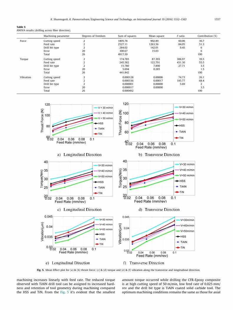
Table 5ANOVA results (drilling across fiber direction).
Machining parameter Degrees of freedom Sum of squares Mean square F ratio Contribution (%)
Force Cutting speed 2 1805.78 902.89 60.06 36.7Feed rate 2 2527.11 1263.56 84.05 51.3Drill bit type 2 284.02 142.01 9.45 6Error 20 300.67 15.03 6Total 26 4917.59 100
Torque Cutting speed 2 174.785 87.393 306.97 39.5Feed rate 2 245.582 122.791 431.30 55.5Drill bit type 2 15.780 7.890 27.71 3.5Error 20 5.694 0.285 1.5Total 26 441.842 100
Vibration Cutting speed 2 0.000128 0.00006 74.73 26.1Feed rate 2 0.000336 0.00017 195.77 68.4Drill bit type 2 0.000001 0.00000 5.69 2Error 20 0.000017 0.00000 3.5Total 26 0.000492 100
Fig. 5. Mean Effect plot for (a) & (b) thrust force; (c) & (d) torque and (e) & (f) vibration along the transverse and longitudinal direction.
K. Shunmugesh, K. Panneerselvam / Engineering Science and Technology, an International Journal 19 (2016) 1552–1563 1557
machining increases linearly with feed rate. The reduced torqueobserved with TiAlN drill tool can be assigned to increased hard-ness and retention of tool geometry during machining comparedthe HSS and TiN. From the Fig. 5 it’s evident that the smallest
amount torque occurred while drilling the CFR-Epoxy compositeis at high cutting speed of 50 m/min, low feed rate of 0.025 mm/rev and the drill bit type is TiAlN coated solid carbide tool. Theoptimummachining conditions remains the same as those for axial

1558 K. Shunmugesh, K. Panneerselvam / Engineering Science and Technology, an International Journal 19 (2016) 1552–1563
thrust, namely highest cutting speed, lowest feed rate and hardesttool material employed for the investigation.
3.3. Effect of cutting speed, feed rate and drill bit type on vibration
The influence vibration on varying the cutting speed, feed rateand drill bit type while drilling CFR-Epoxy composite materialalong the longitudinal and transverse direction are shown in theFig. 5(e and f). When the cutting speed increases from 30 m/minto 50 m/min, the vibration value reduces according, this is due tothe fact that the hardness value of Carbon fiber and drill bit typeare higher. However in the case of the feed rate, the vibration valueincreases when the feed rate increases from 0.025 mm/rev to0.1 mm/rev. In the case of the drill bit type, vibration decreaseswith the drill bit type of TiAlN – coated solid carbide tool butincrease while drilling with the HSS and TiN tool. The vibrationcan be minimized by machining with the combination of high cut-ting speed (50 m/min), low feed rate (0.025 mm/rev) and drill bittype of TiAlN.
3.4. Surface morphology of the drilled holes
SEM images of sample machined surfaces are given in Fig. 6. InFig. 6(a) debonding of fiber from resin is seen. Fig. 6(b) shows asample surface with internal delamination. Fig. 6(c) shows a goodsurface texture while drilling with TiAlN tool at 0.025 mm/rev feedrate. Machining the material with HSS drill bit at cutting speed of30 m/min and feed rate of 0.1 mm/rev shows defects like voids,fiber fracture as illustrated in Fig. 6(d). Fig. 6(e) shows a rough sur-face texture that occurred at machining of 30 m/min and feed rateof 0.1 mm/rev. Fig. 6(f) shows an apparently acceptable surfacetexture that occurred with TiAlN drill tool at 50 m/min cuttingspeed and lowest feed rate employed, 0.025 mm/rev. The surfacequality investigation using SEM suggest optimum surface finish
Fig. 6. SEM Images of drilled
with highest cutting speed employed, lowest feed rate used andhardest tool material TiAlN.
3.5. Optimization of process parameters
3.5.1. Genetic Algorithm (GA)The Genetic Algorithm (GA) [28] is basically population based
search and optimization algorithm used to minimize the objectivefunction subjected to the constraints. The basic idea of GA was firstintroduced by Holland in the year 1975. The GA works on the prin-ciples of natural genetics and search. The computational processesof GA are done by reproduction, crossover and mutation.
In a random fashion, initial the population is set, and then thefitness value of the objective function is calculated based on theinitial population. Once the fitness value is found out and thenby means of roulette wheel selection process, crossover and muta-tion takes place. These process crossover and mutation of the newoffspring continues for the fitness function evaluation.
3.5.2. Numerical simulation of GAGA simulation for the function thrust force along the longitudi-
nal direction
Minimize ¼ 119:061� 0:363056v þ 293:651f � 26:6361d
� 0:00638889v2 � 903:704f 2 þ 6:46111d2
þ 1:94762vf � 0:08vdbþ 15fd
Variable bound Cutting speed (v): 30 6 v 6 50Feed rate (f): 0.025 6 f 6 0.1Drill bit type (d): 1 6 d 6 3
Step 1: The solutions of the Genetic Algorithm are started byinitializing the population of the string which is randomlygenerated.
CFR-Epoxy composite.

K. Shunmugesh, K. Panneerselvam / Engineering Science and Technology, an International Journal 19 (2016) 1552–1563 1559
Step 2: The strings generated randomly are used to evaluate thefitness function. Table 6 shows the fitness value of initialpopulation.
Step 3: Carry out the reproduction process.Step 4: The new population are produced by reproduction,
crossover and mutation. Table 7 shows the mutation andcrossover.
Step 5: The new population is once again used to find the fitnessvalue (Table 8).
Step 6: Check the Termination criteria, since the value of thrustforce did not converge, we move to the next iteration. Repeat thestep 2 until convergence of thrust force is achieved. At the end ofone generation the value of the fitness function reduces from78.34 to 71.362
3.5.3. Particle Swarm Optimization–Gravitational Search Algorithm(PSO–GSA)
Kennedy and Eberhart introduce the concept of the positionand velocity based meta-heuristic algorithm called the PSO in theyear 1995 [29]. The PSO was popular for its efficiency to convergeto the optimum value quickly and it works on the principle ofaltering its position velocity based on the new and its previousvalue.
Rashedi et al. [30] introduced a new population based searchalgorithm called GSA in the year 2007, based on the principal ofgravitational and law of motion. In GSA, the variables are consid-ered as objects and these objects are evaluated by means ofmasses. The variables attract each other by means of the gravita-tional force, which in case move all the variables towards the heav-ier masses. The optimum/good solution for the problemcorresponds to the heavier masses.
Table 6Population and fitness value of GA.
Stringno
Initial population (randomly generated) Decoded value
Cuttingspeed
Feed rate Drill bittype
Cuttingspeed
Feedrate
Drilltype
1 00,011,110 00,011,001 00,000,001 30 0.025 12 00,101,000 00,110,010 00,000,010 40 0.05 23 00,101,101 01,001,011 00,000,010 45 0.075 24 00,110,010 01,100,100 00,000,011 50 0.1 3
Average, favg
Table 7New population of GA after mutation and reproduction.
Mating pool Mate(randomly selected)
Cutting speed Feed rate Drill bit type
00,101,000 00,110,010 00,000,010 400,101,000 00,110,010 00,000,010 300,101,101 01,001,011 00,000,010 200,110,010 01,100,100 00,000,011 1
Table 8New fitness value of GA after mutation and reproduction.
New population decoded valu
Cutting speed Feed rate Drill bit type Cutting speed
00,101,010 00,100,100 00,000,011 4200,101,101 00,101,011 00,000,010 4500,101,001 01,010,110 00,000,010 4100,111,000 01,110,010 00,000,011 56
vdi ðt þ 1ÞPSO ¼ wðtÞvd
i ðtÞ þ c1 � r1 � ðpbestdi � xdi ðtÞÞþ c2 � r2 � ðgbestdi � xdi ðtÞÞ ð1Þ
vdi ðt þ 1Þgsa ¼ randi � vd
i ðtÞ þ adi ðtÞ ð2Þ
vdi ðt þ 1ÞhPSO�gsa ¼ c3 � r3 � vd
i ðt þ 1Þpso þ c4 � ð1� r3Þ � vdi ðt þ 1Þgsa
ð3Þ
xdi ðt þ 1Þ¼xdi ðtÞ þ vdi ðt þ 1ÞhPSO�gsa ð4Þ
where v is the velocity, x is the position, t is the iteration c1, c2, c3and c4 are the acceleration coefficient, r1 and r2 are the randomnumbers. Eqs. (1)–(4) are used to get the velocity and position ofthe new particles. The selection of initial parameter setting inPSO–GSA is very important in obtaining a very good solution.
3.5.4. Numerical simulation of PSO–GSAPSOGSA simulation for the function thrust force along the lon-
gitudinal direction
Minimize ¼ 119:061� 0:363056v þ 293:651f � 26:6361d
� 0:00638889v2 � 903:704f 2 þ 6:46111d2
þ 1:94762vf � 0:08vdbþ 15fd
Variable bound Cutting speed (v): 30 6 v 6 50Feed rate (f): 0.025 6 f 6 0.1Drill bit type (d): 1 6 d 6 3
Step 1: Assume the number of particle/size of the as 4. Initializethe population of cutting speed (v), feed rate (f) and drill bit type
Y = f(X)
fi/favg
Actualcount
Mating pool
bit Cuttingspeed
Feed rate Drill bittype
88.13 1.06 0 00,101,000 00,110,010 00,000,01078.34 0.94 2 00,101,000 00,110,010 00,000,01080.80 0.97 1 00,101,101 01,001,011 00,000,01085.15 1.02 1 00,110,010 01,100,100 00,000,01183.10
Crossover site(randomly selected)
New population
Cutting speed Feed rate Drill bit type
4 00,100,010 00,110,100 00,000,0113 00,101,101 00,101,011 00,000,0103 00,101,000 01,010,010 00,000,0104 00,111,000 01,110,010 00,000,010
e Y = f(X) fi/favg
Feed rate Drill bit type
0.036 3 75.288 0.9540.043 2 71.362 0.9040.086 2 87.447 1.1080.114 3 81.557 1.033Average, favg 78.914

1560 K. Shunmugesh, K. Panneerselvam / Engineering Science and Technology, an International Journal 19 (2016) 1552–1563
(d). The position of the particle is represented as ‘‘X” and its veloc-ity during iteration is represented as ‘‘V”.
Step 2: Based on the position of the particle, evaluate the fitnessfunction and velocities.
Step 3: Update the pBest, select the random numbersStep 4: Update the position and velocity. The best value of the
position, Pbest along with the random numbers uniformly dis-tributed between 0 and 1 is given in Table 9.
Step 5: The initial value of the acceleration, mass and forcerelated to PSO–GSA are set as 0.
Step 6: Update the fitness function value (Pbest) for the newposition and velocity.
Step 7: The updated value of the Pbest and Gbest is shown inTable 10.
Step 8: Check the Termination criteria, since the value of thrustforce did not converge, we move to the iteration 2. Repeat the step2 until convergence of thrust force is achieved.
Iteration 2The results Pbest and Gbest at the end of the iteration 2 are
shown in Table 11.
Table 9PSO–GSA: – Pbest and Updated position and velocity.
Pbest Randomnumber
Current position Velocity
Pbest1 000 0.4516 46.29 0.07 3 �0.0372 0.2014 0.1467Pbest2 000 0.1464 48.11 0.03 3 0.4469 �0.3622 0.3104Pbest3 000 0.4429 32.53 0.04 1 0.4227 0.2152 0.2181Pbest4 000 0.0352 48.26 0.06 3 0.4252 0.4891 �0.0910
Table 10PSO–GSA: Pbest and Gbest.
Pbest Gbest for process parameters Gbest for thrust force
81.3843 Cutting speed Feed rate Drill bit type 26.7267.362188.7138 47.93 0.07 1.7577.8471
Table 11PSO–GSA: – Pbest and Updated position and velocity at the end iteration 2.
Pbest Gbest for process parameters Gbest for thrust force
71.06 Cutting speed Feed rate Drill bit type 71.0677.9575.47 38.46 0.025 275.29
Table 12Parameter setting for GA.
Parameters Values
Fitness function Feasible populationProbability of crossover 0.8Probability of mutation 0.2Initial population size 100No of iterations 51
Table 13Optimum results of GA.
v (m/min) f (mm/rev) d Thrust force
Longitudinal Transverse
50 0.025 TiAlN 59.79 55.23
Since the value of thrust force did not converge, we move to thenext iteration and repeat the step 2 until convergence of thrustforce is achieved.
3.5.5. Validation of GAThe conventional GA available in MATLAB R2012b optimization
toolbox was used to find the optimum values of cutting speed, feedrate and the type of drill bit. The objective functions for the GA areset to be of minimum value. In the current drilling experiments, GAcarries out 27 numbers of trials for each of the objective to mini-mize the thrust force, torque and vibration. The parameter settingfor executing the GA was presented in Table 12.
The objective of minimizing the thrust force, torque and vibra-tion are subjected to the constraints of the machining processparameters such as 30 6 v 6 50, 0.025 6 f 6 0.1 and 1 6 d 6 3.The simulation results of GA along with the optimum machiningconditions are presented in Table 13. The convergence of GAtowards the optimal values is shown in Fig. 7.
From the Fig. 7, it is clear that it takes almost 60 numbers ofgenerations to achieve at the optimum point. But as we see fromthe graph that the convergence of the optimum value is notsmooth enough without oscillations. From the above results ofGA, it possible to predict the machining condition which yieldslow thrust force, torque and vibration while drilling CFR-Epoxycomposite laminate. Finally the optimum machining conditionfor obtaining minimum thrust force, torque and vibration whendrilling CFR-Epoxy composite are at a cutting speed of 50 m/min,feed rate of 0.025 mm/rev and drill bit type of TiAlN solid carbidetool
3.5.6. Validation of PSO–GSAThe PSO–GSA was used to find the optimum values of cutting
speed, feed rate and the type of drill bit. The objective functionsused for the PSO–GSA are set to be of minimum value. In the cur-rent drilling experiments, PSO–GSA carries out 27 numbers of trialsfor each of the objective to minimize the thrust force, torque andvibration. The parameter setting for executing the PSO–GSA waspresented in Table 14.
Optimization of the machining process parameter in drillingCFR-Epoxy composite laminate was done by executing the PSO–GSA using MATLAB R2012b software. The algorithm was executedfor a swarm size of 30 and 100 iterations, to obtain the minimumvalue of thrust force, torque and vibration subjected to the con-straints of the cutting speed, feed rate and drill bit type. The aver-age computational time for executing a single run is of 10 s. Theoptimum levels of process parameters along with the minimumvalues of the objective function obtained from the PSO–GSA arepresented in Table 15.
The convergence of PSO–GSA towards the optimal values isshown in Fig. 8.
From the Fig. 8, it is clear that it takes only few numbers of iter-ations to achieve at the optimum point. Also it is observed that theconvergence of the optimum value is smooth enough withoutmuch oscillation when compared to the GA. Hence it is concludedthat the PSO–GSA is more powerful than the GA in arriving at theoptimal solution quickly without much delay.
Torque Vibration
Longitudinal Transverse Longitudinal Transverse
22.1988 22.1543 0.0310 0.0310

a) Longitudinal Direction b) Transverse Direction
c) Longitudinal Direction d) Transverse Direction
e) Longitudinal Direction f) Transverse Direction
Fig. 7. (a–f) Fitness values of thrust force, torque and vibration vs no of generation in GA.
Table 14Parameter setting for PSO–GSA.
Parameters Values
Size of the swarm, N 30Max iteration 100PSO parameter, C1 0.5PSO parameter, C2 1.5Gravitational constant, G0 1
K. Shunmugesh, K. Panneerselvam / Engineering Science and Technology, an International Journal 19 (2016) 1552–1563 1561
3.6. Comparison of the GA and PSO–GSA the optimum condition
The predicted values at the optimum machining conditions(50 m/min, 0.025 mm/rev and TiAlN-Drill Bit type) obtained fromthe GA and PSO–GSA are tabulated and presented in Table 16.These values clearly indicate that their exist correlation betweenthe actual and predicted value. Also it is evident that the resultsof PSO–GSA are more superior to the GA. Hence we conclude thatthe hybrid PSO–GSA is more powerful tool and can be extend to allthe other application of engineering problems.

Table 15Optimum results of PSO–GSA.
v (m/min) f (mm/rev) d Thrust force Torque Vibration
Transverse Longitudinal Transverse Longitudinal Transverse Longitudinal
50 0.025 TiAlN 59.78 55.213 22.1988 22.1505 0.0310 0.0310
Fig. 8. Fitness values of thrust force, torque and vibration vs no of iteration of PSO–GSA.
1562 K. Shunmugesh, K. Panneerselvam / Engineering Science and Technology, an International Journal 19 (2016) 1552–1563

Table 16Comparison of results obtained from the confirmation test.
Algorithm Thrust force Torque Vibration
Transverse Longitudinal Transverse Longitudinal Transverse Longitudinal
GA 59.7962 55.2374 22.1988 22.1543 0.031 0.0301PSO–GSA 59.7894 55.2134 22.1988 22.1505 0.0310 0.0301
K. Shunmugesh, K. Panneerselvam / Engineering Science and Technology, an International Journal 19 (2016) 1552–1563 1563
4. Conclusions
Machining trials by drilling holes on CFR-Epoxy composite wasperformed at different levels of cutting speed, feed rate and usingdrills made different tool material types, to evaluate axial thrust,drilling torque and work vibrations. The experimental data andthe analysis performed point to the following conclusions:
1. Axial thrust decreases with increasing cutting speed, increaseswith increasing feed rate and is minimum with hardest toolmaterial employed. The value of thrust force in drilling in adirection normal to the fiber is more than those for along thefiber.
2. The optimum machining conditions for the input parametersinvestigated are the highest cutting speed, the lowest feed rateand the hardest tool material employed.
3. The ANOVA analysis of the data indicate that the feed rate is themost influential process parameter which affects the thrustforce, torque and work vibration.
4. The SEM analysis of the machined surface indicate occurrenceof debonding defects at the surface, internal delamination dur-ing machining exposed to the surface generated, presence ofdefects like voids, fiber fracture and rough surface texture atcertain machining conditions. The optimum surface finishappears to occur at the highest cutting speed, lowest feed rateand hardest tool material employed. The selection of optimummachining conditions appears critical in avoiding the defects.
5. The GA and PSO–GSA techniques were employed to predictoptimum machining conditions over the ranges of parametersinvestigated. The predicted result of the two techniques agreesclosely. The PSO–GSA appears superior to the RSM and GA tech-niques in terms of computational time and the number of iter-ations to arrive at the end results.
References
[1] C.C. Tsao, Evaluation of the drilling-induced delamination of compound core-special drills using response surface methodology based on the Taguchimethod, Int. J. Adv. Manuf. Technol. 62 (1–4) (2012) 241–247.
[2] Maxime Montoya, Madalina Calamaz, Daniel Gehin, Franck Girot, Evaluation ofthe performance of coated and uncoated carbide tools in drilling thick CFRP/aluminium alloy stacks, Int. J. Adv. Manuf. Technol. 68 (9–12) (2013) 2111–2120.
[3] Yosra Turki, Malek Habak, Raphaël Velasco, Zoheir Aboura, Kamel Khellil,Pascal Vantomme, Experimental investigation of drilling damage and stitchingeffects on the mechanical behavior of carbon/epoxy composites, Int. J. Mach.Tools Manuf 87 (2014) 61–72.
[4] Ozden Isbilir, Elaheh Ghassemieh, Finite element analysis of drilling of carbonfibre reinforced composites, Appl. Compos. Mater. 19 (3–4) (2012) 637–656.
[5] Isbilir Ozden, Elaheh Ghassemieh, Delamination and wear in drilling of carbon-fiber reinforced plastic composites using multilayer TiAlN/TiN PVD-coatedtungsten carbide tools, J. Reinf. Plast. Compos. 31 (10) (2012) 717–727.
[6] Shahrajabian Hamzeh, Masoud Farahnakian, Modeling and multi-constrainedoptimization in drilling process of carbon fiber reinforced epoxy composite,Int. J. Precis. Eng. Manuf. 14 (10) (2013) 1829–1837.
[7] Abhishek Kumar, V. Rakesh Kumar, Saurav Datta, Siba Sankar Mahapatra,Parametric appraisal and optimization in machining of CFRP composites byusing TLBO (teaching-learning based optimization algorithm), J. Intell. Manuf.(2015) 1–17.
[8] Cédric Bonnet, Gérard Poulachon, Joël Rech, Yannick Girard, Jean PhilippeCostes, CFRP drilling: fundamental study of local feed force and consequenceson hole exit damage, Int. J. Mach. Tools Manuf 94 (2015) 57–64.
[9] P. Sam Paul, A.S. Varadarajan, R. Robinson Gnanadurai, Study on the influenceof fluid application parameters on tool vibration and cutting performanceduring turning of hardened steel, Eng. Sci. Technol. Int. J. 19 (1) (2016)241–253.
[10] Jinyang Xu, Qinglong An, Ming Chen, A comparative evaluation ofpolycrystalline diamond drills in drilling high-strength T800S/250F CFRP,Compos. Struct. 117 (2014) 71–82.
[11] N. Feito, J. López-Puente, C. Santiuste, M.H. Miguélez, Numerical prediction ofdelamination in CFRP drilling, Compos. Struct. 108 (2014) 677–683.
[12] Eshetu D. Eneyew, Mamidala Ramulu, Experimental study of surface qualityand damage when drilling unidirectional CFRP composites, J. Mater. Res.Technol. 3 (4) (2014) 354–362.
[13] Juan C. Campos Rubio, Alexandre M. Abrão, Paulo Eustáquio Faria, AntônioEsteves Correia, João Paulo Davim, Delamination in high speed drilling ofcarbon fiber reinforced plastic (CFRP), J. Compos. Mater. 42 (15) (2008)1523–1532.
[14] A. Krishnamoorthy, S. Rajendra Boopathy, K. Palanikumar, J. Paulo Davim,Application of grey fuzzy logic for the optimization of drilling parameters forCFRP composites with multiple performance characteristics, Measurement 45(5) (2012) 1286–1296.
[15] Vijayan Krishnaraj, A. Prabukarthi, Arun Ramanathan, N. Elanghovan, M.Senthil Kumar, Redouane Zitoune, J.P. Davim, Optimization of machiningparameters at high speed drilling of carbon fiber reinforced plastic (CFRP)laminates, Compos. B Eng. 43 (4) (2012) 1791–1799.
[16] K. Palanikumar, Experimental investigation and optimisation in drilling ofGFRP composites, Measurement 44 (10) (2011) 2138–2148.
[17] S.R. Karnik, V.N. Gaitonde, J. Campos Rubio, A. Esteves Correia, A.M. Abrão, J.Paulo Davim, Delamination analysis in high speed drilling of carbon fiberreinforced plastics (CFRP) using artificial neural network model, Mater. Design29 (9) (2008) 1768–1776.
[18] T.J. Grilo, R.M.F. Paulo, C.R.M. Silva, J.P. Davim, Experimental delaminationanalyses of CFRPs using different drill geometries, Compos. B Eng. 45 (1)(2013) 1344–1350.
[19] A. Sadek, M. Meshreki, M.H. Attia, Characterization and optimization of orbitaldrilling of woven carbon fiber reinforced epoxy laminates, CIRP Ann. Manuf.Technol. 61 (1) (2012) 123–126.
[20] Ramon Quiza Sardinas, Pedro Reis, J. Paulo Davim, Multi-objectiveoptimization of cutting parameters for drilling laminate composite materialsby using genetic algorithms, Compos. Sci. Technol. 66 (15) (2006) 3083–3088.
[21] Mihai-Bogdan Lazar, Paul Xirouchakis, Experimental analysis of drilling fiberreinforced composites, Int. J. Mach. Tools Manuf 51 (12) (2011) 937–946.
[22] Ozden Isbilir, Elaheh Ghassemieh, Numerical investigation of the effects ofdrill geometry on drilling induced delamination of carbon fiber reinforcedcomposites, Compos. Struct. 105 (2013) 126–133.
[23] M. Balasubbareddy, S. Sivanagaraju, V. Chintalapudi Suresh, Multi-objectiveoptimization in the presence of practical constraints using non-dominatedsorting hybrid cuckoo search algorithm, Eng. Sci. Technol. Int. J. 18 (2015)603–615.
[24] Meenu Gupta, Surinder Kumar, Investigation of surface roughness and MRR forturning of UD-GFRP using PCA and Taguchi method, Eng. Sci. Technol. Int. J. 18(1) (2015) 70–81.
[25] Shanhe Jiang, Zhicheng Ji, Yanxia Shen, A novel hybrid particle swarmoptimization and gravitational search algorithm for solving economicemission load dispatch problems with various practical constraints, Int. J.Electr. Power Energy Syst. 55 (2014) 628–644.
[26] Singiresu S. Rao, S.S. Rao, Engineering optimization: theory and practice, JohnWiley & Sons, 2009.
[27] Seyedali Mirjalili, Mohd Hashim Siti Zaiton, A new hybrid PSOGSA algorithmfor function optimization, in: Computer and information application (ICCIA),2010 International Conference, IEEE, 2010, pp. 374–377.
[28] Kalyanmoy Deb, An introduction to genetic algorithms, Sadhana 24 (4-5)(1999) 293–315.
[29] J. Kennedy, R.C. Eberhart, Particle swarm optimization, Proceedings of theIEEE International Conference on Neural Networks, Piscataway, 1995,pp. 1942–1948.
[30] Esmat Rashedi, Hossein Nezamabadi-Pour, Saeid Saryazdi, GSA: a gravitationalsearch algorithm, Inf. Sci. 179 (13) (2009) 2232–2248.


![バロン氏ドナー角膜パンチ[Barron Donor Cornea Punch] バロン氏ドナー角膜パンチ K20-2084 9.5 mm K20-2083 9.25mm K20-2082 9.0 mm K20-2081 8.75mm K20-2080 8.5 mm](https://static.fdocuments.net/doc/165x107/60e20f5bd5f8a83bdf2e686d/ffffffeeoefff-barron-donor-cornea-punch-ffffffeeoefff.jpg)