Packet delay analysis of the advanced infrared (AIr) CSMA/CA MAC
13 August 2012 EPoC Performance Model – v05 1
EPoC Performance Model Delay and Efficiency
Andrea Garavaglia – Qualcomm Ed Boyd – Broadcom
Rick Li – Cortina Bill Powell – Alcatel-Lucent
Hesham ElBakoury – Huawei

13 August 2012 EPoC Performance Model – v05 2
Disclaimer The EPoC performance model aim at providing a tool (spreadsheet) to
play with tradeoff between delay and efficiency of EPoC systems
Input values are parameterized so that different solutions/option could be considered when evaluating delay and efficiency of certain proposal
The focus of the EPoC performance model is primarily on the coax PHY and also includes additional impact due to MPCP/MAC layer
…

13 August 2012 EPoC Performance Model – v05 3
Focus on delay but also consider efficiency For both delay and efficiency, two components: PHY and MAC Look at worst case in supported multi-user scenarios Is 1 Gb/s PAR objective to individual CNU or on coax segment? → Q5
Efficiency: need to know how much efficiency is consumed by overhead due e.g. guard interval, guard bands, etc. – focus on relative figures and efficiency on the coax side – how the trade-off affects delay vs. efficiency
Improve the model with further details Consider symbol duration
Consider preamble presence/duration
Split propagation time (cable length) from switching time
– Transmit/receive sharing PHY and influence on the switching time
Number of simultaneous transmitters
Important question is: does the absolute numbers meet the delay/jitter requirements?
MAC Performance Model - Summary
13 August 2012 EPoC Performance Model – v05 4
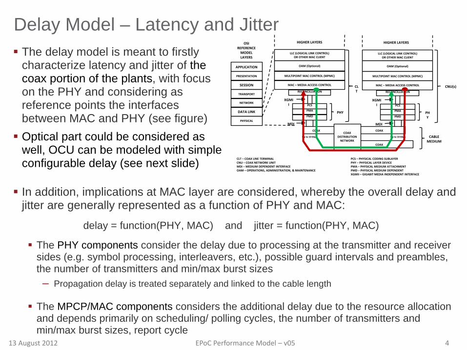
Delay Model – Latency and Jitter The delay model is meant to firstly
characterize latency and jitter of the coax portion of the plants, with focus on the PHY and considering as reference points the interfaces between MAC and PHY (see figure) Optical part could be considered as
well, OCU can be modeled with simple configurable delay (see next slide)
APPLICATION
PRESENTATION
SESSION
TRANSPORT
NETWORK
DATA LINK
PHYSICAL
OAM (Optional)
MULTIPOINT MAC CONTROL (MPMC)
MAC – MEDIA ACCESS CONTROL
RECONCILLIATION
PCS
PMA
PMD
OSI REFERENCE
MODEL LAYERS
HIGHER LAYERS
PHY
XGMII
MDI
Up to 10 Gbps
CLT – COAX LINE TERMINAL CNU – COAX NETWORK UNIT MDI – MEDIUM DEPENDENT INTERFACE OAM – OPERATIONS, ADMINISTRATION, & MAINTENANCE
PCS – PHYSICAL CODING SUBLAYER PHY – PHYSICAL LAYER DEVICE PMA – PHYSICAL MEDIUM ATTACHMENT PMD – PHYSICAL MEDIUM DEPENDENT XGMII – GIGABIT MEDIA INDEPENDENT INTERFACE
LLC (LOGICAL LINK CONTROL) OR OTHER MAC CLIENT
OAM (Optional)
MULTIPOINT MAC CONTROL (MPMC)
MAC – MEDIA ACCESS CONTROL
RECONCILLIATION
PCS
PMA
PMD
HIGHER LAYERS
PHY
XGMII
MDI
LLC (LOGICAL LINK CONTROL) OR OTHER MAC CLIENT
CLT
CNU(s)
Up to 10 Gbps
COAX COAX
COAX
COAX DISTRIBUTION
NETWORK CABLE
MEDIUM
In addition, implications at MAC layer are considered, whereby the overall delay and jitter are generally represented as a function of PHY and MAC:
delay = function(PHY, MAC) and jitter = function(PHY, MAC)
The PHY components consider the delay due to processing at the transmitter and receiver sides (e.g. symbol processing, interleavers, etc.), possible guard intervals and preambles, the number of transmitters and min/max burst sizes – Propagation delay is treated separately and linked to the cable length
The MPCP/MAC components considers the additional delay due to the resource allocation and depends primarily on scheduling/ polling cycles, the number of transmitters and min/max burst sizes, report cycle

13 August 2012 EPoC Performance Model – v05 5
Delay Model – Reference Scenarios
CNU
EPoC delay
CNU
CNU
CNU
CLT FN
CNU
CNU
CNU
OLT OCU
(a)
(b)
(c)
Analog fiber propagation delay
EPON delay
OCU delay
CNUEPoC delay
CNUCLT
EPoC delay
The EPoC performance model is focus on the EPoC part, for which a detailed model will be developed to characterize delay and efficiency tradeoffs. The case of EPoC deployed with analog fiber and CLT in headend can be easily considered adding analog fiber delay as function of the optical fiber length. Similarly, the case of EPON with digital fiber can be easily considered adding EPON delay and OCU delay terms. Note: no detailed model for EPON or HFC will be developed
Shall be kept or removed?

13 August 2012 EPoC Performance Model – v05 6
Delay Model – PHY for FDD downstream
CLT down delay
CLT up delay
Scheduler delay
Coax down delay
Coax up delay
Mod
ulat
ion
FEC
enco
ding
Sym
bol I
FFT
Inte
rleav
er
MAC
Tra
nsm
it
Dem
odul
atio
n
FEC
deco
ding
Sym
bol F
FT
Dein
terle
aver
MAC
Rec
eive
Mod
ulat
ion
FEC
enco
ding
Sym
bol I
FFT
Inte
rleav
er
MAC
Tra
nsm
it
Dem
odul
atio
n
FEC
deco
ding
Sym
bol F
FT
Dein
terle
aver
MAC
rece
ive
CNU down delay
CNU up delay
In case of FDD downstream there is a continuous transmission consisting in a sequence of DS symbols Generally speaking the PHY needs to perform operations for: FEC encoding/decoding Interleaving/de-interleaving Modulation/demodulation Symbol IFFT/FFT Some of the operations are block-level processing related to symbol duration – some may not be present See next slide for details
Time @ TX
Ts_ds Ts_ds Ts_ds Ts_ds ...Ts_ds Ts_ds Ts_ds Ts_ds...
Time @ RX
Ts_ds Ts_ds Ts_ds Ts_ds ...Ts_ds Ts_ds Ts_ds Ts_ds...
DS Symbol
Cyclic Prefix
DS Symbol
Cyclic Prefix
Delay
13 August 2012 EPoC Performance Model – v05 7
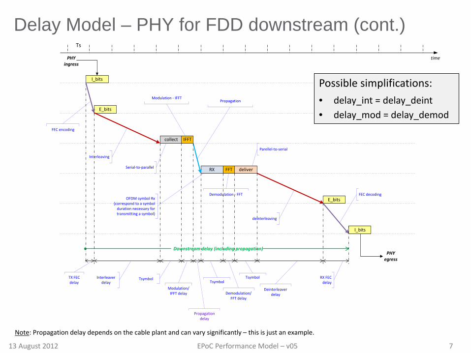
Delay Model – PHY for FDD downstream (cont.)
E_bits
collect IFFT
Ts
RX deliver
time
Downstream delay (including propagation)
PHY ingress
PHY egress
I_bits
FFT
E_bits
I_bits
Serial-to-parallel
Parellel-to-serial
Modulation - IFFTPropagation
OFDM symbol Rx (correspond to a symbol
duration necessary for transmitting a symbol)
Interleaving
Demodulation - FFT
FEC encoding
deinterleaving
FEC decoding
TX FEC delay
Interleaver delay
Tsymbol
Modulation/IFFT delay
Tsymbol
Demodulation/FFT delay
Propagation delay
Tsymbol
Deinterleaver delay
RX FEC delay
Possible simplifications: • delay_int = delay_deint • delay_mod = delay_demod
Note: Propagation delay depends on the cable plant and can vary significantly – this is just an example.
13 August 2012 EPoC Performance Model – v05 8
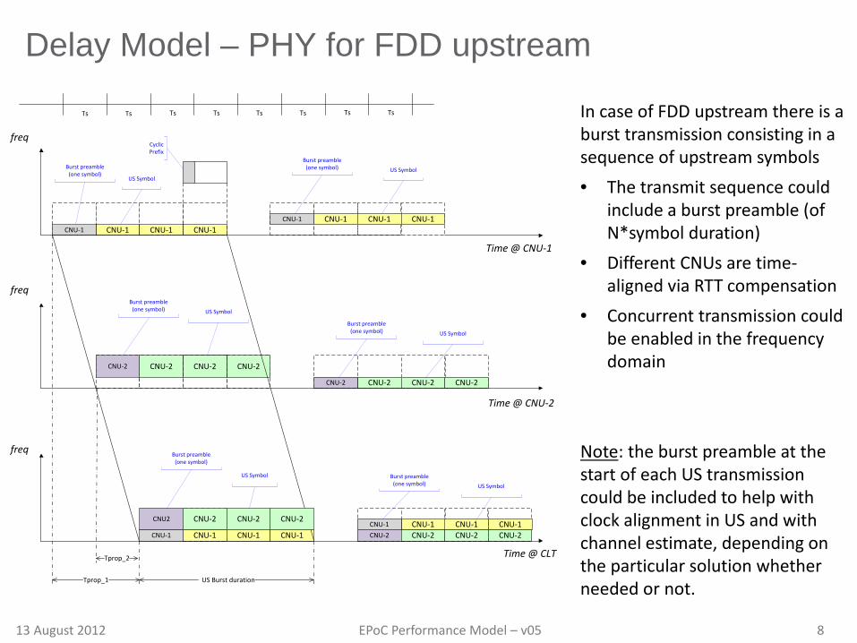
Delay Model – PHY for FDD upstream
In case of FDD upstream there is a burst transmission consisting in a sequence of upstream symbols • The transmit sequence could
include a burst preamble (of N*symbol duration)
• Different CNUs are time-aligned via RTT compensation
• Concurrent transmission could be enabled in the frequency domain
Note: the burst preamble at the start of each US transmission could be included to help with clock alignment in US and with channel estimate, depending on the particular solution whether needed or not.
Time @ CNU-1
CNU-1 CNU-1 CNU-1CNU-1
freq
Time @ CNU-2
CNU-2CNU-2
CNU-2CNU-2
freq
Time @ CLT
CNU2
freq
Tprop_1
Tprop_2
CNU-2
CNU-2
CNU-1 CNU-1 CNU-1
CNU-1 CNU-1CNU-1
CNU-2CNU-2 CNU-2
CNU-1 CNU-1CNU-2 CNU-2 CNU-2
CNU-1
CNU-2
CNU-1CNU-2
US Burst duration
Ts Ts Ts Ts Ts Ts Ts Ts
CNU-2CNU-2CNU-1
CNU-1
US Symbol
Cyclic Prefix
Burst preamble (one symbol)
US Symbol
Burst preamble (one symbol)
Burst preamble (one symbol)
US Symbol
Burst preamble (one symbol)
Burst preamble (one symbol) US Symbol
Burst preamble (one symbol) US Symbol
US Symbol
13 August 2012 EPoC Performance Model – v05 9
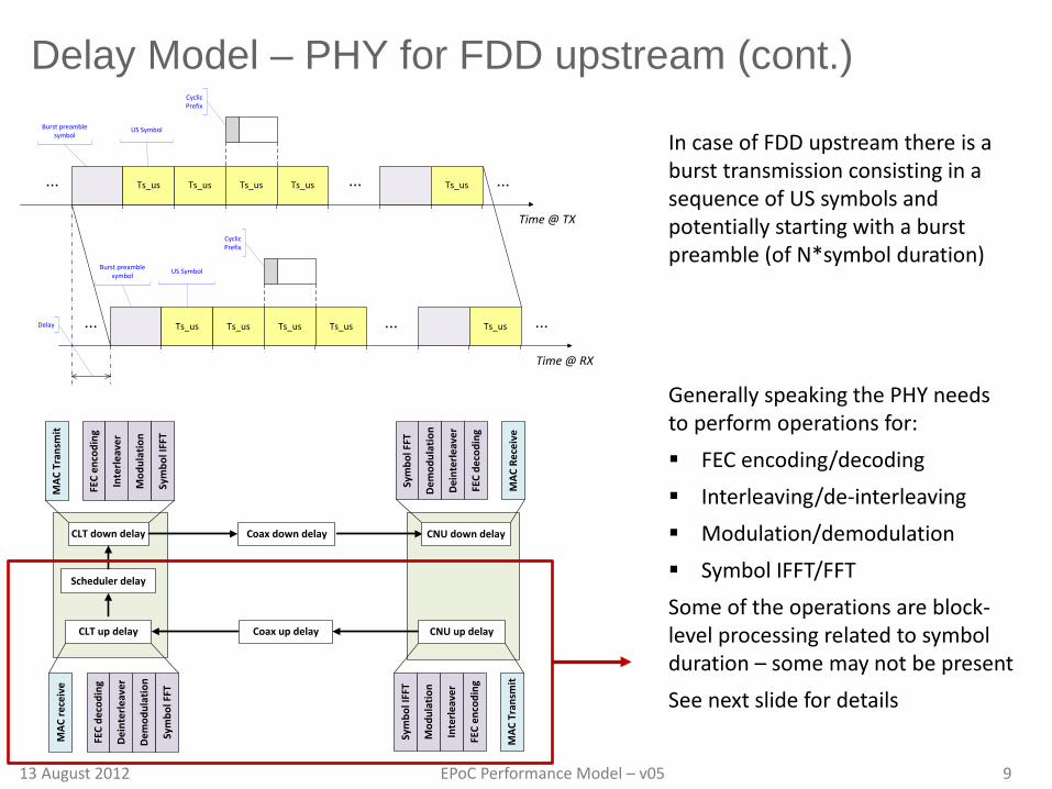
Delay Model – PHY for FDD upstream (cont.)
CLT down delay
CLT up delay
Scheduler delay
Coax down delay
Coax up delay
Mod
ulat
ion
FEC
enco
ding
Sym
bol I
FFT
Inte
rleav
er
MAC
Tra
nsm
it
Dem
odul
atio
n
FEC
deco
ding
Sym
bol F
FT
Dein
terle
aver
MAC
Rec
eive
Mod
ulat
ion
FEC
enco
ding
Sym
bol I
FFT
Inte
rleav
er
MAC
Tra
nsm
it
Dem
odul
atio
n
FEC
deco
ding
Sym
bol F
FT
Dein
terle
aver
MAC
rece
ive
CNU down delay
CNU up delay
In case of FDD upstream there is a burst transmission consisting in a sequence of US symbols and potentially starting with a burst preamble (of N*symbol duration) Generally speaking the PHY needs to perform operations for: FEC encoding/decoding Interleaving/de-interleaving Modulation/demodulation Symbol IFFT/FFT Some of the operations are block-level processing related to symbol duration – some may not be present See next slide for details
Time @ TX
Ts_us Ts_us Ts_us ...Ts_us Ts_us...
Time @ RX
Ts_us Ts_us Ts_us ...Ts_us Ts_us...
...
...
US Symbol
Cyclic Prefix
US Symbol
Cyclic Prefix
Delay
Burst preamble symbol
Burst preamble symbol

13 August 2012 EPoC Performance Model – v05 10
Delay Model – PHY for FDD upstream (cont.)
E_bits
collect IFFT
Ts
RX deliver
time
Upstream delay (including propagation)
PHY ingress
PHY egress
I_bits
FFT
E_bits
I_bits
Serial-to-parallel
Parellel-to-serial
Modulation - IFFTPropagation
OFDM symbol Rx (correspond to a symbol
duration necessary for transmitting a symbol)
Interleaving
Demodulation - FFT
FEC encoding
deinterleaving
FEC decoding
TX FEC delay
Interleaver delay
Tsymbol
Modulation/IFFT delay
Tsymbol
Demodulation/FFT delay
Propagation delay
Tsymbol
Deinterleaver delay
RX FEC delay
Interleaver/deinterleaver duration for US is related to the upstream burst duration, which
can be expressed as integer number of US symbols and may include a preamble symbol
Possible simplifications: • delay_int = delay_deint • delay_mod = delay_demod
Note: Propagation delay depends on the cable plant and can vary significantly – this is just an example.

13 August 2012 EPoC Performance Model – v05 11
Delay Model – PHY for FDD summary In case of FDD, the delay model results in the following terms:
FDD_PHY_delay_DS = Tencode + 2*TFDD_DS_Int + 3*TDS_symb + 2*Tmod_FFT + Tdecode
FDD_PHY_delay_US = Tencode + 2*TFDD_US_Int + 3*TUS_symb + 2*Tmod_FFT + Tdecode
Tpropagation_oneway = Lcable / (0.87*c) where c is the speed of light in vacuum Note: The following assumption and considerations holds
• Delay of interleaver and deinterleaver in one direction are the same • Delay for modulation/IFFT and demodution/FFT are the same • Encoder/decoder are the same for DS and US • Modulation/demodulation are the same for DS and US • Different symbol duration for DS and US are possible • Different interleavers for DS and US are possible
• interleaver length is related to burst noise characteristics and in case of US the transmission burst may be equal or a multiple of the interleaver length
• US interleaver from multiple CNUs may be inefficient against burst noise
13 August 2012 EPoC Performance Model – v05 12
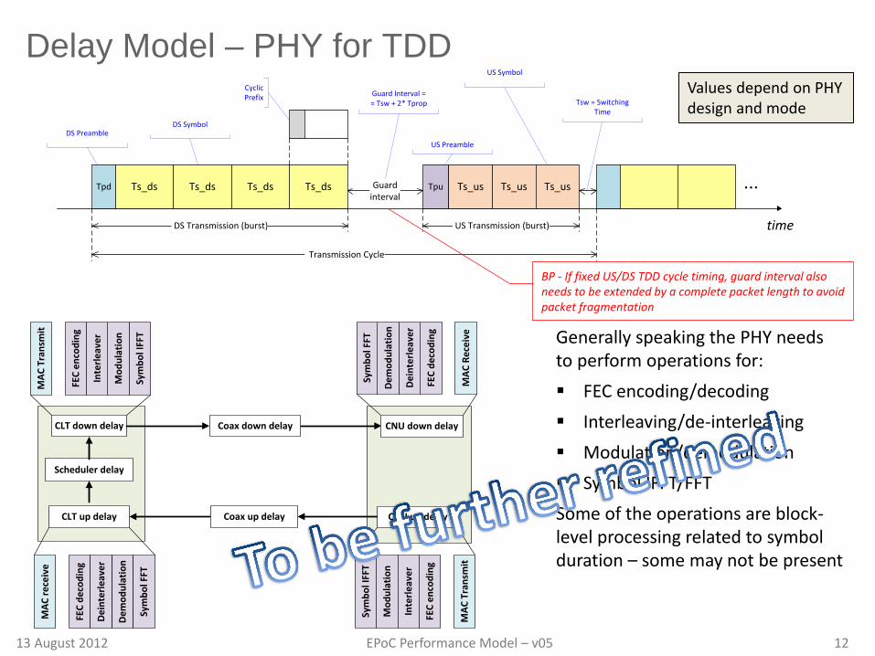
Delay Model – PHY for TDD
time
Tpd Ts_ds Ts_ds Ts_ds Ts_ds Tpu Ts_us Ts_us Ts_us ...Guardinterval
DS Transmission (burst) US Transmission (burst)
Transmission Cycle
DS PreambleUS Preamble
Tsw = Switching Time
Guard Interval = = Tsw + 2* Tprop
DS Symbol
US Symbol
Cyclic Prefix
CLT down delay
CLT up delay
Scheduler delay
Coax down delay
Coax up delay
Mod
ulat
ion
FEC
enco
ding
Sym
bol I
FFT
Inte
rleav
er
MAC
Tra
nsm
it
Dem
odul
atio
n
FEC
deco
ding
Sym
bol F
FT
Dein
terle
aver
MAC
Rec
eive
Mod
ulat
ion
FEC
enco
ding
Sym
bol I
FFT
Inte
rleav
er
MAC
Tra
nsm
it
Dem
odul
atio
n
FEC
deco
ding
Sym
bol F
FT
Dein
terle
aver
MAC
rece
ive
CNU down delay
CNU up delay
Values depend on PHY design and mode
Generally speaking the PHY needs to perform operations for: FEC encoding/decoding Interleaving/de-interleaving Modulation/demodulation Symbol IFFT/FFT Some of the operations are block-level processing related to symbol duration – some may not be present
BP - If fixed US/DS TDD cycle timing, guard interval also needs to be extended by a complete packet length to avoid packet fragmentation
13 August 2012 EPoC Performance Model – v05 13
Delay Model – PHY components (cont.) …
13 August 2012 EPoC Performance Model – v05 14
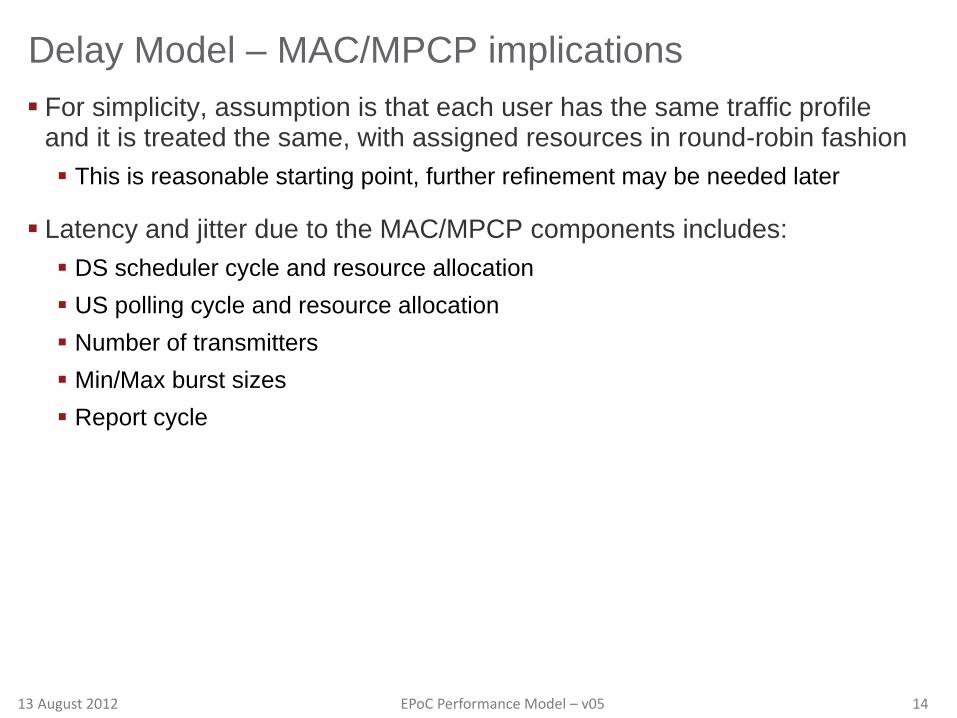
Delay Model – MAC/MPCP implications For simplicity, assumption is that each user has the same traffic profile
and it is treated the same, with assigned resources in round-robin fashion This is reasonable starting point, further refinement may be needed later
Latency and jitter due to the MAC/MPCP components includes: DS scheduler cycle and resource allocation US polling cycle and resource allocation Number of transmitters Min/Max burst sizes Report cycle
13 August 2012 EPoC Performance Model – v05 15
Delay Model – MAC/MPCP components (cont.) …

13 August 2012 EPoC Performance Model – v05 16
Efficiency Model – …

13 August 2012 EPoC Performance Model – v05 17
Backup Material
13 August 2012 EPoC Performance Model – v05 18
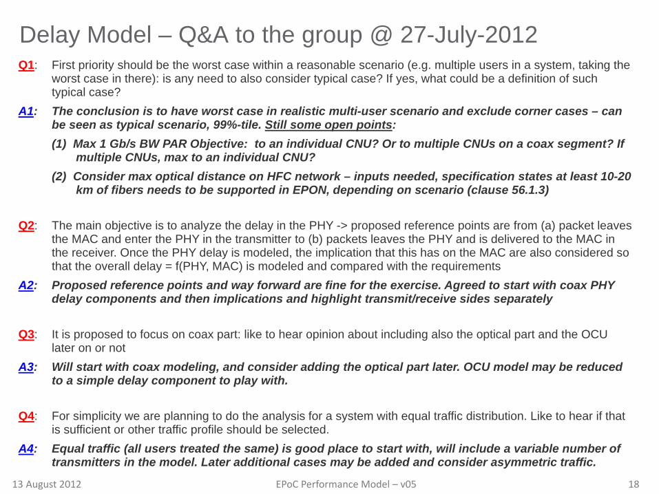
Delay Model – Q&A to the group @ 27-July-2012 Q1: First priority should be the worst case within a reasonable scenario (e.g. multiple users in a system, taking the
worst case in there): is any need to also consider typical case? If yes, what could be a definition of such typical case?
A1: The conclusion is to have worst case in realistic multi-user scenario and exclude corner cases – can be seen as typical scenario, 99%-tile. Still some open points: (1) Max 1 Gb/s BW PAR Objective: to an individual CNU? Or to multiple CNUs on a coax segment? If
multiple CNUs, max to an individual CNU? (2) Consider max optical distance on HFC network – inputs needed, specification states at least 10-20
km of fibers needs to be supported in EPON, depending on scenario (clause 56.1.3)
Q2: The main objective is to analyze the delay in the PHY -> proposed reference points are from (a) packet leaves the MAC and enter the PHY in the transmitter to (b) packets leaves the PHY and is delivered to the MAC in the receiver. Once the PHY delay is modeled, the implication that this has on the MAC are also considered so that the overall delay = f(PHY, MAC) is modeled and compared with the requirements
A2: Proposed reference points and way forward are fine for the exercise. Agreed to start with coax PHY delay components and then implications and highlight transmit/receive sides separately
Q3: It is proposed to focus on coax part: like to hear opinion about including also the optical part and the OCU later on or not
A3: Will start with coax modeling, and consider adding the optical part later. OCU model may be reduced to a simple delay component to play with.
Q4: For simplicity we are planning to do the analysis for a system with equal traffic distribution. Like to hear if that is sufficient or other traffic profile should be selected.
A4: Equal traffic (all users treated the same) is good place to start with, will include a variable number of transmitters in the model. Later additional cases may be added and consider asymmetric traffic.